instruction manual mtl hmi and visualisation inm mtl gecma ... · inm mtl gecma rt com rev 2...
TRANSCRIPT
DRAFT - 04 March 2016
MTL GECMA RT COM moduleModular communications interface forMTL GECMA work stations
September 2016INM MTL GECMA RT COM rev 2
Instruction manualMTL HMI and visualisation
DRAFT - 04 March 2016 DRAFT - 04 March 2016
INM MTL GECMA RT COM rev 22
1 FOREWORD
Please read the entire operating instructions before starting the assembly, connection, installation and commissioning.
The GECMA RT COM module and any associated safe area equipment must be installed or uninstalled by qualified personnel only. This individual must be qualified to perform the installation of electrical equipment for use in potentially explosive atmospheres, and in accordance to the relevant rules and regulations pursuant to the classification of zones under IEC 60079-14.
The information in the IECEx or EC-type examination certificate should be fully adhered to.
If you have any questions or require technical support, please contact:
Eaton’s Crouse-Hinds division
GECMA Components electronic GmbH Heinrich-Hertz-Strasse 12 50170 Kerpen, Germany
Tel: +49 2273 9812 0 Fax: +49 2273 9812 100 [email protected] www.gecma.com
Technical developments
The given data is only intended as a product description and should not be regarded as a legal warranty of properties or guarantee. In the interest of further technical developments, we reserve the right to make design changes.
Trademarks used:
IBM is a registered trademark of International Business Machines Corporation.
Microsoft, Windows and Windows NT are registered trademarks of Microsoft Corporation.
All other trademarks mentioned and shown in the text are trademarks of the respective owners and are recognised as protected.
© 2016 by GECMA Components electronic GmbH
2 DECLARATION OF CONFORMITY A printed version of the Declaration of Conformity has been provided separately within the original shipment of goods. However, you can find a copy of the latest version at http://www.mtl-inst.com/certificates
DRAFT - 04 March 2016 DRAFT - 04 March 2016
INM MTL GECMA RT COM rev 2 3
CONTENTS
1 FOREWORD . . . . . . . . . . . . . . . . . . . . . . . . . . . . . . . . . . . . . . . . . . . . . . . . . . . . . . . . . . . . . . . 2
2 DECLARATION OF CONFORMITY . . . . . . . . . . . . . . . . . . . . . . . . . . . . . . . . . . . . . . . . . . . . . 2
3 GENERAL REFERENCE . . . . . . . . . . . . . . . . . . . . . . . . . . . . . . . . . . . . . . . . . . . . . . . . . . . . . . 43.1 General safety information . . . . . . . . . . . . . . . . . . . . . . . . . . . . . . . . . . . . . . . . . . . . . . . . . . . . . . . . . . . . . . . .4
3.2 Provisions for general operational safety . . . . . . . . . . . . . . . . . . . . . . . . . . . . . . . . . . . . . . . . . . . . . . . . . . . .5
3.3 Application . . . . . . . . . . . . . . . . . . . . . . . . . . . . . . . . . . . . . . . . . . . . . . . . . . . . . . . . . . . . . . . . . . . . . . . . . . . . .5
3.4 Safety guidelines . . . . . . . . . . . . . . . . . . . . . . . . . . . . . . . . . . . . . . . . . . . . . . . . . . . . . . . . . . . . . . . . . . . . . . . .5
3.5 ATEX safety instructions . . . . . . . . . . . . . . . . . . . . . . . . . . . . . . . . . . . . . . . . . . . . . . . . . . . . . . . . . . . . . . . . 5-7
3.6 Safety provisions . . . . . . . . . . . . . . . . . . . . . . . . . . . . . . . . . . . . . . . . . . . . . . . . . . . . . . . . . . . . . . . . . . . . . . 7/8
3.7 Errors and overloading . . . . . . . . . . . . . . . . . . . . . . . . . . . . . . . . . . . . . . . . . . . . . . . . . . . . . . . . . . . . . . . . . . .8
4 OVERVIEW . . . . . . . . . . . . . . . . . . . . . . . . . . . . . . . . . . . . . . . . . . . . . . . . . . . . . . . . . . . . . . . . . . . . . . . . 9
5 MTL GECMA RT COM MODULE . . . . . . . . . . . . . . . . . . . . . . . . . . . . . . . . . . . . . . . . . . . . . . . . . . . . . . . 95.1 Technical data . . . . . . . . . . . . . . . . . . . . . . . . . . . . . . . . . . . . . . . . . . . . . . . . . . . . . . . . . . . . . . . . . . . . . . . . . . .9
6 INSTALLATION . . . . . . . . . . . . . . . . . . . . . . . . . . . . . . . . . . . . . . . . . . . . . . . . . . . . . . . . . . . . . . . . . . . . 106.1 General information . . . . . . . . . . . . . . . . . . . . . . . . . . . . . . . . . . . . . . . . . . . . . . . . . . . . . . . . . . . . . . . . . . . . .10
6.2 Mechanical installation . . . . . . . . . . . . . . . . . . . . . . . . . . . . . . . . . . . . . . . . . . . . . . . . . . . . . . . . . . . . . . . . . .10
6.3 Electrical connections. . . . . . . . . . . . . . . . . . . . . . . . . . . . . . . . . . . . . . . . . . . . . . . . . . . . . . . . . . . . . . . . . . . . 11
6.3.1 DC power connection . . . . . . . . . . . . . . . . . . . . . . . . . . . . . . . . . . . . . . . . . . . . . . . . . . . . . . . . . . . . . . . . . . 11
6.3.2 Peripheral equipment connections . . . . . . . . . . . . . . . . . . . . . . . . . . . . . . . . . . . . . . . . . . . . . . . . . . . . . . . .12
6.3.3 Connecting the Data cable . . . . . . . . . . . . . . . . . . . . . . . . . . . . . . . . . . . . . . . . . . . . . . . . . . . . . . . . . . . . . .13
7 MAINTENANCE . . . . . . . . . . . . . . . . . . . . . . . . . . . . . . . . . . . . . . . . . . . . . . . . . . . . . . . . . . . . . . . . . . . 14
8 REPLACING AN MTL GECMA RT COM MODULE . . . . . . . . . . . . . . . . . . . . . . . . . . . . . . . . . . . . . . . . 158.1 General information . . . . . . . . . . . . . . . . . . . . . . . . . . . . . . . . . . . . . . . . . . . . . . . . . . . . . . . . . . . . . . . . . . . . .15
8.2 Removal of the MTL GECMA RT COM module . . . . . . . . . . . . . . . . . . . . . . . . . . . . . . . . . . . . . . . . . . . . . . .16
8.3 Removing the existing MTL GECMA RT COM module . . . . . . . . . . . . . . . . . . . . . . . . . . . . . . . . . . . . . . 17/18
8.4 Installing a replacement MTL GECMA RT COM module . . . . . . . . . . . . . . . . . . . . . . . . . . . . . . . . . . . . 18/19
APPENDIX A - returns (RMA order) . . . . . . . . . . . . . . . . . . . . . . . . . . . . . . . . . . . . . . . . . . . . . . . . . . . . . . 20

DRAFT - 04 March 2016 DRAFT - 04 March 2016
INM MTL GECMA RT COM rev 24
2 GENERAL REFERENCE
2 .1 General safety information
The following methods are used in this manual to alert the user to important information:-
NOTE
These are used to give general information to ensure correct operation
IMPORTANT
These are used to indicate information that is important to the user
Safety instructions for installation and operating personnel
The operating instructions provided here contain essential safety instructions for installation
personnel and those engaged in the operation, maintenance and servicing of the equipment.
WARNING!
Failure to comply with these instructions can endanger the lives or health of personnel and risk damage to the plant and the environment.
WARNING!
Failure to comply with these instructions can endanger the lives or health of personnel, risking injury from electric shock.
WARNING!
Failure to comply with these instructions can endanger the lives or health of personnel, risking injury from electric shock through
improper earthing.
Disclaimer:
The operating instructions in relation to warning and caution set out in these operating instructions are in lieu of all other representations, conditions, occurrences, warranties, express or implied, statutory or otherwise regarding events that might require caution or warning or otherwise, all of which are hereby excluded to the extent permitted by applicable law.
DRAFT - 04 March 2016 DRAFT - 04 March 2016
INM MTL GECMA RT COM rev 2 5
2 .2 Provisions for general operational safety
2 .3 Application
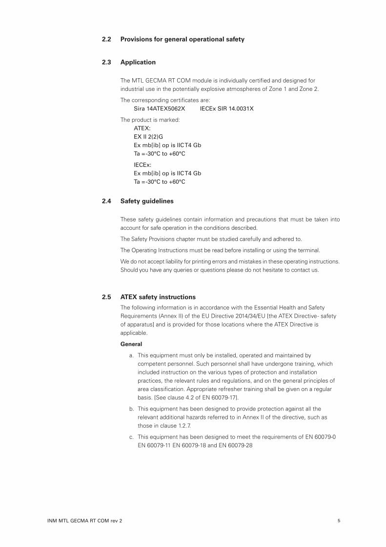
The MTL GECMA RT COM module is individually certified and designed for industrial use in the potentially explosive atmospheres of Zone 1 and Zone 2.
The corresponding certificates are: Sira 14ATEX5062X IECEx SIR 14.0031X
The product is marked: ATEX: EX II 2(2)G Ex mb[ib] op is IIC T4 Gb Ta = -30°C to +60°C
IECEx: Ex mb[ib] op is IIC T4 Gb Ta = -30°C to +60°C
2 .4 Safety guidelines
These safety guidelines contain information and precautions that must be taken into account for safe operation in the conditions described.
The Safety Provisions chapter must be studied carefully and adhered to.
The Operating Instructions must be read before installing or using the terminal.
We do not accept liability for printing errors and mistakes in these operating instructions. Should you have any queries or questions please do not hesitate to contact us.
2 .5 ATEX safety instructions
The following information is in accordance with the Essential Health and Safety Requirements (Annex II) of the EU Directive 2014/34/EU [the ATEX Directive - safety of apparatus] and is provided for those locations where the ATEX Directive is applicable.
General
a. This equipment must only be installed, operated and maintained by competent personnel. Such personnel shall have undergone training, which included instruction on the various types of protection and installation practices, the relevant rules and regulations, and on the general principles of area classification. Appropriate refresher training shall be given on a regular basis. [See clause 4.2 of EN 60079-17].
b. This equipment has been designed to provide protection against all the relevant additional hazards referred to in Annex II of the directive, such as those in clause 1.2.7.
c. This equipment has been designed to meet the requirements of EN 60079-0 EN 60079-11 EN 60079-18 and EN 60079-28
DRAFT - 04 March 2016 DRAFT - 04 March 2016
INM MTL GECMA RT COM rev 26
Installation
a. The installation must comply with the appropriate European, national and local regulations, which may include reference to the IEC code of practice IEC 60079-14. In addition, particular industries or end users may have specific requirements relating to the safety of their installations and these requirements should also be met. For the majority of installations the Directive 1999/92/EC [the ATEX Directive - safety of installations] is also applicable.
b. Unless already protected by design, this equipment must be protected by a suitable enclosure against:
i. mechanical and thermal stresses in excess of those noted in the certification documentation and the product specification ii. aggressive substances, excessive dust, moisture and other contaminants.
Read also the Special Conditions for Safe Use (below) for any additional or more specific information.
Special Conditions of Safe Use for Zone 1 and 2 applications
a. The MTL GECMA RT COM module shall only be powered from an MTL GECMA PSU module, IECEx SIR 14.0030X.
b. The LVDS connector shall only be connected to an MTL GECMA Display module, IECEx SIR 14.0032X.
c. The MTL GECMA RT COM module shall be housed in an enclosure that provides protection against damage to the cables.
d. The MTL GECMA RT COM module enclosure is manufactured from aluminium alloy. In rare cases, ignition sources due to impact and friction sparks could occur. This shall be considered during installation.
e. The intrinsically safe circuit is not isolated from the enclosure; this shall be considered during installation.
Inspection and maintenance
a. Inspection and maintenance should be carried out in accordance with European, national and local regulations which may refer to the IEC standard IEC 60079-17. In addition specific industries or end users may have specific requirements which should also be met.
b. Access to the internal circuitry must not be made during operation.
Repair
a. This product cannot be repaired by the user and must be replaced with an equivalent certified product.
DRAFT - 04 March 2016 DRAFT - 04 March 2016
INM MTL GECMA RT COM rev 2 7
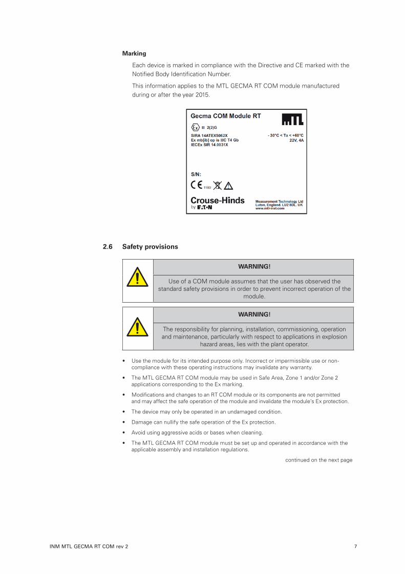
Marking
Each device is marked in compliance with the Directive and CE marked with the Notified Body Identification Number.
This information applies to the MTL GECMA RT COM module manufactured during or after the year 2015.
2 .6 Safety provisions
WARNING!
Use of a COM module assumes that the user has observed the standard safety provisions in order to prevent incorrect operation of the
module.
WARNING!
The responsibility for planning, installation, commissioning, operation and maintenance, particularly with respect to applications in explosion
hazard areas, lies with the plant operator.
• Use the module for its intended purpose only. Incorrect or impermissible use or non- compliance with these operating instructions may invalidate any warranty.
• The MTL GECMA RT COM module may be used in Safe Area, Zone 1 and/or Zone 2 applications corresponding to the Ex marking.
• Modifications and changes to an RT COM module or its components are not permitted and may affect the safe operation of the module and invalidate the module’s Ex protection.
• The device may only be operated in an undamaged condition.
• Damage can nullify the safe operation of the Ex protection.
• Avoid using aggressive acids or bases when cleaning.
• The MTL GECMA RT COM module must be set up and operated in accordance with the applicable assembly and installation regulations.
continued on the next page
DRAFT - 04 March 2016 DRAFT - 04 March 2016
INM MTL GECMA RT COM rev 28
• The equipment must be operated in accordance with the electrical parameters and other information prescribed in the operating instructions and IECEx or EC-type examination certificate.
• All earth connections must be made prior to connection to any power source.
• The installation and commissioning may only be performed by professional personnel who are trained according to the regulations, standards and guidelines applicable here.
• Only devices which correspond to the electrical characteristics of the IECEx or Ectype examination certificate or the operating instructions may be connected.
• The national safety and accident prevention regulations apply.
• Ensure that the RT COM module and any of its associated components have been installed correctly and that any wiring is undamaged before the display is operated.
• The recommended ambient operating temperature range is -10°C <= Ta <= +50°C, however the ambient certified temperature range is -30°C <= Ta <= +60°C.
• The maximum permissible altitude for the operation of the system is 2000 metres.
• All other instructions, notes and regulations contained in these operating instructions must be complied with and observed.
During operation:
• Make these instructions available at all times to the operating personnel.
• Servicing, maintenance work or repairs not described in this manual must not be performed without prior agreement with the manufacturer.
• Avoid using aggressive acids or bases when cleaning.
WARNING!
Operational safety cannot be guaranteed in the event of non-compliance or contravention of these safety provisions and will
invalidate any warranty claim. Deviations require the written approval of GECMA Components
electronic GmbH
2 .7 Errors and overloading
WARNING!
As soon as the safety of a RT COM module has been compromised, it must be taken out of service immediately to avoid any unintended system restarts. We recommend that in this situation the RT COM module should
be removed and returned to the manufacturer for inspection.
The device safety could be compromised if, for example:
• damage to metalwork is visible,
• the device has been subjected to excessive loads,
• the device has been improperly stored,
• the device has been damaged in transit,
• the device certification is illegible,
• malfunctions occur,
• the permissible threshold values have been exceeded.
DRAFT - 04 March 2016 DRAFT - 04 March 2016
INM MTL GECMA RT COM rev 2 9
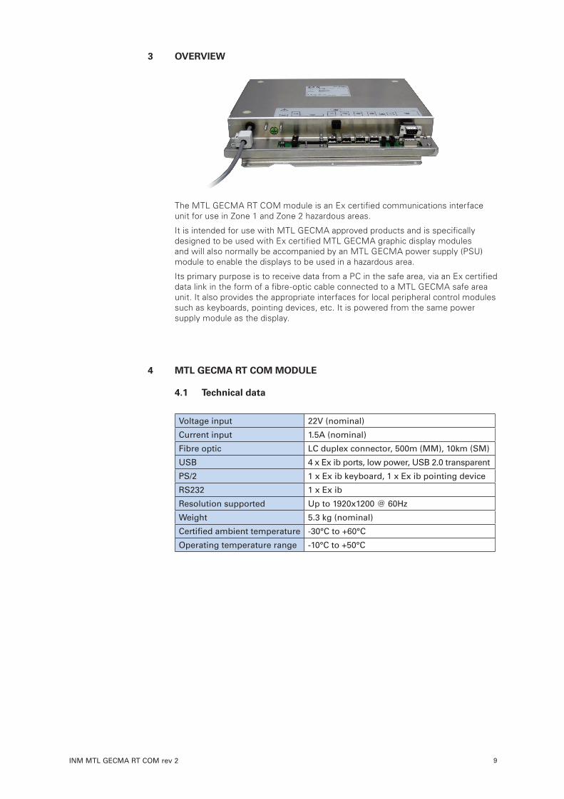
3 OVERVIEW
The MTL GECMA RT COM module is an Ex certified communications interface unit for use in Zone 1 and Zone 2 hazardous areas.
It is intended for use with MTL GECMA approved products and is specifically designed to be used with Ex certified MTL GECMA graphic display modules and will also normally be accompanied by an MTL GECMA power supply (PSU) module to enable the displays to be used in a hazardous area.
Its primary purpose is to receive data from a PC in the safe area, via an Ex certified data link in the form of a fibre-optic cable connected to a MTL GECMA safe area unit. It also provides the appropriate interfaces for local peripheral control modules such as keyboards, pointing devices, etc. It is powered from the same power supply module as the display.
4 MTL GECMA RT COM MODULE
4 .1 Technical data
Voltage input 22V (nominal)
Current input 1.5A (nominal)
Fibre optic LC duplex connector, 500m (MM), 10km (SM)
USB 4 x Ex ib ports, low power, USB 2.0 transparent
PS/2 1 x Ex ib keyboard, 1 x Ex ib pointing device
RS232 1 x Ex ib
Resolution supported Up to 1920x1200 @ 60Hz
Weight 5.3 kg (nominal)
Certified ambient temperature -30°C to +60°C
Operating temperature range -10°C to +50°C

DRAFT - 04 March 2016 DRAFT - 04 March 2016
INM MTL GECMA RT COM rev 210
5 INSTALLATION
5 .1 General information
WARNING!
The ‘Safety guidelines and provisions’ and ‘Installation and Connection Instructions’ must be studied and strictly adhered to in order to ensure
safe and reliable operation.
WARNING!
The installation may only be carried out by trained specialists who have the appropriate training certification. These personnel must be able to demonstrate familiarity with the specific nature of potentially explosive
atmospheres.
WARNING!
All ground connections must be wired prior to commissioning. The connection points are labelled with the symbol shown here on the right.
5 .2 Mechanical installation
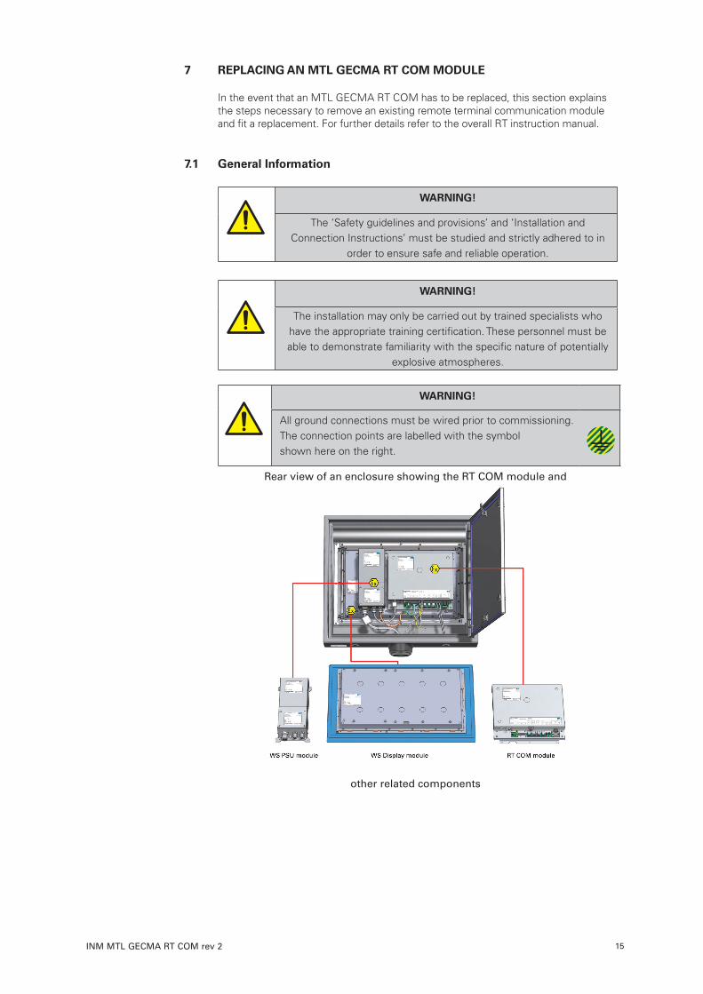
The MTL GECMA RT COM module is designed to fit on the rear panel of the WS display module as shown on the right of the picture below.
Rear view of an enclosure showing the RT COM module and other related components
It is attached via a number of studs that protrude from the back of the display panel. Fit the RT COM module over the studs then fasten it with x6 M4 self locking nuts. Tighten the nuts to the recommended torque value of 1.5-2.0 Nm.
DRAFT - 04 March 2016 DRAFT - 04 March 2016
INM MTL GECMA RT COM rev 2 11
5 .3 Electrical connections
5 .3 .1 DC power connection
The MTL GECMA RT COM module must be powered from an MTL GECMA WS PSU power supply module that is normally fitted alongside the RT COM module as shown in the picture on the previous page ‘5.2 Mechanical Installation’. Refer also to the WS PSU module installation manual.
To connect the MTL GECMA RT COM module to the PSU:
1. Feed the RT COM power cable through the right-hand (M16) cable gland of the PSU.
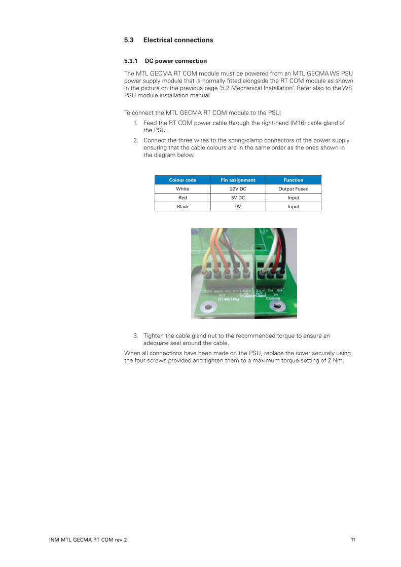
2. Connect the three wires to the spring-clamp connectors of the power supply ensuring that the cable colours are in the same order as the ones shown in the diagram below.
Colour code Pin assignment Function
White 22V DC Output Fused
Red 5V DC Input
Black 0V Input
3. Tighten the cable gland nut to the recommended torque to ensure an adequate seal around the cable.
When all connections have been made on the PSU, replace the cover securely using the four screws provided and tighten them to a maximum torque setting of 2 Nm.
DRAFT - 04 March 2016 DRAFT - 04 March 2016
INM MTL GECMA RT COM rev 212
5 .3 .2 Peripheral equipment connections
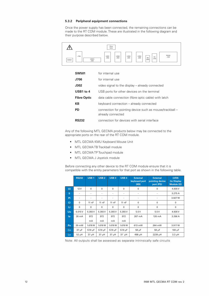
Once the power supply has been connected, the remaining connections can be made to the RT COM module. These are illustrated in the following diagram and their purpose described below.
SW501 for internal use
J706 for internal use
J302 video signal to the display – already connected
USB1 to 4 USB ports for other devices on the terminal
Fibre Optic data cable connection (fibre optic cable) with latch
KB keyboard connection – already connected
PD connection for pointing device such as mouse/trackball – already connected
RS232 connection for devices with serial interface
Any of the following MTL GECMA products below may be connected to the appropriate ports on the rear of the RT COM module.
• MTL GECMA KMU Keyboard Mouse Unit
• MTL GECMA TB Trackball module
• MTL GECMA TP Touchpad module
• MTL GECMA J Joystick module
Before connecting any other device to the RT COM module ensure that it is compatible with the entity parameters for that port as shown in the following table.
RS232 USB 1 USB 2 USB 3 USB 4 External keyboard port
(KB)
External pointing device
port (PD)
LVDS (to Display Module 22)
Ui 12 V 0 0 0 0 0 0 4.935 V
Ii - - - - - - - 3.275 A
Pi - - - - - - - 3.927 W
Ci 0 11 nF 11 nF 11 nF 11 nF 0 0 0
Li 0 0 0 0 0 0 0 0
Uo 6.015 V 5.355 V 5.355 V 5.355 V 5.355 V 5.5 V 5.5 V 4.935 V
Io 26 mA 972
mA
972
mA
972
mA
972
mA
267 mA 126 mA 3.266 A
Po 39 mW 1.676 W 1.676 W 1.676 W 1.676 W 613 mW 264 mW 3.917 W
Co 37 µF 57.9 µF 57.9 µF 57.9 µF 57.9 µF 58 µF 58 µF 100 µF
Lo 52 µH 37 µH 37 µH 37 µH 37 `µH 498 µH 2239 µH 3.3 µH
Note: All outputs shall be assessed as separate intrinsically safe circuits
SW501
J706
VIDEOJ302
USB1J402
USB2J403
USB3J404
USB4J405 KB
J503
PDJ703
RS232J702
FibreOptic
DRAFT - 04 March 2016 DRAFT - 04 March 2016
INM MTL GECMA RT COM rev 2 13
5 .3 .3 Connecting the Data Cable
The data cable is a fibre optic cable with optical transmission (FOC). The advantage of this cable type is in permitting fast, loss-free, data transmission over long distances.
IMPORTANT:
This type of cable will not bend easily and should be handled with care to avoid sharp kinks.
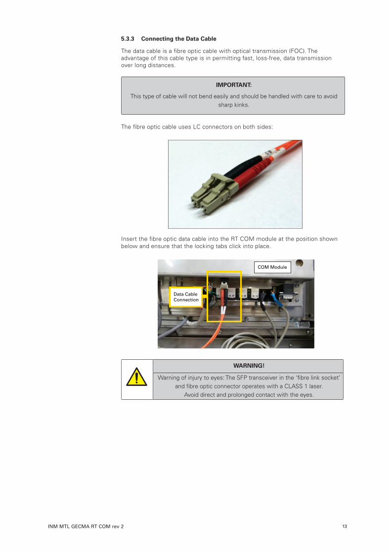
The fibre optic cable uses LC connectors on both sides:
Insert the fibre optic data cable into the RT COM module at the position shown below and ensure that the locking tabs click into place.
WARNING!
Warning of injury to eyes: The SFP transceiver in the ‘fibre link socket’ and fibre optic connector operates with a CLASS 1 laser.
Avoid direct and prolonged contact with the eyes.
Data CableConnection
COM Module
DRAFT - 04 March 2016 DRAFT - 04 March 2016
INM MTL GECMA RT COM rev 214
6 MAINTENANCE At regular intervals, depending upon the particular location of the MTL GECMA RT COM module, the general state of the unit should be assessed for both its electrical and mechanical condition. The following item checks should be considered for inspection. 1. Check for any signs of wear, tampering, or impact damage to the RT COM module. The equipment must be taken out of use immediately if the damage is judged to be affecting its Ex protection. 2. Check all ground (earth) connections for integrity and condition. Check for any signs of corrosion at terminals, and that all screw connections are adequately tightened. 3. Check power connection from the MTL GECMA WS PSU module. If there are signs of wear or cable damage the equipment must be taken out of service immediately and not restored to use until any damaged cables have been replaced. 4. Check the tightness of all mechanical fastenings. 5. Check for the presence or build-up of dust, dirt or contaminants on the module and its surrounding equipment and deal with any accumulations appropriately. 6. Check for any other maintenance issues that may be dictated by site rules. 7. Avoid using aggressive acids or bases when cleaning.
DRAFT - 04 March 2016 DRAFT - 04 March 2016
INM MTL GECMA RT COM rev 2 15
7 REPLACING AN MTL GECMA RT COM MODULE In the event that an MTL GECMA RT COM has to be replaced, this section explains the steps necessary to remove an existing remote terminal communication module and fit a replacement. For further details refer to the overall RT instruction manual.
7 .1 General Information
WARNING!
The ‘Safety guidelines and provisions’ and ‘Installation and Connection Instructions’ must be studied and strictly adhered to in
order to ensure safe and reliable operation.
WARNING!
The installation may only be carried out by trained specialists who have the appropriate training certification. These personnel must be able to demonstrate familiarity with the specific nature of potentially
explosive atmospheres.
WARNING!
All ground connections must be wired prior to commissioning. The connection points are labelled with the symbol shown here on the right.
Rear view of an enclosure showing the RT COM module and
other related components

DRAFT - 04 March 2016 DRAFT - 04 March 2016
INM MTL GECMA RT COM rev 216
7 .2 Removal of the MTL GECMA RT COM module
The picture below provides a view of the electrical and fibre-optic connectors for the RT COM module to be removed.
The diagram below reproduces the label attached to the back of the module adjacent to the connectors can be used to identify and locate the individual
connections provided.
SW501 for internal use
J706 for internal use
J302 video signal to the display – already connected
USB1 to 4 USB ports for other devices on the terminal
Fibre Optic data cable connection (fibre optic cable) with latch
KB keyboard connection – already connected
PD connection for pointing device such as mouse/trackball – already connected
RS232 connection for devices with serial interface
SW501
J706
VIDEOJ302
USB1J402
USB2J403
USB3J404
USB4J405 KB
J503
PDJ703
RS232J702
FibreOptic
DRAFT - 04 March 2016 DRAFT - 04 March 2016
INM MTL GECMA RT COM rev 2 17
7 .3 Removing the existing MTL GECMA RT COM module
IMPORTANT:
Ensure that the power to the terminal is switched off and secured against intentional or unintentional reconnection.
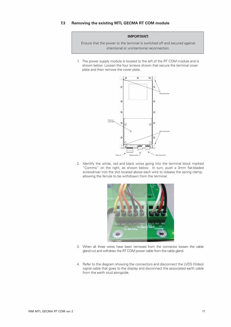
1. The power supply module is located to the left of the RT COM module and is shown below. Loosen the four screws shown that secure the terminal cover plate and then remove the cover plate.
2. Identify the white, red and black wires going into the terminal block marked “Comms“ on the right, as shown below. In turn, push a 3mm flat-bladed screwdriver into the slot located above each wire to release the spring clamp, allowing the ferrule to be withdrawn from the terminal.
3. When all three wires have been removed from the connector loosen the cable gland nut and withdraw the RT COM power cable from the cable gland.
4. Refer to the diagram showing the connectors and disconnect the LVDS (Video) signal cable that goes to the display and disconnect the associated earth cable from the earth stud alongside.
Mounting holes
Mounting holes
Terminalcover plate
Power in Mounting holesDisplay power
DRAFT - 04 March 2016 DRAFT - 04 March 2016
INM MTL GECMA RT COM rev 218
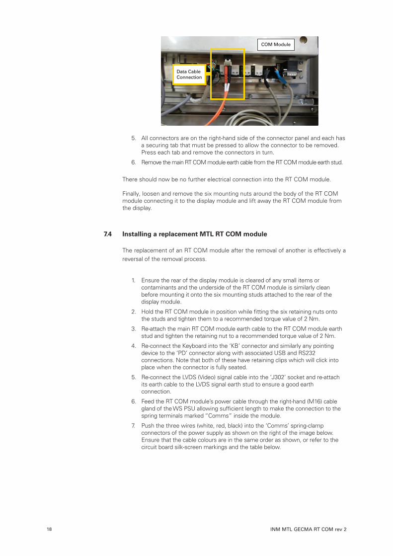
5. All connectors are on the right-hand side of the connector panel and each has a securing tab that must be pressed to allow the connector to be removed. Press each tab and remove the connectors in turn.
6. Remove the main RT COM module earth cable from the RT COM module earth stud.
There should now be no further electrical connection into the RT COM module. Finally, loosen and remove the six mounting nuts around the body of the RT COM module connecting it to the display module and lift away the RT COM module from the display.
7 .4 Installing a replacement MTL RT COM module The replacement of an RT COM module after the removal of another is effectively a reversal of the removal process.
1. Ensure the rear of the display module is cleared of any small items or contaminants and the underside of the RT COM module is similarly clean before mounting it onto the six mounting studs attached to the rear of the display module.
2. Hold the RT COM module in position while fitting the six retaining nuts onto the studs and tighten them to a recommended torque value of 2 Nm.
3. Re-attach the main RT COM module earth cable to the RT COM module earth stud and tighten the retaining nut to a recommended torque value of 2 Nm.
4. Re-connect the Keyboard into the ‘KB’ connector and similarly any pointing device to the ‘PD’ connector along with associated USB and RS232 connections. Note that both of these have retaining clips which will click into place when the connector is fully seated.
5. Re-connect the LVDS (Video) signal cable into the ‘J302’ socket and re-attach its earth cable to the LVDS signal earth stud to ensure a good earth connection.
6. Feed the RT COM module’s power cable through the right-hand (M16) cable gland of the WS PSU allowing sufficient length to make the connection to the spring terminals marked “Comms” inside the module.
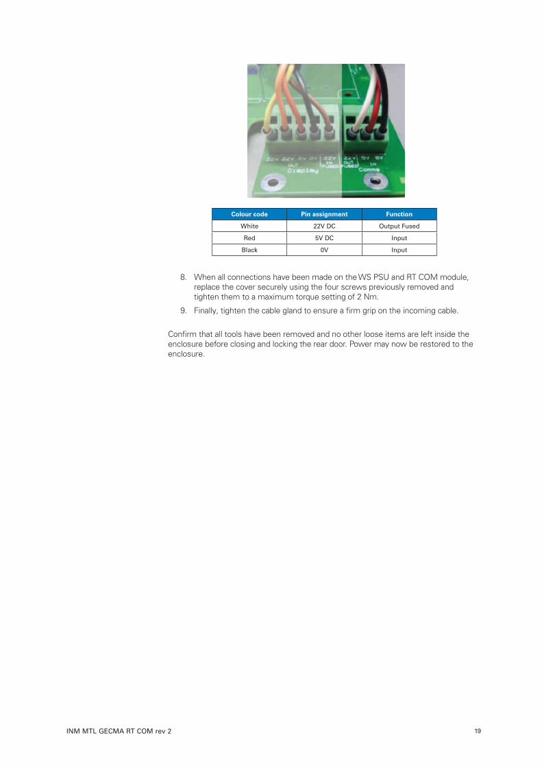
7. Push the three wires (white, red, black) into the ‘Comms’ spring-clamp connectors of the power supply as shown on the right of the image below. Ensure that the cable colours are in the same order as shown, or refer to the circuit board silk-screen markings and the table below.
Data CableConnection
COM Module
DRAFT - 04 March 2016 DRAFT - 04 March 2016
INM MTL GECMA RT COM rev 2 19
Colour code Pin assignment Function
White 22V DC Output Fused
Red 5V DC Input
Black 0V Input
8. When all connections have been made on the WS PSU and RT COM module, replace the cover securely using the four screws previously removed and tighten them to a maximum torque setting of 2 Nm.
9. Finally, tighten the cable gland to ensure a firm grip on the incoming cable.
Confirm that all tools have been removed and no other loose items are left inside the enclosure before closing and locking the rear door. Power may now be restored to the enclosure.
DRAFT - 04 March 2016 DRAFT - 04 March 2016
INM MTL GECMA RT COM rev 220
Appendix A - returns (RMA order)
Dear Customer
Should you find your goods are defective or require a warranty repair, please complete the on-line form on our website at www.gecma.com resources/rma to obtain a RMA reference for the return of your goods Please note that the processing of your return will take longer if goods are sent back to us without a valid RMA number. An RMA number must be included so that your return can be processed quickly and efficiently.
Please have the following information ready:
1. Product name and serial number – you may enter multiple answers where there is more than one product
2. An error description with as much detail as possible
3. Contact information (responsible person(s) and shipping address)
4. If you have submitted the form, you shall receive two emails:
• A confirmation email (IMPORTANT: Please check your junk mailbox)
• An email with the RMA number to be used (this will be sent to you as soon as possible)
Please make the RMA number clearly visible on the package and also include this on the delivery note.
WARNING!
Please ensure prior to returning defective devices that the goods being sent back were not used in areas harmful to health and were cleaned according to the applicable provisions of the Occupational Health and
Safety Act.
Suitable packaging material can be provided for the return for a surcharge.
Please send the goods, with the RMA number clearly visible on the package, to the following address:
Eaton’s Crouse-Hinds divisionGECMA Components electronic GmbHHeinrich-Hertz-Strasse 1250170 Kerpen, Germany
If you require further assistance, please use our product support form, which can be found within the resource section at www.gecma.com, alternatively you can call us on:
+49 (0) 2273 – 9812 – 0
+49 (0) 2237 – 9812 – 364
Thank you
Your Customer Service Department Team

DRAFT - 04 March 2016 DRAFT - 04 March 2016
INM MTL GECMA RT COM rev 2 21
This page is left intentionally blank

DRAFT - 04 March 2016 DRAFT - 04 March 2016
INM MTL GECMA RT COM rev 222
This page is left intentionally blank
DRAFT - 04 March 2016 DRAFT - 04 March 2016
INM MTL GECMA RT COM rev 2 23
This page is left intentionally blank

EUROPE (EMEA):
+44 (0)1582 723633 [email protected]
THE AMERICAS:
+1 800 835 7075 [email protected]
ASIA-PACIFIC:
+65 6 645 9888 [email protected]
The given data is only intended as a product description and should not be regarded as a legal warranty of properties or guarantee. In the interest of further technical developments, we reserve the right to make design changes.
Eaton Electric Limited, Great Marlings, Butterfield, LutonBeds, LU2 8DL, UK.Tel: + 44 (0)1582 723633 Fax: + 44 (0)1582 422283E-mail: [email protected]
© 2016 EatonAll Rights ReservedPublication No. INM MTL GECMA RT COM rev 2 210916September 2016
AUSTRALIAMTL Instruments Pty Ltd, 10 Kent Road, Mascot, New South Wales, 2020, Australia
Tel: +61 1300 308 374 Fax: +61 1300 308 463E-mail: [email protected]
BeNeLuxMTL Instruments BVAmbacht 6, 5301 KW ZaltbommelThe Netherlands
Tel: +31 (0)418 570290 Fax: +31 (0)418 541044E-mail: [email protected]
CHINACooper Electric (Shanghai) Co. Ltd955 Shengli Road, Heqing Industrial ParkPudong New Area, Shanghai 201201
Tel: +86 21 2899 3817 Fax: +86 21 2899 3992E-mail: [email protected]
FRANCEMTL Instruments sarl,7 rue des Rosiéristes, 69410 Champagne au Mont d’OrFrance
Tel: +33 (0)4 37 46 16 53 Fax: +33 (0)4 37 46 17 20E-mail: [email protected]
GERMANYMTL Instruments GmbH, Heinrich-Hertz-Str. 12, 50170 Kerpen, Germany
Tel: +49 (0)22 73 98 12 - 0 Fax: +49 (0)22 73 98 12 - 2 00E-mail: [email protected]
INDIAMTL India, No.36, Nehru Street, Off Old Mahabalipuram RoadSholinganallur, Chennai - 600 119, India
Tel: +91 (0) 44 24501660 /24501857 Fax: +91 (0) 44 24501463E-mail: [email protected]
ITALYMTL Italia srl, Via San Bovio, 3, 20090 Segrate, Milano, Italy
Tel: +39 02 959501 Fax: +39 02 95950759E-mail: [email protected]
JAPANCooper Crouse-Hinds Japan KK, MT Building 3F, 2-7-5 Shiba Daimon, Minato-ku,Tokyo, Japan 105-0012
Tel: +81 (0)3 6430 3128 Fax: +81 (0)3 6430 3129E-mail: [email protected]
NORWAYNorex ASFekjan 7c, Postboks 147, N-1378 Nesbru, Norway
Tel: +47 66 77 43 80 Fax: +47 66 84 55 33E-mail: [email protected]
RUSSIACooper Industries Russia LLCElektrozavodskaya Str 33Building 4Moscow 107076, Russia
Tel: +7 (495) 981 3770 Fax: +7 (495) 981 3771E-mail: [email protected]
SINGAPORECooper Crouse-Hinds Pte LtdNo 2 Serangoon North Avenue 5, #06-01 Fu Yu BuildingSingapore 554911
Tel: +65 6 645 9864 / 5 Fax: +65 6 487 7997E-mail: [email protected]
SOUTH KOREACooper Crouse-Hinds Korea7F. Parkland Building 237-11 Nonhyun-dong Gangnam-gu,Seoul 135-546, South Korea.
Tel: +82 6380 4805 Fax: +82 6380 4839E-mail: [email protected]
UNITED ARAB EMIRATESCooper Industries/Eaton Corporation Office 205/206, 2nd Floor SJ Towers, off. Old Airport Road, Abu Dhabi, United Arab Emirates
Tel: +971 2 44 66 840 Fax: +971 2 44 66 841E-mail: [email protected]
UNITED KINGDOMEaton Electric Ltd, Great Marlings, Butterfield, LutonBeds LU2 8DL
Tel: +44 (0)1582 723633 Fax: +44 (0)1582 422283E-mail: [email protected]
AMERICASCooper Crouse-Hinds MTL Inc. 3413 N. Sam Houston Parkway W.Suite 200, Houston TX 77086, USA
Tel: +1 281-571-8065 Fax: +1 281-571-8069E-mail: [email protected]