instruction manual version 5200 -...
TRANSCRIPT
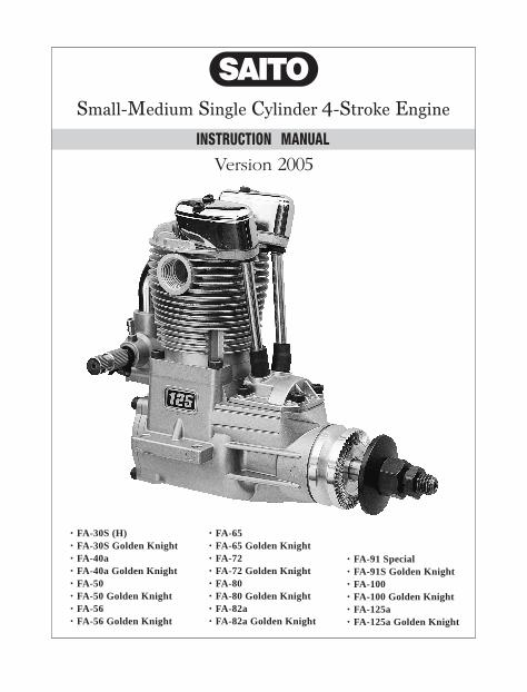
����������� ������ ������� �������� ������
INSTRUCTION MANUAL
Version 2005
. FA-30S (H)
. FA-30S Golden Knight
. FA-40a
. FA-40a Golden Knight
. FA-50
. FA-50 Golden Knight
. FA-56
. FA-56 Golden Knight
. FA-65
. FA-65 Golden Knight
. FA-72
. FA-72 Golden Knight
. FA-80
. FA-80 Golden Knight
. FA-82a
. FA-82a Golden Knight
. FA-91 Special
. FA-91S Golden Knight
. FA-100
. FA-100 Golden Knight
. FA-125a
. FA-125a Golden Knight

VERYIMPORTANT
Failure to readand follow these instructions beforeyou proceed tostart your enginemay result inengine damageand the voiding ofyour warranty.

1S A F E T Y I N S T R U C T I O N S
Introduction
Safety Instructions
You should always:
Congratulations on purchasing a Saito 4-cycle engine. When cared for properly ,these high-quality, finely crafted engines offer many years of modeling enjoyment.
This instruction manual has been developed to ensure optimum performance from the Saito engine you have purchased. The instructions must be read through completely and understood thoroughly prior to mounting and running the engine.
This model engine will give you considerable pleasure, satisfaction, and performance if you strictly follow these safety instructions and take heed of the warnings as to its safe and proper use. Remember at all times it is not a toy, but a precision-built machine with more than enough power to cause harm if misused or if the safety precautions are not observed.
3. Use the correct size and pitchof propeller for your engine, referto the "Propeller Chart" on page 16 of this manual.
4. It is extremely important to balance the propeller prior to installation of the engine. Failure to do so may cause damage to the Saito engine and/or the airframe. Install the propeller with the convex (curved) side facing forward. Securely tighten the propeller out against the washer and propeller. An anti-loosening nut (or “jarn” nut) is suggested for all 4-cycle engines.
5. Inspect the lightness of the propeller nut prior to each flight.
6. Keep your face and body awayfrom the path of the propeller blades when starting or running your engine.
7. Never allow your hands to come close to the propeller. Utilize eithera “Start Stick” or electric starter to start the engine.
8. Discard any propeller that is nicked, scratched, cracked or damaged in any way.
9. Make all carburetor adjustments from behind the propeller.
10. To stop the engine, cut off the fuel supply (pinch or disconnect the fuel line to the carburetor) or use the throttle linkage to shut off the air.
1. Mount the engine securely in a “bench mount” or high-quality motor mount. Never clamp the engine ina vice.
2. When running the engine, be sure all spectators, especially children, are at least 20 feet away.

2 S A F E T Y I N S T R U C T I O N S
Do not use hands, fingers, or any other part of the body to stop the propeller.
Do not throw any object into a propeller to stop it.
. Safety glasses or goggles beused when starting and runningyour engine.
.You do not run the engine in thevicinity of loose gravel or sand. The propeller may throw such materials into your face and eyes. The engine may also ingest these harmful materials.
.Loose clothing should be avoided when operating your model engine. Loose clothing may become entangled in the propeller, creating the possibility of bodily harm. Also, all loose objects (screwdrivers, pencils, nickle cadmium starters, etc.) should be removed from your pockets so that they do not fall into the propeller.
.Glow plug clips and cords are kept away from the propeller.
.Your glow fuel is kept in a safe place well away from sparks, heat, or anything that can ignite the fuel.
It is highly recommended that:
.Model engines get very hot while running. Do not attempt to handle them until they have cooled.
.Always run your model engines in a well-ventilated area. Similar to automotive engines, model engines produce possible harmful carbon monoxide fumes.
.Remember that model engines produce a substantial amount of power, more than enough to seriously injure people and/or do considerable damage to property. Always use common sense, skill and constant observation of safety precautions.
Beware:
DisassemblyDo not needlessly disassemble your Saito engine. Only qualified individuals should perform engine repairs. Damage due to improper disassembly will not be covered under warranty. If it becomes necessary to repair the engine, such as after a crash, you can send your engine to the authorized service center at.
Horizon Hobby, Inc.Attention: Saito Service4105 Fieldstone RoadChampaign, IL 61822Phone: (217) 355-9511

3S U P P O R T E Q U I P M E N T
Engine Parts Identification
Support Equipment
It is important to be able to identify the parts of your Saito engines. Attached you will find an expioded view of a Saito 4-stroke engine, as well as charts that include part numbers and descriptions. This will assist you in easily and rapidly identifying the respective parts of your Saito engine.
The following items, which are not included with your Saito engine, are necessary in order to operate the model engine:
1. Fuel. For maximum protection and loogevity of Saito engines, Saito recommends a fuel containing 20% oil and 10-15% nitro methane. If this blend is not readily available, the next best selection is a high quality 2-cycle glow fuel, such as Hangar 9 Aero-Blend, Omega, Cool Power, K&B, Power Master, etc. Use of fuels composed entirely of castor oil is not recommended. A mix of synthetic-castor oil is acceptable and can be found in the various fuels described above.
4. Glow Plug Wrench. Used to remove and tighten glow plugs. The Hangar 9 Long Reach Plug Wrench (HAN2510) is an excellent wrench to utilize, as a longer shaft may be necessary to access the glow plug. This depends mostly upon engine installation.
5. Manual or Electric Starter. For manual starts, a “Start Stick” is highly recommended. Never use your fingers to start any model engine. To do so invites injury. There are a variety of electric starters on the market. The Hangar 9 (tm) Power Pro Heavy Duty12V Starter (HAN162) will work perfectly on all Saito engines.
6. Tachometer. The use of a tachometer for setting the high-speed needle valve prior to flight is encouraged. It will also be helpful when setting the idle adjustment of the carburetor(s).The Hangar 9 (tm) Micro Digital Tachometer (HAN156) is a good choice.
2. Propeller. Refer to the "Propeller Selection" chart, located on page 16, to determine the best initial propeller for your particular application. Propellers should be balanced prior to use.
3. Glow Plug Battery. Your glow plug may be properly beated by
several different sources. The Hangar 9 Power Panel (HAN106), when accompanied by a 12-volt Sealed Lead Acid Battery (HAN102) and a Glow Plug Locking Socket (HAN120) is an ideal source of heat for your glow plug. A conventional 1.5-volt heavy-duty dry cell battery with a Grow Plug Locking Socket (HAN120) or alligator clips may also be used. Additionally, there are several very good glow-starters (nickel cadmium-powered glow plug igniters) that work well.

4 S T A R T I N G T H E E N G I N E
Break-InThe first run on any engine, whether2-cycle or 4-cycle, is critical to the future of the engine itself. During this time, metal mating parts (piston and cylinder, ball bearings, etc.) wear in. Care must be taken that the engine is clean and free of any dust or grit that may have accumulated while building the model.
There are two accepted methods for breaking in a new engine: test stand mounted and run or aircraft mounted and run. Either method is acceptable: however, mounting the engine to a test stand allows the engine to be observed throughout its operation, as well as elevating it above the ground and away from harmful dust and dirt.
Regardless of the mounting methed chosen for break-in, the following procedures are applicable:
Note: Because your engine may have been sitting for an extended period of time prior to running it, a few drops of light oil applied through the crankcase breather nipple (19 on the exploded view) and down the push-rod tubes (40) will ensure proper lubrication for the first run.
1. Use of a fuel as described in the “Support Equipment” section onpage 3 of this manual for “break-in” purposes is perfectly acceptable.
2. Your engine includes the Saito SS SAIP 400S glow plug. The Hangar 9 (tm) Four Cycle Super Plug (HAN3011) is a standard replacement to use in these engines.
3. To select the correct propeller, refer to the "Propeller Selection" chart on page 16 of this manual. Remember to balance the propeller prior ot use.
4a. For all .30 to .91 engines, ensure that the high speed needle valve (85) is opened (turned counter-clockwise) two and 1/2 turns out. This guarantees a very rich setting.
4b. For all 1.00 to 1.25 engines, ensure that the high speed needle valve (85) is opened (turned counter-clockwise) 5 turns out. This guarantees a very rich setting.
5. The use of a tachometer is highly recommended since the adjustment of a 4-cycle engine, while similar to that of a 2-cycle engine, is more difficult to “set by ear,” making it much easier to damage the engine by “over-leaning.”
Do not adjust the low-speed needle valve (89) at this time. The low-speed needle valve is preadjusted at the factory for initial break-in. Specific instructions for adjusting the idle of engines (FA-30S(H)) using an “air-bleed” type carburetor will be described in the section “Carburetor Adjustments forAir Bleed Carburetors” on page 7.

5S T A R T I N G T H E E N G I N E
Starting The Engine1. Make sure the glow plug(s) is/are installed and tightened.
2. Be sure the propeller is properly secured. The use of an anti-loosening nut, or “jam nut,” is encouraged on 4-cycle engines.
Note: Saito single cylinder engines are now manufactured without the choke valve (92). Due to the excellent fuel draw characteristics of the Saito engines, the use of the choke was determined not to be necessary.
Note: When using an electric starter, care should be taken to be sure the engine does not become “hydro-locked” (flooded with fuel). While the electric starter will turn the engine over, it may damage the connecting rod or other components. If the engine becomes hydro-locked, simply remove the glow plug and turn the engine over a few times with the “Start Stick” or electric starter. The excess fuel will be forced to exit the engine via the cylinder head.
3. Make sure that the fuel tank line(s) are properly connected. The fuel pickup line should be connected to the carburetor spray bar (84), and the vent line should be connected to the pressure nipple on the muffler. The proper “plumbing” of the lines is extremely important to the performance of any engine. Saito recommends the center of the tank be mounted approximately 5 mm lower than the carburetor center.
7. Start the engine:
4. Be certain that the muffler is installed properly by oiling the threads prior to inserting the muffler into the cylinder head and that the pressure line is properly connected.
5. Fill the fuel tank.
6. Prime the engine:
. Check to make sure the glow plug is not connected to the heat source (glow plug clip/locking socket). Open the throttle fully
. Rotate the propeller in a counter- clockwise direction 5 to 6 times while plugging the end of the muffler with your finger to draw fuel into the carburetor.
. Turn through the prop 2 to 3 times slowly to ensure that the engine is not hydro-locked (see note below).
. Colse throttle to 1/4 - 1/3 open position.. Rotate propeller clockwise until it is against the compression stroke.
6 S T A R T I N G T H E E N G I N E
CarburetorAdjustments for TwoNeedle Carburetors
Note: A very common error is to remove the glow plug ingiter too early. It is suggested that the igniter be left attached until after the engine has been run up and the high-speed needle valve has been properly adjusted.
Note: Due to the excessively “rich” mixture setting, it may be necessary to leave the heat source attached to the glow plug.
1. Start the engine and let it warm up prior to attempting any adjustments.
9. After break-in:
Do not exceed 4,000 rpm for the first 10 minutes of operation: This allows all parts to mate properly with good lubrication.
The idle needle valve (89) (or air bleed needle valve) for the Saito .30S(H)/GK engines) may now be refined. Please refer to the "Carburetor Adjustments" section on page 6 for information on how to do so.
The valves may also be checked at this time. Refer to the "Engine Maintenance" section on page 8 for information on the valve/tappet adjustments.
The use of a tachometer is encouraged for setting the high-speed needle valve (85) prior to flight. The peak rpm should be obtained and then reduced by approximately 200 _ 300 rpm by turning the high-speed needle valve counter-clockwise (richen). Each engine’s peak rpm can be found on the "Propeller Chart" on page 16. Over-revving of a 4-stroke engine can cause internal damage to the engine.
The low-speed, or idle needle valve (89), is preadjusted at the factory for best performance during break-in. After break-in it may be necessary to “fine tune” the low speed adjustment using the following procedure:
Subsequent runs may be made while slightly leaning out the mixture with each tank full of fuel. Forty minutes is considered sufficient time for normal break-in prior to the first flight.
If a test stand was used for the break-in procedure, the engine may now be mounted in the aircraft using a high-quality motor mount such as those available from Saito specifically or for Saito engines.
8. Initial break-in:
. Connect the heating source to the glow plug.. Using either the “Start Stick” or electric starter, spin the propeller until the engine is running.

7C A R B U R E T O R A D J U S T M E N T S
CarburetorAdjustments for AirBleed Carburetors
The fuel mixture may be too lean if the engine stops at the lowest idle position, or when the throttle is rapidly opened from idle. Attempt to correct this by rotating the idle needle valve counter-clockwise 1/4 to 1/2 turn at a time until the engine transitions smoothly without hesitation upon opening the throttle rapidly. If the situation is not rectified by counterclockwise rotations of the idle needle valve, turn the idle needle valve clockwise in 1/4 to 1/2
turn increments.
Note: The fuel mixture is too irch if when openning the throttle rapidly the engine emits white smoke and “stutters” or “stumbles.” Correct this by rotating the idle needle valve clockwise 1/4 to 1/2 trun at a time until the engine transitions smoothly without hesitation upon opening the throttle rapidly.
Note: The Saito FA-30S(H) and FA-30SGK use an air bleed carburetor.
Note: The fuel mixture is too rich if when openning the throttle rapidly the engine emits white smoke and “stutters” or “stumbles.” Correct this by rotating the airscrew counter-clockwise 1/4 to 1/2 turn at a time until the engine transitions smoothly without hesitation upon opening the throttle rapidly.
3. After obtaining the proper idle setting, the low rpm setting may be made through the positioning of the throttle adjustment screw, if applicable. If not, adjust the idle setting via the throttle trim of your transmitter.
2. Close the throttle slowly and adjust the low speed setting by rotating the idle needle valve (89) clockwise to lean the mixture and counterclockwise to richen the mixture.
1. Start the engine and let it warm up prior to attempting any adjustments.
2. Close the throttle slowly and adjust the airscrew setting by rotating the airscrew (89) counterclockwise to lean the mixture and clockwise to richen the mixture.
The fuel mixture may be too lean if the engine stops at the lowest idle position or if the engine stops when the throttle is rapidly opened from idle. Attempt to correct this by rotating the airscrew clockwise 1/4 to 1/2 turn at a time until the engine transitions smoothly without hesitatiionupon opening the throttle rapidly. If the situation is not rectified by clockwise rotations of the airscrew, turn the airscrew counter-clockwise in 1/4 to 1/2 turn increments.
8 N O R M A L E N G I N E O P E R A T I O N
Normal EngineOperation
Engine Maintenance
If break-in was accomplished on a test bench your engine may be mounted to the aircraft and flown. The initial flight should be performed with the engine adjusted for a rich fuel mixture.
If you must disassemble your single cylinder engine, please refer to the following steps. Remember, a qualified individual should do disassembly.
3. After obtaining the proper idle setting, the low rpm setting may be made through the positioning of the throttle adjustment screw, if applicable. If not, adjust the idle setting via the throttle trim of your transmitter.
1. Your Saito engine should be securely mounted to the aircraft. There are many motor mounts available; however, a high-quality metal mount, such as those manufactured by Saito exclusively for Saito engines, is considered to be the best.
2. General operating procedures that will ensure long engine life are:
1. Cylinder screws should be loosened in a criss-cross pattern.
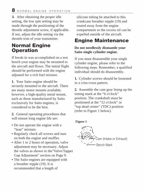
2. Assemble the cam gear lining up the timing mark at the “6 o'clock”position. The crankshaft must be positioned at the “12 o'clock” or “top dead center” (TDC) position (refer to Figure 1 below).
Do not needlessly dismantle your Saito single cylinder engine.
.Do not operate the engine with a “lean” mixture.. Regularly check all screws and nuts on both the engine and muffler.. After 1 to 2 hours of operation, valve adjustment may be necessary. Adjust the valves as shown in the"Valve/Tappet Gap Adjustment" section on Page 9.. The Saito engines are equipped with a breather nipple (19). It is recommended that a length of
silicone tubing be attached to this crankcase breather nipple (19) and routed away from the engine compartment so the excess oil can be expelled outside of the aircraft.
Figure 1
Cam (Intake or Exhaust)
Bench Mark
9E N G I N E O P E R A T I O N
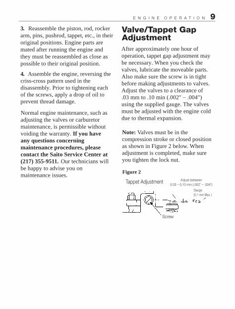
Valve/Tappet Gap AdjustmentAfter approximately one hour of operation, tappet gap adjustment may be necessary. When you check the valves, lubricate the moveable parts. Also make sure the screw is in tight before making adjustments to valves. Adjust the valves to a clearance of .03 mm to .10 min (.002" _ .004") using the supplied gauge. The valves must be adjusted with the engine cold due to thermal expansion.
3. Reassemble the piston, rod, rocker arm, pins, pushrod, tappet, etc., in their original positions. Engine parts are mated after running the engine and they must be reassembled as close as possible to their original position.
4. Assemble the engine, reversing the criss-cross pattern used in the disassembly. Prior to tightening each of the screws, apply a drop of oil to prevent thread damage.
Note: Valves must be in the compression stroke or closed position as shown in Figure 2 below. When adjustment is completed, make sure you tighten the lock nut.
Normal engine maintenance, such as adjusting the valves or carburetor maintenance, is permissible without voiding the warranty. If you have any questions concerning maintenance procedures, please contact the Saito Service Center at (217) 355-9511. Our technicians will be happy to advise you onmaintenance issues.
Figure 2
Tappet Adjustment
Screw
Adjust between
Gauge(0.1 mm Max )
0.03 _ 0.10 mm (.002" _ .004")

10 C A R B U R E T O R M A I N T E N A N C E
Carburetor MaintenanceShould you experience difficulty with the carburetor of your engine:
1. Check that the slotted head of the Idle Needle Valve (89) is flush with the throttle arm housing. This will put the idle needle back to the factory preadjusted position.
2. Remove the high-speed needle (85) and flush out the spray bar with clean fuel. Replace the high-speed needle and follow the instructions in the Carburetor Adjustment section.
3. Always use a high-quality 4-cycle glow plug. Saito SS (SAIP 400S) or Hangar 9(tm) Four-cycle Super Plug (HAN3011) is highly recommended.
Tips For Extended Engine LifeTo add longer life to your Saito engine, the following recommendations are made:
1. Use a high-quality fuel containing 20% lubricauts.
3. Use the proper propeller size and balance the propeller prior to use.
4. Use a tachometer for precise engine adjustments.
5. Use an “after-run” oil when you’re finished flying for the day. Hangar 9 After Run fuel is recommended.
6. For long-term storage, make sure there is no fuel left in the tank and the engine. Remove the glow plug(s) and apply several drops of high-quality light oil (e.g., a good quality light machine oil or Marvel Air Tool Oil) to the top of the engine, into the glow plug hole, down the pushrod tubes, and through the crankcase pressure vent (breather nipple). Rotate the crankshaft several times. Store the engine in the box or on the airplane with the nose down in order to keep oil in the bearings.
2. Use recommended glow plugs.

11T R O U B L E S H O O T I N G
TroubleshootingGenerally speaking, there are very few things that will keep today's modern glow engines from starting. To that end, make sure you're using good quality “fresh” fuel, there are good glow plugs installed, and the starting battery is charged and in good condition. Should the engine fail to start after these items are verified, refer to the following troubleshooting chart on page 12.

12 T R O U B L E S H O O T I N G
SYMPTOM CAUSE CORRECTIVE ACTION
In the event that none of the above procedures results in the engine running properly, contact our service department for suggestions:Horizon Service Center4105 Fieldstone RoadChampaign, Illinois 61822217-355-9511 (Mon-Fri 8:00-5:00 CST)
Engine fails to start
Engine fires butdoes not run
Engine starts but slows down and then stops
Engine quits when starter battery is removed
Engine starts, speeds up, and then quits
Low voltage on starting battery
Bad glow plug(s)
Insufficient priming
“Flooded” due to excessive priming
Over primed
Mixture too rich
Mixture too rich
Incorrect glow plugs
Incorrect or bad fuel
Mixture too lean
Replace/recharge thestarting battery
Inspect/replace bad glow plug
Repeat priming procedure
Disconnect battery, remove the glow plugs, and rotate the propeller several times to “clear” the cylinder
Disconnect battery and rotatepropeller several times to “clear” cylinder
Close high-speed needle valve1/2 turn and start again. Repeat until engine is running smoothly.
Close high-speed needle valve 1/2 turn and restart
Change glow plugs
Chauge fuel
Open high-speed needle valve 1/2 turn and start again. Repeatuntil engine is running smoothly.
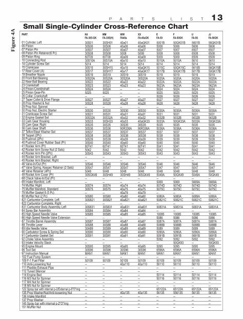
13P A R T S L I S T
Small Single-Cylinder Cross-Reference Chart
Fig
ure
4A
PART NilFA-305-GK
01 Cylinder, Left06 Piston07 Piston Pin08 Piston Pin Retainer(6 Pc)09 Piston Ring10 Connecting Rod14 Cylinder Screw Set15 Crankcase17 Rear Cover (A)19 Breather Nipple20 Front Ball Bearing22 Rear Ball Bearing23 Crankshaft24 Pinion-Crankhshaft25 Pinion Gear-Pin26 Collar, Crankshaft27 Taper Collet & Drive Flange28 Prop Washet & Nut29 Prop Nut, Spinnet30 Prop Nut, Electric Starter31 Crankcase Screw Set32 Engine Gasket Set33 Cam Gear Housing35 Cam Gear, Right36 Cam Gear Shaft37 Teflon/Steel Washer Set38 Tappet (2Pc)39 Pushrod (2Pc)40 Pushrod Cover Rubber Seal (Pr)41 Rocker Arm (Pr)42 Rocker Arm Screw Nut (2 Sets)43 Rocker Arm Pin (2Pc)44 Rocker Arm Bracket, Left45 Rocker Arm Bracket, Right46 Valve-In/Out (Pr)47 Valve Spring, Keeper, Retainer (2 Sets)48 Valve Retainer (4Pc)49 Rocket Arm Cover (Pr)68 Check Valve-In/Out (Pr)69 Intake Manifold, Left74 Muffler, Right75 Muffler Manifold, Standard79 Muffler Gasket 8 (5 Pc)80 Muffler Nut (2 Pc)821 Carburetor-Complete, Left822 Carburetor-Complete, Right831 Carburetor Body Assembly, Left84 Spray Bar Assembly85 High Speed Needle Valve86 High Speed Needle Valve Extension87 Throttle Barrel Assembly88 Throttle Lever89 Idle Needle Valve90 Carbutetor Screw & Spring Set91 Carburetor Gasket Set92 Choke Valve Assembly93 Intake Veloclty Stack95 Engine Mount96 Tool Set97 Instruction Manual102 Fuel Pump System109 F-1 Fuel Filter110 Anti-Loosening Nut111 Flexible Exhaust Pipe112 Tuned Sllencer114 Engine Bed116 M3 Nut for Spinner117 M4 Nut for Spinner118 M5 Nut for Spinner122 Spray bar with internal p-2/External p-5"0"ring135 Prop Washer/Nut/Anti-loosening Nut136 Intake Manifold137 Prop Washer145 Spray bar with internal p-2"O"ring151 Muffler Nut
30S0130S0630S0730S0860T0930S10A501430S1530S1730S1930S20A30S2230S2330S245025–30S2730S28–30S3030S3130S32A30S3330S3530S3630S3730S3830S3930S4060T41504230S43––30S4630S47504830SGK49––30S7430S75–30S8030S821–30S83130S8430S85–30S8730S8830A8930S9030S91––30S9530S96MAN1–50109–––––––––––––
MMFA-30S(H)
30SH0130S0630S0730S0860T0930S10A501430SH1530SH1730S1930S20A30S2230S2330S245025–30S2730S28–30S3030S3130S32A30SH3330S3530S3630S3730S3830S3930S4060T41504230S43––30S4630S47504830SH49––30S7430S75–30S8030S821–30S83130S8430S85–30S8730S8830S8930S9030S91––30S9530S96MAN1–50109–––––––––––––
WWFA40a
40a0140a0640a07500840a0940a10501440a1540a1730S1930S20A40a2240a23–––40a2740a28–30S3040a3140a3240a3330S3590R336A30S3730S3840a3940a4060T41504230S43––30S4630S47504830SH49––40a7440a7540a7940a8040a821–40a83140a8440a85–40a8740a8840a8940a9040a91––40a9530S96MAN1–5010940a110–––––––40a135––––
XXFA-40aGK
40aGK0140a0640a07500840a0940a10501440aGK1540aGK1730S1930S20A40a2240a23–––40a2740a28–30S3040a3140a3240aGK3330S3590R336A30S3730S3840a3940a4060T41504230S43––30S4630S47504830SGK49––40a7440a7540a7940a8040a821–40a83140a8440a85–40a8740a8840a8940a9040a91––40a9530S96MAN1–5010940a110–––––––40a135––––
EFA-50
5001B50065007500850095010A60145015C5017B50195020A5022A5623A50245025502650275628–5030A50315032B5033A50355036A5037503850395040504150425043––5046504750485049A–50695074D5075C–5080A50821C–50831A–1008550865087A5088B50895090A5091B5092–50956596AMAN1–5010956110––5011450116––65122A56135––––
FFA-50GK
50GK01B50065007500850095010A501450GK15C50GK17B50195020A5022A5623A50245025502650275628–5030A50315032B50GK33A50355036A5037503850395040504150425043––50465047504850GK49–50695074D5075C–5080A50821C–50831A–1008550865087A5088B50895090A5091B509250GK9350956596AMAN1–5010956110––5011450116––65122A556135––––
UFA-56
5601B5606650765086509561050145615B5017B50195020A5022A5623A50245025502650275628–5030A50315632B5033A50355036A5037503850395040504150425043––5646504750485049A–5669A5074D5075C–5089A50821C–50831A–1008550865087A5088B50895090A5691B5092–50956596AMAN1–5010956110––5011450116––65122A56135––––
JJFA-56GK
56GK01B56066507650865095610501456GK15B50GK17B50195020A5022A5623A50245025502650275628–5030A50315632B50GK33A50355036A5037503850395040504150425043––56465047504850GK49–5669A5074D5075C–5080A50821C–50831A–1008550865087A5088B50895090A5691B509250GK9350956596AMAN1–5010956110––5011450116––65122A56135––––

14 P A R T S L I S T
Medium Single-Cylinder Cross-Reference ChartF
igu
re 4
B
PART GFA-65
01 Cylinder, Left06 Piston07 Piston Pin08 Piston Pin Retainer (6 Pc)09 Piston Ring10 Connecting Rod14 Cylinder Screw Set15 Crankcase17 Rear Cover (A)19 Breather Nipple20 Front Ball Bearing22 Rear Ball Bearing23 Crankshaft24 Pinion-Crankhshaft25 Pinion Gear-Pin26 Collar, Crankshaft27 Tapered Collet & Drive Flange28 Prop Washet & Nut29 Prop Nut, Spinnet30 Prop Nut, Electric Starter31 Crankcase Screw Set32 Engine Gasket Set33 Cam Gear Housing35 Cam Gear, Right36 Cam Gear Shaft37 Teflon/Steel Washer Set38 Tappet (2Pc)39 Pushrod (2Pc)40 Pushrod Cover Rubber Seal (Pr)41 Rocker Arm (Pr)42 Rocker Arm Screw Nut (2 Sets)43 Rocker Arm Pin (2Pc)44 Rocker Arm Bracket, Left45 Rocker Arm Bracket, Right46 Valve-In/Out (Pr)47 Valve Spring, Keeper, Retainer (2 Sets)48 Valve Retainer (4Pc)49 Rocket Arm Cover (Pr)68 Check Valve-In/Out (Pr)69 Intake Manifold, Left74 Muffler, Right75 Muffler Manifold, Standard79 Muffler Gasket 8 (5 Pc)80 Muffler Nut (2 Pc)821 Carburetor-Complete, Left822 Carburetor-Complete, Right831 Carburetor Body Assembly, Left84 Spray Bar Assembly85 High Speed Needle Valve86 High Speed Needle Valve Extension87 Throttle Barrel Assembly88 Throttle Lever89 Idle Needle Valve90 Carbutetor Screw & Spring Set91 Carburetor Gasket Set92 Chode Valve Assembly93 Intake Veloclty Stack95 Engine Mount96 Tool Set97 Instruction Manual102 Fuel Pump System109 F-1 Fuel Filter110 Anti-Loosening Nut111 Flexible Exhaust Pipe112 Tuned Sllencer114 Engine Bed116 M3 Nut for Spinner117 M4 Nut for Spinner118 M5 Nut for Spinner122 Spray bar with internal p-2/External p-5"0"ring135 Prop Washer/Nut/Anti-loosening Nut136 Intake Manifold137 Prop Washer145 Spray bar with internal p-2"O"ring151 Muffler Nut
6501C6506A6507650865096510C65146515A6517A65196520A6522A6523B–––65275628–5030A50316532B6533B6535A5036A5037503865396540504150425043––6546654750485049A–65696574D8075C–8080A50821C–50831A–1008550865087A5088B50895090A6591B5092–65956596AMAN1–50109561106511165112A–50116651176511865122A56135––––
HFA-65GK
65GK01C6505A6507650865096510C651465GK15A80GK17A65196520A6522A6523B–––65275628–5030A50316532B65GK33B6535A5036A5037503865396540504150425043––65466547504850GK49–65696574D8075C–8080A50821C–50831A–1008550865087A5088B50895090A6591B509250GK9365956596AMAN1–50109561106511165112A–50116651176511865122A56135––––
RRFA-72
8001C8006B91S078008A80097210A651472157217A65196520A6522A7223–––72275628–5030A7231B7232B72336535A7236A503750387239A7240504150425043––6546654750485049A–72696574Çc8075Çb–8080A72821B–72831–10085508672875088B130T8972908091B5092–65956596AMAN1–501009561106511165112A50114–651176511872122A56135––––
SSFA-72GK
80GK01C8006B91S078008A80097210A651472GK157217A65196520A6522A7223–––72275628–5030A7231B7232A72GK336535A7236A503750387239A7240504150425043––65466547504850GK49–72696574D8075C–8080A72821B–72831–10085508672875088B130T8972908091B508250GK9350956596AMAN1–50109561106511165112A50114–651176511872122A56135––––
IFA-80
8001C8006B91S078008A80096510C65148015A6517A651991S20A6522A8023B–––65275628–5030A50318032B6533B6535A5036A5037503865396540504150425043––6546654750485049A–8069A6574D8075C–8080A80321C–80831A–1008550868087A5088B50895090A5091B5092–65956596AMAN1–50109561106511165112A––651176511865122A56135––––
JFA-80GK
80GK01C8006B91S078008A80096510C651480GK15A80GK17A651991S20A6522A8023B–––65275628–5030A50318032B65GK33B6535A5036A5037403865396540504150425043––65466547504850GK49–8069A6574D8075C–8080A80821C–80831A–1008550868087A5088B50895090A8091B509250GK9365956596AMAN1–50109561106511165112A––651176511865122A56135––––
ABFA-B2a
82a01100061000765081000982a10651482a157217A651991S20A91S22A82a23–––72275628–5030A7231B82a3272336535A7236A503750387239A7240504150425043––90S46654750485049A–82a696574D8075C–8080A82a821–82a831–10085–91S87A5088B130T9082a9091S91A––50956596AMAN1–50109561106511165112A––651176511891S122B56135––––
ACFA-82aGK
82aGK01100061000765081000982a10651482aGK157217A651991S20A91S22A82a23–––72275628–5030A7231B82a3272GK336535A7236A503750387239A7240504150425043––91S466547504850GK49–82a696574D8075C–8080A82a821–82a831–10085–91S87A5088B130T8982a9091S91A–50GK9350956596AMAN1–50109561106511165112A––651176511891S122B56135––––
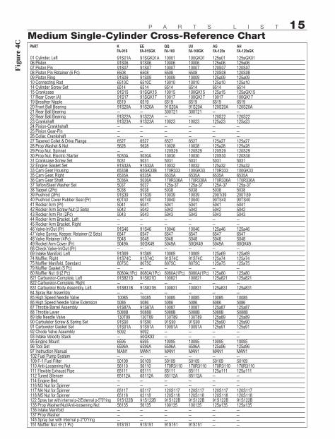
15P A R T S L I S T
Medium Single-Cylinder Cross-Reference Chart
Fig
ure
4C
PART KFA-91S
01 Cylinder, Left06 Piston07 Piston Pin08 Piston Pin Retainer (6 Pc)09 Piston Ring10 Connecting Rod14 Cylinder Screw Set15 Crankcase17 Rear Cover (A)19 Breather Nipple20 Front Ball Bearing21 Rear Ball Bearing22 Rear Ball Bearing23 Crankshaft24 Pinion-Crankhshaft25 Pinion Gear-Pin26 Collar, Crankshaft27 Tapered Collet & Drive Flange28 Prop Washet & Nut29 Prop Nut, Spinnet30 Prop Nut, Electric Starter31 Crankcase Screw Set32 Engine Gasket Set33 Cam Gear Housing35 Cam Gear, Right36 Cam Gear Shaft37 Teflon/Steel Washer Set38 Tappet (2Pc)39 Pushrod (2Pc)40 Pushrod Cover Rubber Seal (Pr)41 Rocker Arm (Pr)42 Rocker Arm Screw Nut (2 Sets)43 Rocker Arm Pin (2Pc)44 Rocker Arm Bracket, Left45 Rocker Arm Bracket, Right46 Valve-In/Out (Pr)47 Valve Spring, Keeper, Retainer (2 Sets)48 Valve Retainer (4Pc)49 Rocket Arm Cover (Pr)68 Check Valve-In/Out (Pr)69 Intake Manifold, Left74 Muffler, Right75 Muffler Manifold, Standard79 Muffler Gasket (5 Pc)80 Muffler Nut (2 Pc)821 Carburetor-Complete, Left822 Carburetor-Complete, Right831 Carburetor Body Assembly, Left84 Spray Bar Assembly85 High Speed Needle Valve86 High Speed Needle Valve Extension87 Throttle Barrel Assembly88 Throttle Lever89 Idle Needle Valve90 Carbutetor Screw & Spring Set91 Carburetor Gasket Set92 Chode Valve Assembly93 Intake Veloclty Stack95 Engine Mount96 Tool Set97 Instruction Manual102 Fuel Pump System109 F-1 Fuel Filter110 Anti-Loosening Nut111 Flexible Exhaust Pipe112 Tuned Sllencer114 Engine Bed116 M3 Nut for Spinner117 M4 Nut for Spinner118 M5 Nut for Spinner122 Spray bar with internal p-2/External p-5"0"ring135 Prop Washer/Nut/Anti-loosening Nut136 Intake Manifold137 Prop Washer145 Spray bar with internal p-2"O"ring151 Muffler Nut (1 Pc)
91S01A91S0691S07650891S096510C651491S1591S17651991S20A–91S22A91S23A–––65275628–5030A503191S32A6533B6535A5036A5037503891S3960T40504150425043––91S46654750485049A–91S6991S74C8075C–8080A(1Pc)91S821D–91S831B–10085508691S87A5088B130T8991S9091S91A5092–65956596AMAN1–50109561106511165112A––651176511891S122B56135–––91S151
EEFA-91SGK
91SGK01A91S0691S07650891S096510C651491SGK1591SGK17651991S20A–91S22A91S23A–––65275628–5030A503191S32A65GK33B6535A5036A5037503891S3960T40504150425043––91S466547504850GK49–91S6991S74C8075C–8080A(1Pc)91S821D–91S831B–10085508691S87A5088B130T8991S9091S91A509250GK9365956596AMAN1–50109561106511165112A––651176511891S122B56135–––91S151
QQFA-100
1000110006100076508100091001065141001510017651991S20A300T21–10023–––652710028120S2910030503110032170R3336535A179R336A125a-3750381003910040504150425043––10046654750485049A–1006991S74C8075C–8080A(1Pc)100821–100831–100855086100875088B130T8991S9010091A––100956596AMAN1–50109170R31106511165112A––120S117120S11891S122B100135–––91S151
UUFA-100GK
100GK011000610007650810009100106514100GK15100GK17651991S20A300T21–10023–––652710028120S2910030503110032100GK336535A170R338A125a-3750381003910040504150425043––100466547504850GK49–1006991S74C8075C–8080A(1Pc)100821–100831–100855086100875088B130T8991S9010091A––100956596AMAN1–50109170R31106511165112A––120S117120S11891S122B100135–––91S151
AGFA-125a
125a01125a06120S07120S08125a09125a106514125a15100176519120S20A–120S22125a23–––125a27125a28120S29120S305031125a32170R3336535A170R336A125A-375038200Ti3990TS40504150425043––125a46654750485049A–125a69125a74125a75–125a80125a821–125a831–100856086125a875088B125a89125a90125a91––10095125a96MAN1–50109170R3110125a111–––120S117120S11891S122B125a135––––
AHFA-125aGK
125aGK01125a06120S07120S08125a09125a106514125aGK15100GK176519120S20A–120S22125a23–––125a27125a28120S29120S305031125a32100GK336535A170R336A125a-375038200Ti3990TS40504150425043––125a466547504860GK49–125a69125a74125a75–125a80125a821–125a831–100855086125a875088B125a89125a90125a91––10095125a96MAN1–50109170R3110125a111–––120S117120S11891S122B125a135––––
1 6 P R O P E L L E R S E L E C T I O N
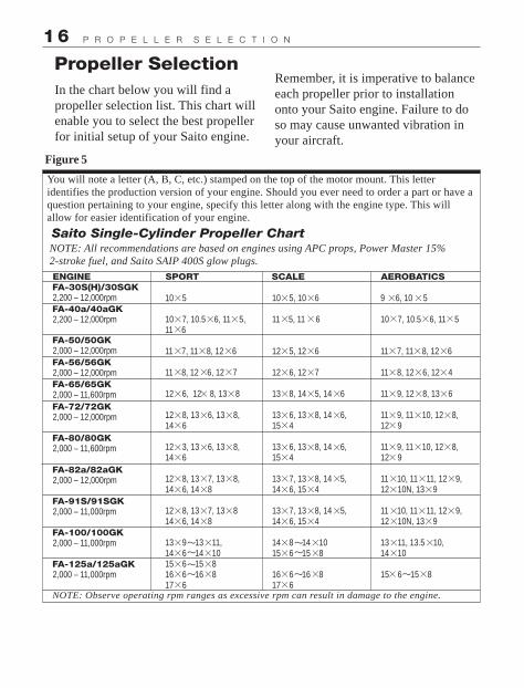
Propeller Selection
Saito Single-Cylinder Propeller Chart
In the chart below you will find a propeller selection list. This chart will enable you to select the best propeller for initial setup of your Saito engine.
You will note a letter (A, B, C, etc.) stamped on the top of the motor mount. This letter identifies the production version of your engine. Should you ever need to order a part or have a question pertaining to your engine, specify this letter along with the engine type. This will allow for easier identification of your engine.
NOTE: All recommendations are based on engines using APC props, Power Master 15% 2-stroke fuel, and Saito SAIP 400S glow plugs.
Remember, it is imperative to balance each propeller prior to installation onto your Saito engine. Failure to do so may cause unwanted vibration in your aircraft.
Figure 5
ENGINE SPORT SCALE AEROBATICSFA-30S(H)/30SGK2,200 – 12,000rpmFA-40a/40aGK2,200 – 12,000rpm
FA-50/50GK2,000 – 12,000rpmFA-56/56GK2,000 – 12,000rpmFA-65/65GK2,000 – 11,600rpmFA-72/72GK2,000 – 12,000rpm
FA-80/80GK2,000 – 11,600rpm
FA-82a/82aGK2,000 – 12,000rpm
FA-91S/91SGK2,000 – 11,000rpm
FA-100/100GK2,000 – 11,000rpm
FA-125a/125aGK2,000 – 11,000rpm
NOTE: Observe operating rpm ranges as excessive rpm can result in damage to the engine.
10 5
10 7, 10.5 6, 11 5,11 6
11 7, 11 8, 12 6
11 8, 12 6, 12 7
12 6, 12 8, 13 8
12 8, 13 6, 13 8,14 6
12 3, 13 6, 13 8,14 6
12 8, 13 7, 13 8, 14 6, 14 8
12 8, 13 7, 13 814 6, 14 8
13 9 13 11,14 6 14 1015 6 15 816 6 16 817 6
10 5, 10 6
11 5, 11 6
12 5, 12 6
12 6, 12 7
13 8, 14 5, 14 6
13 6, 13 8, 14 6,15 4
13 6, 13 8, 14 6,15 4
13 7, 13 8, 14 5,14 6, 15 4
13 7, 13 8, 14 5,14 6, 15 4
14 8 14 1015 6 15 8
16 6 16 817 6
9 6, 10 5
10 7, 10.5 6, 11 5
11 7, 11 8, 12 6
11 8, 12 6, 12 4
11 9, 12 8, 13 6
11 9, 11 10, 12 8,12 9
11 9, 11 10, 12 8,12 9
11 10, 11 11, 12 9,12 10N, 13 9
11 10, 11 11, 12 9,12 10N, 13 9
13 11, 13.5 10,14 10
15 6 15 8
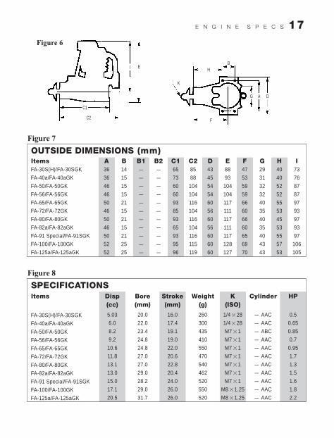
17E N G I N E S P E C S
������ �
������ �
C1
C2
I E
K
HB
F
G A D
OUTSIDE DIMENSIONS (mm)ItemsFA-30S(H)/FA-30SGK
FA-40a/FA-40aGK
FA-50/FA-50GK
FA-56/FA-56GK
FA-65/FA-65GK
FA-72/FA-72GK
FA-80/FA-80GK
FA-82a/FA-82aGK
FA-91 Special/FA-91SGK
FA-100/FA-100GK
FA-125a/FA-125aGK
A36
36
46
46
50
46
50
46
50
52
52
B14
15
15
15
21
15
21
15
21
25
25
B1–
–
–
–
–
–
–
–
–
–
–
B2–
–
–
–
–
–
–
–
–
–
–
C165
73
60
60
93
85
93
65
93
95
96
C285
88
104
104
116
104
116
104
116
115
119
D43
45
54
54
60
56
60
56
60
60
60
E88
93
104
104
117
111
117
111
117
128
127
F47
53
59
59
66
60
66
60
65
69
70
G29
31
32
32
40
35
40
35
40
43
43
H40
40
52
52
55
53
45
53
55
57
53
I73
76
87
87
97
93
97
93
97
106
105
������
SPECIFICATIONSItems
FA-30S(H)/FA-30SGK
FA-40a/FA-40aGK
FA-50/FA-50GK
FA-56/FA-56GK
FA-65/FA-65GK
FA-72/FA-72GK
FA-80/FA-80GK
FA-82a/FA-82aGK
FA-91 Special/FA-91SGK
FA-100/FA-100GK
FA-125a/FA-125aGK
Disp(cc)
5.03
6.0
8.2
9.2
10.6
11.8
13.1
13.0
15.0
17.1
20.5
Bore(mm)
20.0
22.0
23.4
24.8
24.8
27.0
27.0
29.0
28.2
29.0
31.7
Stroke(mm)
16.0
17.4
19.1
19.0
22.0
20.6
22.8
20.4
24.0
26.0
26.0
Weight(g)
260
300
435
410
550
470
540
462
520
550
520
K(ISO)
1/4 28
1/4 28
M7 1
M7 1
M7 1
M7 1
M7 1
M7 1
M7 1
M8 1.25
M8 1.25
HP
0.5
0.65
0.85
0.7
0.95
1.7
1.3
1.5
1.6
1.8
2.2
Cylinder
– AAC
– AAC
– ABC
– AAC
– AAC
– AAC
– AAC
– AAC
– AAC
– AAC
– AAC
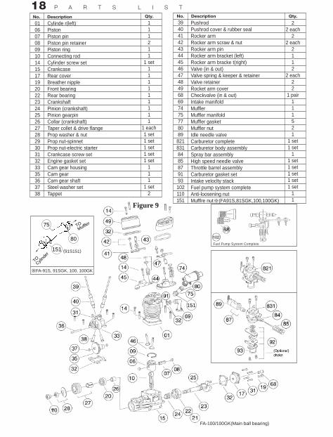
18 P A R T S L I S T
No. Description Qty.
010607080910141517192022232425262728293031323335363738
Cylinde r(left)PistonPiston pinPiston pin retainerPiston ringConnecting rodCylinder screw setCrankcaseRear coverBreather nippleFront bearingRear bearingCrankshaftPinion (crankshaft)Pinion gearpinCollar (crankshaft)Taper collet & drive flangeProp washer & nutProp nut-spinnetProp nut-electric starterCrankcase screw setEngine gasket setCam gear housingCam gearCam gear shaftSteel washer setTappet
111211
1 set111111111
1 each1 set1 set1 set1 set1 set
111
1 set2
No. Description Qty.
394041424344454647484968697475778089
8218318485879193
102110151
PushrodPushrod cover & rubber sealRocker armRocker arm scraw & nutRocker arm pinRocker arm bracket (left)Rocker arm bracke t(right)Valve (in & out)Valve spring & keeper & retainerValve retainerRocket arm coverCheckvalve (in & out)Intake manifoldMufflerMuffler manifoldMuffler gasketMuffler nutIdle needle valveCarburetor completeCarburetor body assemblySpray bar assemblyHigh speed needle valveThrottle barrel assemblyCarburetor gasket setIntake veloclty stackFuel pump system completeAnti-loosening nutMufflre nut (FA91S,81SGK,100,100GK)
22 each
22 each
2112
2 each22
1 pair111521
1 set1 set
11 set1 set1 set1 set1 set
11
Figure 9
75
80
151
151
※FA-91S, 91SGK, 100, 100GK
(91S151)
TOCyli
nder
TOMuffle
r
Fuel Pump System Complete
FA-100/100GK(Main ball bearing)

. Crash damage
. Modifications of any kind
. Nitro content and brand of fuel. Propeller size and brand used. Type of glow plug used. Type of engine mount. Approximately how much running time the engine had before difficulty
19W A R R A N T Y & R E P A I R S
Consumer Warranty and Repair PolicySaito engines are guaranteed against workmanship and manufacturing defects for a period of 3 years from the original date of purchase. This warranty is limited to the original purchaser of the engine and is not transferable. Warranty repairs will not cover:
. Normal engine wear. Damage due to insufficientmaintenance. Damage related to over-revving of engine due to small prop size or unreasonable use
1. Ship your engine in its original box, freight prepaid to:
2. Include a note containing a brief summary of the difficulty and include the following information:
Include complete name and address information inside the carton, as well as clearly writing it on the outer label/return address area.
Date your correspondence and be sure your name and address appear on this enclosure. Also, include a phone number where you can be reached during the business day.
. Damage due to use of improper fueland/or glow plug
. Damage caused by foreign objects (dirt or broken glow plug filaments)
. Damage due to improper disassenibly
. Damage caused by unreasonable mounting or running conditions (dust, insufficient cooling, improper mounting, improper propeller size, or lack of balancing, etc.)
. Damage due to lean runs, such as rusted bearings, seized connecting rod or piston, etc.
. Rusted bearings
If your engine needs repair, please do the following:
Horizon Service CenterAttn: Saito Service4105 Fieldstone RoadChampaign, IL 61822Phone: (217) 355-9511

20 W A R R A N T Y & R E P A I R S
To receive warranty service, you must include your original dated sales receipt to verify your proof-of-purchase date. Providing that warranty conditions have been met, your engine will be repaired without charge.
Please advise us of the payment method you prefer to use. The Horizon Service Center accepts VISA, MasterCard, or money orders. If you prefer to use a credit card, include your card number and expiration date.
The Consumer Warranty Registration in the back of this manual must be completely filled out and mailed to:
Warranty Repairs
Should your repair cost exceed 50% of the retail purchase cost, you will be provided with an estimate advising you of your options. Any return freight for non-warranty repairs will be billed to the consumer.
Non-Warranty Repairs
Horizon Service CenterAttn: Saito Warranty4105 Fieldstone RoadChampaign, IL 61822

Con
sum
er
Warr
an
ty R
egis
trati
on
Com
plet
e th
is f
orm
and
mai
l alo
ng w
ith
your
dat
ed s
ales
rec
eipt
(se
nd c
opy,
kee
p or
igin
al f
or y
our
file
s)
wit
hin
10 d
ays
of p
urch
ase
to:
Ple
ase
cut o
n do
tted
line
Hor
izon
Ser
vice
Cen
ter
Att
n: S
aito
War
rant
y D
ept.
4105
Fie
ldst
one
Roa
dC
ham
paig
n, I
L 6
1822
Eng
ine
Type
Dat
e of
Pur
chas
e
Ow
ner’
s N
ame
Str
eet A
ddre
ss
Cit
y/S
tate
/Zip
Day
tim
e P
hone
Num
ber
Pur
chas
ed F
rom
:
Dea
ler’
s N
ame
Str
eet A
ddre
ss
Cit
y/S
tate
/Zip

Copyright, 2000 Stock #SAIMAN1 updated May 20, 2006SAI.99.36
Exclusively distributed byHorizon Hobby, Inc., Champaign, IL 61822
www.horizonhobby.com
c