instructions for continued …jer/photos/cap/ask-21-n221cp-maint...phone 06658 - 890 \ /...
TRANSCRIPT

2 ~ ALEXANDER SCHLEICHER SEGELFLUGZEUGBAU
0-6416 Poppenhausen /W. - West Germany
Phone 06658 - 890
\ / INSTRUCTIONS FOR CONTINUED
AIRWORTHINESS
SCHLEICHER ASK21 This Manual is
gliders and is
Data Sheet No.
FAA approved for U.S. registered
required by FAA Type Certificate
. ....... Registration: N 2 2 1 C P ...... ....... Factory Serial Number: 2 1 6 6 9 .....................
( )
Owner: ·.............................. ·.............................. ·.... ~ .........................
German edition.of Instru~tions for Continued Air
worthiness are approved under §12(1)2 Luft aerPO
Published: ·.............
Approval of translation has been done by best
ledge and judgement. In any case the original
in German language is authoritative.
know-
text
Instructions For Continued Airworthiness Schleicher ASK 21
1.2 PAGES INCLUDED
cover page 1 March 9, 1983 2 May 4, 1992 3 May 4, 1992 4 March 9, 1983 5 March 9, 1983
I 6 March 9, 1983) 7 March 9, 1983
8 Dec. 20, 1983 9 Dec. 20, 1983 10 March 9, 1983 11 Dec. 20, 1983 12 March 9, 1983 13 March 9, 1983 14 March 9, 1983 15 March 9, 1983 16 March 9, 1983 17 March 9, 1983 18 March 9, 1983 19 March 9, 1983 20 March 9, 1983 21 March 9, 1983 22 March 9, 1983 23 March 9, 1983 24 March 9, 1983 25 May 4, 1992 26 March 9, 1983 27 May 4, 1992 28 March 9, 1983 29 March 9, 1983 30 March 9, 1983 31 March 9, 1983 32 March 9, 1983 33 March 9, 1983 34 May 4, 1992)( 35 May 4, 1992 36 March 9, 1983 37 March 9, 1983 38 March 9, 1983 39 March 9, 1983
40 March 9, 1983 41 March 9, 1983 42 March 9, 1983 43 oct. 16, 1987 44 March 9, 1983 45 oct. 16, 1987 45a oct. 16, 1987 45b May 4, 1992 45c May 4, 1992 45d May 4, 1992 45e May 4, 1992 46 March 9, 1983 47 March 9, 1983 48 March 9, 1983 49 Dec. 20, 1983 50 Dec. 20, 1983 51 Dec. 20, 1983 52 Dec. 20, 1983 53 March 9, 1983 54 March 9, 1983 55 March 9, 1983 56 March 9, 1983 57 March 9, 1983 58 May 25, 1984 59 May 25, 1984 60 oct. 16, 1987 61 May 4, 1992
TN24 dated 04.05.92 (Juw)
\
2

1 20.12.83
," )
CL,i - )
)i1 '
Instruc~ions For continued Airworthines SCHLEICHER ASK 21
I. GENERAL 1.1. Log of Revisions
:Rev. Page 1M. cg;r. Date li).
DescriIX:i.al affected Signature
45 20.12.83 fairlead, 'IN-No. 10 M::xii.ficati.al rel~ cable
sig. by Mr. Fri.eB
2 2, 8, 9, 11 Autanatic elevator cn:uscti.al, 09.03.84 109.03.84 43, 49, SO, sig. by 51.&52
'IN-No. 11 Mr. Fri.eB 'I
3 2 an::i 59 JlJI:uenalBlt to the ManJals in 28.05.84 128.05.~ Erglish ~, '.Il+-No. 14 sig. by
Mr. Fri.eB 'I 4 2, 58 an:! New can:py lcx::ki..rg SyStan, 08.06.84 r08.06.84
S9 sig. by Mr. Fri.eJ3 "
5
'IN-NO. 15
2, 3, 43, 03.11.87 103Qvm;Je/suwlment to the . 11.87 45, 45a., sig. by 45b & 60
Ma.i.nterlance Manual, 'IN-No. 20 Mr. Fri..e13
6 2, 3, 25, 01.10.92MBdlSllt of the Ma.int:erlaD=e 01.10.92 27, 34, 35, sig. by 4Sbto 45e
Manual Inspection progriEl to Mr.SChnal
lam 61 increase the service life, 'IN-Nr. 24 I;ohann
Page No. TN24/04.05~92 Juw Rev.No./Date Si9. Author Date
Kaiser Har.9, 1983 1
2 ~~ ALEXANDER SCHLEICHER SEGELFLUGZEUGBAU
D-6416 Poppenhausen /W. - West Germany
Phone 06658 - 890
/ \ INSTRUCTIONS FOR CONTINUED
AIRWORTHINESS
SCHLEICHER ASK 21 This Manual is FAA approved for U.S. registered
gliders and is requited by FAA Type Certificate
Data Sheet No. . .......
Registration: N 2 2 1 C P ...... ....... Factory Serial Number: 2 1 669..................... Owner: ·..............................
·............................... ..... ................... ......
(, ", ~
German edition,of Instructions for Continued Air
worthiness are approved under §12(t)2 Luft GerPO
Published: ·............
Approval of translation has been done by best know
ledge and judgement. In any case the original text
in German language is authoritative.
Instructions For Continued Airworthiness Schleicher ASK 21
1.2
I )
I
PAGES INCLUDED
Cover page 1 March 9, 1983 2 May 4, 1992 3 May 4, 1992 4 March 9, 1983 5 March 9, 1983 6 March 9, 1983 7 March 9, 1983 8 Dec. 20, 1983 9 Dec. 20, 1983 10 March 9, 1983 11 Dec. 20, 1983 12 March 9, 1983 13 March 9, 1983 14 March 9, 1983 15 March 9, 1983 16 March 9, 1983 17 March 9, 1983 18 March 9, 1983 19 March 9, 1983 20 lofarch 9, 1983 21 March 9, 1983 22 March 9, 1983 23 March 9, 1983 24 March 9, 1983
40 41 42 43 44 45 45a 45b 45c 45d 45e 46 47 48 49 50 51 52 53 54 55 56 57 58 59
March 9, 1983 March 9, 1983 March 9, 1983 oct. 16, 1987 March 9, 1983 oct. 16, 1987 oct. 16, 1987 May 4, 1992 May 4, 1992 May 4, 1992 May 4, 1992 March 9, 1983 March 9, 1983 March 9, 1983 Dec. 20, 1983 Dec. 20, 1983 Dec. 20, 1983 Dec. 20, 1983 March 9, 1983 March 9, 1983 March 9, 1983 March 9, 1983 March 9, 1983 May 25, 1984 May 25, 1984
25 May 4, 1992 60 oct. 16, 1987 26 March 9, 1983 61 May 4, 1992 27 May 4, 1992 28 March 9, 1983 29 March 9, 1983 30 March 9, 1983 31 March 9, 1983 32 March 9, 1983 33 March 9, 1983 34 May 4, 1992) 4, 1992 36 March 9, 1983 37 March 9, 1983 38 March 9, 1983 39 March 9, 1983
f', 35 May
TN24 dated 04.05.92 (Juwl 2
/
Instructions For Continued Airworthiness Schleicher ASK 21 Instructions For Continued Airworthiness SCHLEICHER ASK 21 4
1.3 CONTENTS 1.4 TECHN1CAL DATA
I. General Wing I. 1 1.2 1.3
Log of revisions Pages included Contents
Airfoil Wortmann FX
FX
S02 196
60 -126
(inner wing)
(wingtip) 1.4 Technical Data Span b = 17,00 m = 55,70 ft
II. Description of aircraft and components Area F = 17,95 m 2 = 192,96 sqft
) ,I III.
flI.1 111.2 111.3 111.4
Description of alc assembly and equipment Control systems Landing gear Radio equipment Oxygen equipment
.> Aspect ratio = 16,1
t. = 1,50 m l.
t = 0,50 m a Angle of incidence at root
= 4,92
= 1,67
= +20
ft
ft
111.5 Pressure ports & connections for ~he instruments Dihedral (wing center line) = +40
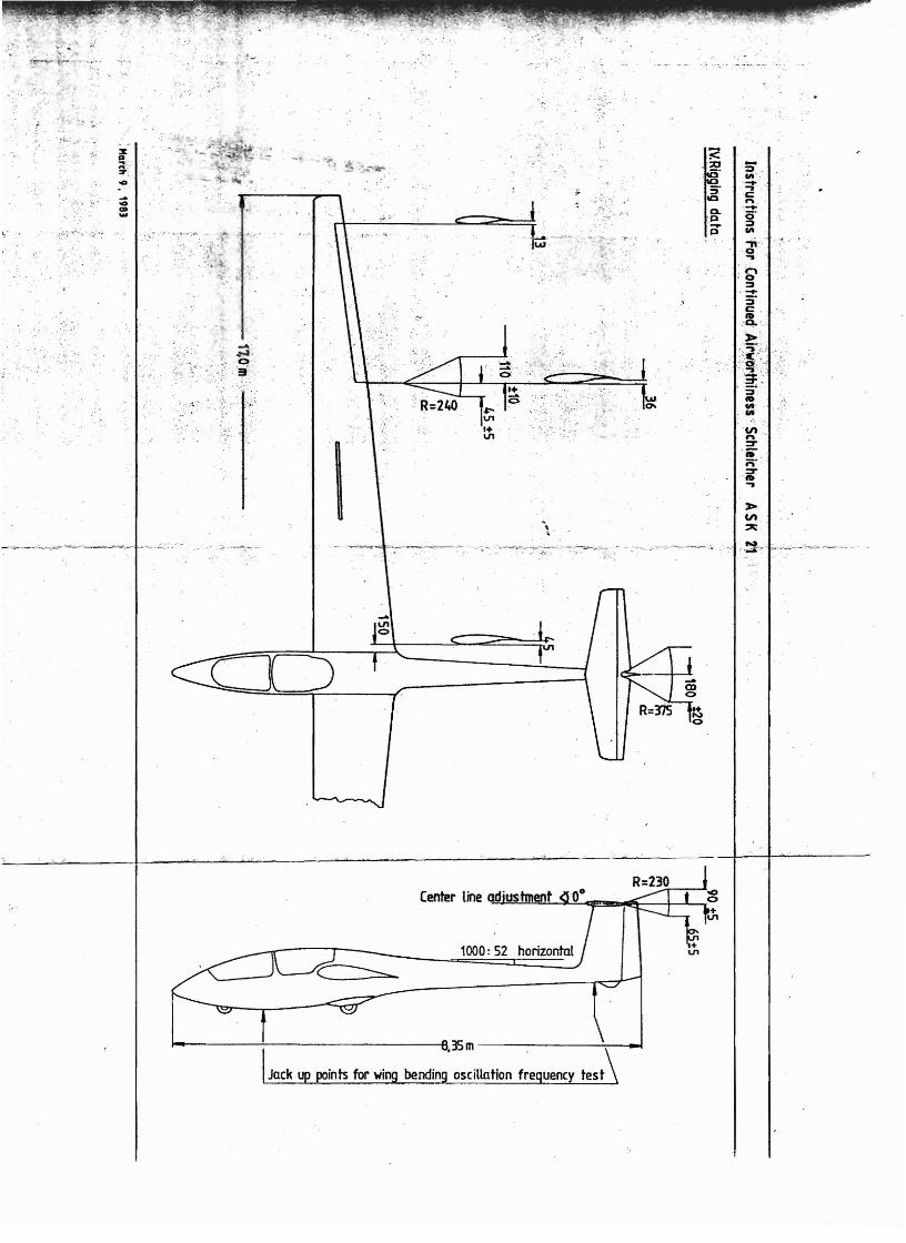
IV. Rigging data Sweep: . iner wing leading edge, straight.
V. Airworthiness Limitation Section Ailerons
VI. VI. 1 VI.2 VI. 3
Weights and C.G. positions Weight and balance sheet C.G .. found at the last weight and Installation of ballast in the tail
balan·ce procedure Span
Area (both)
b Q 2,80 m 1,12 m 2
9,18 ft
12,03 sqft
VI.4
VII.
Weights & tailheavy static
Check Lists
balance of control surfaces..,,,, Inner chord
Outer chord
0,24
0,16
m
m
0,79
0,52
ft
ft
VIII. Periodical inspections Fuselage
IX. Lubrication Scheme Length (rudder included) 8,35 m = 27,40 ft
X.
XI. Repairs
Placards and markings Cockpit width (inner)
Cockpit height
Fuselage wetted area
0,71
1,00
12,33
m
m
m 2
= 2,33 ft
= 3,28 ft
= 132,55 sqft
l, ) XII. Modifications )
XIII. Description of symbolic placards Vertical tail unit
Height above fuselage center line XIV. XIV.1 XIV.2
Appendix Equipment List Maintenance Instructions Area
h = 1,37 m
1,357m2 4,49 ft
14,59 sqft
Aspect ratio 1,383
Upper chord 0,80 m 2,62 ft
TN24 dated 04.05.92 (Juw) 3
March 9, 1983

Instructions For Continued Airworthiness Schleicher ASK 21 Instructions For Continued Airworthiness SCHLEICHER ASK 21 4
1.3 CONTENTS
I. 1.1 1.2 1.3 1.4
General Log of revisions Pages included Contents Technical Data
/)
II.
III. 111.1 111.2 111.3 111.4 111.5
Description of aircraft and components
Description of alc assembly and equipment Control systems Landing gear Radio equipment Oxygen equipment Pressure ports & connections for the instruments
IV. Rigging data
V. Airworthiness Limitation Section
VI. VI. 1 VI.2 VI.3 VI.4
VII.
Weights and C.G. positions Weight and balance sheet C.G. found at the last weight and Installation of ballast in the tail Weights & tailheavy static balance
Check Lists
balarl"ce procedure
of control.... surfaces :
VIII. Periodical inspections
IX. Lubrication Scheme
X. Placards and markings
f, ) XI.
XII.
Repairs
Modifications
XIII. Description of symbolic placards
XIV. XIV.1 XIV.2
Appendix Equipment List Maintenance Instructions
TN24 dated 04.05.92 (Juw) 3
i
'i ,
)
)
1.4 TECHN1CAL DATA
Wing
Airfoil Wortmann FX S02 196 (inner wing)
FX 60 -126 (wingtip)
Span b = 17,00 m = 55,70 ft
Area F = 17,95 m 2 = 192,96 sqft
Aspect ratio = 16,1
t. = 1,50 m ;:: 4,92 ft 1
t = 0,50 m == 1,67 ft a = +2°Angle of incidence at root
Dihedral (wing center line) = +40
Sweep·: . iner wing leading edge, straight.
Ailerons
Span bQ = 2,80 m = 9,18 ft
Area (both) 1,12 m 2 12,03 sqft= = Inner chord = 0,24 m = 0,79 ft
Outer chord = 0,16 m = 0,52 ft
vertical tail unit
Height above fuselage center line
Fuselage
Length (rudder included)
Cockpit width (inner)
Cockpit height
Fuselage wetted area
Area
Aspect ratio
Upper chord
h 1,37 m
1,357m2
1,383
0,80 m
8,35 m 0,71 m
1,00 m ;:: 12,33 m2
4.,49 ft
14,59 sqft
2,62 ft
= 27,40 ft
= 2,33 ft
= 3,28 ft
;:: 132,55 sqft
March 9, 1983

/
Instructions For Continued Airworthiness Schleicher ASK 21
1.3 CONTENTS
I. General 1.1 Log of revisions 1.2 Pages included 1.3 Contents 1.4 Technical Data
II. Description of aircraft and components I' )
111. Description of alc assembly and equipment 111.1 Control systems 111.2 landing gear 111.3 Radio equipment 111.4 Oxygen equipment 111.5 Pressure ports & connections for the instruments
IV. Rigging data
V. Airworthiness limitation Section
VI. Weights and C.G. positions VI. 1 Weight and balance sheet VI.2 C.G. found at the last weight and balan·ce procedure VI.3 Installation of ballast in the tail VI.4 Weights & tailheavy static balance of control,.,. surfaces
VII. Check Lists
VIII. Periodical inspections
IX. Lubrication Scheme
X. Placards and markings
XI. Repairs
( ) XII. Mod ifications
XIII. Description of symbolic placards
XIV. Appendix XIV.1 Equipment List XIV.2 Maintenance Instructions
TN24 dated 04.05.92 (Juw) 3
j -
1\' ,
,)
)
4Instructions For Continued Airworthiness SCHLEICHER ASK 21
1.4 TECHNICAL DATA
Wing
Airfoil Wortmann FX S02 196 (inner wing)
FX 60 -126 (wingtip)
Span b = 17,00 m = 55,70 ft
Area F = 17,95 m2 = 192,96 sgft
Aspect ratio = 16,1
t. = 1,50 m = 4,92 ft ~
t = 0,50 m :;: 1,67 ft a Angle of incidence at root :;: +20
Dihedral (wing center line) = +40
Sweep: , iner wing leading edge, straight.
2,62 ft
9,18 ft
12,03 sqft
0,79 ft
0,52 ft
8,35 m = 27,40 ft
0,71 m :;: 2,33 ft
1,00 m = 3,28 ft
12,33 m 2 = 132,55 5gft
4,49 ft
14,59 sgft
2,80 m
1,12 m 2
0,24 m
0,16 m
b Q
Area
Height above fuselage center line
h = 1,37 m
1,357m2
1,383
0,80 m
Vertical tail unit
Aspect ratio
Upper chord
Ailerons
Span
Area (both)
Inner chord
Outer chord
Fuselage
Length (rudder included)
Cockpit width (inner)
Cockpit height
Fuselage wetted area
March 9, 1983

2 ~ ALEXANDER SCHLEICHER SEGELFLUGZEUGBAU
D-6416 Poppenhausen /W. - West Germany
Phone 06658 - 890
/ ') INSTRUCTIONS FOR CONTINUED
AIRWORTHINESS
SCHLEICHER ASK21 This Manual is FAA approved for U.S. registered
gliders and is required by FAA Type Certificate
Data Sheet No. . ....... Registration: N 2 2 1 C P ...... ....... Factory Serial Number: 2 166 9..................... Owner: ·..............................
·............................... • •••• II • ••••••••••••••••••••••••
( \,
) German edition,of Instru~tions for Continued Air
worthiness are approved under §t2(t)2 Luft GerPO
Published: ·.............
Approval of translation has been done by best know
ledge and judgement. In any case the original text
in German language is authoritative.
Instructions For Continued Airworthiness Schleicher ASK 21
1.2 PAGES INCLUDED
Cover page 1 March 9, 1983 2 May 4, 1992 3 May 4, 1992 4 March 9, 1983 5 March 9, 1983
I 6 March 9, 1983) 7 March 9, 1983 8 Dec. 20, 1983 9 Dec. 20, 1983 10 Mard1 9, 1983 11 Dec. 20, 1983 12 March 9, 1983 13 Mard1 9, 1983 14 March 9, 1983 15 March 9, 1983 16 March 9, 1983 17 March 9, 1983 18 March 9, 1983 19 March 9, 1983 20 March 9, 1983 21 March 9, 1983 22 March 9, 1983 23 March 9, 1983 24 March 9, 1983 25 May 4, 1992 26 March 9, 1983 27 May 4, 1992 28 March 9, 1983 29 March 9, 1983 30 March 9, 1983 31 March 9, 1983 32 March 9, 1983 33 March 9, 1983 34 May 4, 1992)(. 35 May 4, 1992 36 March 9, 1983 37 March 9, 1983 38 March 9, 1983 39 March 9, 1983
40 March 9, 1983 41 March 9, 1983 42 March 9, 19$3 43 oct. 16, 1987 44 March 9, 1983 45 oct. 16, 1987 45a oct. 16, 1987 45b May 4, 1992 45c May 4, 1992 45d May 4, 1992 45e May 4, 1992 46 March 9, 1983 47 March 9, 1983 48 March 9,1983 49 Dec. 20, 1983 50 Dec. 20, 1983 51 Dec. 20, 1983 52 Dec. 20, 1983 53 March 9, 1983 54 March 9, 1983 55 March 9, 1983 56 March 9, 1983 57 March 9, 1983 58 May 25, 1984 59 May 25, 1984 60 oct. 16, 1987 61 May 4, 1992
TN24 dated 04.05.92 (Juw) 2

!
Instructions For Continued Airworthiness Schleicher ASK 21 Instructions For Continued Airworthiness SCHLEICHER ASK 21 4
1.3 CONTENTS
I. General 1.1 Log of revisions 1.2 Pages incJuded 1.3 Contents 1.4 Technical Data
II. Description of aircraft and components
./) III. Description of ale assembly and equipment 111.1 Control systems 111.2 Landing gear 111.3 Radio equipment 111.4 Oxygen equipment 111.5 Pressure ports & connections for the instruments
IV. Rigging data
V. Airworthiness Limitation Section
VI. Weights and C.G. positions V1.1 Weight and balance sheet VI.2 C.G. found at the last weight and balance procedure VI.3 Installation of ballast in the tail VI.4 Weights & tailheavy static balance of control surfaces
... VII. Check Lists
VIIJ. Periodical inspections
IX. Lubrication Scheme
X. Placards and markings
XI. Repairs
/, ) XII. Modifications
XIII. Description of symbolic placards
XIV. Appendix XIV.1 Equipment List XIV.2 Maintenance Instructions
TN24 dated 04.05.92 (Juw) 3
)
)
1_4 TECHNICAL DATA
Vertical tail unit
Height above fuselage center line
ft
sqft
2,62 ft
4",49 ft
14,59 sqft
8,35 m
0,71 m
1,00 m 212,33 m
4,92 ft
1,67 ft
+2 0
+40
straighL
9,18 ft
12,03 sqft
0,79 ft
0,52 ft
(inner wing)
(wingtip)
m = 55,70
m 2 = 192,96
1,37 m
1,357m2
1,383
0,80 m
2,80 m
1,12 m 2
0,24 m
0,16 m
h
b Q
F
.b
Aspect ratio
Area
Area
Aspect ratio
Upper chord
Fuselage
Length (rudder included)
Cockpit width (inner)
Cockpit height
Fuselage wetted area
Ailerons
Span
Area (both)
Inner chord
Outer chord
Wing
Airfoil Wortmann FX
FX
Span
S02 196
60 -126
17,00
17,95
16,1
t i = 1,50 m
t a = 0,50 m
Angle of incidence at root
Dihedral (wing center line)
Sweep": . iner wing leading edge,
27,40 ft
2,33 ft
3,28 ft
132,55 sqft
March 9, 1983

Instructions For Continued Airworthiness SCHLEICHER ASK 21 5
Lower chord = 1,17 m 3,84 ft
Airfoil Wortmann FX 71-L-150/30.
Rudder
33 % of vertical tail unit chord
Area = 0,45 2 m 4,86 sqft
( ) Chord (middle) = 0,33 m 1,08 ft
Horizontal tail unit
Span
Area
3,1
1,92
m m 2
10,16 ft
20,64 sqft
Aspect ratio 5,05
Elevator
Area = 20,5 76m = 6,19 sqft
30,1 % of horizontal tail unit chord
Airbrakes
Schempp-Hirth type, on upper wing only.
Area 0,35 m 2 3,77 sqft
Span 1,35 m 4,43 ft
Height 0,13 m 0,43 ft
Weights • ) Max all up weight 6QO daN 1320 Ibs
Empty weight, app. 370 daN 814 lbs
Weight of non 11ft
producing parts 410 daN = 902 Ibs
Max wing loading 33,4 daNm 2 = 6,84 Ibssqft
Max load of occupants, luggage, etc.
see load table in the Flight Manual.
Instructions For Continued Airworthines. SCHLEICHER ASK 21 6
<'
\
)
II. DESCRIPTION OF AIRCRAFT AND COMPONENTS
Aircraft
The ASK 21 is a two-seater midwing with T-tail, airbrakes,
fixed shock absorbing main wheel and a nose wheel.
The structure is made in a highly developped fiberglass
technology. On certain critical areas carbon fibers are
used.
Wing
Double T spar made of fiberglass roving flanges and fi
berglass cloth webs. The skin consists of a 9mm Conticell
core with fiberglass on both sides.
Easy wing assembly by tongue and fork connection, fixed
by two 36¢ bolts. Two shear bolts at the fuselage which
fit the bushings in the wing center rib, absorb the shear
loads to the fuselage. The rear· shear bolts are secured
by an automatic safety device.
Fuselage
The fuselage is designed as a honeycomb (tubus core) con
struction throughout which means consider~ble increase of
strength compared to non sandwich shells.
2-piece canopy, forward hinged in front and rearward hinged
in back; adjustable back rests •
Tailplane
T-tail consisting of the same construction as the wing.
Control Surfaces
Sandwich construction with Rohacell foam core.
111.1
III.
CONTROL SYSTEMS
General
Except for the rudder which is operated by
DESCRIPTION OF AIC ASSEM8LY & EQUIPMENT
cables'
I~'
March 9, 1983 l\ ~.. March 9, 1983 I I I !
\ \
\

8 Instructions For Continued Airworthiness SChleicher ASK 21 7
Instructions For Continued Airworthiness Schleicher ASK 21
)
)
Control Systems
March 9, 1983
e e EJ!! ... Q/ lIt~~ >..IIII11C lit ~ i:i'.2-eocs ~ c ~J::J::.2ace"" u 0 0 c
"" u
.e~lii~t ~ ~:g ~.; w<a::<t==
I I I I
the whole control system is actuated by pushrods. The long push rods are 16 0 x 1,0 mm aluminium with ball bearing SUPports. The cockpit controls and the shorter pushrods are welded steel. The control system levers are milled duraluminium or welded steel. Elevator control system
) Both control sticks are bUilt as 2-armed levers and feature universal Joints. The control sticks are linked together by a main steel tube torsion rod at the bottom. This torsion rod features at its front and rear end an adjustable stop for both control sticks. Another bent steel tube torsion rod leads from the rear control stick to a combined elevator/aileron rocker arm. From there a short aluminium pushrod leads to a 180 0 duraluminium bellcrank which is linked UP by a long aluminium pushrod which runs through 4 support bearingS; the support bearings consist of a fiberglass bracket with 3 ball bearings. Via a 90 0 duraluminium bellcrank, the control forces are lead upwards into the fin using a fiberglass plastic pushrod. Here connects a 1800 duraluminium bellcrank to a short aluminium pushrod which in turn connects to a M12.41/HOTELLIER Joint which operate~ the elevator. Elevator with automatic connection: Instead of the aluminium pushrod, an actuating pushrod is in
) stalled, which is supported with a parallel rocker.
Trim
The trim is spring susoended and consists of 2 trim levers, 1 connecting Pushrod and the 2 trim springs with slotted gate sheet metal. The trim levers are connected to the control sticks with a knurled nut at the control stick bearing bolt. AfrIction brake is tightened with this knurled nut at the control stick
December 20, 1983 TN nO.11

..
~ I
U i
~
\ ','---- Instructions Fot Cont;'
automatic elevator connection TN no.11
Dlcember 20, 1983 TNno.11
t

10
.,'
Trim lever rear
stick
;
I"! .....
~ick front
Instructions For Continued Airworthiness Schleicher ASK 21
.';~~ .
.
stick assembly and Trim system
..
March 9. 1983

Instructions For Continued Airworthiness Schleicher ASK 21 11
bearing bolt. The braking force should be distributed evenly between the front and rear brake. The brake should be tightened so strong that even with extremelY opposed Positions of sttck and trim leverl the trim will not move. The trim connecting pushrod features a stop at it~ front and rear end. The springs with the adjusting plate between theml are sus
J} pended into the 2 rings of the front control shaft. The adjusting plate itself is mounted to the bolt of the trim connecting pushrod; here the trim may be adjusted. The trim should be adjusted such that With 1 pilot and the trim ~et full forward l a trimmed speed of 150-160 km/h (81-86 1 3 kts; 9312-9914 mph) is reached; then the trim lever is in a slightly forward position when the stick is free and in its center position (elevator connected). To adjust the trim roughly to a trimmed soeed of max. 160 km/h (86 13 kts; 9914 mph): 1. Connect elevator.
(This is inapplicable when your glider features the automatic elevator connection).
2, Adjust the trim spring such that the stick is set to the above-mentioned relative position to the trim lever. Friction must be balanced by Hfeellng for H the center position.
Trim indicator t'
In addition to the VIsible position of the trim lever itselfl the trim features a trim indicator. The trim indication should be in the center position when the trim lever is vertical to the glider's longitudinal axis. It can be adjusted by ooening the clamp at the trim connecting pushrod and by displacing the Bowden cable. Then retighten the clamo.
Instructions For Continued Airworthiness Schleicher ASK 21 12
Trim "Basic Adjustment
)
Front
\ J
·rDecember 201 1983 TN nO.11

----------
14 Instructions For Continued Airworthiness SCHLEICHER ASK 21 13
Aileron control system
A short aluminum pushrod leads from the horizontal
aileron control system lever at the rear elevator/
aileron control system torsion rod upwards to a 90 0
du.aluminum bellcrank in the fuselage. By a HOTELLIER
joint (M12.41) follows from here the long aluminum
) pushrod in the wing. This pushrod is supported alto
gether seven times in each three ball bearings. Por
the compensation of the bellcrank travels short steel
tube pushrods are articulated by ball bearings (14C6)
at both ends of the long pushrod. The inner short
pushrbd features the HOTELLIER connection with the ad
justing screw. At the 90 0 duraluminum bellcrank the
aileron pushrod actuates the aileron through a HIRSCH
MANN-UNIBAL adjustable head (SMx CP6).
The st'ops for the aileron are positioned in the push
rod box in front of the rear stick. These are two ply
wood blocks glued into the pushrod box and cut out such
that they stop laterally the travel of the front tor
sion shaft.'
)
Instructions For Continued Airworthiness Schleicher ASK 21
..:.: c
@C... ~I @Q.l .0
C
) ~ ~
<c o
\~ O't C 'j
C1I ..c +c:
E Q.l+VI >VI
o....... c: o u
c /G E
"" .'\.\ ..- :.:{ 'p ~
~
\d
\~B
;~)
f"1a~ch 9, 1:J83f"1c.irch '), 198::'

16 Instructions For Continued Airworthiness SCHLEICHER ASK 21 15
Rudder control system
The rudder is actuated by cable (3,20 LN 9374).
Both front and rear pedals are adjustable. The rudder
cables are running from a fixed point through S-type
pe~al loops to an adjusting plate in the rear cockpit.
Here are joined together the cables from the front) and rear pedals. From the adjusting plate the cables
run through nylon tubes to the rudder-actuating lever.
At the adjusting plate slight inaccuracies in
the cable length maybe adjusted and also the pedal in
clination. The cables are held taut by springs at the
pedals; at the rear pedals this spring serves simul
taneously for holding down the adjusting stop.
For the adjustment of the cables at the adjustment plate
the rear seat must be removed.
The stop forthe rudder is located in the back of the
rudder.
The rudder lever strikes a stop at the bearing bracket •
., I
Instructions for Continued Airworthiness Schleicher ASK 21
)
.-,,~~
\
Front Pedals
I March 9, 1983March 9, 1983
I
~

Instructions For Continued Airworthiness Schleicher ASK 21 17
t )
)
:gVI
QJ a.. L..,
d QJa:
)
Instructions For Continued Airworthiness SCHLEICHER ASK 21 18
Airbrakes
The airbrakes are actuated by pushrods.On the left
cockpit wall runs a connecting rod with a handle each
for the front and rear cockpit. In the front cockpit
the rod is running in a nylon guide, in the rear cock
) pit it is supported by a duraluminum rocker arm. From
this arm another pushrod - placed under the arm - con
tinues to a 900 duraluminum bellcrank and runs below
the rear spar tunnel wall.
The back of the spar tunnel wall features two rocker
arms and the pushrod which produces the counterclock
wise travel of the actuating levers. By a HOTELLIER
joint (M12.41) the pushrods in the wing are connected
to the actuating levers. They run through three ball
bearing guides and lead to the airbrake toggle joint
lever.
A short pushrod leads to the inner airbrake lever which
on the other hand is connected to the outer air;:brake lever
by a pushrod so that synchronous movement is guaranteed.
stop of the airbrake control: Brake cylinder.
)
March 9, 1983 March 9, 1983

Instructions For Continued Airworthiness Schleicher ASK 21 19 Instructions For Continued Airworthiness Schleicher ASK 21 20
c: 0
:+: u OJ c: c: 0
~l ~~ /@
x e .a L..
<. @
, -
\ II I ~;; [ . \. ",,-II\.'\.
~ <::l
~ ----@ v-x "
"'6
f !
~~ "x?
~
)
OJ en 0 OJ
111 ::J-OJ• .c.... .5 E OJ
04II)
>. I/)
QI ..:II:: C c... .a
«c...
)
I )
en{I'(j 'j c::
~~ OJ
)
..c::......
.5 e OJ.... V)
~ <
>.
OJ
V)
x E .a L..
March 9, 1983 March 9, 1983

Instructions For Continued Airworthiness SCHLEICHER ASK 21 21
III. 2 LANDING GEAR
The landing gear consists of the shock absorbing main
wheel 5.00-5 and the non shock absorbing nose wheel
4.00-4. The trailing boom main wheel uses two hollow
type rubber shock absorbers (type KE 120/95 core A
with mounting member, quality RTK 55).) The rim is a Cleveland wheel 4078 (B), 5.00-5 Type III!
Brake: Cleveland brake assy 30-9.
Main brake cylinder: Master cylinder 10-20.
Tank for brake fluid: Below rear seat pan on LH side.
Main wheel: Tire with tube 5.00-5,
6ply rating.
Nose wheel: Tire with tube 4.00-4,
4ply rating.
Tire pressure
Main wheel 2,7 bar 38 psi.
Nose wheel 2,0 bar 28 psi.
To fill up the brake
Brake fluid: ESSO UNIVIS J-13 or
AEROSHELL fLUID 4) You absolutely have to observe that only brake fluid
on a mineral oil basis ~s used.
Car brake fluid on ester basis will destroy gaskets
and tubes in a very short time.
March 9, 1983
Instructions For Continued Airworthiness SCHLEICHER ASK 21 22
fOR TAILWHEEL OPTION ONLY
III. 2 LANDING GE:AR
)
The landing gear consists of the shock absorbing main
wheel 5.00-5 and the non shock absorbing nose wheel
4.00-4. The trailing boom main wheel uses two hollow
type rubber shock absorbers (type KE 120/95 core A
with mounting member, quality RTK 55).
The rim is a Cleveland wheel 4078 (B), 5.000-5 Type III.
Brake:
Main brake cylinder:
Tank for brake fluid:
Main wheel:
Nose wheel:
Tail wheel:
Cleveland brake assy 30-9.
Master cylinder 10-20.
Below rear seat pan on LH side.
Tire with tube 5.000-5,
6ply rating.
Tire with tube 4.000-4,
4ply rating.
Tire with tube 210 x 65.
Tire pressure
Main wheel
Nose wheel
Tail wheel
2,7 bar
2,0 bar
2,5 bar
=
=
=
38
28
35
psi.
psi.
psi.
) To fill up the brake
Brake fluid: ESSO UNIVIS J-13
AEROSHELL FLUID 4
or
1,
You absolutely have to observe that only brake fluid
on a mineral oil basis is used.
Car brake fluid on ester basis will destroy gaskets
and tubes in a very short time.
March 9, 1983
I~

24 Instructions For Continued Airworthiness SCHLEICHER ASK 21 23 Instructions For Continued Airworthiness Schleicher ASK 21
~I Filling up the brake Brake System Brake fluid must be filled up from bottom to top in
order to avoid air bubbles. For a simple fill up device
you need instrument flexible tubing of about 2 m length I i
(=6,56 ft) and a funnel filled with approx. 1/4 1 of
brake fluid at the upper end. The brake cylinder us~s a
fill up nipple at its bottom. The lower end of the hose
J must be slipped onto the nipple. When loosening the he ) xagonal head screw by one turn, a valve opens the nipple.
Hold up the funnel as high as possible so that the
brake fluid may run in with pressure. You absolutely have
to take care that 'no ~ir bubbles get into the system.
Therefore, always sufficient fluid must be also in the
funnel. Fill up until the fluid in the storage tank
stands at 2/3. Now retighten the nipple and remove the
fill up device. Reattach the dust shield cap !
For the refilling of brake fluid the small plasti£
tank is taken ou~ of its support. Open it and refill the
brake fluid !
If the brake system has been emptied already to such an .~
extent that air has penetrated between master cylinder
and operating cylinder, filling up must be done again from
bottom to top.
) )Air in the brake system will cause an extension of the
actuati~g travel at the airbrake lever.
of the flexibility of the flexible pipes
sume that there is no air in the system,
travel does not exceed 50 mm = 1,97 in
force of 20 kg = 44 Ibs at the airbrake
In consideration
etc. one may as
if the flexible
for an actuating
lever~
Brake fluid
Fill up tube
-------------.--.".-",
/'I
'.... - ---~-----------
Ll
S~ly tank
Master cylinder
~;\\ " Brake cy:linder
Scews for Brake disc brake pads
'';arch "I, 1,,83March 9, 1983

'(t.~I-,
)
)
Instructions For Continued Airworthiness Schleicher ASK ~1
Inspection and Replacement of Brake Linings
Tail Skid Watch the wear Qf the tail skid metal plate and either reinfQrce it in time by welding Qn sheet metal,' Qr replace it by a new Qne. RemQve the tail skid plate fQr the welding jQb. The rubber tail skid is designed SQ that it will shear away frQm the fuselage with strQng lateral fQrces. It may be glued on again Qr be repaired using contact glue (Pattex). YQU must apply plasticised fabric adhesive tape Qver the gap (glue jQint) between skid and fuselage in Qrder tQ prevent IQng grass frQm being caught.
Minimum thickness Qf brake linings and. brake disc: The linings must be renewed at the minimum residual thickness Qf 2.54 moo = 0.10 in I The brake disc must be renewed at the minimum residual thickness Qf 4.242 moo = 0.167 in I Reference: WHEEL and BRAKE ASSEMBLIES CATALOG, CQmpQnent Maintenance Manual, Appendix A, Fits and Clearances, A-1. Brake Lining Wear Limits, A-2. Brake Disc Minimum Thickness, from Messrs. Parker Hannifin CQrporatiQn, AVQn, OH. USA.
1. 2.
3.
4.
5.
RemQve wheet fairing. LQQsen the two 1/4" screws which are safetied by wire. DQ nQt unscrew the brake line hQsel Take out the brake shQes with linings. The linings must be reo newed before they have been WQrn dQwn as far as the rivets as Qtherwise the brake disc will be damaged and the braking effectiveness unacceptably reduced. TQ rivet the new linings in place it is best tQ use a riveting tQQI designed fQr the pur- . pQse. Alternatively, hQwever, a hammer, centerpunch, and rQund punch Qf not less than t/J 6 moo at the tip may be used. NQW replace brake shQes and tighten the tWQ 1/4" screws and secure them with locking wire. RemQunt wheel fairing. Brake linings and rivets tQ suit can be Qbtained frQm Messrs. Schleicher. Orders must specify brake linings suitable fQr the Cleveland 30-9 brake assy.
i
TN24 dated 04.05.92 (Juw) 25
Instructions For Continued Airworthiness SCHLEICHER ASK 21 26
Tailskid
Check wear and either reinforce in time the tail plate
by welding on sheet steel or replace it by a new one.
Remove the tailskid plate for the welding job.
The rubber tailskid is designed so that it will shear
away from the fuselage with strong lateral forces. It ) may be glued on again or be repaired by use of contact
glue. It is important to seal the glue seam between
rubber and fuselage with tape in order to prevent that
long grass will be peeled off or will cut into the seam.
Reinforcement of the tailskid plate
I I \ \
......
i"
Tailskid plate ')
Reinforcement to be welded on.
Insert new countersunk head screws' M6 x 20
DIN 963
March 9, 1983

111.4
Instructions For Continued Ai!worthiness Schleicher ASK 21
111.3. Radio Equiment
The front instrument panel is provided for the installation of the radio. For installing the radio the mounting accessories and cable harness supplied by the radio manufacturer should be used. Regarding the layout of the instrument panel you have to consider that the radio must be clearly visible and easily accessible to the pilot in the flying position. As to the clear visibility, however, priority must be given to the flight control instruments.. A suggestion for' ins.truments layout is
) given on the drawing for the instrument panels.
The Becker radio may be installed both horizontally or vertically.
The loudspeaker may be fitted below the rear instrument panel cover on the LH side. The swan neck (boom) microphone is mounted on the RH cockpit wall. A support for a dryfit battery (12V, 6.4Ah) is provided in the baggage compartment of the left wingroot.
Oxygen Equipment
Suitable bottle fixing brackets for two 4 liter oxygen bottles of dia. 100 mm are available as an optional accessory from Messrs. SCHLEICHER.
When fitting the oxygen bottle(s), ensure that it is properly installed and securely anchored.
NOTE: Fitting of oxygen equipment causes only a minimal change in the empty-mass C.G. position I However, it is necessary to re-weigh the glider and redetermine the empty mass C.G.
When flying at greater heights while using the oxygen system, it should be borne in mind that any particular system may only .be suitable for a limited altitude range. The makers' instructions should) be complied with.
TN24 dated 04.05.92 (Juw) 27
Instructions For Continued Airworthiness Schleicher ASK 21 28
Installation of boom microphones on the RH cockpit wall
}
.-' ..... )( r- LnXE
LI'I ~ I/)
~
~f c: '" VI ~~ ~~ !~ ~~~ t..~ V):t: 5
"'0 ..c: a. ~ c:~ ~~C:i5 oc 'j g 8
o XU "Q ~ '- C'C _ QJ c: QJ ..c: . ..c:~0 ~~3c: ~-;;
oil ~I oMi'crophone near to the ventilation
~'larc\. Q .:98~

30
\,J
Instructions For Continued Airworthiness SCHLEICHER ASK 21 29 Instructions For Continued Airworthiness Schleicher ASK 21
Pressure Ports And Connections For The Instruments
)
\ )
\
~ ::J ell ell
... U1~'U +: QI .e l:l::V'l
"0
d! ... .eCJ @> u :c .5.!!
FJ .2... ~
Green Dynamic pressure (Pitotl
111.5
)
...
)
PRESSURE PORTS & CONNECTIONS FOR THE INSTRUMENTS
(see drawing on page
o Variometer
o Total energy probe
® Dynamic pressure (pitot tube)
® Static pressure
total pressure.
static pressure or without
any connection.
CD Airspeed indicator:
@ Al timeter:
red.
green
transparent
blue
Pitot pressure:
Static pressure:
Capacity flasks:
Total energy probe:
Colors of flexible tubing
"
"
"
:~.
i':-,}, "
'.
March 9, ~983March 9, 1983
...,,:~" .. ,
-;:::: .,_. , .-; .. '
~.
.~
- ~ -~---;""~- -;':'~~ . ~.:~ .. -.... < -~--4~---~--_.~ .
..:.' ,'f'-:.
. .'.' . ",~.
\{ .~. f,
U1
DO
oscillation fre

Instructions For Continued Airworthiness SCHLEICHER ASK 21 32 Instructions For Continued Airworthiness SCHLEICHER ASK 21 33
v. A I R W 0 R T H I N E S S LIM I ~ A ION SEe T ION Log of revisionsThe Airworthiness Limitation section is FAA approved for
U.S. registered gliders in accardance with the provisions
of 14 eFR section 21, 29~
Revisions Pages 1Description LBA approval, DateIn addition, this section es required by FAA Type No. affected signature
) No. G 47EU and it specities maintenance requred under
Certificate Data sheet
)14 eFR sections 43.16 and 91.163, unless an alternative
programm has been FAA approved.
LBA-approved on:
,l lit
\ '/
March 9, 1983March 9, 1983
\'

)
)
Instructions For Continued Airworthiness Schleicher ASK 21
NOTE: Damage to wing, fuselage, tail unit, and controls surfaces must be repaired prior to the next flight. Repairs beyond the scope of the REPAIR MANUAL issued by Messrs. Schleicher must be carried out only by FAA-certifi cated aircraft repairers rated for composit!;! aircraft structure work and only in accordance with Schleicher repair methods approved by FAA.
V.1 Inspec~on Procedures to extend Service life
Proceed in accordance with _Chapter VIII.1. ~...,:.
V.2. Components With Limited Service Life
Tow Release Couplings
The Tost tow release couplings, factory fitted, i.e. the C.G. Safety Tow Release "Europa G 72", or "(i) 73", or ~ "G 88" respectively,. and the front Nose Tow Release "E 72", or "E 75", or "E 85" respectively, have a limited service life (TBO) and must be returned to TOST for re-inspection in regular intervals. The service life is stated in the appertaining Manufacturer's Authorized Release Certificate. The instructions givel) In the TOST "Operating Manual" or in the "Operating and Maintenance Instructions" for the tow release couplings must be observed I
Instruments
The flight monitoring -instruments are not normally subject to service life limitations. As a general rule, the makers' instructions should be complied with.
Instructions For Continued Airworthiness Schleicher ASK 21
Oxygen Equipment
For oxygen systems fitted, the relevant section of the appertaining Manufacturer's Inspection Release Certificate states the overhaul time limit. Over and beyond this, the oxygen bottles must be re-inspected bya technical inspection institute every five years in accordance with pressure vessel regulations.
) Special Servicing Procedures
At regular intervals of 6 years the brake line hose of the hydraulic wheel brake must be replaced. Should this hose be found to be in good condition, it need not be replaced, on condition that its condition is checked at least every 100 flying hours.
)
TN24 dated 04.05.92 (Juw) TN24 dated 04.05.92 (Juwl34 35

37 Instructions For Continued Airworthiness Schleicher ASK 21Instructions For Continued Airworthiness SCHLEICHER ASK 21 36
VI W~IGHTS AND C.G. POSITIONS
You will find the min. and max. C.G. limits with re
gard to the glider empty weight on the Weight And (Balance Sheet 0 see pages 48 F.M.)
Min. pilot weight front seat 70 kg .,
Max. pilot weight both seats 110 kg each.
} Pilot weight always means pilot + parachute. If the
empty weight C.G. positions are within the permissible
range, it is assured that also the in flight C.G. is
within the permissible range provided that the load li~
mitations (pilot weights) have been observed.
The max. all up weight of 600 kg 1320 Ibs must not H ';
3
Ibe exceeded. In the Case that the empty weight comes
to more than 380 kg = 838 lbs, the max. permissible ! pilot weights have to be reduced accordingly.
Weights of Don lift producing members
The weight of the non lift producing members is
posed of pilots' weights, fuselage, tail units,
equipment, - without the weight of the wings.
The weight limit of 4~O kg = 902 Ibs for the
lift producing members must not be ex~eeded.
I J
com
and
non
After repairs, repaintings or the installation of ad) ditional equipment, at the latest however every 4 years,
the empty weight and the C.G. positions must be reestab
lished.
Weight and Balance Sheet
-VI. 1 Datum Point Wing Leading Edge [BP] y=O.4m I fi
~rrR1
az ' L, • L rR - 1- a,+Gz
Week}! 1>00:52 horizontal
Lz
a, I- L,
°2 800 .....~ [-J
__01 With pilot c. G. arm =1185mm/46.65in ;~. before datum Doint
.-! .~
l: c 750 With pilot eG. arm
=1250mln/49.21 in) = 80mm/ 3,15 in
before cbtum point
L .. ,~--.. G. oUpty w.ptf~J
350 360 370
J' max 90 kg Rear +110 kg Front
400
M·)C'c~ q, i98:March 9, 1983

Instructions For Continued Airworthiness SCHLEICHER ASK 21 39Instr.uctions For Continued Airworthiness SCHLEICHER ASK 21 38
VI. 2 C.G. POSITIONS AT THE LAST WEIGHT & BALANCE
10e E see also F.M. page 48
1l-t..-ll1l 0 ...,
-I/) <ll~ ~oe :3..., 0 +JO..-l ItSdI+J I: 0- 0 O\I/)CI1
.... ea. tIl..-l I/)
~ I ::::l . >O,C X ItS 0 ItS a. . E
+J .... ItS 0 <ll e I/)'ri II:l
,.Q ~ '0 ..... ItS 11l" I: <ll 0 0\ .... a:: .... ~E
I+J CI1 .
>0:3 X 1tS,C ItS 0.0 E +J • fU .... <llO l/)I:
..-I1I:l +J ,.Q I: '0 ..... o 11l" I: ~ 0 01 ....
ra.. .... ~ E
...... +J e ..c'O..-I 0\1:"
.... ..-1 E <ll,C E 3C11 .....
,.Q >0 E +J • ::::l 0.0 +J E • I1lc.JU'O
~ Il-t CI1 o +J (j
.cC <ll O'llU +J..-I .... fU<I.llU 03.0
VI.3
) j
) ,.1
March 9, 1983March 9, 1983
Weight, empty weight C.G. and payload have to be certi
fied by an inspector on page 48 of the Flight Manual and
on page 38 of the InstructionsFor Continued Airworthiness.
INSTALLATION OF BALLAST IN THE TAIL
It may be necessary to install ballast in the tail in
order to get the empty weight C.G. within the permissible
range.
1. The amount of the lead ballast which is required is
established either by calculation or by a weight and
balance procedure.
2. Suitable cast lead plates are available with the
company Schleicher.
3. Remove the rudder.
4. By use of a knife remove the tailskid very carefully.
Grind off glue residues and other impurities.
5. From below drill a hole of 8 mm (0,3 in) in diameter:
centrically to the lead plate. The long side of the
lead plate must be placed next to the vertical tail
unit spar so that the plate will not turn.
6. Shorten the M8 screws, screw them on and safety with
a selflocking nut. Awasher must be added on each
side.
7. Reglue the rubber skid with contact cement.
8. After the hardening smooth the tailskid/fuselage gap
and tape it in order to prevent the peeling off or
catching of long grass.
9. Refit the rudder and safety dUly with castellated nut
and cotter pin •

Lead
Washer t/J8,4/25 -1,5
Self locking nu t M8
Screw M8
l~~
-L ~ Hi ~_~S"J11 'mixmJr/l~
Instructions For Continued Airworthiness Schleicher ASK 21 40 Instructions For Continued Airworthiness SCHLEICHER ASK 21 41
Installation of ballast in the tail
Weight tolerance Tailheavy static Tolerance in play kg/lbs balance tol~ance (backlash)
cm/kp ; in/lbs Degree; nun/in
3.88 (0.15)Rudder 17.1-22.3 (3.1 - 1..01 0.672°1,75 -2.59 (3.86 - 5.71 J) ) 13.9-18.4 (2,5 - 3.3 J 2.84 ! O. '1 JElevator 3.15 -I.) (6.95-9.04 J 0.92°
~01 {0.12 1Aileron 17.4-22.9 (3.1-4.1) 0.864°2.85 - 3.75 (6.2B - 8. 27 J
.y:',\ -••1
,.
I I I
> II I I I I I I I I f I f
I I
_---
VI.4 WEIGHTS & TAILHEAVY STATIC BALANCg OF CONTROL SURFACES
After repairs or repaintings the weight of the control
surfaces and their tail heavy static balance must be I checked. For this job the control surfaces have to beI
removed. For the determination of the tailheavy static1 l, balance M = P • r the control surfaces must be seated
) in the fulcrum with as little friction as possible. If
II ..... _ _ ",-.;:, necessary, suspend them in their bearings with thread.~~L... ~_ I 'I . To measure P at the trailing edge it is best to use---""1~*=::>1'I -'..1~p}.....l.l.- .+._ J a spring balance of 1 kg scale to which a small pieceIIII ___ ~ __ ~
of tape is attached. If necessary, a letter balance will
do, too.ij -~r---II /,. If weights or tailheavy static balance moments are not
1rI~
within the approved tolerances, you should contact the
company Schleicher.
Tolerances in weight and tail heavy static balance of
control surfaces and tolerances in play (backlash) of
control systems <controls fixed)
March 9, 1983 March 9, 1983

Instructions For Continued Airworthiness Schleicher ASK 21 - 42 Instructions For Continued Airworthiness Schleicher ASK 21 43
~)
Tailheavy static balance measurement of controls.
1M: per (daN-em)l
)
~. fl:igbt..~
VII. CHECK LISTS
1. Main pins satetied ? 2. Rear wiDg attact.Dt pins: is the safety lock visible above
the pin ? 3. Harizootal tail unit pins safetied ? Is the spring retainer ~?
4. Elevatcr JO!Ibrod camected? satetied with a ~ clip ? 'l1ris is not applicable for gliders wbieb use the autaDatic elevatcr camectioo !
5. Ailercll JlISbrods camected? Safetied with a ~ clip ? ~ oot fcqet the sight cmtrol throJgb the access bole cover !
6. Airlnke JQSbrods <XllIlected ? satetied with a spring clip ? Do oot fcqet the sight cmtrol through the access bole cover !
1. Cbedt far foreign objects !
Atteati.cD !
Rudder chord level
...........-- r ... ,
p
r
r surface level With all JIJJ!UaIDt ~ joints me .. be aDle to ~ the lIIll pia by feeling t:brcqb the slot iD the 1Bll SJdet. a.:t the prq8" -gaatil'*Ut ~ the safety lDct by ~
iDg it CD to clc8e !
Pre 'I'Ue Off Qect ,..
1. Parachute amected to harness ? 2. safety bamess fastened ? 3. Airlnkes lockied ? 4. Trim neutral ? 5. Altir/leter curectly set ? 6. caoopies clased aod locked? Rear Caoopy !! 1. Far fligbts with ooly me occupant reaove the rear back) rest !! 8. 1a'fe yoor toes 1D1l!!: the pedal toe-straps ! Never flatteD
the straps ! Drqer of jallllliDc1 the pedals !
Determination of P by use of a spring balance or a letter balance.
'DHt>.20 dated Cktdler 16. 1981 March 9, 1983

.) j
\ \
t.
i t, 11
r
t
i' )
!" II \)'l,
'\.~-!
Ii ,I I ~ -,
I l J
I
L
"-l"'{
<;-,.....
.
;'.~ ;... ::~.
. i ....... -<=..~.
. ,.' ,. ."
'l!Hb.20 dated 16.10.87
twWW/ii?i ill? r
1 .~,-
~
,~~ ./:'7~. (~£~~:. .~.",:,.~
....l. '-i_
The tight seat' of . the· bU1 'ESPitlSide the fittings must be checlt4!d as loose ball eDds are likely to break unaer heDd-_ inq.loads in the thread area. .," Gapqenerated by an unscrewed and ~
"...--rectl~-=-. y refitted ball end or owing to aVer-Joadjnq /wear out of the lever pax:t.
1""1 ..;;.....__-.:C1~.~earan~.~ce~.·.~A~ must JlOt exceed 0,15 DID"
(0,006 in); check this by .using a Wire ·of the alxlve diameter!
<C
ASK :2:L Maintenance Manual
clIOffJ"+-,,.j\<o" -g:", ",,,,,,J
t.t . 1; ..l~~ -' I . 43C!l ,,"..;:
~~,
Bad wedging effect causing wear of the ball. . co . . The, greatest and smallest
diameters B to be. found must nqiJ~g.iffer·. by ~ tbal)..•o;J" (9~Q04 ~l;
I. .. -
I,.-.I
~1'2. ~ . As ~~ accumulated in Australia has shown, the caldi.tioo of the .L'IImLLIER cxmnectors must be checked on every . annual '~tioo of the aircraft, especially when it has been operated : frequently and fran. sandY airfields. . . .~ .
r /.
Instructions For Continued Airworthiness SCHLEICHER ASK 21 44
VIII. PERIODICAL INSPECTIONS
The following maintenance checks have to be carried
out periodically, however, imperatively at the latest
annually
1. Check the whole glider - outside and inside where
accessible - for cracks, holes, dents and white
spots in the fiberglass.
2. The attachment hinges and pins must be checked for
corrosion, tool marks and play. If the front shear
pins of the wing/fuselage junction show too much
lateral play due to ground loopings, thin metal
washers must be added on these pins. The spar pins
must show some play. otherwise the wings possibly
cannot be rigged·at all with different temperatures.
Besides here the bearing pressure is so low that
there is no danger of wearout.
On the other hand the rear pins of the wing/fuselage
junction require more attention. In the case of
play (backlash) at these pins they have to be re
placed in time against oversize pins. The play at
these pins always should be within the tolerances
H7/g6 •
Good preventive maintenance will increase considerably
the service life of all pins and fittings. Always
clean and relubricate the pins prior to every rigg
ing. Do not misalign the pins I
~
3. Check all metal parts for corrosion and, if necessa
ry, repaint them. As priming a zinc-chromate prime
has to be used.
4. Make sure that there is no play in the wing/fuselage
attachment and in the tail unit/fuselage attachments
(see also above point 2).
March 9, 1983

)
)
Instructions For Continued Airworthiness SCHLEICHER ASK 21 44 Instructions For Continued Airworthiness Schleicher ASK 21 45
VIII. PERIODICAL INSPECTIONS 4. Check th~t there is no play in the fuselage/wing and fuselage/tailplane connections (see also above Point 2.).
The following maintenance checks have to be carried
out periodically, ~owever, imperatively at the latest
annually
1. Check the whole glider - outside and inside where tubes
joints, control
The condition of all accessible bearings, fittings, stops in the control linkage$, and especially the cables and towing hook cables, must be checked. The plastic tubes inside the S-shaped rudder pedal must be checked for proper and tight fit !
5.
accessible - for cracks, holes, dents and white
spots in the fiberglass.
2. The attachment h~nges and pins must be checked for
" ../
6. The controls, including the airbrakes, must be SUbjected to an operational test, and their control deflections measured.
corrosion, tool marks and play. If the front shear
pins of the wing/fuselage junction show too much
lateral play due to ground loopings, thin metal
7. If any control is not free-moving over i~s entire range of movement, then the cause is to be established and eliminated.
washers must be added on these pins. The spar pins
must show some play, otherwise the wings possibly
cannot be rigged at all with different temperatures.
Besides here the bearing is so low that
8. The condition of the main landing gear and tailskid (foam skid with wear plate or pneumatic tailwheel respectively) including tire, brake linings, and rubber shock absorber must be checked. See also that there is sufficient brake fluid in the tank.
pressure
there is no danger of wearout.
On the other hand the rear pins of the wing/fuselage
9. The towing hooks must be inspected according to the manufacturerts "operations and maintenance instructions".
junction require more attention. In the case of
play (backlash) at these pins they have to be re
10. The pressure openings (pi tot and static pressure ports) on the fuselage, including their flexible lines, are to be checked for blockages and leaks.
placed in time against oversize' pins. The play at
these pins always should be within the tolerance~
H7/g6.
11. Condition and function - if applicable, maximum permissible operational time - of all instruments, VHF-transceiver unit, and other equipment are to be checked !
Good preventive maintenance will increase considerably
the service life of all pins and fittings. Always
clean and relubricate the pins prior to every rigg
ing. Do not misalign the pins 1
> 12. The wing bending frequency is to be measured and compared
with the stated value in the latest inspection report. For this test the fuselage must be rigidly supported on two supports. in order to obtain comparable values; for the position of the supports see the Survey Drawing on page 29.
..
3. Check all metal parts for corrosion and, if necessa
ry, repaint them. As priming a zinc-chromate prime
has to be used.
4. Make sure that there is no play in the wing/fuselage
attachment and in the tail unit/fuselage attachments
(see also above point 2). I
I
13. Check that the equipaent and instrumentation are in accordance with the Equipment Inventory (Section XIV. APPENDIX of this manual).
14. After repairs or alterations to the equip.ent the new empty weight and the C.G. position are to be found by calculation or weighing, and are to be recorded in a suaaary of weights.
March 9, 1983 TN-No.20 dated October 16, 1987

Instructions For Continued Airworthiness Schleicher ASK 21 45a
Checking and securing the L'BOTELLIKI quick-release connectors i-n.!-~~ £9At:.rol li~~..!!.
1. SecuriJao Past experience showed that the quick-release connectors in the airbrake, aileron and particularly in the elevator control linkages were incorrectly assembled or that their assembly was even completely forgotten (as of serial no. ~1206 the aircraft was then supplied with an automatic ele
) . vator connection). A sticker (Fig .1) fixed to the fin and the access hole cover, serve to remind the pilot of the correct assembly. All'- quick-release connectors must be secured in addition by means of a spring clip (FiO.~). Vith the older type of connectors the check hole must be drilled to approx. 1.~ .. _ for this purpose.
~
Fig. 2
''j
Check hole lIust be visible!
* Spring clip no.5003011.1 can. be 6rdered from Alexander Schleicher or from the company A.Vdrth, P.O.Box 1~61. D-7118 J:iinzeISllu. (This part is also identical with the rORD brake securing spring clip).
TN-No.~O dated OCtober 16. 1987
<
~ 1 be
\
Instructions For Continued Airworthiness Schleicher ASK 21
2. Inspection
As experience accumulated in Australia has shown, the condition of the L'HOTELLIER quick-release connectors must be checked on every annual inspection of the aircraft, especially when it has been operated frequently and from sandy airfields.
r-_--=,.,---- ----'Li:-P'le~a~ra~n.!>c~e'_;_!='A must not exceed 0.15 mm 10.006 inl: check this by using a wire of the above diameter!
)
causing wear of the ball.
The greatest and smallest diameters B to found must not differ by more tt.an
0.1 mm 10.004 in).
The tight seat of the ball ends inside the fittings must be check· ed as lo'ose ball ends are likely to break under bending loads in the thread area.
Gap generated by an unscrewed and incor· -------rectly refitted ball end ·or owing to over·) loading / wear out of the lever part.
The Technical Note "Technical Data No. IM.l 0.01 A, Issue B INOTE: 01/89", by the manufacturer L'HOTELLIER must be observed I
TN24 dated 04.05.92 (Juw). 45b

Instructions For Continued Airworthiness Schleicher ASK 21
Inspecting the taping Qf the cQntrQI surface gaps
FQr aerQdynamic reaSQns the cQntrQI surface gaps between wing and ailerQn and between stabilizer and elevatQr respectively are taped where the CQntrQI surface hinges are ·IQcated.
ShQuld this adhesive tape CQme Qff Qr· be damaged, this may lead tQ flutter! TherefQre the sealing adhesive tape must be inspected in regular intervals and where necessary replaced.
If the adhesive tape needs tQbe remQved fQr maintenance, Qr ,'e) pair purpQses, Qr because Qf aging please Qbserve the fQIIQwing: as a replacement you must yse only the Tesa tape nQ.46451, white, 25 Qr 38 moo wide, made by~ BelersdQrf AG, Hamburg.
Where other types Qf adhesive tape have been used, flutter cases have been repeat~dly repQrted!
Where a plastic fairing tape (elastic Iipseal) has been fixed at the cQntrQI surface gaps., YQU have tQ Qbserve MAINTENANCE INSTRUCTION C,
)
Instructions For Continued Airworthiness SChleicher ASK 21
VIII. 1 Inspection PrQaram tQ extend Service life
IntrQdyctiQn
Fatigue tests Qn GRP/CFRP wings and GRP/CFRP wing spars have shQwn that a service life expectancy Qf at least 12000 hQurs may be "achieved fQr these CQmponents. HQwever, as this test prQgram did nQt examine an entire aircraft made Qf CRP and GRP, this service life Qf 12000 hQurs can be achieved Qnly if the IQng-term airwQrthiness Qf each glider is demonstrated in a special multi
) stage inspectiQn prQgram (Qver and above the mandatory annual C Qf A inspectiQn).
Time Limits
1st Stage: When the sailplane has reached a service life Qf 3000 and 6000 flying hQurs respectively, tests must be carried out in accQrd· ance with the Inspection Program fQr the ASK 21, Issue 2 dated 28.04.92, laid dQwn by Messrs.Schleicher. If the results Qf these tests are pQsitive, Qr if any defects discovered have been cQrrectly repaired, the service life of the sailplane will be increased after the 6000 hrs-inspectiQn by 1000 hours, Le. tQ a tQtal Qf 7000 hQurs.
2nd Stage: When a service life of 7000 flying hQurs has been reached the abQve Inspection Program must be repeated. If the results are again PQsitive, or any defects fQund have been cQrrectly repaired, the service life may be increased tQ a tQtal Qf 8000 flying hQurs. This is repeated fQr the next 1000 hQurs respectively until the sailplane has reached a tQtal of 12000 hQurs,
c. )
TN24 dated 04.05.92 (Juw)TN24 dated 04.05.92 (Juw) 45c 45d

Instructions For Continued Airworthiness Schleicher ASK 21
on the condition that every time the results are again positive, or any defects found have been correctly repaired.
For a possible extension of service life beyond 12000 hours, further detailed requirements will be established in due course.
Inspection Program
Please contact SCHLEICHER in order to obtain the Inspection Program for the ASK 21, Issue 2 dated 28.04.92, which is currently) effective.
The inspections must be carried out only by the manufacturer, or by an appropriately licensed aircraft repairer.
The results of the inspections must be entered into the Inspection Program V\(hich is at the same time the report of finding$where each item must be annotated with a comprehensive comment, as laid down. If the inspections were carried out by a licensed aircraft repairer, a copy of the Inspection Program report of findings which must be signed by the inspector, must be returned to SCHLEICHER for the purpose of evaluation.
On receipt and examination of your Inspection Program report SCHLEICHER will issue an "Acknowledgement of Receipt" and send this back to the operator of the sailplane. After that the inspector may certify the extensi.on of the service life as laid down in the Inspection Program into the logbook and the sailplane's inspections papers.
The need for annual Certificate of Airworthiness inspections and overhauls (for German registered g'liders § 27 (1) LuftGerPO applies *) is not affected by this rule.
* ~uftGerPO = Aeron. Products E~8mination Order
)
TN24 dated 04.05.92 (Juw) 45e
Instructions For Continued Airworthiness SCHLEICHER ASK 21 46
Special Checks
After rough landings
Check the landing gear suspension mount at the front
main bulkhead 1
Check the wheel fork for deformation; gear box 11
Check the control shaft above the wheel for deformation 1
) Make sure that the rubber buffers have not come over I the support qiscs !
Check spar tongue and fork for white areas
Check the wing connections at the fuselage
Check the cross tube at the front main bulkhead for com
pression deformations 1
Determine wing bending oscillation frequency and compare
the value with that of the last inspection report. In
case of differences by more than 5 % contact the Schleicher
factory. (See survey drawing on page of the Instruc
tions For Continued Airworthiness for jack up points).
After ground lOops:
Inspect the fuselage tail cone at the transition to the
f~n and also the attachment of the horizontal tail unit
to the fin
Check wing connections at the fuselage 1
Inspect horizontal shear web in the fuselage (between
t- front and rear main bulkhead) 1
March 9, 1983

I ' 1
"
11.Instructions For Continued Airworthiness SCHLEICHER ASK 21 47 1
IX. LUBRICATION SCHEME
Bearings: the slotted-sealed, ball bearings are filled
with a longlasting grease and are capped off. So, it is
unnecessary to regrease this bearing.' The 14C6 self
-aligning bearings in the pushrods and in the duralumi
num rocker arms are also greased and covered with felt
) , seals so that they likewise do not need any regreasing
for a long period of time. The same applies to the ball
bearings of the pushrod guides.
The grease nipples at the controls tick and at the land- •
ing gear rocker arm should be lubricated at least an
nually.
The grease nipples of the control systems are accessible
from the top when the seat cushions are removed. The
rear seat has to be removed in order to reach the grease
nipples of the landing gear rocker arm.
;~The canopy locks arid especially the emergency jettison
ing device in the front cockpit have to be kept well lu ., "
bricated.
jDirty tow releases are~leaned best with compressed air,
brush and through movement of the kinematics. Then re) grease them with a spray oil or some similar agent.
," \
t '~I :1
. , \
II March 9, 1983

Ins tructions For Continued Airworthines Schleicher ASK 21 48, I ·1 "_H_'
LUBRICATION SCHEME
® Clean and lubricate to every rigging.
o Disassemble and IlJbricate on annual inspection,
LUBRICANTS: multi purpose grease
OIL: machine oil or car engine oil
Horch 9. 1983

Instructions For Continued Airworthiness Schleicher ASK 21 49
X. PLACARDS AND MARKINGS
1.
2. ) ,
3.
4.
5. 6.
7.
8. 9.
10. 11.
'\ ,
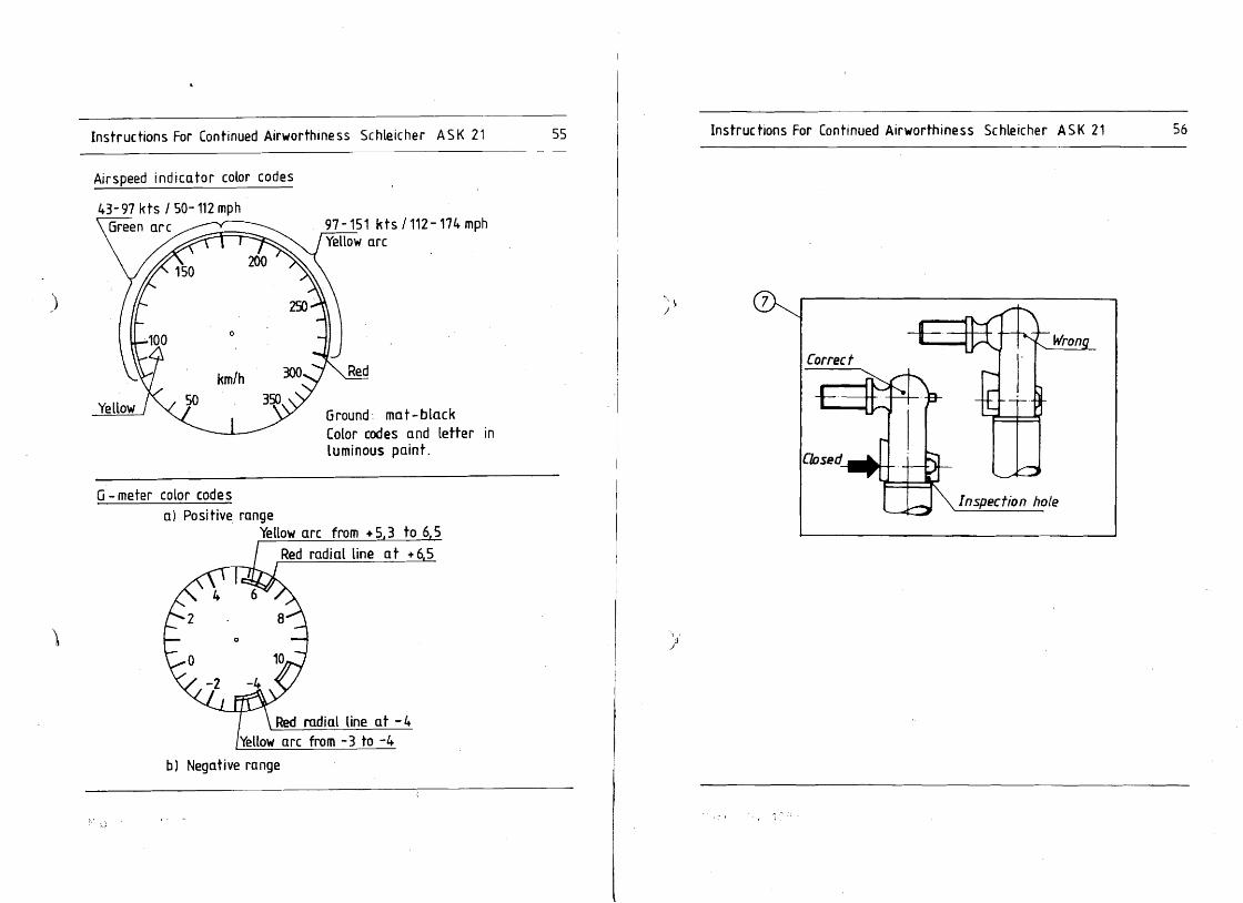
Data placard with weight &balance data; one placard each for the front and rear seat on the right cockpit wall. Fire-proof type plate; on the right at the spar tunnel bottom. Placard stating the approved Airworthiness Category; on the front instrument panel. Max. baggage compartment loading; one placard each left and right on the rear cockpit wall close to the baggage compartment opening. Placard on the rear instrument panel.' Placard for "Pre take off cheekY; on the underside of the front instrument panel cover so that the placard is visible when the canopy is open. Placard on left side of top of fin; Note: This placard is cancelled if your glider features the automatic elevator connection. Placard in the access hole cover ! Placard for tire pressure nose wheel: 2.. 0 bar. 'Placard for tire pressure main wheel: 2.. 7 bar. Airspeed indicator marking. G-meter marking.
Instructions For Continued Airworthiness Schleicher ASK 21 50
Setting of placards
'1 )
)'
December 20, 1983 TN no. 11 December 20 .. 1983 TN nO.11

Ins true tions For Continued Airworthine 55 Schleicher ASK 21 52 lnstruc tions For Continued Airworthine 55 Schleicher ASK 21 51
Setting of placardsFor tailwheel option only
X. PLACARDS AND MARKINGS
1. Data placard with weight & balance data; one placard each for the front and rear seat on the' right cockpit wall.
).> 2. Fire-proof type plate; on the right at the spar tunnel bottom.
3. Placard stating the 'approved Airworthiness Category; on the front instrument panel.
4. Max, baggage compartment loading; one placard each left and right on the rear cockpit wall close to the baggage compartment opening.
5. Placard on the rear instrument panel. 6. Placard for "Pre take off check";
on the underside of the front instrument panel cover so that the placard Is visible when the canopy is open,
7. Placard on left side of top of fin; Note: This placard Is cancelled if your glider features the automatic elevator connection . .Placard in the access hole cover !
8. Placard for tire pressure nose wheel: 2,,0 bar. 9. Placard for tire pressure main wheel: 2,,7 bar.
10. Airspeed indicator marking, )" ) 11. G-meter marking. 12. Placard for tire pressure tail wheel: 2,,5 bar.
December 20, 1983 TN no.11December 20" 1983 TN no. 11

Instructions For Continued Airworthiness Schleicher ASK 21 53 Instructions For Continued Airworthiness Schleicher ASK 21 S4
'\ I
)
Baggage in wingroots max. 2 x 10 kg Max. permissible 0(( - up weight kg
Loading of baggage compart
ment: max. 10 kg
Pre Take 0ff Check: 1. Controls easy to operate? 2. Airbrakes locked ? 3. Trim in the center position? 4. Parachute and safety harness
fastened? 5. Altimeter adjusted to field height
or to ;,ero ? 5. Radio "ON" and adjusted to
proper frequency? 1 Both canopies locked?
2 off
2 off
~ 1off
Segelflugzeugbau A. Schleicher Poppenhausen Model Serial no.
DA TA PLACARD Approved for: Max, speed for calm air Max, speed for rough air Max. maneuvering speed VM ,",ox. aero tow speed VF /oIox. winch launch speed Vw
WEIGHT AND BALANCE Min payload front seat Max. payload fran t sea t Max. payload rear sea t
28rf1iiirlfi 200 kmlh 180 km/h 180 km/h 150 km/h
I<g kg kg
~ 1off
Rear ,j
)
Attention! Emergency bailout! a) Pull bock both canopy side -locks and
canopy upwards. b) Undo safety harness.
c) Get up and bailout.
push
d) With manual chute seize release grip and
pull out entirely of ter 1 -3 sec.
rj) I r7iiiiJ:::i=r A. Sc hleicher~~ 6416 Fbppenhausen
Model: ASK 21
s.rial no: 21 XXX
Registra tion letters
Madem~stGermony
3 --'" Aerobatics prohibited!
1off Equipment as under airworthiness
category "U" (Utility)
>' 3 .-r Aerobatics as per Flight Manual
1off Equipment as under airworthiness
category "A" (Acrobatic)
'.,1
For equipment without
g-meter and bottom strap.
For epuipment with
9 - meter and bottom strap.
~ r; '.; ~
56
a) Positive range from + 5,3 to 6,5
radial line at + 6,5
'\ \ . }
b) Negative range
radial line at -4 from - 3 to -4
Red Yellow arc
Yellow arc
Red
lnstruc hans For Continued Airworthiness Sc hleicher ASK 21Instructions For Continued Airworthiness Schleicher ASK 21 55
Airspeed indicator color codes
)
Ground: mat-black Color codes and letter
"\ \ )
in luminous paint.
G- meter color code s Inspection hole
Correct

Instructions For Continued Airworthiness SCHLEICHER ASK 21 58Instructions For Continued Airworthiness SCHLEICHER ASK 21 57
XI. REPAIRS
)
On principle repairs ~ust only be made by the manufac
turer or by a certified (licensed) technical aviation
facility.
For excepticns see repair manual. In case of doubt con
tact the marufacturer !
XII. MODIFICATlm:s
Minor modification
A modification to the aircraft which has no influence
on its airworthiness and is feasable by using standard
working met~ods, may be done without prior notification
to the Civil Aviation Authority if it is done in accor
dance with a technical note issued by the Civil Aviation
Authority.
Major moditication
A modification to the aircraft which has an influence
)
on its airworthiness or requires a change of the opera
tion instructions or of the operation limitations or is
not feasable by using standard working methods, must on
ly be done by a certified (licensed) technical aviation
facility. The major modification must only be done in
accordance with technical documentations which were sub
ject of a supplementary type-approval under the test re
gulations for aircraft.
A supplementary type-approval is not necessary, if the
major modification is restricted to only some single
units. Prior to the carrying out of the major modification
the proof of the airworthiness must be furnished in ac
XIII. DESCRIPTION OF SYMBOLIC PLACARDS
IQDi)-1 Rudder pedals adjustment: grey
knob on RH side of the console.
\
">
To adjust pedals backwards:
Take your feet off the pedals and pUll pedals backwards;
then let go the grey knob and load the pedals in order
to lock them.
To adjust pedals forwards:
Pull grey knob and push pedals forwards with your heels;
then let go the grey knob and load the pedals in order
to lock them.
I oo~--L· I Airbrakes: blue lever in' the LH
~ arm rest; pull to extend airbrakes.
~ I Trim. noseheavy.
I ~ Trim: tailheavy.
I. ~ I Tow release: yellow knob LH below
~ canopy frame.-------I~J I~I
OPEN front canopy:
Hove white levers LH and RH on canopy frame backwards.
EMERGENCY JETTISONING of front canopy:
Push lever with red flat knob to the left
cordance with the test regulations for aircraft.
May 25,1984 TN no. 15March <:) 1983

60 Instructions For Continued Airworthiness Schleicher ASK 21Instructions For Continued Airworthiness SCHLEICHER ASK 21 59
I~I
) ~ Prior to toke off check the proper engagement 0 f the canopy locks! forward:locked
)
OPEN rear canopy and/or EMERGENCY JETTISONING: Move red levers LH and RH on canopy frame backwards.
Ventilation
This placard must be fitted in the front and rear cockpit in full view of the pilot.
TN Do.15May 25,198-'
XI V APPENDIX
XIV.1 Equipaent List
Minimum eguip-ent
1. Airspeed indicator
~ a. Winter GW 6005· 50 - 350 km/b b. PZL PS 08 50 -' 350 km/b
) 2. AlUm.ter
j a. Winter 4 BK 6 b. Winter 4 1GB 10 c. PZL V-12 Sh 3. Saret7 harne••
; \ Gadriqer Bap V-B/1
J Schugu II-C/V Bogu I-B/Y rront Bogu I-A/V rear
Additional minimum eguip.enttor aerobatics
G-meter BM 110 L
Additional minimum equip.ent tor cloud flying
Turn & bank indicator Apparatebau 8auting WZ-402/ 31. Compass: LUdolph FK 5
Ludolph FK 16 PZL as-1 PZL B-13/KJ
WF-transceiyer
a. Ditte1 "00 15/25 b. Ditte1 FOO 16/25 c. Di tte1 roo 40 S d. Becker AR 2008/25 e. Becker-AR 2009/25 t. Ayionic Ditte1 ATR 720
TN-No.20 dated October 16, 1987

__
Instructions For Continued Airworthiness Schleicher ASK 21
XIV.2 Maintenance Instructions
The following Maintenance Instructions are establishect from time to time as required, in accordance with experience accumulated in operating the ASK 21. The Maintenance Manual is to' be supplement~ ed in case of new issues of Maintenance Instructions.
The general "Maintenance Instruction All FRP GLIDER MODELS dated June 19, 1986" describes the removing of play between the sockets (= bushings) and bolts (= pins) of the wing-to-fuselage transition. .
) The • general Maintenance Instruction "PAINT CRACKS" dated June ~6, 1989, describes· h~w to inspect, preserve, and .repair the paint surface.
The Maintenance Instruction A for the ASK 21 (dated March 23, 1987) describes how to readjust the airbrakes.
The Maintenance Instruction B for the ASK 21 {dated July 4, 1990) describes how to install oversize drag pins (rear).
The Maintenance Instruction C for the ASK 21 (dated May 7, 1992) describes how to fix for the first time or how to replace the plastic fairing tape (elastic lipsea!) at the control sJ..Irface gaps.
)
TN24 dated 04.05.92 (Juw) 61 :..,,,
-.-------.. -- ..-~_ .. ...--.-r"~---- ..-.-.~- ....
Alexander Schleicher All FRP glider modelsSheet: Segelllugz.ugbouMaintenance Instruction1 of 6416 Poppenhousen dated 19.06.86
Removiny p.lay betw_~~.~ .. L~e sockets and bolts of the wing-fuselagetranSIt on
,. Longitudinal play between the four sockets in the wings and the bolts on the fuselage (Note: for the ASK 21. only ~he socket/bolt connection front in the wing nose/fuselage transition) leads to disturbing click-click noises when the rudder is operated, and can result in unpleasant tail oscillations at high speeds.
2. The play is fliminated by fitting metal washers of 022,5/32thickness according to the extent of the play. By testing.the play must be reduced such that the wings C4n be assembled still properly ~ this applies to a normal temperature of 20°C. Depending on the extent of the play. the metal washers can be fitted under one or more bolts.
3. The bolts are slid out of the fuselage cross tubes by fitting a steel rod through the hole in the opposite bolt. and drivingthe bolt out from the inside with a hammer (see sketch)below).
4. After fitting the metal washer(s). it should be po~sjble to drive the bolt back in .place. using only a 500 g ( ...., lib) hammer and a few blows. If it returns too easily. then knurl the seating area slightly until a tight fit is obtained again.
LJ '~. Pop pen hause n. J une 19 I 1986 ALEXANDER SCHLEICHER
GmbH & Co.
02/ -tJ ~~ Y:4:h L • -w. jlJ~~
~ 'i I~.", "."f" : 'I'I!'~ r;""'·Mt,...fl'uI'''· ft, fII fA' ~]

Alexander Schleicher K.intenance In.tructionSBEET: (,,"bl-t & Co,PAINT CIlCIS1 of 4 Segelf'lugzeugbau
0-6416 Poppenh.u.en
SHUT: K.int.napc. IUltructioD AJex"'" $c:hIefcher c::»mbH &. C",3 of 4 PAm CUCIS
S.gelflugz~gbau
0-6416 Poppenhau..n
Sub1ect: Paint crack. on fiber composite glider•.
Types ~,tlu~~~t; ASW ASK
12. ASW 15. ASW 17, ASW 19. ASV 20, ASK 21, ASW 22, 2J, ASV 24, A~H 25; ALL v.riant. and all serial no.s.
)
Compli anc~: 1. If deep crack. which go down to the fiber composite structure, .re found on the glider, the glider must be presented each ye.r to tbe a.~ufaeturer or any other licensed .,iation .t.tiOD, who upon examin.tion of the ~lider decide. whetb.r the glider c.n be continued in service for 1 year aoreorwbether the repair llIust be done at one. (see point "Action A.").
2. If hairliDecrack. which run only in the paint surface, .re found on the glider, the glider sh.ll be pre.ented at the l.test .fter three years .nnually to the manuf.cturer or .ny other licensed .viation station, who upon ex••in.tion of the glider Jecide. whether the glider can be continued in service for 1 year more or whether the repair must be done.t once (see point "Action D."). The 3 ye.rs extension applies only on the condition th.t the m.intenanee and care of the air craft is no longer, neglected during this period of ti_e and th.t the gliders .re no longer stored outside;
~-!.uon: Thp. Flight .nd M.inten.nce M.nu.ls for SCHLEICHER-gliders conta1n inlilt.nt notes conc.rning the detrim.ntal influence ot lIloisture .nd ,un r.diation on the aerodynamic p.int surf.ce quality ,t.nd.rd. Herewith we point out .mphatic.lly ORCe .gain th.t ev.ry owner is obliged to obs.rve the flight Ind m.intenance or operations manuals of hil glider in .11 points, .nd this referl allo to the relevant notes on the care .nd mainten.nce of the glider.
'\
/ It thele notes .re contr.vened, the result will be sooner or later - depending on the climate - da~age to the paint surface quality.
Influence of, the two f.ctors moisture and UV-r.di.tion~
To begin with, generally an enlArgeme~t of the waviness of the fini.h develop. - ••inly on the wing and tail unit skins - c.used by penetration of moisture. On the occasion of performance ae••urement. (accomplished by P.Bickle, R.Johnson .nd the Germ.n DrVLR/Idaflieg) it has been demonltrated repeatedly that the larger waviness leads alre.dy to considerable performance loss which is all distinctly noticed in competitions. A competition
1',.
O"E~ 1186
Action:
)
Torep.ir the p.int cr.ck., th••e h.ve to be r.moved g.nerdly by ,.ydb, thea dow8 to tbeir groupe!. But in 40i., 10, the, fib,r coapol1te••tructure Heing under the gelcOI.t .hQu14lSotbe sande. on. Thu. the ":1ding job is difficult Ind. therefore, rel.tively .xpenalv,.
A. It4eep cracuare concerned which go elown to or into tbetib.r co.~osite structure (it il aSlumed that they result froa l.rge .nd rapid temp.rature change. al found e.g. with wave flight.!), and ifa repair is decided to be nec••••ry, the p.int m.t.rial has to be ianded down~o tbe fiber co.po.ite .tructure carefully .nd the .re.effeete. mu.t be rep.ired. In c••e th.t tbe re.iD a.trix b••e of the fiber coapo.ite .tructure 1••lrt.dyd•••ged, one .hould conaider peeli~g oU Ind repl.cing the dam.ged fiber compoli t. layer . Thilf york 11 pOlli»ly e..ier th.n the c.reful unding job.
8. If h.irlin. cr.ek••re concern.d which run only in the palntsurfac. (and which pre.umably relult from bad mainten.nce togeth.r with continuous UV-radiationi.e. glid.rlleftoutsi4e without .ny protection for a long period of tim.), w. recO".nd to remove the paint m.teri.l froa .11 .re•• att.ck.~ by ••nding on them down their end and to rep.int the•• are••. The .ooner this a••aure i. t.ken, the l.s. the work expenditure.
On the .ubject of rebuilding tbe -p.int syatem with m.teri.l. .v.il.ble in the USA " w.ll •• on the .ubject of how to rebuil4' thi profile (wh1ch is • must for high'0
perform.nce g11der. Which' are to be flown in competition.) R.H.John.on, D.ll.. So.dng l ..ociation, h.. writ t.n ,..v.ral artich. publilhed il\ SOARING ••guin." We .dvi.e tocoD.ider in, .ny ~c.a' the r.p.ir .xperi.nce accuaul.t.d in, the USI., ro"r' Europe ...",gg.. t to .pray tb. saneled .u~:fac •• tint with polye.ter fillerl, loo ianeS" the••gain, .nd to respray the. " fin.lly thinly with • white paint .ystem on a Polyurethane b••i. which .bould b••ircraft-approved.
)
Material " drawinas: See above point ~Action".
Mass and e.G.: It 11 nec....ry to re4eteraine at terr.paintin'ga. After repa~ntingof control attention mu.t b. p.i4 to
th. •••• .nd e.G. data
.urfaces .nd fl.p. special their tailhe.vy b.lanc.
o\le.~ lU6
I

ASK ""11SHEET: AI.nnd.r Schl.icher , of 2 Maintenance Instruction A 0mlIH 'c•.
SegelllugZeUgbtu o· &4HI Po~nh.u ..n
•
£u.W.t
Affecting;
Complianc';
flw.2n.;
Jtjl' ~
Ul m UI II'ill
f1tt~ ,j' Material'
Poppenhausen. March
The translation into any case of doubt the
Re·adjusting the airbrakes.
Ali ASK 21 serial no•••
As required.
It is important to check in regular intervals the lock· ing of the airbrakel. Each airbrake has its own toggle in the wing. For this reason it mUlt be checked that both airbrakes lock simultaneously and securely.
1. This is checked by connecting the brakes individually and marking,thepolnt 0., the operating lever gate in the cockpit' at which tha linkage's dead center occurs. Both dead points should b' within 6 mm 10.2 in) of each other and, in the locked state, the individual brakes should still have 10 mm of free movement of the front l41ver forwards In the gate.
2. If you observe that the alrbrakes do not have an even over-center lock, the toggle over dead center must be readjust,d. Thi. must b. done with the alrbrake pushfod disconnected from the HOTElLIER ball Quick·disconnect. As shown in Fig. 1 the short pushrod (1) is to be disconnected from the toggle crank (2); back off the lock·nut 131 and .crew out the pushrod l'l"l by 1/2 to 1 turn. Re·connect In the reverse o,der and check again as d,scribed under point 1.1.
3. If the .irbrak.. Itill do not have sufficient dead lock force, peel a little off the toggle stop block (4). Using a punch carefully remove .ome layers from the stop t?lock (4): then again readjust the all" brakes as described under point. 1.1 and 2.1.
New safety nut NM 6. 'DIN 980-6. if needed.
23. 1987 ALEXANDER SCHLEICHER
GmbH & 00.
i 'J If) P, ~T1-h, ~1d L.W. Jumt .
English hIS been done by best k"owledge and judgement; in German original is controlling.
ovER. ..... 7t2
SHEET: Alexander Schleicher ';;'".,bH & (.r) ,
lSlU 1 of 1 Maintenlnce Instruction B Segelf'lugzewgbau
Issue I 0-6416 Poppenhau.en
Subject: Installation ot over.ize drag pins
AU'~t~llg.; All serial no .• ASI 21.
~Jio!H. '1. Derig the glider.
2~ To be able to safely reaa the new holes the safety clips have to be removed at the root ribs
"
J. Then rig the glider as usual and support the wings by use of wing .tands or equivalent (sav hor••• , trailerf·Jl dollies) ~uch th~t tbe drag pin. c.n be .•asily reAU' moved .nd in.erted.al
jif'" 4. Take ODe drag pin out, rea. the over.ize bole and in.ert new drag pin •{~•n
eJ } 5. Do the sa•• oD tbe otb.r .ide.
ti~ :~ 6. Derig the glider.
3d 7. Fix the safety clip. again at the new drag pins.Hi
;p ~ ~ ~ Note: Tbe following pin dia.eters are available:in 11.95 0, 12.0 Ill., 12.1 H, 12.2 mm and 12.3 .m. ~~N
tii,p1-' Poppenhausen, July 4, 1990 ·t E~H
rf~ ALBXAHDER SCHLEICHERttl
• t 1;0" i Gab~.C~in
~b.l. \, )
Tbe translation into English ha. been done by best knowledge and judgement: in any case of doubt tbe Geraan original is controlling.
1186

I
....v--.--.-__ .... ... _".._~ _~----~··I--.
-1L,5mm ...5.7 in.
cO·"..-.---~ -~~_.
:s ...... --:. ~------- __.:........:.._ ~---------.l.----'
·N

H 1 of 6
1 M.lnton.ne. Inatruetlon C
'"U. I
AI.llAnelllr Schlelch.r_.ca 1legoI~
o.&4lt"~
~ Fixing for the firat time at "placing the plestic fairing tape 'el..lie Iip..an ~VI' control lurface gapa. of aileron, and horizontal and vertical t.iI.
A1J.WIna; AII.ASK tl. O.ta Sh",t no, L·3311••• of ..rial no.21001, option.L
B.uw1; P.,torm.nce meuU,remente with v.rioua glidera h,ve shown that drag i:an oe con.idereoiy reduc,d oy a continuous trln.ition oetween wing and aileron 'and between lubUiztr and .Ievator r"pectively.
t,'j ~"
Thi' eontlnuou. trln.itlon ia achieved by meana of an elasticen lip..11 which la applied to the wing, the at.blllzer .nd the fin rllPKtlvely In ord.r to brldg. ,the .ctu.1 g'P oetween wino ,6 .iltron, .ttblllzer .. "'v. tor, 'nd tin" rudder, dueIii
~ICO ita curv.t'ur. IIIco which It II pre'formed to enaurl tight ..ating on the control .urfK". It is import.nt to ,nail,. th.t the 1••1 und.rnllth thil bridg· ing Iipalll II ~ 00 'l6 .'"Ight. Th. COntrol aurf.ce gapa .re ...Ied in .dditiOn by mlln. of • r.tlon a..llIIg/lHp tap., which .t the I.me time to reduce th'. friction of theih lIev.' el.stic Iipseal on the .iltron .nd .I.v.tor lurf.cea. Should the .llatic lip.eal come ott or 0' d.m.ged, thil may lead to lIutterltit"
II,I The .dditional .lleron, .......tor 6 rudder control friction gener.t.d la minim.I .nd .cc.pt.ble.hi,11'1 AWn; 1. If the el..tic 11'''111' WII not fitt.d b.fore to your
glider, a alllp rnu~ fir,t be rtOtt.d In the upper wing sur. face 81 IIluatrat.d In Pig. T, NOTE:d' Onlv the fllll.h laver " cer.fully remov.d down II far as the outer FRP lamination without damaging the gl..a laver.
Fig.1 lJ.Ril.lt Wing Surf.c.)
,"':........ _.
0\1 e:R... ","",t2
)~
Hl
lif' fll HI fli I"
HI )
SHEET: 3 of 6
ASK 21 . Malnt.nlne. In.tructlon· C
Illue I
Alex.nd., Schl.lcher CIrMM,'CD.
S9lllu;uUgCllu O·&4"P~_
Fig.3
Peel th' prot.ctive backing from the pilltic fairing strip 131 (Mylar foi!.30-15mm wid.) and firmly stick It on abutting the front ,dg. of the recessed step In· the wing by means of its adhesive film layIC IFig.31.
Now opply the .eal/ng/illp' tape 121 13M Scotch Teflon' T.pe 30 mm wide) 'ao"tting the reer edge of the temporary positioning t.pe t11. B. careful th.t the sealing/slip tape lies slack over the gap. Set .the aileron to maximum .pOllJiy, d.flectlon, so th't later the T,flon seallng/slip tap. ia not stretch.d during normalfull control deflectlonal Apply full .i1eron sevICal tim" 10 that the aeallng/slip tape fits w,lI Into th' gap. Then the T,flon sealing/illp tap. (21 must be firmly rubb'd down on to 'the luneee. .
Then remove the temporlry pOlltionlng tape (11 first applied,
Press the adhllive ZOn81 of th. plastic fairing Itrip flrmlv down on the surf.ca using • soft wooden block (e.g: Bslsal or a hard rubber rolllC.
Finally. a protli:tlv. adhesive t.pe (41 is sppli.d over the abutment of th.· front .dge of the pilitic fairing strip 131.nd the st.p In the wing [Fig.31. This t.p. should b. as thin and moisture-proof II possible; an example of a sult.ble tap. would ,be white Tesa film No,. 104, 25 mm wide. This protective tape SlrvlI to prevent the detachm.nt of the front .dg. of the p1l1tlc fairing Itrlp (el..tic lipsoan which might reau1t In d,ngerou. flight charect.rillics.
l.lll.Pl! Wing Surface
I'ftml.t2
:,~

There is no reces..d Slip at the stabilizer. As shown in Fig.42_ If th., .llItle IIp...1 ~ to be ',removed only for m.inthe sealing/slip tlpe 121 [3M Scotch Teflon Tape 30 mm wide]ten.ne. or repair purpo..., pi..... ob••rve the following: Is stuck on over the st.bilizer-to-elev.tor gap. At the s.me time the elevetor mu.t be .et to maximum positiye deflection,For df.....mbIV of elevator or ••eron: '.0 thlt I.llr the T.flon ...Iing/slip tlpe Is not .tretchedTh. ela.tlc IIp...1 and the .lIlIngt.lip tap. nlld to be during normal full control d.flectionsl remov.d gnIv on Jht upptr .udac. (where the control sur· Be c.reful thlt the ,...lIng/llip t,pe lies sl,ck over the gap,
·f.ce hlng.. .r. loeatedl. Apply full elevltor ..veral timel 10 th't the sealing/slip tlpe fit. well Into the glp.
For dl.....mbly of the rUdder: Then the Teflon "Iling/slip tlpe 121 mull be firmly rubbed H.re It i. .Qll1 n.c....ry to remove the elastic lipseal at down on ;0 the sudlce.the fin. '
2.1 Th. ..••tIc IIpI.II mu.t b. removed v.ry carefully so as . I}) F;g.• 'to .void any d.laminatlon. of the layer. in this ,r.a. Ae· ,. I ,
o'·mov,' ..ny .dhlllw-· residue by mean. of synthetic resin thin· t' .HI''''' ....< ri".. c
2.2' Aceompll.h Iny "(lquired In,jlICtlon, m.lnt.n.nc. or repair work It the control. .urfaee. th.matlv.. Ind t or their
., hinge•. IiIII H
"
fir 3. Bxlng for m. flrl1 tim. gr replacing the plastic fairina 'noe 'eilltlc Hp.lln, -I.. :' Not..:
- All .UdICII muat be completily cilln, dry .nd free from
.' du.t Ind gre..e' .. HI
J11 ,TN, can bI.t be t..t.d by stickinij a self adhesive t.p. '.. ,to, the cleaned ludl'ce .nd then pulling it off Iglin to ' check th.t no further du.t plrtlcl•• Idher. to It. fft
illCut the n.w .llItic pl..t1c fllrlng tlpe and the seeling/ The zig-zag-tepe (51 is .tuck on abutting the .dg. of thetil II'" t.p. into. IllIlfopri.t. length. (refer to the tlble unplastiC fairing .trip (31.)11 d.r point "M.terlal"l. NOTE: The' front teeth (in the direction of the flightl mustt,lfl ~ '" "f1 not be fllttened by prllslng them tOO f,r down into the glue
3.1 URIlil Wing Surf.ce film. otherwi.. their turbulltor effect will be reduced I tfl IApply I 12 moo wid.. IImporary positioning tepe 11) le.g: Fig.5 Horizont tall Wl.IlI! .udace
12 moo Ta.afilm 1041 abutting the front .dge of the approx. 17 min wide rec....d .tep (Fig. 21.
Fig.2 ~YVing Sudlce
,
"""T.12
,,",,7"
ASK 21SHEET: Maintenance Instruction C
Is.ue I 4 of 6
ASk 21Slit Alexander Schleicher Maintenance In.tNctlon C20f-8' _aeo. I••ue I ~
D·"'l"~ 3.2 Horizont tall Wl.IlI! .udece:
Peel the prot.ctiv. backing from the plastic f,iring strip (31 (Mylar foil, 30-150000 wideJ and, firmly .tlCk it on 10 the st,bllizer by m.an. of ItI Idhesiv. film 'I,yer (Flg.51. PreIS the adhesive zones of the pllStic f.irlng strip firmly down on the .uriace using a soft wooden block l•.p: Balsal or a hard rubb.r roll.r.
Alexlnder Schleicher GrrtbH&eo.
s.nugzougblu O·154'.P~

SHEET: ASK 21 Alexander Schleicher 5 of 8 Malntanlnc. In.tructlon C OIMHICo. StQeIfIuoZ"'ObIU'''ut' o.~te PoppenhIUMn
3.3 Wing and horizont tail ~ lurface:
Remove protective backing from plastic fairing strip 161 (Mylar foil 22·15 mm wide) and stiCk it on to the wing and horizontal tail ~ surfaces. by means of its adhesive film layer [Fig.61.
Prell the adhelive zonel of the pial tic fairing Itrip firm' Iy down on the surface Uling a soft .wooden block (e.g: Balsal. or a hard rubber rollerl
Then the. zig-zag-tape (5) il stuck on abutting the edge of the plastic f.lring Itrlp (e). lSe. the NOTE under
) point 3.21.
Wing and horizont tail ~ lurface!W SFlg.6
m fil,.11
HI III There are no recessed step. lit the fin. As shown in Fig.7>11
the plastic fairing Itrlp 16) (Mylar foil. 22·t5 mm widel
Til is stuck on over the rudder·fln transition at the left and right side (with its adhesive film layer on the fin!, thenj>.{ nrp,ssed firmly down on the surface.
~j
~ Then the zig'zag-tape (5) is stuck on abutting the edge of the plastic fairing strip.
-
3.4 Vertiealtail:
Fig.7
,"f'IIl7 ''2

SHEET: 6 of 6
ASK 21 Maintenance Instruction C
Illue I
Alexander Schleicher om~'Co
s.ftuGzl\lOblU 0·8418 PoppenI\Iusen
MJ1I!iil.i.
OptIonal in the place of (51 and Ie):
Wil\9 '1£1' Horizontal Vel,"t1.cal face. Tail Sfe•.• Tail Sfe•. e
'>
jf'I t
m
• • left and righttil The materials reQuired can be obtained from Messrs. Schleicher,
1:1 ~ , " This action can be accomplished by a competent person.
2. ,In the place of the plastic faifing tape (61 and the zig1It1
1' '~Z8g·tape IS) optionally a combi·Zig·zaglplastic fairing tape (7) may be glued on,
1ft 3, Ensure that the .taltic Iip,eal is in tight contact with the surfaces of the controls even when they are 'fullyIp deflected.
>11The secure and firm adhesion of the elastic lip must be ehecked.'ft
Poppenhausen, May 7. , 992 ALEXANDER SCHLEICHER
G,mbH & CO'~, ·n ,,J.-. / / ,_~~"I-It! -. .' . (Lutz-W.Jumtow)
The translation into EngliSh hall been done' by best knowledge and judgement: in any case of doubt tho German origi"~l is controlling.
"'''' ,.,

Airworthiness Luftfahrt-Bundesamt Airworthiness Directive Seclion Directive Lillenthalplatz 6
1993·001/3 38108 Braunschweig .Ii Federal Republic of Germany
L'Hotelller ball and socket connectors IEffective Date: April 09, 19981
Affected; Kind of aeronautical product: Manufacturer: Type: Models affected: Serial numbers affected: German Type Certificate No ..
Aircraft L'Hotellier L'Hotellier ball and socket connectors with lock plates ball and socket connectors with lock plates all none
Subject: l'Hotelller ball and socket connectors with lock plates if installed in sailplanes, powered sailplanes and aeroplanes
B.!!!2D..i. Reported Incidents involving L'Hotellier ball and socket connectors have prompted the lBA to have investigations made as to the operational safety of l'Hotellier ball and socket connectors.
The results have shown that the friction surfaces of the lock plates will be run in and smoothened after a relatively smaU number .>f operations. As has been demonstrated in the tests, in this case even normal operating conditions are sufficient under unfavourable circumstances to surmount the static friction (i.e. the lock plates open). The a.m. airworthiness deficiency may result in inadvertent disconnect of the l'Hotellier ball and socket connectors and thus to considerable operational malfunctions.
U1 o Controllability of the alrcran may be affected or even lost so that the defect may lead to an accident. to The reason for the .Issue of the second edition in April 1994 was the revision of the L'Hotellier Instruction for Main
tenanct' by which the roundness tolerance of the ball was increased from max. 0.05 mm to 0.1 mm. The ball and socket connectors are to be secured by means of safety pins, Uer1ings sleeves or Uerlings type sleeves
This AD has been Issued as a result of several occurrences with Uer1ings type sleeves. For well-founded reasons, especially these sleeves are to be inspected for absense of cracks and sufficient self-locking ability and, if necessary, are to be replaced.
Action; The Lunfahrt-Bundesamt emphaclzes the fact that all pilots have to familiarize themselves with the particularities of l'Hoteliler connectors, especially with the different locking systems and their handling The ball and socket connectors with lock plates are to be secured. For this pUflJose. the following ac1ions are to be accomplished:
1. Safety pins (e.g. l'H 140-31 made by Hotellier), have to be retrofitted, if not yet installed. In certain cases, it may become necessary to rebore the hole in the lock plate, whiCh is provided for visual inspection. to 0 1.2 mm so that the safety pin can be Inserted (see attachment section I).
The use of a' safety pin can be waived if the L'Hoteilier ball and socket connedor is already equipped with an approved locking system (e.g. Uer1ings type sleeve, lS locking sleeve, Schempp-Hirth spring or Wedekind locking system) or if such a system is to be installed.
L8A approved locking systems: see attachment section II. Uer1lngs type sleeves (specification number SE-001(78) as well as lS iockmg sleeves can only be used for straight Joints and transmissions, but cannot be used for 90° joints.
Inspection of Uerlings Type Sleeves
~ Airworthiness Luftfahrt·Bundesamt Directive Airworthiness Directive Section
Lilienthalplatz 6 . 1993-001/3 38108 Braunschweig
Federal RepUblic of Germany .,.~
Inspection of these sleeves for the absence <Jf cracks and sufficient locking force (self-locking ability), replacement of the sleeves, if necessary (see attachment part III),
Installation information: The sleeves have to be slid axially onto the l'Hoteliler ball and socket connector, they may by no means be clipped radially onto the l'Hotellier ball and socket connector. Radial clipping (excessive opening of the sleeve) may lead to cracks or ruptures due to overstressing so that the sleeve cannot function properly any more.
Annual inspection of sleeves: The sleeves shall be inspected at least once a year for the absence of cracks and sufficient locking force (selfI, -Idng ability). In the original. specification for the Uertlngs sleeves a biannual replacement interval Is assumed.
,lations from this provision are stated in the technical information by the manufacturers.
2. Flight Manual a) Section "Rigging"
The recommendation: "The lock plate of l'Hotellier ball and socket connectors should be secured·... given in several Flight Manuals in the a.m, or in a simular form is to be deleted and to be replaced by the following sentence:
'ihe l'Hotelller ball and socket connector must be secured,"
b) If older Flight Manuals do not contain information about l'Hotellier ball and socket connectors, section IV (see attachment) is to be included in the Flight Manual under the Section "Rigging", If the l'Hotellier connector Is or is to be secured by means of a safety pin. If necessary, the entry is to be Included on a new page.
c) If Uer1lngs type sleeves are used as additional locking systems for l'Hotellier connectors, section III of the attachment is to be included in the Flight Manual.
These entries in the Flight Manual may be hand-written or inserted as a copy indicating the AD-No. 1993-001/3 in the Flight Manual.
The amendment is to be entered in the list of effective pages indicating the AD-No. 1993·001/3,
3. Maintenance Manual The enclosed Instructions for Maintenance (l'Hotellier, issue E 03/94) become herewith part of the operating instructions and are to be included in the aircraft Maintenance Manual - as far as this has not been done already by the manufacturers of the sailplanes, powered sailplanes, and aeroplanes concemed.
4. AlIl'Hotellier ball and socket connectors are to be Inspected In accoroance with the above Instructions for Maintenance.
\:nectors exceeding the allowable tolerances are to be replaced.)
Nore: Type-related technical Information already published by the manufacturer or by the product support organisation for L Hotellier ball and socket connectors become part of this AD.
The safety pins are available from: - l'Hotellier safety pin, reference no. l'H 140-31 - safety pin 01.2 mm, Foro reference no. 1473 931 (wor1dwide) - manufacturers or product support organisations for the sailplane, powered sailplane or aeroplane typesconcemed
Compliance: locking of L'Hotelller connectors: • on sailplanes and powered sailplanes not later than April 30th
, 1994. • on aeroplanes not later than May 15th
, 1998,
Inspedion of the Uerlings type sleeves on all aircraft:
Enquiries regarding thl!! Alrworthlnen Directive should be referred to MIOlaf Schneider, Airworthiness Directive Section at ttle .bove address EnqUiries regarding this Alrworthlneu Directive !!hould be relerred \0 Mr.Olar SChneider, Alrworthlnen Directive Section at the above addre!!!!,
lax-oo. 0049 53112355-254. Pleue note, that in cne or any dllflculty, reference should be made to the German issue I fax-no. 0049 53112355-254. Plene nole, that In cne 01 any dllllcu!ty, relerence !!hould be made to the German Inuel

...>-"" Airworthiness Luftfahrt-Bundesamt Airworthiness Directive Section Directive Lilienthalplatz 6
1993-001/3 38108 Braunschweig#l£1A Federal Republic of Germany Attachment to Airworthiness Directive No. 1993-001/3
With the next annual Inspection but not later than May 15th , 1998, and thereafter at least once a year. L'Hotellier ball and socket connector, lock plate
Attachment page 1 of 4 TectlOical publication by the manufacturer: ·none·
U1 ....... o
,f
Accomplishment and log book entry; Action to be accomplished byan approved maintenance organisation and to be checked and entered in the log book by a licensed inspector.
Note; This AD supersedes the AD·No. 1993-001/2 dated April 20,1994
Holders of affected aircraft reaistered in Germany have to observe the following; As a result of the a.m. deficiencies, the airworthiness of the aircraft is affected to such an extent that after the expiry of the a.m. dates the aircraft may be operated only after proper accomplishment of the prescribed actions. In the interest of avIation safety outweighing the Interest of the receiver in a postponement of the prescribed actions, the immediate compliance with this AD Is to be directed
Instructions about Available Legal Remedies; An appeal to this notice may be raised within a period of nne month following notification. Appeals must be submitted in writing or registered at the luftfahrt-Bundesamt, lilienthalplatz 6, 38108 Braunschweig.
Section I
L 'Hotellier ball and socket connectors with lock plate
"If the connectors are not yet equipped with safety pins (e.g. I'H 140-31 made by Hotellier), these safety pins have to be retrofitted. In certain cases it may become necessary to rebore the hole in the lock plate, which is provided for visual inspection, to 0 1.2 mm so that the safety pin can be inserted.
lock platesocket hole
ball
Warningl Un,ecure~ball and socket conneetocs may open automatically in flight! _
I'Hotellier connector
\ 1. .)
Enquiries regarding this Airworthiness Directive should be referred to Mr.Olsf Schneider, Airworthiness Directive Section at the above address. fex-no, 0049 531/2355-254. PI...e note, thst In case of sny dlfrlcully. reference should be made to the German Issue I
I

Attachment to Airworthiness Directive No. 1993-001/3 L'Hotellier ball and socket connector, lock plate
Attachment page 2 of 4
Section II
LBA-approved locking systems
The following systems to secure I'Hotellier ball and socket connectors are LBA-approved: Uerlings sleeves or Uerlings type sleeves (see section III), safety pin (figures 2 and 2a), LSsafety sleeve (figure 3), Schempp-Hirth spring (figure 4) und Wedekind locking system (figure 5).
fig.2a
U'1 -0. -0.
fig. 3
I~
~---f--t fig. 4
I I I I
i
____....JI
Attachment to Airworthiness Directive No. 1993-001/3 L'Hotellier ball and socket connector, lock plate
Attachment page 3 of 4
Section III
Installation instruction for Verl/ngs type sleeves
For installation, the sleeves have to be slid axially onto the "Hotellier ball and socket connectors.
They may by no means be clipped radially onto the I'Hotellier ball and socket connector. Radial 'iC?ping (excessive opening of the sleeve) may lead to cracks or ruptures due to overstressing so
',t the sleeve cannot function properly any more.
Installation ~ .l of sleeves --~-_.- ., ~1-:3m-
connection of controls
locked
locked and secured
i I '------- !

Attachment to Airworthiness Directive No. 1993-001/3 L'Hotellier ball and socket connector, lock plate
Attachment page 2 of 4
Section II
LBA-approved locking systems
The following systems to secure I'Hotellier ball and socket connectors are LBA-approved: Uerfings sleeves or Uerfings type sleeves (see section III), safety pin (figures 2 and 2a), LSsafety sleeve (figure 3), Schempp-Hirth spring (figure 4) und Wedekind locking system (figure 5).
U1 -" -"
fig.2a
fig. 3
{~
~---E---t fig. 4
I I I I
i I__...J
Attachment to Airworthiness Directive No. 1993-001/3 L'Hotellier ball and socket connector, lock plate
Attachment page 3 of 4
Section III
Installation instruction for Verl/ngs type sleeves
For installation, the sleeves have to be slid axially onto the "Hotellier ball and socket connectors.
They may by no means be clipped radially onto the I'Hotellier ball and socket connector. Radial ';C?ping (excessive opening of the sleeve) may lead to cracks or ruptures due to overstressing so
',t the sleeve cannot function properly any more.
Installation ~ ~ of sleeves --1==j---- If -fEt-~
connection or controls
locked
locked and secured
i iL..-____ !

Attachment to Airworthiness Directive No. 1993-001/3 L'Hotellier ball and socket connector, lock plate
~ttachment page 4 of 4
U1
t\)
Section IV L "Hotellier ball and socket connectors
Prior to the installation of ball and socket connectors, ~veryone has to familiarize himself with their functioning. .
The socket is to be slid completely over the ball with the lock plate pressed down. During locking the lock plate moves back slightly so that in a correct connection the hole on the narrow edge of the lock plate becomes visible.
The safety pin is to be inserted in this hole thus securing the ball and socket connector,
Attention: By loading the connection full engagement of the ball is to be verified!
lock plate socket hole
"Hotellier connector ball
Warning! Unsecured ball and socket connectors may open automatically in flight.
DOCUHEUT Ito. N° : 10.01 INSTRUCTIOllS :FOR THE MAINTENANCE E08·A
L'HOTELLIER BALL AND SWIVEt JOINTS
DOCUMENT I%iA Ne : 10.01 LTA-Nr.: 93"OOA /''Rev: !
E08·A
CO~OSITION DU DOCUHE~r
PAGE IND. PAGE IND. PAOE IND. PAGE IND. PAOE IND.
TIT E SOH E 1 E 2 E
) I;UHMAJI.Y
l - PREVENTIVJ: AND SAnTY MAINTENANCE UfSTRUCTIOUS
2 - PERIODICAL CHECK
2.1. FREE MOVEMENT OF THE BALL INTO THE UOUSINO 2.2. BALL SPHERICITY MEASUREMENT (8•• fig. 2) 2.3. BALL THREAD CHECK 2 ••• SWIVEL VISUAL CBEC~
~.5. MEASORE~~NT OF THE LOCKER LOWER PART PROJECTION AFTER ASSEMBLY or THE. BWIVEL ON TIE BALL (S •• fig. 1)
2.6. CHECK THE LINK BrrwEEK DRIVE ROD AND SWIVEL 2.7. ~WIVEL ASSY'OPERATIOH CHECK
)
RED.:OB DAT1i:;~.· PAGE: SOM IND.:E _ ,
-, I
INSTRUCTIONS FOR THE MAINTENANCE . ."
L'liOTELLIER BALL AND SWIVEL JOiNTS
) '"
IU~IUQUI: DU DOc:uxBHT
U:V. ' DATI OBJET DE LA HISE A JOUR REO. QU,AL. RESP.
AI C D
0
1
11/85 02/86 01/89 0'7/92 03/94
Cr.ation of document' R.pr•••ntation of 1 .wivel Adjunction of Fig.l and Fig.2 U~atin9 of function of CR147, Updating following DEI229-EH
BE BE BE BE
B~
HJD HJD HJD· HJD HJ~
JHB JHB JHB
JHB ~~ J/1!:.j. ,
, Lun .DBI DES~IHA1'AI1lt8 '
••••a.e. a·C.
1.0• ' I.e.
C.I.
OR. +1 IX. 1 EX. 1 EX.
'RODUCTION 1 IX.
RliD.:BE DATE: 03/94Louis L'II~1ER 5.04, PAqE.: TIT IND. :E9). ,venue Oatla De OIUU•• 92270 OOIS COLOMBES
T~I.(1)42.42013.94 T~I&lIo 6111S3F lJ{9TAIR Telkopie (1)47.60.07.07'

DOi:ti71EHT II~\
N° : ':'u.Ol UI8T'1UCTIOUS FOR 't'31:: HAlllTENANCE ::08·A L' HOT]~LLIER BALL :UTD S~IVEL JOINTS
"
DOCUMENT I~
N° : .10.01 INSTRUCTIONS .z·OR THE KAINTEH~'lCE
L'HOTELLIER BALL 1~D SW~VEL JOINTS E08·A
1 - I'RE'GHTIYJ MP !JAn" &IHTtNIUIC; IlfsInvc;lous
Th. rot.tion,of the' .wivel a~ound th. b.ll Iftuat b. done with r •• iating .trengh, due to minimum friction •. con••qu.ntlY,it ia m~nd.tory to.lubr~c.t. the .wiv.l/b.ll •••y. Thi. lub~ific.tion muat'b. don••tt.r cl••ning .nd b.for. ••••mbly,with •. non cold coagulating gr..... '
Ig I ZSSO purpo•• (9.~.r.l u.S) I
Spr.y cont.ining oil••nrich.d w!th .ilicon. (r.comm.nd.d for ,••••mbli•• • xpo••d to ••nd or oth.r .br•• ive m.t.ri.l~).
It i. m.ndatory to ~.rify, .ft.r ••ch ••••mbly, the corr.ct loc.tion of the ball in the .wiv.l. To do .0, • loc.tio'nhol. i. drilled in the lock.r. Wh.n the ) al ••mbly i. good, the hal. mu.t b. vi.ibl••nd mu.t .n.bl. to in••~t th.·pin "S" r6f. L'H 140-31, or oth.r d.vic•• , linked to the lock.r only.
2 - PERIODICAL CIEC5
During the .nnu.l Yi'i~ or no lat~r than .v.ry ~OO fligbt hour., i~ i. n.c••••ry to verify ball••nd Iwivel••• follow. I
2.1. TREK MOVEMEH: or TRE BALL I~O 1'B~ ROUSING
- Check th.t the b.ll move fr•• of friction point. Ch.ck the .ngul.r di.pl.c.m.nt.
- Ch.ck th.t th.re i. no cr.ck .t the b••• of the b.ll
2.2. BALL I'IZRICIZY HEA'~HT (~•• tig. 2)
Th. v.ri.tion b.tw••n ••v.r.l m••,ur•• of the ball diamet.r mu.t not .xc••d 0,1 mm. Thia check .im i. to d.t.ct .n .bnorm.l b.ll w••r.
2.3. BALL TRRZAD CBZCX
H~ thr••d damag. i ••cc.pt.bl•. During r •••••mbly the collar mu.t b. p.rf.ctly ••~ on it. b•••. It i. mandatory to fix the ball in poaition'with ).n .d.quat. locking d.vic•.
2••• SWIVEL VISUAL' a,ECK
NO deformation or p~~ning in ball location or in the locking device ••at ia .cc.ptabl••
2.5. MEAsUREKENr Dr TDE LOC~R LOWER PART PROJECTION AFrER ASSEMBLY or TBm SWIVEL'ON THE BALL ( ••• fig. 1)
I.Thi. 'proj.ction mu.t b. higher than 2 mm•. Th•• im of thi. r.quirem.nt i. to verity ~h. etticiency ot the .utom.tic t.k. up cl••ranc.
2.6. CHEC~ OF TUE
In the ca.e ot an 8wiv~1 and drive locking device.
2.7. SWIVEL ASSY
LINK BETWEEN nRIVE ROD ~lD SWIVEL
adju8table swivel, verity th.t the link betw••n rod i. tight and properly .ecured by .n ad.quate
OPERATION CHEC~
Seat or lock.r I no clamping, due ~o oxyd.tion or oth.r r •••on, i • accept.bl••
't.tter th••• verific.tion., on. of the above ch.ck i. out ot tol.rance, it i. m.ndatory to replace both b.ll .nd '.wiv.l. n.verthel••• it i. recommended to r.pl.ce this a••embly .vety 10 y.ar. or .v.ry 3000 flight hour••
IMPORTANI' NOTE
Any de!e~tion p.rt. may be ~eturn8d to Et. Loui. L'~OTELLIER for technic.l inve.tiqation.
FIG. 1
dALL '" S'NIVEl JOINT:i ! ""
PLATE HOLE
"
) FlO.
"
...
.:;;t
IA_8I<O,1 )Oft'"
. ! I'
, RED.: BE DATE ~ O~/94 1Lou~ L'1I0TELLIER 5.04. PAGE: 2 IN?,; E ,93. IIvenue Cb.rles Dc Gllulle· 92270 BOIS COLOMBES
T.;I.(I)42,411J 94 Tc!IeJ 61' IBF I.HOTAJR Tt!I~nie (1)47.60.07,07.. r.••1""'..y.,......'" fN"f'~.nrr, .~","""\.ft"'1 ............I .. ~~
Louis L'HOTELLlER 5.04. RED.:BE DATIi :'03/94 9-3. Iyen... Cbllr'-' D. Oautl.· 92270 BOIS COLO~BES PAOE :,1' IND. :8 nl.(1~.42.13.94,T"c1611153P LHOTAIR Tllknpio (1)47.60107.07

Bad wedging effect causing wear of the ball. "'" .
~
;';- (,,";"
J"" .... ~:r i' .... ." '"'" l' . 1~/.::-'" •..... 1. A ~ K .c:;, MaJ.ntenance Manua
-,;2.·~ . ",' 'As ~~ accumulated in AuStralia. bas~, 'the CCIlditicn of , the .Il~ connectors must be checkedal every .annual
~tiOh 'pf the aircraft, especially when it bas ~ opE!l'ated'f' . tl and fran """,,"P airfields. .' . . .~:. requen ,y .~.l . .
,.,.
•
Itf'
j' •
\ \.... ...
\'1'.
\'
r--..;.;;;.....;.;;;...__-.,.._.,..--~C1~earan~.. ~ce~'-:.,.;A2:· must riot . exceed 0,15 !lID'"
(0,006 in): check this by using a wire of the ab:>ve diameter!
i
. !
I...
. ball ends are 1:ikely to ~ under beM~ inq loads in the thread area.;.· Gap generated .bY an ~ and~
>--J::zI P', ,~;-. -,--r';';;ec~tl~y refitted ball end or owing to'overloading lwear· out of the lever part.
.~
. 'lhe greatest and smallest diameters B to be foond ,JDUSt 1'lQS,~piffer 111 .•~ tbal)"~l.(9,Q04~~.~: , .
I t:¢wwiwuw? J; '[ ,"
'h._..~~' 't
/"<"""0,., ,,;p~:t'~$~':,. 'lhe tight _t" of the bW: ~.iil8ide the fittings must be cheCked as loose
I f"(.\ ---, :'~
'\
"h:~l j J .'\ j,
.. "' >i...
...
\ \
. (
i