instrumentation limited (summer training report), kota
TRANSCRIPT

1
INDUSTRIAL TRAINING REPORT ON
INSTRUMENTATION LIMITED, KOTA
(In Partial Fulfilments of the requirement of the Degree)
Guided By: Submitted By:
Mr. A.P. PADRAHA RAM SWAROOP KUSHWAH
(AGM, Training & Development) (121769)
Submitted to
DEPARTMENT OF MECHANICAL ENGINEERING
JAYPEE UNIVERSITY OF ENGINEERING & TECHNOLOGY
GUNA, (M.P.)

2
CERTIFICATE
This is to certify that RAM SWAROOP KUSHWAH (121769) student of
Mechanical Engineering Department, Jaypee University of Engineering and Technology,
Guna has completed the industrial training at INSTRUMENTATION LIMITED, KOTA for 6
weeks for the partial fulfilment of the requirement for the award of Bachelors of Technology
(Mechanical Engineering) degree of JUET, Guna.
This is a record of student’s own study carried under my supervision and guidance. It
is further certified that candidate has worked under supervision required under the industrial
rules.
Mr C.P. Verma Mr A.P. Padarha
(General Manager, T & SD) (AGM, HRD)

3
PREFACE
To expose the student to the industrial environment.
To provide an opportunity to observe the processes, procedures and standards that the
industry uses to ensure quality, productivity and economy of the products or services that is
undertakes.
The major objective of training is to make students familiar with the organization culture and
practical work environment. Moreover it also provides in- depth knowledge of the topic
assigned.
Project Report enable the student to undertake a theoretical project in order to study, interpret
and report on one or more management problems and situation. To relate the knowledge with
the industrial experience.
My Summer training at Instrumentation Limited, Kota was a memorable experience as it
allowed me to learn a lot of things in a programmatic manner.
Ram Swaroop Kushwah

4
ACKNOWLEDGEMENT
It has been made possible through the direct and indirect co-operation of various
persons to whom I wish to express my appreciation.
I express my deep gratitude to Mr. A. P. PADARHA (AGM, HRD) who provided me
an insight into the working that enhanced my knowledge and with their support and co-
operation this report has taken a presentable form. I am gratified to Mr. C.P. VERMA
(DGM,T&D) who guided me and provided the opportunity to get acquainted with the
organization culture and also supported to know the various operations of the organization.
I take this opportunity to express my profound gratitude and deep regards to Mr A.P.
Padarha for his exemplary guidance, monitoring and constant encouragement throughout the
course of this training. The blessing, help and guidance given by him time to time shall carry
me a long way in the journey of life on which I am about to embark.
I would also like to thank the training in charge of Jaypee University Of Engineering
And Technology, Guna, M.P. and all the faculty members of Mechanical Engineering
Department for their effort of constant co- operation, which have been a significant factor in
the accomplishment of my industrial training.
This dissertation will not be complete and I to will be failing in my work if I do not
work place in the record my gratitude to our sir who in their respective capacities as lecturer
guide in my work. he gave me invaluable suggestion and timely advice.
`` RAM SWAROOP KUSHWAH
(121769)

5
CONTENTS
PAGE NO.
CERTIFICATE I
PREFACE II
ACKNOWLEDGEMENT III
CHAPTER 1: INTRODUCTION TO INSTRUMENTATION LIMITED 1-16
1.1 Introduction 1
1.2 Organizational Structure 2
1.3 Kota Unit 3
1.4 Product from Kota Unit 4
1.5 Product from Phalghat Unit 4
1.6 Departments in Kota unit 5
1.7 Present status 6
1.8 Important Milestones Achieved 6
1.9 Some other awards 7
1.10 I. L. infrastructure 7
1.11 Costumers of IL
CHAPTER 2: SAFETY MANAGEMENT 8-9
2.1 Introduction 8
2.2 Employee Responsibilities 8
2.3 Personal protective Equipment 9
CHAPTER 3: Quality and Assurance 10-11
3.1 Introduction 10
3.2 Quality Control System 11
3.3 Dimensions of Quality 11
CHAPTER 4: PREPARATORY SHOP 12-15
4.1 Introduction 12
4.2 Shearing 12
4.3 Bending 13
4.4 Notching 14
CHAPTER 5: FABRICATION SHOP 16-20

6
5.1 Introduction 16
5.2 Arc welding Process 17
5.3 Gas Welding Process 18
5.4 Resistance Welding Process 19
5.5 Resistance Seam Welding 19
5.6 Welding Defects & Preventations 20
CHAPTER 6: CNC MACHINNG CENTRE 21-23
6.1 Introduction 21
6.2 CNC Lathe Centre 21
6.3 Features of CNC 22
6.4 Absolute System 22
6.5 Part Programming 23
6.6 CNC Milling Machine 24
6.6 G-Code & M-Code 24
CHAPTER 7: Conclusions 25
References 26
Appendix 27-31

7
LIST OF FIGURES
FIGURE
NO.
FIGURE NAME
PAGE NO.
1.1
1.2
1.3
Organizational structure
Kota Unit
IL department
2
3
5
2 Safety Equipments 8
4.1
4.2
4.3
4.4
CNC Shearing Machine
Bending Operation
Geometry of Bending Allowance
Copy Press Punch Operation
12
13
13
15
5.1
5.2
5.3
Arc Welding Set up
MIG set up
Electrode Wire Seam Welding Process
17
18
19
6.1
6.2
CNC Lathe Machine
CNC Milling Machine
23
24

8
Chapter 1
INTRODUCTION TO INSTRUMENTATION LIMITED
1.1 INTRODUCTION
The Instrumentation Limited a Govt. of India Enterprises was set up at Kota in April 1964 in
collaboration with Russia with a provision to set up second unit at Palghat in Kerala. The
production was started in October 1968. It holds good rank in India in the field of Process
control instruments. Whatever the capacity of field may be one can only rely on IL board
based engineering capability expertise for instruments for requirements. Whatever the
capacity of the control system required whether in computer electronics or pneumatic field.
I.L. is supplying the said system on turnkey basis.
Kota office basically a co- ordination office which is to co-ordinate between marketing
head quarter branch office and various departments at Kota for timely execution of order and
complete customer satisfaction. Kota office is also responsible for booking of orders for all
telecom products. I.L. specializing in the turnkey Process Control Instrumentation to record,
monitor and control process parameters in process industries. Instrumentation Ltd. Takes
total responsibility for engineering, manufacturing, erection and commissioning of
instruments with a backup of sales services.
Just from the first year of production the company has been successfully supplying
instrumentation and control equipment’s and has achieved all time high record of production,
turn over in profit. It has continued to play its vital role in speedy development of process
industries throughout the countries in such a brief period and the company has achieved a
leading, reputable and important position not only in India but in abroad also. In recent past,
the company had entered into technical collaboration with M/s Hartmann and Braun., West
Germany in March 1986, for manufacturing of gas analyser the production of which was
started in Dec 1986.
This production unit was set up in collaboration with M/s Premmash Export USSR. This
plant commenced its sophisticated process control instruments in various ranges. The Kota
plant cater the need of industrial Process Control Instruments required by various thermal
power stations, electricity boards, Steel and Chemical plants, Chemical industries, Paper
industries and and other heavy engineering units.
Kota office basically a co- ordination office which is to co-ordinate between marketing
head quarter, branch office and various departments at Kota for timely execution of order and
complete customer satisfaction. Kota office is also responsible for booking of orders for all
telecom products. The purpose of setting up of IL was to attain self-reliance in C&I field for
process industries. After contributing its share towards this objective it was thought proper to
utilize the expertise gained in field of high tech electronics and manufacturing facilities in
other areas. It was decided to use the expertise gained to help Defence forces in getting the
equipment Indigenously. Keeping this in view a separate group was formed to liaison with
agencies like MOD, Ordnance factories etc to find out the requirement which IL can design,

9
develop, manufacture and supply meeting the stringent Defence specifications. IL has till
now developed and supplied following items to Defence establishments.
1.2 ORGANIZATIONAL STRUCTURE
Once the decision has been made to begin a retail venture, it is necessary to plan its
organizational structure in a way that maximizes efficiency and profitability. All of the duties
and responsibilities of those in the company must be identified, and lines of authority must be
carefully delineated so that all members of the organization will understand what their job
responsibilities are. By doing so, everyone knows who will report to whom, who the
decisionmakers are, and which advisory personnel is on hand to assist in the decision-making
process. IL lays great emphasis on documentation from start to finish. , it is necessary to plan
its organizational structure in a way that maximizes efficiency.
Fig.1.1 Organizational Structure in IL

10
1.2 KOTA UNIT
This plant is located at Kota-Jhalawar road kota-5 (Rajasthan). It is the berth place of
Instrumentation Ltd. This production unit was set up in collaboration with M/s Premmash
Export USSR. This plant commenced its sophisticated process control instruments in various
ranges. The Kota plant cater the need of industrial process control instruments required by
various Thermal Power Stations, Electricity Boards, Steel and chemical plants, chemical
industries, paper industries and other heavy engineering units.
Fig. 1.2 KOTA UNIT (Ref-IL)
Just from the first year of production the company has been successfully supplying
instrumentation and control equipment’s and has achieved all time high record of production,
turn over in profit. It has continued to play its vital role in speedy development of process
industries throughout the countries in such a brief period and the company has achieved a
leading, reputable and important position not only in India but in abroad also. In recent past,
the company had entered into technical collaboration with M/s Hartmann and Braun., West
Germany in March 1986, for manufacturing of gas analyser the production of which was
started in Dec 1986.
1.3 PRODUCT FROM KOTA UNIT
This is the oldest unit. Main products from this are:
1. Annunciators
2. Gas Analyser & Pollution Monitoring Instruments
3. Microprocessor Based Controller and Recorder
4. Electronics Transmitter
5. Pneumatic Instruments And transmitter panel
6. Telecom Circuits
7. Railway signalling system
8. Modern DDC system
9. Power and process simulator

11
1.5 PRODUCT FROM PALGHAT UNIT
Main products from this unit are:
1. Tank level gauging system
2. Control valves
3. Valves Stand for Steel Melting Shop
4. Low Noise Valves
5. Pneumatic control drives
6. Control valves for High Pressure drop
7. Special Below sealed valves for nuclear Service
8. Safety Relief Valves
9. Electrical Actuator
10. Butterfly valves
1.6 DEPARTMENTS IN KOTA UNIT
There are 9 departments or sections in kota unit.
1. Assembly Shop
2. Telecom Division
3. Digital Electronics Unit
4. Maintenance Shop(e)
5. Railway relay
6. Gas analyser(production)
7. Defence Project department
8. PCB centre UPS centre
1.7 PRESENT STATUS
The major project that IL presently manufacture are:
1. Process Control Instruments
2. Control Valves
3. Railway Signalling Relay
4. Sets of telecommunication
5. Microprocessor based recorders
6. Digital switching system
7. Panels
8. Defence products
1.8 IMPORTANT MILESTONES ACHIEVED
Here are the achievements as following:
1964 – Established with Registered Office at Kota
1968 - C & I Production Commencement
1975 - Control Valve Production Commencement at palghat
1982 - Special Temperature Sensor For Nuclear Plant

12
1985 - Railway Signalling
1987 - Digital electronics Production Commenced
1998 – Diversification in Defence Products etc.
1.9 SOME OTHER AWARDS
I.L. is an ISO-9002 Company Certified
International Export Award
Top Export Award
National Safety award
Pollution Control Award etc.
1.10 I.L. INFRASTRUCTURE
The Instrumentation Ltd A Govt. of India enterprises was set up at kota in April 1964 in
collaboration with Russia with a provision to setup second unit at Palghat in Kerala. The
production was started in October 1968. It holds good rank in India in the field of process
control instruments. Whatever the capacity of field may be one can only rely on I.L. board
based engineering capability expertise for instruments for requirements. Whatever the
capacity of the control system required whether in computer electronic or pneumatic field.
I.L. is supplying the said system on turnkey basis.
Fig. 1.3 IL Department (Ref-IL)
Kota office basically a co- ordination office which is to co-ordinate between
marketing head quarter, branch office and various departments at Kota for timely execution

13
of order and complete customer satisfaction. Kota office is also responsible for booking of
orders for all telecom products. I.L. specializing in the turnkey Process Control
Instrumentation to record, monitor and control process parameters in process industries.
Instrumentation Ltd. Takes total responsibility for engineering, manufacturing, erection and
commissioning of instruments with a backup of sales services.
This production unit was set up in collaboration with M/s Premmash Export USSR.
This plant commenced its sophisticated process control instruments in various ranges. The
Kota plant cater the need of industrial Process Control Instruments required by various
thermal power stations, electricity boards, Steel and Chemical plants, Chemical industries,
Paper industries and and other heavy engineering units.
1.11 CUSTOMER OF INSTRUMENTATION LIMITED
Customer of instrumentation Ltd., Kota are in the following sector.
Steel Plants
Steel authority of India limited
Bhilai steel plant
Bokaro steel plant
Durgapur steel plant
Rourkela steel plant
Tata iron & steel Co. , Jamshedpur
Paper Industries
Hindustan Paper corporation limited
Andhra paper mills(AP)
Mysore paper mills
Power
NTPC
BHEL
SAIL
Atomic energy
Nuclear power corporation India limited
Department of Atomic Energy
Sugar
Space
ISRO, SHAR Centre, Shriharikota
VSSC Centre, Trivendram
Cement
Cement Corporation of India Limited

14
Rasi Cement
Shriram Cement
Dalmia Cement
Minerals & Metals
Hindustan Zinc Ltd
Hindustan Copper Ltd
Bharat aluminium Corporation Ltd
Process industries, Fertilizers, Railway
Petrochemical companies
Refineries etc.

15
Chapter 2
SAFETY MANAGEMENT
2.1 INTRODUCTION
A Safety Management System (SMS) is a systematic approach to managing safety, including
the necessary organizational structures, accountabilities, policies and procedures. As per
ICAO requirements, service providers are responsible for establishing an SMS, which is
accepted and overseen by their State.
Any real or potential conditions produced by industries that can cause injury or death to
personal or loss of product or property Safety department provide all the measures to
safeguard there employees and machinery and environment .
house keeping
wearing apparel
protective appliances
guarding of machinery
prevention of fire
wiring protection etc.
Fig. 2.1 safety Equipments (Ref-IL)

16
2.2 EMPLOYEE RESPONSIBILITIES
Each employee is responsible to follow established policies and procedures. Regular
attendance is required of all. Following directions is critical. Responsibility does not end with
just taking care of you. Unsafe working conditions and acts must be reported to management.
It is the responsibility of each employee to work in a professional and safe manner.
2.3 PERSONAL PROTECTIVE EQUIPMENT
Personal Protective Equipment (PPE) includes all clothing and accessories designed to
protect against workplace hazards. In some situations the only available protection for
employees will be the use of PPE and often in emergencies, PPE will be required for the
safety of the workers.
As required by federal and state regulations, personal protective equipment is
essential for the protection of eyes, ears, face and other body parts when working around
hazardous machinery and equipment. All PPE must meet established standards (ANSI,
NIOSH, OSHA, etc). All Personal Protective Equipment (PPE) is provided by XYZ
Manufacturing Company. Employees are not allowed to provide their own PPE unless
authorized by the Safety Director. As a general rule, only company provided PPE is allowed.
Hazard Assessments have been completed throughout the production and warehouse areas of
IL Manufacturing Company. PPE is required in the following areas:
Warehouse
All employees and visitors are required to wear approved hard hats and eye protection. Steel-
toed shoes/boots required of warehouse workers.
Welding Shop
All employees and visitors are required to wear approved eye protection. Approved hard hats
required of all welders. Approved hearing protection required of all welders. Welders are also
required to don approved PPE in the form of goggles, helmet, leather coat, apron, steel-toed
work boot, gloves, no cuff pants and other 11 equipment as deemed necessary by the Safety
Director. Mechanical ventilation is required at all welding stations.
Paint Shop
All employees and visitors are required to wear approved eye protection. Spray painters are
required to wear company provided work clothing (disposable shirt/pants).

17
Chapter 3
QUALITY ASSURANCE
3.1 INTRODUCTION
Quality Control (QC) is a system of routine technical activities, to measure and control the
quality of the inventory as it is being developed.
3.2 QUALITY CONTROL SYSTEM
The QC system is designed to:
Provide routine and consistent checks to ensure data integrity, correctness, and
completeness;
Identify and address errors and omissions;
Document and archive inventory material and record all QC activities.
QC activities include general methods such as accuracy checks on data acquisition and
calculations and the use of approved standardised procedures for emission calculations,
measurements, estimating uncertainties, archiving information and reporting. Higher tier QC
activities include technical reviews of source categories, activity and emission factor data,
and methods.
Quality Assurance (QA) activities include a planned system of review procedures
conducted by personnel not directly involved in the inventory compilation/development
process. Reviews, preferably by independent third parties, should be performed upon a
finalised inventory following the implementation of QC procedures. Reviews verify that data
quality objectives were met, ensure that the inventory represents the best possible estimates
of emissions and sinks given the current state of scientific knowledge and data available, and
support the effectiveness of the QC.
QA and Testing are two of the most critical components to maintaining a competitive edge
Quality assurance & Testing of the product is an essential process that is undertaken for
clients so that company can deliver them the kind of product that will match their standards
of their brand name.
IL understands the amount of labor and efforts goes behind manufacturing products.
QA team leaves no stone unturned to assure 100% quality and accuracy. One quality
assurance evaluation of management and non-management work used is called "Plan Do
Check Act" uses a continuous loop of activities to accomplish work and to improve jobs. The
objective is to get the job done right and on time the first time and maybe better the next time.
3.3 DIMENSIONS OF QUALITY
The meaning of quality cannot easily be captured in a simple short statement. To sharpen the
definition, Garvin defines eight dimensions of quality that are applicable in particular to a manufactured product.

18
1. Performance. Performance refers to the totality of the product's operating
characteristics. For example, in an automobile, it refers to factors such as acceleration,
top speed. Braking distance, Steering and handling, and ride.
2. Features. These refer to the special characteristics and options that are often intended
by the designer to distinguish the product from its competitors. In a television, these
features might include a larger viewing screen and "picture-in-picture.
3. Aesthetic appeal. This usually refers to the appearance of the product. How pleasing
is the product to the senses, especially the visual sense? A car's body style, front grille
treatment, and color influence the customer's aesthetic appeal for the car.
4. Conformance. This is the degree to which the product's appearance and tunetion
conform to pre-established standards. The term workmanship is often applicable here.
In an automobile,confonnance includes the body's fit and finish and absence of
squeaks.
5. Reliability. Reliability III a product means that it is always available for the customer
and that it lasts a long time before final failure. In a car, it is the quality factor that
allows the car to be started in cold weather and the absence of maintenance and repair
visits to the dealer.
6. Durability. If the product and its components last a long time despite heavy use, then
it possesses durability. Signs of durability III a car include a motor that continues to
run for well over 100,000 miles, a body that does not rust,a dashboard that does not
crack, and upholstery fabric that does not wear out after many years of use.
7. Serviceability. How easy is the product to service and maintain? Many products have
become so complicated that the owner cannot do the servicing. The product must be
taken back to the original dealer for service. Accordingly, serviceability includes such
factors as the courtesy and promptness of the service provided by the dealer.
8. Perceived Quality. This is a subjective and intangible factor that may include the
customer's perception (whether correct or not) of several of the preceding dimensions.
Perceived quality is often influenced by advertising, brand recognition, and the
reputation the company making the products. '

19
Chapter 4
PREPARATORY SHOP
4.1 INTRRODUCTION
It is a mechanical shop where all operations are done before the complete assembly of the
product. Preparatory means serving as or carrying out preparation. When the all operations in
a particular sequence is done then the sheet is transfer to the fabrication shop where it joined
completely. All operations are done on the sheet that may be stainless steel or non ferrous
metal like Al, copper, brass etc. the sheet thickness varies from 1mm to 8mm. There are some
operations that are done in the preparatory shop.
Shearing
bending
cut out
notching
4.2 SHEARING
Shearing is the process of cutting off of sheets using a die and punch, applying shear stress
along the thickness of the sheet. A die and punch or a pair of blades are used in shearing.
Shearing happens by severe plastic deformation locally followed by fracture which
propagates deeper into the thickness of the blank or Shearing in continuum mechanics refers
to the occurrence of a shear strain, which is a deformation of a material substance in which
parallel internal surfaces slide past one another. It is induced by a shear stress in the material.
The clearance between the die and punch is an important parameter whichdecides the
shape of the sheared edge. Large clearance leads to rounded edge. The edge has distortion
and has burr. The shearing load is also higher for larger clearance. For harder materials and
larger sheet thickness, larger clearances are required. Generally, clearance can vary between
2% and 8% of the sheet thickness. Usually shearing begins with formation of cracks on both
sides of the blank, which propagates with application of shear force.
A shiny, burnished surface forms at the sheared edge due to rubbing of the blank
along the shear edge with the punch or the die wall. Shear zone width depends on the speed
of punch motion. Larger speed leads to narrow shear zone, with smooth shear surface and
vice-versa. A rough burr surface forms if clearance is larger. Similarly, a ductile material will
have burr of larger height. Shearing a blank involves plastic deformation due to shear stress.
Shear strain is distinguished from volumetric strain, the change in a material's volume in
response to stress. A plastic shear strain is a continuous (non-fracturing) deformation that is
irreversible, such that the material does not recover its original shape. It occurs when the
material is yielding.
Therefore, the force required for shearing is theoretically equal to the shear strength of
blank material. Due to friction between blank and tool, the actual force required is always
greater than the shear strength. Variation of punch force during shearing process is shown
below. The maximum force required on the punch for shearing can be empirically given as:

20
Fmax = 0.7 tL t is blank thickness and L is the length of the sheared edge. For reducing the
shearing force, the cutting edges of the punch are made at an angle.
Fig. 4.1 CNC Shearing machine (Ref-IL)
4.3 BENDING
Bending is the operation of deforming a flat sheet around a straight axis where the neutral
plane lies. It is a very common forming process for changing the sheets and plates into
channel, drums, tanks, etc.
Fig.4.3 geometry of bend allowance (Ref-google)

21
Two different scheme of bending are shown in the figure 4.3. Spring back is a major
problem during bending of sheets that occurs due to elastic recovery by the material causing a
decrease in the bend angle once the pressure is removed. The springback can be minimized
by introducing excess amount of bending so that the finished bending angle is the same after
the elastic recovery.
However, a careful estimate of the elastic recovery based on the mechanical
behaviour of the sheet material is necessary to achieve the same.
Fig.4.2 Bending operation (Ref-NPTEL)
Bending Allowance Formula
Where, K = Factor is to Estimate Streching
If IR < 2 MT, K = 0.33
If IR >= 2 MT, K = 0.50
MT = Material thickness or Stock thickness
I.R. = Internal Radius, B = Bend Angle
1. Bend Allowance - The length of the arc through the bend area at the neutral axis.
2. Bend Angle - The included angle of the arc formed by the bending operation. It is
denoted by B.
3. Bend Compensation – The amount by which the material is stretched or compressed
by the bending operation. All stretch or compression is assumed to occur in the bend
area.

22
4. Bend Lines – The straight lines on the inside and outside surfaces of the material
where the flange boundary meets the bend area.
5. Inside Bend Radius – The radius of the arc on the inside surface of the bend area. K-
factor – Defines the location of the neutral axis. It is measured as the distance from
the inside of the material to the neutral axis divided by the material thickness.
4.4 NOTCHING
It is an operation in which a specified small amount of metal is cut from a blank. It is
different from punching in the sense that in notching cutting line of the slug formed must
touch one edge of the blank or strip. A notch can be made in any shape. The purpose of
notching is generally to release metal for fitting up.
Fig. 4.4 copy press punch operations (Ref-IL)

23
Chapter 5
FABRICATION SHOP
5.1 INTRODUCTION
Fabrication is action or process of manufacturing or inventing something that is used to
joining the metals or non-metals. Fabrication shops and machine shops have overlapping
capabilities, but fabrication shops generally concentrate on metal preparation and assembly as
described above. By comparison, machine shops also cut metal, but they are more concerned
with the machining of parts on machine tools. Firms that encompass both fab work and
machining are also common. Blacksmith has always involved fabrication, although it was not
always called by that name. The products produced by welders, which are often referred to as
weldmesh, are an example of fabrication.
Boilermakers originally specialized in boilers, leading to their trade's name, but the
term as used today has a broader meaning. Similarly, millwrights originally specialized in
setting up grain mills and saw mills, but today they may be called upon for a broad range of
fabrication work.
Ironworkers, also known as steel erecters, also engage in fabrication. Often the
fabrications for structural work begin as prefabricated segments in a fab shop, then are moved
to the site by truck, rail, or barge and finally are installed by erectors.
In the fabrication shops welding processes are generally used to joining the similar or
dissimilar metals using with or without filler metal (by the use of pressure). Some welding
process that are generally used in the fabrication are
Arc welding
Resistance welding
Thermic welding
Gas welding
5.2 Arc Welding
Arc Welding Process All arc welding processes apply heat generated by an electric arc for
melting the faying surfaces of the base metal to develop a weld joint (Fig. 11.1). Common arc
welding processes are manual metal or shielded metal arc welding (MMA or SMA), metal
inert gas arc (MIG), tungsten inert gas (TIG), submerged arc (SA), plasma arc (PA), carbon
arc (CA) selding etc. Arc Electrode holder Power cable work piece Power terminals Power
source Electrode.
Shielded Metal Arc Welding (SMAW) In this process, the heat is generated by an
electric arc between base metal and a consumable electrode. In this process electrode
movement is manually controlled hence it is termed as manual metal arc welding. This
process is extensively used for depositing weld metal because it is easy to deposit the molten
weld metal at right place where it is required and it doesn’t need separate shielding. This
process is commonly used for welding of the metals, which are comparatively less sensitive

24
to the atmospheric gases. This process can use both AC and DC. The constant current DC
power source is invariably used with all types of electrode (basic, rutile and cellulosic)
irrespective of base metal (ferrous and non-ferrous). However, AC can be unsuitable for
certain types of electrodes and base materials.
Therefore, AC should be used in light of manufacturer’s recommendations for the
electrode application. In case of DC welding, heat liberated at anode is generally greater than
the arc column and cathode side. The amount of heat generated at the anode and cathode may
differ appreciably depending upon the flux composition of coating, base metal, polarity and
the nature of arc plasma. In case of DC welding, polarity determines the distribution of the
heat generated at the cathode and anode and accordingly the melting rate of electrode and
penetration into the base metal are affected. Heat generated by a welding arc (J) = Arc
voltage (V) X Arc current (A) X Welding.
Fig. 5.1 Arc welding setup (Ref-NPTEL)
5.3 GAS WELDING
This chapter presents the basic components and principle of metal inert gas welding (MIG)
and pulse-MIG welding process with help of suitable schematic diagrams besides the
influence of welding parameters in melting rate, and metal transfer. This process is also
termed as gas metal arc welding (GMAW). Further, the factors affecting the metal transfer in
MIG welding process have been elaborated. Keywords: Metal inert gas welding, burn-off
rate, electrode extension, metal deposition rate, metal transfer in GMAW, transition current,
pulse GMAW process
Fundamentals of MIG welding
This process is based on the principle of developing weld by melting faying surfaces of the
base metal using heat produced by a welding arc established between base metal and a
consumable electrode. Welding arc and weld pool are well protected by a jet of shielding
inactive gas coming out of the nozzle and forming a shroud around the arc and weld.
MIG weld is not considered as clean as TIG weld. Difference in cleanliness of the
weld produced by MIG and TIG welding is primarily attributed to the variation in
effectiveness of shielding gas to protect the weld pool in case of above two processes.
Effectiveness of shielding in two processes is mainly determined by two characteristics of the

25
welding arc namely stability of the welding arc and length of arc besides other welding
related parameters such as type of shielding gas, flow rate of shielding gas, distance between
nozzle and work-price. The MIG arc is relatively longer and less stable than TIG arc.
Difference in stability of two welding arcs is primarily due to the fact that in MIG arc is
established between base metal and consumable electrode (which is consumed continuously
during welding) while TIG welding arc is established between base metal and
nonconsumable tungsten electrode. Consumption of the electrode during welding slightly
decreases the stability of the arc.
Therefore, shielding of the weld pool in MIGW is not as effective as in TIGW. Metal
inert gas process is similar to TIG welding except that it uses the automatically fed
consumable electrode therefore it offers high deposition rate and so it suits for good quality
weld joints required for industrial fabrication . Consumable electrode is fed automatically
while torch is controlled either manual or automatically.
Fig. 5.2 MIG Set up (Ref-NPTEL)
This process is found more suitable for welding of comparatively thicker plates of
reactive metals (Al, Mg, Stainless steel). The quality of weld joints of these metals otherwise
is adversely affected by atmospheric gases at high temperature. B E B A C D F G Fig. 17.1
Schematic of GMAW process showing important elements A) Welding spool, B) Shielding
gas cylinder, C) welding torch, D) base plate, E) welding power source, and F) consumable
electrode.
5.4 RESISTANCE WELDING PROCESS
Resistance welding process makes use of the electrical resistance for generating heat required
for melting the work piece. It is generally used for joining thin plates and structures. It has
different variants such as Seam welding, Projection welding and Spot welding.
Distinct Advantages of Resistance Welding
Welding over other welding processes, there are a number of distinct advantages that account
for wide use of the resistance welding processes, particularly in mass production. These
advantages include:
They are very rapid in operation.
The equipment can be fully automated.
They conserve materials as no filler material, shielding gas or flux is required.
Skilled operators are not required.
26
Dissimilar metals can be easily joined.
A high degree of reliability and reproducibility can be achieved.
Resistance Welding has some limitations, the principal ones being:
The equipment has a high initial cost. There are limitations to the type of joints that
can be made (mostly suitable for lap joints).
Skilled maintenance persons are required to service the control equipment.
Some materials require special surface preparations prior to welding.
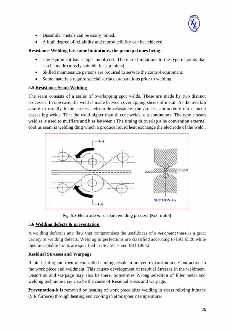
5.5 Resistance Seam Welding
The seam consists of a series of overlapping spot welds. These are made by two distinct
processes. In one case, the weld is made between overlapping sheets of metal As the overlap
assure th usually h the process, electrode resistance. the process automobile mu e metal
passes ing welds. That the weld higher than th cent welds, e a continuous. The type e seam
weld ss is used to mufflers and h es between t The timing ds overlap a he convention external
cool us seam is welding ding which a produce liquid heat exchange the electrode of the weld .
Fig. 5.3 Electrode wire seam welding process (Ref. nptel)
5.6 Welding defects & preventation
A welding defect is any flaw that compromises the usefulness of a weldment there is a great
variety of welding defects. Welding imperfections are classified according to ISO 6520 while
their acceptable limits are specified in ISO 5817 and ISO 10042.
Residual Stresses and Warpage
Rapid heating and then uncontrolled cooling result in uneven expansion and Contraction in
the work piece and weldment. This causes development of residual Stresses in the weldment.
Distortion and warpage may also be there. Sometimes Wrong selection of filler metal and
welding technique may also be the cause of Residual stress and warpage.
Preventation-it is removed by heating of work piece after welding in stress reliving furnace
(S.R furnace) through heating and cooling in atmospheric temperature.

27
Cracks-This is a serious welding defect appears as fracture type interruptions in the weld.
Crack works as a point of stress concentration so reduce the strength of the joint.
Preventation - Prevent by pre heating of work piece before the welding.
Cavities or Porosity-Porosity consists of small voids in weld metal formed by gases
entrapped During solidification. Shape of the voids may be spherical holes or Elongated
holes. Therecan be another type of voids named as shrinkage Voids formed due to shrinkage
of metal during solidification.
Preventation – reduce by back chipping and use good quality of flux.
Solid Inclusions-This is the entrapped non-metallic solid material. It may be the inclusion of
slag Generated in a welding process.
Preventation- Reduced by back chipping of material and grinding.
Incomplete Fusion-It is also called lack of fusion. It is a weld bead in which fusion has not
occurred throughout the entire cross-section of the joint. In other words it is a lack of
penetration. That is molten metal has not penetrated up to root of the joint.
Preventation- reduces by increase in welding current and mention proper gap between
work piece and electrode.
Imperfection in Shape For a particular type of edge preparation the weldment should
acquire a predefined Shape for maximum strength. If actual shape of weldment different from
the Predefined one it is called imperfect shape. It contributes to poor strength to the Welded
joint.
Preventation- prevented by give proper support to work piece and heating the work piece.
Undercut- Undercutting is when the weld reduces the cross-sectional thickness of the base
metal, which reduces the strength of the weld and workpieces. One reason for this type of
defect is a excessive current, causing the edges of the joint to melt and drain into the weld.
Prevention-It is prevented by using proper current and welding skill.
28
Chapter 6
CNC Machining Centre
6.1 INTRODUCTION
To keep pace with time and to meet the changing technological demand of the manufactured /
machined components, CNC Centre was established in 1988. Following three machines are
installed in CNC machining Centre.
1) CNC CHUKER HMT.STC.25
2) CNC VERTICAL MACHINING CENTRE PAL.VA.35
3) CNC 3-D MEASURING MACHINE CARL ZEISS UC550
6.2 CNC LATHE MACHINE
Computer numerical controlled (CNC) lathes are rapidly replacing the older production lathes
(multi-spindle, etc.) due to their ease of setting, operation, repeatability and accuracy. They
are designed to use modern carbide tooling and fully use modern processes. The part may be
designed and the tool paths programmed by supervision of an operator.
The machine is controlled electronically via a computer menu style interface, the
program may be modified and displayed at the machine, along with a simulated view of the
process. The setter/operator needs a high level of skill to perform the process, however the
knowledge base is broader compared to the older production machines where intimate
knowledge of each machine was considered essential. These machines are often set and
operated by the same person, where the operator will supervise a small number of machines
(cell)The design of a CNC lathe varies with different manufacturers, but they all have some
common elements. The turret holds the tool holders and indexes them as needed, the spindle
holds the workpiece and there are slides that let the turret move in multiple axis
simultaneously. The machines are often totally enclosed, due in large part to Occupational
health and safety (OH&S) issues.
Computer NC systems include additional features beyond what is feasible with
conventional Hard-wired NC. These features, many of which are standard on most CNC MCVs whereas others are optional, include the following:
6.3 FEATURES OF CNC
Storage of more than one part program. With improvements in computer storage
technology. newer CNC controllers have sufficient capacity to store multiple
programs.
Various form of program input. Whereas conventional (hard-wired) MCVs are
limited to punched tape as the input medium for entering part programs. CNC controllers generally possess multiple data entry capabilities, such as punched tape.
These machines have given us assured production with negotiable process rejections.
These machines enabled IL to indigenise various product ranges speedily. It would be much
faster to execute on-time order at minimum cost. For quick inspection of first work piece

29
produced by CNC machines & for random sampling of production runs, IL have CNC-3D
Co-ordinate measuring machine in CNC Centre.
CNC-3D Co-ordinate measuring machine is an advance, multipurpose quality control
system used to help the inspection to keep pace with modern requirements.
It replaces long, complex and inefficient conventional inspection methods with simple
procedures that are much faster as well as accurate. It reduces or eliminates CNC down time,
cuts down scrap and rework. A CMM can check the dimensional and geometric accuracy of
every item from big complex mechanical parts to flexible rubber, plastic moulded parts. It
measures virtually any part at any stage of production with exact precision and substantial
time savings.
Fig. 6.1 CNC lathe(Ref-IL)
CNC machine tool systems can be classified in various ways such as:
Point-to-point or contouring: Depending on whether the machine cuts metal while the work
piece moves relative to the tool.
Incremental or absolute: Depending on the type of coordinate system adopted to
parameterise the motion commands.
Open-loop or closed-loop: Depending on the control system adopted for axis motion control.
6.4 ABSOLUTE SYSTEM
An absolute NC system is one in which all position coordinates are referred to one fixed
origin called the zero point. The zero point may be defined at any suitable point within the
limits of the machine tool table and can be redefined from time to time. Any particular
definition of the zero point remains valid till another definition is made.
Considering the X-coordinate for point A as zero, the X-coordinate for points B and C
would be 50 and 70, respectively, in an absolute coordinate system. Most modem CNC
systems permit application of both incremental and absolute programming methods. Even
30
within a specific part program the method can be changed These CNC systems provide the
user with the combined advantages of both methods.
6.5 PART PROGRAMMING
As mention earlier, a part program is a set of instructions often referred to as blocks, each of
which refers to a segment of the machining operation performed by the machine tool. Each
block may contain several code words in sequence. These provide:
1. Coordinate values (X, Y, Z, etc.) to specify the desired motion of a tool relative to a
work piece. The coordinate values are specified within motion code word and related
interpolation parameters to indicate the type of motion required (e.g. point-to-point, or
continuous straight or continuous circular) between the start and end coordinates. The
CNC system computes the instantaneous motion command signals from these code
words and applies them to drive units of the machine.
2. Machining parameters such as, feed rate, spindle speed, tool number, tool offset
compensation parameters etc.
3. Codes for initiating machine tool functions like starting and stopping of the spindle,
on/off control of coolant flow and optional stop. In addition to these coded functions,
spindle speeds, feeds and the required tool numbers to perform machining in a desired
sequence are also given.
4. Program execution control codes, such as block skip or end of block codes, block
number etc.
5. Statements for configuring the subsystems on the machine tool such as programming
the axes, configuring the data acquisition system etc.
6.5 CNC Milling Machine
Milling is the machining process of using rotary cutters to remove material from a work piece
advancing (or feeding) in a direction at an angle with the axis of the tool. It covers a wide
variety of different operations and machines, on scales from small individual parts to large,
heavy-duty gang milling operations. It is one of the most commonly used processes in
industry and machine shops today for machining parts to precise sizes and shapes.
Milling can be done with a wide range of machine tools. The original class of machine
tools for milling was the milling machine (often called a mill). After the advent of Computer
Numerical Control, (CNC) milling machines evolved into machining centers (milling
machines with automatic tool changers, tool magazines or carousels, CNC control, coolant
systems, and enclosures), generally classified as vertical machining centers (VMCs)
and horizontal machining centers (HMCs).
The integration of milling into turning environments and of turning into milling
environments, begun with live tooling for lathes and the occasional use of mills for turning
operations, led to a new class of machine tools, multi-tasking machines (MTMs), which are
purpose-built to provide for a default machining strategy of using any combination of milling
and turning within the same work envelope. . It is one of the most commonly used processes
in industry and machine shops today for machining parts to precise sizes and shapes.

31
Fig.6.2 CNC Milling Machine
6.6 G-CODE & M-CODE
In the appendix-1 and appendix-2, we provide list of G and M-codes for the reader to have an
idea of the kind of functionality that can be realized using these codes. These codes were
originally designed to be read from paper tapes and are designed to direct tool motion with
simple commands.

32
CHAPTER 7
CONCLUSION
The Changing industrial environment need trained engineering man power at all levels and
accordingly engineers find placement in all functional areas like technical, research and
development etc.
As a student of B.Tech I was privileged to undergo training here at Instrumentation
Limited Kota, Here not only did I learn how to work in an industrial atmosphere, but also
learnt how to deal with the real life problems in the industry.
I have learnt about the working of industrial CNC Lathe machine and CNC Milling
machines and tool changing in CNC machines. I have learnt the Processes Planning in the
industry and how to reduces the time to get the maximum efficiency by the utilization of
advanced technology.
My visit to various departments of the industry gave me a clear idea about the working
of Industrial Machines, Which I think was helpful not only during my project but will also
help me to solve problems in any of the organization I will work in the coming future.

33
REFERENCES
1) Manual from Instrumentation Limited.
2) John A. Schey, Introduction to Manufacturing Process, McGraw Hill, 2000, 2nd
Edition, NY
3) R S Parmar, Welding Engineering & Technology, Khanna Publisher, 2002, 2nd
Edition, New Delhi.
4) Manual from CNC Centre of Instrumentation Limited.
5) Richard Little, Welding and Welding Technology, McGraw Hill, 2001, 1st Edition,
NY

34
APPENDIX-1
G-Codes
G00 - Rapid move (not cutting)
G01 - Linear move
G02 - Clockwise circular motion
G03 - Counter clockwise circular motion
G04 - Dwell
G05 - Pause (for operator intervention)
G08 - Acceleration
G09 - Deceleration
G17 - x-y plane for circular interpolation
G18 - z-x plane for circular interpolation
G19 - y-z plane for circular interpolation
G20 - turning cycle or inch data specification
G21 - thread cutting cycle or metric data specification
G24 - face turning cycle
G25 - wait for input to go low
G26 - wait for input to go high
G28 - return to reference point
G29 - return from reference point
G31 - Stop on input
G33-35 - thread cutting functions
G35 - wait for input to go low
G36 - wait for input to go high
G40 - cutter compensation cancel
G41 - cutter compensation to the left
G42 - cutter compensation to the right
G43 - tool length compensation, positive
G44 - tool length compensation, negative
G50 - Pre-set position
G70 - set inch based units or finishing cycle

35
G71 - set metric units or stock removal
G72 - indicate finishing cycle
G72 - 3D circular interpolation clockwise
G73 - turning cycle contour
G73 - 3D circular interpolation counter clockwise
G74 - facing cycle contour
G74.1 - disable 360 deg arcs
G75 - pattern repeating
G75.1 - enable 360 degree arcs
G76 - deep hole drilling, cut cycle in z-axis
G77 - cut-in cycle in x-axis
G78 - multiple threading cycle
G80 - fixed cycle cancel
G81-89 - fixed cycles specified by machine tool manufacturers
G81 - drilling cycle
G82 - straight drilling cycle with dwell
G83 - drilling cycle
G83 - peck drilling cycle
G84 - taping cycle
G85 - reaming cycle
G85 - boring cycle
G86 - boring with spindle off and dwell cycle
G89 - boring cycle with dwell
G90 - absolute dimension program
G91 - incremental dimensions
G92 - Spindle speed limit
G93 - Coordinate system setting
G94 - Feed rate in ipm
G95 - Feed rate in ipr
G96 - Surface cutting speed
G97 - Rotational speed rpm

36
G98 - withdraw the tool to the starting point or feed per minute
G99 - withdraw the tool to a safe plane or feed per revolution
G101 - Spline interpolation

37
APPENDIX-2
M-Codes Control Machine Functions
M00 - program stop
M01 - optional stop using stop button
M02 - end of program
M03 - spindle on CW
M04 - spindle on CCW
M05 - spindle off
M06 - tool change
M07 - flood with coolant
M08 - mist with coolant
M08 - turn on accessory (e.g. AC power outlet)
M09 - coolant off
M09 - turn off accessory
M10 - turn on accessory
M11 - turn off accessory or tool change
M17 - subroutine end
M20 - tailstock back
M20 - Chain to next program
M21 - tailstock forward
M22 - Write current position to data file
M25 - open chuck
M25 - set output #1 off
M26 - close chuck
M26 - set output #1 on
M30 - end of tape (rewind)
M35 - set output #2 off
M36 - set output #2 on
M38 - put stepper motors on low power standby
M47 - restart a program continuously, or a fixed number of times
M71 - puff blowing on

38
M72 - puff blowing off
M96 - compensate for rounded external curves
M97 - compensate for sharp external curves
M98 - subprogram call
M99 - return from subprogram, jump instruction
M101 - move x-axis home
M102 - move y-axis home
M103 - move z-axis home