integrating concurrent engineering concepts in a - researchgate
TRANSCRIPT

Integrating Concurrent Engineering Concepts in aSteelwork Construction Project
C. J. Anumba,1 A. N. Baldwin and D. Bouchlaghem
Department of Civil and Building Engineering, Loughborough University,Loughborough, LE11 3TU, UK
B. Prasad
CERA Institute, Unigraphics Solutions, P.O. Box 3882, Tustin, CA 92781-3882 USA
A. F. Cutting-Decelle, J. Dufau and M. Mommessin
Université de Savoie-ESIGEC/LGCH, Domaine de Savoie-Technolac, 73376 le Bourget du Lac, France
Received 8 December 1999; accepted in revised form 5 May 2000
Abstract: The aim of this paper is to present a methodology for integrating Concurrent Engineering (CE) concepts in a steelwork con-struction project. Differences between construction sector and manufacturing sector are first reviewed through the description of thespecificities of the construction sector in terms of organisations and main features projects.
The second part presents an integrated product and process model currently developed by the authors (ProMICE project). CE con-cepts are introduced according to a two axes methodology, a first axis describing the “working method” and a second providing a way ofrepresenting “CE knowledge” through the description of CE specificity. This axis also defines a way of “translating” those concepts intothe generic representation of the model.
One objective of the ProMICE project is to identify changes needed by this transition from the traditional approach towards CE ap-proach, then to represent them, in the domain of steelwork construction.
Key Words: integration, product and process modelling, UML, concurrent engineering, steelwork construction.
1. Introduction
The construction industry is notoriously fragmented witha typical project involving up to six or more different profes-sional disciplines. This has led to numerous problems includ-ing, inter alia, an adversarial culture; the fragmentation ofdesign and construction data (with data generated at onestage not being automatically available for re-use “down-stream”) and the lack of true life-cycle analysis of projects(including costing, safety assessment, maintenance, etc.) [1].It is now recognised that the adoption of new business pro-cesses based on Concurrent Engineering principles will pro-vide a means of overcoming these problems, and improvingthe competitiveness of the industry.
Previous studies have focused on modelling either theproduct or the process, without adequate consideration of theimplications of one on the other [2]. Indeed many researchprojects (some based on European initiatives) have been de-
Volume 8 Number 31531-2003/00/03 0199–14 $10.00/0 DO
© 2000 Technomic Pub
1Author to whom correspondence should be addressed.
voted to the description of the product to be designed orachieved with the aim of providing an “automated way” ofdesigning, archiving and exchanging data [3].
The inadequate infrastructure that exists for seamless pro-ject team communication has its roots in the structure of theconstruction industry. The use of disparate computer-aidedengineering (CAE) systems by most disciplines is one of theenduring legacies of this problem and makes information ex-change between project team members difficult and, in somecases, impossible. The integration of product and processmodelling will help to overcome this problem by enablingconstruction project teams to collaborate on the basis of ashared project model.
One of the aims of the work done within the ProMICE pro-ject is to provide an integrated product and process model forlife cycle design and construction of steelwork structures,enabling the introduction of Concurrent Engineering con-cepts. The ProMICE model is still under development. How-ever, first results provided by the analysis of the first twostages seem to be very promising in terms of contribution tothe initial objectives of the project.
199September 2000I: 10.1106/3A09-N3PN-H509-UV7Hlishing Co., Inc.

200 C. J. ANUMBA, A. N. BALDWIN, D. BOUCHLAGHEM, B. PRASAD, A. F. CUTTING-DECELLE, J. DUFAU AND M. MOMMESSIN
2. Analogy between Manufacturing andConstruction: Specificities, Organisation
2.1 Specificities of the Construction Sector
Specificity of the construction sector can be describedthrough several points, which are:
• construction features: one-of-a-kind nature of products,mainly site production, temporary combination of parts,regulatory interventions
• problems for developing new methods, or for taking newmeasures, given the lack of repetition of projects, the envi-ronmental uncertainty and the difficulty of data collectionon site
The peculiarities of this sector have usually been ad-dressed, either by eliminating unique solutions, so favouringstandard solutions, or by overcoming the problems of siteproduction, using prefabrication and pre-assembly, or elseby the formation of partnerships for production in a mutualeffort to overcome the problems of temporary multi-organi-zations, and corresponding temporary links.
The construction sector is also very complex, since it en-compasses both the building in itself, as well as the differentproducts used during the construction, such as steel, con-crete, prefabricated elements (beams, pre-stressed slabs, . . .),and various components (doors, windows, cladding and cov-ering elements, furniture, HVAC components, . . .). Accord-ing to the kind of construction product we refer to, the type offabrication will be different:
• whole building: project type• components (of whatever kind): batch processing• concrete (and other basic materials): continuous flow
production
It is also possible to observe a close correlation betweenthe complexity, measured by the number of different subsetsthe product is made of, the time factor, and the typology offabrication: project type manufacturing often takes monthsto be completed, usually with a complexity bigger than forbatch processing. This diversity in the manufacturing pro-cesses of the products to be used also contributes to create ad-ditional constraints that have to be taken into account duringthe construction process.
2.2 Organisation of the Operations
Construction [4] requires the application of a diverse pal-ette of resources to realize a finished facility (building orbridge). The organisation and application of these resourcescan be viewed in terms of the level at which decisions are be-ing made; that is, there is a construction hierarchy that is dic-tated by the way in which construction is organized. At thecompany level, decisions related to which projects to bid andthe recruitment of personnel are of interest. At the projectlevel, decisions regarding how long it will take to complete a
facility and the selection and movement of resources such asmachines and workers must be considered. Ultimately, how-ever, the project must be constructed. Physical items such asconcrete, glass, steel and a broad spectrum of materials mustbe erected, placed and installed to achieve the completed fa-cility. This is the production level in construction. This iswhere planning and design, analysis and control measurescome together to realize the end item—the facility.
Four levels or hierarchy can be identified, as follows:
• organizational: legal and business structure of a firm, thefunctional areas of management and the interaction be-tween head office and field agents performing these man-agement functions
• project: the vocabulary of this level is dominated by termsrelating to the breakdown of the project for the purpose oftime and cost control (e.g., project activity and project costcontrol). Also, the concept of resources is defined and re-lated to the activity as either an added descriptive attributeof the activity or for resource scheduling purposes.
• operation (and process): technology and details of howconstruction is performed. It focuses on work at the fieldlevel. Usually a construction operation is so complex thatit encompasses several distinct processes, each having itsown technology and work task sequences. However, forsimple situations involving a single process, the terms aresynonymous.
• task: identification and assignment of elemental portionsof work to field agents
2.3 Manufacturing Industry vs. Construction
Although constructed facilities themselves are typicallyunique, the methods used to construct them are often repeti-tive or cyclic in nature, as in the case of steelwork construc-tion, either for industrial buildings (with a layout of repetitiveportal frames), or for residential ones (with assemblies ofcolumns, or beams as needed for steelwork floors).
In manufacturing, the cornerstone of mass production isthe repetitiveness of the work to be performed. This is basedon the standardization of the product to be created. Standard-ization and modularization are historically well-known con-cepts for construction materials (e.g., brick and block sizes).The concept of standardization (of the shapes) to achieverepetition has been less successfully applied to the design ofconstruction processes, since it largely depends on the archi-tectural designer, the architect, most of the time fond of hisprerogatives.
However, recently, successes on large projects haveproved that design of process to achieve repetitiveness is thebasis for cost-effective construction, which also leads to highquality.
We must also notice the fact that industrial manufacturingis more and more moving towards a customization of theproducts (automotive industry, aerospace, or other mass pro-duction), with the same consequences on the type and the

Integrating Concurrent Engineering Concepts in a Steelwork Construction Project 201
methods of fabrication as already seen for the constructionsector.
3. Some Key Features of Concurrent Engineering
Concurrency and simultaneity are the major force of Con-current Engineering. Concurrency and simultaneity in Con-current Engineering can be achieved through seven enablingprinciples, which are:
3.1 Parallel Work-Group
Parallel work-groups are one of the key elements of theconcurrency described [5–7]. Paralleling describes a “timeoverlap” of one or more activities in the A-set, tasks, etc. CEis structured around multi-functional teams that bring spe-cialized knowledge necessary for the project.
• Multidisciplinary Project Team: The multidisciplinarysetup—called design and construction team (DCT)—iscomposed of several distinct project sub-units specializ-ing in a variety of areas: Property Planners, Clients orOwners; Structural Engineers, HVAC Engineers and ana-lysts; Architectural designers; Consultants & Regulators,Contractors & Partners; Cost Estimators; Materials Sup-pliers, Procurement teams; Fabricators, Assemblers andErectors; Facility Operators. A building’s constructionprocess is not a Concurrent Engineering process unless itinvolves all parties that are responsible for its fabrication,assembly and erection, regardless of who they report to ad-ministratively. Subcontracting companies must be in-cluded as participants in the CE teams, at least until theconstruction specifications have been determined, vali-dated, and are somewhat firmed up.
• Inclusion of Outside Contractors or Trade Partners: Theeffective inclusion of outside contractors or (consultant)partners in the cooperative construction is frequently oneof the under emphasized issues related to the implementa-tion of a CE process. In today’s environment because ofthe growth in the complexity of investments goods and ser-vices (buildings, bridges, etc.) and the increased relianceon ready-to-assemble pre-built building parts and trouble-free procurement methods to construct them, partnershiphas become an increasingly important issue. Building andcivil engineering industries often rely on outside contrac-tors or partners to supply materials, services and productsin various specialized forms and shapes.
3.2 Parallel Product Decomposition
Smith and Browne [8] and Los and Storer [9] describe de-composition as a fundamental approach to handling com-plexity in architectural design, engineering and constructionof a building. Property decomposition means viewing theproperty construction process as a part of the whole and then
overlapping (aggregating) the decomposed A-sets to recreateor reconstruct the whole set (IDC-set) from its parts (A-sets).In other words:
Property Construction ⇔
[Decomposing (parts-from-the-whole)
⊕ Reconstructing (whole-from-the-parts)]
The term “whole” also includes multiple characteristics oflife-cycle concerns (e.g., X-ability). Although not all life-cy-cle activities are independent, many sets can be decomposedsafely. For example, it is not necessary to delay the start of anactivity if the information required for that activity is not de-pendent on the rest. Due to an increased global pressure toconstruct a building or a facility as early as possible, parallelprocessing in CE is becoming a necessity [10]. The two stepsprocess shown in equation is in line with the way a contract-ing company builds a property. Usually, the design team pro-duces the detailed design of a building from top-to-bottom,but when the construction starts, the structure is fabricated orerected from bottom-up. There are, however, many ways abuilding, a facility, a construction process or work informa-tion can be decomposed and overlaid in parallel [11]. If aproperty, construction process or a work information activitydoes not affect other parameters (such as safety or regulatorycodes), it can be performed locally. If it does, it can be per-formed in a distributed fashion. Local or distributed process-ing, to a large extent, depends on how a property’s structure isoriginally broken up or decomposed [5]. Do the decomposedparts exhibit independent or semi-independent characteris-tics? Decomposition allows the scheduling of activities toproceed in parallel. In a construction process, usually a highdegree of dependencies exist, as such it becomes even moreimportant that such decomposition of construction proper-ties is done in the right way.
The two (decomposition + concurrency) allow one to iden-tify activities that can be overlapped or performed simulta-neously. It also allows one to formulate strategies leading totheir separation, e.g., indexing, alternate decomposition,teaming, or restructuring. Meaning they are coupled and can-not be separated explicitly either in a series or in a parallelmode. Interdependent (or coupled) activities take more de-sign time and many iterations (of information transfer backand forth) before they finally converge. The aim of CE is si-multaneous, immediate interaction. In practice, however,mutually independent group of activities seldom exist. Stra-tegically, decomposing the interdependent activities into aseries of dependent, semi-independent and independent ac-tivities can reduce the size of the working groups and thenumber of iterations that is required to obtain a reasonablesolution.
3.3 Concurrent Resource Scheduling
Facilitating the transfer of work information among work-

202 C. J. ANUMBA, A. N. BALDWIN, D. BOUCHLAGHEM, B. PRASAD, A. F. CUTTING-DECELLE, J. DUFAU AND M. MOMMESSIN
groups is an essential organizational task of any constructioncompany. Concurrent resource scheduling involves schedul-ing the distributed activities so that they can be performed inparallel. Paralleling is simple for activities exhibiting inde-pendent or semi-independent characteristics, however, it isnot so simple for dependent activities set. There are manycases when activities are dependent (not yet coupled) butneed to be scheduled in parallel with other activities. A sim-ple case is that of an overlap. Even though an activity is de-pendent on another, there is no need for one to wait until theother task ends. If an activity precedes and generates theneeded information for a later activity, the next task can startas soon as the needed information is made available. There isno need to wait for the completion of the former task. If thetwo activities are independent, they can be scheduled in anyorder necessary. The other options that address these issuesmore precisely are: optimal scheduling (minimizing time, re-source, cost, etc.), backward scheduling (meeting targettime), and team-based project management. Sanborn Manu-facturing Company employed a backward scheduling to setup major milestones consisting of hard and fast dates andworked back from those dates as a planning mechanism [12].
Frequently a building is radically redesigned to achieveparallelism. Paralleling of activities provides the manage-ment team with opportunities to reorganize and control theresources applied during CE. These resources fall into threemain categories: teams [e.g., people, machines (cranes, lad-ders, etc.), facilities (materials, outside firms, etc.)]; tasks(activities or projects they work on, knowledge of the pro-jects, information they need to work with) and time. The trioprovides a basis for defining a work breakdown structure, se-ries of interrelated work tasks initially set in motion by theplanning track. New tasks are added or created by the subse-quent tracks when put into motion. The latest series of tasksare mostly due to construction specifications, cost manage-ment, and procurement and supply tracks.
3.4 Concurrent Processing
Managing time is the fulcrum of Concurrent Engineering.Some companies rely on milestones. Others use strategicrouting and queuing as another way to manage time. Concur-rent Processing means optimal routing and queuing of activi-ties both from the work-group distribution and informationbuildup standpoint. This is essential to guide the architec-tural design of the property and its fabrication, assembly anderection processes toward a safety, quality-build end. Con-current Processing is never easy, particularly in industrialsettings where solvable technical problems are prevailedupon by cultural considerations. Resistance to change isquite predominant. This is seen, for example, in the automo-tive industry, and more generally, in companies where theage profile of the technical staff is high. The three most im-portant concepts associated with Concurrent Processing are:creation of “variable-driven” product/process models, routemanagement and queue management.
In concurrent processing, activities are staggered (per-formed simultaneously or overlapped) rather than carried outsequentially. Keeping track of those complex dependenciesthat vary with time is a critical task in concurrent processing.Appropriate synchronization efforts between different CEteams have to be made.
3.5 Minimize Interfaces
This entails reducing all types of interfaces required forthe “Product Realization Process” to a bare minimum. Theseinclude the interface relationship between project definitionand architectural design, construction specification and costmanagement, architectural design and structural engineer-ing, cost management and procurement, fabrication, assem-bly and erection interface, procurement and supply design,etc. Such interfaces can be very long indeed and tend to de-pend upon the size of the industry, and the construction facil-ity and process complexity. Partitioned design and construc-tion can be facilitated by introducing adequate interfacemanagement. The main focus is on identifying varioussources of interfaces and determining whether they are actu-ally needed or not.
3.6 Transparent Communication
This provides virtual communication between the individ-ual activities that are partitioned (decomposed), and betweenthe team members. Transparent communication involvesidentification and definition of mission-critical data. Allmembers of the CE teams need to have the same common un-derstanding of the frequently used terms and their meanings.It may require definition of “data dictionary and semantics”as a structured approach to resolving conflicts and for con-sensus building. The elements that contribute to transparentcommunications are (a) global access (b) Universal ProductRepresentation (STEP) (c) Electronic Data Interchange(EDI) (d) Technical memory.
3.7 Quick Processing
Quick Processing means performing individual activitiesas fast as possible using productivity tools or design aids. Italso amounts to speeding up the preparation time in buildingup the information content before and after an execution ofan activity. This emphasizes the mandate for shortening thepre- and post-processing time and the time it takes for com-pleting the decomposed activities themselves.
4. The ProMICE Integrated Productand Process Model
4.1 The ProMICE Project
ProMICE (Product and Process Models Integration for

Integrating Concurrent Engineering Concepts in a Steelwork Construction Project 203
Concurrent Engineering in Construction) is a collaborativeresearch project between the Department of Civil and Build-ing Engineering at Loughborough University, UK and theEcole Supérieure d’Ingénieurs de Chambéry, Université deSavoie, France. It is funded jointly by the British Council andthe French Government [13].
4.2 Objectives of the Project
The aim of the project is to compare and link British andFrench approaches to product and process modelling with aview to developing a generic integrated model based on CEprinciples. The specific objectives of the project include:
• review and comparison of the use of product and processmodels in the construction industry in Britain and inFrance
• development of a generic integrated product and processmodel for design and construction, based on concurrentengineering principles. The generic model will embodythe best features of French and British practice, and as faras possible will be developed as a conceptual model, inde-pendent of implementation constraints.
• investigation of the requirements for computer-aided de-sign (CAD) and information technology (IT) systems—including virtual reality (VR)—to support the genericproduct and process model. These requirements will formthe basis for a software architecture for the implementa-tion of the model.
The concurrent engineering (CE) framework within whichthe integration of the product and process models is being un-dertaken is innovative and incorporates the best features ofCE implementation in the manufacturing industry.
4.3 Work Programme
To achieve the goals defined for the project, the work hasbeen split into five tasks, which are:
• identify available models: for data and processes (UK andFrance)
• identify available representation methods• agree on common methods, for data and processes• elaborate a synthesis of the models to produce the generic
integrated product and process model• identify CAD and IT requirements and formulate a soft-
ware or logical architecture for the generic model
4.4 Applicability
It is intended that the integrated product and processmodel will facilitate improvements in the construction pro-cess, particularly with respect to: collaborative design, pro-ject co-ordination, reduction in project duration, reduction incosts, reduction in claims and disputes, and improvements inproduct quality. The generic model will be applicable to dif-
ferent European countries, many of which have similarlyfragmented construction industries. The project also contrib-utes to the ongoing international work on product and pro-cess improvements in construction, and will inform about thedevelopment of appropriate international standards, such asthe standards being developed within the ISO TC 184/SC 4“Industrial Data”: ISO 10303 STEP (STandard for the Ex-change of Product model data) and ISO 15531 MANDATE(MANufacturing DATa Exchange) [14,15]. This project willalso inform about the IAI (International Alliance forInteroperability), in charge of the development of the IFCs(Industry Foundation Classes).
4.5 Areas of Potential Concurrency during theLife-Cycle Phases of a Construction Project
The different life-cycle phases of a construction projectcan be detailed into eight “tracks” [16], which are: inceptionand project definition, outline design, structural engineeringand analysis, property specifications, cost management, pro-curement and supply, fabrication, assembly and erection, andfinally facility management. The track “facility manage-ment” is an ongoing coordination track that runs for the fullconstruction life cycle, also providing normal project man-agement functions, tasks sequencing, cooperation and cen-tral support to the other tracks. These eight tracks are notunique to a particular construction facility (such as buildings,bridges, roads, factories, etc.). Individual tasks breakdown,their identifying names and time overlaps may differ fromproject to project. Figure 1 represents possible areas ofconcurrency during these phases. As we will see, the focus ofthe ProMICE project has been put on the design stages of aconstruction project.
4.6 Modelling Approach
Following a preliminary review of modelling languagesable to represent both product and process information, theproject team decided to use the Unified Modelling Language(UML) [17], as it offered the potential for achieving theProMICE objectives [2].
UML is not a modelling method in itself, rather a model-ling notation, or more, a graphical modelling language usedto describe, most of the time, software development pro-cesses. Constitutive elements of the language are modellingelements and diagrams: UML defines nine diagrams, four ofthem bringing a “static view” (Class, Object, Component,Deployment diagrams) and five a “dynamic view” (UseCase, Sequence, Collaboration, Statechart, Activity dia-grams).
It is important to notice that a diagram is not a model, butonly a partial graphical representation of some elements ofthe model: a diagram is a projection onto the model, as a kindof perspective on the model. Several diagrams are necessaryto illustrate the entire model.
One of the problems we met when we started the represen-

204 C. J. ANUMBA, A. N. BALDWIN, D. BOUCHLAGHEM, B. PRASAD, A. F. CUTTING-DECELLE, J. DUFAU AND M. MOMMESSIN
Inception and project definition
Outline design
Structural engineering and analysis
Construction specifications
Cost management
Procurement and supply
Fabrication, assembly and erection
Facility management
Property
Progressive enrichment
LEGEND :
Requirements
Constraints
Changes and revisions
Enrichment
Feedback
Figure 1. Areas of potential concurrency.
tation of the model with UML was the determination of thetypes of UML diagrams to be developed and their sequence,since the subject of our development is different enoughfrom the common usage of the language, notably the natureof the system to be described. The system we need to repre-sent (and of which we want to know, the behaviour throughthe knowledge of elements and diagrams) is made of the de-sign team (architect, engineers, project manager) involved ina building construction project.
For the ProMICE project, we decided to focus our work onthe design stage of a construction project, without consider-ing the full life cycle of the building, since this stage can beconsidered as belonging to the “decisional core” of the con-struction process. It is a critical stage where inappropriate de-cisions can have big consequences on subsequent stages, thiscan be prevented if problems are identified during the earlystages of the project.
Compared to software development, the specificity of theuse we make of the language lies in the way of defining thespecifications of the system: specifications of a building pro-ject are known at the beginning, since they have been definedby the project owner.
Activities of the actors involved in the project are definedthrough activity diagrams and sequence diagrams. These se-quence diagrams provide a powerful representation of the se-
quencing of the different activities, through the descriptionof “working scenario” of the actors involved, thus enabling adetection of possible “strategic crossings” that could be im-proved using CE features. Figure 2 shows an example of a se-quence diagram.
Case diagrams can be used to provide a high level view onthe (main) actors involved in the “system” considered. Arough representation of the outline design stage is shown inFigure 3.
The names of all the actions have not been represented onthe diagram, for readability reasons. However, in the finalversion of the project, all the diagrams will be provided withtheir glossary. It is interesting to represent at the same timeactivity diagrams, since they provide a complementary view,emphasizing the flows of control among the actors and theiractivities. Figure 4 shows an example of an activity diagramrelated to the outline design stage.
4.7 Current State of the Model
To date, the development of UML diagrams (activity, se-quence, use case, collaboration, deployment and state) is on-going, mainly focused on the design stage and the related ac-tors and tasks of the construction project. In order to facilitatethe description of a construction project, not the same ac-

Integrating Concurrent Engineering Concepts in a Steelwork Construction Project 205
Client / PM Architect Structural Eng. Services Eng. QS
orders
sendsOutlineDesign
asksAdjustmentIf needed
End If
While
not
approved
While modifications needed
then
End
If wrong
End If
Clarify specifications if needed
costAppraisal
While modifications needed
While modifications needed
End
End
then
then
proposesStructure
Figure 2. Sequence diagram: design stage—traditional approach.

206 C. J. ANUMBA, A. N. BALDWIN, D. BOUCHLAGHEM, B. PRASAD, A. F. CUTTING-DECELLE, J. DUFAU AND M. MOMMESSIN
OUTLINE DESIGN STAGE :
UML Use case diagram
Architect
Structural
engineer
Services
engineer
QS
function
set up
constraints
statutory
undertaker
local
authorities
Health and Safety
Executive
City
planners
architectural
design
validate the
project
structural
design
services
design
outline
cost plan
contractor
client/
PM
set up constraints :
only for PM
- not in TA
- CE : assess the
buildability
Figure 3. Use case diagram: outline design stage.

Integrating Concurrent Engineering Concepts in a Steelwork Construction Project 207
Figure 4. Activity diagram: design stage.
cording to the nature of the bid or the country, we decided,for a first stage, to separately represent the two models(in France and in the UK). It has then been possible tofind a common representation of the project, valid forboth countries, on which we are now introducing CEconcepts. The validation is made on a steelwork buildingproject.
5. Introduction of CE Conceptsinto the ProMICE Model
5.1 Methodology
Concurrent Engineering features are introduced in themodel according to a three-stage methodology we developedfor this project.
The aim of this methodology is twofold: first, we have todefine the way of working, that is to define the set of proce-dures necessary to introduce concurrent engineering con-cepts into the model; another feature of this methodology isto provide a way of representing “CE knowledge,” that ishow to describe CE specificity in order to introduce the re-
lated concepts in the model. In a second stage, it is thus nec-essary to “translate” those concepts into the generic repre-sentation provided by the model resulting from theintegration.
5.2 Stages of the Work
The three stages of the method followed in the ProMICEproject are:
• Stage 1: description of the current situation (traditionalapproach) in terms of the actors involved in the construc-tion process and in terms of the information flows
• Stage 2: description of a CE way of working (using thesame tools as in Stage 1)
• Stage 3: define changes to facilitate the transition from thecurrent situation to a CE way of working.
STAGE 1: CURRENT SITUATION,TRADITIONAL APPROACH
This stage used decisional tools, such as behaviouralgraphs and templates to be completed for each actor at eachstage of the design-construction process, nonetheless re-

208 C. J. ANUMBA, A. N. BALDWIN, D. BOUCHLAGHEM, B. PRASAD, A. F. CUTTING-DECELLE, J. DUFAU AND M. MOMMESSIN
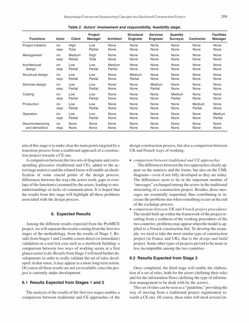
stricted, for the analysis, to the design stage. The first tem-plate was used to define the functions included in the designprocess at every stage from inception to scheme design (Ta-ble 1). The actors’ involvement and responsibilities at everystage are then shown on another set of templates using fourlevels of involvement (None, Low, Medium and High) andthree classes of responsibilities (None, Partial and Total), anexample of this is shown in Table 2. At this stage, it is impor-tant to mention that all the diagrams represented already re-sult from a synthesis of the structure of a construction projectbetween the two countries involved in the work.
Table 1. Definition of functio
Functions Inception Feasibilit
Project initiation Examine the present cir-cumstances and con-sider the need to build.Set up project team.
Conduct user stuand provide furthformation. Consisibility report andvelop brief.
Management Liaise with client andobtain background in-formation, budgets, re-quirements and time ta-bles about the site.
Survey and site sand locality. Constatutory authoritPrepare feasibilitport, site meeting
Architectural design Discuss terms of ap-pointment:Service providedBasis of fees.
Carry out site stuAttend meeting,preparation of thport. Obtain outliplanning consen
Structural design Discuss terms of ap-pointment:Service providedBasis of fees.
Carry out studiessite. Obtain additinformation. Conto meetings andin feasibility stud
Services design Discuss terms of ap-pointment:Service providedBasis of fees.
Carry out studiessite. Obtain additinformation. Conto meetings andin feasibility stud
Costing Discuss terms of ap-pointment:Service providedBasis of fees.
Obtain additionamation. Attend mand assist with feity studies, buildi& tenders.
Production Discuss site operationsand running of site.
Assist in preparafeasibility report,tend meetings anwith client.
Operation Discuss terms of ap-pointment:Service providedBasis of fees.
Carry out studiessite. Obtain additinformation. Conto meetings andin feasibility stud
Decommissioningand demolition
Consider life cycle andduration of building andoccupants.
Obtain additionamation. Contribumeetings and asfeasibility study.
STAGE 2: CONCURRENT ENGINEERING APPROACHThe same working procedure is then applied to the CE ap-
proach of the same construction project. The same decisionaltools are used: matrix representation and forms (same as fortraditional approach). The result of the matrix analysis is alsoavailable on a table showing the actors and the stage of theirintervention.
STAGE 3: TRANSITION FROM TRADITIONALTO CE APPROACH
This stage is not yet fully developed. Work is ongoing. The
ns in the design process.
Stages
y Outline Proposal Scheme Design
dies,er in-der fea-
de-
Receive and appraisedesigns and reports.Approves costs andmakes decision to pro-ceed.
Approve full design andcosts. Authorise formalapproval for statutoryconsent.
tudysulties.y re-s.
Co-ordinate the devel-opment of the outlineproposal and amendbrief. Report to client.
Co-ordinate design andprepare full scheme andreport to client. Applyfor planning consents.
dies.assist ine re-ne-t.
Carry out outline pro-posals and contribute tomeetings and prepara-tion of report.
Prepare full scheme de-sign and pass drawingsto QS. Prepare draft re-port.
onionaltributeassisty.
Contribute to meetingsand carry out furtherstudies. Prepare outlinedesign proposals.
Assist QS in finalise costplan, and contribute toscheme design and re-port.
onionaltributeassisty.
Contribute to meetingsand carry out furtherstudies. Prepare outlinedesign proposals.
Assist QS in finalise costplan, and contribute toscheme design and re-port.
l infor-eetingsasibil-ng cost
Contribute to meetingsand carry out furtherstudies. Prepare outlinecost proposals andplan.
Develop and finalisecost plan. Contribute toreport.
tion ofand at-d liaise
Contribute to the prepa-ration of the report andadvise on buildability.
Assist in building sched-ules and advise onbuildability.
onionaltributeassisty.
Contribute to meetingsand carry out furtherstudies. Prepare outlinedesign proposals.
Liaise with client, QSand engineers to helpwith the preparation ofthe final report.
l infor-te tosist in
Obtain further informa-tion. Contribute to meet-ings and assist in feasi-bility study.
Liaise with client, QSand engineers to helpwith the preparation ofthe final report.
Integrating Concurrent Engineering Concepts in a Steelwork Construction Project 209
Table 2. Actors’ involvement and responsibility, feasibility stage.
Functions Actor ClientProject
Manager ArchitectStructuralEngineer
ServicesEngineer
QuantitySurveyor Contractor
FacilitiesManager
Project initiation inv High Low None None None None None Noneresp Total Partial None None None None None None
Management inv Medium High None None None None None Noneresp Partial Total None None None None None None
Architectural inv Low Low Medium None None None None Nonedesign resp Partial Partial Partial None None None None None
Structural design inv Low Low None Medium None None None Noneresp Partial Partial None Partial None None None None
Services design inv Low Low None None Medium None None Noneresp Partial Partial None None Partial None None None
Costing inv Low Low None None None Medium None Noneresp Partial Partial None None None Partial None None
Production inv Low Low None None None None Medium Noneresp Partial Partial None None None None Partial None
Operation inv Low Low None None None None None Mediumresp Partial Partial None None None None None Partial
Decommissioning inv None None None None None None None Noneand demolition resp None None None None None None None None
aim of this stage is to make clear the main points targeted by atransition process from a traditional approach of a construc-tion project towards a CE one.
A comparison between the two sets of diagrams and corre-sponding glossaries (traditional and CE), added to the ac-tor/stage matrices and the related forms will enable an identi-fication of some crucial points of the design process:differences between the ways the actors work, gaps or over-laps of the function(s) assumed by the actors, leading to mis-understandings or lacks of communication. It is hoped thatthe results from this stage will highlight all these problemsassociated with the design process.
6. Expected Results
Among the different results expected from the ProMICEproject, we will separate the results coming from the first twostages of the methodology, from the results of Stage 3. Re-sults from Stages 1 and 2 enable a more direct (or immediate)validation on a real test case such as a steelwork building: acomparison between two ways of working seems at a firstglance easier to do. Results from Stage 3 will need further de-velopments in order to really validate the set of rules devel-oped: in that sense, it may appear as a more long term action.Of course all these results are not yet available, since the pro-ject is currently under development.
6.1 Results Expected from Stages 1 and 2
The analysis of the results of the first two stages enables acomparison between traditional and CE approaches of the
design-construction process, but also a comparison betweenUK and French ways of working.
• comparison between traditional and CE approachesThe differences between the two approaches clearly ap-
pear on the matrices and the forms, but also on the UMLdiagrams—even if not fully developed as they are today.The differences seem to lie in the important number of“messages” exchanged among the actors in the traditionalstructuring of a construction project. Besides, those mes-sages are essentially sequential, thus contributing to in-crease the problems met when something occurs at the endof the exchange process.
• comparison between UK and French project proceduresThe model built up within the framework of the project re-sulting from a synthesis of the working procedures of thetwo countries, problems may appear when the model is ap-plied to a French construction bid. To develop the exam-ple, we tried to take the most similar type of constructionproject (in France and UK), that is the design and buildproject. Some other types of projects proved to be more orless incompatible among the two countries.
6.2 Results Expected from Stage 3
Once completed, the third stage will enable the elabora-tion of a set of rules, both for the actors (defining their role)and for the information flows (defining the type of informa-tion management to be dealt with by the actors).
This set of rules can be seen as a “guideline,” providing theway of moving from a traditional project organisation to-wards a CE one. Of course, these rules will need several (in-

210 C. J. ANUMBA, A. N. BALDWIN, D. BOUCHLAGHEM, B. PRASAD, A. F. CUTTING-DECELLE, J. DUFAU AND M. MOMMESSIN
dustrial) validations, to refine the values of the different pa-rameters.
6.3 Industrial Validation of the Final Model
One of the objectives of the ProMICE project is to identifythe changes needed by this transition from traditional to-wards CE approach, then to represent those changes, notablyin the domain of steelwork construction and to write guide-lines to help users. The objective is also to provide an indus-trial validation of the final model. This validation will bemade on a steelwork building, chosen since this type of con-struction provides a better “traceability” of the work done bythe different teams involved in the project. It also enables usto rely on several results (in terms of communication and in-formation exchanges) of the Eureka EU130 CIMSteel Pro-ject on which one of the ProMICE partners has worked formany years.
7. Conclusions
At the heart of any good outline design, construction andprocurement process, there lies a set of underlying principlesfor satisfying the interests of the clients, the contractingbody, and the company.
This paper focuses on the presentation of these principles,in a context of Concurrent Engineering, allowing the con-struction project teams helps formulate significant outlinedesign and construction process strategies.
The introduction of these CE concepts has then been pre-sented through the work achieved within the framework ofthe ProMICE project, both in terms of the methodology car-ried out in the project and in terms of ongoing work.
The final stage of the work will be to represent and validatethe changes needed for the transition from the traditional pro-cess to Concurrent Engineering using the case of a steelframe building.
This will enable the project team to make use of methodol-ogies in communication and information exchange alreadycarried out and used within the Eureka CIMSteel Project.
References
1. Anumba C.J. and N.F.O. Evbuomwan 1997, “Concurrent En-gineering in Design-Build Projects,” Construction Manage-ment and Economics, 15(3):271–281.
2. Anumba C.J., Cutting-Decelle A.F., Baldwin A.N., Dufau J.,Mommessin M., Bouchlaghem N.M., “Integration of Productand Process Models as a Keystone of Concurrent Engineeringin Construction: The ProMICE Project,” Proceedings of 2ndEuropean Conference on Product and Process Modelling,Amor R. (Ed.), 1998.
3. Dubois A.M., Flynn J., Verhorf M.H.G., Augenbroe, F., “Con-ceptual Modelling Approaches in the COMBINE Project,” Fi-nal Combine Workshop Paper, Dublin, 1995.
4. Halpin D.H., Riggs L.S., Planning and Analysis of Construc-tion Operations, J. Wiley, 1992.
5. Prasad B., Concurrent Engineering Fundamentals, Vol I:Integrated Product and Process Organization,Vol II:Integrated Product Development, Prentice Hall PTR, 1996.
6. Prasad B., Concurrent Engineering Fundamentals, Vol I:Integrated Product and Process Organization,Vol II:Integrated Product Development, Prentice Hall PTR, 1996.
7. Krishnan V., “Design Process Improvement: Sequencing andOverlapping Activities in Product Development,” D.Sc. The-sis, Massachussetts Institute of Technology, 1993.
8. Smith G.F. and Browne G.J, “Conceptual Foundations of De-sign Problem Solving,” IEEE Transactions on Systems, Man,and Cybernetics, Vol. 23, No. 5, September–October, 1993.
9. Los R. and Storer G., “Taking Control of the Building Pro-cess,” Proceedings of the Ist International Conference on Con-current Engineering in Construction, The Institute of Struc-tural Engineers, London, 1997.
10. Kamara J.M., Anumba C.J., N.F.O. Evbuomwan, “Consider-ation for the Effective Implementation of the Concurrent Engi-neering in Construction,” Proceedings of the 1st InternationalConference on Concurrent Engineering in Construction, TheInstitute of Structural Engineers, London, UK, 1997.
11. Kusiak A., Wang J., “Decomposition of the Design Process, J.of Mech Design,” Trans of the ASME, Vol. 115, No. 4, 1993.
12. Machine Design, Vol. 65, No. 23, Nov. 1993, pp. 77–80.
13. Anumba C.J., Cutting-Decelle A.F., Baldwin A.N., Dufau J.,Mommessin M., Bouchlaghem N.M., “Introduction of Con-current Engineering Concepts into an Integrated Product andProcess Model,” Concurrent Engineering in ConstructionConference, 1999.
14. Cutting-Decelle A.F., Deuse J., Michel J.J., “Standardizationof Industrial Manufacturing Management Data: the MAN-DATE (ISO 15531) Approach,” Product Data TechnologyDays, London 1998.
15. Cutting-Decelle A.F., Dubois A.M., Fernandez I., Manage-ment and Integration of Product Information in Construction,Reality and Future Trends,” International Journal of Con-struction Information Technology,Vol 5, no. 2, 1997.
16. Prasad B., “Towards Applying Principles of Concurrent Engi-neering for Efficient Design and Development of ConstructionFacilities,” submission to CIDAC Journal, 1998.
17. Unified Modelling Language, V. 1.1, Rational Software, 1997.
Chimay Anumba
Dr. Chimay Anumba is a Char-tered Civil/Structural Engineer. Heis currently Reader in Computer-In-tegrated Construction and foundingDirector of the Centre for Innova-tive Construction Engineering(CICE) at Loughborough Univer-sity. Dr. Anumba is also Editor-in-Chief of the International Journal ofComputer-Integrated Design andConstruction, CIDAC. His researchinterests are in the fields of com-
puter-aided engineering, concurrent engineering, IT, knowl-edge-based systems, collaborative communications, struc-

Integrating Concurrent Engineering Concepts in a Steelwork Construction Project 211
tural engineering, and project management. He has over 140scientific publications in these fields. Dr. Anumba’s re-search work has received support with a total value of over£6m from industry, the Engineering and Physical SciencesResearch Council (EPSRC), and several UK and interna-tional funding bodies. He is actively involved in several pro-fessional bodies and is a member of the governing Councilof the Institution of Civil Engineers (ICE). Dr. Anumba alsoundertakes advisory and consultancy work for the UK gov-ernment and construction-sector firms and has recentlyspent time at the Massachusetts Institute of Technology(MIT) as a visiting Professor & Scholar.
Andrew Baldwin
Prof. Andrew Baldwin C EngMICE, FCIOB, is a chartered CivilEngineer with extensive industryand academic experience. He haswritten several books and publishedover 70 papers in refereed academicjournals and conference proceed-ings. His current research interestsare focused on process modellingand the use of ICT to support theconstruction process. Current pro-jects include the development of
new tools and techniques for improving design manage-ment and the use of concurrent engineering and collabo-rative working and to improve supply chain communica-tions.
Dino Bouchlaghem
Dr. Dino Bouchlaghem is a quali-fied architect. He is currently a se-nior lecturer in the department ofCivil and Building Engineering atLoughborough University. His re-search interests are focussed on In-formation Technology applied tobuilding design and construction.He has published over 50 papers inrefereed academic journals and con-ference proceedings. Current pro-jects include; IT Tools and Support
for Improved Construction Briefing, Virtual Reality Appli-cations in the House Building Industry, Visualisation of Per-formance Data sets using Synthetic Environments, The Use
of Information Technology and Visualisation Techniques toImprove the Communication of Detail Design Informationto Construction Sites, Improving User Feedback in BuildingDesign using Post Occupancy Evaluation.
Biran Prasad
Dr. Prasad is the Director, Knowl-edge-Based Engineering ProductBusiness Unit at Unigraphics Solu-tions (UGS) in California, USA.Before joining UGS in 1998, he wasthe Principal Consultant and Direc-tor of Concurrent Engineering Ser-vices at Electronic Data Systems(EDS) (an ex-subsidiary of GeneralMotors), where he was in charge ofAutomated Concurrent Engineeringconsulting Group since 1985.
He has written or co-authored over 100 technical publica-tions, including 70 archival papers and a dozen books. Hewrote a new Textbook on “Concurrent Engineering Funda-mentals,”—a two volume set—published by Prentice Hall,USA. The textbook is followed in many universities. His ed-ited text is Modern Manufacturing: Information Manage-ment and Control (1994), published by Springer Verlag. In1989, he edited a set of three-volume book entitledCAD/CAM, Robotics and Factories of the Future, 1989,Springer-Verlag. He has served as editor for several addi-tional texts, monographs and proceedings. He supports pro-fessional societies in several editorials and organizationroles. He has received three awards: AIAA’s Survey PaperCitation Plaque & Award (1982), a NASA Award and a Cer-tificate for Creative Development of a Technical Innovationon “PARS”—Programs for Analysis and Resizing of Struc-tures (1981), and the ABI (American Biographical Institute)Commemorative Medal of Honor (1987). Dr. Prasad is theManaging Editor for the International J. of Concurrent Engi-neering: Research & Applications (CERA).
Dr. Prasad earned his Ph.D. from Illinois Institute of Tech-nology, Chicago, a Degree of Engineer from Stanford Uni-versity, California. He received a Master (M.S.) degree fromIndian Institute of Technology, Kanpur and a B.E. Degreefrom Bihar College of Engineering, Patna, both from India.Dr. Prasad has served on numerous committees for ASCE,ASME and SAE. He is the Chairman of the SAE’s ComputerReaders’Committee. His professional honors include: Asso-ciate Fellow of AIAA, Fellow of ASME, ASCE, SAE,AAAI, and fellow and life member of ISPE.
Anne-Françoise Cutting-Decelle
Dr. AF Cutting-Decelle studied atthe Ecole Normale Supérieure(Cachan) where she graduated asAgrégée in Civil Engineering in1979. She got her PhD at the LGCHlaboratory, she has been assistant-professor, first at the Civil Engi-neering department of the Univer-sitary Institute of Technology(Cergy), then at the Ecole Supér-ieure d’Ingénieurs de Chambéry.Her research activities are mainly
focused on data and process modelling in the constructiondomain but also on the contribution of Information Technol-ogies to the integration of technical data in building con-struction. She works as expert for several standardizationcommittees, in France (AFNOR), and at the European level(CEN) in the domain of Advanced Manufacturing Technol-ogies. Her work is focused on the standardization of productand process management data, on the integration of the re-lated models and on the joint application of the standardsemerging from these works: STEP and MANDATE.
Jacques Dufau
J. Dufau studied at the INSA(Lyon), where he graduated as engi-neer in Civil Engineering in 1970.He became Docteur Ingénieur inCivil Engineering since 1975 andDocteur es Sciences in Civil Engi-neering since 1981. He has beenProfessor at the Ecole Supérieured’Ingénieurs of the University ofSavoie, in Chambéry since 1983.For five years, from 1994 to 1998 hehas been Head of the Ecole
Supérieure d’Ingénieurs.As a member of the Laboratoire Génie Civil et Habitat, his
research activities are mainly focused on aided design toolsand systems, especially dedicated to building design. Heparticularly works on data modelling and engineering or-ganisation.
Michel Mommessin
Michel Mommessin studied atEcole Centrale (Lyon) where hegraduated as engineer in 1976. Hegot his PhD in civil engineering in1981 and became assistant-profes-sor at the University of Savoy. Hebelongs to the LGCH laboratorywhere his main research activity isfocused on knowledge representa-tions, data and process modellingfor CAD system and on integrationproblems.
Michel Mommessin is also in charge of the Computer andNetwork Unit of the Universitat of Savoie. He is very inter-ested in the development and the experimentation of an elec-tronic network allowing improvement of the shared accessand the diffusion of the research documentation.
212 C. J. ANUMBA, A. N. BALDWIN, D. BOUCHLAGHEM, B. PRASAD, A. F. CUTTING-DECELLE, J. DUFAU AND M. MOMMESSIN