international iso/iec standard 24730-2 · iso/iec 24730-2:2006(e) pdf disclaimer this may contain...
TRANSCRIPT
Reference numberISO/IEC 24730-2:2006(E)
© ISO/IEC 2006
INTERNATIONAL STANDARD
ISO/IEC24730-2
First edition2006-12-15
Information technology — Real-time locating systems (RTLS) — Part 2: 2,4 GHz air interface protocol
Technologies de l'information — Systèmes de localisation en temps réel —
Partie 2: Protocole d'interface d'air à 2.4 GHz
BE49B7BBD066671DDBAE9F84BE28946CA9DF9DF2BA9E929378DC6DB9C7E5059464FF4B45A0F85E8B98E153907E03DE94EF30CDCC12FA6F50BA3323A074E163CA3931B7F7732B0AB51371595948E3757AA5E02727CEF3E6C8A365098C03D01663BB19E0DEEA9EB3D8C542CA64DEDFB03EB47A59A78D4BFB30E27F3AA4E3E48ABE0E29445BBE3A515170EEF94D8F0A266ABD3D64A8149D1D38892BBA9FB68D88E5E9ED33B5DB902E246D74B57FC88D2E035B
Ext
ern
e el
ektr
on
isch
e A
usl
eges
telle
-Beu
th-S
NV
sh
op
Sch
wei
zer.
No
rmen
-Ver
ein
igu
ng
ein
Jo
int
Ven
ture
mit
TF
V-K
dN
r.69
5027
8-ID
.22A
CD
6D3D
B9E
8827
C48
2982
DB
5940
737.
4-20
08-0
5-30
10:
35:4
8
http://www.wellnode.com
For More information, Please contact with us.
Provide by Wellnode --- A Famous RTLS Supplier In China
ISO/IEC 24730-2:2006(E)
PDF disclaimer This PDF file may contain embedded typefaces. In accordance with Adobe's licensing policy, this file may be printed or viewed but shall not be edited unless the typefaces which are embedded are licensed to and installed on the computer performing the editing. In downloading this file, parties accept therein the responsibility of not infringing Adobe's licensing policy. The ISO Central Secretariat accepts no liability in this area.
Adobe is a trademark of Adobe Systems Incorporated.
Details of the software products used to create this PDF file can be found in the General Info relative to the file; the PDF-creation parameters were optimized for printing. Every care has been taken to ensure that the file is suitable for use by ISO member bodies. In the unlikely event that a problem relating to it is found, please inform the Central Secretariat at the address given below.
© ISO/IEC 2006 All rights reserved. Unless otherwise specified, no part of this publication may be reproduced or utilized in any form or by any means, electronic or mechanical, including photocopying and microfilm, without permission in writing from either ISO at the address below or ISO's member body in the country of the requester.
ISO copyright office Case postale 56 • CH-1211 Geneva 20 Tel. + 41 22 749 01 11 Fax + 41 22 749 09 47 E-mail [email protected] Web www.iso.org
Published in Switzerland
ii © ISO/IEC 2006 – All rights reserved
BE49B7BBD066671DDBAE9F84BE28946CA9DF9DF2BA9E929378DC6DB9C7E5059464FF4B45A0F85E8B98E153907E03DE94EF30CDCC12FA6F50BA3323A074E163CA3931B7F7732B0AB51371595948E3757AA5E02727CEF3E6C8A365098C03D01663BB19E0DEEA9EB3D8C542CA64DEDFB03EB47A59A78D4BFB30E27F3AA4E3E48ABE0E29445BBE3A515170EEF94D8F0A266ABD3D64A8149D1D38892BBA9FB68D88E5E9ED33B5DB902E246D74B57FC88D2E035B
Ext
ern
e el
ektr
on
isch
e A
usl
eges
telle
-Beu
th-S
NV
sh
op
Sch
wei
zer.
No
rmen
-Ver
ein
igu
ng
ein
Jo
int
Ven
ture
mit
TF
V-K
dN
r.69
5027
8-ID
.22A
CD
6D3D
B9E
8827
C48
2982
DB
5940
737.
4-20
08-0
5-30
10:
35:4
8
ISO/IEC 24730-2:2006(E)
© ISO/IEC 2006 – All rights reserved iii
Contents Page
Foreword............................................................................................................................................................ iv Introduction ........................................................................................................................................................ v 1 Scope ..................................................................................................................................................... 1 2 Normative references ........................................................................................................................... 1 3 Terms and definitions........................................................................................................................... 1 4 Symbols and abbreviated terms ......................................................................................................... 3 5 Requirements ........................................................................................................................................ 3 5.1 Frequency range ................................................................................................................................... 3 5.2 2,4 GHz spread spectrum air interface attributes.............................................................................. 3 5.3 Compliance requirements.................................................................................................................... 4 5.4 Manufacturer tag ID .............................................................................................................................. 4 5.5 Physical layer parameters ................................................................................................................... 4 6 Mandatory air interface protocol specification.................................................................................. 7 6.1 Introduction ........................................................................................................................................... 7 6.2 RTLS transmitter radiated power ...................................................................................................... 10 6.3 DSSS message specifications........................................................................................................... 10 7 Optional air interfaces........................................................................................................................ 13 7.1 RTLS transmitter OOK/FSK message specifications...................................................................... 13 7.2 Programmer magnetic FSK message specifications...................................................................... 15 7.3 Exciter air interface............................................................................................................................. 27 Annex A (informative) Locating an object through trilateration.................................................................. 29
BE49B7BBD066671DDBAE9F84BE28946CA9DF9DF2BA9E929378DC6DB9C7E5059464FF4B45A0F85E8B98E153907E03DE94EF30CDCC12FA6F50BA3323A074E163CA3931B7F7732B0AB51371595948E3757AA5E02727CEF3E6C8A365098C03D01663BB19E0DEEA9EB3D8C542CA64DEDFB03EB47A59A78D4BFB30E27F3AA4E3E48ABE0E29445BBE3A515170EEF94D8F0A266ABD3D64A8149D1D38892BBA9FB68D88E5E9ED33B5DB902E246D74B57FC88D2E035B
Ext
ern
e el
ektr
on
isch
e A
usl
eges
telle
-Beu
th-S
NV
sh
op
Sch
wei
zer.
No
rmen
-Ver
ein
igu
ng
ein
Jo
int
Ven
ture
mit
TF
V-K
dN
r.69
5027
8-ID
.22A
CD
6D3D
B9E
8827
C48
2982
DB
5940
737.
4-20
08-0
5-30
10:
35:4
8

ISO/IEC 24730-2:2006(E)
iv © ISO/IEC 2006 – All rights reserved
Foreword
ISO (the International Organization for Standardization) and IEC (the International Electrotechnical Commission) form the specialized system for worldwide standardization. National bodies that are members of ISO or IEC participate in the development of International Standards through technical committees established by the respective organization to deal with particular fields of technical activity. ISO and IEC technical committees collaborate in fields of mutual interest. Other international organizations, governmental and non-governmental, in liaison with ISO and IEC, also take part in the work. In the field of information technology, ISO and IEC have established a joint technical committee, ISO/IEC JTC 1.
International Standards are drafted in accordance with the rules given in the ISO/IEC Directives, Part 2.
The main task of the joint technical committee is to prepare International Standards. Draft International Standards adopted by the joint technical committee are circulated to national bodies for voting. Publication as an International Standard requires approval by at least 75 % of the national bodies casting a vote.
Attention is drawn to the possibility that some of the elements of this document may be the subject of patent rights. ISO and IEC shall not be held responsible for identifying any or all such patent rights.
ISO/IEC 24730-2 was prepared by Joint Technical Committee ISO/IEC JTC 1, Information technology, Subcommittee SC 31, Automatic identification and data capture techniques.
ISO/IEC 24730 consists of the following parts, under the general title Information technology — Real-time locating systems (RTLS):
⎯ Part 1: Application program interface (API)
⎯ Part 2: 2,4 GHz air interface protocol
BE49B7BBD066671DDBAE9F84BE28946CA9DF9DF2BA9E929378DC6DB9C7E5059464FF4B45A0F85E8B98E153907E03DE94EF30CDCC12FA6F50BA3323A074E163CA3931B7F7732B0AB51371595948E3757AA5E02727CEF3E6C8A365098C03D01663BB19E0DEEA9EB3D8C542CA64DEDFB03EB47A59A78D4BFB30E27F3AA4E3E48ABE0E29445BBE3A515170EEF94D8F0A266ABD3D64A8149D1D38892BBA9FB68D88E5E9ED33B5DB902E246D74B57FC88D2E035B
Ext
ern
e el
ektr
on
isch
e A
usl
eges
telle
-Beu
th-S
NV
sh
op
Sch
wei
zer.
No
rmen
-Ver
ein
igu
ng
ein
Jo
int
Ven
ture
mit
TF
V-K
dN
r.69
5027
8-ID
.22A
CD
6D3D
B9E
8827
C48
2982
DB
5940
737.
4-20
08-0
5-30
10:
35:4
8

ISO/IEC 24730-2:2006(E)
© ISO/IEC 2006 – All rights reserved v
Introduction
ISO/IEC 24730 defines two air interface protocols and a single application program interface (API) for real-time locating systems (RTLS) for use in asset management and is intended to allow for compatibility and to encourage interoperability of products for the growing RTLS market.
This part of ISO/IEC 24730, the 2,4 GHz air interface protocol, establishes a technical standard for real-time locating systems that operate at an internationally available 2,4 GHz frequency band and that are intended to provide approximate location with frequent updates (for example, several times a minute). In order to be compliant with this standard, compliance with this part of ISO/IEC 24730 and ISO/IEC 24730-1 is required.
Real time locating systems are wireless systems with the ability to locate the position of an item anywhere in a defined space (local/campus, wide area/regional, global) at a point in time that is, or is close to, real time. Position is derived by measurements of the physical properties of the radio link.
This part of ISO/IEC 24730 specifies the air interface for a system that locates an asset in a controlled area, e.g. warehouse, campus, airport (area of interest is instrumented) - accuracy to 3 m.
There are a further two methods of locating an object which are really RFID rather than RTLS:
⎯ Locating an asset by virtue of the fact that the asset has passed point A at a certain time and has not passed point B.
⎯ Locating an asset by virtue of providing a homing beacon whereby a person with a handheld can find an asset.
The method of location is through identification and location, generally through multi-lateration. The different types are
⎯ Time of Flight Ranging Systems,
⎯ Amplitude Triangulation,
⎯ Time Difference of Arrival (TDOA),
⎯ Angle of Arrival.
This part of ISO/IEC 24730 defines the air interface protocol needed for the creation of an RTLS system. There are many types of location algorithms that could be used. An example of a location algorithm is given in Annex A.
BE49B7BBD066671DDBAE9F84BE28946CA9DF9DF2BA9E929378DC6DB9C7E5059464FF4B45A0F85E8B98E153907E03DE94EF30CDCC12FA6F50BA3323A074E163CA3931B7F7732B0AB51371595948E3757AA5E02727CEF3E6C8A365098C03D01663BB19E0DEEA9EB3D8C542CA64DEDFB03EB47A59A78D4BFB30E27F3AA4E3E48ABE0E29445BBE3A515170EEF94D8F0A266ABD3D64A8149D1D38892BBA9FB68D88E5E9ED33B5DB902E246D74B57FC88D2E035B
Ext
ern
e el
ektr
on
isch
e A
usl
eges
telle
-Beu
th-S
NV
sh
op
Sch
wei
zer.
No
rmen
-Ver
ein
igu
ng
ein
Jo
int
Ven
ture
mit
TF
V-K
dN
r.69
5027
8-ID
.22A
CD
6D3D
B9E
8827
C48
2982
DB
5940
737.
4-20
08-0
5-30
10:
35:4
8

This page is intentionally blank.
BE49B7BBD066671DDBAE9F84BE28946CA9DF9DF2BA9E929378DC6DB9C7E5059464FF4B45A0F85E8B98E153907E03DE94EF30CDCC12FA6F50BA3323A074E163CA3931B7F7732B0AB51371595948E3757AA5E02727CEF3E6C8A365098C03D01663BB19E0DEEA9EB3D8C542CA64DEDFB03EB47A59A78D4BFB30E27F3AA4E3E48ABE0E29445BBE3A515170EEF94D8F0A266ABD3D64A8149D1D38892BBA9FB68D88E5E9ED33B5DB902E246D74B57FC88D2E035B
Ext
ern
e el
ektr
on
isch
e A
usl
eges
telle
-Beu
th-S
NV
sh
op
Sch
wei
zer.
No
rmen
-Ver
ein
igu
ng
ein
Jo
int
Ven
ture
mit
TF
V-K
dN
r.69
5027
8-ID
.22A
CD
6D3D
B9E
8827
C48
2982
DB
5940
737.
4-20
08-0
5-30
10:
35:4
8
INTERNATIONAL STANDARD ISO/IEC 24730-2:2006(E)
© ISO/IEC 2006 – All rights reserved 1
Information technology — Real-time locating systems (RTLS) —
Part 2: 2,4 GHz air interface protocol
1 Scope
This part of ISO/IEC 24730 defines a networked location system that provides X-Y coordinates and data telemetry. The system utilizes RTLS transmitters that autonomously generate a direct-sequence spread spectrum radio frequency beacon. These devices may be field programmable and support an optional exciter mode that allows modification of the rate of location update and location of the RTLS device. ISO/IEC 24730 also defines these modes, but does not define the means by which they are accomplished.
2 Normative references
The following referenced documents are indispensable for the application of this document. For dated references, only the edition cited applies. For undated references, the latest edition of the referenced document (including any amendments) applies.
ISO/IEC 24730-1, Information technology — Real-time locating systems (RTLS) — Part 1: Application program interface (API)
ISO/IEC 18000-4, Information technology — Radio frequency identification for item management — Part 4: Parameters for air interface communications at 2,45 GHz
ISO/IEC 19762-1, Information technology — Automatic identification and data capture (AIDC) techniques — Harmonized vocabulary — Part 1: General terms relating to AIDC
ISO/IEC 19762-3, Information technology — Automatic identification and data capture (AIDC) techniques — Harmonized vocabulary — Part 3: Radio frequency identification (RFID)
ISO/IEC 15963, Information technology — Radio frequency identification for item management — Unique identification for RF tags
ISO/IEC 8802-11:2005, Information technology — Telecommunications and information exchange between systems — Local and metropolitan area networks — Specific requirements — Part 11: Wireless LAN Medium Access Control (MAC) and Physical Layer (PHY) specifications
3 Terms and definitions
For the purposes of this document, the terms and definitions given in ISO/IEC 19762-1, ISO/IEC 19762-3 and the following apply.
3.1 air interface wireless communications protocol and signal structure used to communicate data between RTLS transmitters and other RTLS devices
BE49B7BBD066671DDBAE9F84BE28946CA9DF9DF2BA9E929378DC6DB9C7E5059464FF4B45A0F85E8B98E153907E03DE94EF30CDCC12FA6F50BA3323A074E163CA3931B7F7732B0AB51371595948E3757AA5E02727CEF3E6C8A365098C03D01663BB19E0DEEA9EB3D8C542CA64DEDFB03EB47A59A78D4BFB30E27F3AA4E3E48ABE0E29445BBE3A515170EEF94D8F0A266ABD3D64A8149D1D38892BBA9FB68D88E5E9ED33B5DB902E246D74B57FC88D2E035B
Ext
ern
e el
ektr
on
isch
e A
usl
eges
telle
-Beu
th-S
NV
sh
op
Sch
wei
zer.
No
rmen
-Ver
ein
igu
ng
ein
Jo
int
Ven
ture
mit
TF
V-K
dN
r.69
5027
8-ID
.22A
CD
6D3D
B9E
8827
C48
2982
DB
5940
737.
4-20
08-0
5-30
10:
35:4
8

ISO/IEC 24730-2:2006(E)
2 © ISO/IEC 2006 – All rights reserved
3.2 corporate LAN customer-provided network such as Ethernet or wireless LAN
3.3 host applications customer’s management information systems
3.4 RTLS infrastructure system components existing between the air interface protocol and the RTLS server API
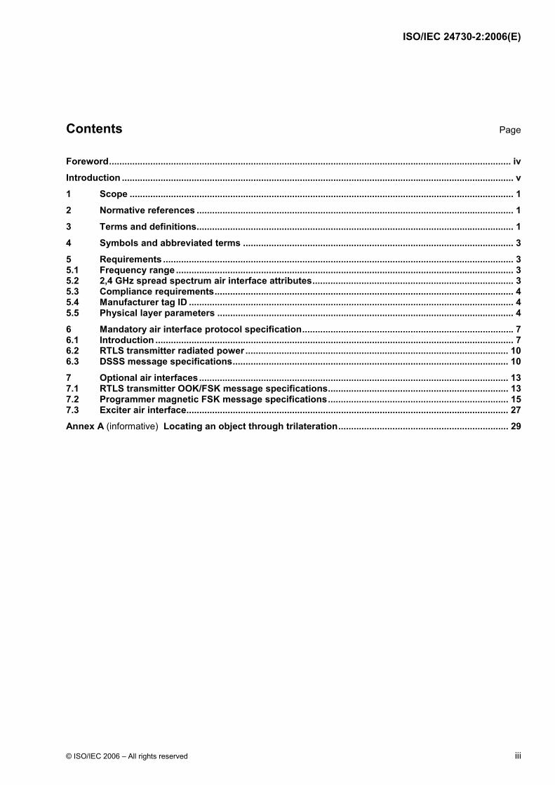
3.5 real-time locating system set of radio frequency receivers and associated computing equipment used to determine the position of a transmitting device relative to the placement of the aforementioned receivers that is capable of reporting that position within several minutes of the transmission used for determining the position of the transmission
Note: Refer to Figure 1 for clarity regarding elements of RTLS infrastructure.
exciter
RTLStransmitters
RTLSinfrastructure
RTLStransmitters
RTLStransmitters
RTLSserver
optionalair
interface
mandatoryair
interface
ApplicationProgramInterface
hostapplications
Figure 1 — Elements of RTLS infrastructure
3.6 RTLS server computing device that aggregates data from the readers and determines location of transmitters
3.7 RTLS transmitter battery powered radio devices that utilize the protocols specified in ISO/IEC 24730
3.8 RTLS reader device that receives signals from an RTLS transmitter
BE49B7BBD066671DDBAE9F84BE28946CA9DF9DF2BA9E929378DC6DB9C7E5059464FF4B45A0F85E8B98E153907E03DE94EF30CDCC12FA6F50BA3323A074E163CA3931B7F7732B0AB51371595948E3757AA5E02727CEF3E6C8A365098C03D01663BB19E0DEEA9EB3D8C542CA64DEDFB03EB47A59A78D4BFB30E27F3AA4E3E48ABE0E29445BBE3A515170EEF94D8F0A266ABD3D64A8149D1D38892BBA9FB68D88E5E9ED33B5DB902E246D74B57FC88D2E035B
Ext
ern
e el
ektr
on
isch
e A
usl
eges
telle
-Beu
th-S
NV
sh
op
Sch
wei
zer.
No
rmen
-Ver
ein
igu
ng
ein
Jo
int
Ven
ture
mit
TF
V-K
dN
r.69
5027
8-ID
.22A
CD
6D3D
B9E
8827
C48
2982
DB
5940
737.
4-20
08-0
5-30
10:
35:4
8

ISO/IEC 24730-2:2006(E)
© ISO/IEC 2006 – All rights reserved 3
3.9 open field path from transmitter to receiver is LOS (line of sight)
[ANS T1.523-2001]
3.10 exciter device that transmits a signal that alters the behaviour of an RTLS transmitter
3.11 upconvert change a baseband signal to a higher frequency signal
3.12 tag blink radio frequency transmission(s) from an RTLS transmitter that may consist of one or multiple duplicate messages
3.13 sub-blink message that is transmitted one or multiple times in a “blink”
4 Symbols and abbreviated terms
For the purposes of this document, the symbols and abbreviated terms given in ISO/IEC 19762-1, ISO/IEC 19762-3 and the following apply.
DSSS Direct Sequence Spread Spectrum
EB Event Blink
EXB EXciter Blink
RTLS Real Time Locating System
TIB Timed Interval Blink
5 Requirements
5.1 Frequency range
This part of ISO/IEC 24730 addresses real-time locating systems (RTLS) operating in the 2,400 GHz to 2,4835 GHz frequencies.
5.2 2,4 GHz spread spectrum air interface attributes
The minimum feature set shall include the following.
⎯ RTLS transmitters shall autonomously generate a direct sequence spread spectrum radio frequency beacon.
⎯ Transmission shall be at a power level that can facilitate reception at ranges of 300 m open-field separation between the transmitter and receiver when operating within the parameters described in Table 1.
BE49B7BBD066671DDBAE9F84BE28946CA9DF9DF2BA9E929378DC6DB9C7E5059464FF4B45A0F85E8B98E153907E03DE94EF30CDCC12FA6F50BA3323A074E163CA3931B7F7732B0AB51371595948E3757AA5E02727CEF3E6C8A365098C03D01663BB19E0DEEA9EB3D8C542CA64DEDFB03EB47A59A78D4BFB30E27F3AA4E3E48ABE0E29445BBE3A515170EEF94D8F0A266ABD3D64A8149D1D38892BBA9FB68D88E5E9ED33B5DB902E246D74B57FC88D2E035B
Ext
ern
e el
ektr
on
isch
e A
usl
eges
telle
-Beu
th-S
NV
sh
op
Sch
wei
zer.
No
rmen
-Ver
ein
igu
ng
ein
Jo
int
Ven
ture
mit
TF
V-K
dN
r.69
5027
8-ID
.22A
CD
6D3D
B9E
8827
C48
2982
DB
5940
737.
4-20
08-0
5-30
10:
35:4
8
ISO/IEC 24730-2:2006(E)
4 © ISO/IEC 2006 – All rights reserved
⎯ RTLS transmitters shall be fully compliant with local regulatory requirements.
⎯ Class 1 RF transmissions are low power and electro-magnetically compatible with and shall not interfere (not cause any measurable difference in throughput) and co-exist with existing standardized ISO/IEC 8802-11 wireless communication networks. They are also systems that co-exist with ISO/IEC 18000-4, and shall not exceed the maximum power requirements of the local regulatory agencies.
⎯ Class II RF transmissions shall not exceed the maximum power requirements of the local regulatory agencies.
5.3 Compliance requirements
The beacon transmitters specified in this part of ISO/IEC 24730 shall transmit at a power level that can facilitate reception at ranges of at least 300 m LOS separation between the transmitter and receiver. Such RTLS transmitters shall be fully compliant with local radio frequency regulatory requirements. Each receiver shall be capable of receiving and processing data from a minimum of 120 beacon transmissions per second. The nominal location data provided by the RTLS shall be within a 3 m radius of the actual location of the RTLS transmitter. The RF transmissions are low power, compatible with, and shall not interfere with existing standardized ISO/IEC 8802-11 wireless communication networks, and systems compliant with ISO/IEC 18000-4.
To be fully compliant with this part of ISO/IEC 24730, RTLS shall also comply with ISO/IEC 24730-1.
5.4 Manufacturer tag ID
The manufacturer’s tag identification number identifies a particular manufacturer and consists of 16 bits. A manufacturer may have more than one ID number. As reported from the RTLS Server to the API, the first 16 bits are designated for the manufacturer’s identification number. As reported from the Data Link Layer to the API, the remaining 16 bits establish a numbering system made unique by the initial manufacturer ID number. The manufacturer’s identification number is a registration in accordance with ISO/IEC 15963. The 16-bit manufacturer’s identification number shall be assigned in accordance with ISO/IEC 15963, under Allocation Class 16h.
5.5 Physical layer parameters
The parameter definitions given in Table 1 apply. These parameters are referenced by parameter name. These operating parameters are to be defined for the temperature range of –30 degrees Celsius to 50 degrees Celsius.
Table 2 and Table 3 specify the parameters for the optional air interfaces that may be implemented.
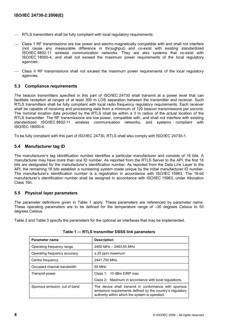
Table 1 — RTLS transmitter DSSS link parameters
Parameter name Description
Operating frequency range 2400 MHz – 2483,50 MHz
Operating frequency accuracy ± 25 ppm maximum
Centre frequency 2441,750 MHz
Occupied channel bandwidth 60 MHz
Transmit power Class 1: 10 dBm EIRP max.
Class 2: Maximum in accordance with local regulations.
Spurious emission, out of band The device shall transmit in conformance with spurious emissions requirements defined by the country’s regulatory authority within which the system is operated.
BE49B7BBD066671DDBAE9F84BE28946CA9DF9DF2BA9E929378DC6DB9C7E5059464FF4B45A0F85E8B98E153907E03DE94EF30CDCC12FA6F50BA3323A074E163CA3931B7F7732B0AB51371595948E3757AA5E02727CEF3E6C8A365098C03D01663BB19E0DEEA9EB3D8C542CA64DEDFB03EB47A59A78D4BFB30E27F3AA4E3E48ABE0E29445BBE3A515170EEF94D8F0A266ABD3D64A8149D1D38892BBA9FB68D88E5E9ED33B5DB902E246D74B57FC88D2E035B
Ext
ern
e el
ektr
on
isch
e A
usl
eges
telle
-Beu
th-S
NV
sh
op
Sch
wei
zer.
No
rmen
-Ver
ein
igu
ng
ein
Jo
int
Ven
ture
mit
TF
V-K
dN
r.69
5027
8-ID
.22A
CD
6D3D
B9E
8827
C48
2982
DB
5940
737.
4-20
08-0
5-30
10:
35:4
8
ISO/IEC 24730-2:2006(E)
© ISO/IEC 2006 – All rights reserved 5
Parameter name Description
Modulation BPSK Direct Sequence Spread Spectrum (DSSS)
Data encoding Differentially encoded
Data bit rate 59,7 kb/s
Bit error rate 0,001%
PN chip rate 30,521875 MHz ± 25 ppm
PN code length 511
PN spread code 0x1CB
Data packet lengths Option 1: 56 bits
Option 2: 72 bits
Option 3: 88 bits
Option 4: 152 bits
Message CRC polynomial G(x)=X12 + X11 + X3 + X2 + X + 1
CRC polynomial initialized value 0x001
Blink interval Programmable, 5 s minimum
Blink interval randomization ± 638 ms maximum
Number of sub-blinks Programmable, 1 - 8
Sub-blink interval randomization 125 ms ± 16 ms maximum
Maximum Frequency Drift < ± 2 ppm over the duration of the entire message
Phase Accuracy < 0,50 radians within any 33 µs period
Phase Noise < 15 degrees when the noise is integrated from 100 Hz to 100 kHz
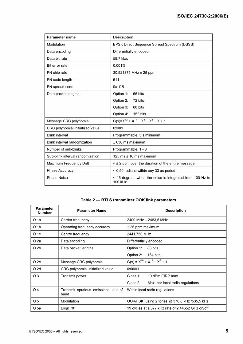
Table 2 — RTLS transmitter OOK link parameters
Parameter Number Parameter Name Description
O 1a Carrier frequency 2400 MHz – 2483,5 MHz
O 1b Operating frequency accuracy ± 25 ppm maximum
O 1c Centre frequency 2441,750 MHz
O 2a Data encoding Differentially encoded
O 2b Data packet lengths Option 1: 88 bits
Option 2: 184 bits
O 2c Message CRC polynomial G(x) = X16 + X12 + X5 + 1
O 2d CRC polynomial initialized value 0x0001
O 3 Transmit power Class 1: 10 dBm EIRP max.
Class 2: Max. per local radio regulations
O 4 Transmit spurious emissions, out of band
Within local radio regulations
O 5 Modulation OOK/FSK, using 2 tones @ 376,8 kHz /535,5 kHz
O 5a Logic “0” 19 cycles at a 377 kHz rate of 2,44652 GHz on/off
BE49B7BBD066671DDBAE9F84BE28946CA9DF9DF2BA9E929378DC6DB9C7E5059464FF4B45A0F85E8B98E153907E03DE94EF30CDCC12FA6F50BA3323A074E163CA3931B7F7732B0AB51371595948E3757AA5E02727CEF3E6C8A365098C03D01663BB19E0DEEA9EB3D8C542CA64DEDFB03EB47A59A78D4BFB30E27F3AA4E3E48ABE0E29445BBE3A515170EEF94D8F0A266ABD3D64A8149D1D38892BBA9FB68D88E5E9ED33B5DB902E246D74B57FC88D2E035B
Ext
ern
e el
ektr
on
isch
e A
usl
eges
telle
-Beu
th-S
NV
sh
op
Sch
wei
zer.
No
rmen
-Ver
ein
igu
ng
ein
Jo
int
Ven
ture
mit
TF
V-K
dN
r.69
5027
8-ID
.22A
CD
6D3D
B9E
8827
C48
2982
DB
5940
737.
4-20
08-0
5-30
10:
35:4
8

ISO/IEC 24730-2:2006(E)
6 © ISO/IEC 2006 – All rights reserved
Parameter Number Parameter Name Description
O 5b Logic “1” 27 cycles at a 535 kHz rate of 2,44652 GHz on/off
O 6 Data rate 19,83 kb/s
O 7 Duty cycle 50%
O 8 Data error rate 0,001% max.
Table 3 — RTLS transmitter magnetic link parameters
Parameter Number Parameter Name Description
M 1 Signalling frequencies 114,688 kHz and 126,976 kHz
M 2 Field strength Regulatory/application dependent
M 3 Bit data rate 2,048 kb/s
M 4 Symbol period 244,14 ms
M 5 Data error rate 0,001%
M 6 Start sync 3 symbol periods @ 114,688 kHz followed by 3 symbol periods @ 126,976 kHz
M 7 End sync 3 symbol periods @ 126,976 kHz followed by 3 symbol periods @ 114,688 kHz
M 8 Data bit 0 1 symbol period @ 126,976 kHz followed by 1 symbol period @ 114,688 kHz
M 9 Data bit 1 1 symbol period @ 114,688 kHz followed by 1 symbol period @ 126,976 kHz
M 10a Programmer packet lengths Option 1: 10 bits
Option 2: 48 bits
Option 3: 64 bits
Option 4: 68 bits
Option 5: 144 bits
Option 6: 160 bits
M 10b Exciter packet lengths Option 1: 10 bits
Option 2: 28 bits
Option 3: 44 bits
Option 4: 144 bits
M 11 Data encoding Manchester encoding
M 12a Programmer message CRC polynomial
G(X) = X12 + X11 + X3 + X2 + X1 + 1
M 12b 28 bit exciter CRC polynomial G(X) = X8 + X4 + X3 + X2 + 1
M 12c 44 bit exciter CRC polynomial G(X) = X12 + X11 + X3 + X2 + X1 + 1
M 12d 10 bit programmer / exciter CRC polynomial
G(X) = X4 + X1 + 1
BE49B7BBD066671DDBAE9F84BE28946CA9DF9DF2BA9E929378DC6DB9C7E5059464FF4B45A0F85E8B98E153907E03DE94EF30CDCC12FA6F50BA3323A074E163CA3931B7F7732B0AB51371595948E3757AA5E02727CEF3E6C8A365098C03D01663BB19E0DEEA9EB3D8C542CA64DEDFB03EB47A59A78D4BFB30E27F3AA4E3E48ABE0E29445BBE3A515170EEF94D8F0A266ABD3D64A8149D1D38892BBA9FB68D88E5E9ED33B5DB902E246D74B57FC88D2E035B
Ext
ern
e el
ektr
on
isch
e A
usl
eges
telle
-Beu
th-S
NV
sh
op
Sch
wei
zer.
No
rmen
-Ver
ein
igu
ng
ein
Jo
int
Ven
ture
mit
TF
V-K
dN
r.69
5027
8-ID
.22A
CD
6D3D
B9E
8827
C48
2982
DB
5940
737.
4-20
08-0
5-30
10:
35:4
8

ISO/IEC 24730-2:2006(E)
© ISO/IEC 2006 – All rights reserved 7
6 Mandatory air interface protocol specification
This part of ISO/IEC 24730 defines the 2,400 GHz to 2,4835 GHz RTLS spread-spectrum transmissions and the command/data level air interface communication protocols. These protocols facilitate communication between a compliant RTLS transmitter and a compliant infrastructure. The optional protocols in clause 7 facilitate communication between an RTLS transmitter and a programming device and also an exciter device respectively. The timing parameters and signal characteristics for the protocols are defined in the physical link specification in clause 5.
6.1 Introduction
Beacon type RTLS system architecture consists of RTLS transmitters that “blink” a Direct Sequence Spread Spectrum (DSSS) signal, and fixed position RTLS readers that receive those signals. The system then determines the x, y location of the RTLS transmitters. Location of tagged assets can be determined with better than 3 m accuracy in most environments, indoors and out. Once the location of the RTLS transmitter is determined, the location information and any other information are passed to the host application.
Additionally, an option that provides the ability to transmit telemetry data is defined.
Functional classification
The RTLS transmitter module is typically a compact internally powered radio frequency device that is a component of the RTLS system. The RTLS system is designed to track and locate items with attached RTLS transmitters. Each locatable transmission is a pulse of direct sequence spread spectrum radio signal. The RTLS infrastructure receives these signals, or blinks. The blink is a short ID-only message or a longer telemetry message also containing the RTLS transmitters ID. Each transmission also contains a status data word that provides information on the RTLS transmitter configuration, battery status and other data. The RTLS transmitter’s ID, status data word, and location are provided to the host by the RTLS Infrastructure. Multiple RTLS transmitters may be present in typical installations allowing a large number of items to be tracked and located in real time.
Anti-collision synchronization protocols are not required. Each “blink” is comprised of multiple sub-blinks. The sub-blinks are part of a multiple level anti-interference system; time diversity, spatial diversity, processing gain. The combination of these multiple sub-blinks, multiple receiving antennas and spread spectrum correlation also allow multiple RTLS transmitters to blink simultaneously and still be received.
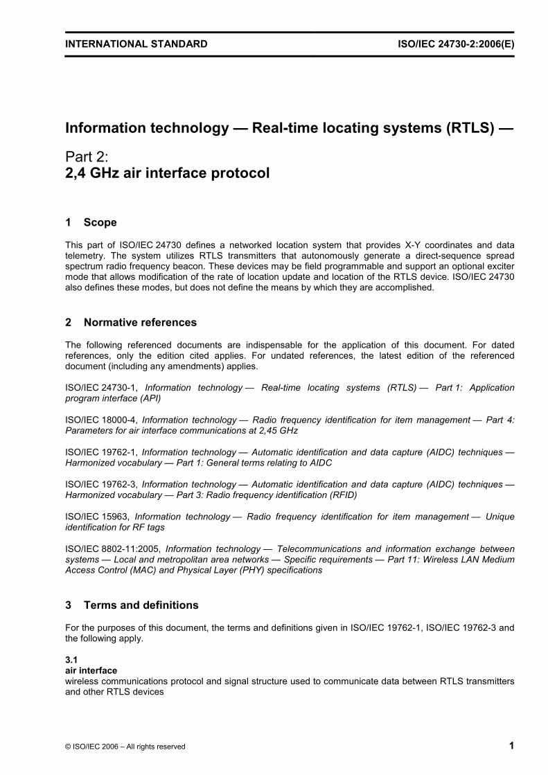
The RTLS transmitter data shall be binary encoded with the MSB (Most Significant Bit) transmitted first in all messages. It is differentially encoded using the example circuit of Figure 2. The output of the encoder shall be initialized to "1". It shall be exclusively OR’d with the output of the PN (Pseudo Noise) generator, modulated using a BPSK (Bi-Phase Shift Keyed) format and upconverted using a single sideband upconverter. The signal is then amplified and transmitted to the RTLS infrastructure.
Figure 2 — Example of differential encoding circuit
An example of the RTLS transmitter PN Generator is shown in Figure 3.
Q
QSET
CLR
DData In
Data Out
Clock
BE49B7BBD066671DDBAE9F84BE28946CA9DF9DF2BA9E929378DC6DB9C7E5059464FF4B45A0F85E8B98E153907E03DE94EF30CDCC12FA6F50BA3323A074E163CA3931B7F7732B0AB51371595948E3757AA5E02727CEF3E6C8A365098C03D01663BB19E0DEEA9EB3D8C542CA64DEDFB03EB47A59A78D4BFB30E27F3AA4E3E48ABE0E29445BBE3A515170EEF94D8F0A266ABD3D64A8149D1D38892BBA9FB68D88E5E9ED33B5DB902E246D74B57FC88D2E035B
Ext
ern
e el
ektr
on
isch
e A
usl
eges
telle
-Beu
th-S
NV
sh
op
Sch
wei
zer.
No
rmen
-Ver
ein
igu
ng
ein
Jo
int
Ven
ture
mit
TF
V-K
dN
r.69
5027
8-ID
.22A
CD
6D3D
B9E
8827
C48
2982
DB
5940
737.
4-20
08-0
5-30
10:
35:4
8
ISO/IEC 24730-2:2006(E)
8 © ISO/IEC 2006 – All rights reserved
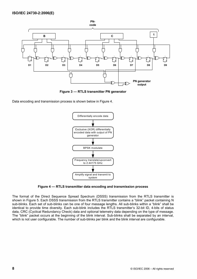
Figure 3 — RTLS transmitter PN generator
Data encoding and transmission process is shown below in Figure 4.
Figure 4 — RTLS transmitter data encoding and transmission process
The format of the Direct Sequence Spread Spectrum (DSSS) transmission from the RTLS transmitter is shown in Figure 5. Each DSSS transmission from the RTLS transmitter contains a “blink” packet containing N sub-blinks. Each set of sub-blinks can be one of four message lengths. All sub-blinks within a “blink” shall be identical to provide time diversity. Each sub-blink includes the RTLS transmitter’s 32-bit ID, 4-bits of status data, CRC (Cyclical Redundancy Check) data and optional telemetry data depending on the type of message. The “blink” packet occurs at the beginning of the blink interval. Sub-blinks shall be separated by an interval, which is not user configurable. The number of sub-blinks per blink and the blink interval are configurable.
Q
Q
SET
CLR
D
Q
Q
SET
CLR
D
Q
Q
SET
CLR
D
Q
Q
SET
CLR
D
Q
Q
SET
CLR
D
Q
Q
SET
CLR
D
Q
Q
SET
CLR
D
Q
Q
SET
CLR
D
Q
Q
SET
CLR
D
CB
PN-code
1
PN generatoroutput
D1 D2 D3 D4 D5 D6 D7 D8 D9
Differentially encode data
Exclusive (XOR) differentiallyencoded data with output of PN
generator
BPSK modulate
Frequency translate/upconvertto 2.44175 GHz
Amplify signal and transmit tosystem
BE49B7BBD066671DDBAE9F84BE28946CA9DF9DF2BA9E929378DC6DB9C7E5059464FF4B45A0F85E8B98E153907E03DE94EF30CDCC12FA6F50BA3323A074E163CA3931B7F7732B0AB51371595948E3757AA5E02727CEF3E6C8A365098C03D01663BB19E0DEEA9EB3D8C542CA64DEDFB03EB47A59A78D4BFB30E27F3AA4E3E48ABE0E29445BBE3A515170EEF94D8F0A266ABD3D64A8149D1D38892BBA9FB68D88E5E9ED33B5DB902E246D74B57FC88D2E035B
Ext
ern
e el
ektr
on
isch
e A
usl
eges
telle
-Beu
th-S
NV
sh
op
Sch
wei
zer.
No
rmen
-Ver
ein
igu
ng
ein
Jo
int
Ven
ture
mit
TF
V-K
dN
r.69
5027
8-ID
.22A
CD
6D3D
B9E
8827
C48
2982
DB
5940
737.
4-20
08-0
5-30
10:
35:4
8
ISO/IEC 24730-2:2006(E)
© ISO/IEC 2006 – All rights reserved 9
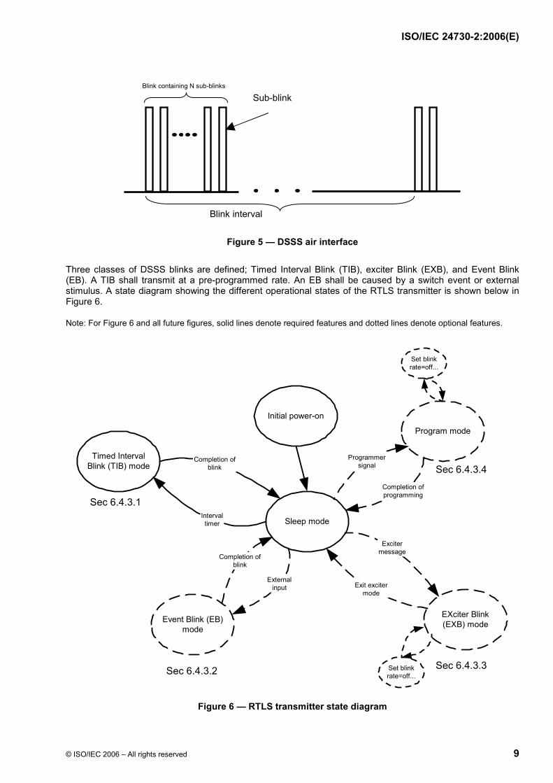
Figure 5 — DSSS air interface
Three classes of DSSS blinks are defined; Timed Interval Blink (TIB), exciter Blink (EXB), and Event Blink (EB). A TIB shall transmit at a pre-programmed rate. An EB shall be caused by a switch event or external stimulus. A state diagram showing the different operational states of the RTLS transmitter is shown below in Figure 6.
Note: For Figure 6 and all future figures, solid lines denote required features and dotted lines denote optional features.
Figure 6 — RTLS transmitter state diagram
Blink interval
Blink containing N sub-blinks
Sub-blink
Sleep mode
Event Blink (EB)mode
EXciter Blink(EXB) mode
Program mode
Timed IntervalBlink (TIB) mode
Completion ofblink
Intervaltimer
Completion ofblink
Externalinput
Programmersignal
Completion ofprogramming
Excitermessage
Exit excitermode
Sec 6.4.3.1
Initial power-on
Sec 6.4.3.2 Sec 6.4.3.3
Sec 6.4.3.4
Set blinkrate=off...
Set blinkrate=off...
BE49B7BBD066671DDBAE9F84BE28946CA9DF9DF2BA9E929378DC6DB9C7E5059464FF4B45A0F85E8B98E153907E03DE94EF30CDCC12FA6F50BA3323A074E163CA3931B7F7732B0AB51371595948E3757AA5E02727CEF3E6C8A365098C03D01663BB19E0DEEA9EB3D8C542CA64DEDFB03EB47A59A78D4BFB30E27F3AA4E3E48ABE0E29445BBE3A515170EEF94D8F0A266ABD3D64A8149D1D38892BBA9FB68D88E5E9ED33B5DB902E246D74B57FC88D2E035B
Ext
ern
e el
ektr
on
isch
e A
usl
eges
telle
-Beu
th-S
NV
sh
op
Sch
wei
zer.
No
rmen
-Ver
ein
igu
ng
ein
Jo
int
Ven
ture
mit
TF
V-K
dN
r.69
5027
8-ID
.22A
CD
6D3D
B9E
8827
C48
2982
DB
5940
737.
4-20
08-0
5-30
10:
35:4
8

ISO/IEC 24730-2:2006(E)
10 © ISO/IEC 2006 – All rights reserved
The DSSS carrier frequency is fixed at 2441,75 MHz and the chip rate shall be fixed at 30,521875 MHz.
6.2 RTLS transmitter radiated power
Two classes of RTLS transmitters exist with respect to the output power level they are capable of delivering. The Equivalent Isotropically Radiated Power (EIRP) of a Class 1 RTLS transmitter is less than 10 mW (10 dBm). Class 1 RTLS transmitters are intended for applications with moderate to dense infrastructures and minimal obstructions.
The EIRP of a Class 2 RTLS transmitter is greater than 10 mW (10 dBm) and less than the maximum allowed by local radio regulations. Class 2 RTLS transmitters are intended for sparse infrastructures where RTLS readers may be located greater than 300 m from the RTLS transmitter or environments with major obstructions.
The antenna of the RTLS transmitter should provide a pattern that is as omni-directional as possible within the constraints of the RTLS transmitter packaging requirements. This will ensure near equivalence with regard to orientation performance of individual transmitters within the system. The RF EIRP of a tag shall not vary more than 10 dB peak to peak in a spherical pattern in free space. It shall not vary more than 10 dB in a semi-spherical pattern around a tag mounted directly to a metallic plate of one square meter in order to achieve the required system performance.
6.3 DSSS message specifications
6.3.1 DSSS message encoding
The PN Spreading Code shall be 0x1CB. The PN Generator is initialized with a “1” in register D9 and “0”’s in all other registers.
The beginning of the blink interval shall be randomized by a maximum of ± 638 ms to avoid repeatedly colliding with blinks from other RTLS transmitters. The beginning of each successive sub-blink shall also be randomized. The interval between each sub-blink shall be 125 ms randomized by a maximum of ± 16 ms from the beginning of the previous sub-blink.
6.3.2 DSSS message structures
There are four different message formats determined by the length of the message in bits: the 56-bit message, the 72-bit message, the 88-bit message, and the 152-bit message. An RTLS transmitter shall be capable of transmitting at least one of these message formats. The 56-bit and 72-bit message format is intended for transmitting the RTLS transmitter ID, the 72- and 88-bit messages are intended for transmitting the RTLS transmitter ID and exciter information and the 152-bit message format is intended for transmitting limited amounts of telemetry information. The structure of each of these message formats is shown in more detail in the following sections.
Each message type contains an 8-bit preamble of 0x01.
Each message type contains a 4-bit RTLS transmitter Status as defined in the message definitions.
72- and 88-bit messages may carry an exciter ID. An exciter ID is comprised of 16 bits. The MSB designates whether the RTLS transmitter has entered or left an exciter field.
Each message type contains a CRC generator polynomial defined by X 12 + X11 + X3 + X2 + X + 1. The preamble is not included in this polynomial.
Each message contains a 32-bit RTLS transmitter ID. These ID’s are defined in the range 1 to 4 294 967 296 (0x00000001 to 0xFFFFFFFF).
Unique data to the each message type is shown.
BE49B7BBD066671DDBAE9F84BE28946CA9DF9DF2BA9E929378DC6DB9C7E5059464FF4B45A0F85E8B98E153907E03DE94EF30CDCC12FA6F50BA3323A074E163CA3931B7F7732B0AB51371595948E3757AA5E02727CEF3E6C8A365098C03D01663BB19E0DEEA9EB3D8C542CA64DEDFB03EB47A59A78D4BFB30E27F3AA4E3E48ABE0E29445BBE3A515170EEF94D8F0A266ABD3D64A8149D1D38892BBA9FB68D88E5E9ED33B5DB902E246D74B57FC88D2E035B
Ext
ern
e el
ektr
on
isch
e A
usl
eges
telle
-Beu
th-S
NV
sh
op
Sch
wei
zer.
No
rmen
-Ver
ein
igu
ng
ein
Jo
int
Ven
ture
mit
TF
V-K
dN
r.69
5027
8-ID
.22A
CD
6D3D
B9E
8827
C48
2982
DB
5940
737.
4-20
08-0
5-30
10:
35:4
8

ISO/IEC 24730-2:2006(E)
© ISO/IEC 2006 – All rights reserved 11
6.3.2.1 DSSS 56-bit message format
The DSSS 56-bit message format for the RTLS transmitter is shown in Table 4. The 56-bit message format consists of the 8-bit preamble, the 4-bit RTLS transmitter status field, a 32-bit field containing the RTLS transmitter ID and the 12-bit CRC field for a total message length of 56 bits. The 56-bit message shall have a transmission duration of 937,5 µs.
Table 4 — DSSS 56-bit message formats
Preamble RTLS transmitter status RTLS transmitter ID CRC
8 "0" S2 S1 B 32 12
8 "1" Reserved 32 12
Bit 55 to bit 48 Bit 47 to bit 44 Bit 43 to bit 12 Bit 11 to bit 0
For S1 and S2 a value of "1" shall equal a set condition. For B, (the battery bit), a value of "1" shall equal a notification of a battery alarm.
6.3.2.2 DSSS 72-bit message format
The DSSS 72-bit message format for the RTLS transmitter is shown in Table 5. The 72-bit message format consists of the 8-bit preamble, the 4-bit RTLS transmitter status field, a 32-bit field containing the RTLS transmitter ID, a 16-bit payload field, and the 12-bit CRC field for a total message length of 72 bits. The 72-bit message can be used for communicating the RTLS transmitter’s 32-bit ID and either data or an exciter address or an extended RTLS transmitter ID as payload. The status field determines the content format of the payload field. The 72-bit message shall have a transmission duration of 1,205 ms.
Table 5 — DSSS 72-bit message format
Preamble RTLS transmitter status
RTLS transmitter ID Payload CRC
8 "0" S2 S1 B 32 Extended ID 12
8 "1" "0" "0" "0" 32 Exciter ID 12
8 "1" X X X 32 Indexed Data 12
Bit 71 to bit 64 Bit 63 to bit 60 Bit 59 to bit 28 Bit 27 to bit 12 Bit11 to bit 0
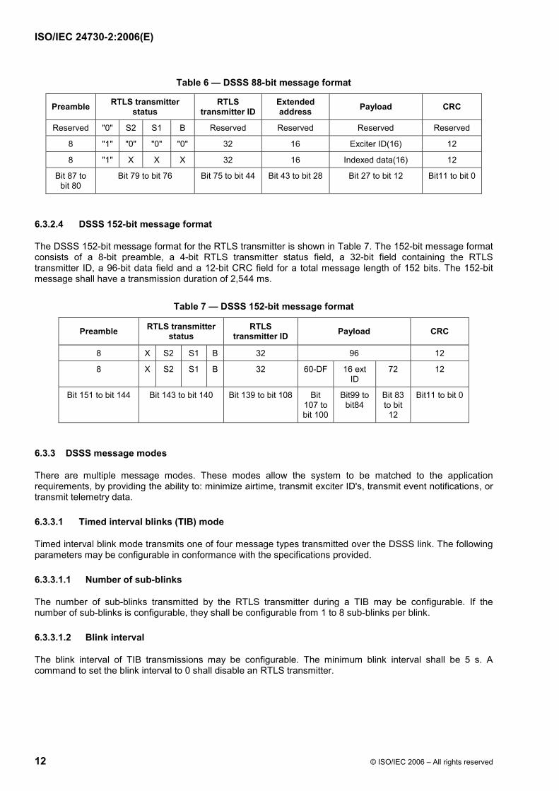
6.3.2.3 DSSS 88-bit message format
The DSSS 88-bit message format for the RTLS transmitter is shown in Table 6. The 88-bit message format consists of a 8-bit preamble, a 4-bit RTLS transmitter status field, a 32-bit field containing the RTLS transmitter ID, a 16-bit exciter field, an additional 16-bit address field, and a 12-bit CRC field for a total message length of 88 bits. The 88-bit message format can be used for communicating the RTLS transmitter’s 32-bit ID and an extended RTLS transmitter ID and either an exciter address or data as the payload. The status field determines the content format of the payload field. The 88-bit message shall have a transmission duration of 1,473 ms.
BE49B7BBD066671DDBAE9F84BE28946CA9DF9DF2BA9E929378DC6DB9C7E5059464FF4B45A0F85E8B98E153907E03DE94EF30CDCC12FA6F50BA3323A074E163CA3931B7F7732B0AB51371595948E3757AA5E02727CEF3E6C8A365098C03D01663BB19E0DEEA9EB3D8C542CA64DEDFB03EB47A59A78D4BFB30E27F3AA4E3E48ABE0E29445BBE3A515170EEF94D8F0A266ABD3D64A8149D1D38892BBA9FB68D88E5E9ED33B5DB902E246D74B57FC88D2E035B
Ext
ern
e el
ektr
on
isch
e A
usl
eges
telle
-Beu
th-S
NV
sh
op
Sch
wei
zer.
No
rmen
-Ver
ein
igu
ng
ein
Jo
int
Ven
ture
mit
TF
V-K
dN
r.69
5027
8-ID
.22A
CD
6D3D
B9E
8827
C48
2982
DB
5940
737.
4-20
08-0
5-30
10:
35:4
8
ISO/IEC 24730-2:2006(E)
12 © ISO/IEC 2006 – All rights reserved
Table 6 — DSSS 88-bit message format
Preamble RTLS transmitter status
RTLS transmitter ID
Extended address Payload CRC
Reserved "0" S2 S1 B Reserved Reserved Reserved Reserved
8 "1" "0" "0" "0" 32 16 Exciter ID(16) 12
8 "1" X X X 32 16 Indexed data(16) 12
Bit 87 to bit 80
Bit 79 to bit 76 Bit 75 to bit 44 Bit 43 to bit 28 Bit 27 to bit 12 Bit11 to bit 0
6.3.2.4 DSSS 152-bit message format
The DSSS 152-bit message format for the RTLS transmitter is shown in Table 7. The 152-bit message format consists of a 8-bit preamble, a 4-bit RTLS transmitter status field, a 32-bit field containing the RTLS transmitter ID, a 96-bit data field and a 12-bit CRC field for a total message length of 152 bits. The 152-bit message shall have a transmission duration of 2,544 ms.
Table 7 — DSSS 152-bit message format
Preamble RTLS transmitter status
RTLS transmitter ID Payload CRC
8 X S2 S1 B 32 96 12
8 X S2 S1 B 32 60-DF 16 ext ID
72 12
Bit 151 to bit 144 Bit 143 to bit 140 Bit 139 to bit 108 Bit 107 to bit 100
Bit99 to bit84
Bit 83 to bit 12
Bit11 to bit 0
6.3.3 DSSS message modes
There are multiple message modes. These modes allow the system to be matched to the application requirements, by providing the ability to: minimize airtime, transmit exciter ID's, transmit event notifications, or transmit telemetry data.
6.3.3.1 Timed interval blinks (TIB) mode
Timed interval blink mode transmits one of four message types transmitted over the DSSS link. The following parameters may be configurable in conformance with the specifications provided.
6.3.3.1.1 Number of sub-blinks
The number of sub-blinks transmitted by the RTLS transmitter during a TIB may be configurable. If the number of sub-blinks is configurable, they shall be configurable from 1 to 8 sub-blinks per blink.
6.3.3.1.2 Blink interval
The blink interval of TIB transmissions may be configurable. The minimum blink interval shall be 5 s. A command to set the blink interval to 0 shall disable an RTLS transmitter.
BE49B7BBD066671DDBAE9F84BE28946CA9DF9DF2BA9E929378DC6DB9C7E5059464FF4B45A0F85E8B98E153907E03DE94EF30CDCC12FA6F50BA3323A074E163CA3931B7F7732B0AB51371595948E3757AA5E02727CEF3E6C8A365098C03D01663BB19E0DEEA9EB3D8C542CA64DEDFB03EB47A59A78D4BFB30E27F3AA4E3E48ABE0E29445BBE3A515170EEF94D8F0A266ABD3D64A8149D1D38892BBA9FB68D88E5E9ED33B5DB902E246D74B57FC88D2E035B
Ext
ern
e el
ektr
on
isch
e A
usl
eges
telle
-Beu
th-S
NV
sh
op
Sch
wei
zer.
No
rmen
-Ver
ein
igu
ng
ein
Jo
int
Ven
ture
mit
TF
V-K
dN
r.69
5027
8-ID
.22A
CD
6D3D
B9E
8827
C48
2982
DB
5940
737.
4-20
08-0
5-30
10:
35:4
8
ISO/IEC 24730-2:2006(E)
© ISO/IEC 2006 – All rights reserved 13
6.3.3.1.3 152-bit blink repetition rate
The 152-bit blink repetition rate shall define the TIB repetition rate for 152-bit messages. Available intervals shall be every 8th blink, every 64th blink, always or never.
6.3.3.2 Event blink (EB) mode
Events are defined as pushbutton activation, slide switch toggles, or other external inputs. Event blinks shall occur only after an event is detected. After an event is detected, the RTLS transmitter shall blink from 1 to 15 times as programmed. The minimum blink interval shall be 5 seconds. An EB shall be 56, 72, or 152 bits in length.
If the transmitter is disabled an event shall not cause a blink.
6.3.3.2.1 Number of event blinks
The number of EBs for the RTLS transmitter should be configurable from 0 to 15 blinks per event.
6.3.3.2.2 Event blink interval
The Event Blink Interval shall be 5 s or greater.
6.3.3.2.3 Event blink re-trigger time
The Event Blink Re-trigger Interval is defined as the time to ignore the same event input after the last blink. The Event Blink Re-trigger Interval period shall be 5 s or greater.
6.3.3.3 Exciter blink (EXB) mode
If supported, exciter Blink Mode allow the system to modify the RTLS transmitter blink rate to provide a different blink rate or a finer level of location by providing a locate function with regard to then exciter.
6.3.3.4 Program mode
If supported, Program Mode allows an RTLS transmitter to have operational parameters programmed. The RTLS transmitter may also be turned on and off in this mode.
7 Optional air interfaces
The RTLS transmitter may support the use of a programmer and an exciter. If the RTLS transmitter does support the use of these devices, then it shall comply with the following clauses.
7.1 RTLS transmitter OOK/FSK message specifications
If the RTLS transmitter does support the use of a programmer, then it shall respond to the programmer with OOK/FSK messages as defined below.
7.1.1 OOK/FSK blink message description
The RTLS transmitter may include a method to respond to a programming device.
If the RTLS transmitter includes this capability, the transmitter shall receive commands transmitted using Magnetic FSK and use OOK/FSK (On-Off-Keyed (OOK)/Frequency Shift Keyed (FSK)) transmissions to respond to the programming device. The programming device may be used to write and read configuration information, load data registers, and/or read the identity from the RTLS transmitter.
BE49B7BBD066671DDBAE9F84BE28946CA9DF9DF2BA9E929378DC6DB9C7E5059464FF4B45A0F85E8B98E153907E03DE94EF30CDCC12FA6F50BA3323A074E163CA3931B7F7732B0AB51371595948E3757AA5E02727CEF3E6C8A365098C03D01663BB19E0DEEA9EB3D8C542CA64DEDFB03EB47A59A78D4BFB30E27F3AA4E3E48ABE0E29445BBE3A515170EEF94D8F0A266ABD3D64A8149D1D38892BBA9FB68D88E5E9ED33B5DB902E246D74B57FC88D2E035B
Ext
ern
e el
ektr
on
isch
e A
usl
eges
telle
-Beu
th-S
NV
sh
op
Sch
wei
zer.
No
rmen
-Ver
ein
igu
ng
ein
Jo
int
Ven
ture
mit
TF
V-K
dN
r.69
5027
8-ID
.22A
CD
6D3D
B9E
8827
C48
2982
DB
5940
737.
4-20
08-0
5-30
10:
35:4
8

ISO/IEC 24730-2:2006(E)
14 © ISO/IEC 2006 – All rights reserved
If external programming and/or data load is supported, there shall be two different message lengths, 88-bit and 184-bit. The structure of the 88-bit message shall include a 24-bit preamble, 8-bit status field, 32-bit tag ID, 8-bit ACK, 16-bit CRC. The structure of the 184-bit message shall add 96-bits of data between the ACK and the CRC.
The data transmitted shall be differentially encoded and start with logic “0”. The FSK rate shall correspond to the differential data with 376.8 kHz representing logic “0”, and 535,5 kHz representing logic “1”. Each bit period shall be 50,423 ms.
7.1.2 OOK/FSK message encodation
A logical “0” shall be represented by 19 cycles at a 377 kHz rate of 2,44652 GHz RF signal. A logical “1” shall be represented by 27 cycles at a 535 kHz rate of 2,44652 GHz RF signal. The OOK/FSK message encodation is shown in Figure 7 below.
Figure 7 — OOK/FSK message encodation
7.1.3 OOK/FSK message formats
Table 8 shows the message structure that shall be used for an 88-bit OOK/FSK message.
Table 8 — OOK/FSK 88-bit message structure
Bits Field length Description
87 to 64 24-bit Preamble = 0x00F7BC
63 to 56 8-bit Tag Status (=0000+the RTLS transmitter’s last status sent via a DSSS message)
55 to 24 32-bit Tag ID
23 to 16 8-bit ACK, G(x) = x8 + x4 + x3 + x2 + 1 in response to magnetic messages of 28 bits or more
ACK shall be 0x00 in response to magnetic messages of less than 28 bits
15 to 0 16-bit Message CRC: G(x) = x16 + x12 + x5 + 1
Logic "0" Logic "1"
19 clock cycles of 377kHz
27 clock cycles of 535 kHz
2.4 GHz Carrier Signal
DATA
535 kHzClock
377 kHzClock
2.4 GHzCarrier
OOK/FSKOutput
BE49B7BBD066671DDBAE9F84BE28946CA9DF9DF2BA9E929378DC6DB9C7E5059464FF4B45A0F85E8B98E153907E03DE94EF30CDCC12FA6F50BA3323A074E163CA3931B7F7732B0AB51371595948E3757AA5E02727CEF3E6C8A365098C03D01663BB19E0DEEA9EB3D8C542CA64DEDFB03EB47A59A78D4BFB30E27F3AA4E3E48ABE0E29445BBE3A515170EEF94D8F0A266ABD3D64A8149D1D38892BBA9FB68D88E5E9ED33B5DB902E246D74B57FC88D2E035B
Ext
ern
e el
ektr
on
isch
e A
usl
eges
telle
-Beu
th-S
NV
sh
op
Sch
wei
zer.
No
rmen
-Ver
ein
igu
ng
ein
Jo
int
Ven
ture
mit
TF
V-K
dN
r.69
5027
8-ID
.22A
CD
6D3D
B9E
8827
C48
2982
DB
5940
737.
4-20
08-0
5-30
10:
35:4
8
ISO/IEC 24730-2:2006(E)
© ISO/IEC 2006 – All rights reserved 15
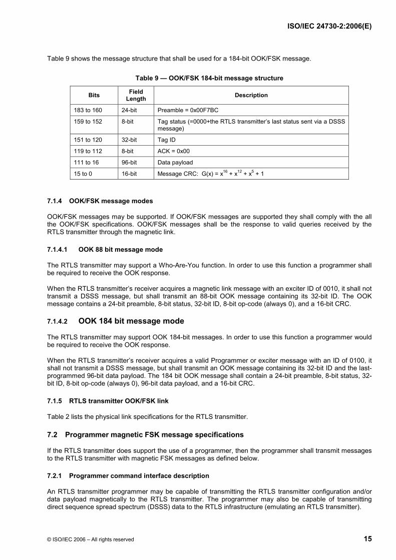
Table 9 shows the message structure that shall be used for a 184-bit OOK/FSK message.
Table 9 — OOK/FSK 184-bit message structure
Bits Field Length Description
183 to 160 24-bit Preamble = 0x00F7BC
159 to 152 8-bit Tag status (=0000+the RTLS transmitter’s last status sent via a DSSS message)
151 to 120 32-bit Tag ID
119 to 112 8-bit ACK = 0x00
111 to 16 96-bit Data payload
15 to 0 16-bit Message CRC: G(x) = x16 + x12 + x5 + 1
7.1.4 OOK/FSK message modes
OOK/FSK messages may be supported. If OOK/FSK messages are supported they shall comply with the all the OOK/FSK specifications. OOK/FSK messages shall be the response to valid queries received by the RTLS transmitter through the magnetic link.
7.1.4.1 OOK 88 bit message mode
The RTLS transmitter may support a Who-Are-You function. In order to use this function a programmer shall be required to receive the OOK response.
When the RTLS transmitter’s receiver acquires a magnetic link message with an exciter ID of 0010, it shall not transmit a DSSS message, but shall transmit an 88-bit OOK message containing its 32-bit ID. The OOK message contains a 24-bit preamble, 8-bit status, 32-bit ID, 8-bit op-code (always 0), and a 16-bit CRC.
7.1.4.2 OOK 184 bit message mode
The RTLS transmitter may support OOK 184-bit messages. In order to use this function a programmer would be required to receive the OOK response.
When the RTLS transmitter’s receiver acquires a valid Programmer or exciter message with an ID of 0100, it shall not transmit a DSSS message, but shall transmit an OOK message containing its 32-bit ID and the last-programmed 96-bit data payload. The 184 bit OOK message shall contain a 24-bit preamble, 8-bit status, 32-bit ID, 8-bit op-code (always 0), 96-bit data payload, and a 16-bit CRC.
7.1.5 RTLS transmitter OOK/FSK link
Table 2 lists the physical link specifications for the RTLS transmitter.
7.2 Programmer magnetic FSK message specifications
If the RTLS transmitter does support the use of a programmer, then the programmer shall transmit messages to the RTLS transmitter with magnetic FSK messages as defined below.
7.2.1 Programmer command interface description
An RTLS transmitter programmer may be capable of transmitting the RTLS transmitter configuration and/or data payload magnetically to the RTLS transmitter. The programmer may also be capable of transmitting direct sequence spread spectrum (DSSS) data to the RTLS infrastructure (emulating an RTLS transmitter).
BE49B7BBD066671DDBAE9F84BE28946CA9DF9DF2BA9E929378DC6DB9C7E5059464FF4B45A0F85E8B98E153907E03DE94EF30CDCC12FA6F50BA3323A074E163CA3931B7F7732B0AB51371595948E3757AA5E02727CEF3E6C8A365098C03D01663BB19E0DEEA9EB3D8C542CA64DEDFB03EB47A59A78D4BFB30E27F3AA4E3E48ABE0E29445BBE3A515170EEF94D8F0A266ABD3D64A8149D1D38892BBA9FB68D88E5E9ED33B5DB902E246D74B57FC88D2E035B
Ext
ern
e el
ektr
on
isch
e A
usl
eges
telle
-Beu
th-S
NV
sh
op
Sch
wei
zer.
No
rmen
-Ver
ein
igu
ng
ein
Jo
int
Ven
ture
mit
TF
V-K
dN
r.69
5027
8-ID
.22A
CD
6D3D
B9E
8827
C48
2982
DB
5940
737.
4-20
08-0
5-30
10:
35:4
8

ISO/IEC 24730-2:2006(E)
16 © ISO/IEC 2006 – All rights reserved
If used, the interface from the programmer to the RTLS transmitter shall be via an FSK magnetic signal using Manchester Encoding. The response from the RTLS transmitter to the programmer for acknowledgements shall be via the previously defined OOK/FSK RF signal as defined in 6.5.1.3
7.2.2 Programmer configuration message protocol
The programmer configuration message is used to set the transmitters configurable parameters and operating modes.
The message exchange between the programmer and the RTLS transmitter shall be as shown in Figure 8.
Figure 8 — Write configuration message exchange
The programmer configuration message shall consist of a 160-bit magnetic message containing
• 4-bit op-code (1010), • 32-bit RTLS transmitter ID, • 112-bit RTLS transmitter configuration, • 12-bit message CRC.
The 160-bit configuration message is preceded by 200 ms of an alternating “1” and “0” signal at the symbol rate defined in 6.5.1.2. This signal shall cause the magnetic receiver to stay active until the message is received. The configuration message from the programmer to the RTLS transmitter shall be Manchester Coded. The format of the 160-bit configuration message is shown in Table 10.
Txconfiguration
Rxconfiguration
Tx Ack1
Rx ack1
Tx load
88 bits OOK
Rx load
Tx ack2=00
10 bits magnetic
Rx ack2
88 bits OOK
160 bits magnetic
Programmer RTLStransmitter
BE49B7BBD066671DDBAE9F84BE28946CA9DF9DF2BA9E929378DC6DB9C7E5059464FF4B45A0F85E8B98E153907E03DE94EF30CDCC12FA6F50BA3323A074E163CA3931B7F7732B0AB51371595948E3757AA5E02727CEF3E6C8A365098C03D01663BB19E0DEEA9EB3D8C542CA64DEDFB03EB47A59A78D4BFB30E27F3AA4E3E48ABE0E29445BBE3A515170EEF94D8F0A266ABD3D64A8149D1D38892BBA9FB68D88E5E9ED33B5DB902E246D74B57FC88D2E035B
Ext
ern
e el
ektr
on
isch
e A
usl
eges
telle
-Beu
th-S
NV
sh
op
Sch
wei
zer.
No
rmen
-Ver
ein
igu
ng
ein
Jo
int
Ven
ture
mit
TF
V-K
dN
r.69
5027
8-ID
.22A
CD
6D3D
B9E
8827
C48
2982
DB
5940
737.
4-20
08-0
5-30
10:
35:4
8

ISO/IEC 24730-2:2006(E)
© ISO/IEC 2006 – All rights reserved 17
Table 10 — Programmer configuration message format (160-bits)
Bits Description
159 to 156 Op-code = "1010"
155 to 124 Message id = RTLS transmitter ID
123 to 92 RTLS transmitter id, id RTLS transmitter will assume after configuration
91 to 88 TIB interval
87 to 85 Number of sub-blinks per TIB
84 to 75 DSSS PN code
74 to 72 Reserved = 000
71 Reserved = 0
70 to 67 Number of exciter blinks
66 to 64 Exciter blink interval
63 to 61 Exciter re-trigger mode
60 to 55 Event configuration
54 to 52 Reserved = "000"
51 to 48 Number of event blinks
47 to 45 Event blink interval
44 to 42 Event blink re-trigger time
41 to 40 Reserved = "00"
39 Reserved = "0"
38 to 36 Reserved = "100"
35 to 32 Alternate exciter blink mode interval
31 to 29 Alternate exciter blink mode duration
28 Sib field-dependent re-trigger
27 to 25 Reserved = "011"
24 to 21 Reserved = "0000"
20 Reserved = "0"
19 Rx on interval, 200 ms or 500 ms
18 Reserved = "0"
17 to 16 DSSS long message interval
15 Reserved = "0"
14 Reserved = "0"
13 to 12 Reserved = "00"
11 to 0 Message CRC g (x) = x12 + x11 + x3 + x2 + x1 + 1
The RTLS transmitter shall respond within 1,5 s via OOK/FSK if the programmer’s message meets the following requirements:
• the message is 160 bits, • the message ID matches the RTLS transmitter’s ID, • the op-code field is “1010”, • the 12-bit CRC check passes.
BE49B7BBD066671DDBAE9F84BE28946CA9DF9DF2BA9E929378DC6DB9C7E5059464FF4B45A0F85E8B98E153907E03DE94EF30CDCC12FA6F50BA3323A074E163CA3931B7F7732B0AB51371595948E3757AA5E02727CEF3E6C8A365098C03D01663BB19E0DEEA9EB3D8C542CA64DEDFB03EB47A59A78D4BFB30E27F3AA4E3E48ABE0E29445BBE3A515170EEF94D8F0A266ABD3D64A8149D1D38892BBA9FB68D88E5E9ED33B5DB902E246D74B57FC88D2E035B
Ext
ern
e el
ektr
on
isch
e A
usl
eges
telle
-Beu
th-S
NV
sh
op
Sch
wei
zer.
No
rmen
-Ver
ein
igu
ng
ein
Jo
int
Ven
ture
mit
TF
V-K
dN
r.69
5027
8-ID
.22A
CD
6D3D
B9E
8827
C48
2982
DB
5940
737.
4-20
08-0
5-30
10:
35:4
8
ISO/IEC 24730-2:2006(E)
18 © ISO/IEC 2006 – All rights reserved
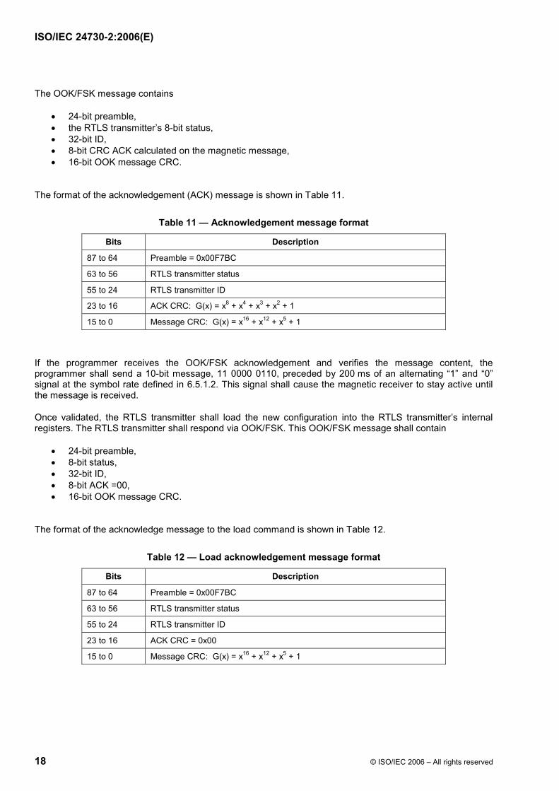
The OOK/FSK message contains
• 24-bit preamble, • the RTLS transmitter’s 8-bit status, • 32-bit ID, • 8-bit CRC ACK calculated on the magnetic message, • 16-bit OOK message CRC.
The format of the acknowledgement (ACK) message is shown in Table 11.
Table 11 — Acknowledgement message format
Bits Description
87 to 64 Preamble = 0x00F7BC
63 to 56 RTLS transmitter status
55 to 24 RTLS transmitter ID
23 to 16 ACK CRC: G(x) = x8 + x4 + x3 + x2 + 1
15 to 0 Message CRC: G(x) = x16 + x12 + x5 + 1
If the programmer receives the OOK/FSK acknowledgement and verifies the message content, the programmer shall send a 10-bit message, 11 0000 0110, preceded by 200 ms of an alternating “1” and “0” signal at the symbol rate defined in 6.5.1.2. This signal shall cause the magnetic receiver to stay active until the message is received.
Once validated, the RTLS transmitter shall load the new configuration into the RTLS transmitter’s internal registers. The RTLS transmitter shall respond via OOK/FSK. This OOK/FSK message shall contain
• 24-bit preamble, • 8-bit status, • 32-bit ID, • 8-bit ACK =00, • 16-bit OOK message CRC.
The format of the acknowledge message to the load command is shown in Table 12.
Table 12 — Load acknowledgement message format
Bits Description
87 to 64 Preamble = 0x00F7BC
63 to 56 RTLS transmitter status
55 to 24 RTLS transmitter ID
23 to 16 ACK CRC = 0x00
15 to 0 Message CRC: G(x) = x16 + x12 + x5 + 1
BE49B7BBD066671DDBAE9F84BE28946CA9DF9DF2BA9E929378DC6DB9C7E5059464FF4B45A0F85E8B98E153907E03DE94EF30CDCC12FA6F50BA3323A074E163CA3931B7F7732B0AB51371595948E3757AA5E02727CEF3E6C8A365098C03D01663BB19E0DEEA9EB3D8C542CA64DEDFB03EB47A59A78D4BFB30E27F3AA4E3E48ABE0E29445BBE3A515170EEF94D8F0A266ABD3D64A8149D1D38892BBA9FB68D88E5E9ED33B5DB902E246D74B57FC88D2E035B
Ext
ern
e el
ektr
on
isch
e A
usl
eges
telle
-Beu
th-S
NV
sh
op
Sch
wei
zer.
No
rmen
-Ver
ein
igu
ng
ein
Jo
int
Ven
ture
mit
TF
V-K
dN
r.69
5027
8-ID
.22A
CD
6D3D
B9E
8827
C48
2982
DB
5940
737.
4-20
08-0
5-30
10:
35:4
8
ISO/IEC 24730-2:2006(E)
© ISO/IEC 2006 – All rights reserved 19
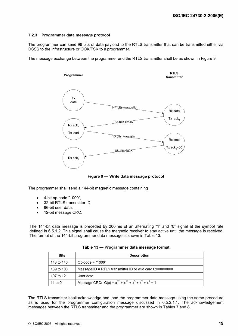
7.2.3 Programmer data message protocol
The programmer can send 96 bits of data payload to the RTLS transmitter that can be transmitted either via DSSS to the infrastructure or OOK/FSK to a programmer.
The message exchange between the programmer and the RTLS transmitter shall be as shown in Figure 9
Figure 9 — Write data message protocol
The programmer shall send a 144-bit magnetic message containing
• 4-bit op-code "1000", • 32-bit RTLS transmitter ID, • 96-bit user data, • 12-bit message CRC.
The 144-bit data message is preceded by 200 ms of an alternating “1” and “0” signal at the symbol rate defined in 6.5.1.2. This signal shall cause the magnetic receiver to stay active until the message is received. The format of the 144-bit programmer data message is shown in Table 13.
Table 13 — Programmer data message format
Bits Description
143 to 140 Op-code = "1000"
139 to 108 Message ID = RTLS transmitter ID or wild card 0x00000000
107 to 12 User data
11 to 0 Message CRC: G(x) = x12 + x11 + x3 + x2 + x1 + 1
The RTLS transmitter shall acknowledge and load the programmer data message using the same procedure as is used for the programmer configuration message discussed in 6.5.2.1.1. The acknowledgement messages between the RTLS transmitter and the programmer are shown in Tables 7 and 8.
Txdata
Rx data
Tx ack1
Rx ack1
Tx load
88 bits O/OK
Rx load
Tx ack2=00
10 bits magnetic
Rx ack2
88 bits OOK
144 bits magnetic
Programmer RTLStransmitter
BE49B7BBD066671DDBAE9F84BE28946CA9DF9DF2BA9E929378DC6DB9C7E5059464FF4B45A0F85E8B98E153907E03DE94EF30CDCC12FA6F50BA3323A074E163CA3931B7F7732B0AB51371595948E3757AA5E02727CEF3E6C8A365098C03D01663BB19E0DEEA9EB3D8C542CA64DEDFB03EB47A59A78D4BFB30E27F3AA4E3E48ABE0E29445BBE3A515170EEF94D8F0A266ABD3D64A8149D1D38892BBA9FB68D88E5E9ED33B5DB902E246D74B57FC88D2E035B
Ext
ern
e el
ektr
on
isch
e A
usl
eges
telle
-Beu
th-S
NV
sh
op
Sch
wei
zer.
No
rmen
-Ver
ein
igu
ng
ein
Jo
int
Ven
ture
mit
TF
V-K
dN
r.69
5027
8-ID
.22A
CD
6D3D
B9E
8827
C48
2982
DB
5940
737.
4-20
08-0
5-30
10:
35:4
8

ISO/IEC 24730-2:2006(E)
20 © ISO/IEC 2006 – All rights reserved
7.2.4 Write indexed data command (68-bit)
The following commands all cause the RTLS transmitter to respond with DSSS transmission as defined by the EXB portion of 6.4.2.2 through 6.4.2.4.
The message exchange between the programmer and the RTLS transmitter shall be as shown in Figure 10.
Figure 10 — Write indexed data message protocol
The 68-bit data message is preceded by 200 ms of an alternating “1” and “0” signal at the symbol rate defined in 6.5.1.2. This signal shall cause the magnetic receiver to stay active until the message is received.
The type of transmission and the data included shall depend on the op-code of the command. See Table 14 for bit definitions of the magnetic commands. The RTLS transmitter shall respond with an OOK/FSK ACK and DSSS blinks if the message is validated for length, op-code, and CRC. The OOK/FSK ACK response shall be as defined below:
• 24-bit preamble, • 8-bit status, • 32-bit RTLS transmitter ID, • 8-bit CRC ACK calculated on the magnetic message, • 16-bit OOK message CRC.
When the validated message op-code is "1111", the RTLS transmitter shall respond with 152-bit DSSS message blinks following the OOK acknowledge message. The message is defined as follows:
• 8-bit Preamble, • 4-bit RTLS transmitter Status = Defined in command, • 32-bit RTLS transmitter ID, • 8-bit = 0xFE, • 16-bit Data Payload, • last 72-bits of RTLS transmitter 96-bit data register, • 12-bit CRC.
Txindex data
Rx index data
Tx ack
Rx ack
88 bits OOK
68 bits magnetic
Programmer RTLStransmitter
72 or 88 bits Tx DSSS
BE49B7BBD066671DDBAE9F84BE28946CA9DF9DF2BA9E929378DC6DB9C7E5059464FF4B45A0F85E8B98E153907E03DE94EF30CDCC12FA6F50BA3323A074E163CA3931B7F7732B0AB51371595948E3757AA5E02727CEF3E6C8A365098C03D01663BB19E0DEEA9EB3D8C542CA64DEDFB03EB47A59A78D4BFB30E27F3AA4E3E48ABE0E29445BBE3A515170EEF94D8F0A266ABD3D64A8149D1D38892BBA9FB68D88E5E9ED33B5DB902E246D74B57FC88D2E035B
Ext
ern
e el
ektr
on
isch
e A
usl
eges
telle
-Beu
th-S
NV
sh
op
Sch
wei
zer.
No
rmen
-Ver
ein
igu
ng
ein
Jo
int
Ven
ture
mit
TF
V-K
dN
r.69
5027
8-ID
.22A
CD
6D3D
B9E
8827
C48
2982
DB
5940
737.
4-20
08-0
5-30
10:
35:4
8
ISO/IEC 24730-2:2006(E)
© ISO/IEC 2006 – All rights reserved 21
When the validated message op-code is 1101, the RTLS transmitter shall respond with 72/88-bit DSSS message blinks following the OOK acknowledge message. The message is defined as follows:
• 8-bit Preamble, • 4-bit RTLS transmitter Status = Defined in command, • 32-bit RTLS transmitter ID, • *ext ID (only if 88 bit message), • 16-bit Data Payload, • 12-bit CRC.
Table 14 — 68-bit data payload commands
Bits 152-bit Response 72/88-bit Response
67 to 64 Op-code = 1111 Op-code = 1101
63 to 60 RTLS transmitter TX Status RTLS transmitter TX Status
59 to 28 RTLS transmitter ID RTLS transmitter ID
27 to 12 Data Payload Data Payload
11 to 0 Message CRC Message CRC
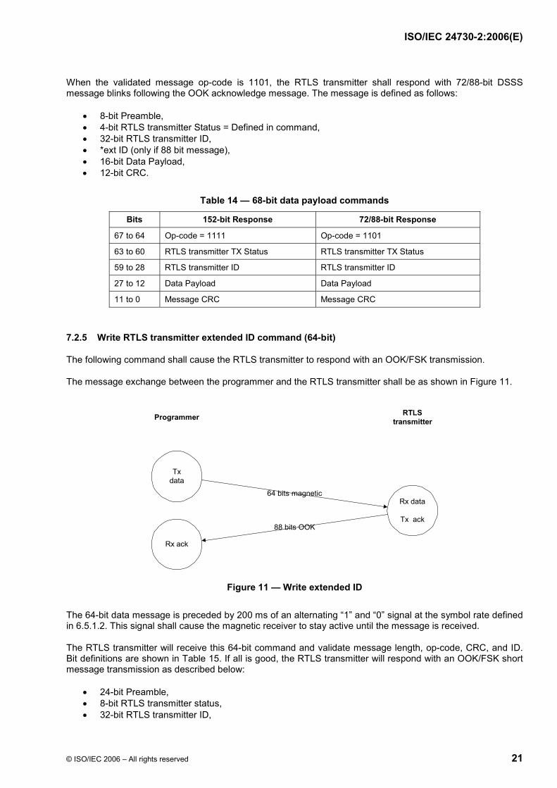
7.2.5 Write RTLS transmitter extended ID command (64-bit)
The following command shall cause the RTLS transmitter to respond with an OOK/FSK transmission.
The message exchange between the programmer and the RTLS transmitter shall be as shown in Figure 11.
Figure 11 — Write extended ID
The 64-bit data message is preceded by 200 ms of an alternating “1” and “0” signal at the symbol rate defined in 6.5.1.2. This signal shall cause the magnetic receiver to stay active until the message is received.
The RTLS transmitter will receive this 64-bit command and validate message length, op-code, CRC, and ID. Bit definitions are shown in Table 15. If all is good, the RTLS transmitter will respond with an OOK/FSK short message transmission as described below:
• 24-bit Preamble, • 8-bit RTLS transmitter status, • 32-bit RTLS transmitter ID,
Txdata
Rx data
Tx ack
Rx ack
88 bits OOK
64 bits magnetic
Programmer RTLStransmitter
BE49B7BBD066671DDBAE9F84BE28946CA9DF9DF2BA9E929378DC6DB9C7E5059464FF4B45A0F85E8B98E153907E03DE94EF30CDCC12FA6F50BA3323A074E163CA3931B7F7732B0AB51371595948E3757AA5E02727CEF3E6C8A365098C03D01663BB19E0DEEA9EB3D8C542CA64DEDFB03EB47A59A78D4BFB30E27F3AA4E3E48ABE0E29445BBE3A515170EEF94D8F0A266ABD3D64A8149D1D38892BBA9FB68D88E5E9ED33B5DB902E246D74B57FC88D2E035B
Ext
ern
e el
ektr
on
isch
e A
usl
eges
telle
-Beu
th-S
NV
sh
op
Sch
wei
zer.
No
rmen
-Ver
ein
igu
ng
ein
Jo
int
Ven
ture
mit
TF
V-K
dN
r.69
5027
8-ID
.22A
CD
6D3D
B9E
8827
C48
2982
DB
5940
737.
4-20
08-0
5-30
10:
35:4
8
ISO/IEC 24730-2:2006(E)
22 © ISO/IEC 2006 – All rights reserved
• 8-bit CRC ACK calculated on the magnetic message, • 16-bit CRC.
The RTLS transmitter DSSS message length shall be defined by the 16-bit extended ID value.
If the extended ID is set to 0x0000, the TIB/AEXB shall be 56 bits.
If the extended ID is non-zero, the TIB/AEXB shall be 72 bits.
Table 15 — 64-bit RTLS transmitter extended ID command
Bits Description
63 to 60 Op-code = "1000"
59 to 28 Message ID = RTLS transmitter ID (no wild card allowed)
27 to 12 RTLS transmitter Extended ID bits [47 to 32]
11 to 0 Message CRC
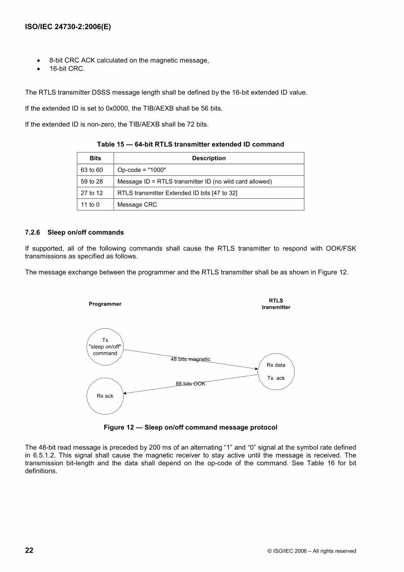
7.2.6 Sleep on/off commands
If supported, all of the following commands shall cause the RTLS transmitter to respond with OOK/FSK transmissions as specified as follows.
The message exchange between the programmer and the RTLS transmitter shall be as shown in Figure 12.
Figure 12 — Sleep on/off command message protocol
The 48-bit read message is preceded by 200 ms of an alternating “1” and “0” signal at the symbol rate defined in 6.5.1.2. This signal shall cause the magnetic receiver to stay active until the message is received. The transmission bit-length and the data shall depend on the op-code of the command. See Table 16 for bit definitions.
Tx"sleep on/off"
command
Rx data
Tx ack
Rx ack
88 bits OOK
48 bits magnetic
Programmer RTLStransmitter
BE49B7BBD066671DDBAE9F84BE28946CA9DF9DF2BA9E929378DC6DB9C7E5059464FF4B45A0F85E8B98E153907E03DE94EF30CDCC12FA6F50BA3323A074E163CA3931B7F7732B0AB51371595948E3757AA5E02727CEF3E6C8A365098C03D01663BB19E0DEEA9EB3D8C542CA64DEDFB03EB47A59A78D4BFB30E27F3AA4E3E48ABE0E29445BBE3A515170EEF94D8F0A266ABD3D64A8149D1D38892BBA9FB68D88E5E9ED33B5DB902E246D74B57FC88D2E035B
Ext
ern
e el
ektr
on
isch
e A
usl
eges
telle
-Beu
th-S
NV
sh
op
Sch
wei
zer.
No
rmen
-Ver
ein
igu
ng
ein
Jo
int
Ven
ture
mit
TF
V-K
dN
r.69
5027
8-ID
.22A
CD
6D3D
B9E
8827
C48
2982
DB
5940
737.
4-20
08-0
5-30
10:
35:4
8
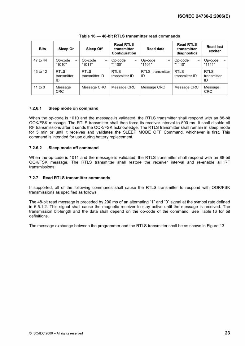
ISO/IEC 24730-2:2006(E)
© ISO/IEC 2006 – All rights reserved 23
Table 16 — 48-bit RTLS transmitter read commands
Bits Sleep On Sleep Off Read RTLS transmitter
Configuration Read data
Read RTLS transmitter diagnostics
Read last exciter
47 to 44 Op-code = "1010"
Op-code = "1011"
Op-code = "1100"
Op-code = "1101"
Op-code = "1110"
Op-code = "1111"
43 to 12 RTLS transmitter ID
RTLS transmitter ID
RTLS transmitter ID
RTLS transmitter ID
RTLS transmitter ID
RTLS transmitter ID
11 to 0 Message CRC
Message CRC Message CRC Message CRC Message CRC Message CRC
7.2.6.1 Sleep mode on command
When the op-code is 1010 and the message is validated, the RTLS transmitter shall respond with an 88-bit OOK/FSK message. The RTLS transmitter shall then force its receiver interval to 500 ms. It shall disable all RF transmissions after it sends the OOK/FSK acknowledge. The RTLS transmitter shall remain in sleep mode for 5 min or until it receives and validates the SLEEP MODE OFF Command, whichever is first. This command is intended for use during battery replacement.
7.2.6.2 Sleep mode off command
When the op-code is 1011 and the message is validated, the RTLS transmitter shall respond with an 88-bit OOK/FSK message. The RTLS transmitter shall restore the receiver interval and re-enable all RF transmissions.
7.2.7 Read RTLS transmitter commands
If supported, all of the following commands shall cause the RTLS transmitter to respond with OOK/FSK transmissions as specified as follows.
The 48-bit read message is preceded by 200 ms of an alternating “1” and “0” signal at the symbol rate defined in 6.5.1.2. This signal shall cause the magnetic receiver to stay active until the message is received. The transmission bit-length and the data shall depend on the op-code of the command. See Table 16 for bit definitions.
The message exchange between the programmer and the RTLS transmitter shall be as shown in Figure 13.
BE49B7BBD066671DDBAE9F84BE28946CA9DF9DF2BA9E929378DC6DB9C7E5059464FF4B45A0F85E8B98E153907E03DE94EF30CDCC12FA6F50BA3323A074E163CA3931B7F7732B0AB51371595948E3757AA5E02727CEF3E6C8A365098C03D01663BB19E0DEEA9EB3D8C542CA64DEDFB03EB47A59A78D4BFB30E27F3AA4E3E48ABE0E29445BBE3A515170EEF94D8F0A266ABD3D64A8149D1D38892BBA9FB68D88E5E9ED33B5DB902E246D74B57FC88D2E035B
Ext
ern
e el
ektr
on
isch
e A
usl
eges
telle
-Beu
th-S
NV
sh
op
Sch
wei
zer.
No
rmen
-Ver
ein
igu
ng
ein
Jo
int
Ven
ture
mit
TF
V-K
dN
r.69
5027
8-ID
.22A
CD
6D3D
B9E
8827
C48
2982
DB
5940
737.
4-20
08-0
5-30
10:
35:4
8
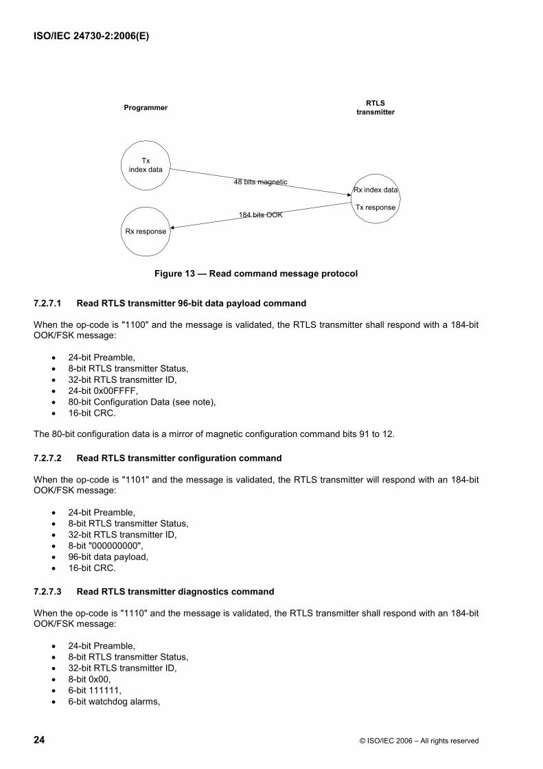
ISO/IEC 24730-2:2006(E)
24 © ISO/IEC 2006 – All rights reserved
Figure 13 — Read command message protocol
7.2.7.1 Read RTLS transmitter 96-bit data payload command
When the op-code is "1100" and the message is validated, the RTLS transmitter shall respond with a 184-bit OOK/FSK message:
• 24-bit Preamble, • 8-bit RTLS transmitter Status, • 32-bit RTLS transmitter ID, • 24-bit 0x00FFFF, • 80-bit Configuration Data (see note), • 16-bit CRC.
The 80-bit configuration data is a mirror of magnetic configuration command bits 91 to 12.
7.2.7.2 Read RTLS transmitter configuration command
When the op-code is "1101" and the message is validated, the RTLS transmitter will respond with an 184-bit OOK/FSK message:
• 24-bit Preamble, • 8-bit RTLS transmitter Status, • 32-bit RTLS transmitter ID, • 8-bit "000000000", • 96-bit data payload, • 16-bit CRC.
7.2.7.3 Read RTLS transmitter diagnostics command
When the op-code is "1110" and the message is validated, the RTLS transmitter shall respond with an 184-bit OOK/FSK message:
• 24-bit Preamble, • 8-bit RTLS transmitter Status, • 32-bit RTLS transmitter ID, • 8-bit 0x00, • 6-bit 111111, • 6-bit watchdog alarms,
Txindex data
Rx index data
Tx response
Rx response
184 bits OOK
48 bits magnetic
Programmer RTLStransmitter
BE49B7BBD066671DDBAE9F84BE28946CA9DF9DF2BA9E929378DC6DB9C7E5059464FF4B45A0F85E8B98E153907E03DE94EF30CDCC12FA6F50BA3323A074E163CA3931B7F7732B0AB51371595948E3757AA5E02727CEF3E6C8A365098C03D01663BB19E0DEEA9EB3D8C542CA64DEDFB03EB47A59A78D4BFB30E27F3AA4E3E48ABE0E29445BBE3A515170EEF94D8F0A266ABD3D64A8149D1D38892BBA9FB68D88E5E9ED33B5DB902E246D74B57FC88D2E035B
Ext
ern
e el
ektr
on
isch
e A
usl
eges
telle
-Beu
th-S
NV
sh
op
Sch
wei
zer.
No
rmen
-Ver
ein
igu
ng
ein
Jo
int
Ven
ture
mit
TF
V-K
dN
r.69
5027
8-ID
.22A
CD
6D3D
B9E
8827
C48
2982
DB
5940
737.
4-20
08-0
5-30
10:
35:4
8
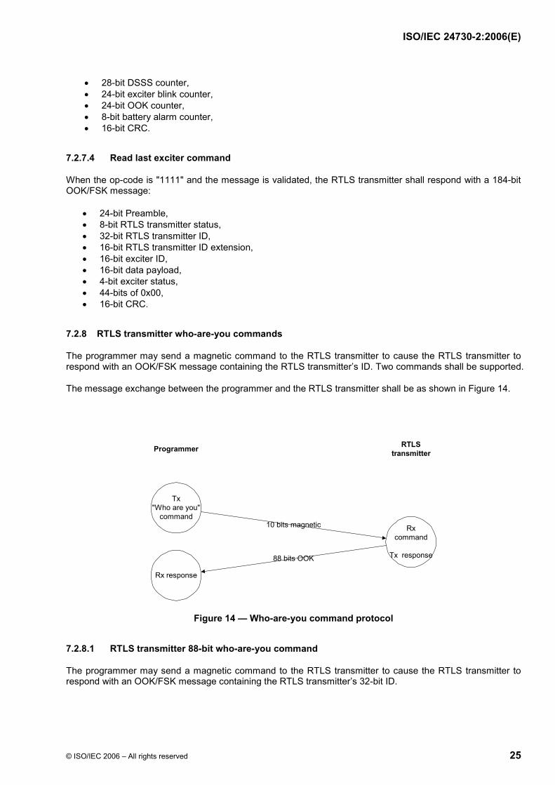
ISO/IEC 24730-2:2006(E)
© ISO/IEC 2006 – All rights reserved 25
• 28-bit DSSS counter, • 24-bit exciter blink counter, • 24-bit OOK counter, • 8-bit battery alarm counter, • 16-bit CRC.
7.2.7.4 Read last exciter command
When the op-code is "1111" and the message is validated, the RTLS transmitter shall respond with a 184-bit OOK/FSK message:
• 24-bit Preamble, • 8-bit RTLS transmitter status, • 32-bit RTLS transmitter ID, • 16-bit RTLS transmitter ID extension, • 16-bit exciter ID, • 16-bit data payload, • 4-bit exciter status, • 44-bits of 0x00, • 16-bit CRC.
7.2.8 RTLS transmitter who-are-you commands
The programmer may send a magnetic command to the RTLS transmitter to cause the RTLS transmitter to respond with an OOK/FSK message containing the RTLS transmitter’s ID. Two commands shall be supported.
The message exchange between the programmer and the RTLS transmitter shall be as shown in Figure 14.
Figure 14 — Who-are-you command protocol
7.2.8.1 RTLS transmitter 88-bit who-are-you command
The programmer may send a magnetic command to the RTLS transmitter to cause the RTLS transmitter to respond with an OOK/FSK message containing the RTLS transmitter’s 32-bit ID.
Tx"Who are you"
commandRx
command
Tx response
Rx response
88 bits OOK
10 bits magnetic
Programmer RTLStransmitter
BE49B7BBD066671DDBAE9F84BE28946CA9DF9DF2BA9E929378DC6DB9C7E5059464FF4B45A0F85E8B98E153907E03DE94EF30CDCC12FA6F50BA3323A074E163CA3931B7F7732B0AB51371595948E3757AA5E02727CEF3E6C8A365098C03D01663BB19E0DEEA9EB3D8C542CA64DEDFB03EB47A59A78D4BFB30E27F3AA4E3E48ABE0E29445BBE3A515170EEF94D8F0A266ABD3D64A8149D1D38892BBA9FB68D88E5E9ED33B5DB902E246D74B57FC88D2E035B
Ext
ern
e el
ektr
on
isch
e A
usl
eges
telle
-Beu
th-S
NV
sh
op
Sch
wei
zer.
No
rmen
-Ver
ein
igu
ng
ein
Jo
int
Ven
ture
mit
TF
V-K
dN
r.69
5027
8-ID
.22A
CD
6D3D
B9E
8827
C48
2982
DB
5940
737.
4-20
08-0
5-30
10:
35:4
8
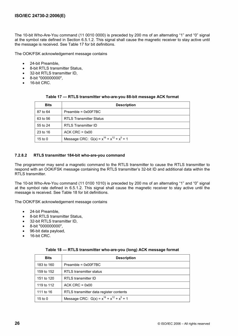
ISO/IEC 24730-2:2006(E)
26 © ISO/IEC 2006 – All rights reserved
The 10-bit Who-Are-You command (11 0010 0000) is preceded by 200 ms of an alternating “1” and “0” signal at the symbol rate defined in Section 6.5.1.2. This signal shall cause the magnetic receiver to stay active until the message is received. See Table 17 for bit definitions.
The OOK/FSK acknowledgement message contains
• 24-bit Preamble, • 8-bit RTLS transmitter Status, • 32-bit RTLS transmitter ID, • 8-bit "000000000", • 16-bit CRC.
Table 17 — RTLS transmitter who-are-you 88-bit message ACK format
Bits Description
87 to 64 Preamble = 0x00F7BC
63 to 56 RTLS Transmitter Status
55 to 24 RTLS Transmitter ID
23 to 16 ACK CRC = 0x00
15 to 0 Message CRC: G(x) = x16 + x12 + x5 + 1
7.2.8.2 RTLS transmitter 184-bit who-are-you command
The programmer may send a magnetic command to the RTLS transmitter to cause the RTLS transmitter to respond with an OOK/FSK message containing the RTLS transmitter’s 32-bit ID and additional data within the RTLS transmitter.
The 10-bit Who-Are-You command (11 0100 1010) is preceded by 200 ms of an alternating “1” and “0” signal at the symbol rate defined in 6.5.1.2. This signal shall cause the magnetic receiver to stay active until the message is received. See Table 18 for bit definitions.
The OOK/FSK acknowledgement message contains
• 24-bit Preamble, • 8-bit RTLS transmitter Status, • 32-bit RTLS transmitter ID, • 8-bit "000000000", • 96-bit data payload, • 16-bit CRC.
Table 18 — RTLS transmitter who-are-you (long) ACK message format
Bits Description
183 to 160 Preamble = 0x00F7BC
159 to 152 RTLS transmitter status
151 to 120 RTLS transmitter ID
119 to 112 ACK CRC = 0x00
111 to 16 RTLS transmitter data register contents
15 to 0 Message CRC: G(x) = x16 + x12 + x5 + 1
BE49B7BBD066671DDBAE9F84BE28946CA9DF9DF2BA9E929378DC6DB9C7E5059464FF4B45A0F85E8B98E153907E03DE94EF30CDCC12FA6F50BA3323A074E163CA3931B7F7732B0AB51371595948E3757AA5E02727CEF3E6C8A365098C03D01663BB19E0DEEA9EB3D8C542CA64DEDFB03EB47A59A78D4BFB30E27F3AA4E3E48ABE0E29445BBE3A515170EEF94D8F0A266ABD3D64A8149D1D38892BBA9FB68D88E5E9ED33B5DB902E246D74B57FC88D2E035B
Ext
ern
e el
ektr
on
isch
e A
usl
eges
telle
-Beu
th-S
NV
sh
op
Sch
wei
zer.
No
rmen
-Ver
ein
igu
ng
ein
Jo
int
Ven
ture
mit
TF
V-K
dN
r.69
5027
8-ID
.22A
CD
6D3D
B9E
8827
C48
2982
DB
5940
737.
4-20
08-0
5-30
10:
35:4
8
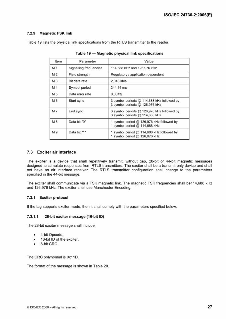
ISO/IEC 24730-2:2006(E)
© ISO/IEC 2006 – All rights reserved 27
7.2.9 Magnetic FSK link
Table 19 lists the physical link specifications from the RTLS transmitter to the reader.
Table 19 — Magnetic physical link specifications
Item Parameter Value
M 1 Signalling frequencies 114,688 kHz and 126,976 kHz
M 2 Field strength Regulatory / application dependent
M 3 Bit data rate 2,048 kb/s
M 4 Symbol period 244,14 ms
M 5 Data error rate 0,001%
M 6 Start sync 3 symbol periods @ 114,688 kHz followed by 3 symbol periods @ 126,976 kHz
M 7 End sync 3 symbol periods @ 126,976 kHz followed by 3 symbol periods @ 114,688 kHz
M 8 Data bit "0" 1 symbol period @ 126,976 kHz followed by 1 symbol period @ 114,688 kHz
M 9 Data bit "1" 1 symbol period @ 114,688 kHz followed by 1 symbol period @ 126,976 kHz
7.3 Exciter air interface
The exciter is a device that shall repetitively transmit, without gap, 28-bit or 44-bit magnetic messages designed to stimulate responses from RTLS transmitters. The exciter shall be a transmit-only device and shall not have an air interface receiver. The RTLS transmitter configuration shall change to the parameters specified in the 44-bit message.
The exciter shall communicate via a FSK magnetic link. The magnetic FSK frequencies shall be114,688 kHz and 126,976 kHz. The exciter shall use Manchester Encoding.
7.3.1 Exciter protocol
If the tag supports exciter mode, then it shall comply with the parameters specified below.
7.3.1.1 28-bit exciter message (16-bit ID)
The 28-bit exciter message shall include
• 4-bit Opcode, • 16-bit ID of the exciter, • 8-bit CRC.
The CRC polynomial is 0x11D.
The format of the message is shown in Table 20.
BE49B7BBD066671DDBAE9F84BE28946CA9DF9DF2BA9E929378DC6DB9C7E5059464FF4B45A0F85E8B98E153907E03DE94EF30CDCC12FA6F50BA3323A074E163CA3931B7F7732B0AB51371595948E3757AA5E02727CEF3E6C8A365098C03D01663BB19E0DEEA9EB3D8C542CA64DEDFB03EB47A59A78D4BFB30E27F3AA4E3E48ABE0E29445BBE3A515170EEF94D8F0A266ABD3D64A8149D1D38892BBA9FB68D88E5E9ED33B5DB902E246D74B57FC88D2E035B
Ext
ern
e el
ektr
on
isch
e A
usl
eges
telle
-Beu
th-S
NV
sh
op
Sch
wei
zer.
No
rmen
-Ver
ein
igu
ng
ein
Jo
int
Ven
ture
mit
TF
V-K
dN
r.69
5027
8-ID
.22A
CD
6D3D
B9E
8827
C48
2982
DB
5940
737.
4-20
08-0
5-30
10:
35:4
8
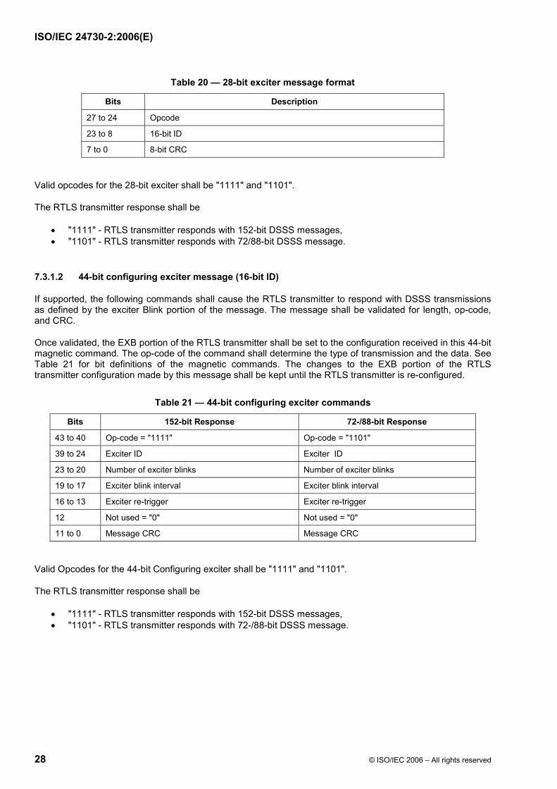
ISO/IEC 24730-2:2006(E)
28 © ISO/IEC 2006 – All rights reserved
Table 20 — 28-bit exciter message format
Bits Description
27 to 24 Opcode
23 to 8 16-bit ID
7 to 0 8-bit CRC
Valid opcodes for the 28-bit exciter shall be "1111" and "1101".
The RTLS transmitter response shall be
• "1111" - RTLS transmitter responds with 152-bit DSSS messages, • "1101" - RTLS transmitter responds with 72/88-bit DSSS message.
7.3.1.2 44-bit configuring exciter message (16-bit ID)
If supported, the following commands shall cause the RTLS transmitter to respond with DSSS transmissions as defined by the exciter Blink portion of the message. The message shall be validated for length, op-code, and CRC.
Once validated, the EXB portion of the RTLS transmitter shall be set to the configuration received in this 44-bit magnetic command. The op-code of the command shall determine the type of transmission and the data. See Table 21 for bit definitions of the magnetic commands. The changes to the EXB portion of the RTLS transmitter configuration made by this message shall be kept until the RTLS transmitter is re-configured.
Table 21 — 44-bit configuring exciter commands
Bits 152-bit Response 72-/88-bit Response
43 to 40 Op-code = "1111" Op-code = "1101"
39 to 24 Exciter ID Exciter ID
23 to 20 Number of exciter blinks Number of exciter blinks
19 to 17 Exciter blink interval Exciter blink interval
16 to 13 Exciter re-trigger Exciter re-trigger
12 Not used = "0" Not used = "0"
11 to 0 Message CRC Message CRC
Valid Opcodes for the 44-bit Configuring exciter shall be "1111" and "1101".
The RTLS transmitter response shall be
• "1111" - RTLS transmitter responds with 152-bit DSSS messages, • "1101" - RTLS transmitter responds with 72-/88-bit DSSS message.
BE49B7BBD066671DDBAE9F84BE28946CA9DF9DF2BA9E929378DC6DB9C7E5059464FF4B45A0F85E8B98E153907E03DE94EF30CDCC12FA6F50BA3323A074E163CA3931B7F7732B0AB51371595948E3757AA5E02727CEF3E6C8A365098C03D01663BB19E0DEEA9EB3D8C542CA64DEDFB03EB47A59A78D4BFB30E27F3AA4E3E48ABE0E29445BBE3A515170EEF94D8F0A266ABD3D64A8149D1D38892BBA9FB68D88E5E9ED33B5DB902E246D74B57FC88D2E035B
Ext
ern
e el
ektr
on
isch
e A
usl
eges
telle
-Beu
th-S
NV
sh
op
Sch
wei
zer.
No
rmen
-Ver
ein
igu
ng
ein
Jo
int
Ven
ture
mit
TF
V-K
dN
r.69
5027
8-ID
.22A
CD
6D3D
B9E
8827
C48
2982
DB
5940
737.
4-20
08-0
5-30
10:
35:4
8
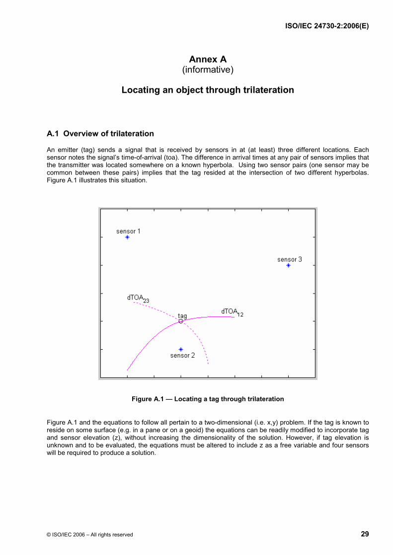
ISO/IEC 24730-2:2006(E)
© ISO/IEC 2006 – All rights reserved 29
Annex A (informative)
Locating an object through trilateration
A.1 Overview of trilateration
An emitter (tag) sends a signal that is received by sensors in at (at least) three different locations. Each sensor notes the signal’s time-of-arrival (toa). The difference in arrival times at any pair of sensors implies that the transmitter was located somewhere on a known hyperbola. Using two sensor pairs (one sensor may be common between these pairs) implies that the tag resided at the intersection of two different hyperbolas. Figure A.1 illustrates this situation.
Figure A.1 — Locating a tag through trilateration
Figure A.1 and the equations to follow all pertain to a two-dimensional (i.e. x,y) problem. If the tag is known to reside on some surface (e.g. in a pane or on a geoid) the equations can be readily modified to incorporate tag and sensor elevation (z), without increasing the dimensionality of the solution. However, if tag elevation is unknown and to be evaluated, the equations must be altered to include z as a free variable and four sensors will be required to produce a solution.
BE49B7BBD066671DDBAE9F84BE28946CA9DF9DF2BA9E929378DC6DB9C7E5059464FF4B45A0F85E8B98E153907E03DE94EF30CDCC12FA6F50BA3323A074E163CA3931B7F7732B0AB51371595948E3757AA5E02727CEF3E6C8A365098C03D01663BB19E0DEEA9EB3D8C542CA64DEDFB03EB47A59A78D4BFB30E27F3AA4E3E48ABE0E29445BBE3A515170EEF94D8F0A266ABD3D64A8149D1D38892BBA9FB68D88E5E9ED33B5DB902E246D74B57FC88D2E035B
Ext
ern
e el
ektr
on
isch
e A
usl
eges
telle
-Beu
th-S
NV
sh
op
Sch
wei
zer.
No
rmen
-Ver
ein
igu
ng
ein
Jo
int
Ven
ture
mit
TF
V-K
dN
r.69
5027
8-ID
.22A
CD
6D3D
B9E
8827
C48
2982
DB
5940
737.
4-20
08-0
5-30
10:
35:4
8

ISO/IEC 24730-2:2006(E)
30 © ISO/IEC 2006 – All rights reserved
A.2 Mathematical location solution
Let tx denote the time when the tag transmitted from location (x,y). The kth sensor, at location (xk, yk), will detect the signal at time toak = tx+ pk where pk denotes the time required for the signal to propagate from the tag to the sensor. This propagation time is equal to the tag-to-sensor separation divided by the speed of light (c) as indicated in the equation below
pk = sqrt( [x – xk]2 + [y – yk]
2) / c [1]
The unknown transmission time becomes unimportant when considering the difference in arrival times at two sensors (dTOAjk).
dTOAjk • toaj - toak = sqrt([x–xj]2+[y–yj]
2)/c - sqrt([x–xk]2+[y–yk]
2)/c [2]
Equation [2] was used to generate the hyperbolic segments shown in Figure 1 for both dTOA12 and dTOA23.
The following section details a method of solving for the intersection of these two hyperbolas. Equation pair [8] will produce two possible locations for this intersection, one real and the other (almost always) extraneous. An extraneous solution will not satisfy the original pair of dTOA equations and may be recognized by this failure.
A.3 Detailed equation derivation
For convenience, define δjk – c • dTOAjk. By squaring equation [2] above and collecting terms one obtains the relationship
½ { δjk
2 + [xj
2 - yj
2] - [xk
2 – yk
2] } + {xk - xj} • x + {yk - yj} • y = δjk • sqrt([x–xk]2+[y–yk]
2) [3]
Again, to simplify notation define λjk – ½ { δjk
2 + [xj
2 - yj
2] - [xk
2 – yk
2] }, then sensors 1,2 & 3 give the hyperbolic relationships
λ12 + {x2 – x1} • x + {y2 – y1} • y = δ12 • sqrt([x–x2]2+[y–y2]
2) [4a]
λ32 + {x2 – x3} • x + {y2 – y3} • y = δ32 • sqrt([x–x2]2+[y–y2]
2) [4b]
Subtracting these two shows that the location solution must lie on a line given by
(δ32• {x2 – x1} – δ12• {x2 – x3}) • x + (δ32• {y2 – y1} – δ12 • {y2 – y3}) • y + (δ32• λ12 – δ12• λ12) = 0 [5]
or equivalently y = m • x + b where
m = (δ32• {x2 – x1} – δ12• {x2 – x3}) / (δ32 • {y2 – y1} – δ12 • {y2 – y3}) [6a]
b = (δ32• λ12 – δ12 • δ12) / (δ32 • {y2 – y1} – δ12 • {y2 – y3}) [6b]
All that remains is to find the intersection of this line with either of the previously identified hyperbolas. Substituting y = m • x + b into hyperbolic relationship [4a], squaring and collecting terms gives the quadratic equation A • x2 + B • x + C = 0 where
A = [x2–x1]2 + 2m[x 2–x1][y2–y1] + m2[y2–y1]
2 - δ12
2 [1+ m2] [7a]
B = 2 {λ12[x2–x1] + λ12m[y2–y1] + b[x2–x1][y2–y1] + mb[y2–y1]
2 + δ12
2[x2 – mb + my2] } [7b]
C = λ12
2 + 2λ12b[y2–y1] + b2[y2–y1]2 - δ12
2[x2
2 + b2 - 2by2 + y2
2] [7c]
BE49B7BBD066671DDBAE9F84BE28946CA9DF9DF2BA9E929378DC6DB9C7E5059464FF4B45A0F85E8B98E153907E03DE94EF30CDCC12FA6F50BA3323A074E163CA3931B7F7732B0AB51371595948E3757AA5E02727CEF3E6C8A365098C03D01663BB19E0DEEA9EB3D8C542CA64DEDFB03EB47A59A78D4BFB30E27F3AA4E3E48ABE0E29445BBE3A515170EEF94D8F0A266ABD3D64A8149D1D38892BBA9FB68D88E5E9ED33B5DB902E246D74B57FC88D2E035B
Ext
ern
e el
ektr
on
isch
e A
usl
eges
telle
-Beu
th-S
NV
sh
op
Sch
wei
zer.
No
rmen
-Ver
ein
igu
ng
ein
Jo
int
Ven
ture
mit
TF
V-K
dN
r.69
5027
8-ID
.22A
CD
6D3D
B9E
8827
C48
2982
DB
5940
737.
4-20
08-0
5-30
10:
35:4
8
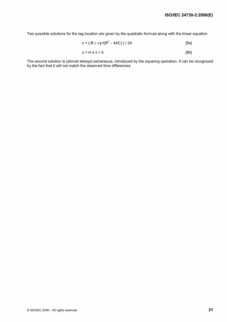
ISO/IEC 24730-2:2006(E)
© ISO/IEC 2006 – All rights reserved 31
Two possible solutions for the tag location are given by the quadratic formula along with the linear equation.
x = {-B ± sqrt(B2 – 4AC) } / 2A [8a]
y = m • x + b [8b]
The second solution is (almost always) extraneous, introduced by the squaring operation. It can be recognized by the fact that it will not match the observed time differences.
BE49B7BBD066671DDBAE9F84BE28946CA9DF9DF2BA9E929378DC6DB9C7E5059464FF4B45A0F85E8B98E153907E03DE94EF30CDCC12FA6F50BA3323A074E163CA3931B7F7732B0AB51371595948E3757AA5E02727CEF3E6C8A365098C03D01663BB19E0DEEA9EB3D8C542CA64DEDFB03EB47A59A78D4BFB30E27F3AA4E3E48ABE0E29445BBE3A515170EEF94D8F0A266ABD3D64A8149D1D38892BBA9FB68D88E5E9ED33B5DB902E246D74B57FC88D2E035B
Ext
ern
e el
ektr
on
isch
e A
usl
eges
telle
-Beu
th-S
NV
sh
op
Sch
wei
zer.
No
rmen
-Ver
ein
igu
ng
ein
Jo
int
Ven
ture
mit
TF
V-K
dN
r.69
5027
8-ID
.22A
CD
6D3D
B9E
8827
C48
2982
DB
5940
737.
4-20
08-0
5-30
10:
35:4
8

This page is intentionally blank.
BE49B7BBD066671DDBAE9F84BE28946CA9DF9DF2BA9E929378DC6DB9C7E5059464FF4B45A0F85E8B98E153907E03DE94EF30CDCC12FA6F50BA3323A074E163CA3931B7F7732B0AB51371595948E3757AA5E02727CEF3E6C8A365098C03D01663BB19E0DEEA9EB3D8C542CA64DEDFB03EB47A59A78D4BFB30E27F3AA4E3E48ABE0E29445BBE3A515170EEF94D8F0A266ABD3D64A8149D1D38892BBA9FB68D88E5E9ED33B5DB902E246D74B57FC88D2E035B
Ext
ern
e el
ektr
on
isch
e A
usl
eges
telle
-Beu
th-S
NV
sh
op
Sch
wei
zer.
No
rmen
-Ver
ein
igu
ng
ein
Jo
int
Ven
ture
mit
TF
V-K
dN
r.69
5027
8-ID
.22A
CD
6D3D
B9E
8827
C48
2982
DB
5940
737.
4-20
08-0
5-30
10:
35:4
8

ISO/IEC 24730-2:2006(E)
ICS 35.040 Price based on 31 pages
© ISO/IEC 2006 – All rights reserved
BE49B7BBD066671DDBAE9F84BE28946CA9DF9DF2BA9E929378DC6DB9C7E5059464FF4B45A0F85E8B98E153907E03DE94EF30CDCC12FA6F50BA3323A074E163CA3931B7F7732B0AB51371595948E3757AA5E02727CEF3E6C8A365098C03D01663BB19E0DEEA9EB3D8C542CA64DEDFB03EB47A59A78D4BFB30E27F3AA4E3E48ABE0E29445BBE3A515170EEF94D8F0A266ABD3D64A8149D1D38892BBA9FB68D88E5E9ED33B5DB902E246D74B57FC88D2E035B
Ext
ern
e el
ektr
on
isch
e A
usl
eges
telle
-Beu
th-S
NV
sh
op
Sch
wei
zer.
No
rmen
-Ver
ein
igu
ng
ein
Jo
int
Ven
ture
mit
TF
V-K
dN
r.69
5027
8-ID
.22A
CD
6D3D
B9E
8827
C48
2982
DB
5940
737.
4-20
08-0
5-30
10:
35:4
8