intrinsically safe solutions - notifier by honeywell | … safe solution system diagram..... 5...
TRANSCRIPT

Intrinsically Safe
Solutions
INSTALLATION MANUAL
DOC-01-029
04/12/14 Rev D
DOC-01-029
Documentation Feedback Your feedback helps us keep our documentation up to date and accurate. If you have any comments or suggestions
about our printed manuals you can email us.
Please include the following information:
Product name and version number (if applicable)
Manual part number and revision (found on the front cover)
Page number
Brief description of the content you think should be improved or corrected
Your suggestion for how to correct/improve documentation
Send email messages to:
Please note this email address is for documentation feedback only. If you have any technical issues, please contact you
nearest branch for technical support.
DOC-01-029
DOC-01-029 1
Table of Contents
Section 1 About this Manual ................................................................................................................... 2 1.1. Notes, Cautions and Warnings ....................................................................................................... 2 1.2. Related Documentation .................................................................................................................. 2
Section 2 Intrinsically Safe Solutions Overview ................................................................................... 3 2.1. Introduction .................................................................................................................................... 3 2.2. Intrinsically Safe Area Classification ............................................................................................. 3 2.3. Intrinsically Safe Solution System Diagram ................................................................................... 5
Section 3 List of Recommended Devices ............................................................................................. 6 3.1. Intrinsic Safety Barrier ................................................................................................................... 6 3.2. Intrinsic Safety Barrier Enclosure................................................................................................... 6 3.3. Intrinsically Safe Devices ............................................................................................................... 6
Section 4 Installation Information .......................................................................................................... 7 4.1. Intrinsically Safe Solution for IS conventional devices .................................................................. 7 4.1.1 Wiring schematic for IS conventional devices .......................................................................8 4.2. Intrinsically Safe Solution for IS addressable devices .................................................................... 9 4.3. Intrinsically Safe Solution for IS sounders and beacons............................................................... 10
DOC-01-029 Section 1 About this Manual
DOC-01-029 2
Section 1 About this Manual
1.1. Notes, Cautions and Warnings
This manual contains notes, cautions and warnings to alert the reader as follows:
NOTE: Supplement information for a topic such as tips and references.
CAUTION: Information about procedures that could cause programming errors, runtime errors, or equipment damage.
WARNING: Indicates information about procedures that could cause irreversible equipment damage, irreversible loss of programming data or personal injury.
1.2. Related Documentation
Related documentation:
Title Document
Number
CFP-16 Operation, Installation & Programming manual DOC-01-022
AFP-2800-2802 Operation, Installation & Programming manual DOC-01-010
MTL 5500 Series Instruction manual INM5500
MTL 7700 Series Instruction manual INM7700
Y72221 Intrinsically Safety Barrier for Addressable Detection
technical datasheet
IDX-751-IMX-1-
y72221-768-415
DX Enclosures for MTL5000/7000 Series INM57ENC
System Sensor 1151EIS Installation and Maintenance Instructions D100-59-00
System Sensor 5451EIS Product Specification D400-50-00
IS-A105N Instruction manual IS 4501
IS-L101L Instruction manual IS 4601
IS-mA1 Instruction manual IS 5001
IS-mB1 Instruction manual IS 5002
IS-mC1 Instruction manual IS 5003
WCP3-1 Technical datasheet KAC_IS-WCP3-1
DOC-01-029 Section 2 Intrinsically Safe Solutions Overview
DOC-01-029 3
Section 2 Intrinsically Safe Solutions Overview
2.1. Introduction
This document outlines the intrinsically safe solutions which include a list of recommended intrinsic
safety barriers and intrinsically safe devices that are compatible with the range of Notifier products
with the installation information.
Intrinsically safety (IS) is a low-energy signalling technique applied to electrical equipment and
wiring in hazardous areas for safe operation by limiting the energy available for ignition. A hazardous
area may contain flammable gasses, vapours or combustible dusts which can cause a fire or explosion
when a source of ignition is present.
The intrinsically safe solutions require the installation of an intrinsic safety barrier with compatible
intrinsically safe devices and in accordance with the manufacturer’s installation requirements.
NOTE: The intrinsically safe solution must be installed and tested by a qualified technical person in accordance with all appropriate standards which may include reference to AS60079.17 and in accordance with the instructions contained here.
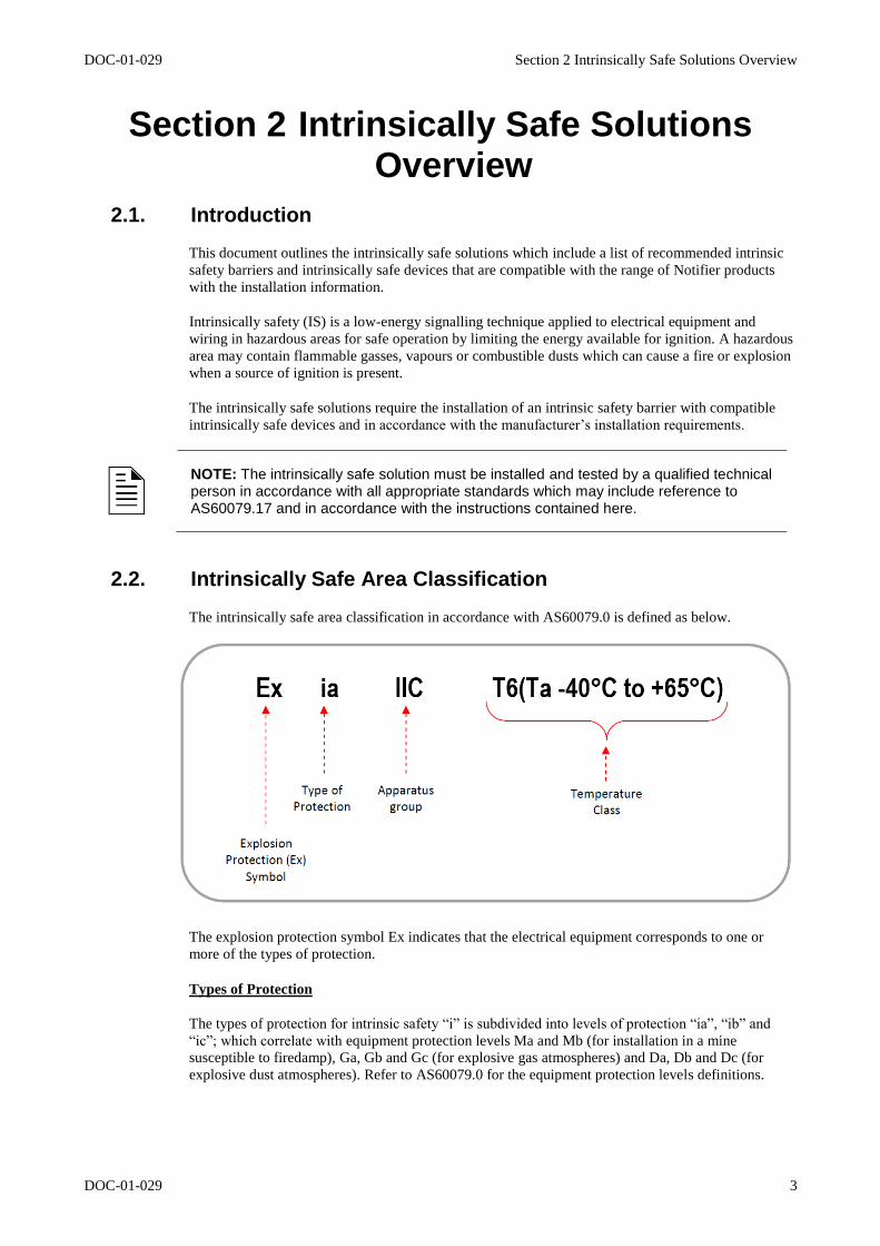
2.2. Intrinsically Safe Area Classification
The intrinsically safe area classification in accordance with AS60079.0 is defined as below.
The explosion protection symbol Ex indicates that the electrical equipment corresponds to one or
more of the types of protection.
Types of Protection
The types of protection for intrinsic safety “i” is subdivided into levels of protection “ia”, “ib” and
“ic”; which correlate with equipment protection levels Ma and Mb (for installation in a mine
susceptible to firedamp), Ga, Gb and Gc (for explosive gas atmospheres) and Da, Db and Dc (for
explosive dust atmospheres). Refer to AS60079.0 for the equipment protection levels definitions.
DOC-01-029 Section 2 Intrinsically Safe Solutions Overview
DOC-01-029 4
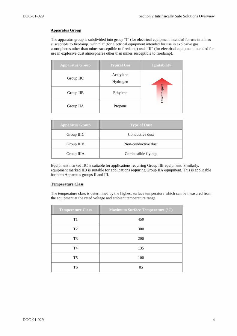
Apparatus Group
The apparatus group is subdivided into group “I” (for electrical equipment intended for use in mines
susceptible to firedamp) with “II” (for electrical equipment intended for use in explosive gas
atmospheres other than mines susceptible to firedamp) and “III” (for electrical equipment intended for
use in explosive dust atmospheres other than mines susceptible to firedamp).
Apparatus Group Typical Gas Ignitability
Group IIC Acetylene
Hydrogen
Group IIB Ethylene
Group IIA Propane
Apparatus Group Type of Dust
Group IIIC Conductive dust
Group IIIB Non-conductive dust
Group IIIA Combustible flyings
Equipment marked IIC is suitable for applications requiring Group IIB equipment. Similarly,
equipment marked IIB is suitable for applications requiring Group IIA equipment. This is applicable
for both Apparatus groups II and III.
Temperature Class
The temperature class is determined by the highest surface temperature which can be measured from
the equipment at the rated voltage and ambient temperature range.
Temperature Class Maximum Surface Temperature (°C)
T1 450
T2 300
T3 200
T4 135
T5 100
T6 85
DOC-01-029 Section 2 Intrinsically Safe Solutions Overview
DOC-01-029 5
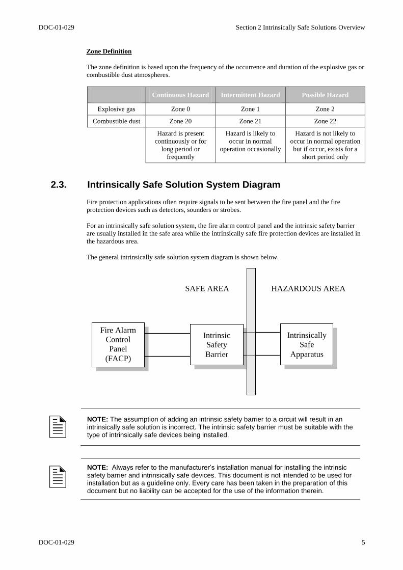
Zone Definition
The zone definition is based upon the frequency of the occurrence and duration of the explosive gas or
combustible dust atmospheres.
Continuous Hazard Intermittent Hazard Possible Hazard
Explosive gas Zone 0 Zone 1 Zone 2
Combustible dust Zone 20 Zone 21 Zone 22
Hazard is present
continuously or for
long period or
frequently
Hazard is likely to
occur in normal
operation occasionally
Hazard is not likely to
occur in normal operation
but if occur, exists for a
short period only
2.3. Intrinsically Safe Solution System Diagram
Fire protection applications often require signals to be sent between the fire panel and the fire
protection devices such as detectors, sounders or strobes.
For an intrinsically safe solution system, the fire alarm control panel and the intrinsic safety barrier
are usually installed in the safe area while the intrinsically safe fire protection devices are installed in
the hazardous area.
The general intrinsically safe solution system diagram is shown below.
NOTE: The assumption of adding an intrinsic safety barrier to a circuit will result in an intrinsically safe solution is incorrect. The intrinsic safety barrier must be suitable with the type of intrinsically safe devices being installed.
NOTE: Always refer to the manufacturer’s installation manual for installing the intrinsic safety barrier and intrinsically safe devices. This document is not intended to be used for installation but as a guideline only. Every care has been taken in the preparation of this document but no liability can be accepted for the use of the information therein.
Fire Alarm
Control
Panel
(FACP)
Intrinsically
Safe
Apparatus
HAZARDOUS AREA SAFE AREA
Intrinsic
Safety
Barrier
DOC-01-029 Section 3 List of Recommended Devices
DOC-01-029 6
Section 3 List of Recommended Devices
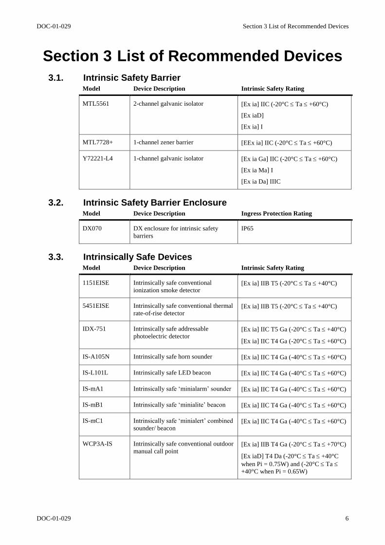
3.1. Intrinsic Safety Barrier Model Device Description Intrinsic Safety Rating
MTL5561
2-channel galvanic isolator [Ex ia] IIC (-20°C Ta +60°C)
[Ex iaD]
[Ex ia] I
MTL7728+ 1-channel zener barrier [EEx ia] IIC (-20°C Ta +60°C)
Y72221-L4 1-channel galvanic isolator [Ex ia Ga] IIC (-20°C Ta +60°C)
[Ex ia Ma] I
[Ex ia Da] IIIC
3.2. Intrinsic Safety Barrier Enclosure Model Device Description Ingress Protection Rating
DX070 DX enclosure for intrinsic safety
barriers
IP65
3.3. Intrinsically Safe Devices Model Device Description Intrinsic Safety Rating
1151EISE Intrinsically safe conventional
ionization smoke detector [Ex ia] IIB T5 (-20°C Ta +40°C)
5451EISE Intrinsically safe conventional thermal
rate-of-rise detector [Ex ia] IIB T5 (-20°C Ta +40°C)
IDX-751 Intrinsically safe addressable
photoelectric detector [Ex ia] IIC T5 Ga (-20°C Ta +40°C)
[Ex ia] IIC T4 Ga (-20°C Ta +60°C)
IS-A105N Intrinsically safe horn sounder [Ex ia] IIC T4 Ga (-40°C Ta +60°C)
IS-L101L Intrinsically safe LED beacon [Ex ia] IIC T4 Ga (-40°C Ta +60°C)
IS-mA1 Intrinsically safe ‘minialarm’ sounder [Ex ia] IIC T4 Ga (-40°C Ta +60°C)
IS-mB1 Intrinsically safe ‘minialite’ beacon [Ex ia] IIC T4 Ga (-40°C Ta +60°C)
IS-mC1 Intrinsically safe ‘minialert’ combined
sounder/ beacon [Ex ia] IIC T4 Ga (-40°C Ta +60°C)
WCP3A-IS Intrinsically safe conventional outdoor
manual call point [Ex ia] IIB T4 Ga (-20°C Ta +70°C)
[Ex iaD] T4 Da (-20°C Ta +40°C
when Pi = 0.75W) and (-20°C Ta
+40°C when Pi = 0.65W)
DOC-01-029 Section 4 Installation Information
DOC-01-029 7
Section 4 Installation Information
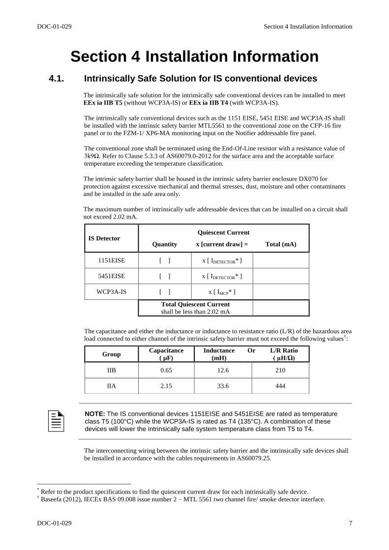
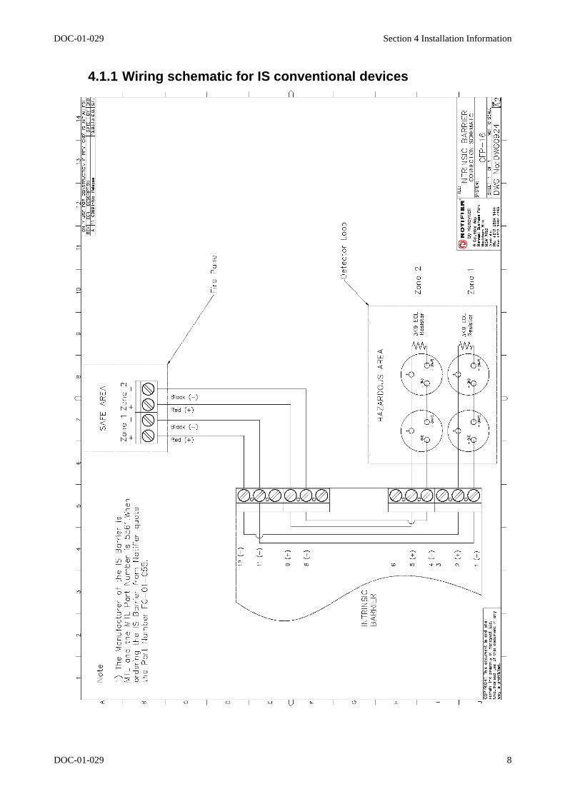
4.1. Intrinsically Safe Solution for IS conventional devices
The intrinsically safe solution for the intrinsically safe conventional devices can be installed to meet
EEx ia IIB T5 (without WCP3A-IS) or EEx ia IIB T4 (with WCP3A-IS).
The intrinsically safe conventional devices such as the 1151 EISE, 5451 EISE and WCP3A-IS shall
be installed with the intrinsic safety barrier MTL5561 to the conventional zone on the CFP-16 fire
panel or to the FZM-1/ XP6-MA monitoring input on the Notifier addressable fire panel.
The conventional zone shall be terminated using the End-Of-Line resistor with a resistance value of
3k9Ω. Refer to Clause 5.3.3 of AS60079.0-2012 for the surface area and the acceptable surface
temperature exceeding the temperature classification.
The intrinsic safety barrier shall be housed in the intrinsic safety barrier enclosure DX070 for
protection against excessive mechanical and thermal stresses, dust, moisture and other contaminants
and be installed in the safe area only.
The maximum number of intrinsically safe addressable devices that can be installed on a circuit shall
not exceed 2.02 mA.
The capacitance and either the inductance or inductance to resistance ratio (L/R) of the hazardous area
load connected to either channel of the intrinsic safety barrier must not exceed the following values†:
NOTE: The IS conventional devices 1151EISE and 5451EISE are rated as temperature class T5 (100°C) while the WCP3A-IS is rated as T4 (135°C). A combination of these devices will lower the intrinsically safe system temperature class from T5 to T4.
The interconnecting wiring between the intrinsic safety barrier and the intrinsically safe devices shall
be installed in accordance with the cables requirements in AS60079.25.
* Refer to the product specifications to find the quiescent current draw for each intrinsically safe device.
† Baseefa (2012), IECEx BAS 09.008 issue number 2 – MTL 5561 two channel fire/ smoke detector interface.
IS Detector Quiescent Current
Quantity x [current draw] = Total (mA)
1151EISE [ ] x [ IDETECTOR* ]
5451EISE [ ] x [ IDETECTOR* ]
WCP3A-IS [ ] x [ IMCP* ]
Total Quiescent Current
shall be less than 2.02 mA
Group Capacitance
( µF)
Inductance
(mH)
Or L/R Ratio
( µH/Ω)
IIB 0.65 12.6 210
IIA 2.15 33.6 444
DOC-01-029 Section 4 Installation Information
DOC-01-029 8
4.1.1 Wiring schematic for IS conventional devices
DOC-01-029 Section 4 Installation Information
DOC-01-029 9
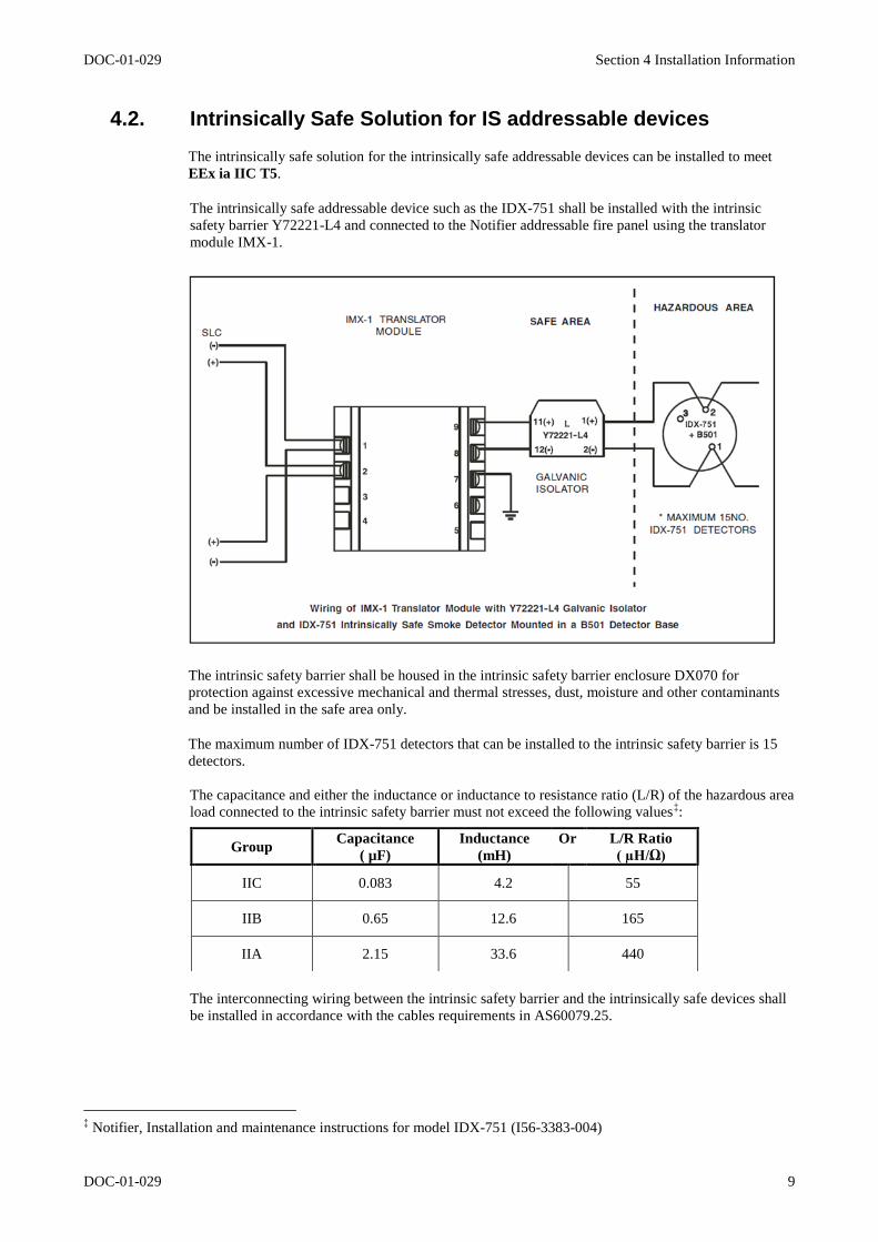
4.2. Intrinsically Safe Solution for IS addressable devices
The intrinsically safe solution for the intrinsically safe addressable devices can be installed to meet
EEx ia IIC T5.
The intrinsically safe addressable device such as the IDX-751 shall be installed with the intrinsic
safety barrier Y72221-L4 and connected to the Notifier addressable fire panel using the translator
module IMX-1.
The intrinsic safety barrier shall be housed in the intrinsic safety barrier enclosure DX070 for
protection against excessive mechanical and thermal stresses, dust, moisture and other contaminants
and be installed in the safe area only.
The maximum number of IDX-751 detectors that can be installed to the intrinsic safety barrier is 15
detectors.
The capacitance and either the inductance or inductance to resistance ratio (L/R) of the hazardous area
load connected to the intrinsic safety barrier must not exceed the following values‡:
The interconnecting wiring between the intrinsic safety barrier and the intrinsically safe devices shall
be installed in accordance with the cables requirements in AS60079.25.
‡ Notifier, Installation and maintenance instructions for model IDX-751 (I56-3383-004)
Group Capacitance
( µF)
Inductance
(mH)
Or L/R Ratio
( µH/Ω)
IIC 0.083 4.2 55
IIB 0.65 12.6 165
IIA 2.15 33.6 440
DOC-01-029 Section 4 Installation Information
DOC-01-029 10
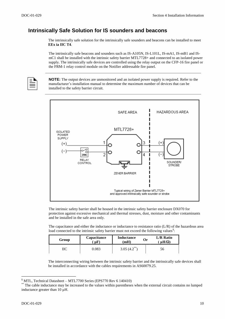
Intrinsically Safe Solution for IS sounders and beacons
The intrinsically safe solution for the intrinsically safe sounders and beacons can be installed to meet
EEx ia IIC T4.
The intrinsically safe beacons and sounders such as IS-A105N, IS-L101L, IS-mA1, IS-mB1 and IS-
mC1 shall be installed with the intrinsic safety barrier MTL7728+ and connected to an isolated power
supply. The intrinsically safe devices are controlled using the relay output on the CFP-16 fire panel or
the FRM-1 relay control module on the Notifier addressable fire panel.
NOTE: The output devices are unmonitored and an isolated power supply is required. Refer to the
manufacturer’s installation manual to determine the maximum number of devices that can be
installed to the safety barrier circuit.
The intrinsic safety barrier shall be housed in the intrinsic safety barrier enclosure DX070 for
protection against excessive mechanical and thermal stresses, dust, moisture and other contaminants
and be installed in the safe area only.
The capacitance and either the inductance or inductance to resistance ratio (L/R) of the hazardous area
load connected to the intrinsic safety barrier must not exceed the following values§:
The interconnecting wiring between the intrinsic safety barrier and the intrinsically safe devices shall
be installed in accordance with the cables requirements in AS60079.25.
§ MTL, Technical Datasheet – MTL7700 Series (EPS770 Rev 6 140410)
** The cable inductance may be increased to the values within parentheses when the external circuit contains no lumped
inductance greater than 10 µH.
Group Capacitance
( µF)
Inductance
(mH) Or
L/R Ratio
( µH/Ω)
IIC 0.083 3.05 (4.2**
) 56

DOC-01-029 11

DOC-01-029 12

DOC-01-029 13

New South Wales (Head Office) 9 Columbia Way Baulkham Hills NSW 2153 ph +61 (0)2 9899-4155 fax +61 (0)2 9899-4156
New Zealand 264 Mt Eden Road Mt Eden 1024 ph +64 (0)9 623 5050 fax +64 (0)9 623 5060