introduction to kg-tower tray & packed tower sizing...
TRANSCRIPT
Rev 54/2006
INTRODUCTION TO KG-TOWER®
Tray & Packed Tower Sizing Software Program
Version 2.0
Visit our website at www.koch-glitsch.com
KG-TOWER® Software
---- CONFIDENTIAL ----The information contained herein is the confidential and proprietary property of Koch-Glitsch and is not to be copied,reproduced or disclosed to others in whole or in part without prior written consent of Koch-Glitsch. THERE ARE NOWARRANTIES, EXPRESSED OR IMPLIED, INCLUDING BUT NOT LIMITED TO, WARRANTIES OF MERCHANTABILITY ORFITNESS FOR A PARTICULAR PURPOSE ASSOCIATED WITH THE INSTALLATION, OPERATION OR OTHER USE OF THESOFTWARE.
© 2004-2006 Koch-Glitsch, LP. All rights reserved. 2
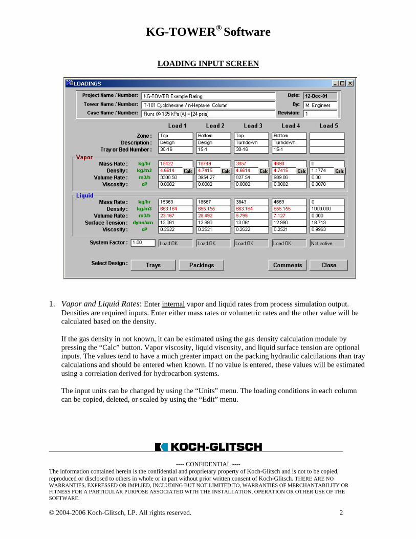
LOADING INPUT SCREEN
1. Vapor and Liquid Rates: Enter internal vapor and liquid rates from process simulation output.
Densities are required inputs. Enter either mass rates or volumetric rates and the other value will becalculated based on the density.
If the gas density in not known, it can be estimated using the gas density calculation module bypressing the “Calc” button. Vapor viscosity, liquid viscosity, and liquid surface tension are optionalinputs. The values tend to have a much greater impact on the packing hydraulic calculations than traycalculations and should be entered when known. If no value is entered, these values will be estimatedusing a correlation derived for hydrocarbon systems.
The input units can be changed by using the “Units” menu. The loading conditions in each columncan be copied, deleted, or scaled by using the “Edit” menu.
KG-TOWER® Software
---- CONFIDENTIAL ----The information contained herein is the confidential and proprietary property of Koch-Glitsch and is not to be copied,reproduced or disclosed to others in whole or in part without prior written consent of Koch-Glitsch. THERE ARE NOWARRANTIES, EXPRESSED OR IMPLIED, INCLUDING BUT NOT LIMITED TO, WARRANTIES OF MERCHANTABILITY ORFITNESS FOR A PARTICULAR PURPOSE ASSOCIATED WITH THE INSTALLATION, OPERATION OR OTHER USE OF THESOFTWARE.
© 2004-2006 Koch-Glitsch, LP. All rights reserved. 3
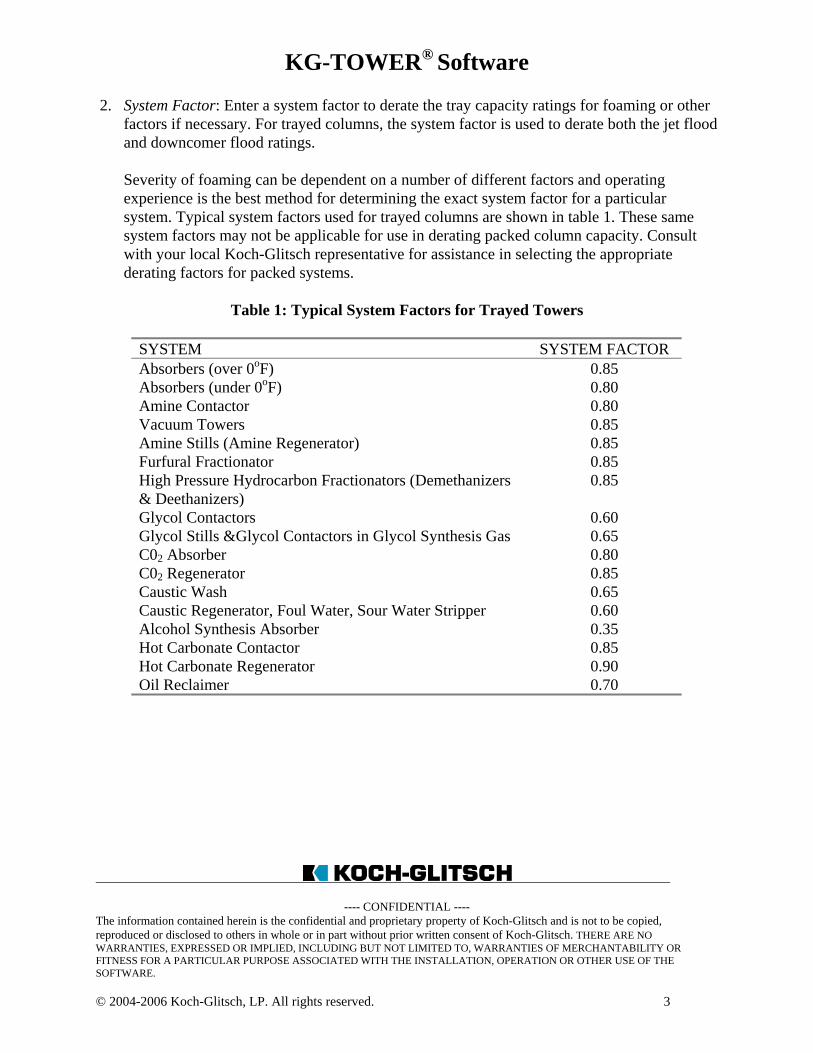
2. System Factor: Enter a system factor to derate the tray capacity ratings for foaming or otherfactors if necessary. For trayed columns, the system factor is used to derate both the jet floodand downcomer flood ratings.
Severity of foaming can be dependent on a number of different factors and operatingexperience is the best method for determining the exact system factor for a particularsystem. Typical system factors used for trayed columns are shown in table 1. These samesystem factors may not be applicable for use in derating packed column capacity. Consultwith your local Koch-Glitsch representative for assistance in selecting the appropriatederating factors for packed systems.
Table 1: Typical System Factors for Trayed Towers
SYSTEM SYSTEM FACTORAbsorbers (over 0oF) 0.85Absorbers (under 0oF) 0.80Amine Contactor 0.80Vacuum Towers 0.85Amine Stills (Amine Regenerator) 0.85Furfural Fractionator 0.85High Pressure Hydrocarbon Fractionators (Demethanizers& Deethanizers)
0.85
Glycol Contactors 0.60Glycol Stills &Glycol Contactors in Glycol Synthesis Gas 0.65C02 Absorber 0.80C02 Regenerator 0.85Caustic Wash 0.65Caustic Regenerator, Foul Water, Sour Water Stripper 0.60Alcohol Synthesis Absorber 0.35Hot Carbonate Contactor 0.85Hot Carbonate Regenerator 0.90Oil Reclaimer 0.70
KG-TOWER® Software
---- CONFIDENTIAL ----The information contained herein is the confidential and proprietary property of Koch-Glitsch and is not to be copied,reproduced or disclosed to others in whole or in part without prior written consent of Koch-Glitsch. THERE ARE NOWARRANTIES, EXPRESSED OR IMPLIED, INCLUDING BUT NOT LIMITED TO, WARRANTIES OF MERCHANTABILITY ORFITNESS FOR A PARTICULAR PURPOSE ASSOCIATED WITH THE INSTALLATION, OPERATION OR OTHER USE OF THESOFTWARE.
© 2004-2006 Koch-Glitsch, LP. All rights reserved. 4
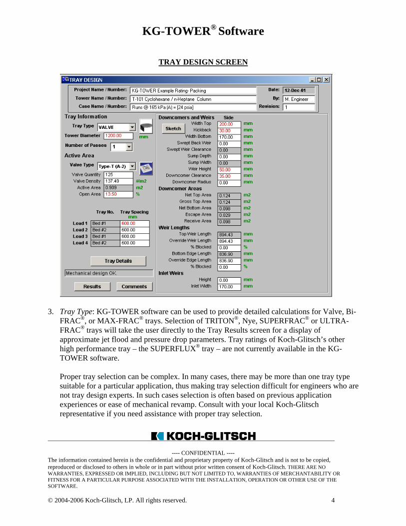
TRAY DESIGN SCREEN
3. Tray Type: KG-TOWER software can be used to provide detailed calculations for Valve, Bi-FRAC®, or MAX-FRAC® trays. Selection of TRITON®, Nye, SUPERFRAC® or ULTRA-FRAC® trays will take the user directly to the Tray Results screen for a display ofapproximate jet flood and pressure drop parameters. Tray ratings of Koch-Glitsch’s otherhigh performance tray – the SUPERFLUX® tray – are not currently available in the KG-TOWER software.
Proper tray selection can be complex. In many cases, there may be more than one tray typesuitable for a particular application, thus making tray selection difficult for engineers who arenot tray design experts. In such cases selection is often based on previous applicationexperiences or ease of mechanical revamp. Consult with your local Koch-Glitschrepresentative if you need assistance with proper tray selection.
KG-TOWER® Software
---- CONFIDENTIAL ----The information contained herein is the confidential and proprietary property of Koch-Glitsch and is not to be copied,reproduced or disclosed to others in whole or in part without prior written consent of Koch-Glitsch. THERE ARE NOWARRANTIES, EXPRESSED OR IMPLIED, INCLUDING BUT NOT LIMITED TO, WARRANTIES OF MERCHANTABILITY ORFITNESS FOR A PARTICULAR PURPOSE ASSOCIATED WITH THE INSTALLATION, OPERATION OR OTHER USE OF THESOFTWARE.
© 2004-2006 Koch-Glitsch, LP. All rights reserved. 5
4. Tower Diameter: The column diameter input units can be set for feet, inches, millimeters ormeters by selection of “Custom” under the “Units” pull-down menu.
When sizing new columns, the tower diameter may be estimated using the tools menu. Thiswill require some specification of the number of passes, tray spacing, and design floodingvalues.
Caution should be used when rating tray columns with column diameters less than2.5 ft [762 mm] as these trays may require special mechanical tray construction (cartridge /post supported trays with envelope downcomers) that may not be accurately accounted forusing KG-TOWER software.
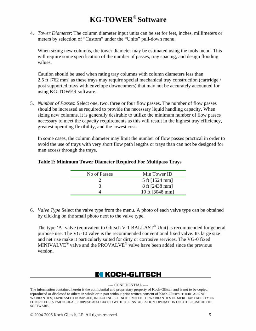
5. Number of Passes: Select one, two, three or four flow passes. The number of flow passesshould be increased as required to provide the necessary liquid handling capacity. Whensizing new columns, it is generally desirable to utilize the minimum number of flow passesnecessary to meet the capacity requirements as this will result in the highest tray efficiency,greatest operating flexibility, and the lowest cost.
In some cases, the column diameter may limit the number of flow passes practical in order toavoid the use of trays with very short flow path lengths or trays than can not be designed forman access through the trays.
Table 2: Minimum Tower Diameter Required For Multipass Trays
No of Passes Min Tower ID2 5 ft [1524 mm]3 8 ft [2438 mm]4 10 ft [3048 mm]
6. Valve Type Select the valve type from the menu. A photo of each valve type can be obtainedby clicking on the small photo next to the valve type.
The type ‘A’ valve (equivalent to Glitsch V-1 BALLAST® Unit) is recommended for generalpurpose use. The VG-10 valve is the recommended conventional fixed valve. Its large sizeand net rise make it particularly suited for dirty or corrosive services. The VG-0 fixedMINIVALVE® valve and the PROVALVE® valve have been added since the previousversion.
KG-TOWER® Software
---- CONFIDENTIAL ----The information contained herein is the confidential and proprietary property of Koch-Glitsch and is not to be copied,reproduced or disclosed to others in whole or in part without prior written consent of Koch-Glitsch. THERE ARE NOWARRANTIES, EXPRESSED OR IMPLIED, INCLUDING BUT NOT LIMITED TO, WARRANTIES OF MERCHANTABILITY ORFITNESS FOR A PARTICULAR PURPOSE ASSOCIATED WITH THE INSTALLATION, OPERATION OR OTHER USE OF THESOFTWARE.
© 2004-2006 Koch-Glitsch, LP. All rights reserved. 6
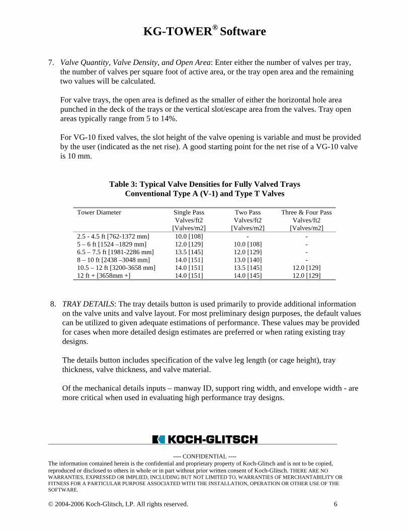
7. Valve Quantity, Valve Density, and Open Area: Enter either the number of valves per tray,the number of valves per square foot of active area, or the tray open area and the remainingtwo values will be calculated.
For valve trays, the open area is defined as the smaller of either the horizontal hole areapunched in the deck of the trays or the vertical slot/escape area from the valves. Tray openareas typically range from 5 to 14%.
For VG-10 fixed valves, the slot height of the valve opening is variable and must be providedby the user (indicated as the net rise). A good starting point for the net rise of a VG-10 valveis 10 mm.
Table 3: Typical Valve Densities for Fully Valved TraysConventional Type A (V-1) and Type T Valves
Tower Diameter Single PassValves/ft2
[Valves/m2]
Two PassValves/ft2
[Valves/m2]
Three & Four PassValves/ft2
[Valves/m2]2.5 - 4.5 ft [762-1372 mm] 10.0 [108] - -5 – 6 ft [1524 –1829 mm] 12.0 [129] 10.0 [108] -6.5 – 7.5 ft [1981-2286 mm] 13.5 [145] 12.0 [129] -8 – 10 ft [2438 –3048 mm] 14.0 [151] 13.0 [140] -10.5 – 12 ft [3200-3658 mm] 14.0 [151] 13.5 [145] 12.0 [129]12 ft + [3658mm +] 14.0 [151] 14.0 [145] 12.0 [129]
8. TRAY DETAILS: The tray details button is used primarily to provide additional informationon the valve units and valve layout. For most preliminary design purposes, the default valuescan be utilized to given adequate estimations of performance. These values may be providedfor cases when more detailed design estimates are preferred or when rating existing traydesigns.
The details button includes specification of the valve leg length (or cage height), traythickness, valve thickness, and valve material.
Of the mechanical details inputs – manway ID, support ring width, and envelope width - aremore critical when used in evaluating high performance tray designs.
KG-TOWER® Software
---- CONFIDENTIAL ----The information contained herein is the confidential and proprietary property of Koch-Glitsch and is not to be copied,reproduced or disclosed to others in whole or in part without prior written consent of Koch-Glitsch. THERE ARE NOWARRANTIES, EXPRESSED OR IMPLIED, INCLUDING BUT NOT LIMITED TO, WARRANTIES OF MERCHANTABILITY ORFITNESS FOR A PARTICULAR PURPOSE ASSOCIATED WITH THE INSTALLATION, OPERATION OR OTHER USE OF THESOFTWARE.
© 2004-2006 Koch-Glitsch, LP. All rights reserved. 7
9. TRAY GEOMETRY: Downcomer widths (top and bottom), weir heights, downcomerclearances, and tray spacings must be provided or estimated to complete the traycalculations. Additional tray features such as weir blocks (or picket fence weirs), swept backweirs, radius-tip downcomers, recessed inlet sumps, and inlet weirs are also supported withKG-TOWER software and may be input when applicable. For clarification on the meaningof these provided variables, select the ‘sketch’ button to see a pictorial view of theseparameters.
When sizing new columns, preliminary downcomer sizes can be estimated using the toolsmenu.
Proper definition of tray geometry requires some experience to ensure that the design is notonly optimized from the process standpoint, but also to ensure that it is mechanicallyfeasible to convert the design on the computer into real metal (for example, is it possible tofit this number of valve units on the tray panels? Or, does this tray design have long enoughflow paths to allow for tray manways?, etc). Several detailed tray design guidelines existthat are outside the scope of this training session. Consult your local Koch-Glitschrepresentative for detailed reviews and evaluations of equipment designs.
KG-TOWER® Software
---- CONFIDENTIAL ----The information contained herein is the confidential and proprietary property of Koch-Glitsch and is not to be copied,reproduced or disclosed to others in whole or in part without prior written consent of Koch-Glitsch. THERE ARE NOWARRANTIES, EXPRESSED OR IMPLIED, INCLUDING BUT NOT LIMITED TO, WARRANTIES OF MERCHANTABILITY ORFITNESS FOR A PARTICULAR PURPOSE ASSOCIATED WITH THE INSTALLATION, OPERATION OR OTHER USE OF THESOFTWARE.
© 2004-2006 Koch-Glitsch, LP. All rights reserved. 8
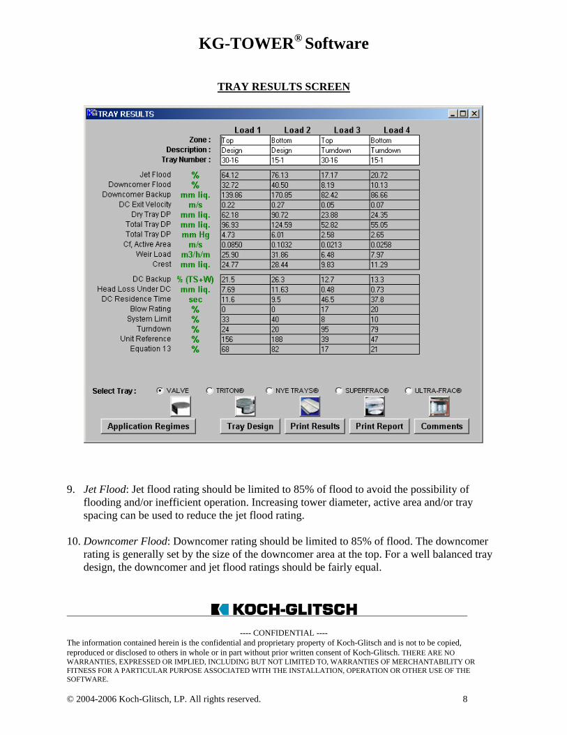
TRAY RESULTS SCREEN
9. Jet Flood: Jet flood rating should be limited to 85% of flood to avoid the possibility offlooding and/or inefficient operation. Increasing tower diameter, active area and/or trayspacing can be used to reduce the jet flood rating.
10. Downcomer Flood: Downcomer rating should be limited to 85% of flood. The downcomerrating is generally set by the size of the downcomer area at the top. For a well balanced traydesign, the downcomer and jet flood ratings should be fairly equal.
KG-TOWER® Software
---- CONFIDENTIAL ----The information contained herein is the confidential and proprietary property of Koch-Glitsch and is not to be copied,reproduced or disclosed to others in whole or in part without prior written consent of Koch-Glitsch. THERE ARE NOWARRANTIES, EXPRESSED OR IMPLIED, INCLUDING BUT NOT LIMITED TO, WARRANTIES OF MERCHANTABILITY ORFITNESS FOR A PARTICULAR PURPOSE ASSOCIATED WITH THE INSTALLATION, OPERATION OR OTHER USE OF THESOFTWARE.
© 2004-2006 Koch-Glitsch, LP. All rights reserved. 10
11. Downcomer Backup: The clear liquid downcomer backup is reported in both inchesof liquid and as a percentage of the tray spacing plus weir height. The clear liquid backupshould be limited to 40% of the tray spacing plus weir height for normal services. For highpressure, light hydrocarbon distillation services, the clear liquid backup should be limited to30-33% of the tray spacing plus weir height. The downcomer backup is dependent on thetray pressure drop and the clearance underthe downcomer.
12. DC Exit Velocity: The downcomer exit velocity is the liquid velocity as it flows horizontallythrough the downcomer clearance. This value should be limited to 1.5 ft/sec [0.46 m/s] forconventional valve tray designs. The downcomer exit velocity is most easily adjusted bychanging the downcomer clearance.
13. Dry Tray DP: The dry tray pressure drop is an intermediate term in calculating the total traypressure drop that does not include the effect of the liquid head. It can be used to provide arelative indication of vapor velocity through the valves. A good starting point for many traydesigns is a dry tray pressure drop of around 2 inches of hot liquid. As a rule of thumb, thedry tray pressure drop should be limited to 15% of the tray spacing when possible.
14. Total Tray DP: Many tray design methods do not set specific limits on the tray pressuredrop; however, a tray typically reaches flood at a pressure drop of around 8-10 mm Hg pertray. The tray pressure drop is also a very key component to downcomer hydraulics due to itsimpact on downcomer backup.
Note: Consistent with industry standards, the total tray pressure drop calculated byKG-TOWER software is comprised solely of the dry tray drop and the hydrostatic head ofliquid that exists on the tray when liquid is flowing across it. The KG-TOWER software-calculated total tray pressure drop does not include the vapor static head in the operatingcolumn (i.e. the weight of the vapor is excluded from the calculation). Vapor static head mustbe estimated by process engineers responsible for the total distillation system including theheat exchangers. Vapor static head can have an appreciable impact on the pressure differencebetween the top and the bottom of a distillation column. For example, in a demethanizer witha vapor density of 5 lb/ft3 and 24-inch tray spacings, the inclusion of the vapor static headcan cause the calculated top-to-bottom pressure difference to double.
15. Cf, Active Area: Cf or capacity factor is a commonly used, density-corrected vapor velocityterm on a per unit of active area basis.
KG-TOWER® Software
---- CONFIDENTIAL ----The information contained herein is the confidential and proprietary property of Koch-Glitsch and is not to be copied,reproduced or disclosed to others in whole or in part without prior written consent of Koch-Glitsch. THERE ARE NOWARRANTIES, EXPRESSED OR IMPLIED, INCLUDING BUT NOT LIMITED TO, WARRANTIES OF MERCHANTABILITY ORFITNESS FOR A PARTICULAR PURPOSE ASSOCIATED WITH THE INSTALLATION, OPERATION OR OTHER USE OF THESOFTWARE.
© 2004-2006 Koch-Glitsch, LP. All rights reserved. 11
16. Weir Load: The weir loading is generally used to determine the liquid loading of thetray. Although there is no specific design limit for weir loading, increased number offlow passes should be considered when the weir loading is greater than 100 – 120 gpm/ft[74.5 – 89.4 m3/h/m] in order to provide increased tray capacity. Trays have been designed insome large-tray-spacing cases with weir loadings greater than 200 gpm/ft [149 m3/h/m];however, consultation with a Koch-Glitsch design engineer is recommended when designingtrays for weir loadings greater than 140 gpm/ft [104.3 m3/h/m].
A minimum weir loading of 5 gpm/ft [3.7 m3/h/m] is recommended at turndown. Picketfence outlet weirs (or "weir blocks") can be added to increase the weir loading by specifyingan override to the calculated outlet weir length or specifying a percentage of the outlet weirto be blocked.
17. Crest: The crest is the theoretical height of clear liquid flowing over the outlet weir. It isimportant to remember that the liquid leaving the tray consists of drops, spray and slugs andnot a measurable height of clear liquid as this term might suggest.The liquid crest is directly associated with the weir loading. A minimum liquid crest of 0.25inches [6 mm] is recommended to ensure proper tray performance at low liquid rates.
18. Head Loss Under DC: The head loss under the downcomer is based on the downcomerclearance and the shape of the downcomer edge. Typically, the head loss should be designedsomewhere between 0.06 to 1.0 inches [1.5 to 25 mm]. The head loss can be adjusted bychanging the downcomer clearance or utilizing radius-tip downcomers.
19. DC Residence Time: The calculated residence time in the limiting downcomer is based on theliquid flow rate and the available volume of the downcomer. Downcomer residence time isnot typically used by Koch-Glitsch to determine proper downcomer sizing; however, thisparameter is used by some tray designers to size downcomers in foaming systems.
20. Blow Rating: The blow rating indicates the approach to a phase inversion condition, in whichthe liquid is blown into a fine spray (or "fluidized"), leaving the trayessentially dry (even though the spray is not necessarily carried to the tray above). The result is a loss of column efficiency due to gas bypassing and a shift in the limiting masstransfer resistance (from the gas side to the liquid side).
The blow rating is only applicable to trays operating in the spray regime and thus is reportedas zero for moderate to high liquid rate applications.
KG-TOWER® Software
---- CONFIDENTIAL ----The information contained herein is the confidential and proprietary property of Koch-Glitsch and is not to be copied,reproduced or disclosed to others in whole or in part without prior written consent of Koch-Glitsch. THERE ARE NOWARRANTIES, EXPRESSED OR IMPLIED, INCLUDING BUT NOT LIMITED TO, WARRANTIES OF MERCHANTABILITY ORFITNESS FOR A PARTICULAR PURPOSE ASSOCIATED WITH THE INSTALLATION, OPERATION OR OTHER USE OF THESOFTWARE.
© 2004-2006 Koch-Glitsch, LP. All rights reserved. 12
The blow rating should be held to a maximum of to 85% if possible. It can be reduced byincreasing the number of valves, adding weir blocks, and/or raising the outlet weir height.
21. System Limit: The system limit represents an ultimate column capacity limit which can not beexceeded by changing the tray design or increasing the tray spacing. It occurs when there issubstantial up-flow of liquid entrained relative to the total liquid flow and is a function of thedroplet sizes created at a certain surface tension and the terminal velocities of the liquiddroplets as determined by Stokes Law.
22. Turndown: The turndown is an approximation of the minimum vapor rate required forefficient tray activity (vapor and liquid contacting from movable valve units), expressed as apercent of the loads specified. This term applies only to moveable valves (not fixed valves)and is not to be confused with weepage .
If possible, valve trays should be designed for a turndown percentage of at least 50% atdesign rates (allowing a 2:1 turndown from the design rates). For the minimum rate cases, thecalculated turndown percentage should be less than or equal to 100%.
23. Unit Reference: Unit reference is the percentage of valves open at a given operatingcondition. This term serves a similar function of the turndown percentage (#24) and isapplicable to only moving valve units. The suggested minimum unit references are given intable 4.
Table 4: Recommended Minimum Unit Reference
Number of Flow Passes Minimum Unit Reference1 402 603 704 80
If the unit reference is less than the minimum recommended, the valve quantity should bereduced or consideration should be given to the use of two weights of valves.
26. Equation 13: Equation 13 is the conventional valve tray jet flood capacity model from Glitsch Bulletin 4900. It is reported as a convenience to those users that are familiar with this popular flooding model.
KG-TOWER® Software
---- CONFIDENTIAL ----The information contained herein is the confidential and proprietary property of Koch-Glitsch and is not to be copied,reproduced or disclosed to others in whole or in part without prior written consent of Koch-Glitsch. THERE ARE NOWARRANTIES, EXPRESSED OR IMPLIED, INCLUDING BUT NOT LIMITED TO, WARRANTIES OF MERCHANTABILITY ORFITNESS FOR A PARTICULAR PURPOSE ASSOCIATED WITH THE INSTALLATION, OPERATION OR OTHER USE OF THESOFTWARE.
© 2004-2006 Koch-Glitsch, LP. All rights reserved. 13
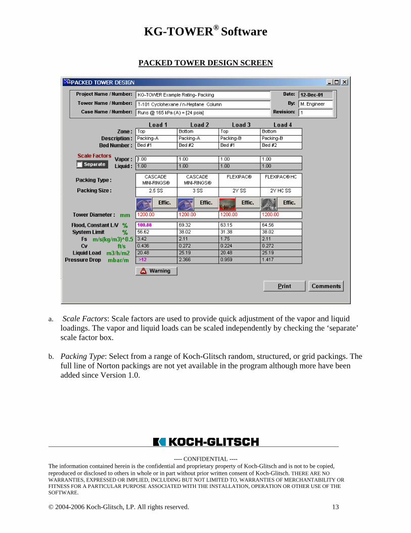
PACKED TOWER DESIGN SCREEN
a. Scale Factors: Scale factors are used to provide quick adjustment of the vapor and liquidloadings. The vapor and liquid loads can be scaled independently by checking the ‘separate’scale factor box.
b. Packing Type: Select from a range of Koch-Glitsch random, structured, or grid packings. Thefull line of Norton packings are not yet available in the program although more have beenadded since Version 1.0.
KG-TOWER® Software
---- CONFIDENTIAL ----The information contained herein is the confidential and proprietary property of Koch-Glitsch and is not to be copied,reproduced or disclosed to others in whole or in part without prior written consent of Koch-Glitsch. THERE ARE NOWARRANTIES, EXPRESSED OR IMPLIED, INCLUDING BUT NOT LIMITED TO, WARRANTIES OF MERCHANTABILITY ORFITNESS FOR A PARTICULAR PURPOSE ASSOCIATED WITH THE INSTALLATION, OPERATION OR OTHER USE OF THESOFTWARE.
© 2004-2006 Koch-Glitsch, LP. All rights reserved. 14
c. Tower Diameter: Input the inside diameter of the column. It is important to account for anylining, clad, or wall thickness – especially when rating very small packed columns.
When sizing a new column, it is also possible to enter the desired packing flood capacity andhave the program calculate the required column diameter (for a given packing size).
d. Flood, Constant L/V%: The calculated percentage of flood (based on a constant liquid/vaporratio) should be limited to 80% for most cases. For those systems where the liquid rate isheld constant, the flooding percentage may be reported on a constant liquid rate basis byselecting ‘flooding limit’ under the options menu.
e. Fs, Cv, and Liquid Load: These terms are used to provide a relative indication of the vaporand liquid loads in the tower. These are based on the total cross sectional area of the tower.No general design guidelines exists for these parameters; however, some specific guidelinesare used for certain packings and/or for specific applications based on commercialexperience.
f. Pressure Drop: The packing pressure drop is expressed per unit of vertical distance (feet ormeter) of packing height. Again, packing and application specific guidelines are used todetermine minimum and maximum acceptable pressure drop limits.
Please note that the pressure drop in packed towers should also take into account the pressuredrop across the packed bed internals (distributors, collectors, etc) which are not accountedfor in the packing pressure drop. In addition, the packing pressure does not include the vaporstatic head of vapor (see item #15 under tray hydraulic calculations for additional details).
KG-TOWER® Software
---- CONFIDENTIAL ----The information contained herein is the confidential and proprietary property of Koch-Glitsch and is not to be copied,reproduced or disclosed to others in whole or in part without prior written consent of Koch-Glitsch. THERE ARE NOWARRANTIES, EXPRESSED OR IMPLIED, INCLUDING BUT NOT LIMITED TO, WARRANTIES OF MERCHANTABILITY ORFITNESS FOR A PARTICULAR PURPOSE ASSOCIATED WITH THE INSTALLATION, OPERATION OR OTHER USE OF THESOFTWARE.
© 2004-2006 Koch-Glitsch, LP. All rights reserved. 15
KG-TOWER® Software
License Agreement (“Agreement”)
Upon agreement with these terms as evidenced by your choice of the “I AGREE” option below,Koch-Glitsch, LP and/or its affiliates (“Koch-Glitsch”) grants you a personal, non-exclusive,non-transferable, royalty-free license to use the KG-TOWER® software (“Software”). ThisLicense shall remain in effect until terminated by Koch-Glitsch or until automatic termination,which will occur upon the end of the license agreement or the violation of any of theseprovisions. The Software is the property of Koch-Glitsch and all rights to patents, copyrights,trademarks and trade secrets in the Software or any modification are, and shall be withoutlimitation, the property of Koch-Glitsch. Modification, alteration, translation, disassembling orcreation of derivative materials is strictly prohibited. Proprietary and/or copyright notices orlabels will not be removed for any reason. Koch-Glitsch provides the Software “AS IS” andoffers no warranty or guarantee of any kind as to the information provided in the Software,including but in no way limited to results arising from the use of the Software, the accuracy ofthe information derived from the Software, or for any other use, non-use or application of theSoftware, and you acknowledge and agree that you assume all liability under any and allapplicable laws in connection with your installation and use of the Software. THERE ARE NOWARRANTIES, EXPRESSED OR IMPLIED, INCLUDING BUT NOT LIMITED TO,WARRANTIES OF MERCHANTABILITY OR FITNESS FOR A PARTICULAR PURPOSEASSOCIATED WITH THE INSTALLATION, OPERATION OR OTHER USE OF THESOFTWARE. Koch-Glitsch shall have the right to modify the terms of this License or theSoftware at any time without notice. IN NO EVENT SHALL KOCH-GLITSCH BE LIABLEFOR ANY LOSS, DAMAGE, CLAIM, FINE, PENALTY OR ANY OTHER CLAIM,INCLUDING BUT NOT LIMITED TO CLAIMS FOR CONSEQUENTIAL, SPECIAL,GENERAL, INCIDENTAL, DIRECT, INDIRECT, PERSONAL INJURY OR PROPERTYDAMAGES, INCLUDING WITHOUT LIMIT LOSS OF PROFITS, REVENUES, OR OTHERECONOMIC LOSSES, ARISING FROM OR IN ANY WAY CONNECTED TO THEINSTALLATION, OPERATION OR USE OF THE SOFTWARE. This License shall begoverned by the Laws of the State of Kansas, and any dispute or claim pursuant to this Licenseshall be subject to the exclusive jurisdiction of the courts located in Wichita, Kansas, USA.
KG-TOWER®, Bi-FRAC®, MAX-FRAC®, TRITON®, SUPERFRAC®, ULTRA-FRAC®, SUPERFLUX®, andKOCH-GLITSCH® are registered trademarks of Koch-Glitsch, LP.