intuity™ conversant system - …pdf.textfiles.com/manuals/telecom-f-r/lucent conversant... ·...
TRANSCRIPT

585-313-108108647405January 2000Issue 2
Intuity™ CONVERSANT ® SystemVersion 7.0
MAP/40P Maintenance

Intuity™ CONVERSANT® System Version 7.0 MAP/40P Maintenance 585-313-108 Issue 2 January 2000 ii
Copyright and Legal Notices
Copyright Copyright © 2000 by Lucent Technologies.All rights reserved. Printed in the USA.
This material is protected by the copyright laws of the United States and other countries. It may not be reproduced, distributed, or altered in any fashion by any entity (either internal or external to Lucent Technologies), except in accordance with applicable agreements, contracts or licensing, without the express written consent of the Business Communications Systems (BCS) Global Learning Solutions (GLS) organization and the business management owner of the material.
Acknowledgment This document was prepared by the GLS organization of the BCS division of Lucent Technologies. Offices are located in Denver CO, Columbus OH, Middletown NJ, and Basking Ridge NJ, USA.
Trademarks Lucent Technologies has made every effort to supply the following trademark information about company names, products, and services mentioned in the Intuity CONVERSANT documentation library:
• Adobe Systems, Inc. — Trademarks: Adobe, Acrobat.
• AT&T — Registered trademarks: Truevoice.

Copyright and Legal Notices
Intuity™ CONVERSANT® System Version 7.0 MAP/40P Maintenance 585-313-108 Issue 2 January 2000 iii
• CLEO Communications — Trademarks: LINKix.
• Hayes Microcomputer Products, Inc. — Trademarks: Hayes, Smartmodem.
• Intel Corporation — Registered trademarks: Pentium.
• Interface Systems, Inc. — Trademarks: CLEO.
• International Business Machines Corporation — Registered trademarks: IBM, VTAM.
• Lucent Technologies — Registered trademarks: 5ESS, AUDIX, CONVERSANT, DEFINITY, Voice Power. Trademarks: FlexWord, Intuity, Lucent.
• Microsoft Corporation — Registered trademarks: Excel, Internet Explorer, Microsoft, MS, MS-DOS, Windows, Windows NT.
• Minnesota Mining and Manufacturing — Trademarks: 3M.
• Netscape Communications — Trademarks: Netscape Navigator.
• Novell, Inc. — Registered trademarks: Novell.
• Oracle Corporation — Trademarks: OBJECT*SQL, ORACLE, ORACLE*Terminal, PRO*C, SQL*FORMS, SQL*Menu, SQL*Net, SQL*Plus, SQL*ReportWriter.
• Phillips Screw Co. — Registered trademarks: Phillips.

Copyright and Legal Notices
Intuity™ CONVERSANT® System Version 7.0 MAP/40P Maintenance 585-313-108 Issue 2 January 2000 iv
• Santa Cruz Operation, Inc. — Registered trademarks: UnixWare.
• UNIX System Laboratories, Inc. — Registered trademarks: UNIX.
• Veritas Software Corporation — Trademarks: VERITAS.
• Xerox Corporation — Trademarks: Ethernet.
Limited Warranty Lucent Technologies provides a limited warranty on this product. Refer to the “Limited Use Software License Agreement” card provided with your package.
Lucent Technologies has determined that use of this electronic data delivery system cannot cause harm to an end user's computing system and will not assume any responsibility for problems that may arise with a user's computer system while accessing the data in these document.
Every effort has been made to make sure that this document is complete and accurate at the time of release, but information is subject to change.
United States FCC Compliance Information
Part 15: Class A statement. This equipment has been tested and found to comply with the limits for a Class A digital device, pursuant to Part 15 of the FCC Rules. These limits are designed to provide reasonable protection against harmful interference when the equipment is operated in a commercial environment. This equipment generates, uses, and can radiate radio-frequency energy and, if not installed and used in accordance with the instructions, may cause harmful interference to radio communications.

Copyright and Legal Notices
Intuity™ CONVERSANT® System Version 7.0 MAP/40P Maintenance 585-313-108 Issue 2 January 2000 v
Operation of this equipment in a residential area is likely to cause harmful interference, in which case the user will be required to correct the interference at his own expense.
Canadian Department of Communications (DOC) Interference Information
This digital apparatus does not exceed the Class A limits for radio noise emissions set out in the radio interference regulations of the Canadian Department of Communications.
Le Présent Appareil Nomérique n’émet pas de bruits radioélectriques dépassant les limites applicables aux appareils numériques de la class A préscrites dans le reglement sur le brouillage radioélectrique édicté par le ministére des Communications du Canada.
European Union Declaration of Conformity
Lucent Technologies Business Communications Systems declares that the Intuity™ CONVERSANT® System equipment specified in this document conforms to the referenced European Union (EU) Directives and Harmonized Standards listed below: EMC Directive 89/336/EEC Low-Voltage Directive 73/23/EEC. The “CE” mark affixed to the equipment means that it conforms to the above directives.
Telecom New Zealand Ltd Warning Notices
GENERAL WARNING: The grant of a Telepermit for any item of terminal equipment indicates that only Telecom has accepted that the item complies with minimum conditions for connection to its network. It indicates no endorsement of the product by Telecom, nor does it provide any sort of warranty. Above all, it provides no assurance that any item will work correctly

Copyright and Legal Notices
Intuity™ CONVERSANT® System Version 7.0 MAP/40P Maintenance 585-313-108 Issue 2 January 2000 vi
in all respects with other items of Telepermitted equipment of a different make or model, nor does it imply that any product is compatible with all of Telecom’s network services.
IMPORTANT NOTICE: Under power failure conditions, this device may not operate. Please ensure that a separate telephone, not dependent on local power, is available for emergency use.
AUTOMATIC RE-ATTEMPTS TO THE SAME NUMBER: Some parameters required for compliance with Telecom’s Telepermit requirements are dependent on the equipment (PC) associated with this device. The associated equipment shall be set to operate within the following limits for compliance with Telecom specifications:
• There shall be no more than 10 call attempts to the same number within any 30 minute period for any single manual call initiation, and,
• The equipment shall go on-hook for a period of not less than 30 seconds between the end of one attempts and the beginning of the next attempt.
AUTOMATIC CALLS TO DIFFERENT NUMBERS: Some parameters required for compliance with Telecom’s Telepermit requirements are dependent on the equipment (PC) associated with this device. In order to operate within the limits for compliance with Telecom specifications, the associated equipment shall be set to ensure that automatic calls to different numbers are spaced such that there is not less than 5 seconds between the end of one call attempt and the beginning of the next attempt.

Copyright and Legal Notices
Intuity™ CONVERSANT® System Version 7.0 MAP/40P Maintenance 585-313-108 Issue 2 January 2000 vii
USER INSTRUCTIONS (AUTOMATIC CALL SETUP): This equipment shall not be set up to make automatic calls to the Telecom "111" emergency service.
CALL ANSWERING (AUTOMATIC ANSWERING EQUIPMENT): Some parameters required for compliance with Telecom’s Telepermit requirements are dependent on the equipment (PC) associated with this device. In order to operate within the limits for compliance with Telecom specifications, the associated equipment shall be set to ensure that calls are answered between 3 and 30 seconds of receipt of ringing.
Toll Fraud Toll fraud is the unauthorized use of your telecommunications system by an unauthorized party, for example, persons other than your company’s employees, agents, subcontractors, or persons working on your company’s behalf. Note that there may be a risk of toll fraud associated with your telecommunications system and, if toll fraud occurs, it can result in substantial additional charges for your telecommunications services.
Your Responsibility for Your System’s Security
You and your system manager are responsible for the security of your system and for preventing unauthorized use. You are also responsible for reading all installation, instruction, and system administration documents provided with this product in order to fully understand the features that can introduce risk of toll fraud and the steps that can be taken to reduce that risk. Lucent Technologies does not warrant that this product is immune from or will

Copyright and Legal Notices
Intuity™ CONVERSANT® System Version 7.0 MAP/40P Maintenance 585-313-108 Issue 2 January 2000 viii
prevent unauthorized use of common-carrier telecommunication services or facilities accessed through or connected to it. Lucent Technologies will not be responsible for any charges that result from such unauthorized use.
Lucent Technologies Fraud Intervention and Corporate Security
If you suspect that you are being victimized by toll fraud and you need technical support or assistance, call the Lucent Technologies National Customer Care Center Toll Fraud Intervention Hotline at 1 800 643-2353.
Aside from whether immediate support is required, all toll fraud incidents involving Lucent products or services should be reported to Lucent Corporate Security at 1 800 821-8235. In addition to recording the incident, Lucent Corporate Security is available for consultation on security issues, investigation support, referral to law enforcement agencies, and educational programs.
Documentation Ordering Information
To order a document, contact the Lucent Technologies Publications Center and specify the 9-digit document number, the issue number, and the issue date.

Copyright and Legal Notices
Intuity™ CONVERSANT® System Version 7.0 MAP/40P Maintenance 585-313-108 Issue 2 January 2000 ix
Write, Call, or Fax
Lucent Technologies Publications Center2855 N. Franklin RoadIndianapolis, IN 46219
Voice 1 800 457-1235 International Voice 317 322-6791FAX 1 800 457-1764 International FAX 317 322-6699
World Wide Web
Use a web browser to reach one of the following sites. Click Documents and follow the instructions at the site.
• Organizations within Lucent Technologies
http://www.cic.lucent.com
• Lucent Technologies customers and others
http://www.lucentdocs.com
Standing Orders
You can be placed on a standing order list for this and other documents you may need. Standing order will enable you to automatically receive updated versions of individual documents or document sets, billed to account information that you provide. For more information on standing orders, or to be put on a list to receive future issues of this document, call or write the Lucent Technologies Publications Center (see Write, Call, or Fax (page ix)).

Contents
Intuity™ CONVERSANT® System Version 7.0 MAP/40P Maintenance 585-313-108 Issue 2 January 2000 x
Copyright and Legal Notices iiCopyright. . . . . . . . . . . . . . . . . . . . . . . . . . . . . . . . . . . . . . . . . . . . . . . . . . . . . . .iiAcknowledgment. . . . . . . . . . . . . . . . . . . . . . . . . . . . . . . . . . . . . . . . . . . . . . . . .iiTrademarks . . . . . . . . . . . . . . . . . . . . . . . . . . . . . . . . . . . . . . . . . . . . . . . . . . . . .iiLimited Warranty . . . . . . . . . . . . . . . . . . . . . . . . . . . . . . . . . . . . . . . . . . . . . . . . ivUnited States FCC Compliance Information . . . . . . . . . . . . . . . . . . . . . . . . . . . ivCanadian Department of Communications (DOC) Interference Information . . vEuropean Union Declaration of Conformity . . . . . . . . . . . . . . . . . . . . . . . . . . . vTelecom New Zealand Ltd Warning Notices . . . . . . . . . . . . . . . . . . . . . . . . . . . vToll Fraud. . . . . . . . . . . . . . . . . . . . . . . . . . . . . . . . . . . . . . . . . . . . . . . . . . . . . .viiDocumentation Ordering Information . . . . . . . . . . . . . . . . . . . . . . . . . . . . . . . viii
About This Book xxviOverview . . . . . . . . . . . . . . . . . . . . . . . . . . . . . . . . . . . . . . xxviIntended Audience . . . . . . . . . . . . . . . . . . . . . . . . . . . . . . . . . xxviiHow to Use This Book . . . . . . . . . . . . . . . . . . . . . . . . . . . . . . . xxvii
How This Book Is Organized. . . . . . . . . . . . . . . . . . . . . . . . . . . . . . . . . . . . . xxviiConventions Used in This Book . . . . . . . . . . . . . . . . . . . . . . . . . . xxix
Terminology. . . . . . . . . . . . . . . . . . . . . . . . . . . . . . . . . . . . . . . . . . . . . . . . . . .xxx

Contents
Intuity™ CONVERSANT® System Version 7.0 MAP/40P Maintenance 585-313-108 Issue 2 January 2000 xi
Keyboard and Telephone Keypad Representations . . . . . . . . . . . . . . . . . . xxxiiiCross References and Hypertext . . . . . . . . . . . . . . . . . . . . . . . . . . . . . . . . xxxivScreen Displays . . . . . . . . . . . . . . . . . . . . . . . . . . . . . . . . . . . . . . . . . . . . . . xxxvOther Typography . . . . . . . . . . . . . . . . . . . . . . . . . . . . . . . . . . . . . . . . . . . . xxxvi
Safety and Security Alert Labels. . . . . . . . . . . . . . . . . . . . . . . . . xxxviGetting Help . . . . . . . . . . . . . . . . . . . . . . . . . . . . . . . . . . . xxxviiTechnical Assistance. . . . . . . . . . . . . . . . . . . . . . . . . . . . . . . xxxviii
Web Site . . . . . . . . . . . . . . . . . . . . . . . . . . . . . . . . . . . . . . . . . . . . . . . . . . .xxxviiiContact Numbers . . . . . . . . . . . . . . . . . . . . . . . . . . . . . . . . . . . . . . . . . . . .xxxviii
Related Resources. . . . . . . . . . . . . . . . . . . . . . . . . . . . . . . . xxxixTraining . . . . . . . . . . . . . . . . . . . . . . . . . . . . . . . . . . . . . . . . . . . . . . . . . . . . xxxixDocumentation . . . . . . . . . . . . . . . . . . . . . . . . . . . . . . . . . . . . . . . . . . . . . . . . . xl
Using the CD-ROM Documentation . . . . . . . . . . . . . . . . . . . . . . . . . xliiSetting the Default Magnification . . . . . . . . . . . . . . . . . . . . . . . . . . . . . . . . . . xliiiAdjusting the Window Size . . . . . . . . . . . . . . . . . . . . . . . . . . . . . . . . . . . . . . . xliiiHiding and Displaying Bookmarks . . . . . . . . . . . . . . . . . . . . . . . . . . . . . . . . . xliiiUsing the Button Bar . . . . . . . . . . . . . . . . . . . . . . . . . . . . . . . . . . . . . . . . . . . . xliiiUsing Hypertext Links . . . . . . . . . . . . . . . . . . . . . . . . . . . . . . . . . . . . . . . . . . . xliiiNavigating with Double Arrow Keys . . . . . . . . . . . . . . . . . . . . . . . . . . . . . . . . xliiiSearching for Topics . . . . . . . . . . . . . . . . . . . . . . . . . . . . . . . . . . . . . . . . . . . . xlivDisplaying Figures. . . . . . . . . . . . . . . . . . . . . . . . . . . . . . . . . . . . . . . . . . . . . . xlivPrinting the Documentation. . . . . . . . . . . . . . . . . . . . . . . . . . . . . . . . . . . . . . . xliv
How To Comment on This Book . . . . . . . . . . . . . . . . . . . . . . . . . . .xlvComment Form . . . . . . . . . . . . . . . . . . . . . . . . . . . . . . . . . . . . . . . . . . . . . . . . xlvi

Contents
Intuity™ CONVERSANT® System Version 7.0 MAP/40P Maintenance 585-313-108 Issue 2 January 2000 xii
Contact Us Directly . . . . . . . . . . . . . . . . . . . . . . . . . . . . . . . . . . . . . . . . . . . . xlvii
1 Getting Inside the Computer 1Overview . . . . . . . . . . . . . . . . . . . . . . . . . . . . . . . . . . . . . . . 1Protecting Against Damage from Electrostatic Discharge . . . . . . . . . . . . . 2Removing Power from the MAP/40P. . . . . . . . . . . . . . . . . . . . . . . . . 6Removing the Dress Cover . . . . . . . . . . . . . . . . . . . . . . . . . . . . . 9Replacing the Dress Cover . . . . . . . . . . . . . . . . . . . . . . . . . . . . . 10Restoring Power to the MAP/40P . . . . . . . . . . . . . . . . . . . . . . . . . . 10
2 Installing or Replacing Circuit Cards 11Overview . . . . . . . . . . . . . . . . . . . . . . . . . . . . . . . . . . . . . . . 11General Procedures . . . . . . . . . . . . . . . . . . . . . . . . . . . . . . . . . 12
Removing a Circuit Card . . . . . . . . . . . . . . . . . . . . . . . . . . . . . . . . . . . . . . . . . . . 12Installing a Circuit Card . . . . . . . . . . . . . . . . . . . . . . . . . . . . . . . . . . . . . . . . . . . . 14
Settings for Optional Circuit Cards. . . . . . . . . . . . . . . . . . . . . . . . . . 16Tip/Ring Circuit Cards . . . . . . . . . . . . . . . . . . . . . . . . . . . . . . . . . . . . . . . . . . . . . 17
IVP6-IA (AYC29) Circuit Card . . . . . . . . . . . . . . . . . . . . . . . . . . . . . . . . . . . . . 20IVC6 (AYC10) Circuit Card . . . . . . . . . . . . . . . . . . . . . . . . . . . . . . . . . . . . . . . 22NGTR (AYC30) Circuit Card . . . . . . . . . . . . . . . . . . . . . . . . . . . . . . . . . . . . . . 24Installing the Tip/Ring Circuit Card Driver . . . . . . . . . . . . . . . . . . . . . . . . . . . . 27
E1/T1 Circuit Card . . . . . . . . . . . . . . . . . . . . . . . . . . . . . . . . . . . . . . . . . . . . . . . . 29Jumper Settings . . . . . . . . . . . . . . . . . . . . . . . . . . . . . . . . . . . . . . . . . . . . . . . 31

Contents
Intuity™ CONVERSANT® System Version 7.0 MAP/40P Maintenance 585-313-108 Issue 2 January 2000 xiii
Switch Settings . . . . . . . . . . . . . . . . . . . . . . . . . . . . . . . . . . . . . . . . . . . . . . . . 31Installing the E1/T1 Circuit Card Driver. . . . . . . . . . . . . . . . . . . . . . . . . . . . . . 34
Speech and Signal Processor (AYC43) Circuit Card . . . . . . . . . . . . . . . . . . . . . . 37Jumper Settings . . . . . . . . . . . . . . . . . . . . . . . . . . . . . . . . . . . . . . . . . . . . . . . 38Switch Settings . . . . . . . . . . . . . . . . . . . . . . . . . . . . . . . . . . . . . . . . . . . . . . . . 39Memory . . . . . . . . . . . . . . . . . . . . . . . . . . . . . . . . . . . . . . . . . . . . . . . . . . . . . . 41Installing the ASP Driver Package . . . . . . . . . . . . . . . . . . . . . . . . . . . . . . . . . 41
PCI Ethernet LAN Circuit Cards . . . . . . . . . . . . . . . . . . . . . . . . . . . . . . . . . . . . . 44SMC8432 Circuit Card . . . . . . . . . . . . . . . . . . . . . . . . . . . . . . . . . . . . . . . . . . 45SMC9332 Circuit Card . . . . . . . . . . . . . . . . . . . . . . . . . . . . . . . . . . . . . . . . . . 46Installing a PCI LAN Circuit Card . . . . . . . . . . . . . . . . . . . . . . . . . . . . . . . . . . 47
Replacing a PCI LAN Circuit Card. . . . . . . . . . . . . . . . . . . . . . . . . . . . . . . . . . . . 53Token Ring Circuit Card. . . . . . . . . . . . . . . . . . . . . . . . . . . . . . . . . . . . . . . . . . . . 53
IBM Turbo 16/4 . . . . . . . . . . . . . . . . . . . . . . . . . . . . . . . . . . . . . . . . . . . . . . . . 54Installing the Token Ring Driver . . . . . . . . . . . . . . . . . . . . . . . . . . . . . . . . . . . 63
Asynchronous SuperSerial Card . . . . . . . . . . . . . . . . . . . . . . . . . . . . . . . . . . . . . 68Installing the Asynchronous SuperSerial Card Driver . . . . . . . . . . . . . . . . . . . 70
FIFO/SIB Synchronous Host Circuit Card . . . . . . . . . . . . . . . . . . . . . . . . . . . . . . 74Jumper Settings . . . . . . . . . . . . . . . . . . . . . . . . . . . . . . . . . . . . . . . . . . . . . . . 76Switch Settings . . . . . . . . . . . . . . . . . . . . . . . . . . . . . . . . . . . . . . . . . . . . . . . . 77
Standard Circuit Cards. . . . . . . . . . . . . . . . . . . . . . . . . . . . . . . . 79P5 200 MHz CPU Circuit Card . . . . . . . . . . . . . . . . . . . . . . . . . . . . . . . . . . . . . . 80
Setting the Resource Options . . . . . . . . . . . . . . . . . . . . . . . . . . . . . . . . . . . . . 82Placing the P5 200 MHz CPU Circuit Card in the MAP/40P. . . . . . . . . . . . . . 83Verifying the Parameter Settings. . . . . . . . . . . . . . . . . . . . . . . . . . . . . . . . . . . 87
Contents
Intuity™ CONVERSANT® System Version 7.0 MAP/40P Maintenance 585-313-108 Issue 2 January 2000 xiv
CMOS Parameter Settings. . . . . . . . . . . . . . . . . . . . . . . . . . . . . . 92Video Controller Circuit Cards . . . . . . . . . . . . . . . . . . . . . . . . . . . . . . . . . . . . . . 104
Remote Maintenance Circuit Card . . . . . . . . . . . . . . . . . . . . . . . . . 107Types of Remote Maintenance Circuit Cards . . . . . . . . . . . . . . . . . . . . . . . . 109Setting the Resource Options . . . . . . . . . . . . . . . . . . . . . . . . . . . . . . . . . . . . 112Inserting the Remote Maintenance Circuit Card . . . . . . . . . . . . . . . . . . . . . . 112Installing the Remote Maintenance Circuit Card Software Package. . . . . . . 113
3 Replacing the Hard Disk Drive 116Overview . . . . . . . . . . . . . . . . . . . . . . . . . . . . . . . . . . . . . . 116Identifying a Failed Hard Disk Drive . . . . . . . . . . . . . . . . . . . . . . . . 117
Hard Disk Drive Contents of the Hard Disk Drives in a Two-Drive System . . . . 117Identifying a Hard Disk Drive 0 Failure in a Nonmirrored or
Single-Disk System. . . . . . . . . . . . . . . . . . . . . . . . . . . . . . . . . . . . . . . . . . . . . 118Identifying a Hard Disk Drive 1 Failure in a Nonmirrored System . . . . . . . . . . . 119Identifying a Hard Disk Drive Failure in a Mirrored System . . . . . . . . . . . . . . . . 119
Replacing a Hard Disk Drive . . . . . . . . . . . . . . . . . . . . . . . . . . . . 120Hard Disk Drive Removal. . . . . . . . . . . . . . . . . . . . . . . . . . . . . . . . . . . . . . . . . . 122
Removing the Lucent Intuity CONVERSANT System from Service . . . . . . . 122Accessing A Hard Disk Drive . . . . . . . . . . . . . . . . . . . . . . . . . . . . . . . . . . . . 123Extracting Hard Disk Drive . . . . . . . . . . . . . . . . . . . . . . . . . . . . . . . . . . . . . . 123
Hard Disk Drive Installation . . . . . . . . . . . . . . . . . . . . . . . . . . . . . . . . . . . . . . . . 124Inserting A Hard Disk Drive. . . . . . . . . . . . . . . . . . . . . . . . . . . . . . . . . . . . . . 125
Replacing Hard Disk Drive 0 . . . . . . . . . . . . . . . . . . . . . . . . . . . . 126

Contents
Intuity™ CONVERSANT® System Version 7.0 MAP/40P Maintenance 585-313-108 Issue 2 January 2000 xv
Replacing Hard Disk Drive 0 (Nonmirrored or Single-Disk System) . . . . . . . . . 126Replacing the Hard Disk Drive . . . . . . . . . . . . . . . . . . . . . . . . . . . . . . . . . . . 126Restoring the Intuity CONVERSANT System . . . . . . . . . . . . . . . . . . . . . . . . 127
Replacing Hard Disk Drive 0 (Mirrored System) . . . . . . . . . . . . . . . . . . . . . . . . 128Replacing the Hard Disk Drive . . . . . . . . . . . . . . . . . . . . . . . . . . . . . . . . . . . 128Restoring the Intuity CONVERSANT System . . . . . . . . . . . . . . . . . . . . . . . . 128
Replacing Hard Disk Drive 1 . . . . . . . . . . . . . . . . . . . . . . . . . . . . 134Software and Hardware Procedures for Replacing Hard Disk Drive 1
(Nonmirrored System). . . . . . . . . . . . . . . . . . . . . . . . . . . . . . . . . . . . . . . . . . . 135Replacing the Hard Disk Drive . . . . . . . . . . . . . . . . . . . . . . . . . . . . . . . . . . . 135Restoring the Intuity CONVERSANT System . . . . . . . . . . . . . . . . . . . . . . . . 135
Software and Hardware Procedures for Replacing Hard Disk Drive 1(Mirrored System) . . . . . . . . . . . . . . . . . . . . . . . . . . . . . . . . . . . . . . . . . . . . . . 137Replacing the Hard Disk Drive . . . . . . . . . . . . . . . . . . . . . . . . . . . . . . . . . . . 138Restoring the Intuity CONVERSANT System . . . . . . . . . . . . . . . . . . . . . . . . 138
Adding a Hard Disk Drive . . . . . . . . . . . . . . . . . . . . . . . . . . . . . 142Adding a Hard Disk Drive to a System for Mirroring . . . . . . . . . . . . . . . . . . . . . 143Adding a Hard Disk Drive to a System for Speech Storage . . . . . . . . . . . . . . . 149Moving the Speech to the Speech Disk. . . . . . . . . . . . . . . . . . . . . . . . . . . . . . . 152
Cleaning a Hard Disk Drive . . . . . . . . . . . . . . . . . . . . . . . . . . . . 153Using the fdisk Command . . . . . . . . . . . . . . . . . . . . . . . . . . . . . . . . . . . . . . . . . 153Low-Level Formatting the Hard Disk Drive . . . . . . . . . . . . . . . . . . . . . . . . . . . . 156
Low-Level Formatting with a P5 200 MHz CPU Circuit Card . . . . . . . . . . . . 156Mirroring . . . . . . . . . . . . . . . . . . . . . . . . . . . . . . . . . . . . . . 159

Contents
Intuity™ CONVERSANT® System Version 7.0 MAP/40P Maintenance 585-313-108 Issue 2 January 2000 xvi
Establishing Mirroring . . . . . . . . . . . . . . . . . . . . . . . . . . . . . . . . . . . . . . . . . . . . 159Removing Mirroring . . . . . . . . . . . . . . . . . . . . . . . . . . . . . . . . . . . . . . . . . . . . . . 164
Disk Reuse. . . . . . . . . . . . . . . . . . . . . . . . . . . . . . . . . . . . . 165Reusing for Mirroring . . . . . . . . . . . . . . . . . . . . . . . . . . . . . . . . . . . . . . . . . . . . . 165Reusing for Speech . . . . . . . . . . . . . . . . . . . . . . . . . . . . . . . . . . . . . . . . . . . . . . 165
4 Replacing Other Components 167Overview . . . . . . . . . . . . . . . . . . . . . . . . . . . . . . . . . . . . . . 167Replacing the Electromagnetic Interference Reduction Components . . . . . . . 168
General Toroid and Ferrite Installation Guidelines. . . . . . . . . . . . . . . . . . . . . . . 170Installing a Ferrite . . . . . . . . . . . . . . . . . . . . . . . . . . . . . . . . . . . . . . . . . . . . . . . 171Installing a Toroid on the MAP/40P . . . . . . . . . . . . . . . . . . . . . . . . . . . . . . . . . . 175
Replacing the Backplane . . . . . . . . . . . . . . . . . . . . . . . . . . . . . 177Removing the Backplane. . . . . . . . . . . . . . . . . . . . . . . . . . . . . . . . . . . . . . . . . . 180Installing the Backplane. . . . . . . . . . . . . . . . . . . . . . . . . . . . . . . . . . . . . . . . . . . 181
Replacing Cables . . . . . . . . . . . . . . . . . . . . . . . . . . . . . . . . . 184Replacing the Diskette Cable. . . . . . . . . . . . . . . . . . . . . . . . . . . . . . . . . . . . . . . 184
Removing the Diskette Cable . . . . . . . . . . . . . . . . . . . . . . . . . . . . . . . . . . . . 186Installing a Diskette Cable. . . . . . . . . . . . . . . . . . . . . . . . . . . . . . . . . . . . . . . 188
Replacing the Keyboard Cable . . . . . . . . . . . . . . . . . . . . . . . . . . . . . . . . . . . . . 188Removing the Keyboard Cable . . . . . . . . . . . . . . . . . . . . . . . . . . . . . . . . . . . 190Installing a Keyboard Cable . . . . . . . . . . . . . . . . . . . . . . . . . . . . . . . . . . . . . 193
Replacing the SCSI Cable . . . . . . . . . . . . . . . . . . . . . . . . . . . . . . . . . . . . . . . . . 193

Contents
Intuity™ CONVERSANT® System Version 7.0 MAP/40P Maintenance 585-313-108 Issue 2 January 2000 xvii
Removing the SCSI Cable . . . . . . . . . . . . . . . . . . . . . . . . . . . . . . . . . . . . . . 195Installing a SCSI Cable . . . . . . . . . . . . . . . . . . . . . . . . . . . . . . . . . . . . . . . . . 196
Replacing the Cartridge Tape Drive . . . . . . . . . . . . . . . . . . . . . . . . 197Removing the Cartridge Tape Drive. . . . . . . . . . . . . . . . . . . . . . . . . . . . . . . . . . 198Installing the Cartridge Tape Drive . . . . . . . . . . . . . . . . . . . . . . . . . . . . . . . . . . 200
Replacing the Circuit Card Cage Fan . . . . . . . . . . . . . . . . . . . . . . . 202Removing a Circuit Card Cage Fan . . . . . . . . . . . . . . . . . . . . . . . . . . . . . . . . . . 203Installing a Circuit Card Cage Fan . . . . . . . . . . . . . . . . . . . . . . . . . . . . . . . . . . . 205
Replacing the Diskette Drive. . . . . . . . . . . . . . . . . . . . . . . . . . . . 206Removing the Diskette Drive . . . . . . . . . . . . . . . . . . . . . . . . . . . . . . . . . . . . . . . 207Installing a Diskette Drive . . . . . . . . . . . . . . . . . . . . . . . . . . . . . . . . . . . . . . . . . 211
Replacing the Filter . . . . . . . . . . . . . . . . . . . . . . . . . . . . . . . . 215Removing the Filter . . . . . . . . . . . . . . . . . . . . . . . . . . . . . . . . . . . . . . . . . . . . . . 217Cleaning the Filter . . . . . . . . . . . . . . . . . . . . . . . . . . . . . . . . . . . . . . . . . . . . . . . 217Installing the Filter . . . . . . . . . . . . . . . . . . . . . . . . . . . . . . . . . . . . . . . . . . . . . . . 217
Replacing Memory Modules . . . . . . . . . . . . . . . . . . . . . . . . . . . . 218Memory and SIMM Description . . . . . . . . . . . . . . . . . . . . . . . . . . . . . . . . . . . . . 219
Installation Rules. . . . . . . . . . . . . . . . . . . . . . . . . . . . . . . . . . . . . . . . . . . . . . 219SIMMs Configurations. . . . . . . . . . . . . . . . . . . . . . . . . . . . . . . . . . . . . . . . . . 220
Identifying a Damaged SIMM . . . . . . . . . . . . . . . . . . . . . . . . . . . . . . . . . . . . . . 221Checking for Proper SIMM Seating. . . . . . . . . . . . . . . . . . . . . . . . . . . . . . . . 222Checking for Defective SIMMs . . . . . . . . . . . . . . . . . . . . . . . . . . . . . . . . . . . 223
Removing SIMMs . . . . . . . . . . . . . . . . . . . . . . . . . . . . . . . . . . . . . . . . . . . . . . . 225Installing SIMMs . . . . . . . . . . . . . . . . . . . . . . . . . . . . . . . . . . . . . . . . . . . . . . . . 226

Contents
Intuity™ CONVERSANT® System Version 7.0 MAP/40P Maintenance 585-313-108 Issue 2 January 2000 xviii
Replacing the Power ON/OFF Switch . . . . . . . . . . . . . . . . . . . . . . . 229Removing the Power ON/OFF Switch . . . . . . . . . . . . . . . . . . . . . . . . . . . . . . . . 229
Replacing the Power Supply . . . . . . . . . . . . . . . . . . . . . . . . . . . . 231Removing the Power Supply . . . . . . . . . . . . . . . . . . . . . . . . . . . . . . . . . . . . . . . 231Installing a Power Supply. . . . . . . . . . . . . . . . . . . . . . . . . . . . . . . . . . . . . . . . . . 235
Replacing a Terminator SIP . . . . . . . . . . . . . . . . . . . . . . . . . . . . 237
5 Installing the Tip/Ring Distribution Hardware 239Overview . . . . . . . . . . . . . . . . . . . . . . . . . . . . . . . . . . . . . . 239Capacity . . . . . . . . . . . . . . . . . . . . . . . . . . . . . . . . . . . . . . 239Types of Tip/Ring Distribution Hardware. . . . . . . . . . . . . . . . . . . . . . 240
Tip/Ring Distribution Hardware with a 356B Adapter . . . . . . . . . . . . . . . . . . . . 240Tip/Ring Distribution Hardware without a 356B Adapter . . . . . . . . . . . . . . . . . . 242
Installing and Connecting the Tip/Ring DistributionHardware with the 356B Adapter . . . . . . . . . . . . . . . . . . . . . . . . . 244
Installing the Tip/Ring Distribution Hardware with the 356B Adapter . . . . . . . . 244Connecting the Tip/Ring Distribution Hardware
with the 356B Adapter. . . . . . . . . . . . . . . . . . . . . . . . . . . . . . . . . . . . . . . . . . . 247Installing and Connecting the Tip/Ring Distribution
Hardware without the 356B Adapter . . . . . . . . . . . . . . . . . . . . . . . 247Installing the Tip/Ring Distribution Hardware without the 356B Adapter . . . . . . 248Connecting the Tip/Ring Distribution Hardware
without the 356B Adapter . . . . . . . . . . . . . . . . . . . . . . . . . . . . . . . . . . . . . . . . 248

Contents
Intuity™ CONVERSANT® System Version 7.0 MAP/40P Maintenance 585-313-108 Issue 2 January 2000 xix
Completing the Installation. . . . . . . . . . . . . . . . . . . . . . . . . . . . . 251
6 Installing Base System Software 252Overview . . . . . . . . . . . . . . . . . . . . . . . . . . . . . . . . . . . . . . 252Installing Base System Software. . . . . . . . . . . . . . . . . . . . . . . . . . 253
Beginning the UnixWare Installation . . . . . . . . . . . . . . . . . . . . . . . . . . . . . . . . . 253Setting Up the UnixWare Environment . . . . . . . . . . . . . . . . . . . . . . . . . . . . . . . 257Initializing the Hard Disk Drives . . . . . . . . . . . . . . . . . . . . . . . . . . . . . . . . . . . . . 264Transferring the UnixWare Files. . . . . . . . . . . . . . . . . . . . . . . . . . . . . . . . . . . . . 276Installing the Application Server . . . . . . . . . . . . . . . . . . . . . . . . . . . . . . . . . . . . 278
Activating the Volume Manager . . . . . . . . . . . . . . . . . . . . . . . . . . 280Installing the LAN Card Driver Package . . . . . . . . . . . . . . . . . . . . . . 281Setting up the Monitor . . . . . . . . . . . . . . . . . . . . . . . . . . . . . . . 281Initializing the Mouse. . . . . . . . . . . . . . . . . . . . . . . . . . . . . . . . 286Testing the Mouse . . . . . . . . . . . . . . . . . . . . . . . . . . . . . . . . . 290
7 Installing the Intuity CONVERSANT System Software 291Overview . . . . . . . . . . . . . . . . . . . . . . . . . . . . . . . . . . . . . . 291Installing the Intuity CONVERSANT Base Software Set. . . . . . . . . . . . . . 292Installing the TCP/IP Packages . . . . . . . . . . . . . . . . . . . . . . . . . . 304

Contents
Intuity™ CONVERSANT® System Version 7.0 MAP/40P Maintenance 585-313-108 Issue 2 January 2000 xx
8 Installing the Optional Feature Software 306Overview . . . . . . . . . . . . . . . . . . . . . . . . . . . . . . . . . . . . . . 306Installing Software Packages Using the Unix Management Screens . . . . . . . 307Installing the Hardware Resource Allocator Package . . . . . . . . . . . . . . . 309Installing the Asynchronous Host Toolkit. . . . . . . . . . . . . . . . . . . . . . 312
Installing the ASYNC_TEST Transaction Script Builder Backup . . . . . . . . . . . . 315Installing the ASYNC_TEST Speech Script Builder Backup . . . . . . . . . . . . . . . 317
Installing the Adjunct/Switch Application Interface Packages . . . . . . . . . . . 319Installing the CALLVISOR PC ISDN Package . . . . . . . . . . . . . . . . . . . . . . . . . . 319Installing the CALLVISOR PC LAN Gateway Package . . . . . . . . . . . . . . . . . . . 322Installing the CALLVISOR PC ASAI Package . . . . . . . . . . . . . . . . . . . . . . . . . . 324Installing the Adjunct/Switch Application Interface Package . . . . . . . . . . . . . . . 327
Installing the Analog Switch Interface Package . . . . . . . . . . . . . . . . . . 331Installing the Backup/Restore Utility . . . . . . . . . . . . . . . . . . . . . . . . 333Installing the Call Bridge Application Package. . . . . . . . . . . . . . . . . . . 335Installing the Call Classification Analysis Package . . . . . . . . . . . . . . . . 337Installing the Data Collection Toolkit . . . . . . . . . . . . . . . . . . . . . . . . 340Installing the Dial Pulse Recognition Package. . . . . . . . . . . . . . . . . . . 343Installing the Enhanced Basic Speech Package. . . . . . . . . . . . . . . . . . 345Installing the FlexWord Speech Recognition Package. . . . . . . . . . . . . . . 347
Installing the ASP Driver . . . . . . . . . . . . . . . . . . . . . . . . . . . . . . . . . . . . . . . . . . 347Installing FlexWord Recognition - Base . . . . . . . . . . . . . . . . . . . . . . . . . . . . . . . 348

Contents
Intuity™ CONVERSANT® System Version 7.0 MAP/40P Maintenance 585-313-108 Issue 2 January 2000 xxi
Installing FlexWord Recognition - U.S. English . . . . . . . . . . . . . . . . . . . . . . . . . 350Installing the FlexWord Toolkit Package . . . . . . . . . . . . . . . . . . . . . . 355Installing the Form Filler Application . . . . . . . . . . . . . . . . . . . . . . . . 357Installing the Graphical Speech Editor Package . . . . . . . . . . . . . . . . . . 361Installing the LAN Adapter Setup Program . . . . . . . . . . . . . . . . . . . . 363Installing the CLEO Packages . . . . . . . . . . . . . . . . . . . . . . . . . . . 365
Installing the cleo_tkrn Package . . . . . . . . . . . . . . . . . . . . . . . . . . . . . . . . . . . . 367Installing the cleo_sib Package . . . . . . . . . . . . . . . . . . . . . . . . . . . . . . . . . . . . . 369Installing the cleo_sna_1281u Package . . . . . . . . . . . . . . . . . . . . . . . . . . . . . . 375Installing the cleo_3270 Package . . . . . . . . . . . . . . . . . . . . . . . . . . . . . . . . . . . 378Installing the cleo_mgmt Package . . . . . . . . . . . . . . . . . . . . . . . . . . . . . . . . . . . 381Installing the cleo_netman Package . . . . . . . . . . . . . . . . . . . . . . . . . . . . . . . . . 383Installing the cleo_HTE Package . . . . . . . . . . . . . . . . . . . . . . . . . . . . . . . . . . . . 386Completing the Installation . . . . . . . . . . . . . . . . . . . . . . . . . . . . . . . . . . . . . . . . 388
Installing the Host Packages. . . . . . . . . . . . . . . . . . . . . . . . . . . . 389Installing the Synchronous Host Interface Package . . . . . . . . . . . . . . . . . . . . . 389Installing the 3270 Enhanced File Transfer Package. . . . . . . . . . . . . . . . . . . . . 391Installing the NetView Alarm Interface Package . . . . . . . . . . . . . . . . . . . . . . . . 393
Installing the ORACLE Development Packages . . . . . . . . . . . . . . . . . . 395Package List . . . . . . . . . . . . . . . . . . . . . . . . . . . . . . . . . . . . . . . . . . . . . . . . . . . 396Installation Requirements . . . . . . . . . . . . . . . . . . . . . . . . . . . . . . . . . . . . . . . . . 397Procedures . . . . . . . . . . . . . . . . . . . . . . . . . . . . . . . . . . . . . . . . . . . . . . . . . . . . 397
Increasing ORACLE File System . . . . . . . . . . . . . . . . . . . . . . . . . . . . . . . . . 397Creating a Temporary File System . . . . . . . . . . . . . . . . . . . . . . . . . . . . . . . . 398

Contents
Intuity™ CONVERSANT® System Version 7.0 MAP/40P Maintenance 585-313-108 Issue 2 January 2000 xxii
Installing the ORACLE 7 Pro*C Package . . . . . . . . . . . . . . . . . . . . . . . . . . . 398Installing the ORACLE Developer 2000 Toolkit . . . . . . . . . . . . . . . . . . . . . . . 400
Post Installation Setup . . . . . . . . . . . . . . . . . . . . . . . . . . . . . . . 407Installing the ORACLE 7 Patch 19 . . . . . . . . . . . . . . . . . . . . . . . . . . . . . . . . 408Completing Installation . . . . . . . . . . . . . . . . . . . . . . . . . . . . . . . . . . . . . . . . . 409
Installing the ORACLE SQL*Net TCP/IP Package. . . . . . . . . . . . . . . . . 409Installing the Primary Rate Interface Packages . . . . . . . . . . . . . . . . . . 412
Installing the ISDN Primary Rate Interface Package . . . . . . . . . . . . . . . . . . . . . 412Installing the Advanced Primary Rate Interface Package . . . . . . . . . . . . . . . . . 415
Installing the Script Builder Package. . . . . . . . . . . . . . . . . . . . . . . . 417Installing the Script Builder FAX Actions Package . . . . . . . . . . . . . . . . . 421Installing the Unix Management Screens Package . . . . . . . . . . . . . . . . 429Installing T1 Packages . . . . . . . . . . . . . . . . . . . . . . . . . . . . . . . 431
Installing the Line Side T1 Interface Packages . . . . . . . . . . . . . . . . . . . . . . . . . 431Installing the Line Side T1 Interface Package - Definity . . . . . . . . . . . . . . . . 431Installing the Line Side T1 Interface Package - Galaxy. . . . . . . . . . . . . . . . . 434
Installing the T1 E&M Package . . . . . . . . . . . . . . . . . . . . . . . . . . . . . . . . . . . . . 436Installing the Text To Speech Package. . . . . . . . . . . . . . . . . . . . . . . 439Installing the WholeWord Recognition Packages . . . . . . . . . . . . . . . . . 446
Installing the WholeWord Recognition Base Package. . . . . . . . . . . . . . . . . . . . 446Installing the WholeWord Recognition Language Package . . . . . . . . . . . . . . . . 448
Installing the Feature Test Script Package . . . . . . . . . . . . . . . . . . . . . 450Installing the Universal Call ID Package . . . . . . . . . . . . . . . . . . . . . . 455

Contents
Intuity™ CONVERSANT® System Version 7.0 MAP/40P Maintenance 585-313-108 Issue 2 January 2000 xxiii
Installing the SNMP Emanate Agent Package. . . . . . . . . . . . . . . . . . . 457Removing Software Packages . . . . . . . . . . . . . . . . . . . . . . . . . . . 459
Using the Command Line . . . . . . . . . . . . . . . . . . . . . . . . . . . . . . . . . . . . . . . . . 460Using the Intuity CONVERSANT Screens. . . . . . . . . . . . . . . . . . . . . . . . . . . . . 462
Appendix A: System Configuration 465Overview . . . . . . . . . . . . . . . . . . . . . . . . . . . . . . . . . . . . . . 465Component Assignments . . . . . . . . . . . . . . . . . . . . . . . . . . . . . 466Operating the Hardware Resource Allocator . . . . . . . . . . . . . . . . . . . 468
Adding Hardware to an Existing Configuration . . . . . . . . . . . . . . . . . . . . . . . . . 468Removing Hardware from an Existing Configuration . . . . . . . . . . . . . . . . . . . . . 473Specifying a New Configuration. . . . . . . . . . . . . . . . . . . . . . . . . . . . . . . . . . . . . 477Saving a Configuration. . . . . . . . . . . . . . . . . . . . . . . . . . . . . . . . . . . . . . . . . . . . 482Viewing a Configuration. . . . . . . . . . . . . . . . . . . . . . . . . . . . . . . . . . . . . . . . . . . 484
Viewing a Successful Configuration . . . . . . . . . . . . . . . . . . . . . . . . . . . . . . . 484Viewing an Unsuccessful Configuration . . . . . . . . . . . . . . . . . . . . . . . . . . . . 487Viewing a Dated Configuration . . . . . . . . . . . . . . . . . . . . . . . . . . . . . . . . . . . 487
Comparing a Configuration . . . . . . . . . . . . . . . . . . . . . . . . . . . . . . . . . . . . . . . . 489Presetting Hardware Resources . . . . . . . . . . . . . . . . . . . . . . . . . . . . . . . . . . . . 489
Configuration Device Data . . . . . . . . . . . . . . . . . . . . . . . . . . . . . 492The show_devices Command . . . . . . . . . . . . . . . . . . . . . . . . . . . . . . . . . . . . . . 492

Contents
Intuity™ CONVERSANT® System Version 7.0 MAP/40P Maintenance 585-313-108 Issue 2 January 2000 xxiv
Appendix B: Component Ordering Numbers 493Overview . . . . . . . . . . . . . . . . . . . . . . . . . . . . . . . . . . . . . . 493Component Ordering Numbers . . . . . . . . . . . . . . . . . . . . . . . . . . 494
Appendix C: How to Build a System Using This Book 509Overview . . . . . . . . . . . . . . . . . . . . . . . . . . . . . . . . . . . . . . 509Checklist for Building a System . . . . . . . . . . . . . . . . . . . . . . . . . . 510
Appendix D: Disaster Recovery Checklists 512Disaster Recovery Checklists . . . . . . . . . . . . . . . . . . . . . . . . . . . 512
Checklist for Software Reloading on Nonmirrored Intuity CONVERSANTSystems with Existing Hard Disk Drives . . . . . . . . . . . . . . . . . . . . . . . . . . . . . 513
Checklist for Intuity CONVERSANT Systems with All New Hard Disk Drives . . . . . . . . . . . . . . . . . . . . . . . . . . . . . . . . . . . . 514
Checklist for Nonmirrored Intuity CONVERSANT Systems with a New Hard Disk Drive 0 and an Existing Hard Disk Drive 1. . . . . . . . . . 516
Checklist for Nonmirrored Intuity CONVERSANT Systems with an Existing Hard Disk Drive 0 and a New Hard Disk Drive 1 . . . . . . . . . . . . . . . . 517
Checklist for Mirrored Intuity CONVERSANT Systems with a New Hard Disk Drive 0 and an Existing Hard Disk Drive 1 . . . . . . . . . . . . . . . 519
Checklist for Mirrored Intuity CONVERSANT Systems with an Existing Hard Disk Drive 0 and a New Hard Disk Drive 1 . . . . . . . . . . . . . . . . 521

Contents
Intuity™ CONVERSANT® System Version 7.0 MAP/40P Maintenance 585-313-108 Issue 2 January 2000 xxv
Glossary 523
Index 607

Intuity™ CONVERSANT® System Version 7.0 MAP/40P Maintenance 585-313-108 Issue 2 January 2000 xxvi
About This Book
Overview
This book contains information for troubleshooting and diagnosing problems associated with the Intuity CONVERSANT MAP/40P and hardware. It also includes component replacement procedures as well as installation procedures for base system software, Intuity CONVERSANT system software, and optional feature software. Appendices contain a system configuration description, a list of component ordering numbers, a checklist for building a system, and checklists for disaster recovery.
Note: To repair or alter the configuration of your system, you must have a copy of this book

About This Book Intended Audience
Intuity™ CONVERSANT® System Version 7.0 MAP/40P Maintenance 585-313-108 Issue 2 January 2000 xxvii
Intended Audience
This book is intended primarily for the on-site service technician and system administrators. Secondary audiences include the following:
• Field support — Technical Service Organization (TSO)
• Lucent Technologies Helpline personnel
We assume that the primary users of this book have completed the MAP/40P hardware installation training course (see Training on page xxxix).
How to Use This Book
This book is designed to help you maintain your Intuity CONVERSANT system. It should be used as a quick-reference to obtain specific information you may need on a particular topic.
How This Book Is Organized
This book contains the following sections:
• Chapter 1, Getting Inside the Computer — Describes how to access the internal components of the MAP/40P and describes proper electrostatic discharge protection procedures, power removal and restoration procedures, and computer chassis access procedures.

About This Book How to Use This Book
Intuity™ CONVERSANT® System Version 7.0 MAP/40P Maintenance 585-313-108 Issue 2 January 2000 xxviii
• Chapter 2, Installing or Replacing Circuit Cards — Provides the procedures to install circuit cards and set the resource options correctly.
• Chapter 3, Replacing the Hard Disk Drive — Provides the procedures to identify a failed hard disk drive, hardware procedures to replace the drive, and software procedures to initialize the drive.
• Chapter 4, Replacing Other Components — Provides the procedures to replace internal components of the MAP/40P, including the backplane, cables, cartridge tape drive, circuit card cage fans, diskette drive, filter, memory modules, power supplies, and terminator SIPs.
• Chapter 5, Installing the Tip/Ring Distribution Hardware — Describes the two types of Tip/Ring distribution hardware and provides the installation procedures for them.
• Chapter 6, Installing Base System Software — Provides the installation procedures for the UnixWare operating system software.
• Chapter 7, Installing the Intuity CONVERSANT System Software — Provides the installation procedures for the Intuity CONVERSANT system software.
• Chapter 8, Installing the Optional Feature Software — Provides the procedures to install all the software not included on the application software cartridge tape.

About This Book Conventions Used in This Book
Intuity™ CONVERSANT® System Version 7.0 MAP/40P Maintenance 585-313-108 Issue 2 January 2000 xxix
• Appendix A, System Configuration — Describes placement of components in the MAP/40P and operation of the Hardware Resource Allocator.
• Appendix B, Component Ordering Numbers — Lists the ordering numbers for MAP/40P components.
• Appendix C, How to Build a System Using This Book — Provides a checklist detailing the sequence of operations for building an Intuity CONVERSANT MAP/40P platform.
• Appendix D, Disaster Recovery Checklists — Includes checklists for various disaster recovery scenarios.
• Glossary — Defines the terms, abbreviations, and acronyms used in system documentation.
• Index — Alphabetically lists the principal subjects covered in the book.
Conventions Used in This Book
Understanding the typographical and other conventions used in this book is necessary to interpret the information.

About This Book Conventions Used in This Book
Intuity™ CONVERSANT® System Version 7.0 MAP/40P Maintenance 585-313-108 Issue 2 January 2000 xxx
Terminology • The word “type” means to press the key or sequence of keys specified. For example, an instruction to type the letter “y” is shown as
Type y to continue.
• The word “enter” means to type a value and then press the ENTER key on the keyboard. For example, an instruction to type the letter “y” and press ENTER is shown as
Enter y to continue.
• The word “select” means to move the cursor to the desired item and then press ENTER . For example, an instruction to move the cursor to the start test option on the Network Loop-Around Test screen and then press ENTER is shown as
Select Start Test.
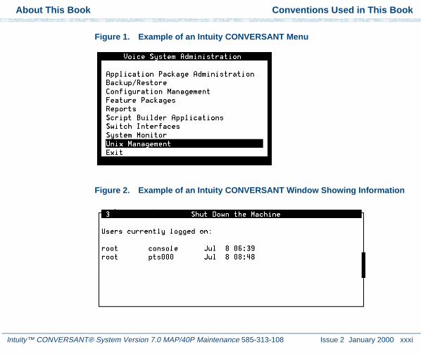
• The system displays menus, screens, and windows. Menus allow you to select options or to choose to view another menu, screen, or window (Figure 1 on page xxxi). Screens and windows both show and request system information (Figure 2 on page xxxi through Figure 5 on page xxxiii).
Note: Screens shown in this book are examples only. The screens you see on your machine will be similar, but not exactly the same.
About This Book Conventions Used in This Book
Intuity™ CONVERSANT® System Version 7.0 MAP/40P Maintenance 585-313-108 Issue 2 January 2000 xxxi
Figure 1. Example of an Intuity CONVERSANT Menu
Figure 2. Example of an Intuity CONVERSANT Window Showing Information

About This Book Conventions Used in This Book
Intuity™ CONVERSANT® System Version 7.0 MAP/40P Maintenance 585-313-108 Issue 2 January 2000 xxxii
Figure 3. Example of an Intuity CONVERSANT Screen Showing Information
Figure 4. Example of an CONVERSANT Window Requesting Information
In order to install UnixWare, you must reserve a partition (a portion of your hard disk’s space) on your primary hard disk for the UNIX System. After you press ‘ENTER’ you will be shown a screen that will allow you to create new partitions, delete existing partitions or change the active partition of your primary hard disk (the partition that your computer will boot from).
WARNING: All files in any partition(s) you delete will be destroyed. If you wish to attempt to preserve any files from an existing UNIX System, do not delete its partition(s).
The UNIX System partition that you intend to use on the primary hard disk must be at least 120 MBs and labeled ‘ACTIVE.’

About This Book Conventions Used in This Book
Intuity™ CONVERSANT® System Version 7.0 MAP/40P Maintenance 585-313-108 Issue 2 January 2000 xxxiii
Figure 5. Example of a CONVERSANT Screen Requesting Information
Keyboard and Telephone Keypad Representations
• Keys that you press on your terminal or PC are represented as small capitalized BOLD text. For example, an instruction to press the enter key is shown as:
Press ENTER.
You may use a partition of your secondary hard disk. If you choose to use a partition of your secondary hard disk you will be shown a screen that will allow you to partition your secondary hard disk.
WARNING: All files in any partition(s) you delete will be destroyed.If you choose to create a UNIX System partition on your secondary hard disk, it must be at least 40 MBs.Your Options are:
1. Do not use a partition of the secondary hard disk for the UNIX System.
2. Use a partition of the secondary hard disk for the UNIX System.
Press ‘1’ or ‘2’ followed by ‘ENTER’.
About This Book Conventions Used in This Book
Intuity™ CONVERSANT® System Version 7.0 MAP/40P Maintenance 585-313-108 Issue 2 January 2000 xxxiv
• Two or three keys that you press at the same time on your terminal or PC (that is, you hold down the first key while pressing the second and/or third key) are represented in small capitalized BOLD text. For example, an instruction to press and hold the Alt key while typing the letter “d” is shown as:
Press ALT + D.
• Function keys on your terminal, PC, or system screens, also known as soft keys, are represented as small capitalized BOLD text followed by the function or value of that key enclosed in parentheses. For example, an instruction to press function key 3 is shown as:
Press F3 (Choices).
• Keys that you press on your telephone keypad appear in small capitalized BOLD text. For example, an instruction to press the first key on your telephone keypad is shown as:
Press 1 to record a message.
Cross References and Hypertext
Blue underlined type indicates a cross reference or hypertext link that takes you to another location in the document when you click on it with your mouse.

About This Book Conventions Used in This Book
Intuity™ CONVERSANT® System Version 7.0 MAP/40P Maintenance 585-313-108 Issue 2 January 2000 xxxv
Screen Displays • Values, system messages, field names, and prompts that appear on the screen, and simulated screen displays appear in typewriter-style constant-width type, as shown in the following examples:
Enter the number of ports to be dedicated to outbound traffic in the Maximum Simultaneous Ports field.
Alarm Form Update was successful.Press <Enter> to continue.
• The sequence of menu options that you must select to display a specific screen or submenu is shown as follows:
Start at the Voice System Administration menu and select:
In this example, you would access the Voice System Administration menu and select the Reports menu. From the Reports menu, you would then select the Message Log Report window.
> Message Log Report
> Reports

About This Book Safety and Security Alert Labels
Intuity™ CONVERSANT® System Version 7.0 MAP/40P Maintenance 585-313-108 Issue 2 January 2000 xxxvi
Other Typography • Commands and text you type in or enter appear in bold type, as in the following examples:
Enter change-switch-time-zone at the enter command: prompt.
Type high or low in the Speed: field.
• Command variables are shown in bold italic type when they are part of what you must type in and blue italic type when they are not, for example:
Enter ch ma machine_name, where machine_name is the name of the call delivery machine you just created.
• Command options are shown inside square brackets, for example:
Enter connect switchname [-d] [-b | -w]
Safety and Security Alert Labels
This book uses the following symbols to call your attention to potential problems that could cause personal injury, damage to equipment, loss of data, service interruptions, or breaches of toll fraud security:
! CAUTION:Indicates the presence of a hazard that if not avoided can or will cause minor personal injury or property damage, including loss of data.

About This Book Getting Help
Intuity™ CONVERSANT® System Version 7.0 MAP/40P Maintenance 585-313-108 Issue 2 January 2000 xxxvii
WARNING:!Indicates the presence of a hazard that if not avoided can cause death or severe personal injury.
! DANGER:Indicates the presence of a hazard that if not avoided will cause death or severe personal injury.
! SECURITY ALERT:Indicates the presence of a toll fraud security hazard. Toll fraud is the unauthorized use of a telecommunications system by an unauthorized party.
Getting Help
The Intuity CONVERSANT system provides online help to assist you during installation, administration, and application development tasks.
To use the online help:
• Press F1 (Help) when you are in a menu or window.

About This Book Technical Assistance
Intuity™ CONVERSANT® System Version 7.0 MAP/40P Maintenance 585-313-108 Issue 2 January 2000 xxxviii
The first time you press F1 , the system displays information about the currently active window or menu.
~ When you are in a window, the help explains the purpose of the window and describes its fields.
~ When you are in a menu, the help explains how to use menus.
If you press F1 again, the system displays a General Help screen that explains how to use the online help.
• Press F2 (Choices) when you are in a field.
The system displays valid field choices either in a pop-up window or on the status line directly above the function keys.
• Press F6 (Cancel) to exit the online help.
Technical Assistance
Web Site The following customer support web site contains resources where you can find solutions for technical problems:
http://support.lucent.com
Contact Numbers Technical assistance on the Intuity CONVERSANT product is available through the following telephone contacts:
• In the United States, call 1-800-242-2121.

About This Book Related Resources
Intuity™ CONVERSANT® System Version 7.0 MAP/40P Maintenance 585-313-108 Issue 2 January 2000 xxxix
• In Canada, call one of the following numbers, depending on your location:
~ 1-800-363-1882 for assistance in Quebec and eastern Canada
~ 1-800-387-4268 for assistance in Ontario and western Canada
• In any other country, call your local distributor or check with your project manager or systems consultant.
Related Resources
Additional documentation and training material is available for you to learn more about the Intuity CONVERSANT product.
Training To obtain training on the Intuity CONVERSANT product, contact the BCS Education and Training Center at one of the following numbers:
• Organizations within Lucent Technologies (904) 636-3261
• Lucent Technologies customers and all others (800) 255-8988
You can also view information on Intuity CONVERSANT training at the Global Learning Solutions (GLS) web site at one of the following web links:
• Organizations within Lucent Technologies
http://training.gls.lucent.com

About This Book Related Resources
Intuity™ CONVERSANT® System Version 7.0 MAP/40P Maintenance 585-313-108 Issue 2 January 2000 xl
• Lucent Technologies customers and all others
http://www.lucenttraining.com
The courses listed below are recommended. Other courses are available.
• For technicians doing repairs on Intuity CONVERSANT V7.0 systems
~ BTT509H, CONVERSANT Installation and Maintenance Voice Information System
• For technicians and administrators
~ BTC344M, Intuity CONVERSANT V7 Administration Overview (CD-ROM)
• For application developers
~ BTC128H, Introduction to Script Builder
~ BTC166H, Introduction to Voice@Work
~ BTC204H, Intermediate Voice@Work
~ BTC301H, Advanced CONVERSANT Programming
Documentation Appendix A, "Documentation Guide," in Intuity CONVERSANT System Version 7.0 System Description, 585-313-204, describes in detail all books included in Intuity CONVERSANT documentation library and referenced in this book.

About This Book Related Resources
Intuity™ CONVERSANT® System Version 7.0 MAP/40P Maintenance 585-313-108 Issue 2 January 2000 xli
Note: Always refer to the appropriate book for specific information on planning, installing, administering, or maintaining an Intuity CONVERSANT system.
Additional Suggested Documentation
It is suggested that you also obtain and use the following book for information on security and toll fraud issues:
• GBCS Products Security Handbook, 555-025-600
For Troubleshooting Information
Basic troubleshooting information is in “Troubleshooting,” in the Intuity CONVERSANT System Reference, 585-313-205.
For Diagnostic Information
Instructions for conducting diagnostics are in “Diagnostics,” in the Intuity CONVERSANT System Reference, 585-313-205.
For Common System Procedures
Instructions for conducting common system procedures are in “Common System Procedures,” in the Intuity CONVERSANT System Reference, 585-313-205.
About This Book Using the CD-ROM Documentation
Intuity™ CONVERSANT® System Version 7.0 MAP/40P Maintenance 585-313-108 Issue 2 January 2000 xlii
For Installation Information
Instructions for installing or reinstalling system elements are in Intuity CONVERSANT System Version 7.0 New System Installation, 585-313-106.
Obtaining Printed Versions of the Documentation
See Documentation Ordering Information on page viii of Copyright and Legal Notices for information on how to purchase Intuity CONVERSANT documentation in printed form. You can also print documentation locally from the CD-ROM (see Printing the Documentation on page xliv).
Using the CD-ROM Documentation
Lucent Technologies ships the documentation in electronic form. Using the Adobe Acrobat Reader application, you can read these documents on a Windows PC, on a Sun Solaris workstation, or on an HP-UX workstation. Acrobat Reader displays high-quality, print-like graphics on both UNIX and Windows platforms. It provides scrolling, zoom, and extensive search capabilities, along with online help. A copy of Acrobat Reader is included with the documents.
Note: If viewing documents online, it is recommended that you use a separate platform and not the Intuity CONVERSANT system.

About This Book Using the CD-ROM Documentation
Intuity™ CONVERSANT® System Version 7.0 MAP/40P Maintenance 585-313-108 Issue 2 January 2000 xliii
Setting the Default Magnification
You can set your default magnification by selecting File | Preferences | General. We recommend the Fit Page option.
Adjusting the Window Size
On HP and Sun workstations, you can control the size of the reader window by using the -geometry argument. For example, the command string acroread -geometry 900x900 mainmenu.pdf opens the main menu with a window size of 900 pixels square.
Hiding and Displaying Bookmarks
By default, the document appears with bookmarks displayed on the left side of the screen. The bookmarks serve as a hypertext table of contents for the chapter you are viewing. You can control the appearance of bookmarks by selecting View | Page Only or View | Bookmarks and Page.
Using the Button Bar
The button bar can take you to the book’s Index, table of contents, main menu, and glossary. It also lets you update your documents. Click the corresponding button to jump to the section you want to read.
Using Hypertext Links
Hypertext links appears in blue underlined text. These links are shortcuts to other sections or books.
Navigating with Double Arrow Keys
The double right and double left arrows ( and ) at the top of the Acrobat Reader window are the go-back and go-forward functions. The go-back button takes you to the last page you visited prior to the current page. Typically, you use to return to the main text from a cross reference or illustration.

About This Book Using the CD-ROM Documentation
Intuity™ CONVERSANT® System Version 7.0 MAP/40P Maintenance 585-313-108 Issue 2 January 2000 xliv
Searching for Topics
Acrobat has a sophisticated search capability. From the main menu, select Tools | Search. Then select Master Index.
Displaying Figures If lines in figures appear broken or absent, increase the magnification. You might also want to print a paper copy of the figure for better resolution.
Printing the Documentation
Note: For information on purchasing printed copies of the documents, see Obtaining Printed Versions of the Documentation on page xlii.
If you would like to read the documentation in paper form rather than on a computer monitor, you can print all or portions of the online screens.
Printing an Entire Document
To print an entire document, do the following:
1 From the documentation main menu screen, select one of the print-optimized documents. Print-optimized documents print two-screens to a side, both sides of the sheet on 8.5x11-inch or A4 paper.
2 Select File | Print.
3 Enter the page range you want to print, or select All. Note that the print page range is different from the page numbers on the documents (they print two to a page).
4 The document prints.

About This Book How To Comment on This Book
Intuity™ CONVERSANT® System Version 7.0 MAP/40P Maintenance 585-313-108 Issue 2 January 2000 xlv
5 Close the file. Do not leave this file open while viewing the electronic documents.
Printing Part of a Document
To print a single page or a short section, you can print directly from the online version of the document.
1 Select File | Print.
2 Enter the page range you want to print, or select Current.
The document prints, one screen per side, two sides per sheet.
How To Comment on This Book
While we have tried to make this document fit your needs, we are interested in your suggestions for improvement and urge you to send comments to us.
About This Book How To Comment on This Book
Intuity™ CONVERSANT® System Version 7.0 MAP/40P Maintenance 585-313-108 Issue 2 January 2000 xlvi
Comment Form A comment form, in paper and electronic versions, is available via the documentation CD-ROM. To use the comment form:
1 Select Comments from the Main Menu of the CD-ROM.
2 Follow the instructions provided on the CD-ROM to either:
~ Print the paper version of the form, complete it, and fax or mail it to us.
~ Access a Lucent Technologies website where you can enter your comments electronically.

About This Book How To Comment on This Book
Intuity™ CONVERSANT® System Version 7.0 MAP/40P Maintenance 585-313-108 Issue 2 January 2000 xlvii
Contact Us Directly If you prefer not to use the comment form, you can contact us directly at the following address or fax number.
Lucent TechnologiesGLS Information Development DivisionRoom 22-2H1511900 North Pecos StreetDenver, CO 80234-2703 US
Fax 1 303-538-1741
Note: Direct your correspondence to the attention of the Lucent Technologies Intuity CONVERSANT writing team. Be sure to mention the title of the book on which you are commenting.

Intuity™ CONVERSANT® System Version 7.0 MAP/40P Maintenance 585-313-108 Issue 2 January 2000 1
1 Getting Inside the Computer
Overview
This chapter provides the correct procedures for accessing the internal components of the MAP/40P.
Topics covered include:
• Protecting Against Damage from Electrostatic Discharge on page 2
• Power removal and restoration procedures
~ Removing Power from the MAP/40P on page 6
~ Restoring Power to the MAP/40P on page 10
• Computer chassis access procedures
~ Removing the Dress Cover on page 9
~ Replacing the Dress Cover on page 10

1 Getting Inside the Computer Protecting Against Damage from Electrostatic Discharge
Intuity™ CONVERSANT® System Version 7.0 MAP/40P Maintenance 585-313-108 Issue 2 January 2000 2
Protecting Against Damage from Electrostatic Discharge
! CAUTION:Read this section before unpacking the MAP/40P. You must observe proper grounding techniques to prevent the discharge of static electricity from your body into ESD-sensitive components.
Circuit cards and packaging materials that contain ESD-sensitive components are usually marked with a yellow-and-black warning symbol (Figure 6 on page 2).
Figure 6. ESD Warning Symbol
ATTENTIONOBSERVE PRECAUTIONS
FOR HANDLING
ELECTROSTATICSENSITIVEDEVICES

1 Getting Inside the Computer Protecting Against Damage from Electrostatic Discharge
Intuity™ CONVERSANT® System Version 7.0 MAP/40P Maintenance 585-313-108 Issue 2 January 2000 3
To avoid damaging ESD-sensitive components, follow these rules:
• Handle ESD-sensitive circuit cards only after attaching a wrist strap to the bare wrist. Attach the other end of the wrist strap to a ground that terminates at the system ground, such as any unpainted metallic chassis surface.
• Handle a circuit card by the faceplate or side edges only (Figure 7 on page 4 and Figure 8 on page 5).
! CAUTION:Ensure that your palm is not in contact with the non-component side of the board.
• Keep circuit cards away from plastics and other synthetic materials such as polyester clothing.
• Do not hand circuit cards to another person unless that person is grounded at the same potential level.
• Hold devices such as a hard disk, floppy drive, or streaming tape in the same manner as a large circuit card. The ESD-sensitive area of these components is located on the bottom surface (Figure 9 on page 6).

1 Getting Inside the Computer Protecting Against Damage from Electrostatic Discharge
Intuity™ CONVERSANT® System Version 7.0 MAP/40P Maintenance 585-313-108 Issue 2 January 2000 4
Figure 7. How to Hold a Small Circuit Card

1 Getting Inside the Computer Protecting Against Damage from Electrostatic Discharge
Intuity™ CONVERSANT® System Version 7.0 MAP/40P Maintenance 585-313-108 Issue 2 January 2000 5
Figure 8. How to Hold a Large Circuit Card

1 Getting Inside the Computer Removing Power from the MAP/40P
Intuity™ CONVERSANT® System Version 7.0 MAP/40P Maintenance 585-313-108 Issue 2 January 2000 6
Figure 9. ESD-Sensitive Area of an Electronic Component
Removing Power from the MAP/40P
The MAP/40P requires a dedicated circuit with a dedicated circuit breaker. The power cord connects to the rear of the MAP/40P at the point labeled AC input receptacle (Figure 10 on page 7).
Before you begin any work in the MAP/40P you must disconnect the incoming power. Follow the procedure below to remove power from the MAP/40P.
Recommendedholding points
ESD sensitivearea (bottomsurface)

1 Getting Inside the Computer Removing Power from the MAP/40P
Intuity™ CONVERSANT® System Version 7.0 MAP/40P Maintenance 585-313-108 Issue 2 January 2000 7
Figure 10. Back View of the MAP/40P
h2mxrear KLC 081997
1
2
3
4
6
7
8
9
10
5
1.AC power inlet receptacle
2.AC power supply outlet
3.External SCSI I/O connector
4.Parallel port
5.COM2
6.Keyboard connector
7.Power supply fan exhaust
8.Mouse connector - (not used)
9.Video connector
10.COM1

1 Getting Inside the Computer Removing Power from the MAP/40P
Intuity™ CONVERSANT® System Version 7.0 MAP/40P Maintenance 585-313-108 Issue 2 January 2000 8
1 Shut down the voice system. See “Administer the Voice System,” in “Common System Procedures,” in the Intuity CONVERSANT System Reference, 585-313-205.”
2 Shut down the Intuity CONVERSANT system. See “Shut Down the System,” in “Common System Procedures,” in the Intuity CONVERSANT System Reference, 585-313-205.
3 Turn off the monitor’s power switch.
The green or amber lamp on the front bottom of the monitor should be off.
4 Turn off the power switch on the front of the MAP/40P.
The green lamp, labeled POWER ON, on the front of the unit should be off.
5 Unplug the MAP/40P from the power outlet.
6 Remove the MAP/40P power cord from the AC input receptacle on the rear of the MAP/40P (Figure 10 on page 7).
7 Observe the correct lock-out/tag-out precautions for isolating power as outlined in the Lucent lock-out/tag-out procedure.

1 Getting Inside the Computer Removing the Dress Cover
Intuity™ CONVERSANT® System Version 7.0 MAP/40P Maintenance 585-313-108 Issue 2 January 2000 9
Removing the Dress Cover
The dress cover provides protection for the internal components of the MAP/40P. You must remove the dress cover to access these components.
WARNING:!Shut power off before removing the dress cover or access panel of the MAP/40P. See Removing Power from the MAP/40P on page 6.
1 Ensure that the MAP/40P tower configuration is in an upright position on the support base.
2 Remove the six screws located along the bottom of the MAP/40P, one located midway up the left side toward the front, and one in the middle of the rear of the chassis.
Note: You will need a No. 2 Phillips screwdriver.
There are three screws on each side of the MAP/40P.
3 Remove the screw holding the dress cover to the rear of the MAP/40P.
4 Remove the front bezel by pulling it forward.
5 At the rear of the MAP/40P, pry both sides of the dress cover away from the unit.
6 Slide the dress cover up to remove it from the MAP/40P.
1 Getting Inside the Computer Replacing the Dress Cover
Intuity™ CONVERSANT® System Version 7.0 MAP/40P Maintenance 585-313-108 Issue 2 January 2000 10
Replacing the Dress Cover
1 Place the MAP/40P in the upright position.
2 Slide the dress cover over the unit.
3 Replace and tighten the eight dress cover retaining screws.
Restoring Power to the MAP/40P
The MAP/40P requires a dedicated power line. The power cord connects to the rear of the MAP/40P at the point labeled Input Receptacle (Figure 10 on page 7).
Follow the procedure below to restore power to the MAP/40P.
1 Place the MAP/40P power cord in the AC input receptacle on the rear of the unit (Figure 10 on page 7).
2 Plug the MAP/40P power cord into the designated power outlet.
3 Turn on the power switch on the front of the MAP/40P.
The green lamp, labeled POWER ON, on the front of the unit should be lit.
4 Turn on the monitor’s power switch.
The green or amber lamp on the front bottom of the monitor should be lit.

Intuity™ CONVERSANT® System Version 7.0 MAP/40P Maintenance 585-313-108 Issue 2 January 2000 11
2 Installing or Replacing CircuitCards
Overview
The purpose of this chapter is to ensure that:
• Circuit cards are installed correctly
• Resource options are set correctly
Topics covered include:
• Configuring circuit cards in the MAP/40P
• Types of circuit cards
• General steps for circuit card installation
• Specific procedures for installation of standard and optional MAP/40P circuit cards
• Settings for resource options

2 Installing or Replacing Circuit Cards General Procedures
Intuity™ CONVERSANT® System Version 7.0 MAP/40P Maintenance 585-313-108 Issue 2 January 2000 12
General Procedures
The general procedures include:
• Removing a Circuit Card on page 12
• Installing a Circuit Card on page 14
Removing a Circuit Card
! CAUTION:Observe proper electrostatic discharge precautions when you handle computer components. Wear an antistatic wrist strap that touches your bare skin and connect the strap cable to an earth ground. See Protecting Against Damage from Electrostatic Discharge on page 2, in Chapter 1, Getting Inside the Computer for detailed electrostatic discharge precautions.
To remove a circuit card, do the following.
1 Verify that the replacement equipment is on site and appears to be in usable condition, with no obvious shipping damage.
Note: If the circuit card being replaced is defective, note all symptoms of failure and include this information with the circuit card when it is returned.

2 Installing or Replacing Circuit Cards General Procedures
Intuity™ CONVERSANT® System Version 7.0 MAP/40P Maintenance 585-313-108 Issue 2 January 2000 13
2 If the system is in service, do the following:
a Stop the voice system. See “Administer the Voice System,” in “Common System Procedures,” in the Intuity CONVERSANT System Reference, 585-313-205.
b Shut down the voice system. See “Administer the Voice System,” in “Common System Procedures,” in the Intuity CONVERSANT System Reference, 585-313-205.
c Shut down the Intuity CONVERSANT system. See “Shut Down the System,” in “Common System Procedures,” in the Intuity CONVERSANT System Reference, 585-313-205.
3 Remove power from the MAP/40P. See Removing Power from the MAP/40P on page 6 in Chapter 1, Getting Inside the Computer .
4 Remove the dress cover. See Removing the Dress Cover on page 9 in Chapter 1, Getting Inside the Computer .
5 Locate the card to be replaced within the card cage. Disconnect any attached cables. Note the connectivity of each cable.
6 If there are ribbon cables attached to other cards which would impede the removal of the card, disconnect them and place them to the side. Note the connectivity of each cable.
7 Remove the retaining screw from the circuit card faceplate and save it.

2 Installing or Replacing Circuit Cards General Procedures
Intuity™ CONVERSANT® System Version 7.0 MAP/40P Maintenance 585-313-108 Issue 2 January 2000 14
8 Remove the circuit card from the backplane slot by gently pulling at the top corners of the circuit card.
Note: The backplane connector slots are labeled 1 through 20. Make sure to install the replacement card in the same backplane slot.
9 Remove the circuit card from the MAP/40P chassis.
! CAUTION:Hold the circuit card carefully by the edges and place it on a grounded mat. See Protecting Against Damage from Electrostatic Discharge on page 2 in Chapter 1, “Getting Inside the Computer,” for detailed electrostatic discharge precautions.
Installing a Circuit Card
! CAUTION:Observe proper electrostatic discharge precautions when you handle computer components. Wear an antistatic wrist strap that touches your bare skin and connect the strap cable to an earth ground. See Protecting Against Damage from Electrostatic Discharge on page 2 in Chapter 1, Getting Inside the Computer for detailed electrostatic discharge precautions.
To install a circuit card, do the following:
1 Remove the new circuit card from its ESD protective wrapping.

2 Installing or Replacing Circuit Cards General Procedures
Intuity™ CONVERSANT® System Version 7.0 MAP/40P Maintenance 585-313-108 Issue 2 January 2000 15
Note: Keep the package and all ESD protective wrapping. If you must return a card for repair, re-use of the replacement unit packaging is necessary to meet the manufacturer’s warranty.
2 Verify the circuit card switch and jumper settings. Ensure address switches and jumpers are set to match the old card.
Note: See the specific instructions, listed later in this chapter, for each type of circuit card being installed then continue with step 3.
3 Holding the circuit card by its upper corners, slide the card into the backplane connector slot position from which you removed the damaged card.
4 Apply even pressure to both corners of the circuit card until it is locked into the backplane.
5 Secure the circuit card faceplate into position by replacing the retaining screw.
6 Return all cables on the new card. Make sure these cables are attached to their proper terminations.
7 Return all cables removed from other cards. Make sure these cables are attached to their proper terminations.
8 Replace the side dress cover. See Replacing the Dress Cover on page 10 in Chapter 1, Getting Inside the Computer .

2 Installing or Replacing Circuit Cards Settings for Optional Circuit Cards
Intuity™ CONVERSANT® System Version 7.0 MAP/40P Maintenance 585-313-108 Issue 2 January 2000 16
9 Apply power to the unit. See Restoring Power to the MAP/40P on page 10, in Chapter 1, Getting Inside the Computer .
10 Reboot the Intuity CONVERSANT system. See “Reboot the System,” in “Common System Procedures,” in the Intuity CONVERSANT System Reference, 585-313-205.
Settings for Optional Circuit Cards
! CAUTION:Observe proper electrostatic discharge precautions when you handle computer components. Wear an antistatic wrist strap that touches your bare skin and connect the strap cable to an earth ground. See Protecting Against Damage from Electrostatic Discharge on page 2, in Chapter 1, Getting Inside the Computer for detailed electrostatic discharge precautions.
This section provides the following information on the optional feature circuit cards:
• Switch and jumper settings
• Other installation requirements that are specific to the particular circuit card you are installing

2 Installing or Replacing Circuit Cards Settings for Optional Circuit Cards
Intuity™ CONVERSANT® System Version 7.0 MAP/40P Maintenance 585-313-108 Issue 2 January 2000 17
In general, circuit cards are not preset at the factory. You must set the switches and jumpers (resource options) BEFORE you install the cards. When you set the switches according to the instructions in this book, remember that OFF is equivalent to open and ON is equivalent to closed.
Tip/Ring Circuit Cards
The Tip/Ring circuit cards provide the channels which are used by the Intuity CONVERSANT system. The MAP/40P accommodates eleven Tip/Ring circuit cards. The Tip/Ring circuit card can be any of the following types:
• AYC29 (IVP6-IA)
• AYC10 (IVC6)
• AYC30 (NGTR)
The following section covers the resource option settings for each type of T/R card. Many of the figures referenced illustrate settings for more than one type of T/R card.
The six switches on Switch Bank A adjust the termination impedance that each Tip/Ring interface presents to the network. This adjustment is sometimes necessary to ensure an adequate impedance match between the network and the telephone hybrid on the Tip/Ring card.
Switches one (1) through six (6) on Switch Bank A correspond to channels 0-5, respectively, on each Tip/Ring card.

2 Installing or Replacing Circuit Cards Settings for Optional Circuit Cards
Intuity™ CONVERSANT® System Version 7.0 MAP/40P Maintenance 585-313-108 Issue 2 January 2000 18
In general, you should leave all switches on Switch Bank A in the factory default “OPEN” position. If the system shows problems such as not recognizing touch tones, touch-tone simulation by outgoing speech (speech abruptly stops during playback), or unreliable detection of touch tones during playback (playback does not stop when a touch tone is entered), moving the switch that corresponds to the channel exhibiting the conditions to the “CLOSED” position may solve the problem.
Each Tip/Ring card in the system must have a unique address. To set these addresses, set Switch Bank B as shown in Figure 11 on page 19, where “T/R 0” denotes the first Tip/Ring circuit card you are installing, “T/R 1” denotes the second card, and so on.

2 Installing or Replacing Circuit Cards Settings for Optional Circuit Cards
Intuity™ CONVERSANT® System Version 7.0 MAP/40P Maintenance 585-313-108 Issue 2 January 2000 19
Figure 11. Settings for Switches on the IVP6-IA (AYC29), and IVC6 (AYC10) Tip/Ring Circuit Cards T/R-0 through T/R-7
Rocker switches 5and 6 can be seteither open or closed.
Note:
Base I/O address = 100 Hex.
IVC6-IU T/R 0First card installed
Base I/O address = 200 Hex.
IVC6-IU T/R 1Second card installed
Base I/O address = 300 Hex.
IVC6-IU T/R 2Third card installed
Base I/O address = 500 Hex.
IVC6-IU T/R 3Fourth card installed
Base I/O address = 600 Hex.
IVC6-IU T/R 4Fifth card installed
Base I/O address = 700 Hex.
Base I/O address = b00 Hex.
IVC6-IU T/R 5Sixth card installed
IVC6-IU T/R 8Ninth card installed
Base I/O address = 900 Hex.
Base I/O address = d00 Hex.
IVC6-IU T/R 6Seventh card installed
IVC6-IU T/R 9Tenth card installed
Base I/O address = a00 Hex.
Base I/O address = e00 Hex.
IVC6-IU T/R 7Eighth card installed
IVC6-IU T/R 10Eleventh card installed

2 Installing or Replacing Circuit Cards Settings for Optional Circuit Cards
Intuity™ CONVERSANT® System Version 7.0 MAP/40P Maintenance 585-313-108 Issue 2 January 2000 20
IVP6-IA (AYC29) Circuit Card
The IVP6-IA (AYC29) circuit card (Figure 12 on page 21) provides six channels.
Note: This circuit card contains switches that you must set before you install the circuit card in the MAP/40P.
Each Tip/Ring card in the system must have a unique address. To set these addresses, the switches must be configured properly. Figure 11 on page 19 shows the switch settings for the IVP6-IA (AYC29) circuit card.
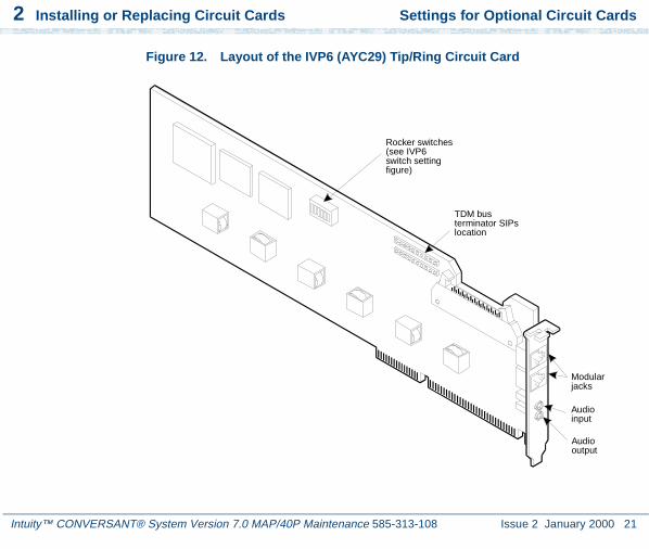
2 Installing or Replacing Circuit Cards Settings for Optional Circuit Cards
Intuity™ CONVERSANT® System Version 7.0 MAP/40P Maintenance 585-313-108 Issue 2 January 2000 21
Figure 12. Layout of the IVP6 (AYC29) Tip/Ring Circuit Card
Modularjacks
Audioinput
Audiooutput
TDM busterminator SIPslocation
Rocker switches(see IVP6switch settingfigure)

2 Installing or Replacing Circuit Cards Settings for Optional Circuit Cards
Intuity™ CONVERSANT® System Version 7.0 MAP/40P Maintenance 585-313-108 Issue 2 January 2000 22
IVC6 (AYC10) Circuit Card
The IVC6 (AYC10) circuit card (Figure 13 on page 23) provides six channels.
Note: This circuit card contains switches that you must set before you install the circuit card in the MAP/40P.
Each Tip/Ring card in the system must have a unique address. To set these addresses, the switches must be configured properly. Figure 11 on page 19 shows the switch settings for the IVC6 (AYC10) circuit card.

2 Installing or Replacing Circuit Cards Settings for Optional Circuit Cards
Intuity™ CONVERSANT® System Version 7.0 MAP/40P Maintenance 585-313-108 Issue 2 January 2000 23
Figure 13. (AYC10) Tip/Ring Circuit Card
8-pinmodularjacks
Audioinput
Audiooutput
TDM busterminator SIPs
Rockerswitches(see IVC6switch settingfigure)

2 Installing or Replacing Circuit Cards Settings for Optional Circuit Cards
Intuity™ CONVERSANT® System Version 7.0 MAP/40P Maintenance 585-313-108 Issue 2 January 2000 24
NGTR (AYC30) Circuit Card
The NGTR (AYC30) circuit card (Figure 14 on page 25) provides six channels.
Note: This circuit card contains switches that you must set before you install the circuit card in the MAP/40P.
Each Tip/Ring circuit card in the system must have a unique address. To set these addresses, the switch must be configured properly. Figure 15 on page 26 shows the switch settings for the NGTR (AYC30) circuit card.

2 Installing or Replacing Circuit Cards Settings for Optional Circuit Cards
Intuity™ CONVERSANT® System Version 7.0 MAP/40P Maintenance 585-313-108 Issue 2 January 2000 25
Figure 14. NGTR (AYC30)
KLC 070296
I/O address switch
TDM bus B
TDM bus A
TDM bus terminator SIPs
8-pinmodularjacks
Audiooutput
Audioinput

2 Installing or Replacing Circuit Cards Settings for Optional Circuit Cards
Intuity™ CONVERSANT® System Version 7.0 MAP/40P Maintenance 585-313-108 Issue 2 January 2000 26
Figure 15. NGTR (AYC30) Tip/Ring Circuit Card Switch Settings

2 Installing or Replacing Circuit Cards Settings for Optional Circuit Cards
Intuity™ CONVERSANT® System Version 7.0 MAP/40P Maintenance 585-313-108 Issue 2 January 2000 27
Installing the Tip/Ring Circuit Card Driver
Note: If the Tip/Ring circuit cards are not recognized when the voice system is started or if other problems are noticed with the Tip/Ring circuit card driver, it may be necessary to remove and reinstall the Tip/Ring circuit card driver.
Occasionally dynamically loadable drivers fail to load into the UnixWare kernel properly.
To install the Tip/Ring circuit card driver, do the following:
1 Stop the voice system. See “Administer the Voice System,” in “Common System Procedures,” in the Intuity CONVERSANT System Reference, 585-313-205.
2 Run the Hardware Resource Allocator to determine the configuration and placement of the Tip/Ring circuit cards to be installed. See Adding Hardware to an Existing Configuration on page 468 in Appendix A, System Configuration.
3 If you are not already logged in as root, do so now.
4 Enter pkgadd -d diskette1
The system displays the following message:
Insert diskette into Floppy Drive 1.Type [go] when ready,
or [q] to quit: (default: go)
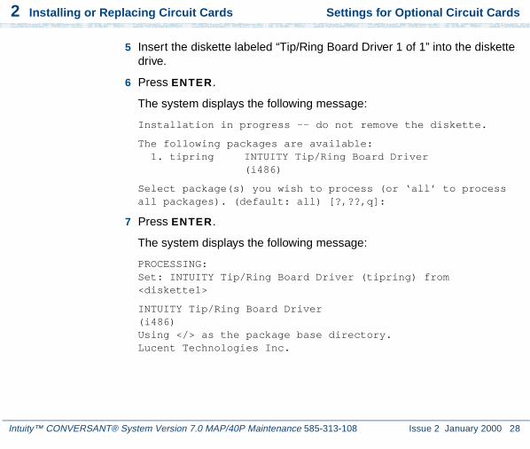
2 Installing or Replacing Circuit Cards Settings for Optional Circuit Cards
Intuity™ CONVERSANT® System Version 7.0 MAP/40P Maintenance 585-313-108 Issue 2 January 2000 28
5 Insert the diskette labeled “Tip/Ring Board Driver 1 of 1” into the diskette drive.
6 Press ENTER.
The system displays the following message:
Installation in progress -- do not remove the diskette.
The following packages are available: 1. tipring INTUITY Tip/Ring Board Driver
(i486)
Select package(s) you wish to process (or ‘all’ to process all packages). (default: all) [?,??,q]:
7 Press ENTER.
The system displays the following message:
PROCESSING:Set: INTUITY Tip/Ring Board Driver (tipring) from <diskette1>
INTUITY Tip/Ring Board Driver(i486)Using </> as the package base directory.Lucent Technologies Inc.

2 Installing or Replacing Circuit Cards Settings for Optional Circuit Cards
Intuity™ CONVERSANT® System Version 7.0 MAP/40P Maintenance 585-313-108 Issue 2 January 2000 29
The system displays several status messages and then the following message:
Please enter the IRQ:
8 Enter the IRQ provided by the Hardware Resource Allocator.
The system displays several status messages and then the following message:
Installation of INTUITY Tip/Ring Board Driver (tipring) was successful.
Insert diskette into Floppy Drive 1.Type [go] when ready,
or [q] to quit: (default: go)
9 Enter q
10 Remove the diskette labeled “Tip/Ring Board Driver 1 of 1” from the diskette drive.
E1/T1 Circuit Card
Note: The E1/T1 circuit card (Figure 16 on page 30) contains switches and jumpers that you must set before you install the circuit card in the MAP/40P.

2 Installing or Replacing Circuit Cards Settings for Optional Circuit Cards
Intuity™ CONVERSANT® System Version 7.0 MAP/40P Maintenance 585-313-108 Issue 2 January 2000 30
Figure 16. E1/T1 (AYC21) Circuit Card
TDM bus B(reserved forfuture use)
TDM bus A
Bus Bterminating
resistors
Bus Aterminating
resistors
LED
8-pinmodular
jack
TXconnector
(signal out)
RXconnector(signal in)
SW1(device number)
SW2(operating mode)
Test port(lab use only)
J8(shield ground)
J7(IRQ select)

2 Installing or Replacing Circuit Cards Settings for Optional Circuit Cards
Intuity™ CONVERSANT® System Version 7.0 MAP/40P Maintenance 585-313-108 Issue 2 January 2000 31
Jumper Settings Figure 17 on page 31 shows the location and correct setting of the E1/T1 circuit card jumpers.
Figure 17. AYC21 Jumper Settings
Switch Settings There are two sets of switches on the E1/T1 circuit card. Figure 18 on page 32, Figure 19 on page 33, and Figure 20 on page 33 show the correct switch settings.
68302
J12 (IRQ select)
J8
Ground RX outer conductor
Ground TX outer conductor
7

2 Installing or Replacing Circuit Cards Settings for Optional Circuit Cards
Intuity™ CONVERSANT® System Version 7.0 MAP/40P Maintenance 585-313-108 Issue 2 January 2000 32
Figure 18. AYC21 Device Number Switch 1 Settings

2 Installing or Replacing Circuit Cards Settings for Optional Circuit Cards
Intuity™ CONVERSANT® System Version 7.0 MAP/40P Maintenance 585-313-108 Issue 2 January 2000 33
Figure 19. AYC21 Operating Mode Switch Settings for E1 Operation
Figure 20. AYC21 Operating Mode Switch Settings for T1 Operation
CEPT/E175 ohm, BNC jack
CEPT/E1120 ohm, modular jack

2 Installing or Replacing Circuit Cards Settings for Optional Circuit Cards
Intuity™ CONVERSANT® System Version 7.0 MAP/40P Maintenance 585-313-108 Issue 2 January 2000 34
Installing the E1/T1 Circuit Card Driver
Note: If the E1/T1 circuit cards are not recognized when the voice system is started or if other problems are noticed with the E1/T1 circuit card driver, it may be necessary to remove and reinstall the E1/T1 circuit card driver.
Occasionally dynamically loadable drivers fail to load into the UnixWare kernel properly.
To install the E1/T1 circuit card driver, do the following:
1 If you are not already logged in as root, do so now.
2 Stop the voice system. See “Administer the Voice System,” in “Common System Procedures,” in the Intuity CONVERSANT System Reference, 585-313-205.
3 Enter pkgadd -d diskette1
The system displays the following message:
Insert diskette into Floppy Drive 1.Type [go] when ready,
or [q] to quit: (default: go)
4 Insert the diskette labeled “T1/E1 Board Driver 1 of 3” into the diskette drive.
5 Press ENTER.

2 Installing or Replacing Circuit Cards Settings for Optional Circuit Cards
Intuity™ CONVERSANT® System Version 7.0 MAP/40P Maintenance 585-313-108 Issue 2 January 2000 35
The system displays the following message:
Installation in progress -- do not remove the diskette.
The following packages are available: 1. t1driver INTUITY T1/E1 Board Driver
(i486)
Select package(s) you wish to process (or ‘all’ to process all packages). (default: all) [?,??,q]:
6 Press ENTER.
The system displays the following message:
PROCESSING:Set: INTUITY T1/E1 Board Driver (t1driver) from <diskette1>
INTUITY T1/E1 Board Driver(i486)Using </> as the package base directory.Lucent Technologies Inc.
The system displays several status messages and then the following message:
READY TO PROCESS:Package: INTUITY T1/E1 Board Driver (t1driver)
diskette 2 of 3

2 Installing or Replacing Circuit Cards Settings for Optional Circuit Cards
Intuity™ CONVERSANT® System Version 7.0 MAP/40P Maintenance 585-313-108 Issue 2 January 2000 36
Insert diskette 2 of 3 into Floppy Drive 1.Type [go] when ready,
or [q] to quit: (default: go)
7 Remove the diskette labeled “T1/E1 Board Driver 1 of 3” from the diskette drive.
8 Insert the diskette labeled “T1/E1 Board Driver 2 of 3” into the diskette drive.
9 Press ENTER.
The system displays several status messages and then the following message:
READY TO PROCESS:Package: INTUITY T1/E1 Board Driver (t1driver)
diskette 3 of 3
Insert diskette 3 of 3 into Floppy Drive 1.Type [go] when ready,
or [q] to quit: (default: go)
10 Remove the diskette labeled “T1/E1 Board Driver 2 of 3” from the diskette drive.
11 Insert the diskette labeled “T1/E1 Board Driver 3 of 3” into the diskette drive.
12 Press ENTER.

2 Installing or Replacing Circuit Cards Settings for Optional Circuit Cards
Intuity™ CONVERSANT® System Version 7.0 MAP/40P Maintenance 585-313-108 Issue 2 January 2000 37
The system displays several status messages and then the following message:
Installation of T1/E1 Board Driver (t1driver) was successful.
Insert diskette into Floppy Drive 1.Type [go] when ready,
or [q] to quit: (default: go)
13 Enter q
14 Remove the diskette labeled “T1/E1 Board Driver 3 of 3” from the diskette drive.
Speech and Signal Processor (AYC43) Circuit Card
Note: The SSP circuit card (Figure 21 on page 38) contains switches that you must set before you install the circuit card in the MAP/40P.

2 Installing or Replacing Circuit Cards Settings for Optional Circuit Cards
Intuity™ CONVERSANT® System Version 7.0 MAP/40P Maintenance 585-313-108 Issue 2 January 2000 38
Figure 21. Speech and Signal Processor Circuit Card
Jumper Settings Figure 21 on page 38 shows a location for jumpers. However, there should be no jumpers installed on the SSP circuit card.

2 Installing or Replacing Circuit Cards Settings for Optional Circuit Cards
Intuity™ CONVERSANT® System Version 7.0 MAP/40P Maintenance 585-313-108 Issue 2 January 2000 39
Switch Settings There are two types of switches on the SSP circuit card:
• Two-position switches
• Rotary switch
Two-Position Switch Settings
Figure 22 on page 39 shows the location of the SSP circuit card two-position switches. If the SSP circuit card is not located at the end of the TDM bus, both switches should be set to open. The switches should be set to closed if the SSP circuit card is located at the end of the bus.
Figure 22. SSP Circuit Card Two-Position Switches (Set for a Placement in the Middle of the TDM Bus)
Rotary Switch Settings
Figure 23 on page 40 shows the rotary switch. It is set at zero for the first SSP circuit card installed in the MAP/40P.

2 Installing or Replacing Circuit Cards Settings for Optional Circuit Cards
Intuity™ CONVERSANT® System Version 7.0 MAP/40P Maintenance 585-313-108 Issue 2 January 2000 40
Figure 23. SSP Circuit Card Rotary Switch
Table 1 on page 40 shows the rotary switch settings for the subsequent SSP circuit cards installed.
Table 1. SSP Circuit Card Rotary Switch Setting
I/O Address OS Index Rotary Switch Setting
d20 8 0
d28 9 1
d30 10 2
d38 11 3
920 12 4
928 13 51 of 2

2 Installing or Replacing Circuit Cards Settings for Optional Circuit Cards
Intuity™ CONVERSANT® System Version 7.0 MAP/40P Maintenance 585-313-108 Issue 2 January 2000 41
Memory The SSP circuit card is equipped with 16 Mbytes of memory contained on a dual in-line memory module (DIMM). The DIMM is located in the lower portion of the SSP circuit card (Figure 21 on page 38).
! CAUTION:The DIMM is not field serviceable.
Installing the ASP Driver Package
To install the ASP circuit card driver, do the following:
1 Stop the voice system. See “Administer the Voice System,” in “Common System Procedures,” in Intuity CONVERSANT System Reference, 585-313-205.
2 At the UNIX prompt, enter pkgadd -d diskette1
930 14 6
938 15 7
Table 1. SSP Circuit Card Rotary Switch Setting
I/O Address OS Index Rotary Switch Setting
2 of 2

2 Installing or Replacing Circuit Cards Settings for Optional Circuit Cards
Intuity™ CONVERSANT® System Version 7.0 MAP/40P Maintenance 585-313-108 Issue 2 January 2000 42
The system displays the following message:
Insert diskette into Floppy Drive 1.Type [go] when ready,
or [q] to quit: (default: go)
3 Insert the diskette labeled “ASP Driver Package 1 of 2” into the diskette drive.
4 Press ENTER.
The system displays the following message:
Installation in progress -- do not remove the diskette.
The following packages are available: 1. asp INTUITY ASP Driver Package
(i486) cs3.1
Select package(s) you wish to process (or ‘all’ to process all packages). (default: all) [?,??,q]:
5 Press ENTER.
The system displays the following message:
PROCESSING:Set: INTUITY ASP Driver Package (asp) from <diskette1>
INTUITY ASP Driver Package(i486) cs3.1Using </> as the package base directory.

2 Installing or Replacing Circuit Cards Settings for Optional Circuit Cards
Intuity™ CONVERSANT® System Version 7.0 MAP/40P Maintenance 585-313-108 Issue 2 January 2000 43
Note: If you did not stop the voice system, the system displays the following message at this point:
The voice system is currently running and must be
stopped in order to install this package.
Is it ok to STOP the voice system ? [y/n]
Enter y
The system displays the following message:
READY TO PROCESS:
Package: INTUITY ASP Driver Package (asp)
diskette 2 of 2
Insert diskette 2 of 2 into Floppy Drive 1.
Type [go] when ready,
or [q] to quit: (default: go)
6 Remove the diskette labeled “ASP Driver Package 1 of 2” from the diskette drive.
7 Insert the diskette labeled “ASP Driver Package 2 of 2” into the diskette drive.
8 Press ENTER.

2 Installing or Replacing Circuit Cards Settings for Optional Circuit Cards
Intuity™ CONVERSANT® System Version 7.0 MAP/40P Maintenance 585-313-108 Issue 2 January 2000 44
The system displays several status messages and then the following message:
The UNIX Operating System kernel will be rebuilt to include your configuration changes during the next system reboot.
Installation of INTUITY ASP Driver Package (asp) was successful.
Insert diskette into Floppy Drive 1.Type [go] when ready,
or [q] to quit: (default: go)
9 Enter q
10 Make sure the light on the diskette drive is off, and remove the diskette from the drive.
Reboot the system. See “Reboot the System,” in “Common System Procedures,” in Intuity CONVERSANT System Reference, 585-313-205.
PCI Ethernet LAN Circuit Cards
The system supports two versions of the PCI Ethernet LAN circuit card
~ SMC8432
~ SMC9332

2 Installing or Replacing Circuit Cards Settings for Optional Circuit Cards
Intuity™ CONVERSANT® System Version 7.0 MAP/40P Maintenance 585-313-108 Issue 2 January 2000 45
SMC8432 Circuit Card
The SMC8432 Ethernet LAN circuit card is a 10-Mbps circuit card. Figure 24 on page 45 shows the SMC8432 Ethernet LAN circuit card.
Note: There are no jumpers on the circuit card. Figure 24. SMC8432 Ethernet LAN Circuit Card
cdcvpclb LJK 051497

2 Installing or Replacing Circuit Cards Settings for Optional Circuit Cards
Intuity™ CONVERSANT® System Version 7.0 MAP/40P Maintenance 585-313-108 Issue 2 January 2000 46
SMC9332 Circuit Card
The SMC9332 Ethernet LAN circuit card is a 10/100-Mbps circuit card. Figure 25 on page 46 shows the SMC9332 Ethernet LAN circuit card.
Note: There are no jumpers on the circuit card.Figure 25. SMC9332 Ethernet LAN Circuit Card
cdcvpcla LJK 051497

2 Installing or Replacing Circuit Cards Settings for Optional Circuit Cards
Intuity™ CONVERSANT® System Version 7.0 MAP/40P Maintenance 585-313-108 Issue 2 January 2000 47
Installing a PCI LAN Circuit Card
Installation of a 10 Mbps or a 10/100 Mbps PCI LAN circuit card, in a system which did not previously have a LAN circuit card, involves
• Installing the PCI LAN Circuit Card on page 47
• CMOS Parameter Settings on page 92
• Installing the PCI Circuit Card Driver on page 49
• Verifying the PCI LAN Circuit Card Installation on page 52
Installing the PCI LAN Circuit Card
To install either a 10 Mbps or a 10/100 Mbps PCI LAN circuit card, do the following:
1 Shut down the system if it is running; otherwise continue with step 2. See “Shut Down the System,” in “Common System Procedures,” in the Intuity CONVERSANT System Reference, 585-313-205.
2 Install the 10 Mbps or 10/100 Mbps PCI LAN circuit card. See Installing a Circuit Card on page 14.
3 Administer the PCI INT/IRQ Binding. See CMOS Parameter Settings on page 92.

2 Installing or Replacing Circuit Cards Settings for Optional Circuit Cards
Intuity™ CONVERSANT® System Version 7.0 MAP/40P Maintenance 585-313-108 Issue 2 January 2000 48
Installing a 100 Mbps PCI LAN Circuit Card
Note: Perform the following procedure if the SMC9332 circuit card is required to operate at 100 Mbps. If the SMC9332 circuit card is to operate at 10 Mbps, continue with Installing the PCI Circuit Card Driver on page 49 because no changes are required for 10 Mbps operation.
To ensure the SMC9332 circuit card operates at 100 Mbps, do the following:
1 Login as root.
2 Enter vi /etc/inst/nics/drivers/smpw0
3 Change the line SMPMEDIA0 SMC_MEDIA_AMD to SMPMEDIA0 SMC_MEDIA_STP100_UTP100
Note: SMPMEDIA0 is used for the first PCI LAN circuit card. If you system is using more than one PCI LAN circuit card, change SMPMEDIA1 (for card 2), SMPMEDIA2 (for card 3), or SMPMEDIA3 (for card 4) as required, to read the same as that entered for SMPMEDIA0.
4 Write and exit the file.

2 Installing or Replacing Circuit Cards Settings for Optional Circuit Cards
Intuity™ CONVERSANT® System Version 7.0 MAP/40P Maintenance 585-313-108 Issue 2 January 2000 49
Installing the PCI Circuit Card Driver
To install the PCI LAN circuit card driver, do the following:
1 From the network administrator, determine the following:
~ The machine IP address
~ The machine node name
~ The system name
2 If you are not already logged in as root, do so now.
3 Enter niccfg
The system displays the following message:
Setting up the Network Interface Card Support Utility
The system then displays the Network Interface Card Support Utility—Summary Screen (Figure 26 on page 50).

2 Installing or Replacing Circuit Cards Settings for Optional Circuit Cards
Intuity™ CONVERSANT® System Version 7.0 MAP/40P Maintenance 585-313-108 Issue 2 January 2000 50
Figure 26. Network Interface Card Support Utility—Summary Screen
4 Use the down arrow to select: Accept all Entries
Note: If installing from a diskette, select: Install Driver from IHV Diskette
5 Press ENTER
The system displays the following message:
Installing drivers for Network Card you selected. This will take a few minutes.
SLOT BUS-NUM BOARD NAME IRQ IO-ADDR MAN-ADDDR DMA----- -------- ---------- --- -------- --------- --- 6 PCI___0 SMC_EtherPower_9332 IO f880-f8ff fedfec00-fedfec7f
Please Select an Option
(*) Accept all Entries( ) Add an entry for a card( ) Delete/restore an Entry for a Card( ) Install Driver from IHV Diskette( ) Cancel this Utility Without Making Changes
Use the up/down arrow keys to select then press ENTER
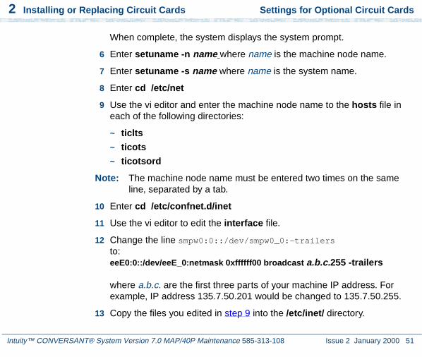
2 Installing or Replacing Circuit Cards Settings for Optional Circuit Cards
Intuity™ CONVERSANT® System Version 7.0 MAP/40P Maintenance 585-313-108 Issue 2 January 2000 51
When complete, the system displays the system prompt.
6 Enter setuname -n name where name is the machine node name.
7 Enter setuname -s name where name is the system name.
8 Enter cd /etc/net
9 Use the vi editor and enter the machine node name to the hosts file in each of the following directories:
~ ticlts
~ ticots
~ ticotsord
Note: The machine node name must be entered two times on the same line, separated by a tab.
10 Enter cd /etc/confnet.d/inet
11 Use the vi editor to edit the interface file.
12 Change the line smpw0:0::/dev/smpw0_0:-trailers to:eeE0:0::/dev/eeE_0:netmask 0xffffff00 broadcast a.b.c.255 -trailers
where a.b.c. are the first three parts of your machine IP address. For example, IP address 135.7.50.201 would be changed to 135.7.50.255.
13 Copy the files you edited in step 9 into the /etc/inet/ directory.

2 Installing or Replacing Circuit Cards Settings for Optional Circuit Cards
Intuity™ CONVERSANT® System Version 7.0 MAP/40P Maintenance 585-313-108 Issue 2 January 2000 52
14 Enter cd /etc/inet
15 Use the vi editor to edit the config file.
16 Change the line ###4c:/usr/sbin/route::n:add default default_router 1
to:4c:/usr/sbin/route::y:add default a.b.c.254 1
where a.b.c. are the first three parts of your IP address. For example, IP address 135.7.50.201 would be changed to 135.7.50.254.
17 Write and exit the file.
18 Continue with the procedure in Verifying the PCI LAN Circuit Card Installation on page 52.
Verifying the PCI LAN Circuit Card Installation
To set the 10 Mbps or 10/100 Mbps PCI LAN circuit card installation, do the following:
1 Enter /etc/inet/rc.restart
2 Check the message log report for TCP/IP or LAN adapter errors. See Chapter 7, “Peripheral Administration,” Intuity CONVERSANT System Version 7.0 Administration, 585-313-501.

2 Installing or Replacing Circuit Cards Settings for Optional Circuit Cards
Intuity™ CONVERSANT® System Version 7.0 MAP/40P Maintenance 585-313-108 Issue 2 January 2000 53
3 Verify that you have network connectivity using the ping command. See Appendix A, “Summary of Commands,” in Intuity CONVERSANT System Version 7.0 Administration, 585-313-501.
Replacing a PCI LAN Circuit Card
To replace a 10Mbps or a 10/100Mbps PCI LAN circuit card, do the following:
1 Run the Hardware Resource Allocator to determine the configuration and slot assignment of the PCI LAN circuit card. See Adding Hardware to an Existing Configuration on page 468 in Appendix A, System Configuration.
2 Record the output.
3 Complete the procedure in Installing the PCI LAN Circuit Card on page 47.
4 Complete the procedure in Verifying the PCI LAN Circuit Card Installation on page 52.
Token Ring Circuit Card
The Intuity CONVERSANT Token Ring circuit card allows you to connect the system to your local area network.

2 Installing or Replacing Circuit Cards Settings for Optional Circuit Cards
Intuity™ CONVERSANT® System Version 7.0 MAP/40P Maintenance 585-313-108 Issue 2 January 2000 54
IBM Turbo 16/4 IBM Turbo 16/4 of the Token Ring circuit card (Figure 27 on page 55) is software configured. This is the latest version of the Token Ring circuit card. A diskette, provided with the Token Ring circuit card, is used to set the IRQ, I/O address, ROM address, RAM address, and RAM size.
Note: If you are installing the IBM Turbo 16/4 circuit card, the system cannot be equipped with the IBM Auto 16/4 circuit card.
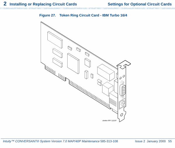
2 Installing or Replacing Circuit Cards Settings for Optional Circuit Cards
Intuity™ CONVERSANT® System Version 7.0 MAP/40P Maintenance 585-313-108 Issue 2 January 2000 55
Figure 27. Token Ring Circuit Card - IBM Turbo 16/4
cdintknr RPY 112197

2 Installing or Replacing Circuit Cards Settings for Optional Circuit Cards
Intuity™ CONVERSANT® System Version 7.0 MAP/40P Maintenance 585-313-108 Issue 2 January 2000 56
To configure the IBM Turbo 16/4 Token Ring circuit card, do the following:
1 If the Token Ring circuit card is being added to the system, run the Intuity CONVERSANT Hardware Resource Allocator to determine the resource assignments. See Operating the Hardware Resource Allocator on page 468 in Appendix A, System Configuration.
Record the parameters listed in Table 2 on page 56.
If the Token Ring circuit card is replacing an existing Token Ring circuit card, record and use the existing hardware resource parameters. You can view the existing parameters by entering cat /etc/conf/sdevice.d/ibmtok
The system displays a message similar to the following message:
ibmtok Y 16 6 1 3 A20 A23 CC000 CDFFF -1ibmtok Y 16 0 0 0 0 0 D0000 D3FFF -1
Table 2. Token Ring Circuit Card Settings
Parameter Setting
IRQ
ROM address
RAM address
I/O address

2 Installing or Replacing Circuit Cards Settings for Optional Circuit Cards
Intuity™ CONVERSANT® System Version 7.0 MAP/40P Maintenance 585-313-108 Issue 2 January 2000 57
Record the parameters listed in Table 2 on page 56.
In the example message, the IRQ is 3, the ROM address range is CC000 - CDFFF, the RAM address range is D0000 - D3FFF, and the I/O address range is A20 - A23.
Verify that IRQ being used by the existing Token Ring circuit card, or designated by the Hardware Resource Allocator, is available.
2 Enter resmgr
The system displays a table containing available and assigned IRQs. Scan the IRQ column to verify availability.
3 Install the new Token Ring circuit card. See Installing a Circuit Card on page 14.
Note: Complete all steps in the installation procedure.
4 Connect the Token Ring circuit card to the LAN.
! CAUTION:Do not use a 10 Base T (802.3) wire to connect the Token Ring circuit card to the LAN.

2 Installing or Replacing Circuit Cards Settings for Optional Circuit Cards
Intuity™ CONVERSANT® System Version 7.0 MAP/40P Maintenance 585-313-108 Issue 2 January 2000 58
Note: You must remove the Tip/Ring circuit card that is set as Tip/Ring 1 (I/0 address=0x200, OSINDEX=1) before completing this procedure (see Removing a Circuit Card on page 12). If you do not have a Tip/Ring circuit card set as Tip/Ring 1, continue withstep 5.
5 Insert the diskette labeled "Turbo Token Ring Setup Floppy" into the diskette drive.
6 Reboot the system. See “Reboot the System,” in “Common System Procedures,” in the Intuity CONVERSANT System Reference, 585-313-205.
The system displays the following message:
Starting PC DOS...
PC DOS 7.0 Startup Menu
1. IBM Auto/Turbo ISA Configuration using LANAID2. IBM Auto/Turbo ISA Extended Diagnostics
Enter a choice: 1 Time Remaining: 15
Note: The system will automatically default to 1 when time remaining is 0.
7 Press ENTER

2 Installing or Replacing Circuit Cards Settings for Optional Circuit Cards
Intuity™ CONVERSANT® System Version 7.0 MAP/40P Maintenance 585-313-108 Issue 2 January 2000 59
The system displays the following message:
If you have a Tip/Ring card equipped (IVP4, IVP6, IVC6, NGTR) that is set as Tip/Ring 1 (I/O address=0x200, OSINDEX=1) you MUST TEMPORARILY REMOVE that Tip/Ring card while running LANAIDC. If equipped, power down the system NOW and remove Tip/Ring card 1. Otherwise, continue with LANAIDC.
Hit any key to continue with LANAIDC...
8 Press ENTER.
The system displays the following message:
Please wait while LANAIDC configures your card. To complete setup, you must assign the INTERRUPT number, RAM address and ROM address. Don’t forget to reinstall Tip/Ring 1 when complete.
Enter LANAIDC parameters - reboot your machine when done.
Examples: /view/help
LANAIDC >
! CAUTION:If n is shown to be 2, enter 9 instead. Do not enter 2.

2 Installing or Replacing Circuit Cards Settings for Optional Circuit Cards
Intuity™ CONVERSANT® System Version 7.0 MAP/40P Maintenance 585-313-108 Issue 2 January 2000 60
9 Enter the following:
/INT=n /ROM=ROM_start_address /RAM=RAM _start_address
where n is the IRQ recorded in Table 2 on page 56, and ROM_start_address and RAM_start_address are addresses recorded in Table 2 on page 56.
The system displays the following message:
Configuration complete:
IBM Turbo/16/4 Token-Ring ISA Adapter
PnP Support: None DetectedAdapter Number: 1Adapter MAC Address: <varies card to card>MicroCode Level: <varies card to card>Serial Number: <varies card to card>Adapter Mode: Auto16 CompatibleConfiguration: LEGACYAdapter State: ActiveI/O Address: A20-A23Interrupt: <n>*RAM Address: <RAM address>ROM Address: <ROM address>Remote IPL: DisabledToken-Ring data rate: 16Auto Sense data rate: Enabled

2 Installing or Replacing Circuit Cards Settings for Optional Circuit Cards
Intuity™ CONVERSANT® System Version 7.0 MAP/40P Maintenance 585-313-108 Issue 2 January 2000 61
Adapter bus width: 16* Setting in conflict
LANAIDC >
Note: The setting in conflict message may or may not appear and can be ignored.
10 Enter /V to view the turbo token ring settings.
The system displays the following message:
...Warning: Interrupt level in conflict.
Configuration complete:
IBM Turbo/16/4 Token-Ring ISA Adapter
PnP Support: None DetectedAdapter Number: 1Adapter MAC Address: <varies card to card>MicroCode Level: <varies card to card>Serial Number: <varies card to card>Adapter Mode: Auto16 CompatibleConfiguration: LEGACYAdapter State: ActiveI/O Address: A20-A23Interrupt: <n>RAM Address: <RAM address>ROM Address: <ROM address>Remote IPL: Disabled

2 Installing or Replacing Circuit Cards Settings for Optional Circuit Cards
Intuity™ CONVERSANT® System Version 7.0 MAP/40P Maintenance 585-313-108 Issue 2 January 2000 62
Token-Ring data rate: 16Auto Sense data rate: EnabledAdapter bus width: 16
LANAIDC >
Record the parameters listed in Table 3 on page 62. These settings are used in the procedures in Installing the Token Ring Driver on page 63.
11 If the configuration is correct, remove the diskette labeled "Turbo Token Ring Setup Floppy" from the diskette drive.
12 Insert the Tip/Ring 1 circuit card if it was removed prior to step 5 (See Installing a Circuit Card on page 14.) Otherwise, continue with step 13.
13 Reboot the system. See “Reboot the System,” in “Common System Procedures,” in the Intuity CONVERSANT System Reference, 585-313-205.
Table 3. Viewed Token Ring Circuit Card Settings
Parameter Setting
I/O address
Interrupt
RAM address

2 Installing or Replacing Circuit Cards Settings for Optional Circuit Cards
Intuity™ CONVERSANT® System Version 7.0 MAP/40P Maintenance 585-313-108 Issue 2 January 2000 63
Installing the Token Ring Driver
To configure the Token Ring driver, do the following:
1 If you are not already logged in as root, do so now.
2 Enter niccfg
The system displays the following message:
Setting up the Network Interface Card Support Utility
The system then displays the Network Interface Card Support Utility—Summary Screen (Figure 26 on page 50).
Note: If other network cards are installed in your system, the system first displays a message indicating network drives are currently installed. Press enter to continue.

2 Installing or Replacing Circuit Cards Settings for Optional Circuit Cards
Intuity™ CONVERSANT® System Version 7.0 MAP/40P Maintenance 585-313-108 Issue 2 January 2000 64
Figure 28. Network Interface Card Support Utility—Summary Screen
3 Use the down arrow to select Add an entry for a card.
4 Press ENTER.
The system displays the Selection Screen (Figure 29 on page 65).
SLOT BUS-NUM BOARD NAME IRQ IO-ADDR MAN-ADDDR DMA----- -------- ---------- ----- -------- --------- --- 6 PCI___0 SMC_EtherPower_9332 IO f880-f8ff fedfec00-fedfec7f
Please Select an Option
( ) Accept all Entries(*) Add an entry for a card( ) Delete/restore an Entry for a Card( ) Install Driver from IHV Diskette( ) Cancel this Utility Without Making Changes
Use the up/down arrow keys to select then press ENTER
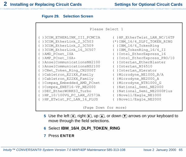
2 Installing or Replacing Circuit Cards Settings for Optional Circuit Cards
Intuity™ CONVERSANT® System Version 7.0 MAP/40P Maintenance 585-313-108 Issue 2 January 2000 65
Figure 29. Selection Screen
5 Use the left , right , up , or down arrows on your keyboard to move through the field selections.
6 Select IBM_16/4_DLPI_TOKEN_RING
7 Press ENTER
Please Select 1
( )3COM_ETHERLINK_III_PCMCIA ( )HP_EtherTwist_LAN_NC/16TP( )3COM_EtherLink_2_3C503 (*)IBM_16/4_DLPI_TOKEN_RING( )3COM_EtherLink_2_3C509 ( )IBM_16/4_TokenRing( )3COM_EtherLink_16_3C507 ( )IBM_TokenRing_16/4_II( )AMD_PCnet_ISA ( )Intel_EtherExpress_16( )AMP_PCnet_ISA+ ( )Intel_EtherExpress_PRO/10( )AnselCommunicationsNH2100 ( )InterLan_EtherBlaster( )AnselCommunicationsNS2100 ( )InterLan_NI6510( )CNet_Token_Ring_CN2000T ( )InterLan_XLerator( )Cabletron_E21XX_Family ( )Microdyne_NE1000_B/A( )Cabletron_E22XX_Family ( )Microdyne_NE2000_A( )Compaq_Embedded_AMD_PCnet ( )Microdyne_NTR1000_G( )Compex_ENET16-VP_NE2000 ( )National_Semi_NE2000( )DEC_EtherWORKS3_Turbo ( )National_Semi_NE2000Plus( )HP_10/100VG_PC_LAN_J2573A ( )Novell/Eagle_NE1000( )HP_ETwist_PC_LAN_16_PLUS ( )Novell/Eagle_NE2000
(Page Down for more)

2 Installing or Replacing Circuit Cards Settings for Optional Circuit Cards
Intuity™ CONVERSANT® System Version 7.0 MAP/40P Maintenance 585-313-108 Issue 2 January 2000 66
The system displays the Configuration Screen (Figure 30 on page 66).
Figure 30. Configuration Screen
! CAUTION:If the IRQ is shown to be 2, enter 9 instead. Do not enter 2.
8 Use F2 (Choices) to select the values for each field. Enter the following:
~ IRQ value from Table 3 on page 62.
~ I/O address from Table 3 on page 62.
~ RAM address from Table 3 on page 62.
9 Press F10 to apply the values and exit.
The system displays the Network Interface Support Card Utility-Summary Screen (Figure 31 on page 67).
Configuring: IBM_16/4_DLPI_TOKEN_RING
IRQ ValueIO AddressRAM Address
Press F2 (Choices) to select values then press F10 to apply and exit.
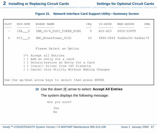
2 Installing or Replacing Circuit Cards Settings for Optional Circuit Cards
Intuity™ CONVERSANT® System Version 7.0 MAP/40P Maintenance 585-313-108 Issue 2 January 2000 67
Figure 31. Network Interface Card Support Utility—Summary Screen
10 Use the down arrow to select: Accept All Entries
The system displays the following message:
Are you sure?
YesNo
SLOT BUS-NUM BOARD NAME IRQ IO-ADDR MAN-ADDDR DMA---- ------- ---------- --- -------- --------- --- - ISA___0 IBM_16/4_DLPI_TOKEN_RING 9 A20-A23 D000-D3FFF
6 PCI___0 SMC_EtherPower_9332 IO f880-f8ff fedfec00-fedfec7f
Please Select an Option
(*) Accept all Entries( ) Add an entry for a card( ) Delete/restore an Entry for a Card( ) Install Driver from IHV Diskette( ) Cancel this Utility Without Making Changes
Use the up/down arrow keys to select then press ENTER
2 Installing or Replacing Circuit Cards Settings for Optional Circuit Cards
Intuity™ CONVERSANT® System Version 7.0 MAP/40P Maintenance 585-313-108 Issue 2 January 2000 68
11 Select yes and press ENTER
The system displays the following message:
Installing drivers for the Network Card(s) you selected. This will take a few minutes.
12 Reboot the system. See “Reboot the System,” in “Common System Procedures,” in the Intuity CONVERSANT System Reference, 585-313-205.
The system displays the system prompt.
Asynchronous SuperSerial Card
The asynchronous circuit card allows you to connect the Intuity CONVERSANT System to external peripheral equipment. One end of the octopus cable, shipped with the circuit card, connects to the circuit card faceplate. The other end splits into eight separate cables, allowing for eight connections to your system.
Figure 32 on page 69 shows the asynchronous SuperSerial circuit card.
Note: If you are installing the asynchronous SuperSerial circuit card, the system cannot be equipped with the 8-Port Asynchronous Megaport circuit card.

2 Installing or Replacing Circuit Cards Settings for Optional Circuit Cards
Intuity™ CONVERSANT® System Version 7.0 MAP/40P Maintenance 585-313-108 Issue 2 January 2000 69
Figure 32. Asynchronous SuperSerial Circuit Card
cdineqnx RPY 122997
2 Installing or Replacing Circuit Cards Settings for Optional Circuit Cards
Intuity™ CONVERSANT® System Version 7.0 MAP/40P Maintenance 585-313-108 Issue 2 January 2000 70
Installing the Asynchronous SuperSerial Card Driver
To install the Asynchronous SuperSerial card driver, do the following:
1 If you are not already logged in as root, do so now.
2 Enter pkgadd -d diskette1
The system displays the following message:
Insert diskette into Floppy Drive 1.Type [go] when ready,
or [q] to quit: (default: go)
3 Insert the diskette labeled “Equinox SST Loadable STREAMS Device Driver (EISA/ISA/MCA/PCI) 1 of 1” into the diskette drive.
4 Press ENTER.
The system displays the following message:
Installation in progress -- do not remove the diskette.
The following packages are available: 1. eqn Equinox SST Loadable STREAMS
Device Driver (EISA/ISA/MCA/PCI)(i386)
Select package(s) you wish to process (or ‘all’ to process all packages). (default: all) [?,??,q]:
5 Press ENTER.

2 Installing or Replacing Circuit Cards Settings for Optional Circuit Cards
Intuity™ CONVERSANT® System Version 7.0 MAP/40P Maintenance 585-313-108 Issue 2 January 2000 71
The system displays the following message:
PROCESSING:Package: Equinox SST Loadable STREAMS Device Driver (EISA/ISA/MCA/PCI) (eqn) from <diskette1>
Equinox SST Loadable STREAMS Device Driver(EISA/ISA/MCA/PCI) (i386)Using </> as the package base directory.Lucent Technologies Inc.
The system displays several status messages and then the following message:
This seems to be an ISA system. Is this correct[Y/n]?
6 Enter y
The system displays the following message:
Installing for ISA bus system.
The following i/o ports appear to be free for use by Equinox ISA boards:
220 240 260 280 2a0 2c0 2e0 320 360 3a0 3c0Should the driver autoconfigure all Equinox ISA boards [Y/n]?
7 Enter n

2 Installing or Replacing Circuit Cards Settings for Optional Circuit Cards
Intuity™ CONVERSANT® System Version 7.0 MAP/40P Maintenance 585-313-108 Issue 2 January 2000 72
The system displays the following message:
One 16k block of memory addresses will be used by all Equinox ISA boards. This address must meet the following criteria:
1. In the range of 640 kilobyte to 1 Megabyte or above 2 Gigabytes
2. No other physical memory (RAM/ROM) present3. Must NOT be cached4. Must begin on a 16k boundary
An example hexadecimal address is 0xb0000
Enter your address selection in hexadecimal: 0x
8 Enter the appropriate address as determined by the Hardware Resource Allocator.
The memory block boundary is determined by the Intuity CONVERSANT Hardware Resource Allocator. See Operating the Hardware Resource Allocator on page 468 in Appendix A, System Configuration.
The system displays the following message:
You may enable a selection of baud rates above 38400 for all ports by answering "Yes" to the following question.
If you enable baud rates above 38400, speeds below 300 baud will be unavailable. Speeds 300 to 38400 are unaffected.

2 Installing or Replacing Circuit Cards Settings for Optional Circuit Cards
Intuity™ CONVERSANT® System Version 7.0 MAP/40P Maintenance 585-313-108 Issue 2 January 2000 73
The high baud rates are selected according to the following table:
57600 B5076800 B75115200 B110238400 B134 (depending on board/module
(type
Enable high baud rate selection [y/N]?
9 Enter n
The system displays the following message:
The unix kernel will be rebuilt to include your configuration changes during the next system reboot.
A system rebuild has been requested when the system is shutdown. System tunables have been modified.
Please request a reboot using the "init 6" command to use the driver.
If you desire the default set of port monitors and port services to be installed, execute "/etc/equportsetup" after the system has rebooted.
Installation of Equinox SST Loadable STREAMS Device Driver (EISA/ISA/MCA/PCI) (equ) was successful.

2 Installing or Replacing Circuit Cards Settings for Optional Circuit Cards
Intuity™ CONVERSANT® System Version 7.0 MAP/40P Maintenance 585-313-108 Issue 2 January 2000 74
Insert diskette into Floppy Drive 1.Type [go] when ready,
or [q] to quit: (default: go)
10 Enter q
11 Remove the diskette labeled “Equinox SST Loadable STREAMS Device Driver (EISA/ISA/MCA/PCI) 1 of 1” from the diskette drive.
12 Reboot the system. See “Reboot the System,” in “Common System Procedures,” in the Intuity CONVERSANT System Reference, 585-313-205.
FIFO/SIB Synchronous Host Circuit Card
The MAP/40P supports up to two Lucent FIFO/SIB synchronous host circuit cards.
Figure 33 on page 75 shows the FIFO/SIB synchronous host card and the location of the switches and interrupt jumpers.

2 Installing or Replacing Circuit Cards Settings for Optional Circuit Cards
Intuity™ CONVERSANT® System Version 7.0 MAP/40P Maintenance 585-313-108 Issue 2 January 2000 75
Figure 33. FIFO/SIB Synchronous Host Circuit Card
SW1(see Synchronous Hostswitch setting figure)
J3(see Synchronous Hostjumper setting figure)
J2(see Synchronous Hostjumper setting figure)
2 Installing or Replacing Circuit Cards Settings for Optional Circuit Cards
Intuity™ CONVERSANT® System Version 7.0 MAP/40P Maintenance 585-313-108 Issue 2 January 2000 76
Jumper Settings There are two jumper locations on the synchronous host circuit card, J3 and J2.
Use J3 to set the interrupt request line (IRQ) to a value of 3, 5, 9, 10, 11, 12, or 13 (Figure 34 on page 77). The IRQ corresponds to the number below the pins. Figure 34 on page 77 shows the card set with an IRQ of 3. See Operating the Hardware Resource Allocator on page 468 in Appendix A, System Configuration.
Note: If you are using IRQ 9, ensure that IRQ 2 is unused on your system.
J2 is preset at the factory. However, before you install the FIFO/SIB synchronous host circuit card, ensure that this jumper is set as shown in Figure 34 on page 77.
Note: When operating at 64 kbaud, this setting supports a maximum cable length of 15 ft.
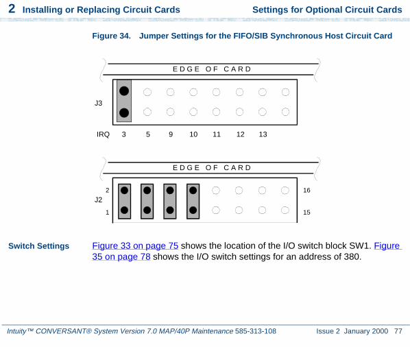
2 Installing or Replacing Circuit Cards Settings for Optional Circuit Cards
Intuity™ CONVERSANT® System Version 7.0 MAP/40P Maintenance 585-313-108 Issue 2 January 2000 77
Figure 34. Jumper Settings for the FIFO/SIB Synchronous Host Circuit Card
Switch Settings Figure 33 on page 75 shows the location of the I/O switch block SW1. Figure 35 on page 78 shows the I/O switch settings for an address of 380.
J3
J2
E D G E O F C A R D
E D G E O F C A R D
2
1
16
15
IRQ 3 5 9 10 11 12 13

2 Installing or Replacing Circuit Cards Settings for Optional Circuit Cards
Intuity™ CONVERSANT® System Version 7.0 MAP/40P Maintenance 585-313-108 Issue 2 January 2000 78
Figure 35. Switch Settings for the FIFO/SIB Synchronous Host Circuit Card
Table 4 on page 78 shows the switch settings for other potential I/O addresses.
Table 4. FIFO/SIB Switch Settings
Switch
I/O Address 1 2 3
250 On On Off
260 Off Off On1 of 2
Base I/O address = 380 Hex
All switches closed or OFF
NOTE: Switch 4 is not used.

2 Installing or Replacing Circuit Cards Standard Circuit Cards
Intuity™ CONVERSANT® System Version 7.0 MAP/40P Maintenance 585-313-108 Issue 2 January 2000 79
Standard Circuit Cards
! CAUTION:Observe proper electrostatic discharge precautions when you handle computer components. Wear an antistatic wrist strap that touches your bare skin and connect the strap cable to an earth ground. See Protecting Against Damage from Electrostatic Discharge on page 2 in Chapter 1, Getting Inside the Computer for detailed electrostatic discharge precautions.
2B0 On Off On
2E0 Off On On
380 (default) Off Off Off
3A0 On Off Off
3E0 Off On Off
Disabled On On On
Table 4. FIFO/SIB Switch Settings
Switch
I/O Address 1 2 3
2 of 2

2 Installing or Replacing Circuit Cards Standard Circuit Cards
Intuity™ CONVERSANT® System Version 7.0 MAP/40P Maintenance 585-313-108 Issue 2 January 2000 80
This section provides the following information on the standard circuit cards that are included with every MAP/40P:
• Switch and jumper settings
• Other installation requirements that are specific to the particular circuit card you are installing
P5 200 MHz CPU Circuit Card
The P5 200 MHz CPU is packaged on a single PC/AT-compatible circuit card (Figure 36 on page 81) that plugs into the backplane. There is one P5 200 MHz CPU circuit card installed in the MAP/40P.
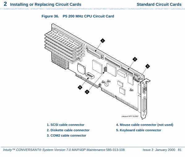
2 Installing or Replacing Circuit Cards Standard Circuit Cards
Intuity™ CONVERSANT® System Version 7.0 MAP/40P Maintenance 585-313-108 Issue 2 January 2000 81
Figure 36. P5 200 MHz CPU Circuit Card
cdinpent RPY 012897
1
2
3
4
5
1. SCSI cable connector
2. Diskette cable connector
3. COM2 cable connector
4. Mouse cable connector (not used)
5. Keyboard cable connector

2 Installing or Replacing Circuit Cards Standard Circuit Cards
Intuity™ CONVERSANT® System Version 7.0 MAP/40P Maintenance 585-313-108 Issue 2 January 2000 82
Setting the Resource Options
The resource options for the P5 200 MHz CPU circuit card are set by jumpers and switches.
Jumper Settings
The P5 200 MHz CPU card has jumpers that you must verify before you install the circuit card (Figure 37 on page 83).
Switch Settings
The P5 200 MHz CPU card has switches that you must set before you install the circuit card (Figure 37 on page 83).
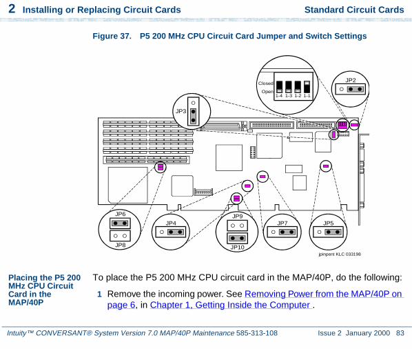
2 Installing or Replacing Circuit Cards Standard Circuit Cards
Intuity™ CONVERSANT® System Version 7.0 MAP/40P Maintenance 585-313-108 Issue 2 January 2000 83
Figure 37. P5 200 MHz CPU Circuit Card Jumper and Switch Settings
Placing the P5 200 MHz CPU Circuit Card in the MAP/40P
To place the P5 200 MHz CPU circuit card in the MAP/40P, do the following:
1 Remove the incoming power. See Removing Power from the MAP/40P on page 6, in Chapter 1, Getting Inside the Computer .
jpinpent KLC 033198
JP6
JP8
JP9JP7 JP5
JP2
JP10
JP4
Closed
Open1-4 1-3 1-2 1-1
JP3

2 Installing or Replacing Circuit Cards Standard Circuit Cards
Intuity™ CONVERSANT® System Version 7.0 MAP/40P Maintenance 585-313-108 Issue 2 January 2000 84
2 Remove the dress cover. See Removing the Dress Cover on page 9, in Chapter 1, Getting Inside the Computer .
3 Remove the video controller card. See Removing a Circuit Card on page 12.
4 Attach the SCSI cable adapter to the P5 200 MHz CPU circuit card (Figure 38 on page 85).

2 Installing or Replacing Circuit Cards Standard Circuit Cards
Intuity™ CONVERSANT® System Version 7.0 MAP/40P Maintenance 585-313-108 Issue 2 January 2000 85
Figure 38. Attaching the SCSI Cable Adapter
cdinpnt2 RPY 012897
1
2
1. SCSI cable adapter 2. SCSI cable connector

2 Installing or Replacing Circuit Cards Standard Circuit Cards
Intuity™ CONVERSANT® System Version 7.0 MAP/40P Maintenance 585-313-108 Issue 2 January 2000 86
5 Complete step 1 and step 2 of the procedure in Installing a Circuit Card on page 14.
6 Attach the keyboard cable to the keyboard pins on the P5 200 MHz CPU circuit card. See Inserting the Remote Maintenance Circuit Card on page 112.
7 Complete step 3 of the procedure in Installing a Circuit Card on page 14.
8 Attach the disk activity cable to the P5 200 MHz CPU circuit card with the red lead toward the back of the MAP/40P.
9 Install the rear COM2 cable to the P5 200 MHz CPU circuit card. See Inserting the Remote Maintenance Circuit Card on page 112.
10 Attach the SCSI cable to the SCSI controller pins on the P5 200 MHz CPU circuit card. See Installing a SCSI Cable on page 196 in Chapter 4, Replacing Other Components ,.
Note: The SCSI cable has a label that displays the following message:
H600-449 Group 1MAP/40P SCSI CA(SCSI/( ) -P5/200)
Note: The SCSI cable will be routed over top of the disk activity cable.
11 Attach the diskette drive cable to the diskette drive cable pins on the P5 200 MHz CPU circuit card. See Installing a Diskette Cable on page 188 .

2 Installing or Replacing Circuit Cards Standard Circuit Cards
Intuity™ CONVERSANT® System Version 7.0 MAP/40P Maintenance 585-313-108 Issue 2 January 2000 87
Note: The diskette drive cable has a label that displays the following message:
H600-449 Group 1MAP/40P Floppy CA(Floppy/( ) -P5/200)
Note: Replace the video controller circuit card. See Installing a Circuit Card on page 14.
12 Complete step 4 through step 10 in Installing a Circuit Card on page 14.
Verifying the Parameter Settings
P5 200 MHz CPU circuit card parameter settings are preloaded into each card. To verify these settings, do the following.
Host Adapter Parameter Settings
! CAUTION:Do not change the settings if there is a mismatch. Contact your remote maintenance center for assistance.
1 Reboot the system. See “Reboot the System,” in “Common System Procedures,” in the Intuity CONVERSANT System Reference, 585-313-205.
2 After the power on self test (POST) but before the system boots, press CONTROL + A when prompted.

2 Installing or Replacing Circuit Cards Standard Circuit Cards
Intuity™ CONVERSANT® System Version 7.0 MAP/40P Maintenance 585-313-108 Issue 2 January 2000 88
The system displays the Host Adapter Configuration screen (Figure 39 on page 88).
Figure 39. Host Adapter Configuration Screen
3 Place the cursor on Configure/View Host Adapter Settings. Use the up and down arrows to move the cursor.
4 Press ENTER.
5 Compare the settings shown on the screen with the parameters listed in Table 5 on page 89.
Would you like to configure the Host Adapter, or run the SCSI disk utilities? Select the option and press <Enter>. Press <F5> to switch between color and monochrome modes.
OptionsConfigure/View Host Adapter Settings
SCSI Disk Utilities
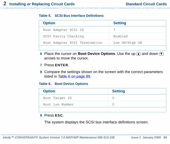
2 Installing or Replacing Circuit Cards Standard Circuit Cards
Intuity™ CONVERSANT® System Version 7.0 MAP/40P Maintenance 585-313-108 Issue 2 January 2000 89
6 Place the cursor on Boot Device Options. Use the up and down arrows to move the cursor.
7 Press ENTER.
8 Compare the settings shown on the screen with the correct parameters listed in Table 6 on page 89.
9 Press ESC.
The system displays the SCSI bus interface definitions screen.
Table 5. SCSI Bus Interface Definitions
Option Setting
Host Adapter SCSI ID 7
SCSI Parity Checking Enabled
Host Adapter SCSI Termination Low ON/High ON
Table 6. Boot Device Options
Option Setting
Boot Target ID 0
Boot Lun Number 0
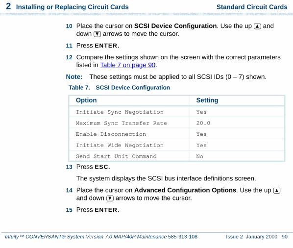
2 Installing or Replacing Circuit Cards Standard Circuit Cards
Intuity™ CONVERSANT® System Version 7.0 MAP/40P Maintenance 585-313-108 Issue 2 January 2000 90
10 Place the cursor on SCSI Device Configuration. Use the up and down arrows to move the cursor.
11 Press ENTER.
12 Compare the settings shown on the screen with the correct parameters listed in Table 7 on page 90.
Note: These settings must be applied to all SCSI IDs (0 – 7) shown.
13 Press ESC.
The system displays the SCSI bus interface definitions screen.
14 Place the cursor on Advanced Configuration Options. Use the up and down arrows to move the cursor.
15 Press ENTER.
Table 7. SCSI Device Configuration
Option Setting
Initiate Sync Negotiation Yes
Maximum Sync Transfer Rate 20.0
Enable Disconnection Yes
Initiate Wide Negotiation Yes
Send Start Unit Command No

2 Installing or Replacing Circuit Cards Standard Circuit Cards
Intuity™ CONVERSANT® System Version 7.0 MAP/40P Maintenance 585-313-108 Issue 2 January 2000 91
16 Compare the settings shown on the screen with the correct parameters listed in Table 8 on page 91.
17 Press ESC.
The system displays the SCSI bus interface definitions screen.
18 Press ESC.
The system displays the following message:
Exit UtilitiesYesNo
Table 8. Advanced Configuration Options
Option Setting
Host Adapter BIOS Enabled
Support Removable Disks Boot Only
Extended BIOS Translation Disabled
Display <Ctrl-A> Message Enabled
Multiple Lun Support Disabled
BIOS Support for More Enabled

2 Installing or Replacing Circuit Cards CMOS Parameter Settings
Intuity™ CONVERSANT® System Version 7.0 MAP/40P Maintenance 585-313-108 Issue 2 January 2000 92
19 Place the cursor on Yes. Use the up and down arrows to move the cursor.
20 Press ENTER.
The system displays the following message:
Please press any key to reboot.
21 Press ENTER.
The system reboots and responds with the UNIX prompt (#).
CMOS Parameter Settings
! CAUTION:Do not change the settings if there is a mismatch. Contact your local technical support representative for assistance.
1 Perform a hard reboot of the system. See “Reboot the System,” in “Common System Procedures,” in the Intuity CONVERSANT System Reference, 585-313-205.
2 During the POST, press S.
The system displays the following message:
Please standby for SETUP Utility...

2 Installing or Replacing Circuit Cards CMOS Parameter Settings
Intuity™ CONVERSANT® System Version 7.0 MAP/40P Maintenance 585-313-108 Issue 2 January 2000 93
After the system has installed the BIOS it displays the CMOS basic options set-up menu.
3 Compare the P5 200 MHz CPU circuit card settings in the setup menu with the default parameters listed in Table 9 on page 94.
Note: The settings shown are for BIOS Version 4.05a.2.2 only.
Note: The settings in Table 9 on page 94 that are indicated by a star (*) may differ from the default parameters due to other equipped feature circuit cards in your system. All other settings should be the same as those listed.
Note: ISA option ROMs such as those on the remote maintenance circuit card reside at addresses D000, D400, D800, and DC00 under Shadow RAM. When equipped, these devices should not be shadowed.

2 Installing or Replacing Circuit Cards CMOS Parameter Settings
Intuity™ CONVERSANT® System Version 7.0 MAP/40P Maintenance 585-313-108 Issue 2 January 2000 94
Table 9. CMOS Basic Option Settings for the P5 200 MHz CPU Circuit Card
Option Setting
Time and Date
Set the time and date to the current time and date.
Floppy Disks
Floppy Controller Enabled
Select Drive A: Type 3.5 Inch, 1.44 MB
Select Drive B: Type Not Installed
Floppy Seek during POST Enabled
Fixed Disks
IDE Controller Setup Disabled
Auto Detect IDE Drives Enabled
Large Disk DOS Compatible Disabled
Keyboard
Keyboard Typematic Sound Enabled
Keyboard Typematic Delay 500 msec
Keyboard Typematic Rate 15 chars/sec
1 of 3

2 Installing or Replacing Circuit Cards CMOS Parameter Settings
Intuity™ CONVERSANT® System Version 7.0 MAP/40P Maintenance 585-313-108 Issue 2 January 2000 95
Shadow RAM
Shadow Select C000:0 32K SHADOW (*)
Shadow Select C800:0 12K SHADOW (*)
Shadow Select CC00:0 AVAILABLE (*)
Shadow Select D000:0 AVAILABLE (*)
Note: If this line indicates SHADOW, change it to ROM.
Shadow Select D400:0 2K ROM (*)
Note: If this line indicates SHADOW, change it to ROM.
Shadow Select D800:0 AVAILABLE (*)
Note: If this line indicates SHADOW, change it to ROM.
Table 9. CMOS Basic Option Settings for the P5 200 MHz CPU Circuit Card
Option Setting
2 of 3

2 Installing or Replacing Circuit Cards CMOS Parameter Settings
Intuity™ CONVERSANT® System Version 7.0 MAP/40P Maintenance 585-313-108 Issue 2 January 2000 96
Shadow Select DC00:0 7K AVAILABLE (*)
Note: If this line indicates SHADOW, change it to ROM.
Shadow Select E000:0 64K SHADOW
Shadow Select F000:0 64K SHADOW
Boot Options
101-Key Keyboard Numlock at Boot Enabled
Set Boot Drive Sequence Diskette, Hard, CD-ROM Drives
Report POST Errors Enabled
Report Option ROM Errors Disabled
Show F2 Message for Setup Enabled
Quiet Boot Enable/Disable Enabled
Password Edit
Password Options Disabled
Table 9. CMOS Basic Option Settings for the P5 200 MHz CPU Circuit Card
Option Setting
3 of 3

2 Installing or Replacing Circuit Cards CMOS Parameter Settings
Intuity™ CONVERSANT® System Version 7.0 MAP/40P Maintenance 585-313-108 Issue 2 January 2000 97
4 To change the parameter settings, do the following:
a Place the cursor on the appropriate heading. Use the up and down arrows to move the cursor.
b Press ENTER.
c Change the parameters. Use the up and down arrows to move the cursor.
d Press ENTER.
5 Place the cursor on Advanced Options.
6 Press ENTER.
The system displays the CMOS advanced options set-up menu.
7 Compare the P5 200 MHz CPU circuit card settings in the set-up menu with the default parameters listed in Table 9 on page 94.
Note: The settings in Table 10 on page 98 that are indicated by a star (*) may differ from the default parameters due to other equipped feature circuit cards in your system.

2 Installing or Replacing Circuit Cards CMOS Parameter Settings
Intuity™ CONVERSANT® System Version 7.0 MAP/40P Maintenance 585-313-108 Issue 2 January 2000 98
Table 10. CMOS Advanced Option Settings for the P5 200 MHz CPU Circuit Card
Option Setting
Serial Ports
16550 Compatible UART 1: 03F8h, IRQ4 (*)
Note: Disable this port if the hardware resource allocator assigned the remote maintenance circuit card here.
16550 Compatible UART 2: 02F8h, IRQ3 (*)
Note: Disable this port if the hardware resource allocator assigned the remote maintenance circuit card here.
Parallel Ports
Select Parallel Port Address: 0378h IRQ 7
Parallel Port Mode AT Compatible
Redirection
Select Redirection Destination Disabled
1 of 3

2 Installing or Replacing Circuit Cards CMOS Parameter Settings
Intuity™ CONVERSANT® System Version 7.0 MAP/40P Maintenance 585-313-108 Issue 2 January 2000 99
Memory Cache
External Cache Enabled
Advanced Chipset
DRAM Speed 70ns
DMA Alias Disabled
ECC/Parity Configuration ECC
Memory Gap Block Size Disabled
I/O Recovery
8 bit I/O Recovery Time 6.5 SYSCLK
16 bit I/O Recovery Time 6.5 SYSCLK
ISA Guaranteed Access Time Disabled
Delayed Transactions Enabled
Bus Speed
ISA Bus Speed 8.25 MHz
Table 10. CMOS Advanced Option Settings for the P5 200 MHz CPU Circuit Card
Option Setting
2 of 3

2 Installing or Replacing Circuit Cards CMOS Parameter Settings
Intuity™ CONVERSANT® System Version 7.0 MAP/40P Maintenance 585-313-108 Issue 2 January 2000 100
8 To change the parameter settings, do the following.
a Place the cursor on the appropriate heading. Use the up and down arrows to move the cursor.
b Press ENTER.
c Change the parameters. Use the up and down arrows to move the cursor.
d Press ENTER.
9 Place the cursor on PCI Options.
10 Press ENTER.
Miscellaneous
SPEAKER Configuration Enabled
Watchdog Timer Delay: 1.2 sec
Allocate USB Resources Disabled
PS2 Mouse
PS2MOUSE Configuration Disabled
Table 10. CMOS Advanced Option Settings for the P5 200 MHz CPU Circuit Card
Option Setting
3 of 3

2 Installing or Replacing Circuit Cards CMOS Parameter Settings
Intuity™ CONVERSANT® System Version 7.0 MAP/40P Maintenance 585-313-108 Issue 2 January 2000 101
The system displays the CMOS PCI options set-up menu.
11 Compare the P5 200 MHz CPU circuit card settings in the set-up menu with the default parameters listed in Table 11 on page 101.
Note: The settings in Table 11 on page 101 that are indicated by a star (*) may differ from the default parameters due to other equipped feature circuit cards in your system.
Table 11. CMOS PCI Option Settings for the P5 200 MHz CPU Circuit Card
Option Setting
IRQs Setup
PCI IRQ Line1 IRQ14
PCI IRQ Line2 IRQ14
PCI IRQ Line3 IRQ10
PCI IRQ Line4 IRQ10
PCI Devices
0x8086/0x1250 Bridge-Host No IRQ
0x9004/0x7078 MassStorage-SCSI INTA->IRQ14
0x8086/0x7000 Bridge-ISA No IRQ
0x8086/0x7010 MassStorage-IDE No IRQ
1 of 3
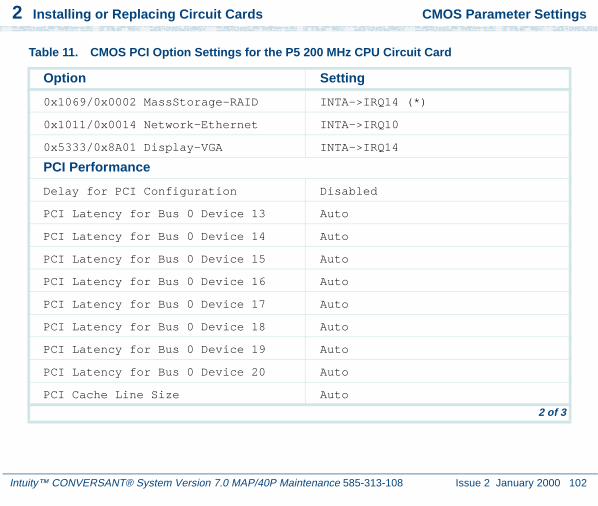
2 Installing or Replacing Circuit Cards CMOS Parameter Settings
Intuity™ CONVERSANT® System Version 7.0 MAP/40P Maintenance 585-313-108 Issue 2 January 2000 102
0x1069/0x0002 MassStorage-RAID INTA->IRQ14 (*)
0x1011/0x0014 Network-Ethernet INTA->IRQ10
0x5333/0x8A01 Display-VGA INTA->IRQ14
PCI Performance
Delay for PCI Configuration Disabled
PCI Latency for Bus 0 Device 13 Auto
PCI Latency for Bus 0 Device 14 Auto
PCI Latency for Bus 0 Device 15 Auto
PCI Latency for Bus 0 Device 16 Auto
PCI Latency for Bus 0 Device 17 Auto
PCI Latency for Bus 0 Device 18 Auto
PCI Latency for Bus 0 Device 19 Auto
PCI Latency for Bus 0 Device 20 Auto
PCI Cache Line Size Auto
Table 11. CMOS PCI Option Settings for the P5 200 MHz CPU Circuit Card
Option Setting
2 of 3

2 Installing or Replacing Circuit Cards CMOS Parameter Settings
Intuity™ CONVERSANT® System Version 7.0 MAP/40P Maintenance 585-313-108 Issue 2 January 2000 103
12 Place the cursor on Basic Options.
13 Press ENTER.
The system displays the CMOS basic options set-up menu.
a If you have changed any option from what is indicated in Table 9 on page 94, Table 10 on page 98, and Table 11 on page 101, press ESC.
This will reboot the system using the values you entered without creating a Flash it backup. If you have entered any incorrect values you can still go back to the original CMOS settings.
If you are certain the CMOS settings are correct and that the system will operate properly, place the cursor on Flash It! and press ENTER .
The system displays the following message.
Ready to Flash, Press the ESC key to Exit or ENTER to flash.
Onboard SCSI
Onboard PCI SCSI Enabled
Table 11. CMOS PCI Option Settings for the P5 200 MHz CPU Circuit Card
Option Setting
3 of 3

2 Installing or Replacing Circuit Cards CMOS Parameter Settings
Intuity™ CONVERSANT® System Version 7.0 MAP/40P Maintenance 585-313-108 Issue 2 January 2000 104
Note: CMOS options can not be flashed if you made any changes. If any changes were made, you must exit, reboot, then re-enter setup to flash.
b Press ENTER.
The system displays the following message.
Erasing CPU BIOSFlash It Reset in progress.
After approximately three minutes, the system reboots and displays Console Login:
Video Controller Circuit Cards
Note: The AT&T CRT345 monitor is not compatible with the PCI video circuit card.
Figure 40 on page 105 and Figure 41 on page 106 show the PCI video controller circuit cards.
Note: There are no jumpers to set on the PCI video circuit cards.

2 Installing or Replacing Circuit Cards CMOS Parameter Settings
Intuity™ CONVERSANT® System Version 7.0 MAP/40P Maintenance 585-313-108 Issue 2 January 2000 105
Figure 40. PCI Video Controller Circuit Card
cdinpvid RPY 071697

2 Installing or Replacing Circuit Cards CMOS Parameter Settings
Intuity™ CONVERSANT® System Version 7.0 MAP/40P Maintenance 585-313-108 Issue 2 January 2000 106
Figure 41. PCI Video Controller Circuit Card
LNK
DATA
ACT100TX
INTEL
PRO
/100
cdixpro LJK 021299

2 Installing or Replacing Circuit Cards Remote Maintenance Circuit Card
Intuity™ CONVERSANT® System Version 7.0 MAP/40P Maintenance 585-313-108 Issue 2 January 2000 107
Remote Maintenance Circuit Card
The remote maintenance circuit card provides remote diagnostics of basic components (Figure 42 on page 108). There is one remote maintenance circuit card installed on the system.

2 Installing or Replacing Circuit Cards Remote Maintenance Circuit Card
Intuity™ CONVERSANT® System Version 7.0 MAP/40P Maintenance 585-313-108 Issue 2 January 2000 108
Figure 42. Remote Maintenance Circuit Card
cdr2rmb LJK 043097
UPSconnector
Fan statusconnector
BECenableswitch
Platformreset
connector
Factoryuse only

2 Installing or Replacing Circuit Cards Remote Maintenance Circuit Card
Intuity™ CONVERSANT® System Version 7.0 MAP/40P Maintenance 585-313-108 Issue 2 January 2000 109
Types of Remote Maintenance Circuit Cards
The Lucent Intuity system supports the AYC54 remote maintenance circuit card.
• With an internal modem (AYC54)
• Without an internal modem (AYC55)
You can determine the type of remote maintenance circuit card installed on you system by viewing the faceplate. Figure 43 on page 110 shows the faceplate of a remote maintenance circuit card with an internal modem (AYC54).
Note: The AYC54 and AYC55 remote maintenance circuit cards can be connected to an external modem.

2 Installing or Replacing Circuit Cards Remote Maintenance Circuit Card
Intuity™ CONVERSANT® System Version 7.0 MAP/40P Maintenance 585-313-108 Issue 2 January 2000 110
Figure 43. AYC54 Remote Maintenance Circuit Card Faceplate
Lock-down screws
RMB reset switch
RMB AYC54 label
RJ-11 tip-ringconnector (line in)
User-definableoutput
User-definable input(external UPS)
UART DB9Sconnector
fpr2rmb2 LJK 041597
LINE
OUTUART
RESETIN
Rem
ote
Mai
nten
anc
eB
oard
AY
C54
Lucent

2 Installing or Replacing Circuit Cards Remote Maintenance Circuit Card
Intuity™ CONVERSANT® System Version 7.0 MAP/40P Maintenance 585-313-108 Issue 2 January 2000 111
Figure 44 on page 111 shows the faceplate of a remote maintenance circuit card without an internal modem (AYC55).
Figure 44. AYC55 Remote Maintenance Circuit Card Faceplate
Lock-down screws
RMB reset switch
RMB AYC55 label
User-definableoutput
User-definable input(external UPS)
UART DB9Sconnector
fpr2rmb3 LJK 043097
OUTUART
RESETIN
Rem
ote
Mai
nten
ance
Boa
rdAYC
55
Lucent

2 Installing or Replacing Circuit Cards Remote Maintenance Circuit Card
Intuity™ CONVERSANT® System Version 7.0 MAP/40P Maintenance 585-313-108 Issue 2 January 2000 112
Setting the Resource Options
The remote maintenance circuit card is equipped with a BEC enable switch (Figure 42 on page 108). Ensure that this switch is set to the ON position (Figure 45 on page 112).
Figure 45. BEC Enable Switch
Inserting the Remote Maintenance Circuit Card
To insert the remote maintenance circuit card, do the following:
1 Complete the steps in Installing a Circuit Card on page 14.
2 Connect the remote maintenance circuit card interface cable to the P5 200 MHz CPU circuit card keyboard connection (Figure 36 on page 81).
Note: The P5 200 MHz CPU circuit card must be pulled partially out of the MAP/40P before the cable can be connected to the keyboard port.
3 Connect the remote maintenance circuit card interface cable to the P5 200 MHz CPU circuit card COM2 port connection (Figure 36 on page 81).
4 Connect the remote maintenance circuit card interface cable to the remote maintenance circuit card platform reset connection (Figure 42 on page 108).
ON 1
swr2bec LJK 063097

2 Installing or Replacing Circuit Cards Remote Maintenance Circuit Card
Intuity™ CONVERSANT® System Version 7.0 MAP/40P Maintenance 585-313-108 Issue 2 January 2000 113
5 Connect the remote maintenance circuit card interface cable to the remote maintenance circuit card fan status connection (Figure 42 on page 108).
Installing the Remote Maintenance Circuit Card Software Package
To install the remote maintenance circuit card software package, do the following:
1 Stop the voice system.
2 Enter pkgadd -d ctape1
The system displays the following message:
Insert a cartridge into Tape Drive 1.Type [go] when ready,
or [q] to quit: (default:go)
3 Insert the tape labeled “RMB Software Set” into the tape drive.
4 Press ENTER.
The system displays the following message:
Installation in progress. Do not remote the cartridge tape.
The following sets are available: 1 RMBset INTUITY RMB V2 Set
(i486)
Select package(s) you wish to process (or ‘all’ to process all packages). (default: all) [?,??,q]

2 Installing or Replacing Circuit Cards Remote Maintenance Circuit Card
Intuity™ CONVERSANT® System Version 7.0 MAP/40P Maintenance 585-313-108 Issue 2 January 2000 114
5 Press ENTER.
The system displays the following message:
Processing:
Set: RMB Software Set R2.0 (RMBset) from <ctape1>.
Intuity RMB Software Set R2.0(i486)Using </> as the package base directory.
The RMB BEC ADDR has been defaulted to D1000
As is typical, should the RMB use COM1, rather than COM2 (default:y) [y,n,?]:
6 If the remote maintenance circuit card should use:
~ COM1, press ENTER .
~ COM2, enter n
The system displays the following message:
Please select the country code:
01 - United States02 - International
Country code [01]:
7 Enter the appropriate code.

2 Installing or Replacing Circuit Cards Remote Maintenance Circuit Card
Intuity™ CONVERSANT® System Version 7.0 MAP/40P Maintenance 585-313-108 Issue 2 January 2000 115
The system displays the following message:
Insert a cartridge into Tape Drive 1.Type [go] when ready
or [q] to quit: (default: go)
8 Enter q
9 Remove the cartridge tape.

Intuity™ CONVERSANT® System Version 7.0 MAP/40P Maintenance 585-313-108 Issue 2 January 2000 116
3 Replacing the Hard Disk Drive
Overview
This chapter describes the procedures to identify and recover from Intuity CONVERSANT system hard disk drive failures, to add a hard disk drive, and to clean a hard disk drive.
Topics covered include:
• How to identify a failed hard disk drive
• Hardware procedures for replacing a hard disk drive
• Software procedures for preparing the system for a new hard disk drive
• Software procedures for initializing a hard disk drive

3 Replacing the Hard Disk Drive Identifying a Failed Hard Disk Drive
Intuity™ CONVERSANT® System Version 7.0 MAP/40P Maintenance 585-313-108 Issue 2 January 2000 117
Identifying a Failed Hard Disk Drive
Before a hard disk drive can be replaced you must identify which drive has failed. This section tells how to identify a failed hard disk drive in systems with two hard disk drives (both mirrored and unmirrored).
Note: If your system is configured with only one hard disk drive, see Software and Hardware Procedures for Replacing Hard Disk Drive 1 (Nonmirrored System) on page 135.
Hard Disk Drive Contents of the Hard Disk Drives in a Two-Drive System
To determine which hard disk drive has failed, it is necessary to know what type of information is stored on each drive. Table 12 on page 117 shows the information contained on each hard disk drive in a nonmirrored system.
Table 12. Contents of the Hard Disk Drives in a Nonmirrored System
Disk Identity Contents of Disk
Hard Disk Drive 0, (bay 4)SCSI ID 00
UNIX operating system, all Intuity CONVERSANT software, system data, and speech/voice storage
Hard Disk Drive 1,(bay 5) SCSI ID 01
Speech/voice storage

3 Replacing the Hard Disk Drive Identifying a Failed Hard Disk Drive
Intuity™ CONVERSANT® System Version 7.0 MAP/40P Maintenance 585-313-108 Issue 2 January 2000 118
Note: The contents for Hard Disk Drive 0 are identical in nonmirrored and single-disk systems.
Table 13 on page 118 shows the information contained on each hard disk drive in a mirrored system.
Identifying a Hard Disk Drive 0 Failure in a Nonmirrored or Single-Disk System
Because Hard Disk Drive 0 contains the only copy of the operating software in a nonmirrored or single disk system, a failure of this drive will result in a complete failure of the system. If this occurs you will not be able to reboot the system. See Software and Hardware Procedures for Replacing Hard Disk Drive 1 (Nonmirrored System) on page 135 for the replacement procedure.
Table 13. Contents of the Hard Disk Drives in a Mirrored System
Disk Identity Contents of Disk
Hard Disk Drive 0,(bay 4) SCSI ID 00
UNIX operating system, all Intuity CONVERSANT software, system data, and speech/voice storage
Hard Disk Drive 1,(bay 5) SCSI ID 01
The same information as is contained on Disk 0

3 Replacing the Hard Disk Drive Identifying a Failed Hard Disk Drive
Intuity™ CONVERSANT® System Version 7.0 MAP/40P Maintenance 585-313-108 Issue 2 January 2000 119
Identifying a Hard Disk Drive 1 Failure in a Nonmirrored System
Hard Disk Drive 1 contains speech and voice storage. If this hard disk drive fails, speech is lost. In the event of a Hard Disk Drive 1 failure the system displays the following message:
WARNING: Disk Driver: HA0 TCX LU0 - Check Condition
Note: The number after TC is the SCSI ID of the failed hard disk drive.
Identifying a Hard Disk Drive Failure in a Mirrored System
In a mirrored system both hard disk drives contain the same information. As a result, if either hard disk drive fails, the other drive will continue to operate the system. There will be no noticeable difference in service. A hard disk drive failure will be identified by the message shown in Identifying a Hard Disk Drive 1 Failure in a Nonmirrored System on page 119.
The number preceded by TC in the message is the SCSI ID of the failed hard disk drive. If this message appears on the screen, contact your remote maintenance center.

3 Replacing the Hard Disk Drive Replacing a Hard Disk Drive
Intuity™ CONVERSANT® System Version 7.0 MAP/40P Maintenance 585-313-108 Issue 2 January 2000 120
Replacing a Hard Disk Drive
The MAP/40P can contain two hard disk drives. The first hard disk drive, SCSI ID 0, is located in Bay 4; the second hard disk drive, if provided, is located in Bay 5 (Figure 46 on page 121).
! CAUTION:Observe proper electrostatic discharge precautions when you handle computer components. Wear an antistatic wrist strap that touches your bare skin and connect the strap cable to an earth ground. See Protecting Against Damage from Electrostatic Discharge on page 2 in Chapter 1, Getting Inside the Computer .

3 Replacing the Hard Disk Drive Replacing a Hard Disk Drive
Intuity™ CONVERSANT® System Version 7.0 MAP/40P Maintenance 585-313-108 Issue 2 January 2000 121
Figure 46. Internal View of the MAP/40P
J18
RE
AR
KB
DJ1
9F
RO
NT
KB
DJ2
1C
PU
INT
ER
FAC
EF
RO
NT
PA
NE
L
J20
1 2
mpmxtopv KLC 082197
1
2
6
7
8
6
4
5
3
1. Power supply
2. Backplane
3. Peripheral Bay 1 - unused
4. Peripheral Bay 2 - cartridge tape drive
5. Peripheral Bay 3 - diskette drive
6. Circuit card cage fan
7. Peripheral Bay 4 - Hard Disk Drive 0
8. Peripheral Bay 5 - Hard Disk Drive 1
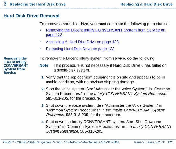
3 Replacing the Hard Disk Drive Replacing a Hard Disk Drive
Intuity™ CONVERSANT® System Version 7.0 MAP/40P Maintenance 585-313-108 Issue 2 January 2000 122
Hard Disk Drive Removal
To remove a hard disk drive, you must complete the following procedures:
• Removing the Lucent Intuity CONVERSANT System from Service on page 122
• Accessing A Hard Disk Drive on page 123
• Extracting Hard Disk Drive on page 123
Removing the Lucent Intuity CONVERSANT System from Service
To remove the Lucent Intuity system from service, do the following:
Note: This procedure is not necessary if Hard Disk Drive 0 has failed on a single-disk system.
1 Verify that the replacement equipment is on site and appears to be in usable condition, with no obvious shipping damage.
2 Stop the voice system. See “Administer the Voice System,” in “Common System Procedures,” in the Intuity CONVERSANT System Reference, 585-313-205, for the procedure.
3 Shut down the voice system. See “Administer the Voice System,” in “Common System Procedures,” in the Intuity CONVERSANT System Reference, 585-313-205, for the procedure.
4 Shut down the Intuity CONVERSANT system. See “Shut Down the System,” in “Common System Procedures,” in the Intuity CONVERSANT System Reference, 585-313-205.

3 Replacing the Hard Disk Drive Replacing a Hard Disk Drive
Intuity™ CONVERSANT® System Version 7.0 MAP/40P Maintenance 585-313-108 Issue 2 January 2000 123
5 Remove the incoming power. See Removing Power from the MAP/40P on page 6 in Chapter 1, Getting Inside the Computer .
Accessing A Hard Disk Drive
To access a hard disk drive, remove the dress cover. See Removing the Dress Cover on page 9 in Chapter 1, Getting Inside the Computer .
Extracting Hard Disk Drive
To extract a hard disk drive, do the following:
1 Remove the SCSI and power cables from the back of Hard Disk Drive 0 and 1 (if installed).
2 Loosen the two screws holding the hard disk drive bracket to the MAP/40P chassis.
3 Slide the hard disk drive bracket toward the floppy drive to release it from the keyed retainers then lift it from the MAP/40P.
4 Remove the screws which secure Hard Disk Drive 0 or 1 to the hard disk drive bracket.
Note: Hard Disk Drive 0 is nearest the fans.
5 Place the hard disk drive assembly, with the printed circuit board facing up, on an ESD-protected surface.
6 Continue with the procedure in Hard Disk Drive Installation on page 124.

3 Replacing the Hard Disk Drive Replacing a Hard Disk Drive
Intuity™ CONVERSANT® System Version 7.0 MAP/40P Maintenance 585-313-108 Issue 2 January 2000 124
Hard Disk Drive Installation
To install Hard Disk Drive 0, you must complete the following procedures:
• Installing the Hard Disk Drive Jumpers on page 124
• Inserting A Hard Disk Drive on page 125
Installing the Hard Disk Drive Jumpers
The Lucent Intuity system supports Quantum hard disk drive. Figure 47 on page 124 and Figure 48 on page 125 show the jumper settings for the hard disk drives.
Figure 47. Jumper Settings for SCSI ID 0

3 Replacing the Hard Disk Drive Replacing a Hard Disk Drive
Intuity™ CONVERSANT® System Version 7.0 MAP/40P Maintenance 585-313-108 Issue 2 January 2000 125
Figure 48. Jumper Settings for SCSI ID 1
Inserting A Hard Disk Drive
To insert the hard disk drive, do the following:
1 Remove the new hard disk drive from its ESD-protective wrapping.
Note: Keep the package and all ESD-protective wrapping to return the defective unit. Re-use of the original replacement unit packaging is necessary to meet the manufacturer’s warranty.
2 Align Hard Disk Drive 0 or 1, in the hard disk drive bracket, with the jumpers near the top of the bracket.
3 Secure the hard disk drive in the hard disk drive bracket using the screws removed in Step 4 of Extracting Hard Disk Drive on page 123.
4 Connect the SCSI and power cables to the back of Hard Disk Drive 0 and 1, if installed.
5 Secure the hard disk drive bracket to the chassis using the two screws loosened in Step 2 of Extracting Hard Disk Drive on page 123.

3 Replacing the Hard Disk Drive Replacing Hard Disk Drive 0
Intuity™ CONVERSANT® System Version 7.0 MAP/40P Maintenance 585-313-108 Issue 2 January 2000 126
6 Return to either the procedure Replacing Hard Disk Drive 0 (Nonmirrored or Single-Disk System) on page 126 or Replacing Hard Disk Drive 0 (Mirrored System) on page 128 to complete the system recovery.
Replacing Hard Disk Drive 0
The following procedure explains how to replace a hard disk drive on an existing Intuity CONVERSANT system.
The following sections list the procedures for replacing Hard Disk Drive 0 in mirrored, nonmirrored, and single-disk systems.
Replacing Hard Disk Drive 0 (Nonmirrored or Single-Disk System)
Because Hard Disk Drive 0 contains the base system software, you must reinstall the entire Intuity CONVERSANT system if this disk fails on a nonmirrored or single-disk system, after the hard disk drive has been replaced.
Replacing the Hard Disk Drive
To replace the hard disk drive, do the following:
1 Remove Hard Disk Drive 0 from the system. See Replacing a Hard Disk Drive on page 120 for the procedure.

3 Replacing the Hard Disk Drive Replacing Hard Disk Drive 0
Intuity™ CONVERSANT® System Version 7.0 MAP/40P Maintenance 585-313-108 Issue 2 January 2000 127
2 Set the jumpers on the replacement Hard Disk Drive 0. See Replacing a Hard Disk Drive on page 120 for the procedure.
3 Place the replacement Hard Disk Drive 0 in Bay 4. See Replacing a Hard Disk Drive on page 120 for the procedure.
Restoring the Intuity CONVERSANT System
! CAUTION:After installing a 2-Gbyte hard disk drive into a system as Disk 0, DO NOT ATTEMPT TO INSTALL AN OLDER VERSION OF UnixWare. The version of the operating system tape that should be used contains the phrase “Independent Image.” If the operating system tape does not contain this phrase, notify the remote maintenance center immediately.
To reinstall the Intuity CONVERSANT system software, do the following:
1 Restore the system using the CONVERSANT Image Tape created using the mkimage command. See “Restore the System,” in “Common System Procedures,” in the Intuity CONVERSANT System Reference, 585-313-205.
2 Restore the speech files using the spres command. See Appendix A, “Summary of Commands,” in Intuity CONVERSANT System Version 7.0 Administration, 585-313-501.

3 Replacing the Hard Disk Drive Replacing Hard Disk Drive 0
Intuity™ CONVERSANT® System Version 7.0 MAP/40P Maintenance 585-313-108 Issue 2 January 2000 128
Replacing Hard Disk Drive 0 (Mirrored System)
If Hard Disk Drive 0 fails in a mirrored system, the system will still be operational and there will be no noticeable degradation of service. The following procedure explains how to replace Hard Disk Drive 0 on a mirrored system.
! CAUTION:This initial synchronization of data on a mirrored system can degrade service, depending on system load. Therefore, perform this procedure only during off-peak hours.
Replacing the Hard Disk Drive
To replace the hard disk drive, do the following:
1 Remove Hard Disk Drive 0 from the system. See Replacing a Hard Disk Drive on page 120 for the procedure.
2 Set the jumpers on the replacement Hard Disk Drive 0. See Replacing a Hard Disk Drive on page 120 for the procedure.
3 Place the replacement Hard Disk Drive 0. See Replacing a Hard Disk Drive on page 120 for the procedure.
Restoring the Intuity CONVERSANT System
To restore the Intuity CONVERSANT system, do the following:
1 Log in as root.
2 Enter vxdiskadm
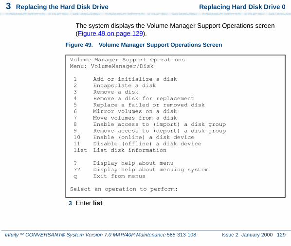
3 Replacing the Hard Disk Drive Replacing Hard Disk Drive 0
Intuity™ CONVERSANT® System Version 7.0 MAP/40P Maintenance 585-313-108 Issue 2 January 2000 129
The system displays the Volume Manager Support Operations screen (Figure 49 on page 129).
Figure 49. Volume Manager Support Operations Screen
3 Enter list
Volume Manager Support OperationsMenu: VolumeManager/Disk
1 Add or initialize a disk 2 Encapsulate a disk 3 Remove a disk 4 Remove a disk for replacement 5 Replace a failed or removed disk 6 Mirror volumes on a disk 7 Move volumes from a disk 8 Enable access to (import) a disk group 9 Remove access to (deport) a disk group 10 Enable (online) a disk device 11 Disable (offline) a disk device list List disk information
? Display help about menu ?? Display help about menuing system q Exit from menus
Select an operation to perform:

3 Replacing the Hard Disk Drive Replacing Hard Disk Drive 0
Intuity™ CONVERSANT® System Version 7.0 MAP/40P Maintenance 585-313-108 Issue 2 January 2000 130
The system displays the List Disk Information screen (Figure 50 on page 130).
Figure 50. List Disk Information Screen
4 Press ENTER.
The system displays the following message:
DEVICE DISK GROUP STATUSc0b0t0d0 disk00 rootdg onlinec0b0t1d0 disk01 rootdg online
List Disk InformationMenu: VolumeManager/Disk/ListDisk
Use this menu option to display a list of disks. You canalso choose to list detailed information about the disk ata specific disk device address.
Enter disk device or "all" [<address>,all,q,?] (default:all)

3 Replacing the Hard Disk Drive Replacing Hard Disk Drive 0
Intuity™ CONVERSANT® System Version 7.0 MAP/40P Maintenance 585-313-108 Issue 2 January 2000 131
5 Record the device IDs and disk names in the following table.
6 Press ENTER.
The system displays the Volume Manager Support Operations screen (Figure 49 on page 129).
7 Enter 4
The system displays the following message:
Enter the name of the disk to remove.
8 Enter the disk name for the drive with the device ID c0b0t0d0.
Note: This should be disk00.
The system displays the Volume Manager Support Operations screen (Figure 49 on page 129).
9 Enter 5
Device Disk

3 Replacing the Hard Disk Drive Replacing Hard Disk Drive 0
Intuity™ CONVERSANT® System Version 7.0 MAP/40P Maintenance 585-313-108 Issue 2 January 2000 132
The system displays the following message:
Enter the name of the disk to replace.
10 Enter the same disk name as in step 8.
The system displays the following message:
Enter the device ID of the disk to use as a replacement.
11 Enter c0b0t0d0
The system displays the Hard Disk Partitioning – Disk 0 screen (Figure 51 on page 133).

3 Replacing the Hard Disk Drive Replacing Hard Disk Drive 0
Intuity™ CONVERSANT® System Version 7.0 MAP/40P Maintenance 585-313-108 Issue 2 January 2000 133
Figure 51. Hard Disk Partitioning – Disk 0 Screen
12 Enter 1
The system responds with a screen where you must supply information for the new partition.
13 Select UNIX System. Use and to move through the Partition Type field selections.
14 Press TAB to move to the Percentage of Disk field.
Total disk size is 2048 cylinders (2048.0MB)
Partition Status Type Start End Length % ApproxMB
1 Active UNIX 0 2047 2048 100 248.0System
SELECT ONE OF THE FOLLOWING.
0. Overwrite system master boot code1. Create a partition2. Change Active (Boot from) partition3. Delete a partition4. Update (Update disk configuration and exit)5. Exit (Exit without updating disk configuration)
Enter selection:

3 Replacing the Hard Disk Drive Replacing Hard Disk Drive 1
Intuity™ CONVERSANT® System Version 7.0 MAP/40P Maintenance 585-313-108 Issue 2 January 2000 134
15 Enter 100
16 Press to move to the Apply box and press ENTER .
The system displays the Hard Disk Partitioning – Disk 0 screen (Figure 51 on page 133).
17 Enter 4
The system displays the Volume Manager Support Operations screen (Figure 49 on page 129).
18 Enter q
The system starts mirroring the contents of Hard Disk Drive 1 to Hard Disk Drive 0. This will not interrupt normal operation of the Intuity CONVERSANT system.
Replacing Hard Disk Drive 1
The following procedure explains how to replace a hard disk drive on an existing Intuity CONVERSANT system.
This procedure only applies to Hard Disk Drive 1. If it is not possible to log in to the Intuity CONVERSANT system, it is possible that Hard Disk Drive 0 has failed. See one of the procedures in Replacing Hard Disk Drive 0 on page 126 (nonmirrored or mirrored, depending on your configuration) for instructions.

3 Replacing the Hard Disk Drive Replacing Hard Disk Drive 1
Intuity™ CONVERSANT® System Version 7.0 MAP/40P Maintenance 585-313-108 Issue 2 January 2000 135
Software and Hardware Procedures for Replacing Hard Disk Drive 1(Nonmirrored System)
If Hard Disk Drive 1 fails in a nonmirrored system, the system is still operational. However, speech files are lost. The following procedure explains how to replace Hard Disk Drive 1 on a nonmirrored system.
Replacing the Hard Disk Drive
To replace Hard Disk Drive 1, do the following:
1 Remove Hard Disk Drive 1 from the system. See Replacing a Hard Disk Drive on page 120 for the procedure.
2 Set the jumpers on the replacement Hard Disk Drive 1. See Replacing a Hard Disk Drive on page 120 for the procedure.
3 Place the replacement Hard Disk Drive 1. See Replacing a Hard Disk Drive on page 120 for the procedure.
Restoring the Intuity CONVERSANT System
To restore the Intuity CONVERSANT system, do the following:
1 Log in as root.
2 Enter vxdiskadm
The system displays the Volume Manager Support Operations screen (Figure 49 on page 129).
3 Enter list
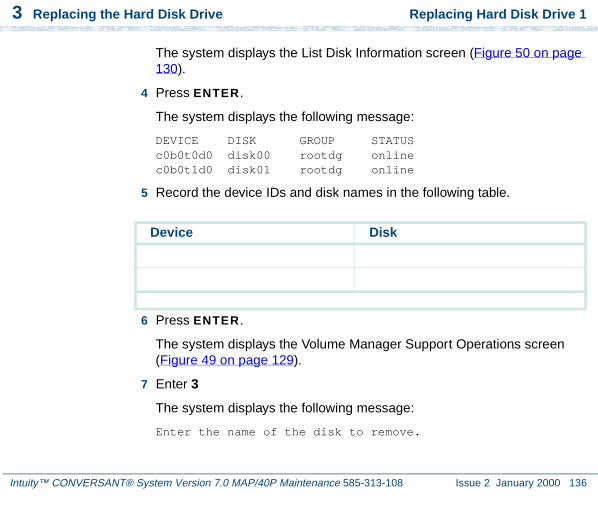
3 Replacing the Hard Disk Drive Replacing Hard Disk Drive 1
Intuity™ CONVERSANT® System Version 7.0 MAP/40P Maintenance 585-313-108 Issue 2 January 2000 136
The system displays the List Disk Information screen (Figure 50 on page 130).
4 Press ENTER.
The system displays the following message:
DEVICE DISK GROUP STATUSc0b0t0d0 disk00 rootdg onlinec0b0t1d0 disk01 rootdg online
5 Record the device IDs and disk names in the following table.
6 Press ENTER.
The system displays the Volume Manager Support Operations screen (Figure 49 on page 129).
7 Enter 3
The system displays the following message:
Enter the name of the disk to remove.
Device Disk

3 Replacing the Hard Disk Drive Replacing Hard Disk Drive 1
Intuity™ CONVERSANT® System Version 7.0 MAP/40P Maintenance 585-313-108 Issue 2 January 2000 137
8 Enter the disk name for the drive with the device ID c0b0t1d0.
Note: This should be disk01.
The system displays the Volume Manager Support Operations screen (Figure 49 on page 129).
9 Add Hard Disk Drive 1 to the system. See Adding a Hard Disk Drive to a System for Speech Storage on page 149.
10 Restore the speech files using the spres command. See Appendix A, “Summary of Commands” in Intuity CONVERSANT System Version 7.0 Administration, 585-313-501, for more information.
Software and Hardware Procedures for Replacing Hard Disk Drive 1(Mirrored System)
If Hard Disk Drive 1 fails in a mirrored system, the system is still operational and there is no noticeable degradation of service. The following procedure explains how to replace Hard Disk Drive 1 on a mirrored system.
! CAUTION:This initial synchronization of data on a mirrored system can degrade service, depending on system load. Therefore, perform this procedure only during off-peak hours.

3 Replacing the Hard Disk Drive Replacing Hard Disk Drive 1
Intuity™ CONVERSANT® System Version 7.0 MAP/40P Maintenance 585-313-108 Issue 2 January 2000 138
Replacing the Hard Disk Drive
To replace Hard Disk Drive 1, do the following:
1 Remove Hard Disk Drive 1 from the system. See Replacing a Hard Disk Drive on page 120 for the procedure.
2 Set the jumpers on the replacement Hard Disk Drive 1. See Replacing a Hard Disk Drive on page 120 for the procedure.
3 Place the replacement Hard Disk Drive 1 in Bay 3. See Replacing a Hard Disk Drive on page 120 for the procedure.
Restoring the Intuity CONVERSANT System
To restore the Intuity CONVERSANT system, do the following:
1 Log in as root.
2 Enter vxdiskadm
The system displays the Volume Manager Support Operations screen (Figure 49 on page 129).
3 Enter list
The system displays the List Disk Information screen (Figure 50 on page 130).
4 Press ENTER.
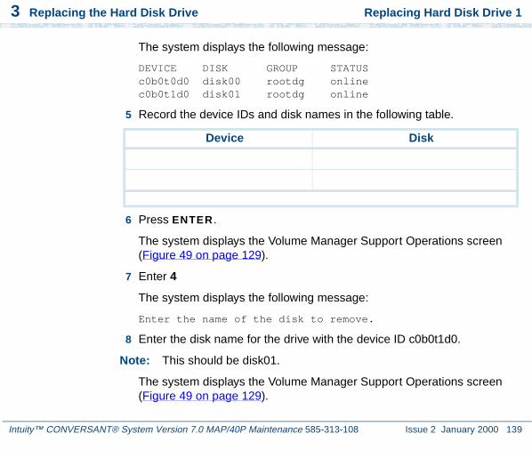
3 Replacing the Hard Disk Drive Replacing Hard Disk Drive 1
Intuity™ CONVERSANT® System Version 7.0 MAP/40P Maintenance 585-313-108 Issue 2 January 2000 139
The system displays the following message:
DEVICE DISK GROUP STATUSc0b0t0d0 disk00 rootdg onlinec0b0t1d0 disk01 rootdg online
5 Record the device IDs and disk names in the following table.
6 Press ENTER.
The system displays the Volume Manager Support Operations screen (Figure 49 on page 129).
7 Enter 4
The system displays the following message:
Enter the name of the disk to remove.
8 Enter the disk name for the drive with the device ID c0b0t1d0.
Note: This should be disk01.
The system displays the Volume Manager Support Operations screen (Figure 49 on page 129).
Device Disk

3 Replacing the Hard Disk Drive Replacing Hard Disk Drive 1
Intuity™ CONVERSANT® System Version 7.0 MAP/40P Maintenance 585-313-108 Issue 2 January 2000 140
9 Enter 5
The system displays the following message:
Enter the name of the disk to replace.
10 Enter the same disk name as in Step 8.
The system displays the following message:
Enter the device ID of the disk to use as a replacement.
11 Enter c0b0t1d0
The system displays the Hard Disk Partitioning – Disk 1 screen (Figure 52 on page 141).

3 Replacing the Hard Disk Drive Replacing Hard Disk Drive 1
Intuity™ CONVERSANT® System Version 7.0 MAP/40P Maintenance 585-313-108 Issue 2 January 2000 141
Figure 52. Hard Disk Partitioning – Disk 1 Screen
12 Enter 1
The system responds with a screen where you must supply information for the new partition.
13 Select UNIX System. Use and to move through the Partition Type field selections.
14 Press TAB to move to the Percentage of Disk field.
Total disk size is 2048 cylinders (2048.0MB)
Partition Status Type Start End Length % ApproxMB
1 Active UNIX 0 2047 2048 100 2048.0System
SELECT ONE OF THE FOLLOWING
0. Overwrite system master boot code1. Create a partition2. Change Active (Boot from) partition3. Delete a partition4. Update (Update disk configuration and exit)5. Exit (Exit without updating disk configuration)
Enter selection:

3 Replacing the Hard Disk Drive Adding a Hard Disk Drive
Intuity™ CONVERSANT® System Version 7.0 MAP/40P Maintenance 585-313-108 Issue 2 January 2000 142
15 Enter 100
16 Press to move to the Apply box and press ENTER .
The system displays the Hard Disk Partitioning – Disk 1 screen (Figure 52 on page 141).
17 Enter 4
The system displays the Volume Manager Support Operations screen (Figure 49 on page 129).
18 Enter q
The system starts mirroring the contents of Hard Disk Drive 0 to Hard Disk Drive 1. This does not interrupt normal operation of the Intuity CONVERSANT system.
Adding a Hard Disk Drive
This section details the procedures for adding a second hard disk drive to an Intuity CONVERSANT system with only one hard disk drive. If you are replacing an existing drive, see Replacing Hard Disk Drive 0 on page 126 or Replacing Hard Disk Drive 1 on page 134.

3 Replacing the Hard Disk Drive Adding a Hard Disk Drive
Intuity™ CONVERSANT® System Version 7.0 MAP/40P Maintenance 585-313-108 Issue 2 January 2000 143
Adding a Hard Disk Drive to a System for Mirroring
To add a hard disk drive, do the following:
1 Install the new hard disk drive. See Replacing a Hard Disk Drive on page 120.
2 Clean the new hard disk drive. See Cleaning a Hard Disk Drive on page 153.
3 Log in as root.
4 Enter fdisk /dev/rdsk/c0b0txd0s0
The system displays the following message:
The recommended default partitioning for your disk is 100% UNIX system partition.
To select this, please type "y". To partition your disk differently, type "n" and the "fdisk" program will let you select other partitions.
5 Enter y
6 Enter vxdiskadm
The system displays the Volume Manager Support Operations screen (Figure 49 on page 129).
7 Enter 1

3 Replacing the Hard Disk Drive Adding a Hard Disk Drive
Intuity™ CONVERSANT® System Version 7.0 MAP/40P Maintenance 585-313-108 Issue 2 January 2000 144
The system displays the Add or Initialize a Disk screen (Figure 53 on page 144).
Figure 53. Add or Initialize a Disk Screen
8 Enter list to show a list of the disk devices recognized by the system.
Add or initialize a diskMenu: VolumeManager/Disk/AddDisk
Use this operation to add a disk to a disk group. You can select an existing disk group or create a new disk group. You can also initialize a disk without adding it to a disk group, which leaves the disk available for use as a replacement disk. This operation takes, as input, a disk device, for example c0b0t2d0, a disk group (or none to leave the disk available for as a replacement disk). If you are adding the disk to a disk group, you will be asked to give a name to the disk.
More than one disk or pattern may be entered at the prompt. Here are some disk selection examples:
all: all disksc3 c4b0t2: all disks on both controller 3 and controller 4, bus 0,
target 2c3b0t4d2: a single disk
Select disk device to add [<pattern-list>,all,list,q,?]

3 Replacing the Hard Disk Drive Adding a Hard Disk Drive
Intuity™ CONVERSANT® System Version 7.0 MAP/40P Maintenance 585-313-108 Issue 2 January 2000 145
Note: The list command will show the newly added disk online or error, but not as part of any disk group. Choose this disk address for the next prompt.
The system displays a message similar to the following message:
DEVICE DISK GROUP STATUSc0b0t0d0 disk00 rootdg onlinec0b0t1d0 - - online
9 Enter the device to add, in the form c0b0tXd0, where X is the number of the drive that you are adding.
The system displays the following message:
Here is the disk selected. Output format: [Device_Name]
c0b0tXd0
Continue operation? [y,n,q,?] (default: y)
10 Enter y
The system displays the following message:
Disk device c0b0tXd0 appears to have been initialized already.The disk is currently available as a replacement disk.

3 Replacing the Hard Disk Drive Adding a Hard Disk Drive
Intuity™ CONVERSANT® System Version 7.0 MAP/40P Maintenance 585-313-108 Issue 2 January 2000 146
Note: If the disk is a brand new disk, the above message is not displayed. Sometimes the newly added disk STATUS is shown as error instead of online. This may happen until the disk is added to the Volume Manager internal configuration files using vxdiskadm.
Do you wish to reinitialize c0b0tXd0?
11 Enter y
The system displays the following message:
You can choose to add this disk to an existing disk group, to create a new disk group, or you can choose to leave the disk available for use by future add or replacement operations. To create a new disk group, select a disk group name that does not yet exist. To leave the disk available for future use, specify a disk group name of "none".
Which disk group [<group>,none,list,q,?] (default: rootdg)
12 Press ENTER.
The system displays the following message:
Use a default disk name for the disk? [y,n.q,?] (default: y)
13 Enter n

3 Replacing the Hard Disk Drive Adding a Hard Disk Drive
Intuity™ CONVERSANT® System Version 7.0 MAP/40P Maintenance 585-313-108 Issue 2 January 2000 147
The system displays the following message:
Add disk as a hot-spare disk for? [y,n,q,?](default: n)
14 Enter n
The system displays the following message:
The selected disks will be added to the disk group rootdg with the disk name that you will specify interactively
c0b0tXd0
Continue the operation? [y,n,q,?] (default: y)
15 Enter y
The system displays the following message:
The following disk device appears to have been initialized already. The disk is currently available as a replacement disk.Output format: [Device_name]
c0b0tXd0
Use this device? [y,n,q,?] (default: y)
Note: If the disk is a brand new disk, the above message is not displayed.
16 Enter y

3 Replacing the Hard Disk Drive Adding a Hard Disk Drive
Intuity™ CONVERSANT® System Version 7.0 MAP/40P Maintenance 585-313-108 Issue 2 January 2000 148
The system displays the following message
The following disk you selected for use appears to have already been initialized for the Volume Manager. If you are certain the disk has already been initialized for the Volume Manager, then you do not need to reinitialize the disk deviceOutput format: [Device_Name]
c0b0tXd0
Reinitialize this device? [y,n,q,?] (default: y)
Note: If the disk is a brand new disk, the above message is not displayed.
17 Enter n
The system displays the following message:
Perform surface analysis (highly recommended). [y,n,q,?] default:y
18 Enter y
The system displays the following message:
Enter disk name for <c0d0tXd0> [<name>,q,?] (default: disk01)
19 Enter the disk name, or press ENTER to select disk01.

3 Replacing the Hard Disk Drive Adding a Hard Disk Drive
Intuity™ CONVERSANT® System Version 7.0 MAP/40P Maintenance 585-313-108 Issue 2 January 2000 149
The system displays the following message:
Adding disk device c0b0tXd0 to disk group rootdg with disk name <diskname>
Add or initialize other disks? [y,n,q,?] (default: n)
20 Press ENTER.
The system displays the Volume Support Manager Operations screen (Figure 49 on page 129).
21 Select q to quit
22 Enter vxdisk list
The system displays a message similar to the following message:
DEVICE DISK GROUP STATUSc0b0t0d0 disk00 rootdg onlinec0b0t1d0 - - online
23 Verify that the STATUS column for the disk is online.
Adding a Hard Disk Drive to a System for Speech Storage
Note: If you are using an existing disk, perform the Cleaning a Hard Disk Drive on page 153 procedure first.

3 Replacing the Hard Disk Drive Adding a Hard Disk Drive
Intuity™ CONVERSANT® System Version 7.0 MAP/40P Maintenance 585-313-108 Issue 2 January 2000 150
1 Complete the procedure in Adding a Hard Disk Drive to a System for Mirroring on page 143.
2 Log in to the system as root.
3 Enter /mtce/bin/dispdisk
The system displays a message similar to the following:
Choose a disk from the following list
disk00 disk01
Enter disk:
4 Enter disk01
The system displays a message similar to the following:
Disk Name: disk01 Status: onlineDevice Name: c0b0t1d0s0 Length: 4187648Volumes on disk disk01:-------------------------homehome2rootvolstandvolswapvolusr

3 Replacing the Hard Disk Drive Adding a Hard Disk Drive
Intuity™ CONVERSANT® System Version 7.0 MAP/40P Maintenance 585-313-108 Issue 2 January 2000 151
5 Record the value shown in the Length field on the line below.
Length: __________________________
6 Enter /mtce/bin/makevol
The system displays the following message:
Enter Volume Name:
7 Enter home3
The system displays the following message:
Enter Volume Length:
8 Enter the number you recorded in Step 5.
The system displays the following message:
Number of mirrors set to: 0Volume layout set to: nocontigLogging type set to: NONEDisk Group set to: rootdg
Choose a disk from the following list:
disk00 disk01
Enter disk:
9 Enter the disk name (for example, disk01).

3 Replacing the Hard Disk Drive Adding a Hard Disk Drive
Intuity™ CONVERSANT® System Version 7.0 MAP/40P Maintenance 585-313-108 Issue 2 January 2000 152
The system displays the following message:
Please wait, this will take a couple of minutes.
Mkfs: make vxfs file system?
(DEL if wrong)
When the system prompt returns, an entry is automatically added /etc/vfstab for the home3 volume, and the file system is mounted.
Moving the Speech to the Speech Disk
Note: Direct calls away from the system during this procedure.
To add a speech disk to an existing system, do the following:
1 Log in as root.
2 Enter cd /home2/vfs/talkfiles
3 Enter find . -name -pring | cpio -pdmuv /home3/vfs/talkfiles
4 Enter vi /vs/data/irAPI.rc
5 Change the line SPEECHDIR=/home2/vfs/talkfiles to SPEECHDIR=/home3/vfs/talkfiles
6 Enter stop_vs

3 Replacing the Hard Disk Drive Cleaning a Hard Disk Drive
Intuity™ CONVERSANT® System Version 7.0 MAP/40P Maintenance 585-313-108 Issue 2 January 2000 153
7 Enter start_vs
8 Enter cd /home2/vfs/talkfiles
9 Enter rm -rf - *
The /home2 directory is now available for customer files.
Cleaning a Hard Disk Drive
Cleaning a hard disk drive can be done by:
• Using the fdisk command
• Low-level formatting the hard disk drive
Using the fdisk Command
A hard disk drive which contains data cannot be installed in a Intuity CONVERSANT system. The hard disk drive must be cleaned before use.
To clean a hard disk drive, do the following:
1 Log in to the system as root.
2 Enter fdisk /dev/rdsk/c0b0t1d0s0

3 Replacing the Hard Disk Drive Cleaning a Hard Disk Drive
Intuity™ CONVERSANT® System Version 7.0 MAP/40P Maintenance 585-313-108 Issue 2 January 2000 154
! CAUTION:The phrase c0b0t1d0s0 is the name of the disk to be cleaned. The phrase c0b0t1d0s0 is correct for Hard Disk Drive 1. Hard Disk Drive 0 is named c0b0t0d0s0.
The system displays the Disk Cleaning screen (Figure 54 on page 154).
Figure 54. Disk Cleaning Screen
3 Enter 3
Total disk size is 2048 cylinders (2048.0MB)
Partition Status Type Start End Length % ApproxMB
1 Active UNIX 0 2047 2048 100 2048.0System
SELECT ONE OF THE FOLLOWING
0. Overwrite system master boot code1. Create a partition2. Change Active (Boot from) partition3. Delete a partition4. Update (Update disk configuration and exit)5. Exit (Exit without updating disk configuration)
Enter selection:

3 Replacing the Hard Disk Drive Cleaning a Hard Disk Drive
Intuity™ CONVERSANT® System Version 7.0 MAP/40P Maintenance 585-313-108 Issue 2 January 2000 155
The system displays the following message:
Enter the number of the partition you want to delete (or enter x to exit)
4 Enter the number of the partition.
For the example given in Figure 54 on page 154, you would enter 1.
The system displays the following message:
Do you want to delete partition X? This will erase all files and programs in this partition (type "y" or "n").
5 Enter y
The system displays the following message:
Partition X has been deleted.
The system displays the Disk Cleaning screen (Figure 54 on page 154).
6 Enter 4
The system displays the following message:
If you have created or altered a partition, you must initialize the partition to reflect the new configuration. For a UNIX System partition run the disksetup(1m) command. For a DOS partition, run the DOS format command. Changes limited to the "Active’ status field require no additional action.

3 Replacing the Hard Disk Drive Cleaning a Hard Disk Drive
Intuity™ CONVERSANT® System Version 7.0 MAP/40P Maintenance 585-313-108 Issue 2 January 2000 156
7 Reboot the system. See “Reboot the System,” in “Common System Procedures,” in the Intuity CONVERSANT System Reference, 585-313-205.
Low-Level Formatting the Hard Disk Drive
The procedure for low-level formatting a hard disk drive differs depending on the CPU type installed on your system.
Low-Level Formatting with a P5 200 MHz CPU Circuit Card
To low-level format a hard disk drive, do the following:
1 Reboot the system. See “Reboot the System,” in “Common System Procedures,” in the Intuity CONVERSANT System Reference, 585-313-205.
2 Press CONTROL + A when prompted.
The system displays the Host Adapter Configuration screen (Figure 55 on page 157).
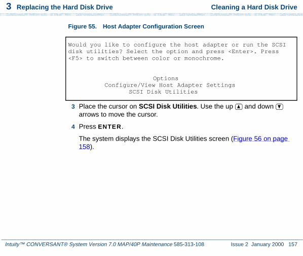
3 Replacing the Hard Disk Drive Cleaning a Hard Disk Drive
Intuity™ CONVERSANT® System Version 7.0 MAP/40P Maintenance 585-313-108 Issue 2 January 2000 157
Figure 55. Host Adapter Configuration Screen
3 Place the cursor on SCSI Disk Utilities. Use the up and down arrows to move the cursor.
4 Press ENTER.
The system displays the SCSI Disk Utilities screen (Figure 56 on page 158).
Would you like to configure the host adapter or run the SCSI disk utilities? Select the option and press <Enter>. Press <F5> to switch between color or monochrome.
OptionsConfigure/View Host Adapter Settings
SCSI Disk Utilities

3 Replacing the Hard Disk Drive Cleaning a Hard Disk Drive
Intuity™ CONVERSANT® System Version 7.0 MAP/40P Maintenance 585-313-108 Issue 2 January 2000 158
Figure 56. SCSI Disk Utilities Screen
5 Place the cursor on the SCSI Disk to be formatted. Use the up and down arrows to move the cursor.
6 Press ENTER.
The system displays the Configure/Format Disk screen (Figure 57 on page 158).
Figure 57. Configure/Format Disk Screen
Select SCSI Disk and press <Enter>.
SCSI ID #0 IBM DORS-32160SCSI ID #1 IBM DORS-32160SCSI ID #2 No DeviceSCSI ID #3 TANDBERG TDC4200SCSI ID #4 No DeviceSCSI ID #5 No DeviceSCSI ID #6 No DeviceSCSI ID #7 AIC - 7850
Configure Disk Format Disk
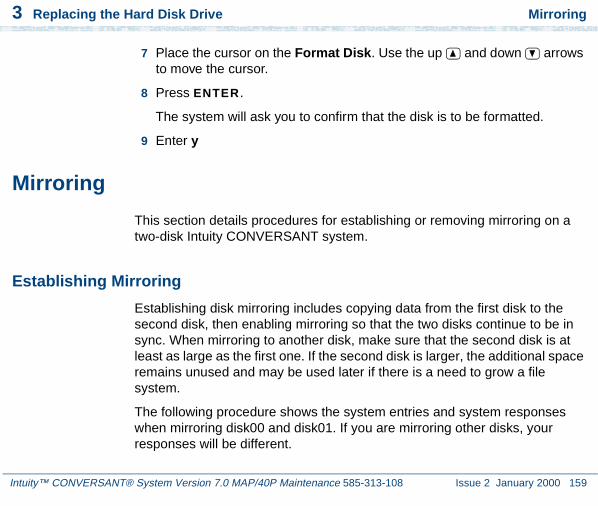
3 Replacing the Hard Disk Drive Mirroring
Intuity™ CONVERSANT® System Version 7.0 MAP/40P Maintenance 585-313-108 Issue 2 January 2000 159
7 Place the cursor on the Format Disk. Use the up and down arrows to move the cursor.
8 Press ENTER.
The system will ask you to confirm that the disk is to be formatted.
9 Enter y
Mirroring
This section details procedures for establishing or removing mirroring on a two-disk Intuity CONVERSANT system.
Establishing Mirroring
Establishing disk mirroring includes copying data from the first disk to the second disk, then enabling mirroring so that the two disks continue to be in sync. When mirroring to another disk, make sure that the second disk is at least as large as the first one. If the second disk is larger, the additional space remains unused and may be used later if there is a need to grow a file system.
The following procedure shows the system entries and system responses when mirroring disk00 and disk01. If you are mirroring other disks, your responses will be different.

3 Replacing the Hard Disk Drive Mirroring
Intuity™ CONVERSANT® System Version 7.0 MAP/40P Maintenance 585-313-108 Issue 2 January 2000 160
1 Set the jumpers on Hard Disk Drive 1. See Replacing a Hard Disk Drive on page 120 for the procedure.
2 Place Hard Disk Drive 1 in Bay 3. See Replacing a Hard Disk Drive on page 120.
3 Add Hard Disk Drive 1 to the system. See Adding a Hard Disk Drive to a System for Mirroring on page 143.
4 At the UNIX prompt, enter vxdiskadm
The system displays the Volume Manager Support Operations screen (Figure 49 on page 129).
5 Enter 6
The system displays the Mirror Volumes on a Disk screen (Figure 58 on page 161).

3 Replacing the Hard Disk Drive Mirroring
Intuity™ CONVERSANT® System Version 7.0 MAP/40P Maintenance 585-313-108 Issue 2 January 2000 161
Figure 58. Mirror Volumes on a Disk Screen
6 Enter list
The system displays the Disk Group screen (Figure 59 on page 162).
Mirror volumes on a diskMenu: VolumeManager/Disk/Mirror
This operation can be used to mirror volumes on a disk. These volumes can be mirrored onto another disk or onto any available disk space. Volumes will not be mirrored if they are already mirrored. Also, volumes that are comprised of more than one subdisk will not be mirrored.Mirroring volumes from the boot disk will produce a disk that can be used as an alternate boot disk.At the prompt below, supply the name of the disk containing the volumes to be mirrored.
Enter disk name

3 Replacing the Hard Disk Drive Mirroring
Intuity™ CONVERSANT® System Version 7.0 MAP/40P Maintenance 585-313-108 Issue 2 January 2000 162
Figure 59. Disk Group Screen
7 Enter disk00
The system displays the following message:
You can choose to mirror volumes from disk disk00 onto any available disk space, or you can choose to mirror onto a specific disk. To mirror to a specific disk, select the name of that disk. To mirror to any available disk space, select "any".
Enter destination disk [<disk>,list,q,?] (default: any)
8 Enter disk01
The system displays the following message:
The requested operation is to mirror all volumes on disk disk00 in disk group rootdg onto available disk space on disk disk01.
Disk group: rootdg
DM NAME DEVICE TYPE PRIVLEN PUBLEN PUBPATHdm disk00 c0b0t0d0s0 sliced 512 2422237 /dev/rdsk/c0b0t0d0sedm disk00 c0b0t1d0s0 sliced 512 3448320 /dev/rdsk/c0b0t1d0se
Enter disk name

3 Replacing the Hard Disk Drive Mirroring
Intuity™ CONVERSANT® System Version 7.0 MAP/40P Maintenance 585-313-108 Issue 2 January 2000 163
NOTE: This operation takes a long time to complete.
Continue with the operation?
9 Enter y
The system displays the following message:
Mirror volume standvolMirror volume swapvolMirror volume rootvolMirror volume disk006volMirror volume home3Mirror volume mtceMirror volume oracleMirror volume tmpMirror volume voice1Mirror volume voxemMirror volume vs
Mirroring of disk disk01 is complete.
Mirror volumes on another disk? [y,n,q,?] (default:n)
10 Enter n
The system displays the Volume Manager Support Operations screen (Figure 49 on page 129).
11 Enter q

3 Replacing the Hard Disk Drive Mirroring
Intuity™ CONVERSANT® System Version 7.0 MAP/40P Maintenance 585-313-108 Issue 2 January 2000 164
Removing Mirroring
To remove mirroring, do the following:
1 At the UNIX prompt, enter /mtce/bin/rmvolmirr
2 The system displays the following message:
Choose a VolumeName from the following list:
ALL standvol swapvol rootvol mtce oracle tmp vs
Enter VolumeName or ALL:
3 Enter ALL
The system displays the following message for each volume:
Mirroring for xxx volume has been turned off.
Volume mirror xxx has been removed.
where xxx is the volume name.

3 Replacing the Hard Disk Drive Disk Reuse
Intuity™ CONVERSANT® System Version 7.0 MAP/40P Maintenance 585-313-108 Issue 2 January 2000 165
Disk Reuse
Reusing for Mirroring
To reuse an existing speech disk for mirroring, do the following:
1 Log in as root.
Note: In the following steps, home3 is the volume where the speech files are stored.
2 Enter umount /home3
3 Enter voledit -rf rm home3
4 Establish mirroring. See Establishing Mirroring on page 159, and begin with step 4.
Reusing for Speech
To reuse an existing mirrored disk for speech, do the following:
1 Log in as root.
2 Remove mirroring. See Removing Mirroring on page 164.

3 Replacing the Hard Disk Drive Disk Reuse
Intuity™ CONVERSANT® System Version 7.0 MAP/40P Maintenance 585-313-108 Issue 2 January 2000 166
3 Add a disk for speech storage. See Adding a Hard Disk Drive to a System for Speech Storage on page 149, and begin with step 3.
4 Move the speech to the speech disk. See Moving the Speech to the Speech Disk on page 152.
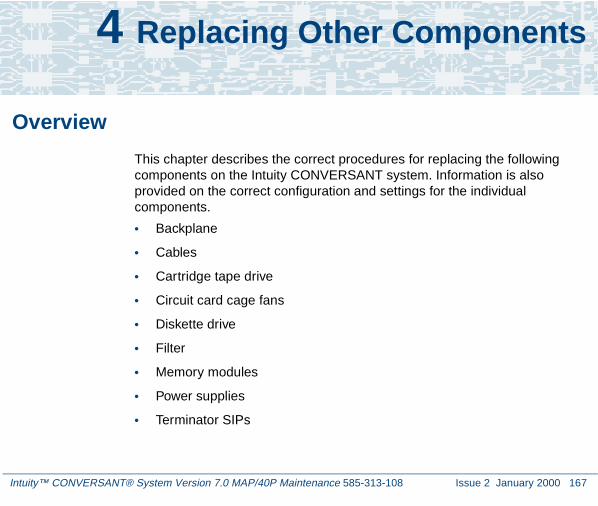
Intuity™ CONVERSANT® System Version 7.0 MAP/40P Maintenance 585-313-108 Issue 2 January 2000 167
4 Replacing Other Components
Overview
This chapter describes the correct procedures for replacing the following components on the Intuity CONVERSANT system. Information is also provided on the correct configuration and settings for the individual components.
• Backplane
• Cables
• Cartridge tape drive
• Circuit card cage fans
• Diskette drive
• Filter
• Memory modules
• Power supplies
• Terminator SIPs

4 Replacing Other Components Replacing the Electromagnetic Interference Reduction Components
Intuity™ CONVERSANT® System Version 7.0 MAP/40P Maintenance 585-313-108 Issue 2 January 2000 168
Note: For circuit card replacement procedures, see Chapter 2, Installing or Replacing Circuit Cards . For hard disk drive replacement procedures see Chapter 3, Replacing the Hard Disk Drive .
Replacing the Electromagnetic Interference Reduction Components
Before connecting peripherals or external devices, install toroids and/or ferrites to each interface cable. All installations require the installation of toroids and ferrites as described in the following procedures to meet the individual country agency electromagnetic compatibility (EMC) regulations.
A toroid (Type A), used only on a MAP/40P system, is a 2.5 inch (6.4 cm) circular ferrite. Toroids are made of a highly conductive carbon type of material that is very brittle. If a toroid ring fractures, it should immediately be replaced.
A ferrite (Type B) is a 1 inch (2.5 cm) rectangular device. Ferrites are made of a variable conductive carbon type material to reduce special EMI (electromagnetic interference) frequency band width. Available in split and solid ferrite forms, a special snap-back protective cover is used to install and keep the halves together.
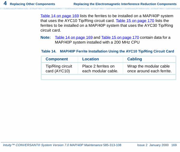
4 Replacing Other Components Replacing the Electromagnetic Interference Reduction Components
Intuity™ CONVERSANT® System Version 7.0 MAP/40P Maintenance 585-313-108 Issue 2 January 2000 169
Table 14 on page 169 lists the ferrites to be installed on a MAP/40P system that uses the AYC10 Tip/Ring circuit card. Table 15 on page 170 lists the ferrites to be installed on a MAP/40P system that uses the AYC30 Tip/Ring circuit card.
Note: Table 14 on page 169 and Table 15 on page 170 contain data for a MAP/40P system installed with a 200 MHz CPU
Table 14. MAP/40P Ferrite Installation Using the AYC10 Tip/Ring Circuit Card
Component Location Cabling
Tip/Ring circuit card (AYC10)
Place 2 ferrites on each modular cable.
Wrap the modular cable once around each ferrite.

4 Replacing Other Components Replacing the Electromagnetic Interference Reduction Components
Intuity™ CONVERSANT® System Version 7.0 MAP/40P Maintenance 585-313-108 Issue 2 January 2000 170
General Toroid and Ferrite Installation Guidelines
! CAUTION:Handle toroids and ferrites with care. Toroids and ferrites are easily fractured or broken. Immediately replace any fractured or broken toroids or ferrites as they are no longer effective for EMC control.
When installing toroids or ferrites:
• Install toroids or ferrites to cables as required.
• Minimize the amount of cable between the toroids or ferrites and the computer chassis.
Table 15. MAP/40P Ferrite Installation Using the AYC30 Tip/Ring Circuit Card
Component Location Cabling
Tip/Ring circuit card (AYC30)
Place 2 ferrites on each modular cable.
• Wrap the modular cable once around each ferrite.
• Wrap each modular cable twice through the toroid.
See Installing a Toroid on the MAP/40P on page 175 for general toroid installation.

4 Replacing Other Components Replacing the Electromagnetic Interference Reduction Components
Intuity™ CONVERSANT® System Version 7.0 MAP/40P Maintenance 585-313-108 Issue 2 January 2000 171
• Wrap cables as tightly as possible. Do not leave large amounts of slack in the loop(s).
• Use cable ties, when required, behind the ferrites to keep the ferrites in place.
Installing a Ferrite
To install a ferrite, do the following:
1 Open the ferrite by gently pulling the fastener away from the body of the ferrite.
2 Place the cord or cable in the groove inside the ferrite (Figure 60 on page 172).
Note: Maintain minimum cable lead length between the ferrite and the computer chassis.

4 Replacing Other Components Replacing the Electromagnetic Interference Reduction Components
Intuity™ CONVERSANT® System Version 7.0 MAP/40P Maintenance 585-313-108 Issue 2 January 2000 172
Figure 60. Example Ferrite (Type B) Installation
incvfer1 LJK 032598
2
3
4
1
4
1. Ferrite in open position
2. Ferrite in snapped closed position
3. Cable tie
4. To the computer

4 Replacing Other Components Replacing the Electromagnetic Interference Reduction Components
Intuity™ CONVERSANT® System Version 7.0 MAP/40P Maintenance 585-313-108 Issue 2 January 2000 173
If the cable is to be wrapped around the ferrite, wrap the cable tightly around half of the ferrite and place the cable into the groove (Figure 61 on page 173).
If the cable is to be wrapped around two ferrites, ensure the second ferrite is close to the first ferrite assembly (Figure 62 on page 174).
Figure 61. Example of Cable Wrapped Around Ferrite
incvrfer2 LJK 032698
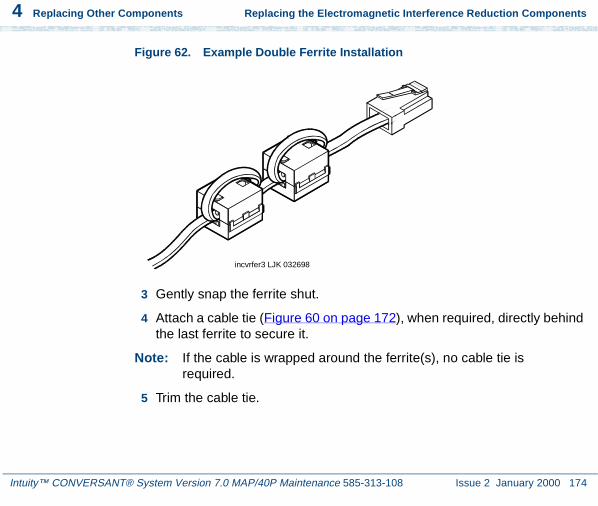
4 Replacing Other Components Replacing the Electromagnetic Interference Reduction Components
Intuity™ CONVERSANT® System Version 7.0 MAP/40P Maintenance 585-313-108 Issue 2 January 2000 174
Figure 62. Example Double Ferrite Installation
3 Gently snap the ferrite shut.
4 Attach a cable tie (Figure 60 on page 172), when required, directly behind the last ferrite to secure it.
Note: If the cable is wrapped around the ferrite(s), no cable tie is required.
5 Trim the cable tie.
incvrfer3 LJK 032698

4 Replacing Other Components Replacing the Electromagnetic Interference Reduction Components
Intuity™ CONVERSANT® System Version 7.0 MAP/40P Maintenance 585-313-108 Issue 2 January 2000 175
Installing a Toroid on the MAP/40P
The following is the general toroid installation procedure to be used on a MAP/40P system. Figure 63 on page 176 shows an example of a paired toroid installation.
To install a toroid, do the following:
1 Place the toroid close to the computer chassis.
2 Wrap each modular cable tightly around the toroid.
3 Secure the cable(s) with a small cable tie to reduce cable movement.
4 Trim off any excess from the cable tie.
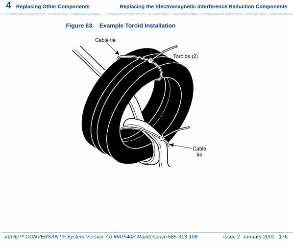
4 Replacing Other Components Replacing the Electromagnetic Interference Reduction Components
Intuity™ CONVERSANT® System Version 7.0 MAP/40P Maintenance 585-313-108 Issue 2 January 2000 176
Figure 63. Example Toroid Installation

4 Replacing Other Components Replacing the Backplane
Intuity™ CONVERSANT® System Version 7.0 MAP/40P Maintenance 585-313-108 Issue 2 January 2000 177
Replacing the Backplane
The following procedures detail removing and installing the backplane. The backplane (Figure 64 on page 178) is located in the MAP/40P card cage area as shown in Figure 65 on page 179.

4 Replacing Other Components Replacing the Backplane
Intuity™ CONVERSANT® System Version 7.0 MAP/40P Maintenance 585-313-108 Issue 2 January 2000 178
Figure 64. MAP/40P Backplane
bpmxm40a KLC 082597
1
2
3
J18
RE
AR
KB
DJ1
9F
RO
NT
KB
DJ2
1C
PU
INT
ER
FAC
EF
RO
NT
PA
NE
L
J20
1 2
4 1. Attach power cable here. Align from top with wires: red red red white black black
2. Attach power cable here. Align from top with wires: black black blue yellow red orange
3. Attach power cable here. Align from top with wires: red red red black black
4. Voltage measurement points

4 Replacing Other Components Replacing the Backplane
Intuity™ CONVERSANT® System Version 7.0 MAP/40P Maintenance 585-313-108 Issue 2 January 2000 179
Figure 65. MAP/40P Internal Layout
J18
RE
AR
KB
DJ1
9F
RO
NT
KB
DJ
21C
PU
INT
ER
FAC
EF
RO
NT
PAN
EL
J20
1 2
mpmxtopv KLC 082197
1
2
6
7
8
6
4
5
3
1. Power supply
2. Backplane
3. Peripheral Bay1 - unused
4. Peripheral Bay 2 - cartridge tape drive
5. Peripheral Bay 3 - diskette drive
6. Circuit card cage fan
7. Peripheral Bay 4 - Hard Disk Drive 0
8. Peripheral Bay 5 - Hard Disk Drive 1

4 Replacing Other Components Replacing the Backplane
Intuity™ CONVERSANT® System Version 7.0 MAP/40P Maintenance 585-313-108 Issue 2 January 2000 180
Removing the Backplane
! CAUTION:Observe proper electrostatic discharge precautions when you handle computer components. Wear an antistatic wrist strap that touches your bare skin and connect the strap cable to an earth ground. See Protecting Against Damage from Electrostatic Discharge on page 2, in Chapter 1, Getting Inside the Computer .
To remove the backplane, do the following:
1 Verify that the replacement equipment is on site and appears to be in usable condition, with no obvious shipping damage.
2 If the system is in service, perform the following Steps a and b.
a Stop the voice system. See “Administer the Voice System,” in “Common System Procedures,” in the Intuity CONVERSANT System Reference, 585-313-205, for the procedure.
b Shut down the voice system. See “Administer the Voice System,” in “Common System Procedures,” in the Intuity CONVERSANT System Reference, 585-313-205, for the procedure.
c Shut down the Intuity CONVERSANT system. See “Shut Down the System,” in “Common System Procedures,” in the Intuity CONVERSANT System Reference, 585-313-205.
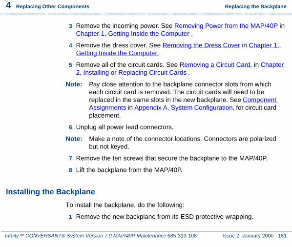
4 Replacing Other Components Replacing the Backplane
Intuity™ CONVERSANT® System Version 7.0 MAP/40P Maintenance 585-313-108 Issue 2 January 2000 181
3 Remove the incoming power. See Removing Power from the MAP/40P in Chapter 1, Getting Inside the Computer .
4 Remove the dress cover. See Removing the Dress Cover in Chapter 1, Getting Inside the Computer .
5 Remove all of the circuit cards. See Removing a Circuit Card, in Chapter 2, Installing or Replacing Circuit Cards .
Note: Pay close attention to the backplane connector slots from which each circuit card is removed. The circuit cards will need to be replaced in the same slots in the new backplane. See Component Assignments in Appendix A, System Configuration, for circuit card placement.
6 Unplug all power lead connectors.
Note: Make a note of the connector locations. Connectors are polarized but not keyed.
7 Remove the ten screws that secure the backplane to the MAP/40P.
8 Lift the backplane from the MAP/40P.
Installing the Backplane
To install the backplane, do the following:
1 Remove the new backplane from its ESD protective wrapping.

4 Replacing Other Components Replacing the Backplane
Intuity™ CONVERSANT® System Version 7.0 MAP/40P Maintenance 585-313-108 Issue 2 January 2000 182
Note: Keep the package and all ESD-protective wrapping to return the defective unit. Re-use of the original replacement unit packaging is necessary to meet the manufacturer’s warranty.
2 Mount the new backplane to the MAP/40P chassis using the ten screws you removed in step 7 of the procedure in Removing the Backplane on page 180.
Note: Make sure no wiring is trapped between standoffs and backplane. Redress the COM2 cable to a position near and under the CPU.
3 Connect all power cables that you removed in step 6 of the procedure in Removing the Backplane on page 180.
4 Seat the CPU circuit card and the video controller card. See Installing a Circuit Card on page 14, in Chapter 2, Installing or Replacing Circuit Cards .
Note: Be sure to mount these cards in their correct backplane slot. See Component Assignments on page 466 in Appendix A, System Configuration, for these locations.
5 With the MAP/40P still disassembled, connect the COM2 interface and keyboard to the appropriate connectors on the CPU board.
6 Connect the video monitor cord to the video monitor interface plug termination on the video controller board.
7 Connect the disk activity LED cable assembly to the CPU.

4 Replacing Other Components Replacing the Backplane
Intuity™ CONVERSANT® System Version 7.0 MAP/40P Maintenance 585-313-108 Issue 2 January 2000 183
8 Restore power to the MAP/40P. See Restoring Power to the MAP/40P, in Chapter 1, Getting Inside the Computer .
9 Check for the following indications that the system is properly connected:
~ The +5, -5, +12, or-12 volt DC locations marked on the backplane read + (plus) or - (minus) 0.25 volt with respect to the correct voltages.
• The monitor shows indications that the MAP/40P is attempting to boot. A self-check of memory is displayed on the terminal.
• The diskette drive LED will temporarily light, indicating diskette drive bus activity and proper cable connection.
If the system is assembled properly, the machine will finish its boot process in approximately 2 minutes and remain in an idle state, waiting for system login. If the system is not assembled properly, repeat Steps 1 through 13 above.
Note: Depending on the particular configuration of the MAP/40P being serviced, error messages may be displayed on the screen indicating that certain circuit cards are not in their proper slots. This will not affect the MAP/40P’s attempt to boot, and the error messages should subside when the system is fully operational with the four circuit cards.
~ The card cage fan begins operating.

4 Replacing Other Components Replacing Cables
Intuity™ CONVERSANT® System Version 7.0 MAP/40P Maintenance 585-313-108 Issue 2 January 2000 184
~ The front control panel "Power On" indicator is lit.
~ The power supply internal fan is operating.
10 Install the remaining cards in their appropriate backplane slots. See Installing a Circuit Card, in Chapter 2, Installing or Replacing Circuit Cards .
11 Replace the dress cover. See Replacing the Dress Cover, in Chapter 1, Getting Inside the Computer .
12 Apply power to the MAP/40P. See Restoring Power to the MAP/40P, in Chapter 1, Getting Inside the Computer .
Replacing Cables
This section provides procedures for replacing the:
• Diskette cable
• Keyboard cable
• SCSI cable
Replacing the Diskette Cable
The diskette cable (Figure 66 on page 185) connects the diskette drive to the P5 200-MHz CPU circuit card.

4 Replacing Other Components Replacing Cables
Intuity™ CONVERSANT® System Version 7.0 MAP/40P Maintenance 585-313-108 Issue 2 January 2000 185
Figure 66. Diskette Cable Routing
J18
RE
AR
KB
DJ1
9F
RO
NT
KB
DJ2
1C
PU
INT
ER
FAC
EF
RO
NT
PAN
EL
J20
1 2
camxflop KLC 082197
2
4 Replacing Other Components Replacing Cables
Intuity™ CONVERSANT® System Version 7.0 MAP/40P Maintenance 585-313-108 Issue 2 January 2000 186
Removing the Diskette Cable
To remove the diskette cable, do the following:
1 Verify that the replacement equipment is on site and appears to be in usable condition, with no obvious shipping damage.
2 If the system is in service, do the following.
a Stop the voice system. See “Administer the Voice System,” in “Common System Procedures,” in the Intuity CONVERSANT System Reference, 585-313-205, for the procedure.
b Shut down the voice system. See “Administer the Voice System,” in “Common System Procedures,” in the Intuity CONVERSANT System Reference, 585-313-205, for the procedure.
c Shut down the Intuity CONVERSANT system. See “Shut Down the System,” in “Common System Procedures,” in the Intuity CONVERSANT System Reference, 585-313-205.
3 Remove the incoming power. See Removing Power from the MAP/40P on page 6 in Chapter 1, Getting Inside the Computer , for this procedure.
4 Remove dress cover and access panel. See Removing the Dress Cover on page 9 in Chapter 1, Getting Inside the Computer , for these procedures.
5 Disconnect the diskette cable from the P5 200 MHz CPU circuit card.
6 Disconnect the diskette cable from the diskette drive.

4 Replacing Other Components Replacing Cables
Intuity™ CONVERSANT® System Version 7.0 MAP/40P Maintenance 585-313-108 Issue 2 January 2000 187
7 Gently pull the diskette cable through the holes (Figure 67 on page 187) in the internal sheet metal into the card cage area of the MAP/40P.
Figure 67. MAP/40P Internal Sheet Metal Holes
camxhole LJK 081897
1
2
3
1. Hole for routing power supply cables to backplane
2. Hole for routing SCSI cable and diskette cable to P5 200 MHz CPU
3. Hole for routing keyboard, reset, and LED cables

4 Replacing Other Components Replacing Cables
Intuity™ CONVERSANT® System Version 7.0 MAP/40P Maintenance 585-313-108 Issue 2 January 2000 188
8 Remove the diskette cable from the chassis.
Installing a Diskette Cable
To install a diskette cable, do the following:
1 Carefully slide the cross over end of the diskette cable through the cable hole (Figure 67 on page 187) from the card cage area to the peripheral bay area.
2 Connect the diskette cable to the diskette drive.
3 Connect the diskette cable to the P5 200 MHz CPU circuit card.
4 Replace the dress cover. See Replacing the Dress Cover on page 10 in Chapter 1, Getting Inside the Computer .
5 Apply power to the MAP/40P. See Restoring Power to the MAP/40P on page 10 in Chapter 1, Getting Inside the Computer .
Replacing the Keyboard Cable
The keyboard cable (Figure 68 on page 189) connects the keyboard port to the P5 200 MHz CPU circuit card.

4 Replacing Other Components Replacing Cables
Intuity™ CONVERSANT® System Version 7.0 MAP/40P Maintenance 585-313-108 Issue 2 January 2000 189
Figure 68. Keyboard Cable Routing
wimxleds KLC 082197
1
4
5
3
2
7
6
8
1. LED cables
2. Reset cable
3. Disk activity cable, attach to CPU
4. Keyboard interface
5. Keyboard cable, attach to CPU
6. Keyboard cable
7. Keyboard port

4 Replacing Other Components Replacing Cables
Intuity™ CONVERSANT® System Version 7.0 MAP/40P Maintenance 585-313-108 Issue 2 January 2000 190
Removing the Keyboard Cable
To remove the keyboard cable, do the following:
1 Verify that the replacement equipment is on site and appears to be in usable condition, with no obvious shipping damage.
2 If the system is in service, do the following.
a Stop the voice system. See “Administer the Voice System,” in “Common System Procedures,” in the Intuity CONVERSANT System Reference, 585-313-205, for the procedure.
b Shut down the voice system. See “Administer the Voice System,” in “Common System Procedures,” in the Intuity CONVERSANT System Reference, 585-313-205, for the procedure.
c Shut down the Intuity CONVERSANT system. See “Shut Down the System,” in “Common System Procedures,” in the Intuity CONVERSANT System Reference, 585-313-205.
3 Remove the incoming power. See Removing Power from the MAP/40P on page 6, in Chapter 1, Getting Inside the Computer .
4 Remove dress cover and access panel. See Removing the Dress Cover on page 9, in Chapter 1, Getting Inside the Computer .
5 Remove the circuit cards in Slots 1 through 6. See Removing a Circuit Card on page 12, in Chapter 2, Installing or Replacing Circuit Cards .
6 Disconnect the keyboard cable from the keyboard interface (Figure 69 on page 191).

4 Replacing Other Components Replacing Cables
Intuity™ CONVERSANT® System Version 7.0 MAP/40P Maintenance 585-313-108 Issue 2 January 2000 191
Figure 69. Keyboard Interface
7 Disconnect the keyboard port from the MAP/40P chassis by removing the two screws (Figure 70 on page 192).
8 Remove the keyboard cable from the MAP/40P.

4 Replacing Other Components Replacing Cables
Intuity™ CONVERSANT® System Version 7.0 MAP/40P Maintenance 585-313-108 Issue 2 January 2000 192
Figure 70. Back View of the MAP/40P
h2mxrear KLC 081997
1
2
3
4
6
7
8
9
10
5
1. AC power inlet receptacle
2. AC power supply outlet
3. External SCSI I/O connector
4. Parallel port
5. COM2
6. Keyboard connector
7. Power supply fan exhaust
8. Mouse connector - (not used)
9. Video connector
10.COM1

4 Replacing Other Components Replacing Cables
Intuity™ CONVERSANT® System Version 7.0 MAP/40P Maintenance 585-313-108 Issue 2 January 2000 193
Installing a Keyboard Cable
To install a keyboard cable, do the following:
1 Connect the keyboard cable to the keyboard interface (Figure 69 on page 191).
2 Attach the keyboard port to the MAP/40P chassis (Figure 70 on page 192) using the screws removed in step 7 of the procedure in Removing the Keyboard Cable on page 190.
3 Replace the circuit cards removed in step 5 of the procedure in Removing the Keyboard Cable on page 190. See Installing a Circuit Card in Chapter 2, Installing or Replacing Circuit Cards for the procedure.
4 Replace the dress cover. See Replacing the Dress Cover on page 10 in Chapter 1, Getting Inside the Computer .
5 Connect the keyboard to the keyboard port.
6 Apply power to the MAP/40P. See Restoring Power to the MAP/40P on page 10 in Chapter 1, Getting Inside the Computer .
Replacing the SCSI Cable
The SCSI cable (Figure 71 on page 194) connects the hard disk drives and cartridge tape drive to the P5 200 MHz CPU circuit card.

4 Replacing Other Components Replacing Cables
Intuity™ CONVERSANT® System Version 7.0 MAP/40P Maintenance 585-313-108 Issue 2 January 2000 194
Figure 71. SCSI Cable Routing
J18
RE
AR
KB
DJ1
9F
RO
NT
KB
DJ2
1C
PU
INT
ER
FAC
EF
RO
NT
PA
NE
L
J20
1 2
camxscsi KLC 082197
34 2

4 Replacing Other Components Replacing Cables
Intuity™ CONVERSANT® System Version 7.0 MAP/40P Maintenance 585-313-108 Issue 2 January 2000 195
Removing the SCSI Cable
To remove the SCSI cable, do the following:
1 Verify that the replacement equipment is on site and appears to be in usable condition, with no obvious shipping damage.
2 If the system is in service, do the following:
a Stop the voice system. See “Administer the Voice System,” in “Common System Procedures,” in the Intuity CONVERSANT System Reference, 585-313-205, for the procedure.
b Shut down the voice system. See “Administer the Voice System,” in “Common System Procedures,” in the Intuity CONVERSANT System Reference, 585-313-205, for the procedure.
c Shut down the Intuity CONVERSANT system. See “Shut Down the System,” in “Common System Procedures,” in the Intuity CONVERSANT System Reference, 585-313-205.
3 Remove the incoming power. See Removing Power from the MAP/40P on page 6 in Chapter 1, Getting Inside the Computer .
4 Remove dress cover and access panel. See Removing the Dress Cover on page 9 in Chapter 1, Getting Inside the Computer .
5 Disconnect the SCSI cable from the P5 200 MHz CPU circuit card.
6 Disconnect the SCSI cable from the external SCSI connector circuit card.
7 Disconnect the SCSI cable from the hard disk drives.

4 Replacing Other Components Replacing Cables
Intuity™ CONVERSANT® System Version 7.0 MAP/40P Maintenance 585-313-108 Issue 2 January 2000 196
8 Disconnect the SCSI cable from the cartridge tape drive.
9 Gently pull the SCSI cable through the holes (Figure 67 on page 187) in the internal sheet metal into the peripheral bay area of the MAP/40P.
10 Remove the SCSI cable from the chassis.
Installing a SCSI Cable
To install a SCSI cable, do the following:
1 Identify the tape drive and the two, closely-positioned hard disk connectors.
2 Slide this end of the cable into the peripheral bay area, with the dark wire nearest you, and around to the hard disk drives.
3 Continue back around with the single-connector end to the rear of the tape drive. See Figure 71 on page 194.
4 Attach one end of the SCSI cable to the cartridge tape drive.
5 Attach the SCSI cable to the hard disk drives.
6 Attach the SCSI cable to the P5 200 MHz CPU circuit card.
7 Attach the SCSI cable to the external SCSI connector circuit card.
8 Replace the dress cover. See Replacing the Dress Cover on page 10 in Chapter 1, Getting Inside the Computer .
9 Apply power to the MAP/40P. See Restoring Power to the MAP/40P on page 10 in Chapter 1, Getting Inside the Computer .

4 Replacing Other Components Replacing the Cartridge Tape Drive
Intuity™ CONVERSANT® System Version 7.0 MAP/40P Maintenance 585-313-108 Issue 2 January 2000 197
Replacing the Cartridge Tape Drive
The cartridge tape drive (Figure 72 on page 198) is located in Position 2 of the peripheral bay (Figure 78 on page 216). The following procedures detail removal and installation of the cartridge tape drive for the MAP/40P:
• Removing the Cartridge Tape Drive on page 198
• Installing the Cartridge Tape Drive on page 200
! CAUTION:Observe proper electrostatic discharge precautions when you handle computer components. Wear an antistatic wrist strap that touches your bare skin and connect the strap cable to an earth ground. See Protecting Against Damage from Electrostatic Discharge on page 2 in Chapter 1, Getting Inside the Computer .

4 Replacing Other Components Replacing the Cartridge Tape Drive
Intuity™ CONVERSANT® System Version 7.0 MAP/40P Maintenance 585-313-108 Issue 2 January 2000 198
Figure 72. Cartridge Tape Drive
Removing the Cartridge Tape Drive
To remove the cartridge tape drive, do the following:
1 Verify that the replacement equipment is on site and appears to be in usable condition, with no obvious shipping damage.
4 Replacing Other Components Replacing the Cartridge Tape Drive
Intuity™ CONVERSANT® System Version 7.0 MAP/40P Maintenance 585-313-108 Issue 2 January 2000 199
2 If the system is in service, perform the following Steps a and b.
a Stop the voice system. See “Administer the Voice System,” in “Common System Procedures,” in the Intuity CONVERSANT System Reference, 585-313-205, for the procedure.
b Shut down the voice system. See “Administer the Voice System,” in “Common System Procedures,” in the Intuity CONVERSANT System Reference, 585-313-205, for the procedure.
c Shut down the Intuity CONVERSANT system. See “Shut Down the System,” in “Common System Procedures,” in the Intuity CONVERSANT System Reference, 585-313-205.
3 Remove the incoming power. See Removing Power from the MAP/40P on page 6 in Chapter 1, Getting Inside the Computer .
4 Remove dress cover and bezel. See Removing the Dress Cover on page 9 in Chapter 1, Getting Inside the Computer .
5 Remove the power cord connector from the back of the cartridge tape drive.
6 Remove the SCSI bus cable assembly connection from the back of the cartridge tape drive.
7 Remove the four screws that mount the cartridge tape drive to the peripheral bracket. Two of the screws are accessed through holes in the MAP/40P chassis.

4 Replacing Other Components Replacing the Cartridge Tape Drive
Intuity™ CONVERSANT® System Version 7.0 MAP/40P Maintenance 585-313-108 Issue 2 January 2000 200
8 Slide the cartridge tape drive forward and remove it.
9 Place the cartridge tape drive upside down, with the printed circuit board facing up, on an ESD-protected surface.
Installing the Cartridge Tape Drive
To install a cartridge tape drive, do the following:
1 Remove the new cartridge tape unit from its ESD-protective wrapping.
Note: Keep the package and all ESD-protective wrapping to return the defective unit. Re-use of the original replacement unit packaging is necessary to meet the manufacturer’s warranty.
2 Verify the jumper settings were set correctly by the manufacturer (Figure 73 on page 201).

4 Replacing Other Components Replacing the Cartridge Tape Drive
Intuity™ CONVERSANT® System Version 7.0 MAP/40P Maintenance 585-313-108 Issue 2 January 2000 201
Figure 73. Jumper Settings for the 2-Gbyte SCSI Cartridge Tape Drive, SCSI ID = 3
3 Slide the new cartridge tape drive unit into the peripheral bracket. Ensure the front of the cartridge tape drive is flush with the other units in the peripheral bracket.
4 Secure the cartridge tape drive using the four screws removed in step 7 of Removing the Cartridge Tape Drive on page 198.
5 Attach the SCSI cable to the cartridge tape drive.
6 Attach the power cable that is provided with the system power supply wiring.
2 1 0
jpmxscsi KLC 082197
1 2
1. Parity
2. SCSi ID 3

4 Replacing Other Components Replacing the Circuit Card Cage Fan
Intuity™ CONVERSANT® System Version 7.0 MAP/40P Maintenance 585-313-108 Issue 2 January 2000 202
7 Replace the dress cover and bezel. See Replacing the Dress Cover on page 10 in Chapter 1, Getting Inside the Computer .
8 Apply power to the MAP/40P. See Restoring Power to the MAP/40P on page 10 in Chapter 1, Getting Inside the Computer .
Replacing the Circuit Card Cage Fan
The MAP/40P contains three fans that provide cooling inside the unit. The first is located inside the power supply and is not serviceable. Never attempt repairs to this fan. If it fails, you must replace the entire power supply. See Replacing the Power Supply on page 231 for more information.
The other two fans are located in front of the card cage, behind the front cover panel. They are mounted on a support plate and force airflow through the MAP/40P chassis, across the circuit cards as illustrated in Figure 65 on page 179.
Procedures to replace the circuit card cage fan include:
• Removing a Circuit Card Cage Fan on page 203
• Installing a Circuit Card Cage Fan on page 205

4 Replacing Other Components Replacing the Circuit Card Cage Fan
Intuity™ CONVERSANT® System Version 7.0 MAP/40P Maintenance 585-313-108 Issue 2 January 2000 203
Removing a Circuit Card Cage Fan
To remove a circuit card cage fan, do the following:
1 Verify that the replacement equipment is on site and appears to be in usable condition, with no obvious shipping damage.
2 If the system is in service, perform the following Steps a and b.
a Stop the voice system. See “Administer the Voice System,” in “Common System Procedures,” in the Intuity CONVERSANT System Reference, 585-313-205, for the procedure.
b Shut down the voice system. See “Administer the Voice System,” in “Common System Procedures,” in the Intuity CONVERSANT System Reference, 585-313-205, for the procedure.
c Shut down the Intuity CONVERSANT system. See “Shut down the System,” in “Common System Procedures,” in the Intuity CONVERSANT System Reference, 585-313-205.
3 Remove the incoming power. See Removing Power from the MAP/40P on page 6 in Chapter 1, Getting Inside the Computer .
4 Remove the dress cover. See Removing the Dress Cover on page 9 in Chapter 1, Getting Inside the Computer .
5 Remove the two pop rivets that hold the circuit card cage fan to the chassis (Figure 74 on page 204).

4 Replacing Other Components Replacing the Circuit Card Cage Fan
Intuity™ CONVERSANT® System Version 7.0 MAP/40P Maintenance 585-313-108 Issue 2 January 2000 204
Figure 74. Circuit Card Cage Fans
fnmx0001 KLC 081897
1
1
1. Power cable connection leads

4 Replacing Other Components Replacing the Circuit Card Cage Fan
Intuity™ CONVERSANT® System Version 7.0 MAP/40P Maintenance 585-313-108 Issue 2 January 2000 205
6 Unplug the 12-VDC power lead connector.
7 Lift the card cage fan out of the chassis.
Installing a Circuit Card Cage Fan
To install a circuit card cage fan, do the following:
1 Attach the 12-VDC connector.
The connector is keyed to ensure correct mating.
2 Mount the card cage fan in the MAP/40P chassis and secure it with two pop-rivets (Figure 74 on page 204).
Note: The card cage fan unit must be installed so that air travels through the mounting plate hole towards the card cage area, as shown in Figure 65 on page 179. Locate the air-flow direction indicators to ensure that the fan is properly mounted.
3 Apply power to the MAP/40P. See Restoring Power to the MAP/40P on page 10 in Chapter 1, Getting Inside the Computer .
4 Verify that the replacement fan is operating by placing a small sheet of paper across the grill on the intake side of the fan. The paper should adhere to the grill.
If the fan is operating, continue with step 5.

4 Replacing Other Components Replacing the Diskette Drive
Intuity™ CONVERSANT® System Version 7.0 MAP/40P Maintenance 585-313-108 Issue 2 January 2000 206
If the fan is not operating or is spinning very slowly, check all wiring connections and voltages to ensure that the replacement unit is receiving power.
! CAUTION:Do not leave the MAP/40P powered up for any length of time or proceed to the next step until the card cage fan is fully operational.
5 Replace the dress cover. See Replacing the Dress Cover on page 10 in Chapter 1, Getting Inside the Computer .
Replacing the Diskette Drive
The 1.44 Mbyte, 3.5-inch diskette drive is assembled by the manufacturer with a mounting kit. The diskette drive is located in Position 3 of the peripheral bay, as shown in Figure 78 on page 216.
Procedures to replace the diskette drive include:
• Removing the Diskette Cable on page 186
• Installing a Diskette Cable on page 188

4 Replacing Other Components Replacing the Diskette Drive
Intuity™ CONVERSANT® System Version 7.0 MAP/40P Maintenance 585-313-108 Issue 2 January 2000 207
! CAUTION:Observe proper electrostatic discharge precautions when you handle computer components. Wear an antistatic wrist strap that touches your bare skin and connect the strap cable to an earth ground. See Protecting Against Damage from Electrostatic Discharge on page 2 in Chapter 1, Getting Inside the Computer .
Removing the Diskette Drive
To remove the diskette drive, do the following:
1 Verify that the replacement equipment is on site and appears to be in usable condition, with no obvious shipping damage.
2 If the system is in service, perform the following Steps a, b and c.
a Stop the voice system. See “Administer the Voice System,” in “Common System Procedures,” in the Intuity CONVERSANT System Reference, 585-313-205, for the procedure.
b Shut down the voice system. See “Administer the Voice System,” in “Common System Procedures,” in the Intuity CONVERSANT System Reference, 585-313-205, for the procedure.
c Shut down the Intuity CONVERSANT system. See “Shut down the System,” in “Common System Procedures,” in the Intuity CONVERSANT System Reference, 585-313-205.

4 Replacing Other Components Replacing the Diskette Drive
Intuity™ CONVERSANT® System Version 7.0 MAP/40P Maintenance 585-313-108 Issue 2 January 2000 208
3 Remove the incoming power. See Removing Power from the MAP/40P on page 6 in Chapter 1, Getting Inside the Computer .
4 Remove dress cover and bezel. See Removing the Dress Cover on page 9 in Chapter 1, Getting Inside the Computer .
5 Remove the four screws on the top of the chassis.
These screws hold the peripheral bracket (Figure 75 on page 209) which contains the cartridge tape drive and the diskette drive.

4 Replacing Other Components Replacing the Diskette Drive
Intuity™ CONVERSANT® System Version 7.0 MAP/40P Maintenance 585-313-108 Issue 2 January 2000 209
Figure 75. Peripheral Bracket
h2mxdskr RPY 081897
4 Replacing Other Components Replacing the Diskette Drive
Intuity™ CONVERSANT® System Version 7.0 MAP/40P Maintenance 585-313-108 Issue 2 January 2000 210
6 Slide the bracket toward the power supply to free it from a keyed fastener then lift it out of the MAP/40P.
7 Remove the power cord connectors from the back of the diskette and tape drives.
8 Remove the SCSI bus cable assembly connection from the back of the tape drive and the floppy cable from the diskette drive.
9 Remove the four 3-millimeter screws that mount the diskette drive to the peripheral bracket.
! CAUTION:Keep these four screws separate. These screws are metric. Using any of the other screws associated with the MAP/40P will damage the threads in the diskette drive mounting hardware.
10 Slide the diskette drive forward and remove it.
! CAUTION:Handle the diskette drive with care. The spindle motor, stepping motor, and printed circuit board are located on the bottom of the diskette drive. Do not place any force or strain on these components and do not touch the surface of the diskette drive printed circuit board.
11 Place the diskette drive upside down, with the printed circuit board facing up, on an ESD-protected surface.
4 Replacing Other Components Replacing the Diskette Drive
Intuity™ CONVERSANT® System Version 7.0 MAP/40P Maintenance 585-313-108 Issue 2 January 2000 211
Installing a Diskette Drive
To install a diskette drive, do the following:
1 Remove the new diskette drive unit from its ESD-protective wrapping.
Note: Keep the package and all ESD-protective wrapping to return the defective unit. Re-use of the original replacement unit packaging is necessary to meet the manufacturer’s warranty.
The MAP/40P supports the following version of the diskette drive:
~ FD-235HF-201
~ FD-235HF-3201
~ FD-235HF-4429
~ FD-235F-5429
~ FD-235HF-6429
~ FD-235HF-6529
~ FD-235HF-7529
~ FD-235HF-A529
Identify the diskette drive you are installing.
2 Verify that the jumpers are set as shown in Figure 76 on page 212 and Figure 77 on page 213.

4 Replacing Other Components Replacing the Diskette Drive
Intuity™ CONVERSANT® System Version 7.0 MAP/40P Maintenance 585-313-108 Issue 2 January 2000 212
Note: The jumper settings for the FD-235HF-A529 are the same as those displayed for the FD-235HF-7529.
Figure 76. Diskette Drive Jumper Connections (6429, 6529, 7529, and A529)

4 Replacing Other Components Replacing the Diskette Drive
Intuity™ CONVERSANT® System Version 7.0 MAP/40P Maintenance 585-313-108 Issue 2 January 2000 213
Figure 77. Diskette Drive Jumper Connections (201, 3201, 4429, 5429)
Drive select = 1
720 K mode, fixed
Disk change signal attime = 34
Auto recall to track 00on power up
Frame ground
G
F
E
D
C
B
A
FGREN
DS1DS1
DC34
HA
HA
HA
4 3 2 1FD-235HF-4429
CC#: 406972646
E
D
C
B
A
DS1
HA:
DS1:
DS1 and HA mustbe shorted.
Intelligent modeSensing disk type
Drive Select 1
FD-235HF-201CC#: 406832584
MS
IR
RY
DC
D1
D0
D1 and RYDC-leftmust be shorted.
DS1:
HA:
DC34:
REN:
FG:
FG, REN, DS1, DC34, and HAmust be shorted.
FD-235F-5429
B
A
DS1: Drive Select 1
DS1 must be shorted.
2 1
FD-235HF-3201
fd-2 LJK 040396

4 Replacing Other Components Replacing the Diskette Drive
Intuity™ CONVERSANT® System Version 7.0 MAP/40P Maintenance 585-313-108 Issue 2 January 2000 214
3 Slide the new diskette drive unit into the peripheral bracket. Ensure the front of the diskette drive is flush with the other units in the peripheral bracket.
4 Secure the diskette drive using the four 3-millimeter screws removed in step 9 of Removing the Diskette Drive on page 207.
5 Attach the mini power-cable assembly that is provided with the system power supply wiring.
6 Attach the diskette cable assembly to the diskette drive.
Ensure that the red bus cable No. 1 conductor tracer indicator (dark wire farthest from you) is towards the bottom of the peripheral bay.
7 Attach the tape drive SCSI and power cables. (Be sure the dark wire of the SCSI is nearest you.)
8 Slide the peripheral bracket into the MAP/40P chassis.
9 Secure the peripheral bracket using the four 3-millimeter screws removed in step 5 of Removing the Diskette Drive on page 207.
10 Replace the dress cover. See Replacing the Dress Cover on page 10 in Chapter 1, Getting Inside the Computer .
11 Apply power to the MAP/40P. See Restoring Power to the MAP/40P on page 10 in Chapter 1, Getting Inside the Computer .

4 Replacing Other Components Replacing the Filter
Intuity™ CONVERSANT® System Version 7.0 MAP/40P Maintenance 585-313-108 Issue 2 January 2000 215
Replacing the Filter
The MAP/40P is equipped with a filter designed to remove dust and debris from the air before the air circulates inside the chassis. The filter is located behind a vented cover which attaches to the lower portion of the bezel (Figure 78 on page 216). The filter should be checked on a regular basis to determine the condition and cleaned if necessary.
Procedures to replace the filter include:
• Removing the Filter on page 217
• Cleaning the Filter on page 217
• Memory and SIMM Description on page 219
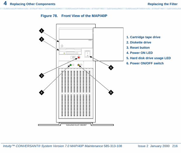
4 Replacing Other Components Replacing the Filter
Intuity™ CONVERSANT® System Version 7.0 MAP/40P Maintenance 585-313-108 Issue 2 January 2000 216
Figure 78. Front View of the MAP/40P
h2mxfnt3 KLVC 081997
1
2
3
4 5
6
1. Cartridge tape drive
2. Diskette drive
3. Reset button
4. Power ON LED
5. Hard disk drive usage LED
6. Power ON/OFF switch

4 Replacing Other Components Replacing the Filter
Intuity™ CONVERSANT® System Version 7.0 MAP/40P Maintenance 585-313-108 Issue 2 January 2000 217
Removing the Filter
To remove the filter for replacement or cleaning, do the following.
1 Remove the vented cover from the lower portion of the bezel by pressing down gently on the top of the cover and pulling out.
2 Remove the filter from the vented cover.
Cleaning the Filter
Cleaning the filter should be a part of routine maintenance. Clean the filter with mild soap and water. Allow it to air dry before you replace it.
! CAUTION:Do not use heat to dry the filter and do not place a wet or damp filter into the MAP/40P.
Installing the Filter
To install the filter, do the following:
1 Place the filter into the vented cover.

4 Replacing Other Components Replacing Memory Modules
Intuity™ CONVERSANT® System Version 7.0 MAP/40P Maintenance 585-313-108 Issue 2 January 2000 218
2 Place the vented cover into the bezel by inserting the lower portion behind the bezel, pressing down gently on the top of the cover, and pushing in toward the chassis.
Replacing Memory Modules
This section describes the memory available with the MAP/40P and includes the following procedures to replace memory modules:
• Identifying a Damaged SIMM on page 221
• Removing SIMMs on page 225
• Installing SIMMs on page 226
! CAUTION:Observe proper electrostatic discharge precautions when you handle computer components. Wear an antistatic wrist strap that touches your bare skin and connect the strap cable to an earth ground. See Protecting Against Damage from Electrostatic Discharge on page 2 in Chapter 1, Getting Inside the Computer .
4 Replacing Other Components Replacing Memory Modules
Intuity™ CONVERSANT® System Version 7.0 MAP/40P Maintenance 585-313-108 Issue 2 January 2000 219
Memory and SIMM Description
The MAP/40P supports 96 Mbytes of memory for the P5 200 MHz CPU circuit card. The memory is packaged on single in-line memory modules (SIMMs). These modules are placed in sockets located in the top left corner of the CPU circuit card (Figure 79 on page 220).
Installation Rules The SIMMs must be installed on the CPU using the following rules:
• All SIMMs must be either -6, 60nS or -7, 70nS speed rating.
• SIMMs must be in matched pairs.
• SIMM1 and SIMM2 must both be equipped.
• SIMM1 and SIMM2 must be identical (same part number, speed, size, vendor).
• If SIMM3 and SIMM4 are equipped they must be identical. SIMM3 and SIMM4 can be different than SIMM1 and SIMM2.

4 Replacing Other Components Replacing Memory Modules
Intuity™ CONVERSANT® System Version 7.0 MAP/40P Maintenance 585-313-108 Issue 2 January 2000 220
Figure 79. CPU Circuit Card SIMM Location
SIMMs Configurations
The SIMMs must be in one of the following configurations:
• 32 Mbytes consisting of two identical 16-Mbyte SIMMs located in the SIMM1 and SIMM2 sockets.
Busactivity
SIMMs
K b

4 Replacing Other Components Replacing Memory Modules
Intuity™ CONVERSANT® System Version 7.0 MAP/40P Maintenance 585-313-108 Issue 2 January 2000 221
• 64 Mbytes consisting of two identical 32-Mbyte SIMMs located in the SIMM1 and SIMM2 sockets.
• 64 Mbytes consisting of two identical 16-Mbyte SIMMs located in the SIMM1 and SIMM2 sockets and two identical 16-Mbyte SIMMs located in the SIMM3 and SIMM4 sockets.
• 96 Mbytes consisting of two identical 32-Mbyte SIMMs located in the SIMM1 and SIMM2 sockets and two identical 16-Mbyte SIMMs located in the SIMM3 and SIMM4 sockets.
• 128 Mbytes consisting of two identical 32-Mbyte SIMMs located in the SIMM1 and SIMM2 sockets and two identical 32-Mbyte SIMMs located in the SIMM3 and SIMM4 sockets.
Note: The Intuity™ CONVERSANT system will not boot if there is an odd number of SIMMs installed.
Identifying a Damaged SIMM
To determine which of the SIMMs is defective, you must test each pair. One pair of SIMMs must be removed and the system then rebooted using the remaining SIMMs to obtain a reading on the amount of memory available.

4 Replacing Other Components Replacing Memory Modules
Intuity™ CONVERSANT® System Version 7.0 MAP/40P Maintenance 585-313-108 Issue 2 January 2000 222
Checking for Proper SIMM Seating
To check for proper SIMM seating, do the following:
1 Verify that the replacement SIMM is on site and appears to be in usable condition, with no obvious shipping damage.
2 If the system is in service, perform the following steps.
a Stop the voice system. See “Administer the Voice System,” in “Common System Procedures,” in the Intuity CONVERSANT System Reference, 585-313-205, for the procedure.
b Shut down the voice system. See “Administer the Voice System,” in “Common System Procedures,” in the Intuity CONVERSANT System Reference, 585-313-205, for the procedure.
c Shut down the Intuity CONVERSANT system. See “Shut down the System,” in “Common System Procedures,” in the Intuity CONVERSANT System Reference, 585-313-205.
3 Remove power from the MAP/40P. See Removing Power from the MAP/40P in Chapter 1, Getting Inside the Computer .
4 Remove the dress cover. See Removing the Dress Cover on page 9 in Chapter 1, Getting Inside the Computer .
5 Carefully remove the CPU circuit card. See Removing a Circuit Card on page 12 in Chapter 2, Installing or Replacing Circuit Cards , for more information on removing the CPU circuit card.

4 Replacing Other Components Replacing Memory Modules
Intuity™ CONVERSANT® System Version 7.0 MAP/40P Maintenance 585-313-108 Issue 2 January 2000 223
6 Verify that all SIMMs are properly seated in their slots. If all are properly seated, continue with the procedure in Checking for Defective SIMMs on page 223.
If one or more of the SIMMs are not properly installed or seated, do the following.
a Properly seat the SIMM.
b Replace the CPU circuit card. See P5 200 MHz CPU Circuit Card on page 80 in Chapter 2, Installing or Replacing Circuit Cards , for more information on removing the CPU circuit card.
c Reboot the system. See “Reboot the System,” in “Common System Procedures,” in the Intuity CONVERSANT System Reference, 585-313-205.
If the system shows an amount of memory:
• Equal to that installed on the card, the problem has been corrected.
• Less than that installed on the card, continue with the next procedure, Checking for Defective SIMMs on page 223.
Checking for Defective SIMMs
To check for defective SIMMs, do the following:
1 Remove one of the SIMMs. See Removing SIMMs on page 225.
2 Install a new SIMM, identical to the SIMM which was removed. See Installing SIMMs on page 226.

4 Replacing Other Components Replacing Memory Modules
Intuity™ CONVERSANT® System Version 7.0 MAP/40P Maintenance 585-313-108 Issue 2 January 2000 224
3 Reinstall the CPU circuit card. See P5 200 MHz CPU Circuit Card on page 80 in Chapter 2, Installing or Replacing Circuit Cards , for more information on installing the CPU circuit card.
4 Restore power to the MAP/40P. See Restoring Power to the MAP/40P on page 10 in Chapter 1, Getting Inside the Computer .
5 Reboot the system. See “Reboot the System,” in “Common System Procedures,” in the Intuity CONVERSANT System Reference, 585-313-205.
6 Verify the amount of memory as the system reboots.
7 If the amount of memory shown by the system is not equal to the amount of memory installed on the card, one of the remaining SIMMs is defective. Complete step a through step c. If the memory is correct continue with step 8.
a Remove power from the MAP/40P. See Removing Power from the MAP/40P on page 6 in Chapter 1, Getting Inside the Computer , for more information on removing the power.
b Replace the SIMM which was removed in Step 1. See Installing SIMMs on page 226, for more information on replacing the SIMM.
c Return to step 1 and continue, removing a second of SIMM.
If the amount of memory shown by the system equals the amount of memory installed on the card, the SIMM you removed is defective.

4 Replacing Other Components Replacing Memory Modules
Intuity™ CONVERSANT® System Version 7.0 MAP/40P Maintenance 585-313-108 Issue 2 January 2000 225
8 Replace the dress cover. See Replacing the Dress Cover on page 10 in Chapter 1, Getting Inside the Computer , for more information on replacing these components.
9 Apply power to the unit. See Restoring Power to the MAP/40P on page 10 in Chapter 1, Getting Inside the Computer .
Removing SIMMs
To remove a SIMM, do the following:
1 Verify that the replacement SIMMs are on site and appear to be in usable condition.
2 If the system is in service, perform the following steps.
a Stop the voice system. See “Administer the Voice System,” in “Common System Procedures,” in the Intuity CONVERSANT System Reference, 585-313-205, for the procedure.
b Shut down the voice system. See “Administer the Voice System,” in “Common System Procedures,” in the Intuity CONVERSANT System Reference, 585-313-205, for the procedure.
c Shut down the Intuity CONVERSANT system. See “Shut down the System,” in “Common System Procedures,” in the Intuity CONVERSANT System Reference, 585-313-205.

4 Replacing Other Components Replacing Memory Modules
Intuity™ CONVERSANT® System Version 7.0 MAP/40P Maintenance 585-313-108 Issue 2 January 2000 226
3 Remove the incoming power. See Removing Power from the MAP/40P on page 6 in Chapter 1, Getting Inside the Computer .
4 Remove the dress cover. See Removing the Dress Cover on page 9 in Chapter 1, Getting Inside the Computer .
5 Remove the CPU circuit card. See Removing a Circuit Card on page 12 in Chapter 2, Installing or Replacing Circuit Cards .
6 Lay the CPU circuit card on a flat, clean, ESD-protected surface.
7 Release the metal snap locks gently at the edge of the SIMM connectors.
8 Rotate the SIMM back and downward to approximately a 60-degree angle.
9 Remove the SIMM.
Installing SIMMs
To install a SIMM, do the following:
1 If the system is in service, perform the following steps.
a Stop the voice system. See “Administer the Voice System,” in “Common System Procedures,” in the Intuity CONVERSANT System Reference, 585-313-205, for the procedure.

4 Replacing Other Components Replacing Memory Modules
Intuity™ CONVERSANT® System Version 7.0 MAP/40P Maintenance 585-313-108 Issue 2 January 2000 227
b Shut down the voice system. See “Administer the Voice System,” in “Common System Procedures,” in the Intuity CONVERSANT System Reference, 585-313-205, for the procedure.
c Shut down the Intuity CONVERSANT system. See “Shut down the System,” in “Common System Procedures,” in the Intuity CONVERSANT System Reference, 585-313-205.
2 Remove the incoming power. See Removing Power from the MAP/40P on page 6 in Chapter 1, Getting Inside the Computer .
3 Remove the dress cover. See Removing the Dress Cover on page 9 in Chapter 1, Getting Inside the Computer .
4 Remove the CPU circuit card. See Removing a Circuit Card on page 12 in Chapter 2, Installing or Replacing Circuit Cards .
5 Install the SIMM by positioning the new SIMM at approximately a 60-degree angle with respect to the CPU circuit card.
All SIMMs are keyed to prevent them from being inserted incorrectly.
Note: Install a new SIMM in the slot adjacent to the last SIMM installed. Do not leave any empty sockets between SIMMS.
6 Push down at that angle until the SIMM is reset into the SIMM carrier.
7 Snap the SIMM into place by rotating it to an upright position.

4 Replacing Other Components Replacing Memory Modules
Intuity™ CONVERSANT® System Version 7.0 MAP/40P Maintenance 585-313-108 Issue 2 January 2000 228
The metal snap lock on the ends of the connector for the SIMM will be forced open and then lock when in the upright position.
8 Ensure the connector guide pins are seated into the clearance holes provided at each end of the SIMM.
When properly seated, the guides should be fully extended into the circuit card clearance holes.
9 Reinstall the CPU circuit card. See Installing a Circuit Card on page 14 in Chapter 2, Installing or Replacing Circuit Cards .
10 Reboot the system. See “Reboot the System,” in “Common System Procedures,” in the Intuity CONVERSANT System Reference, 585-313-205.
11 Verify the amount of memory as the system reboots.
12 Replace the dress cover. See Replacing the Dress Cover on page 10 in Chapter 1, Getting Inside the Computer .
13 Apply power to the MAP/40P. See Restoring Power to the MAP/40P on page 10 in Chapter 1, Getting Inside the Computer .

4 Replacing Other Components Replacing the Power ON/OFF Switch
Intuity™ CONVERSANT® System Version 7.0 MAP/40P Maintenance 585-313-108 Issue 2 January 2000 229
Replacing the Power ON/OFF Switch
The power ON/OFF switch is located in the front of the MAP/40P (Figure 65 on page 179).
Removing the Power ON/OFF Switch
To remove the power ON/OFF switch, do the following:
1 Verify that the replacement equipment is on site and appears to be in usable condition, with no obvious shipping damage.
2 If the system is in service, perform the following Steps a and b.
a Stop the voice system. See “Administer the Voice System,” in “Common System Procedures,” in the Intuity CONVERSANT System Reference, 585-313-205, for the procedure.
b Shut down the voice system. See “Administer the Voice System,” in “Common System Procedures,” in the Intuity CONVERSANT System Reference, 585-313-205, for the procedure.
c Shut down the Intuity CONVERSANT system. See “Shut down the System,” in “Common System Procedures,” in the Intuity CONVERSANT System Reference, 585-313-205.
3 Remove the incoming power. See Removing Power from the MAP/40P on page 6 in Chapter 1, Getting Inside the Computer .

4 Replacing Other Components Replacing the Power ON/OFF Switch
Intuity™ CONVERSANT® System Version 7.0 MAP/40P Maintenance 585-313-108 Issue 2 January 2000 230
4 Remove dress cover. See Removing the Dress Cover on page 9 in Chapter 1, Getting Inside the Computer .
5 Remove the four wires which attach to the back of the power ON/OFF switch (Figure 80 on page 230).
Figure 80. Power ON/OFF Switch
1
1
4
4
swmxpowr LJK 081597
3
3
2
2
5
6
1. Black wire
2. Brown wire
3. White wire
4. Blue wire
5. ON symbol
6. OFF symbol

4 Replacing Other Components Replacing the Power Supply
Intuity™ CONVERSANT® System Version 7.0 MAP/40P Maintenance 585-313-108 Issue 2 January 2000 231
Replacing the Power Supply
The 110/220-VAC power supply is located in the upper right corner of the MAP/40P as shown in Figure 65 on page 179.
Removing the Power Supply
To remove the power supply, do the following:
1 Verify that the replacement equipment is on site and appears to be in usable condition, with no obvious shipping damage.
2 If the system is in service, perform the following Steps a, b and c.
a Stop the voice system. See “Administer the Voice System,” in “Common System Procedures,” in the Intuity CONVERSANT System Reference, 585-313-205, for the procedure.
b Shut down the voice system. See “Administer the Voice System,” in “Common System Procedures,” in the Intuity CONVERSANT System Reference, 585-313-205, for the procedure.
c Shut down the Intuity CONVERSANT system. See “Shut down the System,” in “Common System Procedures,” in the Intuity CONVERSANT System Reference, 585-313-205.
3 Remove the incoming power. See Removing Power from the MAP/40P on page 6 in Chapter 1, Getting Inside the Computer .

4 Replacing Other Components Replacing the Power Supply
Intuity™ CONVERSANT® System Version 7.0 MAP/40P Maintenance 585-313-108 Issue 2 January 2000 232
4 Remove dress cover. See Removing the Dress Cover on page 9 in Chapter 1, Getting Inside the Computer .
5 Unplug the connector to the cartridge tape drive (Figure 81 on page 233).
6 Unplug the connector to the diskette drive (Figure 81 on page 233).
7 Unplug the connector to the second hard disk drive, if provided.
8 Unplug the connector to the first hard disk drive (Figure 81 on page 233).

4 Replacing Other Components Replacing the Power Supply
Intuity™ CONVERSANT® System Version 7.0 MAP/40P Maintenance 585-313-108 Issue 2 January 2000 233
Figure 81. MAP/40P Power Supply Unit
pcmxmp40 RPY 081997
1
2
3
4
5
6
7
89
1. Cartridge tape drive power connection
2. Diskette drive power connection
3. Power ON/OFF switch
4. Reset button
5. Hard Disk Drive 1 power connection
6. Hard Disk Drive 0 power connection
7. Backplane power connection
8. Backplane power connection
9. Backplane power connection

4 Replacing Other Components Replacing the Power Supply
Intuity™ CONVERSANT® System Version 7.0 MAP/40P Maintenance 585-313-108 Issue 2 January 2000 234
9 Remove the circuit cards in PCI slots 1, 2, and 3.
This is necessary to provide enough clearance to remove the power supply unit from the chassis.
10 Remove the SCSI cable from the P5 200 MHz circuit card.
This is necessary to provide adequate clearance to access the backplane power supply connectors.
11 Remove the diskette cable from the P5 200 MHz circuit card.
This is necessary to provide adequate clearance to access the backplane power supply connectors.
12 Disconnect the four wires connecting the output power cord to the power on switch (Figure 81 on page 233).
13 Remove the four screws on the chassis rear area that secure the power supply unit.
14 Slide the unit slightly forward towards the front of the chassis and tilt towards the backplane.
15 Lift and remove the power supply.
4 Replacing Other Components Replacing the Power Supply
Intuity™ CONVERSANT® System Version 7.0 MAP/40P Maintenance 585-313-108 Issue 2 January 2000 235
Installing a Power Supply
To install the power supply, do the following:
1 Remove the spare power supply unit from the shipping carton.
Note: Keep the package and all ESD-protective wrapping to return the defective unit. Re-use of the original replacement unit packaging is necessary to meet the manufacturer’s warranty.
2 Install the power supply unit into the chassis and align the screw holes.
3 Install the four screws on the chassis rear area that secure the power supply unit.
4 Attach the power supply DC output connectors to the backplane connectors.
5 Attach the four wires connecting the output power cord to the power on switch (Figure 81 on page 233).
6 Attach the connector to the second hard disk drive, if provided.
If a second hard disk drive is not installed, dress this lead back out of the way to reduce cable congestion as previously outlined (Figure 81 on page 233).
7 Attach the connector to the first hard disk drive (Figure 81 on page 233).
8 Attach the connector to the cartridge tape drive (Figure 81 on page 233).

4 Replacing Other Components Replacing the Power Supply
Intuity™ CONVERSANT® System Version 7.0 MAP/40P Maintenance 585-313-108 Issue 2 January 2000 236
9 Attach the connector to the diskette drive (Figure 81 on page 233).
10 Connect the SCSI cable to the P5 200 MHz CPU circuit card.
11 Connect the diskette cable to the P5 200 MHz CPU circuit card.
12 Reinstall the circuit cards you removed from PCI slots 1, 2, and 3. See Installing a Circuit Card on page 14 in Chapter 2, Installing or Replacing Circuit Cards .
13 Apply power to the MAP/40P. See Restoring Power to the MAP/40P on page 10 in Chapter 1, Getting Inside the Computer .
14 Verify that the replacement power supply unit is functioning properly by doing the following:
a Measure the backplane +5V, -5V +12V and -12V voltages.
b Make sure the card cage fans are operating.
15 Replace the dress cover. See Replacing the Dress Cover on page 10 in Chapter 1, Getting Inside the Computer .

4 Replacing Other Components Replacing a Terminator SIP
Intuity™ CONVERSANT® System Version 7.0 MAP/40P Maintenance 585-313-108 Issue 2 January 2000 237
Replacing a Terminator SIP
If the circuit card is the last circuit card connected to either end of the TDM bus, you must ensure that the TDM bus terminator single in-line packages (SIPs) are in place on the circuit card. If the circuit card is not the last circuit card on the bus, you must remove the SIPs.
Note: “Last circuit card connected” means that there are no other cards between the circuit card and the end of the bus. There may, however, be empty connectors.
To replace a terminator SIP, complete the following:
1 Align the terminator SIP with the SIP socket on the circuit card (Figure 82 on page 238).
There are markings on both the terminator SIP and the circuit card which should be used to align the terminator SIP.
2 Insert the terminator SIP.

4 Replacing Other Components Replacing a Terminator SIP
Intuity™ CONVERSANT® System Version 7.0 MAP/40P Maintenance 585-313-108 Issue 2 January 2000 238
Figure 82. Replacing Terminator SIPs on the TDM Bus
SIP socket
• Dot or squareOR
• The number 1
Pin 1 placementon the PWB
TDM SIPterm inatingresistors (2)
Printed wiringboard (PWB)
Various locations forcomponent pin 1 orientation

Intuity™ CONVERSANT® System Version 7.0 MAP/40P Maintenance 585-313-108 Issue 2 January 2000 239
5 Installing the Tip/Ring DistributionHardware
Overview
As the number of lines served by the Lucent Intuity system increases, the number of 6-pin modular cords also increases. These 6-pin modular cords connect the system with the customer-premises equipment or the on-premises terminal block provided by the central office.
Optional Tip/Ring distribution hardware is available to help simplify the wiring scheme.
This chapter describes the two types of Tip/Ring distribution hardware and the proper installation procedures for them.
Capacity
The Tip/Ring distribution hardware allows you to connect to a maximum of 48 channels (eight Tip/Ring circuit cards) through two 25-pair, high-density cables (RJ21X).

Intuity™ CONVERSANT® System Version 7.0 MAP/40P Maintenance 585-313-108 Issue 2 January 2000 240
5 Installing the Tip/Ring Distribution Hardware Types of Tip/Ring Distribution Hardware
Types of Tip/Ring Distribution Hardware
There are two types of Tip/Ring distribution hardware:
• Distribution hardware with a 356B adapter
• Distribution panel without a 356B adapter
Tip/Ring Distribution Hardware with a 356B Adapter
The Tip/Ring distribution hardware with the 356B adapter (Figure 83 on page 241) comes in a kit which consists of:
• A 356B adapter
• An adapter bracket
• A mounting plate
• A 25-pair, high-density cable for the first 24 channels
Note: An additional 25-pair, high-density cable is required for the second 24 channels to be supported by the distribution panel. Therefore, if you are connecting 48 channels, you will need another cable that is not part of this kit.

5 Installing the Tip/Ring Distribution Hardware
Intuity™ CONVERSANT® System Version 7.0 MAP/40P Maintenance 585-313-108 Issue 2 January 2000 241
Types of Tip/Ring Distribution Hardware
Figure 83. Assembly of MAP/40P Tip/Ring Distribution Hardware with 356B Adapter
1
1
2
2
3
3
4
4
5
5
6
6
78
9
adcv356t LJK 052797
1. Adapter clip
2. 356B adapter
3. Grounding plug
4. Grounding wire
5. 25-pin cable
6. Connector
7. Tip/Ring cords
8. Modular jacks
9. Grounding tab

Intuity™ CONVERSANT® System Version 7.0 MAP/40P Maintenance 585-313-108 Issue 2 January 2000 242
5 Installing the Tip/Ring Distribution Hardware Types of Tip/Ring Distribution Hardware
Tip/Ring Distribution Hardware without a 356B Adapter
The Tip/Ring distribution hardware without the 356B adapter (Figure 84 on page 243) comes in a kit which consists of:
• A distribution panel with a circuit pack assembly mounted in its base
• A top cover plate
• A 25-pair, high-density cable for the first 24 channels
Note: An additional 25-pair, high-density cable is required for the second 24 channels to be supported by the distribution panel. Therefore, if you are connecting 48 channels, you will need another cable that is not part of this kit.

5 Installing the Tip/Ring Distribution Hardware
Intuity™ CONVERSANT® System Version 7.0 MAP/40P Maintenance 585-313-108 Issue 2 January 2000 243
Types of Tip/Ring Distribution Hardware
Figure 84. MAP/40P Tip/Ring Distribution Hardware Assembly without 356B Adapter

Intuity™ CONVERSANT® System Version 7.0 MAP/40P Maintenance 585-313-108 Issue 2 January 2000 244
5 Installing the Tip/Ring Distribution Hardware Installing and Connecting the Tip/Ring Distribution Hardware with
the 356B Adapter
Installing and Connecting the Tip/Ring DistributionHardware with the 356B Adapter
! CAUTION:Observe proper electrostatic discharge precautions when you handle computer components. Wear an antistatic wrist strap that touches your bare skin and connect the strap cable to an earth ground. See Protecting Against Damage from Electrostatic Discharge on page 2 in Chapter 1, Getting Inside the Computer .
Installing the Tip/Ring Distribution Hardware with the 356B Adapter
1 Verify that the distribution hardware is on site and appears to be in usable condition.
2 If the system is currently connected to the telephone network, notify the service provider that the system is about to be disconnected. The service provider will ask which extensions will be affected.
3 If the system is in service, perform Steps a and b.
a Stop the voice system. See “Administer the Voice System,” in “Common System Procedures,” in the Intuity CONVERSANT System Reference, 585-313-205, for the procedure.

5 Installing the Tip/Ring Distribution Hardware
Intuity™ CONVERSANT® System Version 7.0 MAP/40P Maintenance 585-313-108 Issue 2 January 2000 245
Installing and Connecting the Tip/Ring Distribution Hardware withthe 356B Adapter
b Shut down the system. See “Shut Down the System,” in “Common System Procedures,” in the Intuity CONVERSANT System Reference, 585-313-205.
4 Remove the incoming power. See Removing Power from the MAP/40P on page 6 in Chapter 1, Getting Inside the Computer .
5 Remove dress cover and access panel. See Chapter 1, Getting Inside the Computer .
6 Verify that all of the necessary components are included. See Figure 83 on page 241 for the components.
7 Place the MAP/40P on its side and install the distribution mounting plate below the circuit card cage on the bottom of the MAP/40P (Figure 83 on page 241).
8 Locate the two mounting holes which are parallel to those used to mount the support base.
9 Attach the short end of the mounting plate to the two mounting holes with the two screws provided. The end of the mounting plate should rest against the support base.
10 Return the MAP/40P to an upright position.
11 Install the u-shaped adapter brackets with the screws provided. Attach the brackets to the mounting plate.

Intuity™ CONVERSANT® System Version 7.0 MAP/40P Maintenance 585-313-108 Issue 2 January 2000 246
5 Installing the Tip/Ring Distribution Hardware Installing and Connecting the Tip/Ring Distribution Hardware with
the 356B Adapter
The u-shape of the bracket should face out with the grounding lug towards the MAP/40P top surface (Figure 83 on page 241).
12 Plug the 3-foot, 6-pin modular cords from the Tip/Ring cards into the 356B adapters. Each adapter can accommodate eight modular cords (Figure 83 on page 241).
13 Using the connector provided, attach the 25-pair, high-density cable to the 356B adapter.
14 Snap the 356B adapters into the adapter bracket. Ensure the modular cords are inside the adapter bracket.
Note: The 356B adapters can be removed by spreading the bracket sides apart.
! CAUTION:The 25-pair, high-density cables should come from the top of the adapter brackets.
15 Connect the grounding wire and strap to the top of the adapter bracket.

5 Installing the Tip/Ring Distribution Hardware
Intuity™ CONVERSANT® System Version 7.0 MAP/40P Maintenance 585-313-108 Issue 2 January 2000 247
Installing and Connecting the Tip/Ring Distribution Hardwarewithout the 356B Adapter
Connecting the Tip/Ring Distribution Hardwarewith the 356B Adapter
The numbering scheme for pinouts and channels which shows how to connect the short modular cords provided with the Tip/Ring cards to the distribution hardware is shown in Tip/Ring Circuit Cards on page 17 in Chapter 2, Installing or Replacing Circuit Cards .
Referring to those tables and using the channel numbers on the Tip/Ring cards and the number of the Tip/Ring circuit cards in the system, connect the Tip/Ring card modular jacks to the appropriate jacks on the 356B connectors.
Installing and Connecting the Tip/Ring DistributionHardware without the 356B Adapter
! CAUTION:Observe proper electrostatic discharge precautions when you handle computer components. Wear an antistatic wrist strap that touches your bare skin and connect the strap cable to an earth ground. See Protecting Against Damage from Electrostatic Discharge on page 2 in Chapter 1, Getting Inside the Computer .

Intuity™ CONVERSANT® System Version 7.0 MAP/40P Maintenance 585-313-108 Issue 2 January 2000 248
5 Installing the Tip/Ring Distribution Hardware Installing and Connecting the Tip/Ring Distribution Hardware
without the 356B Adapter
Installing the Tip/Ring Distribution Hardware without the 356B Adapter
1 Make sure that the Tip/Ring distribution hardware assembly kit is on site and appears to be in usable condition.
2 Verify that all of the necessary components are included. See Figure 83 on page 241 for the components.
3 If you are currently connected to the telephone network, notify the service provider that you are disconnecting.
They will ask you which extensions will be affected.
4 If the system is in service, perform Steps a and b.
a Stop the voice system. See “Administer the Voice System,” in “Common System Procedures,” in the Intuity CONVERSANT System Reference, 585-313-205, for the procedure.
b Shut down the system. See “Shut down the System,” in “Common System Procedures,” in the Intuity CONVERSANT System Reference, 585-313-205.
Connecting the Tip/Ring Distribution Hardware without the 356B Adapter
1 Remove the seven screws that secure the distribution panel cover.
2 Put the distribution panel cover aside.

5 Installing the Tip/Ring Distribution Hardware
Intuity™ CONVERSANT® System Version 7.0 MAP/40P Maintenance 585-313-108 Issue 2 January 2000 249
Installing and Connecting the Tip/Ring Distribution Hardwarewithout the 356B Adapter
3 Table 16 on page 249 shows the numbering scheme for connecting the short modular cords provided with the Tip/Ring circuit cards to the panel.
Use this information, the channel numbers on the Tip/Ring circuit cards, and the number of Tip/Ring circuit cards in the system to connect the Tip/Ring circuit card modular jacks to the appropriate jacks on the Tip/Ring distribution panel.
Table 16. Connecting the Modular Cords from the MAP/40P Tip/Ring Circuit Cards to the Tip/Ring Distribution Panel
Tip/Ring Card
Channel Numbers on Tip/Ring Card
Jack Number on Distribution Panel
1st 1, 2, 3 J1
4, 5, 6 J2
2nd 1, 2, 3 J3
4, 5, 6 J4
3rd 1, 2, 3 J5
4, 5, 6 J6
4th 1, 2, 3 J7
4, 5, 6 J81 of 2

Intuity™ CONVERSANT® System Version 7.0 MAP/40P Maintenance 585-313-108 Issue 2 January 2000 250
5 Installing the Tip/Ring Distribution Hardware Installing and Connecting the Tip/Ring Distribution Hardware
without the 356B Adapter
4 Make telephone line connections to the MAP/40P with the 25-pair, high-density cable(s) equipped with USOC RJ21X connections.
5 Mount the rear cover plate to the distribution panel cover with the four screws provided.
6 Mount the Tip/Ring distribution panel on a wall or cabinet or allow it to rest on a shelf or the floor.
5th 1, 2, 3 J9
4, 5, 6 J10
6th 1, 2, 3 J11
4, 5, 6 J12
7th 1, 2, 3 J13
4, 5, 6 J14
8th 1, 2, 3 J15
4, 5, 6 J16
Table 16. Connecting the Modular Cords from the MAP/40P Tip/Ring Circuit Cards to the Tip/Ring Distribution Panel
Tip/Ring Card
Channel Numbers on Tip/Ring Card
Jack Number on Distribution Panel
2 of 2

5 Installing the Tip/Ring Distribution Hardware
Intuity™ CONVERSANT® System Version 7.0 MAP/40P Maintenance 585-313-108 Issue 2 January 2000 251
Completing the Installation
Completing the Installation
To complete the installation and put the system back in service, do the following:
1 Replace the circuit card access panel and the dress cover and reconnect the keyboard, and the monitor. See Replacing the Dress Cover on page 10 in Chapter 1, Getting Inside the Computer .
2 Apply power to the MAP/40P. See Restoring Power to the MAP/40P on page 10 in Chapter 1, Getting Inside the Computer .
3 Run diagnostics to verify the hardware is functioning properly. See “Diagnostics,” in the Intuity CONVERSANT System Reference, 585-313-205 for more information on running the diagnostics.
4 Notify the service provider that the system is back online, if necessary.

Intuity™ CONVERSANT® System Version 7.0 MAP/40P Maintenance 585-313-108 Issue 2 January 2000 252
6 Installing Base System Software
Overview
This chapter describes the installation procedures necessary to reload the UnixWare operating system software on a computer that has experienced a disk failure.
Use this chapter in conjunction with Appendix D, Disaster Recovery Checklists.
Note: The installer must have the root password to complete these procedures.

6 Installing Base System Software Installing Base System Software
Intuity™ CONVERSANT® System Version 7.0 MAP/40P Maintenance 585-313-108 Issue 2 January 2000 253
Installing Base System Software
Note: Installing the UnixWare operating system unmounts file systems. If this software is being loaded onto a system that has clean hard disks that have not been previously loaded, the system will not detect file systems. If this is a recovery installation, the system will detect previously loaded file systems.
Beginning the UnixWare Installation
To load software onto a new or used disk, do the following:
1 Insert the diskette labeled “Intuity CONVERSANT 7 Intuity UnixWare 2.1.2 Boot Floppy 1” into the diskette drive.
2 If the system is off, turn it on using the power switch on the front of the MAP/40P. See Restoring Power to the MAP/40P on page 10 in Chapter 1, Getting Inside the Computer .
If the system is on, reboot the system. See “Reboot the System,” in “Common System Procedures,” in the Intuity CONVERSANT System Reference, 585-313-205.

6 Installing Base System Software Installing Base System Software
Intuity™ CONVERSANT® System Version 7.0 MAP/40P Maintenance 585-313-108 Issue 2 January 2000 254
The system displays the SCO introduction screen as it begins to load the base system software. When the system has loaded the first boot floppy it displays the following message:
Insert the second floppy and press ENTER.
3 Remove the diskette labeled “Intuity CONVERSANT 7 Intuity UnixWare 2.1.2 Boot Floppy 1” from the diskette drive.
4 Insert the diskette labeled “Intuity CONVERSANT 7 Intuity UnixWare 2.1.2 Boot Floppy 2” into the diskette drive.
5 Press ENTER.
The system displays the following message:
Please wait while the system software drivers are loaded.
After approximately 2 minutes the system displays the SCO UnixWare 2.1 menu (Figure 85 on page 255).

6 Installing Base System Software Installing Base System Software
Intuity™ CONVERSANT® System Version 7.0 MAP/40P Maintenance 585-313-108 Issue 2 January 2000 255
Figure 85. Start-Up Screen
6 Press the down arrow to move to Install/Upgrade UnixWare 2.1 and press ENTER .
The system displays the Remove Floppy screen (Figure 86 on page 255).
Figure 86. Remove Floppy Screen
SCO UnixWare 2.1 Menu
Install/Upgrade UnixWare 2.1Access UnixWare ShelllMount File SystemsReboot
Use up/down arrow keys and ENTER to select; F1 for help
UnixWare Installation Remove Floppy
Remove the Floppy for the floppy drive
Press ‘ENTER’ to continue

6 Installing Base System Software Installing Base System Software
Intuity™ CONVERSANT® System Version 7.0 MAP/40P Maintenance 585-313-108 Issue 2 January 2000 256
7 Remove the diskette labeled “Intuity CONVERSANT 7 Intuity UnixWare 2.1.2 Boot Floppy 2” from the diskette drive.
8 Press ENTER.
The system displays the Introduction screen (Figure 87 on page 256).
Figure 87. Introduction Screen
UnixWare Installation Introduction
Welcome to the UnixWare installation process!
If you have never installed UnixWare before, it is recommended that you press the ’F1’ (or ’?’) key now to learn more about the installation process and the hardware requirements of UnixWare.
-Pressing the ’F1’ (or ’?’) key at any time during installation will display more information or help.
-Pressing the ’Del’ key at any time cancels the installation.
Press the ’F1’ (or ’?’) key for more information or ’ENTER’ to continue.

6 Installing Base System Software Installing Base System Software
Intuity™ CONVERSANT® System Version 7.0 MAP/40P Maintenance 585-313-108 Issue 2 January 2000 257
! CAUTION:If you press DELETE to stop the UnixWare installation at any time during this process, you will have to restart the software installation process at step 1.
9 Continue with the procedure in Setting Up the UnixWare Environment on page 257.
Setting Up the UnixWare Environment
To set up the UnixWare Environment, complete the following:
1 Starting at the Introduction Screen (Figure 87 on page 256), press ENTER.
The system displays the Keyboard Setup screen (Figure 88 on page 258).
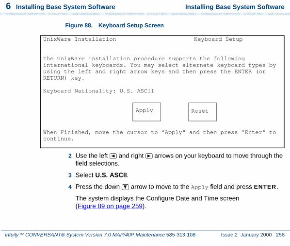
6 Installing Base System Software Installing Base System Software
Intuity™ CONVERSANT® System Version 7.0 MAP/40P Maintenance 585-313-108 Issue 2 January 2000 258
Figure 88. Keyboard Setup Screen
2 Use the left and right arrows on your keyboard to move through the field selections.
3 Select U.S. ASCII.
4 Press the down arrow to move to the Apply field and press ENTER .
The system displays the Configure Date and Time screen(Figure 89 on page 259).
UnixWare Installation Keyboard Setup
The UnixWare installation procedure supports the following international keyboards. You may select alternate keyboard types by using the left and right arrow keys and then press the ENTER (or RETURN) key.
Keyboard Nationality: U.S. ASCII
When Finished, move the cursor to "Apply" and then press "Enter" to continue.
Apply Reset

6 Installing Base System Software Installing Base System Software
Intuity™ CONVERSANT® System Version 7.0 MAP/40P Maintenance 585-313-108 Issue 2 January 2000 259
Figure 89. Configure Date and Time Screen
5 Use the left and right arrows on your keyboard to move through the field selections. Use the down arrow to move to the next field.
6 Select the appropriate data for each field.
UnixWare Installation Configure Date and TimeOn this screen, you will check the current date and time that is set on your computer and change them if necessary. You also select what timezone configuration you require. Either set a continent(s) which will lead you onto a further screen with locations or manual entry for a custom timezone.
The current date:The current Time:Enter the current year:Enter the month of the year (1-12):Enter the day of the month(1-31):Enter the hour of the day (0-23):Enter the minute of the hour (0-59):Timezone configuration:
Press ‘TAB’ to move the cursor between fields. When finished, move the cursor to ‘APPLY’ and then press ‘ENTER’ to continue.
Apply Reset

6 Installing Base System Software Installing Base System Software
Intuity™ CONVERSANT® System Version 7.0 MAP/40P Maintenance 585-313-108 Issue 2 January 2000 260
7 Press the down arrow to move to the Apply field and press ENTER .
The system displays the Continent Location Choice screen (Figure 90 on page 260).
Figure 90. Continent Location Choice Screen
8 Use the left and right arrows on your keyboard to move through the field selections.
9 Select the appropriate data for each field.
UnixWare Installation Continent Location Choice Screen
On this screen you choose the country/location you are in, having already selected the continent. To go back to the continent screen select ‘Back One Screen’. Use the left and right arrow keys.
Location
Press ‘TAB’ to move the cursor between fields. When finished, move the cursor to ‘APPLY’ and then press ‘ENTER’ to continue.
Apply Reset

6 Installing Base System Software Installing Base System Software
Intuity™ CONVERSANT® System Version 7.0 MAP/40P Maintenance 585-313-108 Issue 2 January 2000 261
10 Press the down arrow to move to the Apply field and press ENTER .
The system displays the Installation Type Selection screen (Figure 91 on page 261).
Figure 91. Installation Type Selection Screen
11 Use the left and right arrows on your keyboard to move through the field selections. Use the down arrow to move to the next field.
UnixWare Installation Installation Type Selection
You must choose a system type. The system type you choose will determine the default file system sizes you will specify on the next screen.
Press the ‘F1’ or ‘?’ key to see more information about these different system types.
Platform Type:CPU Type:Offer Type:
Press ‘TAB’ to move between fields. Press ‘ENTER’ to apply
Apply Reset

6 Installing Base System Software Installing Base System Software
Intuity™ CONVERSANT® System Version 7.0 MAP/40P Maintenance 585-313-108 Issue 2 January 2000 262
12 Select the appropriate data for each field as specified in Table 17 on page 262.
13 Press the down arrow to move to the Apply field and press ENTER .
Note: If the system displays a message that the system must have at least 60 MByte of space in the hard disk drive to install UNIX, the hard disk drive is experiencing problems. The cable may not be connected, or the hard disk drive may be damaged. Power down the system and check the hard disk drive cables. See Removing the Dress Cover on page 9 in Chapter 1, Getting Inside the Computer , for the procedure.
The system displays the Primary Hard Disk Partitioning screen (Figure 92 on page 263).
Table 17. Installation Type Selection Screen Entries
Field Setting
Platform type: MAP/40P
CPU type: Pentium/SCSI
Offer type: Intuity CONVERSANT

6 Installing Base System Software Installing Base System Software
Intuity™ CONVERSANT® System Version 7.0 MAP/40P Maintenance 585-313-108 Issue 2 January 2000 263
Figure 92. Primary Hard Disk Partitioning Screen
14 Continue with the procedure in Initializing the Hard Disk Drives on page 264.
UnixWare Installation Primary Hard Disk Partitioning
In order to install UnixWare, you must reserve a partition (a portion of your hard disk’s space) on your primary hard disk for the UNIX System. After you press ‘ENTER’ you will be shown a screen that will allow you to create new partitions, delete existing partitions or change the active partition of your primary hard disk (the partition that your computer will boot from).
WARNING: All files in any partition(s) you delete will be destroyed. If you wish to attempt to preserve any files from an existing UNIX System, do not delete its partition(s).
The UNIX System partition that you intend to use on the primary hard disk must be at least 120 MBs and labeled ‘ACTIVE.’
Press ‘ENTER’ to continue

6 Installing Base System Software Installing Base System Software
Intuity™ CONVERSANT® System Version 7.0 MAP/40P Maintenance 585-313-108 Issue 2 January 2000 264
Initializing the Hard Disk Drives
To partition the hard disk drives, do the following:
1 Starting at the Primary Hard Disk Partitioning screen (Figure 92 on page 263), press ENTER .
The system displays the Hard Disk Partitioning, Disk 1 screen (Figure 93 on page 264).
Figure 93. .Hard Disk Partitioning, Disk 1 Screen
2 Enter 2
UnixWare Installation Hard Disk Partitioning - Disk 1
Total disk size is 2047 cylinders (4094.0 MB)
Partition Status Type Start End Length % ApproxMB
1. Overwrite system master boot code2. Create a partition3. Change Active (Boot from) partition4. Cancel (Exit without updating disk configuration)
Enter Selection:
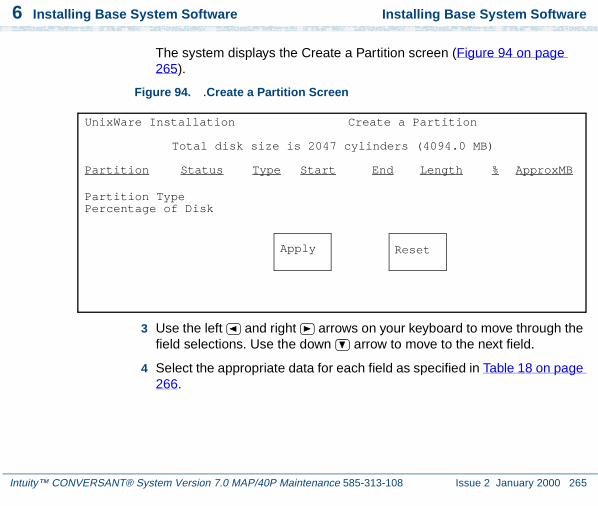
6 Installing Base System Software Installing Base System Software
Intuity™ CONVERSANT® System Version 7.0 MAP/40P Maintenance 585-313-108 Issue 2 January 2000 265
The system displays the Create a Partition screen (Figure 94 on page 265).
Figure 94. .Create a Partition Screen
3 Use the left and right arrows on your keyboard to move through the field selections. Use the down arrow to move to the next field.
4 Select the appropriate data for each field as specified in Table 18 on page 266.
UnixWare Installation Create a Partition
Total disk size is 2047 cylinders (4094.0 MB)
Partition Status Type Start End Length % ApproxMB
Partition TypePercentage of Disk
Apply Reset

6 Installing Base System Software Installing Base System Software
Intuity™ CONVERSANT® System Version 7.0 MAP/40P Maintenance 585-313-108 Issue 2 January 2000 266
5 Press the down arrow to move to the Apply field and press ENTER .
The system displays the Hard Disk Partitioning, Disk 1 screen (Figure 95 on page 267).
Table 18. Create a Partition Screen Entries
Field Setting
Partition type: UNIX System
Percentage of Disk: 100

6 Installing Base System Software Installing Base System Software
Intuity™ CONVERSANT® System Version 7.0 MAP/40P Maintenance 585-313-108 Issue 2 January 2000 267
Figure 95. Hard Disk Partitioning, Disk 1 Screen
6 Press ENTER.
The system displays the Hard Disk Partitioning, Disk 1 screen (Figure 96 on page 268).
Total disk size is 2047 cylinders (4094.0MB)
Cylinders
Partition Status Type Start End Length % ApproxMB
1 Active UNIX 0 2046 2047 100 4094System
1. Overwrite system master boot code2. Change Active (Boot from) partition3. Delete a partition4. Cancel (Exit without updating disk configuration)
Enter Selection:

6 Installing Base System Software Installing Base System Software
Intuity™ CONVERSANT® System Version 7.0 MAP/40P Maintenance 585-313-108 Issue 2 January 2000 268
Figure 96. Hard Disk Partitioning, Disk 1 Screen
7 Enter 2
The system displays the Change Active Partition screen Figure 97 on page 269.
Total disk size is 2047 cylinders (4094.0MB)
Cylinders
Partition Status Type Start End Length % ApproxMB
1 Active UNIX 0 2046 2047 100 4094System
1. Do not overwrite system master boot code2. Change Active (Boot from) partition3. Delete a Partition4. Cancel (Exit without updating disk configuration)
Enter Selection:
System master boot code will be overwritten

6 Installing Base System Software Installing Base System Software
Intuity™ CONVERSANT® System Version 7.0 MAP/40P Maintenance 585-313-108 Issue 2 January 2000 269
Figure 97. Change Active Partition Screen
8 Press ENTER
The system displays the Hard Disk Partitioning, Disk 1 screen Figure 98 on page 270.
UnixWare Installation Change Active Partition
Total disk size is 2047 cylinders (4094.0 MB)
Partition Status Type Start End Length % ApproxMB
1 Active UNIX 0 2046 2047 100 4094System
1. Partition 1
Enter the number of partition you want to boot from:
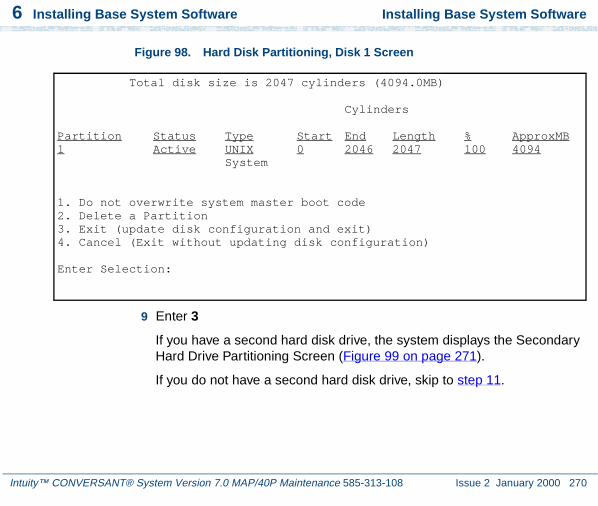
6 Installing Base System Software Installing Base System Software
Intuity™ CONVERSANT® System Version 7.0 MAP/40P Maintenance 585-313-108 Issue 2 January 2000 270
Figure 98. Hard Disk Partitioning, Disk 1 Screen
9 Enter 3
If you have a second hard disk drive, the system displays the Secondary Hard Drive Partitioning Screen (Figure 99 on page 271).
If you do not have a second hard disk drive, skip to step 11.
Total disk size is 2047 cylinders (4094.0MB)
Cylinders
Partition Status Type Start End Length % ApproxMB1 Active UNIX 0 2046 2047 100 4094
System
1. Do not overwrite system master boot code2. Delete a Partition3. Exit (update disk configuration and exit)4. Cancel (Exit without updating disk configuration)
Enter Selection:

6 Installing Base System Software Installing Base System Software
Intuity™ CONVERSANT® System Version 7.0 MAP/40P Maintenance 585-313-108 Issue 2 January 2000 271
Figure 99. Secondary Hard Disk Partitioning Screen
10 Enter 1
The system displays the UnixWare Installation Set Slice Sizes screen (Figure 100 on page 272).
You may use a partition of your secondary hard disk for the UNIX system. If you choose to use a partition of your secondary hard disk you will be shown a screen that will allow you to partition your secondary hard disk.
WARNING: All files in any partition(s) you delete will be destroyed.
If you choose to create a UNIX System partition on your secondary hard disk, it must be at least 40 MBs.
Your Options are:1. Do not use a partition of the secondary hard disk for
the UNIX System.2. Use a partition of the secondary hard disk for the
UNIX System.
Press ‘1’ or ‘2’ followed by ‘ENTER’.

6 Installing Base System Software Installing Base System Software
Intuity™ CONVERSANT® System Version 7.0 MAP/40P Maintenance 585-313-108 Issue 2 January 2000 272
Figure 100. UnixWare Installation Set Slice Sizes Screen
11 Use the left and right arrows on your keyboard to move through the field selections. Use the down arrow to move to the next field.
UnixWare Installation Set up File Systems on Disk(s)
Enter filesystem sizes on first disk.
Size of / in MB: xx Size of /stand in MB: xx Size of /dev/dump in MB: xx Size of /dev/swap in MB: xx Size of /mtce in MB: xx Size of /vs in MB: xx Size of /oracle in MB: xx Size of /tmp in MB: xx Size of /voice1 in MB: xx Size of /voxem in MB: xx
Consult software installation manual for correct sizes.Megabytes in active partition: Disk 1 - 2063
Apply Reset

6 Installing Base System Software Installing Base System Software
Intuity™ CONVERSANT® System Version 7.0 MAP/40P Maintenance 585-313-108 Issue 2 January 2000 273
12 Enter the appropriate number of megabytes of space needed for each slice as specified in Table 19 on page 273.
Note: The sizes listed in Table 19 on page 273 are the recommended minimum sizes. If you are loading a system using a mkimage tape, use the sizes on the tape label. If there are no sizes, use the recommended size. If you are loading a new system, without a mkimage tape, use the recommended sizes.
Table 19. Minimum Space Requirements for the MAP/40P
Slice Space Requirements (MBytes)
/ 615
/stand 15
/dev/dump 129
/dev/swap 129 (for a 64 MByte system)193 (for a 96 MByte system)257 (for a 128 MByte system)
The boot floppies automatically configure the size using:(2 x memory size) + 1 = size
/mtce 201 of 2

6 Installing Base System Software Installing Base System Software
Intuity™ CONVERSANT® System Version 7.0 MAP/40P Maintenance 585-313-108 Issue 2 January 2000 274
13 Press the down arrow to move to the Apply field and press ENTER .
The system displays the Hard Disk Surface Analysis screen (Figure 101 on page 275).
/vs 100
/oracle 450
Note: Add 75 MBytes if you are loading ORACLE development packages.
/tmp 20
/voice1 100
/voxem 100
Table 19. Minimum Space Requirements for the MAP/40P
Slice Space Requirements (MBytes)
2 of 2

6 Installing Base System Software Installing Base System Software
Intuity™ CONVERSANT® System Version 7.0 MAP/40P Maintenance 585-313-108 Issue 2 January 2000 275
Figure 101. Hard Disk Surface Analysis Screen
! CAUTION:Ignore the message at the top of this screen. Surface analysis is required for all systems because it makes a configuration change to the disk. Failure to perform surface analysis may cause the Intuity CONVERSANT system to fail.
14 Continue with the procedure in Transferring the UnixWare Files on page 276.
UNIX System Installation Hard Disk Surface Analysis
Surface analysis for the first disk is recommended but not required. Here you must choose to skip or perform surface analysis.
Press the ’F1’ or ’?’ key to see more information about these different system types.
Your choices are:
1. Perform surface analysis2. Skip surface analysis
Press ’1’ or ’2’ followed by ’ENTER’:1

6 Installing Base System Software Installing Base System Software
Intuity™ CONVERSANT® System Version 7.0 MAP/40P Maintenance 585-313-108 Issue 2 January 2000 276
Transferring the UnixWare Files
To transfer the UnixWare files, do the following:
1 Starting at the Hard Disk Surface Analysis screen (Figure 101 on page 275), press ENTER .
This will accept the default of 1 and perform the surface analysis. The system displays the following message:
Checking the hard disk for defects and creating file systems. This will take a few minutes. Please wait.
After about 5 minutes the system displays the Media Type screen (Figure 102 on page 277).

6 Installing Base System Software Installing Base System Software
Intuity™ CONVERSANT® System Version 7.0 MAP/40P Maintenance 585-313-108 Issue 2 January 2000 277
Figure 102. Media Type Screen
2 Continue with the procedure in Installing the Application Server on page 278.
UnixWare Installation Media Type
The Intuity Software is available on tapeas an image depending on the application. You must select the proper choice depending on the application. For new CONVERSANT installation choose option 1. For new Audix installation choose option 2. For restoring CONVERSANT Make-image choose option 3.
Your choices are:
1. UnixWare for Intuity CONVERSANT Tape 2. UnixWare for Intuity Audix 3. Intuity Conversant Make-Image Tape
Press a number between ‘1’ and ‘3’ followed by 'ENTER':

6 Installing Base System Software Installing Base System Software
Intuity™ CONVERSANT® System Version 7.0 MAP/40P Maintenance 585-313-108 Issue 2 January 2000 278
Installing the Application Server
To Install the application server, do the following:
1 Starting at the Media Type screen (Figure 102 on page 277), enter 1
The system displays the Insert Tape screen (Figure 103 on page 278).
Figure 103. Insert Lucent Intuity Tape Screen
2 Insert the cartridge tape labeled “Intuity CONVERSANT 7.0 Intuity UnixWare 2.1.2 Image Tape for CONVERSANT with Veritas” into the tape drive.
3 Press ENTER.
UnixWare Installation Insert Intuity Image Tape
Please insert the Intuity Image cartridge tape into thetape drive and press ’ENTER’.
Your choices are:
1. The tape has been inserted in the tape drive.2. Go back to previous menu.
Press ’1’ or ’2’ followed by ’ENTER’:

6 Installing Base System Software Installing Base System Software
Intuity™ CONVERSANT® System Version 7.0 MAP/40P Maintenance 585-313-108 Issue 2 January 2000 279
This will accept the default of 1 to indicate the tape has been inserted and is ready for access.
The system displays the following message:
Retentioning the tape. This will take about 3 minutes. Please do not remove the tape.
After a few minutes the system displays the following message:
Copying Intuity Image Tape to hard disk. Do not remove tape until prompted to do so.
After about 30 minutes, the system displays the following message:
Please remove the tape from the tape drive.Press ENTER to continue.
4 Remove the cartridge tape labeled “Intuity CONVERSANT 7.0 Intuity UnixWare 2.1.2 Image Tape for CONVERSANT with Veritas” from the tape drive.
5 Press ENTER.
The system displays the following message:
The UNIX System is now being rebuilt to reflect your selections. This will not require any user input
Please wait

6 Installing Base System Software Activating the Volume Manager
Intuity™ CONVERSANT® System Version 7.0 MAP/40P Maintenance 585-313-108 Issue 2 January 2000 280
The system automatically reboots.
6 Continue with the procedure in Activating the Volume Manager on page 280.
Activating the Volume Manager
To activate the Volume Manager, complete the following steps.
1 Login as root.
The system displays the following message:
Password:
2 Press ENTER.
3 At the system prompt, enter installit
The system displays the following message:
Installit execution started:The system will attempt to perform a new installation.Press enter, to continue the Volume Manager installation...
4 Press ENTER.
5 The system automatically reboots three times; each reboot takes approximately 5 minutes to complete.

6 Installing Base System Software Installing the LAN Card Driver Package
Intuity™ CONVERSANT® System Version 7.0 MAP/40P Maintenance 585-313-108 Issue 2 January 2000 281
When the initialization of the Volume Manager is complete, the system displays: Console Login:
Installing the LAN Card Driver Package
See PCI Ethernet LAN Circuit Cards on page 44 or Token Ring Circuit Card on page 53 in Chapter 2, Installing or Replacing Circuit Cards , for the procedure.
Setting up the Monitor
To set up the monitor, do the following:
1 Login as root
The system displays the system prompt #.
In order to use the graphical user interfaces (GUI) with the video controller card installed in your system, perform the following video setup operations:
2 Enter /usr/X/lib/display/setvideomode
The system displays a menu listing the different video chipset options.
3 Enter 3

6 Installing Base System Software Setting up the Monitor
Intuity™ CONVERSANT® System Version 7.0 MAP/40P Maintenance 585-313-108 Issue 2 January 2000 282
This is the number corresponding to the video controller circuit card installed on your system.
The system displays a menu listing monitor mode numbers for video resolution.
4 Enter 13
Note: The mode number corresponds to the video controller circuit card installed on your system. The resolution must be 640 x 480 and the color must be 256.
The system displays the following message:
Video RAM: 2048K
Do you want to change this value? (y/n) [n]:
5 Press ENTER.
The system displays the following message:
Default Monitor Size, 17 inches(y/n) [y]:
6 Enter n
The system displays the Monitor Size screen (Figure 104 on page 283).

6 Installing Base System Software Setting up the Monitor
Intuity™ CONVERSANT® System Version 7.0 MAP/40P Maintenance 585-313-108 Issue 2 January 2000 283
Figure 104. Monitor Size Screen
7 Enter 14
The system displays a screen similar to the Monitor Test screen (Figure 105 on page 284).
Monitor Size============12 inches13 inches14 inches15 inches16 inches17 inches19 inches20 inches21 inchesother
Enter Monitor Size =>

6 Installing Base System Software Setting up the Monitor
Intuity™ CONVERSANT® System Version 7.0 MAP/40P Maintenance 585-313-108 Issue 2 January 2000 284
Figure 105. Monitor Test Screen
8 Press ENTER.
The system displays the Test Pattern screen (Figure 106 on page 285).
You have selected the following:
VENDOR.......: Generic S3 Virge-VSCHIPSET......: VIRGE-VXVIDEO RAM....: 2048KMONITOR......: MULTISYNC 60 HzRESOLUTION...: 640x480COLORS.......: 256
Do you want to test this mode?(y/n) [y]:

6 Installing Base System Software Setting up the Monitor
Intuity™ CONVERSANT® System Version 7.0 MAP/40P Maintenance 585-313-108 Issue 2 January 2000 285
Figure 106. Test Pattern Screen
9 Press ENTER.
After the test pattern is drawn, the system displays the following message:
Do you want to try the test again? (y/n) [n]:
10 Press ENTER to stop the test.
The system displays the following message:
Accept(y), Quit(q), Try another mode(anykey):
11 Enter y to accept the setup.
The system displays the Current Selection screen (Figure 107 on page 286).
A TEST PATTERN WILL BE DRAWN ON YOUR SCREEN.AFTER A FEW SECONDS, YOU WILL RETURN TO THISSCREEN. IF THE PATTERN DOESN’T LOOK RIGHT, YOUCANNOT USE THIS MODE. YOU SHOULD TRY ANOTHER MODE.IF THE PATTERN IS NOT EVEN STABLE, PRESS ’DEL’ IMMEDIATELY TO AVOID DAMAGE TO YOURHARDWARE.
Do you want to continue? (y/n) [y]:

6 Installing Base System Software Initializing the Mouse
Intuity™ CONVERSANT® System Version 7.0 MAP/40P Maintenance 585-313-108 Issue 2 January 2000 286
Figure 107. Current Selection Screen
Initializing the Mouse
If you want to initialize the mouse, do the following:
1 Enter mouseadmin at the system prompt and press ENTER .
The system displays the Mouse Main Menu (Figure 108 on page 287).
Current Selection:
ENTRY........: Generic S3 Virge-VXRESOLUTION...: 640x480VISUAL.......: PseudoColorMONITOR......: MULTISYNC 60Hz

6 Installing Base System Software Initializing the Mouse
Intuity™ CONVERSANT® System Version 7.0 MAP/40P Maintenance 585-313-108 Issue 2 January 2000 287
Figure 108. Mouse Main Menu
2 If you are not installing a mouse, enter e
If you are installing a mouse, enter s
The system displays the following message:
There are no mice assigned.
Enter the display terminal that will be using the mouse, or strike the ENTER key to return to the main menu.
Display terminal (i.e., console, s0vt00, etc):
3 Enter console and press ENTER.
There are no mice assigned.
Select one of the following:B) Bus mouse addP) PS2 mouse addS) Serial mouse addT) Test your mouse configurationU) Update mouse configuration and quitE) Exit (no update)
Enter Selection:
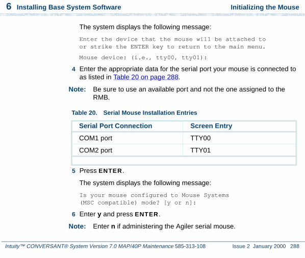
6 Installing Base System Software Initializing the Mouse
Intuity™ CONVERSANT® System Version 7.0 MAP/40P Maintenance 585-313-108 Issue 2 January 2000 288
The system displays the following message:
Enter the device that the mouse will be attached toor strike the ENTER key to return to the main menu.
Mouse device: (i.e., tty00, tty01):
4 Enter the appropriate data for the serial port your mouse is connected to as listed in Table 20 on page 288.
Note: Be sure to use an available port and not the one assigned to the RMB.
.
5 Press ENTER.
The system displays the following message:
Is your mouse configured to Mouse Systems (MSC compatible) mode? [y or n]:
6 Enter y and press ENTER.
Note: Enter n if administering the Agiler serial mouse.
Table 20. Serial Mouse Installation Entries
Serial Port Connection Screen Entry
COM1 port TTY00
COM2 port TTY01
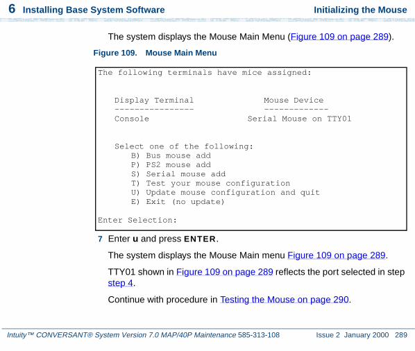
6 Installing Base System Software Initializing the Mouse
Intuity™ CONVERSANT® System Version 7.0 MAP/40P Maintenance 585-313-108 Issue 2 January 2000 289
The system displays the Mouse Main Menu (Figure 109 on page 289).
Figure 109. Mouse Main Menu
7 Enter u and press ENTER.
The system displays the Mouse Main menu Figure 109 on page 289.
TTY01 shown in Figure 109 on page 289 reflects the port selected in step step 4.
Continue with procedure in Testing the Mouse on page 290.
The following terminals have mice assigned:
Display Terminal Mouse Device---------------- -------------Console Serial Mouse on TTY01
Select one of the following:B) Bus mouse addP) PS2 mouse addS) Serial mouse addT) Test your mouse configurationU) Update mouse configuration and quitE) Exit (no update)
Enter Selection:

6 Installing Base System Software Testing the Mouse
Intuity™ CONVERSANT® System Version 7.0 MAP/40P Maintenance 585-313-108 Issue 2 January 2000 290
Testing the Mouse
To test the mouse, do the following:
1 Enter mouseadmin at the system prompt and press ENTER .
The system displays the Mouse Main Menu (Figure 109 on page 289).
2 Enter t and press ENTER.
The system displays the following message:
Please try using your mouse when the next screen appears.
Strike the ENTER key when ready:
3 Press ENTER.
The system displays the following message:
Press a mouse button to stop test.Test will be cancelled automatically in 15 seconds.
The system displays the Mouse Main Menu (Figure 109 on page 289).
4 Enter e and press ENTER.
You have now installed all the required software for your UnixWare operating system.

Intuity™ CONVERSANT® System Version 7.0 MAP/40P Maintenance 585-313-108 Issue 2 January 2000 291
7 Installing the IntuityCONVERSANT System Software
Overview
This chapter provides detailed installation procedures to reload the Intuity CONVERSANT system in the event of a disk failure. Use this chapter in conjunction with Appendix D, Disaster Recovery Checklists.

Intuity™ CONVERSANT® System Version 7.0 MAP/40P Maintenance 585-313-108 Issue 2 January 2000 292
7 Installing the Intuity CONVERSANT System Software Installing the Intuity CONVERSANT Base Software Set
Installing the Intuity CONVERSANT Base Software Set
The Intuity CONVERSANT base software set includes:
• Intuity CONVERSANT Utilities Package
• Intuity CONVERSANT Runtime Processing Package
• Intuity CONVERSANT Maintenance Package
• Intuity CONVERSANT Logger/Alerter Package
• Intuity AUDIX Logger Package
• Intuity CONVERSANT Base ORACLE RDBMS 7.3.2
• Intuity CONVERSANT ORACLE 7 Integration Package
• Intuity CONVERSANT Administration Screens Package
• Intuity CONVERSANT Transaction State Machine Package
• Intuity CONVERSANT Switch Utilities Package
• Intuity CONVERSANT License Modification Package
• Intuity CONVERSANT Platform CONVERSANT Tuning
All of the packages included in the Intuity CONVERSANT base software set are required for the operation of the Intuity CONVERSANT system. All of the packages are contained on one cartridge tape.

7 Installing the Intuity CONVERSANT System Software
Intuity™ CONVERSANT® System Version 7.0 MAP/40P Maintenance 585-313-108 Issue 2 January 2000 293
Installing the Intuity CONVERSANT Base Software Set
To install the Intuity CONVERSANT base software set, do the following:
! CAUTION:If you are using this procedure in conjunction with an upgrade, skip the first three steps and begin with step 4.
1 Log in as root.
2 Insert the cartridge tape labeled “Intuity Platform CVIS 7.0 Set 1 of 1” into the cartridge tape drive.
3 Enter pkgadd -d ctape1
The system displays the following message:
Insert a cartridge into Tape Drive 1.Type [go] when ready,
or [q] to quit: (default: go)
4 Press ENTER.
The system displays the following message:
Installation in progress. Do not remove the cartridge.
The following packages are available:
1. CVISset INTUITY CONVERSANT VIS V7 Set(i486)

Intuity™ CONVERSANT® System Version 7.0 MAP/40P Maintenance 585-313-108 Issue 2 January 2000 294
7 Installing the Intuity CONVERSANT System Software Installing the Intuity CONVERSANT Base Software Set
Select the package(s) you wish to process (or ‘all’ to process all packages). (default: all) [?,??,q]:
5 Press ENTER.
The system displays the following message:
PROCESSING:Set: INTUITY CONVERSANT VIS V7 Set (CVISset) from <ctape1>
INTUITY CONVERSANT VIS V7 Set(i486)Using </> as the package base directory.
Do you want to run the default set installation? (default: y)
6 Answer the questions in Table 21 on page 295 with a check mark for “yes” or “no.”

7 Installing the Intuity CONVERSANT System Software
Intuity™ CONVERSANT® System Version 7.0 MAP/40P Maintenance 585-313-108 Issue 2 January 2000 295
Installing the Intuity CONVERSANT Base Software Set
Table 21. Questions to Determine if the Default Installation is Appropriate
Number Question Yes No
1 Do you want to turn off daylight savings time?
2 Does your system have a remote maintenance circuit card?
Note: If you answer yes to this question, you must answer yes to Question 3.
3 Do you want to disable COM1?
4 Do you want to disable COM2?
5 Do you want to disable the parallel port?
6 Is Interrupt Level 4 being used by anything other than COM1?
7 Is Interrupt Level 3 being used by anything other than COM2?
8 Is Interrupt Level 7 being used by anything other than the parallel port?
9 Is your ORACLE database larger than 65 Mbyte

Intuity™ CONVERSANT® System Version 7.0 MAP/40P Maintenance 585-313-108 Issue 2 January 2000 296
7 Installing the Intuity CONVERSANT System Software Installing the Intuity CONVERSANT Base Software Set
7 If you answered no to all of the questions in Table 21 on page 295, you can use the default installation; enter y
If you answered yes to any of the questions in Table 21 on page 295, you can not use the default installation; complete the following step a through step p.
a Enter n
The system displays the following message:
Do you want the default installation for mtce? [y,n,?]
b If you answered no to Question 1 in Table 21 on page 295, enter y and skip to step d.
If you answered yes to Question 1 in Table 21 on page 295, enter n
The system displays the following message:
Is Daylight Savings Time ever used? [y,n,?]
c Enter n
The system displays the following message:
Do you want the default installation for vs? [y,n,?]
d If you answered no to all seven Questions 2, 3, 4, 5, 6, 7, and 8 in Table 21 on page 295, enter y and skip to step g.

7 Installing the Intuity CONVERSANT System Software
Intuity™ CONVERSANT® System Version 7.0 MAP/40P Maintenance 585-313-108 Issue 2 January 2000 297
Installing the Intuity CONVERSANT Base Software Set
If you answered yes to Question 2, 3, 4, 5, 6, 7, or 8 in Table 21 on page 295, enter n
The system displays the following message:
The first serial port uses interrupt level 4The second serial port uses interrupt level 3The parallel port uses interrupt level 7
If you wish to reclaim some of these interrupts for other devices, you may disable one of these serial ports. However, one serial port must be enabled.
For serial ports would you like to:1. Enable both2. Enable first, disable second3. Disable first, enable second
Please enter your selection:
e If you answered no to Questions 2, 3, 4, 6, and 7 in Table 21 on page 295, enter 1
If you answered no to Questions 2, 3, and 6 and yes for Question 4 or 7 in Table 21 on page 295, enter 2
If you answered yes to Question 2, 3, or 6 and no for Questions 4 and 7 in Table 21 on page 295, enter 3

Intuity™ CONVERSANT® System Version 7.0 MAP/40P Maintenance 585-313-108 Issue 2 January 2000 298
7 Installing the Intuity CONVERSANT System Software Installing the Intuity CONVERSANT Base Software Set
Note: If you would like to disable both serial ports, enter 3, complete the installation procedure, edit the /etc/conf/sdevice.d/asyc file, and reboot the system.
The system displays the following message:
For the parallel port (interrupt 7) would you like to:1. Enable the parallel port2. Disable the parallel port
f If you answered no for Questions 5 and 8 in Table 21 on page 295, enter 1
If you answered yes for Question 5 or 8 in Table 21 on page 295, enter 2
The system displays the following message:
Do you want the default installation for maint?
g Enter n
Note: There is no difference between the default installation and a custom installation of the maint system.
The system displays the following message:
Do you want the default installation for machlog? [y,n,?]
h If you answered no to Questions 2, 3, and 4 in Table 21 on page 295, enter y and skip to step j.

7 Installing the Intuity CONVERSANT System Software
Intuity™ CONVERSANT® System Version 7.0 MAP/40P Maintenance 585-313-108 Issue 2 January 2000 299
Installing the Intuity CONVERSANT Base Software Set
If you answered yes to Question 2, 3, or 4 in Table 21 on page 295, enter n
The system displays the following message:
The first serial port uses interrupt level 4The second serial port uses interrupt level 3
If you wish to reclaim some of these interrupts for other devices, you may have to free some of these ports. However, one serial port must be configured as the alarm port.
For serial ports would you like to:1. Enable first serial port (COM1) as alarm port2. Enable second serial port (COM2) as alarm port
Please enter your selection:
i If you answered no for Questions 2 and 3 and yes for Question 4 in Table 21 on page 295, enter 1
Note: If your system has a remote maintenance circuit card, make sure COM1 is disabled in the CMOS settings. See P5 200 MHz CPU Circuit Card in Chapter 2, Installing or Replacing Circuit Cards , for the procedure to edit the CMOS settings.
If you answered yes to Questions 2 and 3 and no for Question 4 in Table 21 on page 295, enter 1

Intuity™ CONVERSANT® System Version 7.0 MAP/40P Maintenance 585-313-108 Issue 2 January 2000 300
7 Installing the Intuity CONVERSANT System Software Installing the Intuity CONVERSANT Base Software Set
If you answered yes to Question 3 and no for Questions 2 and 4 in Table 21 on page 295, enter 2
The system displays the following message:
Serial port X has been configured as the alarm port.
j If you answered no for Question 9 in Table 21 on page 295, enter y and skip to step 8.
If you answered yes for Question 9 in Table 21 on page 295, enter n
The system displays the following message:
The default name for the database file is dbsA.dbf
Enter a new name or strike ENTER to accept the default.
k Press ENTER.
The system displays the following message:
The default name for the first redo log file is log1A.dbf
Enter a new name or strike ENTER to accept the default.
l Press ENTER.
The system displays the following message:
The default name for the second redo log file is log2A.dbf

7 Installing the Intuity CONVERSANT System Software
Intuity™ CONVERSANT® System Version 7.0 MAP/40P Maintenance 585-313-108 Issue 2 January 2000 301
Installing the Intuity CONVERSANT Base Software Set
Enter a new name or strike ENTER to accept the default.
m Press ENTER.
The system displays the following message:
How many blocks do you want in your database? [default: 132,000].
n Enter the number of blocks you want in your database.
! CAUTION:This number must be greater than 24,000.
The system displays the following message:
The default size for each of the redo log files is 800 [512 bytes] blocks.
How many blocks do you want in each of the redo log files? [default: 800].
o Enter the number of blocks you want in your redo log files.
The system displays the following message:
Do you want to install TSM? [y,n,?]
p Enter y

Intuity™ CONVERSANT® System Version 7.0 MAP/40P Maintenance 585-313-108 Issue 2 January 2000 302
7 Installing the Intuity CONVERSANT System Software Installing the Intuity CONVERSANT Base Software Set
The system displays the following message:
Lucent Technologies Inc.## Processing package information.## Processing system information.## Verifying disk space requirements.
Installing INTUITY CONVERSANT VIS V7.0 Set as <CVISset>
## Executing preinstall script.Executing the preinstall personality script for CVIStune.Enter password for oracle:New password:
! CAUTION:If you are using this procedure in conjunction with an upgrade, stop here and return to Intuity CONVERSANT System Version 7.0 Upgrade Procedures. Do not continue with step 8.
8 Type the new password.
9 Press ENTER.
The system displays the following message:
Re-enter new password:
10 Re-type the new password.
11 Press ENTER.

7 Installing the Intuity CONVERSANT System Software
Intuity™ CONVERSANT® System Version 7.0 MAP/40P Maintenance 585-313-108 Issue 2 January 2000 303
Installing the Intuity CONVERSANT Base Software Set
The system displays a series of messages. After approximately one hour the system displays the following message:
Processing of <INTUITY CONVERSANT VIS V7.0 Set> is completed.
Insert a cartridge into Tape Drive 1.
Type [go] when ready,or [q] to quit: (default: go)
12 Enter q
The system displays the following message:
***IMPORTANT NOTICE***If installation of all desired packages is complete, the machine should be rebooted in orderto ensure sane operation. Execute the shutdowncommand with the appropriate options and wait forthe "Console Login:" prompt.
13 Enter shutdown -i6 -g0 -y

Intuity™ CONVERSANT® System Version 7.0 MAP/40P Maintenance 585-313-108 Issue 2 January 2000 304
7 Installing the Intuity CONVERSANT System Software Installing the TCP/IP Packages
Installing the TCP/IP Packages
All of the UnixWare TCP/IP packages are installed during the installation of the operating system from the cartridge tape labeled “Intuity CONVERSANT VIS V7.0 UnixWare for Intuity 2.1.2.”
• Distributed File System Utilities
• Remote Procedure Calls Utilities
• Internet Utilities
Use the pkginfo command to view the list of packages on your system. If these packages are not installed on your system, install them now.
To install the TCP/IP packages, do the following:
1 Enter pkgadd -d ctape1
The system displays the following message:
Insert a cartridge into Tape Drive 1.Type [go] when ready,
or [q] to quit: (default: go)
2 Insert the cartridge tape labeled “Intuity CONVERSANT VIS V7.0 UnixWare for Intuity 2.1.2.”
3 Press ENTER.

7 Installing the Intuity CONVERSANT System Software
Intuity™ CONVERSANT® System Version 7.0 MAP/40P Maintenance 585-313-108 Issue 2 January 2000 305
Installing the TCP/IP Packages
The system displays a list of packages from which you must specify yes or no.
4 Enter yes for the following packages:
~ Distributed File System Utilities
~ Remote Procedure Calls Utilities
~ Internet Utilities
Enter no for all other packages.
5 Press ENTER.
The system displays the following message:
Insert a cartridge into Tape Drive 1.Type [go] when ready or [q] to quit: (default: go)
6 Enter q

Intuity™ CONVERSANT® System Version 7.0 MAP/40P Maintenance 585-313-108 Issue 2 January 2000 306
8 Installing the Optional FeatureSoftware
Overview
Note: All of the procedures in this chapter must be performed with root permission.
This chapter describes the procedures to install all the software that was not included on the application software cartridge tape. This software is called optional since it is not required for the basic system to function. The organization of this chapter is not to imply that you will necessarily install all of these packages nor will you install them in the order documented. Packages that are order-specific are identified as such.
This chapter also describes the general procedure for removing software packages.
The information in this chapter is necessary to reload the optional feature software on a computer that has experienced a disk failure.
Note: Be sure that you have run the Intuity CONVERSANT Hardware Resource Allocator and indicate all hardware that is or will be on your system. The data generated by the program is crucial in assuring that you respond correctly the prompts in this chapter.

Intuity™ CONVERSANT® System Version 7.0 MAP/40P Maintenance 585-313-108 Issue 2 January 2000 307
8 Installing the Optional Feature Software Installing Software Packages Using the Unix Management Screens
See Operating the Hardware Resource Allocator on page 468 in Appendix A, System Configuration, in your hardware installation book.
Installing Software Packages Using the Unix Management Screens
If your system has been equipped the Unix Management Screens Package, software can be loaded using the Intuity CONVERSANT system screens.
To load software a software package using the Intuity CONVERSANT system screens do the following:
1 Start at the Voice System Administration menu (Figure 110 on page 308).

Intuity™ CONVERSANT® System Version 7.0 MAP/40P Maintenance 585-313-108 Issue 2 January 2000 308
8 Installing the Optional Feature Software Installing Software Packages Using the Unix Management Screens
Figure 110. Voice System Administration Menu
2 Select:
The system displays the Software Install menu (Figure 111 on page 309).
>Software Install
> UNIX Management

Intuity™ CONVERSANT® System Version 7.0 MAP/40P Maintenance 585-313-108 Issue 2 January 2000 309
8 Installing the Optional Feature Software
Installing the Hardware Resource Allocator Package
Figure 111. Software Install Menu
3 Select the appropriate media.
4 Continue with the procedures for each package.
Installing the Hardware Resource Allocator Package
Note: You must install and run the Intuity CONVERSANT Hardware Resource Allocator before installing any of the Intuity CONVERSANT System Version 7.0 base or optional packages.
To install the Hardware Resource Allocator package, do the following:
1 If you are not already logged in as root, do so now.
2 Enter pkgadd -d diskette1
The system displays the following message:
Insert diskette into Floppy Drive 1.Type [go] when ready,
or [q] to quit: (default: go)

Intuity™ CONVERSANT® System Version 7.0 MAP/40P Maintenance 585-313-108 Issue 2 January 2000 310
8 Installing the Optional Feature Software
Installing the Hardware Resource Allocator Package
3 Insert the diskette labeled “Hardware Resource Allocator 1 of 1” into the diskette drive.
4 Press ENTER.
The system displays the following message:
Installation in progress -- do not remove the diskette.
The following packages are available: 1. config INTUITY Hardware Resource Allocator
(i486)
Select package(s) you wish to process (or ‘all’ to process all packages). (default: all) [?,??,q]:
5 Press ENTER.
The system displays the following message:
PROCESSING:Set: INTUITY Hardware Resource Allocator (config) from <diskette1>
INTUITY Hardware Resource Allocator(i486)Using </> as the package base directory.

Intuity™ CONVERSANT® System Version 7.0 MAP/40P Maintenance 585-313-108 Issue 2 January 2000 311
8 Installing the Optional Feature Software
Installing the Hardware Resource Allocator Package
The system displays several status messages and then the following message:
Installation of INTUITY Hardware Resource Allocator (config) was successful.
Insert diskette into Floppy Drive 1.Type [go] when ready,
or [q] to quit: (default: go)
6 Remove the diskette labeled “Hardware Resource Allocator 1 of 1” from the diskette drive.
7 Enter q
Run the Intuity CONVERSANT Hardware Resource Allocator to obtain a current configuration listing for your system. See Operating the Hardware Resource Allocator on page 468 in Appendix A, System Configuration.
! CAUTION:You must run the Intuity CONVERSANT Hardware Resource Allocator and obtain the output from it. The information is needed to install software packages to correctly set addresses for interrupts, I/O, etc.

Intuity™ CONVERSANT® System Version 7.0 MAP/40P Maintenance 585-313-108 Issue 2 January 2000 312
8 Installing the Optional Feature Software
Installing the Asynchronous Host Toolkit
Installing the Asynchronous Host Toolkit
To install the Asynchronous Host Toolkit package, do the following:
1 If you are not already logged in as root, do so now.
2 Enter pkgadd -d diskette1
The system displays the following message:
Insert diskette into Floppy Drive 1.Type [go] when ready,
or [q] to quit: (default: go)
3 Insert the diskette labeled “CGS Asynchronous Host Toolkit 1 of 1” into the diskette drive.
4 Press ENTER.
The system displays the following message:
Installation in progress -- do not remove the diskette.
The following packages are available: 1. asynchost INTUITY CSG Asynchronous Host Toolkit
(i486)
Select package(s) you wish to process (or ‘all’ to process all packages). (default: all) [?,??,q]:
5 Press ENTER.

Intuity™ CONVERSANT® System Version 7.0 MAP/40P Maintenance 585-313-108 Issue 2 January 2000 313
8 Installing the Optional Feature Software
Installing the Asynchronous Host Toolkit
The system displays the following message:
PROCESSING:Set: INTUITY CSG Asynchronous Host Toolkit (asynchost) from <diskette1>
INTUITY CSG Asynchronous Host Toolkit(i486)Using </> as the package base directory.Lucent Technologies Inc.Enter number of host lines to be configured, 1 or 2:
6 Enter the number of lines to be configured.
This is the number of lines your system will be using to communicate with the host.
~ If you entered 1, the system displays the following message:
Enter asynchronous request function number, 1 or 2:
Note: Entering 1 turns on the DIP for hostreq1 host line only. Entering 2 turns on the DIP for hostreq2 host line only
~ If you entered 2, the system displays the following message:
Enter asynchronous request function number, S or D:
Note: Entering S turns on both host DIPs and they will work independently of each other. Entering D will turn on both host DIPs and they will work in conjunction with each other.

Intuity™ CONVERSANT® System Version 7.0 MAP/40P Maintenance 585-313-108 Issue 2 January 2000 314
8 Installing the Optional Feature Software
Installing the Asynchronous Host Toolkit
7 Enter the request number function.
The system displays the following message:
Enter tty port for the single line (e.q., ttys02):
Note: The tty port number is assigned to the port on the asynchronous circuit card to which you are connecting. See Chapter 3, “Making Cable Connections,” in Intuity CONVERSANT System Version 7.0 New System Installation, 538-313-106.
You can also determine the available tty addresses by viewing the /dev file.
8 Enter the tty port number you will be using.
The system displays the following message:
Installation of INTUITY CGS Asynchronous Host Toolkit (asynchost) was successful.
Insert diskette into Floppy Drive 1.Type [go] when ready,
or [q] to quit: (default: go)
9 Remove the diskette labeled “CGS Asynchronous Host Toolkit 1 of 1” from the diskette drive.
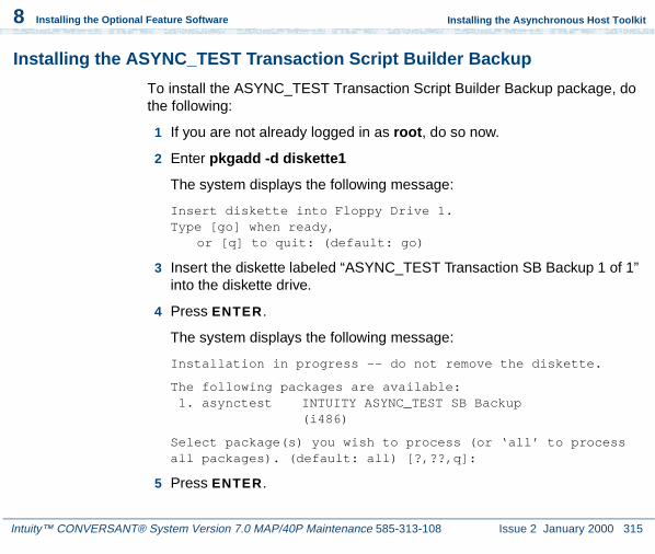
Intuity™ CONVERSANT® System Version 7.0 MAP/40P Maintenance 585-313-108 Issue 2 January 2000 315
8 Installing the Optional Feature Software
Installing the Asynchronous Host Toolkit
Installing the ASYNC_TEST Transaction Script Builder Backup
To install the ASYNC_TEST Transaction Script Builder Backup package, do the following:
1 If you are not already logged in as root, do so now.
2 Enter pkgadd -d diskette1
The system displays the following message:
Insert diskette into Floppy Drive 1.Type [go] when ready,
or [q] to quit: (default: go)
3 Insert the diskette labeled “ASYNC_TEST Transaction SB Backup 1 of 1” into the diskette drive.
4 Press ENTER.
The system displays the following message:
Installation in progress -- do not remove the diskette.
The following packages are available: 1. asynctest INTUITY ASYNC_TEST SB Backup
(i486)
Select package(s) you wish to process (or ‘all’ to process all packages). (default: all) [?,??,q]:
5 Press ENTER.

Intuity™ CONVERSANT® System Version 7.0 MAP/40P Maintenance 585-313-108 Issue 2 January 2000 316
8 Installing the Optional Feature Software
Installing the Asynchronous Host Toolkit
The system displays the following message:
PROCESSING:Set: INTUITY ASYNC_TEST SB Backup (asynctest) from <diskette1>
INTUITY ASYNC_TEST SB Backup(i486)Using </> as the package base directory.Lucent Technologies Inc.
The system displays several status messages and then the following message:
Installation of INTUITY ASYNC_TEST SB Backup (asynctest) was successful.
Insert diskette into Floppy Drive 1.Type [go] when ready,
or [q] to quit: (default: go)
6 Remove the diskette labeled “ASYNC_TEST Transaction SB Backup 1 of 1” from the diskette drive.

Intuity™ CONVERSANT® System Version 7.0 MAP/40P Maintenance 585-313-108 Issue 2 January 2000 317
8 Installing the Optional Feature Software
Installing the Asynchronous Host Toolkit
Installing the ASYNC_TEST Speech Script Builder Backup
To install the SYNC_TEST Speech Script Builder Backup package, do the following:
1 If you are not already logged in as root, do so now.
2 Enter pkgadd -d diskette1
The system displays the following message:
Insert diskette into Floppy Drive 1.Type [go] when ready,
or [q] to quit: (default: go)
3 Insert the diskette labeled “ASYNC_TEST Speech SB Backup 1 of 1” into the diskette drive.
4 Press ENTER.
The system displays the following message:
Installation in progress -- do not remove the diskette.
The following packages are available: 1. asynctest INTUITY ASYNC_TEST SB Backup
(i486)
Select package(s) you wish to process (or ‘all’ to process all packages). (default: all) [?,??,q]:
5 Press ENTER.

Intuity™ CONVERSANT® System Version 7.0 MAP/40P Maintenance 585-313-108 Issue 2 January 2000 318
8 Installing the Optional Feature Software
Installing the Asynchronous Host Toolkit
The system displays the following message:
PROCESSING:Set: INTUITY ASYNC_TEST SB Backup (asynctest) from <diskette1>
INTUITY ASYNC_TEST SB Backup(i486)Using </> as the package base directory.Lucent Technologies Inc.
The system displays several status messages and then the following message:
Installation of INTUITY ASYNC_TEST SB Backup (asynctest) was successful.
Insert diskette into Floppy Drive 1.Type [go] when ready,
or [q] to quit: (default: go)
6 Enter q
7 Remove the diskette labeled “ASYNC_TEST Speech SB Backup 1 of 1” from the diskette drive.

Intuity™ CONVERSANT® System Version 7.0 MAP/40P Maintenance 585-313-108 Issue 2 January 2000 319
8 Installing the Optional Feature Software
Installing the Adjunct/Switch Application Interface Packages
Installing the Adjunct/Switch Application Interface Packages
Procedures to install the ASAI packages must be performed in the following order:
1 Installing the CALLVISOR PC ISDN Package on page 319
2 Installing the CALLVISOR PC LAN Gateway Package on page 322
3 Installing the CALLVISOR PC ASAI Package on page 324
Installing the CALLVISOR PC ISDN Package
To install the CALLVISOR PC ISDN package, do the following:
1 If you are not already logged in as root, do so now.
2 Enter pkgadd -d diskette1
The system displays the following message:
Insert diskette into Floppy Drive 1.Type [go] when ready,
or [q] to quit: (default: go)
3 Insert the diskette labeled “AT&T CALLVISOR PC ISDN Package 1 of 1” into the diskette drive.

Intuity™ CONVERSANT® System Version 7.0 MAP/40P Maintenance 585-313-108 Issue 2 January 2000 320
8 Installing the Optional Feature Software
Installing the Adjunct/Switch Application Interface Packages
4 Press ENTER.
The system displays the following message:
Installation in progress -- do not remove the diskette.
The following packages are available: 1. cvisdn AT&T CALLVISOR PC ISDN Package
(i486)
Select package(s) you wish to process (or ‘all’ to process all packages). (default: all) [?,??,q]:
5 Press ENTER.
The system displays the following message:
PROCESSING:Set: AT&T CALLVISOR PC ISDN Package (cvisdn) from <diskette1>
INTUITY CALLVISOR PC ISDN Package(i486)Using </> as the package base directory.Lucent Technologies Inc.
Enter the number of IPCI boards installed on this machine. (default: 1) [1-4,?]

Intuity™ CONVERSANT® System Version 7.0 MAP/40P Maintenance 585-313-108 Issue 2 January 2000 321
8 Installing the Optional Feature Software
Installing the Adjunct/Switch Application Interface Packages
6 Enter 0
The system displays the following message:
Enter the desired version. (default: 1) [?]
7 Enter the desired version for the PC/ISDN (IPCI) circuit cards installed in your system
Note: Enter 1 if your system is connected to a G3V3 switch.Enter 2 if your system is connected to a G3V4 switch.
The system displays the following message:
Enter for higher version operation. (default: 1) [0-1,?]
8 Press ENTER.
The system displays the following message:
Enter for lower version operation. (default: 1) [0-1,?]
9 Press ENTER.
The system displays several messages followed by the following message:
The UNIX Operating System kernel will be rebuilt to include your configuration changes during the next system reboot.
Remove the diskette from the drive.

Intuity™ CONVERSANT® System Version 7.0 MAP/40P Maintenance 585-313-108 Issue 2 January 2000 322
8 Installing the Optional Feature Software
Installing the Adjunct/Switch Application Interface Packages
To reboot the system, execute the command:shutdown -i6 -y -g0
10 Remove the diskette labeled “AT&T CALLVISOR PC ISDN Package 1 of 1” from the diskette drive.
11 Continue with the procedure in Installing the CALLVISOR PC LAN Gateway Package on page 322.
Installing the CALLVISOR PC LAN Gateway Package
To install the CALLVISOR PC LAN Gateway package, do the following:
1 Enter pkgadd -d diskette1
The system displays the following message:
Insert diskette into Floppy Drive 1.Type [go] when ready,
or [q] to quit: (default: go)
2 Insert the diskette labeled “AT&T CALLVISOR PC LAN Gateway Package 1 of 1” into the diskette drive.
3 Press ENTER.
The system displays the following message:
Installation in progress -- do not remove the diskette.

Intuity™ CONVERSANT® System Version 7.0 MAP/40P Maintenance 585-313-108 Issue 2 January 2000 323
8 Installing the Optional Feature Software
Installing the Adjunct/Switch Application Interface Packages
The following packages are available: 1. cvesai AT&T CALLVISOR PC LAN Gateway Package
(i486)
Select package(s) you wish to process (or ‘all’ to process all packages). (default: all) [?,??,q]:
4 Press ENTER.
The system displays the following message:
PROCESSING:Set: AT&T CALLVISOR PC LAN Gateway Package (cvesai) from <diskette1>
AT&T CALLVISOR PC LAN Gateway Package(i486)Using </> as the package base directory.Lucent Technologies Inc.
This machine currently has X BRA links administeredThere are X links available for use as LAN Gateway links.
Enter the number of LAN links to be installed (<=X):
5 Enter the number of LAN links used by your system.
Note: The Intuity CONVERSANT system requires one LAN link. If your system needs additional LAN connections for other software, establish the links now.

Intuity™ CONVERSANT® System Version 7.0 MAP/40P Maintenance 585-313-108 Issue 2 January 2000 324
8 Installing the Optional Feature Software
Installing the Adjunct/Switch Application Interface Packages
The system displays the following message:
Enter the destination for LAN link 1 [Definity]:
6 Enter your system’s switch destination.
The UNIX Operating System kernel will be rebuilt to include your configuration changes during the next system reboot.
Installation of the AT&T CALLVISOR PC LAN Gateway Package (cvesai) was successful.
***IMPORTANT NOTICE***If installation of all desired packages is complete, the machine should be rebooted to ensuresane operation. Execute the shutdown command with appropriate options and wait for the "Console Login:" prompt.
7 Remove the diskette labeled “AT&T CALLVISOR PC LAN Gateway Package 1 of 1” from the diskette drive.
8 Continue with the procedure in Installing the CALLVISOR PC ASAI Package on page 324.
Installing the CALLVISOR PC ASAI Package
To install the CALLVISOR PC ASAI package, do the following:
1 Enter pkgadd -d diskette1

Intuity™ CONVERSANT® System Version 7.0 MAP/40P Maintenance 585-313-108 Issue 2 January 2000 325
8 Installing the Optional Feature Software
Installing the Adjunct/Switch Application Interface Packages
The system displays the following message:
Insert diskette into Floppy Drive 1.Type [go] when ready,
or [q] to quit: (default: go)
2 Insert the diskette labeled “CALLVISOR PC ASAI Package 1 of 1” into the diskette drive.
3 Press ENTER.
The system displays the following message:
Installation in progress -- do not remove the diskette.
The following packages are available: 1. cvasai AT&T CALLVISOR PC ASAI Package
(i486)
Select package(s) you wish to process (or ‘all’ to process all packages). (default: all) [?,??,q]:
4 Press ENTER.
The system displays the following message:
Configuring cvasai for X ASAI Node(s)
PROCESSING:Set: AT&T CALLVISOR PC ASAI Package (cvasai) from <diskette1>

Intuity™ CONVERSANT® System Version 7.0 MAP/40P Maintenance 585-313-108 Issue 2 January 2000 326
8 Installing the Optional Feature Software
Installing the Adjunct/Switch Application Interface Packages
AT&T CALLVISOR PC ASAI Package(i486)Using </> as the package base directory.Lucent Technologies Inc.
Enter the number of ASAI Nodes.(default: 1) [1-4,?]
5 Enter the number of ASAI nodes on your system
The system displays several status messages and then the following message:
The UNIX Operating System kernel will be rebuilt to include you configuration changes during the next system reboot.
Remove the diskette from the disk drive.
To reboot the system, execute the command:shutdown -i6 -y -g0
To power down the system, execute the command:shutdown -i0 -y -g0
***IMPORTANT NOTICE***If installation of all desired packages is complete, the machine should be rebooted to ensuresane operation. Execute the shutdown command with appropriate options and wait for the "Console Login:" prompt.
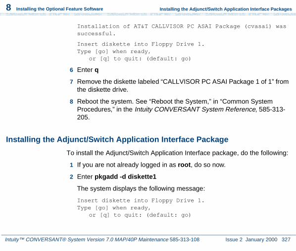
Intuity™ CONVERSANT® System Version 7.0 MAP/40P Maintenance 585-313-108 Issue 2 January 2000 327
8 Installing the Optional Feature Software
Installing the Adjunct/Switch Application Interface Packages
Installation of AT&T CALLVISOR PC ASAI Package (cvasai) was successful.
Insert diskette into Floppy Drive 1.Type [go] when ready,
or [q] to quit: (default: go)
6 Enter q
7 Remove the diskette labeled “CALLVISOR PC ASAI Package 1 of 1” from the diskette drive.
8 Reboot the system. See “Reboot the System,” in “Common System Procedures,” in the Intuity CONVERSANT System Reference, 585-313-205.
Installing the Adjunct/Switch Application Interface Package
To install the Adjunct/Switch Application Interface package, do the following:
1 If you are not already logged in as root, do so now.
2 Enter pkgadd -d diskette1
The system displays the following message:
Insert diskette into Floppy Drive 1.Type [go] when ready,
or [q] to quit: (default: go)

Intuity™ CONVERSANT® System Version 7.0 MAP/40P Maintenance 585-313-108 Issue 2 January 2000 328
8 Installing the Optional Feature Software
Installing the Adjunct/Switch Application Interface Packages
3 Insert the diskette labeled “Adjunct/Switch Application Interface Package 1 of 3” into the diskette drive.
4 Press ENTER.
The system displays the following message:
Installation in progress -- do not remove the diskette.
The following packages are available: 1. asai INTUITY Adjunct/Switch Application
Interface Package (i486)
Select package(s) you wish to process (or ‘all’ to process all packages). (default: all) [?,??,q]:
5 Press ENTER.
The system displays the following message:
PROCESSING:Set: INTUITY Adjunct/Switch Application Interface Package (asai) from <diskette1>
INTUITY Adjunct/Switch Application Interface Package(i486)Using </> as the package base directory.Lucent Technologies Inc.

Intuity™ CONVERSANT® System Version 7.0 MAP/40P Maintenance 585-313-108 Issue 2 January 2000 329
8 Installing the Optional Feature Software
Installing the Adjunct/Switch Application Interface Packages
The system displays several status messages and then the following message:
READY TO PROCESS:Package: INTUITY Adjunct/Switch Application
Interface Package (asai) diskette 2 of 3
Insert diskette 2 of 3 into Floppy Drive 1.Type [go] when ready,
or [q] to quit: (default: go)
6 Remove the diskette labeled “Adjunct/Switch Application Interface Package 1 of 3” from the diskette drive.
7 Insert the diskette labeled “Adjunct/Switch Application Interface Package 2 of 3” into the diskette drive.
8 Press ENTER.
The system displays several status messages and then the following message:
READY TO PROCESS:Package: INTUITY Adjunct/Switch Application
Interface Package (asai) diskette 3 of 3
Insert diskette 3 of 3 into Floppy Drive 1.Type [go] when ready,
or [q] to quit: (default: go)

Intuity™ CONVERSANT® System Version 7.0 MAP/40P Maintenance 585-313-108 Issue 2 January 2000 330
8 Installing the Optional Feature Software
Installing the Adjunct/Switch Application Interface Packages
9 Remove the diskette labeled “Adjunct/Switch Application Interface Package 2 of 3” from the diskette drive.
10 Insert the diskette labeled “Adjunct/Switch Application Interface Package 3 of 3” into the diskette drive.
11 Press ENTER.
The system displays several status messages and then the following message:
The UNIX Operating System kernel will be rebuilt to include your configuration changes during the next system reboot.
Installation of Adjunct/Switch Application Interface Package (asai) was successful.
Insert diskette into Floppy Drive 1.Type [go] when ready,
or [q] to quit: (default: go)
12 Enter q
13 Remove the diskette labeled “Adjunct/Switch Application Interface Package 3 of 3” from the diskette drive.

Intuity™ CONVERSANT® System Version 7.0 MAP/40P Maintenance 585-313-108 Issue 2 January 2000 331
8 Installing the Optional Feature Software
Installing the Analog Switch Interface Package
14 Reboot the system. See “Reboot the System,” in “Common System Procedures,” in the Intuity CONVERSANT System Reference, 585-313-205.
For more information on this feature package, see Intuity CONVERSANT Version 7.0 Communication Development, 585-313-202.
Installing the Analog Switch Interface Package
To install the Analog Switch Interface package, do the following:
1 If you are not already logged in as root, do so now.
2 Enter pkgadd -d diskette1
The system displays the following message:
Insert diskette into Floppy Drive 1.Type [go] when ready,
or [q] to quit: (default: go)
3 Insert the diskette labeled “Analog Switch Interface - (country) 1 of 1” into the diskette drive.
4 Press ENTER.
The system displays the following message:
Installation in progress -- do not remove the diskette.

Intuity™ CONVERSANT® System Version 7.0 MAP/40P Maintenance 585-313-108 Issue 2 January 2000 332
8 Installing the Optional Feature Software
Installing the Analog Switch Interface Package
The following packages are available: 1. usswtch INTUITY Analog Switch Interface Package
- US(i486)
Select package(s) you wish to process (or ‘all’ to process all packages). (default: all) [?,??,q]:
Note: The analog switch interface package used in this example is for the United States (US). The name will change depending on the country chosen.
5 Press ENTER.
The system displays the following message:
PROCESSING:
Set: INTUITY Analog Switch Interface Package - US (usswtch)
from <diskette1>
INTUITY Analog Switch Interface Package - US(i486)Using </> as the package base directory.Lucent Technologies Inc.
The system displays several status messages and then the following message:
Installation of INTUITY Analog Switch Interface Package - US (usswtch) was successful.

Intuity™ CONVERSANT® System Version 7.0 MAP/40P Maintenance 585-313-108 Issue 2 January 2000 333
8 Installing the Optional Feature Software
Installing the Backup/Restore Utility
Insert diskette into Floppy Drive 1.Type [go] when ready,
or [q] to quit: (default: go)
6 Enter q
7 Remove the diskette labeled “Analog Switch Interface - (country) 1 of 1” from the diskette drive.
Installing the Backup/Restore Utility
To install the Backup/Restore Utility, do the following:
1 At the UNIX prompt, enter pkgadd -d diskette1
The system displays the following message:
Insert diskette into Floppy Drive 1.Type [go] when ready,
or [q] to quit: (default: go)
2 Insert the diskette labeled “Backup/Restore Utility 1 of 1” into the diskette drive.
3 Press ENTER.
The system displays the following message:
Installation in progress -- do not remove the diskette.
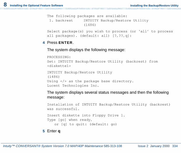
Intuity™ CONVERSANT® System Version 7.0 MAP/40P Maintenance 585-313-108 Issue 2 January 2000 334
8 Installing the Optional Feature Software
Installing the Backup/Restore Utility
The following packages are available: 1. backrest INTUITY Backup/Restore Utility
(i486)
Select package(s) you wish to process (or ‘all’ to process all packages). (default: all) [?,??,q]:
4 Press ENTER.
The system displays the following message:
PROCESSING:Set: INTUITY Backup/Restore Utility (backrest) from <diskette1>
INTUITY Backup/Restore Utility(i486)Using </> as the package base directory.Lucent Technologies Inc.
The system displays several status messages and then the following message:
Installation of INTUITY Backup/Restore Utility (backrest) was successful.
Insert diskette into Floppy Drive 1.Type [go] when ready,
or [q] to quit: (default: go)
5 Enter q

Intuity™ CONVERSANT® System Version 7.0 MAP/40P Maintenance 585-313-108 Issue 2 January 2000 335
8 Installing the Optional Feature Software
Installing the Call Bridge Application Package
The system displays the UNIX prompt.
6 Make sure that the light on the diskette drive is off and remove the diskette.
For more information on this feature package, see “Back Up the System,” in “Common System Procedures,” in the Intuity CONVERSANT System Reference, 585-313-205.
Installing the Call Bridge Application Package
To install the Call Bridge Application package, do the following:
1 If you are not already logged in as root, do so now.
2 Enter pkgadd -d diskette1
The system displays the following message:
Insert diskette into Floppy Drive 1.Type [go] when ready,
or [q] to quit: (default: go)
3 Insert the diskette labeled “Call Bridge Application Package 1 of 1” into the diskette drive.
4 Press ENTER.

Intuity™ CONVERSANT® System Version 7.0 MAP/40P Maintenance 585-313-108 Issue 2 January 2000 336
8 Installing the Optional Feature Software
Installing the Call Bridge Application Package
The system displays the following message:
Installation in progress -- do not remove the diskette.
The following packages are available: 1. xferdip INTUITY Call Bridge Application Package
(i486)
Select package(s) you wish to process (or ‘all’ to process all packages). (default: all) [?,??,q]:
5 Press ENTER.
The system displays the following message:
PROCESSING:Set: INTUITY Call Bridge Application Package (xferdip) from <diskette1>
INTUITY Call Bridge Application Package(i486)Using </> as the package base directory.Lucent Technologies Inc.
After the installation, do you wish to activate bridging capability? (y/n)
6 Enter y

Intuity™ CONVERSANT® System Version 7.0 MAP/40P Maintenance 585-313-108 Issue 2 January 2000 337
8 Installing the Optional Feature Software
Installing the Call Classification Analysis Package
The system displays several status messages and then the following message:
Installation of INTUITY Call Bridge Application Package (xferdip) was successful.
Insert diskette into Floppy Drive 1.Type [go] when ready,
or [q] to quit: (default: go)
7 Enter q
8 Remove the diskette labeled “Call Bridge Application Package 1 of 1” from the diskette drive.
Installing the Call Classification Analysis Package
Note: If you are installing the package and feature_tst is already installed on your system (as in assisted upgrades), once you have finished installing all other desired, you must remove feature_tst and reinstall it in order to select the CCA test.
To install the Call Classification Analysis package, do the following:
1 Make sure the ASP driver has been installed by entering pkginfo |pg

Intuity™ CONVERSANT® System Version 7.0 MAP/40P Maintenance 585-313-108 Issue 2 January 2000 338
8 Installing the Optional Feature Software
Installing the Call Classification Analysis Package
If the ASP driver has been installed there will be a line similar to the following:
intuity asp INTUITY ASP Driver Package
Continue with step 2.
If the ASP driver has not been installed, see Speech and Signal Processor (AYC43) Circuit Card on page 37, in Chapter 2, Installing or Replacing Circuit Cards , for the procedure to load the driver.
2 At the UNIX prompt, enter pkgadd -d diskette1
The system displays the following message:
Insert diskette into Floppy Drive 1.Type [go] when ready,
or [q] to quit: (default: go)
3 Insert the diskette labeled “Call Classification Analysis Package 1 of 1” into the diskette drive.
4 Press ENTER.
The system displays the following message:
Installation in progress -- do not remove the diskette.
The following packages are available: 1. cca INTUITY Call Classification Analysis
Package (i486)

Intuity™ CONVERSANT® System Version 7.0 MAP/40P Maintenance 585-313-108 Issue 2 January 2000 339
8 Installing the Optional Feature Software
Installing the Call Classification Analysis Package
Select package(s) you wish to process (or ‘all’ to process all packages). (default: all) [?,??,q]:
5 Press ENTER.
The system displays the following message:
PROCESSING:Set: INTUITY Call Classification Analysis Package (cca) from <diskette1>
INTUITY Call Classification Analysis Package(i486)Using </> as the package base directory.Lucent Technologies Inc.
The system displays several status messages and then the following message:
Installation of INTUITY Call Classification Analysis Package (cca) was successful.
Insert diskette into Floppy Drive 1.Type [go] when ready,
or [q] to quit: (default: go)
6 Enter q
The system displays the UNIX prompt.
7 Make sure that the light on the diskette drive is off and remove the diskette.

Intuity™ CONVERSANT® System Version 7.0 MAP/40P Maintenance 585-313-108 Issue 2 January 2000 340
8 Installing the Optional Feature Software
Installing the Data Collection Toolkit
For more information on this feature package, see Intuity CONVERSANT Version 7.0 Application Development with Script Builder, 585-313-206, and Intuity CONVERSANT Version 7.0 Communication Development, 585-313-202.
Installing the Data Collection Toolkit
To install the Data Collection Toolkit package, do the following:
1 If you are not already logged in as root, do so now.
2 Enter pkgadd -d diskette1
The system displays the following message:
Insert diskette into Floppy Drive 1.Type [go] when ready,
or [q] to quit: (default: go)
3 Insert the diskette labeled “Data Collection Toolkit 1 of 3” into the diskette drive.
4 Press ENTER.
The system displays the following message:
Installation in progress -- do not remove the diskette.

Intuity™ CONVERSANT® System Version 7.0 MAP/40P Maintenance 585-313-108 Issue 2 January 2000 341
8 Installing the Optional Feature Software
Installing the Data Collection Toolkit
The following packages are available: 1. dctoolkit INTUITY Data Collection Toolkit
(i486)
Select package(s) you wish to process (or ‘all’ to process all packages). (default: all) [?,??,q]:
5 Press ENTER.
The system displays the following message:
PROCESSING:Set: INTUITY Data Collection Toolkit (dctoolkit) from <diskette1>
INTUITY Data Collection Toolkit(i486)Using </> as the package base directory.Lucent Technologies Inc.
READY TO PROCESS:Package: INTUITY Data Collection Toolkit
(dctoolkit) diskette 2 of 3
Insert diskette 2 of 3 into Floppy Drive 1.Type [go] when ready,
or [q] to quit: (default: go)
6 Remove the diskette labeled “Data Collection Toolkit 1 of 3” from the diskette drive.

Intuity™ CONVERSANT® System Version 7.0 MAP/40P Maintenance 585-313-108 Issue 2 January 2000 342
8 Installing the Optional Feature Software
Installing the Data Collection Toolkit
7 Insert the diskette labeled “Data Collection Toolkit 2 of 3” into the diskette drive.
8 Press ENTER.
The system displays the following message:
READY TO PROCESS:Package: INTUITY Data Collection Toolkit
(dctoolkit) diskette 3 of 3
Insert diskette 3 of 3 into Floppy Drive 1.Type [go] when ready,
or [q] to quit: (default: go)
9 Remove the diskette labeled “Data Collection Toolkit 2 of 3” from the diskette drive.
10 Insert the diskette labeled “Data Collection Toolkit 3 of 3” into the diskette drive.
11 Press ENTER.
The system displays several status messages and then the following message:
Installation of INTUITY Data Collection Toolkit (dctoolkit) was successful.

Intuity™ CONVERSANT® System Version 7.0 MAP/40P Maintenance 585-313-108 Issue 2 January 2000 343
8 Installing the Optional Feature Software
Installing the Dial Pulse Recognition Package
Insert diskette into Floppy Drive 1.Type [go] when ready,
or [q] to quit: (default: go)
12 Enter q
13 Remove the diskette labeled “Data Collection Toolkit 3 of 3” from the diskette drive.
Installing the Dial Pulse Recognition Package
To install the Dial Pulse Recognition package, do the following:
1 If you are not already logged in as root, do so now.
2 Enter pkgadd -d diskette1
The system displays the following message:
Insert diskette into Floppy Drive 1.Type [go] when ready,
or [q] to quit: (default: go)
3 Insert the diskette labeled “Dial Pulse Recognition 1 of 1” into the diskette drive.
4 Press ENTER.

Intuity™ CONVERSANT® System Version 7.0 MAP/40P Maintenance 585-313-108 Issue 2 January 2000 344
8 Installing the Optional Feature Software
Installing the Dial Pulse Recognition Package
The system displays the following message:
Installation in progress -- do not remove the diskette.
The following packages are available: 1. dpr INTUITY Dial-Pulse Recognition Package
(i486)
Select package(s) you wish to process (or ‘all’ to process all packages). (default: all) [?,??,q]:
5 Press ENTER.
The system displays the following message:
PROCESSING:Set: INTUITY Dial-Pulse Recognition Package (dpr) from <diskette1>
INTUITY Dial-Pulse Recognition Package(i486)Using </> as the package base directory.Lucent Technologies Inc.
The system displays several status messages and then the following message:
Installation of INTUITY Dial-Pulse Recognition Package (dpr) was successful.

Intuity™ CONVERSANT® System Version 7.0 MAP/40P Maintenance 585-313-108 Issue 2 January 2000 345
8 Installing the Optional Feature Software
Installing the Enhanced Basic Speech Package
Insert diskette into Floppy Drive 1.Type [go] when ready,
or [q] to quit: (default: go)
6 Enter q
7 Remove the diskette labeled “Dial Pulse Recognition 1 of 1” from the diskette drive.
Installing the Enhanced Basic Speech Package
To install the Enhanced Basic Speech package, do the following:
1 If you are not already logged in as root, do so now.
2 Enter pkgadd -d diskette1
The system displays the following message:
Insert diskette into Floppy Drive 1.Type [go] when ready,
or [q] to quit: (default: go)
3 Insert the diskette labeled “Enhanced Basic Speech Package - Language 1 of 1” into the diskette drive.
4 Press ENTER.

Intuity™ CONVERSANT® System Version 7.0 MAP/40P Maintenance 585-313-108 Issue 2 January 2000 346
8 Installing the Optional Feature Software
Installing the Enhanced Basic Speech Package
The system displays the following message:
Installation in progress -- do not remove the diskette.
The following packages are available: 1. ebspchUS Enhanced Basic Speech - US English -
Female(i486)
Select package(s) you wish to process (or ‘all’ to process all packages). (default: all) [?,??,q]:
5 Press ENTER.
The system displays the following message:
PROCESSING:Set: Enhanced Basic Speech - US English - Female (ebspchUS) from <diskette1>
INTUITY Enhanced Basic Speech - US English - Female(i486)Using </> as the package base directory.Lucent Technologies Inc.
Installation of Enhanced Basic Speech - US English - Female (ebspchUS) was successful.
Insert diskette into Floppy Drive 1.Type [go] when ready,
or [q] to quit: (default: go)

Intuity™ CONVERSANT® System Version 7.0 MAP/40P Maintenance 585-313-108 Issue 2 January 2000 347
8 Installing the Optional Feature Software
Installing the FlexWord Speech Recognition Package
6 Enter q
7 Remove the diskette labeled “Enhanced Basic Speech Package - Language 1 of 1” from the diskette drive.
8 Reboot the system. See “Reboot the System,” in “Common System Procedures,” in the Intuity CONVERSANT System Reference, 585-313-205.
Installing the FlexWord Speech Recognition Package
Procedures to install the FlexWord Speech Recognition Package must be performed in the following order:
1 Installing the ASP Driver on page 347
2 Installing FlexWord Recognition - Base on page 348
3 Installing FlexWord Recognition - U.S. English on page 350
Installing the ASP Driver
See Speech and Signal Processor (AYC43) Circuit Card on page 37 in Chapter 2, Installing or Replacing Circuit Cards , for the procedure.
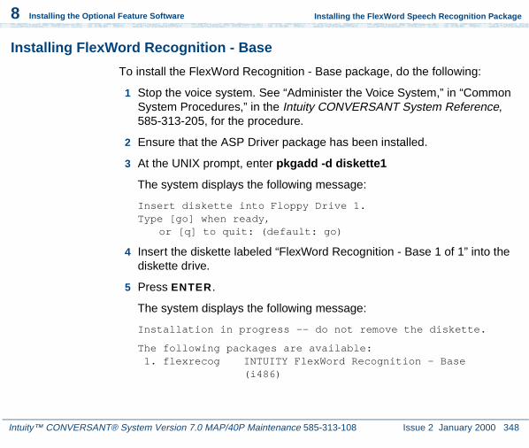
Intuity™ CONVERSANT® System Version 7.0 MAP/40P Maintenance 585-313-108 Issue 2 January 2000 348
8 Installing the Optional Feature Software
Installing the FlexWord Speech Recognition Package
Installing FlexWord Recognition - Base
To install the FlexWord Recognition - Base package, do the following:
1 Stop the voice system. See “Administer the Voice System,” in “Common System Procedures,” in the Intuity CONVERSANT System Reference, 585-313-205, for the procedure.
2 Ensure that the ASP Driver package has been installed.
3 At the UNIX prompt, enter pkgadd -d diskette1
The system displays the following message:
Insert diskette into Floppy Drive 1.Type [go] when ready,
or [q] to quit: (default: go)
4 Insert the diskette labeled “FlexWord Recognition - Base 1 of 1” into the diskette drive.
5 Press ENTER.
The system displays the following message:
Installation in progress -- do not remove the diskette.
The following packages are available: 1. flexrecog INTUITY FlexWord Recognition - Base
(i486)

Intuity™ CONVERSANT® System Version 7.0 MAP/40P Maintenance 585-313-108 Issue 2 January 2000 349
8 Installing the Optional Feature Software
Installing the FlexWord Speech Recognition Package
Select package(s) you wish to process (or ‘all’ to process all packages). (default: all) [?,??,q]:
Note: If you did not stop the voice system, the system displays the following message at this point:
The voice system is currently running and must be
stopped in order to install this package.
Is it ok to STOP the voice system? [y/n]
Enter y
6 Press ENTER.
The system displays the following message:
PROCESSING:Set: INTUITY FlexWord Recognition - Base (flexrecog) from <diskette1>
INTUITY FlexWord Recognition - Base(i486)Using </> as the package base directory.
The system displays several status messages and then the following message:
Installation of INTUITY FlexWord Recognition - Base (flexrecog) was successful.
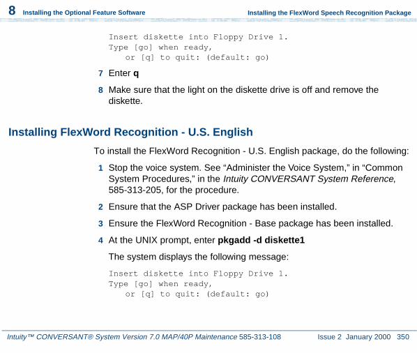
Intuity™ CONVERSANT® System Version 7.0 MAP/40P Maintenance 585-313-108 Issue 2 January 2000 350
8 Installing the Optional Feature Software
Installing the FlexWord Speech Recognition Package
Insert diskette into Floppy Drive 1.Type [go] when ready,
or [q] to quit: (default: go)
7 Enter q
8 Make sure that the light on the diskette drive is off and remove the diskette.
Installing FlexWord Recognition - U.S. English
To install the FlexWord Recognition - U.S. English package, do the following:
1 Stop the voice system. See “Administer the Voice System,” in “Common System Procedures,” in the Intuity CONVERSANT System Reference, 585-313-205, for the procedure.
2 Ensure that the ASP Driver package has been installed.
3 Ensure the FlexWord Recognition - Base package has been installed.
4 At the UNIX prompt, enter pkgadd -d diskette1
The system displays the following message:
Insert diskette into Floppy Drive 1.Type [go] when ready,
or [q] to quit: (default: go)

Intuity™ CONVERSANT® System Version 7.0 MAP/40P Maintenance 585-313-108 Issue 2 January 2000 351
8 Installing the Optional Feature Software
Installing the FlexWord Speech Recognition Package
5 Insert the diskette labeled “FlexWord Recognition - US English 1 of 5” into the diskette drive.
6 Press ENTER.
The system displays the following message:
Installation in progress -- do not remove the diskette.
The following packages are available: 1. usflex INTUITY FlexWord Recognition - US
English (i486)
Select package(s) you wish to process (or ‘all’ to process all packages). (default: all) [?,??,q]:
Note: If you did not stop the voice system, the system displays the following message at this point:
The voice system is currently running and must be
stopped in order to install this package.
Is it ok to STOP the voice system? [y/n]
Enter y
7 Press ENTER.

Intuity™ CONVERSANT® System Version 7.0 MAP/40P Maintenance 585-313-108 Issue 2 January 2000 352
8 Installing the Optional Feature Software
Installing the FlexWord Speech Recognition Package
The system displays the following message:
PROCESSING:Set: INTUITY FlexWord Recognition - US English (usflex) from <diskette1>
INTUITY FlexWord Recognition - US English(i486)Using </> as the package base directory.
READY TO PROCESS:Package: INTUITY FlexWord Recognition - US English
(usflex) diskette 2 of 5
Insert diskette 2 of 5 into Floppy Drive 1.Type [go] when ready,
or [q] to quit: (default: go)
8 Remove the diskette labeled “FlexWord Recognition - US English 1 of 5” from the diskette drive.
9 Insert the diskette labeled “FlexWord Recognition - US English 2 of 5” into the diskette drive.
10 Press ENTER.
The system displays the following message:
READY TO PROCESS:Package: INTUITY FlexWord Recognition - US English
(usflex) diskette 3 of 5

Intuity™ CONVERSANT® System Version 7.0 MAP/40P Maintenance 585-313-108 Issue 2 January 2000 353
8 Installing the Optional Feature Software
Installing the FlexWord Speech Recognition Package
Insert diskette 3 of 5 into Floppy Drive 1.Type [go] when ready,
or [q] to quit: (default: go)
11 Remove the diskette labeled “FlexWord Recognition - US English 2 of 5” from the diskette drive.
12 Insert the diskette labeled “FlexWord Recognition - US English 3 of 5” into the diskette drive.
13 Press ENTER.
The system displays the following message:
READY TO PROCESS:Package: INTUITY FlexWord Recognition - US English
(usflex) diskette 4 of 5
Insert diskette 4 of 5 into Floppy Drive 1.Type [go] when ready,
or [q] to quit: (default: go)
14 Remove the diskette labeled “FlexWord Recognition - US English 3 of 5” from the diskette drive.
15 Insert the diskette labeled “FlexWord Recognition - US English 4 of 5” into the diskette drive.
16 Press ENTER.

Intuity™ CONVERSANT® System Version 7.0 MAP/40P Maintenance 585-313-108 Issue 2 January 2000 354
8 Installing the Optional Feature Software
Installing the FlexWord Speech Recognition Package
The system displays the following message:
READY TO PROCESS:Package: INTUITY FlexWord Recognition - US English
(usflex) diskette 5 of 5
Insert diskette 5 of 5 into Floppy Drive 1.Type [go] when ready,
or [q] to quit: (default: go)
17 Remove the diskette labeled “FlexWord Recognition - US English 4 of 5” from the diskette drive.
18 Insert the diskette labeled “FlexWord Recognition - US English 5 of 5” into the diskette drive.
The system displays several status messages and then the following message:
Installation of INTUITY FlexWord Recognition - US English (usflex) was successful.
Insert diskette into Floppy Drive 1.Type [go] when ready,
or [q] to quit: (default: go)
19 Enter q
20 Make sure that the light on the diskette drive is off and remove the diskette.

Intuity™ CONVERSANT® System Version 7.0 MAP/40P Maintenance 585-313-108 Issue 2 January 2000 355
8 Installing the Optional Feature Software
Installing the FlexWord Toolkit Package
For more information on this feature package, see Intuity CONVERSANT Version 7.0 Speech Development, Processing, and Recognition, 585-313-201.
Installing the FlexWord Toolkit Package
To install the FlexWord Toolkit package, do the following:
1 At the UNIX prompt, enter pkgadd -d diskette1
The system displays the following message:
Insert diskette into Floppy Drive 1.Type [go] when ready
or [q] to quit: (default: go)
2 Insert the diskette labeled “FlexWord Toolkit 1 of 2” into the diskette drive.
3 Press ENTER.
The system displays the following message:
The following packages are available: 1. FlexTool INTUITY FlexWord Toolkit
(i486)
Select package(s) you wish to process (or ‘all’ to process all packages). (default: all) [?,??,q]:

Intuity™ CONVERSANT® System Version 7.0 MAP/40P Maintenance 585-313-108 Issue 2 January 2000 356
8 Installing the Optional Feature Software
Installing the FlexWord Toolkit Package
4 Press ENTER.
The system displays the following message:
PROCESSING:Set: INTUITY FlexWord Toolkit (FlexTool) from <diskette1>
INTUITY FlexWord Toolkit(i486)Using </> as the package base directory.
READY TO PROCESS:Package: INTUITY FlexWord Toolkit(FlexTool)
diskette 2 of 2
Insert diskette 2 of 2 into Floppy Drive 1.Type [go] when ready,
or [q] to quit: (default: go)
5 Remove the diskette labeled “FlexWord Toolkit 1 of 2” from the diskette drive.
6 Insert the diskette labeled “FlexWord Toolkit 2 of 2” into the diskette drive.
7 Press ENTER.
The system displays the following message:
Installation of the FlexWord Toolkit package was successful.

Intuity™ CONVERSANT® System Version 7.0 MAP/40P Maintenance 585-313-108 Issue 2 January 2000 357
8 Installing the Optional Feature Software
Installing the Form Filler Application
Insert diskette into Floppy Drive 1.Type [go] when ready or [q] to quit: (default: go)
8 Enter q
9 Make sure that the light on the diskette drive is off and remove the diskette.
For more information on this feature package, see Intuity CONVERSANT Version 7.0 Speech Development, Processing, and Recognition, 585-313-201.
Installing the Form Filler Application
! CAUTION:Talkfiles 8 and 9 are reserved talkfile numbers for Form Filler. If you have other applications that use talkfile numbers 8 or 9, do not erase your phrases; reassign new talkfile numbers to them. To do this, back up the speech in talkfiles 8 and 9, remove the speech, then install the Form Filler package. Once the Form Filler package is installed, restore the speech you backed up so the talkfile is assigned a new number. See Intuity CONVERSANT Version 7.0 Administration, 585-313-501, for information on speech backup with the spsav command.

Intuity™ CONVERSANT® System Version 7.0 MAP/40P Maintenance 585-313-108 Issue 2 January 2000 358
8 Installing the Optional Feature Software
Installing the Form Filler Application
To install the Form Filler Application package, do the following:
1 If you are not already logged in as root, do so now.
2 Enter pkgadd -d diskette1
The system displays the following message:
Insert diskette into Floppy Drive 1.Type [go] when ready,
or [q] to quit: (default: go)
3 Insert the diskette labeled “Form Filler Application 1 of 2” into the diskette drive.
4 Press ENTER.
The system displays the following message:
Installation in progress -- do not remove the diskette.
The following packages are available: 1. ff INTUITY Form Filler Application
(i486)
Select package(s) you wish to process (or ‘all’ to process all packages). (default: all) [?,??,q]:
5 Press ENTER.

Intuity™ CONVERSANT® System Version 7.0 MAP/40P Maintenance 585-313-108 Issue 2 January 2000 359
8 Installing the Optional Feature Software
Installing the Form Filler Application
The system displays the following message:
PROCESSING:Set: INTUITY Form Filler Application (ff) from <diskette1>
INTUITY Form Filler Application(i486)Using </> as the package base directory.Lucent Technologies Inc.
The system displays several status messages and then the following message:
READY TO PROCESS:Package: INTUITY Form Filler Application (ff)
diskette 2 of 2
Insert diskette 2 of 2 into Floppy Drive 1.Type [go] when ready,
or [q] to quit: (default: go)
6 Remove the diskette labeled “Form Filler Application 1 of 2” from the diskette drive.
7 Insert the diskette labeled “Form Filler Application 2 of 2” into the diskette drive.
8 Press ENTER.

Intuity™ CONVERSANT® System Version 7.0 MAP/40P Maintenance 585-313-108 Issue 2 January 2000 360
8 Installing the Optional Feature Software
Installing the Form Filler Application
The system displays several status messages and then the following message:
Changing Form Filler Passwords.
Enter new transcription password:
9 Enter the new transcription password.
The system displays the following message:
Enter new review password:
10 Enter the new review password.
The system displays several status messages and then the following message:
Installation of INTUITY Form Filler Application (ff) was successful.
Insert diskette into Floppy Drive 1.Type [go] when ready,
or [q] to quit: (default: go)
11 Enter q
12 Remove the diskette labeled “Form Filler Application 2 of 2” from the diskette drive.

Intuity™ CONVERSANT® System Version 7.0 MAP/40P Maintenance 585-313-108 Issue 2 January 2000 361
8 Installing the Optional Feature Software
Installing the Graphical Speech Editor Package
To begin using the Form Filler feature as well as the FFtemplate, see Chapter 8, “Using Optional Features,” of Intuity CONVERSANT Version 7.0 Application Development with Script Builder, 585-313-206.
Installing the Graphical Speech Editor Package
To install the Graphical Speech Editor package, do the following:
1 If you are not already logged in as root, do so now.
2 Enter pkgadd -d diskette1
The system displays the following message:
Insert diskette into Floppy Drive 1.Type [go] when ready,
or [q] to quit: (default: go)
3 Insert the diskette labeled “Graphical Speech Editor Package 1 of 1” into the diskette drive.
4 Press ENTER.
The system displays the following message:
Installation in progress -- do not remove the diskette.

Intuity™ CONVERSANT® System Version 7.0 MAP/40P Maintenance 585-313-108 Issue 2 January 2000 362
8 Installing the Optional Feature Software
Installing the Graphical Speech Editor Package
The following packages are available: 1. gse INTUITY Graphical Speech Editor
(i486)
Select package(s) you wish to process (or ‘all’ to process all packages). (default: all) [?,??,q]:
5 Press ENTER.
The system displays the following message:
PROCESSING:Set: INTUITY Graphical Speech Editor (gse) from <diskette1>
INTUITY Graphical Speech Editor(i486)Using </> as the package base directory.Lucent Technologies Inc.
The system displays several status messages and then the following message:
Installation of INTUITY Graphical Speech Editor (gse) was successful.
Insert diskette into Floppy Drive 1.Type [go] when ready,
or [q] to quit: (default: go)
6 Enter q

Intuity™ CONVERSANT® System Version 7.0 MAP/40P Maintenance 585-313-108 Issue 2 January 2000 363
8 Installing the Optional Feature Software
Installing the LAN Adapter Setup Program
7 Remove the diskette labeled “Graphical Speech Editor Package 1 of 1” from the diskette drive.
8 Set up the monitor. See Setting up the Monitor on page 281, in Chapter 6, Installing Base System Software .
9 Initialize the mouse. See Initializing the Mouse on page 286, in Chapter 6, Installing Base System Software .
Note: For additional information about the Graphical Speech Editor, see Intuity CONVERSANT System Version 7.0 Speech Development, Recognition, and Processing, 585-313-201.
Installing the LAN Adapter Setup Program
To install the LAN Adapter Setup Program package, do the following:
1 If you are not already logged in as root, do so now.
2 Enter pkgadd -d diskette1
The system displays the following message:
Insert diskette into Floppy Drive 1.Type [go] when ready,
or [q] to quit: (default: go)

Intuity™ CONVERSANT® System Version 7.0 MAP/40P Maintenance 585-313-108 Issue 2 January 2000 364
8 Installing the Optional Feature Software
Installing the LAN Adapter Setup Program
3 Insert the diskette labeled “SMC LAN Adapter Setup Program 1 of 1” into the diskette drive.
4 Press ENTER.
The system displays the following message:
Installation in progress -- do not remove the diskette.
The following packages are available: 1. ezsetup SMC LAN Adapter Setup program
(i486)
Select package(s) you wish to process (or ‘all’ to process all packages). (default: all) [?,??,q]:
5 Press ENTER.
The system displays the following message:
PROCESSING:Set: SMC LAN Adapter Setup program (ezsetup) from <diskette1>
SMC LAN Adapter Setup program(i386)Using </var/spool/pkg> as the package base directory.Lucent Technologies Inc.

Intuity™ CONVERSANT® System Version 7.0 MAP/40P Maintenance 585-313-108 Issue 2 January 2000 365
8 Installing the Optional Feature Software
Installing the CLEO Packages
The system displays several status messages and then the following message:
Installation of SMC LAN Adapter Setup program (ezsetup) was successful.
Insert diskette into Floppy Drive 1.Type [go] when ready,
or [q] to quit: (default: go)
6 Enter q
7 Remove the diskette labeled “SMC LAN Adapter Setup Program 1 of 1” from the diskette drive.
Installing the CLEO Packages
Note: The following packages must be installed before installing any of the CLEO packages:
~ UnixWare 2.1.2 operating system
~ Intuity CONVERSANT VIS V7.0 set
~ Token Ring Hardware Support (if you have a Token Ring card)

Intuity™ CONVERSANT® System Version 7.0 MAP/40P Maintenance 585-313-108 Issue 2 January 2000 366
8 Installing the Optional Feature Software
Installing the CLEO Packages
Use the following rules to guide your package selections:
• Install all the packages (based on the remaining rules in this list) at this time. Do not choose some packages now and then go back later to install more packages. Make all your package selections for installation now.
• If you have the FIFO/SIB synchronous interface card, you must choose package 5 from the menu.
• If you have the Token Ring card, you must choose package 7 from the menu.
• Select packages 1, 2, 3, 4, and 6 in every installation case.
• Perform the procedures to install the packages in the following order:
a Installing the cleo_tkrn Package on page 367 and/or Installing the cleo_sib Package on page 369
b Installing the cleo_sna_1281u Package on page 375
c Installing the cleo_3270 Package on page 378
d Installing the cleo_mgmt Package on page 381
e Installing the cleo_netman Package on page 383
f Installing the cleo_HTE Package on page 386.

Intuity™ CONVERSANT® System Version 7.0 MAP/40P Maintenance 585-313-108 Issue 2 January 2000 367
8 Installing the Optional Feature Software
Installing the CLEO Packages
Installing the cleo_tkrn Package
To install the cleo_tkrn package, do the following:
1 If you are not already logged in as root, do so now.
2 Insert the cartridge tape labeled “CLEO 4.1.2.0 1 of 1” into the cartridge tape drive.
3 Enter pkgadd -d ctape1
The system displays the following message:
Insert a cartridge into Tape Drive 1.Type [go] when ready,
or [q] to quit: (default: go)
4 Press ENTER.
The system displays the following message:
Installation in progress. Do not remove the cartridge.
The following packages are available:
1 cleo3270 cleo_3270, Feature Level 1 (4.1.2.0)(386) 4.1.2.0
2 cleoHTE cleo_hte, Feature Level 2 (4.1.2.0)(386) 4.1.2.0
3 mgmt cleo_mgmt, Feature Level 1 (4.1.2.0)(386) 4.1.2.0
4 netman cleo_netman, Feature Level 1 (4.1.2.0)

Intuity™ CONVERSANT® System Version 7.0 MAP/40P Maintenance 585-313-108 Issue 2 January 2000 368
8 Installing the Optional Feature Software
Installing the CLEO Packages
(386) 4.1.2.05 sib cleo_sib, Link Level (4.1.2.0)
(386) 4.1.2.06 sna128lu cleo_sna_128lu, SNA Level, (4.1.2.0)
(386) 4.1.2.07 tkrn cleo_tkrn, Link Level, (4.1.2.0)
(386) 4.1.2.0
Select package(s) you wish to process (or ‘all’ to process all packages). (default: all) [?, ??, q]
5 Enter 7
The system displays the following message:
PROCESSING:Package: cleo_tkrn, Link Level (4.1.2.0) <tkrn> from <->
cleo_tkrn(386) (4.1.2.0)Using </> as the package base directory.Lucent Technologies Inc.
Adding driver configurations to the kernel.All previous configurations will be deleted.Please wait...
The system then displays the following message and the system prompt:
Installation of the cleo_tkrn, Link Level (4.1.2.0) (tkrn) was successful.

Intuity™ CONVERSANT® System Version 7.0 MAP/40P Maintenance 585-313-108 Issue 2 January 2000 369
8 Installing the Optional Feature Software
Installing the CLEO Packages
Installing the cleo_sib Package
To install the cleo_sib package, do the following:
1 If you are not already logged in as root, do so now.
2 Insert the cartridge tape labeled “CLEO 4.1.2.0 1 of 1” into the cartridge tape drive.
3 Enter pkgadd -d ctape1
The system displays the following message:
Insert a cartridge into Tape Drive 1.Type [go] when ready,
or [q] to quit: (default: go)
4 Press ENTER.
The system displays the following message:
Installation in progress. Do not remove the cartridge.
The following packages are available:
1 cleo3270 cleo_3270, Feature Level 1 (4.1.2.0)(386) 4.1.2.0
2 cleoHTE cleo_hte, Feature Level 2 (4.1.2.0)(386) 4.1.2.0
3 mgmt cleo_mgmt, Feature Level 1 (4.1.2.0)(386) 4.1.2.0
4 netman cleo_netman, Feature Level 1 (4.1.2.0)
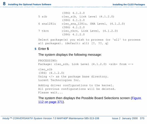
Intuity™ CONVERSANT® System Version 7.0 MAP/40P Maintenance 585-313-108 Issue 2 January 2000 370
8 Installing the Optional Feature Software
Installing the CLEO Packages
(386) 4.1.2.05 sib cleo_sib, Link Level (4.1.2.0)
(386) 4.1.2.06 sna128lu cleo_sna_128lu, SNA Level, (4.1.2.0)
(386) 4.1.2.07 tkrn cleo_tkrn, Link Level, (4.1.2.0)
(386) 4.1.2.0
Select package(s) you wish to process (or ‘all’ to process all packages). (default: all) [?, ??, q]
5 Enter 5
The system displays the following message:
PROCESSING:Package: cleo_sib, Link Level (4.1.2.0) <sib> from <->
cleo_sib(386) (4.1.2.0)Using </> as the package base directory.Lucent Technologies Inc.
Adding driver configurations to the kernel.All previous configurations will be deleted.Please wait...
The system then displays the Possible Board Selections screen (Figure 112 on page 371).

Intuity™ CONVERSANT® System Version 7.0 MAP/40P Maintenance 585-313-108 Issue 2 January 2000 371
8 Installing the Optional Feature Software
Installing the CLEO Packages
Figure 112. Possible Board Selections Screen
6 Enter 1
The system displays the following message:
You have selected Cleo FIFO SIB.Is this correct (y/n)?
7 Enter y
The system then displays the IRQ Selections screen (Figure 113 on page 372).
Cleo ADD Board Options--------------------------Possible Board Selections
1. Cleo FIFO SIB2. Cleo Microchannel FIFO SIB3. Cleo PC 201 Modem Board4. Cleo PC SIB5. Cleo Microchannel SIB6. ICOT SIB7. ICOT Microchannel SIB
Please enter selection or q to quit:

Intuity™ CONVERSANT® System Version 7.0 MAP/40P Maintenance 585-313-108 Issue 2 January 2000 372
8 Installing the Optional Feature Software
Installing the CLEO Packages
Figure 113. IRQ Selections Screen
8 Enter the appropriate IRQ as determined by the hardware resource allocator.
The system displays the following message:
Validating you selection...Please waitYou have selected X. Is this correct (y/n)?
9 Enter y
The system then displays the I/O Address Selections screen (Figure 114 on page 373).
Cleo ADD Board Options--------------------------
IRQ Selections
5910111213
Please enter selection or q to quit:

Intuity™ CONVERSANT® System Version 7.0 MAP/40P Maintenance 585-313-108 Issue 2 January 2000 373
8 Installing the Optional Feature Software
Installing the CLEO Packages
Figure 114. I/O Address Selections Screen
10 Enter the appropriate I/O address as determined by the hardware resource allocator.
The system displays the following message:
You have selected X. Is this correct (y/n)?
11 Enter y
The system displays the Board Configuration screen (Figure 115 on page 374).
Cleo ADD Board Options--------------------------I/O Address Selections
0x2500x2600x2B00x2E00x3800x3A00x3E0
Please enter selection, <CR> for default of 0x380 or q to quit:

Intuity™ CONVERSANT® System Version 7.0 MAP/40P Maintenance 585-313-108 Issue 2 January 2000 374
8 Installing the Optional Feature Software
Installing the CLEO Packages
Figure 115. Board Configuration Screen
12 Enter y
The system displays the following message:
Board configuration successfully added.Do you wish to add another board?
13 Enter n
Cleo ADD Board Options--------------------------
Configuration for board 1 is:
Board Description = Cleo FIFO SIBIRQ = XI/O Address = X - X
This board has 1 physical port(s).When configuring the Link Service record(s) of the Cleo SNA Server use the following mapping:
Boards Physical Port # Link Service Port #---------------------- -------------------
1 1
Is this configuration acceptable:

Intuity™ CONVERSANT® System Version 7.0 MAP/40P Maintenance 585-313-108 Issue 2 January 2000 375
8 Installing the Optional Feature Software
Installing the CLEO Packages
The system then displays the following message and the system prompt:
Installation of the cleo_sib, Link Level (4.1.2.0) (sib) was successful.
Installing the cleo_sna_1281u Package
To install the cleo_sna_1281u package, do the following:
1 Make sure you have loaded at least one of the following packages:
~ cleo_tkrn
~ cleo_sib
2 Insert the cartridge tape labeled “CLEO 4.1.2.0 1 of 1” into the cartridge tape drive.
3 Enter pkgadd -d ctape1
The system displays the following message:
Insert a cartridge into Tape Drive 1.Type [go] when ready,
or [q] to quit: (default: go)
4 Press ENTER.
The system displays the following message:
Installation in progress. Do not remove the cartridge.

Intuity™ CONVERSANT® System Version 7.0 MAP/40P Maintenance 585-313-108 Issue 2 January 2000 376
8 Installing the Optional Feature Software
Installing the CLEO Packages
The following packages are available:
1 cleo3270 cleo_3270, Feature Level 1 (4.1.2.0)(386) 4.1.2.0
2 cleoHTE cleo_hte, Feature Level 2 (4.1.2.0)(386) 4.1.2.0
3 mgmt cleo_mgmt, Feature Level 1 (4.1.2.0)(386) 4.1.2.0
4 netman cleo_netman, Feature Level 1 (4.1.2.0)(386) 4.1.2.0
5 sib cleo_sib, Link Level (4.1.2.0)(386) 4.1.2.0
6 sna128lu cleo_sna_128lu, SNA Level, (4.1.2.0)(386) 4.1.2.0
7 tkrn cleo_tkrn, Link Level, (4.1.2.0)(386) 4.1.2.0
Select package(s) you wish to process (or ‘all’ to process all packages). (default: all) [?, ??, q]
5 Enter 6
The system displays the following message:
PROCESSING:Package: cleo_sna_1281u, SNA Level (4.1.2.0) <sna1281u> from <->
cleo_sna_1281u(386) (4.1.2.0)

Intuity™ CONVERSANT® System Version 7.0 MAP/40P Maintenance 585-313-108 Issue 2 January 2000 377
8 Installing the Optional Feature Software
Installing the CLEO Packages
Using </> as the package base directory.Lucent Technologies Inc.
Adding driver configurations to the kernel.All previous configurations will be deleted.Please wait...
Enabling Link Level Drivers
cleo_sna1281u, Link Level (4.1.2.0) installation has detected the following SDLC Frame Size.
265 (256 + 9) bytes
Do you want to change the SDLC Frame Size? (y/n)
6 Enter n
The system displays the following message:
You can use the "cleohw.cfg" utility should you need to change the SDLC Frame Size after the installation.
Enter <CR> to continue.
7 Press ENTER.
The system displays the following message:
A kernel link is required to activate the cleo_sna_1281u, SNA Level (4.1.2.0) installation. In most cases the kernel must be relinked now. However, if the cleo_slim package is to be installed before using the Cleo product the kernel link can

Intuity™ CONVERSANT® System Version 7.0 MAP/40P Maintenance 585-313-108 Issue 2 January 2000 378
8 Installing the Optional Feature Software
Installing the CLEO Packages
be postponed. cleo_slim will relink the kernel automatically when installed.
Do you want to link the kernel now?
8 Enter y
The system displays the following message:
The Unix kernel will be rebuilt now.This will take some time. Please wait
The system then displays the following message and the system prompt:
Installation of the cleo_sna_1281u, SNA Level (4.1.2.0) (sna1281u) was successful.
Installing the cleo_3270 Package
To install the cleo_3270 package, do the following:
1 Make sure you have loaded at least one of the following packages:
~ cleo_tkrn and or cleo_sib
~ cleo_sna_1281u
2 Insert the cartridge tape labeled “CLEO 4.1.2.0 1 of 1” into the cartridge tape drive.

Intuity™ CONVERSANT® System Version 7.0 MAP/40P Maintenance 585-313-108 Issue 2 January 2000 379
8 Installing the Optional Feature Software
Installing the CLEO Packages
3 Enter pkgadd -d ctape1
The system displays the following message:
Insert a cartridge into Tape Drive 1.Type [go] when ready,
or [q] to quit: (default: go)
4 Press ENTER.
The system displays the following message:
Installation in progress. Do not remove the cartridge.
The following packages are available:
1 cleo3270 cleo_3270, Feature Level 1 (4.1.2.0)(386) 4.1.2.0
2 cleoHTE cleo_hte, Feature Level 2 (4.1.2.0)(386) 4.1.2.0
3 mgmt cleo_mgmt, Feature Level 1 (4.1.2.0)(386) 4.1.2.0
4 netman cleo_netman, Feature Level 1 (4.1.2.0)(386) 4.1.2.0
5 sib cleo_sib, Link Level (4.1.2.0)(386) 4.1.2.0
6 sna128lu cleo_sna_128lu, SNA Level, (4.1.2.0)(386) 4.1.2.0
7 tkrn cleo_tkrn, Link Level, (4.1.2.0)(386) 4.1.2.0

Intuity™ CONVERSANT® System Version 7.0 MAP/40P Maintenance 585-313-108 Issue 2 January 2000 380
8 Installing the Optional Feature Software
Installing the CLEO Packages
Select package(s) you wish to process (or ‘all’ to process all packages). (default: all) [?,??, q]
5 Enter 1
The system displays the following message:
PROCESSING:Package: cleo_3270, Feature Level 1 (4.1.2.0) <cleo3270> from <->
cleo_3270(386) (4.1.2.0)Using </> as the package base directory.Lucent Technologies Inc.
The system displays several status messages and then the following message:
Installing cleo_3270, Feature Level 1 (4.1.2.0) (cleo3270).Please wait.
The system then displays the following message and the system prompt:
Installation of the cleo_3270, Feature Level 1 (4.1.2.0) (cleo3270) was successful.

Intuity™ CONVERSANT® System Version 7.0 MAP/40P Maintenance 585-313-108 Issue 2 January 2000 381
8 Installing the Optional Feature Software
Installing the CLEO Packages
Installing the cleo_mgmt Package
To install the cleo_mgmt package, do the following:
1 Make sure you have loaded at least one of the following packages:
~ cleo_tkrn and or cleo_sib
~ cleo_sna_1281u
~ cleo_3270
2 Insert the cartridge tape labeled “CLEO 4.1.2.0 1 of 1” into the cartridge tape drive.
3 Enter pkgadd -d ctape1
The system displays the following message:
Insert a cartridge into Tape Drive 1.Type [go] when ready,
or [q] to quit: (default: go)
4 Press ENTER.
The system displays the following message:
Installation in progress. Do not remove the cartridge.
The following packages are available:
1 cleo3270 cleo_3270, Feature Level 1 (4.1.2.0)(386) 4.1.2.0

Intuity™ CONVERSANT® System Version 7.0 MAP/40P Maintenance 585-313-108 Issue 2 January 2000 382
8 Installing the Optional Feature Software
Installing the CLEO Packages
2 cleoHTE cleo_hte, Feature Level 2 (4.1.2.0)(386) 4.1.2.0
3 mgmt cleo_mgmt, Feature Level 1 (4.1.2.0)(386) 4.1.2.0
4 netman cleo_netman, Feature Level 1 (4.1.2.0)(386) 4.1.2.0
5 sib cleo_sib, Link Level (4.1.2.0)(386) 4.1.2.0
6 sna128lu cleo_sna_128lu, SNA Level, (4.1.2.0)(386) 4.1.2.0
7 tkrn cleo_tkrn, Link Level, (4.1.2.0)(386) 4.1.2.0
Select package(s) you wish to process (or ‘all’ to process all packages). (default: all) [?,??, q]
5 Enter 3
The system displays the following message:
PROCESSING:Package: cleo_mgmt, Feature Level 1 (4.1.2.0) <mgmt> from <->
cleo_mgmt(386) (4.1.2.0)Using </> as the package base directory.Lucent Technologies Inc.
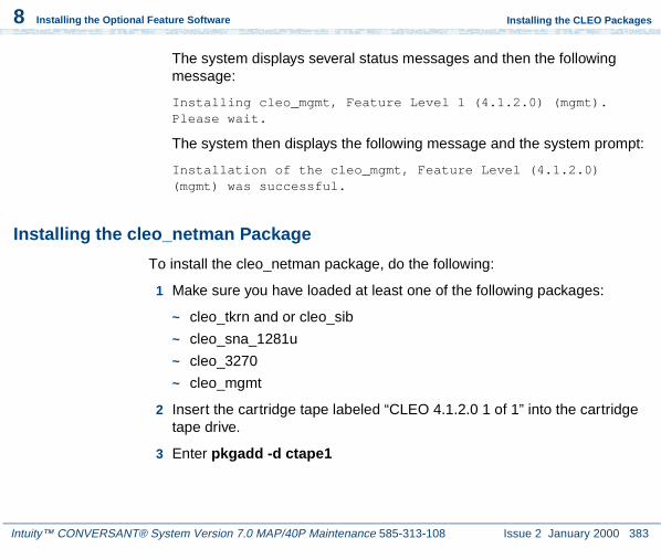
Intuity™ CONVERSANT® System Version 7.0 MAP/40P Maintenance 585-313-108 Issue 2 January 2000 383
8 Installing the Optional Feature Software
Installing the CLEO Packages
The system displays several status messages and then the following message:
Installing cleo_mgmt, Feature Level 1 (4.1.2.0) (mgmt).Please wait.
The system then displays the following message and the system prompt:
Installation of the cleo_mgmt, Feature Level (4.1.2.0) (mgmt) was successful.
Installing the cleo_netman Package
To install the cleo_netman package, do the following:
1 Make sure you have loaded at least one of the following packages:
~ cleo_tkrn and or cleo_sib
~ cleo_sna_1281u
~ cleo_3270
~ cleo_mgmt
2 Insert the cartridge tape labeled “CLEO 4.1.2.0 1 of 1” into the cartridge tape drive.
3 Enter pkgadd -d ctape1

Intuity™ CONVERSANT® System Version 7.0 MAP/40P Maintenance 585-313-108 Issue 2 January 2000 384
8 Installing the Optional Feature Software
Installing the CLEO Packages
The system displays the following message:
Insert a cartridge into Tape Drive 1.Type [go] when ready,
or [q] to quit: (default: go)
4 Press ENTER.
The system displays the following message:
Installation in progress. Do not remove the cartridge.
The following packages are available:
1 cleo3270 cleo_3270, Feature Level 1 (4.1.2.0)(386) 4.1.2.0
2 cleoHTE leo_hte, Feature Level 2 (4.1.2.0)(386) 4.1.2.0
3 mgmt cleo_mgmt, Feature Level 1 (4.1.2.0)(386) 4.1.2.0
4 netman cleo_netman, Feature Level 1 (4.1.2.0)(386) 4.1.2.0
5 sib cleo_sib, Link Level (4.1.2.0)(386) 4.1.2.0
6 sna128lu cleo_sna_128lu, SNA Level, (4.1.2.0)(386) 4.1.2.0
7 tkrn cleo_tkrn, Link Level, (4.1.2.0)(386) 4.1.2.0
Select package(s) you wish to process (or ‘all’ to process all packages). (default: all) [?,??, q]
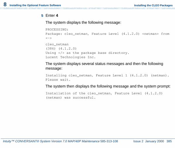
Intuity™ CONVERSANT® System Version 7.0 MAP/40P Maintenance 585-313-108 Issue 2 January 2000 385
8 Installing the Optional Feature Software
Installing the CLEO Packages
5 Enter 4
The system displays the following message:
PROCESSING:Package: cleo_netman, Feature Level (4.1.2.0) <netman> from <->
cleo_netman(386) (4.1.2.0)Using </> as the package base directory.Lucent Technologies Inc.
The system displays several status messages and then the following message:
Installing cleo_netman, Feature Level 1 (4.1.2.0) (netman).Please wait.
The system then displays the following message and the system prompt:
Installation of the cleo_netman, Feature Level (4.1.2.0) (netman) was successful.

Intuity™ CONVERSANT® System Version 7.0 MAP/40P Maintenance 585-313-108 Issue 2 January 2000 386
8 Installing the Optional Feature Software
Installing the CLEO Packages
Installing the cleo_HTE Package
To install the cleo_HTE package, do the following:
1 Make sure you have loaded at least one of the following packages:
~ cleo_tkrn and or cleo_sib
~ cleo_sna_1281u
~ cleo_3270
~ cleo_mgmt
~ cleo_netman
2 Insert the cartridge tape labeled “CLEO 4.1.2.0 1 of 1” into the cartridge tape drive.
3 Enter pkgadd -d ctape1
The system displays the following message:
Insert a cartridge into Tape Drive 1.Type [go] when ready,
or [q] to quit: (default: go)
4 Press ENTER.
The system displays the following message:
Installation in progress. Do not remove the cartridge.

Intuity™ CONVERSANT® System Version 7.0 MAP/40P Maintenance 585-313-108 Issue 2 January 2000 387
8 Installing the Optional Feature Software
Installing the CLEO Packages
The following packages are available:
1 cleo3270 cleo_3270, Feature Level 1 (4.1.2.0)(386) 4.1.2.0
2 cleoHTE cleo_hte, Feature Level 2 (4.1.2.0)(386) 4.1.2.0
3 mgmt cleo_mgmt, Feature Level 1 (4.1.2.0)(386) 4.1.2.0
4 netman cleo_netman, Feature Level 1 (4.1.2.0)(386) 4.1.2.0
5 sib cleo_sib, Link Level (4.1.2.0)(386) 4.1.2.0
6 sna128lu cleo_sna_128lu, SNA Level, (4.1.2.0)(386) 4.1.2.0
7 tkrn cleo_tkrn, Link Level, (4.1.2.0)(386) 4.1.2.0
Select package(s) you wish to process (or ‘all’ to process all packages). (default: all) [?,??, q]
5 Enter 2
The system displays the following message:
PROCESSING:Package: cleo_HTE, Feature Level (4.1.2.0) <cleoHTE> from <->
cleo_HTE(386) (4.1.2.0)

Intuity™ CONVERSANT® System Version 7.0 MAP/40P Maintenance 585-313-108 Issue 2 January 2000 388
8 Installing the Optional Feature Software
Installing the CLEO Packages
Using </> as the package base directory.Lucent Technologies Inc.
The system then displays the following message and the system prompt:
Installation of the cleo_HTE, Feature Level (4.1.2.0) (cleoHTE) was successful.
Completing the Installation
When all of the chosen packages have been installed the system displays the following message:
1 Remove the cartridge tape from the cartridge tape drive.
2 Reboot the system. See “Reboot the System,” in “Common System Procedures,” in the Intuity CONVERSANT System Reference, 585-313-205.
Note: If you should want to change IRQ, I/O Address, RAM Address, and/or SDLC frame size after installing the CLEO software, see cleohw.cfg in the procedure titled “Changing Hardware Configuration using cleohw.cfg” in Chapter 3, “Software installation,” of the CLEO Administration Guide.
You have completed the installation of the CLEO packages. To finish the installation of the host software, go to Installing the Host Packages on page 389.

Intuity™ CONVERSANT® System Version 7.0 MAP/40P Maintenance 585-313-108 Issue 2 January 2000 389
8 Installing the Optional Feature Software
Installing the Host Packages
Installing the Host Packages
When installing the Intuity CONVERSANT Host software, the order in which you install the packages is very important.
Note: The Intuity CONVERSANT VIS V7.0 set must be installed before any of the Host packages. If the appropriate hardware (FIFO/SIB and/or Token Ring) is not installed at this time, you may get an error message when you stop and start the voice system:
Make sure you perform the procedures to install the Host software in the following order:
1 Installing the Synchronous Host Interface Package on page 389
2 Installing the 3270 Enhanced File Transfer Package on page 391
3 Installing the NetView Alarm Interface Package on page 393
Installing the Synchronous Host Interface Package
Use the following procedure to install this optional feature package:
1 If you are not already logged in as root, do so now.
2 Stop the voice system. See “Administer the Voice System,” in “Common System Procedures,” in the Intuity CONVERSANT System Reference, 585-313-205, for the procedure.

Intuity™ CONVERSANT® System Version 7.0 MAP/40P Maintenance 585-313-108 Issue 2 January 2000 390
8 Installing the Optional Feature Software
Installing the Host Packages
3 Insert the diskette labeled “Synchronous Host Interface Package 1 of 1” into the diskette drive.
4 Enter pkgadd -d diskette1
The system displays the following message:
Insert diskette into Floppy Drive 1.Type [go] when ready,
or [q] to quit: (default: go)
5 Press ENTER.
The system displays the following message:
Installation in progress -- do not remove the diskette.
The following packages are available: 1. synchost INTUITY Synchronous Host Interface
Package (i486)
Select package(s) you wish to process (or ‘all’ to process all packages). (default: all) [?,??,q]:
6 Press ENTER.
The system displays the following message:
PROCESSING:Set: INTUITY Synchronous Host Interface Package (synchost) from <diskette1>

Intuity™ CONVERSANT® System Version 7.0 MAP/40P Maintenance 585-313-108 Issue 2 January 2000 391
8 Installing the Optional Feature Software
Installing the Host Packages
INTUITY Synchronous Host Interface Package(i486)Using </> as the package base directory.Lucent Technologies Inc.
The system displays several status messages and then the following message:
Installation of Synchronous Host Interface Package (synchost) was successful.
Insert diskette into Floppy Drive 1.Type [go] when ready,
or [q] to quit: (default: go)
7 Enter q
8 Make sure that the light on the floppy disk drive is off and remove the diskette.
Installing the 3270 Enhanced File Transfer Package
To install the 3270 Enhanced File Transfer package, do the following:
1 If you are not already logged in as root, do so now.
2 Enter pkgadd -d diskette1

Intuity™ CONVERSANT® System Version 7.0 MAP/40P Maintenance 585-313-108 Issue 2 January 2000 392
8 Installing the Optional Feature Software
Installing the Host Packages
The system displays the following message:
Insert diskette into Floppy Drive 1.Type [go] when ready,
or [q] to quit: (default: go)
3 Insert the diskette labeled “3270 Enhanced File Transfer 1 of 1” into the diskette drive.
4 Press ENTER.
The system displays the following message:
Installation in progress -- do not remove the diskette.
The following packages are available: 1. fts INTUITY 3270 Enhanced File Transfer
Package (i486)
Select package(s) you wish to process (or ‘all’ to process all packages). (default: all) [?,??,q]:
5 Press ENTER.
The system displays the following message:
PROCESSING:Set: INTUITY 3270 Enhanced File Transfer Package (fts) from <diskette1>
INTUITY 3270 Enhanced File Transfer Package(i486)

Intuity™ CONVERSANT® System Version 7.0 MAP/40P Maintenance 585-313-108 Issue 2 January 2000 393
8 Installing the Optional Feature Software
Installing the Host Packages
Using </> as the package base directory.Lucent Technologies Inc.
The system displays several status messages and then the following message:
Installation of INTUITY 3270 Enhanced File Transfer Package (fts) was successful.
Insert diskette into Floppy Drive 1.Type [go] when ready,
or [q] to quit: (default: go)
6 Enter q
7 Remove the diskette labeled “3270 Enhanced File Transfer 1 of 1” from the diskette drive.
Installing the NetView Alarm Interface Package
To install the NewView Alarm Interface package, do the following:
1 If you are not already logged in as root, do so now.
2 Enter pkgadd -d diskette1
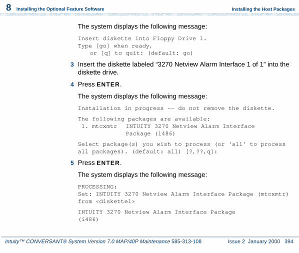
Intuity™ CONVERSANT® System Version 7.0 MAP/40P Maintenance 585-313-108 Issue 2 January 2000 394
8 Installing the Optional Feature Software
Installing the Host Packages
The system displays the following message:
Insert diskette into Floppy Drive 1.Type [go] when ready,
or [q] to quit: (default: go)
3 Insert the diskette labeled “3270 Netview Alarm Interface 1 of 1” into the diskette drive.
4 Press ENTER.
The system displays the following message:
Installation in progress -- do not remove the diskette.
The following packages are available: 1. mtcxmtr INTUITY 3270 Netview Alarm Interface
Package (i486)
Select package(s) you wish to process (or ‘all’ to process all packages). (default: all) [?,??,q]:
5 Press ENTER.
The system displays the following message:
PROCESSING:Set: INTUITY 3270 Netview Alarm Interface Package (mtcxmtr) from <diskette1>
INTUITY 3270 Netview Alarm Interface Package(i486)
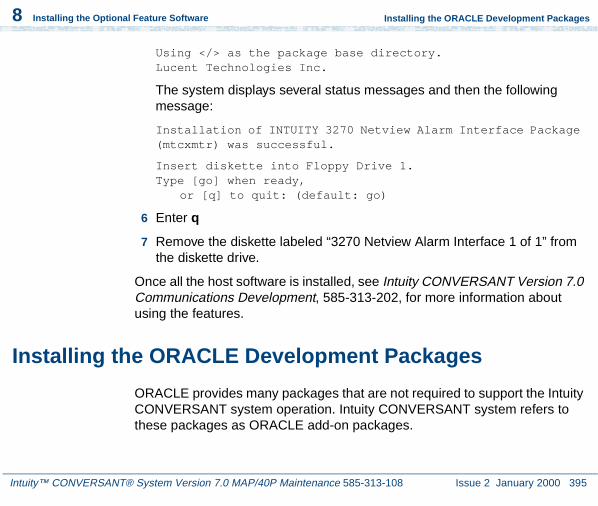
Intuity™ CONVERSANT® System Version 7.0 MAP/40P Maintenance 585-313-108 Issue 2 January 2000 395
8 Installing the Optional Feature Software
Installing the ORACLE Development Packages
Using </> as the package base directory.Lucent Technologies Inc.
The system displays several status messages and then the following message:
Installation of INTUITY 3270 Netview Alarm Interface Package (mtcxmtr) was successful.
Insert diskette into Floppy Drive 1.Type [go] when ready,
or [q] to quit: (default: go)
6 Enter q
7 Remove the diskette labeled “3270 Netview Alarm Interface 1 of 1” from the diskette drive.
Once all the host software is installed, see Intuity CONVERSANT Version 7.0 Communications Development, 585-313-202, for more information about using the features.
Installing the ORACLE Development Packages
ORACLE provides many packages that are not required to support the Intuity CONVERSANT system operation. Intuity CONVERSANT system refers to these packages as ORACLE add-on packages.

Intuity™ CONVERSANT® System Version 7.0 MAP/40P Maintenance 585-313-108 Issue 2 January 2000 396
8 Installing the Optional Feature Software
Installing the ORACLE Development Packages
This section describes the installation procedures for each add-on package. For detailed installation and removal information, see the ORACLE7 for Intel UNIX SVR4 (iABI) Installation & Configuration Guide.
Package List
The ORACLE development packages are included on the following 3 tapes:
• ORACLE 7 Pro*C Package
• ORACLE 7 Developer Toolkit – which contains ORACLE FORMS 4.5.7.12 and ORACLE Reports 2.5.5.4.0
! CAUTION:The ORACLE Developer Toolkit cartridge tape contains more ORACLE products than those listed. However, Intuity CONVERSANT system customers must NOT install products that are not listed. Some of the products are already included in the various Intuity CONVERSANT system packages, while other products are not authorized to be used by the Intuity CONVERSANT system customers. A violation of the recommendation may result into the corruption of the Intuity CONVERSANT system software configuration and may be illegal usage of the ORACLE software.
• ORACLE 7 Patch 19
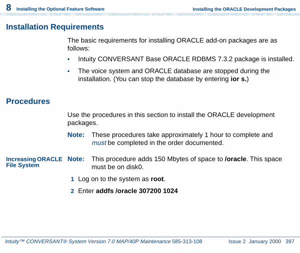
Intuity™ CONVERSANT® System Version 7.0 MAP/40P Maintenance 585-313-108 Issue 2 January 2000 397
8 Installing the Optional Feature Software
Installing the ORACLE Development Packages
Installation Requirements
The basic requirements for installing ORACLE add-on packages are as follows:
• Intuity CONVERSANT Base ORACLE RDBMS 7.3.2 package is installed.
• The voice system and ORACLE database are stopped during the installation. (You can stop the database by entering ior s.)
Procedures
Use the procedures in this section to install the ORACLE development packages.
Note: These procedures take approximately 1 hour to complete and must be completed in the order documented.
Increasing ORACLE File System
Note: This procedure adds 150 Mbytes of space to /oracle. This space must be on disk0.
1 Log on to the system as root.
2 Enter addfs /oracle 307200 1024
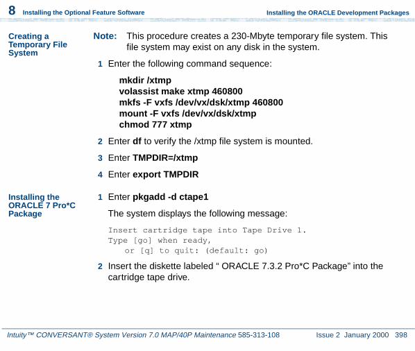
Intuity™ CONVERSANT® System Version 7.0 MAP/40P Maintenance 585-313-108 Issue 2 January 2000 398
8 Installing the Optional Feature Software
Installing the ORACLE Development Packages
Creating a Temporary File System
Note: This procedure creates a 230-Mbyte temporary file system. This file system may exist on any disk in the system.
1 Enter the following command sequence:
mkdir /xtmpvolassist make xtmp 460800mkfs -F vxfs /dev/vx/dsk/xtmp 460800mount -F vxfs /dev/vx/dsk/xtmpchmod 777 xtmp
2 Enter df to verify the /xtmp file system is mounted.
3 Enter TMPDIR=/xtmp
4 Enter export TMPDIR
Installing the ORACLE 7 Pro*C Package
1 Enter pkgadd -d ctape1
The system displays the following message:
Insert cartridge tape into Tape Drive 1.Type [go] when ready,
or [q] to quit: (default: go)
2 Insert the diskette labeled “ ORACLE 7.3.2 Pro*C Package” into the cartridge tape drive.

Intuity™ CONVERSANT® System Version 7.0 MAP/40P Maintenance 585-313-108 Issue 2 January 2000 399
8 Installing the Optional Feature Software
Installing the ORACLE Development Packages
3 Press ENTER.
The system displays the following message:
Installation in progress -- do not remove the cartridge.
The following packages are available: 1. proc INTUITY ORACLE 7 Pro*C Package
(i486) i.3.1
Select package(s) you wish to process (or ‘all’ to process all packages). (default: all) [?,??,q]:
4 Press ENTER.
The system displays the following message:
PROCESSING:Set: INTUITY ORACLE 7 Pro*C Package (proc) from <ctape1>
INTUITY ORACLE 7 Pro*C Package(i486)Using </> as the package base directory.Lucent Technologies Inc.
The system displays several status messages and then the following message:
Installation of INTUITY ORACLE 7 Pro*C Package(proc) was successful.

Intuity™ CONVERSANT® System Version 7.0 MAP/40P Maintenance 585-313-108 Issue 2 January 2000 400
8 Installing the Optional Feature Software
Installing the ORACLE Development Packages
Insert cartridge tape into Tape Drive 1.Type [go] when ready,
or [q] to quit: (default: go)
5 Enter q
6 Make sure that the light on the cartridge tape drive is off and remove the tape.
Installing the ORACLE Developer 2000 Toolkit
Note: To select a response other than the screen default, use the TAB key to highlight the selection, and then press ENTER.
1 Insert the tape labeled “ ORACLE 7.3.2 Developer 2000 Toolkit” into the cartridge tape drive.
2 Enter the following command sequence:
mkdir /xtmp/d2k132chmod 777 /xtmp/d2k132su - oraclecd /xtmp/d2k132cpio -icvdB < /dev/rmt/ctape1cd /oracle/orainst./orainst
The system displays the following message:
Select the Installer Activity

Intuity™ CONVERSANT® System Version 7.0 MAP/40P Maintenance 585-313-108 Issue 2 January 2000 401
8 Installing the Optional Feature Software
Installing the ORACLE Development Packages
3 Select Install/Upgrade/Patch Software Only.
The system displays the following message:
Select the Installer option
4 Select New Product.
The system displays the following message:
Enter mount point for your software installation.
5 Enter /oracle
The system displays the following message:
Complete $ORACLE_HOME location:
/oracle/app/oracle/product
6 Enter 7.3.2
7 Press ENTER at the confirmation message.
The system displays the following message:
Do you want to create DB objects also?
8 Select No.
The system displays the Logging and Status screen:
9 Press ENTER.
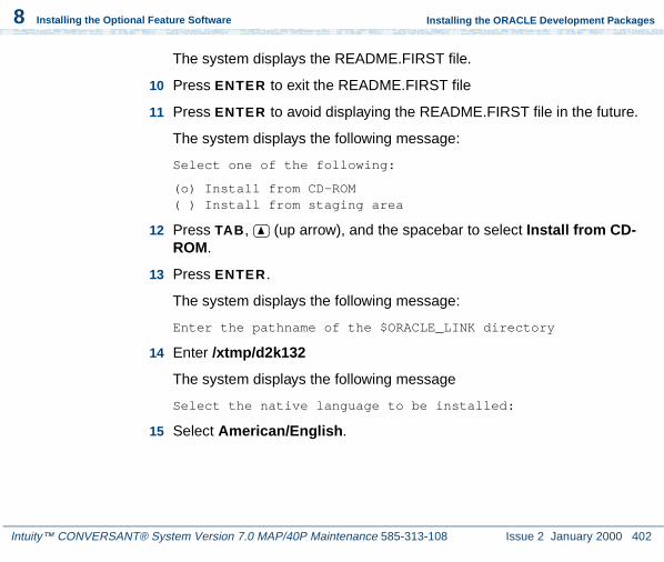
Intuity™ CONVERSANT® System Version 7.0 MAP/40P Maintenance 585-313-108 Issue 2 January 2000 402
8 Installing the Optional Feature Software
Installing the ORACLE Development Packages
The system displays the README.FIRST file.
10 Press ENTER to exit the README.FIRST file
11 Press ENTER to avoid displaying the README.FIRST file in the future.
The system displays the following message:
Select one of the following:
(o) Install from CD-ROM( ) Install from staging area
12 Press TAB, (up arrow), and the spacebar to select Install from CD-ROM.
13 Press ENTER.
The system displays the following message:
Enter the pathname of the $ORACLE_LINK directory
14 Enter /xtmp/d2k132
The system displays the following message
Select the native language to be installed:
15 Select American/English.

Intuity™ CONVERSANT® System Version 7.0 MAP/40P Maintenance 585-313-108 Issue 2 January 2000 403
8 Installing the Optional Feature Software
Installing the ORACLE Development Packages
The system displays the following message
The /oracle/app/oracle/product/7.3.2/orainst/root.sh file already exists. Select one of the following actions:
( ) Append root-related actions to this file(o) Create new root.sh file
16 Press TAB, (up arrow), and the spacebar to select Append root-related actions to this file.
17 Press ENTER.
The system displays the following message
Post-installation steps that need to be run by root will be written to /oracle/app/oracle/product/7.3.2/orainst/root.sh
18 Press ENTER.
The system displays the following message
Install online help for:
( ) All Products Being Installed(o) Products of Your Choice( ) No Products
19 Press TAB, (up arrow), and the spacebar to select All Products Being Installed.

Intuity™ CONVERSANT® System Version 7.0 MAP/40P Maintenance 585-313-108 Issue 2 January 2000 404
8 Installing the Optional Feature Software
Installing the ORACLE Development Packages
20 Press ENTER.
The system displays the following message:
Do you want to install UNIX-specific documentation?
21 Select Yes.
The system displays the following message:
Install product documentation from the product documentation CD-ROM for:
(o) All Product Being Installed( ) Products of Your Choice( ) No Products
22 Select All Products Being Installed.
The system displays the following message:
Enter the pathname for your $ORACLE_DOC directory
/oracle/app/oracle/doc
23 Press ENTER to select the default pathname.
The system displays the Software Assist Manager screen.
24 Use (down arrow) and space bar to highlight the following products:
~ ORACLE FORMS 4.5.7.12
~ ORACLE Reports 2.5.5.4.0

Intuity™ CONVERSANT® System Version 7.0 MAP/40P Maintenance 585-313-108 Issue 2 January 2000 405
8 Installing the Optional Feature Software
Installing the ORACLE Development Packages
25 Press TAB to select Install, and then press ENTER.
The system displays the following message:
Would you like to install the PL/SQL Procedure Builder demos?(Note: this will take up 5120 bytes of disk space).
26 Select Yes.
The system displays the following message:
Please enter the directory where the X-Windows libraries (libxt.a, libX11.a) may be found:
27 Enter /usr/X/lib
The system displays the following message:
Please enter the directory where the MOTIF library (libXm.a) is located:
28 Enter /usr/X/lib
The system displays the following message:
Would you like to install the ORACLE Graphics 2.5 demos?(Note: this will take up 4405248 bytes of disk space).
29 Select No.

Intuity™ CONVERSANT® System Version 7.0 MAP/40P Maintenance 585-313-108 Issue 2 January 2000 406
8 Installing the Optional Feature Software
Installing the ORACLE Development Packages
The system displays the following message:
Select one or more user interfaces for Oracle Forms...
(x) Character Mode Interface( ) Motif Bitmapped Interface
30 Select Character Mode Interface.
The system displays the following message:
Would you like to install the ORACLE Forms demos?(Note: this will take up 7963648 bytes of disk space).
31 Select Yes.
The system displays the following message:
Select one or more user interfaces for Oracle Reports 2.5...
(x) Character Mode Interface( ) Motif Bitmapped Interface
32 Select Character Mode Interface.
The system displays the following message:
Would you like to install the ORACLE Reports 2.5 demos?(Note: this will take up 27224064 bytes of disk space).
33 Select Yes.

Intuity™ CONVERSANT® System Version 7.0 MAP/40P Maintenance 585-313-108 Issue 2 January 2000 407
8 Installing the Optional Feature Software
Post Installation Setup
After approximately 30 minutes, the system displays a confirmation message.
34 Select OK.
35 Type x at the Software Asset Manager screen.
36 Press y at the confirmation message.
Post Installation Setup
1 At the UNIX system prompt, enter su - root
2 Enter the root password.
3 Enter cd /oracle/app/oracle/product/7.3.2/orainst
4 Enter ./root.sh
The system displays the following message:
The following environment variables are set as
ORACLE_OWNER= oracleORACLE_HOME= oracleORACLE_SID= A
Are these settings correct (Y/N)? [Y}
5 Press ENTER.

Intuity™ CONVERSANT® System Version 7.0 MAP/40P Maintenance 585-313-108 Issue 2 January 2000 408
8 Installing the Optional Feature Software
Post Installation Setup
The system displays the following message:
Enter the full pathname of the local bin directory [/usr/bin]:
6 Press ENTER.
7 The procedure is complete when the UNIX system prompt is returned.
Installing the ORACLE 7 Patch 19
1 Log on to the system as root.
2 Insert the tape labeled “ ORACLE 7.3.2 Patch 19” into the cartridge tape drive.
3 Enter the following command sequence:
cd /xtmprm -rf d2k132cpio -icvdB < /dev/rmt/ctape1chmod 444 *su - oraclemkdir /oracle/app/oracle/product/7.3.2/D2K132_19cd /oracle/app/oracle/product/7.3.2/D2K132_19
The system places you in the directory that you created. The files will be installed to this directory from /xtmp.
4 Enter the following command sequence:
tar -xvf /xtmp/tar.patch19
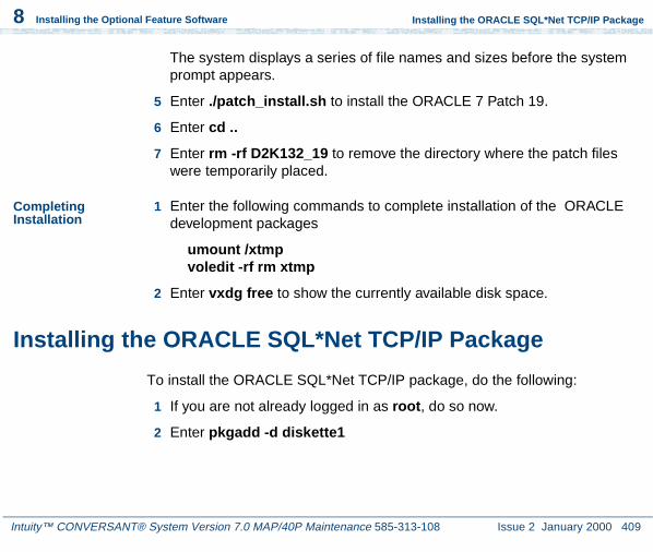
Intuity™ CONVERSANT® System Version 7.0 MAP/40P Maintenance 585-313-108 Issue 2 January 2000 409
8 Installing the Optional Feature Software
Installing the ORACLE SQL*Net TCP/IP Package
The system displays a series of file names and sizes before the system prompt appears.
5 Enter ./patch_install.sh to install the ORACLE 7 Patch 19.
6 Enter cd ..
7 Enter rm -rf D2K132_19 to remove the directory where the patch files were temporarily placed.
Completing Installation
1 Enter the following commands to complete installation of the ORACLE development packages
umount /xtmpvoledit -rf rm xtmp
2 Enter vxdg free to show the currently available disk space.
Installing the ORACLE SQL*Net TCP/IP Package
To install the ORACLE SQL*Net TCP/IP package, do the following:
1 If you are not already logged in as root, do so now.
2 Enter pkgadd -d diskette1

Intuity™ CONVERSANT® System Version 7.0 MAP/40P Maintenance 585-313-108 Issue 2 January 2000 410
8 Installing the Optional Feature Software
Installing the ORACLE SQL*Net TCP/IP Package
The system displays the following message:
Insert diskette into Floppy Drive 1.Type [go] when ready,
or [q] to quit: (default: go)
3 Insert the diskette labeled “SQL*NET TCP/IP for ORACLE 7.3.2” into the diskette drive.
4 Press ENTER.
The system displays the following message:
Installation in progress -- do not remove the diskette.
The following packages are available: 1. ora7sql INTUITY SQL*NET TCP/IP for ORACLE
7.3.2 (i486)
Select package(s) you wish to process (or ‘all’ to process all packages). (default: all) [?,??,q]:
5 Press ENTER.
The system displays the following message:
PROCESSING:Set: INTUITY SQL*NET TCP/IP for ORACLE 7.3.2 (ora7sql) from <diskette1>
INTUITY SQL*NET TCP/IP for ORACLE 7.3.2(i486)
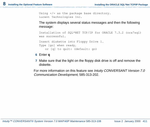
Intuity™ CONVERSANT® System Version 7.0 MAP/40P Maintenance 585-313-108 Issue 2 January 2000 411
8 Installing the Optional Feature Software
Installing the ORACLE SQL*Net TCP/IP Package
Using </> as the package base directory.Lucent Technologies Inc.
The system displays several status messages and then the following message:
Installation of SQL*NET TCP/IP for ORACLE 7.3.2 (ora7sql) was successful.
Insert diskette into Floppy Drive 1.Type [go] when ready,
or [q] to quit: (default: go)
6 Enter q
7 Make sure that the light on the floppy disk drive is off and remove the diskette.
For more information on this feature see Intuity CONVERSANT Version 7.0 Communication Development, 585-313-202.

Intuity™ CONVERSANT® System Version 7.0 MAP/40P Maintenance 585-313-108 Issue 2 January 2000 412
8 Installing the Optional Feature Software
Installing the Primary Rate Interface Packages
Installing the Primary Rate Interface Packages
Procedures to install the primary rate interface packages include:
• Installing the ISDN Primary Rate Interface Package on page 412
• Installing the Advanced Primary Rate Interface Package on page 415 (restricted availability)
Note: The ISDN primary rate interface package must be installed first.
Installing the ISDN Primary Rate Interface Package
To install the ISDN Primary Rate Interface package, do the following:
1 If you are not already logged in as root, do so now.
2 Enter pkgadd -d diskette1
The system displays the following message:
Insert diskette into Floppy Drive 1.Type [go] when ready,
or [q] to quit: (default: go)
3 Insert the diskette labeled “ISDN Primary Rate Interface Package 1 of 1” into the diskette drive.
4 Press ENTER.

Intuity™ CONVERSANT® System Version 7.0 MAP/40P Maintenance 585-313-108 Issue 2 January 2000 413
8 Installing the Optional Feature Software
Installing the Primary Rate Interface Packages
The system displays the following message:
Installation in progress -- do not remove the diskette.
The following packages are available: 1. pri INTUITY ISDN Primary Rate Interface Package (i486)
Select package(s) you wish to process (or ‘all’ to process all packages). (default: all) [?,??,q]:
5 Press ENTER.
The system displays the following message:
PROCESSING:Set: INTUITY ISDN Primary Rate Interface Package (pri) from <diskette1>
INTUITY ISDN Primary Rate Interface Package(i486)Using </> as the package base directory.Lucent Technologies Inc.
The system displays several status messages and then the following message:
WARNING: Before this package can function, the T1/E1 Driver package must be installed and then reboot the system to complete installation of the T1/E1 Driver package
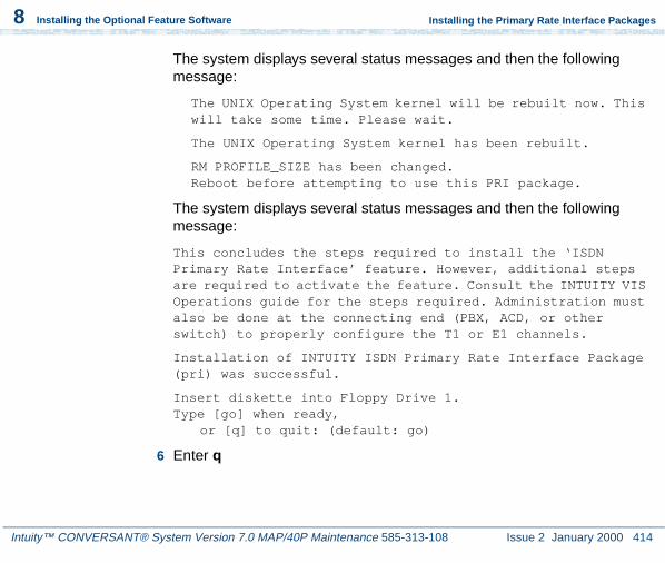
Intuity™ CONVERSANT® System Version 7.0 MAP/40P Maintenance 585-313-108 Issue 2 January 2000 414
8 Installing the Optional Feature Software
Installing the Primary Rate Interface Packages
The system displays several status messages and then the following message:
The UNIX Operating System kernel will be rebuilt now. This will take some time. Please wait.
The UNIX Operating System kernel has been rebuilt.
RM PROFILE_SIZE has been changed.Reboot before attempting to use this PRI package.
The system displays several status messages and then the following message:
This concludes the steps required to install the ‘ISDN Primary Rate Interface’ feature. However, additional steps are required to activate the feature. Consult the INTUITY VIS Operations guide for the steps required. Administration must also be done at the connecting end (PBX, ACD, or other switch) to properly configure the T1 or E1 channels.
Installation of INTUITY ISDN Primary Rate Interface Package (pri) was successful.
Insert diskette into Floppy Drive 1.Type [go] when ready,
or [q] to quit: (default: go)
6 Enter q

Intuity™ CONVERSANT® System Version 7.0 MAP/40P Maintenance 585-313-108 Issue 2 January 2000 415
8 Installing the Optional Feature Software
Installing the Primary Rate Interface Packages
7 Remove the diskette labeled “ISDN Primary Rate Interface Package 1 of 1” from the diskette drive.
8 Reboot the system. See “Reboot the System,” in “Common System Procedures,” in the Intuity CONVERSANT System Reference, 585-313-205.
For more information on this feature, see:
• Chapter 3, “Digital Telephony Interfaces,” of Intuity CONVERSANT Version 7.0 Communications Development, 585-313-202.
• Chapter 6, “Switch Interfaces,” of Intuity CONVERSANT Version 7.0 Administration, 585-313-501.
Installing the Advanced Primary Rate Interface Package
To install the Advanced Primary Rate Interface package, do the following:
1 If you are not already logged in as root, do so now.
2 Enter pkgadd -d diskette1
The system displays the following message:
Insert diskette into Floppy Drive 1.Type [go] when ready,
or [q] to quit: (default: go)

Intuity™ CONVERSANT® System Version 7.0 MAP/40P Maintenance 585-313-108 Issue 2 January 2000 416
8 Installing the Optional Feature Software
Installing the Primary Rate Interface Packages
3 Insert the diskette labeled “Advanced PRI Package 1 of 1” into the diskette drive.
4 Press ENTER.
The system displays the following message:
Installation in progress -- do not remove the diskette.
The following packages are available: 1. npri INTUITY Advanced PRI Package
(i486)
Select package(s) you wish to process (or ‘all’ to process all packages). (default: all) [?,??,q]:
5 Press ENTER.
The system displays the following message:
PROCESSING:Set: INTUITY Advanced PRI Package (npri) from <diskette1>
INTUITY Advanced PRI Package(i486)Using </> as the package base directory.Lucent Technologies Inc.

Intuity™ CONVERSANT® System Version 7.0 MAP/40P Maintenance 585-313-108 Issue 2 January 2000 417
8 Installing the Optional Feature Software
Installing the Script Builder Package
The system displays several status messages and then the following message:
This concludes the steps required to install the ‘Advanced PRI’ feature.
Installation of INTUITY Advanced PRI Package (npri) was successful.
Insert diskette into Floppy Drive 1.Type [go] when ready,
or [q] to quit: (default: go)
6 Enter q
7 Remove the diskette labeled “Advanced PRI Package 1 of 1” from the diskette drive.
Installing the Script Builder Package
To install the Script Builder package, do the following:
1 If you are not already logged in as root, do so now.
2 Enter pkgadd -d diskette1

Intuity™ CONVERSANT® System Version 7.0 MAP/40P Maintenance 585-313-108 Issue 2 January 2000 418
8 Installing the Optional Feature Software
Installing the Script Builder Package
The system displays the following message:
Insert diskette into Floppy Drive 1.Type [go] when ready,
or [q] to quit: (default: go)
3 Insert the diskette labeled “Script Builder 1 of 3” into the diskette drive
4 Press ENTER.
The system displays the following message:
Installation in progress -- do not remove the diskette.
The following packages are available: 1. sb INTUITY Script Builder
(i486)
Select package(s) you wish to process (or ‘all’ to process all packages). (default: all) [?,??,q]:
5 Press ENTER.
The system displays the following message:
PROCESSING:Set: INTUITY Script Builder (sb) from <diskette1>
INTUITY Script Builder(i486)Using </> as the package base directory.Lucent Technologies Inc.

Intuity™ CONVERSANT® System Version 7.0 MAP/40P Maintenance 585-313-108 Issue 2 January 2000 419
8 Installing the Optional Feature Software
Installing the Script Builder Package
The system displays several status messages and then the following message:
READY TO PROCESS:Package: INTUITY Script Builder (sb)
diskette 2 of 3
Insert diskette 2 of 3 into Floppy Drive 1.Type [go] when ready,
or [q] to quit: (default: go)
6 Remove the diskette labeled “Script Builder 1 of 3” from the diskette drive.
7 Insert the diskette labeled “Script Builder 2 of 3” into the diskette drive.
8 Press ENTER.
The system displays several status messages and then the following message:
READY TO PROCESS:Package: INTUITY Script Builder (sb)
diskette 3 of 3
Insert diskette 3 of 3 into Floppy Drive 1.Type [go] when ready,or [q] to quit: (default: go)
9 Remove the diskette labeled “Script Builder 2 of 3” from the diskette drive.
10 Insert the diskette labeled “Script Builder 3 of 3” into the diskette drive.

Intuity™ CONVERSANT® System Version 7.0 MAP/40P Maintenance 585-313-108 Issue 2 January 2000 420
8 Installing the Optional Feature Software
Installing the Script Builder Package
11 Press ENTER.
The system displays several status messages and then the following message:
Installation of Script Builder (sb) was successful.
Insert diskette into Floppy Drive 1.Type [go] when ready,
or [q] to quit: (default: go)
12 Enter q
13 Remove the diskette labeled “Script Builder 3 of 3” from the diskette drive.
For more information on this feature, see Intuity CONVERSANT Version 7.0 Application Development with Script Builder, 585-313-206.
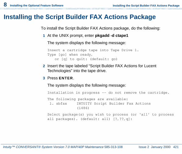
Intuity™ CONVERSANT® System Version 7.0 MAP/40P Maintenance 585-313-108 Issue 2 January 2000 421
8 Installing the Optional Feature Software
Installing the Script Builder FAX Actions Package
Installing the Script Builder FAX Actions Package
To install the Script Builder FAX Actions package, do the following:
1 At the UNIX prompt, enter pkgadd -d ctape1
The system displays the following message:
Insert a cartridge tape into Tape Drive 1.Type [go] when ready,
or [q] to quit: (default: go)
2 Insert the tape labeled “Script Builder FAX Actions for Lucent Technologies” into the tape drive.
3 Press ENTER.
The system displays the following message:
Installation in progress -- do not remove the cartridge.
The following packages are available: 1. sbfax INTUITY Script Builder Fax Actions
(i486)
Select package(s) you wish to process (or ‘all’ to process all packages). (default: all) [?,??,q]:
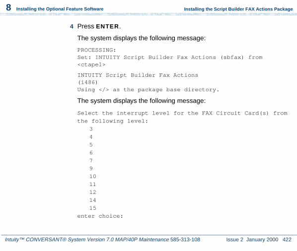
Intuity™ CONVERSANT® System Version 7.0 MAP/40P Maintenance 585-313-108 Issue 2 January 2000 422
8 Installing the Optional Feature Software
Installing the Script Builder FAX Actions Package
4 Press ENTER.
The system displays the following message:
PROCESSING:Set: INTUITY Script Builder Fax Actions (sbfax) from <ctape1>
INTUITY Script Builder Fax Actions(i486)Using </> as the package base directory.
The system displays the following message:
Select the interrupt level for the FAX Circuit Card(s) from
the following level:
3
4
5
6
7
9
10
11
12
14
15
enter choice:
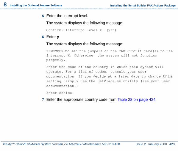
Intuity™ CONVERSANT® System Version 7.0 MAP/40P Maintenance 585-313-108 Issue 2 January 2000 423
8 Installing the Optional Feature Software
Installing the Script Builder FAX Actions Package
5 Enter the interrupt level.
The system displays the following message:
Confirm. Interrupt level X. (y/n)
6 Enter y
The system displays the following message:
REMEMBER to set the jumpers on the FAX circuit card(s) to use interrupt X. Otherwise, the system will not function properly.
Enter the code of the country in which this system will
operate. For a list of codes, consult your user
documentation. If you decide at a later date to change this setting, simply use the SetPlace.sb utility (see your user
documentation.)
Enter choice:
7 Enter the appropriate country code from Table 22 on page 424.

Intuity™ CONVERSANT® System Version 7.0 MAP/40P Maintenance 585-313-108 Issue 2 January 2000 424
8 Installing the Optional Feature Software
Installing the Script Builder FAX Actions Package
Table 22. Country Codes
Country: Code Country: Code Country: Code Country: Code
USA: 10 Canada: 11 Algeria: 2130 American Samoa: 6840
Andorra: 330 Argentina: 540 Australia: 610 Austria: 430
Barring: 9730 Belgium: 320 Belize: 5010 Bolivia: 5910
Brazil: 550 Cameroon: 2370 Chile: 560 Columbia: 570
Costa Rica: 5060 Cyprus: 3570 Czech Republic/Slovakia: 420
Denmark: 450
Ecuador: 5930 Egypt: 200 El Salvador: 5030 Ethiopia: 2510
Fiji: 6790 Finland: 3580 France: 330 French Antilles: 5960
French Antillis Guadeloupe: 5900
French Polynesia: 6890
Gabon: 2410 German Dem Rep: 370
German Fed Rep: 490
Greece: 300 Guam: 6710 Guantanamo Bay: 530
Guatemala: 5020 Guyana: 5920 Haiti: 5090 Honduras: 50401 of 3

Intuity™ CONVERSANT® System Version 7.0 MAP/40P Maintenance 585-313-108 Issue 2 January 2000 425
8 Installing the Optional Feature Software
Installing the Script Builder FAX Actions Package
Hong Kong: 8520 Hungary: 360 Iceland: 3540 India: 910
Indonesia: 620 Iran: 980 Iraq: 9640 Ireland: 3530
Israel: 9720 Italy (Co): 390 Italy (PBX): 391 Ivory Coast: 2250
Japan 10: 810 (10 pulse per second)
Japan 20: 811 (20 pulses per second)
Japan 10 DID: 812 (10 pulses per second)
Japan 2 DID: 813 (10 pulses per second)
Jordan: 9620 Kenya: 2540 Korea: 820 Kuwait: 9650
Liberia: 2310 Libya: 2180 Liechtenstein: 410 Luxembourg: 3520
Malawi: 2650 Malaysia: 600 Mexico: 520 Monaco: 330
Morocco: 2120 Namibia: 2640 Netherlands: 310 Netherlands Antilles: 5990
Netherlands Antilles Aruba: 2970
New Caledonia: 6870
New Zealand: 640 Nicaragua: 5050
Nigeria: 2340 Norway: 470 Norway X: 471 Oman: 9680
Table 22. Country Codes
Country: Code Country: Code Country: Code Country: Code
2 of 3

Intuity™ CONVERSANT® System Version 7.0 MAP/40P Maintenance 585-313-108 Issue 2 January 2000 426
8 Installing the Optional Feature Software
Installing the Script Builder FAX Actions Package
The system displays the following message:
Confirm. The country is X. (y/n)
Pakistan: 920 Panama: 5070 Papua New Guinea: 6750
Paraguay: 5950
Peru: 510 Philippines: 630 Poland: 480 Portugal: 3510
Qatar: 9740 Romania: 400 Saipan: 6700 San Marino: 390
Saudi Arabia: 9660
Senegal: 2210 Singapore: 650 South Africa: 270
Spain: 340 Sri Lanka: 940 Suriname: 5970 Sweden: 460
Switzerland: 410 Taiwan:8860 Thailand: 660 Tunisia: 2160
Turkey: 900 United Arab Emirates:9710
U.K. (CO): 440 U.K. (PBX): 441
Uruguay: 5980 Vatican City: 390 Venezuela: 580 Yemen ArabRepublic: 9670
Yugoslavia: 380
Table 22. Country Codes
Country: Code Country: Code Country: Code Country: Code
3 of 3

Intuity™ CONVERSANT® System Version 7.0 MAP/40P Maintenance 585-313-108 Issue 2 January 2000 427
8 Installing the Optional Feature Software
Installing the Script Builder FAX Actions Package
8 Enter y
The system displays the following message:
Enter the number of faxingDips you want running on your system. Your application will work fine regardless of how many you choose. If you decide at a later date to change this setting, simply use the SetFaxDip.sb utility (see your user documentation.)
! CAUTION:Using more than two faxingDips could cause your CPU idle time to be reduced to 0%. This will result in SPIO001 alarm messages and notification of the TSC.
For light expected FAX traffic enter 1For average expected FAX traffic enter 2For moderately heavy expected FAX traffic enter 3For heavy expected FAX traffic enter 4
enter choice:
9 Enter 1 or 2 as appropriate.
The system displays the following message:
Confirm. Number of faxingDips is X. (y/n)
10 Enter y

Intuity™ CONVERSANT® System Version 7.0 MAP/40P Maintenance 585-313-108 Issue 2 January 2000 428
8 Installing the Optional Feature Software
Installing the Script Builder FAX Actions Package
The system displays the following message:
If you currently have applications that use FAX Actions, re-verify and re-install them for best performance.
Your system will have X running faxingDips
The sbfax has been successfully installed. You must remove the last floppy disk. The system will reboot shortly.
The UNIX Operating System kernel will be rebuilt to include your configuration changes during the next system reboot.
Installation of INTUITY Script Builder Fax Actions (sbfax) was successful.
11 Enter q
12 Make sure that the light on the tape drive is off and remove the tape.
13 Reboot the system. See “Reboot the System,” in “Common System Procedures,” in the Intuity CONVERSANT System Reference, 585-313-205.
See the Intuity CONVERSANT Version 7.0 Application Development with Script Builder, 585-313-206, for more information on using Script Builder FAX Actions, as well as procedures to install the diskettes labeled “SBFAX_demo Backup Speech” and “Transmissions.”

Intuity™ CONVERSANT® System Version 7.0 MAP/40P Maintenance 585-313-108 Issue 2 January 2000 429
8 Installing the Optional Feature Software
Installing the Unix Management Screens Package
Installing the Unix Management Screens Package
To install the UNIX Management Screens Package, do the following:
1 At the UNIX prompt, enter pkgadd -d diskette1
The system displays the following message:
Insert diskette into Floppy Drive 1.Type [go] when ready,
or [q] to quit: (default: go)
2 Insert the diskette labeled “Unix Management Screens Package 1 of 1” into the diskette drive.
3 Press ENTER.
The system displays the following message:
Installation in progress -- do not remove the diskette.
The following packages are available: 1. unixmgmt INTUITY Unix Management Screens Package
(i486)
Select package(s) you wish to process (or ‘all’ to process all packages). (default: all) [?,??,q]:
4 Press ENTER.

Intuity™ CONVERSANT® System Version 7.0 MAP/40P Maintenance 585-313-108 Issue 2 January 2000 430
8 Installing the Optional Feature Software
Installing the Unix Management Screens Package
The system displays the following message:
PROCESSING:Set: INTUITY Unix Management Screens Package (unixmgmt) from <diskette1>
INTUITY Unix Management Screens Package(i486)Using </> as the package base directory.Lucent Technologies Inc.
The system displays several status messages and then the following message:
Installation of INTUITY Unix Management Screens Package (unixmgmt) was successful.
Insert diskette into Floppy Drive 1.Type [go] when ready,
or [q] to quit: (default: go)
5 Enter q
The system displays the UNIX prompt.
6 Make sure that the light on the diskette drive is off and remove the diskette.

Intuity™ CONVERSANT® System Version 7.0 MAP/40P Maintenance 585-313-108 Issue 2 January 2000 431
8 Installing the Optional Feature Software
Installing T1 Packages
Installing T1 Packages
The T1 packages include:
• Line side T1 interface packages
• T1 E&M package
Installing the Line Side T1 Interface Packages
The line side T1 interface packages are separated by the type of switch to which they will interface. Procedures for the following packages are available:
• Installing the Line Side T1 Interface Package - Definity on page 431
• Installing the Line Side T1 Interface Package - Galaxy on page 434
Installing the Line Side T1 Interface Package - Definity
To install the Line Side T1 Interface Package — Definity, do the following:
1 If you are not already logged in as root, do so now.
2 Ensure that the T1 driver package has been installed.

Intuity™ CONVERSANT® System Version 7.0 MAP/40P Maintenance 585-313-108 Issue 2 January 2000 432
8 Installing the Optional Feature Software
Installing T1 Packages
3 Enter pkgadd -d diskette1
The system displays the following message:
Insert diskette into Floppy Drive 1.Type [go] when ready,
or [q] to quit: (default: go)
4 Insert the diskette labeled “Line Side T1 Package - Definity 1 of 2” into the diskette drive.
5 Press ENTER.
The system displays the following message:
Installation in progress -- do not remove the diskette.
The following packages are available: 1. lst1d INTUITY Line Side T1 Package - Definity
(i486)
Select package(s) you wish to process (or ‘all’ to process all packages). (default: all) [?,??,q]:
6 Press ENTER.
The system displays the following message:
PROCESSING:Set: INTUITY Line Side T1 Package - Definity (lst1d) from <diskette1>

Intuity™ CONVERSANT® System Version 7.0 MAP/40P Maintenance 585-313-108 Issue 2 January 2000 433
8 Installing the Optional Feature Software
Installing T1 Packages
INTUITY Line Side T1 Package - Definity(i486)Using </> as the package base directory.Lucent Technologies Inc.
The system displays several status messages and then the following message:
READY TO PROCESS:
Package: INTUITY Line Side T1 Package - Definity
(lst1d) diskette 2 of 2
Insert diskette 2 of 2 into Floppy Drive 1.Type [go] when ready,
or [q] to quit: (default: go)
7 Remove the diskette labeled “Line Side T1 Package - Definity 1 of 2” from the diskette drive.
8 Insert the diskette labeled “Line Side T1 Package - Definity 2 of 2” into the diskette drive.
9 Press ENTER.
The system displays several status messages and then the following message:
This concludes the steps required to install the ‘Line Side T1 - Definity’ feature. However, additional steps are required to activate the feature. Consult the INTUITY VIS
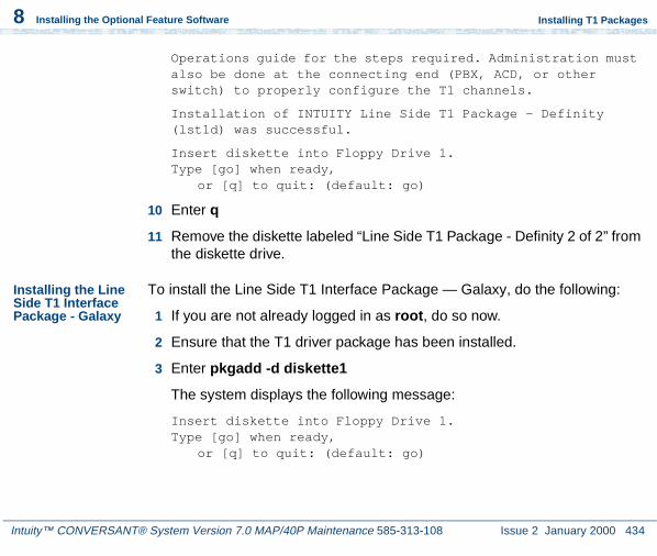
Intuity™ CONVERSANT® System Version 7.0 MAP/40P Maintenance 585-313-108 Issue 2 January 2000 434
8 Installing the Optional Feature Software
Installing T1 Packages
Operations guide for the steps required. Administration must also be done at the connecting end (PBX, ACD, or other switch) to properly configure the T1 channels.
Installation of INTUITY Line Side T1 Package - Definity (lst1d) was successful.
Insert diskette into Floppy Drive 1.Type [go] when ready,
or [q] to quit: (default: go)
10 Enter q
11 Remove the diskette labeled “Line Side T1 Package - Definity 2 of 2” from the diskette drive.
Installing the Line Side T1 Interface Package - Galaxy
To install the Line Side T1 Interface Package — Galaxy, do the following:
1 If you are not already logged in as root, do so now.
2 Ensure that the T1 driver package has been installed.
3 Enter pkgadd -d diskette1
The system displays the following message:
Insert diskette into Floppy Drive 1.Type [go] when ready,
or [q] to quit: (default: go)

Intuity™ CONVERSANT® System Version 7.0 MAP/40P Maintenance 585-313-108 Issue 2 January 2000 435
8 Installing the Optional Feature Software
Installing T1 Packages
4 Insert the diskette labeled “Line Side T1 Package - Galaxy 1 of 1” into the diskette drive.
5 Press ENTER.
The system displays the following message:
Installation in progress -- do not remove the diskette.
The following packages are available: 1. lst1g INTUITY Line Side T1 Package - Galaxy
(i486)
Select package(s) you wish to process (or ‘all’ to process all packages). (default: all) [?,??,q]:
6 Press ENTER.
The system displays the following message:
PROCESSING:Set: INTUITY Line Side T1 Package - Galaxy (lst1g) from <diskette1>
INTUITY Line Side T1 Package - Galaxy(i486)Using </> as the package base directory.Lucent Technologies Inc.

Intuity™ CONVERSANT® System Version 7.0 MAP/40P Maintenance 585-313-108 Issue 2 January 2000 436
8 Installing the Optional Feature Software
Installing T1 Packages
The system displays several status messages and then the following message:
This concludes the steps required to install the ‘Line Side T1 - Galaxy’ feature. However, additional steps are required to activate the feature. Consult the INTUITY VIS Operations guide for the steps required. Administration must also be done at the connecting end (PBX, ACD, or other switch) to properly configure the T1 channels.
Installation of INTUITY Line Side T1 Package - Galaxy (lst1g) was successful.
Insert diskette into Floppy Drive 1.Type [go] when ready,
or [q] to quit: (default: go)
7 Enter q
8 Remove the diskette labeled “Line Side T1 Package - Galaxy 1 of 1” from the diskette drive.
Installing the T1 E&M Package
To install the T1 E&M package, do the following:
1 If you are not already logged in as root, do so now.
2 Ensure that the T1 driver package has been installed.

Intuity™ CONVERSANT® System Version 7.0 MAP/40P Maintenance 585-313-108 Issue 2 January 2000 437
8 Installing the Optional Feature Software
Installing T1 Packages
3 Enter pkgadd -d diskette1
The system displays the following message:
Insert diskette into Floppy Drive 1.Type [go] when ready,
or [q] to quit: (default: go)
4 Insert the diskette labeled “T1 E&M Package 1 of 1” into the diskette drive.
5 Press ENTER.
The system displays the following message:
Installation in progress -- do not remove the diskette.
The following packages are available: 1. t1em INTUITY T1 E&M Interface Package
(i486)
Select package(s) you wish to process (or ‘all’ to process all packages). (default: all) [?,??,q]:
6 Press ENTER.
The system displays the following message:
PROCESSING:Set: INTUITY T1 E&M Interface Package (t1em) from <diskette1>

Intuity™ CONVERSANT® System Version 7.0 MAP/40P Maintenance 585-313-108 Issue 2 January 2000 438
8 Installing the Optional Feature Software
Installing T1 Packages
INTUITY T1 E&M Interface Package(i486)Using </> as the package base directory.Lucent Technologies Inc.
The system displays several status messages and then the following message:
This concludes the steps required to install the ‘T1 E&M Interface Package’ feature. However, additional steps are required to activate the feature. Consult the INTUITY VIS Operations guide for the steps required. Administration must also be done at the connecting end (PBX, ACD, or other switch) to properly configure the T1 channels.
Installation of INTUITY T1 E&M Interface Package (t1em) was successful.
Insert diskette into Floppy Drive 1.Type [go] when ready,
or [q] to quit: (default: go)
7 Enter q
8 Remove the diskette labeled “T1 E&M Package 1 of 1” from the diskette drive.

Intuity™ CONVERSANT® System Version 7.0 MAP/40P Maintenance 585-313-108 Issue 2 January 2000 439
8 Installing the Optional Feature Software
Installing the Text To Speech Package
Installing the Text To Speech Package
Note: If you are installing the TTS package and feature_tst is already installed on your system (as in assisted upgrades), once you have finished installing all other desired, you must remove feature_tst and reinstall it in order to select the TTS test.
To install the TTS package, do the following:
1 If you are not already logged in as root, do so now.
2 Enter pkgadd -d diskette1
The system displays the following message:
Insert diskette into Floppy Drive 1.Type [go] when ready,
or [q] to quit: (default: go)
3 Insert the diskette labeled “Text to Speech Package 1 of 8” into the diskette drive.
4 Press ENTER.
The system displays the following message:
Installation in progress -- do not remove the diskette.
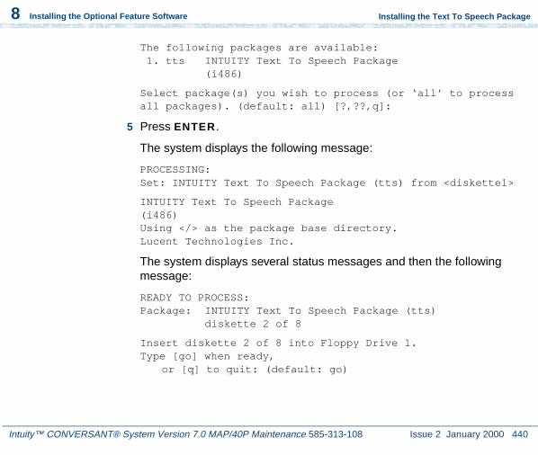
Intuity™ CONVERSANT® System Version 7.0 MAP/40P Maintenance 585-313-108 Issue 2 January 2000 440
8 Installing the Optional Feature Software
Installing the Text To Speech Package
The following packages are available: 1. tts INTUITY Text To Speech Package
(i486)
Select package(s) you wish to process (or ‘all’ to process all packages). (default: all) [?,??,q]:
5 Press ENTER.
The system displays the following message:
PROCESSING:Set: INTUITY Text To Speech Package (tts) from <diskette1>
INTUITY Text To Speech Package(i486)Using </> as the package base directory.Lucent Technologies Inc.
The system displays several status messages and then the following message:
READY TO PROCESS:Package: INTUITY Text To Speech Package (tts)
diskette 2 of 8
Insert diskette 2 of 8 into Floppy Drive 1.Type [go] when ready,
or [q] to quit: (default: go)

Intuity™ CONVERSANT® System Version 7.0 MAP/40P Maintenance 585-313-108 Issue 2 January 2000 441
8 Installing the Optional Feature Software
Installing the Text To Speech Package
6 Remove the diskette labeled “Text to Speech Package 1 of 8” from the diskette drive.
7 Insert the diskette labeled “Text to Speech Package 2 of 8” into the diskette drive.
8 Press ENTER.
The system displays several status messages and then the following message:
READY TO PROCESS:Package: INTUITY Text To Speech Package (tts)
diskette 3 of 8
Insert diskette 3 of 8 into Floppy Drive 1.Type [go] when ready,
or [q] to quit: (default: go)
9 Remove the diskette labeled “Text to Speech Package 2 of 8” from the diskette drive.
10 Insert the diskette labeled “Text to Speech Package 3 of 8” into the diskette drive.

Intuity™ CONVERSANT® System Version 7.0 MAP/40P Maintenance 585-313-108 Issue 2 January 2000 442
8 Installing the Optional Feature Software
Installing the Text To Speech Package
11 Press ENTER.
The system displays several status messages and then the following message:
READY TO PROCESS:Package: INTUITY Text To Speech Package (tts)
diskette 4 of 8
Insert diskette 4 of 8 into Floppy Drive 1.Type [go] when ready,
or [q] to quit: (default: go)
12 Remove the diskette labeled “Text to Speech Package 3 of 8” from the diskette drive.
13 Insert the diskette labeled “Text to Speech Package 4 of 8” into the diskette drive.
14 Press ENTER.
The system displays several status messages and then the following message:
READY TO PROCESS:Package: INTUITY Text To Speech Package (tts)
diskette 5 of 8
Insert diskette 5 of 8 into Floppy Drive 1.Type [go] when ready,
or [q] to quit: (default: go)

Intuity™ CONVERSANT® System Version 7.0 MAP/40P Maintenance 585-313-108 Issue 2 January 2000 443
8 Installing the Optional Feature Software
Installing the Text To Speech Package
15 Remove the diskette labeled “Text to Speech Package 4 of 8” from the diskette drive.
16 Insert the diskette labeled “Text to Speech Package 5 of 8” into the diskette drive.
17 Press ENTER.
The system displays several status messages and then the following message:
READY TO PROCESS:Package: INTUITY Text To Speech Package (tts)
diskette 6 of 8
Insert diskette 6 of 8 into Floppy Drive 1.Type [go] when ready,
or [q] to quit: (default: go)
18 Remove the diskette labeled “Text to Speech Package 5 of 8” from the diskette drive.
19 Insert the diskette labeled “Text to Speech Package 6 of 8” into the diskette drive.
20 Press ENTER.

Intuity™ CONVERSANT® System Version 7.0 MAP/40P Maintenance 585-313-108 Issue 2 January 2000 444
8 Installing the Optional Feature Software
Installing the Text To Speech Package
The system displays several status messages and then the following message:
READY TO PROCESS:Package: INTUITY Text To Speech Package (tts)
diskette 7 of 8
Insert diskette 7 of 8 into Floppy Drive 1.Type [go] when ready,
or [q] to quit: (default: go)
21 Remove the diskette labeled “Text to Speech Package 6 of 8” from the diskette drive.
22 Insert the diskette labeled “Text to Speech Package 7 of 8” into the diskette drive.
23 Press ENTER.
The system displays several status messages and then the following message:
READY TO PROCESS:Package: INTUITY Text To Speech Package (tts)
diskette 8 of 8
Insert diskette 8 of 8 into Floppy Drive 1.Type [go] when ready,
or [q] to quit: (default: go)

Intuity™ CONVERSANT® System Version 7.0 MAP/40P Maintenance 585-313-108 Issue 2 January 2000 445
8 Installing the Optional Feature Software
Installing the Text To Speech Package
24 Remove the diskette labeled “Text to Speech Package 7 of 8” from the diskette drive.
25 Insert the diskette labeled “Text to Speech Package 8 of 8” into the diskette drive.
26 Press ENTER.
The system displays several status messages and then the following message:
Installation of Text To Speech Package (tts) was successful.
Insert diskette into Floppy Drive 1.Type [go] when ready,
or [q] to quit: (default: go)
27 Enter q
28 Remove the diskette labeled “Text to Speech Package 8 of 8” from the diskette drive.
For more information on this feature package, see Intuity CONVERSANT Version 7.0 Speech Development, Processing, and Recognition, 585-313-201.

Intuity™ CONVERSANT® System Version 7.0 MAP/40P Maintenance 585-313-108 Issue 2 January 2000 446
8 Installing the Optional Feature Software
Installing the WholeWord Recognition Packages
Installing the WholeWord Recognition Packages
Procedures to install the WholeWord recognition packages include:
• Installing the WholeWord Recognition Base Package on page 446
• Installing the WholeWord Recognition Language Package on page 448
Installing the WholeWord Recognition Base Package
Note: If you are installing the WholeWord Recognition Base package and feature_tst is already installed on your system (as in assisted upgrades), once you have finished installing all other desired, you must remove feature_tst and reinstall it in order to select the ASR test.
To install the WholeWord Recognition Base package, do the following:
1 If you are not already logged in as root, do so now.
2 Enter pkgadd -d diskette1
The system displays the following message:
Insert diskette into Floppy Drive 1.Type [go] when ready,
or [q] to quit: (default: go)

Intuity™ CONVERSANT® System Version 7.0 MAP/40P Maintenance 585-313-108 Issue 2 January 2000 447
8 Installing the Optional Feature Software
Installing the WholeWord Recognition Packages
3 Insert the diskette labeled “WholeWord Recognition - Base 1 of 1” into the diskette drive.
4 Press ENTER.
The system displays the following message:
Installation in progress -- do not remove the diskette.
The following packages are available: 1. asr INTUITY WholeWord Recognition - Base
(i486)
Select package(s) you wish to process (or ‘all’ to process all packages). (default: all) [?,??,q]:
5 Press ENTER.
The system displays the following message:
PROCESSING:Set: INTUITY WholeWord Recognition - Base (asr) from <diskette1>
INTUITY WholeWord Recognition - Base(i486)Using </> as the package base directory.Lucent Technologies Inc.

Intuity™ CONVERSANT® System Version 7.0 MAP/40P Maintenance 585-313-108 Issue 2 January 2000 448
8 Installing the Optional Feature Software
Installing the WholeWord Recognition Packages
The system displays several status messages and then the following message:
Installation of INTUITY WholeWord Recognition - Base (asr) was successful.
Insert diskette into Floppy Drive 1.Type [go] when ready,
or [q] to quit: (default: go)
6 Enter q
7 Remove the diskette labeled “WholeWord Recognition - Base 1 of 1” from the diskette drive.
Installing the WholeWord Recognition Language Package
To install the WholeWord Recognition Language package, do the following:
1 If you are not already logged in as root, do so now.
2 Enter pkgadd -d diskette1
The system displays the following message:
Insert diskette into Floppy Drive 1.Type [go] when ready,
or [q] to quit: (default: go)

Intuity™ CONVERSANT® System Version 7.0 MAP/40P Maintenance 585-313-108 Issue 2 January 2000 449
8 Installing the Optional Feature Software
Installing the WholeWord Recognition Packages
3 Insert the diskette labeled “WholeWord Recognition - Language 1 of 1” into the diskette drive.
4 Press ENTER.
The system displays the following message:
Installation in progress -- do not remove the diskette.
The following packages are available: 1. usrecog INTUITY WholeWord Recognition - US
English (i486)
Select package(s) you wish to process (or ‘all’ to process all packages). (default: all) [?,??,q]:
5 Press ENTER.
The system displays the following message:
PROCESSING:Set: INTUITY WholeWord Recognition - US English (usrecog) from <diskette1>
INTUITY WholeWord Recognition - US English(i486)Using </> as the package base directory.Lucent Technologies Inc.

Intuity™ CONVERSANT® System Version 7.0 MAP/40P Maintenance 585-313-108 Issue 2 January 2000 450
8 Installing the Optional Feature Software
Installing the Feature Test Script Package
The system displays several status messages and then the following message:
Installation of INTUITY WholeWord Recognition - US English (usrecog) was successful.
Insert diskette into Floppy Drive 1.Type [go] when ready,
or [q] to quit: (default: go)
6 Enter q
7 Remove the diskette labeled “WholeWord Recognition - Language 1 of 1” from the diskette drive.
For more information on this feature package, see Intuity CONVERSANT Version 7.0 Speech Development, Processing, and Recognition, 585-313-201.
Installing the Feature Test Script Package
Use the following procedure to install this optional feature package only after all the other optional feature packages have been installed:
1 The voice system must be running. To see if the system is running, use the who -r command.

Intuity™ CONVERSANT® System Version 7.0 MAP/40P Maintenance 585-313-108 Issue 2 January 2000 451
8 Installing the Optional Feature Software
Installing the Feature Test Script Package
The voice system is running if the run-level is 4. If the system is not running, execute the start_vs command.
2 Enter pkgadd -d diskette1
The system displays the following message:
Insert diskette into Floppy Drive 1.Type [go] when ready,
or [q] to quit: (default: go)
3 Insert the diskette labeled “Feature Test Script Package 1 of 3” into the diskette drive.
4 Press ENTER.
The system displays the following message:
Installation in progress -- do not remove the diskette.
The following packages are available: 1. ftst INTUITY Feature Test Script Package
(i486)
Select package(s) you wish to process (or ‘all’ to process all packages). (default: all) [?,??,q]:
5 Press ENTER.
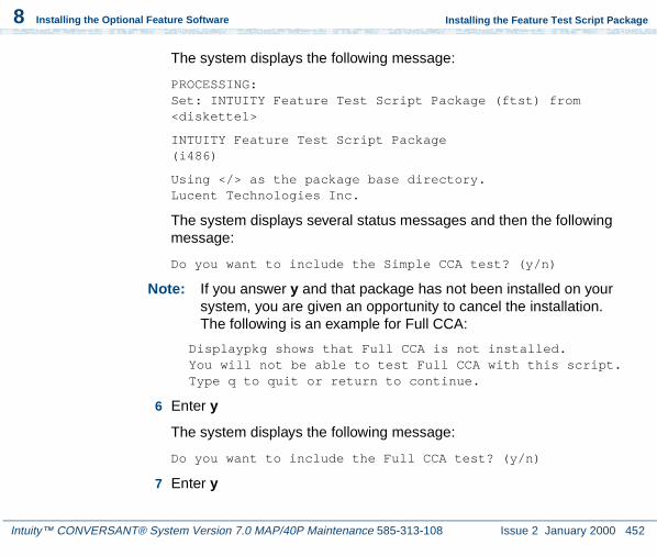
Intuity™ CONVERSANT® System Version 7.0 MAP/40P Maintenance 585-313-108 Issue 2 January 2000 452
8 Installing the Optional Feature Software
Installing the Feature Test Script Package
The system displays the following message:
PROCESSING:Set: INTUITY Feature Test Script Package (ftst) from <diskette1>
INTUITY Feature Test Script Package(i486)
Using </> as the package base directory.Lucent Technologies Inc.
The system displays several status messages and then the following message:
Do you want to include the Simple CCA test? (y/n)
Note: If you answer y and that package has not been installed on your system, you are given an opportunity to cancel the installation. The following is an example for Full CCA:
Displaypkg shows that Full CCA is not installed.You will not be able to test Full CCA with this script.Type q to quit or return to continue.
6 Enter y
The system displays the following message:
Do you want to include the Full CCA test? (y/n)
7 Enter y

Intuity™ CONVERSANT® System Version 7.0 MAP/40P Maintenance 585-313-108 Issue 2 January 2000 453
8 Installing the Optional Feature Software
Installing the Feature Test Script Package
The system displays the following message:
Do you want to include the Playback and Coding test? (y/n)
8 Enter y
The system displays the following message:
Do you want to include the Chantst test? (y/n)
9 Enter y
The system displays the following message:
Do you want to include the Transfer Test test? (y/n)
10 Enter y
The system displays the following message:
Do you want to include the Dial Pulse Recognition test? (y/n)
11 Enter y
The system displays the following message:
READY TO PROCESS:Package: INTUITY Feature Test Script Package (ftst) diskette 2 of 3
Insert diskette 2 of 3 into Floppy Drive 1.Type [go] when ready,or [q] to quit: (default: go)

Intuity™ CONVERSANT® System Version 7.0 MAP/40P Maintenance 585-313-108 Issue 2 January 2000 454
8 Installing the Optional Feature Software
Installing the Feature Test Script Package
Do you want to include the Speech Recognition test? (y/n)
12 Remove the diskette labeled “Feature Test Script Package 1 of 3” from the diskette drive.
13 Insert the diskette labeled “Feature Test Script Package 2 of 3” into the diskette drive.
14 Press ENTER.
The system displays several status messages and then the following message:
READY TO PROCESS:Package: INTUITY Feature Test Script Package (ftst) diskette 3 of 3
Insert diskette 3 of 3 into Floppy Drive 1.Type [go] when ready,
or [q] to quit: (default: go)
15 Remove the diskette labeled “Feature Test Script Package 2 of 3” from the diskette drive.
16 Insert the diskette labeled “Feature Test Script Package 3 of 3” into the diskette drive.
17 Press ENTER.
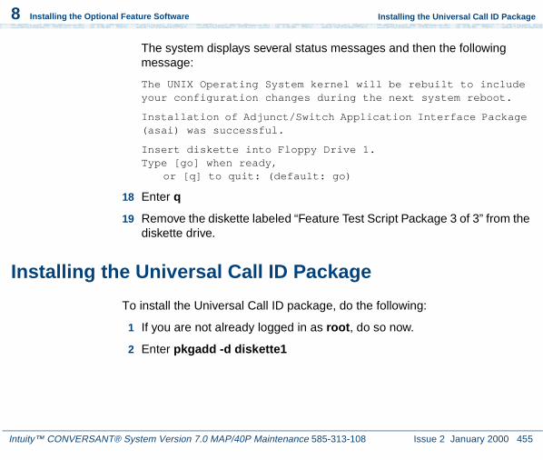
Intuity™ CONVERSANT® System Version 7.0 MAP/40P Maintenance 585-313-108 Issue 2 January 2000 455
8 Installing the Optional Feature Software
Installing the Universal Call ID Package
The system displays several status messages and then the following message:
The UNIX Operating System kernel will be rebuilt to include your configuration changes during the next system reboot.
Installation of Adjunct/Switch Application Interface Package (asai) was successful.
Insert diskette into Floppy Drive 1.Type [go] when ready,
or [q] to quit: (default: go)
18 Enter q
19 Remove the diskette labeled “Feature Test Script Package 3 of 3” from the diskette drive.
Installing the Universal Call ID Package
To install the Universal Call ID package, do the following:
1 If you are not already logged in as root, do so now.
2 Enter pkgadd -d diskette1

Intuity™ CONVERSANT® System Version 7.0 MAP/40P Maintenance 585-313-108 Issue 2 January 2000 456
8 Installing the Optional Feature Software
Installing the Universal Call ID Package
The system displays the following message:
Insert a diskette into Floppy Drive 1.Type [go] when ready,
or [q] to quit: (default: go)
3 Insert the diskette labeled “Universal Call ID Package 1 of 1” into the diskette drive.
4 Press ENTER.
The system displays the following message:
Installation in progress. Do not remove the diskette.
The following packages are available:
1.ucid INTUITY Universal Call ID(i486)
Select package(s) you wish to process (or ‘all’ to process all packages). (default: all) [?,??,q]:
5 Press ENTER.
The system displays the following message:
PROCESSING:Set: INTUITY Universal Call ID Package (ucid) from <diskette1>
INTUITY Universal Call ID Package (i486)

Intuity™ CONVERSANT® System Version 7.0 MAP/40P Maintenance 585-313-108 Issue 2 January 2000 457
8 Installing the Optional Feature Software
Installing the SNMP Emanate Agent Package
Using </> as the package base directory.Lucent Technologies Inc.
The system displays several status messages and then the following message:
Installation of INTUITY Universal Call ID (ucid) was successful
Insert a diskette into Floppy Drive 1.Type [go] when ready,
or [q] to quit: (default: go)
6 Enter q
The system displays the Console Login prompt.
7 Remove the diskette labeled “Universal Call ID Package” from the diskette drive.
In order to activate this feature, you must specify the UCID Network Node ID. See Chapter 4, “Feature Package Administration,” of Intuity CONVERSANT System Version 7.0 Administration, 585-313-501.
Installing the SNMP Emanate Agent Package
To install the SNMP Emanate Agent package, do the following:
1 If you are not already logged in as root, do so now.

Intuity™ CONVERSANT® System Version 7.0 MAP/40P Maintenance 585-313-108 Issue 2 January 2000 458
8 Installing the Optional Feature Software
Installing the SNMP Emanate Agent Package
2 Enter pkgadd -d diskette1
The system displays the following message:
Insert a diskette into Floppy Drive 1.Type [go] when ready,
or [q] to quit: (default: go)
3 Insert the diskette labeled “Intuity SNMP Emanate Agent” into the diskette drive.
4 Press ENTER.
The system displays the following message:
Installation in progress. Do not remove the diskette.
The following packages are available:
1.snmp INTUITY SNMP Emanate Agent (snmp)(i486)
Select package(s) you wish to process (or ‘all’ to process all packages). (default: all) [?,??,q]:
5 Press ENTER.
The system displays the following message:
PROCESSING:Set: INTUITY SNMP Emanate Agent (snmp) from <diskette1>

Intuity™ CONVERSANT® System Version 7.0 MAP/40P Maintenance 585-313-108 Issue 2 January 2000 459
8 Installing the Optional Feature Software
Removing Software Packages
INTUITY Emanate Agent(i486) i.3.1
Using </> as the package base directory.
The system displays several status messages and then the following message:
Installation of INTUITY SNMP Emanate Agent (snmp) was successful
Insert a diskette into Floppy Drive 1.Type [go] when ready,
or [q] to quit: (default: go)
6 Enter q
The system displays the Console Login prompt.
7 Remove the diskette labeled “Intuity SNMP Emanate Agent” from the diskette drive.
Removing Software Packages
Software packages can be removed using:
• The command line
• The Intuity CONVERSANT screens

Intuity™ CONVERSANT® System Version 7.0 MAP/40P Maintenance 585-313-108 Issue 2 January 2000 460
8 Installing the Optional Feature Software
Removing Software Packages
Using the Command Line
Use the removepkg or pkgrm commands to remove a software package from your system. See Intuity CONVERSANT Version 7.0 Administration, 585-313-501, book for more information on these commands.
There are some important issues you need to be aware of when removing software from your system:
• Remove all services, functions, or card assignments before removing any software packages.
• When removing the Application software, you are asked if you want to remove speech file systems. Answer no to this prompt.
• During an initial installation of the Base ORACLE RDBMS package, a user called “oracle” is created. This user is NOT removed when the Base ORACLE RDBMS package is removed. Once all the base and add-on ORACLE packages have been removed, if you want to remove the “oracle” user, do so through SYSADM. See Appendix A, “System Administration Features,” in Intuity CONVERSANT Version 7.0 Administration, 585-313-501.
To remove software packages, do the following:
1 Enter displaypkg at the system prompt #.
The system displays all the packages installed on your system.

Intuity™ CONVERSANT® System Version 7.0 MAP/40P Maintenance 585-313-108 Issue 2 January 2000 461
8 Installing the Optional Feature Software
Removing Software Packages
2 Once you have determined the packages to be removed, enter removepkg or pkgrmAt the prompt, enter the number (as it appears on the screen) beside the package you want to remove.
Repeat Step 2 for each package you want to remove.
! CAUTION:After you have removed packages from a UnixWare system, you MUST reboot the system before reinstalling packages. You can remove more than one package before rebooting, but you must reboot before reinstalling any packages.

Intuity™ CONVERSANT® System Version 7.0 MAP/40P Maintenance 585-313-108 Issue 2 January 2000 462
8 Installing the Optional Feature Software
Removing Software Packages
Using the Intuity CONVERSANT Screens
Note: Your system must have the Unix Management Screens Package installed in order to use this procedure.
To remove software using the Intuity CONVERSANT screens, do the following:
1 Starting at the Voice System Administration menu (Figure 110 on page 308), select
The system displays the Software Remove screen (Figure 116 on page 463). which lists the software installed on the system.
>Software Remove
> UNIX Management

Intuity™ CONVERSANT® System Version 7.0 MAP/40P Maintenance 585-313-108 Issue 2 January 2000 463
8 Installing the Optional Feature Software
Removing Software Packages
Figure 116. Software Remove Screen
2 Locate the package you wish to remove.
3 Note the number of the package given in the first column.
4 Press CTRL + D.
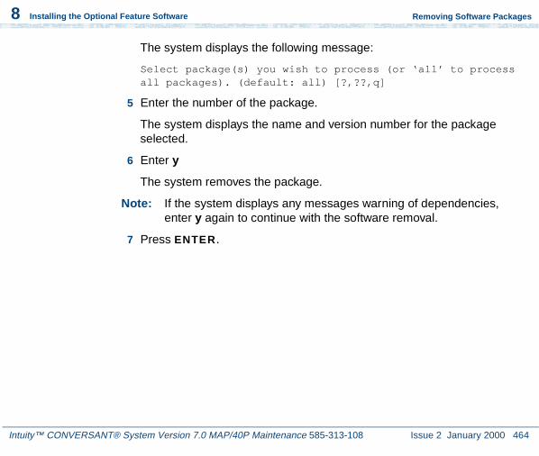
Intuity™ CONVERSANT® System Version 7.0 MAP/40P Maintenance 585-313-108 Issue 2 January 2000 464
8 Installing the Optional Feature Software
Removing Software Packages
The system displays the following message:
Select package(s) you wish to process (or ‘all’ to process all packages). (default: all) [?,??,q]
5 Enter the number of the package.
The system displays the name and version number for the package selected.
6 Enter y
The system removes the package.
Note: If the system displays any messages warning of dependencies, enter y again to continue with the software removal.
7 Press ENTER.

Intuity™ CONVERSANT® System Version 7.0 MAP/40P Maintenance 585-313-108 Issue 2 January 2000 465
A System Configuration
Overview
This appendix describes the placement of components in the MAP/40P and the operation of the Hardware Resource Allocator.
The information is designed to enable technicians to reconfigure the Intuity CONVERSANT system when it is necessary to add or remove hardware.
Topics covered include:
• Component Assignments on page 466
• Operating the Hardware Resource Allocator on page 468
• Configuration Device Data on page 492

A System Configuration Component Assignments
Intuity™ CONVERSANT® System Version 7.0 MAP/40P Maintenance 585-313-108 Issue 2 January 2000 466
Component Assignments
Circuit cards are placed in the MAP/40P in locations called slots. Slots are numbered ISA1 through ISA 10 and PCI 1 through PCI 3 from the bottom of the MAP/40P to the top of the card cage. Slots are accessible from the back of the MAP/40P (Figure 117 on page 467).
Table 23 on page 466 lists the SCSI IDs for the components installed for the Intuity CONVERSANT system.
Table 23. MAP/40P Resource Locations
Device SCSI ID
Primary hard disk drive 0
Secondary hard disk drive (if present) 1
Tape drive 3
Diskette drive N/A

A System Configuration Component Assignments
Intuity™ CONVERSANT® System Version 7.0 MAP/40P Maintenance 585-313-108 Issue 2 January 2000 467
Figure 117. Back View of the MAP/40P
h2mxrear KLC 081997
1
2
3
4
6
7
8
9
10
5
1. AC power inlet receptacle
2. AC power supply outlet
3. External SCSI I/O connector
4. Parallel port
5. COM2
6. Keyboard connector
7. Power supply fan exhaust
8. Mouse connector
9. Video connector
10.COM1

A System Configuration Operating the Hardware Resource Allocator
Intuity™ CONVERSANT® System Version 7.0 MAP/40P Maintenance 585-313-108 Issue 2 January 2000 468
Operating the Hardware Resource Allocator
Operation of the Hardware Resource Allocator includes the following tasks:
• Adding Hardware to an Existing Configuration on page 468
• Removing Hardware from an Existing Configuration on page 473
• Specifying a New Configuration on page 477
• Saving a Configuration on page 482
• Viewing a Configuration on page 484
• Comparing a Configuration on page 489
• Presetting Hardware Resources on page 489
Adding Hardware to an Existing Configuration
When you modify an existing configuration, you may have to change the current resource assignments:
• Differences in slot assignments or serial/parallel port assignments will not require switch settings and/or driver software changes. However, you may need to rearrange the cards and/or cables to fit the new configuration output.

A System Configuration Operating the Hardware Resource Allocator
Intuity™ CONVERSANT® System Version 7.0 MAP/40P Maintenance 585-313-108 Issue 2 January 2000 469
• Differences in INTR, DMAC, IOADDR, or RAMADDR assignments will in most cases require you to change switch settings and reinstall driver software for the affected cards.
To add hardware to an existing configuration, do the following:
1 Enter get_config
The system displays the following message:
This program retrieves the /vs/data/confData file for a given VIS machine from floppy disk. This file represents the configuration of the machine and is required in order for the /vs/bin/util/configure program to upgrade the machine with new or additional hardware.
Please insert the "CONFIGURATION DATA" floppy for this machine.
Press <Enter> when ready to proceed...
2 Insert the diskette labeled "Configuration Data" into the diskette drive.
3 Press ENTER.
The system displays the following message:
Working.../vs/data/confData retrieved
UNIX_SV#

A System Configuration Operating the Hardware Resource Allocator
Intuity™ CONVERSANT® System Version 7.0 MAP/40P Maintenance 585-313-108 Issue 2 January 2000 470
4 Make a hard copy of the current configuration by printing the output of the show_config command. See Viewing a Configuration on page 484 for an explanation of the show_config command.
5 Enter configure
The system displays the following message:
A configuration file, confData, exits.Do you wish to make changes to the previous configuration [y|n]?
6 Enter y
The system displays the following message:
Reading old configuration. Please wait...
Successfully read MAP/40P Platform with PCI backplane and P5 200 CPU.
Adding device ADAPSCSIAdding device VIDEOAdding device SCSIHDAdding device SCSITAPE
Press any key to continue...
Note: This message depends on your system configuration and may look different than the one shown.
7 Press ENTER.
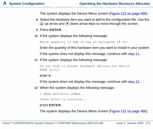
A System Configuration Operating the Hardware Resource Allocator
Intuity™ CONVERSANT® System Version 7.0 MAP/40P Maintenance 585-313-108 Issue 2 January 2000 471
The system displays the Device Menu screen (Figure 122 on page 480).
8 Select the hardware item you want to add to the configuration file. Use the up arrow and down arrow keys to move through the screen.
9 Press ENTER.
10 If the system displays the following message:
Enter quantity to add (X max in multiples of 1):
Enter the quantity of this hardware item you want to install in your system.
If the system does not display this message, continue with step 11.
11 If the system displays the following message:
Do you wish to preset hardware options for device XXXX [y|n]?
enter n
If the system does not display this message, continue with step 12.
12 When the system displays the following message:
1 XXXX device(s) added.
Press Enter to continue...
press ENTER .
The system displays the Device Menu screen (Figure 122 on page 480).

A System Configuration Operating the Hardware Resource Allocator
Intuity™ CONVERSANT® System Version 7.0 MAP/40P Maintenance 585-313-108 Issue 2 January 2000 472
13 When you are done adding hardware to the configuration press d
The system displays the following message:
Configuration complete and successful.Configuration data written to file: /vs/data/confData.
14 View the new configuration file to make sure you have added the correct hardware. See Viewing a Configuration on page 484 for the procedure.
15 Make the necessary adjustments on the installed hardware based on the new configuration.
16 Save the new configuration. See Saving a Configuration on page 482 for the procedure.
17 Enter hconchk
The system displays the following message:
hconchk: The hardware configuration check is complete.
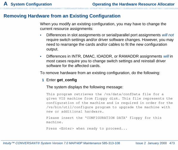
A System Configuration Operating the Hardware Resource Allocator
Intuity™ CONVERSANT® System Version 7.0 MAP/40P Maintenance 585-313-108 Issue 2 January 2000 473
Removing Hardware from an Existing Configuration
When you modify an existing configuration, you may have to change the current resource assignments:
• Differences in slot assignments or serial/parallel port assignments will not require switch settings and/or driver software changes. However, you may need to rearrange the cards and/or cables to fit the new configuration output.
• Differences in INTR, DMAC, IOADDR, or RAMADDR assignments will in most cases require you to change switch settings and reinstall driver software for the affected cards.
To remove hardware from an existing configuration, do the following:
1 Enter get_config
The system displays the following message:
This program retrieves the /vs/data/confData file for a given VIS machine from floppy disk. This file represents the configuration of the machine and is required in order for the /vs/bin/util/configure program to upgrade the machine with new or additional hardware.
Please insert the "CONFIGURATION DATA" floppy for this machine.
Press <Enter> when ready to proceed...

A System Configuration Operating the Hardware Resource Allocator
Intuity™ CONVERSANT® System Version 7.0 MAP/40P Maintenance 585-313-108 Issue 2 January 2000 474
2 Insert the diskette labelled "Configuration Data" into the diskette drive.
3 Press ENTER.
The system displays the following message:
Working.../vs/data/confData retrieved
UNIX_SV#
4 Make a hard copy of the current configuration by printing the output of the show_config command. See Viewing a Configuration on page 484 for an explanation of the show_config command.
5 Enter configure
The system displays the following message:
A configuration file, confData, exits.Do you wish to make changes to the previous configuration [y|n]?
6 Enter y
The system displays the following message:
Reading old configuration. Please wait...
Successfully read MAP/40P Platform with PCI backplane and P5 200 CPU.
Adding device ADAPSCSIAdding device VIDEO

A System Configuration Operating the Hardware Resource Allocator
Intuity™ CONVERSANT® System Version 7.0 MAP/40P Maintenance 585-313-108 Issue 2 January 2000 475
Adding device SCSIHDAdding device SCSITAPE
Press any key to continue...
Note: This message depends on your system configuration and may look different than the one shown.
7 Press ENTER.
The system displays the Device Menu screen (Figure 122 on page 480).
8 Press r
The system displays the Currently Selected Devices screen (Figure 118 on page 475).
Figure 118. Currently Selected Devices Screen
Note: This screen depends on your system configuration and may look different than the one shown.
Currently Selected Devices
1 SCSI_TAPE_DRIVE 5 SCSI_TAPE_DRIVE 9 SP2 VIDEO_CONTROLLER 6 16MB_SIMM 10 SP3 RMB_M 7 16MB_SIMM 11 IVP64 SCSI_DISK 8 COMPANION 12 ETHERNET
Select Device to remove, q to quit

A System Configuration Operating the Hardware Resource Allocator
Intuity™ CONVERSANT® System Version 7.0 MAP/40P Maintenance 585-313-108 Issue 2 January 2000 476
9 Place the cursor on the hardware item you want to remove from the configuration file. Use the up arrow and down arrow keys to move through the screen.
10 Press ENTER.
The system displays the following message:
You have currently selected 1 XX device(s)How many do you wish to remove?
11 Enter the quantity of the hardware item you want to remove from your system.
The system displays the Currently Selected Devices screen (Figure 118 on page 475).
12 If you want to remove additional hardware from your system, repeat step 9 through step 11.
If you are done removing hardware from your system press q
The system displays the Device Menu screen (Figure 122 on page 480).
13 Press d
The system displays the following message:
Configuration complete and successful.Configuration data written to file: /vs/data/confData.

A System Configuration Operating the Hardware Resource Allocator
Intuity™ CONVERSANT® System Version 7.0 MAP/40P Maintenance 585-313-108 Issue 2 January 2000 477
14 View the new configuration file to make sure you have removed the correct hardware. See Viewing a Configuration on page 484 for the procedure.
15 Make the necessary adjustments on the installed hardware based on the new configuration.
16 Save the new configuration. See Saving a Configuration on page 482 for the procedure.
17 Enter hconchk
The system displays the following message:
hconchk: The hardware configuration check is complete.
Specifying a New Configuration
To specify a new configuration, do the following:
1 Enter configure new
The system displays the Platform Menu screen (Figure 119 on page 478).

A System Configuration Operating the Hardware Resource Allocator
Intuity™ CONVERSANT® System Version 7.0 MAP/40P Maintenance 585-313-108 Issue 2 January 2000 478
Figure 119. Platform Menu Screen
2 Place the cursor on MAP/40P.
3 Press ENTER.
The system displays the Backplane Menu screen (Figure 120 on page 478).
Figure 120. Backplane Menu screen
---------------------------------------------------------------Platform Menu
---------------------------------------------------------------1 MAP/5P 3 MAP/100P2 MAP/40P 4 MAP/100C
---------------------------------------------------------------Select a Platform
--------------------------------------------------------------Backplane Menu
--------------------------------------------------------------1 ISA 2 PCI
--------------------------------------------------------------Select a Backplane for MAP/40P

A System Configuration Operating the Hardware Resource Allocator
Intuity™ CONVERSANT® System Version 7.0 MAP/40P Maintenance 585-313-108 Issue 2 January 2000 479
Note: This screen depends on your system configuration and may look different than the one shown.
4 Place the cursor on appropriate backplane type.
5 Press ENTER.
The system displays the CPU Menu screen (Figure 121 on page 479).
Figure 121. CPU Menu screen
Note: This screen depends on your system configuration and may look different than the one shown.
6 Place the cursor on the appropriate CPU type.
7 Press ENTER.
The system displays the Device Menu screen (Figure 122 on page 480).
---------------------------------------------------------------CPU Menu
---------------------------------------------------------------1 Pentium200
---------------------------------------------------------------Select a CPU for MAP/40P with PCI

A System Configuration Operating the Hardware Resource Allocator
Intuity™ CONVERSANT® System Version 7.0 MAP/40P Maintenance 585-313-108 Issue 2 January 2000 480
Figure 122. Device Menu Screen
Note: This screen depends on your system configuration and may look different than the one shown.
8 Place the cursor on the hardware item you want to add to the configuration file. Use the up arrow and down arrow keys to move through the screen.
Device Menu
1 SCSI_TAPE_DRIVE 17 T1 33 EICON2 SCSI_DISK 18 T1_AYC21 34 8_PORT_SERIAL_EXP3 PCI_SCSI 19 E1_AYC21 35 MEGA_8_PORT_SERIAL4 EXT_SCSI 20 SP 36 REMOTE_TERMINAL5 16MB_SIMM 21 MEGASP 37 EXTERNAL_MODEM6 32MB_SIMM 22 SSP 38 SERIAL_PRINTER7 VIDEO_CONTROLLER 23 COMPANION 39 SERIAL_MOUSE8 RMB_M 24 TOKEN_RING 40 PS2_MOUSE9 RMB_SP 25 CLEO_PCXL 41 PARALLEL_PRINTER10 IVP6 26 FIFO_SIB 42 FAX11 IVC6 27 ETHERNET 43 DCP12 IVP6IU 28 PCI_LAN 44 DCP_NO_DMA13 IVP6IA 29 IPCI 45 COLOR_CONSOLE14 IVP6ID 30 PROTOCOL_CONV 46 VOICE_WORKSTATION15 IVC6IA 31 ACCX16 NGTR6 32 GPSYNC
Select Device #, r to remove, s to show, d when done, or q to quit

A System Configuration Operating the Hardware Resource Allocator
Intuity™ CONVERSANT® System Version 7.0 MAP/40P Maintenance 585-313-108 Issue 2 January 2000 481
9 Press ENTER.
10 If the system displays the following message:
Enter quantity to add (X max in multiples of 1):
Enter the quantity of this hardware item you want to install in your system.
If the system does not display this message, continue with step 11.
11 If the system displays the following message:
Do you wish to preset hardware options for device XXXX [y|n]?
Enter n
If the system does not display this message, continue with step 12.
12 When the system displays the following message:
1 XXXX device(s) added.
Press Enter to continue...
Press ENTER.
The system displays the Device Menu screen (Figure 122 on page 480).
13 When you are done adding hardware to the configuration press d

A System Configuration Operating the Hardware Resource Allocator
Intuity™ CONVERSANT® System Version 7.0 MAP/40P Maintenance 585-313-108 Issue 2 January 2000 482
The system displays the following message:
Configuration complete and successful.Configuration data written to file: /vs/data/confData.
14 View the new configuration file to make sure you have added the correct hardware. See Viewing a Configuration on page 484 for the procedure.
15 Make the necessary adjustments on the installed hardware based on the new configuration.
16 Save the new configuration. See Saving a Configuration on page 482 for the procedure.
17 Enter hconchk
The system displays the following message:
hconchk: The hardware configuration check is complete.
Saving a Configuration
The system configuration should be saved whenever a change has been made. To save the system configuration, do the following:
1 Enter save_config

A System Configuration Operating the Hardware Resource Allocator
Intuity™ CONVERSANT® System Version 7.0 MAP/40P Maintenance 585-313-108 Issue 2 January 2000 483
The system displays the following message:
This program copies the /vs/data/confData file for a given VIS machine to floppy disk. This file represents the configuration of the machine. The floppy must be kept in a safe place. It will be required as input for the /vs/bin/util/configure program in the event of a hardware upgrade to this machine.
Please insert the "CONFIGURATION DATA" floppy for this machine.
Press <Enter> when ready to proceed...
2 Insert the diskette labeled "Configuration Data" into the diskette drive.
3 Press ENTER.
The system displays the following message:
Working.../vs/data/confData/vs/data/confData saved
UNIX_SV#
4 Remove the diskette labeled "Configuration Data" from the diskette drive.
! CAUTION:Be sure you put the diskette in a safe place.
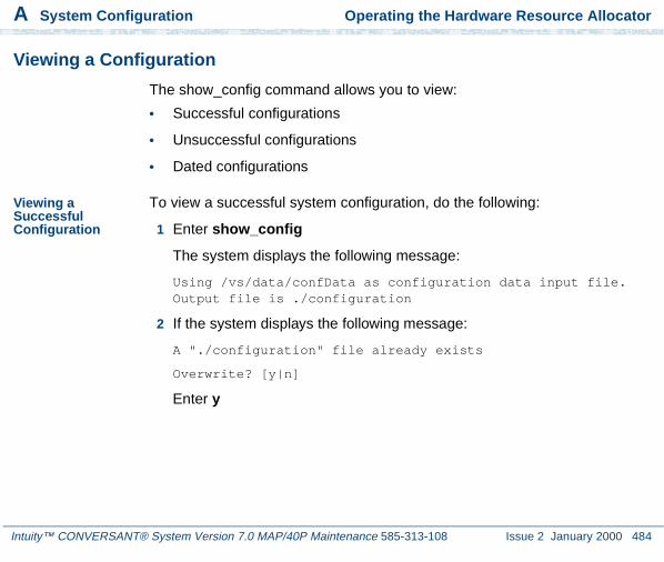
A System Configuration Operating the Hardware Resource Allocator
Intuity™ CONVERSANT® System Version 7.0 MAP/40P Maintenance 585-313-108 Issue 2 January 2000 484
Viewing a Configuration
The show_config command allows you to view:
• Successful configurations
• Unsuccessful configurations
• Dated configurations
Viewing a Successful Configuration
To view a successful system configuration, do the following:
1 Enter show_config
The system displays the following message:
Using /vs/data/confData as configuration data input file. Output file is ./configuration
2 If the system displays the following message:
A "./configuration" file already exists
Overwrite? [y|n]
Enter y

A System Configuration Operating the Hardware Resource Allocator
Intuity™ CONVERSANT® System Version 7.0 MAP/40P Maintenance 585-313-108 Issue 2 January 2000 485
3 The system displays the following message:
Configuration has been written to the "./configuration"
4 Enter vi ./configuration
The system displays the System Configuration Table screen (Figure 123 on page 486).

A System Configuration Operating the Hardware Resource Allocator
Intuity™ CONVERSANT® System Version 7.0 MAP/40P Maintenance 585-313-108 Issue 2 January 2000 486
Figure 123. Partial System Configuration Table Screen
SYSTEM CONFIGURATION TABLE
PLATFORM
MAP/40PDescription: MAP/40P platform w/ PCI backplane and P5200 CPUBackplane: PCICPU: P5200
DEVICES
Device Name: VIDEO_CONTROLLER Device Description: [S]VGA Video Card
LOCATION TDM? INTR IOADDR RAMADDR DMA PORT SCSI ID-------- ---- ---- -------- --------- --- ---------- ---------- PCI 2 3b0 a0000
Device Name: RMB_M Device Description: Remote Maintenance Board with modem interface
LOCATION TDM? INTR IOADDR RAMADDR DMA PORT SCSI ID-------- ---- ---- -------- --------- --- ---------- ----------

A System Configuration Operating the Hardware Resource Allocator
Intuity™ CONVERSANT® System Version 7.0 MAP/40P Maintenance 585-313-108 Issue 2 January 2000 487
5 Use the up arrow and down arrow keys to move through the screen.
Viewing an Unsuccessful Configuration
To view an unsuccessful system configuration, do the following:
1 Enter show_config fail
The system displays the following message:
Using /vs/data/fail_data as configuration data input file. Output file is ./failed_config
Configuration has been written to the "./failed_config"
2 Enter vi ./failed_config
The system displays a System Configuration Table screen similar to the one shown in Figure 123 on page 486. Asterisks (*) next to any field value indicate an unresolved resource conflict.
3 Use the up arrow and down arrow keys to move through the screen.
Viewing a Dated Configuration
• Show a dated configuration
You can also use show_config to view a previous configuration file saved by the configure program. To do this, type the command with a file name argument (for example, show_config /vs/data/conf_MMDDYY). This command line expands the contents of the conf_MMDDYY file (if it exists)

A System Configuration Operating the Hardware Resource Allocator
Intuity™ CONVERSANT® System Version 7.0 MAP/40P Maintenance 585-313-108 Issue 2 January 2000 488
and prints its output to the screen. The program prompts you for an output file name so as to specify the output to this file rather than to the./configuration file.
To view a dated system configuration, do the following:
1 Enter show_config /vs/data/conf_MMDDYY
Where MMDDYY is the month, day, and year of the configuration you want to view.
The system displays the following message:
Using /vs/data/conf_MMDDYY as configuration data input file.
Please specify full path name of output file for this configuration:
2 Enter pathname/fn
where pathname is the file location and fn is the filename.
The system displays the following message:
Configuration has been written to the "pathname/fn" file.
3 Enter vi pathname/fn
where pathname is the file location and fn is the filename from step 2.
The system displays a System Configuration Table screen similar to the one shown in Figure 123 on page 486.

A System Configuration Operating the Hardware Resource Allocator
Intuity™ CONVERSANT® System Version 7.0 MAP/40P Maintenance 585-313-108 Issue 2 January 2000 489
4 Use the up arrow and down arrow keys to move through the screen.
Comparing a Configuration
The hardware configuration checker verifies that the device configuration information associated with the hardware resource allocator is consistent with the actual system device configuration. To verify the configuration, do the following:
1 Enter hconchk
The system displays the following message:
hconchk: The hardware configuration check is complete.
If you receive any other error message or warning see “Alarm and Log Messages,” in the Intuity CONVERSANT System Reference, 585-313-205.
Presetting Hardware Resources
The preset option allows you to preset the resources used for a particular card. This makes the card compatible and interchangeable with any of your application setups. The purpose of this option is to give you the flexibility to use your hardware with more than one application. You may want to preset

A System Configuration Operating the Hardware Resource Allocator
Intuity™ CONVERSANT® System Version 7.0 MAP/40P Maintenance 585-313-108 Issue 2 January 2000 490
certain resources of a single new device being selected for a configuration (for example, to force the configure program to select interrupt 6 for a particular device being specified).
If you have preset hardware resources, the Intuity CONVERSANT Hardware Resource Allocator makes one attempt at configuration. If this attempt is successful, the program terminates normally. A second attempt is not performed.
Use the following procedure to preset resources:
1 When you specify a single device, the system displays the following prompt:
Do you wish to preset any hardware options of <device name>? [y|(n)]
2 Press y
The system asks you to select a value for the following parameters (where applicable):
~ IRQ
~ I/O address
~ RAM address
~ DMA address

A System Configuration Operating the Hardware Resource Allocator
Intuity™ CONVERSANT® System Version 7.0 MAP/40P Maintenance 585-313-108 Issue 2 January 2000 491
When you have entered all applicable presets, the system displays the following message:
Press Enter to continue...
3 Press ENTER.
The system displays the following message:
1 XXX device(s) added.
Press Enter to continue...
4 Press ENTER.
The system displays the Device Menu screen (Figure 122 on page 480).
5 Enter hconchk
The system displays the following message:
hconchk: The hardware configuration check is complete.

A System Configuration Configuration Device Data
Intuity™ CONVERSANT® System Version 7.0 MAP/40P Maintenance 585-313-108 Issue 2 January 2000 492
Configuration Device Data
The deviceData file stores the devices and the attributes for creating a configuration. The show_devices command displays and prints to a file all devices and their attributes as represented in the deviceData file.
! CAUTION:Do not alter this file.
The show_devices Command
The show_devices command uncompresses the database of devices and their attributes contained in the deviceData file and displays the information on the screen. At the same time, it creates a ./devices file so that you can send this information to a printer.
If a ./devices file already exists, you are prompted as to whether it is acceptable to overwrite the existing file.

Intuity™ CONVERSANT® System Version 7.0 MAP/40P Maintenance 585-313-108 Issue 2 January 2000 493
B Component Ordering Numbers
Overview
This appendix provides the ordering numbers for replacement components used in the MAP/40P.

B Component Ordering Numbers Component Ordering Numbers
Intuity™ CONVERSANT® System Version 7.0 MAP/40P Maintenance 585-313-108 Issue 2 January 2000 494
Component Ordering Numbers
Table 24 on page 494 contains a list of c omponent ordering numbers.
Table 24. Component Ordering Numbers
Basic Component Description Order Number
Adapter, 356A 104158829
Adapter, 356B 105197297
Adapter, 415A (for extending E1/T1 cables) 103942272
Adapter, electrical, DCE female 407345776
Adapter, electrical, DCE male (wyse trm, prntrs) 407050111
Adapter, RJ45--DB25, DCE male (octopus), terminals and printers
406983171
Adapter, RJ45--DB25, DCE female (octopus), terminals and printers
406938189
Adapter, RJ45--DB-25, DTE male (octopus), modem connections
406983155
Adapter, electrical, DTE female 4073457681 of 15

B Component Ordering Numbers Component Ordering Numbers
Intuity™ CONVERSANT® System Version 7.0 MAP/40P Maintenance 585-313-108 Issue 2 January 2000 495
Adapter, electrical, DTE male (modems) 407050095
Adapter, electrical, jack to jack 407005255
Adapter, electrical, external SCSI 407524073
Adapter, T1-to-551 Paradyne CSU 407665884
Backplane, 12-slot 406900084
Backplane, 13-slot (9-ISA, 3-PCI, 1-CPU) 407788702
Base, tower 406900019
Bezel, front 406900001
Bezel 407791060
Brackets, PC filter (20) 406798686
Cable assembly, 386 keyboard/reset 601436066
Cable assembly, 486 keyboard adapter 601436082
Cable assembly, 486 reset 601436090
Cable assembly, 9 position TDM bus 601412836
Table 24. Component Ordering Numbers
Basic Component Description Order Number
2 of 15

B Component Ordering Numbers Component Ordering Numbers
Intuity™ CONVERSANT® System Version 7.0 MAP/40P Maintenance 585-313-108 Issue 2 January 2000 496
Cable assembly, audio input/output 407667757
Cable assembly, COM2 406899963
Cable assembly, CPU extension 601436132
Cable assembly, disk activity 406899856
Cable assembly, E1 M/M, 25 ft (BNC Coaxial) 407615285
Cable assembly, E1 M/M, 75 ft (BNC Coaxial) 407615277
Cable assembly, E1/Aculab, 75 Ohm M/M 407276211
Cable assembly, E1/T1 MF crossover adapter (TwPr) 407617968
Cable assembly, E1/T1 M/M, 25 ft (TwPr) 407613983
Cable assembly, E1/T1 M/M, 75 ft (TwPr) 407613975
Cable assembly, EMI suppression (RMB) 407265529
Cable assembly, diskette drive 601412851
Cable assembly, diskette drive, LED 407789932
Cable assembly, diskette drive (SCSI units) 601412851
Table 24. Component Ordering Numbers
Basic Component Description Order Number
3 of 15

B Component Ordering Numbers Component Ordering Numbers
Intuity™ CONVERSANT® System Version 7.0 MAP/40P Maintenance 585-313-108 Issue 2 January 2000 497
Cable assembly, hard drive 601412844
Cable assembly, LED PCB/fan 406899872
Cable assembly, M/F RS232 405119355
Cable assembly, reset/dual keyboard 406899997
Cable assembly, reset/dual keyboard 407076876
Cable assembly, SCSI peripheral control 601436058
Cable assembly, SP/CMP bus 601412828
Cable assembly, switch power extension 406932947
Cable assembly, T1, line side adapter 601806649
Cable assembly, T1, 75 ft 601386873
Cable assembly, tape drive 601415227
Cable assembly, TDM Bus, 9 Pos. 601412836
Cable assembly, telephone cord, 3-ft 601448632
Cable assembly, utility harness 407789916
Table 24. Component Ordering Numbers
Basic Component Description Order Number
4 of 15

B Component Ordering Numbers Component Ordering Numbers
Intuity™ CONVERSANT® System Version 7.0 MAP/40P Maintenance 585-313-108 Issue 2 January 2000 498
Cable assembly, bus activity (P5, 100-PCI) 601818206
Cable assembly, bus mouse (P5 MAPs) 601855851
Cable assembly, SCSI (P5 & 525-Mbyte tape drive) 601818230
Cable assembly, SCSI (P5 and 2-Gbyte tape drive) 601818313
Cable assembly, SCSI 601854706
Cable assembly, floppy (P5) 601818339
Cable assembly, floppy 407795947
Cable assembly, keyboard (P5, 100-PCI, 100C-PCI) 601818412
Cable assembly, keyboard 407789890
Cable assembly, modular, 25-ft RJ-45 reversing (EQUINOX SSt-8I)
407463157
Card guide, 4-in. 407789049
Circuit card, 8-port asynchronous interface 406618538
Circuit card, 8-port asynchronous interface 407009046
Table 24. Component Ordering Numbers
Basic Component Description Order Number
5 of 15

B Component Ordering Numbers Component Ordering Numbers
Intuity™ CONVERSANT® System Version 7.0 MAP/40P Maintenance 585-313-108 Issue 2 January 2000 499
Circuit card, companion processor (CMP) 106024151
Circuit card, companion processor (CMP) 106944960
Circuit card, CPU, 25-MHz, 0 Mbyte memory 407019272
Circuit card, CPU, 25-MHz, 0 Mbyte memory 407300276
Circuit card, CPU, 25-MHz, 12 Mbyte memory 406900100
Circuit card, CPU, 25-MHz, 12 Mbyte memory 406989806
Circuit card, CPU, 50-MHz, 0 Mbyte memory 407019306
Circuit card, CPU, 50-MHz, 0 Mbyte memory 407300342
Circuit card, CPU, P5120, 0 Mbyte memory 407515204
Circuit card, DCP, PC/PBX interface 106986870
Circuit card, disk drive controller 406222109
Circuit card, E1, digital interface 106733348
Circuit card, Ethernet LAN adapter (10MB/PCI) 407553254
Circuit card, Ethernet LAN interface, Version 1 407199538
Table 24. Component Ordering Numbers
Basic Component Description Order Number
6 of 15

B Component Ordering Numbers Component Ordering Numbers
Intuity™ CONVERSANT® System Version 7.0 MAP/40P Maintenance 585-313-108 Issue 2 January 2000 500
Circuit card, Ethernet LAN interface, Version 2 601834153
Circuit card, fax, TR114+14L (Australia) 407334754
Circuit card, fax, TR114+14L (Australia) 407433424
Circuit card, fax, TR114+14L (Australia) 407644673
Circuit card, fax, TR114+14L (France) 407658749
Circuit card, fax, TR114+14L (Germany) 407468982
Circuit card, fax, TR114+14L (Germany) 407644681
Circuit card, fax, TR114+14L (Japan) 407389659
Circuit card, fax, TR114+14L (Japan) 407644707
Circuit card, fax, TR114+14L (Netherlands) 407455484
Circuit card, fax, TR114+14L (Netherlands) 407644715
Circuit card, fax, TR114+14L (Spain) 407658731
Circuit card, fax, TR114+14L (United Kingdom) 407334770
Circuit card, fax, TR114+14L (United Kingdom) 407433440
Table 24. Component Ordering Numbers
Basic Component Description Order Number
7 of 15
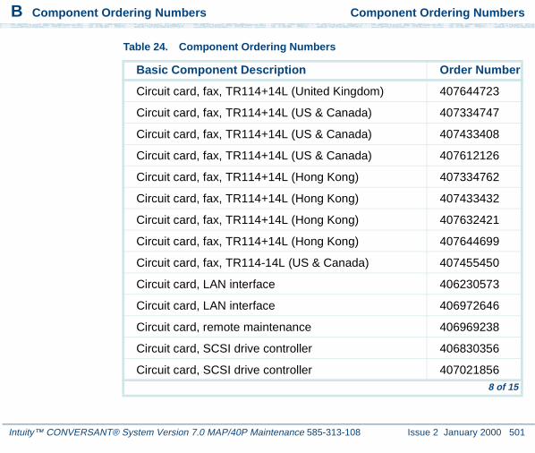
B Component Ordering Numbers Component Ordering Numbers
Intuity™ CONVERSANT® System Version 7.0 MAP/40P Maintenance 585-313-108 Issue 2 January 2000 501
Circuit card, fax, TR114+14L (United Kingdom) 407644723
Circuit card, fax, TR114+14L (US & Canada) 407334747
Circuit card, fax, TR114+14L (US & Canada) 407433408
Circuit card, fax, TR114+14L (US & Canada) 407612126
Circuit card, fax, TR114+14L (Hong Kong) 407334762
Circuit card, fax, TR114+14L (Hong Kong) 407433432
Circuit card, fax, TR114+14L (Hong Kong) 407632421
Circuit card, fax, TR114+14L (Hong Kong) 407644699
Circuit card, fax, TR114-14L (US & Canada) 407455450
Circuit card, LAN interface 406230573
Circuit card, LAN interface 406972646
Circuit card, remote maintenance 406969238
Circuit card, SCSI drive controller 406830356
Circuit card, SCSI drive controller 407021856
Table 24. Component Ordering Numbers
Basic Component Description Order Number
8 of 15

B Component Ordering Numbers Component Ordering Numbers
Intuity™ CONVERSANT® System Version 7.0 MAP/40P Maintenance 585-313-108 Issue 2 January 2000 502
Circuit card, Speech and Signal Processor (SSP) 107570491
Circuit card, Tip/Ring (IVC6) 106406580
Circuit card, Tip/Ring (IVC6-1A) 107213944
Circuit card, Tip/Ring (IVP4) analog interface 106024094
Circuit card, Tip/Ring (IVP4) analog interface 106769227
Circuit card, Tip/Ring (IVP6) analog interface 105732267
Circuit card, Tip/Ring (IVP6) analog interface 106430861
Circuit card, Tip/Ring (IVP6) analog interface 107213936
Circuit card, Tip/Ring (IVP6-IA) analog interface 107101164
Circuit card, Tip/Ring (IVP6-ID) analog interface 107213381
Circuit card, Tip/Ring (IVP6-IU) analog interface 106560170
Circuit card, Tip/Ring, Next Generation (NGTR) 107224586
Circuit card, serial synchronous interface 406715771
Circuit card, signal processor (SP) 106406572
Table 24. Component Ordering Numbers
Basic Component Description Order Number
9 of 15

B Component Ordering Numbers Component Ordering Numbers
Intuity™ CONVERSANT® System Version 7.0 MAP/40P Maintenance 585-313-108 Issue 2 January 2000 503
Circuit card, signal processor (SP) 106439839
Circuit card, starlan interface 406817999
Circuit card, synchronous host interface (FIFO/SIB) 407176601
Circuit card, synchronous interface 601824956
Circuit card, T1 digital interface 106077753
Circuit card, T1 digital interface with upgrade kit 601413172
Circuit card, tape drive controller 406272799
Circuit card, token ring, Version 1 407199637
Circuit card, token ring, Version 2 407664507
Circuit card, video controller 406901884
Circuit card, video controller 407095835
Circuit card, video controller 407356955
Circuit card, video controller, PCI 407783620408320091
Table 24. Component Ordering Numbers
Basic Component Description Order Number
10 of 15

B Component Ordering Numbers Component Ordering Numbers
Intuity™ CONVERSANT® System Version 7.0 MAP/40P Maintenance 585-313-108 Issue 2 January 2000 504
Connector, BNC Wye LAN 405990169
Cord, 10-pin modular, 10 ft 846362705
Cord, 10-pin modular, 10 ft 846983039
Cord, 6-pin modular, 14-ft 102937604
Cord, AC power, 9-ft 406900092
Cord, AC power, Australia, 8-ft 407051630
Cord, AC power, Chile (Italy-style), 6-ft 407515196
Cord, AC power, Germany, 6-ft 407051648
Cord, AC power, India, 8-ft 407406735
Cord, AC power, Japan, 8-ft 407406727
Cord, AC power, United Kingdom, 6-ft 406999243
Cord, AC power, United States, 8-ft. 407789924
Cord, power, monitor (PC style) 407115591
Cord, telephone, 25-ft 103623195
Table 24. Component Ordering Numbers
Basic Component Description Order Number
11 of 15

B Component Ordering Numbers Component Ordering Numbers
Intuity™ CONVERSANT® System Version 7.0 MAP/40P Maintenance 585-313-108 Issue 2 January 2000 505
Cord, telephone, DW8A-SE, 25 ft 103848800
Coupler, E1, F/F (BNC Coaxial) 407617901
Cover, dress 406900563
Cover, filter 407792464
Disk drive, floppy, 1.44-Mbyte 406832584
Disk drive, hard, 200-Mbyte 406902791
Disk drive, hard, 200-Mbyte 407021153
Disk drive, hard, SCSI, 1.2-Gbyte 406844134
Disk drive, hard, SCSI, 1.75-Gbyte 407071950
Disk drive, hard, SCSI, 2.0-Gbyte (Starfire) 407340942
Disk drive, hard, SCSI, 2.0-Gbyte (Medalist) 407773555
Door 407791102
Door, drive cover 406900043
Door, vented 406900035
Table 24. Component Ordering Numbers
Basic Component Description Order Number
12 of 15

B Component Ordering Numbers Component Ordering Numbers
Intuity™ CONVERSANT® System Version 7.0 MAP/40P Maintenance 585-313-108 Issue 2 January 2000 506
Fan, card cage, 85-cfm, 12VDC 406900126
Fan, card cage (Includes Connector & 2 Snap Rivets) 407789031
Feet, tower (2-feet & mounting hardware) 407789056
Filter, card cage 407791144
Filter, vented door (quantity: 5) 406900050
IC, 16-Mbyte SIMM 406997601
IC, 16-Mbyte SIMM 407244094
IC, 16-Mbyte SIMM 407420116
IC, 16-Mbyte SIMM 407608199
IC, 16-Mbyte SIMM 407701747
IC, 32-Mbyte SIMM 407420124
IC, 32-Mbyte SIMM 407700285
IC, 4-Mbyte SIMM 406666727
IC, 4-Mbyte SIMM 406995522
Table 24. Component Ordering Numbers
Basic Component Description Order Number
13 of 15

B Component Ordering Numbers Component Ordering Numbers
Intuity™ CONVERSANT® System Version 7.0 MAP/40P Maintenance 585-313-108 Issue 2 January 2000 507
IC, 4-Mbyte SIMM 407022961
IC, 4-Mbyte SIMM 407056696
Keyboard (GIS gray) 407104066
Miscellaneous hardware kit 406899849
Module, voice workstation 601459621
Monitor, color, VGA 406594952
Monitor, color, VGA (Beige housing) 407773316
Monitor, color, VGA (GIS gray) 407088335
Mount, LED 407789072
Mouse, serial 407050970
Mouse, serial 407176593
Power supply, AC, 325-Watts 406900027
Power supply, AC, 325-Watts 406962654
Power supply, AC, 350-Watts 407561661
Table 24. Component Ordering Numbers
Basic Component Description Order Number
14 of 15

B Component Ordering Numbers Component Ordering Numbers
Intuity™ CONVERSANT® System Version 7.0 MAP/40P Maintenance 585-313-108 Issue 2 January 2000 508
Resistor SIP, TDM terminator 403789167
Switch, reset 406901926
Switch, rocker 406901918
Switch, rocker, power 407793843
Tape drive, SCSI streaming 406844126
Tape drive, SCSI streaming, 2-Gbyte, black 407334507
Tape drive, streaming 406664862
Terminator, single-ended active, SCSI-2 407524719
Toroid, ring type 405853458
Toroid, split type 407616846
Table 24. Component Ordering Numbers
Basic Component Description Order Number
15 of 15

Intuity™ CONVERSANT® System Version 7.0 MAP/40P Maintenance 585-313-108 Issue 2 January 2000 509
C How to Build a System Using ThisBook
Overview
This appendix provides the sequence of operations for building an Intuity CONVERSANT system.

C How to Build a System Using This Book Checklist for Building a System
Intuity™ CONVERSANT® System Version 7.0 MAP/40P Maintenance 585-313-108 Issue 2 January 2000 510
Checklist for Building a System
The following checklist (Table 25 on page 510) assumes that you are starting with a MAP/40P shell which has only the power supply and the 12-slot backplane.
If your system does not have a power supply or a 12-slot backplane included, see Chapter 4, Replacing Other Components , for the installation procedures.
Table 25. Checklist for Building a System
Task Description Comments See ✓
1 Acquire all of the components necessary to build your system.
Appendix B, Component Ordering Numbers
2 Determine the slot and bay locations for the equipment.
Appendix A, System Configuration
3 Install the hard disk drive(s).
Chapter 3, Replacing the Hard Disk Drive
4 Install the tape drive. Chapter 4, Replacing Other Components
1 of 2

C How to Build a System Using This Book Checklist for Building a System
Intuity™ CONVERSANT® System Version 7.0 MAP/40P Maintenance 585-313-108 Issue 2 January 2000 511
5 Install the diskette drive. Chapter 4, Replacing Other Components
6 Install the circuit cards. Chapter 2, Installing or Replacing Circuit Cards
7 Apply power to the unit. Chapter 1, Getting Inside the Computer
8 Install the base system software.
Chapter 6, Installing Base System Software
9 Install the Intuity system software.
Chapter 7, Installing the Intuity CONVERSANT System Software
10 Install the UNIX multi-user software.
This is an optional feature software.
Chapter 8, Installing the Optional Feature Software
Table 25. Checklist for Building a System
Task Description Comments See ✓
2 of 2

Intuity™ CONVERSANT® System Version 7.0 MAP/40P Maintenance 585-313-108 Issue 2 January 2000 512
D Disaster Recovery Checklists
Disaster Recovery Checklists
The following checklists are included in this section:
• Checklist for Software Reloading on Nonmirrored Intuity CONVERSANT Systems with Existing Hard Disk Drives on page 513
• Checklist for Intuity CONVERSANT Systems with All New Hard Disk Drives on page 514
• Checklist for Nonmirrored Intuity CONVERSANT Systems with a New Hard Disk Drive 0 and an Existing Hard Disk Drive 1 on page 516
• Checklist for Nonmirrored Intuity CONVERSANT Systems with an Existing Hard Disk Drive 0 and a New Hard Disk Drive 1 on page 517
• Checklist for Mirrored Intuity CONVERSANT Systems with a New Hard Disk Drive 0 and an Existing Hard Disk Drive 1 on page 519
• Checklist for Mirrored Intuity CONVERSANT Systems with an Existing Hard Disk Drive 0 and a New Hard Disk Drive 1 on page 521

D Disaster Recovery Checklists Disaster Recovery Checklists
Intuity™ CONVERSANT® System Version 7.0 MAP/40P Maintenance 585-313-108 Issue 2 January 2000 513
Checklist for Software Reloading on Nonmirrored Intuity CONVERSANTSystems with Existing Hard Disk Drives
The procedures in Table 26 on page 513 should be conducted when your Intuity CONVERSANT system experiences a software disaster. This checklist should not be used if hard disk drives are being replaced.
Table 26. Checklist for Software Reloading for Nonmirrored Intuity CONVERSANT Systems with Existing Hard Disk Drives
✔ Task Reference Documentation
Locate the most recent mkimage backup tape. You will also need to use any spres backup tape which has been created.
Shutdown the Intuity CONVERSANT system.
“Shut Down the System,” in “Common System Procedures,” in the Intuity CONVERSANT System Reference, 585-313-205.
Leave all hard disks connected to the SCSI bus.
1 of 2

D Disaster Recovery Checklists Disaster Recovery Checklists
Intuity™ CONVERSANT® System Version 7.0 MAP/40P Maintenance 585-313-108 Issue 2 January 2000 514
Checklist for Intuity CONVERSANT Systems with All New Hard Disk Drives
The procedures in this checklist (Table 27 on page 515) should be conducted when you are replacing both hard disk drives on your Intuity CONVERSANT system. There are no provisions in this checklist for recovering existing file system. As a result, this checklist should not be used if either hard disk drive has been previously used in your Intuity CONVERSANT system.
Restore the system using the mkimage backup tape.
“Restore the System,” in “Common System Procedures,” in the Intuity CONVERSANT System Reference, 585-313-205
Restore any speech files using the spres backup tape.
Intuity CONVERSANT System Version 7 Speech Development, Processing, and Recognition, 585-313-201.
Table 26. Checklist for Software Reloading for Nonmirrored Intuity CONVERSANT Systems with Existing Hard Disk Drives
✔ Task Reference Documentation
2 of 2
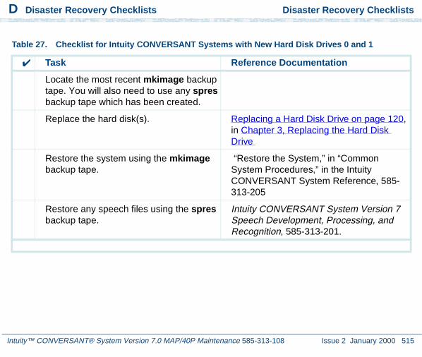
D Disaster Recovery Checklists Disaster Recovery Checklists
Intuity™ CONVERSANT® System Version 7.0 MAP/40P Maintenance 585-313-108 Issue 2 January 2000 515
Table 27. Checklist for Intuity CONVERSANT Systems with New Hard Disk Drives 0 and 1
✔ Task Reference Documentation
Locate the most recent mkimage backup tape. You will also need to use any spres backup tape which has been created.
Replace the hard disk(s). Replacing a Hard Disk Drive on page 120, in Chapter 3, Replacing the Hard Disk Drive
Restore the system using the mkimage backup tape.
“Restore the System,” in “Common System Procedures,” in the Intuity CONVERSANT System Reference, 585-313-205
Restore any speech files using the spres backup tape.
Intuity CONVERSANT System Version 7 Speech Development, Processing, and Recognition, 585-313-201.

D Disaster Recovery Checklists Disaster Recovery Checklists
Intuity™ CONVERSANT® System Version 7.0 MAP/40P Maintenance 585-313-108 Issue 2 January 2000 516
Checklist for Nonmirrored Intuity CONVERSANT Systems with a New Hard Disk Drive 0 and an Existing Hard Disk Drive 1
The procedures in this checklist (Table 28 on page 516) should be conducted on a two disk nonmirrored Intuity CONVERSANT system in which Hard Disk Drive 0 has failed. This checklist should not be used if Hard Disk Drive 1 has also failed.
Table 28. Checklist for Nonmirrored Lucent Intuity Systems with a New Hard Disk Drive 0 and an Existing Hard Disk Drive 1
✔ Task Reference Documentation
Locate the most recent mkimage backup tape. You will also need to use any spres backup tape which has been created.
Replace the hard disk drive. Replacing a Hard Disk Drive on page 120, in Chapter 3, Replacing the Hard Disk Drive
1 of 2
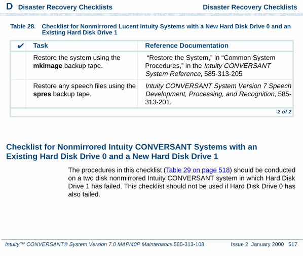
D Disaster Recovery Checklists Disaster Recovery Checklists
Intuity™ CONVERSANT® System Version 7.0 MAP/40P Maintenance 585-313-108 Issue 2 January 2000 517
Checklist for Nonmirrored Intuity CONVERSANT Systems with an Existing Hard Disk Drive 0 and a New Hard Disk Drive 1
The procedures in this checklist (Table 29 on page 518) should be conducted on a two disk nonmirrored Intuity CONVERSANT system in which Hard Disk Drive 1 has failed. This checklist should not be used if Hard Disk Drive 0 has also failed.
Restore the system using the mkimage backup tape.
“Restore the System,” in “Common System Procedures,” in the Intuity CONVERSANT System Reference, 585-313-205
Restore any speech files using the spres backup tape.
Intuity CONVERSANT System Version 7 Speech Development, Processing, and Recognition, 585-313-201.
Table 28. Checklist for Nonmirrored Lucent Intuity Systems with a New Hard Disk Drive 0 and an Existing Hard Disk Drive 1
✔ Task Reference Documentation
2 of 2
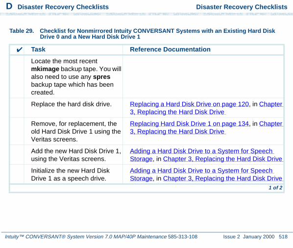
D Disaster Recovery Checklists Disaster Recovery Checklists
Intuity™ CONVERSANT® System Version 7.0 MAP/40P Maintenance 585-313-108 Issue 2 January 2000 518
Table 29. Checklist for Nonmirrored Intuity CONVERSANT Systems with an Existing Hard Disk Drive 0 and a New Hard Disk Drive 1
✔ Task Reference Documentation
Locate the most recent mkimage backup tape. You will also need to use any spres backup tape which has been created.
Replace the hard disk drive. Replacing a Hard Disk Drive on page 120, in Chapter 3, Replacing the Hard Disk Drive
Remove, for replacement, the old Hard Disk Drive 1 using the Veritas screens.
Replacing Hard Disk Drive 1 on page 134, in Chapter 3, Replacing the Hard Disk Drive
Add the new Hard Disk Drive 1, using the Veritas screens.
Adding a Hard Disk Drive to a System for Speech Storage, in Chapter 3, Replacing the Hard Disk Drive
Initialize the new Hard Disk Drive 1 as a speech drive.
Adding a Hard Disk Drive to a System for Speech Storage, in Chapter 3, Replacing the Hard Disk Drive
1 of 2

D Disaster Recovery Checklists Disaster Recovery Checklists
Intuity™ CONVERSANT® System Version 7.0 MAP/40P Maintenance 585-313-108 Issue 2 January 2000 519
Checklist for Mirrored Intuity CONVERSANT Systems with a New Hard Disk Drive 0 and an Existing Hard Disk Drive 1
The procedures in this checklist (Table 31 on page 522) should be conducted on a two disk mirrored Intuity CONVERSANT system in which Hard Disk Drive 0 has failed. This checklist should not be used if Hard Disk Drive 1 has also failed.
Exit the Veritas screens. Replacing Hard Disk Drive 1, in Chapter 3, Replacing the Hard Disk Drive
Restore any speech files using the spres backup tape.
Intuity CONVERSANT System Version 7 Speech Development, Processing, and Recognition, 585-313-201.
Table 29. Checklist for Nonmirrored Intuity CONVERSANT Systems with an Existing Hard Disk Drive 0 and a New Hard Disk Drive 1
✔ Task Reference Documentation
2 of 2

D Disaster Recovery Checklists Disaster Recovery Checklists
Intuity™ CONVERSANT® System Version 7.0 MAP/40P Maintenance 585-313-108 Issue 2 January 2000 520
Table 30. Checklist for Mirrored Intuity CONVERSANT Systems with a New Hard Disk Drive 0 and an Existing Hard Disk Drive 1
✔ Task Reference Documentation
Locate the diskette labelled "VERITAS Boot Floppy 1 of 1".
Replace the hard disk drive. Replacing a Hard Disk Drive, in Chapter 3, Replacing the Hard Disk Drive
Reboot the system with the diskette labelled "VERITAS Boot Floppy 1 of 1" in the diskette drive.
Replacing Hard Disk Drive 0 (Mirrored System), in Chapter 3, Replacing the Hard Disk Drive
Remove, for replacement, the old Hard Disk Drive 0 using the Veritas screens.
Replacing Hard Disk Drive 0 (Mirrored System), in Chapter 3, Replacing the Hard Disk Drive
Replace the old Hard Disk Drive 0 with the new Hard Disk Drive 0, using the Veritas screens.
Replacing Hard Disk Drive 0 (Mirrored System), in Chapter 3, Replacing the Hard Disk Drive
Create a partition on Hard Disk Drive 0 using the Veritas screens.
Replacing Hard Disk Drive 0 (Mirrored System), in Chapter 3, Replacing the Hard Disk Drive
1 of 2

D Disaster Recovery Checklists Disaster Recovery Checklists
Intuity™ CONVERSANT® System Version 7.0 MAP/40P Maintenance 585-313-108 Issue 2 January 2000 521
Checklist for Mirrored Intuity CONVERSANT Systems with an Existing Hard Disk Drive 0 and a New Hard Disk Drive 1
The procedures in this checklist (Table 31 on page 522) should be conducted on a two disk mirrored Intuity CONVERSANT system in which Hard Disk Drive 1 has failed. This checklist should not be used if Hard Disk Drive 0 has also failed.
Exit the Veritas screens. Replacing Hard Disk Drive 0 (Mirrored System), in Chapter 3, Replacing the Hard Disk Drive
Remove the diskette labelled "VERITAS Boot Floppy 1 of 1" from the diskette drive.
Table 30. Checklist for Mirrored Intuity CONVERSANT Systems with a New Hard Disk Drive 0 and an Existing Hard Disk Drive 1
✔ Task Reference Documentation
2 of 2
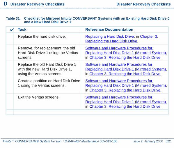
D Disaster Recovery Checklists Disaster Recovery Checklists
Intuity™ CONVERSANT® System Version 7.0 MAP/40P Maintenance 585-313-108 Issue 2 January 2000 522
Table 31. Checklist for Mirrored Intuity CONVERSANT Systems with an Existing Hard Disk Drive 0 and a New Hard Disk Drive 1
✔ Task Reference Documentation
Replace the hard disk drive. Replacing a Hard Disk Drive, in Chapter 3, Replacing the Hard Disk Drive
Remove, for replacement, the old Hard Disk Drive 1 using the Veritas screens.
Software and Hardware Procedures for Replacing Hard Disk Drive 1 (Mirrored System), in Chapter 3, Replacing the Hard Disk Drive
Replace the old Hard Disk Drive 1 with the new Hard Disk Drive 1, using the Veritas screens.
Software and Hardware Procedures for Replacing Hard Disk Drive 1 (Mirrored System), in Chapter 3, Replacing the Hard Disk Drive
Create a partition on Hard Disk Drive 1 using the Veritas screens.
Software and Hardware Procedures for Replacing Hard Disk Drive 1 (Mirrored System), in Chapter 3, Replacing the Hard Disk Drive
Exit the Veritas screens. Software and Hardware Procedures for Replacing Hard Disk Drive 1 (Mirrored System), in Chapter 3, Replacing the Hard Disk Drive

Intuity™ CONVERSANT® System Version 7.0 MAP/40P Maintenance 585-313-108 Issue 2 January 2000 523
Glossary
Numerics
23B+D
23 bearer (communication) and 1 data (signaling) channel on a T1 PRI circuit card.
30B+D
30 bearer (communication) and 1 data (signaling) channel (plus framing channel 0) on an E1 PRI circuit card.
3270 interface
A link between one or more Intuity CONVERSANT machines and a host mainframe. In Intuity CONVERSANT system documentation, the 3270 interface specifically means the link between one or more system machines and an IBM host mainframe.
47B+D
47 bearer (communication) and 1 data (signaling) channel on two T1 PRI circuit cards.

Glossary 4ESS®
Intuity™ CONVERSANT® System Version 7.0 MAP/40P Maintenance 585-313-108 Issue 2 January 2000 524
4ESS®
A large Lucent central office switch used to route calls through the telephone network.
A AC
alternating current
ACD
automatic call distributor
AD
application dispatch
AD-API
application dispatch application programming interface
adaptive differential pulse code modulation
A means of encoding analog voice signals into digital signals by adaptively predicting future encoded voice signals. This adaptive modulation method reduces the number of bits required to encode voice. See also “pulse code modulation.”

Glossary adjunct products
Intuity™ CONVERSANT® System Version 7.0 MAP/40P Maintenance 585-313-108 Issue 2 January 2000 525
adjunct products
Products (for example, the Adjunct/Switch Application Interface) that the Intuity system administers via cut-through access to the inherent management capabilities of the product itself; this is in opposition to the ability of the Intuity CONVERSANT system to administer the switch directly.
Adjunct/Switch Application Interface
An optional feature package that provides an Integrated Services Digital Network-based interface between Lucent Technologies PBXs and adjunct processors.
ADPCM
adaptive differential pulse code modulation
ADU
asynchronous data unit
advanced speech recognition
A speech recognition ability that allows the system to understand WholeWord and FlexWord™ inputs from callers.
affiliate
A business organization that Lucent controls or with which Lucent is in partnership.

Glossary AGL
Intuity™ CONVERSANT® System Version 7.0 MAP/40P Maintenance 585-313-108 Issue 2 January 2000 526
AGL
application generation language
alarm relay unit
A unit used in central office telecommunication arrangements that transmits warning indicators from telephone communications equipment (such as an Intuity CONVERSANT system) to audio.
ALERT
System alerter process
alerter
A system process that responds to patterns of events logged by the “logdaemon” process.
American Standard Code for Information Interchange
A standard code for data representation that represents alphanumeric characters as binary numbers. The code includes 128 upper- and lowercase letters, numerals, and special characters. Each alphanumeric and special character has an ASCII code (binary) equivalent that is 1 byte long.

Glossary analog
Intuity™ CONVERSANT® System Version 7.0 MAP/40P Maintenance 585-313-108 Issue 2 January 2000 527
analog
An analog signal, such as voice or music, that varies in a continuous manner. An analog signal may be contrasted with a digital signal, which represents only discrete states.
ANI
automatic number identification
announcement
A message the system plays to the caller to provide information. The caller is not asked to give a response. Compare to “prompt.”
API
Application programming interface
application
The automated transaction (interactions) among the caller, the voice response system, and any databases or host computers required for your business. See also “application script.”
Glossary application administration
Intuity™ CONVERSANT® System Version 7.0 MAP/40P Maintenance 585-313-108 Issue 2 January 2000 528
application administration
The component of the Intuity CONVERSANT system that provides access to the applications currently available on your system and helps you to manage and administer them.
application installation
A two-step process in which the Intuity CONVERSANT system invokes the TSM script assembler for the specific application name and moves files to the appropriate directories.
application script
The computer program that controls the application (the transaction between the caller and the system). The Intuity CONVERSANT system provides several methods for creating application scripts, including Voice@Work, Script Builder, Transaction Assembler Script (TAS) language, and the Intuity Response Application Programming Interface (IRAPI).
application verification
A process in which the Intuity CONVERSANT system verifies that all the components needed by an application are complete.
ASCII
American Standard Code for Information Interchange

Glossary ASI
Intuity™ CONVERSANT® System Version 7.0 MAP/40P Maintenance 585-313-108 Issue 2 January 2000 529
ASI
analog switch integration
ASR
advanced speech recognition
asynchronous communication
A method of data transmission in which bits or characters are sent at irregular intervals and spaced by start and stop bits rather than by time. Compare to “synchronous communication.”
asynchronous data unit
An electronic communications device that allows computer systems to communicate over asynchronous lines more than 50 feet (15 m) in length.
automatic call distributor
That part of a telephone system that recognizes and answers incoming calls and completes these calls based on a set of instructions contained in a database. The ACD can send the call to an operator or group of operators as soon as the operator has completed a previous call or after the system has played a message to the caller.

Glossary automatic number identification
Intuity™ CONVERSANT® System Version 7.0 MAP/40P Maintenance 585-313-108 Issue 2 January 2000 530
automatic number identification
A method of identifying the calling party by automatically receiving a string of digits that identifies the calling station of a particular customer.
AYC5B
The IVP6 Tip/Ring (analog) circuit card.
AYC10
The IVC6 Tip/Ring (analog) circuit card.
AYC21
The E1/T1 (digital) circuit card.
AYC30
The NGTR (analog) circuit card.
AYC43
The speech and signal processor (SSP) circuit card.

Glossary back up
Intuity™ CONVERSANT® System Version 7.0 MAP/40P Maintenance 585-313-108 Issue 2 January 2000 531
B back up
The preservation of the information in a file in a different location, so that the data is not lost in the event of hardware or system failure.
backing up an application
Using a utility that makes an archive copy of a completed application or an interim copy of an application in progress. The back-up copy can be restored to the system if the on-line version is damaged, or if you make revisions and want to go back to the previous version.
barge-in
A capability provided by WholeWord speech recognition and Dial Pulse Recognition (DPR) that allows callers to speak or enter their responses during the prompt and have those responses recognized (similar to the Speak with Interrupt capability). See also “echo cancellation.”
batch file
A file containing one or more lines, each of which is a command executable by the UNIX shell.
BB
bulletin board

Glossary binary synchronous communications
Intuity™ CONVERSANT® System Version 7.0 MAP/40P Maintenance 585-313-108 Issue 2 January 2000 532
binary synchronous communications
A character-oriented synchronous link protocol.
blind transfer protocol
A protocol in which a call is completed as soon as the extension is dialed, without having to wait to see if the telephone is busy or if the caller answered.
bps
bits per second
BRDG
call bridging process
bridging
The process of connecting one telephone network connection to another over the Intuity CONVERSANT system TDM bus. Bridging decreases the processing load on the system since an active bridge does not require speech processing, database access, host activity, etc., for the transaction.
BSC
binary synchronous communications

Glossary bundle
Intuity™ CONVERSANT® System Version 7.0 MAP/40P Maintenance 585-313-108 Issue 2 January 2000 533
bundle
In the context of the Enhanced File Transfer package, this term is used to denote a single file, a group of files (package), or a combination of both.
byte
A unit of storage in the computer. On many systems, a byte is 8 bits (binary digits), which is the equivalent of one character of text.
C call classification analysis
A process that enables application designers to use information available within the system to classify the disposition of originated and transferred calls. Intelligent CCA is provided with the system. Full CCA is an optional feature package.
call data event
A parameter that specifies a list of variables that are appended to a call data record at the end of each call.
call data handler process
A software process that accumulates generic call statistics and application events.
Glossary called party number
Intuity™ CONVERSANT® System Version 7.0 MAP/40P Maintenance 585-313-108 Issue 2 January 2000 534
called party number
The number dialed by the person making a telephone call. Telephone switching equipment can use this number to selectively route an incoming call to a particular department or agent.
caller
The party who calls for a service, gets connected to the Intuity CONVERSANT system, and interacts with it. As the Intuity CONVERSANT system can also make outbound calls for service, the caller can also be the person who responds to those outbound calls.
call flow
See ”transaction.”
call progress tones
Standard telephony sounds that indicate the status of the call. These sounds include busy, fast busy, ringback, reorder, etc.
card cage
An area within a Intuity CONVERSANT system platform that contains and secures all of the standard and optional circuit cards used in the system.

Glossary cartridge tape drive
Intuity™ CONVERSANT® System Version 7.0 MAP/40P Maintenance 585-313-108 Issue 2 January 2000 535
cartridge tape drive
A high-capacity data storage/retrieval device that can be used to transfer large amounts of information onto high-density magnetic cartridge tape based on a predetermined format. This tape can be removed from the system and stored as a backup, or used on another system.
CAS
channel associated signalling
caution
An admonishment or advisory statement used in Intuity CONVERSANT system documentation to alert the user to the possibility of a service interruption or a loss of data.
CCA
call classification analysis
CDH
call data handler process
CELP
code excited linear prediction

Glossary central office
Intuity™ CONVERSANT® System Version 7.0 MAP/40P Maintenance 585-313-108 Issue 2 January 2000 536
central office
An office or location in which large telecommunication devices such as telephone switches and network access facilities are maintained. These locations follow strict installation and operation requirements.
central processing unit
See “processor.”
CGEN
Voice system general message class
channel
See “port.”
channel associated signaling
A type of signaling that can be used on E1 circuit cards. It occurs on channel 16.
CICS
Customer Information Control System

Glossary circuit card upgrade
Intuity™ CONVERSANT® System Version 7.0 MAP/40P Maintenance 585-313-108 Issue 2 January 2000 537
circuit card upgrade
A new circuit card that replaces an existing card in the platform. Usually the replacement is an updated version of the original circuit card to replace technology made obsolete by industry trends or a new system release.
cluster controller
A bisynchronous interface that provides a means of handling remote communication processing.
CMS
Call Management System
CO
central office
code excited linear prediction
A means of encoding analog voice signals into digital signals that provides excellent quality with use of minimum disk space.

Glossary command
Intuity™ CONVERSANT® System Version 7.0 MAP/40P Maintenance 585-313-108 Issue 2 January 2000 538
command
An instruction or request the user issues to the system software to make the system perform a particular function. An entire command consists of the command name and options.
configuration
The arrangement of the software and hardware of a computer system or network. The Intuity CONVERSANT system configuration includes either a standard or custom processor, peripheral equipment (for example, printers and modems), and software applications. Configuration also refers to the way the switch network is set up; that is, the types of products that are in the network and how those products communicate.
configuration management
The component of the system that allows you to manage the current configuration of voice channels, host sessions, and database connections, assign scripts to run on specific voice channels or host sessions, assign functionality to SSP and E1/T1 circuit cards, and perform various maintenance functions.
connect and disconnect (C and D) tones
DTMF tones that inform the system when the attendant has been connected (C) and when the caller has been disconnected (D).

Glossary connected digits
Intuity™ CONVERSANT® System Version 7.0 MAP/40P Maintenance 585-313-108 Issue 2 January 2000 539
connected digits
A sequence of digits that the system can process as a group, rather than requiring the caller to enter the digits one at a time.
Converse Data Return (conv_data)
A Script Builder action that supports the DEFINITY® call vectoring (routing) feature by enabling the switch to retain control of vector processing in the system environment. It supports the DEFINITY “converse” vector command to establish a two-way routing mechanism between the switch and the system to facilitate data passing and return.
controller circuit card
A circuit card used on a computer system that controls its basic functionality and makes the system operational. These circuit cards are used to control magnetic peripherals, video monitors, and basic system communications.
copying an application
A utility in which information from a source application is directed into the destination application.

Glossary coresidency
Intuity™ CONVERSANT® System Version 7.0 MAP/40P Maintenance 585-313-108 Issue 2 January 2000 540
coresidency
The ability of two products or services to operate and interact with each other on a single hardware platform. An example of this is the use of an Intuity CONVERSANT system along with a package from a different vendor on the same system platform.
CPE
customer provided equipment or customer premise equipment
CPN
called party number
CPT
call progress tones
CPU
central processing unit
crash
An interactive utility for examining the operating system core and for determining if system parameters are being exceeded.

Glossary CSU
Intuity™ CONVERSANT® System Version 7.0 MAP/40P Maintenance 585-313-108 Issue 2 January 2000 541
CSU
channel service unit
custom speech
Unique words or phrases to be used in Intuity CONVERSANT system voice prompts that Lucent Technologies custom records on a per-customer basis.
custom vocabulary
A specialized package of unique words or phrases created on a per-customer basis and used by WholeWord or FlexWord speech recognition.
Customer Information Control System
Part of the operating system that manages resources for running applications (for example, IND$FILE). Note that TSO and CMS provide analogous functionality in other host environments.
CVS
converse vector step

Glossary danger
Intuity™ CONVERSANT® System Version 7.0 MAP/40P Maintenance 585-313-108 Issue 2 January 2000 542
D danger
An admonishment or advisory statement used in Intuity CONVERSANT system documentation to alert the user to the possibility of personal injury or death.
data interface process
A software process that communicates with Script Builder applications.
database
A structured set of files, records, or tables.
database field
A field used to extract values from a local database and form the structure upon which a database is built.
database record
The information in a database for a person, product, event, etc. The database record is made up of individual fields for each information item.

Glossary database table
Intuity™ CONVERSANT® System Version 7.0 MAP/40P Maintenance 585-313-108 Issue 2 January 2000 543
database table
A structure, made up of columns and rows, that holds information in a database. Database tables provide a means of storing information that changes too often to “hard-code,” or store permanently, in the transaction outline.
dB
decibel
DB
database
DBC
database checking process
DBMS
database management system
DC
direct current
DCE
data communications equipment

Glossary DCP
Intuity™ CONVERSANT® System Version 7.0 MAP/40P Maintenance 585-313-108 Issue 2 January 2000 544
DCP
digital communications protocol
debug
The process of locating and correcting errors in computer programs; also referred to as “troubleshooting.”
default
The way a computer performs a task in the absence of other instructions.
default owner
The owner of a channel when no process takes ownership of that channel. The default owner holds all idle, in-service channels. In terms of the IRAPI, this is typically the Application Dispatch process.
diagnose
The process of performing diagnostics on a bus or on Tip/Ring, E1/T1, or SSP circuit cards.
dial ahead
The ability to collect and process touch-tone inputs in sequence, even when they are received before the prompts.

Glossary dial pulse recognition
Intuity™ CONVERSANT® System Version 7.0 MAP/40P Maintenance 585-313-108 Issue 2 January 2000 545
dial pulse recognition
A method of recognizing caller pulse inputs from a rotary telephone.
dialed number identification service
A service that allows incoming calls to contain information about the telephone number for which it is destined.
dial through
A capability provided by touch-tone and dial pulse recognition that allows callers to enter their responses during the prompt and have those responses recognized (similar to the Speak with Interrupt capability). See also “barge-in” and “echo cancellation”.
dictionary
A reference book containing an alphabetical list of words, with information given for each word including meaning, pronunciation, and etymology.
DIMM
dual in-line memory module
DIO
disk input and output process

Glossary DIP
Intuity™ CONVERSANT® System Version 7.0 MAP/40P Maintenance 585-313-108 Issue 2 January 2000 546
DIP
data interface process
directory
A type of file used to group and organize other files or directories.
display errdata
A command that displays system errors sent to the logger.
DMA
direct memory address
DNIS
dialed number identification service
DPR
dial pulse recognition
DSP
digital signal processor

Glossary DTE
Intuity™ CONVERSANT® System Version 7.0 MAP/40P Maintenance 585-313-108 Issue 2 January 2000 547
DTE
data terminal equipment
DTMF
dual tone multi-frequency
DTR
data terminal ready
dual 3270 links
A feature that provides an additional physical unit (PU) for a cost-effective means of connecting to two host computers. The customer can connect a system to two separate FEPs or to a single FEP shared by one or more host computers. Each link supports a maximum of 32 LUs.
dual tone multi-frequency
A touch-tone sound that is an audio signal including two different frequencies. DTMF feedback is the process of the “switch” providing this information to the system. DTMF muting is the process of ignoring these tones (which might be simulated by human speech) when they are not needed for the application.

Glossary dump space
Intuity™ CONVERSANT® System Version 7.0 MAP/40P Maintenance 585-313-108 Issue 2 January 2000 548
dump space
An area of the disk that is fixed in size and should equal the amount of RAM on the system. The operating system “dumps” an image of core memory when the system crashes. The dump can be fetched after rebooting to help in analyzing the cause of the crash.
E E&M
Ear and Mouth
E1 / T1
Digital telephony interfaces, commonly called trunks. E1 is an international standard at 2.048 Mbps. T1 is a North American standard at 1.544 Mbps.
Ear and Mouth
A common T1 trunking protocol for connection between two “switches.”
EBCDIC
Extended Binary Coded Decimal Interexchange Code

Glossary echo cancellation
Intuity™ CONVERSANT® System Version 7.0 MAP/40P Maintenance 585-313-108 Issue 2 January 2000 549
echo cancellation
The process of making the channel quiet enough so that the system can hear and recognize WholeWord and dial pulse inputs during the prompt. See also “barge-in.”
ECS
Enterprise Communications Server
editor system
A system that allows speech phrases to be displayed and edited by a user. See “Graphical Speech Editor.”
EFT
Enhanced File Transfer
EIA
Electronic Industries Association
EISA
Extended Industry Standard Architecture
EMI
electromagnetic interference

Glossary enhanced basic speech
Intuity™ CONVERSANT® System Version 7.0 MAP/40P Maintenance 585-313-108 Issue 2 January 2000 550
enhanced basic speech
Pre-recorded speech available from Lucent Technologies in several languages. Sometimes called “standard speech.”
Enhanced File Transfer
A feature that allows the transferring of files automatically between the Intuity CONVERSANT system and a synchronous host processor on a designated logical unit.
Enhanced Serial Data Interface
A software- and hardware-controlled method used to store data on magnetic peripherals.
Enterprise Communications Server
The telephony equipment that connects your business to the telephone network. Sometimes called a “switch.”
error message
A message on the screen indicating that something is wrong with a possible suggestion of how to correct it.

Glossary ESD
Intuity™ CONVERSANT® System Version 7.0 MAP/40P Maintenance 585-313-108 Issue 2 January 2000 551
ESD
electrostatic discharge
ESDI
Enhanced Serial Data Interface
ESS
electronic switching system
EST
Enhanced Software Technologies, Inc.
ET
error tracker
Ethernet
A name for a local area network that uses 10BASE5 or 10BASE2 coaxial cable and InterLAN signaling techniques.
event
The notification given to an application when some condition occurs that is generally not encountered in normal operation.

Glossary EXTA
Intuity™ CONVERSANT® System Version 7.0 MAP/40P Maintenance 585-313-108 Issue 2 January 2000 552
EXTA
external alarms feature message class
external actions
Specific predefined system tasks that Script Builder can call or invoke to interact with other products or services. When an external action is invoked, the systems displays a form that provides choices in each field for the application developer to select. Examples are Call_Bridge, Make_Call, SP_Allocate, SR_Prompt, etc. In Voice@Work, external actions are treated as “external functions.”
external functions
Specific predefined (or customer-created) system tasks that Voice@Work or Script Builder can call or invoke to interact with other products or services. The function allows the application developer to enter the argument(s) for the function to act on. Examples are concat, getarg, length, substring, etc. See also “external actions.”
F FAX Actions
An optional feature package that allows the system to send fax messages.

Glossary FCC
Intuity™ CONVERSANT® System Version 7.0 MAP/40P Maintenance 585-313-108 Issue 2 January 2000 553
FCC
Federal Communications Commission
FDD
floppy disk drive
feature
A function or capability of a product or an application within the Intuity CONVERSANT system.
feature package
An optional package that may contain both hardware and software resources to provide additional functionality to a standard system.
feature_tst script package
A standard Intuity CONVERSANT system software program that allows a user to perform self-tests of critical hardware and software functionality.
FEP
front end processor

Glossary FFE
Intuity™ CONVERSANT® System Version 7.0 MAP/40P Maintenance 585-313-108 Issue 2 January 2000 554
FFE
Form Filler Plus feature message class
field
See “database field.”
FIFO
first-in-first-out processing order
file
A collection of data treated as a basic unit of storage.
file transfer
An option that allows you to transfer files interactively or directly to and from UNIX using the file transfer system (FTS).
filename
Alphabetic characters used to identify a particular file.
FlexWord™ speech recognition
A type of speech recognition based on subword technology that recognizes phonemes or parts of words in a specific language. See also “subword technology.”
Glossary foos
Intuity™ CONVERSANT® System Version 7.0 MAP/40P Maintenance 585-313-108 Issue 2 January 2000 555
foos
facility out-of-service state
Form Filler Plus
An optional feature package that provides the capability for application scripts to record a caller’s responses to prompts for later transcription and review.
FTS
file transfer process message class
Full CCA
A feature package that augments the types of call dispositions that Intelligent CCA can provide.
function key
A key, labeled F1 through F8, on your keyboard to which the Intuity CONVERSANT system software gives special properties for manipulating the user interface.
G GEN
PRISM logger and alerter general message class

Glossary grammar
Intuity™ CONVERSANT® System Version 7.0 MAP/40P Maintenance 585-313-108 Issue 2 January 2000 556
grammar
The inputs that a recognizer can match (identify) from a caller.
Graphical Speech Editor
A window-driven, X Windows/Motif based, graphical user interface (GUI) that can be accessed to perform different functions associated with the creation and editing of speech files for applications. The editing is done on the Intuity CONVERSANT system.
GSE
Graphical Speech Editor
GUI
graphical user interface
H hard disk drive
A high-capacity data storage/retrieval device that is located inside a computer platform. A hard disk drive stores data on nonremovable high-density magnetic media based on a predetermined format for retrieval by the system at a later date.

Glossary hardware
Intuity™ CONVERSANT® System Version 7.0 MAP/40P Maintenance 585-313-108 Issue 2 January 2000 557
hardware
The physical components of a computer system. The central processing unit, disks, tape, and floppy drives, etc., are all hardware.
Hardware Resource Allocator
A software program that resolves or blocks the allocation of CPU and memory resources for controlling and optional circuit cards.
hardware upgrade
Replacement of one or more fundamental platform hardware components (for example, the CPU or hard disk drive), while the existing platform and other existing optional circuit cards remain.
HDD
hard disk drive
High Level Language Applications Programming Interface
An application programming interface that allows a user to write custom applications that can communicate with a host computer via an API.
HLLAPI
High Level Language Applications Programming Interface

Glossary HOST
Intuity™ CONVERSANT® System Version 7.0 MAP/40P Maintenance 585-313-108 Issue 2 January 2000 558
HOST
host interface process message class
host computer
A computer linked to a network to provide a range of services, such as database access and computation. The host computer operates in a time-sharing manner with other computers linked to it via the network.
hwoos
hardware out-of-service state
Hz
Hertz
I IBM
International Business Machines
iCk or ICK
The system integrity checking process.

Glossary ID
Intuity™ CONVERSANT® System Version 7.0 MAP/40P Maintenance 585-313-108 Issue 2 January 2000 559
ID
identification
IDE
integrated disk electronics
idle channel
A channel that either has no owner or is owned by its default owner and is onhook.
IE
information element
IND$FILE
The standard SNA file transfer utility that runs as an application under CICS, TSO, and CMS. IND$FILE is independent of link-level protocols such as BISYNC and SDLC.
independent software vendor
A company that has an agreement with Lucent Technologies to develop software to work with the Intuity CONVERSANT system to provide additional features required by customers.

Glossary indexed table
Intuity™ CONVERSANT® System Version 7.0 MAP/40P Maintenance 585-313-108 Issue 2 January 2000 560
indexed table
A table that, unlike a nonindexed table, can be searched via a field name that has been indexed.
industry standard architecture
A PC bus standard that allows processors and other circuit cards to communicate with each other.
INIT
voice system initialization message class
initialize
To start up the system for the first time.
inserv
in-service state
Integrated Services Digital Network
A network that provides end-to-end digital connectivity to support a wide range of voice and data services.

Glossary Integrated Voice Processing (IVP) circuit card
Intuity™ CONVERSANT® System Version 7.0 MAP/40P Maintenance 585-313-108 Issue 2 January 2000 561
Integrated Voice Processing (IVP) circuit card
The IVP6 circuit card that provides Tip/Ring connections. The NGTR (AYC30) card also provides the same functions.
intelligent CCA
Monitoring the line after dialing is complete to determine whether a busy, reorder (fast busy), or other failure has been encountered. It also recognizes when the extension is answered or if the extension is not answered after a specified number of rings. The monitoring capabilities are dependent on the network interface circuit card and protocol used
interface
The access point of a system. With respect to the Intuity CONVERSANT system, the interface is designed to provide you with easy access to the software capabilities.
interrupt
The termination of voice and/or telephony functions when some condition occurs.
Intuity Response Application Programming Interface
A library of commands that provide a standard development interface for voice-telephony applications.

Glossary IPC
Intuity™ CONVERSANT® System Version 7.0 MAP/40P Maintenance 585-313-108 Issue 2 January 2000 562
IPC
interprocess communication
IPC
intelligent ports card (IPC-900)
IPCI
integrated personal computer interface
IRAPI
Intuity Response Application Programming Interface
IRQ
interrupt request
ISA
industry standard architecture
ISDN
Integrated Services Digital Network

Glossary ISV
Intuity™ CONVERSANT® System Version 7.0 MAP/40P Maintenance 585-313-108 Issue 2 January 2000 563
ISV
independent software vendor
ITAC
International Technical Assistance Center
IVC6 circuit card (AYC10)
A Tip/Ring (analog) circuit card with six channels.
IVP6 circuit card (AYC5B)
A Tip/Ring (analog) card with six channels.
K Kbps
kilobytes per second
Kbyte
kilobyte

Glossary keyboard mapping
Intuity™ CONVERSANT® System Version 7.0 MAP/40P Maintenance 585-313-108 Issue 2 January 2000 564
keyboard mapping
In emulation mode, this feature enables the keyboard to send 3270 keyboard codes to the host according to a configuration table set up during installation.
keyword spotting
A capability provided by WholeWord speech recognition that allows the system to recognize a single word in the middle of an entire phrase spoken by a caller in response to a prompt.
L LAN
local area network
LDB
local database
LED
light-emitting diode
library states
The state information about channel activities maintained by the IRAPI.
Glossary LIFO
Intuity™ CONVERSANT® System Version 7.0 MAP/40P Maintenance 585-313-108 Issue 2 January 2000 565
LIFO
last-in-first-out processing order
line side E1
A digital method of interfacing an Intuity CONVERSANT system to a PBX or “switch” using E1-related hardware and software.
line side T1
A digital method of interfacing an Intuity CONVERSANT system to a PBX or “switch” using T1-related hardware and software.
listfile
An ASCII catalog that lists the contents of one or more talkfiles. Each application script is typically associated with a separate listfile. The listfile maps speech phrase strings used by application scripts into speech phrase numbers.
local area network
A data communications network in a limited geographical area. The LAN provides communications between computers and peripherals.
local database
A database residing on the Intuity CONVERSANT system.
Glossary LOG
Intuity™ CONVERSANT® System Version 7.0 MAP/40P Maintenance 585-313-108 Issue 2 January 2000 566
LOG
Intuity CONVERSANT system logger process message class
logical unit
A type of SNA Network Addressable Unit.
logdaemon
A UNIX system information and error logging process.
logger
See “logdaemon.”
logging on/off
Entering or exiting the Intuity CONVERSANT system software.
LSE1
line side E1
LST1
line side T1

Glossary LU
Intuity™ CONVERSANT® System Version 7.0 MAP/40P Maintenance 585-313-108 Issue 2 January 2000 567
LU
logical unit
M magnetic peripherals
Data storage devices that use magnetic media to store information. Such devices include hard disk drives, floppy disk drives, and cartridge tape drives.
main screen
The Intuity CONVERSANT system screen from which you are able to enter either the System Administration or Voice System Administration menu.
maintenance process
A software process that runs temporary diagnostics and maintains the state of circuit cards and channels.
manoos
manually out-of-service state
MAP/100P
multi application platform 100P

Glossary MAP/100C
Intuity™ CONVERSANT® System Version 7.0 MAP/40P Maintenance 585-313-108 Issue 2 January 2000 568
MAP/100C
multi application platform 100C
MAP/40P
multi application platform 40P
MAP/5P
multi application platform 5P
masked event
An event that an application can ignore (that is, the application can request not to be informed of the event).
master
A circuit card that provides clock information to the TDM bus.
Mbps
megabits per second
MByte
megabyte

Glossary megabyte
Intuity™ CONVERSANT® System Version 7.0 MAP/40P Maintenance 585-313-108 Issue 2 January 2000 569
megabyte
A unit of memory equal to 1,048,576 bytes (1024 x 1024). It is often rounded to one million.
menu
Options presented to a user on a computer screen or with voice prompts.
MF
multifrequency
MHz
megahertz
Microsoft
A manufacturer of software products, primarily for IBM-compatible computers.
mirroring
A method of data backup that allows all of the data transactions to the primary hard disk drive to be copied and maintained on a second identical drive in near real time. If the primary disk drive crashes or becomes disabled, all of the data stored on it (up to 1.2 billion bytes of information) is accessible on the second mirrored disk drive.

Glossary ms
Intuity™ CONVERSANT® System Version 7.0 MAP/40P Maintenance 585-313-108 Issue 2 January 2000 570
ms
millisecond
msec
millisecond
MS-DOS
A personal computer disk operating system developed by the Microsoft Corporation.
MTC
maintenance process
multifrequency
Dual tone digit signalling (similar to DTMF), used for trunk addressing between network switches or by network operators.
multithreaded application
A single process/application that controls several channels. Each thread of the application is managed explicitly. Typically this means state information for each thread is maintained and the state of the application on each channel is tracked.

Glossary NCP
Intuity™ CONVERSANT® System Version 7.0 MAP/40P Maintenance 585-313-108 Issue 2 January 2000 571
N NCP
Network Control Program
NEBS
Network Equipment Building Standards
NEMA
National Electrical Manufacturers Association
netoos
network out-of-service state
NetView
An optional feature package that transmits high-priority (major or critical) messages to the host as operator-generated alerts (OGAs) over the 3270 host link. The NetView Alarm feature package does not require a dedicated LU.
next generation Tip/Ring (AYC30) circuit card
An analog circuit card with six channels.

Glossary NFAS
Intuity™ CONVERSANT® System Version 7.0 MAP/40P Maintenance 585-313-108 Issue 2 January 2000 572
NFAS
non-facility associated signalling
NFS
network file sharing
NGTR
next generation Tip/Ring (AYC30) circuit card
NM-API
Network Management - Application Programming Interface
NMVT
network management vector transport
nonex
nonexistent state
nonindexed table
A table that can be searched only in a sequential manner and not via a field name.

Glossary nonmasked event
Intuity™ CONVERSANT® System Version 7.0 MAP/40P Maintenance 585-313-108 Issue 2 January 2000 573
nonmasked event
An event that must be sent to the application. Generally, an event is nonmaskable if the application would likely encounter state transition errors by trying to it.
NRZ
non return to zero
NRZI
non return to zero inverted
null value
An entry containing no value. A field containing a null value is normally displayed as blank and is different from a field containing a value of zero.
O obsolete hardware
Hardware that is no longer supported on the Intuity CONVERSANT system.
OEM
original equipment manufacturer

Glossary OGA
Intuity™ CONVERSANT® System Version 7.0 MAP/40P Maintenance 585-313-108 Issue 2 January 2000 574
OGA
operator-generated alert
on-line help
Messages or information that appear on the user’s screen when a “function key” (F1 through F8) is pressed.
operator-generated alert
A system-monitoring message that is transmitted from the Intuity CONVERSANT system or other computer system to an IBM host computer and is classified as critical or major.
option
An argument used in a command line to modify program output by modifying the execution of a command. When you do not specify any options, the command executes according to its default options.
ORACLE
A company that produces relational database management software. It is also used as a generic term that identifies a database residing on a local or remote system that is created and maintained using an ORACLE RDBMS product.

Glossary P&C
Intuity™ CONVERSANT® System Version 7.0 MAP/40P Maintenance 585-313-108 Issue 2 January 2000 575
P P&C
Prompt and Collect Script Builder action step
PBX
private branch exchange
PC
personal computer
PCB
printed circuit board
PCI
peripheral component interconnect
PCM
pulse code modulation
PEC
price element code

Glossary peripheral (device)
Intuity™ CONVERSANT® System Version 7.0 MAP/40P Maintenance 585-313-108 Issue 2 January 2000 576
peripheral (device)
Equipment such as printers or terminals that is in addition to the basic processor.
peripheral component interconnect
A newer, higher speed PC bus that is gradually displacing ISA for many components.
permanent process
A process that starts and initializes itself before it is needed by a caller.
phoneme
A single basic sound of a particular spoken language. For example, the English language contains 40 phonemes that represent all basic sounds used with the language. The English word “one” can be represented with three phonemes, “w” - “uh” - “n.” Phonemes vary betweenlanguages because of guttural and nasal inflections and syllable constructs.
phrase filtering (screening)
The rejection of unrecognized speech. The WholeWord and FlexWord speech recognition packages can be programmed to reprompt the caller if the Intuity CONVERSANT system does not recognize a spoken response.

Glossary phrase tag
Intuity™ CONVERSANT® System Version 7.0 MAP/40P Maintenance 585-313-108 Issue 2 January 2000 577
phrase tag
A string of up to 50 characters that identifies the contents of a speech phrase used by an application script.
platform migration
See “platform upgrade.”
platform upgrade
The process of replacing the existing platform with a new platform.
pluggable
A term usually used with speech technologies, in particular standard speech, to indicate that a basic algorithmic technique has been implemented to accept one or more sets of parameters that tailors the algorithm to perform in one or more languages.
poll
A message sent from a central controller to an individual station on a multipoint network inviting that station to send if it has any traffic.

Glossary polling
Intuity™ CONVERSANT® System Version 7.0 MAP/40P Maintenance 585-313-108 Issue 2 January 2000 578
polling
A network arrangement whereby a central computer asks each remote location whether it wants to send information. This arrangement enables each user or remote data terminal to transmit and receive information on shared facilities.
port
A connection or link between two devices that allows information to travel to a desired location. See “telephone network connection.”
PRI
Primary Rate Interface
Primary Rate Interface
An ISDN term for connections over E1 or T1 facilities that are usually treated as trunks.
private branch exchange
A private switching system, either manual or automatic, usually serving an organization, such as a business or government agency, and usually located on the customer’s premises.

Glossary processor
Intuity™ CONVERSANT® System Version 7.0 MAP/40P Maintenance 585-313-108 Issue 2 January 2000 579
processor
In Intuity CONVERSANT system documentation, the computer on which UnixWare and Intuity CONVERSANT system software runs. In general, the part of the computer system that processes the data. Also known as the “central processing unit.”
prompt
A message played to a caller that gives the caller a choice of selections in a menu and asks for a response. Compare to “announcement.”
prompt and collect (P and C)
A message played to a caller that gives the caller a choice of selections in a menu and asks for a response. The responses is collected and the script progresses based on the caller’s response.
pseudo driver
A driver that does not control any hardware.
PS&BM
power supply and battery module

Glossary PSTN
Intuity™ CONVERSANT® System Version 7.0 MAP/40P Maintenance 585-313-108 Issue 2 January 2000 580
PSTN
public switch telephone network
pulse code modulation
A digital modulation method of encoding voice signals into digital signals. See also “adaptive differential pulse code modulation.”
R RAID
redundant array of independent disks
RAID array
An assembly of disk drives configured to provide some level of RAID functionality.
RAM
random access memory
RDMBS
ORACLE relational database management system

Glossary RECOG
Intuity™ CONVERSANT® System Version 7.0 MAP/40P Maintenance 585-313-108 Issue 2 January 2000 581
RECOG
speech recognition feature message class
recognition type
The type of input the recognizer can understand. Available types include touch-tone, dial pulse, and Advanced Speech Recognition (ASR), which includes WholeWord and FlexWord speech recognition.
recognizer
The part of the system that compares caller input to a grammar in order to correctly match (identify) the caller input.
record
See “database record.”
recovery
The process of using copies of the Intuity CONVERSANT system software to reconstruct files that have been lost or damaged. See also “restore.”
remote database
Information stored on a system other than the Intuity CONVERSANT system that can be accessed by the Intuity CONVERSANT system.

Glossary remote maintenance circuit card
Intuity™ CONVERSANT® System Version 7.0 MAP/40P Maintenance 585-313-108 Issue 2 January 2000 582
remote maintenance circuit card
An Intuity CONVERSANT system circuit card, available with a built-in modem, that allows remote personnel (for example, field support) to access all Intuity CONVERSANT system machines. This card is standard equipment on all new MAP/100, MAP/40, and MAP/5P purchases.
REN
ringer equivalence number
reports administration
The component of Intuity CONVERSANT system that provides access to system reports, including call classification, call data detail, call data summary, message log, and traffic reports.
restore
The process of recovering lost or damaged files by retrieving them from available back-up tapes or from another disk device. See also “recovery.”
restore application
A utility that replaces a damaged application or restores an older version of an application.
Glossary reuse
Intuity™ CONVERSANT® System Version 7.0 MAP/40P Maintenance 585-313-108 Issue 2 January 2000 583
reuse
The concept of using a component from a source system in a target system after a software upgrade or platform migration.
RFS
remote file sharing
RM
resource manager
RMB
remote maintenance circuit card
roll back
To cancel changes to a database since the point at which changes were last committed.
rollback segment
A portion of the database that records actions that should be undone under certain circumstances. Rollback segments are used to provide transaction rollback, read consistency, and recovery.

Glossary RTS
Intuity™ CONVERSANT® System Version 7.0 MAP/40P Maintenance 585-313-108 Issue 2 January 2000 584
RTS
request to send
S SBC
sub-band coding
screen pop
A method of delivering a screen of information to a telephone operator at the same time a telephone call is delivered. This is accomplished by a complex chain of tasks that include identifying the calling party number, using that information to access a local or remote ORACLE database, and pulling a “form” full of information from the database using an ORACLE database utility package.
script
The set of instructions for the Intuity CONVERSANT system to follow during a transaction.

Glossary Script Builder
Intuity™ CONVERSANT® System Version 7.0 MAP/40P Maintenance 585-313-108 Issue 2 January 2000 585
Script Builder
An optional software package that provides a menu-oriented interface designed to assist in the development of custom voice response applications on the Intuity CONVERSANT system (see also “Voice@Work”).
SCSI
small computer system interface
SDLC
synchronous data link control
SDN
software defined network
shared database table
A database table that is used in more than one application.
shared speech
Speech that is a part of more than one application.

Glossary shared speech pools
Intuity™ CONVERSANT® System Version 7.0 MAP/40P Maintenance 585-313-108 Issue 2 January 2000 586
shared speech pools
A parameter that allows the user of a voice application to share speech components with other applications.
SID
station identification
signal processor circuit card (AYC2, AYC2B, AYC2C, or AYC9d)
A speech processing circuit card that is an older, lower-capacity version of the speech and signal processor (SSP) circuit card (AYC43).
SIMMs
single inline memory modules
single inline memory modules
A method of containing random access memory (RAM) chips on narrow circuit card strips that attach directly to sockets on the CPU circuit card. Multiple SIMMs are sometimes installed on a single CPU circuit card.
single-threaded application
An application that runs on a single voice channel.

Glossary slave
Intuity™ CONVERSANT® System Version 7.0 MAP/40P Maintenance 585-313-108 Issue 2 January 2000 587
slave
A circuit card that depends on the TDM bus for clock information.
SLIP
serial line interface protocol
small computer system interface
A disk drive control technology in which a single SCSI adapter circuit card plugged into a PC slot is capable of controlling as many as seven different hard disks, optical disks, tape drives, etc.
SNA
systems network architecture
SNMP
simple network management protocol
software
The set or sets of programs that instruct the computer hardware to perform a task or series of tasks — for example, UnixWare software and the Intuity CONVERSANT system software.

Glossary software upgrade
Intuity™ CONVERSANT® System Version 7.0 MAP/40P Maintenance 585-313-108 Issue 2 January 2000 588
software upgrade
The installation of a new version of software in which the existing platform and circuit cards are retained.
source system
The system from which you are upgrading (that is, your system as it exists before you upgrade).
speech and signal processor circuit card (AYC43)
The high-performance signal processing circuit card introduced in V6.0 capable of simultaneous support for various speech technologies.
speech energy
The amount of energy in an audio signal. Literally translated, it is the output level of the sound in every phonetic utterance.
speech envelope
The linear representation of voltage on a line. It reflects the sound wave amplitude at different intervals of time. This envelope can be plotted on a graph to represent the oscillation of an audio signal between the positive and negative extremes.

Glossary speech file
Intuity™ CONVERSANT® System Version 7.0 MAP/40P Maintenance 585-313-108 Issue 2 January 2000 589
speech file
A file containing an encoded speech phrase.
speech filesystem
A collection of several talkfiles. The filesystem is organized into 16-Kbyte blocks for efficient management and retrieval of talkfiles.
speech modeling
The process of creating WholeWord speech recognition algorithms by collecting thousands of different speech samples of a single word and comparing them all to obtain a statistical average of the word. This average is then used by a WholeWord speech recognition program to recognize a single spoken word.
speech space
An area that contains all digitized speech used for playback in the applications loaded on the system.
speech phrase
A continuous speech segment encoded into a digital string.
speech recognition
The ability of the system to understand input from callers.

Glossary SPIP
Intuity™ CONVERSANT® System Version 7.0 MAP/40P Maintenance 585-313-108 Issue 2 January 2000 590
SPIP
signal processor interface process
SPPLIB
speech processing library
SQL
structured query language
SR
speech recognition
SSP
speech and signal processor circuit card (AYC43)
standard speech
The speech package available in several languages containing simple words and phrases produced by Lucent Technologies for use with the Intuity CONVERSANT system. This package includes digits, numbers, days of the week, and months, each spoken with initial, medial, and falling inflection. The speech is in digitized files stored on the hard disk to be used in voice prompts and messages to the caller. This feature is also called enhanced basic speech.

Glossary standard vocabulary
Intuity™ CONVERSANT® System Version 7.0 MAP/40P Maintenance 585-313-108 Issue 2 January 2000 591
standard vocabulary
A standard package of simple word speech models provided by Lucent Technologies and used for WholeWord speech recognition. These phrases include the digits “zero” through “nine,” “yes,” “no,” and “oh,” or the equivalent words in a specific local language.
string
A contiguous sequence of characters treated as a unit. Strings are normally bounded by white spaces, tabs, or a character designated as a separator. A string value is a specified group of characters symbolized by a variable.
structured query language
A standard data programming language used with data storage and data query applications.
subword technology
A method of speech recognition used in FlexWord recognition that recognizes phonemes or parts of words. Compare to “WholeWord speech recognition.”
switch
A software and hardware device that controls and directs voice and data traffic. A customer-based switch is known as a “private branch exchange.”

Glossary switch hook
Intuity™ CONVERSANT® System Version 7.0 MAP/40P Maintenance 585-313-108 Issue 2 January 2000 592
switch hook
The device at the top of most telephones that is depressed when the handset is resting in the cradle (in other words, is on hook). The device is raised when the handset is picked up (in other words, when the telephone is off hook).
switch hook flash
A signaling technique in which the signal is originated by momentarily depressing the “switch hook.”
switch interface administration
The component of the Intuity CONVERSANT system that enables you to define the interaction between the Intuity CONVERSANT system and switches by allowing you to establish and modify switch interface parameters and protocol options for both analog and digital interfaces.
switch network
Two or more interconnected telephone switching systems.
synchronous communication
A method of data transmission in which bits or characters are sent at regular time intervals, rather than being spaced by start and stop bits. Compare to “asynchronous communication.”

Glossary SYS
Intuity™ CONVERSANT® System Version 7.0 MAP/40P Maintenance 585-313-108 Issue 2 January 2000 593
SYS
UNIX system calls message class
sysgen
system generation
System 75
An advanced digital switch supporting up to 800 lines that provides voice and data communications for its users.
System 85
An advanced digital switch supporting up to 3000 lines that provides voice and data communications for its users.
system administrator
The person assigned the responsibility of monitoring all Intuity CONVERSANT system software processing, performing daily system operations and preventive maintenance, and troubleshooting errors as required.
system architecture
The manner in which the Intuity CONVERSANT system software is structured.

Glossary system message
Intuity™ CONVERSANT® System Version 7.0 MAP/40P Maintenance 585-313-108 Issue 2 January 2000 594
system message
An event or alarm generated by either the Intuity CONVERSANT system or end-user process.
system monitor
A component of the Intuity CONVERSANT system that tests to verify that each incoming telephone line and its associated Tip/Ring or T1 circuit card is functional. Through the “System Monitor” component, you are able to see displays of the Voice Channel and Host Session Monitors.
T T1
A digital transmission link with a capacity of 1.544 Mbps.
table
See “database table.”
tag image file format
A format for storing and exchanging digital image data associated with fax modem data transfers and other applications.

Glossary talkfile
Intuity™ CONVERSANT® System Version 7.0 MAP/40P Maintenance 585-313-108 Issue 2 January 2000 595
talkfile
An ASCII file that contains the speech phrase tags and phrase tag numbers for all the phrases of a specific application. The speech phrases are organized and stored in groups. Each talkfile can contain up to 65,535 phrases, and the speech filesystem can contain multiple talkfiles.
talkoff
The process of a caller interrupting a prompt, so the prompt message stops playing.
target system
The system to which you are upgrading (that is, your system as you expect it to exist after you upgrade).
TAS
transaction assembler script
TCC
Technology Control Center
TCP/IP
transmission control protocol/internet protocol

Glossary TDM
Intuity™ CONVERSANT® System Version 7.0 MAP/40P Maintenance 585-313-108 Issue 2 January 2000 596
TDM
time division multiplexing
TE
terminal emulator
telephone network connection
The point at which a telephone network connection terminates on an Intuity CONVERSANTsystem. Supported telephone connections are Tip/Ring, T1, and E1.
terminal emulator
Software that allows a PC or UNIX process to look like a specific type of terminal. In particular, it allows the Intuity CONVERSANT system to temporarily transform itself into a “look alike” of an IBM 3270 terminal. In addition to providing full 3270 functionality, the terminal emulator enables you to transfer files to and from UNIX.
text-to-speech
An optional feature that allows an application to play US English speech directly from ASCII text by converting that text to synthesized speech. The text can be used for prompts or for text retrieved from a database or host, and can be spoken in an application with prerecorded speech. text-to-speech application development is supported through Voice@Work and Script Builder.

Glossary ThickNet
Intuity™ CONVERSANT® System Version 7.0 MAP/40P Maintenance 585-313-108 Issue 2 January 2000 597
ThickNet
A 10-mm (10BASE5) coaxial cable used to provide interLAN communications.
ThinNet
A 5-mm (10BASE2) coaxial cable used to provide interLAN communications.
TIFF
tag image file format
time-division multiplex
A method of serving a number of simultaneous channels over a common transmission path by assigning the transmission path sequentially to the channels, with each assignment being for a discrete time interval.
Tip/Ring
Analog telecommunications using four-wire media.
token ring
A ring type of local area network that allows any station in the network to communicate with any other station.

Glossary trace
Intuity™ CONVERSANT® System Version 7.0 MAP/40P Maintenance 585-313-108 Issue 2 January 2000 598
trace
A command that can be used to monitor the execution of a script.
traffic
The flow of information or messages through a communications network for voice, data, or audio services.
transaction
The interactions (exchanges) between the caller and the voice response system. A transaction can involve one or more telephone network connections and voice responses from the Intuity CONVERSANT system. It can also involve one or more of the system optional features, such as speech recognition, 3270 host interface, FAX Actions, etc.
transaction assembler script
The computer program code that controls the application operating on the voice response system. The code can be produced from Voice@Work, Script Builder, or by writing directly in TAS code.
transaction state machine process
A multi-channel IRAPI application that runs applications controlled by TAS script code.

Glossary transient process
Intuity™ CONVERSANT® System Version 7.0 MAP/40P Maintenance 585-313-108 Issue 2 January 2000 599
transient process
A process that is created dynamically only when needed.
TRIP
Tip/Ring interface process
troubleshooting
The process of locating and correcting errors in computer programs. This process is also referred to as debugging.
TSO
Technical Services Organization
TSO
time share operation
TSM
transaction state machine process
TTS
text-to-speech

Glossary TWIP
Intuity™ CONVERSANT® System Version 7.0 MAP/40P Maintenance 585-313-108 Issue 2 January 2000 600
TWIP
T1 interface process
U UK
United Kingdom
US
United States of America
UNIX Operating System
A multiuser, multitasking computer operating system originally developed by LucentTechnologies.
UNIX shell
The command language that provides a user interface to the UNIX operating system.
upgrade scenario
The particular combination of current hardware, software, application and target hardware, software, applications, etc.

Glossary usability
Intuity™ CONVERSANT® System Version 7.0 MAP/40P Maintenance 585-313-108 Issue 2 January 2000 601
usability
A measurement of how easy an application is for callers to use. The measurement is made by making observations and by asking questions. An application should have high usability to be successful.
USOC
universal service ordering code
UVL
unified voice library
V VDC
video display controller
vi editor
A screen editor used to create and change electronic files.

Glossary virtual channel
Intuity™ CONVERSANT® System Version 7.0 MAP/40P Maintenance 585-313-108 Issue 2 January 2000 602
virtual channel
A channel that is not associated with an interface to the telephone network (Tip/Ring, T1, LSE1/LST1, or PRI). Virtual channels are intended to run “data-only” applications which do not interact with callers but may interact with DIPs. Voice or network functions (for example, coding or playing speech, call answer, origination, or transfer) will not work on a virtual channel. Virtual channel applications can be initiated only by a “virtual seizure” request to TSM from a DIP.
vocabulary
A collection of words that the Intuity CONVERSANT system is able to recognize using either WholeWord or FlexWord speech recognition.
vocabulary activation
The set of active vocabularies that define the words and wordlists known to the FlexWord recognizer.
vocabulary loading
The process of copying the vocabulary from the system where it was developed and adding it to the target system.

Glossary Voice@Work
Intuity™ CONVERSANT® System Version 7.0 MAP/40P Maintenance 585-313-108 Issue 2 January 2000 603
Voice@Work
An optional software package that provides a graphical interface to assist in development of voice response applications on the Intuity CONVERSANT system (see also “Script Builder”).
voice channel
A channel that is associated with an interface to the telephone network (Tip/Ring, T1, E1, LSE1/LST1, or PRI). Any Intuity CONVERSANT system application can run on a voice channel. Voice channel applications can be initiated by being assigned to particular voice channels or dialed numbers to handle incoming calls or by a “soft seizure” request to TSM from a DIP or the soft_szr command.
voice processing co-marketer
A company licensed to purchase voice processing equipment, such as the IntuityCONVERSANT system, to market and sell based on their own marketing strategies.
voice response output process
A software process that transfers digitized speech between system hardware (for example, Tip/Ring and SSP circuit cards) and data storage devices (for example, hard disk, etc.)

Glossary voice response unit
Intuity™ CONVERSANT® System Version 7.0 MAP/40P Maintenance 585-313-108 Issue 2 January 2000 604
voice response unit
A computer connected to a telephone network that can play messages to callers, recognize caller inputs, access and update a databases, and transfer and monitor calls.
voice system administration
The means by which you are able to administer both voice- and nonvoice-related aspects of the system.
VPC
voice processing co-marketer
VROP
voice response output process
VRU
voice response unit

Glossary warning
Intuity™ CONVERSANT® System Version 7.0 MAP/40P Maintenance 585-313-108 Issue 2 January 2000 605
W warning
An admonishment or advisory statement used in Intuity CONVERSANT system documentation to alert the user to the possibility of equipment damage.
WholeWord speech recognition
An optional feature, available in several languages, based on whole-word technology that can recognize the numbers one through zero, “yes”, and “no” (the key words). This feature is reliable, regardless of the individual speaker. This feature can identify the key words when spoken in phrases with other words. A string of key words, called connected digits, can be recognized. During the prompt announcement, the caller can speak or use touch tones (or dial pulses, if available). See also “whole-word technology.”
whole-word technology
The ability to recognize an entire word, rather than just the phoneme or a part of a word. Compare to “subword technology.”
wink signal
An interruption of current to a busy lamp indicating that there is a line on hold.
word
A unique utterance understood by the recognizer.
Glossary wordlist
Intuity™ CONVERSANT® System Version 7.0 MAP/40P Maintenance 585-313-108 Issue 2 January 2000 606
wordlist
A set of words available for FlexWord recognition by an application during a Prompt & Collect action step.
word spotting
The ability to search through extraneous speech during a recognition.

Intuity™ CONVERSANT® System Version 7.0 MAP/40P Maintenance 585-313-108 Issue 2 January 2000 607
Index
Numerals3270 Enhanced File Transfer
installing the package 391
AAcrobat Reader
adjusting the window size xliiihiding and displaying bookmarks xliiinavigating xliiiprinting from xlivsearching xlivsetting the default magnification xliii
Adjunct/Switch Application Interface (ASAI)installing the packages 319
analog interfacesinstalling the switch package 331
analog switch interfaceinstalling package 331
ASAI, see Adjunct/Switch Application Interface Packages
ASP driver, see speech and signal processor circuit cards
ASYNC_TEST, see asynchronous host interface toolkit
asynchronous host interface toolkitinstalling speech script builder backup
package 317installing the package 312installing transaction script builder backup
package 315asynchronous SuperSerial circuit cards
description 68installing the driver 70view 69
AYC10, see Tip/Ring circuit cards
AYC21, see E1/T1 circuit cards
AYC29, see Tip/Ring circuit cards
AYC30, see Tip/Ring circuit cards
Index B
Intuity™ CONVERSANT® System Version 7.0 MAP/40P Maintenance 585-313-108 Issue 2 January 2000 608
AYC43, see speech and signal processor circuit cards
Bbackplanes
circuit cardinstalling 181location 177removing 180view 178
Backup/Restore Utility (BRU)installing the package 333
base system softwareinstalling 253
BRU, see Backup/Restore Utility (BRU)
Ccall bridge
installing the application package 335Call Bridge Application
installing the package 335
Call Classification Analysis (CCA)installing the package 337
cartridge tape drives, see drives
checklistsbuilding a system 510recovery 512
circuit cardsEthernet LAN circuit cards
viewSMC8432 45SMC9332 46
general procedures 12holding 4settings for optional 16view
asynchronous SuperSerial 69CPU 81E1/T1 30remote maintenance 108speech and signal processor 38synchronous host 75Tip/Ring 21, 23, 25token ring 55video controller 105, 106

Index D
Intuity™ CONVERSANT® System Version 7.0 MAP/40P Maintenance 585-313-108 Issue 2 January 2000 609
CLEOcompleting CLEO 388installing the cleo_3270 package 378installing the cleo_HTE package 386installing the cleo_mgmt package 381installing the cleo_netman package 383installing the cleo_sib package 369installing the cleo_sna_1281u package 375installing the cleo_tkrn package 367installing the packages 365
CMOS, see CPU circuit cards
comcodes 494
component ordering numbers 494
configurationadding to existing hardware 468comparing 489device_data file 492removing hardware from existing
configuration 473saving 482specifying new 477viewing a successful 484viewing dated 487viewing unsuccessful 487
configurator, see Hardware Resource Allocator
CONVERSANT software setinstalling the packages 293
CPU circuit cardsCMOS parameter settings 92
advanced options 98basic options 94PCI options 101
description 80host adapter parameter settings 87
advanced configuration options 91boot device options 89SCSI bus interface definitions 89SCSI device configuration 90
identifying defective SIMMs 221installing SIMMs 226installing the circuit card 83jumper settings 82maximum installed 80removing SIMMs 225switch settings 82view 81
DData Collection Toolkit
installing the package 340device_data file 492

Index D
Intuity™ CONVERSANT® System Version 7.0 MAP/40P Maintenance 585-313-108 Issue 2 January 2000 610
dial pulse recognition (DPR)installing the package 343
diskshard disks
reusing 165dress cover
installing 10removing 9
driversinstalling the asynchronous SuperSerial
circuit card 70installing the E1/T1 circuit card 34installing the Ethernet LAN circuit card 49installing the Tip/Ring circuit card 27installing the token ring circuit card 63
drivescartridge tapes
installing 200jumper settings 201location 197removing 198view 198
diskettesinstalling 211jumper settings 213location 206removing 207size 206types 211
hard disksadding for mirroring 143adding for speech storage 149cleaning 153contents of drive 117identifying failures 117–119installing 124–126low-level formatting 156moving speech to speech disk 152removing 122replacing 120–138setting jumpers 124

Index E
Intuity™ CONVERSANT® System Version 7.0 MAP/40P Maintenance 585-313-108 Issue 2 January 2000 611
EE1/T1 circuit cards
description 29installing the driver 34jumper settings 31switch settings 31view 30
electromagnetic compatibility (EMC)description 168ferrite placement
MAP/40P 169installing a ferrite 171installing a toroid 175installing reduction components 168–175
electronic documentation, printing xliv
electrostatic discharge (ESD)protecting against damage from 2sensitive area of electronic components 6warning symbol 2
EMC, see electromagnetic compatibility <$nopgae 168
enhanced basic speech (EBS)installing the package 345
ESD, see electrostatic discharge
Ethernet LAN circuit cardsinstalling the circuit card 47installing the driver 49replacing the circuit card 53SMC8432 45SMC9332 46types 44verifying the circuit card installation 52view
SMC8432 45SMC9332 46
Ffan filters
cleaning 217installing 217location 215removing 217
fanscircuit card cage
installing 205location 202removing 203replacing 202
FAX Actionsinstalling Script Builder 421

Index G
Intuity™ CONVERSANT® System Version 7.0 MAP/40P Maintenance 585-313-108 Issue 2 January 2000 612
Feature Test Scriptinstalling the package 450
FIFO/SIB, see synchronous host circuit cards
FlexWord speech recognitioninstalling the base package 348installing the US English package 350
FlexWord toolkitinstalling the package 355
Form Filler Plusinstalling the package 357
formatting hard disk drives 156
GGraphical Speech Editor (GSE)
installing the package 361
Hhardware configuration checker 489
comparing a configuration 489Hardware Resource Allocator (HRA)
adding hardware to existing configuration 468
installing the package 309operating 468removing hardware from existing
configuration 473saving a configuration 482specifying new configuration 477viewing a configuration
dated 487successful 484unsuccessful 487
HRA, see Hardware Resource Allocator
Iinstallit command 280
Index L
Intuity™ CONVERSANT® System Version 7.0 MAP/40P Maintenance 585-313-108 Issue 2 January 2000 613
LLAN adapter setup program
installing the package 363
MMAP/40P
back view 467megaport circuit card, see asynchronous
SuperSerial circuit cards
memory, see SIMMs
mirroringestablishing 159removing 164
monitorsetting up 281setvideomode command 281
mouseinitializing 286mouseadmin command 286
NNetView alarm interface
installing the package 393NGTR, see Tip/Ring circuit cards
OORACLE development
installing the packages 395–409ordering numbers
components 494
PP5 200 MHz CPU, see CPU circuit cards
PCI LAN, see Ethernet LAN circuit cards
power suppliesinstalling 235location 231on/off switch location 229removing 6, 231removing the on/off switch 229restoring 10
Index R
Intuity™ CONVERSANT® System Version 7.0 MAP/40P Maintenance 585-313-108 Issue 2 January 2000 614
Primary Rate Interface (PRI)installing the package 412
Rremote maintenance circuit cards (RMB)
function 107installing the circuit card 112installing the software package 113maximum installed 107setting resource options 112types 109view 108
removingsoftware packages 459
RMB, see remote maintenance circuit cards
SScript Builder
installing the package 417Script Builder FAX Actions
installing the package 421setvideomode command 281
SIMMsconfiguration 220description 219identifying defective 221installing 226removing 225view 220
SIPsreplacing the terminator 237
SNMP Emanate Agentinstalling the package 457
speech and signal processor circuit cards (SSP)jumper settings 38memory 41switch settings 39view 37
SSP, see speech and signal processor circuit cards
synchronous host circuit cardsjumper settings 76switch settings 77view 75
synchronous host interfaceinstalling the package 389

Index T
Intuity™ CONVERSANT® System Version 7.0 MAP/40P Maintenance 585-313-108 Issue 2 January 2000 615
systemsonline help support xxxvii
TT1
installing the packages 431TCP/IP
installing the packages 304TDM bus 237
Text-to-Speech (TTS)installing the package 439
Tip/Ring circuit cardsAYC10 23AYC29 20AYC30 25general description 17installing the driver 27switch settings
ACY10 19ACY29 19AYC30 26
viewAYC10 23AYC29 21AYC30 25
Tip/Ring distribution hardwarecapacity 239connecting with 356B adapter 247connecting without 356B adapter 248description 240function 239installing 244–251view with 356B adapter 241view without 356B adapter 243
token ring circuit cardsconfiguring the circuit card 56description 53installing the driver 63view 55
TTS, see Text-to-Speech
UUCID, see Universal Call ID
Universal Call ID (UCID)installing the package 455
UNIX management screensinstalling the package 429

Index V
Intuity™ CONVERSANT® System Version 7.0 MAP/40P Maintenance 585-313-108 Issue 2 January 2000 616
VVERITAS
activate volume manager 280installit 280
video controller circuit cardsdescription 104view 105, 106
volume manageractivating 280
WWholeWord speech recognition
installing the packages 446