investigation, design and construction the dredged
TRANSCRIPT

Agreement No. CE 35/2006(CE)Kai Tak Development Engineering Studycum Design and Construction of Advance Works Waste Management Plan for– Investigation, Design and Construction the Dredged Material from Seawall Removal
i
Agreement No. CE 35/2006(CE)Kai Tak Development Engineering Study
cum Design and Construction of Advance Works– Investigation, Design and Construction
Waste Management Plan for the Dredged Material from Seawall Removal
Contents
1 INTRODUCTION................................................................................................................ 1
1.1 Introduction............................................................................................................1
1.2 Background............................................................................................................1
1.3 Project Description.................................................................................................4
1.4 Purpose and Objective of this Waste Management Plan.........................................5
2 IMPLEMENTATION FRAMEWORK AND PROGRAMME .................................................. 7
2.1 Implementation Framework....................................................................................7
2.2 Implementation Programme ...................................................................................7
3 DEVELOPMENT CONSTRAINTS...................................................................................... 8
3.1 Introduction............................................................................................................8
3.2 Development Constraints .......................................................................................8
4 REFERENCE DESIGN FOR EDGE STRUCTURES AND TRANSITION EDGESTRUCTURES................................................................................................................. 10
4.1 Introduction..........................................................................................................10
4.2 Justification for Adopting the Reference Design....................................................10
4.3 Estimated Quantities of C&D Materials Generated and Imported Fill MaterialsRequired for Reference Design.............................................................................11
4.4 Suitability of Recycling Hard C&D Materials and/or Sorting of C&D Materialson Site..................................................................................................................11
5 MANAGEMENT OF C&D MATERIALS............................................................................ 12
5.1 Generation and Reuse of C&D Materials..............................................................12
5.2 Programme of Generation and Reuse of C&D Materials.......................................14
6 CONCLUSION AND RECOMMENDATION...................................................................... 15
6.1 Summary and Conclusion ....................................................................................15
6.2 Recommendation.................................................................................................15

Agreement No. CE 35/2006(CE)Kai Tak Development Engineering Study
Waste Management Plan for cum Design and Construction of Advance Worksthe Dredged Material from Seawall Removal – Investigation, Design and Construction
ii
APPENDICES
Appendix A Breakdown for Estimation of Quantities of C&D Materials
Appendix B Schedule of Quantities of C&D Materials Generated and Reused and AdditionalFill Materials Required
DRAWINGS
101 General : General Layout401 Edge Structures : Quay - General Arrangement451 Edge Structures : Seawall - General Layout501 Southern Transition Edge Structures : Quay - General Arrangement511 Southern Transition Edge Structures : Seawall - General Layout531 Northern Transition Edge Structures : Quay - General Arrangement541 Northern Transition Edge Structures : Seawall - General Layout
FIGURES
F4.1 Envisaged Implementation Programme for Edge Structures, Southern Transition EdgeStructures and Northern Transition Edge Structures
F4.2 Indicative Location Plan of Temporary Stockpiling Area

Agreement No. CE 35/2006(CE)Kai Tak Development Engineering Studycum Design and Construction of Advance Works Waste Management Plan for– Investigation, Design and Construction the Dredged Material from Seawall Removal
1
1 INTRODUCTION
1.1 Introduction
1.1.1 In January 2007, the Government of the Hong Kong Special Administrative Region,represented by the Director of Civil Engineering and Development Department, appointedMaunsell Consultants Asia Ltd (MCAL) and its sub-consultants to carry out the consultancyservices as defined in Agreement No. CE 35/2006 (CE) Kai Tak Development EngineeringStudy cum Design and Construction of Advance Works – Investigation, Design andConstruction (hereinafter referred to as the Project).
1.1.2 The commencement date of the Project was 30th January 2007 and the design services areanticipated to be completed by November 2010.
1.2 Background
South East Kowloon Development (SEKD) Study
1.2.1 The airport at Kai Tak was relocated to Chek Lap Kok in July 1998, which offered anopportunity for a major development project in the Metro Area. In September 1991, theMetroplan Selected Strategy proposed a broad land use framework for redevelopment ofthe Kai Tak Airport, which included reclamation at Kowloon Bay, Kai Tak Approach Channeland Kwun Tong Typhoon Shelter and extension of highway and railway networks, and port-related facilities.
1.2.2 In November 1993, the South East Kowloon Development Statement Study translated theMetroplan Framework into more specific planning objectives. Under the Outline MasterDevelopment Plan (OMDP), a development area of about 580 hectares of land is planned toaccommodate a population of 285,000.
1.2.3 The Feasibility Study completed in December 1997 had fine-tuned the OMDP scheme andidentified phased and integrated developments for the early development packages. Thescheme was incorporated in the draft Kai Tak (North) and Kai Tak (South) OZPs No.S/K19/1 and S/K21/1 exhibited in September 1998. Strong public objections, mainly on theextent of reclamation were received.
1.2.4 In November 1997, the Comprehensive Feasibility Study for the Revised Scheme of SouthEast Kowloon Development (SEKDCFS) was commissioned to prepare more detailedproposals for the revised scheme and to examine the overall feasibility that addressed thepublic objections. In mid-2000, a Preliminary Layout Plan (PLP) on the revised scheme waspromulgated for public consultation. With the general support from the community on PLP,the SEKDCFS completed an OMDP along with preliminary design for the entire SEKD bymid-2001.
1.2.5 The draft Kai Tak (North) and draft Kai Tak (South) OZPs No. S/K19/2 and S/K21/2incorporated relevant proposals of the SEKDCFS and the OMDP, were gazetted in August2001 providing the statutory planning framework for the area. The revised OZP had aplanned population of 260,000, along with planned tourism node, cruise terminal, multi-purpose station and Metropolitan Park was approved by the Chief Executive in Council on25 June 2002.

Agreement No. CE 35/2006(CE)Kai Tak Development Engineering Study
Waste Management Plan for cum Design and Construction of Advance Worksthe Dredged Material from Seawall Removal – Investigation, Design and Construction
2
Kai Tak Planning Review
1.2.6 According to the Judgment of the Court of Final Appeal [CFA] on the draft Wan Chai NorthOZP handed down on 9 January 2004, the Protection of the Harbour Ordinance [PHO]established a statutory principle recognizing the harbour as a special asset and a naturalheritage of Hong Kong people and prescribing that it is to be protected and preserved.According to the CFA Judgment, the presumption against reclamation under s.3(1) of thePHO can only be rebutted by establishing an overriding public need for reclamation, i.e. “theoverriding public need test”. In view of the CFA judgment, a comprehensive review of theKai Tak OZPs was required to ensure the planning framework meeting the statutoryrequirement.
1.2.7 On 13 January 2004, the Government agreed to commission Consultants to undertake aComprehensive Planning and Engineering Review of SEKD. The Comprehensive Review isbroadly divided into two parts. Part I of the Review is a Planning Review. It started with “noreclamation” as the planning basis to formulate conceptual development options. Part II isan Engineering Review to undertake detailed engineering feasibility studies andEnvironmental Impact Assessment (EIA) study, including Schedule 3 EIA Study, to confirmthe feasibility of the Preliminary Outline Development Plan (PODP), as well as to produce aRecommended Outline Development Plan.
1.2.8 In July 2004, Planning Department commissioned the Kai Tak Planning Review (KTPR) asPart I of the Comprehensive Review. The KTPR include 3 stages of public participation.Stage 1 was to engage the public in determining vision and key issues. Stage 2 was toengage the public on the OCPs. Stage 3 was to engage the public on the draft PODP.
1.2.9 Three OCPs were formulated for the Stage 2 public participation namely “City in the Park”,“Kai Tak Glamour” and “Sports by the Harbour” for public participation before preparation ofa draft PODP. The community and stakeholder groups were consulted on the draft PODPin stage 3.
Preliminary Outline Development Plan
1.2.10 On the basis of 'no reclamation', the PODP proposed residential developments for about86,000 persons. The PODP proposed to create a new urban node at Kai Tak, supportedby a belt of office developments, several residential neighbourhoods and a variety ofGovernment, Institution or Community (GIC) facilities, a multi-purpose stadium complexfronting Victoria Harbour, a cruise terminal and a tourism node at the end of the formerrunway and a Metro Park in the northern section of the runway and surrounding the Kai TakApproach Channel.
1.2.11 Under the PODP, there will be six main sub-areas of Kai Tak, namely Kai Tak City Centre,Sports Hub, Metro Park, Runway Precinct, Tourism and Leisure Hub, and South ApronCorner through change in land uses and road alignments:
(a) The proposed Kai Tak City Centre, to be located in the northeastern part of the NorthApron area, will be the main development area of Kai Tak. The area mainly consistsof an office belt to meet the long-term demand in office space as recommended underthe Hong Kong 2030 Study, inter-mixing with hotel developments. The Shatin toCentral Link (with one station in Kai Tak) and the surrounding Station Square will formthe centre of this new district. Nevertheless, the proposal of providing two stations,namely Kai Tak Station and To Kwa Wan Station, both of which fall within the Kai TakDevelopment is also an option being considered.

Agreement No. CE 35/2006(CE)Kai Tak Development Engineering Studycum Design and Construction of Advance Works Waste Management Plan for– Investigation, Design and Construction the Dredged Material from Seawall Removal
3
(b) A multi-purpose stadium was planned in the Sports Hub at the waterfront areas,which would become a new icon in the Victoria Harbour and would give a very strongimpression of Kai Tak when entering the site from To Kwa Wan. The multi-purposestadium complex comprises a main stadium of about 45,000 seats, with retractableroof, a secondary stadium of about 5,000 seats, and sports arena of about 4,000seats with swimming pool and ball courts.
(c) The Metro Park adjacent to the Kai Tak Approach Channel will be connected with along promenade around the runway and along the south apron area. This would bethe waterfront park of Victoria Harbour in providing venues for passive and activerecreation, and was planned to be the “central park” of East Kowloon. The park witha planned area of about 24 hectares is 1.4 times of Victoria Park.
(d) The Runway Precinct will include a hotel belt, apart from supporting the cruiseterminal development as a tourism project. This precinct allows the flexibility forprovision of a third berth in the future thru change in land use and roadway system. Italso includes a row of low-density residential development. A continuous waterfrontpromenade was proposed on both sides of the Precinct to bring people to the harbour.
(e) A two-berth cruise terminal and a tourism node are proposed at the Tourism andLeisure Hub, which would be two major anchor projects to attract local and overseasvisitors. Flexibility is provided to cater for possible extension of a third berth bydesignating land uses compatible with cruise terminal development e.g. conferenceand hotel facilities, on sites adjacent to the potential third berth. The Runway Park atthe tip of the runway will provide the opportunity to include facilities of aviation theme,such as reprovisioning of the ex-air traffic control tower. A cross-boundary heliport isproposed abutting the cruise terminal at the runway tip to meet the forecast growth ofcross-boundary helicopter services in the longer term.
(f) At the lower part of south apron area is a South Apron Corner wherecommercial/office and GIC (including hospital) uses are proposed to help rejuvenatethis waterfront area of Kowloon Bay. This also takes into account of the noise and airquality problems from the vehicular traffic on Kwun Tong Bypass. Open spacecorridor and waterfront promenade are proposed as a venue for community activities.
1.2.12 In response to public comments, the PODP has designated reserves for possible futureprovision of a rail-based environmentally friendly transport system and bridge link from KaiTak Point to the Kwun Tong waterfront. This link may include pedestrian and potentialvehicular facilities. Viability of this proposal is subject to further detailed investigations.
1.2.13 The PODP as part of the proposals for provision of enhanced pedestrian facilities to connectwith existing districts, has included landscaped/retail footbridges and pedestrian subwayswith retail facilities. This includes a comprehensive underground shopping street systemconnecting Kowloon City and San Po Kong areas with the future Kai Tak Station.
1.2.14 The comments/proposals received and the responses of concerned bureaux/departmentsand the study consultants were set out in the Report of Stage 3 Public Participation, whichhas now been uploaded to the Planning Department’s website. It should be noted thatflexibility has been allowed on the PODP for provision of the 3rd berth in response to thepublic comment for the long term CT development. The implementation of the hotel andresidential developments at the Runway Precinct has been deferred to a later stage to caterfor the future possible change in land use.

Agreement No. CE 35/2006(CE)Kai Tak Development Engineering Study
Waste Management Plan for cum Design and Construction of Advance Worksthe Dredged Material from Seawall Removal – Investigation, Design and Construction
4
Other Related Studies
1.2.15 Apart from the KTPR by Planning Department, other concerned Government departmentshad embarked on a number of feasibility studies and design studies on projects related toKai Tak Development under their purview:
(a) SEKD Infrastructure at the North Apron area of ex-Kai Tak Airport in South EastKowloon Development - Design and Construction (commenced in January 2002)
(b) SEKD Kai Tak Approach Channel Reclamation – Design and Construction(commenced in January 2002 and terminated in July 2006)
(c) SEKD Kowloon Bay Reclamation and Engineering Works - Design and Construction(commenced in December 2002 and terminated in July 2006)
(d) Further Urban Design Study for Planning and Development of South East Kowloon(commenced in September 2002 and terminated in June 2006)
(e) Focus Study on Early Development of Proposed Tourism Node Incorporating a CruiseTerminal within SEKD (commenced in April 2002 and completed in 2003)
(f) Implementation Study for a District Cooling System at SEKD (commenced in January2000 and completed in September 2003)
(g) Feasibility Study of Common Utility Enclosure (CUE) in Hong Kong (commenced inMarch 2002 and completed in December 2003)
(h) The Implementation of an Automated Refuse Collection System (ARCS) at SEKD –Feasibility Study (commenced in December 2002 and completed in April 2004)
(i) Feasibility Study on Recycling Effluent for Potable and Non-Potable Uses in HK(commenced in March 2001 and completed in mid-2002)
1.3 Project Description
1.3.1 The Site Formation cum Marine Works for the Cruise Terminal (“Site Formation cum MarineWorks”) comprise the following major elements:
(a) construction of an approximately 850m long quay structure for the future CruiseTerminal;
(b) re-construction of a section of the existing seawall as part of the quay structure andtransition to the existing seawall;
(c) dredging of seabed and disposal of dredged materials for vessel navigation channel;and
(d) relocation and / or re-provisioning of existing marine facilities including GovernmentMooring Buoys (GMBs) and Eastern Quarantine & Immigration Anchorage (EQIA).
1.3.2 The general layout of the Project is shown in Drawing 101.

Agreement No. CE 35/2006(CE)Kai Tak Development Engineering Studycum Design and Construction of Advance Works Waste Management Plan for– Investigation, Design and Construction the Dredged Material from Seawall Removal
5
1.4 Purpose and Objective of this Waste Management Plan
1.4.1 The current policy related to the dumping of Construction and Demolition (C&D) material isdocumented in the Works Branch Technical Circular No. 2/93, ‘Public Dump’. Constructionand demolition materials that are wholly inert, namely public fill, should not be disposed of tolandfill, but taken to public filling areas, which usually form part of reclamation schemes.The Land (Miscellaneous Provisions) Ordinance requires that dumping licences areobtained by individuals or companies who deliver public fill to public filling areas. The CivilEngineering and Development Department (CEDD) issues the licences under delegatedpowers from the Director of Lands.
1.4.2 Under the Waste Disposal (Charges for Disposal of Construction Waste) Regulation,enacted in January 2006, construction waste delivered to a landfill for disposal must notcontain more than 50% by weight of inert material. Construction waste delivered to a sortingfacility for disposal must contain more than 50% by weight of inert material, and constructionwaste delivered to a public fill reception facility for disposal must consist entirely of inertmaterial.
1.4.3 Measures have been introduced under Environment, Transport and Works Bureau (ETWB)TCW No. 33/2002 to enhance the management of C&D material including rock, and tominimize its generation at source. The enhancement measures include: (i) drawing up aConstruction and Demolition Material Management Plan (C&DMMP) at an early designstage to minimize C&D material generation and encourage proper management of suchmaterial; (ii) vetting of the C&DMMP prior to upgrading of the project to Category A in thePublic Works Programme; and (iii) providing the contractor with information from theC&DMMP in order to facilitate him in the preparation of the Waste Management Plan (WMP)and to minimize C&D material generation during construction.
1.4.4 Although the Cruise Terminal project is a private project and does not directly fall within thescope of ETWB TC (W) No. 33/2002, according to Practice Note for Authorized Personsand Registered Structural Engineers (PNAP) No. 243, the project officer is required to seekconfirmation from the Public Fill Committee of CEDD whether public filling facilities areavailable for disposal of the public fill, and from Environmental Protection Department (EPD)whether landfills are available for disposal of the C&D Waste during planning stage of aproject. To make the application for designated disposal outlets, the project officer isrequired to provide to CEDD and EPD information including anticipated quantities ofdisposal, programme for disposal, types of public fill / waste etc, which are similar to thecontent of a C&DMMP required under ETWB TC (W) No. 33/2002.
1.4.5 The Cruise Terminal project will be implemented by Land Tender which will be similar to aDesign – Build – Operate style of contract. Whilst the design of Cruise Terminal will becarried out by the successful tenderer, this Waste Management Plan (WMP) has beenprepared to provide an appraisal of the C&D materials that will be generated arising fromremoval of the existing seawall and the seabed underneath along the southern tip of theformer Kai Tak Airport runway (which forms part of the Site Formation cum Marine Worksand does not include excavation within the land limits as defined in paragraph 3.2.2). Thequantities of C&D materials covered in this WMP have been estimated based on theReference Design for the Site Formation cum Marine Works (Reference Design) and areslightly different from those quantities stated in the EIA Report on Dredging Works forProposed Cruise Terminal at Kai Tak due to design refinement after the submission of theEIA report. The successful tenderer is free to develop his own scheme and will carry out hisown assessment on the C&D materials.

Agreement No. CE 35/2006(CE)Kai Tak Development Engineering Study
Waste Management Plan for cum Design and Construction of Advance Worksthe Dredged Material from Seawall Removal – Investigation, Design and Construction
6
1.4.6 This WMP is a submission in accordance with Condition 2.10 and Note 7 of theEnvironmental Permit (EP) No. EP-284/2008 for the “Dredging Works for Proposed CruiseTerminal at Kai Tak”.
1.4.7 The main principles for the management and planning of C&D material adopted in this WMPincludes:
Reduce the generation of C&D materials at source;
Maximize the reuse of C&D materials; and
Maximize the recycling of C&D materials.

Agreement No. CE 35/2006(CE)Kai Tak Development Engineering Studycum Design and Construction of Advance Works Waste Management Plan for– Investigation, Design and Construction the Dredged Material from Seawall Removal
7
2 IMPLEMENTATION FRAMEWORK AND PROGRAMME
2.1 Implementation Framework
2.1.1 The Tourism Commission plans to construct the Cruise Terminal in two stages:
450m long Phase I Berth and approximately 153m long Southern Transition EdgeStructures to be completed by early 2012; and
400m long Phase II Edge Structures and 50m long North Transition Edge Structures tobe completed by early 2013.
2.2 Implementation Programme
2.2.1 The envisaged implementation programme for the Edge Structures, the Southern TransitionEdge Structures and the North Transition Edge Structures of the Cruise Terminal based onthe Reference Design is shown in Figure F4.1.
2.2.2 The envisaged implementation programme has been developed based on the following keyassumptions:
The target date for award of the Land Tender is second quarter of 2008;
About 9 months are allowed for design of the Edge Structures, the SouthernTransition Edge Structures and the North Transition Edge Structures; and
The successful tenderer will carry out the construction of the Phase I Edge Structures,the Southern Transition Edge Structures, the Phase II Edge Structures and the NorthTransition Edge Structures in one single phase in order to reduce construction costs,minimize disruption to operation of Phase I Berth and avoid abortive work associatedwith temporary transition edge structures.

Agreement No. CE 35/2006(CE)Kai Tak Development Engineering Study
Waste Management Plan for cum Design and Construction of Advance Worksthe Dredged Material from Seawall Removal – Investigation, Design and Construction
8
3 DEVELOPMENT CONSTRAINTS
3.1 Introduction
3.1.1 This section intends to provide an insight into the development constraints of the EdgeStructures, the Southern Transition Edge Structures and the Northern Transition EdgeStructures leading to the development of the Reference Design.
3.2 Development Constraints
3.2.1 The key constraints for the Edge Structures, the Southern Transition Edge Structures andthe Northern Transition Edge Structures are summarized as follows:
The Protection of Harbour Ordinance
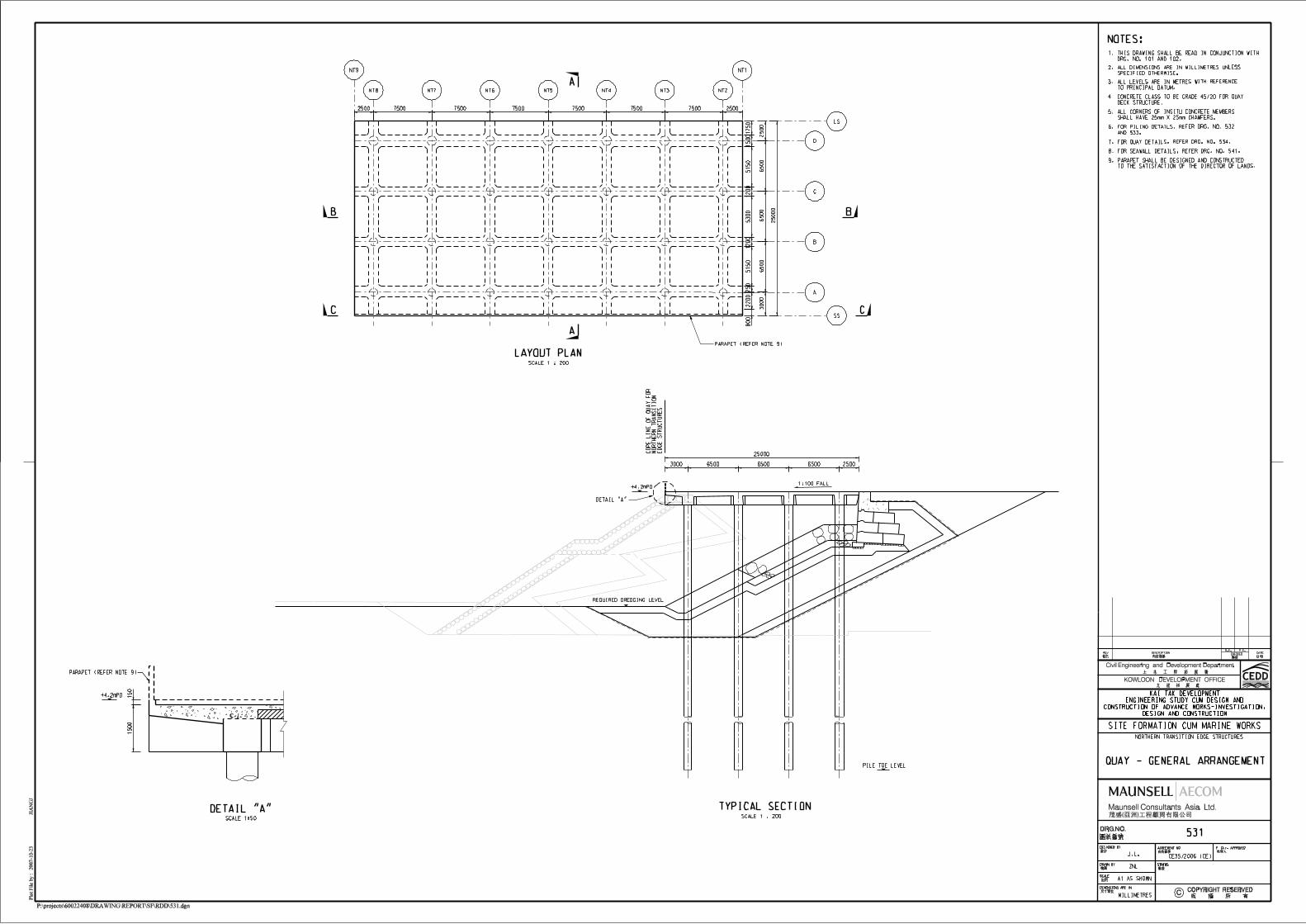
3.2.2 The Cruise Terminal Edge Structures will need to be constructed within the land limits(existing high water mark) of the existing Kai Tak runway to comply with the Protection ofHarbour Ordinance (PHO). Therefore the outer face of the fender should be aligned with theHigh Water Mark (HWM), i.e., +2.3m above Principal Datum (+2.3mPD) as defined in theDistrict Survey Office Technical Manual Version 1.1 published by Survey & Mapping Officeof Lands Department. (See Drawings 401 and 451)
Construction programme
3.2.3 Required completion date of Phase I Berth is early 2012 and this programme should beachieved to ensure the availability of the Cruise Terminal without delay.
Interface with Cruise Terminal Building construction / development
3.2.4 The Cruise Terminal Building is to be constructed next to the Edge Structures. Design andconstruction of the Edge Structures should therefore be carried out with due considerationsof the Cruise Terminal Building construction / development in order to avoid potential conflictbetween the two items of works.
Settlement which affects terminal operations and services
3.2.5 Differential settlement should be within acceptable limit, since it may affect the utilities andservices installed in the Edge Structures and the operation of mobile passenger boardingbridge.
Need for local dry dock/additional storage area for casting and transportation of precastunits
3.2.6 Establishment of a local dry dock in Hong Kong for casting and transportation of precastunits of Edge Structures, if required, may generate environmental impact whereas off-sitedry dock and additional storage area at sea adjacent to site may result in marine impactalthough it can be resolved by specific marine traffic arrangement and management. In viewof this, design proposals involving provision of a dry dock/additional storage area areconsidered not preferable.
Wave Reflection
3.2.7 The Edge Structures should be designed with a good performance in dissipation of waveenergy and reduction in wave reflection.

Agreement No. CE 35/2006(CE)Kai Tak Development Engineering Studycum Design and Construction of Advance Works Waste Management Plan for– Investigation, Design and Construction the Dredged Material from Seawall Removal
9
Maintenance disruption
3.2.8 The Edge Structures should be readily accessible for maintenance inspection and repair tominimize disruption to the operation of Cruise Terminal.
Agreement No. CE 35/2006(CE)Kai Tak Development Engineering Study
Waste Management Plan for cum Design and Construction of Advance Worksthe Dredged Material from Seawall Removal – Investigation, Design and Construction
10
4 REFERENCE DESIGN FOR EDGE STRUCTURES AND TRANSITION EDGESTRUCTURES
4.1 Introduction
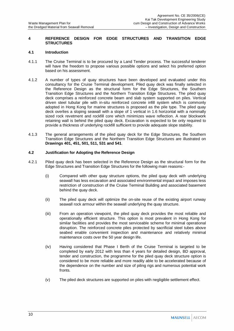
4.1.1 The Cruise Terminal is to be procured by a Land Tender process. The successful tendererwill have the freedom to propose various possible options and select his preferred optionbased on his assessment.
4.1.2 A number of types of quay structures have been developed and evaluated under thisconsultancy for the Cruise Terminal development. Piled quay deck was finally selected inthe Reference Design as the structural form for the Edge Structures, the SouthernTransition Edge Structures and the Northern Transition Edge Structures. The piled quaydeck comprises a reinforced concrete beam and slab system supported on piles. Verticaldriven steel tubular pile with in-situ reinforced concrete infill system which is commonlyadopted in Hong Kong for marine structures is proposed as the pile type. The piled quaydeck overlies a sloping seawall with a slope of 1 vertical in 1.6 horizontal with a nominallysized rock revetment and rockfill core which minimizes wave reflection. A rear blockworkretaining wall is behind the piled quay deck. Excavation is expected to be only required toprovide a thickness of underlying rockfill sufficient to provide adequate slope stability.
4.1.3 The general arrangements of the piled quay deck for the Edge Structures, the SouthernTransition Edge Structures and the Northern Transition Edge Structures are illustrated onDrawings 401, 451, 501, 511, 531 and 541.
4.2 Justification for Adopting the Reference Design
4.2.1 Piled quay deck has been selected in the Reference Design as the structural form for theEdge Structures and Transition Edge Structures for the following main reasons:-
(i) Compared with other quay structure options, the piled quay deck with underlyingseawall has less excavation and associated environmental impact and imposes lessrestriction of construction of the Cruise Terminal Building and associated basementbehind the quay deck.
(ii) The piled quay deck will optimize the on-site reuse of the existing airport runwayseawall rock armour within the seawall underlying the quay structure.
(iii) From an operation viewpoint, the piled quay deck provides the most reliable andoperationally efficient structure. This option is most prevalent in Hong Kong forsimilar facilities and provides the most serviceable scheme for minimal operationaldisruption. The reinforced concrete piles protected by sacrificial steel tubes aboveseabed enable convenient inspection and maintenance and relatively minimalmaintenance costs over the 50 year design life.
(iv) Having considered that Phase I Berth of the Cruise Terminal is targeted to becompleted by early 2012 with less than 4 years for detailed design, BD approval,tender and construction, the programme for the piled quay deck structure option isconsidered to be more reliable and more readily able to be accelerated because ofthe dependence on the number and size of piling rigs and numerous potential workfronts.
(v) The piled deck structures are supported on piles with negligible settlement effect.

Agreement No. CE 35/2006(CE)Kai Tak Development Engineering Studycum Design and Construction of Advance Works Waste Management Plan for– Investigation, Design and Construction the Dredged Material from Seawall Removal
11
(vi) The cost of the piled quay structure is low and just slightly higher than the lowestcost of other quay structure options.
(vii) The piled quay deck overlies a sloping seawall which provides a better performancein dissipation of wave energy and reduction in wave reflection than the waveabsorbing chamber for the gravity options.
(viii) The piled deck option is therefore more favorable for berthing operation of vesselsas the seawall under deck gives better performance on wave reduction and providemore space to displace the water volume when the vessel is berthing towards thequay structures.
4.3 Estimated Quantities of C&D Materials Generated and Imported Fill MaterialsRequired for Reference Design
4.3.1 Existing seawall along the runway is required to be dredged to facilitate the construction ofthe Edge Structures of the Cruise Terminal. In the Reference Design, the new slopingseawall of the Edge Structures would be provided with sufficient thickness of rockfill andarmour layer depending on the stability condition. The new seawall underlying the quaydeck provides an opportunity to utilize the armour, rockfill and general fill of the existingseawall.
4.3.2 The estimated quantities of C&D materials to be generated, reused and disposed offsitearising from the dredging works required for the construction of the Phase I Edge Structures,the Phase II Edge Structures, the Southern Transition Edge Structures and the NorthernTransition Edge Structures are summarized in Table 4.4.
Table 4.4 Estimated Quantities of C&D Materials Generated and Fill MaterialsRequired for the Edge Structures, the Southern Transition EdgeStructures and the Northern Transition Edge Structures (includingSeawall Reconstruction)
Item Estimated QuantityVolume of dredged materials 256,100 m3
Volume of materials reused in seawallconstruction 213,110 m3
Volume of materials reused in works otherthan seawall construction or disposedoffsite
42,990 m3
Additional fill materials required 231,490 m3
Notes:(1) Please refer to the Notes of Table 5.1 below for detailed description of the above estimated quantities.
4.4 Suitability of Recycling Hard C&D Materials and/or Sorting of C&D Materials on Site
4.4.1 Based on the as-built drawings, on-site inspection and site investigation results, it isanticipated that the majority of the rock armour dredged from the existing runway seawall isof suitable size and condition and can be sorted and re-used in the new seawall revetmentof the piled deck option. As regards rockfill, the portion of the dredged materials which aresuitable for re-use is expected to be generally lesser given the increased difficulty in sortingthese finer materials to meet the required size and grading for re-use. As for general fill,since the grading requirement is generally less stringent than that of rockfill, the percentageof re-use is expected to be higher than that of rockfill.

Agreement No. CE 35/2006(CE)Kai Tak Development Engineering Study
Waste Management Plan for cum Design and Construction of Advance Worksthe Dredged Material from Seawall Removal – Investigation, Design and Construction
12
5 MANAGEMENT OF C&D MATERIALS
5.1 Generation and Reuse of C&D Materials
5.1.1 C&D materials will be generated from dredging of existing seawall to provide adequatewater depth in the berth box and to allow for the construction of the seawall revetment underthe piled quay deck of the Edge Structures, the Southern Transition Edge Structures andthe Northern Transition Edge Structures for the Cruise Terminal. These C&D materials willbe primarily granular in nature, comprising mainly rock armour, granular fill and general fill.
5.1.2 The major construction activity which requires large quantities of fill material is theconstruction of the seawall revetment below the piled quay deck of the Edge Structures, theSouthern Transition Edge Structures and the Northern Transition Edge Structures for theCruise Terminal. The fill materials required include rock armour, rock fill, filter and general fill.
5.1.3 Considerations have been taken in development of the Reference Design to maximizereuse of the C&D materials generated from dredging of existing seawall. The existing rockarmour from the runway seawall will be reused in the proposed seawall revetment subject tothe actual sizes and conditions of the rock armour. The rockfill mound of the existingseawall will be reused as rockfill core for the new seawall and the reclamation fill of therunway behind the rockfill mound of the existing seawall will be used as general fill materialfor the proposed seawall subject to the actual sizes and conditions of the dredged materials.
5.1.4 The dredged materials which are suitable for reuse including the armour, rockfill and generalfill will be screened, sorted and stockpiled at a temporary stockpiling area. This stockpilingarea is estimated to be approximately 1.5 hectares during the peak period. Based on theenvisaged programme, the peak period for stockpiling of the dredged materials would occurin second half of 2009 when construction of the new seawall revetment will have justcommenced. Since there will be other concurrent construction activities to be constructed inparallel with the Edge Structures, the temporary stockpiling area may be reduced by betterprogramming of the concurrent construction activities. The surplus materials would bedisposed to the public fill site(s) designated by the Pubic Fill Committee. It is anticipated thatthe surplus materials would be disposed via land route after sorting on site. To monitor thedisposal process, a trip-ticket system should be included as one of the contractualrequirements. Existing public fill reception facilities available to the public include: (i) TseungKwan O Area 137 Fill Bank; (ii) Quarry Bay Temporary Public filling barging point (iii) MuiWo Temporary Public fill Reception Facility and (iv) Tuen Mun Area 38 Fill Bank. Of thesepublic fill reception facilities, Tseung Kwan O Area 137 Fill Bank is the nearest one to theCruise Terminal site.
5.1.5 Provided that the temporary stockpiling area of about 1.5 hectares is available, theestimated total volume of different types of C&D materials generated, reused & disposedarising from dredging of the existing seawall and the total volume of different types of fillmaterials (including additional fill materials required) required for construction of the EdgeStructures, the Southern Transition Edge Structures and the Northern Transition EdgeStructures including the new seawall revetment based on the Reference Design aresummarized in the Table 5.1 below. Based on a preliminary review, about 1.5 hectare areacould be accommodated within the project site, yet the location and the final arrangementwould be subject to the detailed construction site arrangement to be formulated andimplemented by the successful tenderer. An indicative location of the temporary stockpilingarea is shown in Figure F4.2. Alternatively, the successful tenderer may consider applyingfor an alternative stockpiling area outside the Cruise Terminal lot boundary subject to landavailability and compliance with relevant environmental protection requirements. Thebreakdown for the estimation of the quantities of C&D materials is provided in Appendix A.Please however note that the actual quantities of the C&D materials generated and theadditional fill materials required are subject to the design and construction methods to beadopted by the successful tenderer. Mitigation measures and good site practices should beimplemented to control potential environmental impact from handling and transportation of

Agreement No. CE 35/2006(CE)Kai Tak Development Engineering Studycum Design and Construction of Advance Works Waste Management Plan for– Investigation, Design and Construction the Dredged Material from Seawall Removal
13
C&D material including those activities associated with the temporary stockpile inaccordance with the Air Pollution Control (Construction Dust) Regulation and EPD’sPractice Note for Professional Persons on Construction Site Drainage (ProPECC PN1/94). Mitigation measures of particular relevance to temporary stockpile include:
Temporary stockpile if any shall be located away from waterfront or storm drains as faras possible.
Open stockpiles of construction materials or construction wastes on-site should becovered with tarpaulin or similar fabric.
Skip hoist for material transport should be totally enclosed by impervious sheeting.
All dusty materials should be sprayed with water prior to any loading, unloading ortransfer operation so as to maintain the dusty materials wet.
The height from which excavated materials are dropped should be controlled to aminimum practical height to limit fugitive dust generation from unloading.
Table 5.1 Summary of C&D materials Generated, Reused & Disposed arising fromthe Dredging Works required for the Construction of Edge Structures ,Southern Transition Edge Structures and Northern Transition EdgeStructures (including Seawall Re-construction)
Type of Materials Dredged(see note 1)
Required(see note 2)
Reused inSeawall
Construction(see note 3)
Reused inWorks otherthan SeawallConstruction
orDisposed
Offsite(see note 4)
AdditionalFill Materials
Required(see note 5)
Grade II orabove rock
RockArmour 56,900 74,800 56,900 0 17,900
Rock fill 143,300 248,600 100,310 42,990 148,290Grade III orbelow rock Filter 0 48,500 0 0 48,500Inert soft C&Dmaterials
GeneralFill 55,900 72,700 55,900 0 16,800
Total 256,100 444,600 213,110 42,990 231,490Notes:(1)These figures refer to the amounts of C&D materials generated from dredging only which does not includeexcavation within land limits.(2)These figures refer to the quantities of fill materials required for construction of the whole new seawall revetment.(3)These figures refer to the quantities of the dredged C&D materials to be re-used for construction of the newseawall revetment.(4)These figures refer to the quantities of surplus or unsuitable dredged materials which cannot be re-used inconstruction of the new seawall revetment and need to be re-used in other areas of the Cruise Terminal site ordisposed of offsite.(5)These figures refer to the outstanding quantities of the fill materials required for construction of the new seawallrevetment after re-using all available dredged C&D materials. The outstanding required quantities can either besupplied by (i) re-using surplus excavated C&D materials generated from land excavation of the existing seawall orother parts of the Cruise Terminal site; or (ii) by importing the required fill materials from off-site sources.

Agreement No. CE 35/2006(CE)Kai Tak Development Engineering Study
Waste Management Plan for cum Design and Construction of Advance Worksthe Dredged Material from Seawall Removal – Investigation, Design and Construction
14
5.2 Programme of Generation and Reuse of C&D Materials
5.2.1 Based on the envisaged implementation programme shown in Figure F4.1, the schedule ofquantities of C&D materials generated and reused and the additional fill materials requiredare shown in Appendix B. Please however note that this programme is based on theReference Design only and the actual programme is subject to the design and constructionmethod to be adopted by the successful tenderer.

Agreement No. CE 35/2006(CE)Kai Tak Development Engineering Studycum Design and Construction of Advance Works Waste Management Plan for– Investigation, Design and Construction the Dredged Material from Seawall Removal
15
6 CONCLUSION AND RECOMMENDATION
6.1 Summary and Conclusion
6.1.1 The amounts of generation and reuse of C&D materials estimated in this report are basedon the Reference Design and the envisaged implementation programme only. Thesuccessful tenderer has the freedom to propose various possible options and select hispreferred option which may result in different amounts of generation and reuse of C&Dmaterials.
6.1.2 A number of options for the Edge Structures, the Southern Transition Edge Structures andthe Northern Transition Edge Structures of the Cruise Terminal have been developed andreviewed in arriving at the selected option in Reference Design – the piled quay deck.Generation and re-use of C&D materials have been considered as one of the keyassessment criteria during the evaluation process.
6.1.3 Based on the Reference Design, It is estimated that a total of 256,100 m3 of C&D materialswould be generated from dredging of existing seawall. Of these C&D materials,approximately 22% of the C&D materials is inert soft C&D materials. Approximately 22% isGrade II or above rock, and approximately 56% is Grade III or below rock.
6.1.4 Measures have been taken in both design, programming of the works and arrangement oftemporary stockpiling area to maximize re-use of the dredged C&D materials. Approximately213,110 m3 of the dredged materials1 would be re-used in the new construction, whichaccounts for about 83% of the all dredged materials, subject to actual sizes and conditionsof the dredged materials. The assumptions on the percentages of re-use are 100% for thedredged Grade II or above rock, 70% for the dredged Grade III or below rock, and 100% forthe dredged inert soft C&D materials.
6.1.5 It is expected that the surplus materials would be disposed off site during period from May2009 to May 2012. The additional fill materials would be required from October 2009 toAugust 2012. Please however note that the actual quantities of the C&D materialsgenerated and the additional fill materials required, as well as the actual programme ofdisposal / requirement of the C&D materials are subject to the design and constructionmethods to be adopted by the successful tenderer.
6.2 Recommendation
6.2.1 The following measures are recommended to minimize generation of surplus C&D materials:
Programming of Construction Activities
6.2.2 Construction activities involving generation and re-use of C&D materials should be betterprogrammed to minimize the temporary stockpiling area and time required, thus minimizingthe works area constraint and possible environmental impact arising from the re-use of thegenerated C&D materials.
Site Management and Operation Practice
6.2.3 Operation procedures and site practices should be established and implemented for theoperation of construction activities and management of C&D materials generated on site.The established procedures for relevant construction operations including dredging,handling of dredged materials, storage and stockpiling of C&D materials and transportationof the C&D materials should be strictly implemented on site in order to preventcontamination of the C&D materials and to ensure the of C&D materials are in satisfactionquality suitable for reuse and recycling purpose.

Agreement No. CE 35/2006(CE)Kai Tak Development Engineering Study
Waste Management Plan for cum Design and Construction of Advance Worksthe Dredged Material from Seawall Removal – Investigation, Design and Construction
16
- End -

Appendices

Final Working Paper on Construction and Demolition Material Management for Dredging Works for Proposed Cruise Terminal at Kai TakAppendix A - Breakdown for Estimation of Quantities of C&D Materials
Dredged
Item No. (1) (2) (3) (4) (5) = (2)+(3)+(4) (6) = (1)*(5)
Item Sectional Area Length of Edge StructuresLength of Northern
Transition Edge StructuresLength of Southern
Transition Edge StructuresTotal Length Estimated Quantities
Rock Armour 54 850 50 153 1053 56862
Rock fill 136 850 50 153 1053 143208
Filter 0 850 50 153 1053 0
General Fill 53 850 50 153 1053 55809
Required
Item No. (1) (2) (3) (4) (5) = (2)+(3)+(4) (6) = (1)*(5)
Item Sectional Area (m2) Length of Edge StructuresLength of Northern
Transition Edge StructuresLength of Southern
Transition Edge StructuresTotal Length Estimated Quantities
Rock Armour 71 850 50 153 1053 74763
Rock fill 236 850 50 153 1053 248508
Filter 46 850 50 153 1053 48438
General Fill 69 850 50 153 1053 72657
Note: Please refer to the attached Sketch 1 showing the extent of the above Sectional Areas.


Agreement No. CE 35/2006(CE)Kai Tak Development Engineering Studycum Design and Construction of Advance WorksInvestigation, Design and Construction
Waste Management Plan for the Dredged Material from Seawall Removal
Appendix B - Schedule of Quantities of C&D materials Generated and Reused and Additional Fill Materials Required
Dredging TotalJan Feb Mar Apr May Jun Jul Aug Sep Oct Nov Dec Jan Feb Mar Apr May Jun Jul Aug Sep Oct Nov Dec Jan Feb Mar Apr May Jun Jul Aug Sep Oct Nov Dec Jan Feb Mar Apr May Jun Jul Aug
Rock Armour 2364 2364 2364 2364 2364 2364 2364 2364 2364 2364 2364 2364 2364 1091 1091 1091 1091 1091 1091 1091 1091 1091 1091 1091 1091 1091 1091 1091 1091 1091 1091 1091 1091 1091 1091 1091 1091 0 0 0 0 56900Rock fill 5952 5952 5952 5952 5952 5952 5952 5952 5952 5952 5952 5952 5952 2747 2747 2747 2747 2747 2747 2747 2747 2747 2747 2747 2747 2747 2747 2747 2747 2747 2747 2747 2747 2747 2747 2747 2747 0 0 0 0 143300Filter 0 0 0 0 0 0 0 0 0 0 0 0 0 0 0 0 0 0 0 0 0 0 0 0 0 0 0 0 0 0 0 0 0 0 0 0 0 0 0 0 0 0General Fill 2322 2322 2322 2322 2322 2322 2322 2322 2322 2322 2322 2322 2322 1071 1071 1071 1071 1071 1071 1071 1071 1071 1071 1071 1071 1071 1071 1071 1071 1071 1071 1071 1071 1071 1071 1071 1071 0 0 0 0 55900Total 10638 10638 10638 10638 10638 10638 10638 10638 10638 10638 10638 10638 10638 4909 4909 4909 4909 4909 4909 4909 4909 4909 4909 4909 4909 4909 4909 4909 4909 4909 4909 4909 4909 4909 4909 4909 4909 0 0 0 0 256100
Required TotalJan Feb Mar Apr May Jun Jul Aug Sep Oct Nov Dec Jan Feb Mar Apr May Jun Jul Aug Sep Oct Nov Dec Jan Feb Mar Apr May Jun Jul Aug Sep Oct Nov Dec Jan Feb Mar Apr May Jun Jul Aug
Rock Armour 2020 4039 4039 4039 4039 4039 4039 4039 4039 4039 2020 748 1496 1496 1496 1496 1496 1496 1496 1496 1496 1496 1496 1496 1496 1496 1496 1496 1496 1496 1496 1496 1496 1496 748 74800Rock fill 6712 13424 13424 13424 13424 13424 13424 13424 13424 13424 6712 2486 4972 4972 4972 4972 4972 4972 4972 4972 4972 4972 4972 4972 4972 4972 4972 4972 4972 4972 4972 4972 4972 4972 2486 248600Filter 1310 2619 2619 2619 2619 2619 2619 2619 2619 2619 1310 485 970 970 970 970 970 970 970 970 970 970 970 970 970 970 970 970 970 970 970 970 970 970 485 48500General Fill 1963 3926 3926 3926 3926 3926 3926 3926 3926 3926 1963 727 1454 1454 1454 1454 1454 1454 1454 1454 1454 1454 1454 1454 1454 1454 1454 1454 1454 1454 1454 1454 1454 1454 727 72700Total 12004 24008 24008 24008 24008 24008 24008 24008 24008 24008 12004 4446 8892 8892 8892 8892 8892 8892 8892 8892 8892 8892 8892 8892 8892 8892 8892 8892 8892 8892 8892 8892 8892 8892 4446 444600
Reused in Seawall Construction TotalJan Feb Mar Apr May Jun Jul Aug Sep Oct Nov Dec Jan Feb Mar Apr May Jun Jul Aug Sep Oct Nov Dec Jan Feb Mar Apr May Jun Jul Aug Sep Oct Nov Dec Jan Feb Mar Apr May Jun Jul Aug
Rock Armour 2020 4039 4039 4039 4039 4039 4039 4039 1523 1091 1091 748 1433 1091 1091 1091 1091 1091 1091 1091 1091 1091 1091 1091 1091 1091 1091 1091 1091 1091 1091 1091 0 0 0 56900Rock fill 6712 13424 13197 4167 4167 4167 4167 4167 1923 1923 1923 1923 1923 1923 1923 1923 1923 1923 1923 1923 1923 1923 1923 1923 1923 1923 1923 1923 1923 1923 1923 1923 0 0 0 100310Filter 0 0 0 0 0 0 0 0 0 0 0 0 0 0 0 0 0 0 0 0 0 0 0 0 0 0 0 0 0 0 0 0 0 0 0 0General Fill 1963 3926 3926 3926 3926 3926 3926 3926 1814 1071 1071 727 1416 1071 1071 1071 1071 1071 1071 1071 1071 1071 1071 1071 1071 1071 1071 1071 1071 1071 1071 1071 0 0 0 55900Total 10695 21389 21162 12132 12132 12132 12132 12132 5259 4085 4085 3398 4772 4085 4085 4085 4085 4085 4085 4085 4085 4085 4085 4085 4085 4085 4085 4085 4085 4085 4085 4085 0 0 0 213110
Reused in Other Works or Disposed TotalJan Feb Mar Apr May Jun Jul Aug Sep Oct Nov Dec Jan Feb Mar Apr May Jun Jul Aug Sep Oct Nov Dec Jan Feb Mar Apr May Jun Jul Aug Sep Oct Nov Dec Jan Feb Mar Apr May Jun Jul Aug
Rock Armour 0 0 0 0 0 0 0 0 0 0 0 0 0 0 0 0 0 0 0 0 0 0 0 0 0 0 0 0 0 0 0 0 0 0 0 0 0 0 0 0 0Rock fill 1786 1786 1786 1786 1786 1786 1786 1786 1786 1786 1786 1786 1786 824 824 824 824 824 824 824 824 824 824 824 824 824 824 824 824 824 824 824 824 824 824 824 824 0 0 0 42990Filter 0 0 0 0 0 0 0 0 0 0 0 0 0 0 0 0 0 0 0 0 0 0 0 0 0 0 0 0 0 0 0 0 0 0 0 0 0 0 0 0 0General Fill 0 0 0 0 0 0 0 0 0 0 0 0 0 0 0 0 0 0 0 0 0 0 0 0 0 0 0 0 0 0 0 0 0 0 0 0 0 0 0 0 0Total 1786 1786 1786 1786 1786 1786 1786 1786 1786 1786 1786 1786 1786 824 824 824 824 824 824 824 824 824 824 824 824 824 824 824 824 824 824 824 824 824 824 824 824 0 0 0 42990
Additional Fill Materials Required TotalJan Feb Mar Apr May Jun Jul Aug Sep Oct Nov Dec Jan Feb Mar Apr May Jun Jul Aug Sep Oct Nov Dec Jan Feb Mar Apr May Jun Jul Aug Sep Oct Nov Dec Jan Feb Mar Apr May Jun Jul Aug
Rock Armour 0 0 0 0 0 0 0 0 2517 2949 929 0 63 405 405 405 405 405 405 405 405 405 405 405 405 405 405 405 405 405 405 405 1496 1496 748 17900Rock fill 0 0 227 9258 9258 9258 9258 9258 11502 11502 4790 563 3049 3049 3049 3049 3049 3049 3049 3049 3049 3049 3049 3049 3049 3049 3049 3049 3049 3049 3049 3049 4972 4972 2486 148290Filter 1310 2619 2619 2619 2619 2619 2619 2619 2619 2619 1310 485 970 970 970 970 970 970 970 970 970 970 970 970 970 970 970 970 970 970 970 970 970 970 485 48500General Fill 0 0 0 0 0 0 0 0 2112 2854 891 0 38 383 383 383 383 383 383 383 383 383 383 383 383 383 383 383 383 383 383 383 1454 1454 727 16800Total 1310 2619 2846 11877 11877 11877 11877 11877 18749 19924 7920 1048 4120 4807 4807 4807 4807 4807 4807 4807 4807 4807 4807 4807 4807 4807 4807 4807 4807 4807 4807 4807 8892 8892 4446 231490
Note:
The programme and quantities shown above are based on the Reference Design only and the actual programme and quantities are subject to the design and construction method to be adopted by the successful tenderer.
2009 2010
2009 2010 2012
2009 2010
2012
2012
2011
2011
2011
2009 2010 2012
2009 2010 20122011
2011


ID Task Name
1 Site Formation cum Marine Works
2 Award of CT Contract
3 Design, Approval and Tendering
4 Construction Period
5 Commencement of Construction
6 Phase I Berth Related Construction Works
7 Southern Transition Edge Structures
8 Phase I Edge Structures
9 Phase I Apron Facilities
10 Removal of Existing Abandoned Submarine Outfall
11 Phase II Berth Related Construction Works
12 Northern Transition Edge Structures
13 Phase II Edge Structures
14 Phase II Apron Facilities
Q1 Q2 Q3 Q4 Q1 Q2 Q3 Q4 Q1 Q2 Q3 Q4 Q1 Q2 Q3 Q4 Q1 Q2 Q3 Q4 Q1 Q2 Q3 Q42008 2009 2010 2011 2012 2013
Task Split Milestone Summary
Agreement No. CE 35/2006KTD Engineering Study cum Design and Construction of Advance Works
Envisaged Implementation Programme for Edge Structures, Southern Transition Edge Structures and Northern Transition Edge Structures Figure F4.1
