investigation of deployable structures and their actuation
TRANSCRIPT
Investigation of Deployable Structures and
Their Actuation
by
Logan Munro
SUBMITTED TO THE DEPARTMENT OF MECHANICAL ENGINEERING INPARTIAL FULFILLMENT OF THE REQUIREMENTS FOR THE DEGREE OF
BACHELOR OF SCIENCE
at the
MASSACHUSETTS INSTITUTE OF TECHNOLOGY
May 2007
©2007 Logan Munro. All rights reserved
The Author hereby grants to MIT permission to repro-duce and to distribute publicly paper and electroniccopies of this thesis document in whole or in part.
Signature of Author:
Certified by:
Accepted By:
MASSACHUSETTS INSTrT'OF TECHNOLOGY
JUN 2 12007
Department of Mechanical EngineeringMay 11, 2007
Anette E. HosoiAssociate Professor of Mechanical Engineering
SThesis Supervisor
John. H. Lienhard VChairman, Undergraduate Thesis Committee
ARCHiVES
-- v , -
1

~
3
Investigation of Deployable Structuresand Their Actuation
by
Logan Munro
Submitted to the Department of Mechanical Engineering onMay 11, 2007 in partial fulfillment of the requirements for the
Degree of Bachelor of Science in Mechanical Engineering
ABSTRACTDeployable Structures had not been designed for use in the oil field industry,and additionally have not been designed as devices to perform mechanicalwork. By analyzing deployable structures a detailed understanding of themechanism kinematics has been developed. Further, we have analyzed newdesign concepts of deployable structures that include void filling alterationsand snap fit strengthening. The actuation and mechanical loading of the struc-tures and the input to output force ratio were investigated. This understandingwas applied to several actuation methods.
Thesis Supervisor: Anette E. HosoiTitle: Associate Professor of Mechanical Engineering

-g

1. ACKNOWLEDGEMENTS
I would like to thank Dr. Julio Guerrero for his incredible efforts in advising me during
the production of this thesis and beyond, and for exposing me to oil field research. I
would also like to thank Schlumberger for supporting this thesis.

g,
CONTENTS1. ACKNOW LEDGEMENTS ............................................................................................. 5
2. INTRODUCTION ............................................................................................................. 11
2.1 Deployable structure definition .................................................... 112.2 Background and Objectives ................................................................................. 11
3. ANALYSIS OF PRIOR ART .............................................................. 12
3.1 Deployable structures in academia ......................................... ............. 123.2 Oilfield related ..................................................................... ............................. 133.3 Compliant m echanism s ........................................ ............................................. 133.4 Biom edical .............................................................................................................. 13
3.5 Conclusions about previous art .................................................. 14
4. CONCEPT AND MODELING ............................................................. 14
4.1 Deployable structure concept................................................. 154.2 M odeling ................................................................................................................. 154.3 Kinem atics .............................................................................................................. 18
5. EMBODIMENT DETAILS ........................................................ ...................................... 20
5.1 Shape........................................ ....................................................................... 20
5.2 Snap fit.................................................................................................................... 20
5.3 M anufacture .................................................. .................................................... 21
6. ACTUATION AND DEPLOYMENT ................................................................................. 22
6.1 Description of actuation systems: ................................................................ 226.2 Conclusion of actuation m echanism s .......................................................... 26
7. CONCLUSION ................................................................................................................. 26
8. REFERENCES ................................................................................................................. 27
9. APPENDIX A ................................................. 28
LIST OF FIGURESFIGURE 1 IMPLEMENTED USES OF DEPLOYABLE STRUCTURES ............................................. 29
FIGURE 2 "EXPANDABLE/COLLAPSIBLE STRUCTURES-A" PATENT ........................................ 29
FIGURE 3 "METHOD AND SYSTEM FOR REDUCING LONGITUDINAL FLUID FLOW
AROUND A PERMEABLE WELL," SHELL PATENT.................................. .......... 30
FIGURE 4 "CONTRACTABLE [SIC] AND EXPANDABLE TUBULAR WELLBORE SYSTEM,"SHELL PATENT ...................................... .................................... 30
FIGURE 5 "FOLDABLE TUBE, " SHELL PATENT ...................................................................... 31
FIGURE 6 "EXPANDABLE WELLBORE ASSEMBLY, " SHELL PATENT ........................................ 31
FIGURE 7 GENERIC STRUCTURE OF EXPANDABLE STRUCTURE ...................................... 32
FIGURE 8 EXPANSION RATIO FIGURE ........................................... ............... 32
FIGURE 9 DEPLOYABLE STRUCTURE UNDER ACTUATION AND OPPOSING FORCES ..............33
FIGURE 10 SCISSOR MECHANISM EXAMPLE; LAZY TONGS ......................................... 33
FIGURE 11 SCHEMATIC SHOWING SCISSOR LINKAGE ..................................... ........ 34
FIGURE 12 CYLINDRICAL CO-ORDINATES ......................................... ............. 34
FIGURE 13 TWO MODES OF CIRCUMFERENTIAL EXPANSION IN CYLINDRICAL CO-
ORDINATES ........................................... ............................................................... 35
FIGURE 14 AN ANGULATED ELEMENT ............................................ .............. 35
FIGURE 15 A SINGLE PETAL CONNECTED AT ONE JOINT...................................36
FIGURE 16 SIMPLIFIED EQUATION OF DIAMETER FOR A CONTRACTED DEPLOYABLE
STRUCTURE ........................................................... ............... ....................... 36
FIGURE 17 SIMPLIFIED EQUATION OF DIAMETER FOR AN EXPANDED DEPLOYABLE
STRUCTURE ............................................................ ............... ....................... 37
FIGURE 18 SIMPLEST ANGULATED ELEMENT WHERE N = 2.................................... ... 37
FIGURE 19 THE THREE LABEL JOINTS OF AN ANGULATED ELEMENT ................................. 38
FIGURE 20 EXPANSION STATES 1, 2 AND 3 ........................................... ....... 38
FIGURE 21 EXPANSION BY VERTEX GRAPH...................................... .............. 39
FIGURE 22 GRAPH OF FORCE TRANSMISSION RATIO AS A FUNCTION OF INNER
DIAMETER AND DEVICE SIZE................................. ........................... 40
FIGURE 23 LAYERED, GAPLESS PROTOTYPE .......................................................................... 41
8

FIGURE 24 STRAIGHT LINK DS ITERATION .......................................... .......... 41
FIGURE 25 CURVED LINK DS ITERATION..................................................42
FIGURE 26 THICKENED LINK DS ITERATION ........................................ .......... 42
FIGURE 27 ARCH.......................................................................... ....................................... 42
FIGURE 28 'VARIOUS SNAP FIT TYPES. ............................................ ........... 43
FIGURE 29 RELEASING AND NON-RELEASING SNAP FITS. ..................................... .... 43
FIGURE 30 SINGLE SNAP FIT ........................................... ............................................... 44
FIGURE 31 RATCHET SNAP ........................................... ................................................. 44
FIGURE 32 INDIVIDUAL ELEMENT .......................................................... 45
FIGURE 33 ALTERED JOINT SHAPES OF ANGULATED ELEMENTS. ........................................ 45
FIGURE 34 SCHEMATIC OF DSCFX D.................................................................................... 46
FIGURE 35 SCHEMATIC OF DISCRoTATooN............................................................................... 46
FIGURE 36 TIME-LAPSE OF ROTATING SPIRAL DISC ON STATIONARY DISC .......................... 46
FIGURE 37 ANNOTATED ROTATIONAL DEVICE. ........................................ ....... 47
FIGURE 38 COMPARISON OF INCREASED PATH LENGTH SPIRAL (LEFT) TO SHORT PATHLENGTH (RIGHT)............................................... .................................................... 47
FIGURE 39 INTERNAL AND EXTERNAL USE GEARED ACTUATION MECHANISM .................. 48
FIGURE 40 MIULTI-FUNCTIONAL GEARED MECHANISM ..................................................... 48
FIGURE 41 SCHEMATICS OF INTERNAL AND EXTERNAL EXTENDED ARMS DEVICEACUTATION. ........................................................................... ............................... 49
FIGURE 42 DETAIL OF A PISTON-ACTUATED DEPLOYMENT METHOD. ............................... 49
FIGURE 43 DETAIL OF THREADED-ROD ACTUATED DEVICE ....................................... 50
FIGURE 44 PEAUCELLIER-LIPKIN LINKAGE SCHEMATIC. ......................................... 50
FIGURE 45 EXTERNALLY PLACE PEAUCELLIER-LIPKIN LINKAGE. ....................................... 51
FIGURE 46 INTERNALLY PLACE PEAUCELLIER-LIPKIN LINKAGE. ........................................ 51

2. INTRODUCTION
2.1 Deployable structure definition
A Deployable Structure (DS) is any mechanism that can expand from enclosing a small
area or volume to enclosing a larger area or volume. DS combine rigid linkages and joints
in a configurable closed-loop mechanism; see Figure 1 for examples.
2.2 Background and Objectives
Downhole operations in oil field exploration require tools to convey material to the well
wall, and tools that perform mechanical work. Most mechanical systems in the downhole
environment convey parts radially by employing mechanisms such as sliders and pin
joints distributed around the diameter of a tool. Deployable structures have the ability to
solve some of the inherent faults seen in these traditional linkages and provide functional
advantages of these mechanisms. A DS can transform a collapsed disc structure into an
expanded ring several times larger than the initial diameter. Deployable structures can
convey material into a cylindrical shape. DS have not as of yet been used to perform me-
chanical work either in the downhole environment or elsewhere. This work investigates
the use of deployable structures performing mechanical work and the force advantages
that can be generated. Methods of expanding DS have been proposed that will allow the
use of DS downhole for these and other applications.
An alternative structure capable of conveying material radially is the compliant mecha-
nism. With respect to compliant structures, a DS can achieve a greater range of expansion
with a more robust design, suitable for the harsh environment found down-well. (Guer-
rero et al. [01])
By exploring the existing knowledge and embodiments of expandable mechanisms and
how they relate to deployable structures, this report investigates the generic implementa-
tion of a deployable structure. Through an understanding of the deployable structure
kinematics, we are able to describe actuation methods that exist and can be useful for
downhole applications. These actuation methods have been patented by Schlumberger
(Guerrero and Munro [02]).

The report analyzes the previous work of deployable structures and develops parametric
equations to describe the motion and force generation capabilities of DS. From this, an
understanding of the forces developed and transmitted is tackled, followed by computer
simulations and design of deployable structures. Finally, existing actuation methods are
investigated and explained.
3. ANALYSIS OF PRIOR ART
The current uses of deployable structures are primarily limited to conveying material
outwards, or for entertainment or for aesthetic functions. Deployable structures are seen
in a limited variety of products such as camera apertures, children's toys, storage con-
tainers, sculptures and retractable roofing. None of these implementations contain an
integrated actuation mechanism, nor are they used to transfer forces or perform work.
This section investigates existing research in deployable structures based primarily in
academia and relevant research and patents in the oil-field industry.
3.1 Deployable structures in academia
The inventions of Professor Sergio Pellegrino [03] have been studied for their ingenuity
with regard to deployable structures. Hoberman [04], [05], [06], [07] and [08] holds sev-
eral patents in the area of collapsible structures in addition to Zeigler [09]. These
inventions are all variations of foldable structures that cover some spherical surface.
Pelligrino's "Expandable/collapsible Structures", [03] is the closest prior art to the
mechanism investigated in this report. However - for use as a downhole structure - the
device proposed in Pelligrino's patent has the following shortcomings:
a) the device is not capable of adjusting its deployed-state perimeterto the inner perimeter of the cylindrical space where it is deployed,
b) the device cannot be locked in a deployment state,
c) the device does not provide a means by which to actuate and de-ploy the structure,
d) the device has not been developed to transmit forces or performwork.
Figure 2 shows two different inner perimeters achieved by Pellegrino's invention, illus-
trating that a variety of closed loop shapes are possible and differences in configuration
that can be produced from a simple repeated structure.
3.2 Oilfield related
An extensive search of previous patents related to deployable structures revealed there is
limited prior art in the field. Shell has produced the most inventions of oilfield related
expanding elements in down-hole environments. Out of 1000 patents, none describe de-
ployable structures; instead Shell's patents all describe tubular systems that are deformed
plastically or elastically, but they are not mechanisms, see Figure 3, Figure 4, Figure 5,
Figure 6 and appendix A.
3.3 Compliant mechanisms
There have been other attempts to develop expandable systems that adjust and conform
their perimeter to the inner perimeter of a cylindrical space where deployed. Some of
these have used compliant mechanisms that expand and collapse in order to cover differ-
ent geometries and areas. Some of these attempts are: "Compliant mesh structure for
collapsible reflector" (US patent 3982248A), "Foldable assembly of like size and shape
structural members, foldable for handling, packaging, shipping, and storage, and un-
folded and utilized as principal members of structures" (US patent 5448867A).
"Mechanical end face seal ring having a compliant seal face" (US patent 6299173B 1),
which uses compliant elements arranged around a sealing ring, each of them deforming
like cantilever beams. "Self aligning connector bodies" (US patent 6379071B1) uses
compliant rings and dowel pins to facilitate the alignment of parts during assembly. None
of these embodiments provide details for actuation and none are designed primarily to
transfer forces or work.
3.4 Biomedical
Some interesting applications of related mechanisms have been found in biomedical de-
vices. In addition one of the devices most closely related to the examined device is
"Method and apparatus for radical prostactetomy anastomosis" (PatentI 3
WO2004000137A2 (A2,A3)), which has an inflatable anchoring module that allows it to
anchor with respect to the cylindrical surface of the organ operated upon. This system
also has devices that are expandable in the axial direction. The patent "Implantable self-
expanding prosthetic device" (US patent 20050090893A1) is a system composed of
compliant cells made of U-shape wires that conform to a circular tubular contour; it is
less stiff in the axial direction than in the radial direction which allows it to be retracted
by pulling in the axial direction.
3.5 Conclusions about previous art
It can be summarized that deployable structure related patents are focused in the follow-
ing areas: apertures, collapsible structures, bio-medical devices, and other various and
isolated applications. From all of the prior art analyzed, nothing has described the use of
deployable structures specifically for downhole use or as a method of transferring forces,
as is analyzed in this report. The prior art is missing both the application of DS as a
down-hole tool as well as the actuation mechanisms required.
4. CONCEPT AND MODELING
This section discusses the theory behind the deployable structure presented in this report,
represented in Figure 7. The general equations are presented and the results of computer
aided modeling are shown.
For the generic circular structure, the important variables to consider are the initial di-
ameter and the final diameter (Figure 8). These can be non-dimensionalized to an
expansion ratio where:
Expansion Ratio = Outer DiametergtiaExpansion Ratio =Outer Diameterfial
The actuation of the circular structure creates a leverage of forces through the mecha-
nism, (Figure 9) from the inner perimeter forces to the outer perimeter forces. This ratio
of the output force of the structure to the input force is the force ratio:

Force Ratio = o-- rceinerEForceouter
4.1 Deployable structure concept
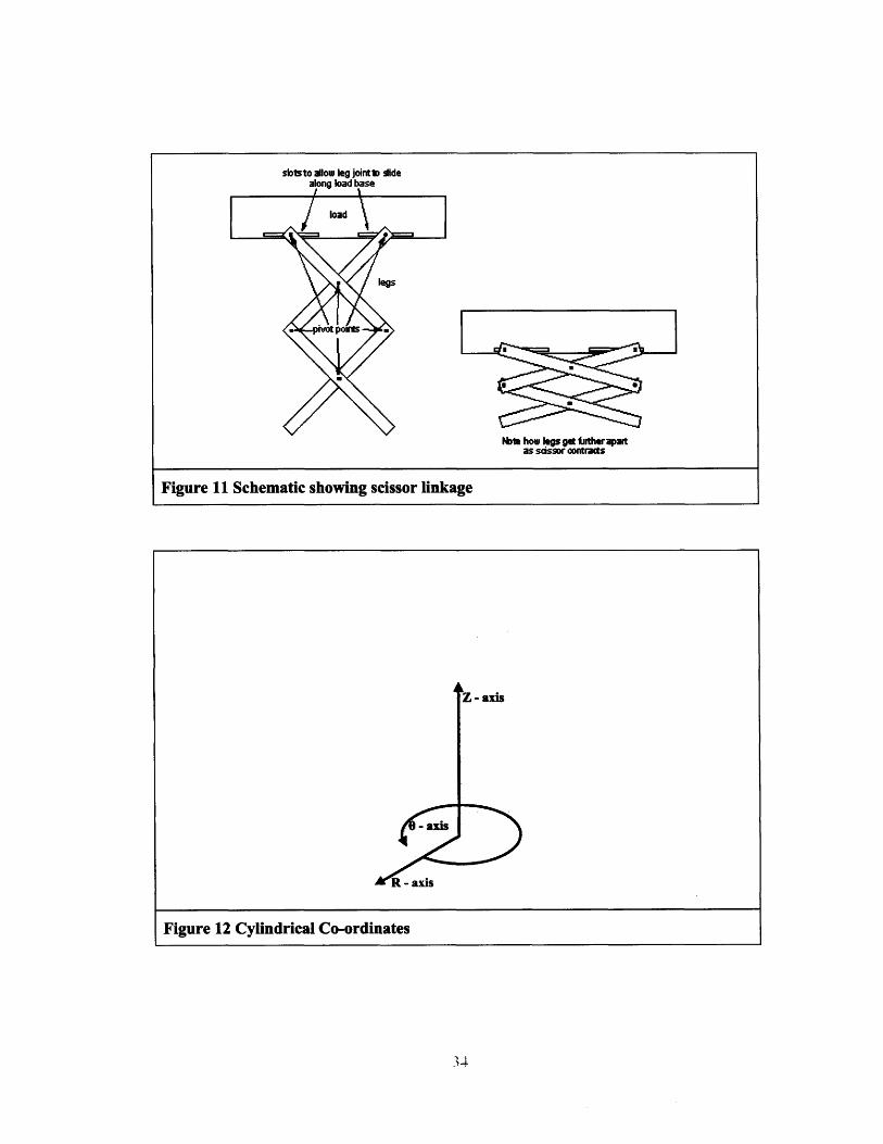
The primary element of the closed-loop deployable structure expansion is the "scissor
linkage". A scissor linkage allows for a mass transfer from one axis to another, for exam-
ple from the X axis to the Y axis in a simple lazy-tongs example, Figure 10 and Figure
11. A closed loop structure is essentially a set of lazy-tongs that have been bent into a cir-
cle, and comnnected at each end. Discussion of the DS will be in cylindrical co-ordinates,
as shown in Figure 12. Variations in the shape and connection of the scissor links can
manipulate the mass transfer in different ways, and can create a closed loop deployable
structure. For a desired circumferential expansion, mass is either transferred from the
Z-axis (shortening the mechanism, Figure 13a), or from the R-axis (thinning the mecha-
nism, Figure 13b), or a combination of both. Considerations in device use and kinematic
stability indicate a constant axial length is favorable, i.e. the mechanism should "thin,"
and contract radially, rather than shortening. In this manner, segments can be stacked on
one another, to create a device of constant length.
4.2 Modeling
The equations describing a deployable structure were derived for an idealized device and
can calculate expansion ratios, part lengths and joint positions. These equations are de-
scribed in this section.
To facilitate the design of the DS, the entire structures were modeled in Pro/ENGINEER
CAD software. This allowed dynamic altering of link number, part length and geometry,
and provided an invaluable resource in determining interferences, visualizations and de-
sign insights.
4.2.1 Equations
This section describes the governing equations for a simple circular expandable structure.
An expandable ring is composed of several "angulated elements," Figure 14. Each angu-
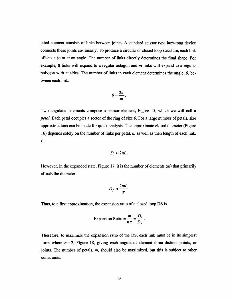
lated element consists of links between joints. A standard scissor type lazy-tong device
connects these joints co-linearly. To produce a circular or closed loop structure, each link
offsets a joint at an angle. The number of links directly determines the final shape. For
example, 8 links will expand to a regular octagon and m links will expand to a regular
polygon with m sides. The number of links in each element determines the angle, 0, be-
tween each link:
2;r9=-
m
Two angulated elements compose a scissor element, Figure 15, which we will call a
petal. Each petal occupies a sector of the ring of size 0. For a large number of petals, size
approximations can be made for quick analysis. The approximate closed diameter (Figure
16) depends solely on the number of links per petal, n, as well as then length of each link,
L:
Di. ; 2nL.
However, in the expanded state, Figure 17, it is the number of elements (m) that primarily
affects the diameter:
2mL
Thus, to a first approximation, the expansion ratio of a closed loop DS is
m D iExpansion Ratio 2Z -n; Df
Therefore, to maximize the expansion ratio of the DS, each link must be in its simplest
form where n = 2, Figure 18, giving each angulated element three distinct points, or
joints. The number of petals, m, should also be maximized, but this is subject to other
constraints.
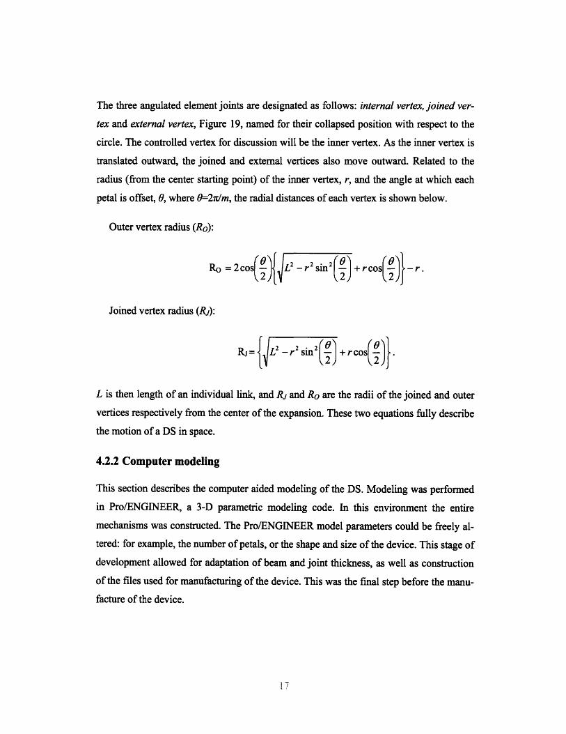
The three angulated element joints are designated as follows: internal vertex, joined ver-
tex and external vertex, Figure 19, named for their collapsed position with respect to the
circle. The controlled vertex for discussion will be the inner vertex. As the inner vertex is
translated outward, the joined and external vertices also move outward. Related to the
radius (from the center starting point) of the inner vertex, r, and the angle at which each
petal is offset, 0, where 0=-2rm, the radial distances of each vertex is shown below.
Outer vertex radius (Ro):
Ro= 2cos L2 -r 2 Sil2I +rco<O) -r.
Joined vertex radius (Rj):
RJ= L2 2 Sinj2 + rcos .
L is then length of an individual link, and Rj and Ro are the radii of the joined and outer
vertices respectively from the center of the expansion. These two equations fully describe
the motion of a DS in space.
4.2.2 Computer modeling
This section describes the computer aided modeling of the DS. Modeling was performed
in Pro/ENGINEER, a 3-D parametric modeling code. In this environment the entire
mechanisms was constructed. The Pro/ENGINEER model parameters could be freely al-
tered: for example, the number of petals, or the shape and size of the device. This stage of
development allowed for adaptation of beam and joint thickness, as well as construction
of the files used for manufacturing of the device. This was the final step before the manu-
facture of the device.

4.3 Kinematics
This section describes the movement and expansion of the DS. The use of parametric
modeling for the linkages provided a significant amount of information both conceptually
and analytically, and the 3-D parametric model confirmed the numerical predictions.
With the device model entirely configurable, manipulation required little effort, and new
shapes and ideas could be visualized rapidly. Further analysis provided a small discovery
regarding the stability near maximum expansion.
4.3.1 Localized stability
A reference for describing the expansion of the structure is required. The two references
will be an inner inscribed circle radius, and an outer circumscribed circle radius as illus-
trated in Figure 20. In a simple DS, there are three distinct expansion states. The first
occurs when the outer shape of the device reaches that of a regular polygon of number m.
Further expansion places the outer shape into a regular polygon, now of number 2m. The
next state occurs when joint members overlap perfectly and form a regular polygon again
with number m. This final state is only theoretical as it assumes zero joint thickness.
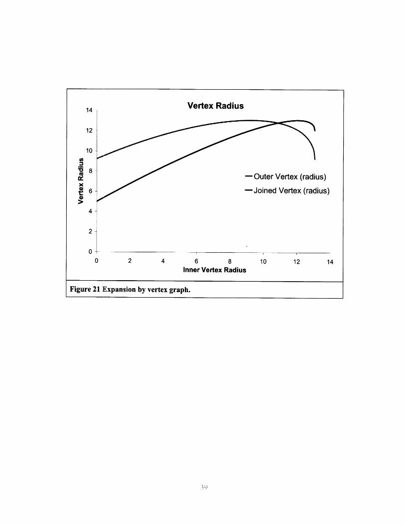
What is important is that, even though the inner diameter is expanded, the outer mecha-
nism is not always expanding. A polygon of number m has a larger average diameter than
a polygon of side 2m. Therefore, a small dip in outer diameter is seen near full expansion,
Figure 21.
It is hypothesized that this dip will provide a source of stability. If the device is expanded
past the first state, and allowed to reach state 2, an external force, if applied correctly,
should not necessarily collapse the structure. This is because to collapse, the external di-
ameter would need to increase marginally before fully collapsing. Therefore a range of
stability is achieved. This prompted the design of the DS to be in state 2 at the desired
expansion.
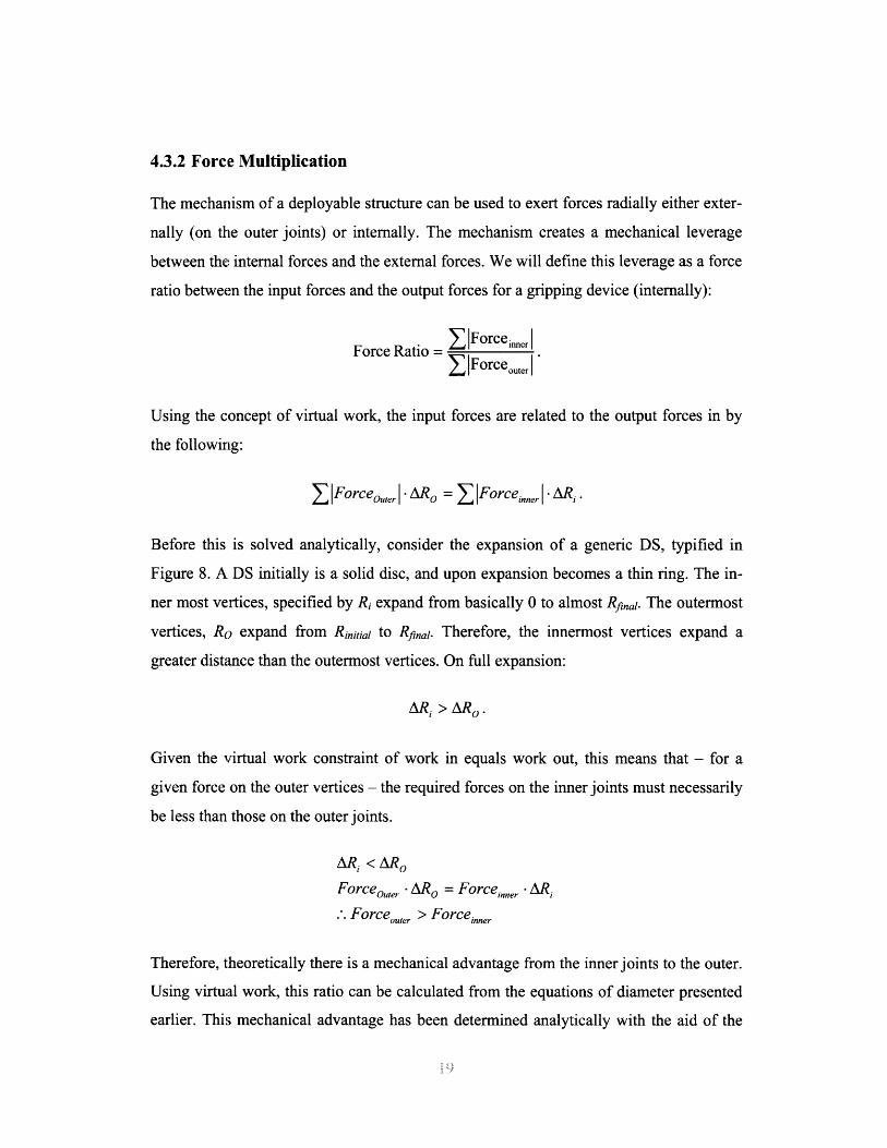
4.3.2 Force Multiplication
The mechanism of a deployable structure can be used to exert forces radially either exter-
nally (on the outer joints) or internally. The mechanism creates a mechanical leverage
between the internal forces and the external forces. We will define this leverage as a force
ratio between the input forces and the output forces for a gripping device (internally):
1 Forceiner IForce Ratio = ForceerSIForceouter
Using the concept of virtual work, the input forces are related to the output forces in by
the following:
ZIForceo,, Ier AR o = IForceinner . ARi.
Before this is solved analytically, consider the expansion of a generic DS, typified in
Figure 8. A DS initially is a solid disc, and upon expansion becomes a thin ring. The in-
ner most vertices, specified by Ri expand from basically 0 to almost Rfinal. The outermost
vertices, Ro expand from Rinitial to Rfinal. Therefore, the innermost vertices expand a
greater distance than the outermost vertices. On full expansion:
AR i > AR o0
Given the virtual work constraint of work in equals work out, this means that - for a
given force on the outer vertices - the required forces on the inner joints must necessarily
be less than those on the outer joints.
ARi < ARo
Forceo,uer A Ro = Forceinner •R i
.'. Forceouter > Forceinner
Therefore, theoretically there is a mechanical advantage from the inner joints to the outer.
Using virtual work, this ratio can be calculated from the equations of diameter presented
earlier. This mechanical advantage has been determined analytically with the aid of the

Matlab computing environment. Using virtual work, it was shown that the force multipli-
cation ratio is always less than 1 when transferring force to the center (i.e. a griping
action) and that the force transmission ratio increases with the size of the device (L), as
shown in Figure 22. This graph illustrates the declining force transmission ratio from ex-
ternal nodes to internal nodes of a DS at high expansion for a DS with 12 links (m=12). L
length corresponds to the length of an angulated element and is therefore correlated to the
size of the device. As the structure approaches its maximum expansion, the force trans-
mission between the inside and the outside drops considerably. Additionally, it should be
noted that the transmission ratio approaches 100% asymptotically as L approaches infin-
ity. The inner diameter ranges from 32 mm to 86 mm corresponding to standard tool
diameters of 1.25 in. to 3 3/8 in.
5. EMBODIMENT DETAILS
5.1 Shape
This section will describe the shape of some prototype embodiments that have been pat-
ented by Schlumberger. In summary, a design was modified to produce a rigid, gap-less
device, Figure 23. The first design iterations considered only straight links as shown in
Figure 24. The next step was to alter the shape to create a truly circular perimeter as op-
posed to a polygon. This was achieved by adding curved sections to each link (Figure
25). Next, thickening the part at strategic locations eliminated wall gaps when the layers
were stacked (Figure 26) to provide a continuous 3-D structure.
5.2 Snap fit
To prevent collapsing and provide strength to the deployed device, a snap fit mechanism
was designed. The snap fit integration provides a useful tool for down-hole applications
where strength and reliability are paramount. As mentioned above, the design of the DS
was inside a stability range that could significantly increase the resistance to collapse.
The shape of the structure of the DS prompted an analogy to an arched bridge. To accen-
tuate the arched bridge concept additions were added to provide a continuous band of
material when fully deployed causing the device to "lock together" when stressed (Figure

27). These additions provided the material for a mechanical locking snap fit mechanism
to further strengthen the device.
Snap fits fall into three basic categories: in-plane motion, out-of-plane motion and annu-
lar (Figure 28). In each of these categories there are two distinct subsets: resistive and
permanent snaps, as shown in Figure 29. A resistive snap is designed to provide a weak
hold, such as those found on cabinet doors, while a permanent snap fit is designed to re-
main in place, such as a remote control plastic assembly cover. The prototype was
designed with an in plane snap to allow for effective stacking of layers. The first proto-
type had only one snap position at full expansion (Figure 30). The next iterations had a
ratchet mechanism to hold the device stiff in several different expansion states (Figure
31). This would provide a greater flexibility in use as the device would remain rigid at
different expansion states.
5.3 Manufacture
Figure 23 shows a layered prototype of the DS. The individual link is shown in Figure 32.
The petal is composed of two links and is the primary component of the device. The
mechanism is entirely constructed from these two-dimensional components. Each layer
consists of 9 petals stacked back to back, but this number can be anything larger than
three. Additional features such as a snap fit or void filling (to achieve a smooth outer sur-
face) are provided by a separate feature rigidly attached to the petal (Figure 31).
The devices shown were cut from /4" aluminum 6061 sheets on a two-axis abrasive wa-
ter-jet system (OMAX). Minimal machining of the part was required after water-jet
cutting. Each petal has five holes, two of which connect the additional void-fill pieces,
and the other three are pivots. These joints were connected with 1/16" threaded rods to
facilitate joining them.
At large expansion ratios, the joint thickness plays and important role, specifically the
inner most pivots. As such, in the prototype shown (Figure 33) the joints were modified
to allow the parts to fit together closely.
6. ACTUATION AND DEPLOYMENT
This section will describe some of the proposed methods of actuating a DS. Deploying a
DS consists of changing the size and shape from a collapsed and reduced shape to an ex-
panded shape. Actuation is required to control the expansion and fully utilize the benefits
of a deployable device. However, actuation of the device is not trivial, specifically be-
cause the only stationary reference point is in the center of the device, which is often
desired to be void.
6.1 Description of actuation systems:
Successful actuation of the generic deployable structure occurs when at least three pivot
points are translated radially from a center. This section describes different methods of
mechanical actuation and their advantages and disadvantages.
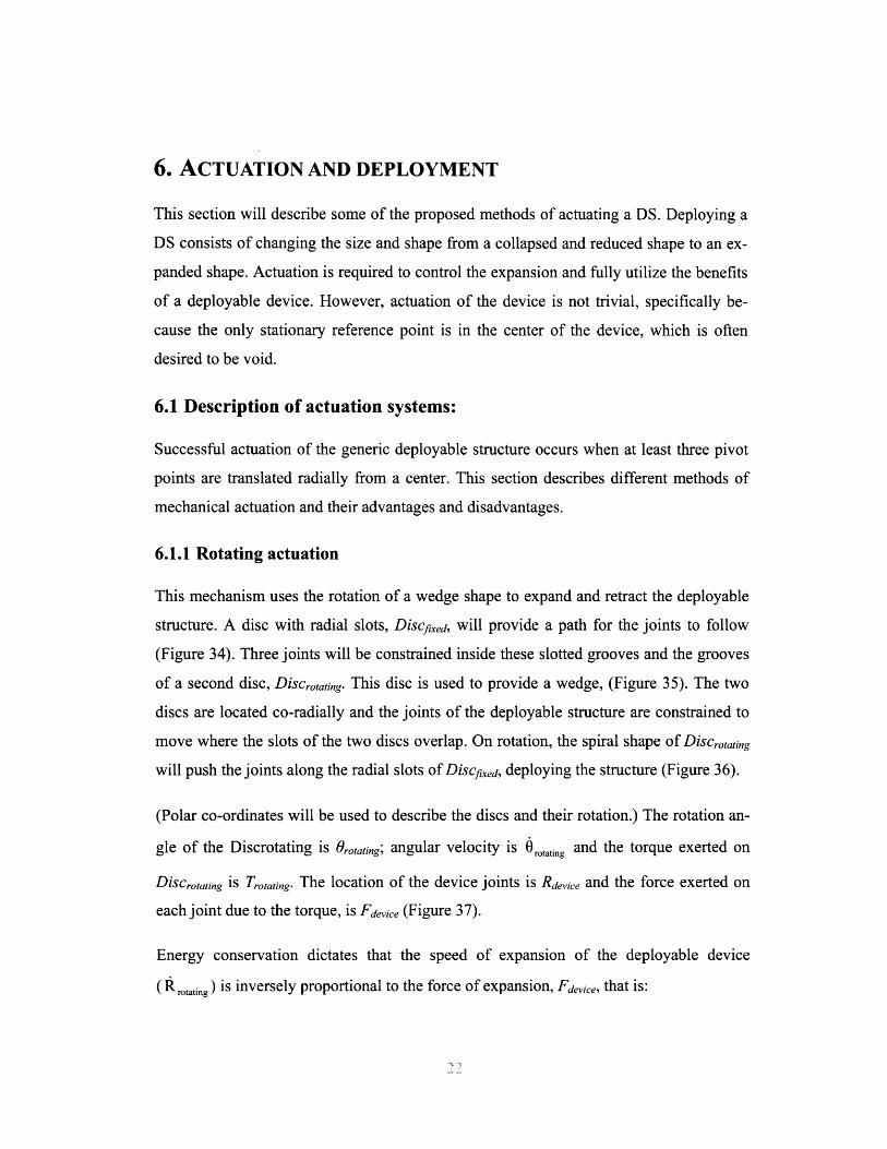
6.1.1 Rotating actuation
This mechanism uses the rotation of a wedge shape to expand and retract the deployable
structure. A disc with radial slots, Discfxed, will provide a path for the joints to follow
(Figure 34). Three joints will be constrained inside these slotted grooves and the grooves
of a second disc, Discrotating. This disc is used to provide a wedge, (Figure 35). The two
discs are located co-radially and the joints of the deployable structure are constrained to
move where the slots of the two discs overlap. On rotation, the spiral shape of Discrotating
will push the joints along the radial slots of Discfxed, deploying the structure (Figure 36).
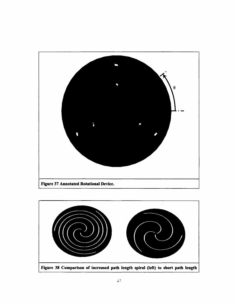
(Polar co-ordinates will be used to describe the discs and their rotation.) The rotation an-
gle of the Discrotating is Oro,atig; angular velocity is orotating and the torque exerted on
Discrotating is Trotating. The location of the device joints is Rdvice and the force exerted on
each joint due to the torque, is Fdevice (Figure 37).
Energy conservation dictates that the speed of expansion of the deployable device
( rotating) is inversely proportional to the force of expansion, Fdeice, that is:

rotating rotating i Fdie
S= Fdevice
The quantity
Trotating
JIFdevicel
is the ratio of the torque exerted on the system to the force exerted on the device. This
ratio is essentially the force multiplication ratio. The force multiplication ratio can be al-
tered by changing the shape of slotted paths on Discrtating. For example, a Disctating with
slotted paths that have a length several times that of the disc's radius will produce a large
expansion force, but will subsequently require multiple rotations of the disc to fully ex-
pand the device (Figure 38). The slotted paths are a function defined in polar co-
ordinates: r = f(0). Note that the derivative of the path radius with respect to 0 gives the
torque multiplication factor:
dr Trotating
dO IFFdevice l
In general, the function of a device determines the desired force multiplication, which can
be suited for different applications. For example, a disc that produces a constant force
multiplication regardless of expansion diameter has the slotted path equation of:
r=a.o
where a is the force multiplication. A constant force multiplication ratio could be used in
applications where a single desired force is at several different radii. Different jobs re-
quire different force multiplication ratios which can be generated by altering the slotted
path shape. Essentially a path for each specific desired force ratio could be created.
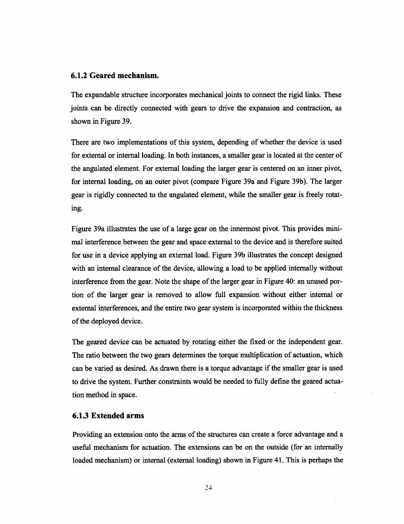
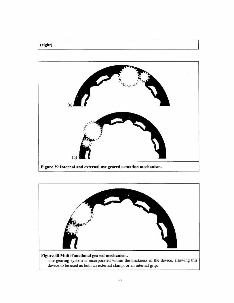
6.1.2 Geared mechanism.
The expandable structure incorporates mechanical joints to connect the rigid links. These
joints can be directly connected with gears to drive the expansion and contraction, as
shown in Figure 39.
There are two implementations of this system, depending of whether the device is used
for external or internal loading. In both instances, a smaller gear is located at the center of
the angulated element. For external loading the larger gear is centered on an inner pivot,
for internal loading, on an outer pivot (compare Figure 39a and Figure 39b). The larger
gear is rigidly connected to the angulated element, while the smaller gear is freely rotat-
ing.
Figure 39a illustrates the use of a large gear on the innermost pivot. This provides mini-
mal interference between the gear and space external to the device and is therefore suited
for use in a device applying an external load. Figure 39b illustrates the concept designed
with an internal clearance of the device, allowing a load to be applied internally without
interference from the gear. Note the shape of the larger gear in Figure 40: an unused por-
tion of the larger gear is removed to allow full expansion without either internal or
external interferences, and the entire two gear system is incorporated within the thickness
of the deployed device.
The geared device can be actuated by rotating either the fixed or the independent gear.
The ratio between the two gears determines the torque multiplication of actuation, which
can be varied as desired. As drawn there is a torque advantage if the smaller gear is used
to drive the system. Further constraints would be needed to fully define the geared actua-
tion method in space.
6.1.3 Extended arms
Providing an extension onto the arms of the structures can create a force advantage and a
useful mechanism for actuation. The extensions can be on the outside (for an internally
loaded mechanism) or internal (external loading) shown in Figure 41. This is perhaps the
simplest method of generating a force multiplication. This solution would again need
constraints to define its position in space.
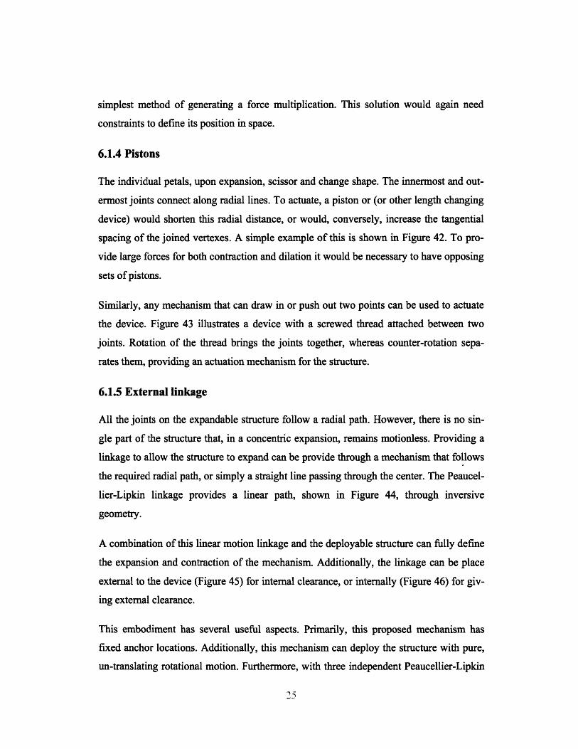
6.1.4 Pistons
The individlual petals, upon expansion, scissor and change shape. The innermost and out-
ermost joints connect along radial lines. To actuate, a piston or (or other length changing
device) would shorten this radial distance, or would, conversely, increase the tangential
spacing of the joined vertexes. A simple example of this is shown in Figure 42. To pro-
vide large forces for both contraction and dilation it would be necessary to have opposing
sets of pistons.
Similarly, any mechanism that can draw in or push out two points can be used to actuate
the device. Figure 43 illustrates a device with a screwed thread attached between two
joints. Rotation of the thread brings the joints together, whereas counter-rotation sepa-
rates them, providing an actuation mechanism for the structure.
6.1.5 External linkage
All the joints on the expandable structure follow a radial path. However, there is no sin-
gle part of the structure that, in a concentric expansion, remains motionless. Providing a
linkage to allow the structure to expand can be provide through a mechanism that follows
the requiredl radial path, or simply a straight line passing through the center. The Peaucel-
lier-Lipkin linkage provides a linear path, shown in Figure 44, through inversive
geometry.
A combination of this linear motion linkage and the deployable structure can fully define
the expansion and contraction of the mechanism. Additionally, the linkage can be place
external to the device (Figure 45) for internal clearance, or internally (Figure 46) for giv-
ing external clearance.
This embodiment has several useful aspects. Primarily, this proposed mechanism has
fixed anchor locations. Additionally, this mechanism can deploy the structure with pure,
un-translating rotational motion. Furthermore, with three independent Peaucellier-Lipkin

linkages, the device is fully constrained to expand concentric to a location. If two link-
ages were connected via gears, then this alone defines the expansion fully and could be a
viable method of deploying the device. Thus, this linkage can be incorporated into all the
previously explored concepts and provide a constraining base for expansion, if not used
by itself for actuation.
6.2 Conclusion of actuation mechanisms
Several patented actuation methods exist for deployable structures, all with very different
functional properties. The environment in which the structure is used and whether the de-
vice is to be used internally or externally will change the actuation method employed, as
well as the desired force multiplication.
7. CONCLUSION
Most deployable structures have not been developed for downhole applications. More
importantly, there is no existing structure developed that utilizes this specific structure to
perform mechanical work. The analysis of expandable mechanisms has shown that cer-
tain deployable structures are valuable as devices to convey material and to exert forces.
Certain deployable structures can be designed to perform mechanical work and can be
optimized for mechanical advantage based on the required loading. We have specified the
mechanical advantage of these structures as a known function of geometry and structure
expansion (Section 4.3.2, Figure 22).
Furthermore, we have described and investigated issues that should be considered in the
design and actuation of deployable structures. The mechanism can be adapted depending
on whether the device is intended for internal or external loading. There is always a force
reduction for deployable structures that receive the action load on the outer perimeter and
exert a load with the inner perimeter. Conversely, an inner located force will be amplified
through the DS externally. Yet in both these cases, the correct choice of actuation system
can control the structure's overall force ratio. A developed understanding of the kinemat-
ics of the deployable structure has been presented in section 4.2.1. Furthermore,
equations axe available to predict the force multiplication over a range of device sizes and
expansion ratios.
8. REFERENCES
[01] Guerrero, Julio C.; Culpepper, Martin L.; Varadarajan, Kartik M.; "Design of Self-
Conforming Compliant Mechanism To Anchor Within Conduits of Various Shapes
and Sizes," 2005 (Schlumberger Research Report OFSR/PR/2005/066/MMS/U).
[02] Guerrero, Julio C.; Munro, Logan; "Actuation mechanisms for deployable struc-
ture," 2007 (Schlumberger Patent Memo, May, 2007)
[03] Pellegrino, S. and You, Z.: "Expandable/Collapsible Structures," International pat-
ent No. WO 97/27369 (1997).
[04] Hoberman, C.: "Reversible expandable structure," European Patent No.
EP0443408B 1 (1991).
[05] Hoberman, C.: "Radial expansion/retraction trust structure," European Patent No.
EP0455850B1 (1990).
[06] Hoberman, C.: "Reversible expandable structures having polygon links" European
Patent No. EP1072295A2 (2000).
[07] Hoberman, C.: "Loop assemblies having a central link" International Patent No.
W02002063111A1 (2002).
[08] Hoberman, C.: "Folding covering panels for expanding structures" International
Patent: No. W02003054318A2 (2003).
[09] Zeigler, T.R.: "Collapsible/expandable structural module with hub locking" Euro-
pean Patent No. EP0118619A1 (1983).

9. APPENDIX A
Appendix relating to shell:
The 4 patents from Shell that are most related to this area of inventions follow:
a) "Method and system for reducing longitudinal fluid flowaround a permeable well", US7059410B2. Assignee: Shell,year 2006. Inventors: Bousche, Olaf Jean Paul; Runia, DouweJohannes. This is an umbrella deployed in the well, it arrangesa series of collapsed resilient sealing rings at regular longitudi-nal intervals around the permeable tubular before lowering thetubular into the well by means of tape and/or a binder whichdissolves downhole. Figure 3 shows details of this invention.
b) "Contractable [sic] and expandable tubular wellbore system",GB2397084A, W02003031771[Al]. Assignee: Shell, year2004. Inventors: Lohbeck, Wilhelmus, and Christianus Maria.This is a ring with notches that allow it to be bent; it does nothave an expansion ratio, because it does not expand, it just un-folds. Figure 4 shows details of this invention.
c) "Foldable tube", EP1073825bl. Assignee; Shell, year 2003.Inventors: Lohbeck Wilhelmus, and Christianus Maria. This isanalogous to the previous one, but with more foldable facets.Figure 5 shows details of this invention.
d) "Expandable wellbore assembly", W02005031115al. As-signee: Shell, year 2006. Inventors: Lohbeck Wilhelmus, andChristianus Maria. This is a stent like expandable screen(Figure 6).

Figure 1 Implemented uses of deployable structures.Left: the infamous "Hoberman Sphere" toy. Right: architectural design for an "EXPO2000" work. (photos: hoberman.com)
Figure 2 "Expandable/collapsible Structures-A" patentPatent WO01997027369(A1), 1997, by Sergio Pellegrino.
rPi~sa~ I

U.S. Patent Jun. 13, 2006 Shee I of2
Fig.2.
Figure 3 "Method and system for reducing longitudinal fluid flow around a perme-able well," Shell patent
US patent 7059410B2. Assignee: Shell, year 2006. Inventors: Bousche, Olaf JeanPaul; Runia, Douwe Johannes.
!._ Ar
Figure 4 "Contractable [sic] and expandable tubular wellbore system," Shell patentPatent GB2397084A, W02003031771[A1]. Assignee: Shell, year 2004. Inventors:Lohbeck, Wilhelmus, and Christianus Maria.
US 7,059,410 B2
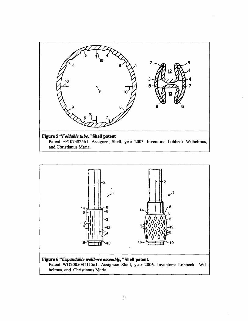
Figure 5 "Foldable tube," Shell patentPatent EP1073825bl. Assignee; Shell, year 2003. Inventors: Lohbeck Wilhelmus,and Christianus Maria.
.1
Figure 6 "Expandable wellbore assembly," Shell patent.Patent WO02005031115al. Assignee: Shell, year 2006. Inventors: Lohbeck Wil-helmus, and Christianus Maria.
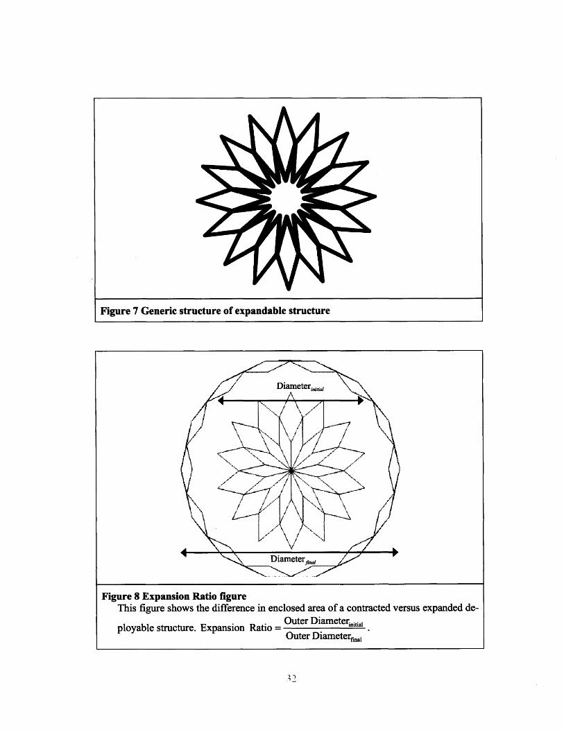
Figure 7 Generic structure of expandable structure
Figure 8 Expansion Ratio figureThis figure shows the difference in enclosed area of a contracted versus expanded de-
Outer Diameterinitialployable structure. Expansion Ratio =
Outer Diameterinal

Figure 9 Deployable structure under actuation and opposing forcesSForce
Force Multiplication Ratio = uter
SForceinne
/1
(a) Closed scissor mechanism (b) Expanded scissor mechanism
Figure 10 Scissor mechanism example; lazy tongs.
axis
Figure 12 Cylindrical Co-ordinates
Noa how legs ge unthe apartas sassor coracts
Figure 11 Schematic showing scissor linkage
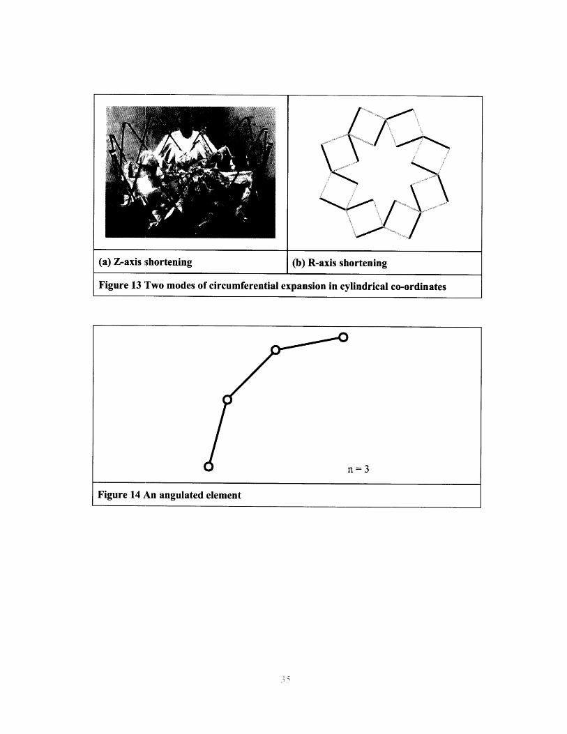
Figure 14 An angulated element
I
(a) Z-axis shortening
Figure 13 Two modes of circumferential expansion in cylindrical co-ordinates
n=3
(b) R-axis shortening
1i
""··-,
-- =

Figure 15 A single petal connected at one joint.
n=3
Di ; 2nL
n =3, m= 14
Figure 16 Simplified equation of diameter for a contracted deployable structure

2mLDf
Figure 17 Simplified equation of diameter for an expanded deployable structure
n=2
Figure 18 Simplest angulated element where n = 2
J
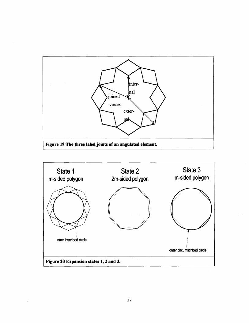
Figure 19 The three label joints of an angulated element.
State 1m-sided polygon
State 22m-sided polygon
State 3m-sided polygon
inner inscribed circle
outer circumscribed circle
Figure 20 Expansion states 1, 2 and 3.
Vertex Radius
us)lius)
0 2 4 6 8 10 12 14Inner Vertex Radius
Figure 21 Expansion by vertex graph.
14
12
10
x) 6
4
2
0

- - - -- - . I- -
86-
84--
82-
S80--.E
I--e 78-
76
--H
300250
200.- . .- - -150
30 40 50 60- 70 80 90 100
L length (mm)Inner Diameter (2Ri) (mm)
Figure 22 Graph of force transmission ratio as a function of inner diameter and de-vice size.

Figure 23 Layered, gapless Prototype
Figure 24 Straight link DS iteration
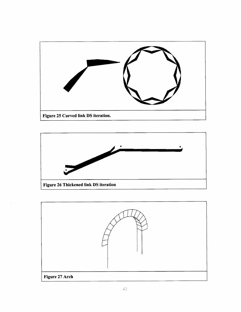
Figure 25 Curved link DS iteration.
Figure 27 Arch
Figure 26 Thickened link DS iteration
I I

From: Bonenberger, Paul R. First Snap-Fit Handbook - Creating Attachments for PlasticParts. (pp. 91). Hanser Publishers. Online version available at: http://tinyurl.com/2x5qon
Figure 28 Various snap fit types.
Figure 29 Releasing and non-releasing snap fits.
~c~ii
Figure 2.16 Non-permanent locksBonenberger, Paul R. First Snap-Fit Handbook - Creating Attachments for Plastic Parts.
(pp. 29). Hanser Publishers. Online version available at: http://tinyurl.com/2x5qon
-c-~

Figure 30 Single snap fit
Figure 31 Ratchet snap
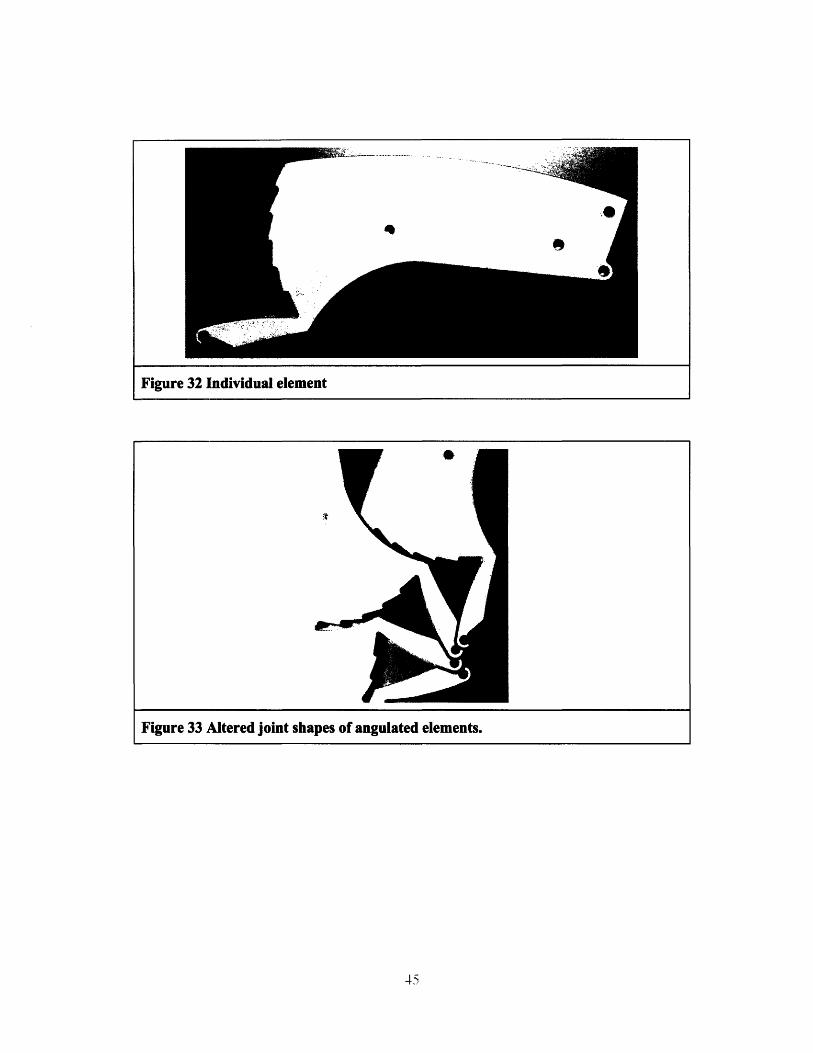
Figure 32 Individual element
Figure 33 Altered joint shapes of angulated elements.

Figure 35 Schematic of Discrotation.
The equation for the path here is: r = 0.5 +10 ( )3"
Figure 36 Time-lapse of rotating spiral disc on stationary disc.
0
Figure 37 Annotated Rotational Device.
Figure 38 Comparison of increased path length spiral (left) to short path length
(right)
(a)
Figure 39 Internal and external use geared actuation mechanism.
Figure 40 Multi-functional geared mechanism.The gearing system is incorporated within the thickness of the device, allowing thisdevice to be used as both an external clamp, or an internal grip.
"I,
KhiJS
j"PT

Figure 41 Schematics of internal and external extended arms device acutation.
Figure 42 Detail of a piston-actuated deployment method.
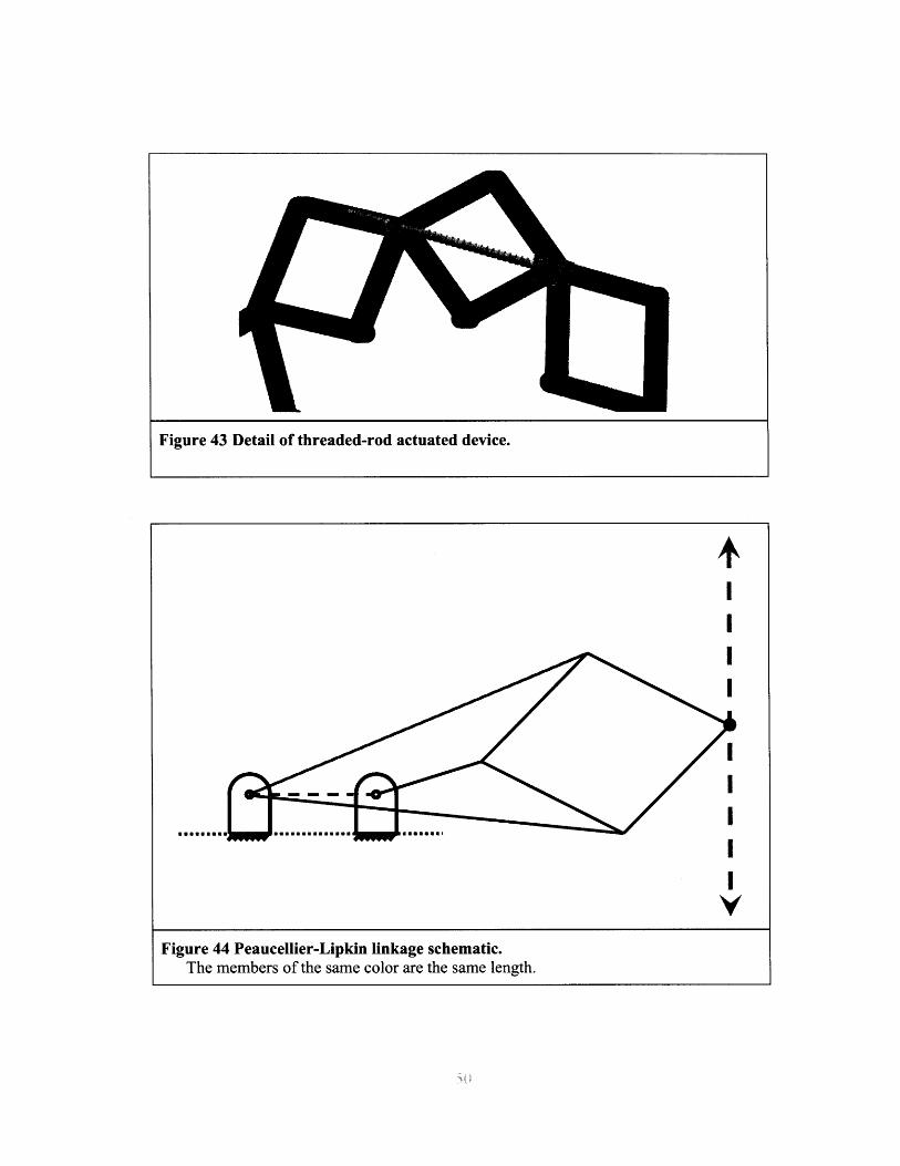
Figure 43 Detail of threaded-rod actuated device.
I
Figure 44 Peaucellier-Lipkin linkage schematic.The members of the same color are the same length.
musenews
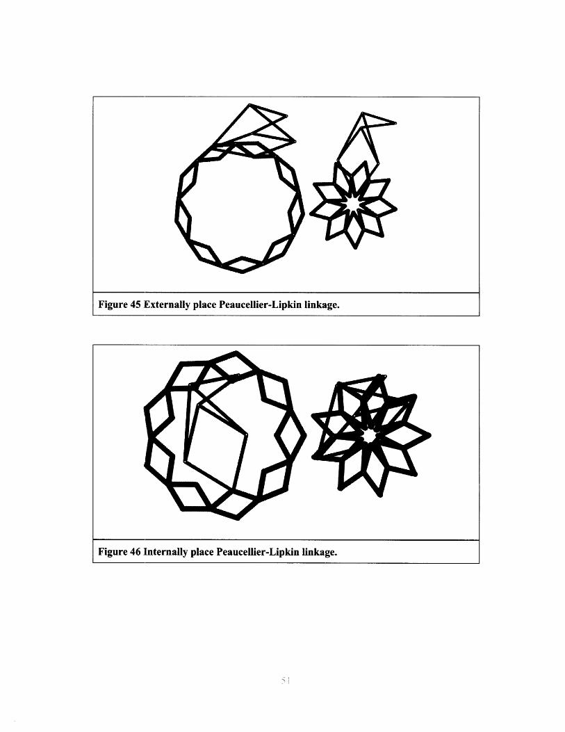
Figure 45 Externally place Peaucellier-Lipkin linkage.
Figure 46 ]Internally place Peaucellier-Lipkin linkage.