investigation of performance analysis of...
TRANSCRIPT

ISSN: 2278 – 7798
International Journal of Science, Engineering and Technology Research (IJSETR)
Volume 2, Issue 4, April 2013
865 All Rights Reserved © 2013 IJSETR
INVESTIGATION OF PERFORMANCE ANALYSIS OF PV FED
MULTILEVEL INVERTER FOR WATER PUMPING
APPLICATIONS
Dr.H.Habeebullah Sait1 S.Arunkumar
2 S.Jayaganesh
2 M.Kesavamoorthi
2 C.Rajagopal
2
Assistant Professor1 , UG Student
2 , Department of EEE, Anna University, BIT Campus,
Tiruchirappalli-620 024.
ABSTRACT:
Inthis paper, the proposed work is to extract
maximum power from the PV powered water
pumping system driven induction motor. The PV
powered water pumping is commonly used for
agriculture and households applications. To seek out
the peak power from the PV array, the inverter is
operated at variable frequency, to vary the output of
the water pump. The proposed system utilizes the
multilevel inverter to generate a sinusoidal waveform
instead of quasi square wave inverter. The
anticipated system has the benefits of less Total
Harmonic Distortion in the output voltage, low
switching losses, less in filter requirements, low
heating of motor under rating condition, less in
ripple torque production and so on. The fuzzy logic
based peak power point tracking technique is
employed. The extraction of peak power is achieved
by varying the frequency of multilevel inverter in
order to operate theinduction motor at maximum
torque condition. The additional features of the PV
fed system is that, the motor current is limited to an
upper limit of PV array current, so that motor
winding and power semi conducting switches can be
protected against excessive current flow. The
system is tested using MATLAB/
simulinkforenvironmentunder different condition like,
change in insolation and change in temperature for
the validation of the proposed work.
I. INTRODUCTION
The Application of PV system has become
popular especially in remote areas, where power is
not available or too costly. The PV powered water
pumping system is frequently used for agriculture
and in households. There are different methods
proposed for extracting maximum power from the PV
array. Maximum Power Point(MPP) may vary time to
time due to different levels of insolation. For water
pumping system induction motor optimization is
obtained by v-f relation of motor [1]. Different
pumps are available for water pumping, among those
centrifugal pumps are mostly used. The optimum
utilization achieved by proper load matching is the
simple technique [2]. The output of PV array is dc
which have to be converted to ac source to drive the
motor pump. For that a six step quasi square wave
inverter is proposed to run the motor by tracking the
maximum power using variation in inverter
frequency to reduce the switching losses [3]. MPP
can alsotrack by using the duty ratio of converter in
case of using a battery forcharging the PV output
power, which is generally placed between PV&
battery. Optimization of PV pumping system can also
done based on new reference voltage criterion which
is the addition of open circuit voltage of PV and a
segment of solar radiation so as to ensure the
optimum chopping ratio of a back boost converter
[4]. Three MPPT are used for this operating
conditions (i) with variable voltage and current (ii)

ISSN: 2278 – 7798
International Journal of Science, Engineering and Technology Research (IJSETR)
Volume 2, Issue 4, April 2013
866 All Rights Reserved © 2013 IJSETR
with fixed voltage and varying current (iii) with
variable reference voltage based on fixed percentage
of open circuit voltage. Efficient usage of PV array is
done by spraying water over PV panels which
reduces the degradation of PV [5]. Sensor less
BLDC motor can also be used instead of IM where
MPP tracked by controlling Z-source inverter [6].
Perturb and observe algorithm for MPPT is used for
good efficiency without a battery[7].
The system proposed and analysed in this
paper is PV fed water pumping system without a
battery, utilizing the diode clamped five level inverter
instead of six step quasi square wave inverter in order
to reduce the Total Harmonic Distortion (THD). Here
the MPP is tracked by varying operating frequency of
the Induction motor utilizing the multilevel dc-ac
inverter, with that maximum power of the PV array
the motor pumps the water. The inverter is modulated
to adjust the frequency of the induction motor to
search for the optimum power of PV array.
Fig.1 block diagram of proposed system
The block diagram of the system is shown in Fig. 1.
The PV array receives energy from the sunlight. The
PV array generates electric power, which is fed to the
induction motor via an inverter. The induction motor
is mechanically coupled to the water pump. As the
insolation level varies during the day, the output of
the PV array follows the change. The water pump is a
centrifugal pump, with the output torque varying as
the square of its rotor speed. To increase the output of
the water pump, the speed of the water pump is
increased by adjusting the frequency of the inverter.
II. PV ARRAY MODEL
The optimum power of the PV is useful for
any purposes. But the power output of the PV varies
instantly due to the various level of insolation. The
overall output of PV depends on the number of cells
presented in the array, the total power has the
contribution of each cell. So, by calculating the
output of one cell, we may calculate the total output
easily. The Fig .2 shows the equivalent circuit of a
PV cell.
Fig .2, equivalent circuit of a PV cell
The nonlinear Ipv - Vpv and Ppv - Vpv
characteristics of solar cells are well known. Using
equivalent circuit of Fig.2, the nonlinear Vpv - Ipv
characteristics of PV module is:
𝑽𝒑𝒗 =𝟏
𝛌𝐥𝐧(
𝑰𝒔𝒄 − 𝑰𝒑𝒗 + 𝑰𝟎
𝑰𝟎) − 𝑹𝒔𝑰𝒑𝒗(𝟏)
Where Iscis the cell short-circuit current, Io is the
reverse saturation current, Rsis the series cell
resistance, and λ is a constant coefficient and depends
upon the cell material. Equation (1) expresses a
nonlinear relation between voltage current
characteristic of a PV module.
The PV array is formed by the combination
of many PV cells connected in series and parallel
fashion to provide the desired value of output voltage
and current. This PV array exhibits a nonlinear
insolation- dependent V-I characteristic,
mathematically expressed consisting of Ns cells in
series and Np cells in parallel as

ISSN: 2278 – 7798
International Journal of Science, Engineering and Technology Research (IJSETR)
Volume 2, Issue 4, April 2013
867 All Rights Reserved © 2013 IJSETR
𝑽𝑨 = −𝑰𝑨 𝑵𝒔
𝑵𝒑
+ 𝑵𝒔
𝐥𝐧 𝟏
+𝑵𝒑𝑰𝒑𝒉 − 𝑰𝑨
𝑵𝒑𝑰𝟎 𝟐
= (q/AKT),q is the electric charge; A is the
completion factor; K is the boltzmann’s constant; T is
the absolute temperature; Rs is the cell series
resistance; Iph is the photo current; Io is the cell
reverse saturation current; IA and VA are solar cell
array current and voltage. The characteristic curves of
PV is shown in following fig
Fig .3.1 I-V characteristic of PV array
Fig .3.2 P-V characteristic of PV array
III. MULTI LEVEL INVERTER
The Multilevel Voltage Source Inverter is
recently applied in many industrial applications as
AC power supplies, static VAR compensators, drive
systems, etc… The significant advantage of
multilevel configuration is the harmonic reduction in
the output waveform without increasing switching
frequency or decreasing the inverter power output. As
the number of levels reach infinity, the output THD
approaches zero.
There are three types of multilevel inverter in usage,
they are (1) Diode Clamped Inverters
(2) Flying capacitors Inverters (3) cascaded Inverters
Among these types Diode clamped inverters are used
for this investigation.
Diode clamped inverters
An m-level diode clamped inverter typically
consists of (m-1) capacitors on the dc bus and
produces m levels of phase voltages. An m-level
inverters leg requires (m-1) capacitors, 2(m-1)
switching devices and (m-1)(m-2) clamping diodes.
SWITCHING STATES :
Va0 Sa1 Sa2 Sa3 Sa4 Sa5 Sa6 Sa7 Sa8
Vdc ON ON ON ON OFF OFF OFF OFF
3Vdc/4 OFF ON ON ON ON OFF OFF OFF
Vdc/2 OFF OFF ON ON ON ON OFF OFF
Vdc/4 OFF OFF OFF ON ON ON ON OFF
0 OFF OFF OFF OFF ON ON ON ON
These switching states is for the five level
diode clamped inverter. Based on these switching
states the switches should be operate to generate a
stepped sinusoidal voltage waveform of desired
output. The circuit diagram and thewaveform for this
inverter is shown Fig.4.1 &4.2
Fig .4.1 five level diode clamped inverter

ISSN: 2278 – 7798
International Journal of Science, Engineering and Technology Research (IJSETR)
Volume 2, Issue 4, April 2013
868 All Rights Reserved © 2013 IJSETR
Fig.4.2 load voltage waveform of five level diode clamped inverter
IV. MOTOR AND PUMP
CHARACTERISTICS
To optimize the energy captured, the PV
array should always operate at its maximum output
power as the insolation changes. The output power of
the motor can be varied by changing the speed of the
water pump. The speed of the water pump is
regulated by controlling the inverter frequency. Thus
inverter is the interface between the PV array and the
electric motor. For the electric motor, a water pump
is needed for this application. Mostly water pump
chosen is the centrifugal pump where the output is
propotional to the cube of the rotor speed. The output
power and torque can be written as
𝐏 = 𝑲𝒘𝑾𝒎𝟑 (𝟑)
𝑻 = 𝑲𝒘𝑾𝒎𝟐 (𝟒)
where, Kw, is the consant of water pump in
watts/(mech rad/s)3 andWm is the rotor speed in mech
rad/s
Thus, to vary the output of the water pump,
the frequency supply of the electric motor driving the
pump must be varied. The operation of the inverter
and electric motor is related to the characteristics of
the PV array. The PV array, as can be seen from Fig.
3.1&3.2, behaves approximately as a current source
when the voltage output of the PV array is lower than
the optimum voltage, and it behaves as a voltage
source when the output voltage of the PV array is
higher than the optimum voltage. As the slip of the
motor is varied, the resistance of the variable resistor
follows the change accordingly. The slip is adjusted
indirectly, by controlling the frequency of the
inverter. Thus, at any speed slip can be changed from
unity to zero, or even to a negative value, by
changing the frequency applied to the induction
motor.
TheFuzzy Knowledge Base rule associates
the fuzzy output to the fuzzy inputs is derived by
understanding the system behavior. In this paper, the
fuzzy rules are designed to incorporate
Fig.5, Equivalent circuit of induction motor

ISSN: 2278 – 7798
International Journal of Science, Engineering and Technology Research (IJSETR)
Volume 2, Issue 4, April 2013
869 All Rights Reserved © 2013 IJSETR
Fig .6.1, speed-torque characteristics of IM voltage source and
current source
Fig.6.2, Connected to PV inverter for different frequencies
The torque-speed characteristics of the
induction motor connected to the voltage source
differ from the characteristics of the induction motor
connected to a current source. The slip frequency
where the peak torque occurs can be computed. For a
voltage source& a current source, the slip frequency
is,
sωe-peak≈R'r
(Rs
ωe)2
+(L1s
+L'1r)2
(𝟓)
𝒔𝝎𝒆−𝒑𝒆𝒂𝒌 ≈𝑹′
𝒓
𝑳′𝒎 + 𝑳′ 𝟏𝒓 (𝟔)
The behavior of the system depends on the
operating voltage of the PV array. In the low slip
region, the impedance of the system is high. For the
same amount of current, the terminal voltage is
higher in the low-slip region than in a high-slip
region; thus, the PV inverter operates as a voltage
source. As the slip increases, the terminal voltage of
the induction motor is lower, so it tends to behave as
if in a more current-source mode. Near the optimum
voltage, the torque-speed condition of the induction
motor connected to a PV inverter is between the
current-source and voltage source modes, as
illustrated by the torque-speed (dashed) line shown in
Fig. 6.1. The operation of the system is related to the
range of slip between peak slip and zero slip. To
compute the approximate optimum frequency, the
following assumptions should be made.
1) The optimum voltage of the PV array is constant.
2) The mechanical output power of the water pump is
approximately proportional to the cube of the
frequency.
3) There are no mechanical and electrical losses in
the conversion process.
The mechanical output power of the water pump and
the output power of the PV array are equal if the
losses in the motor and the power converter are
neglected. They can be written as
𝑷 = 𝑲𝒇𝟑 = 𝑽𝒅𝒄−𝒐𝒑𝒕𝑰𝒔𝒄−𝒄𝒆𝒍𝒍 (𝟕)
Vdc-opt is the average optimum voltage of PV array
(known)
Isc-cell is the current of the PV array at low voltage or
short circuit for normal conditions(measured)
V. MPPT ALGORITHMUSING FUZZY
CONTROLLER
To extract the maximum power from the PV
array MPPT algorithm is used. Here fuzzy logic is
proposed for tracking the maximum power from the
PV array. By using the incremental conductance
method of MPPT we are seeking out the MPP with

ISSN: 2278 – 7798
International Journal of Science, Engineering and Technology Research (IJSETR)
Volume 2, Issue 4, April 2013
870 All Rights Reserved © 2013 IJSETR
the conductance value at every instant of varying
insolation. Based on the pre conductance and present
conductance value the change in conductance value is
observed. From that value, we track the MPP. This
job is done by varying the inverter frequency. The
flow chart for the incremental conductance algorithm
is shown below. Based on this flow chart, the
algorithm is proposed to find the MPP to drve the
Induction motor for water pumping applications. For
this algorithm we use fuzzy logic control for the
objective.
Fig .7, MPPT flow chart
In recent years, FLCs have been widely used
for industrial processes owing to their heuristic nature
associated with simplicity and effectiveness for both
linear and nonlinear systems. Advantages of fuzzy
logic controllers over the conventional controllers
are: 1) they do not need accurate mathematical
model; 2) they can work with imprecise inputs; 3)
they can handle nonlinearity; 4) they are more robust
than conventional nonlinear controllers. This section
will briefly describe the techniques used in fuzzy
logic controller, viz., fuzzification, fuzzy knowledge
base and defuzzification.
In the fuzzification process the numerical
variable is converted into a linguistic variable. The
following five fuzzy levels are chosen for the
controlling inputs of the fuzzy controller:NBNegative
big, NS Negative small, ZE zero, PS positive small,
PB positive big.
Membership functions for controller inputs,
i.e. 𝐸,𝛥𝐸 and incremental change in the controller
output (𝛥𝑈) are defined on the common normalized
range of[ -1,1].
RULE BASE TABLE FOR FUZZY
CONTROLLER
TheFuzzy Knowledge Base rule associates
the fuzzy output to the fuzzy inputs is derived by
understanding the system behavior. In this paper, the
fuzzy rules are designed to incorporate
the following considerations keeping in view the
overall tracking performance. 1) When the SCA
terminal voltage is much greater than the MP point
voltage (Vm), then change the frequency of the
inverter so as to bring the terminal voltage to Vm. 2)
When the SCA terminal voltage is less than the MP
point voltage, then the change of frequency is
negative and it must be large so as to bring the
terminal voltage to Vm. 3) When the array voltage is
E 𝛥𝐸
NB NS ZE PS PB
NB NB NS NS NS ZE
NS NS NS NS ZE PS
ZE NS NS ZE PS PS
PS PS ZE PS PS PS
PB ZE PS PS PS PB

ISSN: 2278 – 7798
International Journal of Science, Engineering and Technology Research (IJSETR)
Volume 2, Issue 4, April 2013
871 All Rights Reserved © 2013 IJSETR
close to the Vm, then the incremental frequency is
small. 4) When the array voltage is near to MP point
voltage and is approaching it rapidly, then the change
of frequency should be zero so as to prevent
operating point deviation away from the MP point. 5)
When the array voltage is equal to the MP point
voltage, then the change of frequency should be
maintained at zero.
Taking the above points into consideration the fuzzy
rules are derived and the corresponding rule base is
given in Table. These rules can be employed in any
PV system for MP point tracking irrespective of size
and type of converter used.
In the defuzzification process the crisp value of the
change of duty cycle is obtained. This paper uses the
well-known center of gravity method for
defuzzification.
VI. INVESTIGATION OF SIMULATION
RESULTS
This paper mainly investigate about the
usage of multilevel inverter for operating the
induction motor for water pumping application. The
source for the inverter is the solar insolation which is
converted into a dc source by means of the PV panel.
Due to the range of insolation and the number of cells
present in the PV array the output differs time to time
which we seen in the fig .2. For this condition
MPPTalgorithm is used to operate the PV at optimum
condition where the optimum power for each
insolation level is obtained. The Simulink model of
PV reveals the actual condition of this source.
Fig .8 PV model for various insolation
Here the various insolation level is
represented by the repeating sequence stair1 which
gives both high and low values of insolation. For that
the PV has to operate, and V_PV & I_PV are the
outputs of this model. Where, I_PV decreases from
the short circuit value and the V_PV increases to
open circuit voltage. The sub system of this model
and the output of this model are shown below in Fig
.8.1 & 8.2
.
Fig .8.1 subsystem block of PV model
ISSN: 2278 – 7798
International Journal of Science, Engineering and Technology Research (IJSETR)
Volume 2, Issue 4, April 2013
872 All Rights Reserved © 2013 IJSETR
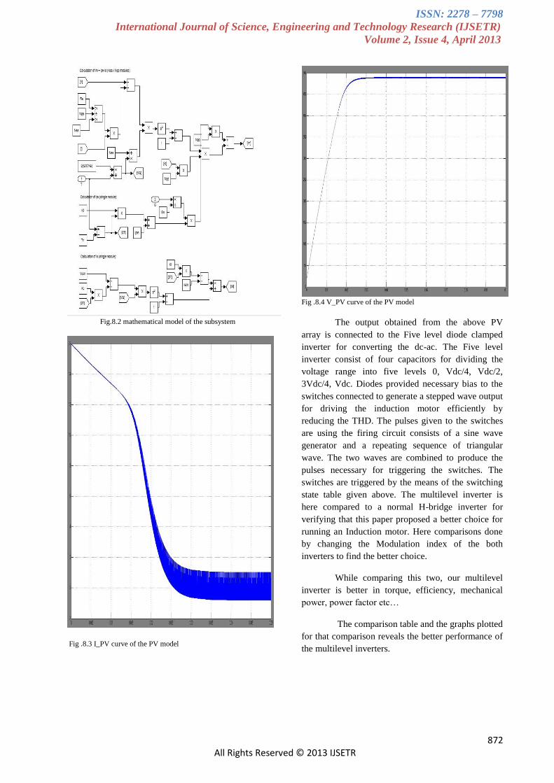
Fig.8.2 mathematical model of the subsystem
Fig .8.3 I_PV curve of the PV model
Fig .8.4 V_PV curve of the PV model
The output obtained from the above PV
array is connected to the Five level diode clamped
inverter for converting the dc-ac. The Five level
inverter consist of four capacitors for dividing the
voltage range into five levels 0, Vdc/4, Vdc/2,
3Vdc/4, Vdc. Diodes provided necessary bias to the
switches connected to generate a stepped wave output
for driving the induction motor efficiently by
reducing the THD. The pulses given to the switches
are using the firing circuit consists of a sine wave
generator and a repeating sequence of triangular
wave. The two waves are combined to produce the
pulses necessary for triggering the switches. The
switches are triggered by the means of the switching
state table given above. The multilevel inverter is
here compared to a normal H-bridge inverter for
verifying that this paper proposed a better choice for
running an Induction motor. Here comparisons done
by changing the Modulation index of the both
inverters to find the better choice.
While comparing this two, our multilevel
inverter is better in torque, efficiency, mechanical
power, power factor etc…
The comparison table and the graphs plotted
for that comparison reveals the better performance of
the multilevel inverters.

ISSN: 2278 – 7798
International Journal of Science, Engineering and Technology Research (IJSETR)
Volume 2, Issue 4, April 2013
873 All Rights Reserved © 2013 IJSETR
Fig .9 Comparison Tabulation between H-bridge and multilevel inverter
Fig .9.1 graph between modulation index Vs power factor
Fig 9.2 graph between modulation index Vs mechanical power
Fig 9.3 graph between modulation index Vs speed
Fig 9.4 graph between modulation index Vs efficiency
PWM BASED MLI FED CAPACITOR START RUN IM IGBT BASED PWM INVERTER FED CAPACITOR
START RUN IM
MI Pmec P.F Eff Speed Torque Pmec P.F Eff Speed Torq
ue
0.4 783 0.82 69.63 148.9 5.259 257.6 0.58 53.4 150.3 1.714
0.5 835.5 0.697 57.17 152.3 5.485 111.7 0.163 17 156.6 0.713
0.7 790.2 0.684 46.78 152.5 5.187 190.1 0.139 15.14 157.2 1.209
0.8 764.4 0.67 51.33 152.7 5 244.9 0.136 14.92 157.5 1.555
0.9 865.3 0.633 54.3 153.6 4.96 307.7 0.135 14.8 157.8 1.95

ISSN: 2278 – 7798
International Journal of Science, Engineering and Technology Research (IJSETR)
Volume 2, Issue 4, April 2013
874 All Rights Reserved © 2013 IJSETR
The simulation diagram and the
corresponding output obtained are given below. The
PV input is given to the multilevel inverter, the
output of which is given to the capacitor start run
motor for settling the motor quickly. The
characteristic curves of the motor is shown in Fig
.10.3, the main and auxillary winding current of the
motor goes on decreasing after the settling time, the
ripple torque is also less providing maximum
efficiency by lowering the hormonics and reduces
the filter components. The same procedure when
used for H-bridge inverter all the effects are
considerably less than the multilevel inverter. We
can observe this difference in the Fig .9-9.4.
Fig .10.1 simulation diagram of H-bridge inverter
Fig .10.2 simulation diagram of multilevel inverter
(a) (b)
Fig .10.3 simulated output characteristics of (a) H-bridge (b)
multilevel inverters
The MPPT block is the final and closed
path of this paper. It is obtained by the fuzzy logic
controller which deals with the incremental
conductance algorithm shown in Fig .7. based on
this algorithm controller stores the present and the
previous conductance value at each instant. If the
conductance value increases means the controller
shifts its position to the new value in order to track
the peak power. In this paper, the V_PV and I_PV
are obtained and its previous value is stored in the
controller, the dI/dV ratio gives the change in
conductance at the present instant. Based on the
dI/dV value the operating frequency of the IM varies
in order to track the optimum power from the PV
array. The MPPT simulation block & controller
block are shown in Fig .11.1-11.3.
Fig .11.1 simulation block of MPPT

ISSN: 2278 – 7798
International Journal of Science, Engineering and Technology Research (IJSETR)
Volume 2, Issue 4, April 2013
875 All Rights Reserved © 2013 IJSETR
Fig .11.2 Subsystem block of MPPT
Fig .11.3 Controller block of MPPT
Fig 11.4 PV Voltage waveform of change in insolation
Fig 11.5 PV current waveform of change in insolation
VII. CONCLUSION
From the investigation of H-bridge and
multilevel inverter we conclude that the multilevel
inverter is the better choice for PV fed water
pumping application. By using the multilevel
inverter as the variable frequency source and the
peak power tracker, the total hormonics distortion,
swithing losses, filter requirements, ripple torque are
minimized, therefore heating of the motor at rated
condition is also reduced. The system is coupled
with a centrifugal water pump, and the controller is
set to adapt to changing insolation and temperature
due to the atmospheric conditions. Using the PV
array has an advantage that, the motor current is
limited to an upper limit of PV array current, so that
no chance of degradation of motor windings due to
short circuit current of PV array.
REFERENCES
1. 1987, S.R.Bhat, and Re Pittet and B.S.Sonde “Performance
optimization of induction motor pump system using
PV energy source ” IEEE Industrial applications, Vol 1a-23 no.6.
2. 1994, NewayArgaw “ Optimization of PV water
pumps coupled with an interfacing pulse width modulated dc/ac inverter power conditioning
device” IEEE Industrial electronics, CH3365-
4/94/0000-1165. 3. 1997, Eduard Muljadi “PV water pumping with a peak
power tracker using a simple six-step square wave
inverter” IEEE Industrial applications, Vol-33 no.3. 4. 2003, MummadiVeerachary, TomonobuSenjyu and
Katsumi Uezato “Neural Network based MPPT of
coupled inductor Interleaved boost converter supplied

ISSN: 2278 – 7798
International Journal of Science, Engineering and Technology Research (IJSETR)
Volume 2, Issue 4, April 2013
876 All Rights Reserved © 2013 IJSETR
PV system using Fuzzy controller” IEEE industrial
electronics,Vol- 5 no.04.
5. 2006, Saadi and Moussi “Optimisation of chopping ratio of back-boost converter by MPPT technique
with a variable reference voltage applied to the
photovoltaic water pumping system” IEEE Industrial electronics,1-4244-0497-5/06.
6. 2009, M. Abdolzadeh and M. Ameri “Improving the
effectiveness of a photovoltaic water pumping system by spraying water over the front of photovoltaic cells“
IEEE Power electronics, 978-1-4244-5971-1/10.
7. 2010,S.A.K.H.MozafariNiapoor, S. Danyali and M.B.B. Sharifian “PV power system based mppt z-
source inverter to supply a sensorlessbldc motor”
IEEE 978-1-4673-0136-7/11.
8. 2011, S.G. Malla, C.N. Bhende and S. Mishra “Photovoltaic based water pumping system” IEEE
Conference paper,ISBN: 978-81-909042-2-3.