io-link system description - pepperl+fuchs
TRANSCRIPT

IO-Link System Description
Technology and Application
Purpose of the documentation
This system description provides an overview for the IO-Link IO technology It presents the interaction of the various components of an IO-Link system and serves to increase the general understanding of IO-Link
Target audience of the system description
This system description is aimed at the following individuals involved with automation systems
Mechanical and plant engineers System integrators Plant owners Non-automation specialists e g design engineers
Additional information about IO-Link can be found on wwwio-linkcom
Preface
IO-Link is the first IO technology for communicating with sensors and actuators to be adopted as an international standard (IEC 61131-9) The goal of the IO-Link Community is to develop and market IO-Link technology
2
Contents
1 Benefits of IO-Link 4
2 System overview 5
21 Overview of IO-Link 5
22 IO-Link interface 6
23 IO-Link protocol 7
24 Device profiles 9
25 IODD and engineering 10
26 Differences of IO-Link Specifications V10 and V11 11
3 Integration into the automation system 12
31 Configuration of the IO-Link system 12
32 Data access from the automation system and HMI device 16
33 Changing and backing up device settings during plant operation 16
34 Replacement of a device or master during operation 17
4 Glossary 18
1 Benefits of IO-Link
The IO-Link system offers decisive advantages as a digital interface for connecting sensors actuators
Open standard according to IEC 61131-9 Devices can be integrated in the same way in all commonly used fieldbus systems and automation systems
Tool-supported parameter assignment and central data management Fast configuring and commissioning Easy creation of up-to-date plant documentation including for sensors actuators
Simple standardized wiring and a significantly reduced variety of interfaces for sensorsactuators
Standardized uniform interface for sensors and actuators irrespective of their complexity (switching measuring multi-channel binary mixed signal etc) Reduced variations and inventory Fast commissioning Reduced space requirement Any combination of IO-Link devices and sensors actuators without IO-Link on the IO-Link master
Consistent communication betweensensorsactuators and the controller Access to all process data diagnostic data and device information Access to device-specific data Remote diagnostics supported
Consistent diagnostic information downto the sensoractuator level Reduced effort for troubleshooting Minimized failure risks Preventive maintenance and optimization of maintenance and maintenance scheduling
Dynamic change of sensoractuator parameters by the controller or the operator on the HMI
Reduced downtimes for product changeover Increased product diversity of the machine
Automatic parameter reassignment fordevice replacement during operation
Minimized downtimes Device replacement by untrained personnel without additional tools Prevention of incorrect settings
bull Integrated device identification
Identification of the embedded devices Ensuring the quality of results in production and manufacturing in the event of device replacement
4
Port 1
Port 2
Port 5
Port 6
NET
10100 Network
E1E2LINK
ACTLIN
KACT
MOD
Port 3
Port 4
Port 7
Port 8
2 System overview
21 Overview of IO-Link
Components
An IO-Link system consists of the followingbasic components
IO-Link master IO-Link device (e g sensors RFID readers valves motor starters IO modules) Unshielded 3- or 5-conductor standard cablesEngineering tool for configuring and assigning parameters of IO-Link
The IO-Link master establishes the connection between the IO-Link devices and the automation system As a component of an IO system the IO-Link master is installed either in the control cabinet or as remote IO with enclosure rating of IP6567 directly in the field
Example of a system architecture with IO-Link
Industrial Ethernet
FieldbusIndustrial Ethernet
IO-Link Master
IO-Link Master IP20
IO-Link Master IP6567
Control
5
SIO
5 2 4
3
1
L+
Lndash
CQ IO-Link
Standardized pin assignment of IO-Link devices
The IO-Link master communicates over various fieldbuses or product-specific backplane buses An IO-Link master can have several IO-Link ports (channels) An IO-Link device can be connected to each port (point-to-point communication) Hence IO-Link is a point-topoint communication and not a fieldbus
Engineering
The engineering of the IO-Link system is performed in parallel with the engineering of the overall automation system and can be embedded in and meshed with this engineering
22 IO-Link interface
IO-Link is a serial bi-directional point-to-point connection for signal transmission and energy supply under any networks fieldbuses or backplane buses
Connection technology in IP6567
For the connection technology in IP6567 one possibility that has been defined is an M12 plug connector in which sensors usually have a 4-pin plug and actuators a 5-pin plug IO-Linkmasters generally have a 5-pin M12 socket
The pin assignment is specified according to IEC 60974-5-2 as follows
Pin 1 24 V Pin 3 0 V Pin 4 Switching and communication line (CQ)
Besides the IO-Link communication these three pins are also used to supply the device with at least 200 mA
IO-Link point-to-point connection
Fieldbus
IO-Link-Master
6
5 2 4
3
1
L+
Lndash
CQDIDQ
4
L+
Lndash
CQ2L+
2M
4 5 2 4
3
1
Port Types in IP6567
The specification distinguishes two types of ports for the IO-Link master
Port Class A (Typ A)In this type the functions of pins 2 and 5 are not specified The manufacturer defines these functions Pin 2 is usuallyassigned with an additional digital channel
Port Class B (Typ B)This type provides additional supply voltage and is suitable for the connection of devices that have an increased power demand In this case pins 2 and 5 are used to provide additional (galvanically isolated) supply voltage A 5-conductor standard cable is required in order to use this additional supply voltage
Connecting cable
The device is connected to the master via unshielded 3 or 5-lead standard cables with a length of at most 20 m and cross-section gt= 034 mmsup2 Shielding is not necessary Likewise no specific guidelines have to be followed when laying the cables
Pin assignment Port Class A
Pin assignment Port Class B
23 IO-Link protocol
Operating modes
The IO-Link ports of the master can be operated in the following modes
IO-LinkIn ldquoIO-Linkrdquo mode the port is used for IO-Link communication
DIIn ldquoDIrdquo mode the port behaves like a digital input
DQIn ldquoDQrdquo mode the port behaves like a digital output
DeaktiviertldquoDeactivatedrdquo mode can be used for unused ports
Transmission rate
Three transmission rates (baud rates) are specified for IO-Link mode in IO-Link Specification V11
COM 1 = 48 kBaud COM 2 = 384 kBaud COM 3 = 2304 kBaud (optional according to Specification V10)
An IO-Link device supports only one of the defined data transmission rates According to Specification V11 the IO-Link master supports all data transmission rates and adapts itself automatically to the data transmission rate supported by the device
7
Value statusEach port has a value status (PortQualifier) The value status indicates whether the process data are valid or invalid The value status is transmitted cyclically with the process data
Device dataDevice data can be parameters identification data and diagnostic information They are exchanged acyclically and at the request of the IO-Link master Device data can be written to the device (Write) and also read from the device (Read)
EventsWhen an event occurs the device signals the presence of the event to the master The master then reads out the event Events can be error messages (e g short-circuit) and warnings maintenance data (e g soiling overheating)
Error messages are transmitted from the device to the controller or the HMI via the IO-Link master The IO-Link master can also transmit events and statuses on its behalf Examples of such events are wire breaks or communication failures
The transmission of device parameters or events occurs independently from the cyclic transmission of process data These transmissions do not influence or impair each other
Startup of the IO system
If the port of the master is set to IO-Link mode the IO-Link master attempts to communicate with the connected IO-Link device To do so the IO-Link master sends a defined signal (wake up pulse) and waits for the IO-Link device to reply
The IO-Link master initially attempts to communicate at the highest defined data transmission rate If unsuccessful the IO-Link master then attempts to communicate at the next lower data transmission rate The device always supports only one defined data transmission rate
If the master receives a reply the communication begins For this purpose the master and device exchange the necessary communication parameters If data management is activated (see section 34) the parameters stored in the master are transferred to the device Then the cyclic exchange of the process data and value status begins
Response time of the IO-Link system
The response time of the IO-Link system provides information about the frequency and speed of the data transmission between the device and master The response time depends on various factors The device description file IODD of the device contains a value for the minimum cycle time of the device This value indicates the time intervals at which the master may address the device The value has a large influence on the response time In addition the master has an internal processing time that is included in the calculation of the response time
Devices with different minimum cycle times can be configured on one master The response time differs accordingly for these devices That is the response time of the different devices on a master can differ significantly
When configuring the master you can specify a fixed cycle time in addition to the devicespecific minimum cycle time stored in the IODD The master then addresses the device based on this specification The typical response time for a device therefore results from the effective cycle time of the device and the typical internal processing time of the master
Transmission quality
IO-Link is a very robust communication system This communication system operates with a 24 V level If transmissions fail the frame is repeated two more times Only after the failure of the second retry does the IO-Link master recognize a communication failure and signal this to the higher-level controller
Data types
Four basic data types are available
Process data Cyclic data Value status Cyclic data Device data Acyclic data Events Acyclic data
Process dataThe process data of the devices are transmitted cyclically in a data frame in which the size of the process data is specified by the device Depending on the device 0 to 32 bytes of process data are possible (for each input and output) The consistency width of the transmission is not fixed and is thus dependent on the master
8
24 Device profiles
To standardize how the user program on the controller accesses the devices device profiles are defined for IO-Link The device profiles specify the data structure data contents and basic functionality As a result a uniform user view and an identical access by the program on the controller is achieved for a variety of different devices that conform to the same device profile
Profiles for IO-Link
Device profiles are currently defined for
Binary switching sensors Digital measuring sensors Devices with uniform system behavior
The profiles for switching sensors are appropriate for simple switching applications such as presence detection
The digital measurement profiles are designed for measuring sensors that can provide the values on the basis of a physical unit such as temperature or pressure These profiles make it possible to integrate IO-Link sensors without special knowledge of the sensor used
The device profile for uniform system behavior defines minimum device identification diagnostics and event data IO-Link devices that support this profile offer a uniform minimum degree of integration of the system into the controller This profile is the basis for all other device profiles
9
Device description IODD
An electronic device description ndash the IODD file (IO Device Description) ndash is available for each device The IODD stores a variety of information for the system integration
Communication properties Device parameters with value range and default value Identification process and diagnostic data Device data Text description Illustration of the device Logo of the manufacturer
The structure of the IODD is the same for all devices of all manufacturers The structure of the IODD is always represented in the same way by the IO-Link configuration tools of the master manufacturers This ensures the same handling of all IO-Link devices irrespective of the manufacturer For devices that support both V10 and V11 functionality two different IODD versions are available
IODDfinder
IODDfinder is a non-proprietary central IODD database It makes the current IODDs of the device manufacturers available and offers users an information and download platform IODDfinder can be accessed with any current browser at the following addressioddfinderio-linkcom
IO-Link configuration tool
In order to configure the entire IO-Link system configuration tools are required The IO-Link configuration tools of the master manufacturers are able to read in IODDs The main tasks of the IO-Link configuration tool include
Assignment of the devices to the ports of the master Address assignment (IO addresses of the process data) to the ports within the address area of the master Parameter assignment of the IO-Link devices
In addition the connected devices must have diagnostics capability This allows the IO-Link configuration tool to provide a transparent representation of the IO-Link system down to the field level
Configuration tool with IODD of a device and the device information it contains
25 IODD and Engineering
10
26 Differences of IO-Link Specifications V10 and V11
Specification
The technical definition of the IO-Link system is described in a specification of the IO-Link Community Version 10 of the Specification was prepared in the first step As a result of further development and the addition of functions to the IO-Link system Version 11 was prepared
The important additions in Version 11 are
Data backup of the device parameters Data transmission rate of 2304 kbaud is mandatory for IO-Link master Process data width per port up to 32 bytes
Combination of IO-Link devices
In principle any combination of masters and devices is possible However the limits of the particular system must be noted (e g maximum size of user data of the master) If IO-Link devices of a different IO-Link specification are combined the following must be noted
Only IO-Link devices according to V10 can be operated on the IO-Link master according to V10 IO-Link devices according to V10 and V11 can be operated on the IO-Link master according to V11 The data backup function and the data transmission rate of 2304 kbaud of the IO-Link master according to V11 can only be used if these functions are also supported by the IO-Link device
11
Device view of the PROFINET device with setting of the IO-Link address range
3 Integration into the automation system
31 Configuration of the IO-Link system
The IO-Link system is configured in several steps In the first step the IO-Link master is integrated into the automation system and configured In the second step the IO-Link device parameters are set
Integration into the automation system
In the configuration of the automation system or fieldbus the IO-Link system is represented by the IO-Link master and integrated using the appropriate device description (e g GSD file for PROFINET) The IO-Link master itself can be a fieldbus node or a module of a modular IO system that is connected to the fieldbus In both cases the number of ports the address range and the module properties are described in the device description of the IO-Link master
Example configuration in STEP 7 TIA Portal
The picture below shows a PROFINET configuration into which PROFINET devices with IO-Link masters are integrated
Configuration of a PROFINET network with lower-level IO-Link masters
In the device view of the hardware configuration the input and output address ranges for the exchange of cyclic data (process values) of IO-Link are specified Furthermore it is possible to specify in the module properties of the IO-Link master how the port configuration should be set In the process it is possible to choose whether to work with or without an additional IO-Link configuration tool
12
Engineering with IO-Link configuration tool
In order to configure the IO-Link system in detail and set its parameters the IO-Link configuration tool of the IO-Link master is necessary
Besides setting the IO-Link master port this also allows simple parameter setting of the IO-Link devices with the help of the IODD (IO-Link Device Description) supplied by the device manufacturer The diagnostics states and process values of the IO-Link devices can be displayed in detail in the online view of the IO-Link configuration tool
The configuration tool shows the IO-Link masters of the relevant manufacturer configured in the automation project After you select an IO-Link master you can assign the desired IO-Link devices to its IO-Link ports
To do so select the corresponding devices (or their IODDs) from the device catalog and drag them to the IO-Link master port
Example configuration
Figure 9 shows the configuration of an IO-Link master in an IO-Link configuration tool A variety of information is displayed in this view
Higher-level fieldbus and overview or structure of the lower-level IO-Link master (left tree) Detailed information of the selected IO-Link master Current configuration of the IO-Link ports of the selected IO-Link master Detailed information of the selected IO-Link device Device catalog with the IODDs of the IO-Link devices of different manufacturers (right tree)
Configuration of an IO-Link master in the configuration tool
13
Address range of the ports
In addition to assigning the IO-Link devices to the IO-Link master ports it is also possible to change the previously preassigned address ranges of the ports Within these address ranges the IO-Link master transmits the process values it receives from the IO-Link device and makes them available to the higher-level automation system The address range can be set on the ldquoAddressesrdquo tab
Setting the device parameters
Adapting the devices to the particular application task requires specific parameter settings The possible parameters and setting values are contained in the IODD of the device After selection of the corresponding IO-Link device in the project tree (left tree) the IO-Link device parameters can be set on the ldquoParametersrdquo tab
Configuration of an IO-Link master in the configuration tool
Example parameter setting
The picture below shows the parameter setting screen of an IO-Link device Starting from the default settings shown the values can be changed within the defined value range and saved The configuration of the IO-Link system and the parameters of the devices are available to the IO-Link system as well as to the overall automation project You have the option of saving and printing the configuration and the parameters
14
Configuration without IO-Link project planning tool
The options for project planning of the IO-Link system without an additional IO-Link project planning tool are limited The port configuration of the IO-Link master can be set with the device description of the fieldbus (e g GSD file for PROFINET) but it cannot be used to set the parameters of the IO-Link device
During port configuration via GSD file for example the following settings are possible
Port Qualifier Information (PQI)PQI provides information on the status and process data of the IO-Link port and is transferred together with the input data of the IO-Link device
Operating mode IO-Link autostart The IO-Link master accepts every connected IO-Link device IO-Link manual The IO-Link master only accepts IO-Link devices that correspond to the following vendor ID and device ID settings Digital Input The IO-Link port works as a standard digital input Digital OutputThe IO-Link port works as a standard digital output
View of the port configuration settings via GSD file
Size of input dataProcess data size of the input data
Size of the output dataProcess data size of the output data
Vendor IDID number of the device manufacturerDevice IDID number of the device
Test accuracy and data storage
15
32 Data access from the automation system and HMI device
33 Changing and backing up device settings during plant operation
Cyclic data exchange
In order to exchange the cyclic process data between an IO-Link device and a controller the IO-Link data from the IO-Link master is placed on the address ranges assigned beforehand The user program on the controller accesses the process values using these addresses and processes them The cyclic data exchange from the controller to the IO-Link device (e g IO-Link actuator) is performed in reverse
Acyclic data exchange
Acyclic data such as device parameters or events are exchanged using a specified index and sub-index range The controller accesses these using system mechanisms (e g in the case of online functions such as the reading out of the status) The use of the index and sub-index ranges allows a targeted access to the device data (e g for reassigning the device or master parameters during operation)
Programming the user program
In addition to configuring and assigning parameters of the IO-Link system and its integration in the overall automation it is also necessary to write the user program of the controller Controller and device manufacturers offer IO-Link function blocks to assist users in the programming of acyclic accesses
Changing the device settings
Device settings can be changed during operation These settings (parameters) take effect on the device and are retentively saved in the device Parameters can be changed during plant operation by
Engineering tool (e g when commissioning the plant) User program of the PLC (programcontrolled) HMI (by the plant operator for a batch changeover process optimization) Local operator input on the device (through a local operator control unit on the device)
Backing up the device settings
The parameters that are set during engineering or changed during plant operation can also be saved additionally in the master This backup is carried out according the data backup setting of the master ports The following settings are available
NONENo backup of the device parameters is made in the master
BACKUPRESTOREAfter every change of the device parameters a backup of these data is made automatically in the master (see Section Initiating a backup)
RESTORENo automatic backup of the device parameters is made in the master
Setting backup level
16
Masters and devices according to IO-Link Specification V11 provide this backup behavior for backing up device parameters in the master Masters and devices according to IO-Link Specification V10 do not have this function A data backup cannot be set for these (Backup Level is ldquoOFFrdquo) The behavior during device replacement is also directly dependent on this setting (see Section Replacement of a device)
Initiating a backup
The prerequisites for a backup are the correct setting of the data backup behavior of the master port and basic support of this function by the master and device Backups can be initiated from different places
Engineering ToolAfter an engineering download to the device the device initiates the backup immediately
User program of the PLCParameters of the device can be changed by the user program one after the other Initiation of a backup requires a system command however This system command must be issued by the program at the end of the parameter changes The transmission of parameter changes and the system command is supported by function blocks of the PLC
HMIThe same process and behavior applies here as for the user program of the PLC The plant operator can initiate the necessary system command on the HMI (confirmation of input)
Local operator input on the deviceAfter confirmation of the input on the device the backup is initiated by the device
34 Replacement of a device or master during operation
Replacement of a device
Device replacement during operation is a common scenario and must not cause an extended downtime of the plant It should be possible for operating personnel without special knowledge or tools to replace devices quickly and without errors
When the backup function of the master is used (see Section Backing up the device settings) the master automatically provides the saved parameters to the new device again after replacement The following cases must be distinguished here
BACKUPRESTOREIf the backup level of the master port was set to ldquoBACKUPRESTORErdquo the new device takes up the same behavior as the replaced device because the master had stored the last parameter change by a ldquoBackuprdquo
RESTOREIf the backup level of the master port was set to ldquoRESTORErdquo the new device takes up the behavior according to the parameters saved in the master at the time of the last backup Because possible parameter changes were not saved in the master a different behavior from the behavior before the replacement may be realized This can be useful if plant optimizations are enabled temporarily but these are not to be transferred to the plant backup
It must be generally noted that sensors often have to be adapted to the specific local use conditions (field calibration) These types of adaptations that are not included in the backup must be restored after device replacement by performing another field calibration Only then can the replacement device behave completely identically to its predecessor
Replacement of a master
The replacement of a master during operation represents a less common scenario Nevertheless it must not result in extended plant downtimes either and operating personnel should be able to replace devices quickly and without errors without special knowledge or tools
Because the master has both its own configuration and parameter data as well as the data of the connected devices these data can be backed up together in the PLC and be reloaded on the newly installed master after master replacement PLC providers offer methods (eg function blocks) that support upload and download of a complete master backup For details refer to the documentation of the PLC system or IO-Link master manufacturer
17
4 Glossar
Acyclic data Data transmitted from the controller only after a request (e g parameter data diagnostic data)
COM1-3 IO-Link data transmission rates
Cyclic data Data that is transmitted by the controller automatically and at regular intervals (process data value status)
DI Digital input
DQ Digital output
GSD file The properties of a PROFINET device are described in a GSD file (Generic Station Description) which contains all information required for configuring
HMI Human machine interface of the automation system
IEC 61131-9 International standard that deals with the basics of programmable controllers Part 9 describes IO-Link under the designation Singledrop digital communication interface for small sensors and actuators (SDCI)
IODD Electronic device description of devices (IO Device Description)
IO-Link device Field device that is monitored and controlled by an IO-Link master
IO-Link master Represents the connection between a higher-level fieldbus and the IO-Link devices The IO-Link master monitors and controls the IO-Link devices
Port A port is an IO-Link communication channel
18
wwwpepperl-fuchscom Subject to modifications copy Pepperl+Fuchs 0220
Pepperl+Fuchs QualityDownload our latest policy here
wwwpepperl-fuchscomquality
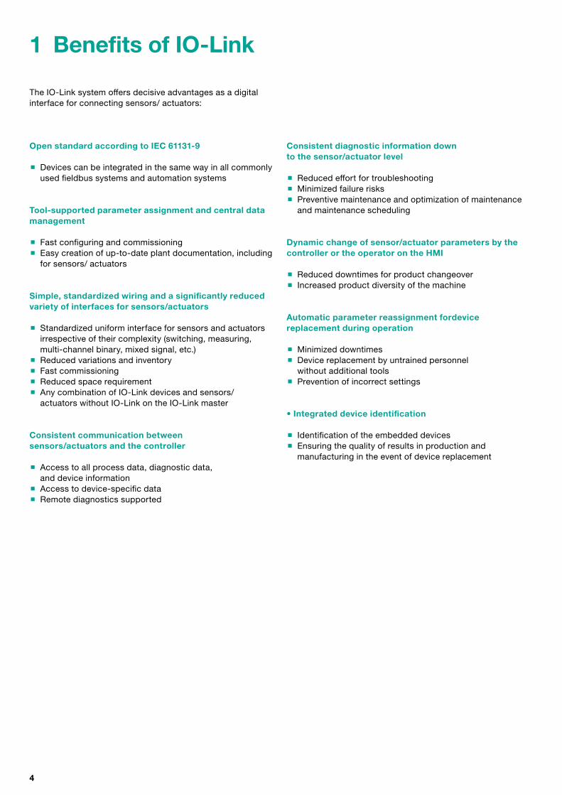
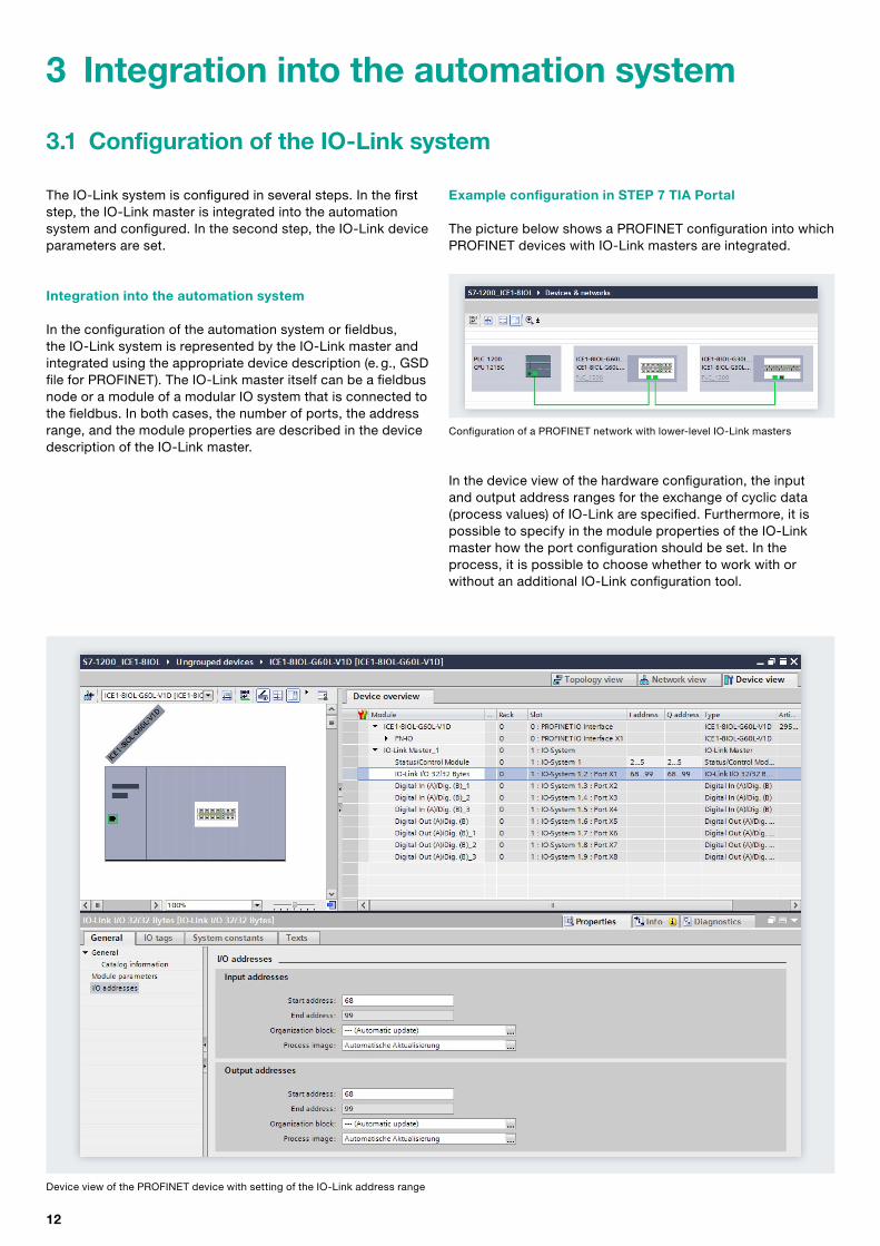
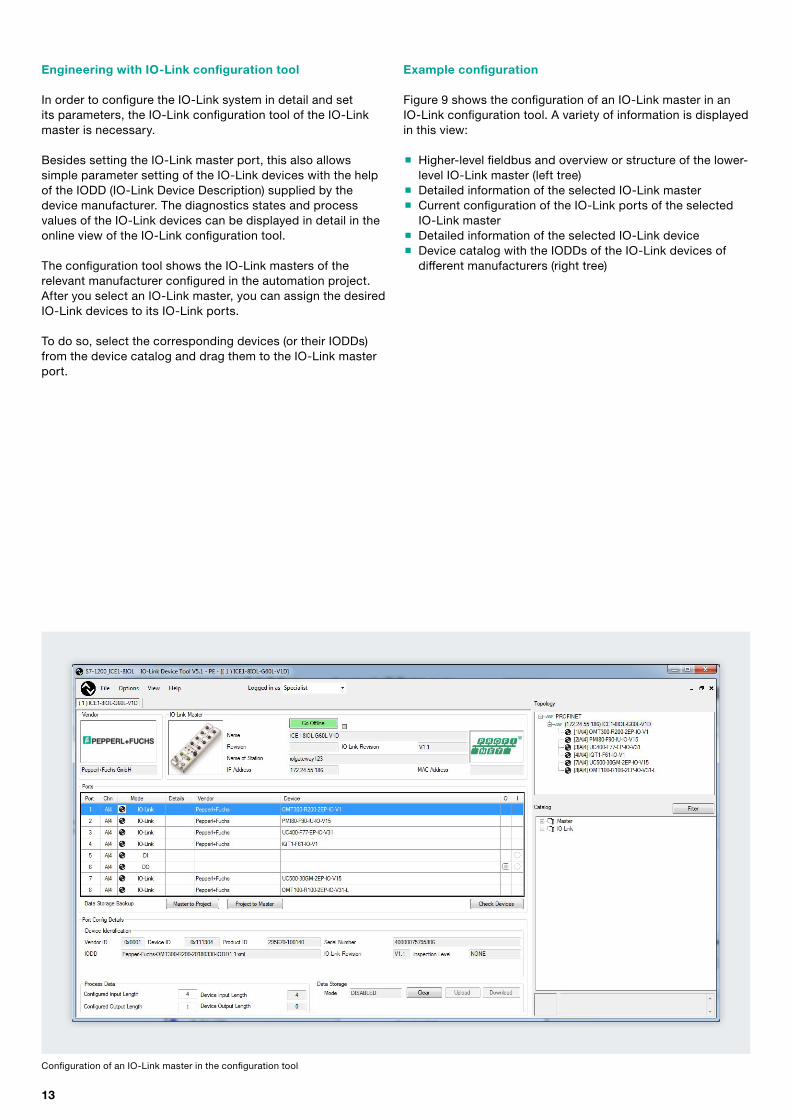

wwwpepperl-fuchscom Subject to modifications copy Pepperl+Fuchs 0220
Pepperl+Fuchs QualityDownload our latest policy here
wwwpepperl-fuchscomquality