manual kfu8-dw-1 - pepperl+fuchs
TRANSCRIPT
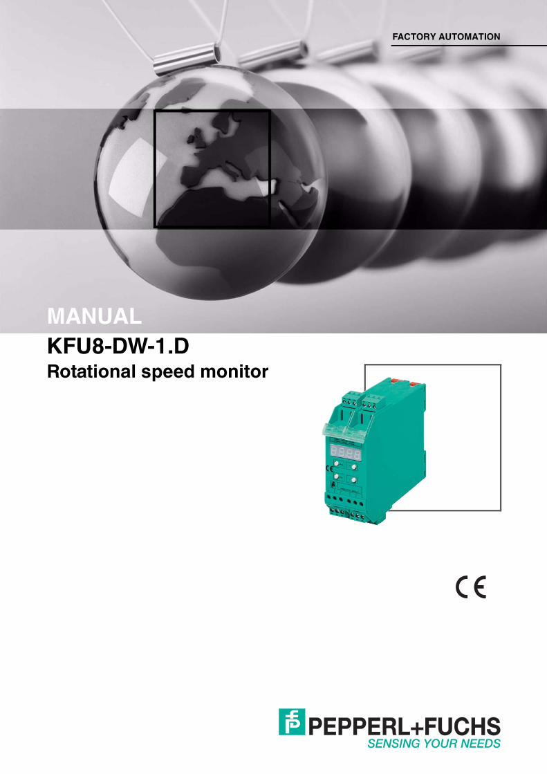
KFU8-DW-1.DRotational speed monitor
FACTORY AUTOMATION
MANUAL

With regard to the supply of products, the current issue of the following document is ap-plicable: The General Terms of Delivery for Products and Services of the Electrical Indus-
try, published by the Central Association of the Electrical Industry (Zentralverband Elektrotechnik und Elektroindustrie (ZVEI) e.V.) in its most recent version as well as the
supplementary clause: "Expanded reservation of proprietorship"
KFU8-DW-1.D
KFU8-DW-1.D
3
1 Safety ........................................................................................... 41.1 Introduction .......................................................................................... 4
1.1.1 Contents ............................................................................................ 41.1.2 Target Group, Personnel .................................................................... 41.1.3 Symbols Used.................................................................................... 4
2 Product Description ................................................................... 62.1 Device description ............................................................................... 6
3 Operation..................................................................................... 83.1 Operating mode ................................................................................... 83.2 Setup mode .......................................................................................... 93.3 Timer functions, reversing the detection direction of the output
relay10
4 Service and Maintenance ........................................................ 135 Anhang ...................................................................................... 14
5.1 Terminal assignment ......................................................................... 145.2 Dimensions, operating and display devices ................................... 145.3 Connection diagram .......................................................................... 155.4 Functional description....................................................................... 16
1295
06 20
16-9
KFU8-DW-1.DSafety
1 Safety1.1 Introduction1.1.1 Contents
This document contains information that you need in order to use your product throughout the applicable stages of the product life cycle. These can include the following:
■ Product identification■ Delivery, transport, and storage■ Mounting and installation■ Commissioning and operation■ Maintenance and repair■ Troubleshooting■ Dismounting■ Disposal
The documentation consists of the following parts:■ Present document■ Instruction manual■ Datasheet
Additionally, the following parts may belong to the documentation, if applicable:■ EU-type examination certificate■ EU declaration of conformity■ Attestation of conformity■ Certificates■ Control drawings■ Additional documents
1.1.2 Target Group, PersonnelResponsibility for planning, assembly, commissioning, operation, maintenance, and dismounting lies with the plant operator.Only appropriately trained and qualified personnel may carry out mounting, installation, commissioning, operation, maintenance, and dismounting of the product. The personnel must have read and understood the instruction manual and the further documentation.Prior to using the product make yourself familiar with it. Read the document carefully.
1.1.3 Symbols UsedThis document contains symbols for the identification of warning messages and of informative messages.
Note!This document does not substitute the instruction manual.
Note!For full information on the product, refer to the instruction manual and further documentation on the Internet at www.pepperl-fuchs.com.
4
KFU8-DW-1.DSafety
1295
06 20
16-9
Warning MessagesYou will find warning messages, whenever dangers may arise from your actions. It is mandatory that you observe these warning messages for your personal safety and in order to avoid property damage.Depending on the risk level, the warning messages are displayed in descending order as follows:
Informative Symbols
ActionThis symbol indicates a paragraph with instructions. You are prompted to perform an action or a sequence of actions.
Danger!This symbol indicates an imminent danger.Non-observance will result in personal injury or death.
Warning!This symbol indicates a possible fault or danger.Non-observance may cause personal injury or serious property damage.
Caution!This symbol indicates a possible fault.Non-observance could interrupt the device and any connected systems and plants, or result in their complete failure.
Note!This symbol brings important information to your attention.
5
1295
06 20
16-9
KFU8-DW-1.DProduct Description
2 Product Description2.1 Device description
The rotational speed monitor KFU8-DW-1.D is a device for displaying and monitoring periodical signals which occur in almost all areas of process automation, i.e. from general frequencies to specific speeds.The input signals are evaluated and converted into a frequency or speed by a powerful -controller in accordance with the cycle method.
Furthermore, in applications involving slow processes, where sensors deliver multiple pulses per revolution, it is possible to automatically operate with the actual speed of the drive by specifying the number of pulses per revolution.The measured value is displayed on a 7-segment LED display on the front of the device. The display has 4 digits and up to 3 decimal places. The parameterization is performed using the 4 buttons below the display.The monitoring function is actuated by a limiting value, whose upper and lower hysteresis values can be selected within the relevant measurement and indicating range.The output signal is generated by a changeover relay when the value exceeds or falls below the hysteresis limits. Due to its high switching capability, the relay output can be used to directly drive an actuator, or as an input signal to a higher level control.In addition, the switching state of the relay is indicated by a yellow LED on the front of the device.A function block is connected in line with the output relay, which enables 10 different timer functions to be employed; thus there is no need to connect a separate timer relay in series. In addition to ON delay, OFF delay, defined ON time and pulse expansion, the direction of operation of the relay can also be selected, i.e. to monitor underspeed or overspeed.The integral startup override is triggered when the supply voltage is switched on or by an external signal and prevents false signals from occurring when the monitored system starts up.The rotational speed monitor can be operated with a 24 VDC power supply.
Note!Close attention was paid to the special case of speed measurement during the development of the device. The indicators and inputs can therefore occur in Hz or in rpm.
Note!All currently available two, three or four-wire proximity switches and incremental rotary encoders are acceptable as sensors. Moreover, two terminals are reserved for the connection of proximity switches as per DIN 19234 (NAMUR).
Caution!Insulation co-ordinates for specifying data on galvanic/electrical isolation are in accordance with DIN EN 50178:The KFU8-DW-1.D device is intended for use in enclosed electrical operating areas, to which only competent electrical personnel or properly instructed electrotechnical personnel have access or entry.The device is designed for use in degree of pollution 2 and surge category II as per EN 50178.
6
KFU8-DW-1.DProduct Description
1295
06 20
16-9
The device comprises 3 galvanically isolated circuits:■ Signal circuit■ 24 V voltage supply, connections 4, 5■ Sensor/signal, connections 1, 2, 3, 7, 8, 9, 13, 14, 15■ Relay output circuit, connections 10, 11, 12
The circuits in this component device are separated from mains by reinforced/double insulation (basic + supplementary).There is no isolation between the signal circuit connections and the exposed/contactable surfaces.
7
1295
06 20
16-9
KFU8-DW-1.DOperation
3 Operation3.1 Operating mode
Signal frequencyThe rotational speed monitor processes input signals from 0.002 Hz ... 40 kHz, over 4 measurement ranges. Cycle durations of 25 µs to 500 s are evaluated. Signals not having a duty rate of 1:1 must have a minimum pulse pause or pulse duration of 12 s in order to be detected with certainty behind the input filter.
Measurement underrange, message This message appears either when no input signal is detected, or if the displayed value would be zero due to the selection of an excessively high measurement range.Example: The device receives a signal of 0.1 Hz in the 0 Hz ... 9999 Hz measurement and display range. This implies that the display would indicate zero and an observer might presume that the machine had stopped.
Measurement overrange, message The preset display and measurement range was exceeded.
Very low signal frequencies, displayed value is not valid, messageDuring the measurement of very low signal frequencies, the measuring system has detected that the signal has fallen below the last computed frequency. The time between the last two signal edges has already elapsed. The device is now waiting for the next positive signal edge in order to compute the next measured value. Here, 'XXX' represents the positions of the first three digits of the last measured value.
Self test, message When the power supply is switched on, the device performs a self test. The message appears when it is established that there is an error, for example during the check summation of the EEPROM data; in this state, the output relay behaves as if there has been a power failure. The error message can be cleared by switching the supply voltage off and on again.
Error message
1. Enter the parameters again.2. Switch the device off and back on again.
The normal function of the output relay is restored.
Note!Select a wider measurement range.
Note!If, when switching on again, the error message appears, then the factory presets were loaded.
8
KFU8-DW-1.DOperation
1295
06 20
16-9
3.2 Setup modeSee chapter 5.4
Function selection 2 measurement functions are available:
1. Frequency measurement in HzThe established cycle duration of the input signal is converted into a frequency in Hz through the formation of a reciprocal value and displayed. Specify the hysteresis limits of the switching point in Hz as well.
2. Rotational speed measurement in rpm (factory preset)The signal frequency calculated from the cycle duration is multiplied by 60 and displayed in rpm. Specify the hysteresis limits of the switching point in rpm.
Pulse divider (factory preset: 1 pulse/revolution)Applications involving slow processes are frequently equipped with sensors which provide several pulses per revolution. In the rotational speed measuring function, the device undertakes the conversion to the actual value of rpm by inputting the numerical value (of pulses/revolution), i.e. both the indication and the input of the hysteresis limits are obtained from the actual rate of rotation of the drive.Example: In normal operation, a machine rotates at 450 rpm. An incremental rotary encoder providing 10 pulses per revolution is used as the rate of rotation sensing element.The input frequency is:
A rate of rotation of 450 rpm x 10 pulses/revolution = 4500 rpmwould be displayed in the rotational speed measuring function.
By programming the pulse divider to 10 pulses/revolution, the display would indicate the actual drive speed of 450 rpm.
Display and measurement range (factory preset: 0 ... 999,9)Four measuring and display ranges are available for frequency measurement and three measuring and display ranges are available for speed measurement:Display in parameter editor
Frequency range in Hz Speed range in rpm
Number of decimal places
0000 0 ... 9999 0000.1 0,0 ... 999,9 100.02 0,0 ... 99,99 20.003 0,0 ... 9,999 ---- 3
450 rpm x 10 pulses/revolution60 s/min
= 75 Hz
9
1295
06 20
16-9
KFU8-DW-1.DOperation
Example:The maximum permissible rotational speed of the drive is 600.5 rpm. The first two measuring ranges can be selected. However, in order to fully utilize the accuracy of the display, it is recommended that the second measuring range be used.
Message This message appears when an attempt has been made to change the range in such a way that previously input limiting values lie outside the display and measuring range, or the respective places following the decimal point would be cut off.Example:You have already entered the maximum permitted speed of 600.5 rpm as the upper hysteresis limit and are attempting to change to the range 0.0 rpm ... 99.99 rpm (limit value outside of display and measurement range).Or:You are attempting to change to the range 0 rpm ... 9999 rpm (decimal point was removed).
Switching points of the output relay or (factory preset: 100 or 200)The output relay switching points are defined by the upper and lower hysteresis limit. When the upper hysteresis limit O_Gr is exceeded, a switching operation is triggered and on falling below the lower hysteresis limit U_Gr, a switch back operation occurs. If a hysteresis limit is not desired, enter the same value for both parameters. The output relay then switches both on and off at a defined speed.Example:On exceeding the maximum permissible rotational speed of 600.5 rpm signal should be activated in the control room. The alarm message should then extinguish when the speed drops below 500 rpm.Set the upper hysteresis limit to 600.5 rpm and the lower hysteresis limit to 500 rpm.
Message or The message GrU? appears if an attempt is made to set a value for the upper hysteresis limit which is lower than the lower hysteresis limit. The message GrO? appears if an attempt is made to display a value for the lower hysteresis value which is greater than the upper hysteresis limit.
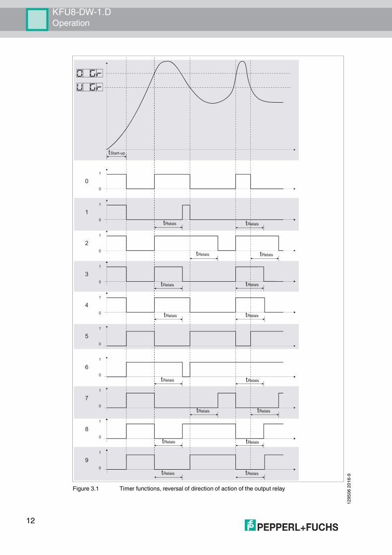
3.3 Timer functions, reversing the detection direction of the output relayTime base for the timer functions (factory preset: 1.0 s)A time between 0.1 s and 999.9 s can be set for the timer function of the output relay.
Timer function and reversing the detection direction (factory preset: 0)The KFU8-DW-1.D rotational speed monitor in combination with a reversal of the direction of action can be adjusted to any one of 10 different settings in order to modify the switching behavior of the output relay. In functions 0 to 4, the output relay is active according to the selected time function when the upper hysteresis value is exceeded. In functions 5 to 9, the detection direction is inverted, i.e. the relay is active below the lower hysteresis limit.No. Function No. Function
0 No timer function 5 No timer function, inverted1 ON delay 6 ON delay, inverted
10
KFU8-DW-1.DOperation
1295
06 20
16-9
The ON delay causes the timer to start when the upper hysteresis limit is exceeded and the relay to trigger (retriggerable) only when the timer has run out.The OFF delay causes the relay to operate immediately after the upper limiting value is exceeded. Each time the measured parameter falls below the lower limit, the timer is started and as soon as the timer runs out the relay switches off (retriggerable).defined ON time implies that the relay operates when the upper hysteresis limit is exceeded and switches off again after the preset time (not retriggerable) independently of further variations in rpm.Pulse extension ensures that the relay operates when the upper limit is exceeded and switches off again as soon as the preset time (not retriggerable) elapses. see Figure 3.1 on page 12
Startup override (factory preset: 1.5 s)A startup override time between 0.1 s and 999.9 s can be programmed in order to avoid false signals on the start-up of a drive that is being monitored for underspeed. During this time the device and the output relay behave as if the machine had already exceeded the upper hysteresis limit.The startup override time is started by a positive signal on terminal 2; the positive signal must be at least as long as the override time. The start signal can originate from a higher order control, or be generated by the connection of the power supply to the rotational speed monitor. In the latter case, terminals 2 and 3 have to be bridged.Example:In normal operation, a machine requires a maximum of 50 s to run up to a nominal speed of 500 rpm. Set the startup override time to a value greater than 50 s. When the period of 50 s has elapsed, the underspeed monitoring function (relay function 5) is active. If the startup runs according to plan within this time, the relay will not have actuated.If the startup takes longer than anticipated, then the relay will switch 50 s after commencement of the startup override, until the upper hysteresis limit has been reached.
Display rate (factory preset: 0.33 s)In order to ensure good readability of the display, the time taken to indicate the current measured value in the display can be selected between 0.01 s and 2.5 s.
Software version number
2 OFF delay 7 OFF delay, inverted3 Defined ON time 8 Defined ON time, inverted4 Pulse extension 9 Pulse extension, inverted
No. Function No. Function
Note!The display rate influences neither the time required to calculate the measured value nor the switching characteristics of the output relay.
Note!You can only read out the version number of the software.
11
1295
06 20
16-9
KFU8-DW-1.DOperation
Figure 3.1 Timer functions, reversal of direction of action of the output relay
tRelais
tRelais
tRelais
tRelais
tRelais
tRelais
tRelaistRelais
tRelais
tRelais
tRelais
tRelais
tRelais
tRelais
tRelais
tRelais
tStart-up
1
0
1
0
1
0
1
0
1
0
1
0
1
0
1
0
1
0
1
0
0
1
2
3
4
5
6
7
8
9
12
KFU8-DW-1.DService and Maintenance
1295
06 20
16-9
13
4 Service and Maintenance The device is designed and constructed to function stable over long periods of time. For this reason, regular cleaning or maintenance is unnecessary.
1295
06 20
16-9
KFU8-DW-1.DAnhang
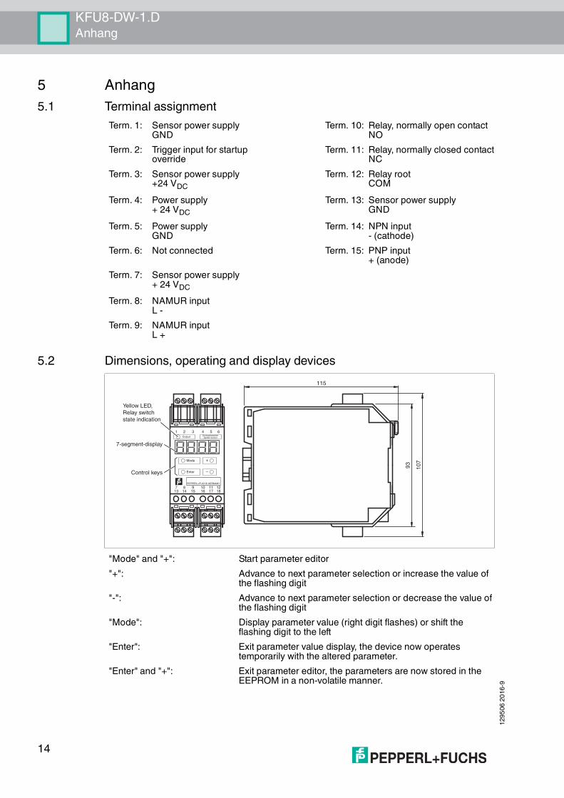
5 Anhang5.1 Terminal assignment
5.2 Dimensions, operating and display devices
Term. 1: Sensor power supplyGND
Term. 10: Relay, normally open contactNO
Term. 2: Trigger input for startup override
Term. 11: Relay, normally closed contactNC
Term. 3: Sensor power supply+24 VDC
Term. 12: Relay rootCOM
Term. 4: Power supply+ 24 VDC
Term. 13: Sensor power supplyGND
Term. 5: Power supplyGND
Term. 14: NPN input- (cathode)
Term. 6: Not connected Term. 15: PNP input+ (anode)
Term. 7: Sensor power supply+ 24 VDC
Term. 8: NAMUR inputL -
Term. 9: NAMUR inputL +
"Mode" and "+": Start parameter editor"+": Advance to next parameter selection or increase the value of
the flashing digit"-": Advance to next parameter selection or decrease the value of
the flashing digit"Mode": Display parameter value (right digit flashes) or shift the
flashing digit to the left"Enter": Exit parameter value display, the device now operates
temporarily with the altered parameter."Enter" and "+": Exit parameter editor, the parameters are now stored in the
EEPROM in a non-volatile manner.
Mode
Output DrehzahlwächterSpeed monitor
Enter
+
–
1 2 3 4 5 6
13 14 15 16 17 187 8 9 10 11 12
PEPPERL+FUCHS GERMANY
Control keys
7-segment-display
Yellow LED,Relay switchstate indication
107
93
115
14
KFU8-DW-1.DAnhang
1295
06 20
16-9
5.3 Connection diagram
Figure 5.1 Connection diagram
L+
L–89
L+
L–
151413
7
L+
L–89
L+
L– 13
71514
L+
L–
151413
7 L+
L– 13
71514
L+
L–
151413
7 L+
L–
L+16-30 V
0 V L–
1514
1514
13
7
yellow
NAMUR Sensor
NAMUR Encoder
DC-3-wire sensor, PNP
DC-3-wire sensor, NPN
DC-2-wire sensor, PNP
DC-2-wire sensor, NPN
Encoder, push-pull
Encoder, push-pull
Power supply 24 V DC
Power supply 230 V AC
Power supply 115 V AC
Not connected
Sensor power supply GND
Sensor power supply GND
Sensor power supply 24 V DC
Sensor power supply 24 V DC
Trigger input for start-up bypass
External trigger signal
Bridge fitted: start-up bypass triggered by switching on the power supply
Relay output
External rectangular signal
Galvanically isolated input
9NAMUR L+
NAMUR L-8
73
2
1
15
14
13
6
COM
NC
NO
4L+
5L-
16L1 (230 V)
17L1 (115 V)
18N
12
11
10
15
1295
06 20
16-9
KFU8-DW-1.DAnhang
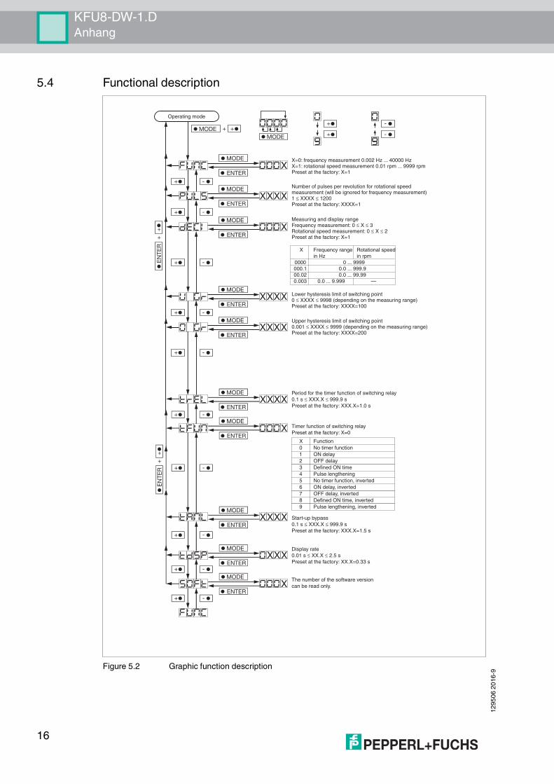
5.4 Functional description
Figure 5.2 Graphic function description
Operating mode
X=0: frequency measurement 0.002 Hz ... 40000 Hz X=1: rotational speed measurement 0.01 rpm ... 9999 rpm Preset at the factory: X=1
Number of pulses per revolution for rotational speed measurement (will be ignored for frequency measurement) 1 ≤ XXXX ≤ 1200Preset at the factory: XXXX=1
Measuring and display range Frequency measurement: 0 ≤ X ≤ 3Rotational speed measurement: 0 ≤ X ≤ 2Preset at the factory: X=1
Upper hysteresis limit of switching point 0.001 ≤ XXXX ≤ 9999 (depending on the measuring range)Preset at the factory: XXXX=200
Lower hysteresis limit of switching point 0 ≤ XXXX ≤ 9998 (depending on the measuring range)Preset at the factory: XXXX=100
Period for the timer function of switching relay 0.1 s ≤ XXX.X ≤ 999.9 sPreset at the factory: XXX.X=1.0 s
Timer function of switching relay Preset at the factory: X=0
Start-up bypass 0.1 s ≤ XXX.X ≤ 999.9 sPreset at the factory: XXX.X=1.5 s
Display rate0.01 s ≤ XX.X ≤ 2.5 sPreset at the factory: XX.X=0.33 s
The number of the software version can be read only.
X Function0 No timer function1 ON delay2 OFF delay3 Defined ON time 4 Pulse lengthening 5 No timer function, inverted 6 ON delay, inverted 7 OFF delay, inverted 8 Defined ON time, inverted9 Pulse lengthening, inverted
X Frequency range Rotational speedin Hz in rpm
0000 0 ... 9999000.1 0.0 ... 999.900.02 0.0 ... 99.990.003 0.0 ... 9.999 —
16

Subject to modifications Copyright PEPPERL+FUCHS • Printed in Germany
www.pepperl-fuchs.com
FACTORY AUTOMATION – SENSING YOUR NEEDS
Worldwide HeadquartersPepperl+Fuchs GmbH68307 Mannheim · GermanyTel. +49 621 776-0E-mail: [email protected]
USA HeadquartersPepperl+Fuchs Inc.Twinsburg, Ohio 44087 · USATel. +1 330 4253555E-mail: [email protected]
Asia Pacific HeadquartersPepperl+Fuchs Pte Ltd.Company Registration No. 199003130ESingapore 139942Tel. +65 67799091E-mail: [email protected]
129506 / DOCT0610D9/2016