is/iso 8528-1 (2005): reciprocating internal combustion engine
TRANSCRIPT

Disclosure to Promote the Right To Information
Whereas the Parliament of India has set out to provide a practical regime of right to information for citizens to secure access to information under the control of public authorities, in order to promote transparency and accountability in the working of every public authority, and whereas the attached publication of the Bureau of Indian Standards is of particular interest to the public, particularly disadvantaged communities and those engaged in the pursuit of education and knowledge, the attached public safety standard is made available to promote the timely dissemination of this information in an accurate manner to the public.
इंटरनेट मानक
“!ान $ एक न' भारत का +नम-ण”Satyanarayan Gangaram Pitroda
“Invent a New India Using Knowledge”
“प0रा1 को छोड न' 5 तरफ”Jawaharlal Nehru
“Step Out From the Old to the New”
“जान1 का अ+धकार, जी1 का अ+धकार”Mazdoor Kisan Shakti Sangathan
“The Right to Information, The Right to Live”
“!ान एक ऐसा खजाना > जो कभी च0राया नहB जा सकता है”Bhartṛhari—Nītiśatakam
“Knowledge is such a treasure which cannot be stolen”
“Invent a New India Using Knowledge”
है”ह”ह
IS/ISO 8528-1 (2005): Reciprocating Internal CombustionEngine Driven Alternating Current Generating Sets, Part 1:Application, Ratings and Performance [TED 2: AutomotivePrimemovers]

© BIS 2012
November 2012 Price Group 8
B U R E A U O F I N D I A N S T A N D A R D SMANAK BHAVAN, 9 BAHADUR SHAH ZAFAR MARG
NEW DELHI 110002
Hkkjrh; ekud
çR;kxkeh vkarfjd ngu batu pkfyr
IS/ISO 8528-1 : 2005
çR;korhZ èkkjk tujsfVax lsVHkkx 1 vuqç;ksx] jsfVax ,oa dk;Zdkfjrk
Indian StandardRECIPROCATING INTERNAL COMBUSTIONENGINE DRIVEN ALTERNATING CURRENT
GENERATING SETSPART 1 APPLICATION, RATINGS AND PERFORMANCE
ICS 27.020; 29.160.40
Automotive Primemovers Transmission and Steering Systems and Internal Combustion EnginesSectional Committee, TED 2
NATIONAL FOREWORD
This Indian Standard (Part 1) which is identical with ISO 8528-1 : 2005 ‘Reciprocating internalcombustion engine driven alternating current generating sets — Part 1: Application, ratings andperformance’ issued by the International Organization for Standardization (ISO) was adopted by theBureau of Indian Standards on the recommendation of the Automotive Primemovers Transmissionand Steering Systems and Internal Combustion Engines Sectional Committee and approval of theTransport Engineering Division Council.
The text of ISO Standard has been approved as suitable for publication as an Indian Standard withoutdeviations. Certain conventions are, however, not identical to those used in Indian Standards. Attentionis particularly drawn to the following:
a) Wherever the words ‘International Standard’ appear referring to this standard, they should beread as ‘Indian Standard’.
b) Comma (,) has been used as a decimal marker while in Indian Standards, the current practiceis to use a point (.) as the decimal marker.
This standard also makes a reference to the BIS Certification Marking. Details of which are given inNational Annex A.
In this adopted standard, reference appears to certain International Standards for which IndianStandards also exist. The corresponding Indian Standards which are to be substituted in their respectiveplaces are listed below along with their degree of equivalence for the editions indicated:
International Standard Corresponding Indian Standard Degree of Equivalence
ISO 3046-1 Reciprocating internalcombustion engines — Performance— Part 1: Declarations of power, fueland lubricating oil consumptions andtest methods — Addit ionalrequirements for engines for generaluseISO 8528-2 : 2005 Reciprocatinginternal combustion engine drivenalternating current generating sets —Part 2 : EnginesISO 8528-3 : 2005 Reciprocatinginternal combustion engine drivenalternating current generating sets —Part 3: Alternating current generatorsfor generating setsISO 8528-4 : 2005 Reciprocatinginternal combustion engine drivenalternating current generating sets —Part 4: Controlgear and switchgearISO 8528-5 : 2005 Reciprocatinginternal combustion engine drivenalternating current generating sets —Part 5: Generating sets
IS 10000 (Part 4) : 1980 Methods oftest for internal combustion engines:Part 4 Declarat ions of power,efficiency, fuel consumption andlubricating oil consumption
IS/ISO 8528-2 : 2005 Reciprocatinginternal combustion engine drivenalternating current generating sets:Part 2 EnginesIS/ISO 8528-3 : 2005 Reciprocatinginternal combustion engine drivenalternating current generating sets:Part 3 Alternating current generatorsfor generating setsIS/ISO 8528-4 : 2005 Reciprocatinginternal combustion engine drivenalternating current generating sets:Part 4 Controlgear and switchgearIS/ISO 8528-5 : 2005 Reciprocatinginternal combustion engine drivenalternating current generating sets:Part 5 Generating sets
Technically Equivalent
Identical
do
do
do
(Continued on third cover)
1 Scope
This part of ISO 8528 defines various classifications for the application, rating and performance of generating sets consisting of a Reciprocating Internal Combustion (RIC) engine, Alternating Current (a.c.) generator and any associated controlgear, switchgear and auxiliary equipment.
It applies to a.c. generating sets driven by RIC engines for land and marine use, excluding generating sets used on aircraft or to propel land vehicles and Iocomotives.
For some specific applications (e.g. essential hospital supplies, high-rise buildings) supplementary requirements may be necessary. The provisions of this part of ISO 8528 should be regarded as the basis for establishing any supplementary requirements.
For other reciprocating-type prime movers (e.g. sewage-gas engines, steam engines), the provisions of this part of ISO 8528 should be used as a basis for establishing these requirements.
Generating sets meeting the requirements of this International Standard are used to generate electrical power for continuous, peak-load and standby applications. The classifications laid down in this part of ISO 8528 are intended to help understanding between manufacturer and customer.
2 Normative references
The following referenced documents are indispensable for the application of this document. For dated references, only the edition cited applies. For undated references, the latest edition of the referenced document (including any amendments) applies.
ISO 3046-1, Reciprocating internal combustion engines — Performance — Part 1: Declarations of power, fuel and lubricating oil consumptions, and test methods — Additional requirements for engines for general use
ISO 8528-22), Reciprocating internal combustion engine driven alternating current generating sets — Part 2: Engines
ISO 8528-32), Reciprocating internal combustion engine driven alternating current generating sets — Part 3: Alternating current generators for generating sets
ISO 8528-42), Reciprocating internal combustion engine driven alternating current generating sets — Part 4: Controlgear and switchgear
ISO 8528-52), Reciprocating internal combustion engine driven alternating current generating sets — Part 5: Generating sets
2) ISO 8528-2, 3, 4 and 5 are all under revision.
Indian StandardRECIPROCATING INTERNAL COMBUSTIONENGINE DRIVEN ALTERNATING CURRENT
GENERATING SETSPART 1 APPLICATION, RATINGS AND PERFORMANCE
IS/ISO 8528-1 : 2005
1
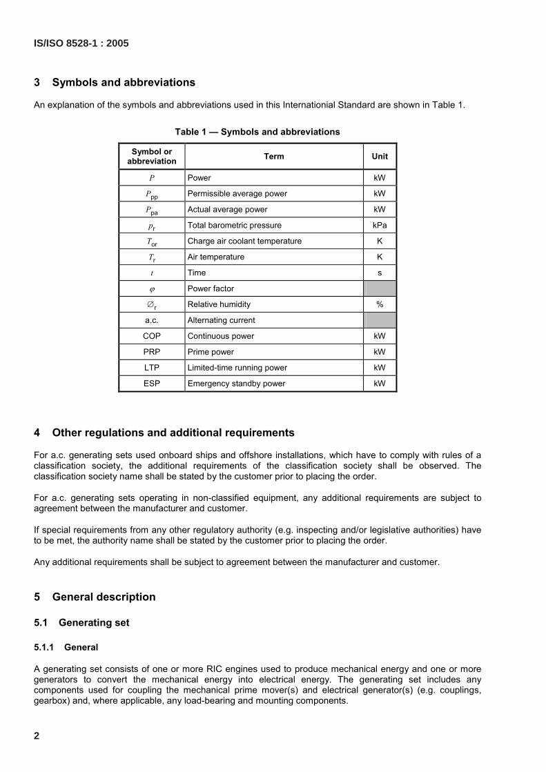
3 Symbols and abbreviations
An explanation of the symbols and abbreviations used in this Internationial Standard are shown in Table 1.
Table 1 — Symbols and abbreviations
Symbol or abbreviation Term Unit
P Power kW
Ppp Permissible average power kW
Ppa Actual average power kW
pr Total barometric pressure kPa
Tor Charge air coolant temperature K
Tr Air temperature K
t Time s
ϕ Power factor
∅r Relative humidity %
a.c. Alternating current
COP Continuous power kW
PRP Prime power kW
LTP Limited-time running power kW
ESP Emergency standby power kW
4 Other regulations and additional requirements
For a.c. generating sets used onboard ships and offshore installations, which have to comply with rules of a classification society, the additional requirements of the classification society shall be observed. The classification society name shall be stated by the customer prior to placing the order.
For a.c. generating sets operating in non-classified equipment, any additional requirements are subject to agreement between the manufacturer and customer.
If special requirements from any other regulatory authority (e.g. inspecting and/or legislative authorities) have to be met, the authority name shall be stated by the customer prior to placing the order.
Any additional requirements shall be subject to agreement between the manufacturer and customer.
5 General description
5.1 Generating set
5.1.1 General
A generating set consists of one or more RIC engines used to produce mechanical energy and one or more generators to convert the mechanical energy into electrical energy. The generating set includes any components used for coupling the mechanical prime mover(s) and electrical generator(s) (e.g. couplings, gearbox) and, where applicable, any load-bearing and mounting components.
2
IS/ISO 8528-1 : 2005
5.1.2 Prime movers
For the purposes of this International Standard, prime movers may be of two types:
a) compression-ignition engines; and
b) spark-ignition engines.
Depending on the generating set application, the following criteria, among others, may be important in selecting the prime mover to be used:
a) quality of fuel and fuel consumption;
b) exhaust gas and noise emission;
c) speed range;
d) mass and dimensions;
e) sudden electrical loading and frequency behaviour;
f) generator short-circuit characteristics;
g) cooling systems;
h) starting systems;
i) maintenance requirements;
j) waste heat utilization.
5.1.3 Electrical generators
For the purposes of this International Standard, electrical generators may be of two types:
a) synchronous; and
b) asynchronous.
Depending on the generating set application, the following criteria, among others, may be important in selecting the generator to be used:
a) voltage characteristics during starting and normal operation as well as after load changes, taking into account the electrical power factor;
b) short-circuit behaviour (electrical and mechanical);
c) efficiency;
d) generator design and enclosure type;
e) parallel-operation behaviour;
f) maintenance requirements.
5.1.4 Control and switchgear
Equipment for the control, switching, operation and monitoring of the generating set shall be part of the associated controlgear and switchgear systems.
IS/ISO 8528-1 : 2005
3
5.1.5 Auxiliaries
Auxiliaries are items of equipment additional to those already fitted/installed on the generating set as supplied but essential to its proper and safe operation, such as:
a) starting system;
b) air intake and exhaust gas systems;
c) cooling systems;
d) lubricating oil system;
e) fuel system (including fuel treatment where applicable);
f) auxiliary electrical power supply.
5.2 Power Station
A power station comprises an installation of one or more generating sets and their auxiliary equipment, the associated controlgear and switchgear and, where applicable, the place of installation (e.g. a building, an enclosure or special equipment for protection from the weather).
6 Application criteria
6.1 Modes of operation
6.1.1 General
The generating set mode of operation may affect certain important performance characteristics (e.g. its economical and reliable operation, the intervals between maintenance and repair) and shall be taken into account by the customer when agreeing the requirements with the manufacturer (see Clause 11).
6.1.2 Continuous operation at constant load
Continuous operation at constant load is defined as operation of a generating set without time limit taking into account the maintenance period, where the applied electrical load is constant.
EXAMPLE Providing a base load for a combined heat and power plant.
6.1.3 Continuous operation at varying load
Continuous operation at varying load is defined as operation of a generating set without time limit, taking into account the maintenance period, where the applied electrical load is variable.
EXAMPLE Providing electrical power where there is no utility electrical power available or the utility electrical supply is uncertain.
6.1.4 Limited time operation at constant load
Limited time operation at constant load is defined as operation of a generating set within set time limits where the applied electrical load is constant.
EXAMPLE Peak shaving load management where a generating set operating in parallel with a utility supply takes a constant load during periods of peak power consumption.
4
IS/ISO 8528-1 : 2005
6.1.5 Limited time operation at varying load
Limited time operation at varying load is defined as operation of a generating set within set time limits where the applied electrical load is variable.
EXAMPLE To provide a basic support function to a building electrical supply in the event of normal utility supply failure.
6.2 Site criteria
6.2.1 Land use
Land use applies to generating sets either fixed, transportable or mobile which are used on land.
6.2.2 Marine use
Marine use applies to generating sets used on board ships and offshore installations.
6.3 Single and parallel operation
6.3.1 General
Generating sets may have two types of operation as follows:
a) Single Operation:
This applies to generating sets, irrespective of their configuration or mode of start-up and control, which will operate as the sole source of electrical power;
b) Parallel Operation:
This refers to the electrical connection of a generating set to another source of electrical supply with the same voltage, frequency and phase to share the power supply demand for the connected network. The characteristics of the normal utility electrical power supply, including voltage range and variation, frequency, impedance of the network, etc., shall be stated by the customer.
6.3.2 Generating set parallel operation
In this type of operation, two or more generating sets are electrically connected (not mechanically connected) after having been brought into synchronism. Generating sets with different outputs and speeds can be used.
6.3.3 Generating set operation in parallel with a utility supply
In this type of operation, one or more generating sets operating in parallel (as described in 6.3.1) are electrically connected to a utility supply.
In the case of public utility electrical power supply, permission for parallel operation has to be obtained from the public utility electricity authority. Protective equipment has to be provided in accordance with the public regulations in force at the time.
NOTE This also applies to generating sets which, in order to periodically check their start-up function, have to operate by supplying power into the normal electrical power supply system for a time period laid down by the generating set manufacturer.
IS/ISO 8528-1 : 2005
5
6.4 Modes of start-up and control
6.4.1 General
The modes of start-up and control involved in the operation of a generating set are normally:
a) starting;
b) monitoring;
c) voltage and frequency adjustment and synchronization where applicable;
d) switching;
e) stopping.
These can be fully or partly manual, or automatic (see ISO 8528-4).
6.4.2 Manual operation
Manual operation applies to generating sets which are started and controlled manually.
6.4.3 Semi-automatic operation
Semi-automatic operation applies to generating sets in which some of its functions are started and controlled manually and the remainder automatically.
6.4.4 Automatic operation
Automatic operation applies to generating sets which are started and controlled completely automatically.
6.5 Start-up time
6.5.1 General
The start-up time is defined as the elapsed time between the instant when power is first demanded and the instant when it is first available. The start-up time is usually specified in seconds. The start-up time shall meet the requirement of the particular application in which the generating set is being used.
6.5.2 Generating set with no specified start-up time
This is a generating set where, due to the conditions under which it operates, the start-up time is of no importance. Such generating sets are normally started manually.
6.5.3 Generating set with a specified start-up time
This is a generating set where the start-up time is specified. Such generating sets are normally started automatically. Such generating sets may be further classified as follows:
6.5.3.1 Long-break
This is a generating set with a specified start-up time. The elapsed time between power supply failure and power from the generating set becoming available is fairly long. In this case, the entire generating set is started from the stationary condition after electrical power is demanded.
6
IS/ISO 8528-1 : 2005
6.5.3.2 Short-break
This is a generating set operating with rotating electrical machines where the electrical power supply is interrupted for a specific time (usually defined in milliseconds) while the necessary electrical transfer takes place. A source of stored mechanical energy is used to supply power to the rotating electrical machines for a short period and, where necessary, to start and accelerate the RIC engine.
6.5.3.3 No-break
This is a generating set operating with continuously running electrical machines so as to ensure an uninterrupted supply of electrical power in the event of utility failure. A source of stored mechanical energy is used to supply power to the connected equipment for a short period and, where necessary, to start and accelerate the RIC engine. As the drive is transferred from one power source to another, there may be a temporary deviation in frequency.
NOTE It is essential that the size of the permitted deviation in frequency during the transfer is agreed between the customer and manufacturer.
7 Performance classes
Four performance classes are defined in order to cover the various requirements of the supplied electrical systems as follows:
a) Class G1
This applies to generating set applications where the connected loads are such that only basic parameters of voltage and frequency need to be specified.
EXAMPLE General-purpose applications (lighting and other simple electrical loads).
b) Class G2
This applies to generating set applications where its voltage characteristics are very similar to those for the commercial public utility electrical power system with which it operates. When load changes occur, there may be temporary but acceptable deviations of voltage and frequency.
EXAMPLE Lighting systems, pumps, fans and hoists.
c) Class G3
This applies to applications where the connected equipment makes severe demands on the stability and level of the frequency, voltage and waveform characteristics of the electrical power supplied by the generating set.
EXAMPLE Telecommunications and thyristor-controlled loads. It should be remembered that both rectifier and thyristor-controlled loads may need special consideration with respect to their effect on generator-voltage waveform.
d) Class G4
This applies to applications where the demands made on the stability and level of the frequency, voltage and waveform characteristics of the electrical power supplied by the generating set are exceptionally severe.
EXAMPLE Data-processing equipment or computer systems.
IS/ISO 8528-1 : 2005
7
8 Installation features
8.1 General
Requirements to meet local regulations may affect the design and installation of the generating set and shall be taken into account by the customer and manufacturer in addition to the requirements shown in 8.2 to 8.6.
8.2 Installation configurations
8.2.1 General
The installation configurations in 8.2.2 to 8.2.4 may or may not have all the necessary generating set auxiliary equipment integrally mounted.
8.2.2 Fixed
This configuration applies to generating sets which are permanently installed.
8.2.3 Transportable
This configuration applies to generating sets which are not permanently installed or are mobile.
8.2.4 Mobile
This configuration applies to generating sets which have an integral chassis fitted with wheels whereby the generating set can be moved from one location to another.
8.3 Generating set configurations
In order to simplify the contractual information required for specifying RIC engine driven generating set applications, application configurations are as follows:
A: without baseframe;
B: with baseframe;
C: with baseframe, integrally mounted controlgear, switchgear and auxiliaries;
D: configuration as given in C with enclosure (see Clause 9);
E: configuration as given in C having an integral set of wheels or mounted on a trailer (see 8.2.4).
8.4 Mounting types
The type of mounting to be used for the generating set shall be agreed between the customer and the generating set manufacturer. Some typical types of mounting are:
a) Rigid:
In this type of installation, the generating set is installed on inflexible mounts. If foundations for mounting the generating set are installed on substrates of low elasticity (e.g. cork tiles) with no resilient layers inserted, the method of mounting is considered to be rigid.
b) Resilient:
In this type of installation, the generating set is installed on resilient mountings that are able to, depending upon their characteristics, partially insulate it from vibration. For special applications (e.g. marine or mobile) restrained resilient mountings may be required.
8
IS/ISO 8528-1 : 2005
1) Fully resilient:
In this type of installation, the generating set is mounted on a baseframe or a foundation fitted with mountings that provide insulation against vibration to a high level as agreed between the manufacturer and the customer.
2) Semi-resilient:
In this type of installation, the RIC engine is mounted resiliently and the electrical generator is mounted rigidly on a baseframe or foundation.
c) Mounting on resilient foundation:
In this type of installation, the generating set is mounted on a resilient foundation (damping mass) which is isolated from the load-bearing foundation by, for example, anti-vibration mounts.
8.5 Connection between the RIC engine and electrical generator
8.5.1 General
The mechanical connection between the RIC engine and the electrical generator is determined by the level of power to be transmitted and the configuration of the installation. It is affected by such parameters as the design of the engine, design of the generator, mounting type, the power to be transmitted, speed of rotation, out-of-balance requirements and whether a gearbox is used.
8.5.2 Coupling arrangements
Typical coupling arrangements are rigid, torsionally rigid, flexible, torsionally flexible or through a clutch.
8.5.3 Assembly arrangements
The assembly between the RIC engine and the electrical generator may be with or without the use of a flange housing.
8.6 Additional installation features — Weather effects
8.6.1 Inside installation
In this type of installation, the generating set is installed in a closed environment where it is not exposed to the direct effects of the weather. Careful consideration shall be given to the maximum and minimum temperatures expected in the operating environment.
8.6.2 Outside installation with protection from weather
In this type of installation, the generating set is installed in an environment where it may be partially exposed to the direct effects of the weather. The generating set may be installed in a closed, but not permanent, protective enclosure or under a protective roof.
8.6.3 Open-air installation
In this type of installation, the generating set is installed in an environment which is fully exposed to the direct effects of the weather.
IS/ISO 8528-1 : 2005
9
9 Emissions
When a generating set operates, it produces various emissions including noise, vibration, heat, gas and electromagnetic disturbance.
Any applicable legislation relating to the protection of the environment and to the health and safety of personnel operating or maintaining the generating set shall be taken into account by the manufacturer and customer at the time of agreeing to the performance specification.
10 Standard reference conditions
For the purpose of determining the rated power output of the generating set, the following standard reference conditions shall be used:
Total barometric pressure: pr = 100 kPa;
Air ambient temperature: Tr = 298 K (tr = 25 °C);
Relative humidity: ∅r = 30 %.
11 Site conditions
11.1 General
The site conditions under which a generating set is required to operate may affect certain characteristics and shall be taken into account by the customer and manufacturer when agreeing to the contract.
The prevailing site conditions shall be clearly specified by the customer and any particular hazardous conditions (e.g. explosive atmospheres or flammable gases) shall be described. Such characteristics may include but are not limited to those indicated in 11.2 to 11.10.
11.2 Ambient temperature
The customer shall inform the manufacturer of the upper and the lower ambient temperature limits at the site where the generating set will be installed and operated.
11.3 Altitude
The customer shall inform the manufacturer of the altitude above sea level of the site where the generating set will be installed and operated. However, it is preferable to provide the typical upper and lower limits of the barometric pressure experienced on site.
11.4 Humidity
The customer shall inform the manufacturer of the typical upper and lower values of humidity related to the temperature and pressure experienced on site (see 11.2 and 11.3).
11.5 Air quality
The customer shall inform the manufacturer if the generating set is required to operate in a polluted atmosphere (e.g. sand or dust). Special requirements may have to be applied in order to obtain satisfactory generating set performance and operation. Any increased maintenance requirements necessary to ensure trouble-free generating set operation due to these conditions should be noted by the customer.
10
IS/ISO 8528-1 : 2005
11.6 Marine environment
Special consideration is necessary when generating sets are required to operate in a marine environment. This may also apply to generating sets on land but installed and operated at a coastal site. The ambient environment of the generating set installation area shall be clearly defined by the customer.
11.7 Shock and imposed vibration
It shall be clearly stated by the customer if the generating set is required to operate under conditions where external shock and/or vibration may occur (e.g. in an earthquake area or where externally imposed vibration from an adjacent source is possible).
11.8 Chemical pollution
If the generating set is required to operate under conditions where chemical pollution exists, the nature and extent of the pollution shall be clearly stated by the customer.
11.9 Radiation
Various kinds of radiation may affect components of the generating set. As a result some components/assemblies may need special protection and/or a special maintenance programme in order to ensure trouble-free operation. The nature and extent of the radiation shall be clearly stated by the customer.
11.10 Cooling water/liquid
If the generating set has water/liquid cooled heat exchangers, the customer shall state the minimum and maximum temperatures (and, where necessary, the chemical composition and quantity) of the secondary (external) transfer liquid provided.
12 Power adjustment for operating conditions
To determine the appropriate generating set power ratings, the customer shall specify the operating conditions prevailing at the site as follows:
a) the barometric pressure (highest and lowest readings available or, if no pressure data are available, the altitude above sea level);
b) the monthly mean, minimum and maximum air temperatures during the hottest and coldest months of the year;
c) the highest and lowest ambient air temperatures around the engine;
d) the relative humidity (or alternatively the water vapour pressure or the wet and dry bulb temperature) ruling at the maximum temperature conditions;
e) the maximum and minimum temperatures of the cooling water available.
Where the site operating conditions differ from the standard reference conditions given in Clause 10, any necessary adjustment to the generating set power shall be made in order to determine the site rated power of the generating set.
For generating sets that are to be installed on board ships and intended for unrestricted service in accordance with the International Association of Classification Societies (IACS) requirements, the rated power shall be based on the nominal ambient conditions as specified in ISO 3046-1.
IS/ISO 8528-1 : 2005
11
13 Power rating definitions
13.1 General
The power of the generating set is the power output available for consumer loads at the generating set terminals excluding the electrical power absorbed by the essential independent auxiliaries (see 5.1 of ISO 8528-2 and Clause 5 of ISO 8528-3)
13.2 Power ratings
Generating set power ratings shall be expressed in kilowatts (kW) at its rated frequency and a power factor (cos ϕ) of 0,8 lagging unless otherwise stated.
Generating set power rating categories are necessary for inclusion in the manufacturer’s declaration of the power which the generating set will deliver under the agreed installation and operating conditions.
The power rating categories declared by the generating set manufacturer shall be used. No other category shall be used unless agreed between the customer and manufacturer.
13.3 Power rating categories
The generating set manufacturer shall be responsible for determining the power output in accordance with the requirements of 13.3.1 to 13.3.4 (see Figures 1 to 4) and recognizing the maintenance schedules and service procedures specified by the engine, a.c. generator and controlgear and switchgear manufacturers.
NOTE The user should be made aware that if any of the conditions regarding power output are not fulfilled, the generating set life will be reduced.
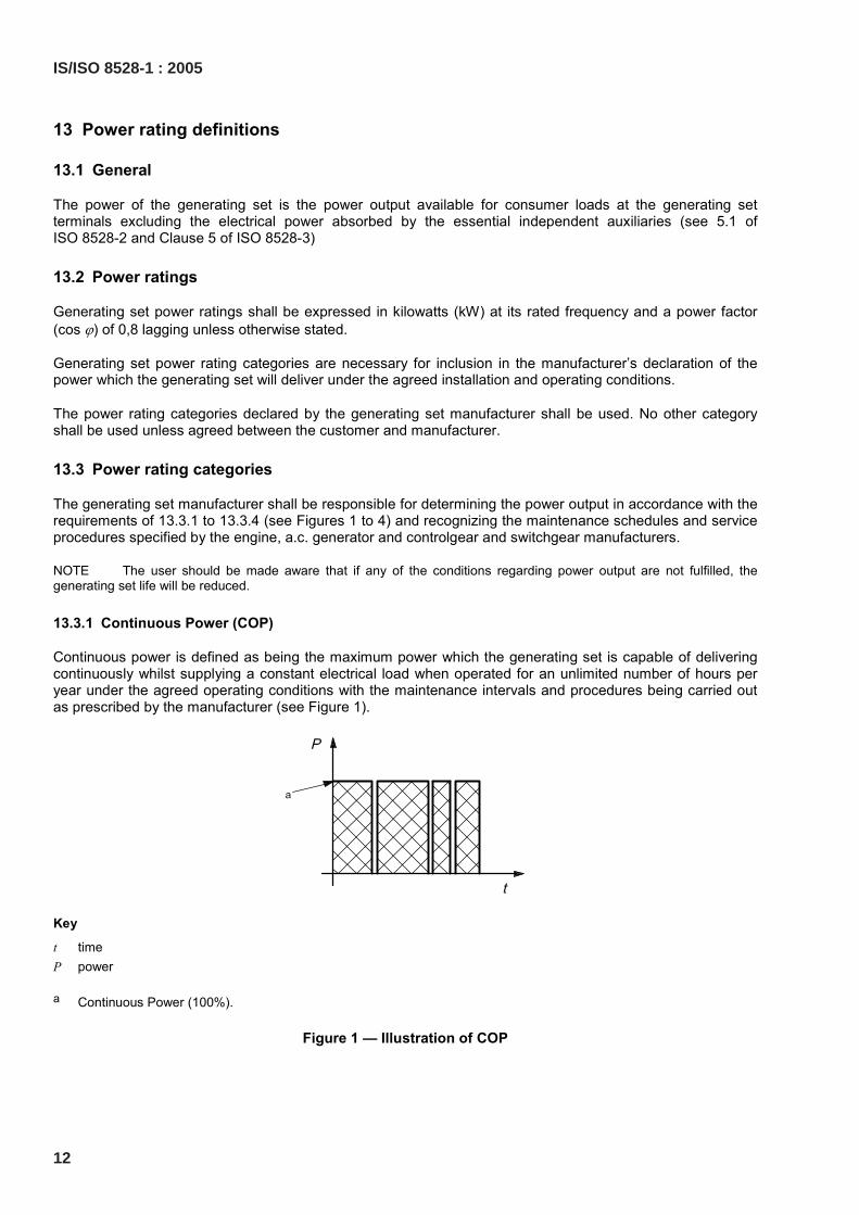
13.3.1 Continuous Power (COP)
Continuous power is defined as being the maximum power which the generating set is capable of delivering continuously whilst supplying a constant electrical load when operated for an unlimited number of hours per year under the agreed operating conditions with the maintenance intervals and procedures being carried out as prescribed by the manufacturer (see Figure 1).
Key
t time P power
a Continuous Power (100%).
Figure 1 — Illustration of COP
12
IS/ISO 8528-1 : 2005
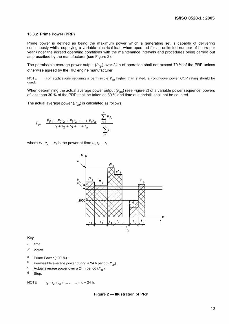
13.3.2 Prime Power (PRP)
Prime power is defined as being the maximum power which a generating set is capable of delivering continuously whilst supplying a variable electrical load when operated for an unlimited number of hours per year under the agreed operating conditions with the maintenance intervals and procedures being carried out as prescribed by the manufacturer (see Figure 2).
The permissible average power output (Ppp) over 24 h of operation shall not exceed 70 % of the PRP unless otherwise agreed by the RIC engine manufacturer.
NOTE For applications requiring a permissible Ppp higher than stated, a continuous power COP rating should be used.
When determining the actual average power output (Ppa) (see Figure 2) of a variable power sequence, powers of less than 30 % of the PRP shall be taken as 30 % and time at standstill shall not be counted.
The actual average power (Ppa) is calculated as follows:
1 1 2 2 3 3 1pa
1 2 3
1
......
n
i in n i
nni
i
P tP t P t P t P tP
t t t tt
=
=
+ + + += =
+ + + +
∑
∑
where P1, P2 … Pi is the power at time t1, t2 … ti.
Key
t time P power
a Prime Power (100 %). b Permissible average power during a 24 h period (Ppp). c Actual average power over a 24 h period (Ppa). d Stop.
NOTE t1 + t2 + t3 + … … … + tn = 24 h.
Figure 2 — Illustration of PRP
IS/ISO 8528-1 : 2005
13
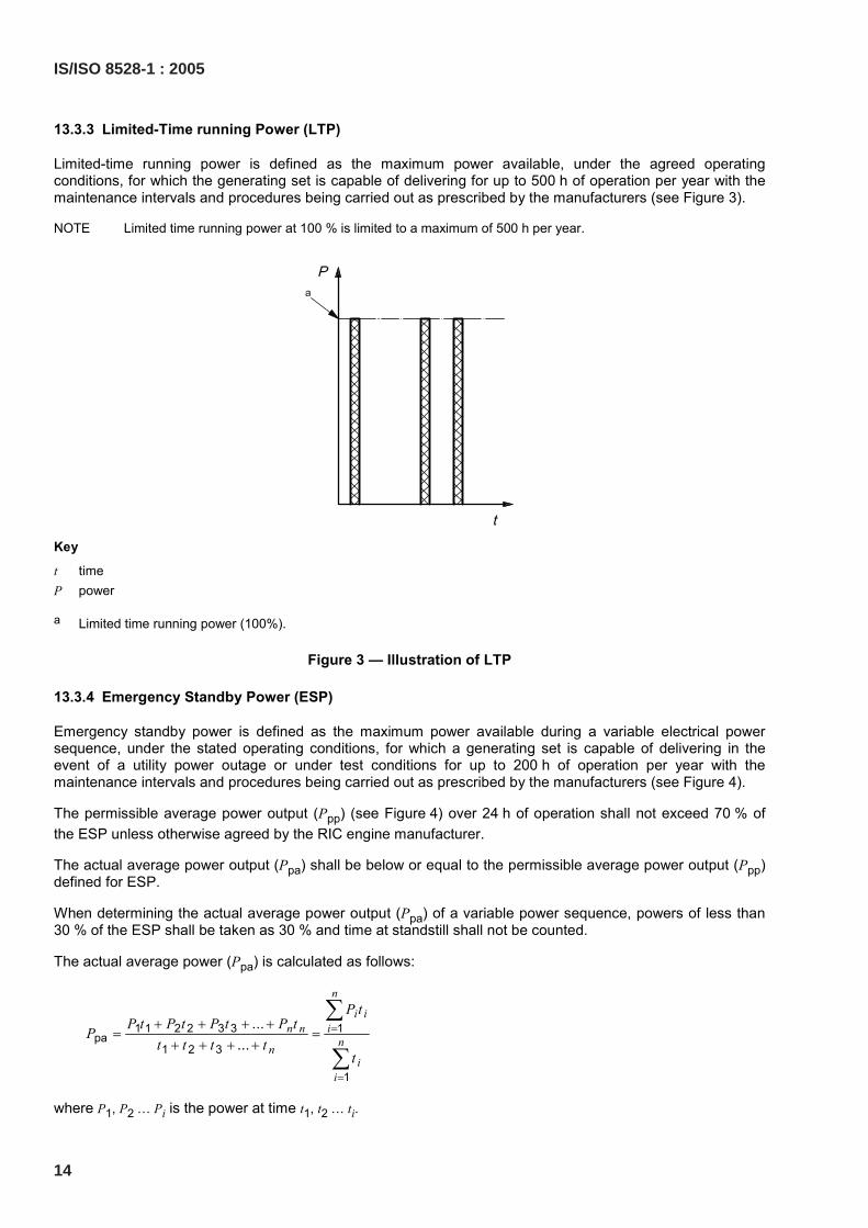
13.3.3 Limited-Time running Power (LTP)
Limited-time running power is defined as the maximum power available, under the agreed operating conditions, for which the generating set is capable of delivering for up to 500 h of operation per year with the maintenance intervals and procedures being carried out as prescribed by the manufacturers (see Figure 3).
NOTE Limited time running power at 100 % is limited to a maximum of 500 h per year.
Key
t time P power
a Limited time running power (100%).
Figure 3 — Illustration of LTP
13.3.4 Emergency Standby Power (ESP)
Emergency standby power is defined as the maximum power available during a variable electrical power sequence, under the stated operating conditions, for which a generating set is capable of delivering in the event of a utility power outage or under test conditions for up to 200 h of operation per year with the maintenance intervals and procedures being carried out as prescribed by the manufacturers (see Figure 4).
The permissible average power output (Ppp) (see Figure 4) over 24 h of operation shall not exceed 70 % of the ESP unless otherwise agreed by the RIC engine manufacturer.
The actual average power output (Ppa) shall be below or equal to the permissible average power output (Ppp) defined for ESP.
When determining the actual average power output (Ppa) of a variable power sequence, powers of less than 30 % of the ESP shall be taken as 30 % and time at standstill shall not be counted.
The actual average power (Ppa) is calculated as follows:
1 1 2 2 3 3 1pa
1 2 3
1
......
n
i in n i
nni
i
P tP t P t P t P tP
t t t tt
=
=
+ + + += =
+ + + +
∑
∑
where P1, P2 … Pi is the power at time t1, t2 … ti.
14
IS/ISO 8528-1 : 2005
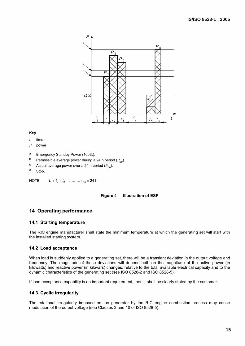
Key
t time P power
a Emergency Standby Power (100%). b Permissible average power during a 24 h period (Ppp). c Actual average power over a 24 h period (Ppa). d Stop.
NOTE t1 + t2 + t3 + ………+ tn = 24 h
Figure 4 — Illustration of ESP
14 Operating performance
14.1 Starting temperature
The RIC engine manufacturer shall state the minimum temperature at which the generating set will start with the installed starting system.
14.2 Load acceptance
When load is suddenly applied to a generating set, there will be a transient deviation in the output voltage and frequency. The magnitude of these deviations will depend both on the magnitude of the active power (in kilowatts) and reactive power (in kilovars) changes, relative to the total available electrical capacity and to the dynamic characteristics of the generating set (see ISO 8528-2 and ISO 8528-5).
If load acceptance capability is an important requirement, then it shall be clearly stated by the customer.
14.3 Cyclic irregularity
The rotational irregularity imposed on the generator by the RIC engine combustion process may cause modulation of the output voltage (see Clauses 3 and 10 of ISO 8528-5).
IS/ISO 8528-1 : 2005
15
14.4 Generator temperature rise
The generator winding temperature rise may be an important factor in Iimiting the long-term reliability of the generating set.
An increase in allowable temperature rise may be possible if the generating set is to be used on a limited time basis (see 6.2 of ISO 8528-3).
14.5 Fuel and lubricating oil characteristics and consumption
The manufacturer shall state the characteristics and consumption of fuel and lubricating oil to be used in the generating set. If verification of fuel consumption is required, the method of measurement shall be agreed between the customer and manufacturer, as outlined in ISO 3046-1.
Statements of generating set fuel consumption shall be made with reference to the electrical power available at the output terminals, taking into account the electrical power required for driving the essential independent auxiliaries (see ISO 3046-1) and the power loss in the a.c. generator for a given power and power factor. The lower calorific value of the fuel shall be stated.
14.6 Minimum running hours
The capacity of fuel and lubricating oil tanks may impose a limit on generating set running time.
Where such tanks are provided, the manufacturer shall state the generating set minimum running time without fuel and lubricating oil tank replenishment.
14.7 Regulation
14.7.1 Frequency regulation
The steady-state and transient electrical frequency regulation requirements may be an important consideration when specifying generating set performance. If this is the case, then it shall be clearly stated by the customer.
14.7.2 Voltage regulation
It is necessary to consider both steady-state and transient voltage regulation when specifying a generating set. It must also be noted that the nature of the electrical load current waveform imposed on the generating set may affect the output voltage waveform and steady-state voltage accuracy. If voltage regulation is an important requirement, it shall be clearly stated by the customer.
16
IS/ISO 8528-1 : 2005

Bibliography
[1] ISO 15550:2002, Internal combustion engines — Determination and method for the measurement of engine power — General requirements
IS/ISO 8528-1 : 2005
17
NATIONAL ANNEX A(National Foreword)
A-1 BIS CERTIFICATION MARKING
RIC engine driven ac generating set may also be marked with the Standard Mark.
A-1.1 The use of the Standard Mark is governed by the provisions of the Bureau of Indian StandardsAct, 1986 and the Rules and Regulations made thereunder. The details of conditions under which thelicence for the use of the Standard Mark may be granted to manufacturers or producers may beobtained from the Bureau of Indian Standards.
18
IS/ISO 8528-1 : 2005

For the purpose of deciding whether a particular requirement of this standard is complied with, thefinal value, observed or calculated, expressing the result of a test or analysis, shall be rounded off inaccordance with IS 2:1960 ‘Rules for rounding off numerical values (revised)’. The number of significantplaces retained in the rounded off value should be the same as that of the specified value in thisstandard.
(Continued from second cover)
Bureau of Indian Standards
BIS is a statutory institution established under the Bureau of Indian Standards Act, 1986 to promoteharmonious development of the activities of standardization, marking and quality certification of goodsand attending to connected matters in the country.
Copyright
BIS has the copyright of all its publications. No part of these publications may be reproduced in any formwithout the prior permission in writing of BIS. This does not preclude the free use, in course of imple-menting the standard, of necessary details, such as symbols and sizes, type or grade designations.Enquiries relating to copyright be addressed to the Director (Publications), BIS.
Review of Indian Standards
Amendments are issued to standards as the need arises on the basis of comments. Standards are alsoreviewed periodically; a standard along with amendments is reaffirmed when such review indicates thatno changes are needed; if the review indicates that changes are needed, it is taken up for revision. Usersof Indian Standards should ascertain that they are in possession of the latest amendments or edition byreferring to the latest issue of ‘BIS Catalogue’ and ‘Standards: Monthly Additions’.
This Indian Standard has been developed from Doc No.: TED 2 (773).
Amendments Issued Since Publication______________________________________________________________________________________
Amendment No. Date of Issue Text Affected______________________________________________________________________________________
______________________________________________________________________________________
______________________________________________________________________________________
______________________________________________________________________________________
______________________________________________________________________________________
BUREAU OF INDIAN STANDARDSHeadquarters:
Manak Bhavan, 9 Bahadur Shah Zafar Marg, New Delhi 110002Telephones: 2323 0131, 2323 3375, 2323 9402 Website: www.bis.org.in
Regional Offices: Telephones
Central : Manak Bhavan, 9 Bahadur Shah Zafar Marg 2323 7617NEW DELHI 110002 2323 3841
Eastern : 1/14, C.I.T. Scheme VII M, V.I.P. Road, Kankurgachi 2337 8499, 2337 8561KOLKATA 700054 2337 8626, 2337 9120
Northern : SCO 335-336, Sector 34-A, CHANDIGARH 160022 260 3843260 9285
Southern : C.I.T. Campus, IV Cross Road, CHENNAI 600113 2254 1216, 2254 14422254 2519, 2254 2315
Western : Manakalaya, E9 MIDC, Marol, Andheri (East) 2832 9295, 2832 7858MUMBAI 400093 2832 7891, 2832 7892
Branches: AHMEDABAD. BANGALORE. BHOPAL. BHUBANESHWAR. COIMBATORE. DEHRADUN.FARIDABAD. GHAZIABAD. GUWAHATI. HYDERABAD. JAIPUR. KANPUR. LUCKNOW.NAGPUR. PARWANOO. PATNA. PUNE. RAJKOT. THIRUVANATHAPURAM. VISAKHAPATNAM.
Published by BIS, New Delhi
{
{{
{{