it’s about time - schlumberger
TRANSCRIPT

It’s about time
Platform Express

Applications■ Reservoir delineation
■ Hydrocarbon saturationdetermination and imaging
■ Movable hydrocarbondetermination
■ Location of porous andpermeable zones
■ Gas detection
■ Porosity analysis
■ Lithology determination
■ Well-to-well correlation
■ Thin-bed analysis
Benefits■ Less rathole needed for the
shorter length, loweringdrilling time and cost
■ More reliable performancefor reduced downtime, whichsaves rig time
■ Real-time, depth-matchedlogs for improved inter-pretation and accuratereserves interpretation
■ Better-quality logs, more dataand higher resolution, reveal-ing hard-to-find pay zones
■ Fifty percent reduction intime spent on location, significantly lowering operating costs
■ Short-radius wells readilylogged
Features■ Overall length greatly reduced
through the use of integratedsensors and reengineering
■ Extremely robust electronicpackaging and mechanicaldesign
■ All components built to rigor-ous LWD shock standards
■ Real-time speed correction
■ Thirty percent shorter skidwith improved pad application
■ Integrated Rxo
measurement
■ Density, Rxo
and Rtmeasure-
ments, and deep and shallowazimuthal images
■ Real-time depth matching andborehole correction
90 ft
38 ft
Platform Express
Triple-combo
US DOT 253896
32E-001234
Houston, Texas
The Platform Express system is less than half as long as a triple-combo, and the logging speed is twice as fast. Set-up time is greatly reduced, and operating efficiency is improved.
Revolutionary wirelinelogging technologyPlatform Express* technology is arevolutionary reengineering of wirelinelogging. Compared with the triple-combo, Platform Express logging isabout twice as fast, gives you betteranswers and it is more cost effectiveto run because it requires significantlyless rig time. Higher logging speeds,reduced set-up and calibration time,and faster turnaround on wellsite processing all contribute to increasedefficiency.
The Platform Express system is lessthan half as long as a triple-combo andweighs about half as much, yet it givesyou better, quicker and more accurateanswers—in real time. The use of inte-grated sensors, flex joints that improvepad contact and other innovative
technologies upgrade and expandtraditional resistivity and porositymeasurements to include high-resolu-tion microresistivity and imagingmeasurements, plus tool movementmeasurements for speed correctionand depth matching.
In field tests conducted over a widerange of environmental conditions inArgentina, Canada, Indonesia, SaudiArabia and the United States, ruggedPlatform Express equipment achievedthe most trouble-free wireline per-formance ever. The major reason forthis outstanding reliability is that allPlatform Express components mustpass the same rigorous shock andcyclical temperature tests used forlogging-while-drilling (LWD) tools.The resulting reliability is 3 timesgreater than that of conventionaltriple-combo tools.

Platform Express measurementsPlatform Express sensors set newstandards in formation evaluationaccuracy. Resistivity measurementsare made with either the AIT* ArrayInduction Imager Tool or the High-Resolution Azimuthal Laterolog Sonde(HALS), both with a 12-in. maximumvertical resolution.
Sensors for the Three-DetectorLithology Density (TLD) and Micro-Cylindrically Focused Log (MCFL)measurements are integrated in thesingle pad of the High-ResolutionMechanical Sonde (HRMS), whichpresses against the formation. TheTLD log is a backscatter-type densitymeasurement with 16-, 8- or 2-in. ver-tical resolution. The MCFL microresis-tivity measurement, which investigatesthe same volume of the formation asthe density measurement, has 2-in.vertical resolution. Flex joints greatlyimprove pad application in rough holes.The Highly Integrated Gamma RayNeutron Sonde (HGNS) provides gammaray and neutron porosity measure-ments with a standard vertical reso-lution of 24 in. Alpha processing isavailable to achieve 12-in. vertical resolution of the neutron log.
Real-time speed correction andautomatic depth matching of all meas-urements are provided by an acceler-ometer for much faster turnaround onwellsite processing.
ρb,
16, 8or 2 in.
φN
HGNSHighly IntegratedGamma RayNeutron Sonde
Electronicscartridge
HRMSHigh-ResolutionMechanicalSonde
HALSHigh-ResolutionAzimuthalLaterologSonde
AITArray InductionImager Tool
GR24 in.
Rt12 in.
Rxo, hmc
2 in.
24 in.
Pe
Two Platform Express logging configurations are available for resistivity measurement. The vertical resolution for each measurement is shown in the blocks on the right. These, in combination with thenew sensor design, provide better, more accurate measurements, leading to improved interpretationand reserves calculations.

Flexjoint
Flexjoint
Articulated tool design for enhancedpad-to-borehole wall contact and tool descentFlex joints enable the Platform Expresssonde to hinge or rotate slightly as thetool body travels into and out of roughhole sections. A second pair of armsapplies force directly to the back ofthe skid, below its center, to keep theskid face pressed against the wall whenthe caliper arm hits a ledge. Togetherwith the shorter pad, the additionalbackup arm and flex joints deliver significantly improved measurementsin rough and deviated holes.
The short length and articulateddesign of the sonde enable it to suc-cessfully traverse wells with a shortradius of curvature and wells contain-ing severe doglegs.
Boreholediameter
Specifications
8 in.44°/100 ft
Field experience withoutHALS and AIT tools 6 in.76°/100 ftMaximum
buildupangle
Casing shoe
Dogleg severity: 72°/100 ft
Well deviation
The short length and articulated design make descent in short-radius and crooked wells easy.
Flexjoint
Flexjoint
The HRMS skid is innovatively linked with flex joints for improved pad application.

Efficiency comparisonTwo 7000-ft wells, each with a 2500-ftopenhole section, show the large reduc-tion in rig time made possible by thehigher logging speeds and streamlinedoperations of the Platform Expresssystem. In the Saudi Arabia well on the left, Platform Express equipmentwas run in combination with the DSI*Dipole Shear Sonic Imager tool to savemore than 3 hr of rig time comparedwith two runs of the triple-combo,MicroSFL* and DSI tools. Two hoursof drilling were saved in the Argentinawell at right because less rathole hadto be drilled to accommodate theshorter length of the Platform Expresstool string.
ReliabilityExtensive field testing was conductedaround the world in a wide variety ofgeologic settings and well conditions.Reliability was more than 3 timeshigher than that of conventional triple-combo tools.
Unequaled reliability results fromthe system’s unique design and new,tough temperature and shock qualifi-cation standards. Platform Expressstandards include a 40-day heat testand more than two thousand 250-gshocks, making it the first wirelinetool in the industry that meets LWDtool standards.
Saudi Arabia7000-ft well2500-ft openhole
Argentina7000-ft well2500-ft openhole
Drilling ratholeRig up, rig down
CalibrationsRun in, pull out
LoggingTime
Run 1: AIT-LDT-CNL-MSFL-GRRun 2: DSI
AIT-LDT-CNL-MSFL-GR
Platform Express
Platform Expressand DSI combination
7 hr 40 min 4 hr 20 min 7 hr 3 hr 20 min
Triple-combo Platform Express
Platform Express reliability is threefold that of the triple-combo.
Platform Express system saves a substantial amount of rig time over the triple-combo.

Platform Express quicklookThe Platform Express quicklook inter-pretation, available in real time duringlogging, displays resistivity, porosityand correlation curves with a lithologycolumn and water saturation image.True resistivity, invaded zone resistivityand crossplot porosity are computed
for display with the other curves. A zone-of-interest flag appears on theleft side of track 6 wherever the effec-tive porosity is greater than 3% andwater saturation is less than 40%.Real-time depth matching and speedcorrection of the data make this presentation much more accurate than
quicklook interpretations produced at the wellsite from triple-combo data.The Platform Express quicklook pre-sentation is also available as a postjobplayback. This log was recorded withthe AIT resistivity configuration in theAmoco test well in Catoosa, Oklahoma.
Platform Express quicklook incorporates environmental correction in real time.

Platform Express answersA very powerful answer results whenPlatform Express equipment is ori-ented in the hole with an inclinometertool that provides tool face orientationand the hole deviation and azimuth.The high-resolution azimuthal laterolog
data are used to compute the dips presented in track 5 and the polar plotsin track 6. Because the tool orientationis known, the pad direction curveappearing in the image in track 3 showsthe tool turning as it is pulled uphole.This log was recorded in Texas.
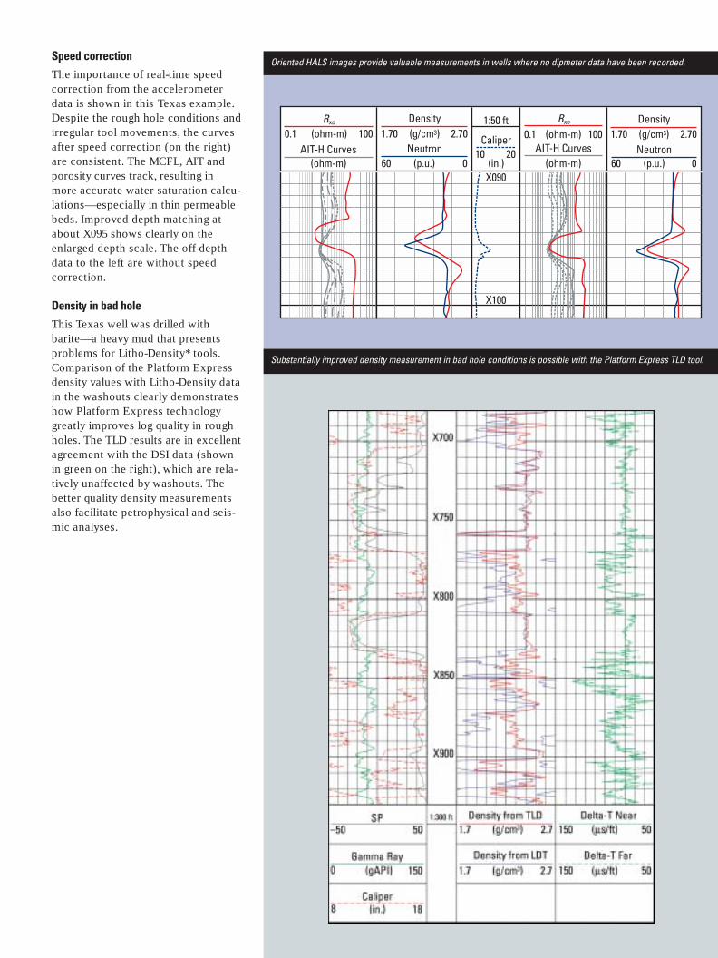
Oriented HALS images provide valuable measurements in wells where no dipmeter data have been recorded.

Permeable zonesThis Texas example shows the 2-ft ver-tical resolution curves with five depthsof investigation across several perme-able zones. The Platform Express mudresistivity measurement is used for
real-time environmental corrections.The MCFL log is plotted to confirmthe AIT readings, and the resistivitystandoff—another exclusive mea-surement of the Platform Expresssystem—is computed from the MCFL.
HMIN and HMNO are the two micro-log curves computed from the MCFLdata. The red shading indicates thickmudcake over these highly permeablezones.
Platform Express system accurately and quickly measures resistivity and shows permeable zones.

X705
X710
X715
X725
X730
X735
X740
X720
1:150(m)
High-Resolution Laterolog Deep (HRLD)
0.02 (ohm-m) 2000
0.02 (ohm-m) 2000High-Resolution Laterolog Shallow (HRLS)
ShallowImage
DeepImage
HALS images bring greater precision to bedding analysis.
HALS resistivityThe ability to plot both shallow anddeep high-resolution azimuthal imagesis another unique Platform Expressfeature. In this log, recorded in a test
well in France in combination with aninclinometer tool, the pad orientationcurves appear in the image tracks.Dip estimates can be made where thetool face orientation and hole deviationand azimuth are known.

MCFL measurements correlate well with FMI images for the identification and characterization of thin beds.
MCFL with FMI imageOverlay of the MCFL curve with theborehole image derived from the FMI*Fullbore Formation MicroImager con-firms the high vertical resolution ofPlatform Express data. Conductivityvariation in the zone between X652
and X655 m in this Argentina well is visible on both the MCFL data and the FMI image.
Core photograph comparisonThe high-resolution data obtained bythe Platform Express tool can be usedto identify impermeable laminationsin the formation that can act as flowbarriers to production. In this well,there was concern about the continuity

Depth(1:20 ft) St
anda
rd C
ore
Phot
ogra
ph
Ultra
viol
et-L
ight
Co
re P
hoto
grap
h
2-in. Resistivity
1 (ohm-m) 100
XX34
XX35
XX32
XX33
XX36
XX37
XX38
XX39
XX40
XX41
XX42
XX43
Caliper (HCAL)
6 16
1-ft Resistivity
1 (ohm-m) 100
1-ft Resistivity
1 (ohm-m) 100
18-in. Resistivity
1 (ohm-m) 100
Gamma Ray (HGR)
0 (gAPI) 150
60 (p.u.) 0
Neutron Porosity (HNPO)
2 (2-in.) 7
Photoelectric Factor (PEFI )
1.65 (g/cm3) 2.65
TDL 2-in. Density(RHOI)
Detailed comparison to core photographs confirms the resolution of the Platform Express system.
of limestone streaks in the formation,which would help contain water belowthe reservoir section and enhance thesteamflood of the reservoir. The coredata are not definitive: only limestonecobbles were recovered, and they couldrepresent either the nature of thedeposition (nonbarrier cobble layer)
or the nature of the coring operation(the coring process created roundedfragments of a thin layer). However,the consistent response of the TLDand MCFL to these thin layers revealedthe continuity of the laminations, andthe operator was able to complete thezone closer to the known water contact
of the reservoir with no additionalwater cut.
The high-resolution (2-in.) densityand photoelectric factor measurementsclearly resolve the carbonate layersand, with the addition of the 2-in. resolution R
xofrom the MCFL, also
identify thin oil-bearing layers.

Well Trajectory
Depth1:1000
(m)
Resistivity
Porosity
The real-time display of Platform Express data is easily customized.
Customized answersThe integrated z-axis accelerometer inthe Platform Express system enablesspeed correction of all data and deter-mination of the wellbore deviation,which is used to compute true verticaldepth (TVD) logs and plot the well-bore position of highly deviated andhorizontal wells. This customized plotcombines the measured-depth datawith a horizontal depth coordinatesystem originating at the bottom ofthe well. The color-coded bar next tothe depth track indicates the directionof the well relative to horizontal (90°deviation)—green to black where
descending and red to orange whereclimbing in angle. Displaying the com-puted lithology color plot on the welltrajectory is ideal for showing notonly the position of a horizontal wellbut also its attitude in reference tointersected lithologic features.
In this example, the well penetratedsalt and anhydrite layers out of casingand entered the sand reservoir. After75 m in the sand, the well entered ananhydrite layer and then went backinto a sand. Were there two anhydritelayers or one displaced by a fault?Or did the well turn up and reenterthe anhydrite layer above the reservoir?
The well trajectory plot clearlyshows the well turning up before itenters the anhydrite layer. A line drawnalong the sand/anhydrite contact indi-cates that the boundary has a uniformstructural dip along the section, whicheffectively eliminates the possibilityof a second anhydrite bed and thefault theory. The well simply reenteredthe caprock anhydrite and then wentback into the sand reservoir. Withoutthe Platform Express well deviationdata, this analysis would have beendelayed until other well deviation datacould be correlated to the log data toexplain the lithology changes.
X090
X100
Rxo
0.1 (ohm-m) 100AIT-H Curves
Density1.70 (g/cm3) 2.70
Neutron60 (p.u.) 0
1:50 ft
Caliper10 20
(in.)
Rxo
0.1 (ohm-m) 100AIT-H Curves
Density1.70 (g/cm3) 2.70
Neutron60 (p.u.) 0(ohm-m) (ohm-m)
Oriented HALS images provide valuable measurements in wells where no dipmeter data have been recorded.Speed correctionThe importance of real-time speedcorrection from the accelerometerdata is shown in this Texas example.Despite the rough hole conditions andirregular tool movements, the curvesafter speed correction (on the right)are consistent. The MCFL, AIT andporosity curves track, resulting in more accurate water saturation calcu-lations—especially in thin permeablebeds. Improved depth matching atabout X095 shows clearly on theenlarged depth scale. The off-depthdata to the left are without speed correction.
Density in bad holeThis Texas well was drilled with barite—a heavy mud that presentsproblems for Litho-Density* tools.Comparison of the Platform Expressdensity values with Litho-Density datain the washouts clearly demonstrateshow Platform Express technologygreatly improves log quality in roughholes. The TLD results are in excellentagreement with the DSI data (shownin green on the right), which are rela-tively unaffected by washouts. Thebetter quality density measurementsalso facilitate petrophysical and seis-mic analyses.
Substantially improved density measurement in bad hole conditions is possible with the Platform Express TLD tool.

Specifications
Length 38 ftWeight 690 lbmMax OD 33⁄8 inMin OD 45⁄8 inTemperature rating 260°FPressure rating 10,000 psiHole size 6 to 16 in.Max logging speed 3600 ft/hr
HGNSHighly IntegratedGamma RayNeutron Sonde
Electronicscartridge
HRMSHigh-ResolutionMechanicalSonde
HALSHigh-ResolutionAzimuthalLaterologSonde
AITArray InductionImager Tool
38 ft
Platform Express revolutionary reengineering of wireline logging is only38 ft long and weighs 600 lbm.

SMP-5177 ©Schlumberger
September 2001 *Mark of Schlumberger
www.connect.slb.com