jorma rytkonen rakenteiden mekaniikka vol. 22 no...
TRANSCRIPT

EXPERIMENTAL INVESTIGATION OF THE PLUNGER TYPE WAVE MAKER
Jorma Rytkonen
Goran Granholm
Rakenteiden mekaniikka Vol. 22 No 3 1989 s. 25 ... 46
SUMMARY: This article describes the preliminary model test r esults of a plunger type wave maker conducted at the Ship Laboratory of the Technical Research Centre of Finland. The main goal of the r esearch project was two-fold: First to study the wave making characteristics in a 130 m long towing tank with an aid of model techniques. Second to design a new wave-making device and effective absorbing dampening construction for a 40x40 m2 wide testing basin.
INTRODUCTION
This paper presents the preliminary model test results of a
plunger- type wave maker. The main aim of the study was to
find out the main characteristics of an oscillating body
having a triangle shaped cross- section . The tests included
the measurements of the wave amplitudes for various wave
maker strokes. In order to study the hydrodynamic forces
acting on the body and the hydraulic actuator dimensions
needed, the total force required to move the body was
measured, too.
The wave maker study described in this paper was one part of
the project to design a new wave maker for a 40 x 40 m2 wide
ice tank ( former manoeuvring basin ) , thus enabling open
water testing with or without drifting ice in waves. In the
first phase, however, the main characteristics of
25

'laboratory waves' were studied by modelling the existing
towing tank wave maker in the scale of 1 to 5. An other
pur pose was also to study the possibility to renew later the
towing tank wave maker to achieve higher wave amplitudes.
Three different body cross-sections were tested using the
wave angular frequency range of 1 .. 8 radj s in full scale ie.
in the towing tank conditions. To avoid any reflections
during t h e testing phase the duration of single measurement
was a rranged s o t h at any secondary distortions could not
distur b t he measurement. This was achieved by having short
measuring per iod in respect t o t he travelling time of the
reflected wave f r om the end of the fl ow flume. All tests
were carried out by u s ing regular waves.
This work has been carried out in a co- operation with the
Hydraulics Laboratory of the Helsinki University of
Technology, which has offered the flow flume for the
measur ements. The developed model wave maker with the
PC- microcomputer based control unit enables now, after this
towing tank study, basic 2- dimensional hydrodynamic testing
in a flow flume. Thus various coastal engineering problems
like the stability of breakwaters etc . can be studied using
suitable scaling dimensions .
THEORY OF A PLUNGER TYPE WAVEMAKER.
In laboratory test tanks, water surface waves are created by
causing a forced oscillation of the water particles at one
end of the tank. In most cases, this is done mechanically
with different kinds of waveboards and plungers. One major
princ iple in wavemaker design is to try to get the fo r ced
oscillation to match the nat ural water particle oscillation
in a wave as well a s poss ible. Us ua lly wavemakers work
satisfactorily at a limited, specific frequency range . At
frequencies outside this range, horizontal accelerations at
the wavemaker surface at variou s depths are inadequate,
causing distortion o f t he wave shape.
26
The majority of wavemaker theories concern piston- or
flap-type wavemakers /4/. Especially studies on vertically
oscillating plungers seem rare. Besides there may be lesser
need for theories of this kind one reason has been the
difficulty to present a theory that would in some manner
cover the variety of plunger shapes in use. Actually it has
proved difficult even to find an analytical solution of the
generated wave for a body of any shape. Ursell /9/, however,
has analyzed waves generated by an oscillating circular
cylinder and found that the generated wave height only
depends on a dimensionless parameter kr, k being the wave
number and r the radius. Wang /10/ used a similar reasoning
when extending the theory to plungers of more o r less
triangular shape, using Lewi's conformal transformation. In
Wang's study a two parameter transformation was used that
does not yield exactly the triangular shapes intended.
Wang, too, found that the wave height only depended on the
dimensionless parameter kd, where d is the breadth of the
plunger at the water surface. The plunger geometry, Wang
described by two parameters; the sectional area coefficient
and the breadth at the water surface .
For prismatic plunger Galvin /3/ found an approximative
solution for the wave generators in shallow water. He stated
that the height of waves generated by displacement type wave
generators equals approximately to 2nSIL times an appropri
ate dimension of the wave generator. The terms S and L are
the stroke of the wave generator and the wave length,
respectively. His assumptions, however, are valid for the
ratio of water depth and wave length beeing less than 0.05 .
Wu /11/ , unlike Wang, took into account the effect of water
depth. He used the boundary collocation method to solve the
Laplace equation together with the combined free surface
boundary condition, the kinematic boundary condition at the
wavemaker and the bottom boundary condition. In this method
27

the test channel is divided horizontally into a number of
segments each containing one node point at each end. The
nodes on the plunger side of the channel are required to
satisfy an equation formed of the Laplace equation and the
boundary conditions. The unknowns in this equation are found
by simultaneously solving the linear combination of
functions for the segments in the sense of the least square.
In the following the wave maker dynamics is described with
an aid of the similarity of forced and dampened
spring- mass- system (Fig. 1) . However, only the basic
equation of motion and some essential parameters are shown.
The more detailed discussion of the body motion dynamics is
presented in refs./2/ and /7/.
K
Kx Cx
Fasinwt
Fig. 1. The spring mass system.
The dynamics of a plunging type wave maker can be described
by a dampened spring- mass system with a single degree of
freedom in the direction of the imposed harmonic external
force. According to Fig.l we can consider a system with a
mass, m and a spring constant, K. The mass is moved by an
28

external force of amplitude F0 , and it is linearly damped
with a damping coefficient, c. Assuming further the angular
frequency of linear vertical movement beeing, w, the
equation of motion thus consists of an inertia force, a
damping force and a restoring force term all resisting the
external force. Thus the equation of motion can be described
as
mx+Cx+Kx=Fosinwt ( 1 )
In above equation the mass term includes both the mass of
the body and the added mass . The added mass is the mass of
water which when accelerated would produce an inertia force
equal to the vertical resultant of all fluid pressures
caused by the actual acceleration of water particles
relative to the body.
The steady-state oscillation is generally represented by the
following equation:
x=Xsin(wt-a) ( 2 )
where X is the amplitude of oscillation and the angle (wt-a)
is the phase angle. Term a is the lagging phase angle
between the motion and the external force.
Differentiating x in above equation with respect to time and
substituting in eq. 1. v1e get:
-mw 2 X(wt- a)+ CwX cos(wt- a)+ K Xsin(wt- a)= F 0
Sin wt ( 3 )
The coefficients of sinwt and coswt can be assumed to be zero
(orthogonal to each other). Thus we get from eq. 3:
-mw 2 X cos a+ CwXsin a+ KX cos a= Fa ( 4 )
29

mw 2 X sin a+ CwXcosa- KXs in a = 0 ( 5 )
Solving X and a the following formula presents the
amplitude of oscillation and the phase angle of motion /2/:
( 6 )
w tana=C
2 K-mw ( 7 )
From the general force - deflection equation o f a spring- mass
system,
F=KX S ( 8 )
we get for the deflection, X,=F.IX. So the magnification
factor, X/Xs can be written as:
X ( 9 ) X s
For the phase angle we get :
2l;( ~) tan a= ( w ) 2
1- -w.
( 10 )
where
( 11 )
is the natural frequency of the system and
30

t;=C/Cc ( 12 )
is the damping factor which states the ratio of the
dampening to its critical damping value, Cc (-2!Km).
Th e s olutions of equations above are shown graphically in
Fi g. 2 f or o:::; ?;":::; 1.0, where all curves approach t he static
deflect ion at very low frequencies . At higher frequencies
the d ampening effect is negligible but near the natural
per iod , i e. n ear the resonance point the damping has a
pro f ound e f fect on the deflection .
tr 0 ,_ u l1. 2.0
z Q ,_ <t 'd u. 1.0 z (!) <t ~
0
..,I. ............
180'
1). ,.--- o j
0.05 IJJ ~ 0~ ~ O.IC
0.15
0.25
if ~5 ~ 1\' ~\
"--I~ ........._
1.0
....1
~9 (!)
~ 90 -/; IJJ
r .£ "' /dJ <t Cc :X:
a. 0 I 2
FREQUENCY
~ ~ .....
2 .0 3.0
FREQUENCY RATIO ~ Wn
3
RAT IO
4 .0
4 5 ~ Wn
5.0
Fig. 2. Solutions for a forced linear spring- mass system
/2/.
TEST PROCEDURE
The tov1ing_ tank wave maker
The towing tank wave maker consists a wedge-shaped plunger
which oscillates through a lever arm as shown in Fig. 3.
31
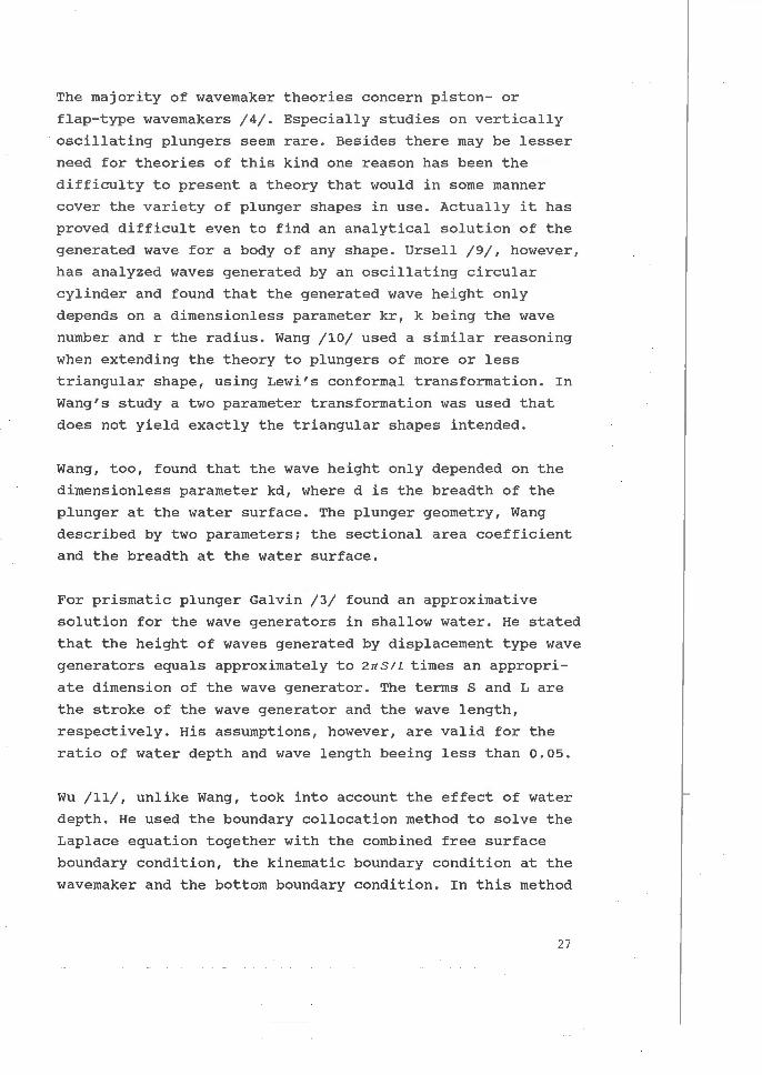
Fig. 3. A schematic representation of a towing tank wave
maker.
The wave maker is powered by an electro- hydraulic servo
actuator system which consists of a hydraulic cylinder for
motion, dampening cylinders and pressure accumulators. The
length of the lever arm is 2.5 m thus the radius of the
oscillation line is 2.5 m round the bearing point.
The cross- section of an oscillating wedge is theoretically a
triangle when the plunger is assumed to oscillate only
vertically without any rotation. The existing body form has
been derived from a triangle by obtaining the angular
movement round the bearing point. So the basic wave maker
theories developed by Biesel, Havelock and Ursell /1/, /9/
have been used when estimating the ratio of wave amplitude
achieved and the stroke of the body.
The angular frequency range of the existing wave maker is
abt. 1 .. 8 radjs. The maximum wave height observed is abt.
0.3 m which could be seen from Appendix 1. The data of
Appendix 1 include also the model test results. The original
32

full scale data are on the right hand side column of the
appendix 1. These full scale data are based on the
calibration measurements carried out after the installation
of the existing towing tank wave maker .
Selected test criteria
Two basic goals were set for t he t ests : First t o try to
achieve a maximum f ull scale wave height of 0 .5 m. Secondly
to increase the wave heights especially in the case of l ong
waves hav i ng angular frequency o f 1 .. 2 radjs. The linearity
of waves and the wave asymmetries were also studied . Thus
the demand of 5 % for second order harmonic s ine wave
a mplitude ratio was set.
In order to verify the performance of the model, the test
was carried out as a scale model of a previously run full
s cale calibration test of the actual wave maker . Thus the
distances from the wave maker to the three wave gauges
c orresponded to the distances in the calibration test. Also
the same stroke amplitudes and angular frequencies were
used, and one of the plunging bodies was made as a scale
model of the original plunger.
As the width of the channel was not scaled, it was found
most accurate to make the comparisons using the wave gauge
closest to the wavemaker. The main reason for this was
disturbances caused by friction of the channel walls. The
friction caused an oblique cross- waves to develop especially
with short waves, which in the case of very steep waves
resulted a wave breaking in the node points of progressing
wave crests and oblique disturbances .
Also the wave height records of the full scale test appeared
more reasonable at the first wave gauge, because some of the
measurements further away may have been affected by
reflections.
33

The model tests were conducted in the scale 1 to 5 in the
glass walled flow flume of the Hydraulics Laboratory of
Helsinki University of Technology . The cross- section of the
flume is 1.1 x 1.3 m2 and its effective length is 55 m.
Figure 4 shows the measuring principle of the test
facilities. The dimensions of plunger shapes tested are
shown in table 1.
Table 1. The full scale dimensions of plunger- cross- sections
tested.
Wedge d
[m)
A (original) 1. 63
B
c 1. 70
1. 60
b
[m]
0.975
1.10
1.10
.-----1 COMPUTERj....,.--lWAVE DATAj
+ Force lronsduc er t .-------'------, Wove gouges
CD @&0)
f) • Servovolve
55.0 m
Fig. 4. The measuring principle.
34
! S,sinwt
b - ===---
...

The wave maker was controlled by PC/AT-microcomputer, which
was equipped with AD/DA-converter thus enabling both the
controlling and measuring phases. The waves were recorded in
sequenses of ten or fifteen seconds, each record consisting
of 1024 measuring points. Depending on frequency, the waves
were thus described by 35 .. 191 points each .
The time history of the plunger motion was recorded using
the same sampling frequency. In these tests the stroke
ampli t ude is defined as a half the length of the arc
described by a point on the back side of the plunger during
one complete cycle of oscillation.
The force required to move the wedge up and down was
measured by a force transducer. The transducer was connected
between the wedge and the hydraulic actuator, thus the
measured forces represent the values of t o t al forces. The
measurements of forces will not be discussed in this paper,
but published later in the VTT- Research Notes.
RESULTS
Wave heights.
From each record, the gained wave height was calculated as
the arithmetic mean of a number of successive zero
downcrossing waves, defined in accordance with the
IAHR- recommendation /5/.
The recorded wave heights, transformed to full scale, are
presented in Appendix 1, together with the original full
scale wave recordings . It appear s, that the wave heights in
the model tests with the original plunger shape match the
full scale measurements reasonably well especially on
frequencies below 6 radjs. It is therefore believed that
also other plunger geometries perform in accordance with
Froude's model law, and that additional scale effects are
negligible.
35

The modified plungers, B and c, seem to produce considerably
greater wave heights . Fig . 5 shows amplitude/stroke ratios
plotted against frequency, which is made dimensionless as
kb. Amplitudes are taken to be half the wave height. The
plotted co- ordinates are connected with analytically
determined best fit lines of a power function, in order to
visualize differences . Thus, it is not claimed that these
curves would represent an approximation of the amplitude
ratios at different frequencies . This is also due to the
fact that the shape of any best fit curve depends on the
number of measurements and the choice of str oke amplitudes
at each frequency . However, a clear tendency can be seen .
Plungers B and c give a wave height about 40 percent greater
than the original plunger shape A.
1.5
Cll 1.0 .......... 0
0.5
0 . 0 +..,-..---.--,---r---r--r-r-r--,--r--r-,-,--,--..-..,-........,---,
0.0 1.0 2.0
kb 3.0 4.0
Fig. 5. Wave amplitude to stroke ratios with three different
plunger shapes.
Regularity of a wavetrain.
As a measure of the grade of regularity of the wavetrain,
the standard deviation of the determined wave heights was
36

calculated from each wave record. The percentage of
deviation from mean wave height at different frequencies is
shown in Fig. 6. In all cases, a relatively great deviation
can be noted at small wave heights. This is caused by the
adhesion effect between the water and the glass side walls,
that creates small diagonal waves interfering with the
actual generated waves. Because it cannot be concluded that
these disturbances exist in the actual wave tank, less
attention should be paid to these values.
0.0
~ vs.o
.; ~•.o
·~ ,2,0
·~ ~o.oa-l:-.o~""o.'7"o ~o"".z,..-""'o'"".J-..,.0 . .,..4 -""o.•,..-""'•""·•-""o.7
'NOVO height (m)
0.0
0.0
c . UIS.Q
.2"·0 1 "02.0 . ~ •. o •. lz.o-..,.o.'7", -::-<~:-"G<\::::...,:,.,.J~:~;..,.~.,..4 -ai~o~i-.P~o,..,..~~.,. •.. ,
wove height (m)
0.0
c . ue.o
&4.0
~ ·~ ,,_o . ·~
"!o.ool,..o-.,..o."'o -o"".z,.........,o,.,..J-..,0.~4 -o"".•,......""'o"".•~""o.7 wove hl!light (m)
Fig. 6. Percentage of standard deviation of recorded wave
height at different frequencies. a) 2 radjs, b) 3 radjs, c)
4 radjs and d) 5 radjs.
At greater wave heights, a sharp bend upwards occurs, which
can be interpreted as the breaking point. At angular
frequencies of 3 radjs and less, breaking waves did not
occur.
37

For all of the plungers 3 radjs seemed to be the optimal
working frequency in the sense of wave regularity. This vms
also the frequency at which the greatest waves were
recorded.
Wave shape
Although the oscillation of the plunger can be considered
strictly sinusoidal, the formed wave differs in shape from a
pure sine wave. As most wave theories still assume
sinusoidal waves or an irregular seastate composed of sine
formed waves, attempts are made to create such waves or at
least to know how much the created waves differ from sine
waves. Figure 7 shows a recorded wave compared with a sine
of the same wave length and the same height.
0.08 ":!
l ·"" 0.04 j '/~ -''\ 0.02 l .:! ' \
! 0.00 fl /,/ ·~ ' Lo2 \ ,/ '\ ./ ' ~ ~~;/ ~/
-004 ', ... _,' ',_ ... /
-006]
-o 0~.+-c.O~~o.""lo~"~o.""lo~"'T""~o""6o~~o""'8b~~,.,...bo .......... ~, .~2o~~,..,,.,.,, ~ .. ,.,.,, ~, so time i'e:)
Fig. 7. Recorded wave compared to pure sinusoidal wave.
Plunger C. w=3radls, second harmonic ratio is 17.3 %.
For a more analytical approach the wave records were
Fourier-analysed and dissolved into a series of harmonic
sines. The ratio of the amplitudes of the main wave and its
second harmonic was taken as a measure. Figure 8 show this
ratio plotted against wave height for the different plungers
at different frequencies. In the case of plunger A the ratio
is clearly more dependent on the frequency than in the case
38

of plungers B and c. The results of B and C are considerably
similar to each other, although model C behaves slightly
better at high frequencies .
20.0 A 0 :z. ro.A js ]
0 a J 'o t5.0
.e. D. 4 .2 ] to.o <> s ~ -'= 5.0
0.2 O.l 0.4 0.5 0.8 0. wove height (m)
_20.0 _ 20.0
~ ! ~ ~ 1!1.0 "Q-1!1.0 ;f( c .e. .e.
:8 s · ~10.0 ~10.0
~ e ~
~ ~0 .c: 5.0
" ..,
c c
~ 0 u
" 0.0 0.1 0.2 O.J 0.4 M 0.8 o. g o.ol).ll 0.1 0.£ 0.0 wav~.Jheigh~ .... (m)'5 0.8 0.7 wove height (m)
Fig. 8. Ratio.of second to first harmonic sine wave
amplitudes (per cent) .
The wave shapes were further examined by determining the
horizontal and vertical asymmetries as defined in Figure 9.
A horizontal asymmetry greater than 0.5 indicates a sharp
crested wave with a flat trough. In the sense of horizontal
asymmetry plungers B and C again seem to perform equally
well, while waves produced with plunger A are somewhat less
asymmetric. The plots resemble very much those of the second
harmonic wave amplitude ratios.
39

~f~S"'l"El1:l'IIIOSS. s~. "' .. /L C::~ R.EM. S"!EOP\.aii!.l" s~ , A .. /J.: 'l lii!.TICA\,. A-SVI-I"E'Tlt-"f /" v = t::. /1-' ltoll.IUlto'i~ .tS rHHEfl~~
~1'1 . Ac.j'r't
Fig . 9. Wave asymmetry parameters .
Vertical asymmetry is a measure to compare front and rear
crest steepnesses. A value of more than 1.0 means that the
front of the wave is steeper than the rear. Surpr isingly,
plunger B seems to create very asymmetric waves at
frequencies 2 and 3 radjs. At 3 radjs the asymmetry occurs
when the wave height exceeds 0 .5 metres, but at 2 radjs also
the smallest waves have an asymmetry of about 1.2 and it
increases fast with increased wave height. This is explained
by the sharp angle which the plunger's front side forms with
the water surface. The forced acceleration of water
particles is greater than the natural acceleration on the
surface of these long waves . The characteristics of A and C
are much more stable, keeping for mostly within the limits
0 .8 .. 1.2. The average vertical asymmetry of waves made with
plunger B is, however, clearly greater than 1.0, while in
the case of A it is somewhat less than 1.0.
Comparison of measured and theoretical wave heights
In this study, the measured amplitude/stroke ratios were
compared with calculated results according to Wang's theory
40

/10/. The sectional area coefficient, a is described as the
ratio between the cross section area and the product of the
breadth and height of the cross section:
A=a·b·d ( 13 )
Because the plungers here were hinged at a pivot point and
oscillated not vertically as in Wang's theory, the sectional
area coefficient was determined considering the distribution
of horizontal displacements, rather than the shape of the
plunger itself. Using this assumption, plunger A has a
sectional area coefficient very close to 0 .5. For plungers B
and C the coefficients are more difficult to determine, as
they are not constant with depth, which is assumed in
theory.
The wave amplitude/stroke ratios of plunger A is plotted in
Fig. 10 together with Wang's theoretical values correspon
ding to triangular plungers of d/b ratios of 1.5 and 2.0 and
a sectional area coefficient of 0 .5. The measured values fit
between these two curves at all frequencies. From the
geometry, the corresponding djb- value of plunger A can be
estimated to be about 1.7.
'" j ~ 1.00 ~
c ~ 0.50 1
1 l
0.00 +,---r--,--,r-r-r-t'-r--:-r--r-;c-r-,-,, --r-T""T"~ :.oo 2.00 J.OO .!.CO
kC
Fig. 10. A comparison between measured and theoretical
a;s-ratios, Plunger A (Wang, a= 0.5) .
41

The ajs ratios of plungers B and c, were compared with the
plungers having sectional area coefficients 0.4 (Fig. 11 ) .
Both B and C produce proportionally greater waves than the
theoretical curves indicate. From the geometry it is clear
that these plungers cannot be compared with the theoretical,
horizontally moving plungers with constant sectional area
coefficients.
1.50
Ul 1.00 ......_ 0
o.so
plunger B
0.00 + ,.....,.....,....,,_,...T""T"'T"",.....,.....,....,-,-.,.,-.,.-.-.-,--, 0.00 1.00 2.00 3.00 • .CG
kb 1.00 2.00
kb
plunger c
3.00 • . 00
Fig. 11. A comparison between measured and theoretical
a j s-ratios (Wang, a=0.4).
Force requirements
In order to evaluate the force needed to drive the plungers,
an attempt was made to determine their added masses and
damping coefficients. The damping was assumed linear. The
test was done as a zero-force test by disconnecting the
power unit from the wavemaker and letting the plungers swing
freely on the water surface. The dampened oscillation of the
plungers was recorded. The mass of the oscillating part of
the wavemaker was measured in each case, and its mass centre
was determined. For simplicity, also the spring coefficient,
k, was taken to be constant, although it is evident from the
geometry that especially for plungers B and C this is not
true. The spring constant was thus described as
42

( 14 )
where Aw is the water plane area of the plunger at mean
water level. With these assumptions made, the following
values of coefficients a, c and k were obtained:
Table 2. Added mass, a; damping coefficient, c; and spring
constant, k for the different plunger shapes.
plunger
type
a [kgjm)
[kg)
c [kgjsjm)
[kgjs)
k [kgjs*s/m]
[kg/s*s)
CONCLUSIONS
A
497 . 7
5474.7
1421.3
15634.3
9406.0
103466.0
B c
562.5 398.1
6187.5 4379.6
1825.1 2459.7
20075.0 27056.4
10890.0 11138.4
119789.0 122522.7
The plunger type wave maker characteristics were studied
experimentally. The effect of a plunger cross-sectional
shape on generated waves was studied using three model wedge
cross-sections in the scale of 1 to 5.
The modified plungers, B and c, seemed to produce
considerably higher waves compared to the original body form
A. The wave heights greated were approximately 4 0 % higher
with the plungers B and c. The wave horizontal asymmetries,
however, were greater for the plungers B and C.
The analyzed values of vertical asymmetries showed plungers
A and C beeing quite stable in a sense of the linear wave
shape and the regularity of the wave train. Plunger C
43

created very asymmetric waves at the frequency range 2 to 3
radjs. For all the plungers tested the frequency of 3 radjs
was the optimal working frequency when the highest waves
were observed. Thus the waves generated by plunger B were
out of the design limits in the sense of the linear and
'pure' wave formation.
REFERENCES
/1/ Bullock, G. & Muiton, G. , Performance of a Wedge- type
Absorbing Wave Maker. Journal of Waterway, Port, Coastal and
Ocean Engineering. Vol 115, no . 1 . 1989 . P . 1- 17.
/2/ Chakrabarti, S. K. , Hydrodynamics of Offshore
Structures . Springer- Verlag, 1987. 440 p.
/3/ Galvin, c., Wave- height prediction for wave generators
in shallow water . Technical memorandum no.4. March 1964, 21
p. U.S.Army Coastal Engineering Research Center.
/4/ Hyun, J. M., Theory for hinged wave makers of finite
draft in water of constant depth . Journal of Hydronautics.
Vol 10, no. 1. P. 2-7, 1976.
/5/ List of sea state parameters(IAHR). Supplement to
bulletin of PIANC- working group, Wave Generation and
Analysis. January 1986.
/6/ Rytkonen, J., Wind waves reflections- A case study.
rakenteiden mekaniikka. Vol.21, no.1. 1988. P. 55 - 65.
/7/ Salonen, E-M., Dynamiikka. Otakustantamo 434, 1980. 458
p.(in finnish).
/8/ Shih, M. c. & Renn, J. c., Hydraulik erzeugt wellen.
dlhydraulik and pneumatik. 32(1988)12. S. 830-832 (in
german).
/9/ Ursell, F., on the heaving motion of a circular
cylinder on the surface of a fluid. J. of Mech. and Applied
Math. Vol II (19 49 )2 . p. 218-230.
/10/ Wang, s., Plunger- Type Wave Makers: Theory and
Experiment. J. of Hydraulic Research, 12(1974)3. P. 357 -
388.
44

/11/ Wu, Y. , Plunger- Type Wave Maker The o r y . J . o f Hydr aulic
Research, 2 6 (1988 ) 4 . P. 483 - 491 .
Jorma Ryt konen, Research Scientis t , Go ran Gr anholm , Research
Tr ainee. Te chnical Re search Centre o f Finl and 1 Ship
Laboratory.
APPENDIX 1 . Average zero downcrossing wave heights
+-----------------------------------+ I Plunger s hape I
+---------+--------+--------+--------+--------+--------+--------+ I ;~~~~ I :;~~~e I I A I B I C I or iginal I +---------+--------+--------+--------+--------+--------+--------+
1 0.147 0.059 0.049 0.148 0 . 038 ? 0 . 201 0 . 067 0.202 0.070 0.205 0.085 * 0 . 331 0.138 0 . 410 0.155 *
---------+--------+--------+--------+--------+--------+--------+ 2 0.042 0 . 047
0.044 0.051 0.045 0.042 0.042 0.048 0 . 063 * 0.064 0.078 0.065 0.077 0.066 0 . 066 0.066 0.070 0.087 * 0 . 129 0 . 152 0.13.2 0.121 0 . 133 0.128 0.134 0 . 1531 0.138 0.172 * 0.179 0.273 0 . 182 0.173 0.209 0.186 0.230 * 0.238 0.220 0 .269 0.240 0.285 * ---------+--------+--------+--------+--------+--------+--------+ 0. 058 0.100
3 0.115 0.240 0.117 0 .202 0.118 0.188 0.240 0.121 0.261 · * 0.155 0.326 0.158 0 . 262 0 . 159 0.252 0.160 0.321 0.161 0.358 * 0 . 228 0.477 0.233 0.369 0.234 0.510 * 0.235 0.468 0.241 - 0 . 2865 0 . 372 0.315 0.651 * 0. 316 0.486 0.653
+---------+--------+--------+--------+--------+--------+--------+
45

46
+--~------+--------+--------+--------+--------+--------+--------+ 4 0.100 *
, 0.0338 0 . 0993 0 . 03 45 0.074 0 . 0346 0 . 07 2 0.105 0.0573 0.160 * 0.058 0 . 128 0.158 0 .159 0.120 0 .117 0 .226 0 .118 0.237 0 .289 0.305 0.133 0.350 * 0.15 3 0 .399 * 0.157 0 .391 0.158 0.301 0 . 457 * 0 .283 0.159 o. 376 0.232 0.466 * 0 .494
---------+--------+---------+--------+--------+--------+--------+ 0 . 045 0.156 *
5 0.046 0 .108 0 .14 0 0 .149 0 .118 0.060 0. 212 * 0 . 06 1 0 .150 0 . 062 0.144 0.191 0. 200 0 . 088 0.285 * 0.090 0.26 4 0 .223 0.091 0 .253 0 . 09 2 0 .184 0 .10 5 0 .3 01 0 .117 0 .314 0.276 0.118 0.232 0.298
---------+--------+--------+--------+--------+--------+--------+ 6 0 . 041 0 .155 *
0 . 0 42 0 . 096 6 0 .159 0 . 053 0 .121 0.196 * 0 . 05 4 0 .198 0.055 0.059 0.063 0.08 3 0.186 0.117 0.140 0.118 0.149
0.165
0 . 175
0.200 0.209
break
0 .113
0 .149
0 .175 ?
+---------+--------+--------+--------+--------+--------+---------+ 7 0.012 0 . 037 0 . 055
0 . 01 3 0.026 0 . 027 0.037 0.038 0.042 0.043 0.045 0 . 050 0 . 051 0.052
0 . 075 0 . 077
0 . 067
0 . 091
0 .116
0.083
0.117 0.11? 0 .129 * 0 .11 * 0 . 121 c
0.11 0.137
0.097
*
0.110
0.11 4
0.118
0 .121
0.04 5 0.072
0.117
0.096
---------+--------+--------+--------+--------+--------+--------+ 8 0.012 ? 0.0607 0.04 5
0.023 0.082 0.024 0.078 0.025 0 . 054 (0 . 06 ? )
0 . 079 * 0.02 6 0 . 099 0.035 0.084 0.086 * 0.112 0 .369 ? 0 . 0376 0.084 0 . 0387 0.08 3
+---------+--------+--------+--------+--------+--------~--------~