journal of metals 1957 - cominto's new sinter plantlibrary.aimehq.org/library/books/journal of...
TRANSCRIPT

Cominco's New Sinter Plant
A lead smelter treating a high proportion of hydrometallurgical zinc plant residues requires specialized technique of feed preparation to incorporate the residues with other feed into a pelletized form for sintering. The design and operation of such a plant at Trail, B. C./ is described.
by E. A. Mitchell, J. F. Melvin, and R. Bainbridge
Fig. 2-lmage from a deformed crystal shows a) bands parallel to the primary slip bands and b) kink bands. Blackening corre
~b sponds to high X-ray intensity. X3.
optical microscopy at this small amount of plastic strain. However, the subsequent application of a
modified phase contrast method confirmed the pl'l'S
ence of kink bands in the positions indicated by the X-ray micrograph. The change in orientation across a kink band is shown by the displacement of the edge of the image at the kink band. This change is of the order of % 0 in this case.
With regard to the lines parallel to the primary slip lines, bands of secondary slip' were observed optically and a count of these gave approximate agreement with the number of lines seen in the X-ray image. The operation of a second slip system would cause these regions to have a slight localized orientation change and thus produce markings in the X-ray images. Using a straig t knife edge as a reference line across the incident beam enabled orientation changes for these lines of up to 27' to be measured.
Acknowledgments The authors thank R. 1. Garrod for his helpful
advice throughout this work and the Chief Scientist, Department of Supply, Australia, for permission to publish this note.
References 1 L. G. Schulz: AIME Trans., 1954, vol. 200, p. 1032; JOURNAL OF
METALS, September 1954. ., A. Kelly and C. T. Wei: AIME Trans., 1955, vol. 203, p. 1041;
JOt;RN'AL Of' l\.1ETALS, Septembel' 1955. :.\ R. W. K. Honeycombe: Jonmal Institute of Metals, 1951-1952,
vol. 80, p. 45.
I N the fall of 1953, The Consolidated Mining and Smelting Co. of Canada Ltd. put into operation a
completely new d modern plant for sintering the rather complex assortment of materials which compris the feed to the Lead Smelter at Trail, British Columbia. This L ad Smelter is one section of an integrat d metallurgical plant producing lead, zinc, silver, gold, cadmium and other metals. Since most of the incoming lead concentrate contains appreci-
E. A. MITCHELL, Member AIME. J. F. MELVIN, and R. BAINBRIDGE, Member AIME, are, respectively, Superintendent, Smelting Dept.; Plant Superintendent, Sintering Plant; and Assistant Superintendent of Development, Smelting and Refining Depts., Metallurgical Div., The Consolidated Mining and Smelting Co. of Canada Ltd., Trail, B. c., Canada.
TP 43930. Manuscript, May 16, 1956. Pacific Northwest Regional Conference, Seattle, May 1956.
TRANSACTIONS AIME
able zinc values, and most of the zinc concentrate similarly contains appreciable lead values, the cross-routing of residues or tails from the respective lead and zinc plants offers obvious advantages in recovery of metals, and has been practiced for many years. A disparity has existed, however, between the output of zinc plant residue and the capacity of the Lead Smelter to treat it, with the result that over the years a stock-pile of residue had been accumulating, and by the end of World War II had reached the formidable total of half a million tons.
To treat this stock-pile, in addition to all current zinc plant residues and, of course, the regular quota of lead concentrates, became a prime objective of the Lead Smelter following World War II. As zinc plant residue plays an important part in the operations to be discussed in this paper, some consideration of its
MARCH 1957, JOURNAL OF METAlS-361

properties is in order. Cominco has two types of this residue to deal with; one from the aciq leaching of the regular zinc calcine (roasted concentrate), and one from the acid leaching of zinc oxide fume pro- duced by retreatment of smelter blast furnace slag. The latter residue is the smaller portion of the cur- rent make, at 120 to 160 dry tons per day and, being rich in lead, is never stocked. In both cases the resi- due is produced as a wet filter cake which is either pumped o r . trammed in V cars to its destination. The calcine leach residue, which is the major por- tion, at about 360 tons per day, contains from 32 to 35 pct moisture as produced. Any which is ponded gradually sets up as it air-dries to about 20 pct moist- ure, forming a fairly firm mass which can be re- claimed with power shovels and trucks. Metal con- tent of the stock-pile material runs about 22 pct Zn and 11 pct Pb.
During the years immediately prior to World War 11, a technique of sinter plant feed preparation had been developed whereby the zinc plant residue was premixed w i t h the dry ingredients of the sinter charge, and the mixture dried to the correct moist- ure content for. sintering. (This step has become known as .the wet-mix step.and the term will be used in this sense in what follows.) A pilot mixing and drying plant had been built, but the installed drying capacity was not adequate to treat the daily output of residue from the zinc operations. The old sinter plant, moreover, dated back to the early nineteen hundreds and was not only inadequate ton- nage-wise but was in very poor mechanical con- dition.
With this background, preliminary study of the problems involved in modernizing and enlarging the . sintering operation was begun. Such factors as the correct integration of the proposed new plant with the other metallurgical operations, space limitations, . .
and the general arrangement of equipment were given careful consideration. It was recognized that the main problems to be faced in designing a new plant were fundamentally mechanical, not metal- lurgical, and involved the handling of large tonnages of material-solid, liquid and gaseous.
After numerous arrangements had been drawn up and studied, a final design was developed which appeared to answer all the requirements. A scale model of the proposed new plant was built and sub- mitted to careful scrutiny before being finally modi- fied and accepted as the approved design, see Fig. 1.
he following sections of this paper will outline some of the more pertinent data which served as a basis of plant design and will discuss plant operation subsequent to erection from both a metallurgical and mechanical standpoint.
Plant Design Production and metallurgy required tha t the new
plant would: 1) Produce 2,000 tons of finished sinter per cal-
endar day containing up to 500 tons of lead. Treat- ment rates.were based on a 110-hr week.
2) Treat all current zinc plant residue and permit the reclamation of up to 250 tons per calendar day of stock-pile residues.
3) Roast in two passes, producing a finished sin- ter low in sulfur content and of -suitable physical quality for optimum blast furnace operation.
In addition to .the above, the plant design should be such that: 1) wherever possible, autoinatic in- strumentation would control the process; 2) routine
maintenance would be facilitated to the maximum degree; and 3) a high standard of industrial hygiene would be maintained' through proper dust control and building design.
A plant charge, based on a reasonable forecast of future requirements, was calculated as shown in Table I.
Mixing and Drying-The purpose of the mixing and drying section is to receive the weighed dry in- gredients; 'add a predetermined quantity of wet zinc plant residue; thoroughly mix to assure homogene- ous distribution of the various components, particu-, larly fuel; and dry the mixture to a controlled moist- ure content.
From the basic charge it was calculated that the production of a first pass sinter feed with an average 7 pct moisture content would require the evapora- tion of 283 tons of water per calendar day or 18 tons per hr for a 110-hr week. (It is to be noted that 150 dry tons per day of current zinc plant residue will have been predried to 15 pct HzO in existing dryers
'
and treated as dry ingredients.) Based on recom- mendations of various manufacturers, it was decided that three 10 x 80 ft concurrent-fired rotary dryers, each rated at 6 tons water evaporation per hr, would be installed. By referring to the basic charge again, it will be seen that the average moisture content of the first pass charge would be 18.0 pct. At such a moisture content the mixture would be a slurry and relatively free-flowing. Such a material is not suit- able for efficient rotary dryer performance. Also, during drying, the mixture would pass through an extremely viscous stage which would have the effect of building up dryer crusts, creating a serious oper- ating problem. To minimize this problem and as- sure the maximum dryer efficiency it was decided to recirculate sufficient dryer product to give a net water content of 11.5 to 14 pct, depending on the physical characteristics of the charge. In this moist- ure range it had been determined by test that the feed mixture would be crumbly. It was expected that dryer crusting would be held to a minimum and, with the material showering throughout the whole length of the dryer, fuel efficiency would be high. The material flow is illustrated by flowsheet, see Fig. 2.
In addition to the customary dryer draft indica- tors, a system of recorder-controllers was included in the design for this section of the plant. The pur- pose of this instrumentation was to control auto- matically 1) the rate of flow of pulverized coal to the burners to maintain the required rate of water evaporation, 2) the additions of secondary combus- tion air, and 3) the addition of tempering air to maintain a constant predetermined gas temperature at the dryer inlet.
Sintering-Basically, the sintering operation is one of roasting and, as in most roasting processes, oxi- dation takes place through the proper use of air, with the production of heat.
Experience had shown that an improperly pel- letized and conditioned charge'would tend to pack when layered on a standard sintering machine, throttling the passage of an adequate quantity of air for proper roasting. Although the product from a ' rotary dryer tends to be pelletized, the degree of pelletization can vary over a wide range, depending on such factors as moisture content of the dryer product, the relative proportion of binding material in the charge, and the physical characteristics of the charge components..
362-JOURNAL OF METALS, MARCH 1957 TRANSACTIONS AlME

SUSPENOED CEU.IN6 SINTER
NODULIZEIlS FEEDER
MIXERS 20 TON CRANE
SINTERING MACHINES
SCREENS
L",INo-BOX
SURGE BI IIoIPINGER , FANS SINTER
CRU HER LWIND-8011
BLAST FURNACE FEED 81NS
[COKE STORAGE 81N ST.o RAILWAY CAR
Fig. 1-Photograph of model of new sintering plant, showing general arrangement of equipment. The roof structure with a suspended ceiling is particularly noteworthy.
To minimize variations in the texture of the roaster feed, a p lletizer was provided ahead of each intering machin. These pelletizers were simple
rotating rubber-lined drums, 9 ft diam by 16 ft long. ince the egree of pelletization of any feed mixture
could vary with the peripheral speed of the drum and the retention time, th pelletizers were designed for variable speed and adjustable slope.
Sinter Machine Design, Windbox Area: The grate capacity was determined by experience and test to be 0.21 to of sinter per hI' (net) per sq ft of windbox area on first-pass and 0.095 tons overall. Hence the basic charge tonnage in a nO-hI' week would require 554 sq ft of windbox grate area for first pass and 787 for econd.
After weighing the merits and disadvantages of few large machine vs numerous small machines, the decision was for the former. Three machines 10 ft wide were fin lly chos n, each with 630 sq ft of windbox area one f which could act as spare for either first or second-ov .
Fan Equipm nt: Test data and plant experience had shown that the requisite air volume for satisfactory sintering was: 1) for first pass, 65 dm (stp) per q ft of windbox area at the grates or, allowing 25 pct leakage, 81 cfm (stp) at the fan, and 2) for second pass, 90 cfm (stp) per sq ft of windbox area or 113 cfm (stp) at the fan.
To determine true volumes at operating conditions which would erve as a basis for fan design, average plant data were utilized. These are illustrated graphically in Fig. 3. This graph portrays air volume, the percentage of SO., and the gas temperature prevailing as roasting proceeds. It will be noted that gas temperatures are high and S02 concentrations relatively low toward the end of the roasting time indicated. It was recognized that, ideally, a series of f ns should be installed along the length
TRANSACTIONS AIME
of each machine, each being controlled separately through a series of windboxes. This was deemed impractical. As a compromise it was decided to divid~
the windbox area into six equal sections and install two fans, one handling the rich gas from the first four windboxes and the second, the gases from the last two. This arrangement would make it possible, if it were required at some future date, to recirculate the weaker gas and so produce a gas of higher SO" concentration.
Based on predicted gas temperatures and volumes, and in consultation with fan manufacturers, fan specifications were drawn up as in Table II.
For the preliminary design, fan speed control through the fluid drive would be based on draft at the fan inlets. Since the gas would be relatively wet (dew point estimated at 135°F), and of relatively high SO. content, all fan casings and windbox ducts would be of mild steel construction, but heavily insulated. Fan runners would be stainless steel.
No attempt was made at this time to design a new flue and humidification equipment to condition the gas for dust recovery in the existing Cottrell precipitator. The old flue system would be used until such time as gas data were confirmed by operation.
Sinter Machine Design, General: Generally speaking, the machine design followed the normal DwightLloyd (straight-line) pattern. However, certain modifications were incorporated. Because of the size, it was decided that the loaded pallets, when discharging, should not be allowed to run free from the top. A discharge sprocket, controlled by a brake, w s provided at the discharge end of the machine to release the loaded pallets at the bottom. This would permit a bump adequate to remove the sinter cake without damaging impact.
Another feature of the sintering machine design worthy of note is the method of removing windbox
MARCH 1957, JOURNAL OF METAl5-363

3 WAY SPLITTER S.R L PUMP
TO NO2 MIXER TO N 0 . 3 MIXER I N D DRYER AND DRYER
TO LO 2 DRYER
TO SINTERING
Underflow WATER
Atmosphrre
Fig. 2-Schematic flow sheet of mixing and drying.
cleanings. Those familiar with a lead-bearing charge know the problem involved in removing metallic lead from a dry windbox. A wet windbox will pro- duce a granulated product but its removal from six .I0 x 10 ft windboxes presented a challenge. The final design included a continuous 9 ft 7 in. wide rubber belt conveyor. This belt ran within the water windboxes and close to the bottom, discharging any cleanings into a boot at the end of the machine. An inclined drag conveyor was provided to remove this material continuously from the boot. A general ar- rangement of the new machine is illustrated. in Fig. 4. A flowsheet of the sintering section is shown in Fig. 5.
Instrumentation: In the sintering process, there are certain key data which, properly interpreted, will indicate such factors as degree and rate of roasting, gas volumes and, indirectly, physical qual- ity of final sinter. A centrally located control room was designed from which all the plant, with the exception of the sinter crushing section, is visible. All control instruments and recorders were located in this room. Eacl-i sintering machine had its own instrument panel. Instruments included in the de- sign were: 1) SO, recorders on each fan, 2) draft recorders on each fan, 3) indicating ammeters on each fan motor, 4) six point temperature recorders on each machine to show individual windbox tem- peratures, and 5) machine speed indicators with push-button control.
In addition to the above, recording instruments were provided for such general information as main flue temperature, draft at certain key locations, SO, ,
concentration at the absorption plant, plant air pres- sure, e t ~ .
Sinter Crushing Plant-In a sintering operation where sulfur is to be removed in two passes the first pass roast must be crushed to as fine a product as is practical without actually pulverizing. This exposes the residual sulfides tied up in the first pass material
and permits further sulfur removal in the second a ~ d final roasting operation.
From basic charge data it is evident that 118 tons per hr of first pass sinter had to be crushed' ex- clusive of any recirculation. Added to this would be some 15 to 20 tons per hr of fines ( - 3 / 4 in. material) screened out of the final sinter and returned to the first-pass sinter conveyors. For the proposed crush- ing plant flow sheet, see Fig. 6.
Allowing a circulating load of 100 to 125 pct the following plant requirements were outlined: 1) two sets of 54 x 24 in. smooth rolls, operating at 1,250 ft per min; 2) roll drive, 50 hp individual drive for each roll shell; 3) roll setting, 3/16 in.; 4) screening area, not less than 50 sq ft per roll; 5) screen, double deck Ty Rock or other similar type, with throw in direction of flow; 6) screen cloth, standard or medium light Ty-Rod with 0.250 in. opening on bottom deck; 7) theoretical capacity, 72 tons'per hr; 8) screens and rolls to be close-circuited by a pivoted bucket elevator conveyor; 9) to allow for surges and 1:eturn sinter on first pass charge, it was considered that the load to be handled by the pivoted bucket elevator might be as high as 400 tons per hr and, therefore, a 36 x 36 in. conveyor should be installed; and 10) to prevent vibration from the rolls carrying through to other parts of the building, particularly the in- strument control room, the rolls would be mounted on oak blocks on an island free of the main building structure.
General Aspects of Plant Design-A design re- quirement that was given careful consideration and observed wherever possible was ready access to all equipment, particularly the heavy equipment, for maintenance purposes. The main building was de- signed to accommodate a 40-ton crane which would have this access. Equipment was located to provide
Fig. 3-Graphs indicating the normal relationship between percentage of 502, gas temperature, and air volume vs roast- ing time.
364-JOURNAL OF METALS, MARCH 1957 TRANSACTIONS A lME

TO FLUE TO FLUE
Fig. 4-Pictorial diagram of sintering rnochine.
adequate working space. A standard gage railroad track was run into the building so that heavy equip- ment could be transferred to the main repair shops if and when required. Truck access was provided on two levels. Floor space was reserved for a repair shop section where routine maintenance could be handled.
The importance of industrial hygiene was stressed in all phases of the plant design. Lead-bearing dusts and fumes being toxic, all conveyors were hooded, and all points of material transfer were designed to minimize plugging and were ventilated, as was any operating equipment which might produce dust. The application of a wet scrubber* to this service was
The Doyle scrubber, developed by Cominco, available through Dorr-Oliver in the United States and through Power-Gas Canada Ltd. in Canada.
carried through to completion. This equipment, built in several' standard sizes, was installed throughout the plant to collect and recover the ventilated dusts. Building design provided for a suspended roof and for all structural steel to be imbedded in concrete where possible, to avoid ledges on which dust could accumulate.
Another section of the plant was designed to store final sinter, blast furnace coke, and other miscel- laneous materials on blast furnace charge, and to proportion them out as required. However, dis- cussion of this section will not be included here.
Construction of the new plant took place in stages, with the section comprising the sinter machines and crushing equipment in full scale operation by October 1953. The drying and feed preparation.sec- tion, housed in the same building, was completed one year later. I
In general, the plant has proven its potential capa- city of 2,000 tons of sinter per day. Current require- ments of 1,700 tons per day allow for the treatment of a relatively greater proportion of wet residues and for more down time. The somewhat altered feed program from that postulated when the original plant design was worked out has necessitated some changes in the equipment. Comments on these will be included in the remaining portion of the paper. which deals with operation.
Plant Operation A fairly detailed description of the equipment in
the new plant has been published,' and in this paper only as much of this ground will be retraced as is necessary for clarity and continuity in the present account. . .
Proportioning of the concentrates, fluxes, re- claimed dump residues, conditioned flue dusts, fuels and other materials on charge is carried out in the old section of the plant, where reconstruction has not yet started. There are 17 primary charge bins having a total capacity of 26,000 cu ft. .The bins are in line and are accessible only by narrow gage tram- ming. Each bin has two 30 in. discharge feeder belts which are driven through clutches from three sepa- rate line shafts. Bin gates are adjustable and weights checked by a weigh bucket suspended on a monorail. A long conveying system transports this material to the new wet-mix plant. Here a mechanica1;feed splitter proportions the feed evenly to as many of the three dryers as are operating.
Current zinc plant residue at 33 to 35 pct moisture is pumped 1,700 f t from the zinc plant and is re- ceived in .two 100-ton storage tanks. To maintain this residue as a homogeneous slurry, continuous cir- culation is provided by a 3 x 3 in. SRL pump which moves the material from the bottom of the tanks to constant head boxes at the top level of the plant. From these head boxes the required amount of slimes for each dryer is drawn by adjustable-stroke diaphragm pumps, and the excess returns by laun- der to the storage tanks. The heavy (specific gravity 2.1 to 2.3) and viscous nature of the slimes requires close coupling of the diaphragm pumps to the head boxes to maintain the required flow and to achieve reasonably accurate control of delivery. Small dis- charge boxes on each pump allow frequent checking of volume and density.
It has already. been mentioned in considering de- sign requirements that the normal charge of dry materials, when mixed with the planned quota of current residues, would produce a mixture contain- ing some 18 pct moisture. Such a mixture, it was realized, would not be suitable as a feed to the dryers. It would, in drying, pass through a sticky
TRANSACTIONS AlME MARCH 1957, .JOURNAL OF METALS-365
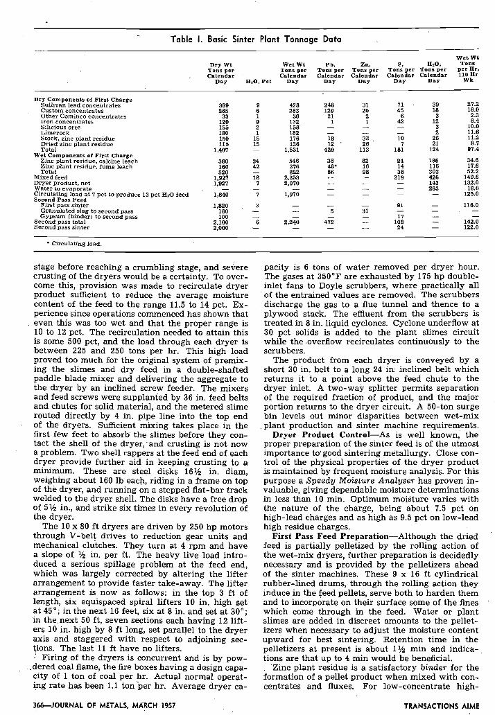
Table I. Basic Sinter Plant Tonnage Data
Dry Wt Tons per
. Calendar
Wet Wt Wet Wt ~ b , Zn, S, HZO, Tons
Tons per Tons per Tons per Tons per Tons per per Hr, Calendar Calendar Calendar Calendar Calendar 110 n r
Day HzO, Pet Day Day Day Day Day Wk
Dry Components of First Charge Sullivan lead concentrates Custom concentrates Other Cominco concentrates Iron concentrates Silicious ores Limerock ~ tock .~ i inc plant residue Dried zinc plant residue Total
Wet Components of Flrst Charge Zinc plant residue, calcine leach Zinc plant residue, fume leach Total ---
Mixed feed 1,927 Dryer product, net 1,927 Water to evaporate - Circulating load at 7 pct to produce 13 pct Hz0 feed 1,840 Second Pass Feed
First pass sinter 1.820 Granulated slag lo second pass 180 Gypsum (binder) to second pass 100
Second pass total 2,100 Second pass sinter 2.000
* Circulating load.
stage before reaching a crumbling stage, and severe crusting of the dryers would be a certainty. To over- come this, provision was made to recirculate dryer product sufficient to reduce the average moisture content of the feed to the range 11.5 to 14 pct. Ex- perience since operations commenced has shown that even this was too wet and that the proper range is 10 to 12 pct. The recirculation needed to attain this is some 500 pct, and the load through each dryer is between 225 and 250 tons per hr. This high load proved too much for the original system of premix- ing the slimes and dry feed in a double-shafted paddle blade mixer and delivering the aggregate to the dryer by an inclined screw feeder. The mixers and feed screws were supplanted by 36 in. feed belts and chutes for solid material, and the metered slime routed directly by 4 in. pipe line into the top end of the dryers. Sufficient mixing takes place in the first few feet to absorb the slimes before they con- tact the shell of the dryer, and crusting is not now a problem. Two shell rappers at the feed end of each dryer provide further aid in keeping crusting to a minimum. These are steel disks 16% in. diam, weighing about 160 lb each, riding in a frame on top of the dryer, and running on a stepped flat-bar track welded to the dryer shell. The disks have a free drop of 5% in., and strike six times in every revolution of the dryer.
The 10 x 80 f t dryers are driven by 250 hp motors through V-belt drives to reduction gear units and mechanical clutches. They turn at 4 rpm and have a slope of % in. per ft. The heavy live load intro- duced a serious spillage problem at the feed end, which was largely corrected by altering the lifter arrangement to provide faster take-away. The lifter arrangement is now as follows: in the top 3 f t of length, six equispaced spiral lifters 10 in. high set at 45"; in the next 16 feet, six at 8 in. and set at 30"; in the next 50 ft , seven sections each having 12 lift- ers 10 in. high by 8 f t long, set parallel to the dryer axis and staggered with respect to adjoining sec- \ions. The last 11 ft have no lifters. - Firing of the dryers is concurrent and is by pow-
. dered coal flame, the fire boxes having a design capa- city of 1 ton of coal per hr. Actual normal operat- ing rate has been 1.1 ton per hr. Average dryer ca-
pacity is 6 tons of water removed per dryer hour. The gases at 350°F are exhausted by 175 hp double- inlet fans to Doyle scrubbers, where practica.11~ all of the entrained values are removed. The scrubbers discharge the gas to a flue tunnel and thence to a plywood stack. The effluent from the scrubbers is treated in 8 in. liquid cyclones. Cyclone underflow at 30 pct solids is added to the plant slimes circuit while the overflow recirculates continuously to the scrubbers.
The product from each dryer is conveyed by a short 30 in. belt to a long 24 in. inclined belt which returns it to a point above the feed chute to the dryer inlet. A two-way splitter permits separation of the required fraction of product, and the major portion returns to the dryer circuit. A 50-ton surge bin levels out minor disparities between wet-mix plant production and sinter machine requirements.
Dryer Product Control-As is well known, the proper preparation of the sinter feed is of the utmost importance to' good sintering metallurgy. Close con- trol of the physical properties of the dryer product is maintained by frequent moisture analysis. For this purpose a Speedy Moisture Analyser has proven in- valuable, giving dependable moisture determinations in less than 10 min. Optimum moisture varies with the nature of the charge, being about 7.5 pct on high-lead charges and as high as 9.5 pct on low-lead high residue charges.
First Pass Feed Preparation-Although the dried feed is partially pelletized by the rolling action of the wet-mix dryers, further preparation is decidedly necessary and is provided by the pelletizers ahead of the sinter machines. These 9 x 16 f t cylindrical rubber-lined drums, through the rolling action they induce in the feed pellets, serve both to harden them and to incorporate on their surface some of the fines which come through in the feed. Water or plant slimes are added in discreet amounts to the pellet- izers when necessary to adjust the moisture content upward for best sintering. Retention time in the pelletizers at present is about 1% min and indica- tions are that up to 4 min would be beneficial.
Zinc plant residue is a satisfactory binder for the formation of a pellet product when mixed with con- centrates and fluxes. For low-concentrate high-
JO JOURNAL OF METALS, MARCH 1957 TRANSACTIONS AlME

WINOBOX GLEANINGS
WINOBOX GLEANINGS
G A S ' TO HUMIDIFICATION
AND Sop ABSORPTION
r" ROAST SINTER
SHAKING CONVEYOR
. WEIGHTOMETER
SINTER STORAGE I- Fig. 5-Schematic flow sheet of sintering process.
residue charges, pellet formation is no problem, al- though conditioning is still necessary. For high-con- centrate mixtures (over 38 pct Pb), some additional binding effect can be obtained by the use of gypsum in place of limerock flux in the charge mixture. Gyp- sum in large quantities is available as a by-product from Cominco's nearby phosphoric acid plant. Its use for this purpose is attractive or otherwise, de- pending on whether the cost of reclaiming dump gypsum or dewatering current gypsum, plus the cost of additional fuel for decomposition, is offset by limerock saving and value of additional sulfur evolved.
Fuel in the form of coke breeze is added to the feed if the sulfur content is below about 10 pct. For present operation, with sulfur running from 8.5 to 9 pct, the breeze requirement is about 1 pct of the charge. For a high concentrate charge with much over 10 pct S, more than enough fuel is present and the practice is to recirculate enough of the crushed first sinter to maintain sulfur at 10 pct.
First-Pass Sintering-As indicated in the first por- tion of the paper, three sinter machines were pro- vided, identical except for capacity of the exhaust fans. Windbox size is 10 f t wide by 63 f t long; over- all length of each machine is 107 f t and they are set parallel at 36 ft centers. One serves for first pass roasting, another for second pass, and the center unit is a spare for either.
The pelletized product is conveyed by belt to a vibrating deck distributor at the feed end of each sinter machine. Even distribution of the pelletized feed across the width of the pallets is one of the problems inherent in the design of large sintering units. The obvious and tried methods such as swing- ing belts, table feeders, etc., which have stood the test of time in narrower machines, are not so readily applied to the greater width of present day design. At any rate, for Cominco's installation the space
F I R S T PASS SINTER
I I I
I I
I I Crushed Crushed 1
Product 1 - J
Fig. 6-Schematic flow sheet of sinter crushing.
savings offered by vibrating deck feeders looked attractive in the design stages, and such feeders seemed in plant tests to offer few operating or main- tenance problems. Experience has not confirmed these findings unreservedly. With the best of feeder performance the feed is well spread and gently bedded on the grates behind the levelling hopper, but all too frequently the feed sticks to the vibrator decks and builds up, requiring periodic shutdowns for cleaning. The interruptions are, of course, un- satisfactory both for drying and sintering. Perform- ance on second pass feed is considerably better than on first, due to the harder, less sticky nature of the feed. The remedy may lie in better pelletization of the dryer product in the first-over pelletizers, either by longer retention as is planned, or possibly by flame hardening.
Ignition equipment is a brick muffle supported by water-cooled beams above the pallets. Opposing oil burners fire across the bed from each end. Oil con- sumption ranges from 0.72 Imperial gallons per ton of sinter on high concentrate charges to 0.92 on high residue charges.
A sinter bed depth of 9% in. is standard practice and allows adequate volumes at low drafts to ensure fast sintering rates. Typical data are presented showing volumes, temperatures and drafts, Fig. 7. It should be noted that 'sintering time is sometimes cut to a minimum so that there may be a small band of incompletely roasted material left.
The roasted sinter is quenched by water sprays over the discharge end dead plate. Adjustment of the sprays to give a dust-free product which is not too wet for subsequent handling requires careful hand control by an operator. The sinter discharges from the dump end of the machine into a hopper above a 9 f t wide single-roll crusher set at 3% to 4 in., with the breaker plates held in position by 4 x 6 in. wooden blocks. The coarsely crushed sinter falls
TRANSACTIONS AlME MARCH 1957, JOURNAL OF M E T A L S 3 6 7

- Table II. Fan Specifications
Fan Duty
Standard Fluid Temper- Pressure, Fan, Fen, Drive, Elevation,
Cfm eture, OF WG R P ~ Bhp ' Bhp Ft
No. 1, first pass roast, windboxes 1 to 4' Peak 62,000 426 20 1.055 266 296 Normal 47,500 217 20 910 210 271 1.530
No. 2 , first pass roast, windboxes 5 and 6 t Peak 39.000 655 20 1,340 175 182 Normal 28.400 355 20 1,123 132 164 1,530
No. 1, second pass roast and spare machine, Peak 117,000 750 20 1,310 567 591 windboxes 1 to 4 t Normal 87,500 430 20 1,102 408 495 ' 1.530
No. 2 , second pass roast and spare machine, Peak 68,000 940 20 1,552 306 319 windboxes 5 and 60 Normal 52,000 617 20 1,348 232 273 1,530
:No. 72 in. FH, D l , DW type M D sintering fan with type SCR4, s h e 26 fluid drive and 350 hp motor. t No. 62 in. FH, D l , DW type M D sintering fan with type SCR4, size 23 fluid drive and 250 hp motor. t No. 72 in. FH, D l , DW type MD sintering fan with type SCR4, size 29 fluid drive and 650 hp motor. B No. 62 in. FH. D l , DW type MD sintering fan with type SCR4, size 26 fluid drive and 350 hp motor.
through the rolls-directly to shaker conveyors, and thence to the crushing plant. The conveyors are used for both first-pass and finished sinter, and will be discussed later.
First Sinter Crushing-Fig. 6 shows the schematic flow sheet, much as it is now, except that the inter- connecting of the two sets of screens and rolls has been found unnecessary and two cross conveyors have been eliminated. Experience has taught the need of carefully designed cast iron chute liners. Either of the parallel systems can carry 70 pct of the full plant tonnage. Bottom deck screens combine one 3/s in. and two 1/4 in. Ty-Rod openings. .
Of special interest is the beading of the roll shells. The normal roll set is between Y 4 and 3/s in. The 3 to 4 in. sizing in the crusher feed matei-ial failed to nip in the rolls, causing plug-ups. A single welded bead of hard surfacing across the roll face in two opposite positions has solved this problem without any ill effects.
There is a magnet above a special stainless steel pan trough on the shaking conveyor supplying first-
' I 2 3 4 5 6 7 8 9 1 0 1 1 1 2 1 3 1 4 1 5 1
ROASTING TIME I N MINUTES
Fig. 7-First pass sintering of off-gas temperature vs time.
I 2 3 4 5 6 7 8 9 1 0 1 1 1 2 1 1 1 4 I J ROASTING TlME I N MINUTES
Fig. &Second pass sintering of off-gas temperature vs time.
pass sinter feed. Most of the tramp iron is removed here. However, circulating loads of tramp iron have to be cleared by picking manually from the pivoted bucket carrier (Peck Conveyor).
The screen undersize originally discharged to rub- ber-lined steel hoppers and thence by conveyor to second-pass feed storage. The hopper sides were divided in three sections and inflatable canvas hose placed between the rubber and steel. Replaceable all-rubber panels are now installed and a re more successful in preventing build-ups. They are poked manually at frequent intervals. ,
Second Pass Sintering-The crushed first sinter is practically all minus Y 4 in. and contains 4% to 5 pct total sulfur, of which only 2 Y 2 to 3 pct is sulfide. This is too low in fuel for good sintering and the addition of up to 1 pct coke breeze has been found essential. The .crushed first roast is lacking in any binder to promote pelletization, and by itself beds very tightly, roasts slo'wly and gives a poor quality finished sinter. Various binders are used to improve this. Among them are moistened flue dust recovered by Cottrell treater from the sinter machine smoke, thickened plant slimes from the ventilation scrubbers, and dried zinc plant residue. The roast material, coke breeze, and binder are mixed in a Stehli-type drum mixer before being pelletized with water or plant slimes in the second-over pelletizer. Enough water is added in the pelletizer to bring the moisture up to about 5 pct.
This sintering step is similar in most respects to the first-over sintering. There is a notable differ- ence, however, in that metallic lead is formed in the hot mass and percolates down through the grates. This molten lead, for the most part, is chilled into globules or shot in the water bath of the windboxes, but any which adheres to the windbox separators (which are just clear of the bottom of the travelling grates) causes binding and can eventually stall the machine. The remedy for this was to water-cool the separator top plates, so that the lead chills quickly and does not adhere to the cold surface. Some typical operating data are shown in Fig. 8.
Sinter Machines-A sketch of the machines them- selves is given in Fig. 4 . The speed of the pallets can be varied from the control room between 2 and 6 f t per min. Depth of the bed is regulated by an ad- justable talus plate at the feed end, normal depth being 9Yz in. on first stage roasting and 9 in. on second.
The individual pallets, of which there are 60 on a full machine, are illustrated in Fig. 9 . This also shows the grate bar arrangement. The original her- ring-bone type of grate has been supplanted by
3 6 S J O U R N A L OF METALS, MARCH 1957 TRANSACTIONS AlME

Fig. 9-Pictorial diagram of sinter machine pallet.
straight bar grates, as shown, although it is possible that use of the former may be resumed at a later date. Finger lugs at each end of the grate project under the horizontal top flanges of the longitudinal structural members of the pallet casting. The lug fit is loose, which prevents the bars from falling out on the return travel but permits ample mpvement between them. Double-length bars at intervals of 6 or 8 prevent the short bars from wracking side- ways and falling out. Cast steel has been found superior to cast iron and is standard. Grate con- sumption figures have not yet been established.
The sinter which falls through the grates into the windbox water bath forms the so-called windbox cleanings; and in a normal day with a production of 1,700 tons of sinter the cleanings will amount to some 20 to 30 tons of first pass, and 20 tons contain- ing much shot lead on second pass. Continuous re- moval of this material by the 9 ft 7 in. rubber belt is one of the prime achievements of the new ma- chines and this improvement has been patented.' A word of caution to others contemplating this pro- cedure: keep the bearings on the belt roller shafts out of the water by carrying the shafts through glands in the side plates to outside bearings.
Corrosion of mild steel anywhere in the windbox is severe and it has been found necessary to line' the boxes in their entirety with light gage stainless steel plate. Conditions are not quite so severe in the boot where the belt discharges and a protective coating of Permolite gives satisfactory protection. The flat bottom plate of the windbox requires special con- sideration, as the scouring action of any hard mate-
rial getting under the belt (despite the fact that the make-up water is added under the belt) and being dragged over the plate by the belt movement causes abrasion and corrosion of the stainless steel. The only known answer as yet is thicker plate, and all three machines now have lh in. stainless steel plate bottoms. Corrosion of the insulated mild steel flues and fan casings has not been a problem. Dust fall- out is negligible also, and the collector screws on the bottom of the roaster fans and main collecting flues are not required.
Sinter Conveying-There are probably few con- veying problems in industry more exacting than the movement of a quenched lead sinter, with individual chunks of every conceivable shape, and ranging in size from about 80 lb down to dust particles. The larger pieces still have red-hot centers and give off steam and gas for quite some time. The small sizes form a gritty mud with the excess water. A closed, vented, spill-proof conveyor with few moving parts for such a material is much to be desired. The shaker conveyors incorporated into Cominco's plant are one solution and, with further adaptation to the peculiar conditions of sinter plant service, should be satisfac- tory.
The first-over sinter is conveyed to the crushing section and the' final sinter to the blast furnace feed section by these conveyors. Pan life of the 3/16 in: plate pans is about 120,000 tons on first-over and 100,000 tons on final sinter, with pans of abrasion- resistant steel fabricated with grain structure cross- wise to direction of material flow. The stroke ampli- tude is 7 to 9 in. and frequency 72 to 83 strokes per
TRANSACTIONS AlME MARCH 1957, JOURNAL OF METALS-369-

min. Drive motor hp is 20 on most units, 15 on light duty ones.
Ventilation and Plant Slime Recovery-All mate- rial dump or transfer points are vented through Doyle Scrubbers to exhaust fans and thence to,ply- wood stacks. Ducts and scrubbers carrying heavy dust loads are attended every day. Careful design is, of course, necessary in the construction of hoods and positioning of off-take ducts.
It is of interest that Herisite-coated weatherproof grade plywood has stood up well for vent duct con- struction and has proven cheaper and more satisfac- tory than rubber-lined steel pipe.
The water-borne solids from the scrubbers and floor washings are carried by launders through . a surge tank to six settling tanks. Settled solids are pumped to a 1,000 cu ft storage tank in the wet-mix drying plant. There solids are further dewatered in two stages with three 8-in. liquid cyclones. Original equipment provided 12 3-in. liquid cyclones. Fine
particle recoveries were good enough on the 8 in. units and a simpler arrangement resulted. The large dryer scrubbers are serviced by a separate system including one 8-in. cyclone.
Labor-The crew works under the direction of a shift-boss and two assistants. On each 8-hr shift there are three men on the feed belts, six in the wet-mix plant, one in the control room, four on the sinter machines, two in the crushing plant, two on the shaking conveyor floor, one on plant slimes, one on plant clean-up and three in the flue dust section (Cottrell Treater). There are also two men on steady day shift servicing dust. scrubbers and two recon- ditioning pallets. Services such as tramming, oilers, janitors, etc., bring the total up to about 87 per 24, hr day.
Reference 1 Canadian Mining Journal, 1954, vol. 75, P. 233.
Discussion of this paper sent (2 copies) to AIME by May 1. 1957 will appear in AIME Transactions Vol. 209, 1957. and in JOURNAL OF METALS, October 1957.
Comparison of Blast Furnace Penetration
With Model Studies
A new correlation of the penetration of air into the blast furnace is presented, which agrees with data. taken on blast furnaces a t Wheeling Steel Corp. Data taken by rod- ding the tuyeres are examined critically and the variance between the figures a t the different tuyeres is discussed.
by J. B. Wagstaff and W. H. Holman
N spite of considerable interest among blast fur- to how far the blast does, in. fact, penetrate. More- I nace operators on the question of the penetration over, it is not always clear just what i s meant by of ail' into the furnace, there is still uncertainty as the word penetration in this sense.
In 1952, Elliott et a1.l showed that at the end of J. B. WAGSTAFF, Member AIME; is Physicist, Research Labora- each tuyere of a blast furnace there is more or less
tories, U. 5. Steel Corp.. Kearny, N. J. W. H. HOLMAN, Member of a void. In this region, coke particles are blown AIME, is ~ssistant General Superintendent, Steubenville 'Works, around by the force df the air. This explained. the Wheeling Steel Corp., SteubenLille, Ohio. well-known observation reported by Sweetser2 that TP 4427C. Manuscript. May 23. 1956. Blast Furnace, Coke Oven if a bar is pushed into a furnace through a tuyere and Raw Materials Conference, Cincinnati, April 1956.
it will go easily into the furnace a distance of some
OF METALS, MARCH ,1957 TRANSACTIONS AIME