kat-kabver-2008-intro+quick - energotech · grafik und layout: intermedia marketing gmbh,...
TRANSCRIPT

2008
Cable ProtectionCable Glands
Setting Standards
2
Setting Standards
Company History
HUMMEL AG
1994 to 2005saw subsidiaries and branches being setup in Hungary, China, Italy, Brazil, Russiaand the UK.
In 2008 the skills provided by the enterprise as awhole are being strategically reorganized– to create HUMMEL AG.
What’s the best possible way of combin-ing know-how? By doing development,design, tool manufacture, production,electroplating and assembly all under thesame roof. HUMMEL operates and setsstandards in the following product areas:
• Cable glands, cable protectingsystems, connectors, housings
• Temperature controllers, operating-panels, industrial loading technology,sensor technology, controls
• System solutions, front panels, customized housings, cable assembly
• Customized metal and plastic parts• Radiator Valves and Fittings,
design technology
We are based in Waldkirch and Denzlingen– that’s to the north of Freiburg, right in thetriangle where the German, French andSwiss borders meet. 2008 marks our com-pany’s 60th anniversary.
In 1948 the metalworking factory Anton HummelMetallwarenfabrik was set up. It manu-factured form-turned pieces and otherparts for electrical, heating and sanitaryinstallations.
In 1970HUMMEL branched out into plastics tech-nology.
In 1987a fully automatic electroplating line wasinstalled.
In 1995HUMMEL was split into various divisions.
HUMMEL is a family-owned Germanbusiness, and proud of it. It is independent,it is not tied up in a group, and it opera-tes worldwide. What has made HUMMELbranch market leader? Its numerouspatents and innovations, its constant tech-nological developments, its wide verticalintegration, its flexibility when it comes tospecial applications, and its clear strategytargeting success.
What has given HUMMEL its distinguishedreputation? Its all-round system solutionsand its wide range of top quality products.True to the motto, “We set standards”. No matter how specific or varied they are:HUMMEL’s extensive program enables it torespond quickly and flexibly to any custo-mer requirements.
HUMMEL supplies quality certified inaccordance with ISO 9001:2000, and inmanufacture it takes a strictly ecologicalapproach.

3
The Products
Product Range
Liquid tight strain relief and conduit fittingsCircular ConnectorsIndustrial EnclosuresSensing and Control DevicesPrecision turned partsRadiator Valves and FittingsFace Plate Industrial Enclosures
Circular Connectors
To request catalog: [email protected]

4
METRICA
ATEX ATEX
ATEX ATEX
HSK-Industry-Ex StandardHSK-EMV-Ex Standard
starting page 71starting page 65
starting page 59starting page 55
starting page17 starting page 25
starting page 15starting page 12
HSK-Flex StandardHSK Accessories
HSK-EMV-Industry Standard HSK-Industry Standard
HSK-MINI StandardQuick
Table of Contents
HSK-Ex Accessories
starting page 99
HSK-Industry-Ex-d Standard
starting page 91

5
ATEX
Miscellaneous Strain Relief Fittings
starting page 107
Accessories
starting page 115
Tools
starting page 139
Conduit Fittings
starting page 155
Ex-Snapflex
starting page 151
starting page 8
page 6
page 11
page 162
starting page 163Assembly Instructions
Technical Information
Special Products
Index
Setting the StandardsLimited LiabilityProducts, design, colors and dimensions are subject to change without prior notice.We reserve the right to make technical improvements on all our products, currentlyordered or for future orders. It is the user’s responsibility to verify all dimensions andtechnical data. HUMMEL AG will assume no liability regarding information providedto the user by published literature or inside technical staff, its distributors and outsidesales personnel. Errors in the catalog can occur and shall not create any liabilitywhatsoever for HUMMEL. All information provided by HUMMEL is without guaranteeand must be verified by the user.
Table of Contents
Grafik und Layout: intermedia marketing gmbh, Mozartstraße 2, 79183 Waldkirch, Germany, Tel. +49 (0)7681/477899-0, Fax +49 (0)7681/477899-27, [email protected]: Druckerei Furtwängler GmbH, 79211 Denzlingen, Germany, Telefon +49 (0)7666/1331. Gedruckt auf umweltfreundlichem Papier im März 2008. Gesamtkatalog Deutsch
Created & Printed by
Snapflex standard
starting page 143

6
1.033. E-Ms............................................1291.039. RE-Ms..........................................1301.052. V-N-Ms ........................................1191.071. R-H .............................................1251.074. RS-Ms..........................................1261.076. R-H .............................................1251.077. RSD-Ms........................................1261.078. RSD-Ms-Ex ...................................1041.079. RSD-Ms-Ex ...................................1041.089. HSK-ME.........................................571.091. HSK-FLAKA ....................................581.094. RS-INOX......................................1271.097. RSD-INOX....................................1271.098. RSD-INOX-Ex................................1061.099. RSD-INOX-Ex................................106
1.101. DIN 46320-C4-Ms........................1141.105 Z ................................................1091.106. HSK-MINI-M...................................161.106. WADI-A.......................110, 111, 1121.112. HSK- MINI-M..................................161.143. KLE .............................................1341.152. V-INOX-NBR.................................1221.153. V-INOX-FPM.................................1221.154. V-INOX-VMQ ...............................1221.155. V-NE-Ms ......................................1211.156. V-NE-Ms-SD..................................1211.157. V-NE--Ms-SD-FPM ..........................1211.161. GM-Ms........................................1171.167. GM-EMV .......................................241.171. RE-Ms..........................................1301.192. V-INOX-Ex....................................1051.193. V-INOX-FPM-Ex.............................1051.194. V-INOX-VMQ-Ex ...........................1051.197. V-Ms-Ex .......................................1031.198. V--Ms-FPM-Ex ................................1031.199 V-Ms-VMQ-Ex ...............................103
1.201. DIN 46320-A-FS ..........................1131.202. DIN 46320-A-FS ..........................1131.209. HSK-K ...................30, 32, 34, 36, 381.215. HSK-K-MZ-Ex..................................881.218. METRICA-P...............................26, 281.219. HSK-K .....................................30, 321.220. EH ..............................................1591.223. EH-W..........................................1591.224. HSK-EH .......................................1611.233. E-Ms/E-K .....................................1291.235. R-FS-SB ........................................1241.236. R-FS-PA ........................................1241.239. E-M-PA.........................................1281.250. DS ..............................................1311.251. V-N-FS .........................................1181.252. V-N-FS .........................................1181.255. V-NE ...........................................1201.256. V-NE-SD.......................................1201.261. GM-FS-SB ....................................1161.262. GM-FS-PA ....................................1161.271. R-FS-SB ........................................1241.272. R-FS-PA ........................................1241.273. R-M-PA ........................................1231.280. HSK-V ...........................................561.282. WN............................................1311.291. HSK-K-Ex ...............72, 74, 76, 78, 801.293. HSK-Flex..................................60, 621.294. HSK-Flex........................................60
1.295. HSK-K-Ex .................................72, 741.296. HSK-V-Ex......................................1001.297. V-Ex ....................................101, 1021.299. HSK-K-PVDF .............................44, 46
1.306. FW-ZN/T ....................................1371.309. HSK-M-W ......................................531.312 KF-G ...........................................1361.312. KF-W ..........................................1601.313. HSK-W....................................52, 541.314. HSK-W-Flex....................................64
1.318. Snapform.....................................150
1.510. Snapflex ......................................1441.510. SM-WS-PA ...................................1581.511. SM-N ..........................................1561.513. SM-W .........................................1571.515. Snapturn......................................1451.520. SM-WS-PE ...................................1581.542. Snapclic-DUO-PA ..........................1461.543. Snapclic-DUO-PA ..........................1461.547. Snapclic-DUO-Ms .........................1471.548. Snapclic-DUO-Ms .........................1471.551. Quick............................................131.552. Snapclic-PA-W..............................1481.553. Snapclic--DUO-PA-W .....................1491.554. Snapclic--DUO-PA-W .....................1491.560. Snapflex-Ex ..................................1521.566. Snapclic-DUO-MS-Ex.....................1531.567. Snapclic-DUO-MS-Ex.....................1541.575. Snapfram.......................................141.587. HSK-K-FLAKA .................................421.589. HSK-K-FLAKA-Ex .............................841.590. HSK-KE..........................................371.591. HSK-KR..........................................371.597. HSK-K-Multi....................................401.599. HSK-K-Multi-Ex................................82
1.609. HSK-M ........................31, 33, 35, 391.610. HSK-M-Ex ..............73, 75, 77, 79, 811.611. HSK-MZ-Ex...............................89, 901.612. HSK-INOX-Ex ...........................86, 871.616. HSK-M-EMV-Ex .........................66, 671.617. HSK-MZ-EMV-Ex .............................701.618 METRICA-M .............................27, 291.622. HSK-M-Ex-d ..............................92, 931.623. HSK-M-Flex ..............................61, 631.624. HSK-M-Flex-EMV.......................20, 211.628. HSK-MZ-Ex-d ............................92, 931.631. HSK-M-EMV-D ................................221.632. HSK-INOX-Ex-d.........................94, 951.633. HSK-INOX-PVDF-Ex-d.................94, 951.634. HSK-M-PVDF-Ex-d......................92, 931.636. HSK-M-EMV-D-Ex ......................68, 691.637. HSK-M-EMV-D-Ex ......................68, 691.640. HSK-M-Ex ..............73, 75, 77, 79, 81
1.641. HSK-MZ-Ex...............................89, 901.642. HSK-INOX-Ex ...........................86, 871.646 HSK-M-EMV-Ex .........................66, 671.647. HSK-MZ-EMV-Ex .............................701.660. HSK-M-PVDF-Ex ......73, 75, 77, 79, 811.661. HSK-MZ-PVDF-Ex ......................89, 901.662. HSK-INOX-PVDF-Ex ...................86, 871.666. HSK-M-EMV-PVDF-Ex .................66, 671.667. HSK-MZ-EMV-PVDF.Ex .....................701.675. HSK-INOX ...............................48, 491.676. HSK-INOX ...............................48, 491.680. SE...............................................1081.681. ZSE.............................................1081.687. HSK-M-Multi-Ex...............................831.688. HSK-M-FLAKA ................................431.689. HSK-M-FLAKA-Ex ............................851.690. HSK-MZ...................................51, 501.691. HSK-M-EMV .............................18, 191.692. HSK-MZ-EMV .................................231.695. HSK-INOX ...............................48, 491.696. HSK-INOX-PVDF .......................48, 491.697. HSK-M-Multi ...................................411.699. HSK-M-PVDF ............................45, 47
1.724. UH..............................................1581.730. Snapclip ......................................1501.731. Snapclic-Ex ..................................152
1.875. V-MS-Ex-d ......................................981.876. V-MS-Ex-d ......................................981.877. V-MS-Ex-d ......................................981.878. RSD-MS-Ex-d ..................................961.879. RSD-MS-Ex-d ..................................961.895. V-INOX-Ex-d ...................................981.896. V-INOX-Ex-d ...................................981.897. V-INOX-Ex-d ...................................981.898. RSD-INOX-Ex-d ...............................971.899. RSD-INOX-Ex-d ...............................97
1.315. 90° Snap Elbow...........................1351.316 90° Snap Elbow...........................1351.317. HSK-W Swivel Elbow ......................54
1.321. O-Ringe.......................................1321.325. Thread Seal Ring ...........................133
1.480. Cable Ties ...................................138
1.500. Socket wrench..............................1401.501. Ratched wrench............................1411.503 Universal wrench ..........................142
Product Description PageNumber
Product Description PageNumber
Product Description PageNumber
Numerical index
www.hummel.com

7
1.315. 90° Snap Elbow...........................1351.316 90° Snap Elbow...........................1351.480. Cable Ties ...................................1381.201. DIN 46320-A-FS ..........................1131.202. DIN 46320-A-FS ..........................1131.101. DIN 46320-C4-Ms........................1141.250. DS ..............................................1311.220. EH ..............................................1591.223. EH-W..........................................1591.239. E-M-PA.........................................1281.033. E-Ms............................................1291.233. E-Ms/E-K .....................................1291.306. FW-ZN/T ....................................1371.167. GM-EMV .......................................241.262. GM-FS-PA ....................................1161.261. GM-FS-SB ....................................1161.161. GM-Ms........................................1171.112. HSK- MINI-M..................................161.224. HSK-EH .......................................1611.091. HSK-FLAKA ....................................581.293. HSK-Flex..................................60, 621.294. HSK-Flex........................................601.695. HSK-INOX ...............................48, 491.612. HSK-INOX-Ex ...........................86, 871.642. HSK-INOX-Ex ...........................86, 871.632. HSK-INOX-Ex-d.........................94, 951.696. HSK-INOX-PVDF .......................48, 491.662. HSK-INOX-PVDF-Ex ...................86, 871.633. HSK-INOX-PVDF-Ex-d.................94, 951.209. HSK-K ...................30, 32, 34, 36, 381.219. HSK-K .....................................30, 321.590. HSK-KE..........................................371.291. HSK-K-Ex ...............72, 74, 76, 78, 801.295. HSK-K-Ex .................................72, 741.587. HSK-K-FLAKA .................................421.589. HSK-K-FLAKA-Ex .............................841.597. HSK-K-Multi....................................401.599. HSK-K-Multi-Ex................................821.215. HSK-K-MZ-Ex..................................881.299. HSK-K-PVDF .............................44, 461.591. HSK-KR..........................................371.609. HSK-M ........................31, 33, 35, 391.089. HSK-ME.........................................571.691. HSK-M-EMV .............................18, 191.631. HSK-M-EMV-D ................................221.636. HSK-M-EMV-D-Ex ......................68, 691.637. HSK-M-EMV-D-Ex ......................68, 691.616. HSK-M-EMV-Ex .........................66, 671.646 HSK-M-EMV-Ex .........................66, 671.666. HSK-M-EMV-PVDF-Ex .................66, 671.610. HSK-M-Ex ..............73, 75, 77, 79, 811.640. HSK-M-Ex ..............73, 75, 77, 79, 811.622. HSK-M-Ex-d ..............................92, 931.688. HSK-M-FLAKA ................................431.689. HSK-M-FLAKA-Ex ............................851.623. HSK-M-Flex ..............................61, 631.624. HSK-M-Flex-EMV.......................20, 211.106. HSK-MINI-M...................................161.697. HSK-M-Multi ...................................411.687. HSK-M-Multi-Ex...............................831.699. HSK-M-PVDF ............................45, 471.634. HSK-M-PVDF-Ex-d......................92, 931.660. HSK-M-PVDF-Ex ......73, 75, 77, 79, 811.309. HSK-M-W ......................................531.690. HSK-MZ...................................51, 501.692. HSK-MZ-EMV .................................23
1.617. HSK-MZ-EMV-Ex .............................701.647. HSK-MZ-EMV-Ex .............................701.667. HSK-MZ-EMV-PVDF.Ex .....................701.611. HSK-MZ-Ex...............................89, 901.641. HSK-MZ-Ex...............................89, 901.628. HSK-MZ-Ex-d ............................92, 931.661. HSK-MZ-PVDF-Ex ......................89, 901.280. HSK-V ...........................................561.296. HSK-V-Ex......................................1001.313. HSK-W....................................52, 541.317. HSK-W Swivel Elbow ......................541.314. HSK-W-Flex....................................641.312 KF-G ...........................................1361.312. KF-W ..........................................1601.143. KLE .............................................1341.618 METRICA-M .............................27, 291.218. METRICA-P...............................26, 281.321. O-Ringe.......................................1321.551. Quick............................................131.039. RE-Ms..........................................1301.171. RE-Ms..........................................1301.236. R-FS-PA ........................................1241.272. R-FS-PA ........................................1241.235. R-FS-SB ........................................1241.271. R-FS-SB ........................................1241.071. R-H .............................................1251.076. R-H .............................................1251.273. R-M-PA ........................................1231.501. Ratched wrench............................1411.097. RSD-INOX....................................1271.098. RSD-INOX-Ex................................1061.099. RSD-INOX-Ex................................1061.077. RSD-Ms........................................1261.078. RSD-Ms-Ex ...................................1041.079. RSD-Ms-Ex ...................................1041.094. RS-INOX......................................1271.074. RS-Ms..........................................1261.680. SE...............................................1081.511. SM-N ..........................................1561.513. SM-W .........................................1571.510. SM-WS-PA ...................................1581.520. SM-WS-PE ...................................1581.547. Snapclic-DUO-Ms .........................1471.548. Snapclic-DUO-Ms .........................1471.566. Snapclic-DUO-MS-Ex.....................1531.567. Snapclic-DUO-MS-Ex.....................1541.542. Snapclic-DUO-PA ..........................1461.543. Snapclic-DUO-PA ..........................1461.553. Snapclic--DUO-PA-W .....................1491.554. Snapclic--DUO-PA-W .....................1491.731. Snapclic-Ex ..................................1521.552. Snapclic-PA-W..............................1481.730. Snapclip ......................................1501.515. Snapturn......................................1451.510. Snapflex ......................................1441.560. Snapflex-Ex ..................................1521.318. Snapform.....................................1501.575. Snapfram.......................................141.500. Socket wrench..............................1401.325. Thread Seal Ring ..........................1331.724. UH..............................................1581.503 Universal wrench ..........................1421.297. V-Ex ....................................101, 1021.192. V-INOX-Ex....................................1051.153. V-INOX-FPM.................................1221.193. V-INOX-FPM-Ex.............................105
1.152. V-INOX-NBR.................................1221.154. V-INOX-VMQ ...............................1221.194. V-INOX-VMQ-Ex ...........................1051.197. V-Ms-Ex .......................................1031.875. V-MS-Ex-d ......................................981.876. V-MS-Ex-d ......................................981.198. V--Ms-FPM-Ex ................................1031.199 V-Ms-VMQ-Ex ...............................1031.255. V-NE ...........................................1201.155. V-NE-Ms ......................................1211.156. V-NE-Ms-SD..................................1211.157. V-NE--Ms-SD-FPM ..........................1211.256. V-NE-SD.......................................1201.251. V-N-FS .........................................1181.252. V-N-FS .........................................1181.052. V-N-Ms ........................................1191.106. WADI-A.......................110, 111, 1121.282. WN............................................1311.105 Z ................................................1091.681. ZSE.............................................108
Product Description PageNumber
Product Description PageNumber
Product Description PageNumber
Alphabetical index
www.hummel.com

8
Quick
Assembly Instruction page 164 • Product starting page 13
Cable strain relief and sealing
Wall thickness compensation 1-5 mm, depending on size
Easy fixation of the gland inside the housing
Setting Standards
+ Speedy installations without tools or locknut
+ Halogen- and phosphor-free
+ Fire protection class V2 or HB acc. to UL94
+IP 68 degree of protection acc. to DIN EN 60529

9
ATEX
Flexible overlapping clampingsplines prevent the form sealfrom being pulled out of thefitting
The form seal allows for anIP68 (10bar) rating
The rugged lead screw resultsin a dependable transmissionof force between nut and body
The concentric seal ridge andmolded groove for an optionalO-Ring results in a liquid tightseal between body and housing
Flexible overlapping clampingsplines prevent the form sealfrom being pulled out of thefitting
The internal sealing edgeresults in a superior seal bet-ween the splined Nylon clam-ping insert and the nickel pla-ted brass body
The form seal allows for anIP68 (10bar) rating
Rotation of the cable duringinstallation is prevented due tothe internal splines
Products starting page 25
+ Halogen- and phosphor-free
+ Fire protection class V0 according to UL 94
+ Liquid tight per NEMA 4x & 6 to 150 PSIG (IP 68 to 10 bar) according to DIN EN 60529
+ Patented ratchet and spline secures the dome nut on the body
Setting Standards
also in
HSK-Industry Standard
HSK-K HSK-M

10
ATEX
also in
Setting Standards
Assembly Instructions starting on page 168 • Products starting on page 17
+ Halogen- and phosphor-free
+ Fire protection class V0 according to UL 94
+ Liquid tight per NEMA 4x & 6 to 150 PSIG (IP 68 to 10 bar) according to DIN EN 60529
+ Quick assembly and reliable grounding of shielded cables
HSK-EMV-Industry Standard
Flexible overlapping clampingsplines prevent the form sealfrom being pulled out of thefitting
The internal sealing edgeresults in a superior seal bet-ween the splined Nylon clam-ping insert and the nickel pla-ted brass body
Patented 360°grounding due tothe internal O-Ring, which resultsin a perfect contact betweenbraided shield of cable and fitting
Flexible overlapping clampingsplines prevent the form sealfrom being pulled out of thefitting
Metalized spline insert provi-des electrical conductivity
Flexible contact points allowcontact with variable braiddiameters
HSK-M-EMV
HSK-M-EMV-D

11
Special Products
Setting Standards
HUMMEL is your partner for special projects in strain relief,conduit systems, thermoplastic, aluminium, metal and stainlesssteel enclosures.
Challenge us – we find a solution.
Please contact our sales department or engineering department(see back side of catalog).

12
Quick
Snapfram
Quick represents a new generation of strain relief fittings forfast installation, featuring excellent pull-out resistance. Assemblyis possible from the outside of the enclosure, requiring no toolsor locknut. The unique concept saves time and money. Typicalapplications:
• Machine, apparatus and plant equipment• Measuring, control and feedback systems• Control cabinets• Railroad cars and vehicles• Industrial applications
Assembly is shown on page 164.
Setting Standards
Quick
Quick Unthreaded cable gland with wall thicknesscompensation of 1-5 mm, depending on size
Snapfram Split snap-in strain relief fittings withoutthread for moulded cable assemblies for apanel thickness range of 1 – 3mm (.04“ to .12“)

13
12 3 - 7 22 21 1 – 3 1.551.1200.50 1.551.1201.5016 5 - 10 25 26 1 – 3 1.551.1600.50 1.551.1601.5020 7 - 13 30 29 1 – 4 1.551.2000.50 1.551.2001.5025 9 - 17 34 33 1 – 5 1.551.2500.50 1.551.2501.50
D1
D2
H
QuickM
RoHS
Maß- und Konstruktionsänderungen vorbehalten • Dimensions and specifications may be changed without prior notice • Sous réserves de modification de mesure et de construction
Assembly instructionssee page 164
Wall thickness For Holes D H compensation Number Numbermm mm mm mm mm grey black
Material PA V2 (gray), PA HB (black) acc. to UL94
Seal Buna-NOperatingTemperature -20 °C – 80 °C (-4 °F – 176 °F)
International approval pending

14
25 5,5 - 8 25 25 33 1.575.2501.5032 8 - 13 32 25 40 1.575.3201.50
D2
D1
H
SnapframM
RoHS
Maß- und Konstruktionsänderungen vorbehalten • Dimensions and specifications may be changed without prior notice • Sous réserves de modification de mesure et de construction
Assembly instructionssee page 165
Max.D1 Opening H D2 Numbermm mm mm mm mm
Material PA (Nylon)Protection IP 42Seal ring Buna-NO-Ring Buna-NOperatingTemperature -20 °C – 80 °C (-4 °F – 176 °F)Panel thicknessrange 1 – 3mm (.04“ to .12“)

15
Setting Standards
Liquid tight nickel plated brass fittings for applications wherespace is limited. Typical applications:
• Machine, apparatus and plant equipment• Measuring, control and feedback systems• Sensors
Successfully used in all installations where a 100% reliable sealor submersible rating is required.
HSK-MINI-M Liquid tight strain relief fittings for the smallest cable OD
HSK-MINI Standard

16
M 6 x 1 2 - 3,2 6 10 8 1.106.0601.50 1.106.0600.55M 8 x 0,75 2 - 4,5 3,5 14,3 11 1.112.0801.01M 8 x 1,25 3 - 5 6 13 11 1.106.0801.50 1.106.0800.55M 10 x 1,5 4 - 6 6 14 12 1.106.1001.50
PG 7 2 - 4,5 3,5 14,3 15/11 1.112.0708.01
HSK-MINI-MM
RoHS
Maß- und Konstruktionsänderungen vorbehalten • Dimensions and specifications may be changed without prior notice • Sous réserves de modification de mesure et de construction
Material Nickel plated brassSeal ring Buna-N (FPM)O-Ring Buna-N (FPM)Protection IP 68 (NEMA 6)Operating -20 °C – 100 °C (-20 °F – 212 °F)Temperature -25 °C – 200 °C (FPM) (-13 °F – 392 °F)
AG GL H Number Numbermm mm mm mm Buna-N FPM

17
Strain relief fittings in all popular thread types and sizes for areliable low-ohm shield used in the following areas:
• Machine, apparatus and plant equipment.• Measuring, control and feedback systems• Control panels• Railroad cars and vehicles• Power plants (hydro, gas, coal or wind)
Also used in all areas where besides a reliable seal, high pull-out resistance and anti-rotation provisions, a dependablecontact with the cable shield is required.
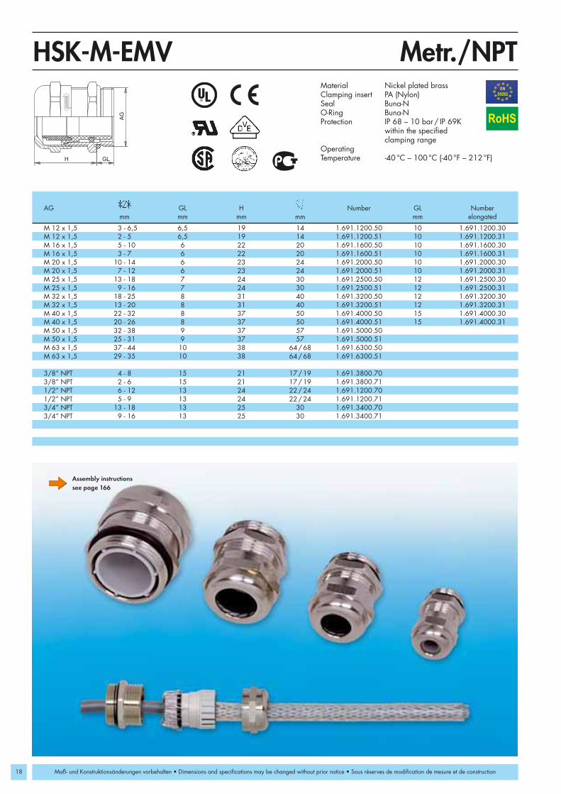
HSK-M-EMV EMI compatible standard strain relieffittings
HSK-M-Flex-EMV EMI compatible standard strain relieffittings with flex nut
HSK-M-EMV-D EMI compatible standard strain relieffittings with feed-through suitable for cables with braided or foil shield
HSK-MZ-EMV EMI compatible standard strain relieffittings with additional clamping provisions and flex protection
GM-EMV Special locking nut with cutting edges,suitable for plastic coated metal enclosures
Setting Standards
HSK-EMV-Industry Standard
18
M 12 x 1,5 3 - 6,5 6,5 19 14 1.691.1200.50 10 1.691.1200.30M 12 x 1,5 2 - 5 6,5 19 14 1.691.1200.51 10 1.691.1200.31M 16 x 1,5 5 - 10 6 22 20 1.691.1600.50 10 1.691.1600.30M 16 x 1,5 3 - 7 6 22 20 1.691.1600.51 10 1.691.1600.31M 20 x 1,5 10 - 14 6 23 24 1.691.2000.50 10 1.691.2000.30M 20 x 1,5 7 - 12 6 23 24 1.691.2000.51 10 1.691.2000.31M 25 x 1,5 13 - 18 7 24 30 1.691.2500.50 12 1.691.2500.30M 25 x 1,5 9 - 16 7 24 30 1.691.2500.51 12 1.691.2500.31M 32 x 1,5 18 - 25 8 31 40 1.691.3200.50 12 1.691.3200.30M 32 x 1,5 13 - 20 8 31 40 1.691.3200.51 12 1.691.3200.31M 40 x 1,5 22 - 32 8 37 50 1.691.4000.50 15 1.691.4000.30M 40 x 1,5 20 - 26 8 37 50 1.691.4000.51 15 1.691.4000.31M 50 x 1,5 32 - 38 9 37 57 1.691.5000.50M 50 x 1,5 25 - 31 9 37 57 1.691.5000.51M 63 x 1,5 37 - 44 10 38 64/68 1.691.6300.50M 63 x 1,5 29 - 35 10 38 64/68 1.691.6300.51
3/8” NPT 4 - 8 15 21 17/19 1.691.3800.703/8” NPT 2 - 6 15 21 17/19 1.691.3800.711/2” NPT 6 - 12 13 24 22/24 1.691.1200.701/2” NPT 5 - 9 13 24 22/24 1.691.1200.713/4” NPT 13 - 18 13 25 30 1.691.3400.703/4” NPT 9 - 16 13 25 30 1.691.3400.71
AG
H GL
Metr./NPTHSK-M-EMVEN50262
RoHS
Maß- und Konstruktionsänderungen vorbehalten • Dimensions and specifications may be changed without prior notice • Sous réserves de modification de mesure et de construction
Assembly instructionssee page 166
Material Nickel plated brassClamping insert PA (Nylon)Seal Buna-NO-Ring Buna-NProtection IP 68 – 10 bar / IP 69K
within the specified clamping range
OperatingTemperature -40 °C – 100 °C (-40 °F – 212 °F)
AG GL H Number GL Numbermm mm mm mm mm elongated

PG 7 3 - 6,5 5 19 14 1.691.0700.01 10 1.691.0700.60PG 7 2 - 5 5 19 14 1.691.0700.15 10 1.691.0700.61PG 9 4 - 8 6 21 17 1.691.0900.01 10 1.691.0900.60PG 9 2 - 6 6 21 17 1.691.0900.15 10 1.691.0900.61PG 11 5 - 10 6 22 20 1.691.1100.01 10 1.691.1100.60PG 11 3 - 7 6 22 20 1.691.1100.15 10 1.691.1100.61PG 13,5 6 - 12 6,5 24 22 1.691.1300.01 10 1.691.1300.60PG 13,5 5 - 9 6,5 24 22 1.691.1300.15 10 1.691.1300.61PG 16 10 - 14 6,5 23 24 1.691.1600.01 10 1.691.1600.60PG 16 7 - 12 6,5 23 24 1.691.1600.15 10 1.691.1600.61PG 21 13 - 18 7 24 30 1.691.2100.01 12 1.691.2100.60PG 21 9 - 16 7 24 30 1.691.2100.15 12 1.691.2100.61PG 29 18 - 25 8 29 40 1.691.2900.01 12 1.691.2900.60PG 29 13 - 20 8 29 40 1.691.2900.15 12 1.691.2900.61PG 36 22 - 32 8 35 50 1.691.3600.01 15 1.691.3600.60PG 36 20 - 26 8 35 50 1.691.3600.15 15 1.691.3600.61PG 42 32 - 38 9 37 57 1.691.4200.01 15 1.691.4200.60PG 42 25 - 31 9 37 57 1.691.4200.15 15 1.691.4200.61PG 48 37 - 44 10 38 64 1.691.4800.01 15 1.691.4800.60PG 48 29 - 35 10 38 64 1.691.4800.15 15 1.691.4800.61
AG
H GL
HSK-M-EMV
19
RoHS
Maß- und Konstruktionsänderungen vorbehalten • Dimensions and specifications may be changed without prior notice • Sous réserves de modification de mesure et de construction
PG/PG-elongated
AG GL H Number GL Numbermm mm mm mm mm elongated
Assembly instructionssee page 166
Material Nickel plated brassClamping insert PA (Nylon)Seal Buna-NO-Ring Buna-NProtection IP 68 – 10 bar / IP 69K
within the specified clamping rangeOperatingTemperature -40 °C – 100 °C (-40 °F – 212 °F)
Available also in PVDF, -35 °C – 150 °C (-31 °F – 302 °F)

20
M 12 x 1,5 3 - 6,5 6,5 55 6,8 14 1.624.1200.50 10 1.624.1200.30M 12 x 1,5 2 - 5 5 55 6,8 14 1.624.1200.51 10 1.624.1200.31M 16 x 1,5 5 - 10 6 77 10,3 20 1.624.1600.50 10 1.624.1600.30M 16 x 1,5 3 - 7 6 77 10,3 20 1.624.1600.51 10 1.624.1600.31M 20 x 1,5 10 - 14 6 98 14,3 24 1.624.2000.50 10 1.624.2000.30M 20 x 1,5 7 - 12 6 98 14,3 24 1.624.2000.51 10 1.624.2000.31M 25 x 1,5 13 - 18 7 111 18,4 30 1.624.2500.50 12 1.624.2500.30M 25 x 1,5 9 - 16 7 111 18,4 30 1.624.2500.51 12 1.624.2500.31
3/8” NPT 4 - 8 15 66 8,2 17/19 1.624.3800.703/8” NPT 2 - 6 15 66 8,2 17/19 1.624.3800.711/2” NPT 6 - 12 13 88 12,3 22/24 1.624.1200.701/2” NPT 5 - 9 13 88 12,3 22/24 1.624.1200.713/4” NPT 13 - 18 13 111 18,4 30 1.624.3400.703/4” NPT 9 - 16 13 111 18,4 30 1.624.3400.71
AG
GLH
d
Metr./NPTHSK-M-Flex-EMVEN50262
RoHS
Maß- und Konstruktionsänderungen vorbehalten • Dimensions and specifications may be changed without prior notice • Sous réserves de modification de mesure et de construction
Assembly instructionssee page 166
Material Nickel plated brassSteel spring 1.4310Clamping insert PA (Nylon)Seal Buna-NO-Ring Buna-NProtection IP 68 – 10 bar / IP 69K
within the specified clamping rangeOperatingTemperature -40 °C – 100 °C (-40 °F – 212 °F)
AG GL H d Number GL Numbermm mm mm mm mm mm elongated

PG 7 3 - 6,5 5 55 6,8 14 1.624.0700.01 10 1.624.0700.60PG 7 2 - 5 5 55 6,8 14 1.624.0700.15 10 1.624.0700.61PG 9 4 - 8 6 66 8,2 17 1.624.0900.01 10 1.624.0900.60PG 9 2 - 6 6 66 8,2 17 1.624.0900.15 10 1.624.0900.61PG 11 5 - 10 6 77 10,3 20 1.624.1100.01 10 1.624.1100.60PG 11 3 - 7 6 77 10,3 20 1.624.1100.15 10 1.624.1100.61PG 13,5 6 - 12 6,5 88 12,3 22 1.624.1300.01 10 1.624.1300.60PG 13,5 5 - 9 6,5 88 12,3 22 1.624.1300.15 10 1.624.1300.61PG 16 10 - 14 6,5 98 14,3 24 1.624.1600.01 10 1.624.1600.60PG 16 7 - 12 6,5 98 14,3 24 1.624.1600.15 10 1.624.1600.61PG 21 13 - 18 7 111 18,4 30 1.624.2100.01 12 1.624.2100.60PG 21 9 - 16 7 111 18,4 30 1.624.2100.15 12 1.624.2100.61
AG
GLH
d
HSK-M-Flex-EMV
21
RoHS
Maß- und Konstruktionsänderungen vorbehalten • Dimensions and specifications may be changed without prior notice • Sous réserves de modification de mesure et de construction
PG/PG-elongated
Assembly instructionssee page 166
Material Nickel plated brassSteel spring 1.4310Clamping insert PA (Nylon)Seal Buna-NO-Ring Buna-NProtection IP 68 – 10 bar / IP 69K
within the specified clamping rangeOperatingTemperature -40 °C – 100 °C (-40 °F – 212 °F)
Available also in PVDF, -35 °C – 150 °C (-31 °F – 302 °F)
AG GL H d Number GL Numbermm mm mm mm mm mm elongated

22
M 12 x 1,5 3 - 6,5 6,5 25 14 1.631.1200.50 10 1.631.1200.30M 16 x 1,5 4 - 8 6 29 17/19 1.631.1609.50 10 1.631.1609.30M 16 x 1,5 5 - 10 6 32 20 1.631.1600.50 10 1.631.1600.30M 20 x 1,5 6 - 12 6 32,5 22 1.631.2013.50 10 1.631.2013.30M 20 x 1,5 10 - 14 6 33 24 1.631.2000.50 10 1.631.2000.30M 25 x 1,5 13 - 18 7 39 30 1.631.2500.50 12 1.631.2500.30M 32 x 1,5 18 - 25 8 45 40 1.631.3200.50 12 1.631.3200.30M 40 x 1,5 24 - 32 8 51 50 1.631.4000.50 15 1.631.4000.30M 50 x 1,5 32 - 38 9 57,5 57 1.631.5000.50M 63 x 1,5 37 - 44 10 52 64/68 1.631.6300.50
PG 7 3 - 6,5 5 24 14 1.631.0700.01PG 9 4 - 8 6 28 17 1.631.0900.01PG 11 5 - 10 6 29 20 1.631.1100.01PG 13,5 6 - 12 6,5 31 22 1.631.1300.01PG 16 10 - 14 6,5 32 24 1.631.1600.01PG 21 13 - 18 7 38 30 1.631.2100.01PG 29 18 - 25 8 43 40 1.631.2900.01PG 36 24 - 32 8 48 50 1.631.3600.01PG 42 32 - 38 9 45 57 1.631.4200.01PG 48 37 - 44 10 46 64 1.631.4800.01
3/8" NPT 4 - 8 15 29 17/19 1.631.3800.701/2" NPT 6 - 12 13 32,5 22/24 1.631.1200.703/4" NPT 13 - 18 13 39 30 1.631.3400.70
AG
GLH
Metr./PG/NPTHSK-M-EMV-DEN50262
RoHS
Maß- und Konstruktionsänderungen vorbehalten • Dimensions and specifications may be changed without prior notice • Sous réserves de modification de mesure et de construction
Assembly instructionssee page 167
Material Nickel plated brassClamping insert Metal coated PA (Nylon)Seal Buna-NO-Ring Buna-NProtection IP 68 – 10 bar / IP 69K
within the specified clamping rangeOperatingTemperature -40 °C – 100 °C (-40 °F – 212 °F)
AG GL H Number GL Numbermm mm mm mm mm elongated
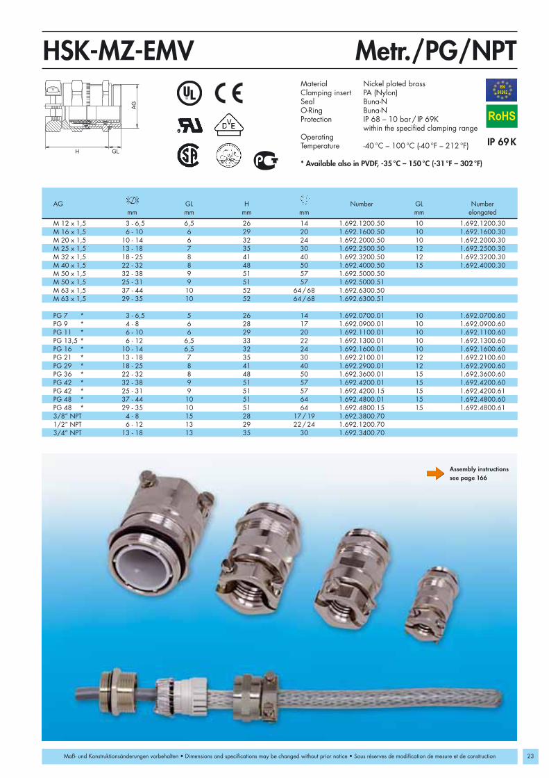
M 12 x 1,5 3 - 6,5 6,5 26 14 1.692.1200.50 10 1.692.1200.30M 16 x 1,5 6 - 10 6 29 20 1.692.1600.50 10 1.692.1600.30M 20 x 1,5 10 - 14 6 32 24 1.692.2000.50 10 1.692.2000.30M 25 x 1,5 13 - 18 7 35 30 1.692.2500.50 12 1.692.2500.30M 32 x 1,5 18 - 25 8 41 40 1.692.3200.50 12 1.692.3200.30M 40 x 1,5 22 - 32 8 48 50 1.692.4000.50 15 1.692.4000.30M 50 x 1,5 32 - 38 9 51 57 1.692.5000.50M 50 x 1,5 25 - 31 9 51 57 1.692.5000.51M 63 x 1,5 37 - 44 10 52 64/68 1.692.6300.50M 63 x 1,5 29 - 35 10 52 64/68 1.692.6300.51
PG 7 * 3 - 6,5 5 26 14 1.692.0700.01 10 1.692.0700.60PG 9 * 4 - 8 6 28 17 1.692.0900.01 10 1.692.0900.60PG 11 * 6 - 10 6 29 20 1.692.1100.01 10 1.692.1100.60PG 13,5 * 6 - 12 6,5 33 22 1.692.1300.01 10 1.692.1300.60PG 16 * 10 - 14 6,5 32 24 1.692.1600.01 10 1.692.1600.60PG 21 * 13 - 18 7 35 30 1.692.2100.01 12 1.692.2100.60PG 29 * 18 - 25 8 41 40 1.692.2900.01 12 1.692.2900.60PG 36 * 22 - 32 8 48 50 1.692.3600.01 15 1.692.3600.60PG 42 * 32 - 38 9 51 57 1.692.4200.01 15 1.692.4200.60PG 42 * 25 - 31 9 51 57 1.692.4200.15 15 1.692.4200.61PG 48 * 37 - 44 10 51 64 1.692.4800.01 15 1.692.4800.60PG 48 * 29 - 35 10 51 64 1.692.4800.15 15 1.692.4800.613/8” NPT 4 - 8 15 28 17/19 1.692.3800.701/2” NPT 6 - 12 13 29 22/24 1.692.1200.703/4” NPT 13 - 18 13 35 30 1.692.3400.70
H GL
AG
Metr./PG/NPTHSK-MZ-EMVEN50262
23
RoHS
Maß- und Konstruktionsänderungen vorbehalten • Dimensions and specifications may be changed without prior notice • Sous réserves de modification de mesure et de construction
Assembly instructionssee page 166
Material Nickel plated brassClamping insert PA (Nylon)Seal Buna-NO-Ring Buna-NProtection IP 68 – 10 bar / IP 69K
within the specified clamping rangeOperatingTemperature -40 °C – 100 °C (-40 °F – 212 °F)
* Available also in PVDF, -35 °C – 150 °C (-31 °F – 302 °F)
AG GL H Number GL Numbermm mm mm mm mm elongated

24
M 12 x 1,5 2,8 15 0,7 1.167.1200.50M 16 x 1,5 2,8 19 0,7 1.167.1600.50M 20 x 1,5 3,0 24 0,7 1.167.2000.50M 25 x 1,5 3,5 30 0,7 1.167.2500.50M 32 x 1,5 4,5 36 0,7 1.167.3200.50M 40 x 1,5 5,0 46 0,7 1.167.4000.50M 50 x 1,5 5,0 60 0,7 1.167.5000.50M 63 x 1,5 6,0 70 0,7 1.167.6300.50
PG 9 2,8 18 0,7 1.167.0900.01PG 11 3,0 21 0,7 1.167.1100.01PG 13,5 3,0 23 0,7 1.167.1300.01PG 16 3,0 26 0,7 1.167.1600.01PG 21 3,5 32 0,7 1.167.2100.01PG 29 4,0 41 0,7 1.167.2900.01PG 36 5,0 51 0,7 1.167.3600.01PG 42 5,0 60 0,7 1.167.4200.01PG 48 5,5 64 0,7 1.167.4800.01
H
IG
S
Metr./PGGM-EMVM
RoHS
Maß- und Konstruktionsänderungen vorbehalten • Dimensions and specifications may be changed without prior notice • Sous réserves de modification de mesure et de construction
Material Nickel plated brass
IG H S Numbermm mm mm

25
Setting Standards
Strain relief fittings in all popular thread types and sizes forstandard applications in the following areas:
• Machine, apparatus and plant equipment• Measuring control and feedback systems• Control cabinets• Chemical plants• Medical equipment• Railroad cars and vehicles• Power plants (hydro, gas, coal or wind)• Industrial installations
and in all applications where excellent performance, fireresistance, and resistance against turning of the cable arecritical.
METRICA-P New liquid tight strain relief fittings with metricthreads made of nylon 6/6
METRICA-M New liquid tight strain relief fittings with metricthreads made of nickel plated brass
HSK-K Standard liquid tight strain relief fittings made of nylon 6/6
HSK-M Standard liquid tight strain relief fittings made of nickel plated brass
HSK-KE/KR Enlarged and reduced liquid tight strain relieffittings made of nylon 6/6
HSK-K-MULTI Multi-hole liquid tight strain relief fittings made of nylon 6/6
HSK-M-MULTI Multi-hole liquid tight strain relief fittings made of nickel plated brass
HSK-K-FLAKA Liquid tight strain relief fittings for flat cables, made of nylon 6/6
HSK-M-FLAKA Liquid tight strain relief fittings for flat cables, made of nickel plated brass
HSK-K-PVDF Standard liquid tight strain relief fittings for chemi-cal & extreme temperature applications made ofPVDF
HSK-M-PVDF Standard liquid tight stain relief fittings for chemical & extreme temperature applicationsmade of nickel plated brass
HSK-INOX Standard liquid tight strain relief fittings made of stainless steel
HSK-MZ Standard liquid tight strain relief fittings withadditional pull-out resistance and flex protection,made of nickel plated brass
HSK-M-W folding snap elbow made of metal HSK-W Snap elbows made of nylon 6/6 or nickel plated
brass
HSK-Industry Standard

26
AG
GLH
Metr.METRICA-PEN50262
M 12 x 1,5 4 - 7 8 22 15 1.218.1200.50 1.218.1201.50 1.218.1202.50M 12 x 1,5 2 - 5 8 22 15 1.218.1200.51 1.218.1201.51 1.218.1202.51M 16 x 1,5 6 - 10 8 26 19 1.218.1600.50 1.218.1601.50 1.218.1602.50M 16 x 1,5 3 - 7 8 26 19 1.218.1600.51 1.218.1601.51 1.218.1602.51M 20 x 1,5 8 - 13 9 29 24 1.218.2000.50 1.218.2001.50 1.218.2002.50M 20 x 1,5 7 - 10 9 29 24 1.218.2000.51 1.218.2001.51 1.218.2002.51M 25 x 1,5 11 - 17 10 33 30 1.218.2500.50 1.218.2501.50 1.218.2502.50M 25 x 1,5 8 - 13 10 33 30 1.218.2500.51 1.218.2501.51 1.218.2502.51M 32 x 1,5 11 - 21 10 41 36 1.218.3200.50 1.218.3201.50 1.218.3202.50M 32 x 1,5 10 - 15 10 41 36 1.218.3200.51 1.218.3201.51 1.218.3202.51M 40 x 1,5 19 - 28 12 46 46 1.218.4000.50 1.218.4001.50 1.218.4002.50M 40 x 1,5 15 - 23 12 46 46 1.218.4000.51 1.218.4001.51 1.218.4002.51M 50 x 1,5 27 - 35 12 52 55 1.218.5000.50 1.218.5001.50 1.218.5002.50M 50 x 1,5 22 - 29 12 52 55 1.218.5000.51 1.218.5001.51 1.218.5002.51M 63 x 1,5 34 - 48 12 57 68 1.218.6300.50 1.218.6301.50 1.218.6302.50M 63 x 1,5 28 - 39 12 57 68 1.218.6300.51 1.218.6301.51 1.218.6302.51
RoHS
Maß- und Konstruktionsänderungen vorbehalten • Dimensions and constructions are subject to alterations without notice • Sous réserves de modification de mesure et de construction
Material PA (Nylon) V0 according to UL 94Seal Buna-NProtection IP 68 – 10 bar / IP 69K
(NEMA 6 – 150 PSIG)within the specified clamping rangeonly with optional O-Ring (see page 132)
OperatingTemperature -40 °C – 100 °C (-40 °F – 212 °F)Colors grey RAL 7035
black RAL 9005blue RAL 5012 for the intrinsic safety “i”
AG GL H Number Number Numbermm mm mm mm grey black blue

27
M 12 x 1,5 4 - 7 6 20 14 1.618.1200.50M 12 x 1,5 2 - 5 6 20 14 1.618.1200.51M 16 x 1,5 6 - 10 6 25 19 1.618.1600.50M 16 x 1,5 3 - 7 6 25 19 1.618.1600.51M 20 x 1,5 8 - 13 6,5 26 24 1.618.2000.50M 20 x 1,5 7 - 10 6,5 26 24 1.618.2000.51M 25 x 1,5 11 - 17 7 29 29 1.618.2500.50M 25 x 1,5 8 - 13 7 29 29 1.618.2500.51M 32 x 1,5 11 - 21 8 37 34 1.618.3200.50M 32 x 1,5 10 - 15 8 37 34 1.618.3200.51M 40 x 1,5 19 - 28 8 40,5 44 1.618.4000.50M 40 x 1,5 15 - 23 8 40,5 44 1.618.4000.51M 50 x 1,5 27 - 35 9 49,5 55 1.618.5000.50M 50 x 1,5 22 - 29 9 49,5 55 1.618.5000.51M 63 x 1,5 34 - 48 10 49 68 1.618.6300.50M 63 x 1,5 28 - 39 10 49 68 1.618.6300.51
AG
GLH
Metr.METRICA-MEN50262
RoHS
Maß- und Konstruktionsänderungen vorbehalten • Dimensions and constructions are subject to alterations without notice • Sous réserves de modification de mesure et de construction
Material Nickel plated brassClamping insert PA (Nylon)Seal Buna-NO-Ring Buna-NProtection IP 68 – 10 bar
within the specified clamping rangeOperatingTemperature -40 °C – 100 °C (-40 °F – 212 °F)
AG GL H Numbermm mm mm mm

28
M 12 x 1,5 4 - 7 15 22 15 1.218.1200.30 1.218.1201.30 1.218.1202.30M 12 x 1,5 2 - 5 15 22 15 1.218.1200.31 1.218.1201.31 1.218.1202.31M 16 x 1,5 6 - 10 15 26 19 1.218.1600.30 1.218.1601.30 1.218.1602.30M 16 x 1,5 3 - 7 15 26 19 1.218.1600.31 1.218.1601.31 1.218.1602.31M 20 x 1,5 8 - 13 15 29 24 1.218.2000.30 1.218.2001.30 1.218.2002.30M 20 x 1,5 7 - 10 15 29 24 1.218.2000.31 1.218.2001.31 1.218.2002.31M 25 x 1,5 11 - 17 15 33 30 1.218.2500.30 1.218.2501.30 1.218.2502.30M 25 x 1,5 8 - 13 15 33 30 1.218.2500.31 1.218.2501.31 1.218.2502.31M 32 x 1,5 11 - 21 15 41 36 1.218.3200.30 1.218.3201.30 1.218.3202.30M 32 x 1,5 10 - 15 15 41 36 1.218.3200.31 1.218.3201.31 1.218.3202.31M 40 x 1,5 19 - 28 18 46 46 1.218.4000.30 1.218.4001.30 1.218.4002.30M 40 x 1,5 15 - 23 18 46 46 1.218.4000.31 1.218.4001.31 1.218.4002.31M 50 x 1,5 27 - 35 18 52 55 1.218.5000.30 1.218.5001.30 1.218.5002.30M 50 x 1,5 22 - 29 18 52 55 1.218.5000.31 1.218.5001.31 1.218.5002.31M 63 x 1,5 34 - 48 18 57 68 1.218.6300.30 1.218.6301.30 1.218.6302.30M 63 x 1,5 28 - 39 18 57 68 1.218.6300.31 1.218.6301.31 1.218.6302.31
AG
GLH
METRICA-PEN50262
RoHS
Maß- und Konstruktionsänderungen vorbehalten • Dimensions and constructions are subject to alterations without notice • Sous réserves de modification de mesure et de construction
Metr.-elongatedMaterial PA (Nylon) V0 according to UL 94Seal Buna-NProtection IP 68 – 10 bar / IP 69K
(NEMA 6 – 150 PSIG)within the specified clamping rangeonly with optional O-Ring (see page 132)
OperatingTemperature -40 °C – 100 °C (-40 °F – 212 °F)Colors grey RAL 7035
black RAL 9005blue RAL 5012 for the intrinsic safety “i”
AG GL H Number Number Numbermm mm mm mm grey black blue

29
M 12 x 1,5 4 - 7 10 20 14 1.618.1200.30M 12 x 1,5 2 - 5 10 20 14 1.618.1200.31M 16 x 1,5 6 - 10 10 25 19 1.618.1600.30M 16 x 1,5 3 - 7 10 25 19 1.618.1600.31M 20 x 1,5 8 - 13 10 26 24 1.618.2000.30M 20 x 1,5 7 - 10 10 26 24 1.618.2000.31M 25 x 1,5 8 - 13 12 29 29 1.618.2500.30M 25 x 1,5 11 - 17 12 29 29 1.618.2500.31M 32 x 1,5 11 - 21 12 37 34 1.618.3200.30M 32 x 1,5 10 - 15 12 37 34 1.618.3200.31M 40 x 1,5 19 - 28 15 40,5 44 1.618.4000.30M 40 x 1,5 15 - 23 15 40,5 44 1.618.4000.31M 50 x 1,5 27 - 35 15 49,5 55 1.618.5000.30M 50 x 1,5 22 - 29 15 49,5 55 1.618.5000.31M 63 x 1,5 34 - 48 15 49 68 1.618.6300.30M 63 x 1,5 28 - 39 15 49 68 1.618.6300.31
AG
GLH
METRICA-MEN50262
RoHS
Maß- und Konstruktionsänderungen vorbehalten • Dimensions and constructions are subject to alterations without notice • Sous réserves de modification de mesure et de construction
Metr.-elongatedMaterial Nickel plated brassClamping insert PA (Nylon)Seal Buna-NO-Ring Buna-NProtection IP 68 – 10 bar
within the specified clamping rangeOperatingTemperature -40 °C – 100 °C (-40 °F – 212 °F)
AG GL H Numbermm mm mm mm

30
AG
H GL
Metr.HSK-KEN50262
M 12 x 1,5 3 - 6,5 8 21 15 1.209.1200.50 1.209.1201.50 1.209.1202.50M 12 x 1,5 2 - 5 8 21 15 1.209.1200.51 1.209.1201.51 1.209.1202.51M 16 x 1,5 4 - 8 8 22 19 1.209.1600.50 1.209.1601.50 1.209.1602.50M 16 x 1,5 2 - 6 8 22 19 1.209.1600.51 1.209.1601.51 1.209.1602.51M 16 x 1,5 5 - 10 8 25 22 1.219.1600.50 1.219.1601.50 1.219.1602.50M 20 x 1,5 6 - 12 9 27 24 1.209.2000.50 1.209.2001.50 1.209.2002.50M 20 x 1,5 5 - 9 9 27 24 1.209.2000.51 1.209.2001.51 1.209.2002.51M 20 x 1,5 10 - 14 9 28 27 1.219.2000.50 1.219.2001.50 1.219.2002.50M 25 x 1,5 13 - 18 11 31 33 1.209.2500.50 1.209.2501.50 1.209.2502.50M 25 x 1,5 9 - 16 11 31 33 1.209.2500.51 1.209.2501.51 1.209.2502.51M 32 x 1,5 18 - 25 11 39 42 1.209.3200.50 1.209.3201.50 1.209.3202.50M 32 x 1,5 13 - 20 11 39 42 1.209.3200.51 1.209.3201.51 1.209.3202.51M 40 x 1,5 22 - 32 13 48 53 1.209.4000.50 1.209.4001.50 1.209.4002.50M 40 x 1,5 20 - 26 13 48 53 1.209.4000.51 1.209.4001.51 1.209.4002.51M 50 x 1,5 32 - 38 13 49 60 1.209.5000.50 1.209.5001.50 1.209.5002.50M 50 x 1,5 25 - 31 13 49 60 1.209.5000.51 1.209.5001.51 1.209.5002.51M 63 x 1,5 37 - 44 14 49 65/68 1.209.6300.50 1.209.6301.50 1.209.6302.50M 63 x 1,5 29 - 35 14 49 65/68 1.209.6300.51 1.209.6301.51 1.209.6302.51
RoHS
Maß- und Konstruktionsänderungen vorbehalten • Dimensions and specifications may be changed without prior notice • Sous réserves de modification de mesure et de construction
Material PA (Nylon) V0 according to UL 94Seal Buna-NProtection IP 68 – 10 bar / IP 69K
(NEMA 6 – 150 PSIG)within the specified clamping rangeonly with optional O-Ring (see page 132)
OperatingTemperature -40 °C – 100 °C (-40 °F – 212 °F)Colors grey RAL 7035
black RAL 9005blue RAL 5012 for the intrinsic safety “i”
AG GL H Number Number Numbermm mm mm mm grey black blue

M 12 x 1,5 3 - 6,5 6,5 19 14 1.609.1200.50M 12 x 1,5 2 - 5 6,5 19 14 1.609.1200.51M 16 x 1,5 4 - 8 6 21 17/19 1.609.1600.50M 16 x 1,5 2 - 6 6 21 17/19 1.609.1600.51M 16 x 1,5 5 - 10 6 22 20 1.609.1611.50M 20 x 1,5 6 - 12 6 23 22 1.609.2000.50M 20 x 1,5 5 - 9 6 23 22 1.609.2000.51M 20 x 1,5 10 - 14 6 24 24 1.609.2016.50M 25 x 1,5 13 - 18 7 26 30 1.609.2500.50M 25 x 1,5 9 - 16 7 26 30 1.609.2500.51M 32 x 1,5 18 - 25 8 31 40 1.609.3200.50M 32 x 1,5 13 - 20 8 31 40 1.609.3200.51M 40 x 1,5 22 - 32 8 37 50 1.609.4000.50M 40 x 1,5 20 - 26 8 37 50 1.609.4000.51M 50 x 1,5 32 - 38 9 37 57 1.609.5000.50M 50 x 1,5 25 - 31 9 37 57 1.609.5000.51M 63 x 1,5 37 - 44 10 38 64/68 1.609.6300.50M 63 x 1,5 29 - 35 10 38 64/68 1.609.6300.51
AG
H GL
Metr.HSK-MEN50262
31
RoHS
Maß- und Konstruktionsänderungen vorbehalten • Dimensions and specifications may be changed without prior notice • Sous réserves de modification de mesure et de construction
Material Nickel plated brassClamping insert PA (Nylon)Seal Buna-NO-Ring Buna-NProtection IP 68 – 10 bar / IP 69K
within the specified clamping range
OperatingTemperature -40 °C – 100 °C (-40 °F – 212 °F)
AG GL H Numbermm mm mm mm

32
M 12 x 1,5 3 - 6,5 15 21 15 1.209.1200.30 1.209.1201.30 1.209.1202.30M 12 x 1,5 2 - 5 15 21 15 1.209.1200.31 1.209.1201.31 1.209.1202.31M 16 x 1,5 4 - 8 15 22 19 1.209.1600.30 1.209.1601.30 1.209.1602.30M 16 x 1,5 2 - 6 15 22 19 1.209.1600.31 1.209.1601.31 1.209.1602.31M 16 x 1,5 5 - 10 15 25 22 1.219.1600.30 1.219.1601.30 1.219.1602.30M 20 x 1,5 6 - 12 15 27 24 1.209.2000.30 1.209.2001.30 1.209.2002.30M 20 x 1,5 5 - 9 15 27 24 1.209.2000.31 1.209.2001.31 1.209.2002.31M 20 x 1,5 10 - 14 15 28 27 1.219.2000.30 1.219.2001.30 1.219.2002.30M 25 x 1,5 13 - 18 15 31 33 1.209.2500.30 1.209.2501.30 1.209.2502.30M 25 x 1,5 9 - 16 15 31 33 1.209.2500.31 1.209.2501.31 1.209.2502.31M 32 x 1,5 18 - 25 15 39 42 1.209.3200.30 1.209.3201.30 1.209.3202.30M 32 x 1,5 13 - 20 15 39 42 1.209.3200.31 1.209.3201.31 1.209.3202.31M 40 x 1,5 22 - 32 18 48 53 1.209.4000.30 1.209.4001.30 1.209.4002.30M 40 x 1,5 20 - 26 18 48 53 1.209.4000.31 1.209.4001.31 1.209.4002.31M 50 x 1,5 32 - 38 18 49 60 1.209.5000.30 1.209.5001.30 1.209.5002.30M 50 x 1,5 25 - 31 18 49 60 1.209.5000.31 1.209.5001.31 1.209.5002.31M 63 x 1,5 37 - 44 18 49 65/68 1.209.6300.30 1.209.6301.30 1.209.6302.30M 63 x 1,5 29 - 35 18 49 65/68 1.209.6300.31 1.209.6301.31 1.209.6302.31
AG
H GL
HSK-KEN50262
RoHS
Maß- und Konstruktionsänderungen vorbehalten • Dimensions and specifications may be changed without prior notice • Sous réserves de modification de mesure et de construction
Metr.-elongatedMaterial PA (Nylon) V0 according to UL 94Seal Buna-NProtection IP 68 – 10 bar / IP 69K
(NEMA 6 – 150 PSIG)within the specified clamping rangeonly with optional O-Ring (see page 132)
OperatingTemperature -40 °C – 100 °C (-40 °F – 212 °F)Colors grey RAL 7035
black RAL 9005blue RAL 5012 for the intrinsic safety “i”
AG GL H Number Number Numbermm mm mm mm grey black blue

M 12 x 1,5 3 - 6,5 10 19 14 1.609.1200.30M 12 x 1,5 2 - 5 10 19 14 1.609.1200.31M 16 x 1,5 4 - 8 10 21 17/19 1.609.1600.30M 16 x 1,5 2 - 6 10 21 17/19 1.609.1600.31M 16 x 1,5 5 - 10 10 22 20 1.609.1611.30M 20 x 1,5 6 - 12 10 23 22 1.609.2000.30M 20 x 1,5 5 - 9 10 23 22 1.609.2000.31M 20 x 1,5 10 - 14 10 24 24 1.609.2016.30M 25 x 1,5 13 - 18 12 26 30 1.609.2500.30M 25 x 1,5 9 - 16 12 26 30 1.609.2500.31M 32 x 1,5 18 - 25 12 31 40 1.609.3200.30M 32 x 1,5 13 - 20 12 31 40 1.609.3200.31M 40 x 1,5 22 - 32 15 37 50 1.609.4000.30M 40 x 1,5 20 - 26 15 37 50 1.609.4000.31M 50 x 1,5 32 - 38 15 37 57 1.609.5000.30M 50 x 1,5 25 - 31 15 37 57 1.609.5000.31M 63 x 1,5 37 - 44 15 38 64/68 1.609.6300.30M 63 x 1,5 29 - 35 15 38 64/68 1.609.6300.31
AG
H GL
HSK-MEN50262
33
RoHS
Maß- und Konstruktionsänderungen vorbehalten • Dimensions and specifications may be changed without prior notice • Sous réserves de modification de mesure et de construction
Metr.-elongatedMaterial Nickel plated brassClamping insert PA (Nylon)Seal Buna-NO-Ring Buna-NProtection IP 68 – 10 bar / IP 69K
within the specified clamping rangeOperatingTemperature -40 °C – 100 °C (-40 °F – 212 °F)
AG GL H Numbermm mm mm mm

34
PG 7 3 - 6,5 8 21 15 1.209.0700.14 1.209.0701.14 1.209.0702.14PG 7 2 - 5 8 21 15 1.209.0700.15 1.209.0701.15 1.209.0702.15PG 9 4 - 8 8 22 19 1.209.0900.14 1.209.0901.14 1.209.0902.14PG 9 2 - 6 8 22 19 1.209.0900.15 1.209.0901.15 1.209.0902.15PG 11 5 - 10 8 25 22 1.209.1100.14 1.209.1101.14 1.209.1102.14PG 11 3 - 7 8 25 22 1.209.1100.15 1.209.1101.15 1.209.1102.15PG 13,5 6 - 12 9 27 24 1.209.1300.14 1.209.1301.14 1.209.1302.14PG 13,5 5 - 9 9 27 24 1.209.1300.15 1.209.1301.15 1.209.1302.15PG 16 10 - 14 10 28 27 1.209.1600.14 1.209.1601.14 1.209.1602.14PG 16 7 - 12 10 28 27 1.209.1600.15 1.209.1601.15 1.209.1602.15PG 21 13 - 18 11 31 33 1.209.2100.14 1.209.2101.14 1.209.2102.14PG 21 9 - 16 11 31 33 1.209.2100.15 1.209.2101.15 1.209.2102.15PG 29 18 - 25 11 39 42 1.209.2900.14 1.209.2901.14 1.209.2902.14PG 29 13 - 20 11 39 42 1.209.2900.15 1.209.2901.15 1.209.2902.15PG 36 22 - 32 13 48 53 1.209.3600.14 1.209.3601.14 1.209.3602.14PG 36 20 - 26 13 48 53 1.209.3600.15 1.209.3601.15 1.209.3602.15PG 42 32 - 38 13 49 60 1.209.4200.14 1.209.4201.14 1.209.4202.14PG 42 25 - 31 13 49 60 1.209.4200.15 1.209.4201.15 1.209.4202.15PG 48 37 - 44 14 49 65 1.209.4800.14 1.209.4801.14 1.209.4802.14PG 48 29 - 35 14 49 65 1.209.4800.15 1.209.4801.15 1.209.4802.15
AG
H GL
PGHSK-KRoHS
Maß- und Konstruktionsänderungen vorbehalten • Dimensions and specifications may be changed without prior notice • Sous réserves de modification de mesure et de construction
Material PA (Nylon) V0 according to UL 94Seal Buna-NProtection IP 68 – 10 bar / IP 69K
(NEMA 6 – 150 PSIG) within the specified clamping rangeonly with optional O-Ring (see page 132)
OperatingTemperature -40 °C – 100 °C (-40 °F – 212 °F)Colors grey RAL 7035
black RAL 9005blue RAL 5012 for the intrinsic safety “i”
AG GL H Number Number Numbermm mm mm mm grey black blue

PG 7 3 - 6,5 5 19 14 1.609.0700.01 10 1.609.0700.60PG 7 2 - 5 5 19 14 1.609.0700.15 10 1.609.0700.61PG 9 4 - 8 6 21 17 1.609.0900.01 10 1.609.0900.60PG 9 2 - 6 6 21 17 1.609.0900.15 10 1.609.0900.61PG 11 5 - 10 6 22 20 1.609.1100.01 10 1.609.1100.60PG 11 3 - 7 6 22 20 1.609.1100.15 10 1.609.1100.61PG 13,5 6 - 12 6,5 24 22 1.609.1300.01 10 1.609.1300.60PG 13,5 5 - 9 6,5 24 22 1.609.1300.15 10 1.609.1300.61PG 16 10 - 14 6,5 23 24 1.609.1600.01 10 1.609.1600.60PG 16 7 - 12 6,5 23 24 1.609.1600.15 10 1.609.1600.61PG 21 13 - 18 7 24 30 1.609.2100.01 12 1.609.2100.60PG 21 9 - 16 7 24 30 1.609.2100.15 12 1.609.2100.61PG 29 18 - 25 8 29 40 1.609.2900.01 12 1.609.2900.60PG 29 13 - 20 8 29 40 1.609.2900.15 12 1.609.2900.61PG 36 22 - 32 8 35 50 1.609.3600.01 15 1.609.3600.60PG 36 20 - 26 8 35 50 1.609.3600.15 15 1.609.3600.61PG 42 32 - 38 9 37 57 1.609.4200.01 15 1.609.4200.60PG 42 25 - 31 9 37 57 1.609.4200.15 15 1.609.4200.61PG 48 37 - 44 10 38 64 1.609.4800.01 15 1.609.4800.60PG 48 29 - 35 10 38 64 1.609.4800.15 15 1.609.4800.61
AG
H GL
HSK-M
35
RoHS
Maß- und Konstruktionsänderungen vorbehalten • Dimensions and specifications may be changed without prior notice • Sous réserves de modification de mesure et de construction
PG/PG-elongatedMaterial Nickel plated brassClamping insert PA (Nylon)Seal Buna-NO-Ring Buna-NProtection IP 68 – 10 bar / IP 69K (NEMA 6 – 150 PSIG)
within the specified clamping rangeOperatingTemperature -40 °C – 100 °C (-40 °F – 212 °F)
AG GL H Number GL Numbermm mm mm mm mm elongated

36
PG 7 3 - 6,5 15 21 15 1.209.0700.60 1.209.0701.60 1.209.0702.60PG 7 2 - 5 15 21 15 1.209.0700.61 1.209.0701.61 1.209.0702.61PG 9 4 - 8 15 22 19 1.209.0900.60 1.209.0901.60 1.209.0902.60PG 9 2 - 6 15 22 19 1.209.0900.61 1.209.0901.61 1.209.0902.61PG 11 5 - 10 15 25 22 1.209.1100.60 1.209.1101.60 1.209.1102.60PG 11 3 - 7 15 25 22 1.209.1100.61 1.209.1101.61 1.209.1102.61PG 13,5 6 - 12 15 27 24 1.209.1300.60 1.209.1301.60 1.209.1302.60PG 13,5 5 - 9 15 27 24 1.209.1300.61 1.209.1301.61 1.209.1302.61PG 16 10 - 14 15 28 27 1.209.1600.60 1.209.1601.60 1.209.1602.60PG 16 7 - 12 15 28 27 1.209.1600.61 1.209.1601.61 1.209.1602.61PG 21 13 - 18 15 31 33 1.209.2100.60 1.209.2101.60 1.209.2102.60PG 21 9 - 16 15 31 33 1.209.2100.61 1.209.2101.61 1.209.2102.61PG 29 18 - 25 15 39 42 1.209.2900.60 1.209.2901.60 1.209.2902.60PG 29 13 - 20 15 39 42 1.209.2900.61 1.209.2901.61 1.209.2902.61PG 36 22 - 32 18 48 53 1.209.3600.60 1.209.3601.60 1.209.3602.60PG 36 20 - 26 18 48 53 1.209.3600.61 1.209.3601.61 1.209.3602.61PG 42 32 - 38 18 49 60 1.209.4200.60 1.209.4201.60 1.209.4202.60PG 42 25 - 31 18 49 60 1.209.4200.61 1.209.4201.61 1.209.4202.61PG 48 37 - 44 18 49 65 1.209.4800.60 1.209.4801.60 1.209.4802.60PG 48 29 - 35 18 49 65 1.209.4800.61 1.209.4801.61 1.209.4802.61
AG
H GL
HSK-KRoHS
Maß- und Konstruktionsänderungen vorbehalten • Dimensions and specifications may be changed without prior notice • Sous réserves de modification de mesure et de construction
PG-elongatedMaterial PA (Nylon) V0 according to UL 94Seal Buna-NProtection IP 68 – 10 bar / IP 69K
(NEMA 6 – 150 PSIG) within the specified clamping rangeonly with optional O-Ring (see page 132)
OperatingTemperature -40 °C – 100 °C (-40 °F – 212 °F)Colors grey RAL 7035
black RAL 9005blue RAL 5012 for the intrinsic safety “i”
AG GL H Number Number Numbermm mm mm mm grey black blue
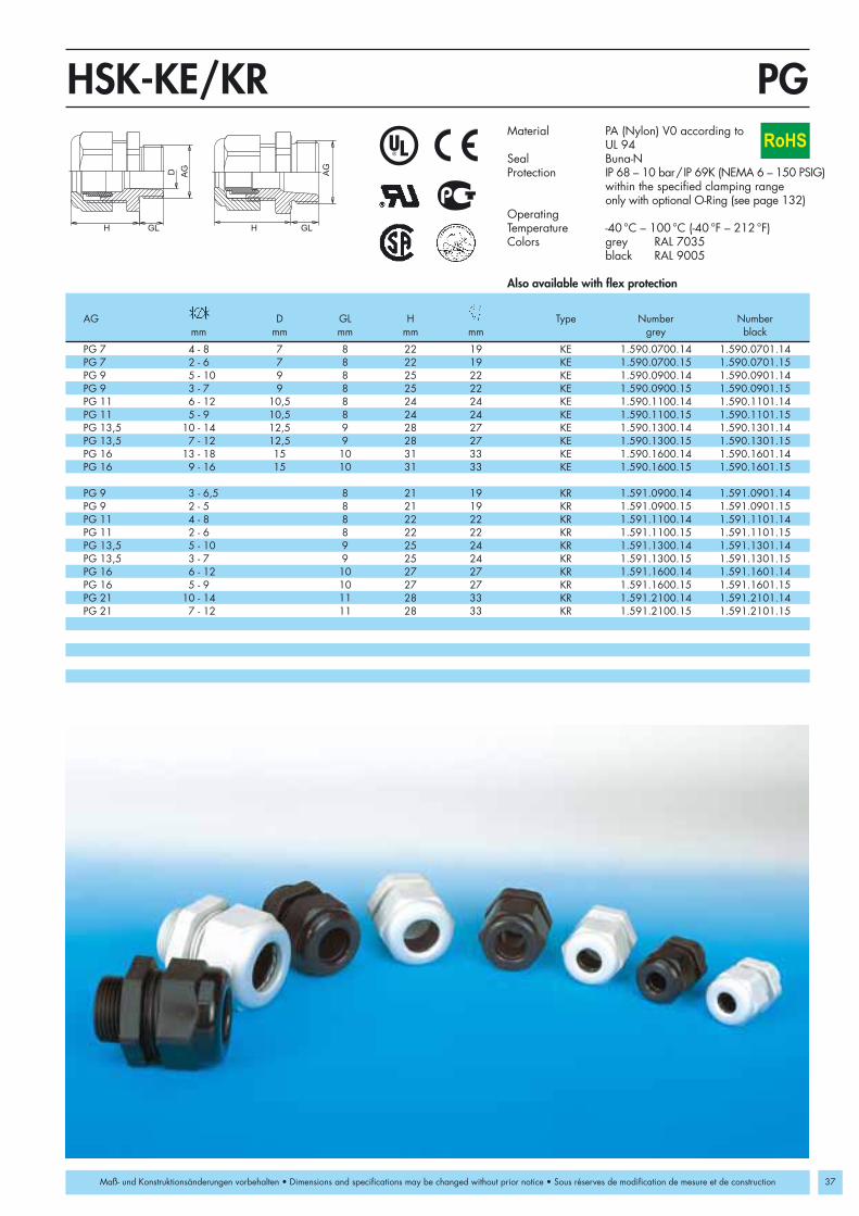
PG 7 4 - 8 7 8 22 19 KE 1.590.0700.14 1.590.0701.14PG 7 2 - 6 7 8 22 19 KE 1.590.0700.15 1.590.0701.15PG 9 5 - 10 9 8 25 22 KE 1.590.0900.14 1.590.0901.14PG 9 3 - 7 9 8 25 22 KE 1.590.0900.15 1.590.0901.15PG 11 6 - 12 10,5 8 24 24 KE 1.590.1100.14 1.590.1101.14PG 11 5 - 9 10,5 8 24 24 KE 1.590.1100.15 1.590.1101.15PG 13,5 10 - 14 12,5 9 28 27 KE 1.590.1300.14 1.590.1301.14PG 13,5 7 - 12 12,5 9 28 27 KE 1.590.1300.15 1.590.1301.15PG 16 13 - 18 15 10 31 33 KE 1.590.1600.14 1.590.1601.14PG 16 9 - 16 15 10 31 33 KE 1.590.1600.15 1.590.1601.15
PG 9 3 - 6,5 8 21 19 KR 1.591.0900.14 1.591.0901.14PG 9 2 - 5 8 21 19 KR 1.591.0900.15 1.591.0901.15PG 11 4 - 8 8 22 22 KR 1.591.1100.14 1.591.1101.14PG 11 2 - 6 8 22 22 KR 1.591.1100.15 1.591.1101.15PG 13,5 5 - 10 9 25 24 KR 1.591.1300.14 1.591.1301.14PG 13,5 3 - 7 9 25 24 KR 1.591.1300.15 1.591.1301.15PG 16 6 - 12 10 27 27 KR 1.591.1600.14 1.591.1601.14PG 16 5 - 9 10 27 27 KR 1.591.1600.15 1.591.1601.15PG 21 10 - 14 11 28 33 KR 1.591.2100.14 1.591.2101.14PG 21 7 - 12 11 28 33 KR 1.591.2100.15 1.591.2101.15
AG
D
H GL H GL
AG
PGHSK-KE/KR
37
RoHS
Maß- und Konstruktionsänderungen vorbehalten • Dimensions and specifications may be changed without prior notice • Sous réserves de modification de mesure et de construction
AG D GL H Type Number Numbermm mm mm mm mm grey black
Material PA (Nylon) V0 according to UL 94
Seal Buna-NProtection IP 68 – 10 bar/IP 69K (NEMA 6 – 150 PSIG)
within the specified clamping range only with optional O-Ring (see page 132)
OperatingTemperature -40 °C – 100 °C (-40 °F – 212 °F)Colors grey RAL 7035
black RAL 9005
Also available with flex protection

38
3/8” NPT 4 - 8 15 22 22/19 1.209.3800.70 1.209.3801.70 1.209.3802.703/8” NPT 2 - 6 15 22 22/19 1.209.3800.71 1.209.3801.71 1.209.3802.711/2” NPT 6 - 12 13 27 24 1.209.1200.70 1.209.1201.70 1.209.1202.701/2” NPT 5 - 9 13 27 24 1.209.1200.71 1.209.1201.71 1.209.1202.711/2” NPT/16 10 - 14 13 28 27 1.209.1216.70 1.209.1217.70 1.209.1218.701/2” NPT/16 7 - 12 13 28 27 1.209.1216.71 1.209.1217.71 1.209.1218.713/4” NPT 13 - 18 14 31 33 1.209.3400.70 1.209.3401.70 1.209.3402.703/4” NPT 9 - 16 14 31 33 1.209.3400.71 1.209.3401.71 1.209.3402.711” NPT 18 - 25 19 39 42 1.209.1000.70 1.209.1001.70 1.209.1002.701” NPT 13 - 20 19 39 42 1.209.1000.71 1.209.1001.71 1.209.1002.711 1/4” NPT 18 - 25 16 39 46/42 1.209.5400.70 1.209.5401.70 1.209.5402.701 1/4” NPT 13 - 20 16 39 46/42 1.209.5400.71 1.209.5401.71 1.209.5402.711 1/2” NPT 22 - 32 20 48 53 1.209.6400.70 1.209.6401.70 1.209.6402.701 1/2” NPT 20 - 26 20 48 53 1.209.6400.71 1.209.6401.71 1.209.6402.71
AG
H GL
NPTHSK-KRoHS
Maß- und Konstruktionsänderungen vorbehalten • Dimensions and specifications may be changed without prior notice • Sous réserves de modification de mesure et de construction
Material PA (Nylon) V0 according to UL 94Seal Buna-NProtection IP 68 – 10 bar / IP 69K
(NEMA 6 – 150 PSIG) within the specified clamping rangeonly with optional O-Ring (see page 132)
OperatingTemperature -40 °C – 100 °C (-40 °F – 212 °F)Colors grey RAL 7035
black RAL 9005blue RAL 5012 for the intrinsic safety “i”
AG GL H Number Number Numbermm mm mm mm grey black blue

3/8” NPT 4 - 8 15 21 17/19 1.609.3800.703/8” NPT 2 - 6 15 21 17/19 1.609.3800.711/2” NPT 6 - 12 13 24 22/24 1.609.1200.701/2” NPT 5 - 9 13 24 22/24 1.609.1200.713/4” NPT 13 - 18 13 25 30 1.609.3400.703/4” NPT 9 - 16 13 25 30 1.609.3400.711” NPT 18 - 25 19 29 40 1.609.1000.701” NPT 13 - 20 19 29 40 1.609.1000.71
AG
H GL
NPTHSK-M
39
RoHS
Maß- und Konstruktionsänderungen vorbehalten • Dimensions and specifications may be changed without prior notice • Sous réserves de modification de mesure et de construction
Material Nickel plated brassClamping insert PA (Nylon)Seal Buna-NO-Ring Buna-NProtection IP 68 – 10 bar / IP 69K (NEMA 6 – 150 PSIG)
within the specified clamping range OperatingTemperature -40 °C – 100 °C (-40 °F – 212 °F)
AG GL H Numbermm mm mm mm

40
M 16 x 1,5 8 22 19 4 x 1,4 1.597.1600.50 1.597.1600.51 2 x 3 1.597.1601.50 1.597.1601.51M 20 x 1,5 9 27 24 6 x 3 1.597.2001.50 1.597.2001.51 2 x 5 1.597.2003.50 1.597.2003.51M 25 x 1,5 11 31 33 4 x 6 1.597.2500.50 1.597.2500.51 3 x 7 1.597.2501.50 1.597.2501.51M 32 x 1,5 11 39 42 6 x 6,5 1.597.3200.50 1.597.3200.51 4 x 9 1.597.3201.50 1.597.3201.51M 40 x 1,5 13 48 53 7 x 9 1.597.4001.50 1.597.4001.51 2 x 15 1.597.4003.50 1.597.4003.51M 50 x 1,5 13 49 60 1.597.5099.50 1.597.5099.51M 63 x 1,5 14 49 65/68 6 x12 1.597.6301.50 1.597.6301.51 3 x 18 1.597.6302.50 1.597.6302.51
PG 9 8 22 19 4 x 1,4 1.597.0900.00 1.597.0900.01 2 x 3 1.597.0901.00 1.597.0901.01PG 11 8 25 22 2 x 4 1.597.1102.00 1.597.1102.01 3 x 3 1.597.1101.00 1.597.1101.01PG 13,5 9 27 24 3 x 4 1.597.1302.00 1.597.1302.01 2 x 5 1.597.1303.00 1.597.1303.01PG 16 10 28 27 4 x 4 1.597.1602.00 1.597.1602.01 6 x 4 1.597.1604.00 1.597.1604.01PG 16 10 28 27 3 x 5,6 1.597.1606.00 1.597.1606.01 2 x 6 1.597.1605.00 1.597.1605.01PG 21 11 31 33 4 x 6 1.597.2100.00 1.597.2100.01 3 x 7 1.597.2101.00 1.597.2101.01PG 29 11 39 42 6 x 6,5 1.597.2900.00 1.597.2900.01 4 x 9 1.597.2901.00 1.597.2901.01PG 36 13 48 53 7 x 9 1.597.3601.00 1.597.3601.01 2 x 15 1.597.3603.00 1.597.3603.01PG 48 14 49 65 6 x 12 1.597.4801.00 1.597.4801.01 3 x 18 1.597.4802.00 1.597.4802.01
3/8" NPT 15 22 19/22 4 x 1,4 1.597.3800.70 1.597.3800.71 2 x 3 1.597.3801.70 1.597.3801.711/2" NPT 13 27 24 3 x 4 1.597.1202.70 1.597.1202.71 2 x 5 1.597.1203.70 1.597.1203.711/2" NPT 16 13 28 27 6 x 4 1.597.1220.70 1.597.1220.71 2 x 6 1.597.1221.70 1.597.1221.713/4" NPT 14 31 33 4 x 6 1.597.3400.70 1.597.3400.71 3 x 7 1.597.3401.70 1.597.3401.711" NPT 19 39 42 6 x 6,5 1.597.1000.70 1.597.1000.71 4 x 9 1.597.1001.70 1.597.1001.711 1/4" NPT 16 39 42/46 1.597.5499.70 1.597.5499.711 1/2" NPT 20 48 53 5 x 9 1.597.6400.70 1.597.6400.71 7 x 9 1.597.6401.70 1.597.6401.71
AG
H GL
Metr./PG/NPTHSK-K-MultiM
RoHS
Maß- und Konstruktionsänderungen vorbehalten • Dimensions and specifications may be changed without prior notice • Sous réserves de modification de mesure et de construction
Number NumberAG GL H of Holes Number Number of Holes Number Number
mm mm mm x d grey black x d grey black
Material PA (Nylon) V0 according to UL 94Seal ElastomerProtection IP 65 (NEMA 4x)
IP 68 possible with ideal fitOperatingTemperature -40 °C – 100 °C (-40 °F – 212 °F)Colors grey RAL 7035
black RAL 9005
These inserts are examples, other inserts available upon requestInstallation instructions see page 162
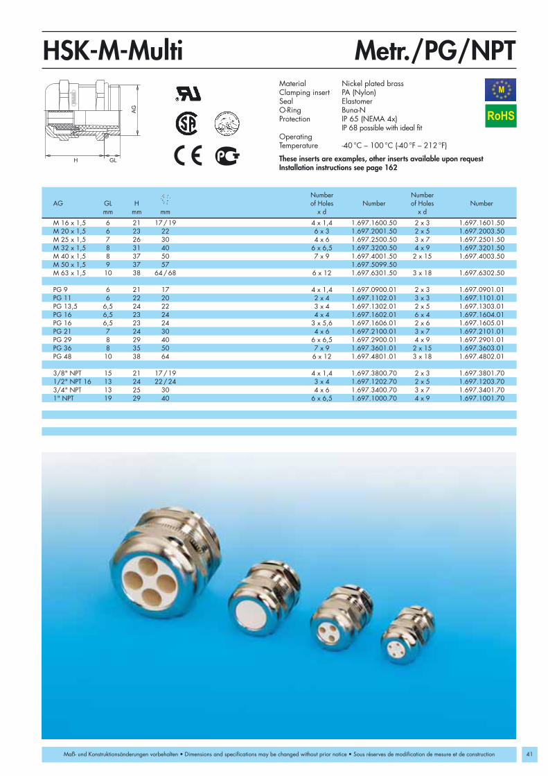
M 16 x 1,5 6 21 17/19 4 x 1,4 1.697.1600.50 2 x 3 1.697.1601.50M 20 x 1,5 6 23 22 6 x 3 1.697.2001.50 2 x 5 1.697.2003.50M 25 x 1,5 7 26 30 4 x 6 1.697.2500.50 3 x 7 1.697.2501.50M 32 x 1,5 8 31 40 6 x 6,5 1.697.3200.50 4 x 9 1.697.3201.50M 40 x 1,5 8 37 50 7 x 9 1.697.4001.50 2 x 15 1.697.4003.50M 50 x 1,5 9 37 57 1.697.5099.50M 63 x 1,5 10 38 64/68 6 x 12 1.697.6301.50 3 x 18 1.697.6302.50
PG 9 6 21 17 4 x 1,4 1.697.0900.01 2 x 3 1.697.0901.01PG 11 6 22 20 2 x 4 1.697.1102.01 3 x 3 1.697.1101.01PG 13,5 6,5 24 22 3 x 4 1.697.1302.01 2 x 5 1.697.1303.01PG 16 6,5 23 24 4 x 4 1.697.1602.01 6 x 4 1.697.1604.01PG 16 6,5 23 24 3 x 5,6 1.697.1606.01 2 x 6 1.697.1605.01PG 21 7 24 30 4 x 6 1.697.2100.01 3 x 7 1.697.2101.01PG 29 8 29 40 6 x 6,5 1.697.2900.01 4 x 9 1.697.2901.01PG 36 8 35 50 7 x 9 1.697.3601.01 2 x 15 1.697.3603.01PG 48 10 38 64 6 x 12 1.697.4801.01 3 x 18 1.697.4802.01
3/8" NPT 15 21 17/19 4 x 1,4 1.697.3800.70 2 x 3 1.697.3801.701/2" NPT 16 13 24 22/24 3 x 4 1.697.1202.70 2 x 5 1.697.1203.703/4" NPT 13 25 30 4 x 6 1.697.3400.70 3 x 7 1.697.3401.701" NPT 19 29 40 6 x 6,5 1.697.1000.70 4 x 9 1.697.1001.70
AG
GLH
Metr./PG/NPTHSK-M-MultiM
41
RoHS
Maß- und Konstruktionsänderungen vorbehalten • Dimensions and specifications may be changed without prior notice • Sous réserves de modification de mesure et de construction
Material Nickel plated brassClamping insert PA (Nylon)Seal ElastomerO-Ring Buna-NProtection IP 65 (NEMA 4x)
IP 68 possible with ideal fitOperatingTemperature -40 °C – 100 °C (-40 °F – 212 °F)
These inserts are examples, other inserts available upon requestInstallation instructions see page 162
Number NumberAG GL H of Holes Number of Holes Number
mm mm mm x d x d

42
M 20 x 1,5 9 28 27 11,5 x 5 1.587.2016.50 1.587.2016.51 12 x 7 1.587.2017.50 1.587.2017.51M 20 x 1,5 9 28 27 14 x 6 1.587.2018.50 1.587.2018.51M 25 x 1,5 11 31 33 14 x 6 1.587.2500.50 1.587.2500.51 14 x 7 1.587.2501.50 1.587.2501.51M 32 x 1,5 11 39 42 22 x 8 1.587.3200.50 1.587.3200.51M 40 x 1,5 13 48 53 28,5 x 10 1.587.4000.50 1.587.4000.51 29 x 5,5 1.587.4001.50 1.587.4001.51M 40 x 1,5 13 48 53 30,5 x 12 1.587.4002.50 1.587.4002.51 31 x 7,5 1.587.4003.50 1.587.4003.51M 50 x 1,5 13 49 60 33,5 x 11,5 1.587.5000.50 1.587.5000.51M 63 x 1,5 14 49 65/68 38 x 12 1.587.6300.50 1.587.6301.51
PG 16 10 28 27 11,5 x 5 1.587.1600.00 1.587.1600.01 12 x 7 1.587.1601.00 1.587.1601.01PG 16 10 28 27 14 x 6 1.587.1602.00 1.587.1602.01PG 21 11 31 33 14 x 6 1.587.2100.00 1.587.2100.01 14 x 7 1.587.2101.00 1.587.2101.01PG 29 11 39 42 22 x 8 1.587.2900.00 1.587.2900.01PG 36 13 48 53 28,5 x 10 1.587.3600.00 1.587.3600.01 29 x 5,5 1.587.3601.00 1.587.3601.01PG 36 13 48 53 30,5 x 12 1.587.3602.00 1.587.3602.01 31 x 7,5 1.587.3603.00 1.587.3603.01PG 42 13 49 60 33,5 x 11,5 1.587.4200.00 1.587.4200.01PG 48 14 49 65 38 x 12 1.587.4800.00 1.587.4800.01
1/2” NPT/16 13 28 27 11,5 x 5,5 1.587.1216.70 1.587.1216.71 12 x 7 1.587.1217.70 1.587.1217.711/2” NPT/16 13 28 27 14 x 6 1.587.1218.70 1.587.1218.713/4” NPT 14 31 33 14 x 6 1.587.3400.70 1.587.3400.711” NPT 19 39 42 22 x 8 1.587.1000.70 1.587.1000.711 1/4” NPT 16 39 42/46 22 x 8 1.587.5400.70 1.587.5400.711 1/2” NPT 20 48 53 28,5 x 10 1.587.6400.70 1.587.6400.71 29 x 5,5 1.587.6401.70 1.587.6401.711 1/2” NPT 20 48 53 30,5 x 12 1.587.6402.70 1.587.6402.71 31 x 7,5 1.587.6403.70 1.587.6403.71
AG
H GL
Metr./PG/NPTHSK-K-FLAKAM
RoHS
Maß- und Konstruktionsänderungen vorbehalten • Dimensions and specifications may be changed without prior notice • Sous réserves de modification de mesure et de construction
Material PA (Nylon) V0 according to UL 94Seal ElastomerOperatingTemperature -40°C – 100°C (-40°F – 212°F)Colors grey RAL 7035
black RAL 9005
These inserts are examples, other inserts available upon requestHSK-K-FLAKA for ASI-Bus availableInstallation instructions see page 162
AG GL H b x h Number Number b x h Number Numbermm mm mm mm grey black mm grey black

M 20 x 1,5 6 24 24 11,5 x 5 1.688.2016.50 12 x 7 1.688.2017.50M 20 x 1,5 6 24 24 14 x 6 1.688.2018.50M 25 x 1,5 7 26 30 14 x 6 1.688.2500.50 14 x 7 1.688.2501.50M 32 x 1,5 8 31 40 22 x 8 1.688.3200.50M 40 x 1,5 8 37 50 28,5 x 10 1.688.4000.50 29 x 5,5 1.688.4001.50M 40 x 1,5 8 37 50 30,5 x 12 1.688.4002.50 31 x 7,5 1.688.4003.50M 50 x 1,5 9 37 57 33,5 x 11,5 1.688.5000.50M 63 x 1,5 10 38 64/68 38 x 12 1.688.6300.50
PG 16 6,5 23 24 11,5 x 5 1.688.1600.01 12 x 7 1.688.1601.01PG 16 6,5 23 24 14 x 6 1.688.1602.01PG 21 7 24 30 14 x 6 1.688.2100.01 14 x 7 1.688.2101.01PG 29 8 29 40 22 x 8 1.688.2900.01PG 36 8 35 50 28,5 x 10 1.688.3600.01 29 x 5,5 1.688.3601.01PG 36 8 35 50 30,5 x 12 1.688.3602.01 31 x 7,5 1.688.3603.01PG 42 9 37 57 33,5 x 11,5 1.688.4200.01PG 48 10 38 64 38 x 12 1.688.4802.01
3/4” NPT 13 25 30 14 x 6 1.688.3400.70 14 x 7 1.688.3401.701” NPT 19 29 40 22 x 8 1.688.1000.70
AG
GLH
Metr./PG/NPTHSK-M-FLAKAM
43
RoHS
Maß- und Konstruktionsänderungen vorbehalten • Dimensions and specifications may be changed without prior notice • Sous réserves de modification de mesure et de construction
Material Nickel plated brassClamping insert PA (Nylon)Seal ElastomerO-Ring Buna-NOperatingTemperature -40 °C – 100 °C (-40 °F – 212 °F)
These inserts are examples, other inserts available upon requestHSK-M-FLAKA for ASI-Bus availableInstallation instructions see page 162
AG GL H b x h Number b x h Numbermm mm mm mm mm

44
M 12 x 1,5 3 - 6,5 8 21 15 1.299.1200.50M 12 x 1,5 2 - 5 8 21 15 1.299.1200.51M 16 x 1,5 4 - 8 8 22 19 1.299.1600.50M 16 x 1,5 2 - 6 8 22 19 1.299.1600.51M 20 x 1,5 6 - 12 9 27 24 1.299.2000.50M 20 x 1,5 5 - 9 9 27 24 1.299.2000.51M 25 x 1,5 13 - 18 11 31 33 1.299.2500.50M 25 x 1,5 9 - 16 11 31 33 1.299.2500.51M 32 x 1,5 18 - 25 11 39 42 1.299.3200.50M 32 x 1,5 13 - 20 11 39 42 1.299.3200.51
3/8” NPT 4 - 8 15 22 22/19 1.299.3800.703/8” NPT 2 - 6 15 22 22/19 1.299.3800.711/2” NPT 6 - 12 13 27 24 1.299.1200.701/2” NPT 5 - 9 13 27 24 1.299.1200.711/2” NPT/16 10 - 14 13 28 27 1.299.1216.701/2” NPT/16 7 - 12 13 28 27 1.299.1216.713/4” NPT 13 - 18 14 31 33 1.299.3400.703/4” NPT 9 - 16 14 31 33 1.299.3400.71
AG
H GL
Metr./NPTHSK-K-PVDFEN50262
RoHS
Maß- und Konstruktionsänderungen vorbehalten • Dimensions and specifications may be changed without prior notice • Sous réserves de modification de mesure et de construction
Material PVDFSeal FPMProtection IP 68 – 10 bar / IP 69K
(NEMA 6 – 150 PSIG) within the specified clamping rangeonly with optional O-Ring (see page 132)
OperatingTemperature -35 °C – 150 °C (-31 °F – 302 °F)Colors natural
Other colors available upon request
AG GL H Numbermm mm mm mm

M 12 x 1,5 3 - 6,5 6,5 19 14 1.699.1200.50 10 1.699.1200.30M 12 x 1,5 2 - 5 6,5 19 14 1.699.1200.51 10 1.699.1200.31M 16 x 1,5 4 - 8 6 21 17/19 1.699.1600.50 10 1.699.1600.30M 16 x 1,5 2 - 6 6 21 17/19 1.699.1600.51 10 1.699.1600.31M 16 x 1,5 5 - 10 6 22 20 1.699.1611.50 10 1.699.1611.30M 20 x 1,5 6 - 12 6 23 22 1.699.2000.50 10 1.699.2000.30M 20 x 1,5 5 - 9 6 23 22 1.699.2000.51 10 1.699.2000.31M 20 x 1,5 10 - 14 6 24 24 1.699.2016.50 10 1.699.2016.30M 25 x 1,5 13 - 18 7 26 30 1.699.2500.50 12 1.699.2500.30M 25 x 1,5 9 - 16 7 26 30 1.699.2500.51 12 1.699.2500.31M 32 x 1,5 18 - 25 8 31 40 1.699.3200.50 12 1.699.3200.30M 32 x 1,5 13 - 20 8 31 40 1.699.3200.51 12 1.699.3200.31M 40 x 1,5 22 - 32 8 37 50 1.699.4000.50 15 1.699.4000.30M 40 x 1,5 20 - 26 8 37 50 1.699.4000.51 15 1.699.4000.31
3/8” NPT 4 - 8 15 21 17/19 1.699.3800.703/8” NPT 2 - 6 15 21 17/19 1.699.3800.711/2” NPT 6 - 12 13 24 22/24 1.699.1200.701/2” NPT 5 - 9 13 24 22/24 1.699.1200.713/4” NPT 13 - 18 13 25 30 1.699.3400.703/4” NPT 9 - 16 13 25 30 1.699.3400.71
AG
H GL
Metr./NPTHSK-M-PVDFEN50262
45
RoHS
Maß- und Konstruktionsänderungen vorbehalten • Dimensions and specifications may be changed without prior notice • Sous réserves de modification de mesure et de construction
Material Nickel plated brassClamping insert PVDFSeal FPMO-Ring FPMProtection IP 68 – 10 bar / IP 69K
within the specified clamping rangeOperatingTemperature -35 °C – 150 °C (-31 °F – 302 °F)
AG GL H Number GL Numbermm mm mm mm mm elongated

46
PG 7 3 - 6,5 8 21 15 1.299.0700.14PG 7 2 - 5 8 21 15 1.299.0700.15PG 9 4 - 8 8 22 19 1.299.0900.14PG 9 2 - 6 8 22 19 1.299.0900.15PG 11 5 - 10 8 25 22 1.299.1100.14PG 11 3 - 7 8 25 22 1.299.1100.15PG 13,5 6 - 12 9 27 24 1.299.1300.14PG 13,5 5 - 9 9 27 24 1.299.1300.15PG 16 10 - 14 10 28 27 1.299.1600.14PG 16 7 - 12 10 28 27 1.299.1600.15PG 21 13 - 18 11 31 33 1.299.2100.14PG 21 9 - 16 11 31 33 1.299.2100.15PG 29 18 - 25 11 39 42 1.299.2900.14PG 29 13 - 20 11 39 42 1.299.2900.15PG 36 22 - 32 13 48 53 1.299.3600.14PG 36 20 - 26 13 48 53 1.299.3600.15PG 42 32 - 38 13 49 60 1.299.4200.14PG 42 25 - 31 13 49 60 1.299.4200.15PG 48 37 - 44 14 49 65 1.299.4800.14PG 48 29 - 35 14 49 65 1.299.4800.15
AG
H GL
PGHSK-K-PVDFRoHS
Maß- und Konstruktionsänderungen vorbehalten • Dimensions and specifications may be changed without prior notice • Sous réserves de modification de mesure et de construction
Material PVDFSeal FPMProtection IP 68 – 10 bar / IP 69K
(NEMA 6 – 150 PSIG) within the specified clamping rangeonly with optional O-Ring (see page 132)
OperatingTemperature -35 °C – 150 °C (-31 °F – 302 °F)Colors natural
Other colors available upon request
AG GL H Numbermm mm mm mm

PG 7 3 - 6,5 5 19 14 1.699.0700.01 10 1.699.0700.60PG 7 2 - 5 5 19 14 1.699.0700.15 10 1.699.0700.61PG 9 4 - 8 6 21 17 1.699.0900.01 10 1.699.0900.60PG 9 2 - 6 6 21 17 1.699.0900.15 10 1.699.0900.61PG 11 5 - 10 6 22 20 1.699.1100.01 10 1.699.1100.60PG 11 3 - 7 6 22 20 1.699.1100.15 10 1.699.1100.61PG 13,5 6 - 12 6,5 24 22 1.699.1300.01 10 1.699.1300.60PG 13,5 5 - 9 6,5 24 22 1.699.1300.15 10 1.699.1300.61PG 16 10 - 14 6,5 23 24 1.699.1600.01 10 1.699.1600.60PG 16 7 - 12 6,5 23 24 1.699.1600.15 10 1.699.1600.61PG 21 13 - 18 7 24 30 1.699.2100.01 12 1.699.2100.60PG 21 9 - 16 7 24 30 1.699.2100.15 12 1.699.2100.61PG 29 18 - 25 8 29 40 1.699.2900.01 12 1.699.2900.60PG 29 13 - 20 8 29 40 1.699.2900.15 12 1.699.2900.61PG 36 22 - 32 8 35 50 1.699.3600.01 15 1.699.3600.60PG 36 20 - 26 8 35 50 1.699.3600.15 15 1.699.3600.61PG 42 32 - 38 9 37 57 1.699.4200.01 15 1.699.4200.60PG 42 25 - 31 9 37 57 1.699.4200.15 15 1.699.4200.61PG 48 37 - 44 10 38 64 1.699.4800.01 15 1.699.4800.60PG 48 29 - 35 10 38 64 1.699.4800.15 15 1.699.4800.61
AG
H GL
HSK-M-PVDF
47
RoHS
Maß- und Konstruktionsänderungen vorbehalten • Dimensions and specifications may be changed without prior notice • Sous réserves de modification de mesure et de construction
PG/PG-elongatedMaterial Nickel plated brassClamping insert PVDFSeal FPMO-Ring FPMProtection IP 68 – 10 bar / IP 69K
within the specified clamping rangeOperatingTemperature -35 °C – 150 °C (-31 °F – 302 °F)
AG GL H Number GL Numbermm mm mm mm mm elongated

48
M 12 x 1,5 3 - 6,5 6,5 19 14 1.695.1200.50 1.696.1200.50 1.675.1200.50 1.676.1200.50M 12 x 1,5 2 - 5 6,5 19 14 1.695.1200.51 1.696.1200.51 1.675.1200.51 1.676.1200.51M 16 x 1,5 5 - 10 6 22 22 1.695.1600.50 1.696.1600.50 1.675.1600.50 1.676.1600.50M 16 x 1,5 3 - 7 6 22 22 1.695.1600.51 1.696.1600.51 1.675.1600.51 1.676.1600.51M 20 x 1,5 10 - 14 6 23 24 1.695.2000.50 1.696.2000.50 1.675.2000.50 1.676.2000.50M 20 x 1,5 7 - 12 6 23 24 1.695.2000.51 1.696.2000.51 1.675.2000.51 1.676.2000.51M 25 x 1,5 13 - 18 7 24 30 1.695.2500.50 1.696.2500.50 1.675.2500.50 1.676.2500.50M 25 x 1,5 9 - 16 7 24 30 1.695.2500.51 1.696.2500.51 1.675.2500.51 1.676.2500.51M 32 x 1,5 18 - 25 8 29 41 1.695.3200.50 1.696.3200.50 1.675.3200.50 1.676.3200.50M 32 x 1,5 13 - 20 8 29 41 1.695.3200.51 1.696.3200.51 1.675.3200.51 1.676.3200.51M 40 x 1,5 22 - 32 8 35 50 1.695.4000.50 1.696.4000.50 1.675.4000.50 1.676.4000.50M 40 x 1,5 20 - 26 8 35 50 1.695.4000.51 1.696.4000.51 1.675.4000.51 1.676.4000.51
H GL
AG
Metr.HSK-INOXEN50262
RoHS
Maß- und Konstruktionsänderungen vorbehalten • Dimensions and specifications may be changed without prior notice • Sous réserves de modification de mesure et de construction
Material 1.4305 (330 SS) / 1.4404Clamping insert PA (Nylon) (PVDF)Seal Buna-N (FPM)O-Ring Buna-N (FPM)Protection IP 68 – 10 bar / IP 69K
(NEMA 6 – 150 PSIG)within the specified clamping range
Operation -40 °C – 100 °C (-40 °F – 212 °F)Temperature -35 °C – 150 °C (-31 °F – 302 °F) (FPM)
EMI upon requestOther types of stainless steel available upon request
Number Number Number NumberAG GL H HSK-INOX HSK-INOX-PVDF HSK-INOX HSK-INOX-PVDF
mm mm mm mm 1.4305 1.4305 1.4404 1.4404
Number Number Number NumberAG GL H HSK-INOX HSK-INOX-PVDF HSK-INOX HSK-INOX-PVDF
mm mm mm mm 1.4305 1.4305 1.4404 1.4404
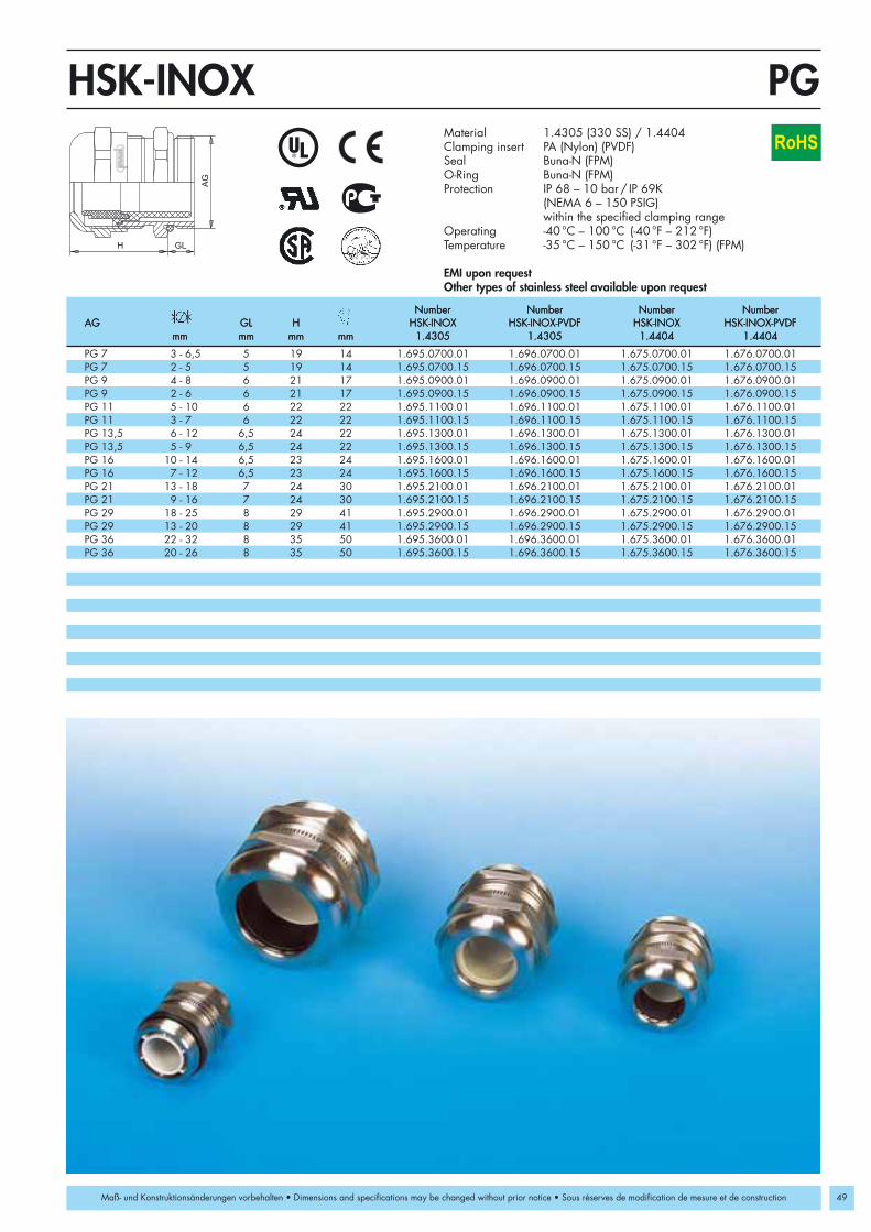
PG 7 3 - 6,5 5 19 14 1.695.0700.01 1.696.0700.01 1.675.0700.01 1.676.0700.01PG 7 2 - 5 5 19 14 1.695.0700.15 1.696.0700.15 1.675.0700.15 1.676.0700.15PG 9 4 - 8 6 21 17 1.695.0900.01 1.696.0900.01 1.675.0900.01 1.676.0900.01PG 9 2 - 6 6 21 17 1.695.0900.15 1.696.0900.15 1.675.0900.15 1.676.0900.15PG 11 5 - 10 6 22 22 1.695.1100.01 1.696.1100.01 1.675.1100.01 1.676.1100.01PG 11 3 - 7 6 22 22 1.695.1100.15 1.696.1100.15 1.675.1100.15 1.676.1100.15PG 13,5 6 - 12 6,5 24 22 1.695.1300.01 1.696.1300.01 1.675.1300.01 1.676.1300.01PG 13,5 5 - 9 6,5 24 22 1.695.1300.15 1.696.1300.15 1.675.1300.15 1.676.1300.15PG 16 10 - 14 6,5 23 24 1.695.1600.01 1.696.1600.01 1.675.1600.01 1.676.1600.01PG 16 7 - 12 6,5 23 24 1.695.1600.15 1.696.1600.15 1.675.1600.15 1.676.1600.15PG 21 13 - 18 7 24 30 1.695.2100.01 1.696.2100.01 1.675.2100.01 1.676.2100.01PG 21 9 - 16 7 24 30 1.695.2100.15 1.696.2100.15 1.675.2100.15 1.676.2100.15PG 29 18 - 25 8 29 41 1.695.2900.01 1.696.2900.01 1.675.2900.01 1.676.2900.01PG 29 13 - 20 8 29 41 1.695.2900.15 1.696.2900.15 1.675.2900.15 1.676.2900.15PG 36 22 - 32 8 35 50 1.695.3600.01 1.696.3600.01 1.675.3600.01 1.676.3600.01PG 36 20 - 26 8 35 50 1.695.3600.15 1.696.3600.15 1.675.3600.15 1.676.3600.15
H GL
AG
PGHSK-INOX
49
RoHS
Maß- und Konstruktionsänderungen vorbehalten • Dimensions and specifications may be changed without prior notice • Sous réserves de modification de mesure et de construction
Material 1.4305 (330 SS) / 1.4404Clamping insert PA (Nylon) (PVDF)Seal Buna-N (FPM)O-Ring Buna-N (FPM)Protection IP 68 – 10 bar / IP 69K
(NEMA 6 – 150 PSIG)within the specified clamping range
Operating -40 °C – 100 °C (-40 °F – 212 °F)Temperature -35 °C – 150 °C (-31 °F – 302 °F) (FPM)
EMI upon requestOther types of stainless steel available upon request
Number Number Number NumberAG GL H HSK-INOX HSK-INOX-PVDF HSK-INOX HSK-INOX-PVDF
mm mm mm mm 1.4305 1.4305 1.4404 1.4404
Number Number Number NumberAG GL H HSK-INOX HSK-INOX-PVDF HSK-INOX HSK-INOX-PVDF
mm mm mm mm 1.4305 1.4305 1.4404 1.4404
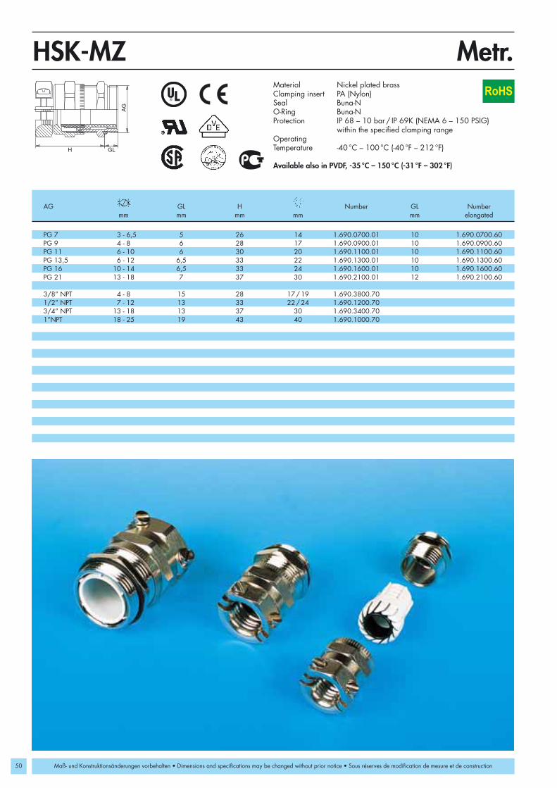
50
PG 7 3 - 6,5 5 26 14 1.690.0700.01 10 1.690.0700.60PG 9 4 - 8 6 28 17 1.690.0900.01 10 1.690.0900.60PG 11 6 - 10 6 30 20 1.690.1100.01 10 1.690.1100.60PG 13,5 6 - 12 6,5 33 22 1.690.1300.01 10 1.690.1300.60PG 16 10 - 14 6,5 33 24 1.690.1600.01 10 1.690.1600.60PG 21 13 - 18 7 37 30 1.690.2100.01 12 1.690.2100.60
3/8” NPT 4 - 8 15 28 17/19 1.690.3800.701/2” NPT 7 - 12 13 33 22/24 1.690.1200.703/4” NPT 13 - 18 13 37 30 1.690.3400.701”NPT 18 - 25 19 43 40 1.690.1000.70
AG
H GL
HSK-MZRoHS
Metr.
Maß- und Konstruktionsänderungen vorbehalten • Dimensions and specifications may be changed without prior notice • Sous réserves de modification de mesure et de construction
Material Nickel plated brassClamping insert PA (Nylon)Seal Buna-NO-Ring Buna-NProtection IP 68 – 10 bar / IP 69K (NEMA 6 – 150 PSIG)
within the specified clamping rangeOperatingTemperature -40 °C – 100 °C (-40 °F – 212 °F)
Available also in PVDF, -35 °C – 150 °C (-31 °F – 302 °F)
AG GL H Number GL Numbermm mm mm mm mm elongated

M 12 x 1,5 3 - 6,5 6,5 26 14 1.690.1200.50 10 1.690.1200.30M 16 x 1,5 6 - 8 6 28 19 1.690.1600.50M 16 x 1,5 6 - 10 6 30 20 1.690.1611.50 10 1.690.1611.30M 20 x 1,5 6 - 12 6 33 22 1.690.2000.50M 20 x 1,5 10 - 14 6 33 24 1.690.2016.50 10 1.690.2016.30M 25 x 1,5 13 - 18 7 37 30 1.690.2500.50 12 1.690.2500.30M 32 x 1,5 18 - 25 8 43 40 1.690.3200.50 12 1.690.3200.30M 40 x 1,5 22 - 32 8 50 50 1.690.4000.50 15 1.690.4000.30M 50 x 1,5 32 - 38 9 51 57 1.690.5000.50M 50 x 1,5 25 - 31 9 51 57 1.690.5000.51M 63 x 1,5 37 - 44 10 52 64/68 1.690.6300.50M 63 x 1,5 29 - 35 10 52 64/68 1.690.6300.51
PG 7 3 - 6,5 5 26 14 1.690.0700.01 10 1.690.0700.60PG 9 4 - 8 6 28 17 1.690.0900.01 10 1.690.0900.60PG 11 6 - 10 6 30 20 1.690.1100.01 10 1.690.1100.60PG 13,5 6 - 12 6,5 33 22 1.690.1300.01 10 1.690.1300.60PG 16 10 - 14 6,5 33 24 1.690.1600.01 10 1.690.1600.60PG 21 13 - 18 7 37 30 1.690.2100.01 12 1.690.2100.60
3/8” NPT 4 - 8 15 28 17/19 1.690.3800.701/2” NPT 7 - 12 13 33 22/24 1.690.1200.703/4” NPT 13 - 18 13 37 30 1.690.3400.701”NPT 18 - 25 19 43 40 1.690.1000.70
AG
H GL
HSK-MZ
51
PG/NPTRoHS
Maß- und Konstruktionsänderungen vorbehalten • Dimensions and specifications may be changed without prior notice • Sous réserves de modification de mesure et de construction
Material Nickel plated brassClamping insert PA (Nylon)Seal Buna-NO-Ring Buna-NProtection IP 68 – 10 bar / IP 69K (NEMA 6 – 150 PSIG)
within the specified clamping rangeOperatingTemperature -40 °C – 100 °C (-40 °F – 212 °F)
Available also in PVDF, -35 °C – 150 °C (-31 °F – 302 °F)
AG GL H Number GL Numbermm mm mm mm mm elongated
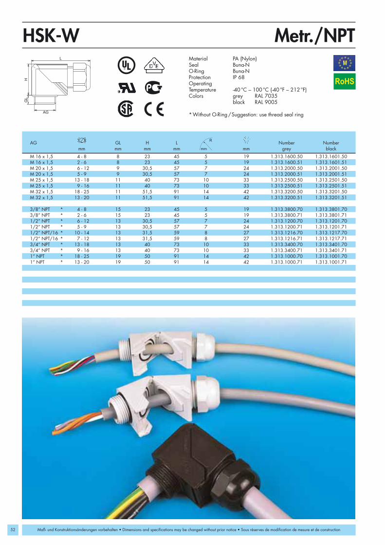
52
M 16 x 1,5 4 - 8 8 23 45 5 19 1.313.1600.50 1.313.1601.50M 16 x 1,5 2 - 6 8 23 45 5 19 1.313.1600.51 1.313.1601.51M 20 x 1,5 6 - 12 9 30,5 57 7 24 1.313.2000.50 1.313.2001.50M 20 x 1,5 5 - 9 9 30,5 57 7 24 1.313.2000.51 1.313.2001.51M 25 x 1,5 13 - 18 11 40 73 10 33 1.313.2500.50 1.313.2501.50M 25 x 1,5 9 - 16 11 40 73 10 33 1.313.2500.51 1.313.2501.51M 32 x 1,5 18 - 25 11 51,5 91 14 42 1.313.3200.50 1.313.3201.50M 32 x 1,5 13 - 20 11 51,5 91 14 42 1.313.3200.51 1.313.3201.51
3/8” NPT * 4 - 8 15 23 45 5 19 1.313.3800.70 1.313.3801.703/8” NPT * 2 - 6 15 23 45 5 19 1.313.3800.71 1.313.3801.711/2” NPT * 6 - 12 13 30,5 57 7 24 1.313.1200.70 1.313.1201.701/2” NPT * 5 - 9 13 30,5 57 7 24 1.313.1200.71 1.313.1201.711/2” NPT/16 * 10 - 14 13 31,5 59 8 27 1.313.1216.70 1.313.1217.701/2” NPT/16 * 7 - 12 13 31,5 59 8 27 1.313.1216.71 1.313.1217.713/4” NPT * 13 - 18 13 40 73 10 33 1.313.3400.70 1.313.3401.703/4” NPT * 9 - 16 13 40 73 10 33 1.313.3400.71 1.313.3401.711” NPT * 18 - 25 19 50 91 14 42 1.313.1000.70 1.313.1001.701” NPT * 13 - 20 19 50 91 14 42 1.313.1000.71 1.313.1001.71
AG
H
L
GL
Metr./NPTHSK-WM
RoHS
Maß- und Konstruktionsänderungen vorbehalten • Dimensions and specifications may be changed without prior notice • Sous réserves de modification de mesure et de construction
Material PA (Nylon)Seal Buna-NO-Ring Buna-NProtection IP 68OperatingTemperature -40 °C – 100 °C (-40 °F – 212 °F)Colors grey RAL 7035
black RAL 9005
*Without O-Ring/Suggestion: use thread seal ring
AG GL H L Number Numbermm mm mm mm mm grey black

10 - 14 29 66 7 25 1.309.2000.507 - 12 29 66 7 25 1.309.2000.51
M 20 x 1,5 10 - 14 6 37 66 7 25 1.309.2020.50 7 - 12 6 37 66 7 25 1.309.2020.51
PG 13,5 10 - 14 6 37 66 7 25 1.309.2013.507 - 12 6 37 66 7 25 1.309.2013.51
Metr./PGHSK-M-WM
19,8
ø3,2
19
,8
53
min. 1 x 45°
M 20 x 1,5 / PG 13,5
RoHS
Maß- und Konstruktionsänderungen vorbehalten • Dimensions and specifications may be changed without prior notice • Sous réserves de modification de mesure et de construction
With mounting flange
With threaded connection
M40 x 1,5 upon request
Material Zinc die casting/Nickel plated brassClamping insert PA (Nylon)Seal ring Buna-NProtection IP 68OperatingTemperature -40 °C – 100 °C (-40 °F – 212 °F)
AG GL H L Numbermm mm mm mm mm
25 F
lang
e w
idth
Ø 3
3,5

54
PG 9 4 - 8 8 23 45 5 19 1.313.0900.14 1.313.0901.14PG 9 2 - 6 8 23 45 5 19 1.313.0900.15 1.313.0901.15PG 11 5 - 10 8 27 50 6 22 1.313.1100.14 1.313.1101.14PG 11 3 - 7 8 27 50 6 22 1.313.1100.15 1.313.1101.15PG 13,5 6 - 12 9 30,5 57 7 24 1.313.1300.14 1.313.1301.14PG 13,5 5 - 9 9 30,5 57 7 24 1.313.1300.15 1.313.1301.15PG 16 10 - 14 10 32,5 59 8 27 1.313.1600.14 1.313.1601.14PG 16 7 - 12 10 32,5 59 8 27 1.313.1600.15 1.313.1601.15PG 21 13 - 18 11 40 73 10 33 1.313.2100.14 1.313.2101.14PG 21 9 - 16 11 40 73 10 33 1.313.2100.15 1.313.2101.15PG 29 18 - 25 11 51,5 91 14 42 1.313.2900.14 1.313.2901.14PG 29 13 - 20 11 51,5 91 14 42 1.313.2900.15 1.313.2901.15
PG 9 4 - 8 8 28 45 5 19 1.317.0900.14 1.317.0901.14PG 9 2 - 6 8 28 45 5 19 1.317.0900.15 1.317.0901.15PG 11 5 - 10 8 32 50 6 22 1.317.1100.14 1.317.1101.14PG 11 3 - 7 8 32 50 6 22 1.317.1100.15 1.317.1101.15PG 13 6 - 12 9 35,5 57 7 24 1.317.1300.14 1.317.1301.14PG 13 5 - 9 9 35,5 57 7 24 1.317.1300.15 1.317.1301.15PG 16 10 - 14 10 38,5 59 8 27 1.317.1600.14 1.317.1601.14PG 16 7 - 12 11 46 73 10 33 1.317.1600.15 1.317.1601.15PG 21 13 - 18 11 46 73 10 33 1.317.2100.14 1.317.2101.14PG 21 9 - 16 11 46 73 10 33 1.317.2100.15 1.317.2101.15
AG
H
L
GL
PGHSK-WRoHS
Maß- und Konstruktionsänderungen vorbehalten • Dimensions and specifications may be changed without prior notice • Sous réserves de modification de mesure et de construction
Swivel version
Material PA (Nylon) Seal Buna-NO-Ring Buna-NProtection IP 68OperatingTemperature -40 °C – 100 °C (-40 °F – 212 °F)Colors grey RAL 7035
black RAL 9005
AG GL H L Number Numbermm mm mm mm mm grey black
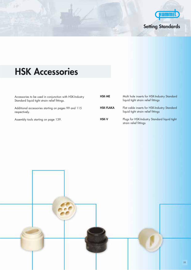
55
HSK Accessories
Accessories to be used in conjunction with HSK-IndustryStandard liquid tight strain relief fittings.
Additional accessories starting on pages 99 and 115respectively.
Assembly tools starting on page 139.
Setting Standards
HSK-ME Multi hole inserts for HSK-Industry Standardliquid tight strain relief fittings
HSK-FLAKA Flat cable inserts for HSK-Industry Standardliquid tight strain relief fittings
HSK-V Plugs for HSK-Industry Standard liquid tightstrain relief fittings
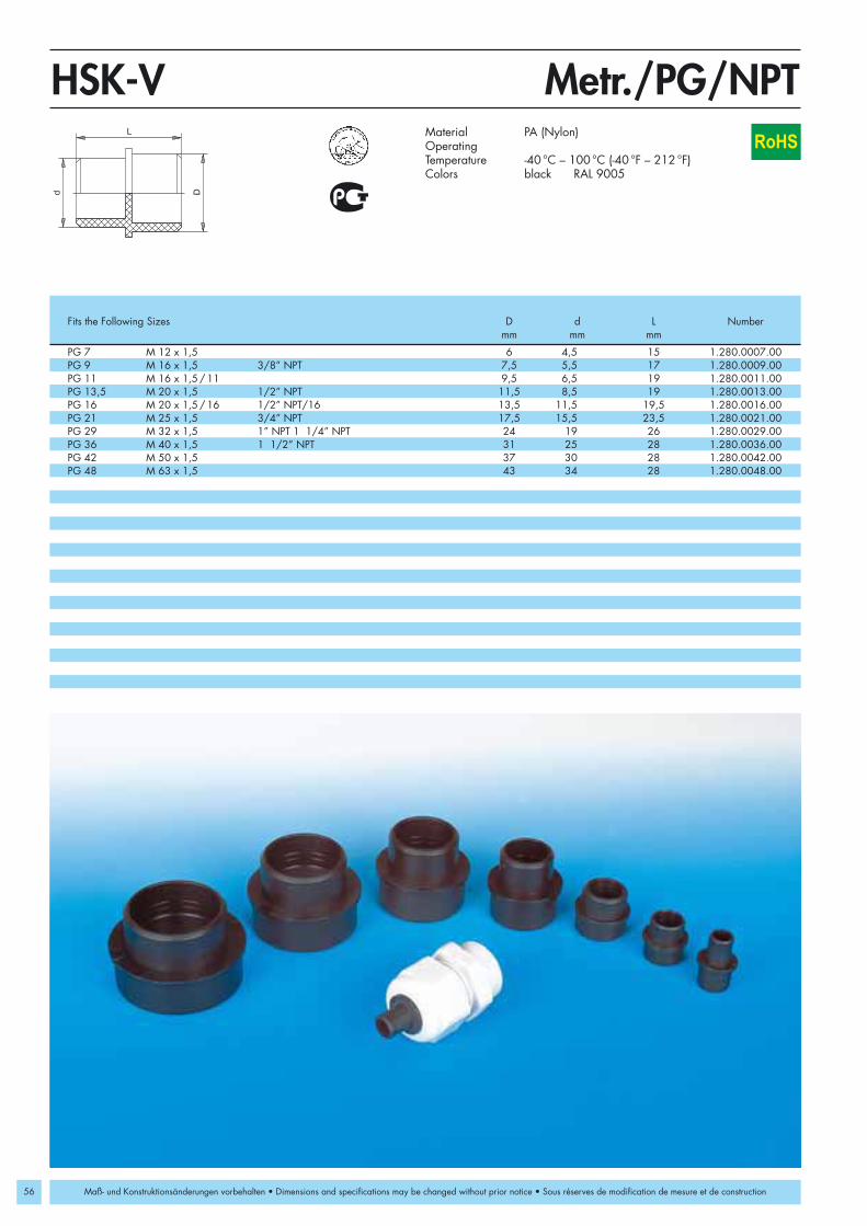
56
d D
L
HSK-V
PG 7 M 12 x 1,5 6 4,5 15 1.280.0007.00PG 9 M 16 x 1,5 3/8” NPT 7,5 5,5 17 1.280.0009.00PG 11 M 16 x 1,5/11 9,5 6,5 19 1.280.0011.00PG 13,5 M 20 x 1,5 1/2” NPT 11,5 8,5 19 1.280.0013.00PG 16 M 20 x 1,5/16 1/2” NPT/16 13,5 11,5 19,5 1.280.0016.00PG 21 M 25 x 1,5 3/4” NPT 17,5 15,5 23,5 1.280.0021.00PG 29 M 32 x 1,5 1” NPT 1 1/4” NPT 24 19 26 1.280.0029.00PG 36 M 40 x 1,5 1 1/2” NPT 31 25 28 1.280.0036.00PG 42 M 50 x 1,5 37 30 28 1.280.0042.00PG 48 M 63 x 1,5 43 34 28 1.280.0048.00
Metr./PG/NPTRoHS
Material PA (Nylon)OperatingTemperature -40 °C – 100 °C (-40 °F – 212 °F)Colors black RAL 9005
Fits the Following Sizes D d L Numbermm mm mm
Maß- und Konstruktionsänderungen vorbehalten • Dimensions and specifications may be changed without prior notice • Sous réserves de modification de mesure et de construction

57
PG 7 /KR PG 9 1.089.0799.19PG 9 /KE PG 7 /KR PG 11 M 16 x 1,5 3/8" NPT 4 x 1,4 1.089.0900.19 2 x 3 1.089.0901.19 1.089.0999.19PG 9 /KE PG 7 /KR PG 11 M 16 x 1,5 3/8" NPT 5 x 1,6 1.089.0902.19 10 x 1,4 1.089.0904.19PG 11/KE PG 9 /KR PG 13,5 2 x 3 1.089.1100.19 3 x 3 1.089.1101.19 1.089.1199.19PG 11/KE PG 9 /KR PG 13,5 2 x 4 1.089.1102.19 3 x 1,5 1.089.1103.19PG 13,5/KE PG 11/KR PG 16 M 20 x 1,5 1/2" NPT 3 x 2 1.089.1300.19 6 x 3 1.089.1301.19 1.089.1399.19PG 13,5/KE PG 11/KR PG 16 M 20 x 1,5 1/2" NPT 3 x 4 1.089.1302.19 2 x 5 1.089.1303.19PG 16/KE PG 13,5/KR PG 21 1/2" NPT/16 4 x 4 1.089.1602.19 5 x 4 1.089.1603.19PG 16/KE PG 13,5/KR PG 21 1/2" NPT/16 6 x 4 1.089.1604.19 2 x 6 1.089.1605.19PG 21/KE PG 16 M 25 x 1,5 3/4" NPT 4 x 6 1.089.2100.19 3 x 7 1.089.2101.19 1.089.2199.19PG 21/KE PG 16 M 25 x 1,5 3/4" NPT 2 x 8 1.089.2102.19 4 x 5 1.089.2103.19PG 29 M 32 x 1,5 1" NPT/1 1/4" NPT 6 x 6,5 1.089.2900.19 4 x 9 1.089.2901.19 1.089.2999.19PG 36 M 40 x 1,5 1 1/2" NPT 5 x 9 1.089.3600.19 7 x 9 1.089.3601.19 1.089.3699.19PG 36 M 40 x 1,5 1 1/2" NPT 6 x 8 1.089.3602.19 2 x 15 1.089.3603.19PG 42 M 50 x 1,5 1.089.4299.19PG 48 M 63 x 1,5 8 x 10 1.089.4800.19 6 x 12 1.089.4801.19 1.089.4899.19
Metr./PG/NPTHSK-MEd RoHS
Maß- und Konstruktionsänderungen vorbehalten • Dimensions and specifications may be changed without prior notice • Sous réserves de modification de mesure et de construction
Material ElastomerOperatingTemperature -40 °C – 100 °C (-40 °F – 212 °F)
These inserts are examples, other inserts available upon requestInstallation instructions see page 162
This inserts can be used in cable glands of the HSK-series
Other materials available upon request
Number Number NumberFits the Following Sizes of Holes Number of Holes Number Without
x d x d Holes

58
Metr./PG/NPTHSK-FLAKAb
l l
b
l
b
PG 13 (ASI-BUS) M 20 x 1,5 1/2" NPT 4,2 x 10,4 1.091.1300.19PG 16/KE PG 13,5/KR PG 21 1/2" NPT/16 6 x 14 1.091.1600.19 5 x 11,5 1.091.1601.19PG 16/KE PG 13,5/KR PG 21 1/2" NPT/16 7 x 12 1.091.1602.19PG 21/KE PG 16 M 25 x 1,5 3/4" NPT 6 x 14 1.091.2100.19 7 x 14 1.091.2101.19PG 29 M 32 x 1,5 1" NPT/1 1/4" NPT 8 x 22 1.091.2900.19PG 36 M 40 x 1,5 1 1/2" NPT 10 x 28,5 1.091.3600.19 5,5 x 29 1.091.3601.19PG 42 M 50 x 1,5 11,5 x 33,5 1.091.4200.19PG 48 M 63 x 1,5 12 x 38 1.091.4800.19
ASI-BUS
RoHS
Maß- und Konstruktionsänderungen vorbehalten • Dimensions and specifications may be changed without prior notice • Sous réserves de modification de mesure et de construction
Material ElastomerOperatingTemperature -40 °C – 100 °C (-40 °F – 212 °F)
These inserts are examples, other inserts available upon requestInstallation instructions see page 162
This inserts can be used in cable glands of the HSK-series
Other materials available upon request
Fits the Following Sizes Dimensions Number Dimensions Numberb x l b x l

59
Strain relief fittings in all popular thread types and sizes forstandard applications in the following areas:
• Machine, apparatus and plant equipment• Measuring control and feedback systems• Medical equipment• Railroad cars and vehicles• Power plants (hydro, gas, coal or wind)• Industrial installations
and in all applications where excellent performance, fireresistance, and resistance against turning of the cable arecritical.
HSK-Flex Liquid tight strain relief fittings with flexprotection made of nylon 6/6
HSK-M-Flex Liquid tight strain relief fittings with stainlesssteel flex protection
HSK-W-Flex Liquid tight strain relief fitting 90° snap elbowwith flex protection made of nylon 6/6
Setting Standards
HSK-Flex Standard

60
AG
GLH
d
Metr.HSK-FlexEN50262
M 12 x 1,5 3 - 6,5 8 54 7 15 1.293.1200.50 1.293.1201.50 15 1.293.1200.30 1.293.1201.30M 12 x 1,5 2 - 5 8 54 7 15 1.293.1200.51 1.293.1201.51 15 1.293.1200.31 1.293.1201.31M 16 x 1,5 4 - 8 8 63 8,5 19 1.293.1600.50 1.293.1601.50 15 1.293.1600.30 1.293.1601.30M 16 x 1,5 2 - 6 8 63 8,5 19 1.293.1600.51 1.293.1601.51 15 1.293.1600.31 1.293.1601.31M 16 x 1,5 5 - 10 8 78 10,5 22 1.294.1600.50 1.294.1601.50 15 1.294.1600.30 1.294.1601.30M 16 x 1,5 3 - 7 8 78 10,5 22 1.294.1600.51 1.294.1601.51 15 1.294.1600.31 1.294.1601.31M 20 x 1,5 6 - 12 9 90 13 24 1.293.2000.50 1.293.2001.50 15 1.293.2000.30 1.293.2001.30M 20 x 1,5 5 - 9 9 90 13 24 1.293.2000.51 1.293.2001.51 15 1.293.2000.31 1.293.2001.31M 20 x 1,5 10 - 14 9 100 15,5 27 1.294.2000.50 1.294.2001.50 15 1.294.2000.30 1.294.2001.30M 20 x 1,5 7 - 12 9 100 15,5 27 1.294.2000.51 1.294.2001.51 15 1.294.2000.31 1.294.2001.31M 25 x 1,5 13 - 18 11 114 20 33 1.293.2500.50 1.293.2501.50 15 1.293.2500.30 1.293.2501.30M 25 x 1,5 9 -16 11 114 20 33 1.293.2500.51 1.293.2501.51 15 1.293.2500.31 1.293.2501.31
RoHS
Maß- und Konstruktionsänderungen vorbehalten • Dimensions and specifications may be changed without prior notice • Sous réserves de modification de mesure et de construction
Material PA (Nylon)Seal Buna-NProtection IP 68 – 10 bar / IP 69K
(NEMA 6 -150 PSIG)within the specified clamping range only with optional O-Ring (see page 132)
OperatingTemperature -40 °C – 100 °C (-40 °F – 212 °F)Colors grey RAL 7035
black RAL 9005
Number NumberAG GL H d Number Number GL grey black
mm mm mm mm mm grey black mm elongated elongated

M 12 x 1,5 3 - 6,5 6,5 5,5 6,8 14 1.623.1200.50 10 1.623.1200.30M 12 x 1,5 2 - 5 6,5 55 6,8 14 1.623.1200.51 10 1.623.1200.31M 16 x 1,5 4 -8 6 66 8,2 19 1.623.1600.50M 16 x 1,5 2 - 6 6 66 8,2 19 1.623.1600.51M 16 x 1,5 5 - 10 6 77 10,3 20 1.623.1611.50 10 1.623.1611.30M 16 x 1,5 3 - 7 6 77 10,3 20 1.623.1611.51 10 1.623.1611.31M 20 x 1,5 6 - 12 6 88 12,3 22 1.623.2000.50M 20 x 1,5 5 - 9 6 88 12,3 22 1.623.2000.51M 20 x 1,5 10 - 14 6 98 14,3 24 1.623.2016.50 10 1.623.2016.30M 20 x 1,5 7 - 12 6 98 14,3 24 1.623.2016.51 10 1.623.2016.31M 25 x 1,5 13 - 18 7 111 18,4 30 1.623.2500.50 12 1.623.2500.30M 25 x 1,5 9 - 16 7 111 18,4 30 1.623.2500.51 12 1.623.2500.31
AG
GLH
d
Metr.HSK-M-FlexEN50262
61
RoHS
Maß- und Konstruktionsänderungen vorbehalten • Dimensions and specifications may be changed without prior notice • Sous réserves de modification de mesure et de construction
Material Nickel plated brassSteel spring 1.4310Clamping insert PA (Nylon)Seal Buna-NO-Ring Buna-NProtection IP 68 – 10 bar / IP 69K
(NEMA 6 – 150 PSIG)within the specified clamping range
OperatingTemperature -40 °C – 100 °C (-40 °F – 212 °F)
AG GL H d Number GL Numbermm mm mm mm mm mm elongated
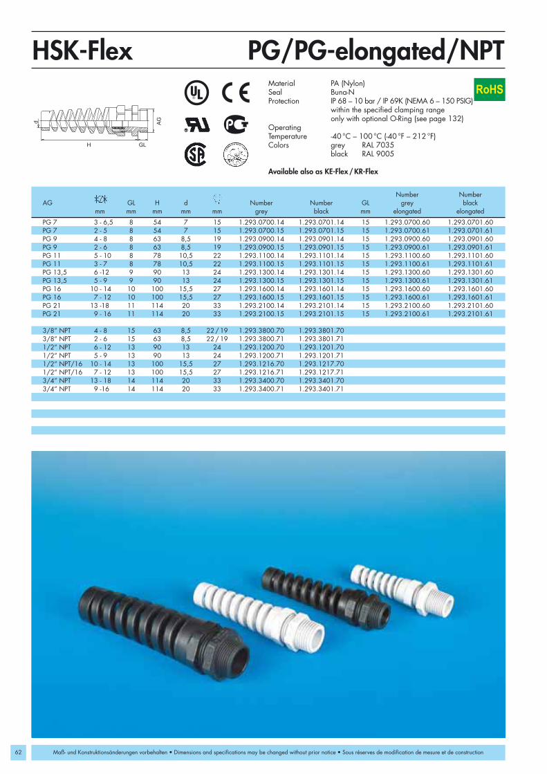
62
PG 7 3 - 6,5 8 54 7 15 1.293.0700.14 1.293.0701.14 15 1.293.0700.60 1.293.0701.60PG 7 2 - 5 8 54 7 15 1.293.0700.15 1.293.0701.15 15 1.293.0700.61 1.293.0701.61PG 9 4 - 8 8 63 8,5 19 1.293.0900.14 1.293.0901.14 15 1.293.0900.60 1.293.0901.60PG 9 2 - 6 8 63 8,5 19 1.293.0900.15 1.293.0901.15 15 1.293.0900.61 1.293.0901.61PG 11 5 - 10 8 78 10,5 22 1.293.1100.14 1.293.1101.14 15 1.293.1100.60 1.293.1101.60PG 11 3 - 7 8 78 10,5 22 1.293.1100.15 1.293.1101.15 15 1.293.1100.61 1.293.1101.61PG 13,5 6 -12 9 90 13 24 1.293.1300.14 1.293.1301.14 15 1.293.1300.60 1.293.1301.60PG 13,5 5 - 9 9 90 13 24 1.293.1300.15 1.293.1301.15 15 1.293.1300.61 1.293.1301.61PG 16 10 - 14 10 100 15,5 27 1.293.1600.14 1.293.1601.14 15 1.293.1600.60 1.293.1601.60PG 16 7 - 12 10 100 15,5 27 1.293.1600.15 1.293.1601.15 15 1.293.1600.61 1.293.1601.61PG 21 13 -18 11 114 20 33 1.293.2100.14 1.293.2101.14 15 1.293.2100.60 1.293.2101.60PG 21 9 - 16 11 114 20 33 1.293.2100.15 1.293.2101.15 15 1.293.2100.61 1.293.2101.61
3/8” NPT 4 - 8 15 63 8,5 22/19 1.293.3800.70 1.293.3801.703/8” NPT 2 - 6 15 63 8,5 22/19 1.293.3800.71 1.293.3801.711/2” NPT 6 - 12 13 90 13 24 1.293.1200.70 1.293.1201.701/2” NPT 5 - 9 13 90 13 24 1.293.1200.71 1.293.1201.711/2” NPT/16 10 - 14 13 100 15,5 27 1.293.1216.70 1.293.1217.701/2” NPT/16 7 - 12 13 100 15,5 27 1.293.1216.71 1.293.1217.713/4” NPT 13 - 18 14 114 20 33 1.293.3400.70 1.293.3401.703/4” NPT 9 -16 14 114 20 33 1.293.3400.71 1.293.3401.71
AG
GLH
d
HSK-FlexRoHS
Maß- und Konstruktionsänderungen vorbehalten • Dimensions and specifications may be changed without prior notice • Sous réserves de modification de mesure et de construction
PG/PG-elongated/NPTMaterial PA (Nylon) Seal Buna-NProtection IP 68 – 10 bar / IP 69K (NEMA 6 – 150 PSIG)
within the specified clamping rangeonly with optional O-Ring (see page 132)
OperatingTemperature -40 °C – 100 °C (-40 °F – 212 °F)Colors grey RAL 7035
black RAL 9005
Available also as KE-Flex/KR-Flex
Number NumberAG GL H d Number Number GL grey black
mm mm mm mm mm grey black mm elongated elongated

PG 7 3 - 6,5 5 55 6,8 14 1.623.0700.01 10 1.623.0700.60PG 7 2 - 5 5 55 6,8 14 1.623.0700.15 10 1.623.0700.61PG 9 4 - 8 6 66 8,2 17 1.623.0900.01 10 1.623.0900.60PG 9 2 - 6 6 66 8,2 17 1.623.0900.15 10 1.623.0900.61PG 11 5 - 10 6 77 10,3 20 1.623.1100.01 10 1.623.1100.60PG 11 3 - 7 6 77 10,3 20 1.623.1100.15 10 1.623.1100.61PG 13,5 6 - 12 6,5 88 12,3 22 1.623.1300.01 10 1.623.1300.60PG 13,5 5 - 9 6,5 88 12,3 22 1.623.1300.15 10 1.623.1300.61PG 16 10 - 14 6,5 98 14,3 24 1.623.1600.01 10 1.623.1600.60PG 16 7 - 12 6,5 98 14,3 24 1.623.1600.15 10 1.623.1600.61PG 21 13 - 18 7 111 18,4 30 1.623.2100.01 12 1.623.2100.60PG 21 9 - 16 7 111 18,4 30 1.623.2100.15 12 1.623.2100.61
NPT 3/8” 4 - 8 15 66 8,2 17/19 1.623.3800.70NPT 3/8” 2 - 6 15 66 8,2 17/19 1.623.3800.71NPT 1/2” 6 - 12 13 88 12,3 22/24 1.623.1200.70NPT 1/2” 5 - 9 13 88 12,3 22/24 1.623.1200.71NPT 3/4” 13 - 18 13 111 18,4 33 1.623.3400.70NPT 3/4” 9 - 16 13 111 18,4 33 1.623.3400.71
AG
GLH
d
HSK-M-Flex
63
RoHS
Maß- und Konstruktionsänderungen vorbehalten • Dimensions and specifications may be changed without prior notice • Sous réserves de modification de mesure et de construction
PG/PG-elongated/NPTMaterial Nickel plated brassSteel spring 1.4310Clamping insert PA (Nylon)Seal Buna-NO-Ring Buna-NProtection IP 68 – 10 bar / IP 69K
(150 PSIG) NEMA 4x and 6 within the specified clamping range
OperatingTemperature -40 °C – 100 °C (-40 °F – 212 °F)
AG GL H d Number GL Numbermm mm mm mm mm mm elongated

64
M 16 x 1,5 4 - 8 8,5 8 23 85 5 19 1.314.1600.50 1.314.1601.50M 16 x 1,5 2 - 6 8,5 8 23 85 5 19 1.314.1600.51 1.314.1601.51M 20 x 1,5 6 - 12 13 9 30,5 119 7 24 1.314.2000.50 1.314.2001.50M 20 x 1,5 5 - 9 13 9 30,5 119 7 24 1.314.2000.51 1.314.2001.51M 25 x 1,5 13 - 18 20 11 40 156 10 33 1.314.2500.50 1.314.2501.50M 25 x 1,5 9 - 16 20 11 40 156 10 33 1.314.2500.51 1.314.2501.51
PG 9 4 - 8 8,5 8 23 85 5 19 1.314.0900.14 1.314.0901.14PG 9 2 - 6 8,5 8 23 85 5 19 1.314.0900.15 1.314.0901.15PG 11 5 - 10 10,5 8 27 103 6 22 1.314.1100.14 1.314.1101.14PG 11 3 - 7 10,5 8 27 103 6 22 1.314.1100.15 1.314.1101.15PG 13,5 6 - 12 13 9 30,5 119 7 24 1.314.1300.14 1.314.1301.14PG 13,5 5 - 9 13 9 30,5 119 7 24 1.314.1300.15 1.314.1301.15PG 16 10 - 14 15,5 10 32,5 130 8 27 1.314.1600.14 1.314.1601.14PG 16 7 - 12 15,5 10 32,5 130 8 27 1.314.1600.15 1.314.1601.15PG 21 13 - 18 20 11 40 156 10 33 1.314.2100.14 1.314.2101.14PG 21 9 - 16 20 11 40 156 10 33 1.314.2100.15 1.314.2101.15
3/8” NPT * 4 - 8 8,5 15 23 85 5 19 1.314.3800.70 1.314.3801.703/8” NPT * 2 - 6 8,5 15 23 85 5 19 1.314.3800.71 1.314.3801.711/2” NPT * 6 - 12 13 13 30,5 119 7 24 1.314.1200.70 1.314.1201.701/2” NPT * 5 - 9 13 13 30,5 119 7 24 1.314.1200.71 1.314.1201.711/2” NPT /16 * 10 - 14 15,5 13 31,5 130 8 27 1.314.1216.70 1.314.1217.701/2” NPT /16 * 7 - 12 15,5 13 31,5 130 8 27 1.314.1216.71 1.314.1217.713/4” NPT * 13 - 18 20 13 40 156 10 33 1.314.3400.70 1.314.3401.703/4” NPT * 9 - 16 20 13 40 156 10 33 1.314.3400.71 1.314.3401.71
AG
GL
H
L
d
Metr./PG/NPTHSK-W-FlexEN50262
RoHS
Maß- und Konstruktionsänderungen vorbehalten • Dimensions and specifications may be changed without prior notice • Sous réserves de modification de mesure et de construction
Material PA (Nylon)Seal Buna-NO-Ring Buna-NProtection IP 68OperatingTemperature -40 °C – 100 °C (-40 °F – 212 °F)Colors grey RAL 7035
black RAL 9005
*Without O-Ring/suggestion: Thread Seal Ring
AG d GL H L Number Numbermm mm mm mm mm mm grey black

65
ATEX
HSK-M-EMV-Ex EMI compatible standard strain relieffittings for hazardous locations
HSK-M-EMV-PVDF-Ex EMI compatible standard strain relieffittings for hazardous locations usedin chemical and high temperatureapplications
HSK-M-EMV-D-Ex EMI compatible standard strain relieffittings for hazardous locations withfeed-through suitable for cables withbraided and foil shield
HSK-MZ-EMV-Ex EMI compatible standard strain relief fittings for hazardous locations withadditional cable clamp for flex protec-tion
HSK-MZ-EMV-PVDF-Ex EMI compatible standard strain relief fittings for chemical and high tempera-ture applications with additional cableclamp for flex protection
Setting Standards
Strain relief fittings in all popular thread types and sizes for areliable low-ohm shield used for electrical equipment in hazar-dous locations with protection „e” according to EN 50014 andEN 50019:
• Machine, apparatus and plant equipment.• Measuring, control and feedback systems• Control panels• Railroad cars and vehicles• Power plants (hydro, gas, coal or wind)
Also used in all areas where besides a reliable seal, high pull-out resistance and anti-rotation provisions, a dependablecontact with the cable shield is required.
HSK-EMV-Ex Standard
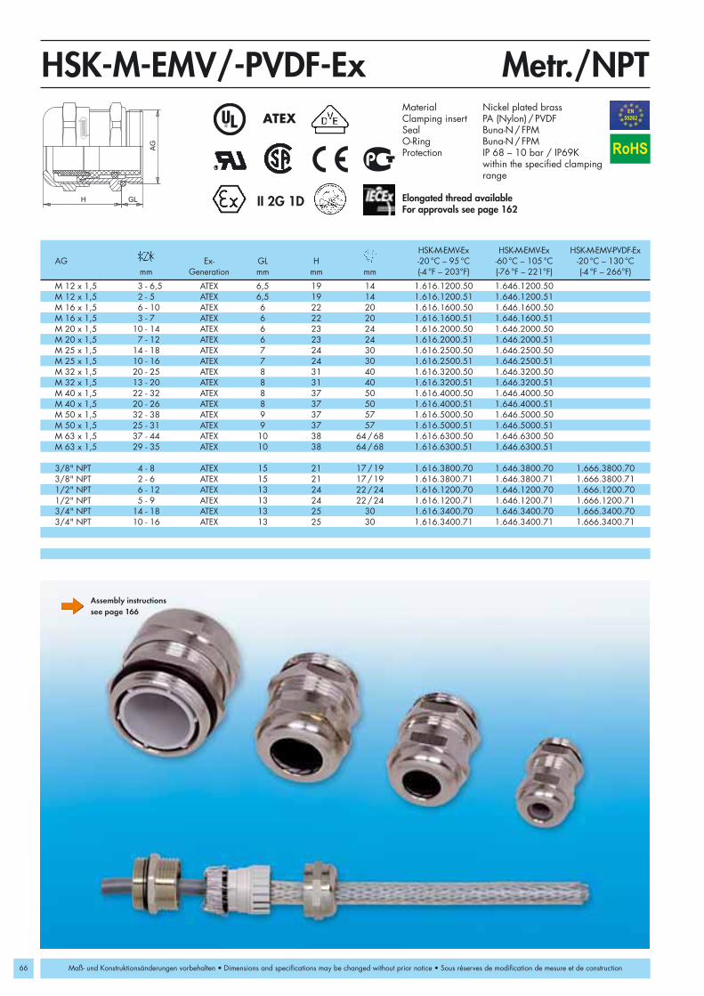
66
M 12 x 1,5 3 - 6,5 ATEX 6,5 19 14 1.616.1200.50 1.646.1200.50M 12 x 1,5 2 - 5 ATEX 6,5 19 14 1.616.1200.51 1.646.1200.51M 16 x 1,5 6 - 10 ATEX 6 22 20 1.616.1600.50 1.646.1600.50M 16 x 1,5 3 - 7 ATEX 6 22 20 1.616.1600.51 1.646.1600.51M 20 x 1,5 10 - 14 ATEX 6 23 24 1.616.2000.50 1.646.2000.50M 20 x 1,5 7 - 12 ATEX 6 23 24 1.616.2000.51 1.646.2000.51M 25 x 1,5 14 - 18 ATEX 7 24 30 1.616.2500.50 1.646.2500.50M 25 x 1,5 10 - 16 ATEX 7 24 30 1.616.2500.51 1.646.2500.51M 32 x 1,5 20 - 25 ATEX 8 31 40 1.616.3200.50 1.646.3200.50M 32 x 1,5 13 - 20 ATEX 8 31 40 1.616.3200.51 1.646.3200.51M 40 x 1,5 22 - 32 ATEX 8 37 50 1.616.4000.50 1.646.4000.50M 40 x 1,5 20 - 26 ATEX 8 37 50 1.616.4000.51 1.646.4000.51M 50 x 1,5 32 - 38 ATEX 9 37 57 1.616.5000.50 1.646.5000.50M 50 x 1,5 25 - 31 ATEX 9 37 57 1.616.5000.51 1.646.5000.51M 63 x 1,5 37 - 44 ATEX 10 38 64/68 1.616.6300.50 1.646.6300.50M 63 x 1,5 29 - 35 ATEX 10 38 64/68 1.616.6300.51 1.646.6300.51
3/8" NPT 4 - 8 ATEX 15 21 17/19 1.616.3800.70 1.646.3800.70 1.666.3800.703/8" NPT 2 - 6 ATEX 15 21 17/19 1.616.3800.71 1.646.3800.71 1.666.3800.711/2" NPT 6 - 12 ATEX 13 24 22/24 1.616.1200.70 1.646.1200.70 1.666.1200.701/2" NPT 5 - 9 ATEX 13 24 22/24 1.616.1200.71 1.646.1200.71 1.666.1200.713/4" NPT 14 - 18 ATEX 13 25 30 1.616.3400.70 1.646.3400.70 1.666.3400.703/4" NPT 10 - 16 ATEX 13 25 30 1.616.3400.71 1.646.3400.71 1.666.3400.71
AG
H GL
Metr./NPTHSK-M-EMV/-PVDF-ExEN50262ATEX
II 2G 1D
RoHS
Maß- und Konstruktionsänderungen vorbehalten • Dimensions and specifications may be changed without prior notice • Sous réserves de modification de mesure et de construction
Assembly instructionssee page 166
HSK-M-EMV-Ex HSK-M-EMV-Ex HSK-M-EMV-PVDF-ExAG Ex- GL H -20 °C – 95 °C -60 °C – 105 °C -20 °C – 130 °C
mm Generation mm mm mm (-4 °F – 203°F) (-76 °F – 221°F) (-4 °F – 266°F)
Material Nickel plated brassClamping insert PA (Nylon) / PVDFSeal Buna-N/FPMO-Ring Buna-N/FPMProtection IP 68 – 10 bar / IP69K
within the specified clamping range
Elongated thread available For approvals see page 162

PG 7 3 - 6,5 ATEX 5 19 14 1.616.0700.01 1.646.0700.01 1.666.0700.01PG 7 2 - 5 ATEX 5 19 14 1.616.0700.15 1.646.0700.15 1.666.0700.15PG 9 4 - 8 ATEX 6 21 17 1.616.0900.01 1.646.0900.01 1.666.0900.01PG 9 2 - 6 ATEX 6 21 17 1.616.0900.15 1.646.0900.15 1.666.0900.15PG 11 6 - 10 ATEX 6 22 20 1.616.1100.01 1.646.1100.01 1.666.1100.01PG 11 3 - 7 ATEX 6 22 20 1.616.1100.15 1.646.1100.15 1.666.1100.15PG 13,5 6 - 12 ATEX 6,5 24 22 1.616.1300.01 1.646.1300.01 1.666.1300.01PG 13,5 5 - 9 ATEX 6,5 24 22 1.616.1300.15 1.646.1300.15 1.666.1300.15PG 16 10 - 14 ATEX 6,5 23 24 1.616.1600.01 1.646.1600.01 1.666.1600.01PG 16 7 - 12 ATEX 6,5 23 24 1.616.1600.15 1.646.1600.15 1.666.1600.15PG 21 14 - 18 ATEX 7 24 30 1.616.2100.01 1.646.2100.01 1.666.2100.01PG 21 10 - 16 ATEX 7 24 30 1.616.2100.15 1.646.2100.15 1.666.2100.15PG 29 20 - 25 ATEX 8 29 40 1.616.2900.01 1.646.2900.01 1.666.2900.01PG 29 13 - 20 ATEX 8 29 40 1.616.2900.15 1.646.2900.15 1.666.2900.15PG 36 22 - 32 ATEX 8 35 50 1.616.3600.01 1.646.3600.01 1.666.3600.01PG 36 20 - 26 ATEX 8 35 50 1.616.3600.15 1.646.3600.15 1.666.3600.15PG 42 32 - 38 ATEX 9 37 57 1.616.4200.01 1.646.4200.01 1.666.4200.01PG 42 25 - 31 ATEX 9 37 57 1.616.4200.15 1.646.4200.15 1.666.4200.15PG 48 37 - 44 ATEX 10 38 64 1.616.4800.01 1.646.4800.01 1.666.4800.01PG 48 29 - 35 ATEX 10 38 64 1.616.4800.15 1.646.4800.15 1.666.4800.15
AG
H GL
HSK-M-EMV/-PVDF-ExATEX
67
II 2G 1D
RoHS
Maß- und Konstruktionsänderungen vorbehalten • Dimensions and specifications may be changed without prior notice • Sous réserves de modification de mesure et de construction
PG/PG-elongated
HSK-M-EMV-Ex HSK-M-EMV-Ex HSK-M-EMV-PVDF-ExAG Ex- GL H -20 °C – 95 °C -60 °C – 105 °C -20 °C – 130 °C
mm Generation mm mm mm (-4 °F – 203°F) (-76 °F – 221°F) (-4 °F – 266°F)
Assembly instructionssee page 166
Material Nickel plated brassClamping insert PA (Nylon) / PVDFSeal Buna-N/FPMO-Ring Buna-N/FPMProtection IP 68 – 10 bar / IP69K
within the specified clamping rangeOperatingTemperature -20 °C – 95 °C (-4 °F – 203 °F)
Elongated thread available For approvals see page 162

68
AG
GLH
HSK-M-EMV-D-ExEN50262ATEX
M 16 x 1,5 5 - 10 ATEX 6 29 20 1.636.1600.50 1.637.1600.50M 20 x 1,5 10 - 14 ATEX 6 31 24 1.636.2000.50 1.637.2000.50M 25 x 1,5 13 - 18 ATEX 7 38 30 1.636.2500.50 1.637.2500.50M 32 x 1,5 18 - 25 ATEX 8 43 40 1.636.3200.50 1.637.3200.50M 40 x 1,5 24 - 32 ATEX 8 51 50 1.636.4000.50 1.637.4000.50
M 16 x 1,5 5 - 10 ATEX 10 29 20 1.636.1600.30 1.637.1600.30M 20 x 1,5 10 - 14 ATEX 10 31 24 1.636.2000.30 1.637.2000.30M 25 x 1,5 13 - 18 ATEX 12 38 30 1.636.2500.30 1.637.2500.30M 32 x 1,5 18 - 25 ATEX 12 43 40 1.636.3200.30 1.637.3200.30M 40 x 1,5 24 - 32 ATEX 15 51 50 1.636.4000.30 1.637.4000.30
II 2G 1DII 2G 1D
RoHS
Maß- und Konstruktionsänderungen vorbehalten • Dimensions and specifications may be changed without prior notice • Sous réserves de modification de mesure et de construction
Metr./Metr.-elongated
Assembly instructionssee page 167
Material Nickel plated brassClamping insert PA (Nylon)Seal Buna-NO-Ring Buna-NProtection IP 68 – 10 bar / IP69K
(NEMA 6 – 150 PSIG) within the specified clamping range
For approvals see page 162
Number NumberAG Ex- GL H -20 °C – 95 °C -60 °C – 105 °C
mm Generation mm mm mm (-4 °F – 203 °F) (-76 °F – 221°F)
Elongated thread

PG 11 5 - 10 ATEX 6 29 20 1.636.1100.01 1.637.1100.01PG 13,5 6 - 12 ATEX 6,5 31 22 1.636.1300.01 1.637.1300.01PG 16 10 - 14 ATEX 6,5 32 24 1.636.1600.01 1.637.1600.01PG 21 13 - 18 ATEX 7 38 30 1.636.2100.01 1.637.2100.01PG 29 18 - 25 ATEX 8 43 40 1.636.2900.01 1.637.2900.01PG 36 22 - 32 ATEX 8 48 50 1.636.3600.01 1.637.3600.01
AG
GLH
PGHSK-M-EMV-D-ExATEX
69
RoHS
II 2G 1D
Maß- und Konstruktionsänderungen vorbehalten • Dimensions and specifications may be changed without prior notice • Sous réserves de modification de mesure et de construction
Assembly instructionssee page 167
Material Nickel plated brassClamping insert PA (Nylon)Seal Buna-NO-Ring Buna-NProtection IP 68 – 10 bar / IP69K
(NEMA 6 – 150 PSIG)within the specified clamping range
For approvals see page 162Elongated thread available on request
Number NumberAG Ex- GL H -20 °C – 95 °C -60 °C – 105 °C
mm Generation mm mm mm (-4 °F – 203 °F) (-76 °F – 221°F)

70
M 12 x 1,5 3 - 6,5 ATEX 6,5 26 14 1.617.1200.50 1.647.1200.50M 16 x 1,5 6 - 10 ATEX 6 29 20 1.617.1600.50 1.647.1600.50M 20 x 1,5 10 - 14 ATEX 6 32 24 1.617.2000.50 1.647.2000.50M 25 x 1,5 14 - 18 ATEX 7 35 30 1.617.2500.50 1.647.2500.50M 32 x 1,5 20 - 25 ATEX 8 41 40 1.617.3200.50 1.647.3200.50M 40 x 1,5 24 - 32 ATEX 8 48 50 1.617.4000.50 1.647.4000.50M 50 x 1,5 32 - 38 ATEX 9 51 57 1.617.5000.50 1.647.5000.50M 50 x 1,5 28 - 31 ATEX 9 51 57 1.617.5000.51 1.647.5000.51M 63 x 1,5 37 - 44 ATEX 10 52 68 1.617.6300.50 1.647.6300.50M 63 x 1,5 32 - 35 ATEX 10 52 68 1.617.6300.51 1.647.6300.51
PG 7 3 - 6,5 ATEX 5 26 14 1.617.0700.01 1.647.0700.01 1.667.0700.01PG 9 4 - 8 ATEX 6 28 17 1.617.0900.01 1.647.0900.01 1.667.0900.01PG 11 6 - 10 ATEX 6 29 20 1.617.1100.01 1.647.1100.01 1.667.1100.01PG 13,5 7 - 12 ATEX 6,5 33 22 1.617.1300.01 1.647.1300.01 1.667.1300.01PG 16 10 - 14 ATEX 6,5 32 24 1.617.1600.01 1.647.1600.01 1.667.1600.01PG 21 13 - 18 ATEX 7 35 30 1.617.2100.01 1.647.2100.01 1.667.2100.01PG 29 20 - 25 ATEX 8 41 40 1.617.2900.01 1.647.2900.01 1.667.2900.01PG 36 24 - 32 ATEX 8 48 50 1.617.3600.01 1.647.3600.01 1.667.3600.01PG 42 32 - 38 ATEX 9 51 57 1.617.4200.01 1.647.4200.01 1.667.4200.01PG 42 28 - 31 ATEX 9 51 57 1.617.4200.15 1.647.4200.15 1.667.4200.15PG 48 37 - 44 ATEX 10 51 64 1.617.4800.01 1.647.4800.01 1.667.4800.01PG 48 32 - 35 ATEX 10 51 64 1.617.4800.15 1.647.4800.15 1.667.4800.153/8” NPT 4 - 8 ATEX 15 27 17/19 1.617.3800.70 1.647.3800.70 1.667.3800.701/2” NPT 7 - 12 ATEX 13 31 22/24 1.617.1200.70 1.647.1200.70 1.667.1200.703/4” NPT 13 - 18 ATEX 13 36 30 1.617.3400.70 1.647.3400.70 1.667.3400.70
H GL
AG
Metr./PG/NPTHSK-MZ-EMV/-PVDF-ExEN50262ATEX
RoHS
II 2G 1D
Maß- und Konstruktionsänderungen vorbehalten • Dimensions and specifications may be changed without prior notice • Sous réserves de modification de mesure et de construction
Material Nickel plated brassClamping insert PA (Nylon) / PVDFSeal Buna-N/FPMO-Ring Buna-N/FPMProtection IP 68 – 10 bar / IP69K
(NEMA 6 – 150 PSIG)within the specified clamping range
For approvals see page 162Elongated thread available
HSK-MZ-EMV-Ex HSK-MZ-EMV-Ex HSK-MZ-EMV-PVDF-ExAG Ex- GL H -20 °C – 95 °C -60 °C – 105 °C -20 °C – 130 °C
mm Generation mm mm mm (-4 °F – 203°F) (-76 °F – 221°F) (-4 °F – 266°F)
Assembly instructionssee page 166

71ATEX
Strain relief fittings in all popular thread types and sizes forstandard applications in hazardous location type „e“ or „d“according to EN 50014, EN 50018 and EN 50019:
• Machine, apparatus and plant equipment• Measuring control and feedback systems• Control cabinets• Railroad cars and vehicles• Industrial installations
and in all applications where excellent performance, fire resist-ance, and resistance against turning of the cable are critical.
HSK-K-Ex Liquid tight strain relief fittings made of nylon 6/6HSK-M-Ex Liquid tight strain relief fittings made of nickel
plated brassHSK-M-PVDF-Ex Liquid tight strain relief fittings for chemical
and high temperature applications made ofnickel plated brass and PVDF
HSK-K-MULTI-Ex Multi-hole liquid tight strain relief fittings madeof nylon 6/6
HSK-M-MULTI-Ex Multi-hole liquid tight strain relief fittings madeof nickel plated brass
HSK-K-FLAKA-Ex Liquid tight strain relief fittings for flat cables,made of nylon 6/6
HSK-M-FLAKA-Ex Liquid tight strain relief fittings for flat cables,made of nickel plated brass
HSK-INOX-Ex Liquid tight strain relief fittings made of stain-less steel
HSK-INOX-PVDF-Ex Liquid tight strain relief fittings for chemical and high temperature applications made ofstainless steel and PVDF
HSK-K-MZ-Ex Liquid tight strain relief fittings made of nylon6/6 and anodized aluminium with additionalpull-out resistance and flex protection
HSK-MZ-Ex Liquid tight strain relief fittings with additionalcable clamp for flex protection, made of nickelplated brass
HSK-MZ-PVDF-Ex Liquid tight strain relief fittings for chemical andhigh temperature applications with additionalcable clamp for flex protection, made of nickelplated brass and PVDF
Setting Standards
HSK-Industry-Ex Standard

72
M 12 x 1,5 3 - 6,5 ATEX 8 21 15 1.291.1200.50 1.291.1201.50 1.291.1202.50M 12 x 1,5 2 - 5 ATEX 8 21 15 1.291.1200.51 1.291.1201.51 1.291.1202.51M 16 x 1,5 4 - 8 ATEX 8 22 19 1.291.1600.50 1.291.1601.50 1.291.1602.50M 16 x 1,5 3 - 6 ATEX 8 22 19 1.291.1600.51 1.291.1601.51 1.291.1602.51M 16 x 1,5 5 - 10 ATEX 8 25 22 1.295.1600.50 1.295.1601.50 1.295.1602.50M 16 x 1,5 3 - 7 ATEX 8 25 22 1.295.1600.51 1.295.1601.51 1.295.1602.51M 20 x 1,5 6,5 - 12 ATEX 9 27 24 1.291.2000.50 1.291.2001.50 1.291.2002.50M 20 x 1,5 5 - 9 ATEX 9 27 24 1.291.2000.51 1.291.2001.51 1.291.2002.51M 20 x 1,5 10 - 14 ATEX 9 28 27 1.295.2000.50 1.295.2001.50 1.295.2002.50M 20 x 1,5 7 - 12 ATEX 9 28 27 1.295.2000.51 1.295.2001.51 1.295.2002.51M 25 x 1,5 13 - 18 ATEX 11 31 33 1.291.2500.50 1.291.2501.50 1.291.2502.50M 25 x 1,5 9 - 16 ATEX 11 31 33 1.291.2500.51 1.291.2501.51 1.291.2502.51M 32 x 1,5 18 - 25 ATEX 11 39 42 1.291.3200.50 1.291.3201.50 1.291.3202.50M 32 x 1,5 13 - 20 ATEX 11 39 42 1.291.3200.51 1.291.3201.51 1.291.3202.51M 40 x 1,5 22 - 32 ATEX 13 48 53 1.291.4000.50 1.291.4001.50 1.291.4002.50M 40 x 1,5 20 - 26 ATEX 13 48 53 1.291.4000.51 1.291.4001.51 1.291.4002.51M 50 x 1,5 32 - 38 ATEX 13 49 60 1.291.5000.50 1.291.5001.50 1.291.5002.50M 50 x 1,5 25 - 31 ATEX 13 49 60 1.291.5000.51 1.291.5001.51 1.291.5002.51M 63 x 1,5 37 - 44 ATEX 14 49 65/68 1.291.6300.50 1.291.6301.50 1.291.6302.50M 63 x 1,5 29 - 35 ATEX 14 49 65/68 1.291.6300.51 1.291.6301.51 1.291.6302.51
AG
H
Metr.HSK-K-ExEN50262ATEX
II 2G 1D
RoHS
Maß- und Konstruktionsänderungen vorbehalten • Dimensions and specifications may be changed without prior notice • Sous réserves de modification de mesure et de construction
Material PA (Nylon) V0 according to UL 94Seal Buna-NO-Ring Buna-NProtection IP 68 – 10 bar / IP 69K
(NEMA 6 – 150 PSIG)within the specified clamping range
OperatingTemperature -20 °C – 95 °C (-4 °F – 203 °F)Colors grey RAL 7035
black RAL 9005blue RAL 5012
For approvals see page 162
AG Ex- GL H Number Number Numbermm Generation mm mm mm grey black blue
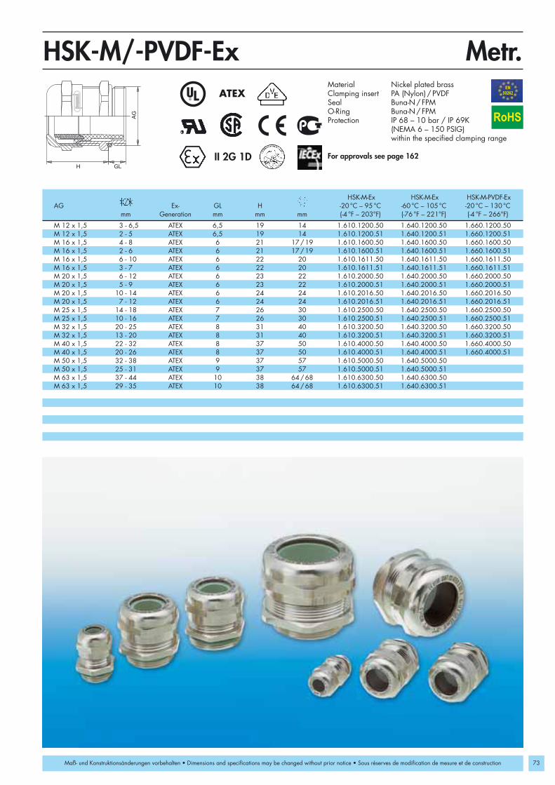
M 12 x 1,5 3 - 6,5 ATEX 6,5 19 14 1.610.1200.50 1.640.1200.50 1.660.1200.50M 12 x 1,5 2 - 5 ATEX 6,5 19 14 1.610.1200.51 1.640.1200.51 1.660.1200.51M 16 x 1,5 4 - 8 ATEX 6 21 17/19 1.610.1600.50 1.640.1600.50 1.660.1600.50M 16 x 1,5 2 - 6 ATEX 6 21 17/19 1.610.1600.51 1.640.1600.51 1.660.1600.51M 16 x 1,5 6 - 10 ATEX 6 22 20 1.610.1611.50 1.640.1611.50 1.660.1611.50M 16 x 1,5 3 - 7 ATEX 6 22 20 1.610.1611.51 1.640.1611.51 1.660.1611.51M 20 x 1,5 6 - 12 ATEX 6 23 22 1.610.2000.50 1.640.2000.50 1.660.2000.50M 20 x 1,5 5 - 9 ATEX 6 23 22 1.610.2000.51 1.640.2000.51 1.660.2000.51 M 20 x 1,5 10 - 14 ATEX 6 24 24 1.610.2016.50 1.640.2016.50 1.660.2016.50M 20 x 1,5 7 - 12 ATEX 6 24 24 1.610.2016.51 1.640.2016.51 1.660.2016.51M 25 x 1,5 14 - 18 ATEX 7 26 30 1.610.2500.50 1.640.2500.50 1.660.2500.50M 25 x 1,5 10 - 16 ATEX 7 26 30 1.610.2500.51 1.640.2500.51 1.660.2500.51M 32 x 1,5 20 - 25 ATEX 8 31 40 1.610.3200.50 1.640.3200.50 1.660.3200.50M 32 x 1,5 13 - 20 ATEX 8 31 40 1.610.3200.51 1.640.3200.51 1.660.3200.51M 40 x 1,5 22 - 32 ATEX 8 37 50 1.610.4000.50 1.640.4000.50 1.660.4000.50M 40 x 1,5 20 - 26 ATEX 8 37 50 1.610.4000.51 1.640.4000.51 1.660.4000.51M 50 x 1,5 32 - 38 ATEX 9 37 57 1.610.5000.50 1.640.5000.50M 50 x 1,5 25 - 31 ATEX 9 37 57 1.610.5000.51 1.640.5000.51M 63 x 1,5 37 - 44 ATEX 10 38 64/68 1.610.6300.50 1.640.6300.50M 63 x 1,5 29 - 35 ATEX 10 38 64/68 1.610.6300.51 1.640.6300.51
AG
H GL
Metr.HSK-M/-PVDF-ExEN50262ATEX
73
II 2G 1D
RoHS
Maß- und Konstruktionsänderungen vorbehalten • Dimensions and specifications may be changed without prior notice • Sous réserves de modification de mesure et de construction
Material Nickel plated brassClamping insert PA (Nylon) / PVDFSeal Buna-N/FPMO-Ring Buna-N/FPMProtection IP 68 – 10 bar / IP 69K
(NEMA 6 – 150 PSIG) within the specified clamping range
For approvals see page 162
HSK-M-Ex HSK-M-Ex HSK-M-PVDF-ExAG Ex- GL H -20 °C – 95 °C -60 °C – 105 °C -20 °C – 130 °C
mm Generation mm mm mm (-4 °F – 203°F) (-76 °F – 221°F) (-4 °F – 266°F)

74
M 12 x 1,5 3 - 6,5 ATEX 15 21 15 1.291.1200.30 1.291.1201.30 1.291.1202.30M 12 x 1,5 2 - 5 ATEX 15 21 15 1.291.1200.31 1.291.1201.31 1.291.1202.31M 16 x 1,5 4 - 8 ATEX 15 22 19 1.291.1600.30 1.291.1601.30 1.291.1602.30M 16 x 1,5 3 - 6 ATEX 15 22 19 1.291.1600.31 1.291.1601.31 1.291.1602.31M 16 x 1,5 5 - 10 ATEX 15 25 22 1.295.1600.30 1.295.1601.30 1.295.1602.30M 16 x 1,5 3 - 7 ATEX 15 25 22 1.295.1600.31 1.295.1601.31 1.295.1602.31M 20 x 1,5 6,5 - 12 ATEX 15 27 24 1.291.2000.30 1.291.2001.30 1.291.2002.30M 20 x 1,5 5 - 9 ATEX 15 27 24 1.291.2000.31 1.291.2001.31 1.291.2002.31M 20 x 1,5 10 - 14 ATEX 15 28 27 1.295.2000.30 1.295.2001.30 1.295.2002.30M 20 x 1,5 7 - 12 ATEX 15 28 27 1.295.2000.31 1.295.2001.31 1.295.2002.31M 25 x 1,5 13 - 18 ATEX 15 31 33 1.291.2500.30 1.291.2501.30 1.291.2502.30M 25 x 1,5 9 - 16 ATEX 15 31 33 1.291.2500.31 1.291.2501.31 1.291.2502.31M 32 x 1,5 18 - 25 ATEX 15 39 42 1.291.3200.30 1.291.3201.30 1.291.3202.30M 32 x 1,5 13 - 20 ATEX 15 39 42 1.291.3200.31 1.291.3201.31 1.291.3202.31M 40 x 1,5 22 - 32 ATEX 18 48 53 1.291.4000.30 1.291.4001.30 1.291.4002.30M 40 x 1,5 20 - 26 ATEX 18 48 53 1.291.4000.31 1.291.4001.31 1.291.4002.31M 50 x 1,5 32 - 38 ATEX 18 49 60 1.291.5000.30 1.291.5001.30 1.291.5002.30M 50 x 1,5 25 - 31 ATEX 18 49 60 1.291.5000.31 1.291.5001.31 1.291.5002.31M 63 x 1,5 37 - 44 ATEX 18 49 65/68 1.291.6300.30 1.291.6301.30 1.291.6302.30M 63 x 1,5 29 - 35 ATEX 18 49 65/68 1.291.6300.31 1.291.6301.31 1.291.6302.31
AG
H
HSK-K-ExEN50262ATEX
II 2G 1D
RoHS
Maß- und Konstruktionsänderungen vorbehalten • Dimensions and specifications may be changed without prior notice • Sous réserves de modification de mesure et de construction
Metr.-elongatedMaterial PA (Nylon) V0 according to UL 94Seal Buna-NO-Ring Buna-NProtection IP 68 – 10 bar / IP 69K
(NEMA 6 – 150 PSIG) within the specified clamping range
OperatingTemperature -20 °C – 95 °C (-4 °F – 203 °F)Colors grey RAL 7035
black RAL 9005blue RAL 5012
For approvals see page 162
AG Ex- GL H Number Number Numbermm Generation mm mm mm grey black blue
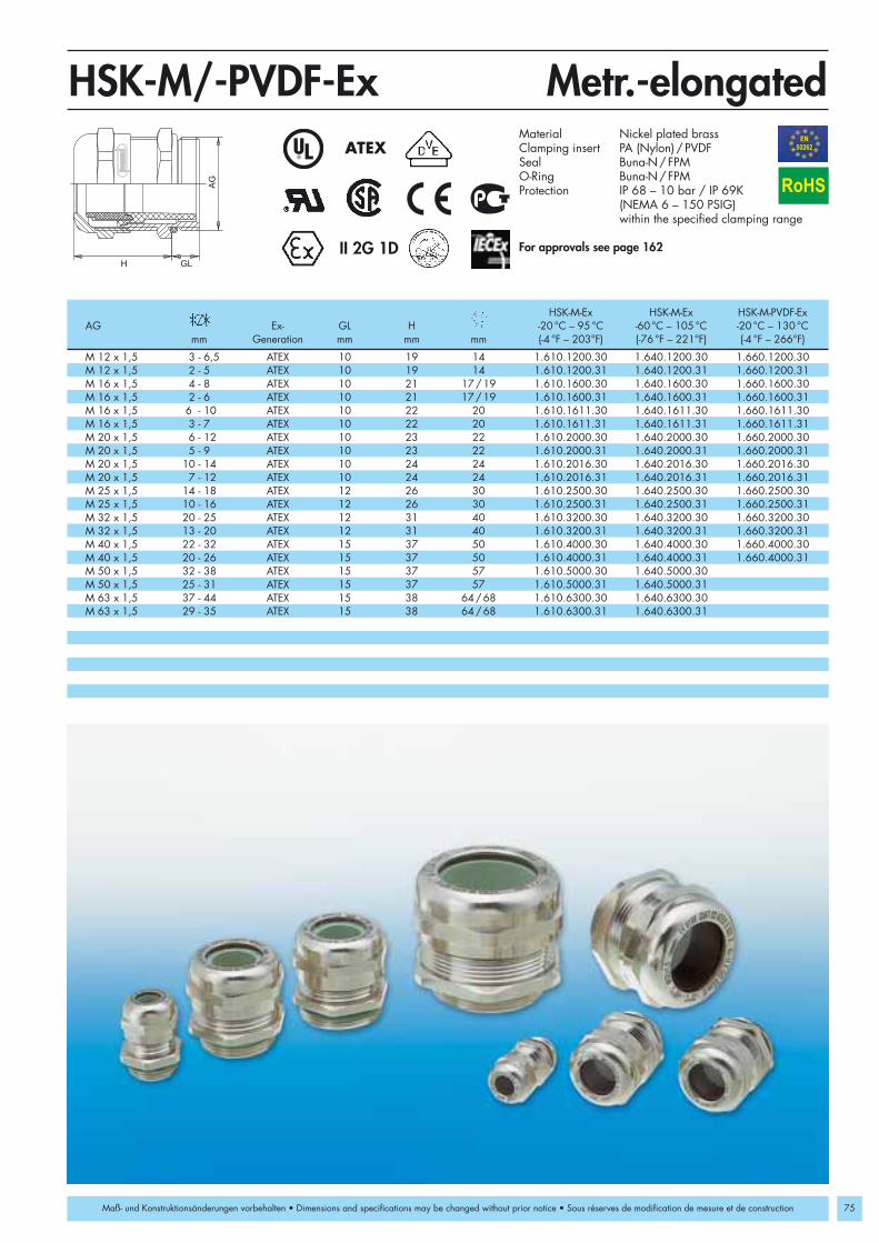
M 12 x 1,5 3 - 6,5 ATEX 10 19 14 1.610.1200.30 1.640.1200.30 1.660.1200.30M 12 x 1,5 2 - 5 ATEX 10 19 14 1.610.1200.31 1.640.1200.31 1.660.1200.31M 16 x 1,5 4 - 8 ATEX 10 21 17/19 1.610.1600.30 1.640.1600.30 1.660.1600.30M 16 x 1,5 2 - 6 ATEX 10 21 17/19 1.610.1600.31 1.640.1600.31 1.660.1600.31M 16 x 1,5 6 - 10 ATEX 10 22 20 1.610.1611.30 1.640.1611.30 1.660.1611.30M 16 x 1,5 3 - 7 ATEX 10 22 20 1.610.1611.31 1.640.1611.31 1.660.1611.31M 20 x 1,5 6 - 12 ATEX 10 23 22 1.610.2000.30 1.640.2000.30 1.660.2000.30M 20 x 1,5 5 - 9 ATEX 10 23 22 1.610.2000.31 1.640.2000.31 1.660.2000.31M 20 x 1,5 10 - 14 ATEX 10 24 24 1.610.2016.30 1.640.2016.30 1.660.2016.30M 20 x 1,5 7 - 12 ATEX 10 24 24 1.610.2016.31 1.640.2016.31 1.660.2016.31M 25 x 1,5 14 - 18 ATEX 12 26 30 1.610.2500.30 1.640.2500.30 1.660.2500.30M 25 x 1,5 10 - 16 ATEX 12 26 30 1.610.2500.31 1.640.2500.31 1.660.2500.31M 32 x 1,5 20 - 25 ATEX 12 31 40 1.610.3200.30 1.640.3200.30 1.660.3200.30M 32 x 1,5 13 - 20 ATEX 12 31 40 1.610.3200.31 1.640.3200.31 1.660.3200.31M 40 x 1,5 22 - 32 ATEX 15 37 50 1.610.4000.30 1.640.4000.30 1.660.4000.30M 40 x 1,5 20 - 26 ATEX 15 37 50 1.610.4000.31 1.640.4000.31 1.660.4000.31M 50 x 1,5 32 - 38 ATEX 15 37 57 1.610.5000.30 1.640.5000.30M 50 x 1,5 25 - 31 ATEX 15 37 57 1.610.5000.31 1.640.5000.31M 63 x 1,5 37 - 44 ATEX 15 38 64/68 1.610.6300.30 1.640.6300.30M 63 x 1,5 29 - 35 ATEX 15 38 64/68 1.610.6300.31 1.640.6300.31
AG
H GL
HSK-M/-PVDF-ExEN50262ATEX
75
RoHS
II 2G 1D
Maß- und Konstruktionsänderungen vorbehalten • Dimensions and specifications may be changed without prior notice • Sous réserves de modification de mesure et de construction
Metr.-elongatedMaterial Nickel plated brassClamping insert PA (Nylon) / PVDFSeal Buna-N/FPMO-Ring Buna-N/FPMProtection IP 68 – 10 bar / IP 69K
(NEMA 6 – 150 PSIG)within the specified clamping range
For approvals see page 162
HSK-M-Ex HSK-M-Ex HSK-M-PVDF-ExAG Ex- GL H -20 °C – 95 °C -60 °C – 105 °C -20 °C – 130 °C
mm Generation mm mm mm (-4 °F – 203°F) (-76 °F – 221°F) (-4 °F – 266°F)

76
PG 7 3 - 6,5 ATEX 8 21 15 1.291.0700.14 1.291.0701.14 1.291.0702.14PG 7 2 - 5 ATEX 8 21 15 1.291.0700.15 1.291.0701.15 1.291.0702.15PG 9 4 - 8 ATEX 8 22 19 1.291.0900.14 1.291.0901.14 1.291.0902.14PG 9 3 - 6 ATEX 8 22 19 1.291.0900.15 1.291.0901.15 1.291.0902.15PG 11 5 - 10 ATEX 8 25 22 1.291.1100.14 1.291.1101.14 1.291.1102.14PG 11 3 - 7 ATEX 8 25 22 1.291.1100.15 1.291.1101.15 1.291.1102.15PG 13,5 6,5 - 12 ATEX 9 27 24 1.291.1300.14 1.291.1301.14 1.291.1302.14PG 13,5 5 - 9 ATEX 9 27 24 1.291.1300.15 1.291.1301.15 1.291.1302.15PG 16 10 - 14 ATEX 10 28 27 1.291.1600.14 1.291.1601.14 1.291.1602.14PG 16 7 - 12 ATEX 10 28 27 1.291.1600.15 1.291.1601.15 1.291.1602.15PG 21 13 - 18 ATEX 11 31 33 1.291.2100.14 1.291.2101.14 1.291.2102.14PG 21 9 - 16 ATEX 11 31 33 1.291.2100.15 1.291.2101.15 1.291.2102.15PG 29 18 - 25 ATEX 11 39 42 1.291.2900.14 1.291.2901.14 1.291.2902.14PG 29 13 - 20 ATEX 11 39 42 1.291.2900.15 1.291.2901.15 1.291.2902.15PG 36 22 - 32 ATEX 13 48 53 1.291.3600.14 1.291.3601.14 1.291.3602.14PG 36 20 - 26 ATEX 13 48 53 1.291.3600.15 1.291.3601.15 1.291.3602.15PG 42 32 - 38 ATEX 13 49 60 1.291.4200.14 1.291.4201.14 1.291.4202.14PG 42 25 - 31 ATEX 13 49 60 1.291.4200.15 1.291.4201.15 1.291.4202.15PG 48 37 - 44 ATEX 14 49 65 1.291.4800.14 1.291.4801.14 1.291.4802.14PG 48 29 - 35 ATEX 14 49 65 1.291.4800.15 1.291.4801.15 1.291.4802.15
AG
H
PGHSK-K-ExATEX
II 2G 1D
RoHS
Maß- und Konstruktionsänderungen vorbehalten • Dimensions and specifications may be changed without prior notice • Sous réserves de modification de mesure et de construction
Material PA (Nylon) V0 acc. to UL 94Seal Buna-NO-Ring Buna-NProtection IP 68 – 10 bar / IP 69K
(NEMA 6 – 150 PSIG) within the specified clamping range
OperationTemperature -20 °C – 95 °C (-4 °F – 203 °F)Colors grey RAL 7035
black RAL 9005blue RAL 5012
For approvals see page 162
AG Ex- GL H Number Number Numbermm Generation mm mm mm grey black blue

PG 7 3 - 6,5 ATEX 5 19 14 1.610.0700.01 1.640.0700.01 1.660.0700.01PG 7 2 - 5 ATEX 5 19 14 1.610.0700.15 1.640.0700.15 1.660.0700.15PG 9 4 - 8 ATEX 6 21 17 1.610.0900.01 1.640.0900.01 1.660.0900.01PG 9 2 - 6 ATEX 6 21 17 1.610.0900.15 1.640.0900.15 1.660.0900.15PG 11 6 - 10 ATEX 6 22 20 1.610.1100.01 1.640.1100.01 1.660.1100.01PG 11 3 - 7 ATEX 6 22 20 1.610.1100.15 1.640.1100.15 1.660.1100.15PG 13,5 6 - 12 ATEX 6,5 24 22 1.610.1300.01 1.640.1300.01 1.660.1300.01PG 13,5 5 - 9 ATEX 6,5 24 22 1.610.1300.15 1.640.1300.15 1.660.1300.15PG 16 10 - 14 ATEX 6,5 23 24 1.610.1600.01 1.640.1600.01 1.660.1600.01PG 16 7 - 12 ATEX 6,5 23 24 1.610.1600.15 1.640.1600.15 1.660.1600.15PG 21 14 - 18 ATEX 7 24 30 1.610.2100.01 1.640.2100.01 1.660.2100.01PG 21 10 - 16 ATEX 7 24 30 1.610.2100.15 1.640.2100.15 1.660.2100.15PG 29 20 - 25 ATEX 8 29 40 1.610.2900.01 1.640.2900.01 1.660.2900.01PG 29 13 - 20 ATEX 8 29 40 1.610.2900.15 1.640.2900.15 1.660.2900.15PG 36 22 - 32 ATEX 8 35 50 1.610.3600.01 1.640.3600.01 1.660.3600.01PG 36 20 - 26 ATEX 8 35 50 1.610.3600.15 1.640.3600.15 1.660.3600.15PG 42 32 - 38 ATEX 9 37 57 1.610.4200.01 1.640.4200.01 1.660.4200.01PG 42 25 - 31 ATEX 9 37 57 1.610.4200.15 1.640.4200.15 1.660.4200.15PG 48 37 - 44 ATEX 10 38 64 1.610.4800.01 1.640.4800.01 1.660.4800.01PG 48 29 - 35 ATEX 10 38 64 1.610.4800.15 1.640.4800.15 1.660.4800.15
AG
H GL
PGHSK-M/-PVDF-ExATEX
77
RoHS
II 2G 1D
Maß- und Konstruktionsänderungen vorbehalten • Dimensions and specifications may be changed without prior notice • Sous réserves de modification de mesure et de construction
Material Nickel plated brassClamping insert PA (Nylon) / PVDFSeal Buna-N/FPMO-Ring Buna-N/FPMProtection IP 68 – 10 bar / IP 69K
(NEMA 6 – 150 PSIG) within the specified clamping range
For approvals see page 162
HSK-M-Ex HSK-M-Ex HSK-M-PVDF-ExAG Ex- GL H -20 °C – 95 °C -60 °C – 105 °C -20 °C – 130 °C
mm Generation mm mm mm (-4 °F – 203°F) (-76 °F – 221°F) (-4 °F – 266°F)

78
PG 7 3 - 6,5 ATEX 15 21 15 1.291.0700.60 1.291.0701.60 1.291.0702.60PG 7 2 - 5 ATEX 15 21 15 1.291.0700.61 1.291.0701.61 1.291.0702.61PG 9 4 - 8 ATEX 15 22 19 1.291.0900.60 1.291.0901.60 1.291.0902.60PG 9 3 - 6 ATEX 15 22 19 1.291.0900.61 1.291.0901.61 1.291.0902.61PG 11 5 - 10 ATEX 15 25 22 1.291.1100.60 1.291.1101.60 1.291.1102.60PG 11 3 - 7 ATEX 15 25 22 1.291.1100.61 1.291.1101.61 1.291.1102.61PG 13,5 6,5 - 12 ATEX 15 27 24 1.291.1300.60 1.291.1301.60 1.291.1302.60PG 13,5 5 - 9 ATEX 15 27 24 1.291.1300.61 1.291.1301.61 1.291.1302.61PG 16 10 - 14 ATEX 15 28 27 1.291.1600.60 1.291.1601.60 1.291.1602.60PG 16 7 - 12 ATEX 15 28 27 1.291.1600.61 1.291.1601.61 1.291.1602.61PG 21 13 - 18 ATEX 15 31 33 1.291.2100.60 1.291.2101.60 1.291.2102.60PG 21 9 - 16 ATEX 15 31 33 1.291.2100.61 1.291.2101.61 1.291.2102.61PG 29 18 - 25 ATEX 15 39 42 1.291.2900.60 1.291.2901.60 1.291.2902.60PG 29 13 - 20 ATEX 15 39 42 1.291.2900.61 1.291.2901.61 1.291.2902.61PG 36 22 - 32 ATEX 18 48 53 1.291.3600.60 1.291.3601.60 1.291.3602.60PG 36 20 - 26 ATEX 18 48 53 1.291.3600.61 1.291.3601.61 1.291.3602.61PG 42 32 - 38 ATEX 18 49 60 1.291.4200.60 1.291.4201.60 1.291.4202.60PG 42 25 - 31 ATEX 18 49 60 1.291.4200.61 1.291.4201.61 1.291.4202.61PG 48 37 - 44 ATEX 18 49 65 1.291.4800.60 1.291.4801.60 1.291.4802.60PG 48 29 - 35 ATEX 18 49 65 1.291.4800.61 1.291.4801.61 1.291.4802.61
AG
H
HSK-K-ExATEX
II 2G 1D
RoHS
Maß- und Konstruktionsänderungen vorbehalten • Dimensions and specifications may be changed without prior notice • Sous réserves de modification de mesure et de construction
PG-elongatedMaterial PA (Nylon) V0 acc. to UL 94Seal Buna-NO-Ring Buna-NProtection IP 68 – 10 bar / IP 69K
(NEMA 6 – 150 PSIG) within the specified clamping range
OperatingTemperature -20 °C – 95 °C (-4 °F – 203 °F)Colors grey RAL 7035
black RAL 9005blue RAL 5012
For approvals see page 162
AG Ex- GL H Number Number Numbermm Generation mm mm mm grey black blue

PG 7 3 - 6,5 ATEX 10 19 14 1.610.0700.60 1.640.0700.60 1.660.0700.60PG 7 2 - 5 ATEX 10 19 14 1.610.0700.61 1.640.0700.61 1.660.0700.61PG 9 4 - 8 ATEX 10 21 17 1.610.0900.60 1.640.0900.60 1.660.0900.60PG 9 2 - 6 ATEX 10 21 17 1.610.0900.61 1.640.0900.61 1.660.0900.61PG 11 6 - 10 ATEX 10 22 20 1.610.1100.60 1.640.1100.60 1.660.1100.60PG 11 3 - 7 ATEX 10 22 20 1.610.1100.61 1.640.1100.61 1.660.1100.61PG 13,5 6 - 12 ATEX 10 24 22 1.610.1300.60 1.640.1300.60 1.660.1300.60PG 13,5 5 - 9 ATEX 10 24 22 1.610.1300.61 1.640.1300.61 1.660.1300.61PG 16 10 - 14 ATEX 10 23 24 1.610.1600.60 1.640.1600.60 1.660.1600.60PG 16 7 - 12 ATEX 10 23 24 1.610.1600.61 1.640.1600.61 1.660.1600.61PG 21 14 - 18 ATEX 12 24 30 1.610.2100.60 1.640.2100.60 1.660.2100.60PG 21 10 - 16 ATEX 12 24 30 1.610.2100.61 1.640.2100.61 1.660.2100.61PG 29 20 - 25 ATEX 12 29 40 1.610.2900.60 1.640.2900.60 1.660.2900.60PG 29 13 - 20 ATEX 12 29 40 1.610.2900.61 1.640.2900.61 1.660.2900.61PG 36 22 - 32 ATEX 15 35 50 1.610.3600.60 1.640.3600.60 1.660.3600.60PG 36 20 - 26 ATEX 15 35 50 1.610.3600.61 1.640.3600.61 1.660.3600.61PG 42 32 - 38 ATEX 15 37 57 1.610.4200.60 1.640.4200.60 1.660.4200.60PG 42 25 - 31 ATEX 15 37 57 1.610.4200.61 1.640.4200.61 1.660.4200.61PG 48 37 - 44 ATEX 15 38 64 1.610.4800.60 1.640.4800.60 1.660.4800.60PG 48 29 - 35 ATEX 15 38 64 1.610.4800.61 1.640.4800.61 1.660.4800.61
AG
H GL
HSK-M/-PVDF-ExATEX
79
RoHS
II 2G 1D
Maß- und Konstruktionsänderungen vorbehalten • Dimensions and specifications may be changed without prior notice • Sous réserves de modification de mesure et de construction
PG-elongatedMaterial Nickel plated brassClamping insert PA (Nylon) / PVDFSeal Buna-N/FPMO-Ring Buna-N/FPMProtection IP 68 – 10 bar / IP 69K
(NEMA 6 – 150 PSIG) within the specified clamping range
For approvals see page 162
HSK-M-Ex HSK-M-Ex HSK-M-PVDF-ExAG Ex- GL H -20 °C – 95 °C -60 °C – 105 °C -20 °C – 130 °C
mm Generation mm mm mm (-4 °F – 203°F) (-76 °F – 221°F) (-4 °F – 266°F)

80
3/8” NPT 4 - 8 ATEX 15 22 22/19 1.291.3800.70 1.291.3801.70 1.291.3802.703/8” NPT 2 - 6 ATEX 15 22 22/19 1.291.3800.71 1.291.3801.71 1.291.3802.711/2” NPT 6,5 - 12 ATEX 13 27 24 1.291.1200.70 1.291.1201.70 1.291.1202.701/2” NPT 5 - 9 ATEX 13 27 24 1.291.1200.71 1.291.1201.71 1.291.1202.711/2” NPT/16 10 - 14 ATEX 13 28 27 1.291.1216.70 1.291.1217.70 1.291.1218.701/2” NPT/16 7 - 12 ATEX 13 28 27 1.291.1216.71 1.291.1217.71 1.291.1218.713/4” NPT 13 - 18 ATEX 14 31 33 1.291.3400.70 1.291.3401.70 1.291.3402.703/4” NPT 9 - 16 ATEX 14 31 33 1.291.3400.71 1.291.3401.71 1.291.3402.711” NPT 18 - 25 ATEX 19 39 42 1.291.1000.70 1.291.1001.70 1.291.1002.701” NPT 13 - 20 ATEX 19 39 42 1.291.1000.71 1.291.1001.71 1.291.1002.711 1/4” NPT 18 - 25 ATEX 16 39 46/42 1.291.5400.70 1.291.5401.70 1.291.5402.701 1/4” NPT 13 - 20 ATEX 16 39 46/42 1.291.5400.71 1.291.5401.71 1.291.5402.711 1/2” NPT 22 - 32 ATEX 20 48 53 1.291.6400.70 1.291.6401.70 1.291.6402.701 1/2” NPT 20 - 26 ATEX 20 48 53 1.291.6400.71 1.291.6401.71 1.291.6402.71
AG
H
NPTHSK-K-ExATEX
II 2G 1D
RoHS
Maß- und Konstruktionsänderungen vorbehalten • Dimensions and specifications may be changed without prior notice • Sous réserves de modification de mesure et de construction
Material PA (Nylon) V0 according to UL 94Seal Buna-NO-Ring Buna-NProtection IP 68 – 10 bar / IP 69K
(NEMA 6 – 150 PSIG) within the specified clamping range
OperatingTemperature -20 °C – 95 °C (-4 °F – 203 °F)Colors grey RAL 7035
black RAL 9005blue RAL 5012
For approvals see page 162
AG Ex- GL H Number Number Numbermm Generation mm mm mm grey black blue

3/8” NPT 4 - 8 ATEX 15 21 17/19 1.610.3800.70 1.640.3800.70 1.660.3800.703/8” NPT 2 - 6 ATEX 15 21 17/19 1.610.3800.71 1.640.3800.71 1.660.3800.711/2” NPT 6 - 12 ATEX 13 24 22/24 1.610.1200.70 1.640.1200.70 1.660.1200.701/2” NPT 5 - 9 ATEX 13 24 22/24 1.610.1200.71 1.640.1200.71 1.660.1200.713/4” NPT 14 - 18 ATEX 13 25 30 1.610.3400.70 1.640.3400.70 1.660.3400.703/4” NPT 10 - 16 ATEX 13 25 30 1.610.3400.71 1.640.3400.71 1.660.3400.711” NPT 20 - 25 ATEX 19 29 40 1.610.1000.70 1.640.1000.701” NPT 13 - 20 ATEX 19 29 40 1.610.1000.71 1.640.1000.71
AG
H GL
NPTHSK-M/-PVDF-ExATEX
81
RoHS
II 2G 1D
Maß- und Konstruktionsänderungen vorbehalten • Dimensions and specifications may be changed without prior notice • Sous réserves de modification de mesure et de construction
Material Nickel platen brassClamping insert PA (Nylon) / PVDFSeal Buna-N/FPMO-Ring Buna-N/FPMProtection IP 68 – 10 bar / IP 69K
(NEMA 6 – 150 PSIG) within the specified clamping range
For approvals see page 162
HSK-M-Ex HSK-M-Ex HSK-M-PVDF-ExAG Ex- GL H -20 °C – 95 °C -60 °C – 105 °C -20 °C – 130 °C
mm Generation mm mm mm (-4 °F – 203°F) (-76 °F – 221°F) (-4 °F – 266°F)

82
M 16 x 1,5 8 22 19 4 x 1,4 1.599.1600.50 1.599.1600.51 2 x 3 1.599.1601.50 1.599.1601.51M 20 x 1,5 9 27 24 6 x 3 1.599.2001.50 1.599.2001.51 2 x 5 1.599.2003.50 1.599.2003.51M 25 x 1,5 11 31 33 4 x 6 1.599.2500.50 1.599.2500.51 3 x 7 1.599.2501.50 1.599.2501.51M 32 x 1,5 11 39 42 6 x 6,5 1.599.3200.50 1.599.3200.51 4 x 9 1.599.3201.50 1.599.3201.51M 40 x 1,5 13 48 53 7 x 9 1.599.4001.50 1.599.4001.51 2 x 15 1.599.4003.50 1.599.4003.51M 50 x 1,5 13 49 60 1.599.5099.50 1.599.5099.51M 63 x 1,5 14 49 65/68 6 x 12 1.599.6301.50 1.599.6301.51 3 x 18 1.599.6302.50 1.599.6302.51
PG 9 8 22 19 4 x 1,4 1.599.0900.00 1.599.0900.01 2 x 3 1.599.0901.00 1.599.0901.01PG 11 8 25 22 2 x 4 1.599.1102.00 1.599.1102.01 3 x 3 1.599.1101.00 1.599.1101.01PG 13,5 9 27 24 3 x 4 1.599.1302.00 1.599.1302.01 2 x 5 1.599.1303.00 1.599.1303.01PG 16 10 28 27 4 x 4 1.599.1602.00 1.599.1602.01 6 x 4 1.599.1604.00 1.599.1604.01PG 16 10 28 27 3 x 5,6 1.599.1606.00 1.599.1606.01 2 x 6 1.599.1605.00 1.599.1605.01PG 21 11 31 33 4 x 6 1.599.2100.00 1.599.2100.01 3 x 7 1.599.2101.00 1.599.2101.01PG 29 11 39 42 6 x 6,5 1.599.2900.00 1.599.2900.01 4 x 9 1.599.2901.00 1.599.2901.01PG 36 13 48 53 7 x 9 1.599.3601.00 1.599.3601.01 2 x 15 1.599.3603.00 1.599.3603.01PG 48 14 49 65 6 x 12 1.599.4801.00 1.599.4801.01 3 x 18 1.599.4802.00 1.599.4802.01
3/8" NPT 15 22 19/22 4 x 1,4 1.599.3800.70 1.599.3800.71 2 x 3 1.599.3801.70 1.599.3801.711/2" NPT 13 27 24 3 x 4 1.599.1202.70 1.599.1202.71 2 x 5 1.599.1203.70 1.599.1203.711/2" NPT/16 13 28 27 6 x 4 1.599.1220.70 1.599.1220.71 2 x 6 1.599.1221.70 1.599.1221.713/4" NPT 14 31 33 4 x 6 1.599.3400.70 1.599.3400.71 3 x 7 1.599.3401.70 1.599.3401.711" NPT 19 39 42 6 x 6,5 1.599.1000.70 1.599.1000.71 4 x 9 1.599.1001.70 1.599.1001.711 1/4" NPT 16 39 42/46 1.599.5499.70 1.599.5499.711 1/2" NPT 20 48 53 5 x 9 1.599.6400.70 1.599.6400.71 7 x 9 1.599.6401.70 1.599.6401.71
AG
H GL
Metr./PG/NPTHSK-K-Multi-ExMATEX
II 2G 1D
RoHS
Maß- und Konstruktionsänderungen vorbehalten • Dimensions and specifications may be changed without prior notice • Sous réserves de modification de mesure et de construction
Number NumberAG GL H of Holes Number Number of Holes Number Number
mm mm mm x d grey black x d grey black
Material PA (Nylon) V0 according to UL 94Seal ElastomerProtection IP 65 (NEMA 4x)
IP 68 possible with ideal fitOperatingTemperature -20 °C – 95 °C (-4 °F – 203 °F)Colors grey RAL 7035
black RAL 9005
These inserts are examples, other inserts available upon requestCertifications and installation instructions see page 162

AG
GLH
Metr./PG/NPTHSK-M-Multi-ExM
83
ATEX
M 16 x 1,5 6 21 17/19 4 x 1,4 1.687.1600.50 2 x 3 1.687.1601.50M 20 x 1,5 6 23 22 6 x 3 1.687.2001.50 2 x 5 1.687.2003.50M 25 x 1,5 7 26 30 4 x 6 1.687.2500.50 3 x 7 1.687.2501.50M 32 x 1,5 8 31 40 6 x 6,5 1.687.3200.50 4 x 9 1.687.3201.50M 40 x 1,5 8 37 50 7 x 9 1.687.4001.50 2 x 15 1.687.4003.50M 50 x 1,5 9 37 57 1.687.5099.50M 63 x 1,5 10 38 64/68 6 x 12 1.687.6301.50 3 x 18 1.687.6302.50
PG 9 6 21 17 4 x 1,4 1.687.0900.01 2 x 3 1.687.0901.01PG 11 6 22 20 2 x 4 1.687.1102.01 3 x 3 1.687.1101.01PG 13,5 6,5 24 22 3 x 4 1.687.1302.01 2 x 5 1.687.1303.01PG 16 6,5 23 24 4 x 4 1.687.1602.01 6 x 4 1.687.1604.01PG 16 6,5 23 24 3 x 5,6 1.687.1606.01 2 x 6 1.687.1605.01PG 21 7 24 30 4 x 6 1.687.2100.01 3 x 7 1.687.2101.01PG 29 8 29 40 6 x 6,5 1.687.2900.01 4 x 9 1.687.2901.01PG 36 8 35 50 7 x 9 1.687.3601.01 2 x 15 1.687.3603.01PG 48 10 38 64 6 x 12 1.687.4801.01 3 x 18 1.687.4802.01
3/8" NPT 15 21 17/19 4 x 1,4 1.687.3800.70 2 x 3 1.687.3801.701/2" NPT/16 13 24 22/24 3 x 4 1.687.1220.70 2 x 5 1.687.1221.703/4" NPT 13 25 30 4 x 6 1.687.3400.70 3 x 7 1.687.3401.701" NPT 19 29 40 6 x 6,5 1.687.1000.70 4 x 9 1.687.1001.70
II 2G 1D
RoHS
Maß- und Konstruktionsänderungen vorbehalten • Dimensions and specifications may be changed without prior notice • Sous réserves de modification de mesure et de construction
Material Nickel plated brassClamping insert PA (Nylon)Seal ElastomerO-Ring Buna-NProtection IP 65
IP 68 possible with ideal fitOperatingTemperature -20 °C – 95 °C (-4 °F – 203 °F)
These inserts are examples, other inserts available upon requestCertifications and installation instructions see page 162
Number NumberAG GL H of Holes Number of Holes Number
mm mm mm x d x d

84
M 20 x 1,5 9 28 27 12 x 7 1.589.2017.50 1.589.2017.51 14 x 6 1.589.2018.50 1.589.2018.51M 25 x 1,5 11 31 33 14 x 6 1.589.2500.50 1.589.2500.51 14 x 7 1.589.2501.50 1.589.2501.51M 32 x 1,5 11 39 42 22 x 8 1.589.3200.50 1.589.3200.51M 40 x 1,5 13 48 53 28,5 x 10 1.589.4000.50 1.589.4000.51 29 x 5,5 1.589.4001.50 1.589.4001.51M 40 x 1,5 13 48 53 30,5 x 12 1.589.4002.50 1.589.4002.51 31 x 7,5 1.589.4003.50 1.589.4003.51M 50 x 1,5 13 49 60 33,5 x 11,5 1.589.5000.50 1.589.5000.51
PG 16 10 28 27 12 x 7 1.589.1601.00 1.589.1601.01 14 x 6 1.589.1602.00 1.589.1602.01PG 21 11 31 33 14 x 6 1.589.2100.00 1.589.2100.01 14 x 7 1.589.2101.00 1.589.2101.01PG 29 11 39 42 22 x 8 1.589.2900.00 1.589.2900.01PG 36 13 48 53 28,5 x 10 1.589.3600.00 1.589.3600.01 29 x 5,5 1.589.3601.00 1.589.3601.01PG 36 13 48 53 30,5 x 12 1.589.3602.00 1.589.3602.01 31 x 7,5 1.589.3603.00 1.589.3603.01PG 42 13 49 60 33,5 x 11,5 1.589.4200.00 1.589.4200.01
1/2” NPT/16 13 28 27 12 x 7 1.589.1217.70 1.589.1217.71 14 x 6 1.589.1218.70 1.589.1218.713/4” NPT 14 31 33 14 x 6 1.589.3400.70 1.589.3400.711” NPT 19 39 42 22 x 8 1.589.1000.70 1.589.1000.711 1/4” NPT 16 39 42/46 22 x 8 1.589.5400.70 1.589.5400.711 1/2” NPT 20 48 53 28,5 x 10 1.589.6400.70 1.589.6400.71 29 x 5,5 1.589.6401.70 1.589.6401.711 1/2” NPT 20 48 53 30,5 x 12 1.589.6402.70 1.589.6402.71 31 x 7,5 1.589.6403.70 1.589.6403.71
AG
H GL
Metr./PG/NPTHSK-K-FLAKA-ExM
RoHS
ATEX
II 2G 1D
Maß- und Konstruktionsänderungen vorbehalten • Dimensions and specifications may be changed without prior notice • Sous réserves de modification de mesure et de construction
Material PA (Nylon) V0 according to UL 94Seal ElastomerOperatingTemperature -20 °C – 95 °C (-4 °F – 203 °F)Colors grey RAL 7035
black RAL 9005
These inserts are examples, other inserts available upon requestCertifications and installation instructions see page 162
AG GL H b x h Number Number b x h Number Numbermm mm mm mm grey black mm grey black

M 20 x 1,5 6 24 24 12 x 7 1.689.2017.50 14 x 6 1.689.2018.50M 25 x 1,5 7 26 30 14 x 6 1.689.2500.50 14 x 7 1.689.2501.50M 32 x 1,5 8 31 40 22 x 8 1.689.3200.50M 40 x 1,5 8 37 50 28,5 x 10 1.689.4000.50 29 x 5,5 1.689.4001.50M 40 x 1,5 8 37 50 30,5 x 12 1.689.4002.50 31 x 7,5 1.689.4003.50M 50 x 1,5 9 37 57 33,5 x 11,5 1.689.5000.50M 63 x 1,5 10 38 64/68 38 x 12 1.689.6300.50
PG 16 6,5 23 24 12 x 7 1.689.1601.01 14 x 6 1.689.1602.01PG 21 7 24 30 14 x 6 1.689.2100.01 14 x 7 1.689.2101.01PG 29 8 29 40 22 x 8 1.689.2900.01PG 36 8 35 50 28,5 x 10 1.689.3600.01 29 x 5,5 1.689.3601.01PG 36 8 35 50 30,5 x 12 1.689.3602.01 31 x 7,5 1.689.3603.01PG 42 9 37 57 33,5 x 11,5 1.689.4200.01PG 48 10 38 64 38 x 12 1.689.4802.01
3/4” NPT 13 25 30 14 x 6 1.689.3400.70 14 x 7 1.689.3401.701” NPT 19 29 40 22 x 8 1.689.1000.70
AG
GLH
Metr./PG/NPTHSK-M-FLAKA-ExM
85
RoHS
ATEX
II 2G 1D
Maß- und Konstruktionsänderungen vorbehalten • Dimensions and specifications may be changed without prior notice • Sous réserves de modification de mesure et de construction
Material Nickel plated brassClamping insert PA (Nylon)Seal ElastomerO-Ring Buna-NOperatingTemperature -20 °C – 95 °C (-4 °F – 203 °F)
These inserts are examples, other inserts available upon requestCertifications and installation instructions see page 162
AG GL H b x h Number b x h Numbermm mm mm mm mm

86
M 12 x 1,5 3 - 6,5 6,5 19 14 1.612.1200.50 1.642.1200.50 1.662.1200.50M 12 x 1,5 2 - 5 6,5 19 14 1.612.1200.51 1.642.1200.51 1.662.1200.51M 16 x 1,5 5 - 10 6 22 22 1.612.1600.50 1.642.1600.50 1.662.1600.50M 16 x 1,5 3 - 7 6 22 22 1.612.1600.51 1.642.1600.51 1.662.1600.51M 20 x 1,5 10 - 14 6 23 24 1.612.2000.50 1.642.2000.50 1.662.2000.50M 20 x 1,5 7 - 12 6 23 24 1.612.2000.51 1.642.2000.51 1.662.2000.51M 25 x 1,5 13 - 18 7 24 30 1.612.2500.50 1.642.2500.50 1.662.2500.50M 25 x 1,5 9 - 16 7 24 30 1.612.2500.51 1.642.2500.51 1.662.2500.51M 32 x 1,5 20 - 25 8 29 41 1.612.3200.50 1.642.3200.50 1.662.3200.50M 32 x 1,5 13 - 20 8 29 41 1.612.3200.51 1.642.3200.51 1.662.3200.51M 40 x 1,5 22 - 32 8 35 50 1.612.4000.50 1.642.4000.50 1.662.4000.50M 40 x 1,5 20 - 26 8 35 50 1.612.4000.51 1.642.4000.51 1.662.4000.51
H GL
AG
Metr.HSK-INOX-/PVDF-ExEN50262
RoHS
ATEX
II 2G 1D
Maß- und Konstruktionsänderungen vorbehalten • Dimensions and specifications may be changed without prior notice • Sous réserves de modification de mesure et de construction
Material 1.4305 (303 SS)Clamping insert PA (Nylon) / PVDFSeal Buna-N/FPMO-Ring Buna-N/FPMProtection IP 68 – 10 bar / IP 69K
within the specified clamping range
For approvals see page 162* EMI version available316 Stainless Steel available upon request
HSK-INOX-Ex* HSK-INOX-Ex* HSK-INOX-PVDF-ExAG GL H -20 °C – 95 °C -60 °C – 105 °C -20 °C – 130 °C
mm mm mm mm (-4 °F – 203°F) (-76 °F – 221°F) (-4 °F – 266°F)

PG 7 3 - 6,5 5 19 14 1.612.0700.01 1.642.0700.01 1.662.0700.01PG 7 2 - 5 5 19 14 1.612.0700.15 1.642.0700.15 1.662.0700.15PG 9 4 - 8 6 21 17 1.612.0900.01 1.642.0900.01 1.662.0900.01PG 9 2 - 6 6 21 17 1.612.0900.15 1.642.0900.15 1.662.0900.15PG 11 5 - 10 6 22 22 1.612.1100.01 1.642.1100.01 1.662.1100.01PG 11 3 - 7 6 22 22 1.612.1100.15 1.642.1100.15 1.662.1100.15PG 13,5 6 - 12 6 24 22 1.612.1300.01 1.642.1300.01 1.662.1300.01PG 13,5 5 - 9 6 24 22 1.612.1300.15 1.642.1300.15 1.662.1300.15PG 16 10 - 14 6 23 24 1.612.1600.01 1.642.1600.01 1.662.1600.01PG 16 7 - 12 6 23 24 1.612.1600.15 1.642.1600.15 1.662.1600.15PG 21 13 - 18 7 24 30 1.612.2100.01 1.642.2100.01 1.662.2100.01PG 21 9 - 16 7 24 30 1.612.2100.15 1.642.2100.15 1.662.2100.15PG 29 20 - 25 8 29 41 1.612.2900.01 1.642.2900.01 1.662.2900.01PG 29 13 - 20 8 29 41 1.612.2900.15 1.642.2900.15 1.662.2900.15PG 36 22 - 32 8 35 50 1.612.3600.01 1.642.3600.01 1.662.3600.01PG 36 20 - 26 8 35 50 1.612.3600.15 1.642.3600.15 1.662.3600.15
H GL
AG
PGHSK-INOX-/PVDF-ExATEX
87
RoHS
II 2G 1D
Maß- und Konstruktionsänderungen vorbehalten • Dimensions and specifications may be changed without prior notice • Sous réserves de modification de mesure et de construction
Material 1.4305 (303 SS)Clamping insert PA (Nylon) / PVDFSeal Buna-N/FPMO-Ring Buna-N/FPMProtection IP 68 – 10 bar / IP 69K
within the specified clamping range
For approvals see page 162EMI version available
316 Stainless Steel available upon request
HSK-INOX-Ex HSK-INOX-Ex HSK-INOX-PVDF-ExAG GL H -20 °C – 95 °C -60 °C – 105 °C -20 °C – 130 °C
mm mm mm mm (-4 °F – 203°F) (-76 °F – 221°F) (-4 °F – 266°F)

88
M 16 x 1,5 4 - 8 ATEX 15 29 19 1.215.1601.50M 20 x 1,5 6 - 12 ATEX 15 35,5 24 1.215.2001.50M 25 x 1,5 13 - 18 ATEX 11 41 33 1.215.2501.50M 32 x 1,5 18 - 25 ATEX 11 49 42 1.215.3201.50M 40 x 1,5 22 - 32 ATEX 13 58 53 1.215.4001.50M 50 x 1,5 32 - 38 ATEX 13 61,5 60 1.215.5001.50M 63 x 1,5 37 - 44 ATEX 14 62 65/68 1.215.6301.50
PG 9 4 - 8 ATEX 15 29 19 1.215.0901.14PG 11 6 - 10 ATEX 15 32,5 22 1.215.1101.14PG 13,5 6 - 12 ATEX 15 35,5 24 1.215.1301.14PG 16 10 - 14 ATEX 10 37,5 27 1.215.1601.14PG 21 13 - 18 ATEX 11 41 33 1.215.2101.14PG 29 18 - 25 ATEX 11 49 42 1.215.2901.14PG 36 22 - 32 ATEX 13 58 53 1.215.3601.14PG 42 32 - 38 ATEX 13 61,5 60 1.215.4201.14PG 48 37 - 44 ATEX 14 62 65 1.215.4801.14
H GL
AG
Metr./PGHSK-K-MZ-ExEN50262
ATEX
RoHS
II 2G 1D
Maß- und Konstruktionsänderungen vorbehalten • Dimensions and specifications may be changed without prior notice • Sous réserves de modification de mesure et de construction
Material PA-ALSeal Buna-NProtection IP 68 – 10 bar / IP 69K
(NEMA 6 – 150 PSIG) within the specified clamping range
OperatingTemperature -20 °C – 70 °C (-4 °F – 158 °F)
For approvals see page 162
AG Ex- GL H Numbermm Generation mm mm mm

M 12 x 1,5 3 - 6,5 ATEX 6,5 26 14 1.611.1200.50 * 1.641.1200.50 * 1.661.1200.50M 16 x 1,5 4 - 8 ATEX 6 28 19 1.611.1600.50 * 1.641.1600.50 * 1.661.1600.50M 16 x 1,5 6 - 10 ATEX 6 30 20 1.611.1611.50 * 1.641.1611.50 * 1.661.1611.50M 20 x 1,5 6 - 12 ATEX 6 33 22 1.611.2000.50 * 1.641.2000.50 * 1.661.2000.50M 20 x 1,5 10 - 14 ATEX 6 33 24 1.611.2016.50 * 1.641.2016.50 * 1.661.2016.50M 25 x 1,5 14 - 18 ATEX 7 37 30 1.611.2500.50 * 1.641.2500.50 * 1.661.2500.50M 32 x 1,5 20 - 25 ATEX 8 43 40 1.611.3200.50 * 1.641.3200.50 * 1.661.3200.50M 40 x 1,5 24 - 32 ATEX 8 50 50 1.611.4000.50 * 1.641.4000.50 * 1.661.4000.50M 50 x 1,5 32 - 38 ATEX 9 51 57 1.611.5000.50 * 1.641.5000.50 *M 63 x 1,5 37 - 44 ATEX 10 52 64/68 1.611.6300.50 * 1.641.6300.50 *
AG
H GL
Metr.HSK-MZ-/PVDF-ExEN50262ATEX
89
RoHS
II 2G 1D
Maß- und Konstruktionsänderungen vorbehalten • Dimensions and specifications may be changed without prior notice • Sous réserves de modification de mesure et de construction
Material Nickel plated brass Clamping insert PA (Nylon) / PVDFSeal Buna-N/FPMO-Ring Buna-N/FPMProtection IP 68 – 10 bar / IP 69K
(NEMA 6 – 150 PSIG) within the specified clamping range
For approvals see page 162Elongated thread for metric and PG sizes available* EMI version available
HSK-MZ-Ex HSK-MZ-Ex HSK-MZ-PVDF-ExAG Ex- GL H -20 °C – 95 °C -60 °C – 105 °C -20 °C – 130 °C
mm Generation mm mm mm (-4 °F – 203°F) (-76 °F – 221°F) (-4 °F – 266°F)

9090
PG 7 3 - 6,5 ATEX 5 26 14 1.611.0700.01 1.641.0700.01 1.661.0700.01PG 9 4 - 8 ATEX 6 28 17 1.611.0900.01 1.641.0900.01 1.661.0900.01PG 11 6 - 10 ATEX 6 30 20 1.611.1100.01 1.641.1100.01 1.661.1100.01PG 13,5 7 - 12 ATEX 6 33 22 1.611.1300.01 1.641.1300.01 1.661.1300.01PG 16 10 - 14 ATEX 6 33 24 1.611.1600.01 1.641.1600.01 1.661.1600.01PG 21 13 - 18 ATEX 7 37 30 1.611.2100.01 1.641.2100.01 1.661.2100.01PG 29 20 - 25 ATEX 8 43 40 1.611.2900.01 1.641.2900.01 1.661.2900.01PG 36 24 - 32 ATEX 8 50 50 1.611.3600.01 1.641.3600.01 1.661.3600.01PG 42 32 - 38 ATEX 9 51 57 1.611.4200.01 1.641.4200.01 1.661.4200.01PG 48 37 - 44 ATEX 10 52 64 1.611.4800.01 1.641.4800.01 1.661.4800.01
3/8” NPT 4 - 8 ATEX 15 28 17/19 1.611.3800.70 1.641.3800.70 1.661.3800.701/2” NPT 7 - 12 ATEX 13 33 22/24 1.611.1200.70 1.641.1200.70 1.661.1200.703/4” NPT 13 - 18 ATEX 13 37 30 1.611.3400.70 1.641.3400.70 1.661.3400.701” NPT 20 - 25 ATEX 19 43 40 1.611.1000.70 1.641.1000.70
AG
H GL
PG/NPTHSK-MZ-/PVDF-ExATEX RoHS
II 2G 1D
Material Nickel plated brass Clamping insert PA (Nylon) / PVDFSeal Buna-N/FPMO-Ring Buna-N/FPMProtection IP 68 – 10 bar / IP 69K
(NEMA 6 – 150 PSIG) within the specified clamping range
For approvals see page 162Elongated thread for metric and PG sizes available* EMI version available
HSK-MZ-Ex HSK-MZ-Ex HSK-MZ-PVDF-ExAG Ex- GL H -20 °C – 95 °C -60 °C – 105 °C -20 °C – 130 °C
mm Generation mm mm mm (-4 °F – 203°F) (-76 °F – 221°F) (-4 °F – 266°F)
Maß- und Konstruktionsänderungen vorbehalten • Dimensions and specifications may be changed without prior notice • Sous réserves de modification de mesure et de construction

Maß- und Konstruktionsänderungen vorbehalten • Dimensions and constructions are subject to alterations without notice • Sous réserves de modification de mesure et de construction 9191ATEX
Strain relief fittings in all popular thread types and sizes forstandard applications in hazardous location type „e“ or „d“according to EN 50014, EN 50018 and EN 50019:
• Machine, apparatus and plant equipment• Measuring control and feedback systems• Control cabinets• Marine• Off-shore
and in all applications where excellent performance, fire resist-ance, and resistance against turning of the cable are critical.
HSK-M-Ex-d Liquid tight strain relief fittings for flame proofenclosures „d” made of nickel plated brass
HSK-MZ-Ex-d Liquid tight strain relief fittings for flame proofenclosures „d” with additional cable clampmade of nickel plated brass
HSK-INOX-Ex-d Liquid tight strain relief fittings for flame proofenclosures „d” made of stainless steel
RSD-Ms-Ex-d Reducing bushing made of nickel plated brass for hazardous locations „d“
RSD-INOX-Ex-d Reducing bushing made of stainless steelfor hazardous locations „d“
V-Ms-Ex-d Threaded brass plug for hazardous locations „d“
V-INOX-Ex-d Threaded stainless steel plugs for hazordouslocations „d“
Setting Standards
HSK-Industry-Ex-d Standard

92
M 12 x 1,5 3 - 6,5 ATEX 14 19 14 1.622.1200.50 1.634.1200.50M 12 x 1,5 2 - 5 ATEX 14 19 14 1.622.1200.51 1.634.1200.51M 16 x 1,5 5 - 10 ATEX 14 22 20 1.622.1600.50 1.634.1600.50M 16 x 1,5 3 - 7 ATEX 14 22 20 1.622.1600.51 1.634.1600.51M 20 x 1,5 10 - 14 ATEX 14 25 24 1.622.2000.50 1.634.2000.50M 20 x 1,5 7 - 12 ATEX 14 25 24 1.622.2000.51 1.634.2000.51M 25 x 1,5 13 - 18 ATEX 14 26,5 30 1.622.2500.50 1.634.2500.50M 25 x 1,5 9 - 16 ATEX 14 26,5 30 1.622.2500.51 1.634.2500.51M 32 x 1,5 18 - 25 ATEX 14 32 40 1.622.3200.50 1.634.3200.50M 32 x 1,5 14 - 20 ATEX 14 32 40 1.622.3200.51 1.634.3200.51M 40 x 1,5 22 - 32 ATEX 14 38,5 50 1.622.4000.50 1.634.4000.50M 40 x 1,5 20 - 26 ATEX 14 38,5 50 1.622.4000.51 1.634.4000.51
M 12 x 1,5 3 - 6,5 ATEX 14 26 14 1.628.1200.50M 16 x 1,5 5 - 10 ATEX 14 30 20 1.628.1600.50M 20 x 1,5 10 - 14 ATEX 14 34 24 1.628.2000.50M 25 x 1,5 13 - 18 ATEX 14 38 30 1.628.2500.50M 32 x 1,5 18 - 25 ATEX 14 44 40 1.628.3200.50M 40 x 1,5 22 - 32 ATEX 14 51,5 50 1.628.4000.50
Metr.HSK-M/MZ-Ex-dM
II 2G 1D Ex d IICATEX
RoHS
HSK-M-Ex-d
HSK-MZ-Ex-d (with additional strain relief)
Maß- und Konstruktionsänderungen vorbehalten • Dimensions and specifications may be changed without prior notice • Sous réserves de modification de mesure et de construction
HSK-M / MZ-Ex-d HSK-M-PVDF-Ex-dAG Ex- GL H -60 °C – 105 °C -20 °C – 130 °C
mm Generation mm mm mm (-76 °F – 221 °F) (-4 °F – 266 °F)
Material Nickel plated brassClamping insert PA (Nylon) / PVDFSeal FPM/FPMO-Ring FPM /FPMProtection IP 68 – 10 bar / IP 69K
(NEMA 6 – 150 PSIG) within the specified clamping range
For approvals see page 162
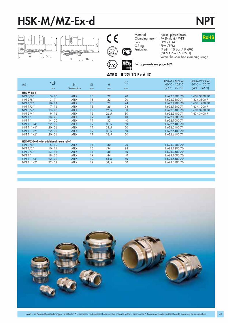
HSK-M/MZ-Ex-d
93
II 2G 1D Ex d IICATEX
NPT 3/8“ 5 - 10 ATEX 15 22 20 1.622.3800.70 1.634.3800.70NPT 3/8“ 3 - 7 ATEX 15 22 20 1.622.3800.71 1.634.3800.71NPT 1/2“ 10 - 14 ATEX 15 25 24 1.622.1200.70 1.634.1200.70NPT 1/2“ 7 - 12 ATEX 15 25 24 1.622.1200.71 1.634.1200.71NPT 3/4“ 13 - 18 ATEX 15 26,5 30 1.622.3400.70 1.634.3400.70NPT 3/4“ 9 - 16 ATEX 15 26,5 30 1.622.3400.71 1.634.3400.71NPT 1“ 18 - 25 ATEX 19 32 40 1.622.1000.70NPT 1“ 14 - 20 ATEX 19 32 40 1.622.1000.71NPT 1 1/4“ 22 - 32 ATEX 19 38,5 50 1.622.5400.70NPT 1 1/4“ 20 - 26 ATEX 19 38,5 50 1.622.5400.71NPT 1 1/2“ 22 - 32 ATEX 19 38,5 50 1.622.6400.70NPT 1 1/2“ 20 - 26 ATEX 19 38,5 50 1.622.6400.71
NPT 3/8“ 5 - 10 ATEX 15 30 20 1.628.3800.70NPT 1/2“ 10 - 14 ATEX 15 34 24 1.628.1200.70NPT 3/4“ 13 - 18 ATEX 15 38 30 1.628.3400.70NPT 1“ 18 - 25 ATEX 19 44 40 1.628.1000.70NPT 1 1/4“ 22 - 32 ATEX 19 51,5 50 1.628.5400.70NPT 1 1/2“ 22 - 32 ATEX 19 51,5 50 1.628.6400.70
NPTRoHS
Maß- und Konstruktionsänderungen vorbehalten • Dimensions and specifications may be changed without prior notice • Sous réserves de modification de mesure et de construction
HSK-M-Ex-d
HSK-MZ-Ex-d (with additional strain relief)
HSK-M / MZ-Ex-d HSK-M-PVDF-Ex-dAG Ex- GL H -60 °C – 105 °C -20 °C – 130 °C
mm Generation mm mm mm (-76 °F – 221 °F) (-4 °F – 266 °F)
Material Nickel plated brassClamping insert PA (Nylon) / PVDFSeal FPM/FPMO-Ring FPM /FPMProtection IP 68 – 10 bar / IP 69K
(NEMA 6 – 150 PSIG) within the specified clamping range
For approvals see page 162

94
HSK-INOX-Ex-d
M 12 x 1,5 3 - 6,5 ATEX 14 19 14 1.632.1200.50 1.633.1200.50M 12 x 1,5 2 - 5 ATEX 14 19 14 1.632.1200.51 1.633.1200.51M 16 x 1,5 5 - 10 ATEX 14 22 20 1.632.1600.50 1.633.1600.50M 16 x 1,5 3 - 7 ATEX 14 22 20 1.632.1600.51 1.633.1600.51M 20 x 1,5 10 - 14 ATEX 14 25 24 1.632.2000.50 1.633.2000.50M 20 x 1,5 7 - 12 ATEX 14 25 24 1.632.2000.51 1.633.2000.51M 25 x 1,5 13 - 18 ATEX 14 26,5 30 1.632.2500.50 1.633.2500.50M 25 x 1,5 9 - 16 ATEX 14 26,5 30 1.632.2500.51 1.633.2500.51M 32 x 1,5 18 - 25 ATEX 14 32 40 1.632.3200.50 1.633.3200.50M 32 x 1,5 14 - 20 ATEX 14 32 40 1.632.3200.51 1.633.3200.51M 40 x 1,5 22 - 32 ATEX 14 38,5 50 1.632.4000.50 1.633.4000.50M 40 x 1,5 20 - 26 ATEX 14 38,5 50 1.632.4000.51 1.633.4000.51
Metr.
II 2G 1D Ex d IICATEX
M
RoHS
HSK-INOX-Ex-d HSK-INOX-PVDF-Ex-dAG Ex- GL H -60 °C – 105 °C -20 °C – 130 °C
mm Generation mm mm mm (-76 °F – 221 °F) (-4 °F – 266 °F)
Material Stainless steel (1.4404)Clamping insert PVDFSeal FPMO-Ring FPMProtection IP 68 – 10 bar / IP 69K
(NEMA 6 – 150 PSIG) within the specified clamping range
For approvals see page 162
Maß- und Konstruktionsänderungen vorbehalten • Dimensions and specifications may be changed without prior notice • Sous réserves de modification de mesure et de construction

95
HSK-INOX-Ex-d
NPT 3/8“ 5 - 10 ATEX 15 22 20 1.632.3800.70 1.633.3800.70NPT 3/8“ 3 - 7 ATEX 15 22 20 1.632.3800.71 1.633.3800.71NPT 1/2“ 10 - 14 ATEX 15 25 24 1.632.1200.70 1.633.1200.70NPT 1/2“ 7 - 12 ATEX 15 25 24 1.632.1200.71 1.633.1200.71NPT 3/4“ 13 - 18 ATEX 15 26,5 30 1.632.3400.70 1.633.3400.70NPT 3/4“ 9 - 16 ATEX 15 26,5 30 1.632.3400.71 1.633.3400.71
NPT
II 2G 1D Ex d IICATEX
RoHS
HSK-INOX-Ex-d HSK-INOX-PVDF-Ex-dAG Ex- GL H -60 °C – 105 °C -20 °C – 130 °C
mm Generation mm mm mm (-76 °F – 221 °F) (-4 °F – 266 °F)
Material Stainless steel (1.4404)Clamping insert PVDFSeal FPMO-Ring FPMProtection IP 68 – 10 bar / IP 69K
(NEMA 6 – 150 PSIG) within the specified clamping range
For approvals see page 162
Maß- und Konstruktionsänderungen vorbehalten • Dimensions and specifications may be changed without prior notice • Sous réserves de modification de mesure et de construction

M 16 x 1,5 M 12 x 1,5 12 15 19 1.878.1612.50 1.879.1612.50M 20 x 1,5 M 12 x 1,5 12 15,5 22 1.878.2012.50 1.879.2012.50M 20 x 1,5 M 16 x 1,5 12 15,5 22 1.878.2016.50 1.879.2016.50M 25 x 1,5 M 16 x 1,5 12 15,5 30 1.878.2516.50 1.879.2516.50M 25 x 1,5 M 20 x 1,5 12 15,5 30 1.878.2520.50 1.879.2520.50M 32 x 1,5 M 16 x 1,5 12 16,5 41 1.878.3216.50 1.879.3216.50M 32 x 1,5 M 20 x 1,5 12 16,5 41 1.878.3220.50 1.879.3220.50M 32 x 1,5 M 25 x 1,5 12 16,5 41 1.878.3225.50 1.879.3225.50M 40 x 1,5 M 20 x 1,5 12 17 46 1.878.4020.50 1.879.4020.50M 40 x 1,5 M 25 x 1,5 12 17 46 1.878.4025.50 1.879.4025.50M 40 x 1,5 M 32 x 1,5 12 17 46 1.878.4032.50 1.879.4032.50
H
AG
GL
IG
Metr.RSD-MS-Ex-dM
96
RoHS
II 2G 1D Ex d IICATEX
Maß- und Konstruktionsänderungen vorbehalten • Dimensions and specifications may be changed without prior notice • Sous réserves de modification de mesure et de construction
Material Nickel plated brass /Stainless steel (1.4404)
O-Ring Buna-N /VMQProtection IP 68 – 10 bar / IP 69K
(NEMA 6 – 150 PSIG)
For approvals see page 162
Number Number AG IG GL H -20 °C – 95 °C -60 °C – 180 °C
mm mm mm (-4 °F – 203°F) (-76 °F – 356°F)
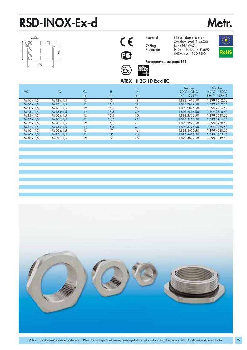
97
H
AG
GL
IG
RSD-INOX-Ex-d
M 16 x 1,5 M 12 x 1,5 12 15 19 1.898.1612.50 1.899.1612.50M 20 x 1,5 M 12 x 1,5 12 15,5 22 1.898.2012.50 1.899.2012.50M 20 x 1,5 M 16 x 1,5 12 15,5 22 1.898.2016.50 1.899.2016.50M 25 x 1,5 M 16 x 1,5 12 15,5 30 1.898.2516.50 1.899.2516.50M 25 x 1,5 M 20 x 1,5 12 15,5 30 1.898.2520.50 1.899.2520.50M 32 x 1,5 M 16 x 1,5 12 16,5 41 1.898.3216.50 1.899.3216.50M 32 x 1,5 M 20 x 1,5 12 16,5 41 1.898.3220.50 1.899.3220.50M 32 x 1,5 M 25 x 1,5 12 16,5 41 1.898.3225.50 1.899.3225.50M 40 x 1,5 M 20 x 1,5 12 17 46 1.898.4020.50 1.899.4020.50M 40 x 1,5 M 25 x 1,5 12 17 46 1.898.4025.50 1.899.4025.50M 40 x 1,5 M 32 x 1,5 12 17 46 1.898.4032.50 1.899.4032.50
Metr.M
RoHS
II 2G 1D Ex d IICATEXNumber Number
AG IG GL H -20 °C – 95 °C -60 °C – 180 °Cmm mm mm (-4 °F – 203°F) (-76 °F – 356°F)
Material Nickel plated brass /Stainless steel (1.4404)
O-Ring Buna-N /VMQProtection IP 68 – 10 bar / IP 69K
(NEMA 6 – 150 PSIG)
For approvals see page 162
Maß- und Konstruktionsänderungen vorbehalten • Dimensions and specifications may be changed without prior notice • Sous réserves de modification de mesure et de construction

98
AG
H
GL
V-Ms-/INOX-Ex-d
V-Ms-Ex-dM 12 x 1,5 ATEX 12 17 14 1.875.1200.50 1.876.1200.50 1.877.1200.50M 16 x 1,5 ATEX 12 16 19 1.875.1600.50 1.876.1600.50 1.877.1600.50M 20 x 1,5 ATEX 12 15,5 22 1.875.2000.50 1.876.2000.50 1.877.2000.50M 25 x 1,5 ATEX 12 15,5 30 1.875.2500.50 1.876.2500.50 1.877.2500.50M 32 x 1,5 ATEX 12 16,5 41 1.875.3200.50 1.876.3200.50 1.877.3200.50M 40 x 1,5 ATEX 12 17 46 1.875.4000.50 1.876.4000.50 1.877.4000.50M 50 x 1,5 ATEX 12 18 55 1.875.5000.50 1.876.5000.50 1.877.5000.50M 63 x 1,5 ATEX 12 18,5 70 1.875.6300.50 1.876.6300.50 1.877.6300.50
V-INOX-Ex-dM 12 x 1,5 ATEX 12 15 14 1.895.1200.50 1.896.1200.50 1.897.1200.50M 16 x 1,5 ATEX 12 15 19 1.895.1600.50 1.896.1600.50 1.897.1600.50M 20 x 1,5 ATEX 12 15,5 22 1.895.2000.50 1.896.2000.50 1.897.2000.50M 25 x 1,5 ATEX 12 15,5 30 1.895.2500.50 1.896.2500.50 1.897.2500.50M 32 x 1,5 ATEX 12 16,5 41 1.895.3200.50 1.896.3200.50 1.897.3200.50M 40 x 1,5 ATEX 12 17 46 1.895.4000.50 1.896.4000.50 1.897.4000.50M 50 x 1,5 ATEX 12 18 55 1.895.5000.50 1.896.5000.50 1.897.5000.50M 63 x 1,5 ATEX 12 18,5 70 1.895.6300.50 1.896.6300.50 1.897.6300.50
Metr.M
RoHS
II 2G 1D Ex d IICATEX
Maß- und Konstruktionsänderungen vorbehalten • Dimensions and constructions are subject to alterations without notice • Sous réserves de modification de mesure et de construction
Number Number NumberAG Ex- GL H -20 °C – 95 °C -20 °C – 180 °C -60 °C – 180 °C
Generation mm mm mm (-4 °F – 203°F) (-4 °F – 356°F) (-76 °F – 356°F)
Material Nickel plated brass /INOX (1.4404)
Protection IP 68 – 10 bar / IP 69K (NEMA 6 – 150 PSIG)
O-Ring Buna-N / FPM / VMQ
For approvals see page 162

99ATEX
HSK-Ex Accessories
Accessories to be used in conjunction with HSK-IndustryStandard liquid tight strain relief fittings
HSK-V-Ex Plugs for strain relief fittings for hazardouslocations
V-Ex Threaded plugs for Ex applications made of nylon 6/6
V-Ms-Ex Threaded plugs for Ex applications made of nickel plated brass
V-Ms-FPM-Ex Threaded plugs for Ex applications made of nickel plated brass
V-Ms-VMQ-Ex Threaded plugs for Ex applications made of nickel plated brass
RSD-Ms-Ex Reducing bushing for Ex applications made of nickel plated brass
V-INOX-Ex Threaded stainless steel plugs for Ex applications.
RSD-INOX-Ex Reducing bushing made of stainless steel for Ex applications.
Setting Standards

100
HSK-V-Ex
d
H
D
h
II 2G 1DATEX
PG 7 M 12 x 1,5 9,5 6,3 11,5 4,5 1.296.0701.11PG 9 M 16 x 1,5 NPT 3/8” 11 7,8 13,5 5,5 1.296.0901.11PG 11 13,5 9,8 14,5 5,5 1.296.1101.11PG 13,5 M 20 x 1,5 NPT 1/2” 16 11,8 18 8 1.296.1301.11PG 16 NPT 1/2”/16 18,5 13,8 19 9 1.296.1601.11PG 21 M 25 x 1,5 NPT 3/4” 22 17,8 22 11 1.296.2101.11PG 29 M 32 x 1,5 NPT 1” NPT 1 1/4” 29 25 25 10 1.296.2901.11PG 36 M 40 x 1,5 NPT 1 1/2” 38 32 28 11 1.296.3601.11PG 42 M 50 x 1,5 43 38 30 12 1.296.4201.11PG 48 M 63 x 1,5 49 44 30 12 1.296.4801.11
Metr./PG/NPTM
RoHS
Maß- und Konstruktionsänderungen vorbehalten • Dimensions and specifications may be changed without prior notice • Sous réserves de modification de mesure et de construction
Fits the Following Sizes D d H h Numbermm mm mm mm
Material ElastomerOperatingTemperature -20 °C – 95 °C (-4 °F – 203 °F)Colors black RAL 9005
EEx e II BVS 03 ATEX E 298
Continuous Temperature rating -40°C – 95°C available upon request
For approvals see page 162

101
M 12 x 1,5 8,5 13 16,5 15 6 1.297.1201.50M 16 x 1,5 8,5 13 20,5 19 8 1.297.1601.50M 20 x 1,5 9 14,5 25,5 24 8 1.297.2001.50M 25 x 1,5 10,5 16 30,5 28 8 1.297.2501.50M 32 x 1,5 11,5 17,5 38 36 8 1.297.3201.50M 40 x 1,5 11,5 18 48 46 8 1.297.4001.50M 50 x 1,5 13,5 20 60 55 8 1.297.5001.50M 63 x 1,5 14,5 21 75 70 8 1.297.6301.50
H
GL
D
AG
Metr.V-ExM
II 2G 1DATEX RoHS
Maß- und Konstruktionsänderungen vorbehalten • Dimensions and specifications may be changed without prior notice • Sous réserves de modification de mesure et de construction
Material PA (Nylon)O-Ring Buna-NProtection IP 68 – 10 bar / IP 69K
(NEMA 6 – 150 PSIG)OperatingTemperature -20 °C – 90 °C (-4 °F – 194 °F)Colors black RAL 9005
For approvals see page 162
AG GL H D Numbermm mm mm mm mm
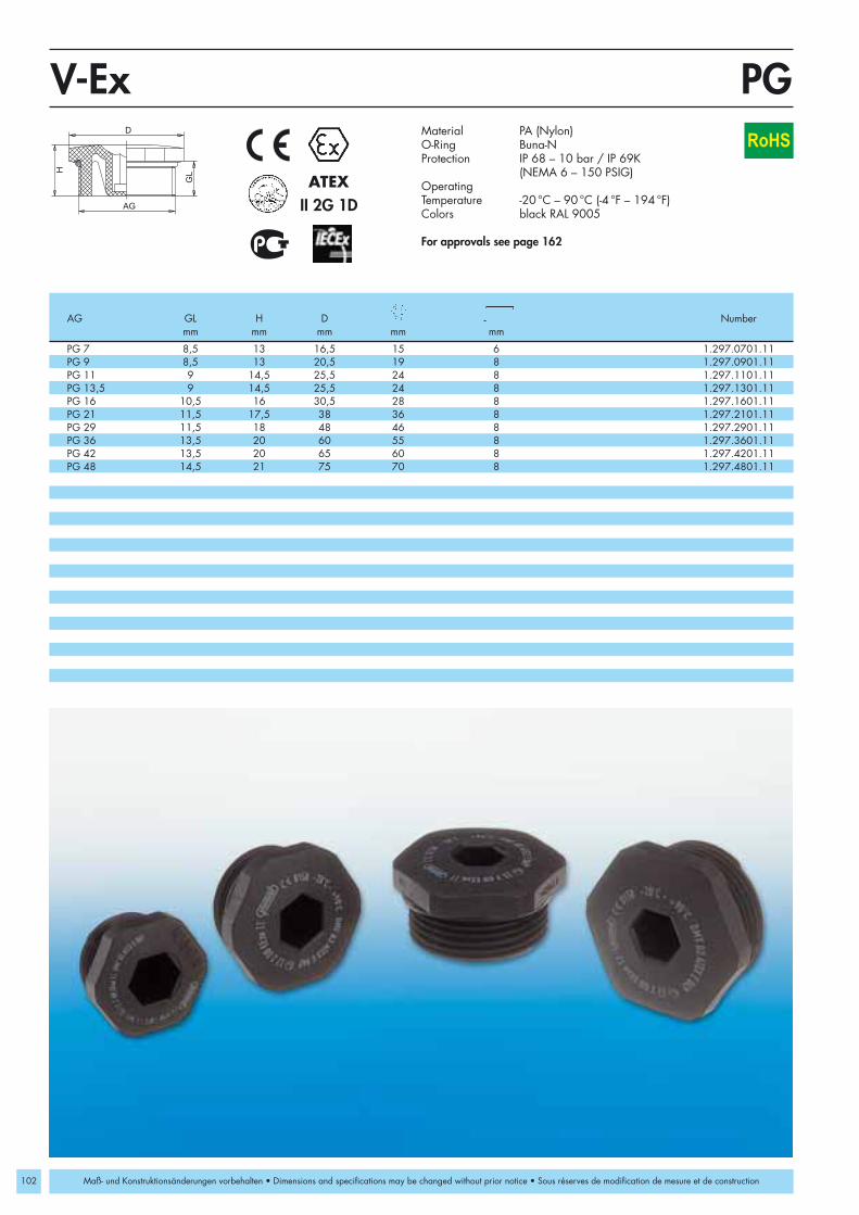
102
PG 7 8,5 13 16,5 15 6 1.297.0701.11PG 9 8,5 13 20,5 19 8 1.297.0901.11PG 11 9 14,5 25,5 24 8 1.297.1101.11PG 13,5 9 14,5 25,5 24 8 1.297.1301.11PG 16 10,5 16 30,5 28 8 1.297.1601.11PG 21 11,5 17,5 38 36 8 1.297.2101.11PG 29 11,5 18 48 46 8 1.297.2901.11PG 36 13,5 20 60 55 8 1.297.3601.11PG 42 13,5 20 65 60 8 1.297.4201.11PG 48 14,5 21 75 70 8 1.297.4801.11
H
GL
D
AG
PGV-Ex
II 2G 1DATEX
RoHS
Maß- und Konstruktionsänderungen vorbehalten • Dimensions and specifications may be changed without prior notice • Sous réserves de modification de mesure et de construction
Material PA (Nylon)O-Ring Buna-NProtection IP 68 – 10 bar / IP 69K
(NEMA 6 – 150 PSIG)OperatingTemperature -20 °C – 90 °C (-4 °F – 194 °F)Colors black RAL 9005
For approvals see page 162
AG GL H D Numbermm mm mm mm mm

M 12 x 1,5 ATEX 6,5 9,5 14 1.197.1200.50 1.198.1200.50 1.199.1200.50M 16 x 1,5 ATEX 6 9 19 1.197.1600.50 1.198.1600.50 1.199.1600.50M 20 x 1,5 ATEX 6 9,5 22 1.197.2000.50 1.198.2000.50 1.199.2000.50M 25 x 1,5 ATEX 7 10,5 30 1.197.2500.50 1.198.2500.50 1.199.2500.50M 32 x 1,5 ATEX 8 12,5 41 1.197.3200.50 1.198.3200.50 1.199.3200.50M 40 x 1,5 ATEX 8 13 46 1.197.4000.50 1.198.4000.50 1.199.4000.50M 50 x 1,5 ATEX 9 15 55 1.197.5000.50 1.198.5000.50 1.199.5000.50M 63 x 1,5 ATEX 10 16,5 70 1.197.6300.50 1.198.6300.50 1.199.6300.50
PG 7 ATEX 5 8 14 1.197.0700.01 1.198.0700.01 1.199.0700.01PG 9 ATEX 6 9 17 1.197.0900.01 1.198.0900.01 1.199.0900.01PG 11 ATEX 6 9,5 20 1.197.1100.01 1.198.1100.01 1.199.1100.01PG 13,5 ATEX 6,5 10 22 1.197.1300.01 1.198.1300.01 1.199.1300.01PG 16 ATEX 6,5 10 24 1.197.1600.01 1.198.1600.01 1.199.1600.01PG 21 ATEX 7 10,5 30 1.197.2100.01 1.198.2100.01 1.199.2100.01PG 29 ATEX 8 12,5 41 1.197.2900.01 1.198.2900.01 1.199.2900.01PG 36 ATEX 8 13 50 1.197.3600.01 1.198.3600.01 1.199.3600.01PG 42 ATEX 9 15 58 1.197.4200.01 1.198.4200.01 1.199.4200.01PG 48 ATEX 10 16,5 65 1.197.4800.01 1.198.4800.01 1.199.4800.01
GL
AG
H
Metr./PGV-Ms-/Ms-FPM-/Ms-VMQ-ExM
103
II 2G 1DATEX RoHS
Maß- und Konstruktionsänderungen vorbehalten • Dimensions and specifications may be changed without prior notice • Sous réserves de modification de mesure et de construction
Material Nickel plated brassProtection IP 68 – 10 bar / IP 69K
(NEMA 6 – 150 PSIG)
V-Ms-Ex O-Ring Buna-N
V-Ms-FPM-ExO-Ring FPM
V-Ms-VMQ-ExO-Ring VMQFor approvals see page 162
V-Ms-Ex V-Ms-FPM-Ex V-Ms-VMQ-ExAG Ex- GL H -20 °C – 95 °C -20 °C – 180 °C -60 °C – 180 °C
Generation mm mm mm (-4 °F – 203°F) (-4 °F – 356°F) (-76 °F – 356°F)
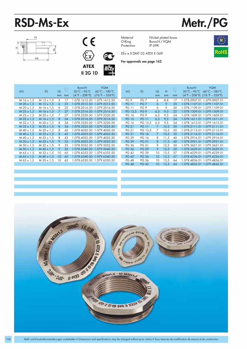
104
AG
IG
GLH
Metr./PGRSD-Ms-ExM
M 16 x 1,5 M 12 x 1,5 5 17 1.078.1612.50 1.079.1612.50 PG 9 PG 7 6 8,8 17 1.078.0907.01 1.079.0907.01M 20 x 1,5 M 12 x 1,5 6 22 1.078.2012.50 1.079.2012.50 PG 11 PG 7 6 9 20 1.078.1107.01 1.079.1107.01M 20 x 1,5 M 16 x 1,5 6 22 1.078.2016.50 1.079.2016.50 PG 11 PG 9 6 9 20 1.078.1109.01 1.079.1109.01M 25 x 1,5 M 16 x 1,5 7 27 1.078.2516.50 1.079.2516.50 PG 13,5 PG 9 6,5 9,5 22 1.078.1309.01 1.079.1309.01M 25 x 1,5 M 20 x 1,5 7 27 1.078.2520.50 1.079.2520.50 PG 16 PG 9 6,5 9,5 24 1.078.1609.01 1.079.1609.01M 32 x 1,5 M 16 x 1,5 8 34 1.078.3216.50 1.079.3216.50 PG 16 PG 11 6,5 9,5 24 1.078.1611.01 1.079.1611.01M 32 x 1,5 M 20 x 1,5 8 34 1.078.3220.50 1.079.3220.50 PG 16 PG 13,5 6,5 9,5 24 1.078.1613.01 1.079.1613.01M 32 x 1,5 M 25 x 1,5 8 34 1.078.3225.50 1.079.3225.50 PG 21 PG 11 7 10,3 30 1.078.2111.01 1.079.2111.01M 40 x 1,5 M 20 x 1,5 8 43 1.078.4020.50 1.079.4020.50 PG 21 PG 13,5 7 10,3 30 1.078.2113.01 1.079.2113.01M 40 x 1,5 M 25 x 1,5 8 43 1.078.4025.50 1.079.4025.50 PG 21 PG 16 7 10,3 30 1.078.2116.01 1.079.2116.01M 40 x 1,5 M 32 x 1,5 8 43 1.078.4032.50 1.079.4032.50 PG 29 PG 16 8 11,5 40 1.078.2916.01 1.079.2916.01M 50 x 1,5 M 25 x 1,5 9 55 1.078.5025.50 1.079.5025.50 PG 29 PG 21 8 11,5 40 1.078.2921.01 1.079.2921.01M 50 x 1,5 M 32 x 1,5 9 55 1.078.5032.50 1.079.5032.50 PG 36 PG 21 9 12,5 50 1.078.3621.01 1.079.3621.01M 50 x 1,5 M 40 x 1,5 9 55 1.078.5040.50 1.079.5040.50 PG 36 PG 29 9 12,5 50 1.078.3629.01 1.079.3629.01M 63 x 1,5 M 32 x 1,5 10 65 1.078.6332.50 1.079.6332.50 PG 42 PG 29 10 13,5 57 1.078.4229.01 1.079.4229.01M 63 x 1,5 M 40 x 1,5 10 65 1.078.6340.50 1.079.6340.50 PG 42 PG 36 10 13,5 57 1.078.4236.01 1.079.4236.01M 63 x 1,5 M 50 x 1,5 10 65 1.078.6350.50 1.079.6350.50 PG 48 PG 36 10 13,5 64 1.078.4836.01 1.079.4836.01
PG 48 PG 42 10 13,5 64 1.078.4842.01 1.079.4842.01
II 2G 1DATEX
RoHS
Maß- und Konstruktionsänderungen vorbehalten • Dimensions and specifications may be changed without prior notice • Sous réserves de modification de mesure et de construction
Material Nickel plated brassO-Ring Buna-N /VQMProtection IP 69K
EEx e II DMT 03 ATEX E 049
For approvals see page 162
Buna-N VQM Buna-N VQMAG IG GL 20°C – 95°C -60°C – 180°C AG IG GL H 20°C – 95°C -60°C – 180°C
mm mm (-4°F – 208°F) (-76 °F – 356°F) mm mm mm (-4°F – 208°F) (-76 °F – 356°F)
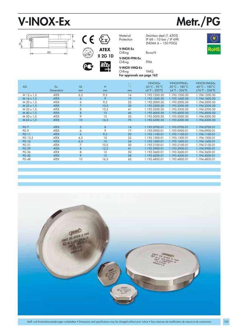
105
M 12 x 1,5 ATEX 6,5 9,5 14 1.192.1200.50 1.193.1200.50 1.194.1200.50M 16 x 1,5 ATEX 6 9 19 1.192.1600.50 1.193.1600.50 1.194.1600.50M 20 x 1,5 ATEX 6 9,5 22 1.192.2000.50 1.193.2000.50 1.194.2000.50M 25 x 1,5 ATEX 7 10,5 30 1.192.2500.50 1.193.2500.50 1.194.2500.50M 32 x 1,5 ATEX 8 12,5 41 1.192.3200.50 1.193.3200.50 1.194.3200.50M 40 x 1,5 ATEX 8 13 46 1.192.4000.50 1.193.4000.50 1.194.4000.50M 50 x 1,5 ATEX 9 15 55 1.192.5000.50 1.193.5000.50 1.194.5000.50M 63 x 1,5 ATEX 10 16,5 70 1.192.6300.50 1.193.6300.50 1.194.6300.50
PG 7 ATEX 5 8 14 1.192.0700.01 1.193.0700.01 1.194.0700.01PG 9 ATEX 6 9 17 1.192.0900.01 1.193.0900.01 1.194.0900.01PG 11 ATEX 6 9,5 20 1.192.1100.01 1.193.1100.01 1.194.1100.01PG 13,5 ATEX 6,5 10 22 1.192.1300.01 1.193.1300.01 1.194.1300.01PG 16 ATEX 6,5 10 24 1.192.1600.01 1.193.1600.01 1.194.1600.01PG 21 ATEX 7 10,5 30 1.192.2100.01 1.193.2100.01 1.194.2100.01PG 29 ATEX 8 12,5 41 1.192.2900.01 1.193.2900.01 1.194.2900.01PG 36 ATEX 8 13 50 1.192.3600.01 1.193.3600.01 1.194.3600.01PG 42 ATEX 9 15 58 1.192.4200.01 1.193.4200.01 1.194.4200.01PG 48 ATEX 10 16,5 65 1.192.4800.01 1.193.4800.01 1.194.4800.01
GL
AG
H
Metr./PGV-INOX-ExM
II 2G 1DATEX RoHS
Maß- und Konstruktionsänderungen vorbehalten • Dimensions and specifications may be changed without prior notice • Sous réserves de modification de mesure et de construction
Material Stainless steel (1.4305)Protection IP 68 – 10 bar / IP 69K
(NEMA 6 – 150 PSIG)
V-INOX-Ex O-Ring Buna-N
V-INOX-FPM-ExO-Ring FPM
V-INOX-VMQ-ExO-Ring VMQFor approvals see page 162
V-INOX-Ex V-INOX-FPM-Ex V-INOX-VMQ-ExAG Ex- GL H -20 °C – 95 °C -20 °C – 180 °C -60 °C – 180 °C
Generation mm mm mm (-4 °F – 203°F) (-4 °F – 356°F) (-76 °F – 356°F)

106
AG
IG
GLH
Metr./PGRSD-INOX-ExM
M 16 x 1,5 M 12 x 1,5 5 17 1.098.1612.50 1.099.1612.50 PG 9 PG 7 6 8,8 17 1.098.0907.01 1.099.0907.01M 20 x 1,5 M 12 x 1,5 6 22 1.098.2012.50 1.099.2012.50 PG 11 PG 7 6 9 20 1.098.1107.01 1.099.1107.01M 20 x 1,5 M 16 x 1,5 6 22 1.098.2016.50 1.099.2016.50 PG 11 PG 9 6 9 20 1.098.1109.01 1.099.1109.01M 25 x 1,5 M 16 x 1,5 7 27 1.098.2516.50 1.099.2516.50 PG 13,5 PG 9 6,5 9,5 22 1.098.1309.01 1.099.1309.01M 25 x 1,5 M 20 x 1,5 7 27 1.098.2520.50 1.099.2520.50 PG 13,5 PG 11 6,5 9,5 22 1.098.1311.01 1.099.1311.01M 32 x 1,5 M 16 x 1,5 8 34 1.098.3216.50 1.099.3216.50 PG 16 PG 9 6,5 9,5 24 1.098.1609.01 1.099.1609.01M 32 x 1,5 M 20 x 1,5 8 34 1.098.3220.50 1.099.3220.50 PG 16 PG 11 6,5 9,5 24 1.098.1611.01 1.099.1611.01M 32 x 1,5 M 25 x 1,5 8 34 1.098.3225.50 1.099.3225.50 PG 16 PG 13,5 6,5 9,5 24 1.098.1613.01 1.099.1613.01M 40 x 1,5 M 20 x 1,5 8 43 1.098.4020.50 1.099.4020.50 PG 21 PG 11 7 10,3 30 1.098.2111.01 1.099.2111.01M 40 x 1,5 M 25 x 1,5 8 43 1.098.4025.50 1.099.4025.50 PG 21 PG 13,5 7 10,3 30 1.098.2113.01 1.099.2113.01M 40 x 1,5 M 32 x 1,5 8 43 1.098.4032.50 1.099.4032.50 PG 21 PG 16 7 10,3 30 1.098.2116.01 1.099.2116.01M 50 x 1,5 M 25 x 1,5 9 55 1.098.5025.50 1.099.5025.50 PG 29 PG 16 8 11,5 40 1.098.2916.01 1.099.2916.01M 50 x 1,5 M 32 x 1,5 9 55 1.098.5032.50 1.099.5032.50 PG 29 PG 21 8 11,5 40 1.098.2921.01 1.099.2921.01M 50 x 1,5 M 40 x 1,5 9 55 1.098.5040.50 1.099.5040.50 PG 36 PG 21 9 12,5 50 1.098.3621.01 1.099.3621.01M 63 x 1,5 M 32 x 1,5 10 65 1.098.6332.50 1.099.6332.50 PG 36 PG 29 9 12,5 50 1.098.3629.01 1.099.3629.01M 63 x 1,5 M 40 x 1,5 10 65 1.098.6340.50 1.099.6340.50 PG 42 PG 29 10 13,5 57 1.098.4229.01 1.099.4229.01M 63 x 1,5 M 50 x 1,5 10 65 1.098.6350.50 1.099.6350.50 PG 42 PG 36 10 13,5 57 1.098.4236.01 1.099.4236.01
PG 48 PG 36 10 13,5 64 1.098.4836.01 1.099.4836.01PG 48 PG 42 10 13,5 64 1.098.4842.01 1.099.4842.01
II 2G 1DATEX
RoHS
Maß- und Konstruktionsänderungen vorbehalten • Dimensions and constructions are subject to alterations without notice • Sous réserves de modification de mesure et de construction
Material Stainless steel (1.4305)O-Ring Buna-N /VQMProtection IP 68 – 10 bar / IP 69K
EEx e II DMT 03 ATEX E 049
For approvals see page 162
Buna-N VQM Buna-N VQMAG IG GL 20°C – 95°C -60°C – 180°C AG IG GL H 20°C – 95°C -60°C – 180°C
mm mm (-4°F – 208°F) (-76 °F – 356°F) mm mm mm (-4°F – 208°F) (-76 °F – 356°F)

107
Miscellaneous strain relief products made of nickel plated brassor nylon 6/6 for general applications and cable diameters ofup to 90mm (3-1/2“).
Miscellaneous Strain Relief Fittings
Setting Standards
SE/ZSE Nickel plated brass grounding strainrelief fittings with flex protection
Z Strain relief fittings with flex protection
WADI-A Nickel plated brass strain relief fittingsfor cable diameters of up to 90mm (3-1/2“)
WADI-A-FPM Nickel plated brass strain relief fittingsfor high temperature applications
DIN 46320 Nylon 6/6 or nickel plated brass strain relief fittings

108
PG 9 7 17 17/15 4 - 10 6 1.680.0906.01 PG 9 7 27 17/ 19 6,5 - 10 6 1.681.0906.01PG 11 7 20 20/18 6,5 - 12 8 1.680.1108.01 PG 11 7 29 20/22 7,5 - 12 7 1.681.1107.01PG 13,5 8 21 22/20 6,5 -13,5 10 1.680.1310.01 PG 11 7 29 20/22 7,5 - 12 8 1.681.1108.01PG 13,5 8 21 22/20 6,5 - 13,5 12 1.680.1312.01 PG 13,5 8 30 22/24 8,5 - 13,5 10 1.681.1310.01PG 16 8 24 24/22 6,5 -16 12 1.680.1612.01 PG 13,5 8 30 22/24 8,5 - 13,5 12 1.681.1312.01PG 16 8 24 24/22 6,5 - 16 14 1.680.1614.01 PG 16 8 31 24/26 10,5 - 16 12 1.681.1612.01PG 21 10 27 30/28 9 - 20 15 1.680.2115.01 PG 16 8 31 24/26 10,5 - 16 14 1.681.1614.01PG 21 10 27 30/28 9 - 20 18 1.680.2118.01 PG 21 10 36 30/33 13 - 20 15 1.681.2115.01PG 29 10 30 40/37 17 - 28 20 1.680.2920.01 PG 21 10 36 30/33 13 - 20 18 1.681.2118.01PG 29 10 30 40/37 17 - 28 24 1.680.2924.01 PG 29 10 40 40/42 19 - 28 20 1.681.2920.01
PG 29 10 40 40/42 19 - 28 24 1.681.2924.01
GLH
E
AG
GLH
AGE
PGSE/ZSERoHS
Maß- und Konstruktionsänderungen vorbehalten • Dimensions and specifications may be changed without prior notice • Sous réserves de modification de mesure et de construction
Type SE Type ZSE
Type SE Type ZSE
Material Nickel plated brassSeal ring Buna-NProtection IP 54
AG GL H E Number AG GL H E Numbermm mm mm mm mm mm mm mm mm mm

M 12 x 1,5 5 22 14/16 6 - 8 1.105.1200.50 1.105.1200.51M 16 x 1,5 5 25 18/19 8 - 10 1.105.1600.50 1.105.1600.51 M 16 x 1,5 5 25 18/19 6,5 - 10 1.105.1600.52M2 0 x 1,5 6 26 22/22 10 - 12 1.105.2000.50 1.105.2000.51 M 20 x 1,5 6 26 22/22 7,5 - 12 1.105.2000.52M 20 x 1,5 6 27,5 22/24 12 - 14 1.105.2013.50 1.105.2013.51 M 20 x 1,5 6 27,5 22/24 8,5 - 13,5 1.105.2013.52M 20 x 1,5 6 28,5 24/26 13 - 15 1.105.2016.50 1.105.2016.51 M 20 x 1,5 6 28,5 24/26 10,5 - 15 1.105.2016.52M 25 x 1,5 6 33 30/33 17 - 19 1.105.2500.50 1.105.2500.51 M 25 x 1,5 6 33 30/33 13 - 20 1.105.2500.52M 32 x 1,5 6 36 39/42 26 - 27 1.105.3200.50 1.105.3200.51 M 32 x 1,5 6 36 39/42 19 - 28 1.105.3200.52M 40 x 1,5 7 41 50/52 33 - 35 1.105.4000.50 1.105.4000.51 M 40 x 1,5 7 41 50/52 24 - 34 1.105.4000.52M 50 x 1,5 8 45 57/59 39 - 41 1.105.5000.50 1.105.5000.51 M 50 x 1,5 8 45 57/59 34 - 40 1.105.5000.52M 63 x 1,5 9 48 66/64 43 - 45 1.105.6300.50 1.105.6300.51 M 63 x 1,5 9 48 66/64 39 - 46 1.105.6300.52
PG 7 5 22 14/16 6 - 8 1.105.0700.01 1.105.0703.01PG 9 6 25 17/19 8 - 10 1.105.0900.01 1.105.0903.01 PG 9 6 25 17/19 6,5 - 10 1.105.0901.01PG 11 6 26 20/22 10 - 12 1.105.1100.01 1.105.1103.01 PG 11 6 26 20/22 7,5 - 12 1.105.1101.01PG 13,5 6,5 27,5 22/24 12 - 14 1.105.1300.01 1.105.1303.01 PG 13,5 6,5 27,5 22/24 8,5 - 13,5 1.105.1301.01PG 16 6,5 28,5 24/26 14 - 16 1.105.1600.01 1.105.1603.01 PG 16 6,5 28,5 24/26 10,5 - 16 1.105.1601.01PG 21 7 33 30/33 17 - 19 1.105.2100.01 1.105.2103.01 PG 21 7 33 30/33 13 - 20 1.105.2101.01PG 29 8 36 40/42 26 - 28 1.105.2900.01 1.105.2903.01 PG 29 8 36 40/42 19 - 28 1.105.2901.01PG 36 9 41 50/52 33 - 35 1.105.3600.01 1.105.3603.01 PG 36 9 41 50/52 24 - 34 1.105.3601.01PG 42 10 45 57/59 39 - 41 1.105.4200.01 1.105.4203.01 PG 42 10 45 57/59 34 - 40 1.105.4201.01PG 48 10 48 64/64 43 - 45 1.105.4800.01 1.105.4803.01 PG 48 10 48 64/64 39 - 46 1.105.4801.01
Metr./PGZM
109
RoHS
Maß- und Konstruktionsänderungen vorbehalten • Dimensions and specifications may be changed without prior notice • Sous réserves de modification de mesure et de construction
Material Nickel plated brassSeal ring DIN 46320-6 Soft rubber /Buna-NorSeal ring DIN 46320-7 Buna-N(multiperforated)Protection IP 54 (NEMA 2),
with thread seal ring IP 65 (NEMA 4x)Operating -20 °C – 60 °C (-4 °F – 140 °F) /Temperature -20 °C – 80 °C (-4 °F – 176 °F) (Buna-N)
AG GL H Number Number AG GL H Numbermm mm mm mm Soft rubber Buna-N mm mm mm mm Buna-N
With seal ring DIN 46320-6 With multiperforated seal ring DIN 46320-7 Buna-N

110
M 12 x 1,5 5 16 14 4 - 6 1.106.1201.50M 16 x 1,5 5 18 18 4 - 9 1.106.1601.50M 20 x 1,5 6 22 22 7 - 13 1.106.2001.50M 25 x 1,5 7 23 28 10 - 18 1.106.2501.50M 32 x 1,5 8 26 35 20 - 24 1.106.3201.50
PG 7 6 16 14 2 - 3 1.106.0701.01 4 - 6,5 1.106.0700.01 6,5 - 8 1.106.0702.01PG 9 6 18 17 4 - 5 1.106.0904.01 5 - 7 1.106.0900.01 7 - 10 1.106.0902.01PG 11 6 18 20 5 - 7 1.106.1101.01 7 - 10 1.106.1103.01 8 - 12 1.106.1100.01PG 13,5 6 21 24 7 - 10 1.106.1303.01 9 - 12 1.106.1300.01 11 - 15 1.106.1304.01PG 16 6 21 24 7 - 10 1.106.1603.01 9 - 12 1.106.1600.01 11 - 15 1.106.1604.01PG 21 7,5 22,5 32 14 - 17 1.106.2102.01 16 - 20,5 1.106.2103.01 19 - 22 1.106.2101.01PG 29 8 24 40 19 - 22,5 1.106.2901.01 20 - 26 1.106.2902.01PG 29 8 24 40 22 - 28 1.106.2903.01 26 - 32 1.106.2904.01
PG 11 * 6 18 20 5 - 12 1.106.1104.01PG 11 * 6 21 24 8 - 15 1.106.1105.01PG 13,5 * 6 21 24 8 - 15 1.106.1301.01PG 16 * 6 21 24 8 - 15 1.106.1601.01PG 21 * 7,5 22,5 32 11 - 20,5 1.106.2100.01PG 29 * 8 24 40 18 - 26 1.106.2900.01PG 36 * 8 29 50 25 - 35 1.106.3600.01PG 42 * 10 30 58 35 - 45 1.106.4200.01PG 48 * 11 33 64 38 - 49 1.106.4800.01
Metr./PGWADI-AM
RoHS
Maß- und Konstruktionsänderungen vorbehalten • Dimensions and specifications may be changed without prior notice • Sous réserves de modification de mesure et de construction
Material Nickel plated brassSeal ring Buna-NO-Ring Buna-NProtection IP 66 Operating -20 °C – 100 °C (-4 °F – 212 °F)Temperature short time exposure 130 °C (266 °F)
* Two piece sealing insert
AG GL H Number Number Numbermm mm mm mm mm mm
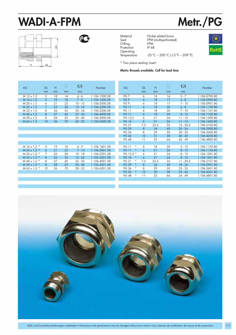
M 12 x 1,5 5 18 14 4 - 6 1.106.1200.58 PG 7 6 16 14 5 - 7 1.106.0700.80M 16 x 1,5 5 19 18 7 - 9 1.106.1600.58 PG 9 6 18 17 6 - 8 1.106.0900.80M 20 x 1,5 6 21 22 10 - 13 1.106.2000.58 PG 9 6 18 17 7 - 10 1.106.0901.80M 25 x 1,5 7 23 28 15 - 18 1.106.2500.58 PG 11 6 18 20 6 - 8 1.106.1100.80M 32 x 1,5 8 26 35 20 - 24 1.106.3200.58 PG 11 6 18 20 7 - 10 1.106.1101.80M 40 x 1,5 8 27 45 27 - 32 1.106.4000.58 PG 11 6 18 20 8 - 12 1.106.1102.80M 50 x 1,5 8 28 55 35 - 40 1.106.5000.58 PG 13,5 6 21 24 11 - 15 1.106.1300.80M 63 x 1,5 10 36 70 45 - 52 1.106.6300.58 PG 16 6 21 24 11 - 15 1.106.1600.80
PG 21 7,5 22,5 32 15 - 20,5 1.106.2100.80PG 29 8 24 40 20 - 26 1.106.2900.80PG 36 8 29 50 30 - 35 1.106.3600.80PG 42 10 31 58 40 - 45 1.106.4200.80PG 48 11 33 64 42 - 49 1.106.4800.80
M 16 x 1,5 * 5 19 18 4 - 9 1.106.1601.58 PG 11 * 6 18 20 5 - 12 1.106.1103.80M 20 x 1,5 * 6 21 22 7 - 13 1.106.2001.58 PG 11 * 6 21 24 8 - 15 1.106.1104.80M 25 x 1,5 * 7 23 28 10 - 18 1.106.2501.58 PG 13,5 * 6 21 24 8 - 15 1.106.1301.80M 32 x 1,5 * 8 26 35 16 - 24 1.106.3201.58 PG 16 * 6 21 24 8 - 15 1.106.1601.80M 40 x 1,5 * 8 27 45 22 - 32 1.106.4001.58 PG 21 * 7,5 22,5 32 11 - 20,5 1.106.2101.80M 50 x 1,5 * 8 28 55 30 - 40 1.106.5001.58 PG 29 * 8 24 40 18 - 26 1.106.2901.80M 63 x 1,5 * 10 36 70 38 - 52 1.106.6301.58 PG 36 * 8 29 50 25 - 35 1.106.3601.80
PG 42 * 10 30 58 35 - 45 1.106.4201.80PG 48 * 11 33 64 34 - 49 1.106.4801.80
Metr./PGWADI-A-FPM
111
M
RoHS
Maß- und Konstruktionsänderungen vorbehalten • Dimensions and specifications may be changed without prior notice • Sous réserves de modification de mesure et de construction
Material Nickel plated brassSeal FPM (multiperforated)O-Ring FPMProtection IP 68OperatingTemperature -25 °C – 200 °C (-13 °F – 209 °F)
* Two piece sealing insert
Metric threads available. Call for lead time
AG GL H Number AG GL H Numbermm mm mm mm mm mm mm mm

112
G 2 1/2” 18 55 90 48 - 55 1.106.5200.01G 2 1/2” 18 55 90 53 - 60 1.106.5201.01G 3” 18 55 100 58 - 65 1.106.3000.01G 3” 18 55 105 63 - 70 1.106.3001.01G 4” 22 65 125 68 - 75 1.106.4000.01G 4” 22 65 125 73 - 80 1.106.4001.01G 4” 22 65 125 78 - 85 1.106.4002.01G 4” 22 65 130 83 - 90 1.106.4003.01
G 2 1/2” 7 80 1.106.5200.99G 3” 8 95 1.106.3000.99G 4” 11 125 1.106.4000.99
GWADI-ARoHS
Maß- und Konstruktionsänderungen vorbehalten • Dimensions and specifications may be changed without prior notice • Sous réserves de modification de mesure et de construction
Lock nut GR
Material Nickel plated brassSeal Buna-NProtection IP 68OperatingTemperature -20 °C – 100 °C (-4 °F – 212 °F)
Lock nut GRMaterial Nickel plated brass
AG GL H Numbermm mm mm mm

PG 7 8 20 15/13 3,5 - 6 1.201.0700.10 1.202.0700.11PG 9 8 21 19/16 4,5 - 7 1.201.0900.10 1.202.0900.11 PG 9 8 21 19/16 4 - 10 1.201.0902.10 1.202.0901.11PG 11 8 22 22/19 6 - 9 1.201.1100.10 1.202.1100.11 PG 11 8 22 22/19 6,5 - 12 1.201.1102.10 1.202.1101.11PG 13,5 9 26 24/21 9 - 12 1.201.1300.10 1.202.1300.11 PG 13,5 9 26 24/21 6,5 - 13,5 1.201.1302.10 1.202.1301.11PG 16 10 28 27/23 11 - 14 1.201.1600.10 1.202.1600.11 PG 16 10 28 27/23 6,5 - 16 1.201.1602.10 1.202.1601.11PG 21 11 32 33/30 14 - 18 1.201.2100.10 1.202.2100.11 PG 21 11 32 33/30 9 - 20 1.201.2102.10 1.202.2101.11PG 29 11 35 42/40 18 - 25 1.201.2900.10 1.202.2900.11 PG 29 11 35 42/40 17 - 28 1.201.2902.10 1.202.2901.11PG 36 13 39 53/50 25 - 32 1.201.3600.10 1.202.3600.11 PG 36 13 39 53/50 23 - 34 1.201.3602.10 1.202.3601.11PG 42 13 44 60/55 30 - 38 1.201.4200.10 1.202.4200.11 PG 42 13 44 60/55 29 - 40 1.201.4202.10 1.202.4201.11PG 48 14 44 65/60 34 - 42 1.201.4800.10 1.202.4800.11 PG 48 14 44 65/60 35 - 46 1.201.4802.10 1.202.4801.11
PGDIN 46320-A-FS
113
RoHS
Maß- und Konstruktionsänderungen vorbehalten • Dimensions and specifications may be changed without prior notice • Sous réserves de modification de mesure et de construction
Material SB /PA (Nylon)Seal ring Nr. 6 Soft rubber /Buna-NorSeal ring Nr. 7 Soft rubber /Buna-N (multiperforated)Protection IP 54, with thread seal ring IP 65Operating -20 °C – 60 °C (-4 °F – 140 °F) /Temperature -20 °C – 80 °C (-4 °F – 176 °F) (Buna-N)Colors grey RAL 7035
Metric threads available upon request
AG GL H Number Number AG GL H Number Numbermm mm mm mm SB PA mm mm mm mm SB PA
With seal ring Nr. 6 With multiperforated seal ring Nr. 7

114
PGDIN 46320-C4-Ms
PG 7 5 15 14/13 6 - 8 1.101.0700.01 1.101.0703.01PG 9 6 15 17/15 8 - 10 1.101.0900.01 1.101.0903.01 PG 9 6 15 17/15 4 - 10 1.101.0901.01PG 11 6 17 20/18 10 - 12 1.101.1100.01 1.101.1103.01 PG 11 6 17 20/18 6,5 - 12 1.101.1101.01PG 13,5 6,5 20 22/20 12 - 14 1.101.1300.01 1.101.1303.01 PG 13,5 6,5 20 22/20 6,5 - 13,5 1.101.1301.01PG 16 6,5 22 24/22 14 - 16 1.101.1600.01 1.101.1603.01 PG 16 6,5 22 24/22 6,5 - 16 1.101.1601.01PG 21 7 24 30/28 17 - 19 1.101.2100.01 1.101.2103.01 PG 21 7 24 30/28 9 - 20 1.101.2101.01PG 29 8 26 40/37 18 - 25 1.101.2900.01 1.101.2903.01 PG 29 8 26 40/37 17 - 28 1.101.2901.01PG 36 9 30 50/47 33 - 35 1.101.3600.01 1.101.3603.01 PG 36 9 30 50/47 23 - 34 1.101.3601.01PG 42 10 34 57/54 39 - 41 1.101.4200.01 1.101.4203.01 PG 42 10 34 57/54 29 - 40 1.101.4201.01PG 48 10 37 64/60 45 - 47 1.101.4800.01 1.101.4803.01 PG 48 10 37 64/60 35 - 46 1.101.4801.01
RoHS
Maß- und Konstruktionsänderungen vorbehalten • Dimensions and specifications may be changed without prior notice • Sous réserves de modification de mesure et de construction
Material Nickel plated brassSeal ring Nr. 6 Soft rubber orSeal ring Nr. 7 Buna-N(multiperforated)Protection IP 54, with thread seal ring IP 65Operating -20 °C – 60 °C (-4 °F – 140 °F) (SBR)Temperature -20 °C – 80 °C (-4 °F – 176 °F) (Buna-N)
Elongated thread availableMetric threads available upon request
AG GL H Number Number AG GL H Numbermm mm mm mm SBR NBR mm mm mm mm Buna-N
With seal ring Nr. 6 With multiperforated seal ring Nr. 7

115
Miscellaneous accessories such as lock nuts, plugs, adapters,etc. made of nickel plated brass, stainless steel or plastic
GM-FS/Ms Lock nuts made of plastic or nickel plated brass
V-N-FS/Ms Dome plugs made of plastic and nickelplated brass
V-NE/Ms Dome plugs made of plastic or nickel plated brass
V-INOX Dome plugs made of stainless steel
R-FS/H Reducers made of plastic or nickel platedbrass
R-M-PA Metric reducers and adapters made of plastic
RS-Ms/RSD-Ms Metric reducers and adapters made of nickel plated brass
RS-INOX/ Reducing bushing made of stainless steelRSD-INOX
E-M-PA Metric enlargers and adapters made of plastic
E-Ms/E-K Metric enlargers and adapters made ofplastic or nickel plated brass
RE-Ms Adapters made of nickel plated brass
DS/WN Plastic plugs and threaded nipples
O-Ring Made of Buna-N or FPM
Thread Seal Ring Made of Polyethylen or fiber-reinforced plastic
KLE High performance clamp with flex protection
90° Snap Elbow Made of nylon 6/6
KF-G Snap flange made of nylon 6/6
FW-ZN/T Flange elbow made of plastic or zinc die casting
Cable Ties Made of nylon 6/6
Accessories and Parts
Setting Standards

116
M 12 x 1,5 5 17 1.262.1200.50 1.262.1201.50M 16 x 1,5 5 22 1.262.1600.50 1.262.1601.50M 20 x 1,5 6 27 1.262.2000.50 1.262.2001.50M 25 x 1,5 7 36 1.262.2500.50 1.262.2501.50M 32 x 1,5 7 41 1.262.3200.50 1.262.3201.50M 40 x 1,5 7 50 1.262.4000.50 1.262.4001.50M 50 x 1,5 8 60 1.262.5000.50 1.262.5001.50M 63 x 1,5 8 75 1.262.6300.50 1.262.6301.50
PG 7 5 19 1.261.0700.10 1.262.0700.11 1.262.0701.11PG 9 5 22 1.261.0900.10 1.262.0900.11 1.262.0901.11PG 11 5 24 1.261.1100.10 1.262.1100.11 1.262.1101.11PG 13,5 6 27 1.261.1300.10 1.262.1300.11 1.262.1301.11PG 16 6 30 1.261.1600.10 1.262.1600.11 1.262.1601.11PG 21 7 36 1.261.2100.10 1.262.2100.11 1.262.2101.11PG 29 7 46 1.261.2900.10 1.262.2900.11 1.262.2901.11PG 36 8 60 1.261.3600.10 1.262.3600.11 1.262.3601.11PG 42 8 65 1.261.4200.10 1.262.4200.11 1.262.4201.11PG 48 8 70 1.261.4800.10 1.262.4800.11 1.262.4801.11
3/8" NPT 7 24 1.262.3800.70 1.262.3801.701/2" NPT 6 27 1.262.1200.70 1.262.1201.703/4" NPT 7 32 1.262.3400.70 1.262.3401.701" NPT 7 40 1.262.1000.70 1.262.1001.70
Metr./PG/NPTGM-FSM
RoHS
Maß- und Konstruktionsänderungen vorbehalten • Dimensions and specifications may be changed without prior notice • Sous réserves de modification de mesure et de construction
Material SB /PA (Nylon)Operating -20 °C – 40 °C (-4 °F –104 °F) (SB)Temperature -40 °C – 100 °C (-40 °F – 212 °F) (PA)Colors grey RAL 7035
black RAL 9005
Number Number NumberIG H SB PA PA
mm mm grey grey black

M 12 x 1,5 2,8 15 1.161.1200.50 3 17 1.161.1200.58M 16 x 1,5 2,8 19 1.161.1600.50 3 19 1.161.1600.58M 20 x 1,5 3,0 23 1.161.2000.50 3 24 1.161.2000.58M 25 x 1,5 3,5 29 1.161.2500.50 4 27 1.161.2500.58M 32 x 1,5 4,0 36 1.161.3200.50 5 36 1.161.3200.58M 40 x 1,5 4,5 45 1.161.4000.50 5 46 1.161.4000.58M 50 x 1,5 5,5 55 1.161.5000.50 5 55 1.161.5000.58M 63 x 1,5 6,0 70 1.161.6300.50 6 70 1.161.6300.58
PG 7 2,8 15 1.161.0700.01 2,8 17 1.161.0700.08PG 9 2,8 18 1.161.0900.01 2,8 22 1.161.0900.08PG 11 3,0 21 1.161.1100.01 3 22 1.161.1100.08PG 13,5 3,0 23 1.161.1300.01 3 24 1.161.1300.08PG16 3,0 26 1.161.1600.01 3 27 1.161.1600.08PG 21 3,5 32 1.161.2100.01 3,5 32 1.161.2100.08PG 29 4,0 41 1.161.2900.01 4 41 1.161.2900.08PG 36 5,0 51 1.161.3600.01 5 50 1.161.3600.08PG 42 5,0 60 1.161.4200.01PG 48 5,5 64 1.161.4800.01
Metr./PGGM-Ms/GM-INOXM
117
RoHS
Maß- und Konstruktionsänderungen vorbehalten • Dimensions and specifications may be changed without prior notice • Sous réserves de modification de mesure et de construction
Material Nickel plated brassINOX (1.4305)
Further sizes upon request
IG H Number H Numbermm mm Ms mm mm INOX

118
M 12 x 1,5 6 10 15 1.251.1200.50 1.251.1201.50M 16 x 1,5 7 11,5 20 1.251.1600.50 1.251.1601.50M 20 x 1,5 6 9,5 25 1.251.2000.50 1.251.2001.50M 25 x 1,5 11 15,5 30 1.251.2500.50 1.251.2501.50M 32 x 1,5 11 16 38 1.251.3200.50 1.251.3201.50M 40 x 1,5 13 18 46 1.251.4000.50 1.251.4001.50M 50 x 1,5 13 18,5 56 1.251.5000.50 1.251.5001.50M 63 x 1,5 15 19 69 1.251.6300.50 1.251.6301.50
PG 7 6 8 15 1.252.0700.10 1.251.0700.11 1.251.0701.11PG 9 6 9 19 1.252.0900.10 1.251.0900.11 1.251.0901.11PG 11 6 9 22 1.252.1100.10 1.251.1100.11 1.251.1101.11PG 13,5 6 9,5 25 1.252.1300.10 1.251.1300.11 1.251.1301.11PG 16 6 9,5 27 1.252.1600.10 1.251.1600.11 1.251.1601.11PG 21 8 11 33 1.252.2100.10 1.251.2100.11 1.251.2101.11PG 29 8 12 44 1.252.2900.10 1.251.2900.11 1.251.2901.11PG 36 10 15 55 1.252.3600.10 1.251.3600.11 1.251.3601.11PG 42 10 16 62 1.252.4200.10 1.251.4200.11 1.251.4201.11PG 48 12 16 69 1.252.4800.10 1.251.4800.11 1.251.4801.11
D AG
GL
H
Metr./PGV-N-FSM
RoHS
Maß- und Konstruktionsänderungen vorbehalten • Dimensions and specifications may be changed without prior notice • Sous réserves de modification de mesure et de construction
Material SB /PA (Nylon)Protection IP 54Operating -20 °C – 70 °C (-4 °F – 158 °F) (SB)Temperature -40 °C – 100 °C (-40 °F – 212 °F) (PA)Colors grey RAL 7035
black RAL 9005
Other colos available upon request
Number Number NumberAG GL H D SB PA PA
mm mm mm grey grey black

M 12 x 1,5 5 7,5 14 1.052.1200.50 M 12 x 1,5 6,5 9,5 14 1.052.1201.50M 16 x 1,5 5 9,0 18 1.052.1600.50 M 16 x 1,5 6 9 20 1.052.1601.50M 20 x 1,5 6,5 9,5 22 1.052.2000.50 M 20 x 1,5 6,5 9,5 24 1.052.2001.50M 25 x 1,5 7 11,0 28 1.052.2500.50 M 25 x 1,5 7 11 28 1.052.2501.50M 32 x 1,5 8 12,0 35 1.052.3200.50 M 32 x 1,5 8 12,5 35 1.052.3201.50M 40 x 1,5 8,5 13,0 44 1.052.4000.50 M 40 x 1,5 8 12 45 1.052.4001.50M 50 x 1,5 9 15,0 54 1.052.5000.50 M 50 x 1,5 9 15 55 1.052.5001.50M 63 x 1,5 10 16,0 67 1.052.6300.50 M 63 x 1,5 10 16 68 1.052.6301.50
PG 7 5 8 14 1.052.0700.01 PG 7 4,8 8 14 1.052.0701.01PG 9 6 9 17 1.052.0900.01 PG 9 5,5 9 17 1.052.0901.01PG 11 6 9 20 1.052.1100.01 PG 11 5,5 9 20 1.052.1101.01PG 13,5 6,5 9,5 22 1.052.1300.01 PG 13,5 6 9,5 22 1.052.1301.01PG 16 6,5 9,5 24 1.052.1600.01 PG 16 6 9,5 24 1.052.1601.01PG 21 7 11 30 1.052.2100.01 PG 21 6,5 11 30 1.052.2101.01PG 29 8 12 39 1.052.2900.01 PG 29 7,5 12 39 1.052.2901.01PG 36 9 15 50 1.052.3600.01 PG 36 9 15 50 1.052.3601.01PG 42 10 16 57 1.052.4200.01 PG 42 10 16 57 1.052.4201.01PG 48 10 16 64 1.052.4800.01 PG 48 10 16 64 1.052.4801.01
D AG
GL
H
Metr./PGV-N-MsM
V-N-Ms V-N-Ms-SD
119
RoHS
Maß- und Konstruktionsänderungen vorbehalten • Dimensions and specifications may be changed without prior notice • Sous réserves de modification de mesure et de construction
V-N-MsMaterial Nickel plated brassProtection IP 54 (NEMA 2)
V-N-Ms-SDMaterial Nickel plated brassO-Ring Buna-N Protection IP 68OperatingTemperature -40°C – 80°C (-40°F – 176°F)
AG GL H D Number AG GL H D Numbermm mm mm mm mm mm

120
M 12 x 1,5 8,5 13 16,5 15 6 1.255.1201.50 1.256.1201.50M 16 x 1,5 8,5 13 20,5 19 8 1.255.1601.50 1.256.1601.50M 20 x 1,5 9 14,5 25,5 24 8 1.255.2001.50 1.256.2001.50M 25 x 1,5 10,5 16 30,5 28 8 1.255.2501.50 1.256.2501.50M 32 x 1,5 11,5 17,5 38 36 8 1.255.3201.50 1.256.3201.50M 40 x 1,5 11,5 18 48 46 8 1.255.4001.50 1.256.4001.50M 50 x 1,5 13,5 20 60 55 8 1.255.5001.50 1.256.5001.50M 63 x 1,5 14,5 21 75 70 8 1.255.6301.50 1.256.6301.50
PG 7 8,5 13 16,5 15 6 1.255.0701.11 1.256.0701.11PG 9 8,5 13 20,5 19 8 1.255.0901.11 1.256.0901.11PG 11 9 14,5 25,5 24 8 1.255.1101.11 1.256.1101.11PG 13,5 9 14,5 25,5 24 8 1.255.1301.11 1.256.1301.11PG 16 10,5 16 30,5 28 8 1.255.1601.11 1.256.1601.11PG 21 11,5 17,5 38 36 8 1.255.2101.11 1.256.2101.11PG 29 11,5 18 48 46 8 1.255.2901.11 1.256.2901.11PG 36 13,5 20 60 55 8 1.255.3601.11 1.256.3601.11PG 42 13,5 20 65 60 8 1.255.4201.11 1.256.4201.11PG 48 14,5 21 75 70 8 1.255.4801.11 1.256.4801.11
H
GL
D
AG
Metr./PGV-NEM
RoHS
Maß- und Konstruktionsänderungen vorbehalten • Dimensions and specifications may be changed without prior notice • Sous réserves de modification de mesure et de construction
V-NEMaterial PA (Nylon)Protection IP 54 (NEMA 2)Operating Temperature -20 °C – 80 °C (-4 °F – 176 °F)
V-NE-SDMaterial PA (Nylon)O-Ring Buna-N (NE-SD)Protection IP 68 – 10 bar (NE-SD) / IP 69K
(NEMA 6 – 150 PSIG) Operating Temperature -20 °C – 80 °C (-4 °F – 176 °F)Colors black RAL 9005
AG GL H D Number Numbermm mm mm mm mm V-NE V-NE-SD

M 12 x 1,5 6,5 9,5 14 1.155.1200.50 1.156.1200.50 1.157.1200.50M 16 x 1,5 6 9 19 1.155.1600.50 1.156.1600.50 1.157.1600.50M 20 x 1,5 6 9,5 22 1.155.2000.50 1.156.2000.50 1.157.2000.50M 25 x 1,5 7 10,5 30 1.155.2500.50 1.156.2500.50 1.157.2500.50M 32 x 1,5 8 12,5 41 1.155.3200.50 1.156.3200.50 1.157.3200.50M 40 x 1,5 8 13 46 1.155.4000.50 1.156.4000.50 1.157.4000.50M 50 x 1,5 9 15 55 1.155.5000.50 1.156.5000.50 1.157.5000.50M 63 x 1,5 10 16,5 70 1.155.6300.50 1.156.6300.50 1.157.6300.50
PG 7 5 8 14 1.155.0700.01 1.156.0700.01 1.157.0700.01PG 9 6 9 17 1.155.0900.01 1.156.0900.01 1.157.0900.01PG 11 6 9,5 20 1.155.1100.01 1.156.1100.01 1.157.1100.01PG 13,5 6,5 10 22 1.155.1300.01 1.156.1300.01 1.157.1300.01PG 16 6,5 10 24 1.155.1600.01 1.156.1600.01 1.157.1600.01PG 21 7 10,5 30 1.155.2100.01 1.156.2100.01 1.157.2100.01PG 29 8 12,5 41 1.155.2900.01 1.156.2900.01 1.157.2900.01PG 36 8 13 50 1.155.3600.01 1.156.3600.01 1.157.3600.01PG 42 9 15 58 1.155.4200.01 1.156.4200.01 1.157.4200.01PG 48 10 16,5 65 1.155.4800.01 1.156.4800.01 1.157.4800.01
GL
AG
H
Metr./PGV-NE-MsM
121
RoHS
Maß- und Konstruktionsänderungen vorbehalten • Dimensions and specifications may be changed without prior notice • Sous réserves de modification de mesure et de construction
V-NE-MsMaterial Nickel plated brassProtection IP 54 (NEMA 2)
V-NE-Ms-SD/V-NE-Ms-SD-FPM Material Nickel plated brassProtection IP 68 – 10 bar / IP 69K (NE-SD) (NEMA 6 – 150 PSIG)O-Ring Buna-N (NE-SD) / FPMOperating -40 °C – 100 °C (-40 °F – 212 °F)Temperature -40 °C – 200 °C (-40 °F – 382 °F)
NPT threads available upon request
V-NE-Ms V-NE-Ms-SD V-NE-Ms-SD-FPMAG GL H without O-Ring -20 °C – 95 °C -20 °C – 180 °C
mm mm mm (-4 °F – 203°F) (-4 °F – 356°F)

122
M 12 x 1,5 6,5 9,5 14 1.152.1200.50 1.153.1200.50 1.154.1200.50M 16 x 1,5 6 9 19 1.152.1600.50 1.153.1600.50 1.154.1600.50M 20 x 1,5 6 9,5 22 1.152.2000.50 1.153.2000.50 1.154.2000.50M 25 x 1,5 7 10,5 30 1.152.2500.50 1.153.2500.50 1.154.2500.50M 32 x 1,5 8 12,5 41 1.152.3200.50 1.153.3200.50 1.154.3200.50M 40 x 1,5 8 13 46 1.152.4000.50 1.153.4000.50 1.154.4000.50
PG 7 5 8 14 1.152.0700.01 1.153.0700.01 1.154.0700.01PG 9 6 9 17 1.152.0900.01 1.153.0900.01 1.154.0900.01PG 11 6 9,5 20 1.152.1100.01 1.153.1100.01 1.154.1100.01PG 13,5 6,5 10 22 1.152.1300.01 1.153.1300.01 1.154.1300.01PG 16 6,5 10 24 1.152.1600.01 1.153.1600.01 1.154.1600.01PG 21 7 10,5 30 1.152.2100.01 1.153.2100.01 1.154.2100.01PG 29 8 12,5 41 1.152.2900.01 1.153.2900.01 1.154.2900.01PG 36 8 13 50 1.152.3600.01 1.153.3600.01 1.154.3600.01
Metr./PGV-INOXM
GL
AG
H
RoHS
Maß- und Konstruktionsänderungen vorbehalten • Dimensions and constructions are subject to alterations without notice • Sous réserves de modification de mesure et de construction
Material INOX (1.4305)Protection IP 68 – 10 bar / IP 69K
(NEMA 6 – 150 PSIG)O-Ring Buna-N / FPM / VMQ
Number Number NumberAG GL H -20 °C – 95 °C -20 °C – 180 °C -60 °C – 180 °C
mm mm mm (-4 °F – 203°F) (-4 °F – 356°F) (-76 °F – 356°F)

123
M 16 x 1,5 M 12 x 1,5 B 8 6 10 20 1.273.1612.50M 20 x 1,5 M 16 x 1,5 B 8 6 13,5 25 1.273.2016.50M 25 x 1,5 M 20 x 1,5 B 8 6 18 29 1.273.2520.50M 32 x 1,5 M 25 x 1,5 B 10 6 23 36 1.273.3225.50M 40 x 1,5 M 32 x 1,5 C 15 5 30 1.273.4032.50M 50 x 1,5 M 40 x 1,5 C 15 5 38 1.273.5040.50M 63 x 1,5 M 50 x 1,5 C 15 5 48 1.273.6350.50
M 25 x 1,5 PG 13,5 B 8 6 18 29 1.273.2513.50M 25 x 1,5 PG 16 A 8 14 18 29 1.273.2516.50M 32 x 1,5 PG 21 A 10 15 25 36 1.273.3221.50M 40 x 1,5 PG 29 A 10 15 33 45 1.273.4029.50M 50 x 1,5 PG 36 A 12 17 43 55 1.273.5036.50M 63 x 1,5 PG 42 C 15 5 52 1.273.6342.50
PG 9 M 12 x 1,5 C 15 19 8,5 1.273.0912.11PG 11 M 16 x 1,5 C 15 19 11,5 1.273.1116.11PG 13,5 M 16 x 1,5 B 8 6 14 25 1.273.1316.11PG 16 M 20 x 1,5 A 8 13 16 27 1.273.1620.11PG 21 M 25 x 1,5 C 15 19 20,5 1.273.2125.11PG 29 M 32 x 1,5 C 15 19 28 1.273.2932.11PG 36 M 40 x 1,5 C 15 5 38 1.273.3640.11PG 42 M 40 x 1,5 C 15 5 38 1.273.4240.11PG 48 M 50 x 1,5 C 15 5 38 1.273.4850.11
Metr./PGR-M-PAM
IG
H GL
D AG
IG
H GL
D AG
H GL
D AG
IG
RoHS
Maß- und Konstruktionsänderungen vorbehalten • Dimensions and constructions are subject to alterations without notice • Sous réserves de modification de mesure et de construction
Type A Type B Type C Material PA (Nylon)OperatingTemperature -20 °C – 80 °C (-4 °F – 176 °F)Colors black RAL 9005
AG IG Type GL H D Numbermm mm mm mm

124
M 16 x 1,5 M 12 x 1,5 9 27 22 20 B 1.272.1612.50M 20 x 1,5 M 16 x 1,5 9 27 27 24 B 1.272.2016.50M 25 x 1,5 M 20 x 1,5 10 17 32 29 A 1.272.2520.50M 32 x 1,5 M 25 x 1,5 12 19 40 36 A 1.272.3225.50M 40 x 1,5 M 32 x 1,5 12 19 51 46 A 1.272.4032.50M 50 x 1,5 M 40 x 1,5 14 21 61 55 A 1.272.5040.50M 63 x 1,5 M 50 x 1,5 15 22 75 68 A 1.272.6350.50
PG 13,5 PG 9 8 12 27 A 1.271.1309.10 1.272.1309.11PG 16 PG 9 10 13 29 A 1.271.1609.10 1.272.1609.11PG 16 PG 11 10 13 29 A 1.271.1611.10 1.272.1611.11PG 21 PG 13,5 11 13,5 36 A 1.271.2113.10 1.272.2113.11PG 21 PG 16 11 13,5 36 A 1.271.2116.10 1.272.2116.11PG 29 PG 21 11 13,5 46 A 1.271.2921.10 1.272.2921.11PG 36 PG 29 11 15 58 A 1.271.3629.10 1.272.3629.11
PG 9 PG 7 8 14 19 B 1.235.0907.10 1.236.0907.11PG 11 PG 9 8 18 22,5 B 1.235.1109.10 1.236.1109.11PG 13,5 PG 11 9 21 25,5 B 1.235.1311.10 1.236.1311.11PG 16 PG 13,5 10 25 28,5 B 1.235.1613.10 1.236.1613.11
H
GL
D
AGIG
AG
GL
H
IG
Metr./PGR-FSM
RoHS
Maß- und Konstruktionsänderungen vorbehalten • Dimensions and specifications may be changed without prior notice • Sous réserves de modification de mesure et de construction
Reducing intermediate connector
Material SBPA (Nylon)
Operating -20 °C – 70 °C (-4 °F – 158 °F) (SB)Temperature -40°C – 80°C (-40°F – 176°F) (PA)Colors grey RAL 7035
AG IG GL H D Type Number Number mm mm mm mm SB PA
Type A Type B
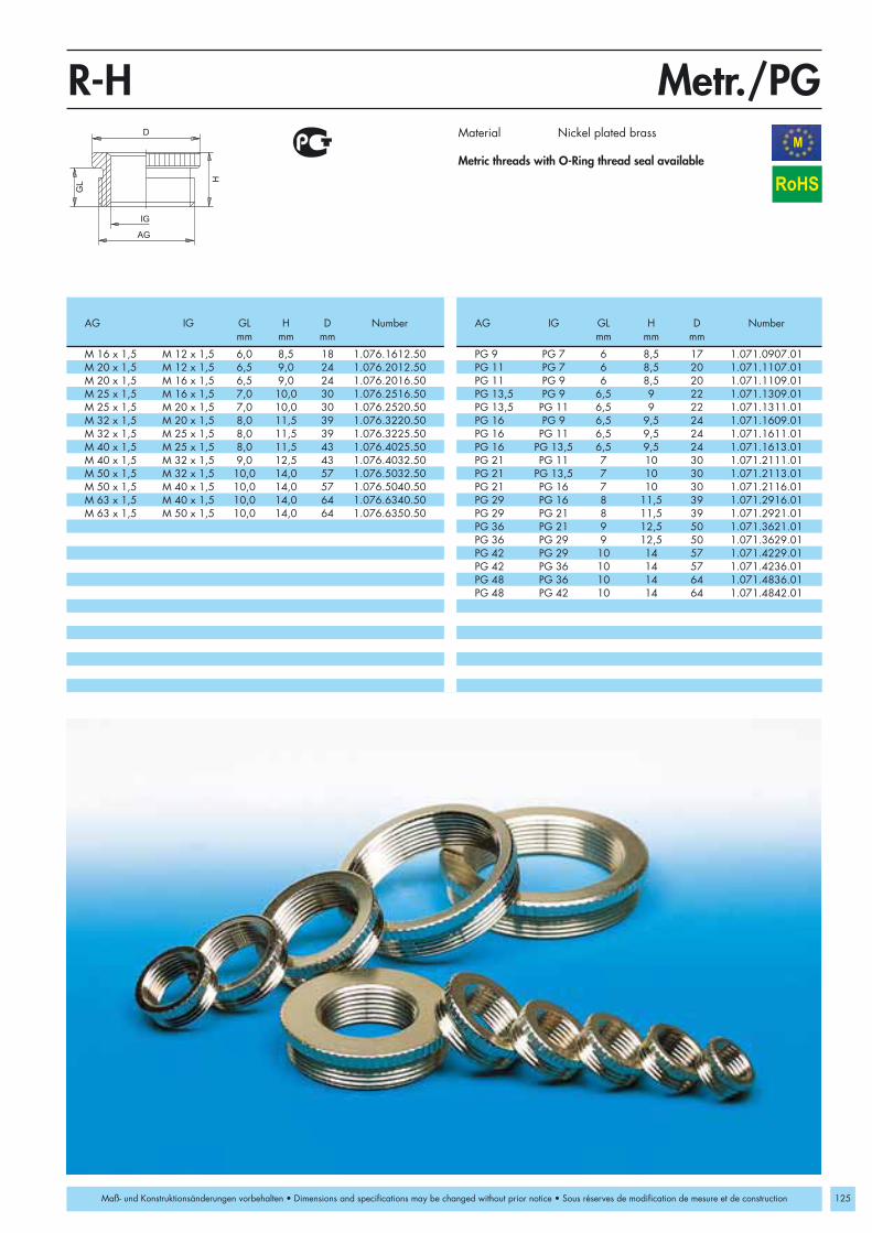
M 16 x 1,5 M 12 x 1,5 6,0 8,5 18 1.076.1612.50 PG 9 PG 7 6 8,5 17 1.071.0907.01M 20 x 1,5 M 12 x 1,5 6,5 9,0 24 1.076.2012.50 PG 11 PG 7 6 8,5 20 1.071.1107.01M 20 x 1,5 M 16 x 1,5 6,5 9,0 24 1.076.2016.50 PG 11 PG 9 6 8,5 20 1.071.1109.01M 25 x 1,5 M 16 x 1,5 7,0 10,0 30 1.076.2516.50 PG 13,5 PG 9 6,5 9 22 1.071.1309.01M 25 x 1,5 M 20 x 1,5 7,0 10,0 30 1.076.2520.50 PG 13,5 PG 11 6,5 9 22 1.071.1311.01M 32 x 1,5 M 20 x 1,5 8,0 11,5 39 1.076.3220.50 PG 16 PG 9 6,5 9,5 24 1.071.1609.01M 32 x 1,5 M 25 x 1,5 8,0 11,5 39 1.076.3225.50 PG 16 PG 11 6,5 9,5 24 1.071.1611.01M 40 x 1,5 M 25 x 1,5 8,0 11,5 43 1.076.4025.50 PG 16 PG 13,5 6,5 9,5 24 1.071.1613.01M 40 x 1,5 M 32 x 1,5 9,0 12,5 43 1.076.4032.50 PG 21 PG 11 7 10 30 1.071.2111.01M 50 x 1,5 M 32 x 1,5 10,0 14,0 57 1.076.5032.50 PG 21 PG 13,5 7 10 30 1.071.2113.01M 50 x 1,5 M 40 x 1,5 10,0 14,0 57 1.076.5040.50 PG 21 PG 16 7 10 30 1.071.2116.01M 63 x 1,5 M 40 x 1,5 10,0 14,0 64 1.076.6340.50 PG 29 PG 16 8 11,5 39 1.071.2916.01M 63 x 1,5 M 50 x 1,5 10,0 14,0 64 1.076.6350.50 PG 29 PG 21 8 11,5 39 1.071.2921.01
PG 36 PG 21 9 12,5 50 1.071.3621.01PG 36 PG 29 9 12,5 50 1.071.3629.01PG 42 PG 29 10 14 57 1.071.4229.01PG 42 PG 36 10 14 57 1.071.4236.01PG 48 PG 36 10 14 64 1.071.4836.01PG 48 PG 42 10 14 64 1.071.4842.01
H
GL
D
AG
IG
Metr./PGR-HM
125
RoHS
Maß- und Konstruktionsänderungen vorbehalten • Dimensions and specifications may be changed without prior notice • Sous réserves de modification de mesure et de construction
Material Nickel plated brass
Metric threads with O-Ring thread seal available
AG IG GL H D Number AG IG GL H D Numbermm mm mm mm mm mm
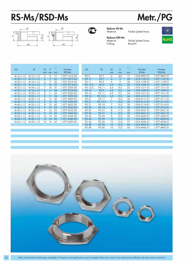
126
AG
IG
GLH
AG
IG
GLH
Metr./PGRS-Ms/RSD-MsM
M 16 x 1,5 M 12 x 1,5 5 8 17 1.077.1612.50 PG 9 PG 7 6 8,8 17 1.074.0907.01 1.077.0907.01M 20 x 1,5 M 12 x 1,5 6 9 22 1.077.2012.50 PG 11 PG 7 6 9 20 1.074.1107.01 1.077.1107.01M 20 x 1,5 M 16 x 1,5 6 9 22 1.077.2016.50 PG 11 PG 9 6 9 20 1.074.1109.01 1.077.1109.01M 25 x 1,5 M 16 x 1,5 7 10 27 1.077.2516.50 PG 13,5 PG 9 6,5 9,5 22 1.074.1309.01 1.077.1309.01M 25 x 1,5 M 20 x 1,5 7 10 27 1.077.2520.50 PG 13,5 PG 11 6,5 9,5 22 1.074.1311.01 1.077.1311.01M 32 x 1,5 M 16 x 1,5 8 11 34 1.077.3216.50 PG 16 PG 9 6,5 9,5 24 1.074.1609.01 1.077.1609.01M 32 x 1,5 M 20 x 1,5 8 11 34 1.077.3220.50 PG 16 PG 11 6,5 9,5 24 1.074.1611.01 1.077.1611.01M 32 x 1,5 M 25 x 1,5 8 11 34 1.077.3225.50 PG 16 PG 13,5 6,5 9,5 24 1.074.1613.01 1.077.1613.01M 40 x 1,5 M 20 x 1,5 8 12 43 1.077.4020.50 PG 21 PG 11 7 10,3 30 1.074.2111.01 1.077.2111.01M 40 x 1,5 M 25 x 1,5 8 12 43 1.077.4025.50 PG 21 PG 13,5 7 10,3 30 1.074.2113.01 1.077.2113.01M 40 x 1,5 M 32 x 1,5 8 12 43 1.077.4032.50 PG 21 PG 16 7 10,3 30 1.074.2116.01 1.077.2116.01M 50 x 1,5 M 25 x 1,5 9 13 55 1.077.5025.50 PG 29 PG 16 8 11,5 40 1.074.2916.01 1.077.2916.01M 50 x 1,5 M 32 x 1,5 9 13 55 1.077.5032.50 PG 29 PG 21 8 11,5 40 1.074.2921.01 1.077.2921.01M 50 x 1,5 M 40 x 1,5 9 13 55 1.077.5040.50 PG 36 PG 21 9 12,5 50 1.074.3621.01 1.077.3621.01M 63 x 1,5 M 32 x 1,5 10 14 65 1.077.6332.50 PG 36 PG 29 9 12,5 50 1.074.3629.01 1.077.3629.01M 63 x 1,5 M 40 x 1,5 10 14 65 1.077.6340.50 PG 42 PG 29 10 13,5 57 1.074.4229.01 1.077.4229.01M 63 x 1,5 M 50 x 1,5 10 14 65 1.077.6350.50 PG 42 PG 36 10 13,5 57 1.074.4236.01 1.077.4236.01
PG 48 PG 36 10 13,5 64 1.074.4836.01 1.077.4836.01PG 48 PG 42 10 13,5 64 1.074.4842.01 1.077.4842.01
RoHS
Maß- und Konstruktionsänderungen vorbehalten • Dimensions and specifications may be changed without prior notice • Sous réserves de modification de mesure et de construction
Reducer RS-MsMaterial Nickel plated brass
Reducer RSD-MsMaterial Nickel plated brassO-Ring Buna-N
AG IG GL H Number AG IG GL H Number Numbermm mm mm RSD-Ms mm mm mm RS-Ms RSD-Ms

Metr./PGRS-INOX/RSD-INOXM
127
M 16 x 1,5 M 12 x 1,5 5 9 17 1.094.1612.50 1.097.1612.50 PG 9 PG 7 6 8,8 17 1.094.0907.01 1.097.0907.01M 20 x 1,5 M 12 x 1,5 6 9,5 22 1.094.2012.50 1.097.2012.50 PG 11 PG 7 6 9 22 1.094.1107.01 1.097.1107.01M 20 x 1,5 M 16 x 1,5 6 9,5 22 1.094.2016.50 1.097.2016.50 PG 11 PG 9 6 9 22 1.094.1109.01 1.097.1109.01M 25 x 1,5 M 16 x 1,5 7 10,5 27 1.094.2516.50 1.097.2516.50 PG 13,5 PG 9 6,5 9,5 22 1.094.1309.01 1.097.1309.01M 25 x 1,5 M 20 x 1,5 7 10,5 27 1.094.2520.50 1.097.2520.50 PG 13,5 PG 11 6,5 9,5 22 1.094.1311.01 1.097.1311.01M 32 x 1,5 M 16 x 1,5 8 12,5 34 1.094.3216.50 1.097.3216.50 PG 16 PG 9 6,5 9,5 24 1.094.1609.01 1.097.1609.01M 32 x 1,5 M 20 x 1,5 8 12,5 34 1.094.3220.50 1.097.3220.50 PG 16 PG 11 6,5 9,5 24 1.094.1611.01 1.097.1611.01M 32 x 1,5 M 25 x 1,5 8 12,5 34 1.094.3225.50 1.097.3225.50 PG 16 PG 13,5 6,5 9,5 24 1.094.1613.01 1.097.1613.01M 40 x 1,5 M 20 x 1,5 8 13 43 1.094.4020.50 1.097.4020.50 PG 21 PG 11 7 10,3 30 1.094.2111.01 1.097.2111.01M 40 x 1,5 M 25 x 1,5 8 13 43 1.094.4025.50 1.097.4025.50 PG 21 PG 13,5 7 10,3 30 1.094.2113.01 1.097.2113.01M 40 x 1,5 M 32 x 1,5 8 13 43 1.094.4032.50 1.097.4032.50 PG 21 PG 16 7 10,3 30 1.094.2116.01 1.097.2116.01M 50 x 1,5 M 25 x 1,5 9 15 55 1.094.5025.50 1.097.5025.50 PG 29 PG 16 8 11,5 40 1.094.2916.01 1.097.2916.01M 50 x 1,5 M 32 x 1,5 9 15 55 1.094.5032.50 1.097.5032.50 PG 29 PG 21 8 11,5 40 1.094.2921.01 1.097.2921.01M 50 x 1,5 M 40 x 1,5 9 15 55 1.094.5040.50 1.097.5040.50 PG 36 PG 21 9 12,5 50 1.094.3621.01 1.097.3621.01M 63 x 1,5 M 32 x 1,5 10 16,5 65 1.094.6332.50 1.097.6332.50 PG 36 PG 29 9 12,5 50 1.094.3629.01 1.097.3629.01M 63 x 1,5 M 40 x 1,5 10 16,5 65 1.094.6340.50 1.097.6340.50 PG 42 PG 29 10 13,5 57 1.094.4229.01 1.097.4229.01M 63 x 1,5 M 50 x 1,5 10 16,5 65 1.094.6350.50 1.097.6350.50 PG 42 PG 36 10 13,5 57 1.094.4236.01 1.097.4236.01
PG 48 PG 36 10 13,5 64 1.094.4836.01 1.097.4836.01PG 48 PG 42 10 13,5 64 1.094.4842.01 1.097.4842.01
AG
IG
GLH
AG
IG
GLH
RoHS
Maß- und Konstruktionsänderungen vorbehalten • Dimensions and specifications may be changed without prior notice • Sous réserves de modification de mesure et de construction
RS-INOXMaterial INOX (1.4305)
RSD-INOXMaterial INOX (1.4305)O-Ring Buna-N
O-Ring made of FPM / VMQ on request
316 Stainless Steel available upon request
AG IG GL H Number Number AG IG GL H Number Numbermm mm mm RS-INOX RSD-INOX mm mm mm RS-INOX RSD-INOX
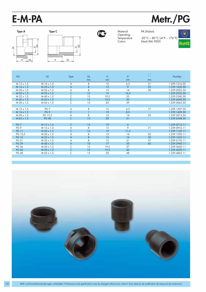
128
M 12 x 1,5 M 16 x 1,5 A 8 12 6,5 21 1.239.1216.50M 16 x 1,5 M 20 x 1,5 A 8 13 9 25 1.239.1620.50M 20 x 1,5 M 25 x 1,5 A 8 15 14 30 1.239.2025.50M 25 x 1,5 M 32 x 1,5 C 15 15 16,5 1.239.2532.50M 32 x 1,5 M 40 x 1,5 C 15 19,5 23 1.239.3240.50M 40 x 1,5 M 50 x 1,5 C 15 19,5 30 1.239.4050.50M 50 x 1,5 M 63 x 1,5 C 15 20 39 1.239.5063.50
M 12 x 1,5 PG 7 A 8 12 6,5 17 1.239.1207.50M 16 x 1,5 PG 9 C 1 19 8,5 1.239.1609.50M 20 x 1,5 PG 13,5 A 8 13 14 25 1.239.2013.50M 63 x 1,5 PG 48 C 15 20 51 1.239.6348.50
PG 7 M 12 x 1,5 C 15 19 6 1.239.0712.11PG 9 M 16 x 1,5 A 8 12 9 21 1.239.0916.11PG 11 M 20 x 1,5 C 15 19 11,5 1.239.1120.11PG 13,5 M 20 x 1,5 A 8 13 14 25 1.239.1320.11PG 16 M 25 x 1,5 A 8 15 16 30 1.239.1625.11PG 21 M 32 x 1,5 A 8 15 21 37 1.239.2132.11PG 29 M 40 x 1,5 A 10 17 30 45 1.239.2940.11PG 36 M 50 x 1,5 C 15 19,5 37 1.239.3650.11PG 42 M 50 x 1,5 C 15 19,5 43 1.239.4250.11PG 48 M 63 x 1,5 C 15 20 48 1.239.4863.11
Metr./PGE-M-PAM
IG
H GL
D AG
H GL
D AG
RoHS
Maß- und Konstruktionsänderungen vorbehalten • Dimensions and specifications may be changed without prior notice • Sous réserves de modification de mesure et de construction
Type A Type C Material PA (Nylon)OperatingTemperature -20 °C – 80 °C (-4 °F – 176 °F)Colors black RAL 9005
AG IG Type GL H D Numbermm mm mm mm

M 12 x 1,5 M 16 x 1,5 5 15 18 1.033.1216.50M 16 x 1,5 M 20 x 1,5 6 17,5 22 1.033.1620.50M 20 x 1,5 M 25 x 1,5 6,5 19 27 1.033.2025.50M 25 x 1,5 M 32 x 1,5 6,5 21 34 1.033.2532.50M 32 x 1,5 M 40 x 1,5 7 23 42 1.033.3240.50M 40 x 1,5 M 50 x 1,5 9 31 53 1.033.4050.50M 50 x 1,5 M 63 x 1,5 9 31 66 1.033.5063.50
PG 7 PG 9 5 15 17 1.033.0709.01PG 9 PG 11 6 16,5 20 1.033.0911.01PG 9 PG 13,5 6 17,5 22 1.033.0913.01PG 11 PG 13,5 6 17,5 22 1.033.1113.01PG 11 PG 16 6 18,5 24 1.033.1116.01PG 11 PG 21 6 20,5 30 1.033.1121.01PG 13,5 PG 16 6,5 19 24 1.033.1316.01PG 13,5 PG 21 6,5 21 30 1.033.1321.01PG 16 PG 21 6,5 21 30 1.033.1621.01PG 16 PG 29 6,5 22,5 39 1.033.1629.01PG 21 PG 29 7 23 39 1.033.2129.01PG 29 PG 36 8 27,5 50 1.033.2936.01PG 36 PG 42 9 31 57 1.033.3642.01PG 42 PG 48 10 33 64 1.033.4248.01PG 11 * PG 13,5 8 15 24 1.233.1113.11PG 13,5 * PG 16 9 16 27 1.233.1316.11PG 16 * PG 21 10 19 33 1.233.1621.11PG 21 * PG 29 11 21 42 1.233.2129.11
H
AG
GL
IG
D
Metr./PGE-Ms/E-KM
129
RoHS
Maß- und Konstruktionsänderungen vorbehalten • Dimensions and specifications may be changed without prior notice • Sous réserves de modification de mesure et de construction
Enlarger E-MsMaterial Nickel plated brass
Enlarger K-FsMaterial PA (Nylon)Colors black RAL 7035
* Type K-Fs
AG IG GL H D Numbermm mm mm

130
M 16 x 1,5 PG 9 6 10,5 20 1.039.1609.01M 20 x 1,5 PG 11 6,5 12,5 22 1.039.2011.01M 20 x 1,5 PG 13,5 6,5 12,5 22 1.039.2013.01M 20 x 1,5 PG 16 6,5 12,5 24 1.039.2016.01M 25 x 1,5 PG 16 6,5 12,5 28 1.039.2516.01M 25 x 1,5 PG 21 6,5 14,5 30 1.039.2521.01M 32 x 1,5 PG 29 7 16 39 1.039.3229.01
M 16 x 1,5 1/2“ NPT 6 17 24 1.171.1612.50M 20 x 1,5 1/2“ NPT 6 17 24 1.171.2012.50M 25 x 1,5 1/2“ NPT 7 8 30 1.171.2512.50M 25 x 1,5 3/4“ NPT 7 19 30 1.171.2534.50M 32 x 1,5 1“ NPT 8 25 40 1.171.3210.50M 32 x 1,5 1 1/4“ NPT 8 25 46 1.171.3254.50
PG 9 M 16 x 1,5 6 10,5 20 1.039.0916.01PG 11 M 20 x 1,5 6,5 12,5 22 1.039.1120.01PG 13,5 M 20 x 1,5 6,5 12,5 22 1.039.1320.01PG 16 M 25 x 1,5 6,5 14,5 27 1.039.1625.01
PG 11 1/2” NPT 6 16,7 24 1.171.1112.01PG 13,5 1/2” NPT 6,5 17 24 1.171.1312.01PG 16 1/2” NPT 6,5 16,5 24 1.171.1612.01PG 21 1/2” NPT 7 8 30 1.171.2112.01PG 21 3/4” NPT 7 17 30 1.171.2134.01PG 29 1” NPT 8 12 40 1.171.2910.01
IG AGD
GLH
AG
IG
H GL
Metr./PG/NPTRE-MsM
RoHS
Maß- und Konstruktionsänderungen vorbehalten • Dimensions and specifications may be changed without prior notice • Sous réserves de modification de mesure et de construction
Material Nickel plated brass
AG IG GL H D Numbermm mm mm mm

12 17 5 1.250.1201.5016 20 5 1.250.1601.5020 25 5 1.250.2001.5025 30 5 1.250.2501.5032 37 5 1.250.3201.5040 45 5 1.250.4001.5050 56 5 1.250.5001.5063 70 5 1.250.6301.50
16 9 19,8 15 1.282.1600.5020 12 24 19 1.282.2000.5025 12 29,5 24 1.282.2500.5032 14 37,5 30 1.282.3200.5040 14 65,8 37 1.282.4000.5050 18 55,8 46 1.282.5000.5063 20 68,8 56 1.282.6300.50
D
H
AGG
L
Ø
SW
Metr.DS/WNM
131
RoHS
Maß- und Konstruktionsänderungen vorbehalten • Dimensions and specifications may be changed without prior notice • Sous réserves de modification de mesure et de construction
Seal Plug DSMaterial ElastomerProtection IP 54 OperatingTemperature -20 °C – 80 °C (-4 °F – 176 °F)
Threaded Seal Hex Plug WNMaterial PE (Nylon)Protection IP 54OperatingTemperature -20 °C – 80 °C (-4 °F – 176 °F)
Ø D H Numbermm mm mm
AG GL Ø Numbermm mm mm
Seal Plug DS Threaded Seal Hex Plug WN
Seal Plug DS Threaded Seal Hex Plug WN

132
M 12 x 1,5 10 1,5 1.321.1200.57 1.321.1200.58M 16 x 1,5 12 1,5 1.321.1600.57 1.321.1600.58M 20 x 1,5 17 1,8 1.321.2000.57 1.321.2000.58M 25 x 1,5 22 2 1.321.2500.57 1.321.2500.58M 32 x 1,5 29 2 1.321.3200.57 1.321.3200.58M 40 x 1,5 35 2 1.321.4000.57 1.321.4000.58M 50 x 1,5 43 2 1.321.5000.57 1.321.5000.58M 63 x 1,5 55 2 1.321.6300.57 1.321.6300.58
PG 7 10 1,5 1.321.0700.17 1.321.0700.21PG 9 12 1,5 1.321.0900.17 1.321.0900.21PG 11 16 1,5 1.321.1100.17 1.321.1100.21PG 13,5 17 1,8 1.321.1300.17 1.321.1300.21PG 16 18 1,5 1.321.1600.17 1.321.1600.21PG 21 26 2 1.321.2100.17 1.321.2100.21PG 29 33 2 1.321.2900.17 1.321.2900.21PG 36 43 2 1.321.3600.17 1.321.3600.21PG 42 50 2 1.321.4200.17 1.321.4200.21PG 48 55 2 1.321.4800.17 1.321.4800.21
3/8” NPT 13 2 1.321.3800.77 1.321.3800.781/2” NPT 19 1,8 1.321.1200.77 1.321.1200.783/4“ NPT 22 2 1.321.3400.77 1.321.3400.781” NPT 29 2 1.321.1000.77 1.321.1000.781 1/4“ NPT 38 2,5 1.321.5400.77 1.321.5400.781 1/2“ NPT 45 2,5 1.321.6400.77 1.321.6400.78
S
d
Metr./PGM
RoHS
Maß- und Konstruktionsänderungen vorbehalten • Dimensions and specifications may be changed without prior notice • Sous réserves de modification de mesure et de construction
O-Ring NBRMaterial Buna-NOperatingTemperature -30 °C – 120 °C (-22 °F – 248 °F)
O-Ring FPMMaterial FPMOperatingTemperature -40 °C – 200 °C (-104 °F – 392 °F)
Fits the Following Sizes d s Number Numbermm mm Buna-N FPM
O-Ring for HSK-K
O-Ring

M 12 x 1,5 12 16 2 1.325.1200.59 1.325.1200.50M 16 x 1,5 16 20 2 1.325.1600.59 1.325.1600.50M 20 x 1,5 20 25 2 1.325.2000.59 1.325.2000.50M 25 x 1,5 25 31 2 1.325.2500.59 1.325.2500.50M 32 x 1,5 32 38 2 1.325.3200.59 1.325.3200.50M 40 x 1,5 40 48 2 1.325.4000.59 1.325.4000.50M 50 x 1,5 50 58 2 1.325.5000.59 1.325.5000.50M 63 x 1,5 63 72 2 1.325.6300.59 1.325.6300.50
PG 7 12,5 16,5 1,5 1.325.0700.19 1.325.0700.20PG 9 15,2 19 1,5 1.325.0900.19 1.325.0900.20PG 11 18,6 22,5 1,5 1.325.1100.19 1.325.1100.20PG 13,5 20,4 25 1,5 1.325.1300.19 1.325.1300.20PG 16 22,5 27 1,5 1.325.1600.19 1.325.1600.20PG 21 28,3 33,5 1,5 1.325.2100.19 1.325.2100.20PG 29 37 43,5 2 1.325.2900.19 1.325.2900.20PG 36 47 55 2 1.325.3600.19 1.325.3600.20PG 42 54 63 2 1.325.4200.19 1.325.4200.20PG 48 59,3 69 2 1.325.4800.19 1.325.4800.20
D
S
d
Metr./PGM
133
RoHS
Maß- und Konstruktionsänderungen vorbehalten • Dimensions and specifications may be changed without prior notice • Sous réserves de modification de mesure et de construction
Thread Seal Ring PEMaterial PolyethylenOperatingTemperature -30 °C – 70 °C (-22 °F – 158 °F)
Thread Seal Ring HDMaterial Fiber-reinforced plasticOperatingTemperature -55 °C – 300 °C (-67 °F – 572 °F)
Size d D S Number Numbermm mm mm PE HD
Thread Seal Rings

134
M12x1,5 5,5 15,0 16 5 - 7,5 1.143.1200.50M16x1,5 6,0 16,0 19 7 - 10 1.143.1600.50M20x1,5 6,5 18,0 24 10 - 14 1.143.2000.50M25x1,5 8,0 21,0 34 12 - 21,5 1.143.2500.50M32x1,5 8,0 22,0 42 16 - 27 1.143.3200.50M40x1,5 9,5 25,5 52 22 - 33 1.143.4000.50M50x1,5 9,5 25,5 52 25 - 38,5 1.143.5000.50
PG 7 5,5 14,8 16 5,5 - 8 1.143.0700.01PG 9 6 16,6 19 6,5 - 10 1.143.0900.01PG 11 6 17,3 22 7,5 - 12 1.143.1100.01PG 13,5 6,5 17,8 24 8,5 - 14 1.143.1300.01PG 16 6,5 18,3 26 9,5 - 16 1.143.1600.01PG 21 7,5 20,8 33 12 - 21 1.143.2100.01PG 29 8 21,8 42 19 - 30 1.143.2900.01PG 36 9,5 25,3 52 25 - 37 1.143.3600.01PG 42 10 26,3 59 31 - 43 1.143.4200.01PG 48 11 27,3 64 35 - 48 1.143.4800.01
AG
GL
H
Metr./PGKLERoHS
Maß- und Konstruktionsänderungen vorbehalten • Dimensions and specifications may be changed without prior notice • Sous réserves de modification de mesure et de construction
Material Nickel plated brass
AG GL H Numbermm mm mm mm

M 16x1,5 M16x1,5 8 23 28,5 5 19 1.316.1600.50 1.316.1601.50M 20x1,5 M 20x1,5 9 30,5 35 7 24 1.316.2000.50 1.316.2001.50M 25x1,5 M 25x1,5 11 40 49 10 33 1.316.2500.50 1.316.2501.50
Pg 9 M 16x1,5 8 23 28,5 5 19 1.316.0900.11 1.316.0901.11Pg 13,5 M 20x1,5 9 30,5 35 7 24 1.316.1300.11 1.316.1301.11Pg 21 M 25x1,5 11 40 49 10 33 1.316.2100.11 1.316.2101.11
M 16 x 1,5 PG 9 8 23 28,5 5 19 1.315.1600.50 1.315.1601.50M 20 x 1,5 PG 13,5 9 30,5 35 7 24 1.315.2000.50 1.315.2001.50M 25 x 1,5 PG 21 11 40 49 10 33 1.315.2500.50 1.315.2501.50M 32 x 1,5 PG 29 11 51,5 60 14 42 1.315.3200.50 1.315.3201.50
PG 9 PG 9 8 23 28,5 5 19 1.315.0900.11 1.315.0901.11PG 11 PG 11 8 27 31,5 6 22 1.315.1100.11 1.315.1101.11PG 13,5 PG 13,5 9 30,5 35 7 24 1.315.1300.11 1.315.1301.11PG 16 PG 16 10 32,5 37,5 8 27 1.315.1600.11 1.315.1601.11PG 21 PG 21 11 40 49 10 33 1.315.2100.11 1.315.2101.11PG 29 PG 29 11 51,5 60 14 42 1.315.2900.11 1.315.2901.11
3/8” NPT PG 9 15 23 28,5 5 19 1.315.3800.70 1.315.3801.701/2” NPT PG 13,5 13 30,5 35 7 24 1.315.1200.70 1.315.1201.703/4” NPT PG 21 13 40 49 10 33 1.315.3400.70 1.315.3401.701” NPT PG 29 19 51,5 60 14 42 1.315.1000.70 1.315.1001.70
GL
H
AG
L
IG
Metr./PG/NPTM
135
RoHS
Maß- und Konstruktionsänderungen vorbehalten • Dimensions and specifications may be changed without prior notice • Sous réserves de modification de mesure et de construction
Material PA (Nylon)O-Ring Buna-NProtection IP 68OperatingTemperature -20 °C – 80 °C (-4 °F – 176 °F)Colors grey RAL 7035
black RAL 9005
AG IG GL H L Number Numbermm mm mm mm grey black
90° Snap Elbow

136
M 16 x 1,5 4 49 47 37 15 29,5 1.312.1600.50 1.312.1601.50M 20 x 1,5 4 49 47 37 15 29,5 35 1.312.2000.50 1.312.2001.50M 25 x 1,5 6 69 65 52 21 42 44 1.312.2500.50 1.312.2501.50M 32 x 1,5 6 90 78 65 9 65 55 1.312.3200.50 1.312.3201.50M 40 x 1,5 6 100 94 80 10 80 66 1.312.4000.50 1.312.4001.50M 50 x 1,5 6 116 101 88 12 88,5 76 1.312.5000.50 1.312.5001.50
PG 11 4 49 47 37 15 29,5 35 1.312.1100.11 1.312.1101.11PG 16 4 49 47 37 15 29,5 35 1.312.1600.11 1.312.1601.11PG 21 6 69 65 52 21 42 44 1.312.2100.11 1.312.2101.11PG 29 6 90 78 65 9 65 55 1.312.2900.11 1.312.2901.11PG 36 6 100 94 80 10 80 66 1.312.3600.11 1.312.3601.11PG 48 6 116 101 88 12 88,5 76 1.312.4800.11 1.312.4801.11
Ø mm
DE
C
B
A F
C
B
A
H
Metr./PGKF-GM
RoHS
Maß- und Konstruktionsänderungen vorbehalten • Dimensions and specifications may be changed without prior notice • Sous réserves de modification de mesure et de construction
Material PA (Nylon)Seal Buna-NProtection IP 65OperatingTemperature -20 °C – 80 °C (-4 °F – 176 °F)Colors grey RAL 7011
black RAL 9005
Size Ø A B C D F H Number Numbermm mm mm mm mm mm mm grey black

G
C
E
D
H
A
Metr./PGFW-ZN/TM
M 20 x 1,5 56 53 44 5,5 35 1.306.2000.50M 25 x 1,5 65 63 54 5,5 42 1.306.2500.50M 32 x 1,5 75 71 60 5,5 52 1.306.3200.50M 50 x 1,5 93 89 72 6,5 69 1.306.5000.50M 63 x 1,5 114 96 84 6,5 74 1.306.6300.50
PG 9 50 45 37 4,3 30 1.306.0900.05PG 11 50 45 37 4,3 30 1.306.1100.05PG 13,5 56 53 44 5,5 35 1.306.1300.05PG 16 56 53 44 5,5 35 1.306.1600.05PG 21 65 63 54 5,5 42 1.306.2100.05PG 29 74 70 60 5,5 52 1.306.2900.05PG 36 94 89 72 6,5 69 1.306.3600.05PG 42 114 96 84 6,5 74 1.306.4200.05PG 48 114 96 84 6,5 74 1.306.4800.05
PG 9 50 45 37 4,3 29 1.306.0900.14PG 11 50 45 37 4,3 29 1.306.1100.14PG 13,5 56 53 44 5,5 35 1.306.1300.14PG 16 56 53 44 5,5 35 1.306.1600.14PG 21 68 68 55,5 5,5 43 1.306.2100.14PG 29 74 70 60 5,5 52 1.306.2900.14PG 36 93 88 72 6,5 68 1.306.3600.14
137
RoHS
Maß- und Konstruktionsänderungen vorbehalten • Dimensions and specifications may be changed without prior notice • Sous réserves de modification de mesure et de construction
Flange elbow ZN
Flange elbow T
Flange elbow ZNMaterial Zinc die castingProtection IP 65
Flange elbow TMaterial PA (Nylon)Protection IP 65Colors grey RAL 7035
Metric threads available upon request
A C D E G H Numbermm mm mm mm mm

138
75 2,2 6,0 1.480.5201.00 1.480.5201.11 120 7,8 54,0 1.480.5221.00 1.480.5221.11180 7,8 54,0 1.480.5223.00 1.480.5223.11
98 2,5 8,1 1.480.5203.00 1.480.5203.11 240 7,8 54,0 1.480.5225.00 1.480.5225.11300 7,8 54,0 1.480.5226.00 1.480.5226.11
130 2,9 8,3 1.480.5205.00 1.480.5205.11 370 7,8 54,0 1.480.5227.00 1.480.5227.11290 2,9 8,3 1.480.5207.00 1.480.5207.11 450 7,8 54,0 1.480.5229.00 1.480.5229.11
540 7,8 54,0 1.480.5231.00 1.480.5231.11140 3,6 13,0 1.480.5209.00 1.480.5209.11 730 7,8 54,0 1.480.5233.00 1.480.5233.11200 3,6 13,0 1.480.5210.00 1.480.5210.11
780 9,0 77,0 1.480.5234.00 1.480.5234.11160 4,5 18,3 1.480.5211.00 1.480.5211.11
225 12,0 110,0 1.480.5235.00 1.480.5235.11178 4,8 22,0 1.480.5213.00 1.480.5213.11 500 12,0 110,0 1.480.5237.00 1.480.5237.11200 4,8 22,0 1.480.5215.00 1.480.5215.11 720 12,0 110,0 1.480.5239.00 1.480.5239.11250 4,8 22,0 1.480.5216.00 1.480.5216.11 850 12,0 110,0 1.480.5241.00 1.480.5241.11290 4,8 22,0 1.480.5217.00 1.480.5217.11 1000 12,0 110,0 1.480.5243.00 1.480.5243.11360 4,8 22,0 1.480.5219.00 1.480.5219.11
19 19 1.480.1919.00 1.480.1919.1127 27 1.480.2727.00 1.480.2727.11
L
B
L
B
ST/HDRoHS
Maß- und Konstruktionsänderungen vorbehalten • Dimensions and specifications may be changed without prior notice • Sous réserves de modification de mesure et de construction
Base SN SB
STN STB HDN HDBL B -60 °C – 110 °C -60 °C – 110 °C L B -60 °C – 110 °C -60 °C – 110 °Cmm mm (-76 °F – 230 °F) (-76 °F – 230 °F) mm mm (-76 °F – 230 °F) (-76 °F – 230 °F)
Cable TiesCable Ties STN/STB Material: PA (Nylon)
Colors: natural, other colors upon request (STN),
black (UV resistant) (STB)
Base SN/SB Colors: natural (SN)black (UV resistant) (SB)
Cable Ties HDN/HDB Material: PA (Nylon) Colors: natural, other colors upon request (HDN),
black (UV resistant) (HDB)Cable Ties STN/STB Cable Ties HDN/HDB
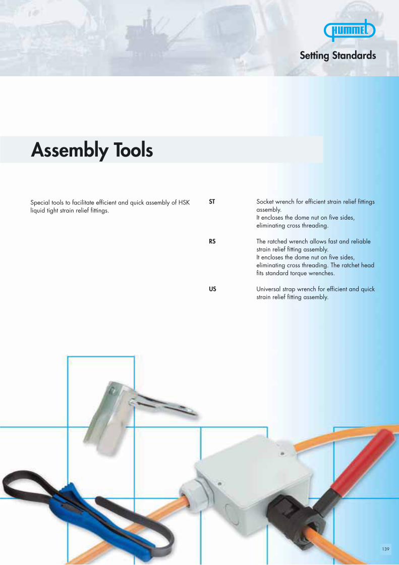
139
Setting Standards
Special tools to facilitate efficient and quick assembly of HSKliquid tight strain relief fittings.
Assembly Tools
ST Socket wrench for efficient strain relief fittingsassembly. It encloses the dome nut on five sides, eliminating cross threading.
RS The ratched wrench allows fast and reliablestrain relief fitting assembly.It encloses the dome nut on five sides, eliminating cross threading. The ratchet headfits standard torque wrenches.
US Universal strap wrench for efficient and quickstrain relief fitting assembly.

140
LDC
ST
14 60 9 19 1.500.1400.0415 60 9,5 20 1.500.1500.0417 60 10 23,5 1.500.1700.0419 60 11 26 1.500.1900.0420 60 12 27 1.500.2000.0422 60 13 29,5 1.500.2200.0424 60 15 32,5 1.500.2400.0427 60 17 35,5 1.500.2700.0430 60 18 40,5 1.500.3000.0433 60 20 43,5 1.500.3300.0436 60 22 47,5 1.500.3600.0440 100 25 52,5 1.500.4000.0441 100 27 53,5 1.500.4100.0442 100 27 54,5 1.500.4200.0446 100 31 60 1.500.4600.0450 100 32 65,5 1.500.5000.0453 100 32 71,5 1.500.5300.0455 100 32 72 1.500.5500.0457 100 36 75,5 1.500.5700.0460 100 38 78,5 1.500.6000.0464 100 40 84 1.500.6400.0465 100 42 85 1.500.6500.0468 100 42 87 1.500.6800.04
Maß- und Konstruktionsänderungen vorbehalten • Dimensions and specifications may be changed without prior notice • Sous réserves de modification de mesure et de construction
Tool for efficient and safe assembly of the HSK strain relief fittings
L C D Numbermm mm mm mm
Socket wrench
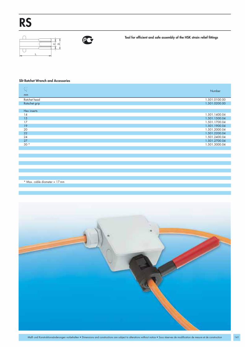
141
L
DC
RS
1.501.0100.001.501.0200.00
14 1.501.1400.0415 1.501.1500.0417 1.501.1700.0419 1.501.1900.0420 1.501.2000.0422 1.501.2200.0424 1.501.2400.0427 1.501.2700.0430 * 1.501.3000.04
Maß- und Konstruktionsänderungen vorbehalten • Dimensions and constructions are subject to alterations without notice • Sous réserves de modification de mesure et de construction
Slit Ratchet Wrench and Accessories
Ratchet headRatschet grip
Hex inserts
* Max. cable diameter = 17mm
Tool for efficient and safe assembly of the HSK strain relief fittings
Numbermm

142
L
DC
14 – 33 1.503.0100.00
US
Maß- und Konstruktionsänderungen vorbehalten • Dimensions and constructions are subject to alterations without notice • Sous réserves de modification de mesure et de construction
Universal strap wrench for efficient and quick strain relief fitting assembly.
Numbermm
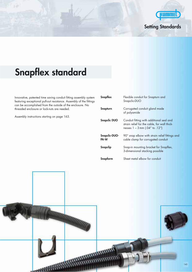
143
Innovative, patented time saving conduit fitting assembly systemfeaturing exceptional pull-out resistance. Assembly of the fittingscan be accomplished from the outside of the enclosure. Nothreaded enclosure or lock-nuts are needed.
Assembly instructions starting on page 163.
Setting Standards
Snapflex standard
Snapflex Flexible conduit for Snapturn and Snapclic-DUO
Snapturn Corrugated conduit gland made of polyamide
Snapclic DUO Conduit fitting with additional seal and strain relief for the cable, for wall thick-nesses 1 – 3mm (.04“ to .12“)
Snapclic-DUO- 90° snap elbow with strain relief fittings andPA-W cable clamp for corrugated conduit
Snapclip Snap-in mounting bracket for Snapflex, 3-dimensional stacking possible
Snapform Sheet metal elbow for conduit

144
Dd
SnapflexM
16 10,7 16 1.510.1600.50 1.510.1601.5020 14,1 20 1.510.2000.50 1.510.2001.5025 18,3 25 1.510.2500.50 1.510.2501.5032 24,3 32 1.510.3200.50 1.510.3201.5040 31,2 40 1.510.4000.50 1.510.4001.5050 39,6 50 1.510.5000.50 1.510.5001.5063 50,6 63 1.510.6300.50 1.510.6301.50
RoHS
Maß- und Konstruktionsänderungen vorbehalten • Dimensions and specifications may be changed without prior notice • Sous réserves de modification de mesure et de construction
Material PA (Nylon)Operating -30 °C – 100 °C Temperature (-22 °F – 212 °F)Colors grey RAL 7031
black RAL 9005
PP upon request
Size d D Number NumberD mm mm grey black

145
AG
HGL
M
16 26,5 M16x1,5 16 1.515.1601.5020 29 M20x1,5 20 1.515.2001.5025 32 M25x1,5 25 1.515.2501.5032 36 M32x1,5 32 1.515.3201.5040 36 M40x1,5 40 1.515.4001.5050 40 M50x1,5 50 1.515.5001.50
RoHS
Maß- und Konstruktionsänderungen vorbehalten • Dimensions and specifications may be changed without prior notice • Sous réserves de modification de mesure et de construction
Assembly instructionssee page 169
Material PA (Nylon)Operating -20 °C – 80 °CTemperature (-4 °F – 176 °F)Colors black
International approval pending
Panel HoleSize H Ø Fits Snapflex NumberD mm mm Conduit
Snapturn

146
M 16 x 1,5 8 42 25 22 5 - 10 16 1.542.1601.50 5 - 10 DN 10 1.542.1610.50M 16 x 1,5 8 42 25 22 3 - 7 16 1.542.1601.51 3 - 7 DN 10 1.542.1610.51M 20 x 1,5 9 44 25 24 6 - 12 DN 12 1.542.2012.50M 20 x 1,5 9 44 25 24 5 - 9 DN 12 1.542.2012.51M 20 x 1,5 10 46 30 27 10 - 14 20 1.542.2001.50 10 - 14 DN 14 1.542.2014.50M 20 x 1,5 10 46 30 27 7 - 12 20 1.542.2001.51 7 - 12 DN 14 1.542.2014.51M 25 x 1,5 11 50 35 33 13 - 18 25 1.542.2501.50 13 - 16 DN 17 1.542.2517.50M 25 x 1,5 11 50 35 33 9 - 16 25 1.542.2501.51 9 - 16 DN 17 1.542.2517.51M 32 x 1,5 11 60 42 42 18 - 24 32 1.542.3201.50 18 - 22 DN 23 1.542.3223.50M 32 x 1,5 11 60 42 42 13 - 20 32 1.542.3201.51 13 - 20 DN 23 1.542.3223.51M 40 x 1,5 13 60 50 53 22 - 31 40 1.542.4001.50 22 - 28 DN 29 1.542.4029.50M 40 x 1,5 13 60 50 53 20 - 26 40 1.542.4001.51 20 - 26 DN 29 1.542.4029.51
PG 11 8 42 25 22 5 - 10 16 1.543.1116.14 5 - 10 DN 10 1.543.1110.14PG 11 8 42 25 22 3 - 7 16 1.543.1116.15 3 - 7 DN 10 1.543.1110.15PG 13,5 9 44 25 24 6 - 12 DN 12 1.543.1312.14PG 13,5 9 44 25 24 5 - 9 DN 12 1.543.1312.15PG 16 10 46 30 27 10 - 14 20 1.543.1620.14 10 - 14 DN 14 1.543.1614.14PG 16 10 46 30 27 7 - 12 20 1.543.1620.15 7 - 12 DN 14 1.543.1614.15PG 21 11 50 35 33 13 - 16 25 1.543.2125.14 13 - 16 DN 17 1.543.2117.14PG 21 11 50 35 33 9 - 16 25 1.543.2125.15 9 - 16 DN 17 1.543.2117.15PG 29 11 60 42 42 18 - 22 32 1.543.2932.14 18 - 22 DN 23 1.543.2923.14PG 29 11 60 42 42 13 - 20 32 1.543.2932.15 13 - 20 DN 23 1.543.2923.15PG 36 13 60 50 53 22 - 28 40 1.543.3640.14 22 - 28 DN 29 1.543.3629.14PG 36 13 60 50 53 20 - 16 40 1.543.3640.15 20 - 26 DN 29 1.543.3629.15
H
D AG
Metr./PGSnapclic-DUO-PAM
RoHS
Maß- und Konstruktionsänderungen vorbehalten • Dimensions and specifications may be changed without prior notice • Sous réserves de modification de mesure et de construction
Material PA (Nylon)Seal Buna-NOperating -40 °C – 100 °C Temperature (-40 °F – 212 °F)
NPT threads and elongated threads available upon request
AG GL H D Fits Snapflex Number Fits SM-WS Numbermm mm mm mm mm Conduit mm Conduit

M 16 x 1,5 6 38,5 23 20 5 - 10 16 1.547.1601.50 5 - 10 10 1.547.1610.50M 16 x 1,5 6 38,5 23 20 3 - 7 16 1.547.1601.51 3 - 7 10 1.547.1610.51M 20 x 1,5 6 39,5 25 22 6 - 12 12 1.547.2012.50M 20 x 1,5 6 39,5 25 22 5 - 9 12 1.547.2012.51M 20 x 1,5 6 41,5 29 24 10 - 14 20 1.547.2001.50 10 - 14 14 1.547.2014.50M 20 x 1,5 6 41,5 29 24 7 - 12 20 1.547.2001.51 7 - 12 14 1.547.2014.51M 25 x 1,5 7 44,5 30 30 13 - 18 25 1.547.2501.50 13 - 16 17 1.547.2517.50M 25 x 1,5 7 44,5 30 30 9 - 16 25 1.547.2501.51 9 - 16 17 1.547.2517.51M 32 x 1,5 8 52,5 39 40 18 - 24 32 1.547.3201.50 18 - 22 23 1.547.3223.50M 32 x 1,5 8 52,5 39 40 13 - 20 32 1.547.3201.51 13 - 20 23 1.547.3223.51M 40 x 1,5 8 59 45 50 22 - 31 40 1.547.4001.50 22 - 28 29 1.547.4029.50M 40 x 1,5 8 59 45 50 20 - 26 40 1.547.4001.51 20 - 26 29 1.547.4029.51
PG 11 6 38,5 23 20 5 - 10 16 1.548.1116.01 5 - 10 10 1.548.1110.01PG 11 6 38,5 23 20 3 - 7 16 1.548.1116.15 3 - 7 10 1.548.1110.15PG 13,5 6 39,5 25 22 6 - 12 12 1.548.1312.01PG 13,5 6 39,5 25 22 5 - 9 12 1.548.1312.15PG 16 6 41,5 29 24 10 - 14 20 1.548.1620.01 10 - 14 14 1.548.1614.01PG 16 6 41,5 29 24 7 - 12 20 1.548.1620.15 7 - 12 14 1.548.1614.15PG 21 7 44,5 30 30 13 - 16 25 1.548.2125.01 13 - 16 17 1.548.2117.01PG 21 7 44,5 30 30 9 - 16 25 1.548.2125.15 9 - 16 17 1.548.2117.15PG 29 8 52,5 39 40 18 - 22 32 1.548.2932.01 18 - 22 23 1.548.2923.01PG 29 8 52,5 39 40 13 - 20 32 1.548.2932.15 13 - 20 23 1.548.2923.15PG 36 8 59 45 50 22 - 28 40 1.548.3640.01 22 - 28 29 1.548.3629.01PG 36 8 59 45 50 20 - 16 40 1.548.3640.15 20 - 26 29 1.548.3629.15
D AG
Metr./PGSnapclic-DUO-MsM
147
RoHS
Maß- und Konstruktionsänderungen vorbehalten • Dimensions and specifications may be changed without prior notice • Sous réserves de modification de mesure et de construction
Material Nickel plated brass Clamping insert PA (Nylon)Seal Buna-NOperatingTemperature -40 °C – 100 °C (-40 °F – 212 °F)
NPT threads and elongated threads available upon requestEMI-version available
AG GL H D Fits Snapflex Number Fits SM-WS Numbermm mm mm mm mm Conduit mm Conduit

148
M 20 x 1,5 9 30,5 38 7 7 24 DN 10 1.552.2010.50M 25 x 1,5 11 40 53 10 10 33 20 1.552.2520.50 DN 14 1.552.2514.50M 25 x 1,5 11 40 53 10 10 33 25 1.552.2525.50 DN 17 1.552.2517.50M 32 x 1,5 11 51,5 64,5 14 14 42 32 1.552.3200.50 DN 23 1.552.3223.50
PG 13,5 9 30,5 38 25 7 24 DN 10 1.552.1310.14PG 16 10 32,5 41,5 30 8 27 16 1.552.1616.14 DN 12 1.552.1612.14PG 21 11 40 53 35 10 33 20 1.552.2120.14 DN 14 1.552.2114.14PG 21 11 40 53,5 35 10 33 25 1.552.2125.14 DN 17 1.552.2117.14PG 29 11 51,5 64,5 42 14 42 32 1.552.2932.14 DN 23 1.552.2923.14
1/2“ NPT 13 30,5 38 25 7 24 DN 10 1.552.1210.703/4“ NPT 13 40 53 35 10 33 20 1.552.3420.70 DN 14 1.552.3414.703/4“ NPT 13 40 53,5 35 10 33 25 1.552.3425.70 DN 17 1.552.3417.701“ NPT 19 51,5 64,5 42 14 42 32 1.552.1032.70 DN 23 1.552.1023.70
H
L
GL
AG
Metr./PG/NPTM
Snapclic-PA-W
RoHS
Maß- und Konstruktionsänderungen vorbehalten • Dimensions and constructions are subject to alterations without notice • Sous réserves de modification de mesure et de construction
Material PA (Nylon)O-Ring Buna-NOperating -20 °C – 80 °CTemperature (-4 °F – 176 °F)Colors black
AG GL H L R Fits Snapflex Number Fits SM-WS Numbermm mm mm mm mm Conduit Conduit
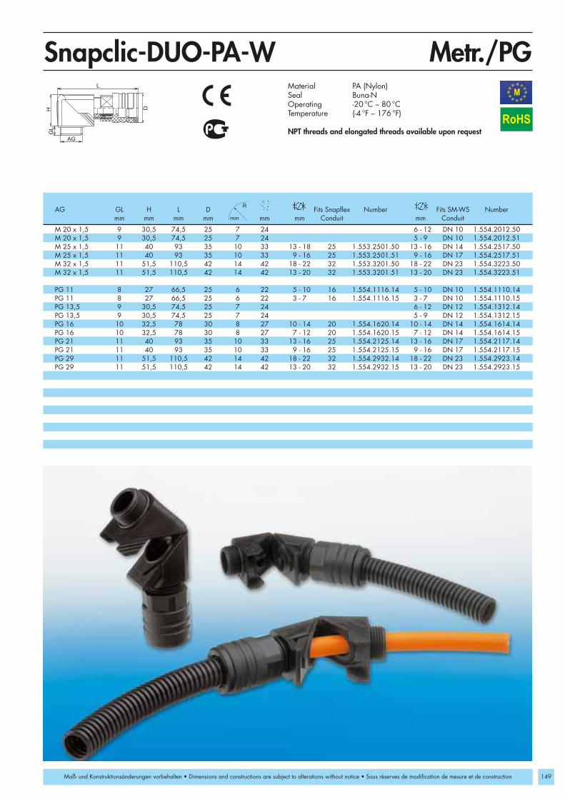
149
M 20 x 1,5 9 30,5 74,5 25 7 24 6 - 12 DN 10 1.554.2012.50M 20 x 1,5 9 30,5 74,5 25 7 24 5 - 9 DN 10 1.554.2012.51M 25 x 1,5 11 40 93 35 10 33 13 - 18 25 1.553.2501.50 13 - 16 DN 14 1.554.2517.50M 25 x 1,5 11 40 93 35 10 33 9 - 16 25 1.553.2501.51 9 - 16 DN 17 1.554.2517.51M 32 x 1,5 11 51,5 110,5 42 14 42 18 - 22 32 1.553.3201.50 18 - 22 DN 23 1.554.3223.50M 32 x 1,5 11 51,5 110,5 42 14 42 13 - 20 32 1.553.3201.51 13 - 20 DN 23 1.554.3223.51
PG 11 8 27 66,5 25 6 22 5 - 10 16 1.554.1116.14 5 - 10 DN 10 1.554.1110.14PG 11 8 27 66,5 25 6 22 3 - 7 16 1.554.1116.15 3 - 7 DN 10 1.554.1110.15PG 13,5 9 30,5 74,5 25 7 24 6 - 12 DN 12 1.554.1312.14PG 13,5 9 30,5 74,5 25 7 24 5 - 9 DN 12 1.554.1312.15PG 16 10 32,5 78 30 8 27 10 - 14 20 1.554.1620.14 10 - 14 DN 14 1.554.1614.14PG 16 10 32,5 78 30 8 27 7 - 12 20 1.554.1620.15 7 - 12 DN 14 1.554.1614.15PG 21 11 40 93 35 10 33 13 - 16 25 1.554.2125.14 13 - 16 DN 17 1.554.2117.14PG 21 11 40 93 35 10 33 9 - 16 25 1.554.2125.15 9 - 16 DN 17 1.554.2117.15PG 29 11 51,5 110,5 42 14 42 18 - 22 32 1.554.2932.14 18 - 22 DN 23 1.554.2923.14PG 29 11 51,5 110,5 42 14 42 13 - 20 32 1.554.2932.15 13 - 20 DN 23 1.554.2923.15
HGL
AG
L
D
Metr./PGM
Snapclic-DUO-PA-W
RoHS
Maß- und Konstruktionsänderungen vorbehalten • Dimensions and constructions are subject to alterations without notice • Sous réserves de modification de mesure et de construction
Material PA (Nylon)Seal Buna-NOperating -20 °C – 80 °CTemperature (-4 °F – 176 °F)
NPT threads and elongated threads available upon request
AG GL H L D Fits Snapflex Number Fits SM-WS Numbermm mm mm mm mm mm Conduit mm Conduit

150
Snapclip16 25 21 1.730.1600.50 1.730.1601.5020 30 28 1.730.2000.50 1.730.2001.5025 34 34 1.730.2500.50 1.730.2501.5032 40 42 1.730.3200.50 1.730.3201.5040 50 51 1.730.4000.50 1.730.4001.5050 60 62 1.730.5000.50 1.730.5001.5063 72 76 1.730.6300.50 1.730.6301.50Snapform16 50 66 30 1.318.1600.0420 60 75 34 1.318.2000.0425 65 80 39 1.318.2500.0432 75 90 46 1.318.3200.0440 95 105 55 1.318.4000.0450 115 125 66 1.318.5000.0463 145 165 82 1.318.6300.04
H
L
Snapclip/SnapformM
RoHS
B
H
L
Maß- und Konstruktionsänderungen vorbehalten • Dimensions and specifications may be changed without prior notice • Sous réserves de modification de mesure et de construction
Material PA (Nylon) /Special steel
Operating -30 °C – 100 °C Temperature (-22 °F – 212 °F)Colors grey RAL 7031
black RAL 9005
PP upon request
Fits to H L B Number NumberSnapflex mm mm mm grey black

151
ATEX
Innovative patented conduit system for installations in hazardous locations „e“.
Setting Standards
Snapflex Ex
Snapclic DUO-Ms-Ex Combination of cable strain relief andconduit fitting for hazardous locations
Snapflex-Ex Flexiblle conduit for Snapclic-Duo-Ms-Exfittings
Snapclip-Ex Snap-in mounting brackets for Snapflexconduit made of nylon, installed side byside and stacked

152152
Snapflex-Ex16 10,7 16 1.560.1601.5020 14,1 20 1.560.2001.5025 18,3 25 1.560.2501.5032 24,3 32 1.560.3201.5040 31,2 40 1.560.4001.50
Snapclic-Ex16 25 21 1.731.1601.5020 30 28 1.731.2001.5025 34 34 1.731.2501.5032 40 42 1.731.3201.5040 50 51 1.731.4001.50
Dd
HL
Snapflex-Ex/Snapclic-ExM
RoHS
II 2G 1DATEX
Maß- und Konstruktionsänderungen vorbehalten • Dimensions and specifications may be changed without prior notice • Sous réserves de modification de mesure et de construction
Material PA (Nylon)Operating -20 °C – 95 °CTemperature (-4°F – 203°F)Colors grey RAL 7031
black RAL 9005
For approvals see page 162
Size d D H L NumberD mm mm mm mm black

D AG
Metr.Snapclic-DUO-Ms-ExM
M 16 x 1,5 6 38,5 23 20 5 - 10 16 1.566.1601.50M 16 x 1,5 6 38,5 23 20 3 - 7 16 1.566.1601.51M 20 x 1,5 6 41,5 29 24 10 - 14 20 1.566.2001.50M 20 x 1,5 6 41,5 29 24 7 - 12 20 1.566.2001.51M 25 x 1,5 7 44,5 30 30 13 - 18 25 1.566.2501.50M 25 x 1,5 7 44,5 30 30 9 - 16 25 1.566.2501.51M 32 x 1,5 8 52,5 39 40 18 - 24 32 1.566.3201.50M 32 x 1,5 8 52,5 39 40 13 - 20 32 1.566.3201.51M 40 x 1,5 8 59 45 50 22 - 31 40 1.566.4001.50M 40 x 1,5 8 59 45 50 20 - 26 40 1.566.4001.51
RoHS
II 2G 1DATEX
153Maß- und Konstruktionsänderungen vorbehalten • Dimensions and specifications may be changed without prior notice • Sous réserves de modification de mesure et de construction
Material Nickel plated brass Clamping insert PA (Nylon)Seal Buna-NOperatingTemperature -20 °C – 95 °C (-4°F – 203°F)
NPT threads and elongated threads available upon request
For approvals see page 162
AG GL H D Fits Snapflex Numbermm mm mm mm mm Conduit
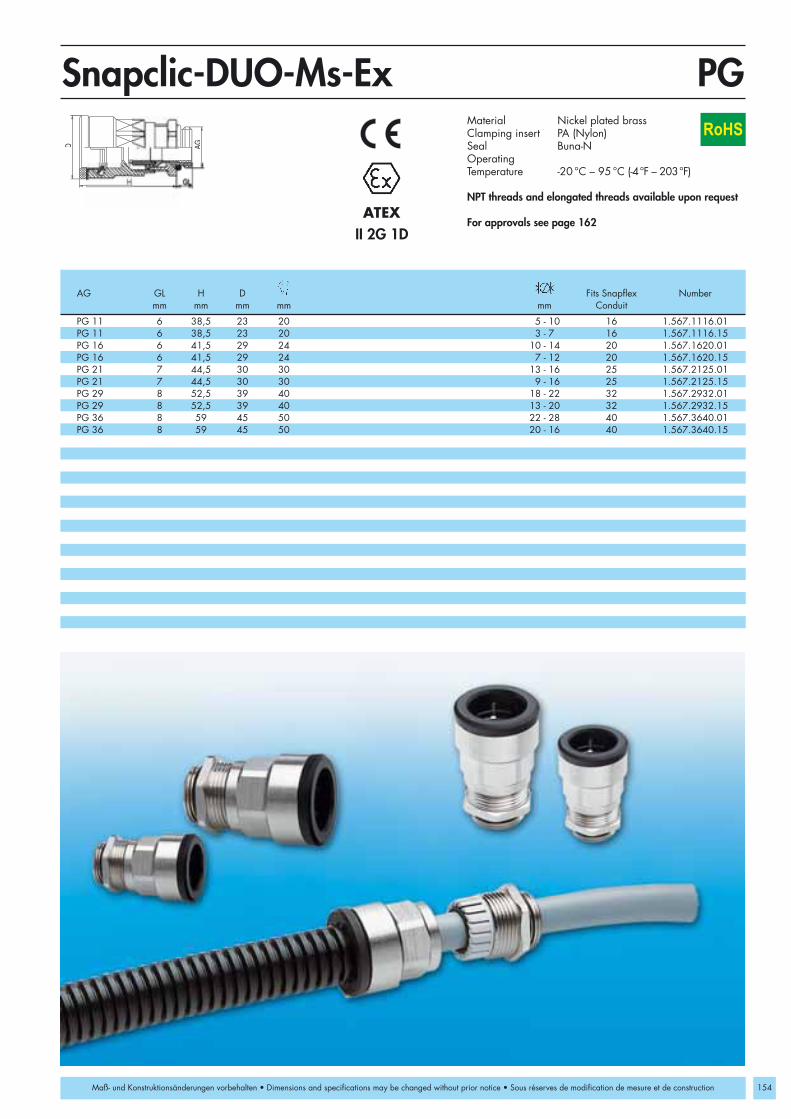
PG 11 6 38,5 23 20 5 - 10 16 1.567.1116.01PG 11 6 38,5 23 20 3 - 7 16 1.567.1116.15PG 16 6 41,5 29 24 10 - 14 20 1.567.1620.01PG 16 6 41,5 29 24 7 - 12 20 1.567.1620.15PG 21 7 44,5 30 30 13 - 16 25 1.567.2125.01PG 21 7 44,5 30 30 9 - 16 25 1.567.2125.15PG 29 8 52,5 39 40 18 - 22 32 1.567.2932.01PG 29 8 52,5 39 40 13 - 20 32 1.567.2932.15PG 36 8 59 45 50 22 - 28 40 1.567.3640.01PG 36 8 59 45 50 20 - 16 40 1.567.3640.15
D AG
PGSnapclic-DUO-Ms-Ex
154
RoHS
II 2G 1DATEX
Maß- und Konstruktionsänderungen vorbehalten • Dimensions and specifications may be changed without prior notice • Sous réserves de modification de mesure et de construction
Material Nickel plated brass Clamping insert PA (Nylon)Seal Buna-NOperatingTemperature -20 °C – 95 °C (-4°F – 203°F)
NPT threads and elongated threads available upon request
For approvals see page 162
AG GL H D Fits Snapflex Numbermm mm mm mm mm Conduit

155
Miscellaneous conduit fitting systems made of plastic or nickelplated brass for general applications in machine tool andequipment manufacturing.
The conduit fitting system EH is universal and can be adaptedto nearly all common conduit systems.
SM-N Patented quick assembly for conduit
SM-W Patented snap-elbow quick assembly for conduit
SM-WS Conduit for the patented SM system
UH Mounting brackets
EH Conduit fitting made of nylon 6/6
EH-W 90° Elbow conduit fittings made of nylon 6/6
KF-W Snap-flange
HSK-EH Combined conduit / strain relief fittings made of nylon 6/6
Conduit Fittings
Setting Standards

156
M 16 x 1,5 8 23 17 10 1.511.1600.50 1.511.1601.50M 20 x 1,5 9 28 24 14 1.511.2000.50 1.511.2001.50M 25 x 1,5 11 32 35 23 1.511.2500.50 1.511.2501.50M 32 x 1,5 11 35 42 29 1.511.3200.50 1.511.3201.50
PG 9 8 23 17 10 1.511.0900.14 1.511.0901.14PG 11 8 25 21 12 1.511.1100.14 1.511.1101.14PG 13,5 9 28 24 14 1.511.1300.14 1.511.1301.14PG 16 10 29 27 17 1.511.1600.14 1.511.1601.14PG 21 11 32 35 23 1.511.2100.14 1.511.2101.14PG 29 11 35 42 29 1.511.2900.14 1.511.2901.14PG 36 13 41 50 37 1.511.3600.14 1.511.3601.14PG 48 14 46 64 50 1.511.4800.14 1.511.4801.14
NPT 3/8" 15 23 17 10 1.511.3800.70 1.511.3801.70NPT 1/2" 13 29 27 17 1.511.1216.70 1.511.1217.70NPT 3/4" 13 32 35 23 1.511.3400.70 1.511.3401.70NPT 1" 15 35 42 29 1.511.1000.70 1.511.1001.70
GL H
AG
Metr./PG/NPTSM-NM
RoHS
Maß- und Konstruktionsänderungen vorbehalten • Dimensions and specifications may be changed without prior notice • Sous réserves de modification de mesure et de construction
Material PA (Nylon)Protection IP 54 (NEMA 2)
with optional O-Ring and in case of fixed mounting IP 65
OperatingTemperature -20 °C – 80 °C (-4 °F – 176 °F)Colors grey RAL 7031
black RAL 9005
Fits toAG GL H SM-Conduit Number Number
mm mm mm DN grey black

M 16 x 1,5 8 23 43 19 10 1.513.1601.50M 20 x 1,5 9 30,5 52 24 14 1.513.2001.50M 25 x 1,5 11 40 70 33 23 1.513.2501.50M 32 x 1,5 11 51,5 83 42 29 1.513.3201.50
PG 9 8 23 43 19 10 1.513.0901.14PG 11 8 27 48 22 12 1.513.1101.14PG 13,5 9 30,5 52 24 14 1.513.1301.14PG 16 10 32,5 56 27 17 1.513.1601.14PG 21 11 40 70 33 23 1.513.2101.14PG 29 11 51,5 83 42 29 1.513.2901.14
NPT 3/8" 15 23 43 19 10 1.513.3801.70NPT 1/2" 13 32,5 56 27 17 1.513.1217.70NPT 3/4" 13 40 70 33 23 1.513.3401.70NPT 1" 15 51,5 83 42 29 1.513.1001.70
L
AG
HG
L
Metr./PG/NPTSM-WM
157
RoHS
Maß- und Konstruktionsänderungen vorbehalten • Dimensions and specifications may be changed without prior notice • Sous réserves de modification de mesure et de construction
Material PA (Nylon)O-Ring Buna-NProtection IP 54 (NEMA 2)
in case of fixed mounting IP 65OperatingTemperature -20 °C – 80 °C (-4 °F – 176 °F)Colors black RAL 9005
Fits to AG GL H L SM-Conduit Number
mm mm mm mm DN

158
10 PA 10 13 1.510.0900.14 1.510.0901.14 10 30 23 12,5 4 6,5 1.724.0900.11 1.724.0901.1112 PA 12 15,5 1.510.1100.14 1.510.1101.14 12 30 23 12,5 4 6,5 1.724.1100.11 1.724.1101.1114 PA 14 18,5 1.510.1300.14 1.510.1301.1417 PA 16,5 21 1.510.1600.14 1.510.1601.14 17 35 30 15,0 5 6,5 1.724.1600.11 1.724.1601.1123 PA 22,5 28,5 1.510.2100.14 1.510.2101.14 23 42 38 16,0 6 11,5 1.724.2100.11 1.724.2101.1129 PA 28,5 34,5 1.510.2900.14 1.510.2901.14 29 51 49 16,0 6 11,5 1.724.2900.11 1.724.2901.1137 PA 36 42 1.510.3600.14 1.510.3601.14 37 61 51 18,0 6 11,5 1.724.3600.11 1.724.3601.1150 PA 47,5 54 1.510.4800.14 1.510.4801.14 50 74 64 19,0 6 11,5 1.724.4800.11 1.724.4801.11
10 PE 10 13 1.520.0900.14 1.520.0901.1412 PE 12 15,5 1.520.1100.14 1.520.1101.1414 PE 14 18,5 1.520.1300.14 1.520.1301.1417 PE 16,5 21 1.520.1600.14 1.520.1601.1423 PE 22,5 28,5 1.520.2100.14 1.520.2101.1429 PE 28,5 34,5 1.520.2900.14 1.520.2901.1437 PE 36 42 1.520.3600.14 1.520.3601.1450 PE 47,5 54 1.520.4800.14 1.520.4801.14
Dd B
H T
aM
DNSM-WS-PA/PE/UHSM-WS-PA/PE UH
RoHS
Maß- und Konstruktionsänderungen vorbehalten • Dimensions and specifications may be changed without prior notice • Sous réserves de modification de mesure et de construction
Size Type d D Number Number Size B H T M a Number NumberDN mm mm grey black DN mm mm mm mm mm grey black
Material PA (Nylon) / PE /PVDFOperating -40°C – 110°C (PA)/
-40°C – 80°C (PE)Temperature -50 °C – 150°C (PVDF)Colors grey RAL 7011, black RAL 9005
(for PVDF available upon request)
Mounting bracket UHMaterial PAOperating Temperature -40 °C – 110 °CColors grey RAL 7011
black RAL 9005SM-WS-PA/PE Mounting bracket UH

EHPG 7 13 - 15 8 10,5 19/22 10 1.220.0715.11 1.220.0715.12PG 9 13 - 15 8 10,5 19/22 10 1.220.0915.11 1.220.0915.12PG 9 15 - 17 8 10,5 22/24 12 1.220.0917.11 1.220.0917.12PG 9 19 - 21 8 10,5 27/30 17 1.220.0921.11 1.220.0921.12PG 11 15 - 17 8 14 22/24 12 1.220.1117.11 1.220.1117.12PG 11 19 - 21 8 14 27/30 17 1.220.1121.11 1.220.1121.12PG 13,5 19 - 21 8 14,5 27/30 17 1.220.1321.11 1.220.1321.12PG 16 19 - 21 8 17,1 27/30 17 1.220.1621.11 1.220.1621.12PG 21 26 - 29 10 23 36/38 23 1.220.2128.11 1.220.2128.12PG 29 33 - 36 10 31 46 29 1.220.2936.11 1.220.2936.12PG 36 42 - 46 12 39,5 55 37 1.220.3646.11 1.220.3646.12PG 48 52 - 58 12 51,5 65 50 1.220.4858.11 1.220.4858.12
EH-WPG 9 13 - 15 8 24 57 22 10 1.223.0915.11 1.223.0915.12PG 11 15 - 17 8 29 64 24 12 1.223.1117.11 1.223.1117.12PG 13,5 19 - 21 10 33 68 30 17 1.223.1321.11 1.223.1321.12PG 16 19 - 21 10 33 68 30 17 1.223.1621.11 1.223.1621.12PG 21 26 - 29 11 41 79 38 23 1.223.2128.11 1.223.2128.12PG 29 33 - 36 11 55 95 46 29 1.223.2936.11 1.223.2936.12
GL
AG
A
GL
H
L
AG
PGEH/EH-W
159
RoHS
Maß- und Konstruktionsänderungen vorbehalten • Dimensions and specifications may be changed without prior notice • Sous réserves de modification de mesure et de construction
Material PA (Nylon)Protection IP 65OperatingTemperature -30 °C – 100 °C (-22 °F – 212 °F)Colors grey RAL 7035
black RAL 9005
Fittings with metric threads available upon request
Fits toAG GL A H L SM-Conduit Number Number
mm mm mm mm mm mm DN grey black

160
12 4 49 47 37 15 29,5 35 1.312.1100.15 1.312.1101.1517 4 49 47 37 15 29,5 35 1.312.1600.15 1.312.1601.1523 6 69 65 52 21 42 44 1.312.2100.15 1.312.2101.1529 6 90 78 65 65 55 1.312.2900.15 1.312.2901.1537 6 100 94 80 80 66 1.312.3600.15 1.312.3601.1550 6 116 101 88 90 76 1.312.4800.15 1.312.4801.15
Ø mm
DE
C
B
A F
C
B
A
H
DNKF-WRoHS
Maß- und Konstruktionsänderungen vorbehalten • Dimensions and specifications may be changed without prior notice • Sous réserves de modification de mesure et de construction
Material PA (Nylon) Seal Buna-NProtection IP 65OperatingTemperature -20 °C – 80 °C (-4 °F – 176 °F)Colors grey RAL 7011
black RAL 9005
Fits toSM-Conduit Ø A B C D F H Number Number
DN mm mm mm mm mm mm mm grey black

M 16 x 1,5 8 44 19/22 4 - 8 13 - 15 10 1.224.1615.52M 20 x 1,5 9 49 24/30 6 - 12 19 - 21 17 1.224.2021.52M 25 x 1,5 11 59 33/38 13 - 18 26 - 29 23 1.224.2518.52
PG 9 8 44 19/22 4 - 8 13 - 15 10 1.224.0915.11 1.224.0915.12PG 11 8 47 22/24 5 - 10 15 - 17 12 1.224.1117.11 1.224.1117.12PG 13,5 9 49 24/30 6 - 12 19 - 21 17 1.224.1321.11 1.224.1321.12PG 16 10 50 27/30 10 - 14 19 - 21 17 1.224.1621.11 1.224.1621.12PG 21 11 59 33/38 13 - 18 26 - 29 23 1.224.2128.11 1.224.2128.12
3/8” NPT 15 51 19/22 4 - 8 13 - 15 10 1.224.3815.721/2” NPT 13 53 24/30 6 - 12 19 - 21 17 1.224.1221.723/4” NPT 13 61 33/38 13 - 18 26 - 29 23 1.224.3418.72
AG
GLH
Metr./PG/NPTHSK-EHM
161
RoHS
Maß- und Konstruktionsänderungen vorbehalten • Dimensions and specifications may be changed without prior notice • Sous réserves de modification de mesure et de construction
Material PA (Nylon)Seal Buna-NProtection IP 65OperatingTemperature -40 °C – 110 °C
(-40 °F – 212 °F)Colors grey RAL 7035
black RAL 9005
Fits toAG GL H Cable Conduit SM-Conduit Number Number
mm mm mm mm mm DN grey black

162
104 RSD-Ms-Ex 1.078.* -20 °C – 95 °C x x DMT 03 ATEX E 049104 RSD-Ms-Ex 1.079.* -60 °C – 180 °C x x DMT 03 ATEX E 049106 RSD-INOX-Ex 1.098.* -20 °C – 180 °C x x DMT 03 ATEX E 049106 RSD-INOX-Ex 1.099.* -60 °C – 180 °C x x DMT 03 ATEX E 049105 V-INOX-Ex 1.192.* -20 °C – 95 °C x x DMT 03 ATEX E 049105 V-INOX-FPM-Ex 1.193.* -20 °C – 180 °C x x DMT 03 ATEX E 049105 V-INOX-VMQ-Ex 1.194.* -60 °C – 180 °C x x DMT 03 ATEX E 049103 V-Ms-Ex 1.197.* -20 °C – 95 °C x x DMT 03 ATEX E 049103 V-Ms-FPM-Ex 1.198.* -20 °C – 180 °C x x DMT 03 ATEX E 049103 V-Ms-VMQ-Ex 1.199.* -60 °C – 180 °C x x DMT 03 ATEX E 04988 HSK-K-MZ-Ex 1.215.* -20 °C – 70 °C x x KEMA 99 ATEX 6971 X72, 74, 76, 78, 80 HSK-K-Ex 1.291.* -20 °C – 95 °C x x DMT 02 ATEX E 047 X72, 74 HSK-K-Ex 1.295.* -20 °C – 95 °C x x DMT 02 ATEX E 047 X100 HSK-V-Ex 1.296.* -20 °C – 95 °C x x BVS 03 ATEX E 298101, 102 V-Ex 1.297.* -20 °C – 90 °C x x DMT 03 ATEX E 049153/154 Snapclic-Duo-Ms-Ex 1.566.*/1.567.* -20 °C – 95 °C x x BVS 06 ATEX E 069 X152 Snapflex-Ex 1.560.* -20 °C – 95 °C x x BVS 06 ATEX E 069 X82 HSK-K-Multi-Ex 1.599.* -20 °C – 95 °C x x DMT 02 ATEX E 047 X73, 75, 77, 79, 81/ 66, 67 HSK-M/EMV-Ex 1.610.* / 1.616.* -20 °C – 95 °C x x DMT 03 ATEX E 051 X89, 90 / 70 HSK-MZ/EMV-Ex 1.611.* / 1.617.* -20 °C – 95 °C x x DMT 03 ATEX E 051 X86, 87 HSK-INOX-Ex 1.612.* -20 °C – 95 °C x x DMT 03 ATEX E 051 X92, 93 HSK-M-Ex-d 1.622.* -60 °C – 105 °C x x KEMA 99 ATEX 6968 X92, 93 HSK-MZ-Ex-d 1.628.* -60 °C – 105 °C x x KEMA 99 ATEX 6968 X94, 95 HSK-INOX-Ex-d 1.632.* -60 °C – 105 °C x x KEMA 99 ATEX 6968 X94, 95 HSK-INOX-PVDF-Ex-d 1.633.* -20 °C – 130 °C x x KEMA 99 ATEX 6968 X92, 93 HSK-M-PVDF-Ex-d 1.634.* -20 °C – 130 °C x x KEMA 99 ATEX 6968 X68, 69 HSK-M-EMV-D-Ex 1.636.* -20 °C – 95 °C x x DMT 03 ATEX E 051 X68, 69 HSK-M-EMV-D-Ex 1.637.* -60 °C – 105 °C x x KEMA 99 ATEX 6971 X73, 75, 77, 79, 81/ 66, 67 HSK-M/EMV-Ex 1.640.* / 1.646.* -60 °C – 105 °C x x KEMA 99 ATEX 6971 X89, 90 / 70 HSK-MZ/EMV-Ex 1.641.* / 1.647.* -60 °C – 105 °C x x KEMA 99 ATEX 6971 X86, 87 HSK-INOX--Ex 1.642.* -60 °C – 105 °C x x KEMA 99 ATEX 6971 X73, 75, 77, 79, 81 HSK-M-PVDF-Ex 1.660.* -20 °C – 130 °C x x KEMA 99 ATEX 6971 X89, 90 HSK-MZ-PVDF-Ex 1.661.* -20 °C – 130 °C x x KEMA 99 ATEX 6971 X86, 87 HSK-INOX--PVDF-Ex 1.662.* -20 °C – 130 °C x x KEMA 99 ATEX 6971 X66, 67 HSK-M-EMV-PVDF-Ex 1.666.* -20 °C – 130 °C x x KEMA 99 ATEX 6971 X70 HSK-MZ-EMV-PVDF-Ex1.667.* -20 °C – 130 °C x x KEMA 99 ATEX 6971 X83 HSK-M-Multi-Ex 1.687.* -20 °C – 95 °C x x DMT 03 ATEX E 051 X98 V-Ms-/INOX-Ex-d 1.875.*/1.895.* -20 °C – 95 °C x x KEMA 06 ATEX 002498 V-Ms-/INOX-FPM-Ex-d1.876.*/1.896.* -20 °C – 180 °C x x KEMA 06 ATEX 002498 V-Ms-/INOX-VMQ-Ex-d1.877.*/1.897.* -60 °C – 180 °C x x KEMA 06 ATEX 002496/97 RSD-Ms-/INOX-Ex-d 1.878.*/1.898.* -20 °C – 95 °C x x KEMA 06 ATEX 002496/97 RSD-Ms-/INOX-Ex-d 1.879.*/1.899.* -60 °C – 180 °C x x KEMA 06 ATEX 0024
IECEx KEM 07.0012 IECEx KEM 07.0013X IECEx KEM 07.0014X IECEx BVS 07.0019XIECEx BVS 07.0020X IECEx BVS 07.0021 IECEx BVS 07.0022X IECEx KEM 06.0056
Other temperature ranges pending. You may find further info at: www.hummel.com
Page Article Number Temperature Range Approval G Approval D EC-Type Examination Certificate(Gas) (Dust)
Hungary BKI 03 ATEX 001 XBKI 03 ATEX 002 X
Russia PCT 7454206PPC 00-27485
China CQST CNEx06.1147UCQST CNEx06.1148U
Brazil INMETRO MC AEX-4665-X INMETRO MC AEX-6203-XINMETRO MC AEX-5233-X INMETRO MC AEX-6410-XINMETRO MC AEX-5234-X INMETRO MC AEX-6411-XINMETRO MC AEX-5235 INMETRO MC AEX-6412-XINMETRO MC AEX-8528 INMETRO MC AEX-8822-X
Product Material Abbreviations
Other International Ex-Certifications Installation InstructionsMulti hole inserts: Cable diameter should not be less than 20% of hole dia-meter and the difference between cable diameter and hole should neverexceed 1mm (.04“).
Flat cable inserts: Actual dimensions of cables and wires must be verified with the respective cable supplier.
Technical Information
Approvals for HSK Strain Relief Fittings/ Licence Number 40012033
CR Chloroprene rubberFPM FluorelastomerMs Nickel plated brassNBR Buna-NPA NylonPE Polyethylene
PP PolypropylenePVC PolyvinylchloridePVDF PolyvinylidenfluorideSB Styrene ButadieneVMQ Silicone
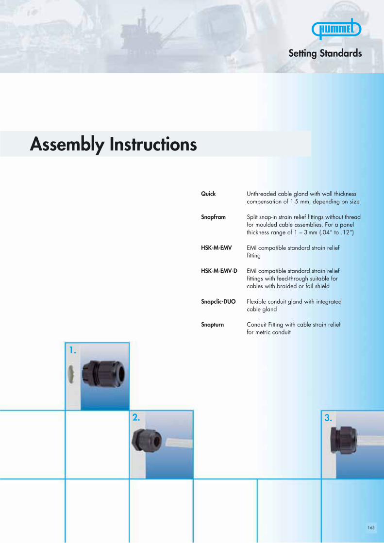
163
1.
2. 3.
Quick Unthreaded cable gland with wall thicknesscompensation of 1-5 mm, depending on size
Snapfram Split snap-in strain relief fittings without threadfor moulded cable assemblies. For a panelthickness range of 1 – 3mm (.04“ to .12“)
HSK-M-EMV EMI compatible standard strain relieffitting
HSK-M-EMV-D EMI compatible standard strain relieffittings with feed-through suitable for cables with braided or foil shield
Snapclic-DUO Flexible conduit gland with integrated cable gland
Snapturn Conduit Fitting with cable strain relief for metric conduit
Assembly Instructions
Setting Standards

164
�
�
��
Quick
Quick
Pushinto hole
FinishedTightennut
The strain relieffitting withoutthread
Insertcable
Assembly without tools. No locknut is needed!
1. Push Quick into mounting hole
2. Insert cable and pull back slightly
3. Hold Quick against the housing and tighten the nut – finished!
Assembly Instructions

165
456 123
Snapfram
Assembly Instructions
cabel assembly withmoulded plug
1. Slide bushing (5) and O-ring (6) over cable assembly with moulded plug.
2. Pry the slit adapter (4) and slit clamping ring (3) open and slide over cable.
3. Peel off the multiperforated rings of the slit seal ring (2) until it matches the cable diameter.Slide over cable.
4. Fold the individual parts together and slide inside bushing (5).
5. Slide the slit jam nut (1) around the cable and finger tighten into bushing (5).
6. Push Snapfram into the panel hole and tighten the jam nut.
The slit fitting for moulded cable assemblies
panel

166
�
�
�
HSK-M-EMVHSK-M-EMV
+ Strip cable+ Expose braided shield
+ Push clamping insert into bodyand tighten dome nut
+ Assemble into housing+ Finished!
Step 2
Step 3
Step 1
+ Feed cable through dome nutand clamping insert
+ Fold braided shield over clamping insert+ Make sure that braided shield
overlaps the O-Ring by 3/32“ (2mm)
Assembly Instructions

167
HSK-M-EMV-DHSK-M-EMV-D
Assembly Instructions
Option 1
Option 2
Feed-through of shield (braided or foil)
+ Remove cable jacket to expose the shield as required+ Insert cable into fitting until the shield reaches
the contact position+ Tighten dome nut
Option 3
Termination of the braided shield in the fitting
+ Strip cable jacket and braided shield to different lengths+ For small diameter cables fold the braided shield back
over the cable jacket+ Insert cable into fitting until the shield reaches
the contact position+ Tighten dome nut
Feed-through of cable and shield (braided or foil)
+ Expose shield approximately 7/16“ (10mm)+ Insert cable into fitting until the shield reaches
the contact position+ Tighten dome nut
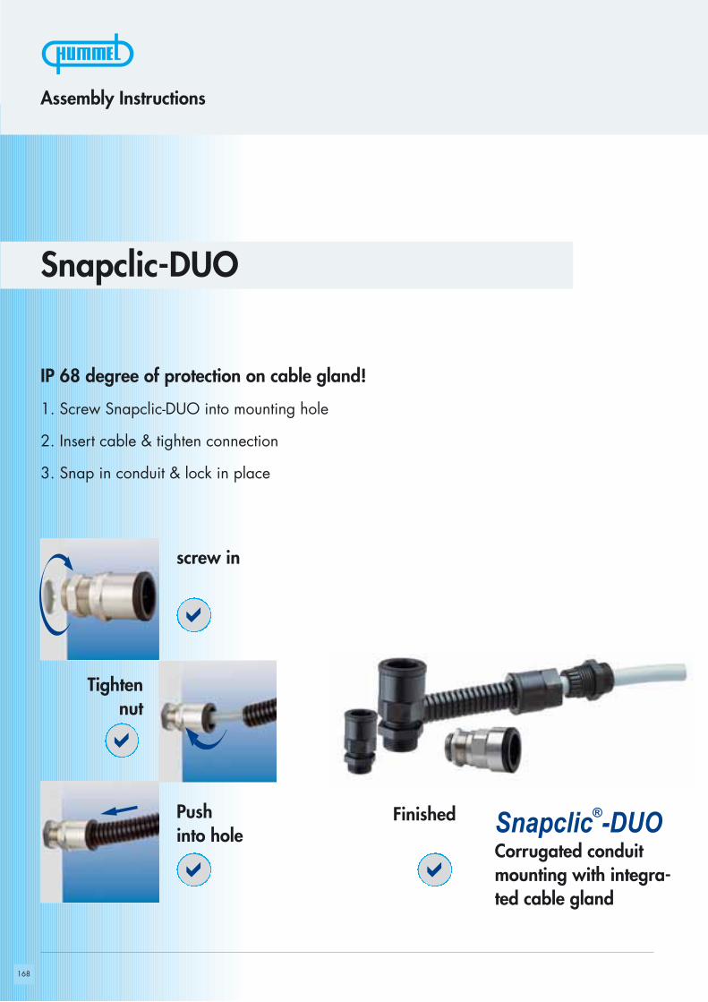
168
�
�
��
Snapclic®-DUO
screw in
FinishedPushinto hole
Corrugated conduitmounting with integra-ted cable gland
Tightennut
Assembly Instructions
IP 68 degree of protection on cable gland!
1. Screw Snapclic-DUO into mounting hole
2. Insert cable & tighten connection
3. Snap in conduit & lock in place
Snapclic-DUO
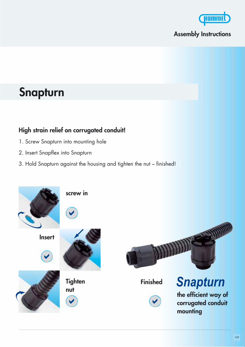
169
�
�
��
Snapturn
Snapturn
screw in
FinishedTightennut
Insert
Assembly Instructions
High strain relief on corrugated conduit!
1. Screw Snapturn into mounting hole
2. Insert Snapflex into Snapturn
3. Hold Snapturn against the housing and tighten the nut – finished!
the efficient way of corrugated conduitmounting
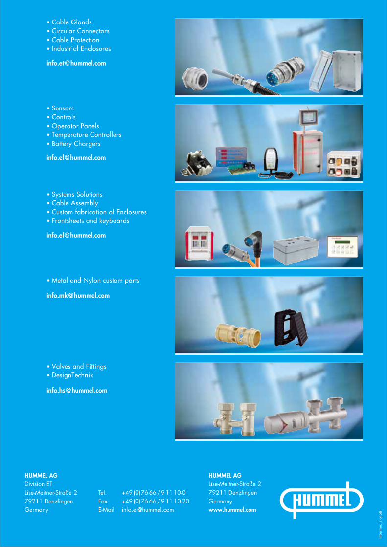
inte
rmed
ia �
���
Tel. +49 (0)7666/91110-0Fax +49 (0)7666/91110-20E-Mail [email protected]
HUMMEL AGLise-Meitner-Straße 279211 DenzlingenGermanywww.hummel.com
• Cable Glands• Circular Connectors• Cable Protection• Industrial Enclosures
• Sensors• Controls• Operator Panels• Temperature Controllers• Battery Chargers
• Systems Solutions• Cable Assembly• Custom fabrication of Enclosures• Frontsheets and keyboards
• Metal and Nylon custom parts
• Valves and Fittings• DesignTechnik
HUMMEL AGDivision ETLise-Meitner-Straße 279211 DenzlingenGermany