kemel air seal type kemel ax instruction manual · air seal system is in operation when blowing air...
TRANSCRIPT

KEMEL AIR SEAL
Type KEMEL AX
INSTRUCTION MANUAL
Marine Division
http://www.kemel.com
This manual is produced based on a typical lubrication diagram for stern tube system installed with Type KEMEL AX seals. For correct understanding and operation of the ship’s system, read this booklet together with seal drawing and the piping diagram available in the finished plan. Besides this booklet, read Instruction Manual for KEMEL COMPACT SEAL Type KEMEL CX, DX & AX included in the finished plan.

- 1 -
Contents
1. Outline -------------------------------------- P. 2
1.1 Construction
1.2 Air Control Unit (MU)
1.3 AFT Seal 1.4 S/T L. O. Tank Unit (TU) 1.5 Oil Pressure Unit (OU) 1.6 Drain Collection Unit (CU)
2. Oil Filling & Oil Pressure Test -------------------------------------- P. 5
3. Operation of Air Seal -------------------------------------- P. 5
3.1 Start-up Air Control Unit (MU) 3.2 Operation of Air Seal
4. Daily Maintenance ------------------------------------- P. 8
4.1 Stern Tube System
4.2 Air Control Unit & Drain Collection Unit
5. Trouble Shooting ------------------------------------ P. 10
5.1 Abnormalities of Air Pressures/Air Flow & Actions
5.2 Alarms & Actions
5.3 Other abnormalities & Actions
6. Switch-over to normal Oil Seal System for emergency ---------------- P. 13
7. Operation for Dry-docking, Undocking and Laying-up ---------------- P. 14
7.1 Dry docking & Undocking
7.2 Laying-up

- 2 -
1. Outline
1.1 Construction
Air Seal keeps seawater out by blowing air into sea through an air chamber (Air Chamber) provided at the space between the #2 & 3 seal rings in AFT seal, and it keeps oil tight by controlling stern tube oil pressure to follow change of ship’s draft. Segregation of seawater and stern tube oil by Air Chamber minimize the risk of seawater contamination. Besides, a drain line provided at the bottom of Air Chamber collects and recovers leaking oil and water in engine room in case of leakage. At the same time, the system automatically optimizes the oil pressure based on draft pressure detected at Air Chamber and remarkably reduces the pressure load given on AFT seal at all draft levels. The construction of Type DX seal with a stand-by spare seal ring is employed on AFT seal, which enables switching-over to the spare at any time by simple valve operation. FWD seal has a same construction as existing models. The schematic diagram and the components for the system are shown in the sketch below.
Component Function
Air Control Unit (MU)
Supply air to AFT seal Regulate supply air pressure
Regulate air flow
Pressurize S/T L. O. Tank
Clean air pipe by fresh water
S/T L. O. Tank Unit (TU)
Supply oil to Pump
Pressurize stern tube
Oil Pressure Unit (OU)
Circulate stern tube oil - Pump
Drain Collection Unit(CU)
Recover leaking oil/water Recover cleaning fresh water
FWD seal L. O. Circulation Unit
Circulate FWD seal L. O.

- 3 -
Air Flow
meter FM1
Air Source
Pressure P1Blowing Air
Pressure P4
Air Regulator SUB
R2 & P3
Air Regulator
MAIN R1 & P2
MAIN/SUB
Change Lever C1
Air Filters
F1・F2
MU Front View
Air Flow Controller -
MAIN FC1
MU Side View Left
Air Flow Controller
FC2
MU Side View Right
Air Filter Drain Drain
Fresh Water Line F/W
TU Line OUT2
Air Blow Line OUT1
Air Source IN
MU View Bottom Panel
Test Line OUT3
DifferentialPressure Gauge
DP
1.2 Air Control Unit (MU) Air Control Unit (MU) regulates supplied compressed air at the pressure*) set by Air Regulator (R1) and at the
flow rate*) set by Air Flow Controller (FC1) after passing Air Filters (F1 & F2). Then the regulated air lead to Air Chamber in AFT seal is blown into sea, called Air Blow Line which has a branch line to S/T L. O. Tank Unit (TU), called TU Line, to pressurize it. MU has a spare Air Regulator (R2) and a spare Air Flow Controller (FC2) on SUB LINE for switching over from R1 & FC1 on MAIN LINE by C1 Lever. Also MU has Fresh Water Line for periodical cleaning of air purging pipe and has an Alarm Switch for Air Pressure Low. Air Regulators R1 and R2 have pressure gauges P2 and P3 for setting air pressure. Dirtiness of Air Filters (F1 & F2) is examined by visual and Differential Pressure Gauge (DP). The gauge P1 indicates air source pressure and the gauge P4 indicates Air Blow Line pressure. *) Set values of Air Regulators and Air Flow Controllers are shown in “Finished Plan – Piping Diagram Fig. 1”.

- 4 -
Oil Level High/Low
Alarm switches
TU Top View
Oil level
gauge
Drain Valve
(N. C.)
TU Front View
TU Line
connection
Air Vent
(N. C.)
Safety Relief Valve
1.3 AFT Seal Air supplied from MU to AFT Seal blows out underwater through Air Chamber with the pressure set by Air Regulator. The effects of air blow are explained below; 1) When the pressure in Air Chamber slightly exceeds the
tension forces from the #1 & #2 seal rings + seawater pressure from the draft, the air lifts up the #1 & #2 seal lips and starts blowing into sea through the gap, formed by the lift, with the constant flow rate set by Air Flow Controller.
2) The gap by constant air blow makes Air Chamber being kept opened in-water all the time.
3) By this, Air Chamber pressure (= Air Blow Line pressure P4) is equalized to the level of tension forces from the #1 & #2 seal rings + seawater pressure from the draft or slightly above.
Because of the opening underwater, Air Chamber pressure does not go higher up to the pressure set by Air Regulator, and also continual air blowing prevents seawater penetration into Air Chamber. Air Flow Controller keeps constant flow and maintains the gaps under all draft level of the ship. Therefore the pressure in Air Chamber follows water pressure from draft change with no time-delay. In addition, air from MU partly returning to Drain Collection Unit (CU) with slight ventilation in E/R generates low speed air flow to remove leaking oil or water from Air Chamber, through a drain hole provided at the bottom lead into CU.
The #3 & #3S seal rings can be switched over by valve operation in E/R. (Valve “C” & “D” shown in the piping diagram P. 6.) Open these valves for the #3 in use and close them for the #3S in use.
1.4 S/T L. O. Tank Unit (TU) TU is an air-tight oil tank having 100 - 200L capacity and is installed to give oil head pressure in stern tube with 2 - 2.5M of the oil height above shaft centerline. In addition, TU is connected with an air pipe comes out from Air Blow Line to transmit the pressure in Air Chamber. By the arrangement, stern tube is pressurized at the level of oil head pressure + Air Chamber Pressure which is loaded onto the #3 seal ring supported at the same time by Air Chamber Pressure from seawater side while air blows out as described in Article 1.3. Because of Air Chamber Pressure at the front face and the back of the #3 seal ring, it counteracts each other cancelling the force. As a result, the actual load remains on the #3 seal ring is oil head pressure of TU constant at all draft. Same effect is available on the #3S seal ring when it is in use. TU is provided with Safety Relief Valve to avoid excessive pressure, and Alarm Switches for Oil Level High & Low. TU is also connected with Oil Pressure Unit (Oil pumps) to circulate stern tube oil.

- 5 -
1.5 Oil Pressure Unit (OU – Oil Pump) OU circulates lubrication oil via “OU ➔ Stern Tube ➔ TU ➔ OU”. Stern tube oil pressure is measured at the return line from stern tube to TU. The correct pressure is calculated by adding (or deduction on some cases) oil head pressure from the gauge height to the reading value. (See calculation example in P.7.) Periodically examine oil suction & discharge pressures on the pumps, and clean strainers for maintenance whenever is necessary.
1.6 Drain Collection Unit (CU)
CU is an air-tight tank with 10L capacity and is located below the shaft level. CU is connected to a drain pipe from Air Chamber in AFT seal. Flow Controller (FC) fitted on CU gives air-flow at a low speed (about 5 L/min.) from Air Chamber towards CU to removes leaking seawater and oil into CU through the pipe. Drain recovered can be discharged by the air pressure in CU, through Drain Valve. (Discharge drain while M/E is stopped.) CU is fitted with Level Gauge and High Level Alarm Switch.
2. Oil Filling and Oil Pressure Test Procedures for oil filling to stern tube and oil pressure test for Air Seal is described in P. 6. Confirm actual valve operation for oil filling, circulation, draining & etc. in ship’s piping diagram available in finished plan.
3. Operation of Air Seal 3.1 Start-up Air Control Unit (MU)
When air supply to Air Seal become available, start-up MU after filling oil in stern tube by the procedures below, 1) Put valve positions in MU for blowing air as per Finished Plan – Piping Diagram Fig. 1. 2) Close Air Vent on TU and Drain Valve on CU. 3) Put valve positions for oil circulation via “TU ➔ OU ➔ Stern Tube ➔ TU”, then start-up OU. 4) Open air source valve for MU. 5) Adjust settings for Air Regulator R1 and Air Flow Controller FC1 if necessary. 6) Confirm air blowing at AFT seal in dry-dock, or at sea surface in stern area after launching. 7) Record all data by using the form shown in P. 7, and examine the system is working right. 8) Adjust stern tube oil pressure Ps/t by operating bypass valve on OU if necessary. 9) Put Change Lever C1 on SUB and examine all pressures. (FM1 does not work with SUB in use.) 10) Put Change Lever C1 on MAIN for normal operation.
In case of launching a new ship with no air blowing, examine CU periodically for possible water penetration after floatation.
3.2 Operation of Air Seal Air Seal System is in operation when blowing air into sea is started. The system automatically controls stern tube oil pressure at the optimum level responding to changes of ship’s draft. Keep blowing air and operating OU all the time while the ship at sea as well as at berth or anchor. OU may be stopped for maintenance etc. while M/E is stopped. In case air source is shut off, stern tube oil pressure stays at the level of oil head pressure from TU. Closely watch seawater penetration into CU in such an event, and recover or establish air supply as soon as possible. Maintenance of stern tube system, MU and CU is done as per the article 4 in P. 8.
Level
Gauge
Air Flow Controller FC
CU
High Level
Alarm Switch
Joint for AFT seal drain pipe
Drain Valve
(N. C.)
Air Vent

- 6 -
TYPICAL DIAGRAM - Confirm valve no.s & details in Finished PlanTest
Orde
Seal
RingProcedure
1 #3S
1) Fill stern tube and TU with oil. - See left "Procedure Oil Filling".
2) Keep valves "C" & "D" closed.
3) Apply oil pressure in stern tube.
4) Remove bottom plug between #3 & 3S seal rings on AFT seal casing.
5) Clean up seal casing/liner/oil holes to remove oil wet.
6) Leave the plug opened for more than 3 hours.
7) Confirm no oil leaking through the bottom hole.
8) Confirm no oil leaking at other area, i. e. sheet packing, "O" ring & etc.
2 #4
1) Same procedures as 1) & 2) for testing #3S above.
2) Remove bottom plug between #4 & 5 seal rings on FWD seal casing.
3) Clean up seal casing/liner/oil holes to remove oil wet.
4) Leave the plug opened for more than 3 hours.
5) Confirm no oil leaking through the bottom hole.
6) Confirm no oil leaking at other area, i. e. sheet packing, "O" ring & etc.
3 #3
1) Plug all oil holes/drain holes between #3 & 3S on AFT seal casing.
2) Open valves "C" & "D", to apply pressure in #3/3S chamber.
3) Close valve "H" for about 30 sec. to direct oil flows into #3/3S chamber.
4) Keep valve "H" open again for the test.
5) Remove bottom plug between #2 & 3 on AFT seal casing.
6) Clean up seal casing/liner/oil holes to remove oil wet.
7) Leave the plug opened for more than 3 hours.
8) Confirm no oil leaking through the bottom hole.
4 #2
1) Leave bottom plug between #2 & 3 opened.
2) Plug bottom hole between #1 & 2.
3) Remove two plugs on top between #1 & 2, for filling and air venting.
4) Fill #1/2 chamber with "Fresh Water" through the top hole.
5) Clean up seal casing/liner/filling holes to remove wet.
6) Confirm no water leaking through the bottom hole between #2 & 3.
5 #1
1) Same procedures 1) - 5) for testing #2 seal ring above.
2) Confirm no water leaking out.
3) Drain out Fresh Water after the test.
4) Confirm all holes for filling, draining & air venting on AFT seal plugged.
6 #5
1) Plug all holes between #4 & 5 on FWD seal casing.
2) Fill #4/5 chamber with oil.
3) Clean up seal casing/liner to remove oil wet.
4) Confirm no oil leaking out.
5) Confirm all oil holes on FWD seal plugged after the test.
LEAK TEST PROCEDURE in dry-dock (AIR Seal Type AX)
REMARKS
1. Carry out leak test after completion of flushing pipes.
2. Take wear-down readings before and after overhauling AFT seal, for repair ship.
3. Protect seals from sand blasting, painting, welding, chemicals, excessive heat & etc.
4. Use stainless steel fitting bolts (SUS 316 or equivalent) for AFT seal installation.
5. Secure all the fitting bolts and plugs for AFT seal by using stainless steel wire.
6. Put all valves (and regulator setting) back to "Normal Operating Condition" after the test.7. Check P2 pressure indication for Regulator on the green mark.8. Oil level may suddenly reduce when air-locking dissolved. Fill oil in such an event.
Leak test via "X"-line1) Close valves "A" & "B". 2) Keep valve "G" opened. Keep valves "C" & "D" closed.3) Operate OU4) Circulate oil via Sump Tk➟S/T➟"X"-line➟Sump Tk for test.
Leak test by applying air presssure in MU1) Close valve "G" on oil line.2) Open valves "A", "B" & "H" on oil line.3) Keep valves "C" & "D" closed.4) Close air vent on TU.5) Operate OU, and circulate oil via TU➟S/T➟TU for test.6) Set valve positions in MU are for Air Blow. 7) Reduce Regulator setting (0.2 - 0.4MPa) on "MU" to 0.1MPa.8) 8) Close valve "E", or V4 valve in MU.9) Check Ps/t shows about 0.1MPa and proceed for the test.
Apply oil pressure in stern tube either by X-line or by air pressure, and carry out the test in accordance with the procedure shown in the table.
1. Valve positions shown above are for "Normal Operating Condition" of Air Seal System.
2. "X"-line is for oil circulation via the gravity line, not in use during operation of Air Seal System.
Procedure Oil Filling
1) Fill Sump tank, - Open Valve "I".2) Close air source valve for MU, and open air vent on TU.3) Close valves "C" & "D", and open valve "G".4) Keep valves "A" & "H" open, and close valve "B".5) Fill stern tube and TU with oil by operating OU.6) Stop OU after TU filled up with half level.7) Close air vent on TU.8) Carry out Test Order "1" & "2", either by using;
a) "X"-line, orb) Air pressure
9) Fill oil in #3/3S by Test Order "3" after "1" & "2".10) Fill oil #4/5 by Test Order "6" after "3", "4" & "5".
- 7 -
P1 P2 P3 P4 DP F1 F2 FM1 C1 Pd FC Level gauge Ps/t SUC. DISC.
Air
source
press.
(MPa)
Reg. air
press.
Main
(MPa)
Reg. air
press.
Sub
(MPa)
Blow air
press.
(MPa)
Diff. air
press.
(MPa)
Air filterOil mist
filter
Air flow
meter
(L/min.)
Change
lever
Air
press.
(MPa)
Air flow
control
Liquid in
tank
Level
from Tk
bottom
(cm)
Level from
Tk bottom
(cm)
S/T oil
press.
(MPa)
Oil
press.
(MPa)
Oil
press.
(MPa)
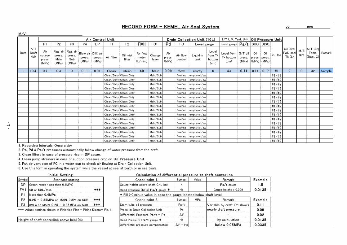
1 10.4 0.7 0.3 0 0.11 0.01 Clean Clean 40 Main 0.09 flow empty 0 43 0.11 0.11 0.17 #1 7 0 32 SampleClean/Dirty Clean/Dirty Main/Sub flow/no empty/oil/sw #1/#2Clean/Dirty Clean/Dirty Main/Sub flow/no empty/oil/sw #1/#2Clean/Dirty Clean/Dirty Main/Sub flow/no empty/oil/sw #1/#2Clean/Dirty Clean/Dirty Main/Sub flow/no empty/oil/sw #1/#2Clean/Dirty Clean/Dirty Main/Sub flow/no empty/oil/sw #1/#2Clean/Dirty Clean/Dirty Main/Sub flow/no empty/oil/sw #1/#2Clean/Dirty Clean/Dirty Main/Sub flow/no empty/oil/sw #1/#2Clean/Dirty Clean/Dirty Main/Sub flow/no empty/oil/sw #1/#2Clean/Dirty Clean/Dirty Main/Sub flow/no empty/oil/sw #1/#2Clean/Dirty Clean/Dirty Main/Sub flow/no empty/oil/sw #1/#2Clean/Dirty Clean/Dirty Main/Sub flow/no empty/oil/sw #1/#2Clean/Dirty Clean/Dirty Main/Sub flow/no empty/oil/sw #1/#2Clean/Dirty Clean/Dirty Main/Sub flow/no empty/oil/sw #1/#2Clean/Dirty Clean/Dirty Main/Sub flow/no empty/oil/sw #1/#2Clean/Dirty Clean/Dirty Main/Sub flow/no empty/oil/sw #1/#2Clean/Dirty Clean/Dirty Main/Sub flow/no empty/oil/sw #1/#2
5. Put air vent pipe of FC in a water cup to check air flowing at Drain Collection Unit.
Symbol Symbol Value
DP h
FM1 Hp
P1
P2 Symbol MPa
P3 Ps/t
*** Adjust settings shown in Finishied Plan - Piping Diagram Fig. 1. Pd
ΔP
Hp
ΔP + Hp
Remark
S/T B'rg
Temp.
(Deg.. C)
Oil Pressure Unit
3. Clean filters in case of pressure rise in DP gauge.
M/E
rpmin Use
Drain Collection Unit (10L) S/T L.O. Tank Un it
Date
1. Recording intervals; Once a day
Level gauge
RECORD FORM - KEMEL Air Seal System
M/V
2. P4, Pd & Ps/t pressures automatically follow change of water pressure from the draft.
Air Control Unit
AFT
Draft
(M)
Ps/t gauge
Standard setting
Green range (less than 0.1MPa)
0.25 - 0 .35MPa on MAIN, 0MPa on SUB ***
More than 0 .4MPa
4. Clean pump strainers in case of suction pressure drop on Oil Pressure Unit .
Calculation of differential pressure at shaft centerl ine
6. Use this form in operating the system while the vessel at sea, at berth or in sea trials.
Check point 2.
Remark
below 0.05MPa
Variable by draft. Pd shows
nearly draft pressure.
-
Initial Setting
0MPa on MAIN, 0 .25 - 0 .35MPa on SUB ***
40 or 50L/min. ***
Check point 1.
Gauge height above shaft C/L (m)
by calculation
Differential Pressure Ps/t - Pd
0.0335
Oil level
FWD seal
Tk (L)
yy mm
Head pressure (MPa) Ps/t gauge * Gauge height x 0.009
* Fill (-) minus value in case the gauge located below shaft level.
Example
1.5
0.0135
Differential pressure compensated
Height of shaft centerline above keel (m)
Example
0.11
0.09
0.02
0.0135
Remark
Head Pressure Ps/t gauge *
Stern tube oil pressure
Press. in Drain Collection Unit

- 8 -
Unit Devices SymbolStandard
settingMaintenance
Air Source - 0.4MPa Min. Fully open air source valve and keep the pressure above 0.4MPa all the time.
Differential
Pressure
Gauge
DP
Air FilterF1
F2
Air
Regulator
R1/P2&
R2/P3
Set Value
See Note *)
Allowance
±0.05MPa
Air Flow
Controller
FC1&
FC2
Air Flow
MeterFM1
Change
LeverC1 on MAIN
Air Flow
ControllerFC Slight Open
Level
Gauge- -
Note *) Adjust settings shown in Finished Plan - Piping Diagram Fig. 1.
CU
Less than
0.1MPa
in green
zone
Set Value
See Note *)
Allowance
±5L/min.
MU Note: Initial setting is made for R1 & R2 at
the time of delivery.
Flow setting(the value shown in Finished Plan-
Piping Diagram Fig.1.)
① Pull-up the knob to unlock.② Check air flow rate at FM1.
③ Turn the knob for flow setting.
④ Push-down the knob to lock.
Note: Initial setting is made for FC1 & FC2 at the time of delivery.
① On MAIN: Air blows into sea via R1➟P2➟FC1➟FM1.
② On SUB: Air blows into sea via R2➟P3➟FC2, bypassing FM1.
③ SUB is only for temporally use. (FM1 does not work.)
④ Recover MAIN to replace SUB as soon as possible.
① Check ventilation through the vent, with low air-speed.② Turn the knob to adjust flow speed after the lock nut loose, if necessary.
③ Tighten the lock nut after setting air flow.
Note: Initial setting is made for FC at the time of delivery.
Put air-vent pipe in a water cup to check ventilation bubbles.
① Remove drain in case of high level alarm activated.② Slight-open drain valve for discharge by air pressure in CU.
③ Discharge while M/E stopped.(Do not open the valve when M/E in operation.)
Gauge P2
Counter
clockwise
(-)
Clockwise
(+)
Mating
mark
Control Knob: Pull Down-Unlock, Up-Lock
Counter
clockwise
(-)
Clockwise
(+)
Control Knob: Pull Up-Unlock, Down-Lock
In red zone➟ Clean or renew filters.
① Open V10 and close V1 & V2 in MU.
② Open V3 to release air in the line.
③ Remove filter covers. (Secure O-ring fitted)④ Remove filters.
⑤ Clean & re-set filters, or renew filters.
⑥ Close V3. Open V1 & V2, then close V10.
Pressure setting (Set value is shown in Finish
Plan – Piping Diagram Fig.1)
① Pull-down the knob to unlock.② Turn the knob for pressure setting.③ Push-up the knob to lock.
Check positions of Green Markers in P2 & P3 gauges for indication of the set value.
4. Daily Maintenance
4.1 Stern Tube System
Record and monitor operation of Air Seal as per the form in P. 7. Also monitor stern tube system as per Operating Guideline shown in KEMEL COMPACT Seal Type CX, DX & AX INSTRUCTION MANUAL. In case of questions on the data or operating condition, send the record to Technical Service Dept. at “techservice@kemel.com” for examination and comments.
4.2 Air Control Unit & Drain Collection Unit Table below shows maintenance of MU and on CU. Also refer to photo manual in P. 9.

- 9 -

- 10
-
Unit Gauge Abnormality Possible Cause Action
P1Low, or “Zero” pressure.
(Minimum 0.4MPa required.)
Air source valve closed.
Air source pressure low.
P1 gauge malfunction.
Open air source valve.
Keep the pressure above 0.4MPa.
Replace P1 gauge.
P2 Low, or “Zero” pressure.
Change Lever C1 is on SUB.
Air Regulator R1 setting changed.
P2 gauge malfunction.
Air regulator R1 malfunction.
Put C1 on MAIN, if it works.
Re-adjust R1 setting.
Replace P2 gauge
Put C1 on Sub. Replace R1.
P3 Low, or “Zero” pressure.
Change Lever C1 is on MAIN.
Air Regulator R2 setting changed.
P3 gauge malfunction.
Air regulator R2 malfunction.
No action required.
Keep C1 on MAIN.
Re-adjust R2 setting.
Replace P3 gaugeReplace R2.
Rises up to R1 (or R2) set pressure.Valves on Air Blow Line are closed.
3-way valve on Air Blow Line in direction F/W cleaning.
Open the valves.
Put 3-way valve in direction of Air Blowing.
Gets higher pressure in same draft level before.
Gets larger deviation from Pd than ever before.Blockade proceeding in Air Blow Line.
Clean pipe by using fresh water line in MU, while M/E
stopped.
Low, or “Zero” pressure. Air leakage from air pipes Check pipes by spraying soap water, and repair.
The pressure does not follow change of draft. P4 gauge malfunction Replace P4 gauge.
DP Indicator needle in “Red Zone”. Dirty filters F1 & F2. Clean or replace filters.
FM1 Out of setting range.
Air Flow Controller FC1 setting changed.
Air Flow Controller FC1malfunction.
Air Flow Meter FM1 malfunction.
Re-adjust FC1 setting.
Put C1on SUB. Replace FC1.
Put C1on SUB. Replace FM1.
Pressure low.Drain valve or Air Flow Controller FC fully opened.
Blockage or air leakage at drain pipe lead to CU.
Close drain valve or re-adjust FC slight open.
Clean pipe by fresh water line in MU, repair pipe.
Does not follow change of draft. Pd gauge malfunction Replace Pd gauge
Level
Gauge
Filled with seawater.
Filled with oil.
Seawater leakage through the #1 & 2 seal rings.
Oil leakage through the #3 seal ring.
Remove water. Record daily amount and report.
Remove oil. Record daily amount and report.
Ps/t stays at head pressure of TU, or does not
rise.
Air vent valve on TU is opened.
Air leakage at the pipe lead to TU or TU itself.
Ps/t gauge malfunction.
Close air vent valve.
Check pipes by spraying soap water, and repair.
Replace Ps/t gauge
“Ps/t – Pd” value is greater than 0.05 MPa, with
compensation of Ps/t gauge height.
Valve “A” on return line to TU is not fully opened.
Bypass valve on OU is fully closed.
Fully open valve “A”, shown in P. 2 diagram.Re-adjust the bypass valve.
Set R1 & FC1 lower, at the minimum values.
TU
・OU
Ps/t
5. Trouble Shooting
5.1 Abnormalities of Air Pressures/Air Flow & Actions
MU
P4
CU
Pd

- 11
-
ALARM Unit Check Point Abnormal Condition Possible Cause ActionReport to
KEMEL
DP Gauge The indicator in Red Zone, exceeding 0.1MPa. Dirty filters. Clean or replace filter elements.
P2 GaugeP2 indicates below the minimum set pressure.
(see Finished Plan – Piping Diagram Fig. 1)
R1 setting changed.
Malfunction R1.
Malfunction P2.
Re-adjust R1 setting.
Put C1 on SUB.
Replace R1.
Replace P2.
FM1 Flow MeterFlow rate is below the minimum value.
(see Finished Plan – Piping Diagram Fig. 1)FM1 setting changed
Malfunction FM1.
Re-adjust FC1 setting.
Put C1 on SUB.
Replace FC1.
Valve positions Wrong position. (see Finished Plan – Piping Diagram Fig. 1) - Correct valve positions.
TU
Safety relief valve
Air pipe joints
Air vent
The relief valve activates at lower pressure.
Air leakage. (Check by spraying liquid soap.)
Air vent valve opened.
Malfunction valve.
Loose joints etc.
-
Repair/Replace the relief valve.
Repair leaking joints/pipes.
Close the valve.
CU
Flow Controller FC
Air pipe joints
Drain Valve
Excessive air flow at FC.
Air leakage. (Check by spraying liquid soap.)
Drain valve left opened.
Setting changed.
Loose joints etc.
-
Re-adjust FC with 2-3 air bubbles/sec.
Repair leaking joints/pipes.
Close drain valve.
Loss of air source pressure. - Take actions in P. 13. Recovery of air
OU
Pressure gauge
Strainer
Oil color
Negative pressure at pump suction, causes air sucking.
Dirty strainer.
Air bubbles(Increased oil volume by air inclusion.)
Dirty strainer
Particles in S/T oi
Air inclusion
Clean strainers.
TU Level gauge Level increase in shallow draft and decrease in deep draft Air-pocket in S/T. Dissolve air-pocket. Yes
S/T Stern tube drain Sign of seawater penetration.
CU Level gauge Filled with seawater immediately after draining.
FWD
sealLevel gauge
Decrease oil level in FWD seal tank, and increase the
level in TU with same amount. (Pumping effect.)Pressure fluctuation in S/T.
Increase S/T oil pressure. ***
Re-fill oil in FWD seal, whenever is necessary.Yes
TU Oil pipe joint Oil leakage Loose joint Repair pipe joints.
CU Level gauge Oil level increases over 2L/day. Leakage from the #3 seal ring Activate the #3S seal ring. Yes
FWD
sealLevel gauge Oil level increases over 2L/day. Leakage from the #4 seal ring Recovery. Repair the #4 seal ring. Yes
Continuous seawater recovery.
Filled with seawater in a day.Damage of the #1 & 2 seal rings
Increase air flow rate at 60-80L/min.
Conduct diver inspection.
Repair AFT seal.
Yes
Recovery of oil over 2L/day Damage of the #3 seal ring Activate the #3S seal ring. Yes
5.2 Alarms & Actions
A1
(MU)
Air
pressure
Low
MU
Air Source
A2
(TU)
Oil Level
HighAFT seal damage
Increase air flow rate at 60-80L/min.
Conduct diver inspection.
Repair AFT seal.
Yes
A2
(TU)
Oil Level
Low
A3
(CU)
Liquid
Level
High
CULevel Gauge
Drain
*** Increase oil pressure by operating bypass valve on OU or valve “A” on return line.
The differtial pressure "Ps/t - Pd" should not exceed 0.05MPa. (See P. 7 Calculation of pressures)

- 12
-
5.3 Other abnormalities & Actions
Abnormalities Check Point Possible Cause ActionsReport to
KEMEL
Seawater penetration into stern tube
with no seawater collected in CU.
Air pressure in CU.
Stern tube oil condition.Blockade in drain pipe.
Increase air flow rate at 60-80L/min.
Clean pipe by using Fresh Water Line in MU.
Conduct diver inspection, if necessary.
Yes
Stern tube oil leak with no collection
of oil in CU.
Pressure in CU.
Oil level in TU.
Broken pipe in stern tube
Blockage in drain pipe.
Activate the #3S seal ring and keep monitoring.
Cleaning Air pipe by Fresh Water.Yes
Air pressure high alarm (Option) from
A1.
Valve position on Air Blow Line.
P4 pressure on MU.
Valves remain closed.
Blockade in Air Blow Line.
Open the valves.
Clean pipe by using Fresh Water Line in MU.Yes
Cleaning Air Pipe by Fresh WaterIn case P4 pressure become higher than Pd over 0.03MPa difference, it is possiblethat air flow pipes started to have blockage due to extraction of salt etc. MU has afresh water line to dissolve the blockage and to clean the pipe. It is recommended thatthe ship clean the pipe by using the line with 6months intervals.
Procedure for Fresh Water Cleaning (To be done while M/E stopped or on turning gear.)1) Open drain valve on CU.2) Turn 3-Way Valve in MU, to the direction of Fresh Water Line. - Note 13) Open the valve and start supply fresh water.
4) Clean the air pipe till fresh water coming out from the drain valve on CU. - Note 25) Stop fresh water supply.6) Turn 3-Way Valve in MU, to the direction of Air Blow Line.7) Close the drain valve on CU after blowing out water by the air.8) Examine all pressures and air flow being in normal condition.
Note1. When 3-way Valve is turned to the direction of Fresh Water, Air Blow line is shut off and air pressure set by R1 is directly given to TU. This may cause activation of Safety ReliefValve on TU, which is not harmful. The activation of Safety Relief Valve may be stopped by reducing R1 setting during Fresh Water Cleaning. However, do not reduce R1 setting in
case of continual seawater leakage into CU. Also make sure R1 should be back to the set value after the cleaning.Note2. It takes a time to have cleaning water coming out at CU drain. (Flow Control Valve on fresh water line is initially set and locked at very slow speed so that the water does not
penetrate into stern tube by sudden rise of water pressure. In case the initial setting is lost, fully close the control valve then turn the wheel 180 degree, half-turn, for re-setting.

- 13 -
CU OU X-line
Valve V8 E F A B Air Vent I G
Operation Close Close Close Close Close Open Open Open
X-line OU CU
Valve G I Air Vent B A F E V8
Operation Close Close Close Open Open Open Open Open
Valve Operation for switching to X-line
Note 1. V8 valve is located in MU, on the line to pressurize TU.
Valve Operation for switching back to Air Seal
Note 2. Confirm detail valve operation in Finished Plan - Piping Diagram Fig. 2.
MU TU
TU MU
6. Switch-over to normal Oil Seal System for emergency
Losing air supply to AFT seal causes oil pressure drop in stern tube. In case of air lost while the vessel is at sea, immediately examine seawater penetration in CU. It is possible to operate the system without air if no seawater is observed in CU. Air supply, however, should be recovered to raise the oil pressure at the earliest possible. During the operation with no air, keep monitoring CU by frequent examination of the drain. In case no air supply to MU may continue for a long period, study possibilities of slow-down or stop M/E till air supply is recovered.
If seawater continuously fills CU in a short time, conduct protection of stern tube bearing from seawater by switching Air Seal system over to normal oil seal system as per the procedures below,
1) Switch-off all alarms on MU, TU and CU and stop air supply. 2) Stop OU, and then take action 3) with no delay. 3) Change oil circulation via X-line as per “Valve Operation for switching to X-line” below. 4) Re-start OU with no delay.
While operation with X-line, keep OU running all the time to maintain the oil head pressure which minimizes the chance of seawater penetration into stern tube. Strengthen examination of stern tube oil drain and remove contaminated oil when it is found. It is necessary to recover air source failure as soon as possible. At the same time, investigate possibility of earlier inspection and repair of AFT seal for seawater leakage.

- 14 -
7. Operation for Dry-docking, Undocking and Laying-up
7.1 Dry-docking & Undocking
In case of dry-docking and undocking, shut-down and re-start Air Seal system as the manners below, 1) Stop all alarms on MU, TU and CU, and then stop air supply to CU to shut-down before entering dock. 2) Discharge oil in stern tube, AFT seal and FWD seal for seal repair after dry-up. 3) Carry out inspection or repair of the seal unit as necessary. 4) Fill stern tube and carry out oil pressure test as necessary. (See P. 6 for oil filling and pressure test.) 5) Re-start the system before undocking. (See articles 2 & 3 for the procedures.)
7.2 Laying-up
In case of laying-up the ship with no power and no air, shut-down Air Seal system as the manners below,
1) Stop all alarms on MU, TU and CU. 2) Stop OU to shut-down the system. 3) Examine existence of seawater in CU through the drain valve. 4) In case of no seawater observed, carry out drain check once a week after the shut-down. 5) In case seawater fills CU in a short time, conduct protection of stern tube bearing from seawater by switching
Air Seal system over to normal oil seal system using X-line as per article 6. 6) Circulate stern tube oil via X-line by operating OU. 7) Check oil pressure at Ps/t gauge. 8) Stop OU to shut-down the system. 9) Confirm the oil head is maintained. 10) Examine Ps/t once a week and stern tube drain. 11) Recover the pressure by the procedures 6) – 9), if necessary.
Re-start Air Seal after the laying-up period as the manners below, 1) Operate the valves as per article 6 “Valve operation for switching back to Air Seal”. 2) Confirm drain valve on CU is closed. 3) Operate OU. 4) Supply air to MU and activate all alarms on MU, TU and CU to re-start. 5) Examine all pressures and air flow of the system.
It is possible that marine growths around AFT seal area during laying-up period may cause reduction of seal tightness. Recommend cleaning and overhaul inspection of the seal at the earliest opportunity after re-activation of the system.

Worldwide After Service Network
●EAGLE INDUSTRY CO., LTD. ◎Service Agents
(OVERSEAS SUBSIDIARIES)
TOKYO SHIBA PARK BLDG. A-14F, 2-4-1 SHIBAKOEN MINATO-KU,
BRANCH OFFICE TOKYO,105-0011,JAPAN TEL:+81-3-3436-4840 FAX:03-3436-4890
KOBE 1-3-23,HYOGO-CHO,HYOGO-KU,KOBE-CITY,HYOGO,652-0813 JAPAN
BRANCH OFFICE TEL:+81-78-652-8857 FAX:+81-78-652-8867
HIROSHIMA 8-1,SHOWA-CHO,KURE-CITY,HIROSHIMA,737-0027 JAPAN
BRANCH OFFICE TEL:+81-823-25-7122 FAX:+81-823-25-7123
TAKASAGO WORKS 2-13-23,SHINHAMA,ARAI-CHO,TAKASAGO-CITY,HYOGO,676-0008 JAPAN
TEL:+81-79-442-8301 FAX:+81-79-442-3021
KURE WORKS 8-1,SHOWA-CHO,KURE-CITY,HIROSHIMA,737-0027 JAPAN
TEL:+81-823-25-7121 FAX:+81-823-25-7120
SINGAPORE
KEMEL ASIA PACIFIC PTE. LTD.
ENTERPRISE HUB #09-128,129 & 130,48 TOHGUAH ROAD EAST, SINGAPORE, 608586
TEL:+65-6779-1300 FAX:+65-6777-9224
UNITED KINGDOM
KEMEL EUROPE LIMITED
UNIT NO.9, TOWER ROAD, GLOVER INDUSTRIAL ESTATE,
WASHINGTON TYNE AND WEAR, NE37 2SH, U.K.
TEL:+44-191-416-0232 FAX:+44-191-415-5016
U.S.A.
KEMEL USA INC.
275 MADISON AVENUE 14TH FLOOR, NY, 10016 U.S.A
TEL:+1-212-967-5575, +1-201-665-2065
FAX:+1-866-543-9084
South America
ARGENTINA: Buenos Aires
CHILE: Concepcion
BRAZIL: Rio de Janeiro
Europe
U.K.: Edinburgh
GERMANY: Hamburg
ITALY: Livorno
GREECE: Piraeus
PORTUGAL: Lisbon
BELGIUM: Antwerp
SPAIN: Vigo
FINLAND: Lieto
POLAND: Gdynia
Asia
KOREA: Pusan
TAIWAN: Kaohsiung
CHINA: Shanghai
Middle East
UAE: Dubai
North America
U.S.A.: Mobile
U.S.A.: Seattle
The Service Network above is as of April 2019, and may be changed without notice.
Marine Division
CHINA, SHANGHAI
KEMEL SALES & SERVICE(SHANGHAI) CO., LYD.
8-B,C, INTERNATIONAL OCEAN SHIPPING BUILDING, 720 PUDONG AVENUE, SHANGHAI 200120
TEL:+86-21-5089-1087
FAX:+86-21-5089-0822