keynote of the ceo - master instruments has been fortunate to develop many long-term partnerships...
TRANSCRIPT


1the swiss power source
Keynote of the CEO
Dear Customers, Dear Readers,
Renata has been fortunate to develop many long-term partnerships with creative people like youthroughout our 50+ years of manufacturing experience and our 30+ years of fabricating button andcoin cell batteries. Renata's increasingly large and global customer base demands high qualityperformance from our products - and our people.
In addition to offering you a great variety of standard lithium batteries, battery holders and powermodules, Renata is also recognized as a world-class leader in silver oxide and zinc air batteries. As abattery manufacturer with proven record of success, we like to help you to design the best powersolutions for your applications, including customized products and services to fit your uniquerequirements.
Renata understands that today's fast changing environment demands speed, coordination and flexibilityin order to reach your expectations while satisfying your time schedule. Once we take on a project, ourteam of experienced engineers, global sales and logistic people, together with our selected professionaldistribution partners throughout more than 100 countries are at your disposal.
With this in mind, combined with our spirit of constant improvement, we are confident that Renata iswell positioned to continue providing our customers with quality products, service and support, well intothe future.
Wishing you continued success in everything you do,
Marcel BieriCEO Renata SA

Our success story
RENATA – The Swiss Power Source
RENATA SA, with its head office in Itingen near Basel (Switzerland), is a worldwide leading producer ofbutton cells for electronic applications. The business – founded in 1952 with the goal to producemechanical parts for wristwatches – specialised in button cells in the late 70s.
Today, in the modern production plant at Itingen, all services (research and development, production,quality assurance and marketing) are grouped.
The production plant at Itingen is highly automated and produces over one million batteries a day. Thisincludes silver oxide batteries for wrist watches, zinc air batteries for hearing aids and lithium 3V buttoncells for industrial applications (automotive, medical, telecommunications etc.). In the same way acomplete assortment of holders for lithium-batteries are produced.
RENATA manages the whole production process: from punched battery housings, over the injectionmolded synthetic seal and the sourcing of the battery components up to the final assembly. Through thishigh production depth RENATA earned itself a reputation as an extremely flexible and reliable supplier ofbatteries.
The consistent high quality and power of the button cells is not lastly a result of the reliable qualityassurance system of RENATA. This includes the complete production process – from the inspection ofincoming raw materials right through to the testing of the finished product. RENATA is ISO9001 andISO/TS16949 certified. ISO/TS 16949 is an ISO Technical Specification which aligns existing US,German, French and Italian automotive quality system standards within the global automotive industry.ISO/TS 16949 specifies the quality system requirements for the design/development, production,installation and servicing of automotive-related products.
RENATA is a subsidiary of The Swatch Group Ltd. in Biel, Switzerland.
2www.renata.com
Silver Oxide Batteries Lithium Batteries Zinc Air Batteries

3the swiss power source
Table of Contents
IntroductionKeynote of the CEO
RENATA SA – The Swiss Power Source
Product CatalogueCoin CellsIntroduction 5Standard bare coin cells 6High temperature coin cells 17Packaging options 19
Coin Cells with TabsTwo pins horizontal mounting 20Three pins horizontal mounting 21Two pins vertical mounting 22Three pins vertical mounting 23Isotan tabs for through-hole mounting 24Isotan tabs for surface-mounting 25High temp. battery, horizontal mounting 26High temp. battery, vertical mounting 27Packaging options 28
Battery HoldersSurface Mounting Technology (SMT) 30Through-hole mounting 31Through-hole mounting with positioning pins 33Packaging options 34
Encapsulated Batteries (Power Modules)Overview 36For soldering 37For plug-in 40Packaging options 42
Customized Battery SolutionsOptional antimagnetic case material 43Optional tab configuration 43
Technical InformationChemistry and Construction 44
Electrical & Temp. Performance 45
Frequently Asked Questions (FAQ)General electrical performance 47
Influence of temperature onelectrical performance 50Influence of storage / ageing on electrical performance 51Influence of Contact Material 51General FAQs 51
Passivation Phenomena 52
Soldering 53
Technical Consultancy ServiceApplication design support 54
Application Worksheet 55
Safety Guidelines
Handling instructions 57Underwriters Laboratories' (UL) Safety Approval 58UL safety tests 60Disposal of used batteries 63
Quality ControlQuality Management System 64
Process Flow Chart 65
Certificates and DeclarationsISO 9001 66ISO/TS 16949 67UL Safety ApprovaI 68Conformity with Battery Directive 2006/66/EC 69Conformity with RoHS (bare batteries) 70Conformity with RoHS (various lithium products) 71Mercury-free products 72 Conformity with IATA, ICAO and DOT regulations 73
Other Coin CellsSilver Oxide, Alkaline & Zinc Air Cells 74
How to find asRENATA premises in Itingen 75

Notice to Readers
4
Liability: no Warranties or Representations.
It is the responsibility of each user to ensure that each battery application system is adequatelydesigned safe and compatible with all conditions encountered during use, and in conformance withexisting standards and requirements.
Any circuits contained herein are illustrative only and each user must ensure that each circuit is safeand otherwise completely appropriate for the planned application.
This literature contains information concerning batteries and battery holders marketed by Renata SA,Switzerland. This information is descriptive only and provided on a «as is» basis, without any warranty orrepresentation of any kind, either express or implied. To the fullest extent permitted by law, Renata SAdisclaims any and all representations and warranties, including warranties of merchantability and fitnessfor a particular purpose.
Renata SA shall not be liable in any manner whatsoever for direct, indirect, incidental, consequentialdamage, loss of data, income or profit, punitive damages and/or claims of third parties resulting fromthe use of, access to, or inability to use the information and/or the products described herein.
Battery and battery holder designs are subject to modification without notice.
www.renata.com

5
Introduction
Coin Cells
Since 1982, when RENATA launched the industrialproduction of lithium batteries, the range ofapplications has grown continuously. In addition tothe wide spectrum of memory backup powersources, RENATA lithium batteries are used fordifferent applications in the computer andautomotive industries, telecommunications,medical industry and in an increasing number ofportable devices (measuring equipment, paymentsystems, toys etc.).
RENATA lithium batteries meet the highest qualitystandards and offer excellent reliability.
Advantages• Nominal voltage of 3V, approx. twice the voltage
level of alkaline button cells• Wide operating temperature range depending
on battery model• Low self discharge of less than 1% per year at
23°C• Best practical capacity/volume ratio• Superior leakage resistance• Excellent storage characteristics, up to 10 years
storage with minimum deterioration• Safe products: all Renata coin cells are
UL-recognized products (File No. MH14002)• Environmental-friendly, do not contain toxic
substances• No air transport restrictions (non hazardous)• Available in a wide range of solder contact
configurations or in combination with our battery holders
the swiss power source

Standard bare coin cells
Coin Cells
General characteristics• Self-discharge: less than 1% per year at 23°C• Shelf life: up to 10 years at max. 23°C• Stable voltage during shelf life
• High reliability of operation, including leakageresistance
• Contains no heavy metals
Dimensions and weights
Model Max. Dimensions (mm) Weight Part.No.*A B C D (g)
CR1025 10.00 2.50 Ref. 6.0 min 0.08 0.60 700263
CR1216 12.50 1.60 Ref. 9.0 min 0.02 0.70 700268
CR1220 12.50 2.00 Ref. 9.0 min 0.06 0.80 700273
CR1225 12.50 2.50 Ref. 9.0 min 0.08 0.90 700281
CR1616 16.00 1.60 Ref. 12.0 min 0.02 1.10 700287
CR1620 16.00 2.00 Ref. 12.0 min 0.06 1.20 700291
CR1632 16.00 3.20 Ref. 12.0 min 0.08 1.80 700296
CR2016 MFR 20.00 1.60 Ref. 18.0 min 0.05 1.70 100270
CR2016 20.00 1.60 Ref. 16.0 min 0.02 1.70 700303
CR2025 MFR 20.00 2.50 Ref. 17.0 min 0.05 2.50 100271
CR2025 20.00 2.50 Ref. 16.0 min 0.08 2.30 700309
CR2032 MFR 20.00 3.20 Ref. 17.0 min 0.05 2.80 100272
CR2032 20.00 3.20 Ref. 16.0 min 0.08 2.80 700322
CR2320 23.00 2.00 Ref. 18.0 min 0.06 2.70 700344
CR2325 23.00 2.50 Ref. 19.0 min 0.08 3.00 700348
CR2430 24.50 3.00 Ref. 20.0 min 0.08 4.10 700359
CR2450N 24.50 5.00 Ref. 22.3 min 2.50 5.90 700377
CR2477N 24.50 7.70 Ref. 22.4 min 5.30 8.30 700391
6www.renata.com
*Packaging: Industrial Bulk (IB-Trays)

Electrical characteristics
Model Nominal Standard Max. continuous Operatingcapacity discharge current discharge current Temperature(mAh) (mA)1) (mA)2) (C)3)
CR1025 30 0.05 0.40 -40/+85°
CR1216 25 0.05 1.00 -40/+85°
CR1220 38 0.05 1.00 -40/+85°
CR1225 48 0.10 1.00 -40/+85°
CR1616 50 0.10 1.00 -40/+85°
CR1620 68 0.10 1.00 -40/+85°
CR1632 125 0.20 1.50 -40/+85°
CR2016 MFR 90 0.20 3.00 -30/+60°
CR2016 80 0.20 3.50 -40/+85°
CR2025 MFR 165 0.30 3.00 -30/+60°
CR2025 170 0.30 3.00 -40/+85°
CR2032 MFR 225 0.40 3.00 -30/+60°
CR2032 235 0.40 3.00 -40/+85°
CR2320 150 0.20 3.00 -40/+85°
CR2325 190 0.30 3.00 -40/+85°
CR2430 285 0.50 4.00 -40/+85°
CR2450N 540 0.80 3.00 -40/+85°
CR2477N 950 1.00 2.50 -40/+85°
1) Standard discharge current: 100% of nominalcapacity is obtained bydischarging the cells atthis current rates.
2) The maximum current isdetermined for a yield of70% of the nominal capacity with a cut-offvoltage of 2.0V, at 23°C.For currents exceedingthose given above or pulsed current, pleasecontact Renata.
3) In applications where thebattery is exposed to tem-peratures above 70°C,please contact Renata forconsultancy.
7the swiss power source

Standard bare coin cells
Coin Cells
8www.renata.com
CR1216 Rated capacity: 25 mAh
Average weight: 0.7 g
ø12.5 0-0.3
1.6
0 -0.2
min
. 0.0
2
Ref. ø9
Volta
ge (V
)
Time (h)
Discharge performance at 23°C
0 100 200 300 400 500
3.53
2.52
1.51
0.50
Volta
ge (V
)
Time (h)
Temperature performance
0 100 200 300 400 500
3.53
2.52
1.51
0.50
Capa
city
(mAh
)
Load (k)
Cell capacity at various loads
1 10 100
30
25
20
15
10
5
0
Volta
ge (V
)
Time (h)
Discharge performance at 23°C
0 200 400 600 800 1000
68.1 k 100 k
3.53
2.52
1.51
0.50
23°C
Load 47 k Ω
70°C0°C-20°C
23°C
70°C
0°C-20°C
ø10 0-0.3
2.5
0 -0.3
min
. 0.0
8
Ref. ø6
Rated capacity: 30 mAh
Average weight: 0.6 gCR1025
Volta
ge (V
)
Time (h)
Discharge performance at 23°C
0 100 200 300 400 500
47 k
3.53
2.52
1.51
0.50
Volta
ge (V
)
Time (h)
Temperature performance
0 100 200 300 400 500
23°C
Load 47 k
70°C0°C-20°C
3.53
2.52
1.51
0.50
Capa
city
(mAh
)
Load (k)
Cell capacity at various loads
1 10 100
40
30
20
10
0
Volta
ge (V
)
Time (h)
Discharge performance at 23°C
0 200 400 600 800 1000 1200
100 kΩ
3.53
2.52
1.51
0.50
70°C
23°C
0°C -20°C
47 k27 k

9the swiss power source
Rated capacity: 38 mAh
Average weight: 0.8 gCR1220 Rated capacity: 48 mAh
Average weight: 0.9 gCR1225
ø12.5 0-0.3
2 0 -0
.2
min
. 0.0
5
Ref. ø9
Volta
ge (V
)
Time (h)
Discharge performance at 23°C
0 100 200 300 400 500
27 k15 k
3.53
2.52
1.51
0.50
Volta
ge (V
)
Time (h)
Temperature performance
0 100 200 300 400 500
23°C70°C-20°C0°C
3.53
2.52
1.51
0.50
Capa
city
(mAh
)
Load (k)
Cell capacity at various loads
1 10 100
50
40
30
20
10
0
Volta
ge (V
)
Time (h)
Discharge performance at 23°C
0 500 1000 1500 2000 2500
150 k68.1 k47 k
3.53
2.52
1.51
0.50
70°C
23°C
0°C -20°C
ø12.5 0-0.3
2.5
0 -0.3
min
. 0.0
8
Ref. ø9
Volta
ge (V
)
Time (h)
Discharge performance at 23°C
0 100 200 300 400 500
3.53
2.52
1.51
0.50
Volta
ge (V
)
Time (h)
Temperature performance
0 100 200 300 400 500
3.53
2.52
1.51
0.50
Capa
city
(mAh
)
Load (k)
Cell capacity at various loads
1 10 100
60
50
40
30
20
10
0
Volta
ge (V
)
Time (h)
Discharge performance at 23°C
0 500 1000 1500 2000 2500 3000
3.53
2.52
1.51
0.50
23°C70°C0°C -20°C
23°C
70°C
0°C-20°C
Load 27 k Load 27 k
150 k68.1 k32.2 k
27 k15 k

Standard bare coin cells
Coin Cells
10www.renata.com
ø16 0-0.3
1.6
0 -0.2
min
. 0.0
2
Ref. ø12
Volta
ge (V
)
Time (h)
Discharge performance at 23°C
0 100 200 300 400 500
3.53
2.52
1.51
0.50
Volta
ge (V
)
Time (h)
Temperature performance
0 100 200 300 400 500
23°C
Load 27 k
70°C-20°C0°C
3.53
2.52
1.51
0.50
Capa
city
(mAh
)
Load (k)
Cell capacity at various loads
1 10 100
55504540353025201510
Volta
ge (V
)
Time (h)
Discharge performance at 23°C
0 500 1000 1500 2000 2500 3000
150 k68.1 kΩ33.2 k33.2 k
3.53
2.52
1.51
0.50
70°C
23°C
0°C -20°C
Rated capacity: 50 mAh
Average weight: 1.1 gCR1616 Rated capacity: 68 mAh
Average weight: 1.2 gCR1620
ø16 0-0.3
2 0 -0
.2
min
. 0.0
6
Ref. ø12
Volta
ge (V
)
Time (h)
Discharge performance at 23°C
0 200 400 600 800
25.5 k15 k
3.53
2.52
1.51
0.50
Volta
ge (V
)
Time (h)
Temperature performance
0 200 400 600 800
3.53
2.52
1.51
0.50
Capa
city
(mAh
)
Load (k)
Cell capacity at various loads
1 10 100
80706050403020100
Volta
ge (V
)
Time (h)
Discharge performance at 23°C
0 1000 2000 3000 4000
150 kΩ68.1 kΩ47 kΩ
3.53
2.52
1.51
0.50
23°C
Load 25.5 k
70°C0°C -20°C
23°C
70°C 70°C
0°C -20°C
15 k 27 k

11the swiss power source
ø20 0-0.3
1.6
0 -0.2
Ref. ø18
200 300 5001000 400 600
3
2
1
0
2.5
3.5
1.5
0.5
Time (h)
Volta
ge (V
)
Discharge performance at 23°C
6.81 k 12 k 16.2 k
500 200015001000 2500
Time (h)
Volta
ge (V
)
Discharge performance at 23°C
27 k 68.1 k
0
3
2
1
0
2.5
3.5
1.5
0.5
200 800600400 1000
Time (h)
Volta
ge (V
)
Temperature performance
70°C23°C
0°C-20°C
Load 27 k
0
3
2
1
0
2.5
3.5
1.5
0.5
80
100
60
20
40
101 1000
Load (k)
Capa
city
(mAh
)
Cell capacity at various loads
70°C
0°C -20°C
23°C
Rated capacity: 125 mAh
Average weight: 1.8 gCR1632 Rated capacity: 90 mAh
Average weight: 1.7 gCR2016 MFR
Volta
ge (V
)
Time (h)
Discharge performance at 23°C
0 200 400 600 800
16.2 k8.25 k
3.53
2.52
1.51
0.50
Volta
ge (V
)
Time (h)
Temperature performance
0 200 400 600 800
23°C
Load 16.2 k
70°C-20°C0°C
3.53
2.52
1.51
0.50
Capa
city
(mAh
)
Load (k)
Cell capacity at various loads
1 10 100
140120100
80604020
0
Volta
ge (V
)
Time (h)
Discharge performance at 23°C
0 1000 2000 3000 4000
68 k47 k27 k
3.53
2.52
1.51
0.50
70°C70°C
23°C0°C -20°C
ø16 0-0.3
3.2
0 -0.2
min
. 0.0
8
Ref. ø12

Standard bare coin cells
Coin Cells
12www.renata.com
Rated capacity: 80 mAh
Average weight: 1.7 gCR2016 Rated capacity: 165 mAh
Average weight: 2.5 gCR2025 MFR
Volta
ge (V
)
Time (h)
Discharge performance at 23°C
0 100 200 300 400 500
16.2k12 k
3.53
2.52
1.51
0.50
Volta
ge (V
)
Time (h)
Temperature performance
0 200 400 600 800
3.53
2.52
1.51
0.50
Capa
city
(mAh
)
Load (k)
Cell capacity at various loads
1 10 100
100
80
60
40
20
0
Volta
ge (V
)
Time (h)
Discharge performance at 23°C
0 500 1000 1500 2000
68.1 k
6.81 k
27 k
3.53
2.52
1.51
0.50
70°C
23°C
Load 27 k
70°C0°C -20°C
23°C
70°C
0°C -20°C
ø20 0-0.3
1.6
0 -0.2
min
. 0.0
2
Ref. ø16
ø20 0-0.3
2.5
0 -0.2
Ref. ø17
200 400 600 800
Time (h)
Volta
ge (V
)
Discharge performance at 23°C
6.81 k 10 k 12 k
0
3
2
1
0
2.5
3.5
1.5
0.5
1000 400030002000 5000
Time (h)
Volta
ge (V
)
Discharge performance at 23°C
27 k 68.1 k
0
3
2
1
0
2.5
3.5
1.5
0.5
200 600400 800
Time (h)
Volta
ge (V
)
Temperature performanceLoad 12 k
0
3
2
1
0
2.5
3.5
1.5
0.5
70°C23°C0°C-20°C
160180
120
40
80
101 1000
140
100
60
20
Load (k)
Capa
city
(mAh
)
Cell capacity at various loads
0°C
70°C
23°C
-20°C

13the swiss power source
Volta
ge (V
)
Time (h)
Discharge performance at 23°C
0 200 400 600 800
3.53
2.52
1.51
0.50
Volta
ge (V
)
Time (h)
Temperature performance
0 200 400 600 800
Load 12 k
3.53
2.52
1.51
0.50
Capa
city
(mAh
)
Load (k)
Cell capacity at various loads
1 10 100
180160140120100
80604020
0
Volta
ge (V
)
Time (h)
Discharge performance at 23°C
0 1000 2000 3000 4000 5000
3.53
2.52
1.51
0.50
70°C23°C
0°C -20°C
ø20 0-0.3
2.5
0 -0.3
min
. 0.0
8
Ref. ø16
ø20 0-0.3
3.2
0 -0.2
Ref. ø17
6.81 k
27 k 68.1 k
10 k 12 k
70°C0°C-20°C 23°C
70°C
Rated capacity: 170 mAh
Average weight: 2.3 gCR2025 Rated capacity: 225 mAh
Average weight: 2.8 gCR2032 MFR
200 400 1000600 800
Time (h)
Volta
ge (V
)
Discharge performance at 23°C
6.81 k 12 k
0
3
2
1
0
2.5
3.5
1.5
0.5
1000 400030002000 60005000
Time (h)
Volta
ge (V
)
Discharge performance at 23°C
27 k 47 k 68.1 k
0
3
2
1
0
2.5
3.5
1.5
0.5
200 800600400 1000
Time (h)
Volta
ge (V
)
Temperature performance
70°C
23°C
0°C
Load 12 k
-20°C
0
3
2
1
0
2.5
3.5
1.5
0.5
250
300
150
50
100
101 1000
200
Load (k)
Capa
city
(mAh
)
Cell capacity at various loads
70°C
0°C -20°C
23°C
Standard bare coin cells
Coin Cells
14www.renata.com
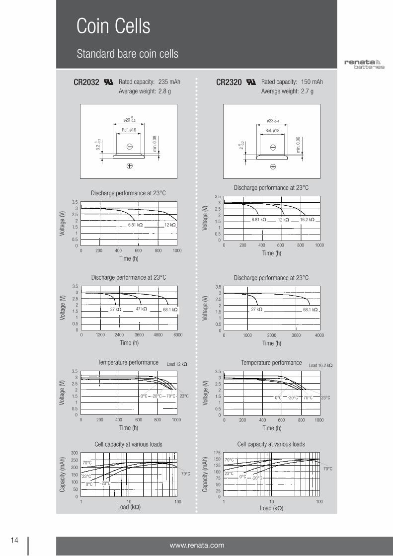
Rated capacity: 235 mAh
Average weight: 2.8 gCR2032 Rated capacity: 150 mAh
Average weight: 2.7 gCR2320
Volta
ge (V
)
Time (h)
Discharge performance at 23°C
0 200 400 600 800 1000
12 k6.81 k
3.53
2.52
1.51
0.50
Volta
ge (V
)
Time (h)
Temperature performance
0 200 400 600 800 1000
3.53
2.52
1.51
0.50
Capa
city
(mAh
)
Load (k)
Cell capacity at various loads
1 10 100
300
250
200
150
100
50
0
Volta
ge (V
)
Time (h)
Discharge performance at 23°C
0 1200 2400 3600 4800 6000
47 k 68.1 k27 k
3.53
2.52
1.51
0.50
23°C
Load 12 k
70°C0°C -20°C
23°C
70°C
70°C
0°C -20°C
ø20 0-0.3
3.2
0 -0.3
min
. 0.0
8
Ref. ø16
Volta
ge (V
)
Time (h)
Discharge performance at 23°C
0 200 400 600 800 1000
16.2 k12 k
3.53
2.52
1.51
0.50
Volta
ge (V
)
Time (h)
Temperature performance
0 200 400 600 800 1000
23°C
Load 16.2 k
70°C-20°C0°C
3.53
2.52
1.51
0.50
Capa
city
(mAh
)
Load (k)
Cell capacity at various loads
1 10 100
1751501251007550250
Volta
ge (V
)
Time (h)
Discharge performance at 23°C
0 1000 2000 3000 4000
68.1 k27 k
3.53
2.52
1.51
0.50
6.81 k
70°C
70°C
23°C0°C -20°C
ø23 0-0.4
2 0 -0
.2
min
. 0.0
6
Ref. ø18

15the swiss power source
Rated capacity: 190 mAh
Average weight: 3.0 gCR2325
Volta
ge (V
)
Time (h)
Discharge performance at 23°C
0 200 400 600 800 1000
8.25 k 12 k
3.53
2.52
1.51
0.50
Volta
ge (V
)
Time (h)
Temperature performance
0 200 400 600 800 1000
3.53
2.52
1.51
0.50
Capa
city
(mAh
)
Load (k)
Cell capacity at various loads
1 10 100
210190170150130110
9070
Volta
ge (V
)
Time (h)
Discharge performance at 23°C
0 1000 2000 3000 4000
47 k
6.81 k
27 k
3.53
2.52
1.51
0.50
70°C
23°C
Load 12 k
70°C0°C -20°C
23°C
70°C
0°C -20°C
ø23 0-0.4
2.5
0 -0.3
min
. 0.0
8
Ref. ø19
Volta
ge (V
)
Time (h)
Discharge performance at 23°C
0 200 400 600 800 1000
6.81 k5.62 k
3.53
2.52
1.51
0.50
Volta
ge (V
)
Time (h)
Temperature performance
0 250 500 750 1000 1250
23°C
Load 12 k
70°C-20°C0°C
3.53
2.52
1.51
0.50
Capa
city
(mAh
)
Load (k)
Cell capacity at various loads
1 10 100
300
275
250
225
200
175
150
Volta
ge (V
)
Time (h)
Discharge performance at 23°C
0 500 1000 1500 2000 2500 3000
27 kΩ12 kΩ
3.53
2.52
1.51
0.50
70°C
23°C0°C
-20°C
70°C
ø24.5 0-0.3
3 0 -0
.3
min
. 0.0
8
Ref. ø20
2.7 k
Rated capacity: 285 mAh
Average weight: 4.1 gCR2430

Standard bare coin cells
Coin Cells
16www.renata.com
Rated capacity: 540 mAh
Average weight: 5.9 gCR2450N Rated capacity: 950 mAh
Average weight: 8.2 g
*CR2477N
Volta
ge (V
)
Time (h)
Discharge performance at 23°C
0 200 400 600 800 1000
3.32 k2.7 k
3.53
2.52
1.51
0.50
Volta
ge (V
)
Time (h)
Temperature performance
0 300 600 900 1200 1500
3.53
2.52
1.51
0.50
Capa
city
(mAh
)
Load (k)
Cell capacity at various loads
1 10 100
600550500450400350300250
Volta
ge (V
)
Time (h)
Discharge performance at 23°C
0 1000 2000 3000 4000 5000 6000
12 k 27 k6.81 k
3.53
2.52
1.51
0.50
23°C
Load 6.81 k
70°C0°C -20°C
23°C
70°C
70°C0°C -20°C
ø24.5 0-0.3
5 0 -0
.4
2.5
Ref. ø22.3
Volta
ge (V
)
Time (h)
Discharge performance at 23°C
0 400 800 1200 1600 2000
4.7 k
3.53
2.52
1.51
0.50
Volta
ge (V
)
Time (h)
Temperature performance
0 400 800 1200 1600 2000
3.53
2.52
1.51
0.50
Capa
city
(mAh
)
Load (k)
Cell capacity at various loads
1 10 100
11501000850700550400250100
Volta
ge (V
)
Time (h)
Discharge performance at 23°C
0 1000 2000 3000 4000 5000 6000
16.2 k6.81 k
2.67 k
12 k
3.53
2.52
1.51
0.50
70°C
23°C
Load 4.7 k
70°C0°C -20°C
23°C
70°C
0°C-20°C
ø24.5 0-0.3
7.7 0 -0
.4
5.3
Ref. ø22.4
* Battery ist not userreplaceable
17the swiss power source
High temperature coin cells
Coin Cells
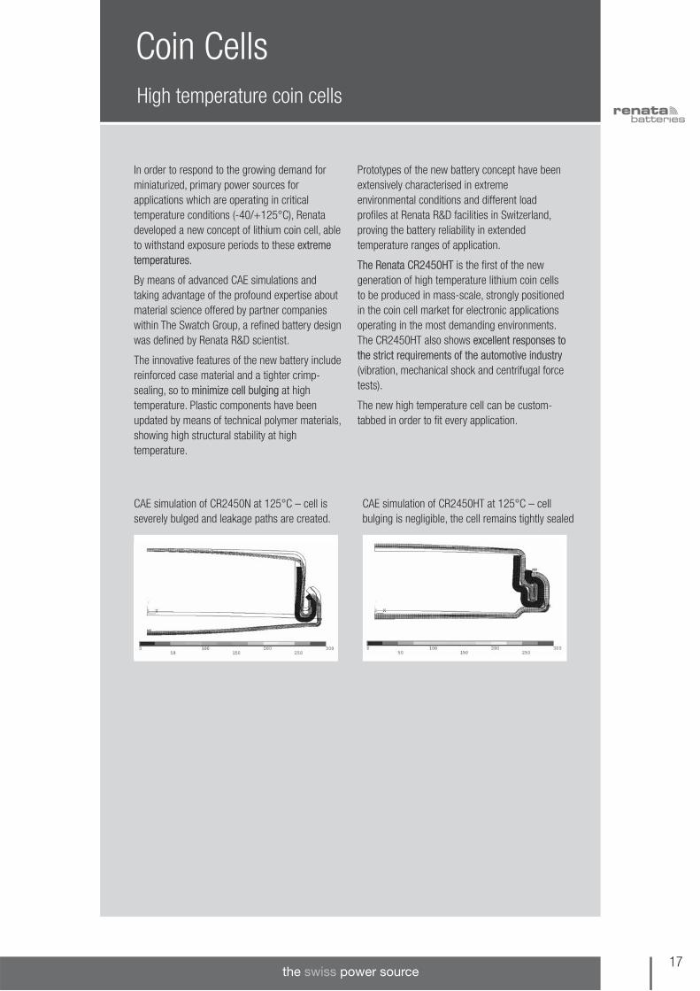
In order to respond to the growing demand forminiaturized, primary power sources forapplications which are operating in criticaltemperature conditions (-40/+125°C), Renatadeveloped a new concept of lithium coin cell, ableto withstand exposure periods to these extremetemperatures.
By means of advanced CAE simulations andtaking advantage of the profound expertise aboutmaterial science offered by partner companieswithin The Swatch Group, a refined battery designwas defined by Renata R&D scientist.
The innovative features of the new battery includereinforced case material and a tighter crimp-sealing, so to minimize cell bulging at hightemperature. Plastic components have beenupdated by means of technical polymer materials, showing high structural stability at hightemperature.
Prototypes of the new battery concept have beenextensively characterised in extremeenvironmental conditions and different loadprofiles at Renata R&D facilities in Switzerland,proving the battery reliability in extendedtemperature ranges of application.
The Renata CR2450HT is the first of the newgeneration of high temperature lithium coin cellsto be produced in mass-scale, strongly positionedin the coin cell market for electronic applicationsoperating in the most demanding environments.The CR2450HT also shows excellent responses tothe strict requirements of the automotive industry(vibration, mechanical shock and centrifugal forcetests).
The new high temperature cell can be custom-tabbed in order to fit every application.
CAE simulation of CR2450N at 125°C – cell isseverely bulged and leakage paths are created.
CAE simulation of CR2450HT at 125°C – cellbulging is negligible, the cell remains tightly sealed
1) Standard discharge current: 100% of nominalcapacity is obtained bydischarging the cells atthis current rates.
2) The maximum current isdetermined for a yield of70% of the nominal capacity with a cut-offvoltage of 2.0V, at 23°C.For currents exceedingthose given above or pulsed current, pleasecontact Renata.
High temperature coin cells
Coin Cells
Model Dimensions (mm) Weight Part. No.*A B C D (g)
CR2450HT 24.5 5.0 21.0 1.3 6.7 701700
18www.renata.com
General characteristics • Electrochemical system Li/MnO2• Operating temperature range: -40/+125°C• Storage temperature up to 100°C• Self-discharge: less than 1% per year at 23°C
• Shelf life: up to 10 years at max. 23°C• Stable voltage during shelf life• Superior leakage resistance• Contains no heavy metals
ø A 0– 0.3
ø 21
ø C + 0.1– 0.2
B0
– 0.
3
± 0.1
± 0
.1D
± 0
.10.
4
Dimensions and weights
Electrical characteristics
3.0
2.0
1.0
200 400 6000
Discharge time (hrs.)
Volta
ge (V
)
Characteristic curve at 23°C
Load 3.32 k2.00 k
1.2
1.6
0.8
0.4
4020 60 800
time in hours
heig
ht in
crea
se (m
m) comparison height increase at 120°C
CR2450
CR2450HT
100
60
20
200 400 600 800 10000
storage time (hrs.)
reco
vere
d ca
paci
ty (%
of R
C) recovered capacity1 after storage at high temp.
100°C85°C
CR2450HT
Model Nominal capacity Standard 1) Max. continuous Operatingdischarge current discharge current 2) Temperature
(mAh) (mA) (mA) (C)
CR2450HT 490 0.8 3.0 -40/+125°
*Packaging: Industrial Bulk (IB-Trays)
19the swiss power source
Packaging options
Coin Cells
Coin cells can be supplied in different packaging
1 Example: The Renata PartName of CR2032 coin cells in industrial bulk packaging is “CR2032.IB”.
2 Example: The Renata PartName of singly packagedCR1616 coin cells in cardunits is “CR1616.CU”.
Singly packaged coin cells in blistered Card Units
Five coin cells packaged in blistered Tear Strips
Industrial Bulk multi-cell plastic trays
Packaging Code: CU2
Packaging Code: TS
Card Unit packaging is e.g. used in replacement and retail business. There is one coin cell in a CardUnit, ten Card Units in a small box and ten small boxes in a bigger box.
Packaging Code: IB1
Industrial Bulk packaging is the standard packaging formanufacturers.
The number of coin cells per plastic tray depends on the respectivemodel. So does the number of plastic trays per shrink pack.
Tear Strip packaging is e.g. used inretail or DIY stores. There are fivecoin cells in a Tear Strip, four TearStrips in a small box and five smallboxes in a bigger box.
Blistered multi-cell Bulk TrayPackaging Code: BT
Bulk Tray packaging is e.g. used by small internet or cataloguedistributors. The number of coin cells per Bulk Tray depends on therespective model. So does the number of plastic trays per cardboardbox.

Two pins horizontal mounting
Coin Cells with Tabs
20www.renata.com
Catalogue of two-pins standard tabbed coin cellsfor horizontal mounting on PCBs.
Features• Excellent solderability thanks to solder-plated
areas• Suitable for wave-soldering
Specifications• Solder contacts stainless steel AISI 301,
thickness 0.15 mm• Tin-plated solder area lead free (>99.9% Sn)
plated throughout, thick ness min. 5 µm.Solderability according to MIL-STD 883C,method 2003.3
Model Nominal Max. Dimensions (mm) Weight Part.No.*Capacity(mAh) A B C D E (g)
CR1216FH-LF 25 12.50 12.70 11.00 2.40 6.30 0.9 701062CR1220FH-LF 38 12.50 12.70 11.00 2.80 6.70 1.0 701063CR1225FH-LF 48 12.50 12.70 11.00 3.30 7.20 1.1 701065CR1616FH-LF 50 16.00 16.20 12.70 2.40 6.30 1.3 701382CR1620FH-LF 68 16.00 16.20 12.70 2.80 6.70 1.4 701067CR1632FH-LF 125 16.00 16.20 11.00 3.90 7.80 2.0 701069CR1632FH1-LF 125 16.00 16.20 15.20 3.90 7.80 2.0 701070CR2016FH MFR 90 20.00 20.20 15.20 2.40 6.30 1.9 701591CR2016FH-LF 80 20.00 20.20 15.20 2.40 6.30 1.9 701072CR2016FH1 MFR 90 20.00 20.35 20.40 2.40 6.30 1.9 701593CR2016FH1-LF 80 20.00 20.35 20.40 2.40 6.30 1.9 701239CR2025FH MFR 165 20.00 20.20 15.20 3.30 7.20 2.7 701595CR2025FH-LF 170 20.00 20.20 15.20 3.30 7.20 2.5 701073CR2025FH1 MFR 165 20.00 20.20 20.40 3.30 7.20 2.7 701596CR2025FH1-LF 170 20.00 20.20 20.40 3.30 7.20 2.5 701074CR2032FH MFR 225 20.00 20.20 15.20 3.90 7.80 3.0 701599CR2032FH-LF 235 20.00 20.20 15.20 3.90 7.80 3.0 701077CR2032FH0 MFR 225 20.00 20.20 10.35 3.90 7.80 3.0 701600CR2032FH0-LF 235 20.00 20.20 10.35 3.90 7.80 3.0 701390CR2032FH1 MFR 225 20.00 20.20 20.40 3.90 7.80 3.0 701601CR2032FH1-LF 235 20.00 20.20 20.40 3.90 7.80 3.0 701078CR2032FH2 MFR 225 20.00 20.20 22.50 3.90 7.80 3.0 701603CR2032FH2-LF 235 20.00 20.20 22.50 3.90 7.80 3.0 701237CR2325FH-LF 190 23.00 23.20 20.40 3.30 7.20 3.2 701085CR2430FH-LF 285 24.50 24.70 20.40 3.90 7.80 4.3 701089CR2430FH1-LF 285 24.50 24.70 15.20 3.90 7.80 4.3 701090CR2450NFH-LF 540 24.50 24.70 20.40 5.80 9.70 6.1 701095CR2477NFH-LF 950 24.50 24.70 20.40 8.50 12.40 8.4 701100
*Packaging: Industrial Bulk (IB-Trays)

21the swiss power source
Three pins horizontal mounting
Coin Cells with Tabs
Catalogue of three-pins standard tabbed coincells for horizontal mounting on PCBs.
Features• Excellent solderability thanks to solder-plated
areas• Suitable for wave-soldering
Specifications• Solder contacts stainless steel AISI 301,
thickness 0.15 mm• Tin-plated solder area plated throughout,
thickness min. 5 µm. Solderability according toMIL-STD 883C, method 2003.3
Model Nominal Max. Dimensions (mm) Weight Part.No.*Capacity(mAh) A B C D E (g)
CR1632RH-LF 125 16.00 16.35 15.20 5.45 9.45 2.0 701238CR2016RH MFR 90 20.00 20.20 15.20 3.95 7.95 2.0 701594CR2016RH-LF 80 20.00 20.20 15.20 3.95 7.95 2.0 701380CR2025RH MFR 165 20.00 20.20 15.20 4.85 8.85 2.6 701597CR2025RH-LF 170 20.00 20.20 15.20 4.85 8.85 2.6 701075CR2032RH MFR 225 20.00 20.20 15.20 5.45 9.45 3.1 701604CR2032RH-LF 235 20.00 20.20 15.20 5.45 9.45 3.1 701080CR2032RH1 MFR 225 20.00 20.20 17.80 5.45 9.45 3.1 701605CR2032RH1-LF 235 20.00 20.20 17.80 5.45 9.45 3.1 701081CR2032RH2 MFR 225 20.00 20.35 20.40 5.45 9.45 3.0 701724CR2032RH2-LF 235 20.00 20.35 20.40 5.45 9.45 3.0 701082CR2325RH-LF 190 23.00 23.20 17.80 4.85 8.85 3.3 701087CR2430RH-LF 285 24.50 24.70 17.80 5.45 9.45 4.4 701092CR2430RH1-LF 285 24.50 24.70 20.40 5.45 9.45 4.4 701093CR2450NRH-LF 540 24.50 24.70 17.80 7.35 11.35 6.2 701097CR2450NRH1-LF 540 24.50 24.70 20.40 7.35 11.35 6.2 701098CR2477NRH-LF 950 24.50 24.70 17.80 10.05 14.05 8.5 701103
*Packaging: Industrial Bulk (IB-Trays)

Coin Cells with TabsTwo pins vertical mounting
Catalogue of two-pins standard tabbed coin cellsfor vertical mounting on PCBs.
Features• Excellent solderability thanks to solder-plated
areas• Suitable for wave-soldering
Specifications• Solder contacts stainless steel AISI 301,
thickness 0.15 mm• Tin-plated solder area plated throughout,
thickness min. 5 µm. Solderability according toMIL-STD 883C, method 2003.3
22www.renata.com
Model Nominal Max. Dimensions (mm) Weight Part.No.*Capacity(mAh)l A B C D E (g)
CR1025FV-LF 30 10.00 2.50 2.80 11.00 5.08 0.8 701060CR1025FV1-LF1) 30 10.00 2.50 2.80 11.00 5.08 0.8 701064CR1216FV-LF 25 12.50 1.60 1.90 13.60 5.08 0.9 701370CR1220FV-LF 38 12.50 2.00 2.30 13.50 5.08 1.0 701061CR1225FV-LF 48 12.50 2.50 2.80 13.50 5.08 1.1 701066CR1616FV-LF 50 16.00 1.60 1.90 17.00 5.08 1.3 701381CR1620FV-LF 68 16.00 2.00 2.30 17.00 5.08 1.4 701068CR1632FV-LF 125 16.00 3.20 3.50 17.00 5.08 2.0 701071CR2016FV MFR 90 20.00 1.60 1.60 21.10 10.50 2.0 701426CR2016FV-LF 80 20.00 1.60 1.60 21.10 10.50 2.0 701725CR2032FV MFR 225 20.00 3.20 3.50 21.00 10.50 3.0 701606CR2032FV-LF 235 20.00 3.20 3.50 21.00 10.50 3.0 701079CR2320FV-LF 150 23.00 2.00 2.30 24.00 10.50 2.9 701084CR2325FV-LF 190 23.00 2.50 2.80 24.00 10.50 3.2 701086CR2430FV-LF 285 24.50 3.00 3.30 25.50 10.50 4.3 701091CR2450NFV-LF 540 24.50 5.00 5.80 25.50 10.50 6.1 701096CR2477NFV-LF 950 24.50 7.70 8.00 25.50 10.50 8.4 701101
*Packaging: Industrial Bulk (IB-Trays)
1 CR1025FV1-LF has thesame dimensions asCR1025FV-LF but reversepolarity.
23the swiss power source
Three pins vertical mounting
Coin Cells with Tabs
Catalogue of three-pins standard tabbed coincells for vertical mounting on PCBs.
Features• Excellent solderability thanks to solder-plated
areas• Suitable for wave-soldering
Specifications• Solder contacts stainless steel AISI 301,
thickness 0.15 mm• Tin-plated solder area plated throughout,
thickness min. 5 µm. Solderability according toMIL-STD 883C, method 2003.3
Model Nominal Max. Dimensions (mm) Weight Part.No.*Capacity(mAh) A B C D (g)
CR2025RV MFR 165 20.00 2.50 2.80 21.00 2.8 701598CR2025RV-LF 170 20.00 2.50 2.80 21.00 2.6 701076CR2032RV MFR 225 20.00 3.20 3.50 21.00 3.1 701607CR2032RV-LF 235 20.00 3.20 3.50 21.00 3.1 701083CR2325RV-LF 190 23.00 2.50 2.80 24.00 3.3 701088CR2430RV-LF 285 24.50 3.00 3.30 25.50 4.4 701094CR2450NRV-LF 540 24.50 5.00 5.30 25.50 6.2 701099CR2477NRV-LF 950 24.50 7.70 8.00 25.50 8.5 701104
*Packaging: Industrial Bulk (IB-Trays)
Isotan1) tabs for through-hole mounting
Coin Cells with Tabs
24www.renata.com
Catalogue of two-pins, Isotan1)-tabbed coin cellsfor horizontal mounting on PCBs.
Features• Good solderability• Suitable for wave-soldering
Specifications• Tab material: Isotan (54% Cu, 44% Ni, Mn)
Model Nominal Dimensions (mm) Weight Part.No.*Capacity(mAh) A B C D E (g)
CR1225AH 48 12.50 13.3 11.0 3.10 7.6 1.1 700772
CR1632AH1 125 16.00 17.0 15.2 3.80 7.6 2.0 700534
CR2025AH MFR 165 20.00 21.0 15.2 3.10 7.6 2.7 701720
CR2025AH 170 20.00 21.0 15.2 3.10 7.6 2.5 700310
CR2032AH MFR 225 20.00 21.0 15.2 3.85 7.6 3.0 701721
CR2032AH 235 20.00 21.0 15.2 3.85 7.6 3.0 700771
CR2032AH0 MFR 225 20.00 21.0 10.35 3.85 7.6 3.0 701722
CR2032AH0 235 20.00 21.0 10.35 3.85 7.6 3.0 700324
CR2032AH1 MFR 225 20.00 21.0 20.4 3.85 7.6 3.0 701723
CR2032AH1 235 20.00 21.0 20.4 3.85 7.6 3.0 700325
CR2430AH 285 24.50 25.3 20.4 3.60 7.6 4.3 700360
CR2450NAH 540 24.50 25.3 20.4 5.60 5.6 6.1 700378
CR2477NAH 950 24.50 25.3 20.4 8.30 3 8.3 700393
ø A
B ±0.3
0 -0.3
C
1 m
in.
layout top viewlayout sideviewfrom below
E11.2
±0.
3
D±
0.3
±0.
3
*Packaging: Industrial Bulk (IB-Trays)
1) Isotan® is a registeredtrademark ofIsabellenhütte HeuslerGmbH & Co. KG.

25the swiss power source
Isotan1) tabs for surface-mounting
Coin Cells with Tabs
Catalogue of SM-tabbed coin cells for horizontalmounting on PCBs.
Features• Good solderability, but not suitable for
reflow-soldering
Specifications• Tab material: Isotan (54% Cu, 44% Ni, Mn)
ø A
B+0.3
0
+0
–0.1
C ±0.5 G+0.3–0
3.0
F±
0.3
E+
0.2
–0.3
D ±0.3
Top view side view layout top view
zone for soldering
3
1) Isotan® is a registeredtrademark ofIsabellenhütte HeuslerGmbH & Co. KG.
2) Customized SM-Tabconfiguration uponrequest – seeCustomized BatterySolutions
Model Nominal Dimensions (mm) Part.No.*Capacity(mAh) A B C D E F G
CR1025SM 30 10.0 +0/-0,3 13.0 16.0 2.0 2.8 6.5 14.0 701960
CR1216SM 25 12.5 +0/-0,3 15.75 19.0 2.0 1.9 7.75 17.0 701961
CR1220SM 38 12.5 +0/-0,3 15.75 19.0 2.0 2.3 7.75 17.0 701962
CR1225SM 48 12.5 +0/-0,3 15.75 19.0 2.0 2.8 7.75 17.0 701964
CR1616SM 50 16.0 +0/-0,3 20.0 24.0 3.0 1.9 9.5 21.0 701965
CR1620SM 68 16.0 +0/-0,3 20.0 24.0 3.0 2.3 9.5 21.0 701966
CR1632SM 125 16.0 +0/-0,3 20.0 24.0 3.0 3.5 9.5 21.0 701967
CR2016SM MFR 90 20.0 +0/-0,3 24.0 28.0 3.0 1.9 11.5 25.0 701969
CR2016SM 80 20.0 +0/-0,3 24.0 28.0 3.0 1.9 11.5 25.0 701968
CR2025SM MFR 165 20.0 +0/-0,3 24.0 28.0 3.0 2.8 11.5 25.0 701971
CR2025SM 170 20.0 +0/-0,3 24.0 28.0 3.0 2.8 11.5 25.0 701970
CR2032SM MFR 225 20.0 +0/-0,3 24.0 28.0 3.0 3.5 11.5 25.0 701973
CR2032SM 235 20.0 +0/-0,3 24.0 28.0 3.0 3.5 11.5 25.0 701972
CR2320SM 150 23.0 +0/-0,4 28.0 33.0 4.0 2.3 13.0 29.0 701974
CR2325SM 190 23.0 +0/-0,4 28.0 33.0 4.0 2.8 13.0 29.0 701975
CR2430SM 285 24.5 +0/-0,3 29.5 34.5 4.0 3.3 13.75 30.5 701976
CR2450SM 540 24.5 +0/-0,3 29.5 34.5 4.0 5.3 13.75 30.5 701977
CR2477SM 950 24.5 +0/-0,3 29.5 34.5 4.0 8.0 13.75 30.5 701978
*Packaging: Industrial Bulk (IB-Trays)
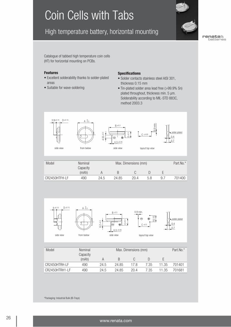
High temperature battery, horizontal mounting
Coin Cells with Tabs
26www.renata.com
Catalogue of tabbed high temperature coin cells(HT) for horizontal mounting on PCBs.
Features• Excellent solderability thanks to solder-plated
areas• Suitable for wave-soldering
Specifications• Solder contacts stainless steel AISI 301,
thickness 0.15 mm• Tin-plated solder area lead free (>99.9% Sn)
plated throughout, thick ness min. 5 µm.Solderability according to MIL-STD 883C,method 2003.3
layout top viewside view side viewfrom below
A 0- 0.3
±0.05C
0.9
min
.
D±0.15±0.153.9
0.4
0.7
solder plated
B
0.3
E
4.55
±0.3
±0.05
±0.
3
±0.
3
*Packaging: Industrial Bulk (IB-Trays)
Model Nominal Max. Dimensions (mm) Part.No.*Capacity(mAh) A B C D E
CR2450HTRH-LF 490 24.5 24.85 17.8 7.35 11.35 701401CR2450HTRH1-LF 490 24.5 24.85 20.4 7.35 11.35 701681
Model Nominal Max. Dimensions (mm) Part.No.*Capacity(mAh) A B C D E
CR2450HTFH-LF 490 24.5 24.85 20.4 5.8 9.7 701400
±0.5C
10.1
5
layout top viewside view side viewfrom below
0.4
0.7
0.9 min.
E
6.2
±0.
3
±0.
3
B ±0.3
A 0- 0.3D±0.15
solder plated
4 ±0.15
0.3 ±0.05
27the swiss power source
High temperature battery, vertical mounting
Coin Cells with Tabs
Catalogue of tabbed high temperature coin cells(HT) for vertical mounting on PCBs.
Features• Excellent solderability thanks to solder-plated
areas• Suitable for wave-soldering
Specifications• Solder contacts stainless steel AISI 301,
thickness 0.15 mm• Tin-plated solder area lead free (>99.9% Sn)
plated throughout, thick ness min. 5 µm.Solderability according to MIL-STD 883C,method 2003.3
*Packaging: Industrial Bulk (IB-Trays)
Model Nominal Max. Dimensions (mm) Part.No.*Capacity(mAh) A B C D E
CR2450HTFV-LF 490 24.5 5.0 5.3 25.6 10.5 701950
Model Nominal Max. Dimensions (mm) Part.No.*Capacity(mAh) A B C D E
CR2450HTRV-LF 490 24.5 5.0 5.3 25.5 10.15 701951
layout top view
0.4
0.7
B 0- 0.4 A
0- 0.3
solder plated
E
0.9
min
.
CD±
0.3
3.9
±0.
15
side view
0.3
C
±0.05
+0.1–0.4
minus side view plus side view
layout top viewside view
B 0- 0.4
0.4
0.7
A 0- 0.3
solder plated
D±
0.3
4±
0.15
E
0.9
min
.
C
0.3
C
±0.05
+0.1–0.4
minus side view plus side view

Packaging options
Coin Cells with Tabs
28www.renata.com
All tabbed coin cells are supplied in the following packaging:
Packaging Code: IB
Industrial Bulk multi-cell plastic trays
Industrial Bulk packaging is the standardpackaging for manufacturers.
The number of tabbed coin cells per plastic traydepends on the respective model. So does thenumber of plastic trays per shrink pack.

29the swiss power source
Notes

Surface Mounting Technology (SMT)
Battery Holders
30www.renata.com
Horizontal mounting
Features• Easy and fast replacement of the battery• Designed for automatic pick&place mounting• Safe retention of coin cell• Automated battery mounting possible• Clear separation of connections• Protection against short-circuits• Protection against inverse polarity (polarized)• Protection against leak currents• Robust design• Suitable for reflow-soldering
Specifications• Holder material: heat-resistant, glass fibre
filled LCP• Flammability rating UL 94 V-0• Battery contacts: spring stainless steel AISI 301,
nickel-plated throughout, thickness 10 µm.Solder area tin-plated throughout, thickness 10 µm.
• Contact resistance between contacts and thecell is less than 100 m (measured throughAC 1kHz; depending on the case material ofthe cell).
• UL recognition, file E218732• Operating temperature range: –40/+100°C
Model For use with Dimensions (mm) Weight Part.No.*Renata cell A B C D E F (g)
SMTU357-LF 357 (SR44W) 23.3 19.9 11.6 12.0 7.55 20.7 0.85 701132SMTU1220-LF CR1220 23.7 20.3 12.5 12.7 4.8 21.1 0.80 701114SMTU1225-LF CR1225 23.7 20.3 12.5 12.7 4.8 21.1 0.70 701115SMTU1632-LF CR1632 27.7 24.3 16.0 14.5 5.4 25.1 0.80 701130SMTU2032-LF CR2032 32.0 28.5 20.0 16.1 5.4 29.4 0.95 701116SMTU2430-LF CR2430 36.4 33.0 24.5 16.1 4.9 33.8 1.05 701117SMTU2450N-LF CR2450N1) 36.4 33.0 24.5 16.1 7.5 33.8 1.45 701118SMTU2477N-LF CR2477N 36.4 33.0 24.5 16.1 10.3 33.8 1.65 701119SM2X2016-LF CR2016 32.0 28.5 20.0 16.1 5.4 29.4 0.95 701113
Dimensions
*Packaging: Industrial Bulk (IB-Trays)
1) Not suitable forCR2450HT

31the swiss power source
Through-hole mounting
Battery Holders
Horizontal mounting
Features• Easy and fast replacement of the battery• Designed for automatic pick&place mounting• Safe retention of coin cell• Automated battery mounting possible• Clear separation of connections• Protection against short-circuits• Protection against inverse polarity (polarized)• Protection against leak currents• Robust design• Suitable for wave-soldering
Specifications• Holder material: heat-resistant, glass fibre
filled LCP• Flammability rating UL 94 V-0• Battery contacts: spring stainless steel AISI 301,
nickel-plated throughout, thickness 10 µm.Solder area tin-plated throughout, thickness 10 µm.
• Contact resistance between contacts and thecell is less than 100 m (measured through AC 1kHz; depending on the case material of thecell).
• UL recognition, file E218732• Operating temperature range: –40/+100°C
±0.3
Model For use with Dimensions (mm) Weight Part.No.*Renata cell B C D E F (g)
HU357-LF 357 (SR44W) 19.9 11.6 12.0 7.4 18.15 0.84 701133HU1225-LF CR1225 20.3 12.5 12.7 4.5 18.7 0.70 701105HU1632-LF CR1632 24.3 16.0 14.5 5.2 22.7 0.80 701131HU2032-LF CR2032 28.5 20.0 16.1 5.2 26.9 0.95 701106HU2430-LF CR2430 33.0 24.5 16.1 4.7 31.5 1.05 701107HU2450N-LF CR2450N1) 33.0 24.5 16.1 7.3 31.5 1.45 701108HU2477N-LF CR2477N 33.0 24.5 16.1 10.1 31.5 1.65 701109
Dimensions
*Packaging: Industrial Bulk (IB-Trays)
1) Not suitable forCR2450HT

Through-hole mounting
Battery Holders
Vertical mounting
VBH2032-1 - Vertical battery holder for Renata coin cell CR2032
32www.renata.com
Features• Small PCB footprint• Easy and fast replacement of the battery• Safe retention of coin cell• Protection against short-circuits• Protection against inverse polarity (polarized)• Protection against leak currents• Robust design• Suitable for wave-soldering
Specifications• Holder material: polyamide• Flammability rating UL 94 V-0• Battery contacts: spring stainless steel AISI 301,
nickel-plated throughout, thickness 5 µm min. • Solder area tin-plated throughout, thickness
10 µm• UL recognition, file E218732• Operating temperature range: -40/+85°C
*Packaging: Industrial Bulk (IB-Trays)
Model For use with Renata cell Weight (g) Part. No.*
VBH2032-1 CR2032 1.6 700579
Dimensions (mm)

33the swiss power source
Through-hole mounting with positioning pins
Battery Holders
Battery holders for CR2450N or CR2477NVertical and horizontal versions
Features• Easy and fast replacement of the battery• Snap-on fixing for coin cells• Safe retention of coin cell• Automated battery mounting possible• Clear separation of connections• Protection against short-circuits• Protection against inverse polarity• Protection against leak currents• Robust design• Easy and safe PCB mounting due to additional
positioning pins• Suitable for wave-soldering
Specifications• Holder material: polyamide• Flammability rating UL 94 V-2• Battery contacts: Nickel 99.6 DIN 17740• Contact resistance between contacts and the
cell is less than 100 m (measured through AC 1kHz).
• Solder and positioning pins tin plated through-out (plating thickness min. 5 µm)
• UL recognition, file E218732• Operating temperature range: –40/+85°C
NH5077-LF Vertical version
NL5077-LF Horizontal version
Model For use with Weight Part.No.*Renata cell (g)
NH5077-LF CR2450N1), CR2477N 2.4 701111
NL5077-LF CR2450N1), CR2477N 2.9 701112
*Packaging: Industrial Bulk (IB-Trays)
1) Not suitable forCR2450HT

Packaging options
Battery Holders
Battery holders can be supplied in different packaging
34www.renata.com
Industrial Bulk multi-cell traysPackaging Code: IB
Industrial Bulk packaging is the standardpackaging for manufacturers.
The number of battery holders per tray dependson the respective model. So does the number oftrays per shrink pack.
Tape&Reel packaging
For SMT-battery holders there is a Tape&Reelpackaging solution available.
Tape&Reel packaging is ideal for high-speed,automated manufacturing lines.
The number of battery holders per reel depends onthe respective model.
Packaging Code: TR
Quantity per reel:
*Packaging: Tape&Reel (TR)
Model Quantity per Reel Part.No.*
SMTU1225-LF 750 pieces 701230
SMTU1632-LF 520 pieces 701231
SMTU2032-LF 485 pieces 701232
SMTU2430-LF 490 pieces 701233
SMTU2450N-LF 350 pieces 701234
SMTU2477N-LF 250 pieces 701235
SM2X2016-LF 485 pieces 701236

35the swiss power source
Packaging options
Battery Holders
1. 10 sprocket hole pitchcumulative tolerance +/-.02
2. Camber not to exceed1mm in 100 mm
3. Material: Black ConductiveAdvantek Polystyrene
4. E measured from a planeon the inside bottom ofthe pocket to the top surface of the carrier
5. Pocket position relative tosprocket hole measuredas true position of pocket,not pocket hole
All packaging materials comply witch relevant EIA, EIAJ and IEC specifications.
Dimensions of antistatic packaging reels
Model Dimensions (mm)W max.
SMTU1225-LF 50 ±1.0
SMTU1632-LF 50 ±1.0
SMTU2032-LF 50 ±1.0
SMTU2430-LF 50 ±1.0
SMTU2450N-LF 62 ±1.0
SMTU2477N-LF 62 ±1.0
SM2x2016-LF 50 ±1.0
W max.
330.0 REF 100.0 REF
ø 13.2
120°
2.2
±0.2
±0.2
17.3
±0.
2
MATTE FINISH THESE AREAS
Dimensions of antistatic carrier tapes:
Model Dimensions (mm)A B C D E
SMTU1225-LF 44.0 40.4 16.0 20.2 5.7
SMTU1632-LF 44.0 40.4 20.0 20.2 6.1
SMTU2032-LF 44.0 40.4 24.0 20.2 6.0
SMTU2430-LF 56.0 52.4 24.0 26.2 5.7
SMTU2450N-LF 56.0 52.4 24.0 26.2 8.2
SMTU2477N-LF 56.0 52.4 24.0 26.2 10.8
SM2x2016-LF 44.0 40.4 24.0 20.2 6.0

Overview
Encapsulated Batteries (Power Modules)
36www.renata.com
Why use encapsulated batteries (Power Modules)?RENATA Power Modules were specially designedfor applications with long life expectations in adifficult environment, e.g. outdoors or under dustyor high humidity conditions. The cell ishermetically sealed in a plastic case whichprotects the sealing system of the cell itselfagainst negative external influences. In addition, itreduces the evaporation of electrolyte from thebattery as well as the diffusion of humidity fromthe environment into the cell through thepolymeric plastic gasket. An ideal solution for usein off-shore property or tropical areas.
RENATA Power Modules are available as solder orplug-in versions, with or without incorporateddecoupling diodes.
Features• Hermetically sealed• Max. protection against harsh envrionmental
conditions (hot, humid or dusty areas)• Low self-discharge• Operating and storage temperature:
-40°/+85°C1)
• Suitable for wave soldering• Free of heavy metals• Gold-plated plug-in pins for best contact
reliability
Specifications• Power Module case: Polyamide • Soldering contacts: Isotan2) (55% CU,
44% Ni, Mn)
with decoupling diodes without decoupling diodes
Model Matrix With Decoupling Diodes Without Decoupling Diodes
Horizontal mountingFor soldering 1000-1, (page 34) 175-0; 1000-0, (page 35)
For plug-in 1000-1B, (page 36) 175-0B; 1000-0B, (page 37)
Vertical mounting For soldering 175-2, (page 33) 338A, (page 34)
1) In applications wherethe Powere Modul isexposed to temperatu-res above 70°C, pleasecontact Renata for con-sultancy.
2) Isotan® is a registeredtrademark ofIsabellenhütte HeuslerGmbH & Co. KG.
1 10 1000100
Current (µA)
Volta
ge (V
OUT)
Output Voltage vs. Output Current
0.1
3.1
2.9
3.0
VIN=0
1 10 1000100
Current (µA)
Output Voltage vs. Output Current
0.1
2.9
2.7
2.5
2.3
2.8
3.0
2.6
2.4
Volta
ge (V
OUT)

37the swiss power source
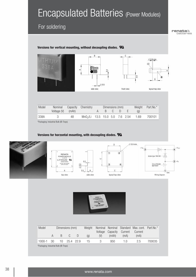
For soldering
Encapsulated Batteries (Power Modules)
Versions for vertical mounting, with decoupling diodes
Model Dimensions (mm) Weight Nominal Nominal Standard Max. cont. Part.No.*Voltage Capacity Current Current
A B C D E (g) (V) (mAh) (mA) (mA)
175-2 25 24 8.5 5.08 20.32 6.5 3 235 0.4 3.0 700044
*Packaging: Industrial Bulk (IB-Trays)
38www.renata.com
Model Dimensions (mm) Weight Nominal Nominal Standard Max. cont. Part.No.*Voltage Capacity Current Current
A B C D (g) (V) (mAh) (mA) (mA)
1000-1 30 10 25.4 22.9 15 3 950 1.0 2.5 700035*Packaging: Industrial Bulk (IB-Trays)
Versions for horzontal mounting, with decoupling diodes.
For soldering
Encapsulated Batteries (Power Modules)
Versions for vertical mounting, without decoupling diodes.
Model Nominal Capacity Chemistry Dimensions (mm) Weight Part.No.*Voltage (V) (mAh) A B C D E (g)
338A 3 48 MnO2/Li 13.5 15.0 5.0 7.6 2.54 1.69 700101
*Packaging: Industrial Bulk (IB-Trays)

39the swiss power source
For soldering
Encapsulated Batteries (Power Modules)
Versions for horzontal mounting, without decoupling diodes.
Model Dimensions Weight Nominal Nominal Standard Max. cont. Part.No.*(mm) Voltage Capacity Current Current
A B C D (g) (V) (mAh) (mA) (mA)
175-0 22 8 17.8 2.1 6.5 3 235 0.4 3.0 700040
1000-0 30 10 25.4 2.3 15 3 950 1.0 2.5 700031
*Packaging: Industrial Bulk (IB-Trays)

40www.renata.com
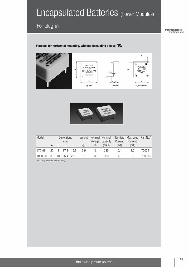
For plug-in
Encapsulated Batteries (Power Modules)
Versions for horizontal mounting, with decoupling diodes.
Model Dimensions Weight Nominal Nominal Standard Max. cont. Part.No.*(mm) Voltage Capacity Current Current
A B C D (g) (V) (mAh) (mA) (mA)
1000-1B 30 10 25.4 22.9 15 3 950 1.0 2.5 700036
*Packaging: Industrial Bulk (IB-Trays)
41the swiss power source
For plug-in
Encapsulated Batteries (Power Modules)
Versions for horizontal mounting, without decoupling diodes.
Model Dimensions Weight Nominal Nominal Standard Max. cont. Part.No.*(mm) Voltage Capacity Current Current
A B C D (g) (V) (mAh) (mA) (mA)
175-0B 22 8 17.8 15.3 6.5 3 235 0.4 3.0 700041
1000-0B 30 10 25.4 22.9 15 3 950 1.0 2.5 700033*Packaging: Industrial Bulk (IB-Trays)

Packaging options
Encapsulated Batteries (Power Modules)
42www.renata.com
All encapsulated batteries (Power Modules) are supplied in the following packaging
Industrial Bulk multi-cell trays
Packaging Code: IB
Industrial Bulk packaging is the standard packagingfor manufacturers.
The number of encapsulated batteries per traydepends on the respective model. So does thenumber of trays per shrink pack.

43the swiss power source
Optional antimagnetic case material
Customized Battery Solutions
Renata coin cells can also be supplied with antimagnetic case material (required from specialapplications like medical equipment). Some products are already available with the antima-
gnetic case (see table below). Contact Renata if you need antimagnetic versionsof other types of Renata coin cell product portfolio.
Model Nominal Nominal Standard discharge Max. cont. discharge Part.No.*voltage (V) capacity (mAh) current (mA) current (mA)
CR2032AM 3 235 0.4 3.0 701730
CR2450NAM 3 540 0.8 3.0 701740
Antimagnetic products
Apart from the standard program of lithiumtabbed coin cells, Renata offers the possibility ofcustomized solutions of tabbed coin cells.
You can get a prompt response to your designand manufacturing needs by contacting our
engineering team, especially devoted to customersupport. Feasibility study, prototyping andindustrialization are part of this solution-oriented,technical service.
Contact Renata sales network to get your ownproject!
*Packaging: Industrial Bulk (IB-Trays)
Optional tab configuration
Examples of customized solutions

44www.renata.com
Chemistry and Construction
Chemistry of RENATA Li/MnO2 cells Renata CR lithium coin cells use a non-aqueous,aprotic organic electrolyte containing lithium per-chlorate in a mixture of organic solvents. The pro-prietary formulation of the active cathode materialconsists of a heat-treated mixture of electrolyticMnO2 and other specific components, yielding anoutstanding volume/capacity ratio for this Li/MnO2
system.
The cell reactions for this electrochemical systemare:
Anode: Li –> Li+ + e-
Cathode: MnIVO2 + Li+ + e- –> MnIIIO2 (Li+)
Overall cell reaction: Li + MnIVO2 –> MnIIIO2 (Li+)
Manganese dioxide is reduced from thetetravalent to the trivalent state by lithium.
The separator system in Renata coin cells isespecially designed to ensure the bestperformance in terms of mechanical strength, ionpermeability over a wide temperature range (-40 to +100°C) and a low self-discharge rate.Additional care in cell design also minimizes self-discharge rate.
The combination of these several featuresprovides the best performance for long lifeapplications (back-up etc.)
Separator
Gasket Anode (Lithium)
Absorbent Layer and Electrolyte
Cathode (MnO2)
Cup Contact
LidContact
Separator
Gasket
Current Collector
Anode (Lithium)
Absorbent Layer and Electrolyte
Cathode (MnO2)
Cup Contact
Lid Contact
Construction of RENATA Li/MnO2 cells
45the swiss power source
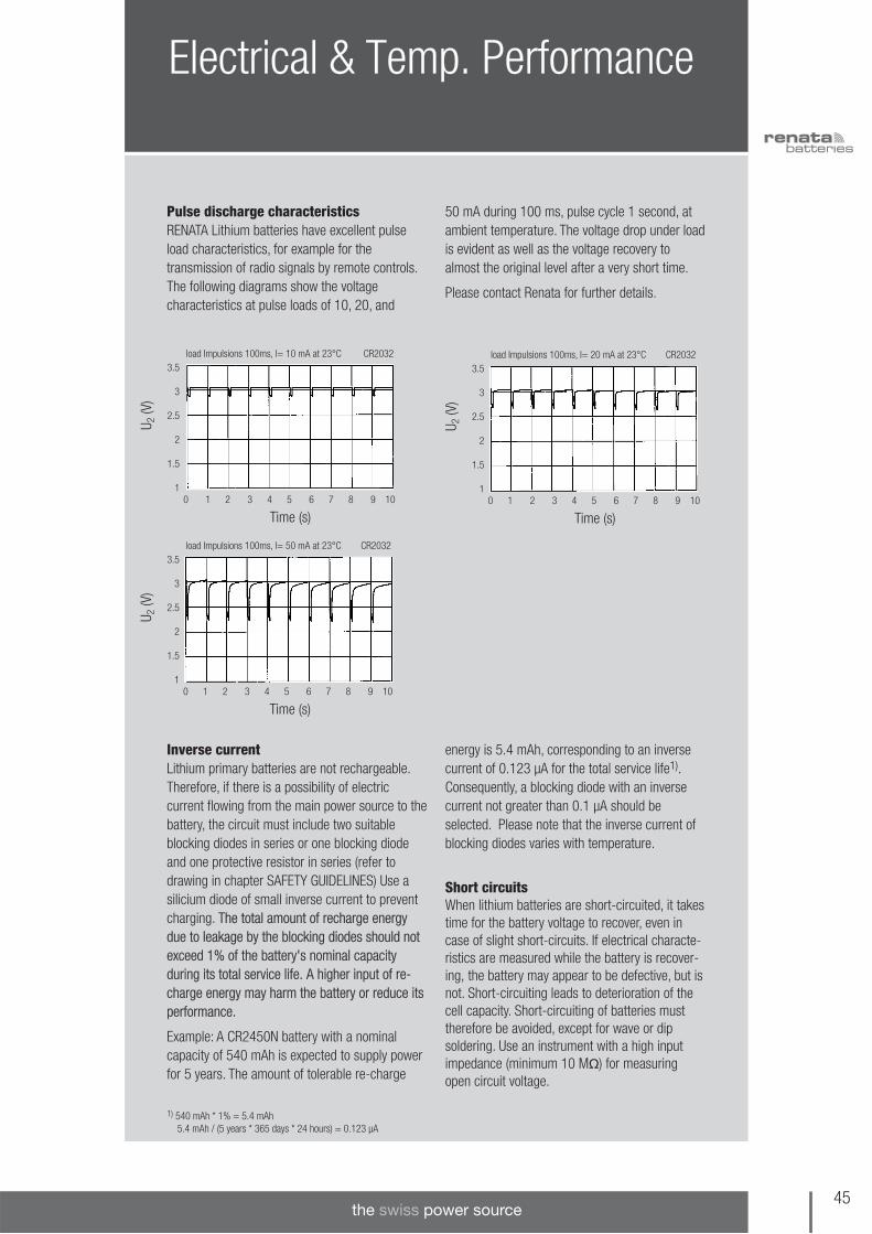
Electrical & Temp. Performance
Pulse discharge characteristicsRENATA Lithium batteries have excellent pulseload characteristics, for example for thetransmission of radio signals by remote controls.The following diagrams show the voltagecharacteristics at pulse loads of 10, 20, and
50 mA during 100 ms, pulse cycle 1 second, atambient temperature. The voltage drop under loadis evident as well as the voltage recovery toalmost the original level after a very short time.
Please contact Renata for further details.
Inverse currentLithium primary batteries are not rechargeable.Therefore, if there is a possibility of electriccurrent flowing from the main power source to thebattery, the circuit must include two suitableblocking diodes in series or one blocking diodeand one protective resistor in series (refer to drawing in chapter SAFETY GUIDELINES) Use asilicium diode of small inverse current to preventcharging. The total amount of recharge energydue to leakage by the blocking diodes should notexceed 1% of the battery's nominal capacityduring its total service life. A higher input of re-charge energy may harm the battery or reduce itsperformance.
Example: A CR2450N battery with a nominalcapacity of 540 mAh is expected to supply powerfor 5 years. The amount of tolerable re-charge
energy is 5.4 mAh, corresponding to an inversecurrent of 0.123 µA for the total service life1).Consequently, a blocking diode with an inversecurrent not greater than 0.1 µA should beselected. Please note that the inverse current ofblocking diodes varies with temperature.
Short circuitsWhen lithium batteries are short-circuited, it takestime for the battery voltage to recover, even incase of slight short-circuits. If electrical characte-ristics are measured while the battery is recover-ing, the battery may appear to be defective, but isnot. Short-circuiting leads to deterioration of thecell capacity. Short-circuiting of batteries musttherefore be avoided, except for wave or dip soldering. Use an instrument with a high inputimpedance (minimum 10 M) for measuringopen circuit voltage.
U 2(V
)
Time (s)
load Impulsions 100ms, l= 10 mA at 23°C CR2032
0 1 2 3 4 5 6 7 8 9 10
3.5
3
2.5
2
1.5
1
U 2(V
)
Time (s)
load Impulsions 100ms, l= 20 mA at 23°C CR2032
0 1 2 3 4 5 6 7 8 9 10
3.5
3
2.5
2
1.5
1
U 2(V
)
Time (s)
load Impulsions 100ms, l= 50 mA at 23°C CR2032
0 1 2 3 4 5 6 7 8 9 10
3.5
3
2.5
2
1.5
1
1) 540 mAh * 1% = 5.4 mAh5.4 mAh / (5 years * 365 days * 24 hours) = 0.123 µA

Electrical & Temp. Performance
Superior environmental resistanceThe combination of RENATA's sealing system andthe use of organic electrolytes with low creepingtendency ensure the excellent leakage resistanceof our batteries. Each production lot is subjectedto a quality assurance program under difficultenvironmental conditions (high temperaturestorage, high temperature/high humidity storage,temperature cycling, etc.). RENATA batteries canbe operated in any physical position.
Why use RENATA Lithium Power ModulesRENATA Power Modules were specially designedfor applications with long life expectations in adifficult environment, e.g. outdoors or under dustyor high humidity conditions. The cell ishermetically sealed in a plastic case whichprotects the sealing system of the cell itselfagainst negative external influences. In addition, itreduces the evaporation of electrolyte from thebattery as well as the diffusion of humidity fromthe environment into the cell through thepolymeric plastic gasket, an ideal solution for usein tropical areas.
RENATA Power Modules are available as solder orplug-in versions, with or without incorporateddecoupling diodes.
46www.renata.com
47the swiss power source
General electrical performance
Frequently Asked Questions (FAQ)
Which values of open circuit voltage dolithium cells typically show?The CR-type coin cells, based on the lithium/manganese dioxide electrochemical system, havea nominal voltage of 3 V. In practice, a freshlithium cell will typically show an OCV (OpenCircuit Voltage) between 3.15-3.35 V. This rangeof values is intended for measurementsperformed at room temperature; in fact, the OCVvalues depend on the temperature of themeasurement.
After storage periods the cells may also showvalues outside this range, due to ageing effects(see the recommended storage conditions forlithium coin cells, also reported in this document).
What is the internal resistance of a cell?How does it affect the performance of thecell?From an electrical point of view, a cell is acombination of an energy source and aresistance. The internal resistance (Ri) is a keyparameter for a cell, as it determines its high-power capability (i.e. its ability of delivering itsenergy in a short time). The internal resistancereduces the useful voltage in applications andleads to internal heat, thus loss of energy, whichincreases with the square of the current.
The internal resistance of lithium cell is a sum ofboth ohmic contributions and of resistivecontributions coming from electrochemicalphenomena taking place during the discharge ofthe cell. By accurate selection and quality control
of materials, Renata manufacturing processminimizes the resistive factors contributing to theinternal resistance of the lithium cells.
As the internal resistance includes a number ofresistive contributions coming from electro -chemical phenomena, each of them beingcharacterised by a time constant, the value ofinternal resistance is pretty much depending fromthe measuring method and conditions. A simpleand inexpensive method for measuring the Ri is toapply a resistive load (R1) to the cell and tomeasure the value of the cell voltage under load(CCV, Closed Circuit Voltage). The internalresistance is then calculated as:
Ri = ( OCV - CCV ) x R1 / CCV.
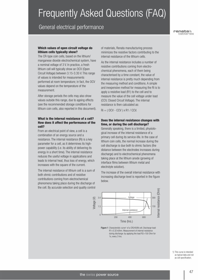
Does the internal resistance changes withtime, or during the cell discharge?Generally speaking, there is a limited, physiolo -gical increase of the internal resistance of aprimary cell during its service-life. In the case oflithium coin cells, the normal increase during thecell discharge is due both to ohmic factors (thedistance between the electrodes increases duringdischarge) and to electrochemical phenomenataking place at the lithium anode (growing ofinterface films between lithium metal andelectrolyte solution).
The increase of the overall internal resistance withincreasing discharge level is reported in the figurebelow.
3.0 300
1501.5
400200 6000
Time (hrs.)
Volta
ge (V
)
Inte
rnal
resi
stan
ce (O
hm)
Voltage
Internal resistance
Figure 1 Characteristic curve1 of a CR2450N cell. Discharge load:R1=3.32 kOhm. Measurement of internal resistanceduring discharge: by applying the load R2=150 Ohm for1s, every 3 hrs.
1) This curve is intendedas typical data and notas cell specification.

General electrical performance
Frequently Asked Questions (FAQ)
The ageing of the cells at normal conditions (i.e.room temperature, max. 40% of relative humidity)will also lead to other physiological increases ofthe internal resistance, due to normal ageingphenomena taking place at the electrodes.Though of limited extent, these types of increasesof the internal resistance are normally to beexpected and must be also taken into account,when designing a new application.
Exposing the cells to elevated temperatures, then,can lead to further grow of the passivation films atthe anode, with an additional increase of internalresistance. Furthermore, increasing thetemperature above 70°C can cause the internalresistance to abnormally increase (because ofelectrolyte leakages and degradationphenomena). Abuse conditions such as dischargeat elevated currents and short-circuit can alsoincrease the internal resistance abnormally,because of the deterioration of cell internalcomponents.
Which is the voltage drop of the lithiumcell during current pulse? The voltage drop during a current pulse (V) isthe difference between the cell voltage just beforeapplying the pulse (Voltage-high, V1) and the cellvoltage during the pulse (Voltage-low, V2):
V = V2 - V1
It is also expressed by the formula:
V = Ri x Ipeak,
where Ri (internal resistance) depends on the celltype and dimensions. In addition, the value of Ridepends on the temperature and on the dischargelevel of the cell (see related section about internalresistance). Therefore the voltage drop of the cellwill be strongly affected by the temperature andby the cell's discharge level.
From the above reported formula it also followsthat the voltage drop strictly depends on theapplied pulse itself-particularly on the value of thepulse-current (Ipeak). The voltage drop is alsoaffected by the other parameters that define apulse-load: the pulse duration (i.e. how long thepulse current Ipeak is applied), the pulse period(i.e. the time between two subsequent pulses), thefrequency with which the pulse trains occur (i.e. how often the pulse trains are applied to thebattery) and -eventually- the basis-current (i.e. thecurrent applied between two pulse trains). Thelast three pulse parameters affect the voltagedrop during pulse, because their settings affectthe value of the cell voltage just before applyingthe pulse ( V1 ).
An example of voltage and internal resistancebehaviour during a pulse discharge is reportedbelow (Figure 2).
48www.renata.com
1) This curve is intendedas typical data and notas cell specification.
Figure 2: Pulse-current discharge characteristics1 of the CR2450N cell.
2.8
50
90
202.4
400300200200 5002.0
Capacity (mAh)
CR2450N Pulse Discharge 10mA/50ms, Periode 1s. Cut-off voltage: 2.0V
Volta
ge (V
)
Resi
stan
ce (O
hm)
V1
V2
Ri

49the swiss power source
General electrical performance
Frequently Asked Questions (FAQ)
What is the maximum pulse current thelithium coin cells can handle?There are no specified limits for the peak currentvalue in pulse applications. Instead, current limitscan be defined by means of a series of factorsand practical considerations related to theelectrical application, like the load profile, the cut-off voltage and the targeted service-life of thecell in the application. Electrical applications arenormally regulated by a voltage threshold (cut-offvoltage), under which the applications miss therequired electric energy to work and therefore willshut-down. The cell is the energy/voltage sourcein the application; when the voltage during apulse is lower than the cut-off voltage, theapplication will shut down. A proper design of theelectrical application in terms of electrical loadand cut-off voltage, combined with the choice of
the cell of right energy and power characteristics,are of paramount importance in order to achievethe targeted service-life of the application. Themutual relation that links application characteris -tics, cell performances and targeted applicationservices is graphically illustrated below.
Consult Renata experts in order to calculate andselect the cell with the right characteristics foryour application and achieve your goal!
What is the shortest time period fortesting the behaviour of batteries?
It is common to perform accelerated tests toprove the lifetime of the battery in the applicationor to test the performance of different batteries.According to IEC 60086-1 it is recommended todischarge the battery for a period of approx. 30 days. With the standard discharge currentgiven on page 7 of this Designer's Guide oneachieves 100% of the nominal capacity withinthese 30 days.
However, also expedited test are possible whenthe resulting capacity decrease is taken intoconsideration. The limit of the average dischargecurrent is the max. continuous discharge currentgiven and explained on page 7. It is notrecommended to perform tests with currentsbeyond this limit because the results may not betypical or they could be misleading. Li/MnO2
batteries are designed to supply low currents forseveral years. Therefore, test results are ratherrandom when discharging the batteries in veryshort time periods with high currents.
Application proper design
Application load profile and
cut-off voltage
Temperature range and minimum
operating temperature
Lithium cell energy and
power
Application service life

Influence of temperature on electrical performance
Frequently Asked Questions (FAQ)
The operating temperatures of lithium coin cellsare given on page 7. Below –30°C the pulsecurrent performance of the cells is significantlyreduced, due to the increased internal resistance.
Ambient temperatures over the given max.operating temperature may be possible for a shortperiod of time. Please ask Renata experts foradvice on this matter.
Has high temperature any detrimentaleffect on the cell performance? Increasing temperature to values above roomtemperature will increase the rate of self-discharge, reducing the available cell capacity –thus shortening both the service-life and theshelf-life. The self-discharge of a cell is due toparasitic reactions taking place at the electrodes,consuming the electroactive material. As for everyreaction, the rate of these processes is function oftemperature. A simple "rule of thumb" todetermine the self-discharge at a giventemperature is the following: the rate of self-discharge increases of a factor 2 for every 10degrees Celsius of temperature increase fromroom temperature (20°C). Given that at roomtemperature the rate of self-discharge of lithiumcoin cells is 1% of capacity loss per year, at 40°C(for example) the self-discharge rate will be:
1% x 2(40-20)/10 = 1% x 22 = 4% of capacityloss/year.
In addition to self-discharge considerations, themaximum storing and operating temperature forthe lithium coin cells must not exceed the givenmax. operating temperature, in order to avoid anyelectrolyte leakages, leading to reductions of cellfunctionality.
50www.renata.com
Has low temperature any detrimentaleffect on the cell performance? Generally speaking, the performances of a cell atlow temperature are reduced because of thedecreased conductivity of the electrolyte, whichleads to an increase of internal resistance. As a
consequence, the ability of the cell to deliver highpower is reduced. Especially when designing anapplication with high power demand (high currentconsumption, like pulse-loads), this factor must becarefully taken into account.
Afte
r 10
year
s st
orag
e at
am
bien
t tem
pera
ture
Fres
h ce
ll
Characteristics
Shelf life (temperature / time)
Storage characteristics (CR2430)
Storage time (years)
Volta
ge (V
)
0.1 0.2 0.3 0.5 1 2 3 5 10
Time (h)0 200 400 600 800 1000
Rem
aini
ng c
apac
ity (%
)
100
80
60
40
20
0
3.53
2.52
1.51
0.50
Afte
r 3 m
onth
s st
orag
e at
80°
C
Fres
h ce
ll
Volta
ge (V
)
Time (h)0 200 400 600 800 1000
3.53
2.52
1.51
0.50
Afte
r 1 y
ear
stor
age
at 6
0°C
Fres
h ce
ll
Volta
ge (V
)
Time (h)0 200 400 600 800 1000
3.53
2.52
1.51
0.50
80°C 60°C 45°C 23°C
8.25 k
8.25 k
8.25 k

51the swiss power source
Influence of storage / ageing on electrical performance
Influence of contact material
Frequently Asked Questions (FAQ)
Which are the recommended storage conditions for lithium coin cells?The normal storage of lithium coin cells is madeat temperature between +10°C and +25°C,never exceeding +30°C (also according to IEC 60086-1). In this way the maximum shelf-life (i.e. max. retention of cell performances afterstorage periods) of lithium coin cells is achieved.Storage temperatures above room temperaturewill increase the rate of self-discharge, reducing
the available capacity of the cell. Humidity above95% R.H. and below 40% R.H. should also beavoided for sustained periods, as these extremesare detrimental to batteries.
Storing the cells at low temperature is alsosuggested, but attention must be paid whentransferring the cells to warmer environments,because of the possibility of having watercondensing on to the cells (risk of short-circuits).
Which contact materials are recommen-ded?Recommended contact materials:• Gold plating – provides the most reliable metal
to metal contact under all environmental conditions.
• Solid nickel – provides excellent resistance toenvironmental corrosion.
• Nickel-clad stainless steel – performs almost aswell as solid nickel.
• Nickel plated stainless steel – also a reliablemetal to metal contact (also used for RENATA'sbattery holders SMTU/HU series).
• Inconel alloy – provides good electrical conduc-tivity and corrosion resistance.
Never use tin plated contacts since in highhumidity and polluted environments sulfides canform on the material and creep through pores inthe coating.
Which contact force and design ensurebest electrical performance and reliability?The contact force of the contacts should bebetween 2 and 10N (ca. 200 to 1000 gf).
Contact design: It is important that contacts applysufficient pressure to hold the battery firmly inplace and prevent electrical disconnections (evenunder shock conditions). Contacts must be able toresist permanent set. Furthermore, two contactpoints guarantee more reliability than only one.
Can batteries undergo washing proces-ses?Please use non-conductive cleaning solutions forthe PCB washing process. In conductive solutions,the batteries are short-circuited, causingdischarge, voltage drop and possibly deteriorationof the cell performance. Use cleaning solutionsthat do not attack the polypropylene cell gasket.
Are Renata lithium cells certified in termsof safety?The safety of Renata cells is certified byUnderwriters Laboratories Inc., Northbrook/IL/USA, under the file number MH14002. Seealso: www.renata.com/content/3vlithium/tech_safety.php and the Safety Section in this Guide.
General FAQs

Passivation Phenomena
Lithium is among the most reactive elements. Iteasily reacts with a number of substances,including water and air. Because of this highreactivity, the commercial exploitation of lithium-based electrochemical systems has been for longtime hindered by the reaction between lithium andseveral electrolytes. Only in the 80s suitableelectrolytes were developed, based on aproticorganic solvents which are stable when in contactwith lithium metal.
The reason for the stability of electrolytes basedon organic solvents lies in the passivation layerthat is built at the lithium surface.
This protective layer (also called SEI, Solid-Electrolyte-Interphase) stops the reaction betweenelectrolyte and lithium and due to its mechanicalcharacteristics also ensures good stability for longtimes. Therefore the formation of a layer of rightproperties is a key element for the achievement oflong-term storage properties.
The formation of the SEI layer is influenced by anumber of factors, including the formulation of theelectrolyte and the production conditions. Inaddition, a particular step of the manufacturingprocess plays a decisive role in the formation ofthe right SEI layer: the pre-discharge step (i.e. a
discharge limited to some % of the theoreticalcapacity of the cell) of 100% of the producedcells. By carefully controlling the pre-dischargeparameters, a passivation layer of optimizedphysical-chemical characteristics is created at theinterphase lithium-electrolyte.
Unlike other lithium-based battery technologies,the CR (Li/MnO2) system is not characterised by apassivation layer of growing thickness after long-term ageing of the cells or after short exposuresat high temperature. The SEI layer of CR cells builtat the beginning does not change significantlyeven after years of storage at controlledtemperature (see related section in this chapter –FAQ about recommended storage conditions). Inother lithium systems, instead, a growth of thelayer with ageing time, is observed, turning out ina reduced pulse capability (the well-known"voltage delay effect, especially observed forliquid cathode systems when trying to requesthigh pulses after long time storage at roomtemperature, or after short periods at hightemperature). For these other lithium systems it isnecessary to apply a continuous load of lowcurrent to minimize passivation phenomena; onthe contrary, for CR systems this precaution is notnecessary.
52www.renata.com

53the swiss power source
Soldering
Hand solderingNever solder directly to the cell surface. Use cellswith tabs only (see related section of our ProductsLine). Do not allow the soldering iron to getdirectly in contact with the battery body. Do notapply heat any longer than necessary to achieve asafe solder connection (max. 350°C for 5s in the soldering area of the tab).
Wave solderingDuring passage of the battery terminals throughthe solder wave, the battery is short-circuited. Asthis usually takes less than 5 seconds, the loss ofcapacity is negligible. Subsequent to a short-circuit the battery voltage will recover to a valueabove 2.5 V almost immediately. Full recovery tothe initial voltage may take hours or even days.Please note this effect in case electricalcharacteristics are measured while the batteryvoltage is recovering. The battery may appear tobe defective, but it is not.
No reflow soldering with batteriesNever use reflow soldering on batteries! Lithiumbatteries are not suitable for reflow solderingprocesses. The high temperatures required forthis soldering method would deform the gasket,causing electrolyte leakage, deterioration of thebattery performance and possible rupture orignition.
Reflow soldering of SMTU holdersIf assembly by reflow soldering is requested, it ispossible is to solder a Renata battery holder of theSMTU series but place the battery into the holderafter the soldering process. The peak temperatureof the reflow soldering profile is recommended tonot be above 270°C for 40 s (245°C for another40 s).

54www.renata.com
Application design support
Technical Consultancy Service
The world of electronic application doesnot cease to grow with impressive pace –every day new ideas and smart solutionsare translated in powerful applicationswith innovative features.
When selecting a battery, the following technicalfactors have to be considered:
• current consumption of the device• pulse drain characteristics• voltage – minimum and maximum values• expected life time of the battery• environmental temperatures• mechanical and normative requirements /
specification
Do not hesitate to get technical support directlyfrom RENATA's engineering team to find the rightbattery for your particular application.
Contact data of Renata's TechnicalCustomer SupportFor any technical question about Renata Lithiumcoin cells, holders, standard tab configurations orcustomized solution, please address your inquiriesto our engineering team:
Renata SATechnical Customer Support4452 ItingenSwitzerland
Phone: +41 61 975 75 75Fax: +41 61 975 75 99Email: [email protected]
Application WorksheetRenata Application Worksheet is our key tool foroffering the best technical consultancy service tothe developers of new electronic devices. Bygathering all useful information about load andtemperature conditions of use we deliver anultimate feasibility evaluation and help selectingthe right power source for a given application.
You can download a copy of the ApplicationWorksheet from Renata's website or just fill andsend via fax the copy reported below.
Please consider: Supplying the most detailedinformation will give the best accuracy to thebattery assessment.

55the swiss power source
Application Worksheet
Please submit the information according to the following selection guide and send the applicationworksheet back to your contact person.
Customer Information
Electrical Characteristics
Voltage: V max V Cut-off V min V
Continuous load: I max mA I min mA I average mA
Capacity C mAh
In case of pulse-loads, please define pulse parameters. Submitting your own detailed pulse scheme andusing your own pulse description is strongly encouraged for best clarity. Alternatively you can use thefollowing table of pulse parameters (defined according the scheme below):
«transmission»(pulse-train)
I
time
I3
t1
t2 t3
I2I1
Pulse scheme
You can add further explanation / info about your pulse profile here
t1: pulse duration
t2: pulse period
t3: time between two transmissions
Company:
Address:
Contact Person: Telephone:
Fax: E-Mail:
Basis-current ("stand-by" current) I1 mA Time-on (pulse duration) t1 ms
"Transmission" current I2 mA Pulse period t2 s
Peak current I3 mA Time between two transmissions t3 h
Pulse parameters

56www.renata.com
Application Worksheet
Temperature / HumidityPlease submit the temperature profiles to which your application will be typically exposed.
For a precise performance evaluation, please indicate exactly how long the application will be exposedto each of the following temperatures:
Temperature <0°C 0°-20°C 20°C 25°C 30°C 35°C 40°C 45°C
days per year
Temperature 50°C 55°C 60°C 65°C 70°C 75°C 80°C 85°Cdays per year
Temperature profile: °C max. °C min. °C mean
Humidity: % RH max. % RH min.
New project: yes no
Project name: End customer:
Qty. pre-series: pcs. Qty. 1st series pcs.
Qty. P.A.: pcs. / year
Target price: per 100 pcs. USD EUR
Dimensions / Weight / Mounting Mode
Operation Requirements
Specific Project Information
Product description
Remarks
Dimensions: Max. diameter mm Max. height mm
Weight: Max. weight g
Mounting Mode: Plain cell; With soldering tags horizontal or vertical In combination with a battery holder Mounted on SMT board Mounted on through-hole board.
Provide a detailed sketch for specific board layouts
Expected operating life: years Storage period: years

57the swiss power source
Handling instructions
Safety Guidelines
Preventing Quality ProblemsTo prevent the batteries of being dischargedplease observe the following rules.
1. Do not place batteries on a conductive surface(anti-static work mat, packaging bag or formtrays) as it can cause the battery to short.
2. Remove the batteries from the transport trayone at a time (do not throw batteries randomly byturning over trays)
3. Please make sure that batteries can't toucheach other while handling them.
Safety Guidelines and PrecautionsPlease observe the following warnings strictly. Ifmisused, the batteries may explode or leak,causing injury or damage to the equipment.
1. Keep batteries out of the reach of children,especially those batteries fitting within the limitsof the truncated cylinder defined in ISO/DP8124/2.2 page 17. In case of ingestion of a cellor battery, the person involved should seekmedical assistance promptly.
2. Equipment intended for use by children shouldhave battery compartments which are tamper-proof.
3. The circuits of equipment designed to usealternative power should be such as to eliminatethe possibility of the battery being overcharged
(see UL standard for diode use).
4. The batteries must be inserted into theequipment with the correct polarity (+ and -).
5. Do not attempt to revive used batteries byheating, charging or other means.
6. Do not dispose of batteries in fire. Do notdismantle batteries.
7. Replace all batteries of a set at the same time.Newly purchased batteries should not be mixedwith partially exhausted ones. Batteries ofdifferent electrochemical systems, grades orbrands should not be mixed. Failure to observethese precautions may result in some batteries ina set being driven beyond their normal exhaustionpoint and thus increase the possibility of leakage.
8. Do not short-circuit batteries.
9. Avoid directly soldering to batteries.
10. Do not expose batteries to high temperatures,moisture or direct sunlight.
11. When discarding batteries with solder tags,insulate the tags by wrapping them with insulatingtape.
12. Improper welding can damage the internalcomponents of batteries and impair theirperformance.
!
Correct replacement of a coin cellRenata's horizontal SMT and through-hole batteryholders are made of heat resistant, glass fibrefilled Liquid Crystal Polymer (LCP).
Despite the excellent characteristics of this holdermaterial, it can happen that a holder is damaged
when trying to replace a coin cell in aninappropriate manner.
In order to minimize such risk of damage, pleasereplace the coin cell as demonstrated in thepictures below:
push gently
Underwriters Laboratories' (UL) Safety Approval
Safety Guidelines
Conditions of AcceptabilityThe use of these cells may be consideredgenerally acceptable under the conditions givenbelow:
1. The cells are identified in accordance with"Marking" as described below.
2. Unless the conditions of Par. 2A are met, these
batteries are to be used only in devices whereservicing of the battery circuit and replacement ofthe lithium battery will be done by a trainedtechnician.
2A. All of these batteries are acceptable for use inuser-replaceable applications when used inaccordance with the following except for ModelCR2477N:
2A.1 The end product must be designed toprevent reverse polarity installation of the battery,or if the battery is reversed, the short- or opencircuiting of any protective component, onecomponent at a time, shall not result in forced-discharge of the battery.
2A.2 The end product shall contain a warningnotice adjacent to the battery stating thefollowing: "Replace Battery With (BatteryManufacturer's Name or End-ProductManufacturer's Name), Part No. ( ) Only. Use ofanother battery may present a risk of fire orexplosion. See owner's manual for safetyinstructions".
2A.3 The instruction manual supplied with the endproduct shall also contain the above warningnotice along with instructions to the user as towhere replacement batteries can be obtained. Theinstruction manual shall also contain the followingadditional warning notice: "WARNING, Batterymay explode if mistreated. Do not recharge,disassemble or dispose of in fire."
3. These cells are intended for use at ordinarytemperatures where anticipated high temperatureexcursions are not expected to exceed 100°C(212°F).
4. These cells can be used in series up to amaximum of four cells of the same modelnumber. When used in series, there should beinstructions adjacent to the cells stating that whenthe cells are replaced, they should all be replacedat the same time using fresh cells only. Thesecells should not be connected in series with anyother (other than the allowed number of cells inseries) power source that would increase theforward current through the cells.
5. The circuit for these cells shall include one ofthe following: A) Two suitable diodes or the equivalent in serieswith the cells to prevent any reverse (charging)current. The second diode is used to provideprotection in the event that one should fail. Qualitycontrol, or equivalent procedures, shall be
58www.renata.com
Introduction
Safety Approval of RENATA LITHIUMProducts
Underwriters Laboratories Inc.Northbrook / IL / USA Recognition covers under the file numberMH14002 the following Renata Lithium products:
Button cellsCR1025, CR1216, CR1220, CR1225, CR1616,CR1620, CR1632, CR2016, CR2016 MFR,CR2025, CR2025 MFR, CR2032, CR2032 MFR,CR2320, CR2325, CR2430, CR2450N, CR2477N.
These cells may have an additional two lettersuffix which denotes type of solder tab or wirelead, or the mode of packaging or an additionalletter and three digits suffix which denotes type ofsolder tab or wire lead.
Power modules
With Decoupling Without DecouplingDiodes Diodes
1000-1 1000-0
1000-1B 1000-0B
338A

59the swiss power source
Underwriters Laboratories' (UL) Safety Approval
Safety Guidelines
established by the device manufacturer to insurethe diode polarity is correct for each unit, or
B) A blocking diode or the equivalent to preventreverse (charging) current, and in the event of
diode failure, the cells shall be further protectedagainst reverse (charging) current in excess of thevalues shown below. The measurement of thiscurrent shall include appropriate abnormal tests.
When D1 shorted D2 still protects battery against recharging. R1 limits the recharging current when D1 fails.
~=
~=
+–
+–
RAM
RAMD1
D2
D1
R1
Max. AbnormalModel No. Charging User
Current (mA) replaceable
CR1025 5.0 Yes
CR1216 5.0 Yes
CR1220 25 Yes
CR1225 25 Yes
CR1616 25 Yes
CR1620 25 Yes
CR1632 25 Yes
CR2016 MFR 10 Yes
CR2016 25 Yes
CR2025 MFR 10 Yes
CR2025 25 Yes
Max. AbnormalModel No. Charging User
Current (mA) replaceable
CR2032 MFR 10 Yes
CR2032 25 Yes
CR2320 25 Yes
CR2325 25 Yes
CR2430 25 Yes
CR2450N 25 Yes
CR2477N 25 No
175-(a) 25 Yes
338A 25 Yes
1000-(a) 25 Yes
Note: An additional voltage drop over D2 or R2 must be considered when battery is operating.

UL safety tests
Safety Guidelines
60www.renata.com
Abnormal Charging TestThe cells were charged by being connected inopposition with a 12 V dc power supply. Thecurrent was controlled by connecting a resistor ofthe appropriate size in series with the cell. Thetest duration was based on the applied currentand the capacity oft he cells.
The cells were examined after these tests for anysign of change.
Five samples each of Models 1000-0, 1000-7and CR2450N in the as-received condition wereused in these tests.
None of the cells leaked. There wereno fires or explosions as a result of tests atcurrents below 100 mA for the abnormal chargingmode.
Results
Crush TestsThe cells were crushed between a flat surfaceand a cylindrical surface having a radius ofcurvature of 5/16 in. The force was applied bymeans of a hydraulic ram and the cells werecrushed until the thickness at the point ofmaximum crushing was less than one-fourth ofthe original cell thickness. The temperatures onthe exterior surface of the metal cell casing wasmonitored by means of an iron-constantanthermo-couple. The cells were examined after the
test for any signs of reaction due to the crushing.Five fresh Model CR916 cells were used in thistest.
The casings opened and leaked as aresult of this test. There was no temperatureincrease or any other adverse reaction as a resultof this test.
Results
Fire Exposure TestsOne sample was placed on a wire screen directlyabove a 2 in. diameter laboratory Meker burnerfuelled by methane gas at a pressure of 0.5 psigand a flow rate of 3.0 ft3/h. The cells were heateduntil they exploded or until ultimate results wereobtained. For protection and also to muffle thesound of any explosions, the cells were tested in aroom separate from the observer. The results of
this test were used to determine if further testingwould be needed to evaluate the fire exposurehazard of these cells. Five fresh cells were used inthis test.
Models 1000-0, 1000-7 andCR2450N exploded. Based on these results, theExplosion Test was deemed necessary.
Results
Explosion TestA cast aluminum chamber, 6 in. in diameter and12 in. high with a 3/4 in. vent opening, was usedfor the test. Iron flanges were attached to bothends of the chamber. A solid 0.020 in. steel plateand a second thicker reinforcing steel plate with a4 in. diameter hole in the center were boltedtogether to the bottom flange. Each sample celltested was placed in turn in the chamber andcentered on the bottom plate. Steel plates weig-hing 30 lb. were placed on top of the chamber. A
1-1/2 in. diameter Meker burner was ignited andplaced under the chamber. The chamber was heated until the test cell exploded. Five Model1000-0, 1000-7 and CR2450N cells were used inthese tests.
Models 1000-0 and 1000-7 exploded,however did not lift the lid. Model CR2450N didnot explode, how-ever a fire did occur inside theexplosion chamber.
Results
61the swiss power source
UL safety tests
Safety Guidelines
Heating TestsThe power modules were heated in an oven. Thetemperature on the exterior surface of the modulecasing was measured by means of an iron-constantan thermocouple. The heating rate wascontrolled with a variable transformer and ranged
from 1°C/min. to 11°C / min. The heating wasdiscontinued at 180°C (356°F). The moduleswere examined after the test for any signs ofchange.
The following modules were used in these tests:
Previous conditioning of modules No. of 1000-2 cells No. of 500-1 cells
Fresh modules 3 2
After oven exposure 2 3
After temperature cycling 3 2
Cells discharged at room temperature:
Completely discharged 2 3
One-half discharged 3 2
Cells discharged at 71°C (160°F)
Completely discharged 2 3
One-half discharged 3 2
There were no fires or explosions attemperatures below 165°C (329°F). There wereno indications of increased reactivity as a result ofexposure in the conditioning tests.
Results
Puncture and Leaking TestCells were punctured by cutting through the cellcasing with a small grinding wheel until liquid orgas was released from the cell.
The cells were found to contain only afew drops of an organic liquid. The cells were notpressurized and no gas, liquid or solid particleswere sprayed from the cells.
Results
Short Circuit TestThe cells were shorted by connecting the positiveand negative terminals with a short length ofcopper wire. The temperature on the exteriorsurface of the metal cell casing was monitoredduring the test by means of an iron-constantanthermocouple.
Short circuit tests were conducted on cells atroom temperature. After the tests, the cells wereexamined for any signs of change.
The following cells were used in these tests:
Model CR2450N
Previous conditioning Number of cellsof cells at room temperature
Fresh cells 5
There were no signs of case bulging,leaking, or any other visible changes as a result ofthese tests. The maximum temperature measuredon the exterior surface of the metal cell casingswas 30°C (86°F) for the tests conducted at roomtemperature. The maximum temperatures wereobtained in tests with fresh cells.
Results

UL safety tests
Safety Guidelines
62www.renata.com
Temperature CyclingEighteen button cells of each CR2032 andCR2430 were left in following conditions. Thecells were exposed to alternate temperatures of+20° and +100°C. The batteries were submittedto these temperatures in 60 cycles of two hourseach and then discharged over a load of 8,25 kOhms down to 2 volts in order to detect remainingcapacity.
The cells showed no visible change asa result of the temperature cycling and relevantdischarge results are shown in the diagrams ofthis page.
Results
Ten each of the Modules 1000-2 and 500-1 wereconditioned in this exposure. The modules wereexposed to alternate temperatures of -54°C (-65°F) and 71°C (160°F) for a total of tenexposures at each temperatures. The moduleswere exposed at each temperature for periods of16 h with 8 h periods at room temperaturebetween each exposure. The temperatures of theoven and the cold box were monitored by means
of iron-constantan thermo-couples connected to arecording potentiometer.
None of the modules had a weight lossgreater than 0.01 g and the maximum change inopen circuit voltages was 0.1 V. There were novisible changes as a result of this exposure.
Results
"Further tests have been executed, mainly withModels 500-1 and 1000-2: Discharge, Drop Test,Vibration Test, Oven Exposure and Humidity Test."

63the swiss power source
Disposal of used batteries
Safety Guidelines
General GuidelinesThe disposal of used batteries is governed by lawin many countries world-wide. Therefore, pleasecheck your local regulations prior to batterydisposal.
Safety Precautions for disposal of usedbatteries. Safety precautions for the handling andstorage of used lithium batteries.Although environmentally friendly and free ofharmful substances, lithium batteries are apowerful energy source and require some cautioneven if almost fully discharged. When disposing oflarge quantities of lithium coin cells it is necessaryto take certain safety measures in order to avoidheat generation and the danger of fire due tomass short-circuiting:
1. The number of lithium coin cells to beingdisposed of and placed in the same containerduring a day should be limited (if possible lessthan 100 pieces per day).
2. The container for disposal should be madeof metal (small steel drums are quite suitable), not
exceed a volume of 10 liters, be closed with acover and have air holes in the upper area of theside walls.
3. For the storage of these containers, the follo-wing safety rules should be observed:
• Containers to be stored outdoors, protectedfrom rain, at least 2 - 3 meters away from buil-dings.
• Distance between containers at least 1 meter.• Storage area not accessible to unauthorized
persons. 4. It is recommended to mix the batteries in thecontainers daily for one week in order to ensurecomplete discharge and prevent the battery wastefrom heating up at a later stage.
As indicated above, these safety measures areonly necessary if relatively large quantities oflithium batteries must be disposed of at the sametime. In the retail/consumer trade, where onlysingle batteries are changed and used batteries ofdifferent kinds are mixed together, there is no riskof battery waste heating up dangerously.
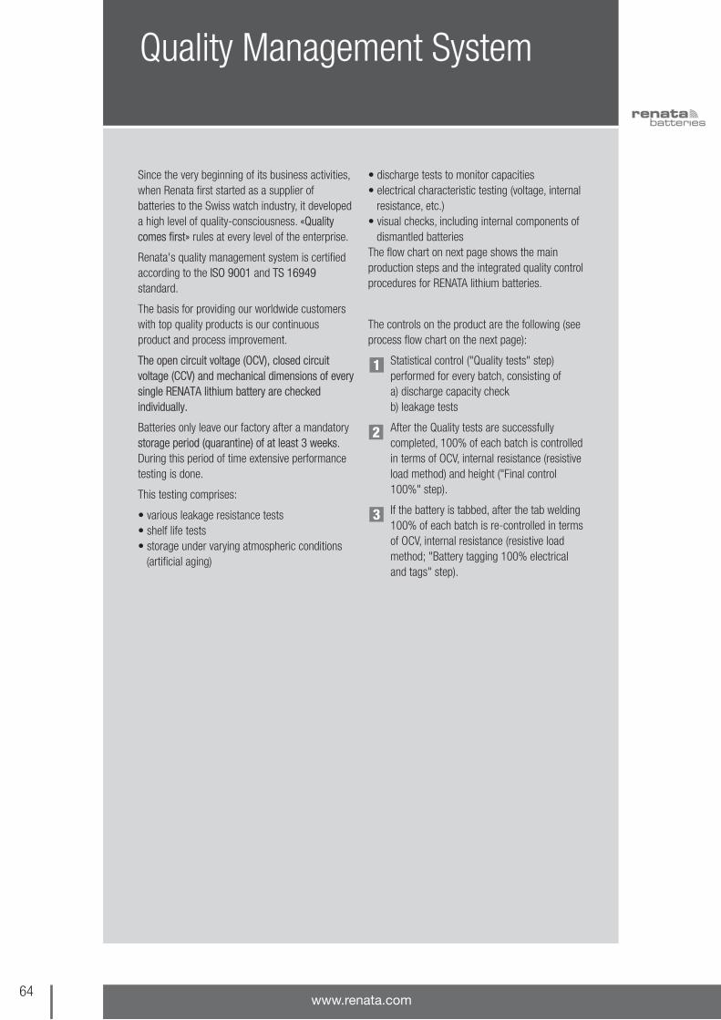
Quality Management System
Since the very beginning of its business activities,when Renata first started as a supplier ofbatteries to the Swiss watch industry, it developeda high level of quality-consciousness. «Qualitycomes first» rules at every level of the enterprise.
Renata's quality management system is certifiedaccording to the ISO 9001 and TS 16949standard.
The basis for providing our worldwide customerswith top quality products is our continuousproduct and process improvement.
The open circuit voltage (OCV), closed circuitvoltage (CCV) and mechanical dimensions of everysingle RENATA lithium battery are checkedindividually.
Batteries only leave our factory after a mandatorystorage period (quarantine) of at least 3 weeks.During this period of time extensive performancetesting is done.
This testing comprises:
• various leakage resistance tests• shelf life tests• storage under varying atmospheric conditions
(artificial aging)
• discharge tests to monitor capacities• electrical characteristic testing (voltage, internal
resistance, etc.)• visual checks, including internal components of
dismantled batteries The flow chart on next page shows the mainproduction steps and the integrated quality controlprocedures for RENATA lithium batteries.
The controls on the product are the following (seeprocess flow chart on the next page):
Statistical control ("Quality tests" step)performed for every batch, consisting of a) discharge capacity checkb) leakage tests
After the Quality tests are successfullycompleted, 100% of each batch is controlledin terms of OCV, internal resistance (resistiveload method) and height ("Final control100%" step).
If the battery is tabbed, after the tab welding100% of each batch is re-controlled in termsof OCV, internal resistance (resistive loadmethod; "Battery tagging 100% electricaland tags" step).
64www.renata.com
1
2
3

65the swiss power source
Process Flow Chart
Stamp lid Stamp cup Inject-mouldgasket
Treatment ofgasket
Press lithiumin lid
Separator-system Assembling battery
Washing of batteries
Pre-discharge
Quality tests
O.K.?
Yes
No
Final Control 100% Quarantine and inspection
Tags welding
Electrical and dimensions control
Packaging
Shipping
Press gasket on cup
Mixing MnO2powder
Washing of lid Washing cup Press tablet
Drying tablet
Electrolyte
1
2
3

ISO 9001
Certificates and Declarations
66www.renata.com

67the swiss power source
ISO/TS 16949
Certificates and Declarations

68www.renata.com
UL Safety ApprovaI
Certificates and Declarations
You can see the certificates for UnderwritersLaboratories Inc. Safety Approval at the UL OnlineCertifications Directory website. For that, click«Certifications» on www.ul.com and search for«Company Name»: Renata.
Renata's coin cells and Power Modules are listedunder file no. MH14002.
Renata's battery holders are listed under file no.E218732.
What is RoHS?European Union (EU) environmental legislationabout the RESTRICTION of the Use of certainHAZARDOUS SUBSTANCES (RoHS) in electricaland electronic equipment
What does RoHS imply?Member States shall ensure that, from 1 July2006, new electrical and electronic equipment puton the market does not contain:
• Lead (Pb), • Mercury (Hg), • Hexavalent Chromium (Cr), • Cadmium (Cd), • Polybrominated biphenyls (PBBs) and • Polybrominated diphenyl ethers (PBDEs)
Conformity with RoHS
RoHS: Affected products of the RENATA portfolio
Coin cellholders
Tabbedcoin cells
Batteries(incl. coin cells)
Batteries do notfall under the RoHS 2002/95/ECregulations
The pre-tinning of thesolder contacts usedto contain some lead
Batteries aregoverned by the
BatteryDirective2006/66/EC
Now they areleadfree
RENATAbatteries
comply withthis directive

69the swiss power source
Conformity with Battery Directive 2006/66/EC
Certificates and Declarations

70www.renata.com
Certificates and DeclarationsConformity with RoHS (bare batteries)

71the swiss power source
Certificates and DeclarationsConformity with RoHS (various lithium products)

72www.renata.com
This declaration of 0%mercury content will notbe renewed for the mercury content is nowdescribed in Renata'sRoHS certificates.
Certificates and DeclarationsMercury-free products

73the swiss power source
Conformity with IATA, ICAO and DOT regulations
Certificates and Declarations
Transportation of Lithium BatteriesThe transportation of lithium batteries is regulatedby the International Air Transport Association(IATA), the International Civil Aviation Organization(ICAO) and by the U.S. Department ofTransportation (DOT).
1. IATA and ICAO Special Provisions A45All RENATA lithium batteries are considered asnon-hazardous since they meet the SpecialProvisions A45, as published in IATA's handbook,41st edition, effective 1 January 2000.
These provisions require: "Batteries must beseparated so as to prevent short circuits and mustbe packed in strong packaging, except wheninstalled in electronic devices".
All RENATA Li/MnO2 cells or batteries have solidcathodes and contain less than 1 gram of lithiumor lithium alloy.
Also the batteries are approved in accordance toUN Spezial Provision SP 188-Manual of Tests &Criteria Part III Subsection 38.3.
2. DOT All RENATA lithium batteries are not subject to therequirements of the DOT Subchapter C,Hazardous Material Regulations because all ourbatteries meet the requirements of 49 CFR173.185(b).
Material Safety Data Sheets (MSDS) of eachreference are available on request.

74www.renata.com
Silver Oxide, Alkaline & Zinc Air Cells
Chemical System Dimensions Model CapacitySilver oxide (low drain), 1.55 V 4.8 x 1.6 mm 337 8 mAh
5.8 x 1.2 mm 335 6 mAh5.8 x 1.6 mm 317 10.5 mAh5.8 x 2.1 mm 379 16 mAh5.8 x 2.7 mm 319 21 mAh6.8 x 1.4 mm 339 11 mAh6.8 x 1.6 mm 321 14.5 mAh6.8 x 2.1 mm 364 20 mAh6.8 x 2.6 mm 377 28 mAh7.9 x 1.2 mm 346 9.5 mAh7.9 x 1.4 mm 341 15 mAh7.9 x 1.6 mm 315 19 mAh7.9 x 2.1 mm 362 24 mAh7.9 x 2.6 mm 397 32 mAh7.9 x 3.1 mm 329 37 mAh7.9 x 3.6 mm 384 45 mAh7.9 x 5.4 mm 309 80 mAh9.5 x 1.6 mm 373 29 mAh9.5 x 2.0 mm 371 40 mAh9.5 x 2.7 mm 395 55 mAh9.5 x 3.6 mm 394 84 mAh
11.6 x 1.6 mm 366 40 mAh11.6 x 2.1 mm 381 50 mAh11.6 x 3.1 mm 390 80 mAh11.6 x 3.6 mm 344 105 mAh11.6 x 4.2 mm 301 120 mAh11.6 x 5.4 mm 303 175 mAh
Silver oxide (high drain), 1.55 V 6.8 x 2.6 mm 376 27 mAh7.9 x 2.1 mm 361 24 mAh7.9 x 2.6 mm 396 32 mAh7.9 x 3.6 mm 392 45 mAh7.9 x 5.4 mm 393 80 mAh9.5 x 2.1 mm 370 40 mAh9.5 x 2.7 mm 399 55 mAh9.5 x 3.6 mm 380 82 mAh
11.6 x 1.6 mm 365 40 mAh11.6 x 2.1 mm 391 50 mAh11.6 x 3.1 mm 389 80 mAh11.6 x 3.6 mm 350 105 mAh11.6 x 4.2 mm 386 130 mAh11.6 x 5.4 mm 357 190 mAh
Alkaline, 1.5 V 11.6 x 4.2 mm LR43 75 mAh11.6 x 5.4 mm LR44 115 mAh
Zinc air, 1.4 V 11.6 x 5.4 mm ZA 675 650 mAh7.9 x 5.3 mm ZA 13 305 mAh7.9 x 3.5 mm ZA 312 175 mAh5.8 x 3.5 mm ZA 10 95 mAh5.8 x 2.1 mm ZA 5 33 mAh
In addition to the Lithium range of coin cells, the RENATA portfolio also includes the following batteries:

75the swiss power source
How to find us
BaselGermany
Italy
France
Itingen SissachLiestal
Augst
Härkingen Wiggertal
Birrfeld
Luzern
Bern
Zürich
• Exit Sissach (A2)• Direction Liestal/ Itingen• Exit Itingen (H2)
A3
A1
A2
A2
A1
Basel
Itingen
SissachLiestal
essartsdnaL
y stationawliaR
Zürich Bern Luzern
03 essartsnezuerK
essartsfroD
Lausen
• Exit Itingen (A2)• Direction Itingen• Over the railway bridge• Right – direction Lausen• Left – Kreuzenstrasse 30, Renata SA, main entrance
A2
Renata SACH-4452 Itingen/SwitzerlandKreuzenstrasse 30Tel. +41 61 975 75 75

Notes
76www.renata.com