kinematic analysis of an electric stair- climbing wheelchair · kinematic analysis of an electric...
TRANSCRIPT

Ing. Univ. Bogotá (Colombia), 21 (1): 27-48, enero-junio de 2017. ISSN 0123-2126
Kinematic Analysis of an Electric Stair-Climbing Wheelchair1
Análisis cinemático de una silla de ruedas eléctrica escaladora2
Giuseppe Quaglia3
Walter Franco4
Matteo Nisi5
doi: 10.11144/Javeriana.iyu21-1.kaes
How to cite this article:
G. Quaglia, W. Franco, and M. Nisi, “Kinematic analysis of an electric stair-climbing wheelchair,” Ing. Univ., vol. 21, no. 1, pp. 27-48, 2017. http://dx.doi.org/10.11144/ Javeriana.iyu21-1.kaes
1 Submitted on: August 17th, 2016. Accepted on: November 16th, 2016. Fecha de recepción: 17 de agosto de 2016. Fecha de aceptación:16 de noviembre de 2016.2 Fecha de recepción: 17 de agosto de 2016. Fecha de aceptación: 16 de noviembre de 2016. Artículo de investigación científica y tecnológica. 3Master in Mechanical Engineering, Politecnico di Torino, Italy. PhD in Applied Mechanics, Mechanical System and Structures, Politecnico di Torino. Associate professor at Politecnico di Torino. E-mail: [email protected] PhD in Applied Mechanics, Politecnico di Torino, Italy. Assistant Professor at Politecnico di Torino. E-mail:[email protected] Master Degree in Mechanical Engineering, Politecnico di Torino, Italy. PhD student at Politecnico di Torino. E-mail:[email protected]

28 Giuseppe Quaglia, Walter Franco, Matteo Nisi
Ing. Univ. Bogotá (Colombia), 21 (1): 27-48, enero-junio de 2017
AbstractIntroduction: This paper presents the functional design and kinematic synthesis of a recent version of an electric stair-climbing wheelchair. Wheelchair.q: The proposed device represents the latest evolution of the ‘Wheelchair.q’ project and introduces several improvements over previous designs. This updated solution has greater stability during stair-climbing operation, and it satisfies the safety require-ments introduced by ISO 7176-28:2012, “Requirements and test methods for stair-climbing devices”. The main improvement presented concerns the regularity of the user trajectory during stair-climbing, which ensures a more comfortable perception. This result has been achieved by introducing a cam mechanism between the frame connected to the locomotion unit and the seat frame, which properly manages the seat orientation. With an appropriate cam profile, it is possible to compensate for the oscillations that are introduced on the wheelchair during the climbing sequence and allow the user to obtain a translational trajectory. Results: The proposed design and its working principle are first described and illustrated through schematic and graphic representations. A brief explanation of the procedure for obtaining the cam pro-file is also given. Two different architectures for the cam mechanism are then compared, and the advantages and disadvantages for each solution are identified. Finally, the kinematic wheelchair performances are tested through a simulation conducted in the MSC-ADAMS multibody environment. Conclusions: The results obtained with the simulation show the effectiveness of the proposed solution. The wheelchair is able to climb a staircase in a safe and regular way. Following studies will complete the design of the wheelchair with the aim to build a prototype for demonstrating the proposed working principle.
Keywordsstair-climbing wheelchair, architectural barriers, cam mechanism, wheelchair.q
ResumenIntroducción: En este trabajo se analiza el comportamiento de una silla de ruedas eléctrica para subir escaleras desde un punto de vista cinemático. Wheelchair.q: El dispositivo propuesto representa la última evolución del proyecto ‘Wheelchair.q’ e introduce varias mejoras con respecto a los diseños anteriores. Esta solución actualizada cuenta con una mayor estabilidad durante la subida de las escaleras, permitiendo llevar a cabo la tarea de una manera segura, cumpliendo la norma ISO 7176-28:2012. Sin embargo, las principales mejoras atañen a la regularidad de la tra-yectoria del usuario durante la subida de escaleras, lo cual permite obtener una percepción de comodidad mayor. Este resultado se ha logrado mediante la introducción de un mecanismo de leva que gestiona adecuadamente la orientación del asiento en lo que se refiere al bastidor de la silla de ruedas. Con un perfil de leva apropiado, es posible compensar la oscilación introducida en la silla de ruedas durante la secuencia de escalada, para que el usuario pueda obtener una trayectoria de traslación. Resultados: El diseño propuesto y su principio de funcionamiento se describen e ilustran en primer lugar a través de representa-ciones esquemáticas y gráficas, con una breve explicación sobre los procedimientos para obtener el perfil de leva. A continuación, se comparan las dos diferentes arquitectu-ras del mecanismo de leva y se identifican las ventajas y desventajas de cada solución. Por último, se prueban las prestaciones de la silla de ruedas cinemática a través de un simulacro en el ambiente de simulación MSC-ADAMS. Conclusiones: Los resultados obtenidos con la simula-ción muestran la efectividad de la solución propuesta. La silla de ruedas es capaz de subir una escalera de forma segura y regular. Los siguientes estudios completarán el diseño de la silla de ruedas con el objetivo de construir un prototipo para demostrar el principio de trabajo propuesto.
Palabras clavesubir escaleras, silla de ruedas, barreras arquitectónicas, mecanismo cam

29Kinematic analysis of an electric stair-climbing wheelchair
Ing. Univ. Bogotá (Colombia), 21 (1): 27-48, enero-junio de 2017
IntroductionThe development of devices that can improve people’s quality of life can be a noteworthy task for engineering researchers. An engineering project aimed at service for humans should begin by identifying a problem that reduces the quality of life of a significant number of people and then seek innovative and ingenious solutions that use the proper theoretical and technical tools for the engineering field, which should provide a feasible answer.
In this paper, a particularly novel solution for a stair-climbing wheelchair is proposed. The problem faced in this research is to improve mobility for people with disabilities, particularly with respect to the limits imposed by architectural barriers.
It has been estimated that in the U.S. “roughly 30.6 million individuals aged 15 years and older (12.6 percent of U.S. population) had limitations associated with ambulatory activities of the lower body” [1] and, in particular, that “about 3.6 mil-lion people (1.5 percent) used a wheelchair” [1] for daily mobility. The percentage increases if only the elderly are considered. Among people over 65 years of age, approximately 2.0 million people used a wheelchair (5.2 percent) [1]. The last point becomes more relevant when considering the aging world population. Based on the actual trend, the percentage of people over 60 years of age will reach 22% of the world population in 2050, but in 2000, it was only 10% [2]. These data highlight that ensuring adequate mobility for people who use wheelchairs will become an important issue in the coming years.
In fact, the main limitation for wheelchair mobility is represented by archi-tectural barriers. Despite actual legislation, architectural barriers are still present in many public and private buildings due to technical and economic aspects. In these situations, it is necessary to provide wheelchair users with a device that can climb obstacles to guarantee building accessibility in any circumstance.
Over the past several years, many researchers have addressed this topic, and many patents, articles and prototypes can be found in the literature. The

30
Ing. Univ. Bogotá (Colombia), 21 (1): 27-48, enero-junio de 2017
Giuseppe Quaglia, Walter Franco, Matteo Nisi
different solutions, independent of the locomotion systems adopted for the stair-climbing ability [3], can be classified according to ISO 7176-28 [4], which considers wheelchair functionality, as summarized in Figure 1. In particular, three aspects are considered:1. whether the device can be used autonomously by the user.2. whether the device is self-standing during the stair-climbing sequence. 3. whether the device is a stair-climbing wheelchair carrier or a stair-climbing
wheelchair.
Figure 1. Classification based on functionality
Assistant-operated stair-climbing device Occupant-operated stair-climbing device
Self-standing Manually stabilized Self-standing Manually stabilized
Stair-climbing chair
Stair-climbing wheelchair carrier
Stair-climbing chair
Stair-climbing wheelchair carrier
Stair-climbing chair
Stair-climbing wheelchair carrier
Stair-climbing chair
Stair-climbing wheelchair carrier
Type A Type B Type C Type D Type E Type F Type G Type H
Source: ISO 7176-28.
The wheelchair presented in this paper should be able to climb stairs in a comfortable and safe way, and it must be stable during climbing operation to be used autonomously by the user. Moreover, it must have the functionality, dimensions and weight of a traditional electric wheelchair; thus, it should also be useable on flat ground for daily mobility. For these reasons, the reference category is “Type E: Occupant-operated, self-standing stair-climbing chair”.
Several solutions belonging to this category can be found in the literature. In [5], a wheelchair with pure leg locomotion is proposed. This type of solution has a high climbing capability, but it requires a complex structure for both the actuation and the control systems. Moreover, the stability on stairs could be a critical aspect, and the seat oscillates due to leg movement during both stair-climbing and flat ground motion, thus causing an uncomfortable sensation for the user.
In [6]-[8], hybrid track-wheel architectures are presented. This hybrid solution combines the high effectiveness of wheel locomotion on flat ground with the performance of a track on stairs. In particular, the main advantages of tracks are the stability and regularity of the trajectory during stair-climbing. The drawback is represented by the dimensions and weight involved in the use

31
Ing. Univ. Bogotá (Colombia), 21 (1): 27-48, enero-junio de 2017
Kinematic analysis of an electric stair-climbing wheelchair
of a motorized track. However, this solution is one of the most effective, and it is used in most commercial stair-climbing wheelchairs.
Another type of hybrid architecture is represented by wheelchairs that use leg-wheel locomotion, as in [9]-[12]. In these cases, the efficiency of wheels on flat ground is coupled with the effectiveness of legs for the obstacle-climbing task. The main advantage of this solution is related to the small dimensions and weight of the mechanism that is required to perform the obstacle climbing, but generally, the complexity of the actuation and control system increases. A subset of the hybrid leg-wheel locomotion is constituted by systems that use rotating leg locomotion, as in [13] and [14], in which this working principle is applied to mobile robots. This smart architecture allows the mechanical struc-ture to be simplified and requires fewer sensors and actuators. In the stair-climbing wheelchair field, this working principle has been applied in solutions that use cluster wheel locomotion units, such as those in [15]-[18]. Even if this archi-tecture permits simple and lightweight mechanisms, the drawback is that most of the solutions are not statically stable during stair-climbing and that the stability must be guaranteed through dynamic control. Moreover, the user trajectory during stair-climbing is not regular due to the oscillations introduced by the rotating leg system. The authors of this manuscript have worked on effective solutions to this problem for several years and have designed five versions of a stair-climbing wheelchair named ‘Wheelchair.q’ (see [19-23], which is presented below.
In this paper, a brief review of the previous versions of ‘Wheelchair.q’ is first presented. Then, a detailed analysis of the latest design is conducted, with par-ticular attention paid to the innovations introduced to obtain a regular trajectory for the user during stair-climbing. In particular, different architectures for a cam mechanism that manages the seat orientation are proposed and discussed. Finally, a multibody model of the wheelchair is presented, and the kinematic results related to the wheelchair performances during stair-climbing operation are given.
1. ‘Wheelchair.q’All versions of ‘Wheelchair.q’ are characterized by a cluster wheel locomotion unit that guarantees a simple climbing mechanism coupled with small dimen-sions and weight (Figure 2).

32
Ing. Univ. Bogotá (Colombia), 21 (1): 27-48, enero-junio de 2017
Giuseppe Quaglia, Walter Franco, Matteo Nisi
Figure 2. Cluster wheels locomotion unit
Rotating Frame (1)
Planet Gear (4)Idle Gear (3)
Solar Gear (2)
Wheel (5)
5
32
14 MsMs
Mp
Ms stands for solar motor and Mp stands for planet carrier motor. Source: authors’ own elaboration
The locomotion unit is composed of a rotating frame with three legs and an internal epicyclical mechanism. The rotating frame works as a planet carrier. The central solar gear is coupled to three idle gears, and each idle gear is cou-pled to a planet gear connected to the locomotion unit wheel. The idle gears are necessary to obtain the same rotational direction for both the solar and the planet gears. Each locomotion unit has two degrees of freedom: the rotation of the solar gear with respect to the planet carrier and the rotation of the planet carrier with respect to the wheelchair frame.
The actuation system of the two locomotion units (left and right), as described in [19], uses three motor-reducers, and it is represented in Figure 2. The two degrees of freedom of each locomotion group are controlled independently. Each solar motor (Ms) is connected to the solar gear of the corresponding locomotion group, and the single planet carrier motor (Mp) is linked to both planet carriers through a 1:3 transmission gear system that allows each shaft rotation to be coupled with a step ascent or descent (120° of planet carrier revolution).
During motion on flat ground, only the Ms motors are used, and the Mp motor is stopped. The Ms motors, through the transmission system, define the speed of rotation of the left and right groups of wheels, and thus, it is possible to obtain straight or curved trajectories. During the stair-climbing motion, the three motors cooperate to obtain the revolution of the planet carrier and advancement on the step. The drawback of this smart and compact solution is represented by the irregularity of the stair-climbing trajectory. The center of the locomotion

33
Ing. Univ. Bogotá (Colombia), 21 (1): 27-48, enero-junio de 2017
Kinematic analysis of an electric stair-climbing wheelchair
unit moves on a trajectory, as shown in Figure 3, that is similar to a cycloid and depends on the stair dimensions. Thus, it is necessary to introduce some further elements to obtain the requested regularity for the climbing trajectory.
Figure 3. Trajectory of the locomotion unit center during stair-climbing
Source: authors’ own elaboration
Furthermore, the necessity of device stability requires the addition of a sec-ond foothold for the wheelchair. The proper choice and correct design of this second contact point between the wheelchair and the stair have been the focus of the wheelchair evolution process that has been conducted to gain stable con-figurations and regular climbing trajectories. In [19], a review of the different proposed versions and the advantages and disadvantages of each one is given. Briefly, in the first and second versions of ‘Wheelchair.q’ four cluster wheels units are mounted: the two front units are idle, and the rear ones are motorized. This solution solves the stability issue but increases the oscillations generated on the wheelchair due to the asynchronous rotation of the front and rear units. In the third and fourth versions, the oscillation issue is partially solved with the introduction of a hybrid architecture. The front idle units are substituted with an idle track that smooths the wheelchair trajectory during stair-climbing.
Finally, a fifth version (’Wheelchair.q05’) has been developed, and it is pre-sented in this paper. It is still characterized by a hybrid architecture, but the two

34
Ing. Univ. Bogotá (Colombia), 21 (1): 27-48, enero-junio de 2017
Giuseppe Quaglia, Walter Franco, Matteo Nisi
cluster wheel locomotion units are mounted on the front, and an idle track is mounted on the rear to improve the device static stability. The most important result obtained with this new version is represented, however, by an improvement of the regularity in the climbing trajectory. The proposed idea is to introduce a cam mechanism with the aims of compensating for the oscillations generated by the locomotion unit and obtaining a translational motion for the seat. Figure 4 shows a scheme of the proposed architecture. Figures 11-14 give a complete description of the functional design of the wheelchair. The seat is fixed on the element RC that is hinged at S with the idle track. The segment T
U-T
D
defines the linear surface of the track that can be in contact with the corners of each stair step. If the track length is greater than the double of the distance between the stair edges, the point S moves in a straight trajectory. The frame PC is connected to the center of the locomotion unit in P, and during the step climbing sequence, it consequently oscillates with the locomotion unit rotation. The proposed cam is rigidly connected with the locomotion unit, and it manages the distance PR. If the cam profile is properly designed, it is possible to obtain a translation for element RC independent of the movement of the frame PC.
Figure 4. Schematic representation of the proposed architecture
TU
W
TD
C SRP
TD
TD'
C'S'
TU
TU'
C
P
R
R'
b b'
θp
θP'P'
S
W
Source: authors’ own elaboration
A theoretical approach to the problem is discussed in [24]. In that paper, a procedure for defining the proper cam profile is described, and an opti-mization process is proposed with the aim of identifying the cam shape that guarantees the highest performance. Here, a quick overview of the main results is given. In Figure 5, a scheme that describes the procedure necessary to obtain the correct cam profile is illustrated. In the kinematic inversion proposed in the

35
Ing. Univ. Bogotá (Colombia), 21 (1): 27-48, enero-junio de 2017
Kinematic analysis of an electric stair-climbing wheelchair
figure, the locomotion unit planet carrier is fixed while the frame PC rotates around P. The rotation is described by angle θ
P, which defines the relative po-
sition between the planet carrier and the frame PC. For each position of the locomotion unit (i.e., for each value of θ
P), the value of the angle b necessary
to obtain a constant orientation for the seat frame RC can be calculated. The variation of angle b must be equal and opposite to the variation of the orientation of the frame PC. Once the function b(θ
P) is known (see [24]), the cam profile
described by the polar coordinates (hCAM
, δ) can be obtained using Eqs. (1)-(3). In general, the trajectory of the point P and, thus, the wheelchair frame oscillation depend on the stair geometry. However, a simplified trajectory for the point P can be considered by replacing the real one with a sequence of circular arcs. This simplification introduces errors into the compensation of the frame oscillation but permits the simplification of the cam design. Indeed, with this assumption, the oscillation amplitude of the frame PC depends only on the displacement of point P in the direction perpendicular to the line connecting the step edges. Hence, the cam profile is affected only by the locomotion unit dimensions, and it does not depend on the stair slope. Thus, once a satisfactory cam profile has been identified, it can be used independently by the stair geometry. In the re-sult section, the error committed in the compensation of the wheelchair frame oscillation due to this simplification will be evaluated.
Figure 5. Scheme used to obtain the correct cam profile. Information related to equations (1) (2) and (3)
Ro
Co
C
W
bo
δo
Po
δ1 eo
e'
θpo
R'
hCAM'
hCAM0
Source: authors’ own elaboration
36
Ing. Univ. Bogotá (Colombia), 21 (1): 27-48, enero-junio de 2017
Giuseppe Quaglia, Walter Franco, Matteo Nisi
hCAM = lPC2 + lRC
2 2lPClRC cos (1)
= sin 2 lRC
hCAM
sin (2)
δ = e + θp (3)
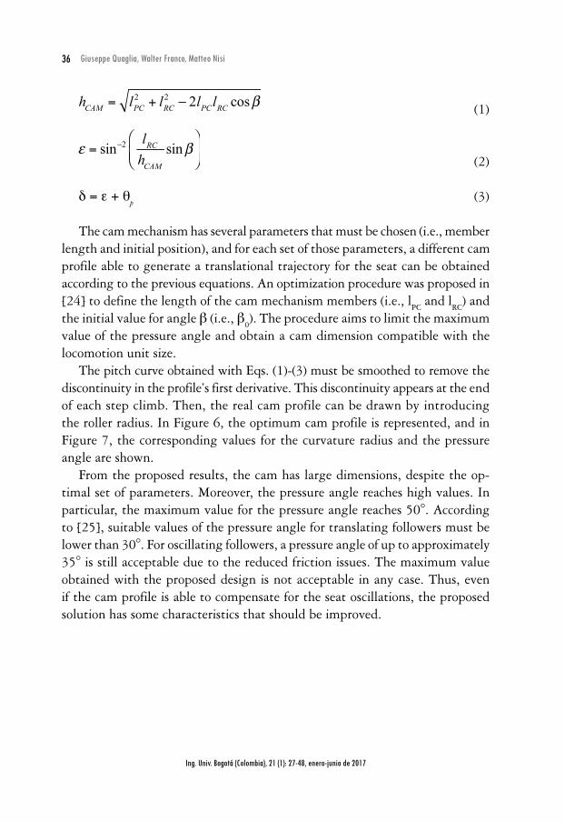
The cam mechanism has several parameters that must be chosen (i.e., member length and initial position), and for each set of those parameters, a different cam profile able to generate a translational trajectory for the seat can be obtained according to the previous equations. An optimization procedure was proposed in [24] to define the length of the cam mechanism members (i.e., l
PC and l
RC) and
the initial value for angle b (i.e., b0). The procedure aims to limit the maximum
value of the pressure angle and obtain a cam dimension compatible with the locomotion unit size.
The pitch curve obtained with Eqs. (1)-(3) must be smoothed to remove the discontinuity in the profile’s first derivative. This discontinuity appears at the end of each step climb. Then, the real cam profile can be drawn by introducing the roller radius. In Figure 6, the optimum cam profile is represented, and in Figure 7, the corresponding values for the curvature radius and the pressure angle are shown.
From the proposed results, the cam has large dimensions, despite the op-timal set of parameters. Moreover, the pressure angle reaches high values. In particular, the maximum value for the pressure angle reaches 50°. According to [25], suitable values of the pressure angle for translating followers must be lower than 30°. For oscillating followers, a pressure angle of up to approximately 35° is still acceptable due to the reduced friction issues. The maximum value obtained with the proposed design is not acceptable in any case. Thus, even if the cam profile is able to compensate for the seat oscillations, the proposed solution has some characteristics that should be improved.

37
Ing. Univ. Bogotá (Colombia), 21 (1): 27-48, enero-junio de 2017
Kinematic analysis of an electric stair-climbing wheelchair
Figure 6. Optimum cam profile
200
100
0
-100
Pitch CurveSmoothed Pitch Curve
-300 -200 -100 0 100 200 300mm
mm
Smoothed Pitch CurveSmoothed Cam Profile
-300 -200 -100 0 100 200 300
200
100
0
-100
-200
mm
mmSource: authors’ own elaboration
Figure 7. Curvature radius and pressure angle for the optimum cam profile
4020
0-20-40
20 40 60 80 100 120 140 160
ρ (m
m)
20 40 60 80 100 120 140 160
θ pres
s (deg
)
θp (deg)
θp (deg)
50
0
-50
Source: authors’ own elaboration
For these reasons, an improvement of the first proposed architecture of ‘Wheelchair.q05’ has been conceived, and it is shown in Figure 8. The main idea is to introduce a transmission ratio between the locomotion unit and the cam. This allows, for example, the coupling of a complete rotation of the cam to a third of the rotation of the locomotion unit planet carrier, which corresponds to a single step climb. The cam rotation and the locomotion unit rotation are thus coupled by using a transmission ratio, i
C = Δθ
C/Δθ
P = 3. By adding this transmission ratio,
the constraint on the maximum value for the pressure angle can be satisfied

38
Ing. Univ. Bogotá (Colombia), 21 (1): 27-48, enero-junio de 2017
Giuseppe Quaglia, Walter Franco, Matteo Nisi
with a smaller cam. In Figure 9, the pitch curve, the smoothed profile and the real profile of the optimum cam are presented, and the trend for the pressure angle is shown in Figure 10. It is evident that with this new architecture, the dimensions of the cam with respect to the locomotion unit are reduced, and the maximum value for the pressure angle is lower, thus improving the overall performance of the mechanism. The maximum pressure angle value obtained with the new cam profile is approximately 36°, and thus, it can be accepted with respect to the design advice proposed in [25].
Figure 8. Schematic representation of an improvement for the proposed architecture
QP
Rb
C S
Θsθc
a
TDθP
TU
W
Source: authors’ own elaboration
Figure 9. Optimum cam profile with 3:1 transmission
250200150100
500
-50-100-150
-300 -200 -100 0 100 200 300
Pitch CurveSmoothed Pitch Curve
mm
mm-300 -200 -100 0 100 200 300
250200150100
500
-50-100-150-200
Smoothed Pitch CurveSmoothed Cam Profile
mm
mm
Source: authors’ own elaboration

39
Ing. Univ. Bogotá (Colombia), 21 (1): 27-48, enero-junio de 2017
Kinematic analysis of an electric stair-climbing wheelchair
Figure 10. Pressure angle for the optimum cam profile with 3:1 transmission
40
30
20
10
0
-10
-20
-30
-400 50 100 150 200 250 300 350 400
θp (deg)
θ PRES
S (º)
Source: authors’ own elaboration
Once the optimal cam profile has been chosen, the complete wheelchair design should be defined. In addition to the locomotion units, cam mechanism and frame, the wheelchair requires a rear contact point to be stable in any configu-ration on both flat ground and stairs. In Figure 11, a schematic representation of the wheelchair in these two configurations is given.
Figure 11. Wheelchair configurations for flat ground (left) and stair-climbing (right)
1
2
1
2
Source: authors’ own elaboration

40
Ing. Univ. Bogotá (Colombia), 21 (1): 27-48, enero-junio de 2017
Giuseppe Quaglia, Walter Franco, Matteo Nisi
During motion on flat ground, to obtain high efficiency and maneuverability, the rear contact is guaranteed by a pair of pivoting wheels. The idle track is not in contact with the ground, and it is packed away to limit the wheelchair dimension. In particular, the designed track is made of two parts that can slide, passing from a compact to an extended configuration. Before starting the stair-climbing sequence, the pivoting wheels must be lifted, and the track must be put into contact with the stair. In conclusion, two mechanisms are necessary to change the wheelchair configuration: a mechanism that can control the position of the pivoting wheels (labeled 1 in Figure 11) and a mechanism to manage the idle track position and configuration (labeled 2 in Figure 11). In Figure 12 and Figure 13, constructive representations of the wheelchair in the two different working conditions are given.
In Figure 12, the small dimension and the compactness of the proposed device can be noticed, and in Figure 13, the kinematic components of the proposed architecture are presented. The cam (labeled 1 in Figure 13) is coupled with a roller follower (2) that is mounted on the element RC. The cam is mounted on a shaft (5) that has on each side a gear (4). Each gear (4) is coupled with a gear (3) that is connected to the locomotion unit frame creating the i
C=3 transmis-
sion ratio. For a third of rotation of the locomotion unit, which corresponds to a single step climb, the shaft (5) makes a complete rotation. The previously defined motor-reducers, Mp and Ms, are not shown for clarity.
Figure 12. Constructive representation of the whole wheelchair on flat ground and on stairs
Source: authors’ own elaboration

41
Ing. Univ. Bogotá (Colombia), 21 (1): 27-48, enero-junio de 2017
Kinematic analysis of an electric stair-climbing wheelchair
The whole wheelchair has an estimated mass of 80 kg. The user mass is approximately 80 kg, so the total vehicle mass is 160 kg. The power required for climbing the high slope stair is roughly approximately 250 W, assuming 5 seconds for each step climb.
Figure 13. Detailed view of the kinematic elements of the wheelchair architecture
Source: authors’ own elaboration
2. ResultsTo validate the designed architecture, a multibody model of the wheelchair was created in a multibody simulation SW environment and it is represented in Figure 14. The simulations test the wheelchair working principle, verify the design of the transmission system and provide a detailed understanding of the behaviors, particularly for the cam mechanism during stair-climbing. The model was created to simplify the detailed architecture presented above: only the steady-state climbing sequence has been considered, and thus, all of the unnecessary components have not been modeled. In particular, the pivoting wheels, their actuation system and the reconfiguration mechanism connected to the track have been neglected. Otherwise, the locomotion units, their epicyclical mechanisms, the frame, the seat and the cam mechanism have been included. The simulation has been performed for the steady-state climbing sequence that begins in the configuration shown in Figure 14.

42
Ing. Univ. Bogotá (Colombia), 21 (1): 27-48, enero-junio de 2017
Giuseppe Quaglia, Walter Franco, Matteo Nisi
Figure 14. Multibody model developed in MSC ADAMS
Source: authors’ own elaboration
One of the interesting aspects that have been investigated with this model is the interaction between the proposed cam mechanism and different stair dimensions. As explained previously, the trajectory of the point P and the oscillations introduced on the wheelchair change with the stair dimensions. Thus, for each set of stair dimensions, a different cam profile should be used to obtain a translational trajectory for the seat. As described in [24], the problem has been solved by designing the cam profile for a nominal stair and accepting residual oscillations when the wheelchair climbs a non-nominal stair. In Figure 15, the dimensions for standard stairs (according to UNI 10804 – gen 1999) and the nominal stair are summarized. After the simulation, the amplitude of the residual seat oscillations can be analyzed to evaluate whether they can be considered acceptable with respect to user comfort.
The simulation results obtained show qualitatively that the proposed solu-tion works properly and that the wheelchair can climb a sequence of steps in a safe and regular way. In Figure 16, the trajectory of significant points of the wheelchair structure during the climbing of a high slope stair is presented.

43
Ing. Univ. Bogotá (Colombia), 21 (1): 27-48, enero-junio de 2017
Kinematic analysis of an electric stair-climbing wheelchair
Figure 15. Standard and nominal stair dimensions
e
P
asho
ho
mmP
mm as
emm
Low slope 145 350 22.5º 378.8
Medium slope 170 300 29.5º 344.8
High solpe 190 250 37º 314
Nominal stair 166.8 221.3 37º 277.1
Source: authors’ own elaboration
Figure 16. Comparison of significant point trajectories (190 mm × 250 mm stair)
(m)
(m)
1.5
1
0.5
05 5.5 6 6.5
User CM trajectoryPoint P trajectoryPoint S trajectory
Source: authors’ own elaboration
In particular, a comparison between the trajectory of point P and the trajectory of the user center of mass (CM) provides information about the effectiveness of the proposed cam mechanism. Starting from an oscillating trajectory of point P, the resulting trajectory for the user center of mass is almost straight. The details can be analyzed in Figure 17: the represented quantities are defined in Eq. (4), and they reference the scheme of Figure 8.
44
Ing. Univ. Bogotá (Colombia), 21 (1): 27-48, enero-junio de 2017
Giuseppe Quaglia, Walter Franco, Matteo Nisi
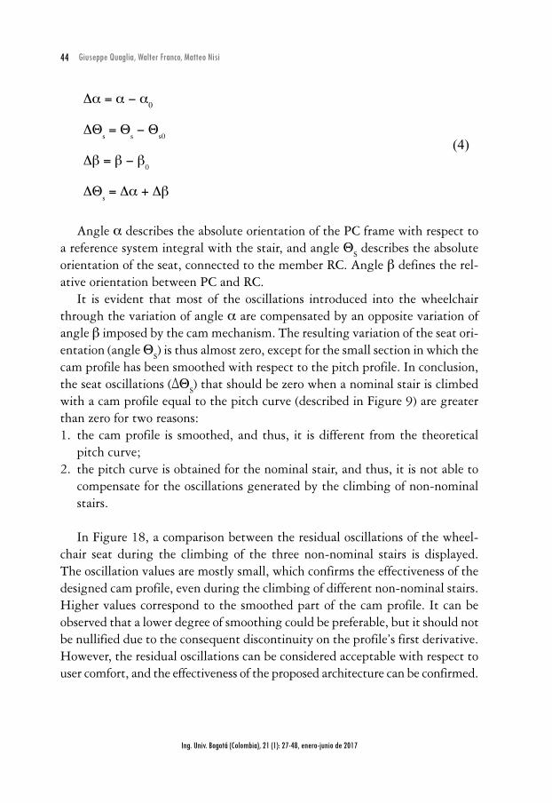
Da = a - a0
(4)DΘ
s = Θ
s - Θ
s0
Db = b - b0
DΘs = Da + Db
Angle a describes the absolute orientation of the PC frame with respect to a reference system integral with the stair, and angle Θ
S describes the absolute
orientation of the seat, connected to the member RC. Angle b defines the rel-ative orientation between PC and RC.
It is evident that most of the oscillations introduced into the wheelchair through the variation of angle a are compensated by an opposite variation of angle b imposed by the cam mechanism. The resulting variation of the seat ori-entation (angle Θ
S) is thus almost zero, except for the small section in which the
cam profile has been smoothed with respect to the pitch profile. In conclusion, the seat oscillations (ΔΘ
S) that should be zero when a nominal stair is climbed
with a cam profile equal to the pitch curve (described in Figure 9) are greater than zero for two reasons:1. the cam profile is smoothed, and thus, it is different from the theoretical
pitch curve;2. the pitch curve is obtained for the nominal stair, and thus, it is not able to
compensate for the oscillations generated by the climbing of non-nominal stairs.
In Figure 18, a comparison between the residual oscillations of the wheel-chair seat during the climbing of the three non-nominal stairs is displayed. The oscillation values are mostly small, which confirms the effectiveness of the designed cam profile, even during the climbing of different non-nominal stairs. Higher values correspond to the smoothed part of the cam profile. It can be observed that a lower degree of smoothing could be preferable, but it should not be nullified due to the consequent discontinuity on the profile’s first derivative. However, the residual oscillations can be considered acceptable with respect to user comfort, and the effectiveness of the proposed architecture can be confirmed.

45
Ing. Univ. Bogotá (Colombia), 21 (1): 27-48, enero-junio de 2017
Kinematic analysis of an electric stair-climbing wheelchair
Figure 17. Trend of significant angles (190 mm × 250mm stair): oscillation of the wheelchair frame (Δa), oscillation of the wheelchair seat (ΔΘS), and variation of the angle between the wheelchair
seat and the wheelchair frame controlled by the cam mechanism (Δb)
time (s)0 2 4 6 8 10 12 14 16 18
6
4
2
0
-2
DaDθs
Db
(º)
Source: authors’ own elaboration
Figure 18. Residual oscillation amplitude during non-nominal stair-climbing
time (s)0 2 4 6 8 10 12 14 16 18
5
0
-5
-10
-15
DΘ
s(º)
145 x 350170 x 300190 x 250
Source: authors’ own elaboration
The amplitude of the residual oscillation can be partially reduced with a reduction in the pitch curve smoothing. However, they cannot be fully can-celed in real applications due to the different geometries of the stairs that the

46
Ing. Univ. Bogotá (Colombia), 21 (1): 27-48, enero-junio de 2017
Giuseppe Quaglia, Walter Franco, Matteo Nisi
wheelchair can climb. In fact, it is not possible to design a cam profile that is suitable for any geometry because the amplitude of the frame oscillation changes with different stair dimensions. However, with the proposed cam design pro-cedure, a large amount of the seat oscillation can be canceled, regardless of the stair slope. A pure translational motion for the user can then be guaranteed by introducing a small actuation system with the aim of compensating for the residual oscillation of the seat.
ConclusionsIn this paper, a new version of a stair-climbing wheelchair has been presented. The objective of this new concept is the improvement of the device behavior, particularly with regard to user comfort during stair-climbing. With the intro-duction of a different architecture and, more specifically, the proper design of a cam mechanism that manages the seat orientation, the proposed objective has been achieved. The designed solution has been tested through a multibody model of the wheelchair, which has confirmed the effectiveness of the proposed working principle. The wheelchair can climb different stair typologies in a safe and comfortable way, and the user moves with an almost translational trajectory. The residual seat oscillations, even in non-nominal conditions, are small, and the overall wheelchair behavior can be considered appropriate. The following studies will regard the dynamic simulation of the proposed architecture to validate the designed actuation and control systems. Finally, a prototype (Figure 19) will be built with the aim of demonstrating the effectiveness of this stair-climbing device.
Figure 19. Rendering of a possible prototype for ‘Wheelchair.q’
Source: authors’ own elaboration

47
Ing. Univ. Bogotá (Colombia), 21 (1): 27-48, enero-junio de 2017
Kinematic analysis of an electric stair-climbing wheelchair
References[1] U.S Census Bureau, “Americans with Disabilities: 2010”, 2012.[2] W. Lutz, W. Sanderson, and S. Scherbov, “The coming acceleration of global population
ageing”, Nature, vol. 451, no. 7179, pp. 716-719, 2008.[3] L. Bruzzone, and G. Quaglia, “Review article: locomotion systems for ground mobile
robots in unstructured environments”, Mechanical Sciences, vol. 3, pp. 49-62, 2012.[4] ISO 7176-28:2012, “Requirements and test methods for stair-climbing devices”.[5] Y. Sugahara et al., “Walking up and down stairs carrying a human by a biped locomotor
with parallel mechanism”, Proc. Int. Conf. on Intelligent Robots and Systems (IROS), 2005, Edmonton, Alberta, Canada, pp. 1489-1494.
[6] S. Yu et al., “Configuration and tip-over stability analysis for stair-climbing of a new-style wheelchair robot”, Proceeding of International Conference on Mechatronics and Auto-mation (ICMA), 2010, Xi’an, China, pp. 1387-1392.
[7] Stair-climbing wheelchair, by R. T. Quigg, U.S. Patent No. 6,857,490, 22 Feb, 2005.[8] Powered wheeled vehicle capable of travelling on level ground, over uneven surfaces and
on stairs, by Hervé Marie Georges Le Masne, U.S. Patent No. 7,384,046, 10 Jun, 2008.[9] J. Yuan, and S. Hirose, “Research on leg-wheel hybrid stair-climbing robot, Zero Carrier”,
Proceeding of International Conference on Robotics and Biomimetics (ROBIO), 2004, Shenyang, China, pp. 654-659.
[10] M. J. Lawn, and T. Ishimatsu, “Modeling of a stair-climbing wheelchair mechanism with high single-step capability”, IEEE T. Neur. Sys. Reh., vol. 11, no. 3, pp. 323-332, 2003.
[11] A. González, E. Ottaviano, and M. Ceccarelli, “On the kinematic functionality of a four-bar based mechanism for guiding wheels in climbing steps and obstacles”, Mech. Mach. Theory, vol. 44, no. 8, pp. 1507-1523, 2009.
[12] A. Gonzalez et al., “Improving the mechanical design of new staircase wheelchair”, Ind. Robot, vol. 34, no. 2, pp. 110-115, 2007.
[13] G. Quaglia, L. Bruzzone, G. Bozzini, R. Oderio, and R. Razzoli, “Epi.q-TG: mobile robot for surveillance”, Ind. Robot, vol. 38, no. 3, pp. 282-291, 2011.
[14] U. Saranli, M. Buehler, and D. E. Koditschek, “RHex: A Simple and Highly Mobile Hexapod Robot”, Int. J. Robot Res., vol. 20, no. 7, pp. 616-631, July 2001.
[15] C. Chen, and H. Pham, “Design and fabrication of a statically stable stair-climbing robotic wheelchair”, Ind. Robot, vol. 36, no. 6, pp. 562-569, 2009.
[16] Y. Sugahara, N. Yonezawa, and K. Kosuge, “A novel stair-climbing wheelchair with transformable wheeled four-bar linkages”, Proceeding of International Conference on Intelligent Robots and Systems (IROS), 2010, Taipei, Taiwan, pp. 3333-3339.
[17] System and method for stair climbing in a cluster-wheel vehicle, by J. B. Morrell et al., U.S. Patent no. 6,311,794, 6 Nov, 2001.

48
Ing. Univ. Bogotá (Colombia), 21 (1): 27-48, enero-junio de 2017
Giuseppe Quaglia, Walter Franco, Matteo Nisi
[18] Battery powered stair-climbing wheelchair, by Kenneth Ray Cox, U.S. Patent No. 6484829, Nov. 26, 2002.
[19] G. Quaglia, W. Franco, and M. Nisi, “Evolution of Wheelchair.q, a Stair-climbing Whe-elchair”, Proceedings of the 14th IFToMM World Congress, Taipei, Taiwan, 2015.
[20] G. Quaglia, W. Franco, and R. Oderio, “Wheelchair. q, a mechanical concept for a stair climbing wheelchair”, Proceeding of International Conference on Robotics and Biomi-metics (ROBIO), 2009, Guilin, China, pp. 800-805.
[21] G. Quaglia, W. Franco, and R. Oderio, “Wheelchair. q, a motorized wheelchair with stair climbing ability”, Mech. Mach. Theory, vol. 46, no. 11, 2011, pp. 1601-1609.
[22] G. Quaglia, W. Franco, and M. Nisi, “Design of a reconfiguration mechanism for an elec-tric stair-climbing wheelchair”, Proceeding of the International Mechanical Engineering Congress & Exposition (IMECE), 2014, Montreal, Quebec, Canada.
[23] G. Quaglia, W. Franco, and M. Nisi, “Analysis of the static stability for an electric stair-climbing wheelchair”, Proceeding of the International Conference on Robotics in Alpe-Adria-Danube Region (RAAD), 2016, Belgrade, Serbia.
[24] G. Quaglia, and M. Nisi, “Design and optimization of a self-leveling cam mechanism for a stair climbing wheelchair”, Manuscript submitted for publication.
[25] R. L. Norton, Design of machinery: an introduction to the synthesis and analysis of mechanisms and machines, New York: McGraw-Hill Professional, 2004.