knowledge-based system for adaptive traffic signal...
TRANSCRIPT

TRANSPORTATION RESEARCH RECORD 1324 115
Knowledge-Based System for Adaptive Traffic Signal Control
S. MANZUR ELAHI, A. EssAM RADWAN, AND K. MICHAEL GouL
Signal Control at Isolated Intersection (SCII) is a knowledgebased expert system prototype. It represents an application of expert systems to adaptive signal control. The first generation of the prototype was developed at Arizona State University in 1987. The second-generation SCH can handle three types of intersection geometries. At the end of each signal cycle, SCn determines the performance of the controller operation during that cycle. In case of an unsatisfactory performance, sen determines the appropriate cycle length, phasing pattern, and split. It also updates t~e cycle length and phasing scheme based on traffic demand. Different tests validated and calibrated the prototype using a simulation approach. A 20-min traffic volume data set was used to simulate a pretimed controller, an actuated controller, and the operations suggested by sen. The tests demonstrated the potential of this prototype to reduce delay at isolated intersections.
Existing signal types are mainly classified as pretimed, semiactuated, and full-actuated, including volume-density controllers. In the pretimed operation, the intervals of signal phases are predetermined. In the semiactuated operation, the major road phase is nonactuated and the minor road phase is actuated. In the full-actuated operation, all phases are controlled by actuations created by the detectors. The phasing patterns and their associated intervals can vary to a large extent based on the traffic demand.
Full-actuated traffic operations may have an added feature, volume-density control, which is programmed to operate with variable minimum green time and vehicle extension intervals. In this feature, the phase interval can vary based on a more complex evaluation of traffic conditions.
Another new type of operation, called adaptive control, is still in a research stage. It represents a real-time, demandresponsive traffic signal control and performs the signal operation based on existing traffic conditions. Different strategies have been developed for adaptive signal control.
STATEMENT OF PROBLEM
The conventional type of signal controllers have several limitations. The pretimed controller has a fixed cycle time, split, and phasing pattern over a certain period of time. It cannot respond to fluctuations in traffic demand. Actuated controllers are more flexible in handling traffic fluctuations. How-
S. M. Elahi , Bureau of Traffic Services, District of Columbia Department of Public Works, 2000 14th St., N. W., 7th Floor, Washington, D.C. 20009. A. E. Radwan, Department of Civil and Environmental Engineering, University of Central Florida, Orlando, Fla. 32816. K. M. Gout, Department of Decision Information Systems, Arizona State University, Tempe, Ariz . 85287.
ever, their performance deteriorates under heavy traffic conditions when some phases reach their maximum duration and the green period per phase does not remain proportional to the traffic demand (1). Also, conventional controllers are often preset according to the traffic demand predicted by time of day; hence, some unanticipated demands cannot be handled. To improve signal performance, on-line signal control is desirable because it can adjust the signal plan based on real-time traffic conditions.
There are many good reasons for using artificial intelligence techniques to help solve traffic engineering problems. The design of signalized intersections involves many decisionmaking processes, for example, what kind of signal operation should be used, what signal phases should be used, and finally, what calculations should be made to find the timing scheme for the cycle. The application of knowledge-based expert system (KBES) technology can be a logical approach to handle this overall problem. The knowledge base of a KBES designed to capture the existing traffic condition, along with historic data, can generate the basis for signal control. With the ability to learn, it can continuously update its knowledge base and adapt to variations in traffic flow with the help of an inference engine.
A KBES has the ability to perform tasks using a humanlike decision process in a limited domain. Gou! et al. (2-4) identified the need for a KBES orientation to real-time signal control operation at isolated intersections and developed an expert system prototype in 1987 at Arizona State University. Radwan et al. (5) summarized the experiences from the project, especially during the verification of the system. The expert system prototype, Signal Control at Isolated Intersection (SeII), was developed for a specific intersection geometry and phasing pattern. In this paper, it is called first-generation sen, or SCII-1. This paper reports on research involved in enhancing sen. The product of this research is called secondgeneration sen, or SeII-2.
LITERATURE REVIEW
Delay Equations
Webster (6) pioneered the formulation Of a delay model for fixed-time traffic signal operation. This model has been used extensively in computer software. Modifications were made to Webster's formula to estimate stopped-time delay at pretimed signals in the Highway Capacity Manual (7). The manual describes a step-by-step procedure to find capacity and level of service for signalized intersections. Its measure of

116
effectiveness is average stopped-time delay, which is calculated by the following equation:
l - (g/C)]2 d = 0.38C [ _ (g!C)X] + 173X2[(X - 1)
+ '\/(X - 1)2 + 16Xlc] (1)
where
d = average stopped delay per vehicle for the lane group (sec/veh),
C = cycle length (sec), g = effective green time (sec), X = degree of saturation = vie ratio for the lane-group, c = capacity of the lane-group (veh/sec), and v = vehicle flow rate (veh/sec).
The first term in Equation 1 denotes delay for uniform arrivals; the second term denotes incremental delay for random arrivals. Because the vehicle arrival patterns may not really be random, the second term is subject to a correction for the signal progression and other factors. The Highway Capacity Manual discusses five different arrival patterns and assigns different correction factors to each of them.
Equation 1 yields reasonable values for values of X between 0 and 1.0. It may be used with caution for values of X up to 1.2.
Queue Equations
Queue length, like delay, is an important measure of effectiveness. Second-generation SCII determines the system effectiveness combining both measures. Different queue equations are available, including Webster's (6). Cronje (8) conducted research to assess existing formulas for delay, stops, and overflow. He defined overflow as the queue length at the end of the green phase. He took into consideration the formulas given by Webster (6), Newell (9), and Miller (10,11) and compared the results from these formulas with the results generated from a macroscopic computer simulation model. He observed that, among the overflow equations assessed, Miller's second overflow equation produced values closest to the simulated values. This finding is adopted in this study; therefore Miller's second equation was used to calculate the queue length for undersaturated conditions. The equation is as follows:
Qo = exp[-(4/3) *(A* C * s)0•5
* (1 - X)/X]/[2(1 - X)]
where
exp[z] = e', A = G/C ratio, G = effective green (sec), s = saturation flow (veh/sec), v = arrival rate of vehicles (veh/sec), c = capacity (veh/sec) = s * A = s * G/C, and
Q0 = average overflow at the beginning of red.
(2)
TRANSPORTATION RESEARCH RECORD 1324
To calculate the queue length (Q) at the beginning of the green, the number of vehicles that arrived during red (Q,) should be added to Q0 . For the arrival rate of v and the red interval of r
Q, = v * r
V*(C-G)
v * c * (1 G/C)
= v * C * (1 - A) (3)
Finally,
Q = Qo + Q, (4)
The above queue-length model is good for undersaturated conditions only. For near and oversaturated conditions, a deterministic model has been considered (12). This model ignores the effects of random variations. This concept is used to develop a method for estimating queue length, referred to as the input-output method. This method assumes a constant rate of vehicle input and output at an intersection. Because vehicles waiting in a queue provide a steady source of input during saturated conditions, this is identified as a suitable method. Let Q;_ 1 be the queue length at the end of a cycle (i - 1). During the Cycle i, the expected overflow in the green interval is (v - s) * g and the additional queue buildup during the red interval is v * r. Then, the expected queue length at the end of a Cycle i can be estimated as
Q; = Q;_ 1 + (v - s) * g + v * r (5)
where the term (v - s) * g cannot be less than zero. A combination of Equations 4 and 5 was coded in the
prototype SCII-2, where Equation 4 was used for undersaturation and Equation 5 was used for near- and oversaturation.
Expert System
One definition of the term expert system is "An expert system is a computer program that embodies the expertise of one or more experts in some domain and applies this knowledge to make useful inferences for the user of the system" (13).
An expert system has two components, namely,
1. Knowledge base, and 2. Inference engine.
The knowledge base contains all facts revealed by the expert for the problem. The inference engine determines the portion of the knowledge base required to solve a particular problem.
The use of expert systems in transportation engineering is relatively new. Work in this field includes CHINA, for highway noise barrier design; DIRECTOR, for urban transportation education; SCEPTRE, for pavement rehabilitation, and TRALI, for traffic signal setting.

Elahi et al.
Computer Applications and Adaptive Control Strategy
The application of expert systems in adaptive control strategies in designing the operation of signalized intersections is a completely different approach than that used in existing signal control software applications. Most of the available software applications now are applicable to pretimed signal operation. Bullen et al. (14) discussed the limitations of a number of available software systems that can be applied for actuated signals. The TEXAS model does not have any optimization capability for signal timing. SOAP84 is capable of providing optimal design but it is highly dependent on Webster's approach (6), which is mainly for pretimed signals. NETSIM is another software application that can deal with vehicle-actuated operation, but again it does not have an optimization capability.
VIPAS (14) can analyze a wide range of phasing patterns and different types of signals including full-actuated controllers. It is designed for isolated intersection and is able to optimize and analyze a variety of intersections.
Zozaya-Gorostiza and Hendrickson (15) developed a KBES prototype, TRALI, to assist traffic engineers in signal timing decision making. TRALI does not have a real-time signal control strategy, but rather provides design parameters. TRALI is coded in the OPS5 programming environment. It uses heuristic rules to determine phase distribution, calculates the optimum cycle length, and estimates delay by Webster's formula.
Much attention is currently being paid to adaptive control strategies. Gartner (16) developed a software application called Optimization Policies for Adaptive Control (OPAC) to perform an adaptive control strategy. The first version of OPAC, OPAC-1, uses a dynamic programming approach, which is a mathematical optimization of multistage decision processes. The subsequent version, OPAC-2, uses a simplified approach. The rolling horizon concept was used later. This concept is mainly used by operations research analysts in productioninventory control.
The latest version of OP AC (17) is in real time and has been tested in the field. The field results indicated that it performed better than actuated signals, especially at a higher demand level.
Lin et al. (18) tested an adaptive control strategy based on predicted data. This strategy did not achieve much success. Lin et al. used three predictors: (a) an exponential smoothing technique, (b) a double exponential smoothing technique, and (c) a pattern search predictor using a heuristic algorithm. None of the predictors consistently produced the smallest prediction error. They selected the exponential smoothing technique for simplicity and compared it with pretimed control. It was found that their strategy did not improve the signal performance.
Lin et al. (19) developed another adaptive control strategy, Stepwise Adjustment of Signal Timing (SAST). Its logic divides time into discrete intervals or steps. In each step, a decision is made with available limited future information on whether to terminate the green phase at the end of the step or to extend it beyond the step.
The TRALI expert system (15) is identified in assisting a traffic engineer in signal timing decision making. In contrast to this approach, sen is a tool for signal control at an intersection in real time.
117
SCII-1 was developed to emulate an adaptive controller using artificial intelligence. Radwan et al. (5) described their experiences during the development of sen and documented different phases of the development framework. Verification of SCil-1 provided important insights about the prototype's performance. Gou! et al. ( 4) provided an overview of the prototype.
OVERVIEW OF SCII-2 PROTOTYPE
The first-generation SCII was a milestone for expert system applications in adaptive signal control. The prototype was expanded so that it could perform better and could be applied to a variety of situations. This section describes the modifications and current status of SCII-2.
Modifications
The SCII-1 prototype ( 4 ,5) was limited with respect to the type of intersection geometry and signal phasing schemes it could accommodate. The major enhancements of SCII-1 are as follows:
1. SCII-1 was developed for a single set of geometric configurations. SCII-2 was made more robust to handle two other configurations of intersection geometries.
2. SCil-1 was designed for adaptive control operation. SCil-2 was expanded to handle both adaptive control and conventional type of signal operations. The adaptive control mode of operation is the subject of this paper.
3. SCII-1 was designed for a fixed four-phase operation. SCII-2 can choose the appropriate phasing pattern · for particular traffic demand patterns.
4. In SCil-1, cycle durations are based on total intersection critical volume. In SCII-2, the cycle time logic was modified. A more versatile method was adopted, including saturation flow as another factor.
5. SCII-1 uses vehicle delay as the sole performance measure. In SCII-2, queue length was incorporated as an additional performance measure.
6. The prototype was enabled to perform as a simulator so that SCII-2 can determine the delay and queue length for a given set of data.
7. Initial validation was done to the prototype.
Overall Architecture
SCII-2 has been coded in LISP on a microcomputer. The top level of SCII-2 asks the user whether the mode of operation will be conventional (actuated and pretimed) or adaptive control (Figure 1).
If the user selects the conventional mode, SCII-2 evaluates the signal performance at the end of each cycle and determines the point where signal control needs to be switched from actuated to pretimed and vice versa. SCil-2 uses the methodology outlined in NCHRP Report 233 (1) to determine the appropriate mode of signal operation under specific traffic conditions.
The adaptive control operation strategy constitutes the major portion of SCII-2's computer code. SCII-2 evaluates the

118
TOP-LEVEL
Conventional or Adaptive Control?
Conventional Adaptive
Actuated or Pretimed?
Operation with user specified signal data
FIGURE 1 Overall architecture of SCII-2.
New signal timing plan, if required
Adaptive Control
signal performance at the end of each cycle. If the performance level falls below some user-set threshold value, seII-2 will determine the parameters for a new cycle.
The knowledge base enables SeII-2 to remember past data that are necessary for critical computations in different modules of this prototype. The heart of the knowledge base is a fusion of multiple data bases; each unit data base represents a specific 15-min interval and stores the related historic traffic volume data broken down by movement type based on signal cycles. SeII-2's knowledge base also includes a data base for signal effectiveness over past cycles. A KBES should possess the capability of "self-adaptation," or learning. In this context , sen has the ability to adapt its historical data in case of new data.
Adaptive Control Procedure
The basic procedure of SC11-2's operation in the adaptive control mode is described in the following steps:
• Step 1: At the end of each signal cycle , this prototype uses the traffic count in that cycle to determine the level of service of each approach and the overall intersection . It follows the procedure described in Chapter 9 of the Highway Capacity Manual (7). The prototype also calculates the queue to be expected at the start of the green using Equation 4 or Equation 5, depending on the degree of saturation.
• Step 2: The prototype converts the delay and queue length into a performance rating . If this value is higher than the userset threshold value, it continues with the existing signal timing, skips Step 3, and performs Step 4 directly; if not, it performs Step 3.
• Step 3: The prototype forecasts the traffic volume expected in the next cycle based on the "current" cycle traffic volume data and a data base mean of previous volume data. Then it recalculates the signal timing for the forecasted volume. A table look-up procedure is used to determine the cycle length corresponding to the sum of critical volume/saturation
TRANSPORTATION RESEARCH RECORD 1324
flows (vis ratios) on each street. If the user has not predetermined any phasing pattern, SCII-2 will determine a reasonable phasing pattern. Then it calculates the green intervals for the phases based on the vis ratio. It performs the volume, saturation flow rate, and capacity analysis modules using the timing scheme as outlined in Chapter 9 of the Highway Capacity Manual.
•Step 4: SCII-2 maintains a data base of significant volume data of previous cycles. It checks whether the "current" traffic volume represents a new trend not reflected in the data base. If so, it stores the data in the data base. The prototype loops back to Step 1 to analyze the next cycle.
Intersection Geometries
SCII-2 can handle three different types of four-legged intersections:
1. Each approach with two through lanes and one exclusive left-turn lane,
2. Each approach with three through lanes and one exclusive left-turn lane, and
3. Each approach with one through and one shared leftturn lane.
Phasing Pattern
The second-generation Sell can analyze up to eight different type of phases (Figure 2), of which a maximum of six phases can occur in a single cycle. The user must define whether the left-turn movement is protected or permissive. SCII-2 determines the different lane groups in accordance with the methodology in Chapter 9 of the Highway Capacity Manual (7). Then it determines the vis ratio for all the lane-groups. To choose the appropriate phasing pattern, it follows an algorithm that is based on some simple rules of thumb. SeII-2 provides green times to each phase in proportion with the vis ratio. For a particular street (e.g., north-south), if there is a demand for the left-turn phase for both approaches, sen-2 will select a dual left-turning Phase A with green time proportional to the smaller demand (see Figure 2). If either of the two approaches has uemand for the left turn, it will switch to either Phase B or C. Phase D then follows. If both leftturning demands are met simultaneously, SeII-2 will skip Phases B and C and switch directly to Phase D . This is also true for the east-west directions.
Performance Grade of SCII-2
Delay is an important measure of effectiveness (MOE) that has been used in the Highway Capacity Manual procedure for signalized intersections. SCII-1 uses delay as the performance measure. To fine-tune a signal setting, an expert may judge the performance of the operation by the visual inspection of the queue length. Because of the significance of queue length as another important MOE, an enhanced performance measure is calculated in SeII-2 combining both MOEs. SeII-2 calculates performance grades for both queue and delay on a 0-100 scale using several heuristics. These two grades are

Elahi et al.
CD ® Phase A Phase B
© 0 Phase E Phase F
FIGURE 2 Eight-phase signal operation.
then combined to yield one value on the basis of user-chosen weights. The following paragraphs discuss the calculation procedure of queue and delay grades.
Delay Grade
The delay grade is calculated on a 0-100 scale using several heuristics. The 100 points are based on the following components:
1. Approach level of service, 2. Intersection level of service, and 3. Improvements over past cycles.
Queue Grade
Queue length can produce a grade of maximum 100 and minimum 0. A numeric value is calculated for each lane group corresponding to the average queue length per lane prevailing at the start of green period. A maximum value of 100 is achievable for each lane group for a zero queue length. A minimum grade of 0 can occur when queue length exceeds some threshold value. This threshold value is currently set at 25. This value was developed for a downtown area where the signals are 600 to 700 ft apart. Assuming 625 ft for the distance between two signals and 25 ft for the distance between two vehicles front bumper to front bumper, a block can contain 625125 = 25 vehicles. For this case, a value of 0 is assigned for a queue of at least 25 vehicles and 100 is assigned for a queue length of 0. Intermediate values are calculated by linear interpolation. In the following, QL represents queue length.
Rating = (25 - QL) * 100125 for QL '.'.S: 25
= 0 for QL > 25
This threshold value can be changed depending on the specific block length.
Combined Grade
Once both the delay grade and the queue grade have been calculated, the combined grade ( G) is calculated using user-
119
GU ® Phase c Phase D
C3 0 Phase G Phase H
selected weights W v and W Q:
(6)
when W v + W Q = 1.
Cycle Length Logic
In addition, the optimum cycle length is determined from a two-dimensional table as a function of the sum of the critical vis on each road. This is an approximate, but quick and simple method for determining the optimum cycle length. This method was adopted instead of a full-scale optimization procedure, because the prototype needs fast computations for real-time control. Tables were generated using a computer program to search for minimum delay for varying vis on different approaches using the Highway Capacity Manual (7) delay equation. Two boundary constraints are placed on the values looked up from these tables. The upper boundary limit for the cycle length is chosen to be 150 sec; a lower limit of 40 sec is selected.
Forecasting Model
The forecasted volume is a weighted combination of the most recent volume and data base mean. A smoothing factor has been introduced to reduce the adverse impact of abrupt rise and fall in the traffic volume. SCII-2 stores a separate data base for each 15-min interval. SCII-2 can keep track of time elapsed and locate the appropriate part of its knowledge base to extract volume information.
Delay Model
SCII-2 calculates delay using the Highway Capacity Manual (7) delay equation, documented as Equation 2.
Queue Model
A hybrid model was built to calculate the queue length in the second-generation SCII. Miller's queue model (Equation 4)
120
is used for undersaturated traffic conditions. For near- and oversaturation, SCII-2 uses the input-output model (Equation 5). The cut-off point for the shift from one method to the other has been determined to be at a degree of saturation X = 0.98. A set of calculations was made to determine this boundary point.
Assumptions in SCII-2
Several assumptions were made in the development of SCII-2, as shown in Table 1. These assumptions are not limitations of the prototype, but they can be easily changed in the SCII-2 coding. These assumptions are also realistic for many intersections.
System Requirements
SCII-2 is designed for an IBM-compatible microcomputer. It requires random access memory (RAM) of 512k bytes.
TESTING WITH SIMULATION
Once an expert system prototype is developed, the next logical step is to adjust its parameters. Because SCII-2 is designed to dynamically change the traffic signal settings, a fine-tuning process for the heuristic parameters was needed.
Computer simulation is a cheap and safe tool for numerous "what if" types of analyses. This type of test provides some insights on the model performance. A microscopic computer simulation model (like NETSIM or TEXAS) could be used to test the different settings proposed by SCil-2. Furthermore, the simulation exercise and the results obtained from the simulation runs could provide insight to how well SCII-2 responded to traffic variations and what values to use for particular heuristic parameters. For this study, the TEXAS model was used for testing SCII-2 because this simulation model is developed solely for isolated intersections. Vehicles may be generated using any distribution dictated by the user, such as the shifted negative exponential distribution, the Erlang distribution, or others. The NETSIM computer model uses only a uniform vehicle arrival approach, which may not be suitable for simulating traffic at isolated intersections.
TABLE 1 ASSUMPTIONS MADE IN sen conditions Elements Assumption
Geometric Area Type CBD Conditions Lane widths 12 feet
Grade Level Parking Not allowed
Traffic Peak hour factor 1. 0 Conditions Percent heavy vehicles 0
Pedestrians None Buses stopping per hour None Arrival type Totally random
Signalization All red 0 sec Conditions Yellow 3 sec
Ideal saturation flow 1800 vph
TRANSPORTATION RESEARCH RECORD 1324
Texas Model
TEXAS is a microscopic simulation model developed at the University of Texas at Austin (20). It is a microcomputerbased software application that can make simulation runs for a specified simulation time. Replications of the same run can be made using different random number seeds.
The model can simulate most of the intersection geometric configurations. Pretimed and actuated signal controls can be evaluated.
Initial Fine-Tuning of SCII-2
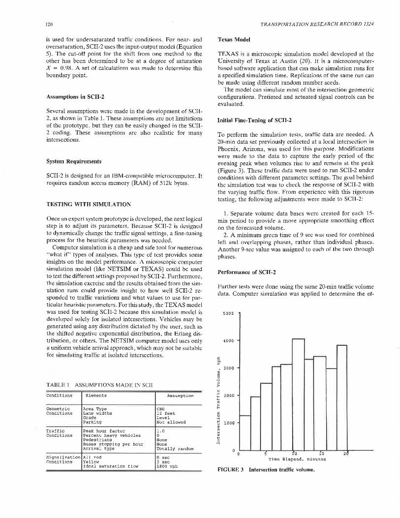
To perform the simulation tests, traffic data are needed. A 20-min data set previously collected at a local intersection in Phoenix, Arizona, was used for this purpose. Modifications were made to the data to capture the early period of the evening peak when volumes rise to and remain at the peak (Figure 3). These traffic data were used to run SCII-2 under conditions with different parameter settings. The goal behind the simulation test was to check the response of SCII-2 with the varying traffic flow. From experience with this rigorous testing, the following adjustments were made to SCII-2:
1. Separate volume data bases were created for each 15-min period to provide a more appropriate smoothing effect on the forecasted volume.
2. A minimum green time of 9 sec was used for combined left and overlapping phases, rather than individual phases. Another 9-sec value was assigned to each of the two through phases.
Performance of SCII-2
Further tests were done using the same 20-min traffic volume data. Computer simulation was applied to determine the ef-
5000
4000 - .....---
-.<:: 0.
.....---.._... >
oJ 300 0
~,-----
'----
5 :J .... 0 ~
:>
" .... 2000 ... -...
'" '" E-<
c: 0 ,___ .... ...,
1 00 0 " OJ Ill
'" OJ ..., c: H
0 0 5 ro !5 2
Time Elapsed, minutes
FIGURE 3 Intersection traffic volume.

Elahi et al.
fectiveness of SCII-2 performance compared with the performances of conventional (pretimed and actuated) controllers.
First, cycle length and splits were determined for a fourphase pretimed operation (dual left, through/right, dual left, and through/right) using basic principles. The cycle length was found to be 110 sec (splits of 19, 38, 10, and 43 sec; yellow of 3 sec; all-red of 1 sec). Therefore, the first run of TEXAS covered a period of 110 sec. The second run covered a period of 110 to 220 sec. Similarly, runs were made for the whole test period with the corresponding traffic volumes. For each run, five replications were made with different random number seeds. Each replication was made for a period of 35 min, with 5 min of warm-up and 30 min of simulation. Traffic delays were noted and the mean was calculated for each run.
Similarly, an actuated setting was simulated with the TEXAS model, using the timing scheme for pretimed operation as the maximum green interval of the actuated operation. Stopped delay over the 20-min period was noted.
A similar approach was adopted for simulating signal settings suggested by SCII-2. Stopped delays were noted for entire 20-min period.
Figure 4 compares pretimed, actuated, and SCII-2 performance for the test case. Comparison between the pretimed controller and SCII-2 indicates that initially the pretimed controller produced a delay of 38 sec/veh, and SCII-2 produced a delay of 10 sec/veh. As the traffic volume gradually increased, the delay increased in both cases. The pretimed controller produced a maximum delay of 63 sec/veh, and SCil-2 produced a maximum delay of 45 sec/veh. SCII-2 was found to perform better than the pretimed controller over the entire 20-min interval.
Comparison between SCII-2 and a full-actuated controller shows that initially SCII-2 performed much better than the actuated controller. With the increase of traffic volume, SCil-2 performance became equivalent to the actuated controller performance.
..c: ~ ..... u 11> en
80
60
20
Pre timed
• · · · • · · · · Actuated
- - - - - - SCII-2
,..--1 r--l : I
. l i :·: .... : 1 I : I
,...; .. !. ... ,.... : I I L..-{ : I I I •I I {' • •• :J
- .J I .--: .... .J
:····· I --i.----- ... r--r--~
0 10 15 20
Time Elapsed, minutes
FIGURE 4 Comparison of intersection delays for three controller operations.
121
CONCLUSIONS
The objective of this research was to modify the initial SCII-1 prototype. The prototype was expanded to operate in both the conventional and adaptive control modes of signal operation. Modifications were made to SCII-1 to operate under different intersection geometric conditions and to determine the appropriate phasing pattern. Most of the SCII-1 heuristics were revised. Queue length was used as a performance measure in addition to stopped delay. Finally, simulations were made to gain confidence in the prototype.
Computer simulation was found to be an effective tool for testing the prototype. The tests using the TEXAS simulation model provided an initial validation of the prototype. It demonstrated the potential of this prototype to reduce delay at isolated intersections using one data set. Rigorous testing of this prototype is required under different scenarios using both simulation and field tests, with further refinement of the prototype as needed in the course of testing.
REFERENCES
1. P. J . Tarnoff and P. S. Parsonson. NCHRP Report 233: Selecting Traffic Signal Control at Individual Intersections. TRB, National Research Council , Washington, D.C., 1981.
2. K. M. Gou!, K. Moffitt, T. O'Leary , and A. E. Radwan. The Art of Validating Expert Systems: The Project SCI/ Experience. Technical Report 87-2. Decision Systems Research Center, College of Business, Arizona State University, Tempe.
3. K. M. Goul, A. E . Radwan , T. O'Leary , and K. Moffitt. Project SCI/: A Real-Time Knowledge-Based Expert System for Traffic Control. Decision Systems Research Center, College of Business, Arizona State University, Tempe.
4. K. M. Goul, T. J. O'Leary, and A. E. Radwan. Expert Systems for Traffic Signal Control. Proc., Microcomputer Applications in Transportation-II International Conference. ASCE, New York, 1987, pp. 629-638.
5. A. E. Radwan , K. M. Goul, T. J. O 'Leary , and K. E. Moffitt. A Verification Approach for Knowledge-Based Systems. Transportation Research, Vol. 23A, No. 4, 1989.
6. F. V. Webster. Traffic Signal Sellings. Road Research Technical Paper 39, Road Research Laboratory, Her Majesty's Stationery Office, London, England, 1958.
7. Special Report 209: Highway Capacity Manual. TRB, National Research Council, Washington, D.C., 1985.
8. W. B. Cronje. Analysis of Existing Formulas for Delay, Overflow , and Stops. In Transportation Research Record 905, TRB, National Research Council, Washington, D.C., 1983.
9. G . F. Newell. Approximation Methods for Queues with Application to the Fixed-Cycle Traffic Light. SIAM Review, Vol. 7, 1965 .
10. A. 1. Miller. Settings for Fixed-Cycle Traffic Signals. Operational Research Quarterly, Vol. 14, 1963 .
11. A. J. Miller. The Capacity of Signalized Intersections in Australia. ARRB Bulletin 3, Australian Road Research Board, 1968.
12. G. F. Newell. Applications of Queuing Th eory, 2nd ed. Chapman and Hall, London, England, 1982, pp . 287 - 300.
13. F. Hayes-Roth , D . A . Waterman, and D. B. Lena!. Building Expert Systems. Addison-Wesley Publishing Company , Inc., Reading, Mass., 1983.
14. A.G. R. Bullen, N. Hummon, T. Bryer, and R . Nekmat. EVIPAS: A Computer Model for the Optimal Design of a Vehicle-Actuated Traffic Signal. In Transportation Research Record 1114, TRB, National Research Council , Washington, D .C., 1987.
15. C. Zozaya-Gorostiza and C. Hendrickson. Expert System for Traffic Signal Setting Assistance. Journal of Transportation Engineering, Vol. 113 , No . 3, March 1987.
16. N. H. Gartner. OPAC: A Demand-Responsive Strategy for Traffic

122
Signal Control. In Transportation Research Record 906, TRB, · National Research Council, Washington, D.C., 1983.
17. Evaluation of the Optimized Policies for Adaptive Control Strategy. Report FHWA-RD-89-135. FHWA, U.S. Department of Transportation, 1989.
18. F. Lin, D. Cooke, and S. Vijayakumar. Use of Predicted Vehicle Arrival Information for Adaptive Signal Control-An Assessment. In Transportation Research Record 1112, TRB, National Research Council, Washington, D.C., 1987.
19. F. Lin, N. Wang, and S. Vijayakumar. Development of an In-
TRANSPORTATION RESEARCH RECORD 1324
telligent Adaptive Control Logic. Presented at the Engineering Foundation Conference on Management and Control of Urban Traffic, New Hampshire, June 1987.
20. C. E. Lee, T. W. Rioux, and C.R. Copeland. The TEXAS Model for Intersection Traffic-Development. Research Report 184-1. Center for Highway Research, The University of Texas, Austin, 1977.
Publication of this paper sponsored by Committee on Traffic Signal Systems.