kreis ludwigsburg ·west germany - vintage sno 190r... · avec son disque de protection en...
TRANSCRIPT

HIRTH MOTOREN 1--<Ei 7141 BENNINGEN! NECKAR · KRE I S LUDWIGSBURG ·WEST GERMANY
Instructions for the Assembly and Disassembly of Engine
190R lntructions pour le Montage et D6montage du Moteur

Technical data
Engine output
Direction of rotation
Bore
Stroke
Cylinder displacement
Point gap
Ignition timing
Recommended spark plug for high load
Spark plug gap
Ignition unit
Hirth Type 190 R
16 DIN H.P. at 5000 R.P.M.
Counter-clockwise in view of Power Take-Off Shaft.
75 mm. 2.95 ins.
68 mm. 2.67 ins.
300 ccm. 18.30 cu. ins.
0,4 ± 0,05 mm (0.0157 ± 0.002 ins.)
to be set when engine is not running: 7~ before TDC equal to 0,50 mm (0.020 ins.)
advances automatically when engine is running: 25 before TDC equal to 3,95 mm (0.156 ins.)
Champion UK 10 or Bosch M 225 T 1 or Bosch MV 225 T 1
0,4-0,5 mm (0.0157-0.020 ins.)
Bosch dynamo magneto ignition with advance timing
Caracteristlques techniques - Hirth Type 190 R
Puissance
Sens de rotation
Alesage
Course
Cylindree
Ecartement aux vis platinees
Reglage d'allumage
Bougie recommandee pour charge forte
Ecartement des electrodes
Allumage
16 PS DIN a 5000 t/m
a gauche en regardant l 'arbre moteur
75 mm (2,95 pes)
68 mm (2,67 pes)
300 ems {18,30 pes cu)
0,4 ± 0,05 mm (0,0157 ± 0,002 pes)
doit litre ajuste quand me moteur ne marche pas: 7 avant le PMH, egal 0,50 mm (0.020 pes)
avancant automatiquement quand le moteur marche : 25° avant le PMH egal 3,95 mm (0.156 pes)
Champion UK 10 ou Bosch M 225 T 1 ou encore Bosch MV 225 T 1
0,4-0,5 mm (0,0157-0,020 pes)
volant magnetique Bosch avec bobine lumil~re

Dismantling the engine - 190 R
1. Dismount engine from vehicle and remove attaching parts. Remove electric starter if one has been installed.
2. Mount engine on bench vice by using mounting angle w 115.
Fan housing
3. Remove fan housing complete with recoil-starter by removing the socket head cap screws.
Fan Wheel
4. Screw on holding device for fan wheel W 116 with the 2 cylindrical head screws belonging to it, to crankcase. Remove catch piece with security plate for recoi l starter by loosening the 3 cylindrical head screws with ell ern type wrench 5 01 N 911. Remove cover plate which is installed behind it.
5. Loosen hex. nut, which is used to fasten the fan wheel, with a socket wrench (wrench size 24 mm). Apply fan wheel puller with the 3 hexagon bolts to the 3 threads of the fan wheel, tapped for this purpose. Lift off fan wheel by turning thrust screw of puller to the right. Remove holding device in order to allow for the removal of the fan wheel. (Illustration 1)
Ignition
6. Loosen hex. cutting screw by means of which the ignition wire clip is fastened to cylinder head. Unwind spark plug hood from ignition wire. Slip off ignition wire clip with connecting wire piece from ignition wire. If necessary, unscrew light, ground and shortcircuit wires from connector.
Demontage du moteur - 190 R
1. Depose du moteur - depose des accessoires eventuellement, depose du demarreur electrique.
2. Fixer le gabarit W 115 au moteur et le serrer dans un etau.
Capot du ventilateur.
3. Demonter le capot du vent ilateur avec son lanceur a main incorpore en devissant les boulons cylindriques.
Ventilateur
4. Visser le systeme de blocage du ventilateur W 116 avec ses deux boulons cylindriques sur le demi-carter. Retirer le dispositif d'entrainemant du lanceur a main avec son disque de protection en devissant les trois boulons a t~te cylindrique au moyen de Ia cle male a 6 pans 5 01 N 911. En lever egalement Ia tole de protection qui se trouve derriere.
5. Devisser l 'ecrou a 6 pans qui fixe le ventilateur au moyen d'une cle a tube (24 mm) ; puis visser l 'extracteur les trois boulons a 6 pans dans les trois prevus a cet effet au ventilateur. Retirer le venti lateur en tournant Ia vis de pression de l'extracteur dans le sens des aiguilles d'une montre. Devisser le dispositif de blocage afin de pouvoir retirer le ventilateur. (Figure 1)
(1;
Allumage
6. Devisscr le boulon a 6 pans qui fixe l'agrafe du fil de bougie a Ia culasse. Retirer le chapeau du fil de Ia bougie. Retirer Ia gaine, ainsi que le caoutchouc passe-cable du fil de bougie. Si necessaire, debrancher le fil d 'eclairage, le fil de masse et le fil du coupe circuit au domino.

7. Remove armature plate which is fastened with 3 cylindrical head screws. Spread a bit of oil on rubber socket for ignit ion wire on crankcase, through which the cables are run, in order to remove cable with armature plate more easily.
Cylinder
8. Remove air guide cap with profile rubber.
9. Remove cylinder head and gasket by loosening the 4 hex. nuts with 13 mm socket wrench. lift off cylinder.
Piston
10. Remove piston pin spring rings by using interior snapring pliers. Push out piston pin with drift pin W 39 4. If necessary, apply light hammer strokes. While doing it, support piston with hand and then remove piston.
11. Slide needle cage from small-end hold of connecting rod. It is suggested that it be mounted on piston pin, for safekeeping.
Radial Oil Seal Rings
12. Turn engine by 180 and remount on bench vice.
13. Using a pointed object, held at an angle, strike through seal ring frame. Exercise great care in order not to damage the bearing which is located behind the frame. Insert a hook through this hole and pull out seal ring.
Crankcase
14. Using external snap ring pliers remove crankshaft snap ring. Using ellern type wrench 5 DIN 911 loosen the 6 crankcase bolts.
2
7. Deposer le stator fixe par trois vis cylindriques, mettre une goutte d'huile sur le caoutchouc passe-cable ce qui facil itera le passage des cables du stator.
Cylindre
8. Enlever le capot guide d'air ainsi que son joint en caoutchouc.
9. Enlever Ia culasse avec son joint apres avoir devisse ses 4 ecrous au moyen de Ia cle de 13 mm. Enlever le cylindre.
Piston
10. Retirer les circlips de l'axe du piston au moyen d'unc pince a circlips interieurs. Retirer l 'axe du piston au moyen de Ia broche W 39/4. Si necessaire, maintenir Ia piston d'une main et faciliter son extraction en donnant des petits coups de marteau. Enlever le Piston.
11. Enlever le roulement a aiguilles d l'oeil du pied de bielle. Pour plus de sOrete, il est preferable de le poser tout de suite surl'axe du piston.
Bagues d'etancheite Simmer
12. Desserrer l'etau, faire tourner le moteur de 180 degres et resserrer l'etau.
13. A l'aide d'un burin donner des coups en oblique sur le joint Simmer en faisant bien attention de ne pas endommager le roulement a billes qui se trouve derriere. A l'aide d'un crochet passe dans Ia fente retirer le joint Simmer.
Le carter
14. Enlever le circlips du vilebrequin au moyen d'une pinr:e a circlips exterieurs. Devisser les six boulons du carter au moyen de Ia cle male a 6 pans 5 DIN 911.
(2)

15. Release engine from bench vice and unscrew mounting angle W 115.
16. Place engine fan side down on 2 logs W 110. Stick thrust piece W 105/ 4 into groove of crankshaft. Push one of the angular plates W 10515 across the tie rod of the crankcase, and screw the other angular plate W 105/ 5 into the base-cap thread of the crankcase bottom. Slide in drawing-off plate W 105 from below and fasten it with 4 hex. nuts to the angular plates By turning the thrust screw on drawing-off plate to the right pull off crankcase flange. Unscrew device from crankcase. (2)
Crankshaft
17. Remove the crankshaft from the crankcase in the following manner: evenly heat the crankcase on its ignition side to approximately 212 degrees Fahrenheit but not
above 285 degrees (100-140 degrees Centigrade). perhaps by using a soldering lamp. Then hold the crankcase and the crankshaft as shown in the illustration. Using a rubber mallet knock out the crankshaft with gentle strokes. Make sure that you hold the crankshaft as fi rmly as you can. (4)
18. Using a bolt and a hammer knock out the seal ring from the inside of the crancase.
Ball bearing
19. Remove the snap ring from the inside of the crankcase flange with snap ring pliers. The flange should
15. Desserrer l 'etau pour enlever le moteur et devisser le gabarit W 115.
16. Placer le moteur cote ventilateur sur les deux pieces de bois W 110. lntroduire Ia piece d'appui W 105/ 4 dans le creux de l 'arbre du vilebrequin, monter Ia plaque laterale W 105/ 5 en passant les trous sur les deux goujons du demi-carter. Monter Ia 2e plaque en se servant des trous et boulons de fexation du socle du moteur. Passer Ia plaque entrale en dessous des corniiHes des plaques laterales, Ia fixer au moyen des 4 rondelles et ecrous a 6 pans.
Faire tourner Ia vis de pression dans le sens des aiguilles d'une montre et separer les moities du carter (2)
Vilebrequin
17. Sortir le vilebrequin du carter en procedant de Ia maniere suivante: chauffer le carter cote volant magnetique de maniere reguliere, en se servant, par
(3)
exemple, d'un chalumeau, le porter a une temperature de 212 degres F environ (100 degres C) maximum; 285 degres F (140 degres C). Tenir, ensuite, le carter et le vi lebrequin comme indique sur Ia figure 4 et donner des petits coups sur le vi lebrequin avec un maillet en caoutchouc pour le faire sortir. Attention: bien Ienir le vilebrequin pendant tout ce processus.
18. Enlever le joint Simmer de l' interieur du carter au moyen d'un marteau et d' une broche.
Roulement a billes
19. Retirer le circlips de l ' interieur du flasque du carter au moyen d'une pince a circlips. Chauffer le flasque
3

I ' _/ ~
be heated (see paragraph 17, above) to permit the removal of the ball bearing by pushing it out with the handle of the hammer.
20. Remove grooved ball bearing on ignition side from crankshaft with bearing puller W 107. (5)
21. Wash engine parts in cleaning solvent. Carefully remove any remains of sealing material from sealing surfaces.
22. Replace defective parts.
4
(4)
avec un chalumeau comme decrit ci-dessus (cf. paragraphe 17). Avec le manche d'un marteau, pousser le roulemant a billes vers l 'exterieur.
20. Enlever le roulement cote volant magnetique a l'aide de l'extracteur W 107. (5)
21 . Nettoyer toutes les pieces a !'essence. Enlever soigneusement les restes de joints ou de pate d'etancheite sur Ia surface des joints.
22. Toutes les pieces endommagees doivent etre remplacees.

Assembling of engine - 190 R
Ball Bearing
1. Install snap ring on the P.T.O. side in the crankcase flange. Heat flange to 212 degrees but not above 285 degrees (100-140 degrees centigrade). Insert ball bearing until it catches the stop-pin of the snap ring. Mount second snap ring.
2. Lock crankcase flange on mounting angle W 115 and mount on bench vice.
Crankshaft
3. Insert the P.T.O. side of the crankshaft, through the bearing, as shown in illustration 6.
Screw on the mounting bolt of the feeding-in tool W 112 to the internal thread of the crankshaft. Pull the feeding-in tool over it until it reaches the ball bearing. Then back up once again as far as necessary in order to stick the pin through the feeding-in tool and the mounting bolt. By means of the two lever arms of the feeding-in tool pull in the cranshaft to th'3 end of the bore of the device. Reset the pin into the pinhole, in the direction of the housing. Repeat the feeding-in procedure until the crankshaft reaches the ball bearing.
4. Mount the snap ring on the crankshaft.
5. By means of the feeding-In tool W 112 and the pressure plate W 37 18, press in the seal ring on the end of the shaft, with the oil seal lip pointing inward. (The feeding-in procedure is as described in paragraph 3,
Remontage du moteur- 190 R
Roulements
1. Remonter le circlips cote joint Simmer dans Ia bride du demi -carter. Chauffer le demi-carter a 212 degres F environ (100 degres C). Ne pas depasser Ia temperature de 285 degr6s F (140 degres C). Monter le roulement dans son logement jusqu'a ce qu'il vienne buter contre le circlips ; monter le deuxieme circlips.
2. Visser le demi-carter sur le gabarit W 115 et serrer ce dernier dans l 'etau.
Villebrequin
3. Passer le bout d'arbre cote prise de force par Ia bague intlnieure du roulement a billes comme indique figure 6.
(6)
Visser l'appareil de montage W 112 dans le pas de vis de l'arbre du vile-brequin. Glisser l 'appareil de montage sur l 'arbre jusqu'a ce qu'il vienna buter contre le roulement. Puis revenir en arriere de fa~on a pouvoir passer Ia cheville dans le trou de l 'appareil de montage et celui correspondant de l'axe. A l'aide des deux leviers int roduire le vilebrequin j usqu'a fin de course de l'appareil, enlever Ia cheville Ia replacer dans le trou suivant cote carter. Continuer le processus de montage jusqu'a ce que le vilebrequin vienne buter contra le roulement a billes.
4. Mettre le circlips dans son logement sur le bout d'arbre du vilebrequin.
5. Au moyen de l 'appareil de montage W 112 et de Ia rondelle d'appui W 37t 8. Monter le joint Simmer cote prise de force, Ia levre d'etancheite tournee vers l'mterieur (suivre le processus indique au paragraphe 3).
5

above). By oiling its external diameter and its oil seal lip prior to the feeding-in, the seal ring will be much more easily mounted. (7)
Crankcase
6
6. Mount crankcase flange, turned by 180 degrees, on bench vice.
7. Spread evenly sealing compound over sealing are~\
of crankcase f lange.
8. Heat crankcase halfmember, ignition side, to 212 degrees but not more than 285 degrees (100 to 140 degrees centigrade), and mount on flange. Pay close attention to fitting pins. Install ball bearing on crankshaft and with device W 112 pull it into the end of tho shaft. Feed-in the bearing as described in paragraph 3, above.
Bien huiler Ia portee extrerieure ainsi que Ia levre d·etanchldte. Le montage en sera facilite. (7)
(i )
Carter
6. Faire tourner le demi-carter de 180 degres et resserrer le gabarit dans l'etau.
7. Enduire le joint du carter d'une solution d'etancheite sur toute sa surface.
8. Chauffer le demi-carter a 212 degres F environ {100 degres C). Ne pas depasser Ia temperature de 285 degres F {140 degres C). Le mettre en place sur le demi-carter oppose en veillant aux goujons-guides. Mettre le roulement sur l'arbre et a l 'aide de l 'appareil de montage W 112 pousser le roulement jusqu'a Ia
collerette du vilebrequin. Monter le roulement a billes suivant le processus decrit au paragraphe 3 ci-dessus.
(8)
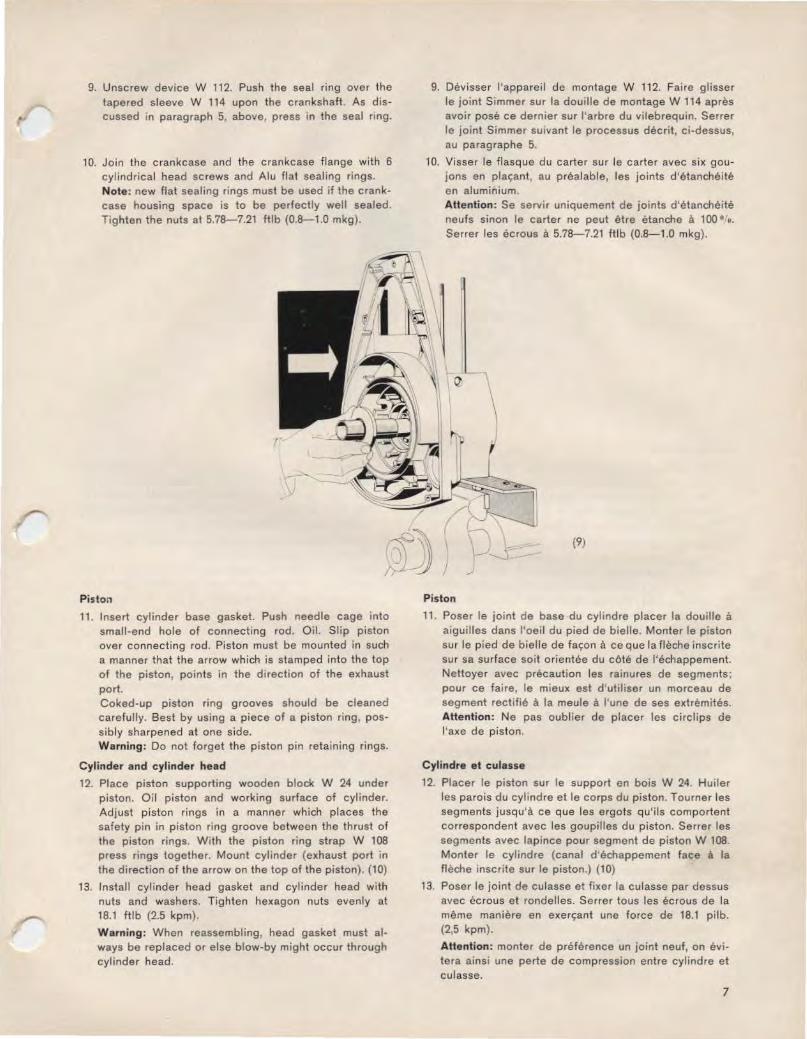
9. Unscrew device W 112. Push the seal ring over the tapered sleeve W 114 upon the crankshaft. As discussed in paragraph 5, above, press in the seal ring.
10. Join the crankcase and the crankcase f lange with 6 cylindrical head screws and Alu flat sealing rings. Note: new flat sealing rings must be used if the crankcase housing space is to be perfectly well sealed. Tighten the nuts at 5.78-7.21 ftlb (0.8-1.0 mkg).
Piston
11. Insert cylinder base gasket. Push needle cage into small-end hole of connecting rod. Oil. Slip piston over connecting rod. Piston must be mounted in such a manner that the arrow which is stamped into the top of the piston, points in the direction of the exhaust port. Coked-up piston ring grooves should be cleaned carefully. Best by using a piece of a piston ring, possibly sharpened at one side. Warning: Do not forget the piston pin retaining rings.
Cyl inder and cylinder head
12. Place piston supporting wooden block W 24 under piston. Oil piston and working surface of cylinder. Adjust piston rings in a manner which places the safety pin in piston ring groove between the thrust of the piston rings. With the piston ring strap W 108 press rings together. Mount cylinder (exhaust port in the direction of the arrow on the lop of the piston). (10)
13. Install cylinder head gasket and cylinder head with nuts and washers. Tighten hexagon nuts evenly at 18.1 ftlb (2.5 kpm).
Warning: When reassembling, head gasket must always be replaced or else blow-by might occur through cylinder head.
9. Devisser l'appareil de montage W 112. Faire glisser le joint Simmer sur Ia douille de montage W 114 apres avoir pose ce dernier sur l 'arbre du vilebrequin. Serrer le joint Simmer SUivant le processus decril, ci-dessus, au paragraphe 5.
10. Visser le flasquo du carter sur le carter avec six goujons en plac;ant, au prealable, les joints d'6tancheite en aluminium. AHention : Se servir uniquement de joints d'etancheite neufs sinon le carter ne peut etre etanche a 100 ••. Serrer les ecrous a 5.78-7.21 ftlb (0.8-1.0 mkg).
\
(9)
Piston
11. Poser le joint de base du cylindre placer Ia douille a aiguilles dans l'oeil du pied de bielle. Monter le piston sur le pied de bielle de fac;on a ce que Ia fleche inscrite sur sa surface soit orientee du cOte de l'echappement. Nettoyer avec precaution les rainures de segments: pour ce faire, le mieux est d'utiliser un morceau de segment rectifie a Ia meule a l'une de ses extremites. Attention: Ne pas oublier de placer les circlips de l'axe de piston.
Cylindre et culasse
12. Placer le piston sur le support en bois W 24. Huiler les parois du cylindre et le corps du piston. Tourner les segments jusqu'a ce que les ergots qu'i ls comportent correspondent avec les goupilles du piston. Serrer les segments avec lapince pour segment de piston W 108. Monter le cylindre (canal d'echappemenl face a Ia fleche inscrite sur le piston.) (1 0)
13. Poser le joint de culasse el fixer Ia culasse par dessus avec ecrous et rondelles. Serrer tous les ecrous de Ia marne maniere en exerc;ant une force de 18.1 pilb. (2,5 kpm).
AHention : monter de preference un joint neuf, on evitera ainsi une perle de compression entre cylindre et culasse.
7

Electric Wiring
14. Pull a insulating hose piece over the ignition wire in order to prevent a short-circuiting with the housing. The four wires (brown: ground ; yellow: light ; black: short circuit) should also be placed into a insulating hose to faci litate their handling.
15. Spread a drop of oil on rubber socket for ignition wire in crankcase housing, to pull wire through more easily. Push armature plate over crankshaft. Pull the 4 wires through the smaller hole of the rubber socket and the ignition wire through the larger hole. The cables should be pulled in until the armature plate rests on the fitting in place of the crankcase.
Armature Plate
16. Slightly tighten armature plate with three cylindrical head screws, toothed washers and flat washers, whi le making sure that the centre of the three oblong holes in the armature plate is aligned with the cylindrical head screws.
17. AHix fan wheel to taper such that the g rooving 10 the fan wheel is aligned with the grooving in the crankshaft. Push fitting key into groove.
Adjusting the distance of circuit breaker
18. Place fan wheel with keyway pointing upward. In this position, the circuit breaker is fully opened. Adjust distance of circuit-breaker to 0.016" (0.4 mm). First loosen slightly the securing bolt of 0.016" (0.4 mm) between the contacts. With screwdriver adjust to correct distance by using the cut-outs in the armature plate and the contact plate. Then tighten securing bolt of contact plate. (11)
8
(10)
Installation electrique
14. Passer une tuyau isolante sur le fil de bougie afin d'eviter les courts-circuits avec le carter. Afin de faciliter leur maniement, passer egalement les quatre fils electriques (brun: masse; jaune : alimentation ; noir: rupteur) po.r une tuyau isolante.
15. Huiler legerement le caoutchouc passe cable cela facilitera le passage des cables. Passer le cable de bougie par le grand trou et les 4 autres par le petit trou. Tirer les cables jusqu'a ce que le plateau port einduits ait pris sa place dans son logement du carter.
Volant magnt! tique
16. A l'aide des trois vis a tete cylindrique, rondelles dentees et rondelles plates serrer legerement le plateau d'allumage. Veiller a ce que les trois trous longs soiont centres par rapport aux vis a tete cylindrique.
17. Placer le ventilateur sur Ia partie conique de l 'arbre de telle sorte que l 'evidement qu' il comporte corresponde a l 'evidement de l'arbre du vilebrequin. Mettre le resort d'ajustage en place.
Reglage des vis platinees
18. Tourner le ventilateur de maniere a ce que Ia rainure de clavette soit tournee vers le haut. Dans cette position le rupteur est ouvert. Regier l'ecart entre les vis platinees a 0.016" (0.4 mm). Pour ce faire desserrer legerement Ia vis de fixation du porte-contacts. Mett re uno cale de 0.016" (0.4 mm) entre les contacts. Au moyen d'un tournevis passe dans l'ouverture reservee a cet effet, regler Ia distance entre plaque d'induit et porte-contacts jusqu'a ce qu'elle soit satisfaisante. Serrer ensuite Ia vis de fixation du porte-contacts. (11)

The Setting of proper ignition timing
19. On the circumference of the fan wheel two markers, in line form, are embossed. One line is marked "O.T.", wich stands for ,top dead centre". The other line, to the right of tho first one, at a distance of 49 mm. (25 degrees), is in the rotary direction of the fan wheel and represents the marker for ignition timing. Place ignition timing device no. 080.11 on a non-conducting surface of work bench and connect one wire clamp to ground (the housing) and the other wire clamp to the black shortcircuit wire. Turn fan wheel until the notation O.T. is aligned with the line mark on the housing and then turn on ignition timing device. Turn fan wheel approximately 45 degrees to the left (counter to the rotary direction). Once this position is reached, it is suggested that the centrifugal weight in the magneto ring, whose rim can be seen through the right-hand sight glass of the fan wheel, be pushed upward with the right index finger until it reaches the impact point. It should be held in that position. The fan wheel will then be turned to the right until the circuit breaker just starts to separate. (With battery operated ignition adjustment device, there will be a change in buzzer tone and control light brightens). In this position, the marking on the housing must be aligned with the second marking on the fan wheel. Should the circuit breaker separate before this aligned position is reached (advanced ignition), the armature plate must be turned to the right (rotary direction). Should the circuit breaker separate after the aligned position is reached (retarded ignition), the armature plate must be turned to the left (counter to the rotary direction). Should the armature plate have to be turned, the distance between the contacts will once again have to be verified (12). When the ignition position is properly set, tighten the three cylindrical head screws on the armature plate.
(11)
Reglage de l 'allumage
19. II y a deux traits sur le pourtour du rotor du ventilateur. On remarque a cote de l'un d'eux les lettres ,O.T." qui signifient ,point mort haut". l'autre trait, est a une distance de 49 mm sur Ia droite du premier (25 degres) dans le sens de Ia rotation du ventilateur. II represente Ia marque du point d'allumage. Placer l'appareil de controle d'anvance 080.11 sur l'etabli en veillant a ce qu'il soil bien isole. Mettre l'une des pinces-crocodile qu'il comporte a Ia masse (en Ia branchant sur le carter) et brancher !'autre sur l'extremite du fil du rupteur (fil noir). Tourner le ventilateur jusqu'a ce que les lettres ,,O.T. • correspondent avec le trait marque sur le carter. Mettre le contact a l'appareil de controle d'avance. Faire tourner le ventilateur d'environ 45° dans le sens contaire de celui des aiguilles d'une montre. Dans cette position, avec !'index de Ia main droite pousser vers le haut le poids centrifuge de l'aimant annulaire, dont on peut voir le bord par l'ouverture qui se trouve sur Ia partie droite du ventilateur, jusqu'a ce qu'il atteigne le point de contact. le maintenir dans cette position. puis, tourner le ventilateur dans le sens des aiguilles d'une montre jusqu'a ce que Je rupteur coupe le circuit. A ce moment-la Ia lampe temoin de l'appareil de contr61e d'avance s'allume et le buzzer emet un bruit different). Dans cette position le trait du carter doit se trouver dans l'alignement clu deuxieme trait qui se trouve sur le rotor du venti lateur. Si le rupteur coupe le circuit avant que ces deux traits ne se trouvent l'un en face de !'autre, (avance a l'allumage), tourner Ia plaque de l'induit dans le sens des aiguilles d'une montre. Si au contraire le rupteur coupe le circuit apres que les traits aient coincide (retard a l'allumage), tourner Ia plaque de l'induit dans le sens contraire de celui des aiguilles d'une montre. Si vous devez tourner a nouveau Ia plaque de l'induit, verifier d'abord l'ecart entre les vis platinees. (12). lorsque le reglage de l'allumage est correct, serrer les trois vis de fixation du plateau d'allumage.
9

20. Should a connector have been riveted to the crankcase, the earth, light and short circuit wires may be fastened to it. Pull insulating hose and cable clip over ignition wire. Mount spark plug hood, but make sure that the threaded rob is pushed firmly exactly in the centre of the wire until noticeable resistance is felt. Afterwards, screw in hood completely by slowly turning it clockwise. Insert spark plug into hood and put on cylinder head. By quickly turning fan wheel check ignition once more. Ignition spark must jump between electrodes of the spark plug. Screw in spark plug. Spark plug gap 0,016-0,020 ins.
21. Mount and tighten air guide plate, making certain that the profile rubber, which serves to seal off against the crankcase, is installed (if it is not, the air circulation for the cylinder will not function properly) , and that the ignition wire clip is held fast by the proper screw. Snap on spark plug hood.
22. Screw on holding device W 116 (See illustration 1, dismantling) and tighten fan wheel with washer and hexagon nut. Put on dust cover. Mount catch piece with security plate and tighten with the 3 hexagonal recess screws provided for that purpose. Unscrew the holding device. Mount fan housing with recoil-starter.
23. Test-run engine. After the first test possibly tighten cylinder head once more with torque wrench at 18.1 ftlb. (2,5 kpm).
24. Should the engine not be used for a longer time period, preserve the interior by means of the preservation funnel W 53. (Consult our preservation regulations).
10
(12)
20. Si le carter du vilebrequin comporte un attache-fils, y placer les fils de masse, le fil d'alimentation et le fil du rupteur (fil coupe-circuit). Passer le fil de bougie par Ia gaine de protection et Ia bride de fixation. Visser le chapeau de bougie. Pour ce faire, introduire Ia vis bien au centre jusqu'a ce que l'on sente une resistance, puis tourner le chapeau lentement vers Ia droite et visser a fond. Engager Ia bougie dans son chapeau. Placer le culot de Ia bougie sur Ia culasse. Controler une nouvelle fois l'allumage en faisant tourner rapidement le ventilatour. Une bonne etincelle doit se produire entre les deux electrodes. Tout d'abord Visser Ia bougie a Ia main dans Ia culasse, puis Ia bloquer a !'aide d'une cle et d'une broche. Pont d'allumage de Ia bougie: 0.016-0.020 pes.
21. Monter le capot guide d'air, bien s'assurer que le joint en caoutchouc moule qui sert a l'ajuster contre le carter du vi lebrequin est en place (sinon Ia circulation cl'air vers le cylindre ne se fera pas correctement.) Le fixer; ce faisant, serrer Ia bride de fixation du cable de bougie sous l'ecrou correspondant. Mettre le chapeau de boug1e sur Ia bougie.
22. Visser le dispositif de blocage du ventilateur W 116 (Voir Figure 1 Demontage). A !'aide de l'ecrou a six pans et de Ia rondelle serrer le rotor du ventilateur. Placer Ia tole pare-poussiere. Monter l'entraineur avec sa plaque de protection et le fixer a !'aide des trois ecrous fournis a cet effet. Devisser le dispositif de blocage du ventilateur. Monter le capot du ventilateur avec son lanceur a main.
23. Faire tourner le moteur a l'essai. Apres les premiers essais resserrer les ecrous de culasse au moyen de Ia cle dynamometrique a 18.1 pi. lb (2,5 kpm).
24. Si le moteur ne doit pas ~tre utilise avant longtemps le preserver contre Ia corrosion au moyen de l 'entonnoir special W 53 (voir nos conseils de protection anti-corrosif avant stockage).

Dismantling the recoil starter
1. Unscrew the starter from the fan wheel housing.
2. Grip the starter in a vice.
3. Remove the snap ring with snap ring pliers. Take out the lock washer which lies behind it.
4. Draw off the cage with rollers from the curved section.
5. Unscrew the cover plate which joins the rope guide bushing to the starter housing.
6. Pull out the handle with the rope guide bushing from the housing guide. Pull out the rope by the handle until the rope outlet port becomes aligned with the halfround recess in the ro;;e disc. Then feed the rope into the recess and loosen the tension of the coi l spring
in the rope disc by turning it to the right. Make certain that the rope disc is pressed against the starter housing, else it might jump out.
7. Place a screwdriver through the sight hole of the rope disc right behind the spiral spring (between the spring and the starter housing). Press the spiral spring against the rope disc and pull off the rope disc with the spiral spring from the moving pin. Take care that the spiral spring does not jump out. (14)
8. Uncoil the wire rope from the rope disc and pull it out. If the spiral spring is found in good condition, it should
Demontage du lanceur a main 1. Devisser le lanceur a main du capot du ventilateur.
2. Serrer le lanceur dans un etau.
3. Enlever l 'anneau retenue avec une pince a circlips. Oter Ia rondelle voilee qui se trouve derriere.
4. Extraire Ia cage a galets avec les galets, de Ia piece a camas.
5. Devisser Ia plaque de retenue qui fixe Ia douil le du guide-cable au capot du lanceur.
G. Sortir Ia poignee du cable de lancement avec son guide-cable, de son logement. Sortir le cable de Jancement en tirant sur Ia poignee jusqu'a ce que le trou de sortie de Ia corde soit dans l 'alignement de l 'encoche decoupee dans le disque d'enroulement de Ia
(13)
corde. Placer le cable dans l 'encoche du disque d'enroulement du cable et par une rotation a droite ce faisant appuyer le disque d'enroulement contre le capot du lanceur. si non il pourrait etre ejecte. (13)
7. lntroduire l 'extremite du tourne-vis par le regard du disque d'enroulement du cable et le faire passer derriere le ressort en spirale (entre le ressort et le capot du lanceur). Serrer le ressort contre le disque retirer !'ensemble disque et ressort de son pivot. Veiller Ace que le ressort en spirale ne se detende pas. (14)
8. Derouler le cable du disque d 'enroulement et le sortir. Si le ressort en spirale est en bon etat, le laisser
11

be left on the rope disc. A broken spiral spring should be carefully removed, start ing with the inside.
9. Wash all the components in c leaning solvent.
Assembling the recoil starter
1. If necessary, insert a new spiral spring into the rope disc. New spiral springs are secured with a wire, which prevents them from bursting open. This wire should not be removed before the spiral spring is inserted into the rope disc.
2. Should the spiral spring burst open, coil up spring as shown in the illustration 15.
12
sur le disque d 'enroulement. S' il est casse, le retirer avec precaution en commen~ant par le centre.
9. Bien nettoyer toutes les pieces a !'essence.
Montage du lanceur a main
1. Sj necessaire placer un nouveau ressort en spirale dans le disque d'enroulement du cable du lanceur. Les ressorts en spirale neufs sont retenus par un fil rle fer qui les emp~che de se detendre. Ne pas Oter ~e fil de fer avant d' inserer le ressort en spirale dans le disque d'enroulement du cable.
2. S' i l arrivait neanmoins que le ressort en spirale se detende brusquement, i l faudrait l'onrouler suivant Ia methode indiquee sur Ia figure 15.
- ·''\
' (' \~\
fflOVJ ~ il__J~ (15)

r
3. Assemble the handle. Push the end of the rope through the handle and the c lamp ring. The clamp ring is conical and the larger diameter must be at the top. Bend the end of the rope into a loop so that the end of the rope can be pushed back again half way through the handle. Then fit the clamp piece into the loop of the rope so that the rope lies in the grooves in the clamp piece until the clamp piece jams tight with the rope in the clamp ring.
4. Pull the rope through the rope guide bushing. Hold the hub of the rope disc upwards and push the free end of the rope from the right under the nose, so that the end of the rope protrudes about 0.4-0.6 ins. beyond the nose to the left. Bend the rope back over the nose by 180 and coil up 2 to 3 turns tightly in this direction. Observe the length of the rope, as discussed in paragraph 8.
5. Apply a thin coating of oil to the spiral spring. Cover the thread of the cam segment and of the moving pin in the starter housing with Molykote Paste G.
6. Insert once again the end of the rope into the halfround recess of the rope disc. (Consult paragraph 6 of the dismantling procedure). Push the rope disc with the spiral spring over the moving pin in the starter housing such that the bent end of the spiral spring points at the slot in the starter housing. Turn rope disc lightly back and forth until the end of the spring engages in the slot. Should the insertion of the end of the spring prove difficult, it is suggested that the spring be spread apart first by sticking 3 pins (nails) through the 3 borings in the rope disc and then by pushing the rope disc over the moving pin. After this is done, the pins may be removed and the rope disc should be turned to the righ t, counter to the rotary direction of the motor, until the end of the spring audibly snaps into place. To verify it, turn the rope disc to the left until the sight hole in the rope disc
3. Montage de Ia poignee. Pousser l 'extremite du dble dans Ia poignee et Ia bague de serrage. La bague de serrage est conique; Ia disposer de sorte que son diametre le plus grand soit tourne vers le haut. Former une boucle avec l 'extremite du cable et l 'cnfoncer dans Ia poignee jusqu'a Ia moitie de Ia longueur de celleci environ. Placer, ensuite, le cone de serrage dans Ia boucle du cable dans Ia bague de serrage.
4. Enfiler le cable d'acier dans Ia douille guide-cable. Tourner le butoir de Ia poulie vers le haut. lntroduire l'extremite libre du cable SOU$ le butoir par Ia droite, ot le faire gl isser dessous de maniere que l'extremite du dble depasse le butoir vers Ia gauche d'environ 0,4-0,6 pes. Recourber le cable sur le butoir en lui faisant decrire un angle de 180- et enrouler solidement 2 ou 3 fois dans ce sens. (Pendre garde a Ia longueur du cable com me indique au paragraphe 8)!
5. Huiler legeremet le ressort en spirale. Enduiro lc filetage de Ia piece de came et du pivot dans le boitier du lanceur, de pate Molykote G.
(16)
6. Replacer l 'extremite du cable dans le plat du disque d'enroulement. (Consulter le paragraphe 6 des instructions de d6montage). Placer le disque d'enroulement du cable avec son ressort en spirale sur le pivot qui se trouve dans le boitier du lanceur de sorte que l 'extremite recourbee du ressort en spirale coincide avec Ia fente qui se trouve dans le boitier du lanceur. Faire tourner lt~gerement le disque d'enroulement du cable dans un sans puis dans !'autre jusqu'a ce que l'extremite du ressort s'engage dans Ia fente. Si !'insertion de l 'extremite s'avere difficile, il est conseille de detendre tout d'abord Ia ressort en introduisant trois pointes (clous) par les trois trous du disque d'enroulement du cable et en poussant ensui te le disque d'enroulement sur le pivot. Cela etant fait, enlever les pointes et tourner le disque d'enroulement du cable dans le sens contraire de celui de Ia
13

becomes aligned with the rope outlet port on the housing. When this position has been attained, the slot in the housing in which the end of the rope is engaged becomes visible. A screwdriver, applied to the end of the spring, will show us whether the spring has snapped in tightly; if it has not, a bit of additional pressure wi ll do the trick.
7. Coil up the rope on the rope disc, 2 turns to the left Push the rope guide bushing into the housing.
8. Pull the rope out smoothly by the handle several times up to the stop (Do not let the handle snap back when the rope runs back). This ensures that the rope coi ls up properly. With the rope pulled fully out, the checking dimension of the rope guide bushing must have the following length to the stop face of the handle.
Wire rope 165 A 16: total length: 2475 mm. The checking measurement should not be longer than 1600 mm.
Wire rope 165 C 2: total length: 2680 mm. The checking measurement should not be longer than 1800 mm. Should the measured length of the rope turn out to be longer than the specified checking measurement, take out the handle with the rope guide bushing and, as discussed in paragraph 6 above, by turning the rope disc to the left, prestress by another full turn.
9. Smear both sides of the two washers and lock washer with Molykote.
10. Slide one washer over the journal. Push the roller cage over the journal with its open end so that the pin fitted on the curved section lies in the cut-out in
14
rotation du moteur (dans le sens des aiguilles d'une montre) jusqu'a ce que l 'extremite du ressort vienne s'enclencher a sa place. Pour verifier qu' il en est bien ainsi faire tourner le disque d'enroulement du cable dans le sens contraire du celui des aiguilles d'une montre jusqu'a ce que le regard du disque d'enroulement du cable se trouve place dans l'alignement de l'ouverture de sortie du cable pratiquee dans le boitier. Dans cette postion, Ia fente du boitier dans laquelle l 'extremit6 du cable se trouve engagee e::t 1isible. Avec un tournevis s'assurer si le ressort est bien enclenche ; si ce n'est pas que le cas il suffira d'exercer unc press1on plus forte.
7. Enrouler le cable sur le disque d'enroulement de deux tours. lnserer Ia douille guide-cable dans le boitier.
8. Tirer plusieurs fois fermement le cable d'acier jusqu'a Ia butee (ne pas laisser claquer Ia poignee au retour du cable). On obtient ainsi un enroulement irreprochable du cable d'acier. Lorsque le cable d'acier est completement tire, Ia cote de controle entre Ia douille guide-cable et Ia surface de butee de Ia poignee doit avoir Ia longueur suivante:
Cable 165 A 16: longueur totale: 2475 mm. La longueur lors de Ia mensuration de verification ne doit pas exceder 1600 mm.
Cable 165 C 2: longueur totale: 2680 mm. La longueur lors de Ia mensuration de verification ne doit pas exceder 1800 mm. Si Ia longueur du cable est superieure acelle indiquee, enlever Ia poignee et Ia douille guidecable et, comme il a eta indique au paragraphe 6 cidessus, en faisant tourner le disque d'enroulement dans le sens contraire des aiguilles d'une montre, remonter le ressort d'un tour.
9. Enduire les deux faces des 2 rondelles et de Ia rondelle voilee de pate molycote.
10. Pousser 1 rondelle sur le tourillon. Pousser Ia cage a galets par le c6te ouvert sur le tourillon, de sorte que le tenon a encoche fixe sur Ia piece a cames vienne

the roller cage. The cage has two cut-outs for left and right hand running, which are marked by a cast arrow. Use the cut-out whose arrow points in the direction of rotation of the curved section.
11. Fit the second washer. Fit one or two lock washers against the second washer so that the corrugations show to the outside. Fit the locking ring in the groove in the journal. When pulling out the starter rope. the cage must remain at rest until the pin hits the stop If the cage does no hit the pin, fit a second lock washer.
12. Insert 3 clamp rollers in the pockets in the cage with cold resistant grease (e.g. Aero Shell Grease 4 or Mobil Grease no. 22). Fit the c irclip. Insert the annular spring over the cage into the grooves for the clamp rollers.
Note: Clamp rollers, cage pockets and the running surface of the curved section must not be smeared with Molykote.
13. Pull out the rope with the handle and grease with cold resistant grease (See tlem 12 for grease).
14. Fasten starter to fan housing by paying attention to the following procedure: 3 screws which serve to fasten the starter should be inserted by hand such that the starter can still be easily moved. Pull out starting rope by the handle with one hand, and hold taut. This procedure permits the three rollers in the free-running operation to align themselves in the coupling piece. It is in this position that the 3 screws should be tightened. Then insert and tighten the remaining 3 screws.
s'appliquer dans l'evidement de Ia cage a galets. La cage a galets comporte 2 evidements pour Ia rotation a gauche et Ia rotation a droite, qui sont tous deux marques d'une fleche. Utiliser h~videment dont Ia fleche indique le sens de rotation de Ia piece a cames.
11. Placer Ia 2e rondelle. Placer 1 ou 2 rondelles voilees sur Ia 2e rondelle, de sorte que Ia face bombee des rondelles soit tournee vers l 'exterieur. lnserer l'anneau de retenue dans Ia fente du tourillon. Lorsqu'on lire le cable du lanceur, Ia cage doit rester immobile jusqu'a ce que Ia goupille butte. Si Ia cage ne butte pas contre Ia goupille, inserer Ia seconde rondelle voilee.
12. lntroduire 3 galets de serrage avec de Ia graisse stable au froid (par example Aero Shell Grease 4 ou Mobil Grease no. 22) dans les poches de Ia cage a galets de serrage.
Attention: Les galet s de serrage, les poches de Ia cage et Ia surface de roulement de Ia piece a cames ne doivent pas etre enduits de pate molycote.
13. Tirer le cable d'acier au niveau de Ia poignee et enduire de graisse stable au froid (graisse, voir paragraphe 12).
14. Monter le lanceur sur le capot guide d'air et proceder de Ia maniere suivante: serrer les trois vis a Ia main de maniere a ce que le lanceur ait du j eu. Tirer qualque peu Ia poignee de lancement; Ia maintenir pour obtenir le centrage des trois rouleaux d'entrainement dans l 'entraineur. Dans cette position serer les trois vis, puis monter et serrer les trois vis restantes.
15

Set of Special Tools for Complet Assembly and Disassembly of the HIRTH engine 190 A
Outillage Special pour le Montage et le Demontage complet de moteur HIRTH 190 A
pic-ture image
2
3
4
5
6
7 7
8
9
10
11
12
13
14
15
16
17
18
quantity quantile
descriptio n
2
2
Mounting angel gabarit pour le montage du moteur
Holding Device for Fanwheel disposi tif de blocagc du ventilateur
Fanwheel Puller R.H. Thread arrache venttlateur
Drift Pin for Piston pin broche de montage pour axe de piston
square pieces of wood support carre en bois
Bearing Puller extracteur pour roulements
set ; Putting in for Bearing Puller serie accessoire pour exiracteur. bague d'extraction
en deux parties
Pressure plate for installi ng Oil Seal Rondelle d'appui pour le montage des joints Simmer
Tapered Assembly Sleeve for Oil Seal douille de montage pour joints Simmer
Piston support support en bois pour piston
Piston Ring Compressor collier a segments
Piston Ri ng Extractor pince pour collier a segments
Cam acting device to draw Crankshaft into the crankcase: appareil de montage du vilebrequin dans le carter
Crankcase Separator dispositif de demontage des carter
Thrust piece piece d'appui de Ia vis de pression
Angular plate plaques laterales
Battery powered Ignition Timing Gauge appareil de reglage de l 'allumage
Special Oil Funnel for protecting of the engine entonnoir special pour t raitement anti corrosif avant
stockage
part numbt!r No . de commonde
w 115
w 116
w 113
w 39/4
w 110
w 107
w 107/ 15
w 37/8
w 114
w 24
w 108' 15
w 108
w 112
w 105
w 10514
w 105/ 5
080.11
w 53

('\ \
I
I ('I) - ,.... -
0 -CIO
