ks w series substations - library.e.abb.com · ks... w series substations transformer substations...
TRANSCRIPT
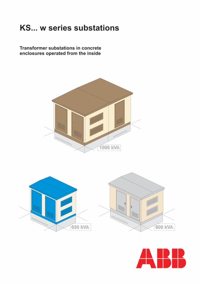
1000 kVA1000 kVA
800 kVA800 kVA630 kVA630 kVA
KS... w series substations
Transformer substations in concreteenclosures operated from the inside
ABB
3
Table of contents
1. Subject of the paper ...................................................................................................................... 4 2. Application of the substation........................................................................................................ 4 3. Technical specifications ............................................................................................................... 4
3.1. Substation building................................................................................................................ 5 3.1.1. KS 22-30w substation building specifications: ................................................................ 6 3.1.2. KS 25-36w substation building specifications: ................................................................ 6 3.1.3 Building supplementary data: ........................................................................................... 7
3.2. Equipment arrangement......................................................................................................... 7 3.3. Substation technical specifications........................................................................................ 8
3.3.1. Standards: ......................................................................................................................... 9 3.4. Medium-voltage switchgears................................................................................................. 9 3.5. Low-voltage switchboards .................................................................................................... 9 3.6. Transformers.......................................................................................................................... 9 3.7. Medium-voltage and low-voltage cable connections .......................................................... 19 3.8. Substation earthing ............................................................................................................. 10
4. Substation assembly and foundation ......................................................................................... 10 4.1. Substation foundation trench and installation of the substation.......................................... 11
5. Environmental protection ........................................................................................................... 11 6. Warranty ..................................................................................................................................... 11 7. Documentation acceptance ......................................................................................................... 12 8. Ordering a substation.................................................................................................................. 12 9. Substation transportation and hand-over .................................................................................... 12 10. KS 22-30 w substation - standard ..........................................................................................25-26 11. KS 25-36 w substation - standard............................. ..............................................................27-28 12. KS 25-36 w substation - with medium-voltage side measurement.........................................29-30 13. 2 KS 22-30 w substation - separate medium-voltage and low-voltage compartments...........31-32 14. 2 KS 25-36 w substation - two-transformer substation ............................... ...........................33-34 15. 2 KS 25-36 w substation - separate medium-voltage and low-voltage (power distribution company and clients) compartments .............................................................................. ............ 35
List of figures (appendices)
Fig. 01. Exterior style. Fig. 02. KS 22-30 w equipment placement Fig. 03. KS 22-30 w equipment placement Fig. 04. KS 25-36 w equipment placement Fig. 05. KS 25-36 w equipment placement Fig. 06. Cable bushings Fig. 07. KS...w joinery
4
1. Subject of the paper The subject of the paper are transformer substations operated from the inside, housed in reinforced concrete enclosures: • KS 22-30 w substation .............................. with transformer of up to 630 kVA • KS 25-36 w substation .............................. with transformer of up to 630 kVA • 2 KS 22-30 w substation ...................e.g..: • separated medium-voltage and low-voltage compartments • with transformer of up to 800 kVA • 2 KS 25-36 w substation ...................e.g.: • two-transformer substation • with transformer of up to 1000 kVA The substation is made as a complete, self-contained power device. It comprises a transformer, medium-voltage and low-voltage switchgear, a measurement circuit on the medium-voltage or low-voltage sides, cables and associated equipment; it’s a ready-to-use product to be placed directly in the desired location.
number of substation buildingstype of KS in the set-up
KS Compact transformer substation
substation building dimensions (dm)
w – operated from the inside
KS - wsubstation designation
2. Application of the substation The KS...w type transformer substations are designed to provide electrical power supply to public and industrial customers from medium-voltage networks of up 20 kV, and low-voltage networks of 400/230 V in TN-C systems.
3. Technical specifications The substation, depending on the building type, is designed for the following equipment: Building KS 22-30 w (→ page 25) medium-voltage switchgear: ............ option: with SF6 insulation - SafeRing or SafePlus • up to 3 bays (24 kV) option: with air insulation - UniSwitch (compact) • up to 3 bays (24 kV) low-voltage switchboard type RNTw ...... 1250 A 6 (10) transformer ............................up to 630 kVA
5
Building KS 25-36 w (→ pages 27, 29) medium-voltage switchgear: ............ option: with SF6 insulation - SafeRing or SafePlus • up to 5 bays (24 kV) option: with air insulation - traditional • up to 4 (3) bays of 17.5 kV (24 kV) option: with air insulation - UniSwitch (compact) • up to 5 bays of 24 kV low-voltage switchboard type RNTw ....... 1250 A transformer..............................up to 630 kVA Buildings 2 KS 22-30 w (→pages 31-35) Buildings 2 KS 25-36 w medium-voltage switchgear: ..................
transformer.............................up to 1000 kVA
up to 2 x 630 kVA
low-voltage RNTw type switchboard.... 1250 A
1600 A
3.1. Substation building The KS...w substation buildings are made of concrete using permanent moulds (walls and base are made of B35 type concrete, roof is made of B45 type concrete – walls are 10 cm thick).
The supporting constructions as well as fixing and transporting fittings are metallically joined with building reinforcement. All metal components of the building are hot-zinc-coated. Substation doors and ventilation grates are made of aluminium sheets and sections, and are painted with polyester powder paints (→ fig. 07, page 42). The door frame of the transformer room is equipped with protection railing hooks; the ventilation grates are equipped with insect screens. The building roof (→ page 16) is fitted with threaded transport sockets. The installation of equipment inside the KS...w is made through the doors as standard (also possible through the roof).
Die-cast concrete building (deformations and cracking of the building in the construction, transportation and operation processes
are eliminated)
Substation concrete components: building, base and roof
the UniSwitch, SafePlus, and the traditional air insulated type switchgears,allow free choice of configuration of medium-voltage bays
6
The building cable base is also the building foundation. The base of the building has a separate, non-leaking oil pit, preventing the transformer oil from permeation into the soil and the ground water. The medium-voltage and low-voltage cables are passed into the building base through P70 type cable bushings (30 pcs. – 10 per each base wall) or HD cable bushings (→ fig. 06). The substation building internal walls and roof are pained with white waterproof acrylic paints; the walls, base floor and substation building floor are mufti-layer painted with sealing paints. The external walls structural plaster finish and the roof are pained with sealing paints according to the RAL colour palette. The base trim and the roof are painted – from the outside – with sealing paints in the substation door colour (optionally, the base trim is finished with ceramic tiles). The standard substation external finish is shown in fig. 01.
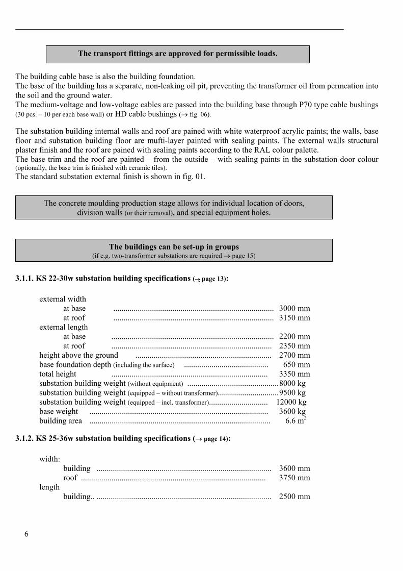
3.1.1. KS 22-30w substation building specifications (→ page 13):
external width at base ............................................................................... 3000 mm at roof ............................................................................... 3150 mm external length at base ................................................................................ 2200 mm at roof ............................................................................... 2350 mm height above the ground ................................................................... 2700 mm base foundation depth (including the surface) .......................................... 650 mm total height ............................................................................. 3350 mm substation building weight (without equipment) ............................................. 8000 kg substation building weight (equipped – without transformer).............................. 9500 kg substation building weight (equipped – incl. transformer)............................. 12000 kg base weight ........................................................................................ 3600 kg building area ......................................................................................... 6.6 m2
3.1.2. KS 25-36w substation building specifications (→ page 14):
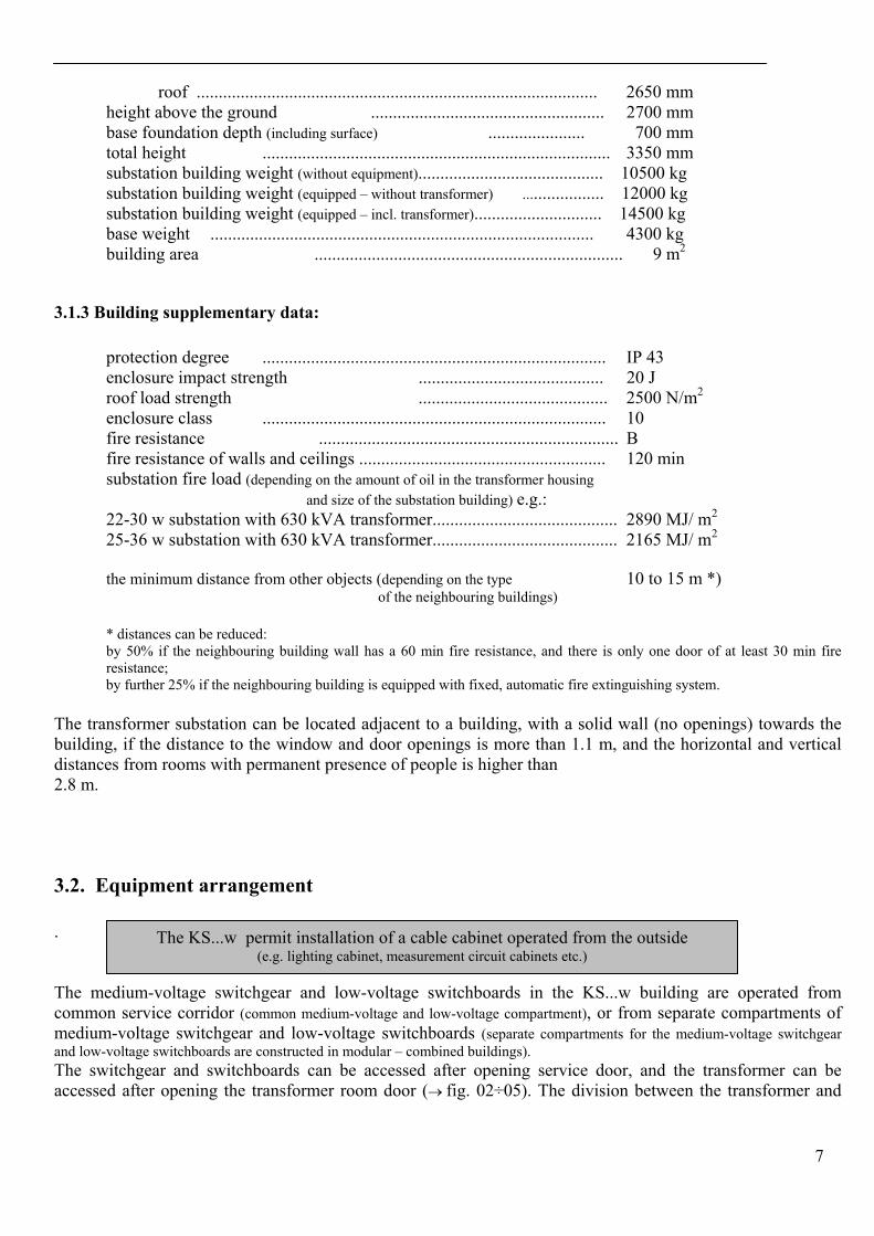
width: building ...................................................................................... 3600 mm roof ........................................................................................... 3750 mm
length building.. ...................................................................................... 2500 mm
The buildings can be set-up in groups (if e.g. two-transformer substations are required → page 15)
The transport fittings are approved for permissible loads.
The concrete moulding production stage allows for individual location of doors, division walls (or their removal), and special equipment holes.
7
roof ........................................................................................... 2650 mm
height above the ground ..................................................... 2700 mm base foundation depth (including surface) ...................... 700 mm total height ............................................................................... 3350 mm substation building weight (without equipment).......................................... 10500 kg substation building weight (equipped – without transformer) ................... 12000 kg substation building weight (equipped – incl. transformer)............................. 14500 kg base weight ....................................................................................... 4300 kg building area ...................................................................... 9 m2
3.1.3 Building supplementary data:
protection degree .............................................................................. IP 43 enclosure impact strength .......................................... 20 J roof load strength ........................................... 2500 N/m2
enclosure class .............................................................................. 10 fire resistance .................................................................... B fire resistance of walls and ceilings ........................................................ 120 min substation fire load (depending on the amount of oil in the transformer housing
and size of the substation building) e.g.:
22-30 w substation with 630 kVA transformer.......................................... 2890 MJ/ m2
25-36 w substation with 630 kVA transformer.......................................... 2165 MJ/ m2
the minimum distance from other objects (depending on the type 10 to 15 m *) of the neighbouring buildings)
* distances can be reduced: by 50% if the neighbouring building wall has a 60 min fire resistance, and there is only one door of at least 30 min fire resistance; by further 25% if the neighbouring building is equipped with fixed, automatic fire extinguishing system.
The transformer substation can be located adjacent to a building, with a solid wall (no openings) towards the building, if the distance to the window and door openings is more than 1.1 m, and the horizontal and vertical distances from rooms with permanent presence of people is higher than 2.8 m.
3.2. Equipment arrangement
.
The medium-voltage switchgear and low-voltage switchboards in the KS...w building are operated from common service corridor (common medium-voltage and low-voltage compartment), or from separate compartments of medium-voltage switchgear and low-voltage switchboards (separate compartments for the medium-voltage switchgear and low-voltage switchboards are constructed in modular – combined buildings). The switchgear and switchboards can be accessed after opening service door, and the transformer can be accessed after opening the transformer room door (→ fig. 02÷05). The division between the transformer and
The KS...w permit installation of a cable cabinet operated from the outside (e.g. lighting cabinet, measurement circuit cabinets etc.)
8
the medium-voltage switchgear and low-voltage switchboards service corridor is made of supplementary substation equipment, i.e. RNTw switchgear, cable duct and mounting panels.
3.3. Substation technical specifications The KS...w series transformer substations are type-tested at the Electrical Power Institute in Warsaw.
• transformer substations type: KS 22-30 w (up to 630 kVA) certificate no. 569 • transformer substations type: KS 25-36 w (up to 630 kVA) certificate no. 569 attestation no. 021/2002 • transformer substations type: KS 25-36 w (up to 1000 kVA) certificate no. 596
Substations are tested for:
• general requirements regarding construction and functionality • mechanical strength of the building against impacts and loads, • ingress protection, heat build-up inside the station building, • electric strength of insulation, • main circuit and earthing connections fault current load, • inspection and evaluation of internal arc fault effects.
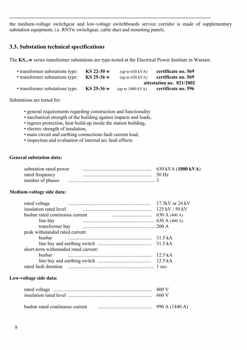
General substation data:
substation rated power ....................................................... 630 kVA (1000 kVA) rated frequency ....................................................... 50 Hz number of phases ...................................................................... 3
Medium-voltage side data:
rated voltage .................................................................. 17.5kV or 24 kV insulation rated level ....................................................... 125 kV / 50 kV busbar rated continuous current ................................ 630 A (400 A) line bay .......................................................... 630 A (400 A) transformer bay .......................................................... 200 A peak withstanded rated current: busbar ................................................................... 31.5 kA line bay and earthing switch ........................................... 31.5 kA short-term withstanded rated current: busbar ................................................................... 12.5 kA line bay and earthing switch ........................................... 12.5 kA rated fault duration ..................................................................... 1 sec.
Low-voltage side data:
rated voltage ............................................................................... 400 V insulation rated level ................................................................... 660 V busbar rated continuous current ............................................ 990 A (1440 A)
9
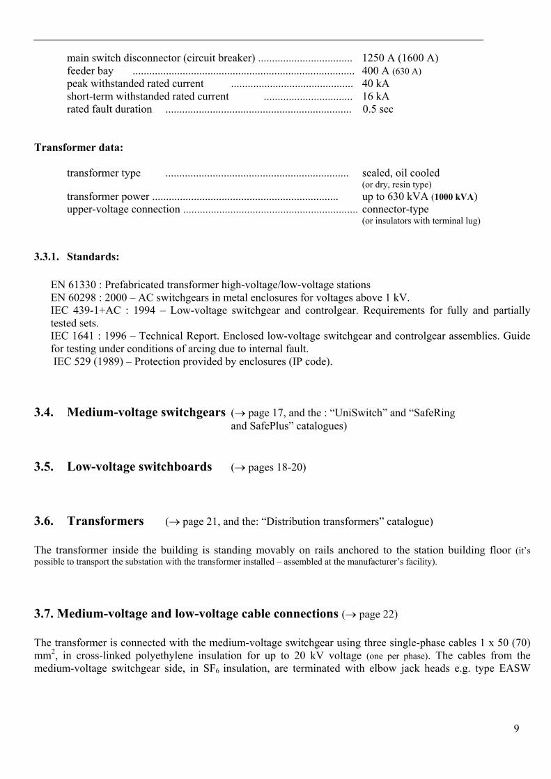
main switch disconnector (circuit breaker) .................................. 1250 A (1600 A) feeder bay ................................................................................ 400 A (630 A)
peak withstanded rated current ............................................ 40 kA short-term withstanded rated current ................................ 16 kA rated fault duration ................................................................... 0.5 sec
Transformer data:
transformer type .................................................................. sealed, oil cooled (or dry, resin type)
transformer power ................................................................... up to 630 kVA (1000 kVA) upper-voltage connection ............................................................... connector-type
(or insulators with terminal lug)
3.3.1. Standards:
EN 61330 : Prefabricated transformer high-voltage/low-voltage stations EN 60298 : 2000 – AC switchgears in metal enclosures for voltages above 1 kV. IEC 439-1+AC : 1994 – Low-voltage switchgear and controlgear. Requirements for fully and partially tested sets. IEC 1641 : 1996 – Technical Report. Enclosed low-voltage switchgear and controlgear assemblies. Guide for testing under conditions of arcing due to internal fault. IEC 529 (1989) – Protection provided by enclosures (IP code).
3.4. Medium-voltage switchgears (→ page 17, and the : “UniSwitch” and “SafeRing and SafePlus” catalogues)
3.5. Low-voltage switchboards (→ pages 18-20)
3.6. Transformers (→ page 21, and the: “Distribution transformers” catalogue)
The transformer inside the building is standing movably on rails anchored to the station building floor (it’s possible to transport the substation with the transformer installed – assembled at the manufacturer’s facility).
3.7. Medium-voltage and low-voltage cable connections (→ page 22) The transformer is connected with the medium-voltage switchgear using three single-phase cables 1 x 50 (70) mm2, in cross-linked polyethylene insulation for up to 20 kV voltage (one per phase). The cables from the medium-voltage switchgear side, in SF6 insulation, are terminated with elbow jack heads e.g. type EASW
10
20/250 (type of the head on the medium-voltage switchgear side is defined in the switchgear assembly and operation documentation). The medium-voltage switchgear side, in air insulation – are terminated with indoor heads e.g. TI 24 type. The cables for transformers fitted with connectors are terminated on the upper-voltage side with alternatively: elbow jack heads e.g. type EASW 20/250 or straight jack heads e.g. EASG 20/250. For the transformers with insulators, the cables on the upper-voltage side are terminated with indoor heads e.g. TI 24 type. The type of the heads can be chosen depending on how the cables are connected at the upper-voltage side of the transformer. The low-voltage cables of the RNTw switchboard are terminated with traditional KU 240 type cable terminals, and connected on the transformer side using e.g. PFISTERER type terminals or KU 240 type cable terminals. The transformer lower-voltage side terminals can be insulated with insulating covers. The cables entering the building base through the P70 bushings are sealed from outside with thermo-shrink tubes.
3.8. Substation earthing (→ page 23) The electric shock protection of the transformer substation is made with safety earthing. The low-voltage service earthings as well as the medium-voltage and low-voltage safety earthings are all connected to common earth.
Safety earthing: The substation equipment and structures are connected to the earthing busbar with the 1 x 50 mm2 cable in yellow and green insulation. The earthing busbar is connected through the measurement contact (1 → page 23) with external substation earthing (flat section 200mm2). The building reinforcement is used as a common, metallic connection of all the substation structure components.
RNTw switchboard service earthing: The PEN terminal of the RNTw switchgear is connected through the measurement contact (3) with the substation external earthing. Transformer service earthing: The transformer neutral point is connected through the measurement contact (2) with the substation external earthing. The measurement contact (2) is connected to the transformer neutral point using the 1 x 50 mm2 cable (1 x 120 mm2 or tinned flat-section 25 x 4 mm2 – acc. to the directives of Power Distribution Company) – with blue insulation. To facilitate substation earthing installation, flat-section FeZn 50 x 4 segments are provided to connect the earthing points no. 1, 2, and 3 with the circumferential earthing.
4. Substation assembly and foundation (→ page 24) The substation has been designed to be transportable to the construction site using traditional transportation means (weights of buildings are given in the substation building specifications → pages 6 and 7). A special lifting sling or a traverse is delivered with the substation for the setting up purposes (we can guarantee assistance in proper substation installation).
11
4.1. Substation foundation trench and installation of the substation (→ page. 24) The substation should be placed in a foundation trench filled with water draining sub-crust breakstone or gravel of 0 ÷ 16 ÷ 25 mm granularity (→ page 24). In case of embankment grounds (unstable) a 15 cm thick concrete foundation slab should be made (B15 concrete with ∅12 wire reinforcement in 15 x 15 cm mesh). The depth of the substation foundation trench can be obtained as the total depth of the trench plus surface thickness, as given in the infrastructure design. The trench depth – total of 650 mm, and substation height above ground level - 2550 mm.
5. Environmental protection The KS...w substations do not create any ecological threat. Buildings, doors, and all associated structures are made of environmentally friendly materials. The building base contains a leak-proof oil pit that prevents the transformer oil permeation into soil, and ground waters through the building base.
6. Warranty The manufacturer gives a limited warranty for transformer substations, equipped as ordered, for a period of minimum 24 months – excluding other vendors equipment, which is covered by a 12-month warranty. The manufacturer accepts no liability for damages and faults resulting from incorrect operation and usage, lack of maintenance or improperly performed engineering works. We guarantee assistance in choosing and commissioning of the substation, training of personnel, delivery of spares and consumables.
Modular buildings (combined) require a common stabilising slab.
The substation installation site must guarantee a driveway and a manoeuvre field for a crane and truck carrying the substation.
health and safety regulations must be observed at all times
• the substations must be set up by cranes with lifting capacity of more than 50%
higher than the substation weight • use only the lifting slings and traverses designed for KS... substations
We guarantee assistance in scrapping of accidentally damaged equipment. (e.g.. switchgears with SF6 gas).
12
7. Documentation acceptance
During the preparation of the transformer substation documentation, apart from the legal and formal steps related to substation architecture and location, the following should be done:
• substation electrical diagram co-ordination and design, based on technical conditions issued by the relevant
Power Distribution Company • co-ordination of the type of electric power measurements needed with the Power Distribution Company, and
design of the measuring circuit (if applicable) • design of the external distribution networks • design of the substation earthing, using natural earthings, based on soil resistivity measurements • planning of the substation assembly procedure, with regard to transportation conditions
8. Ordering a substation When ordering a substation, the following should be defined: • type of building and roof • operating voltage of the medium-voltage side • type and number of bays in the medium-voltage switchgear • configuration of the RNTw low-voltage switchboard • additional equipment of the RNTw low-voltage switchboard • transformer type, rated power, and voltages of the lower and upper voltage sides • types of cables supplying power in the medium-voltage line bays • transformer cable connections (connectors and insulators) • substation exterior colour and contents of the warning labels (→ page 16)
9. Substation transportation and hand-over We deliver the substation with our own transportation means, and provide lifting slings and traverses to unload and set-up the substation. Location preparation and the crane to unload the substation are provided by the client.
We guarantee assistance in setting-up of the station
The KS... series transformer substations are accompanied by type documentation
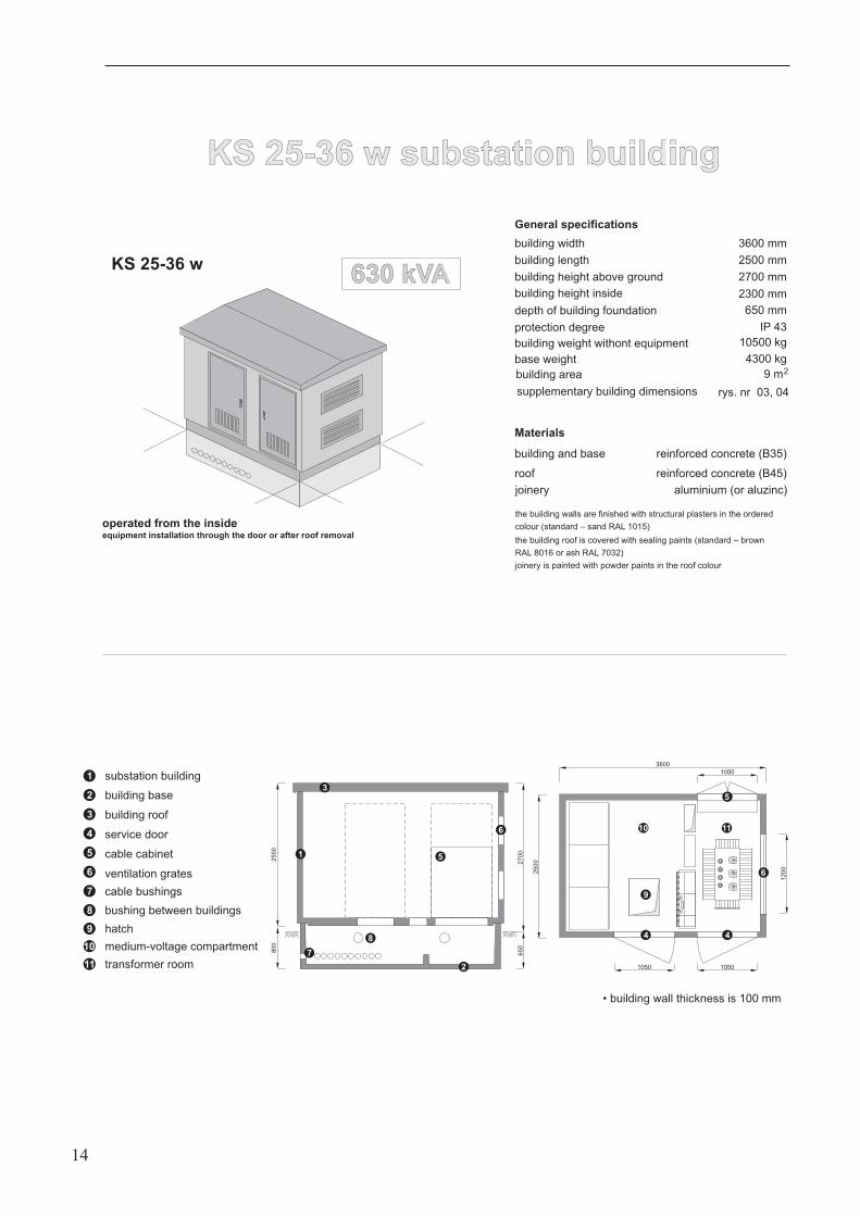
KS 22-30 w substation buildingKS 22-30 w substation building
equipment installation through the door or after roof removal
KS 22-30 w
operated from the inside
General specifications
building width
building length
building height above ground
depth of building foundation
protection degree
base weight
Materials
building and base
3000 mm
2200 mm
2700 mm
650 mm
IP 43
3600 kg
reinforced concrete (B35)
building height inside 2300 mm
building weight withont equipment 8000 kg
3000
1050
1050
1050
12
00
22
00
1
2
3
4
7
9
8
6
11
5
2700
650
2550
800
6
5
1
2
substation building
building base
3
4
building roof
service door
5
6
7
8
9
cable cabinet
ventilation grates
cable bushings
bushing between buildings
hatch
10 medium-voltage compartment
11 transformer room
10
4
• building wall thickness is 100 mm
630 kVA630 kVA
building area 6,6 m2
roof reinforced concrete (B45)
13
joinery
the building walls are finished with structural plasters in the ordered
colour (standard – sand RAL 1015)
the building roof is covered with sealing paints (standard – brown
RAL 8016 or ash RAL 7032)
joinery is painted with powder paints in the roof colour
aluminium (or aluzinc)
supplementary building dimensions fig.s 02 and 03
KS 25-36 w substation buildingKS 25-36 w substation building
KS 25-36 w
equipment installation through the door or after roof removal
operated from the inside
General specifications
building width
building length
building height above ground
depth of building foundation
protection degree
base weight
Materials
building and base
3600 mm
2500 mm
2700 mm
650 mm
IP 43
4300 kg
reinforced concrete (B35)
building height inside 2300 mm
building weight withont equipment 10500 kg
27
00
65
0
25
50
800
2
8
7
1
3
6
5
3600
10501050
1050
2500
12
00
4
9
11
5
6
4
10
1
2
substation building
building base
3
4
building roof
service door
5
6
7
8
9
cable cabinet
ventilation grates
cable bushings
bushing between buildings
hatch
10 medium-voltage compartment
11 transformer room
• building wall thickness is 100 mm
630 kVA630 kVA
building area 9 m2
roof reinforced concrete (B45)
14
joinery
the building walls are finished with structural plasters in the ordered
colour (standard – sand RAL 1015)
the building roof is covered with sealing paints (standard – brown
RAL 8016 or ash RAL 7032)
joinery is painted with powder paints in the roof colour
aluminium (or aluzinc)
supplementary building dimensions rys. nr 03, 04
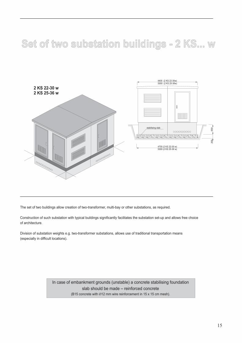
Set of two substation buildings - 2 KS... wSet of two substation buildings - 2 KS... w
The set of two buildings allow creation of two-transformer, multi-bay or other substations, as required.
Construction of such substation with typical buildings significantly facilitates the substation set-up and allows free choice
of architecture.
Division of substation weights e.g. two-transformer substations, allows use of traditional transportation means
(especially in difficult locations).
4400 (2 KS 22-30w)5000 (2 KS 25-36w)
65
03
00
2 KS 22-30 w2 KS 25-36 w
stabilising slab
4700 (2 KS 22-30 w)5300 (2 KS 25-36 w)
15
In case of embankment grounds (unstable) a concrete stabilising foundation
slab should be made – reinforced concrete
(B15 concrete with 12 mm wire reinforcement in 15 x 15 cm mesh).Ø
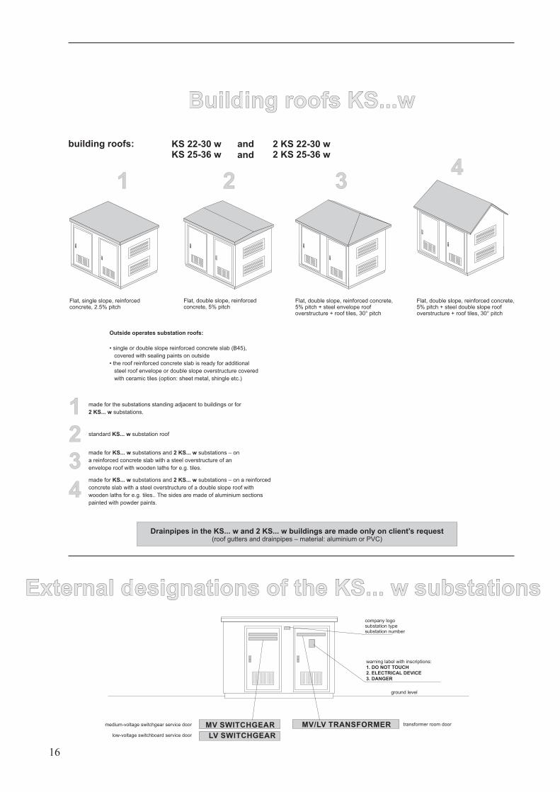
Flat, single slope, reinforcedconcrete, 2.5% pitch
Flat, double slope, reinforcedconcrete, 5% pitch
Flat, double slope, reinforced concrete,5% pitch + steel envelope roofoverstructure + roof tiles, 30° pitch
building roofs:
Flat, double slope, reinforced concrete,5% pitch + steel double slope roofoverstructure + roof tiles, 30° pitch
Outside operates substation roofs:
• single or double slope reinforced concrete slab (B45),
covered with sealing paints on outside
the roof reinforced concrete slab is ready for additional
steel roof envelope or double slope overstructure covered
with ceramic tiles (option: sheet metal, shingle etc.)
•
Building roofs KS...wBuilding roofs KS...w
1 2 34
made for the substations standing adjacent to buildings or for
substations.2 KS... w1
2 standard substation roofKS... w
3
4
made for substations and substations – on
a reinforced concrete slab with a steel overstructure of an
envelope roof with wooden laths for e.g. tiles.
KS... w 2 KS... w
made for substations and substations – on a reinforced
concrete slab with a steel overstructure of a double slope roof with
wooden laths for e.g. tiles.. The sides are made of aluminium sections
painted with powder paints.
KS... w 2 KS... w
Drainpipes in the KS... w and 2 KS... w buildings are made only on client’s request(roof gutters and drainpipes – material: aluminium or PVC)
KS 22-30 wKS 25-36 w
2 KS 22-30 w2 KS 25-36 w
ground level
MV SWITCHGEAR
LV SWITCHGEAR
medium-voltage switchgear service door
low-voltage switchboard service door
transformer room doorMV/LV TRANSFORMER
warning label with inscriptions:
1. DO NOT TOUCH
2. ELECTRICAL DEVICE
3. DANGER
company logosubstation typesubstation number
External designations of the KS... w substationsExternal designations of the KS... w substations
16
andand
17
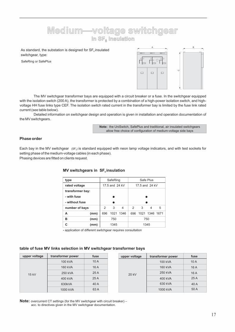
A B
C
type
rated voltage
transformer bay:
- with fuse
- without fuse
number of bays
A
B
C
2 3
696 1021 1346
4 2 3 4
696 1021 1346 1671
5
SafeRing
17.5 and 24 kV
750
1345
Safe Plus
17.5 and 24 kV
750
1345
(mm)
(mm)
(mm)
- application of different switchgear requires consultation
table of fuse MV links selection in MV switchgear transformer bays
Medium—voltage switchgearin SF insulation6
Medium—voltage switchgearin SF insulation6
SafeRing or SafePlus
The MV switchgear transformer bays are equipped with a circuit breaker or a fuse. In the switchgear equipped
with the isolation switch (200 A), the transformer is protected by a combination of a high-power isolation switch, and high-
voltage HH fuse links type CEF. The isolation switch rated current in the transformer bay is limited by the fuse link rated
current (see table below).
Detailed information on switchgear design and operation is given in installation and operation documentation of
the MV switchgears.
Note: overcurrent CT settings (for the MV switchgear with circuit breaker) –acc. to directives given in the MV switchgear documentation.
Phase order
Each bay in the MV switchgear is standard equipped with neon lamp voltage indicators, and with test sockets for
setting phase of the medium-voltage cables (in each phase).
Phasing devices are fitted on clients request.
(SF )6
MV switchgears in insulationSF6
As standard, the substation is designed for SF insulated
switchgear, type:
6
Note: the UniSwitch, SafePlus and traditional, air insulated switchgears
allow free choice of configuration of medium-voltage side bays
upper voltage transformer power fuse upper voltage transformer power fuse
15 kV 20 kV
100 kVA
160 kVA
250 kVA
400 kVA
630kVA
1000 kVA
10 A
16 A
25 A
25 A
40 A
63 A
100 kVA
160 kVA
250 kVA
400 kVA
630 kVA
1000 kVA
10 A
16 A
16 A
25 A
40 A
50 A
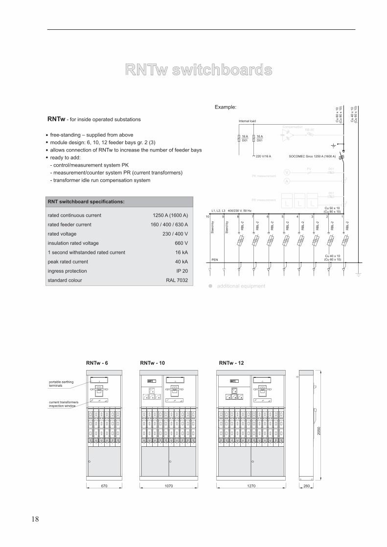
RNTw switchboardsRNTw switchboards
V
A A A
V
A A A
670
20
50
1070 1270 260
RNTw - 6 RNTw - 10 RNTw - 12
RNTw - for inside operated substations
free-standing – supplied from above
module design: 6, 10, 12 feeder bays gr. 2 (3)
allows connection of RNTw to increase the number of feeder bays
ready to add:
- control/measurement system PK
- measurement/counter system PR (current transformers)
- transformer idle run compensation system
rated continuous current
rated feeder current
rated voltage
insulation rated voltage
1 second withstanded rated current
peak rated current
ingress protection
standard colour
1250 A (1600 A)
160 / 400 / 630 A
230 / 400 V
660 V
16 kA
40 kA
IP 20
RAL 7032
RNT switchboard specifications:
current transformersinspection window
portable earthingterminals
18
SOCOMEC Sirco 1250 A (1600 A)220 V/16 A
RB
L-2
Sta
nd
-by
Sta
nd
-by
12345678910
PV
A
V
LLL 3
16 A
D01
16 A
D01
L1, L2, L3 400/230 V, 50 HzCu 50 x 10
(Cu 80 x 10)
Cu
60
x10
(Cu
80
x10)
Cu
40
x10
(Cu
60
x10)
3
D01
RB-00
D01
PENR
BL
-2
RB
L-2
RB
L-2
RB
L-2
RB
L-2
RB
L-2
RB
L-2
Internal load
Compensation
PK measurement
PR measurement
additional equipment
Cu 40 x 10(Cu 60 x 10)
Example:
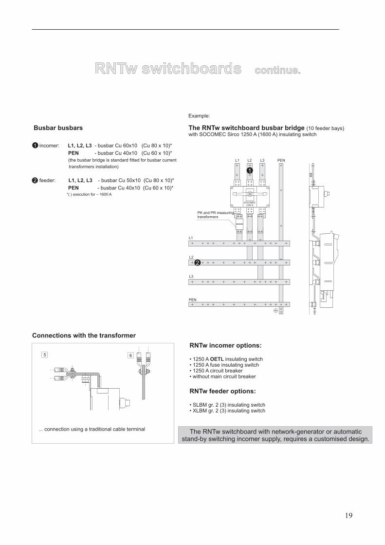
RNTw switchboards continue.RNTw switchboards continue.
19
incomer: - busbar Cu 60x10 (Cu 80 x 10)*
- busbar Cu 40x10 (Cu 60 x 10)*
feeder: - busbar Cu 50x10 (Cu 80 x 10)*
- busbar Cu 40x10 (Cu 60 x 10)*
Busbar busbars
L1, L2, L3
PEN
L1, L2, L3
PEN
(the busbar bridge is standard fitted for busbar current
transformers installation)
*( ) execution for – 1600 A
1
2
Connections with the transformer
SOCOMEC1250 A
... connection using a traditional cable terminal
5 6
L1 L2 L3 PEN
2
1
L1
L2
L3
PEN
PK and PR measuringtransformers
RNTw incomer options:
• 1250 A insulating switchOETL• 1250 A fuse insulating switch• 1250 A circuit breaker• without main circuit breaker
The RNTw switchboard busbar bridge (10 feeder bays)with SOCOMEC Sirco 1250 A (1600 A) insulating switch
Example:
The RNTw switchboard with network-generator or automaticstand-by switching incomer supply, requires a customised design.
RNTw feeder options:
• SLBM gr. 2 (3) insulating switch• XLBM gr. 2 (3) insulating switch
RNTw switchboards continue.RNTw switchboards continue.
20
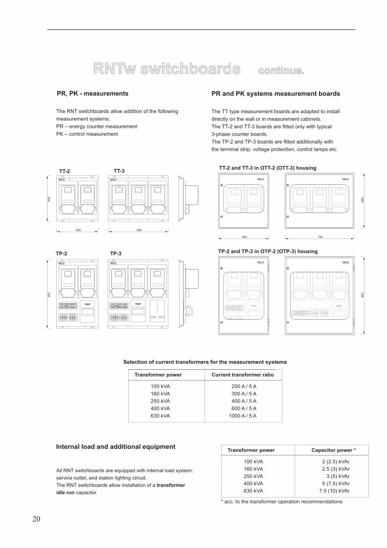
PR, PK - measurements
The RNT switchboards allow addition of the following
measurement systems:
PR – energy counter measurement
PK – control measurement
WILK
zegar
WILK
WILK WILK
TT-2 TT-3
TP-2 TP-3
zegarzegar
WILK
zegar
WILKWILK
WILKWILK
WILKWILK
TT-2 and TT-3 in OTT-2 (OTT-3) housing
TP-2 and TP-3 in OTP-2 (OTP-3) housing
PR and PK systems measurement boards
The TT type measurement boards are adapted to install
directly on the wall or in measurement cabinets.
The TT-2 and TT-3 boards are fitted only with typical
3-phase counter boards.
The TP-2 and TP-3 boards are fitted additionally with
the terminal strip, voltage protection, control lamps etc.
All RNT switchboards are equipped with internal load system:
service outlet, and station lighting circuit.
The RNT switchboards allow installation of a
capacitor.
transformer
idle run
Transformer power
100 kVA
160 kVA
250 kVA
400 kVA
630 kVA
Capacitor power *
2 (2.5) kVAr
2.5 (3) kVAr
3 (5) kVAr
5 (7.5) kVAr
7.5 (10) kVAr
Transformer power
100 kVA
160 kVA
250 kVA
400 kVA
630 kVA
Current transformer ratio
200 A / 5 A
300 A / 5 A
400 A / 5 A
600 A / 5 A
1000 A / 5 A
Selection of current transformers for the measurement systems
Internal load and additional equipment
650
850
750550
650450
500
700
* acc. to the transformer operation recommendations
21
A B
C
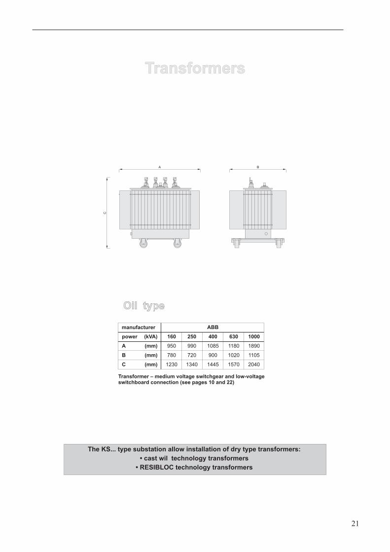
Transformers
The KS... type substation allow installation of dry type transformers:
• cast wil technology transformers
• RESIBLOC technology transformers
manufacturer
power
A
B
C
ABB
160
950
780
1230
(mm)
(mm)
(mm)
(kVA)
1340 1445 1570 2040
250
990
720
400
1085
900
630
1180
1020
1000
1890
1105
Transformer – medium voltage switchgear and low-voltageswitchboard connection (see pages 10 and 22)
Oil typeOil type
Medium-voltage and low-voltagecable connections
Medium-voltage and low-voltagecable connections
22
Transformer – medium-voltage switchgear connections
• single phase cables with 20 kV insulation:
up to 250 kVA 35 mm2
from 400 to 630 kVA 50 mm2
from 800 to 1250 kVA 70 mm2
The medium-voltage switchgears in SF6 insulation allow connection of dry or oil cables.
head manufacturer
SF6 insulated switchgears
line bays – incomer cables
transformer bay – cables to the transformer
F&G
ASTS 20/630; AWKS 20/630
EASW 20/250
EUROMOLD RAYCHEM
K400 TB; K400 LR
K 158 LR
RICS
RSES
Cable heads
head manufacturer
transformers
with traditional connectors (insulators)
with jack connectors
F&G
EASW 20/250; EASG 20/250
EUROMOLD RAYCHEM
K 158 LR RSES
EAVI 20; TI 24 ITK; OTK IXSU; OXSU
head manufacturer
air insulated switchgears
line bays – incomer cables
transformer bay – cables to the transformer
F&G EUROMOLD RAYCHEM
EAVI 20; TI 24
EAVI 20; TI 24
ITK; OTK
ITK; OTK
IXSU; OXSU
IXSU; OXSU
Transformer – low-voltage RNTz switchboard connections
• single phase cables with 1 kV insulation:
up to 250 kVA 1 x 240 mm2
from 400 to 630 kVA 2 x 240 mm2
from 800 to 1250 kVA 4x185 (240) mm2
KS 22-30 wKS 25-36 w
2 KS 22-30 w2 KS 25-36 w
Substation earthingSubstation earthing
Safety earthing:
• the substation equipment and structures and connected
to the earthing busbar with a green and yellow insulated
cable – 1 x 50 mm2.
• the earthing busbar is connected through a test
clamp 1 with external substation earthing
(flat section 200 mm2).
• the building reinforcement is used as additional, common
metallic connection for all substation structure components.
RNTw switchboard service earthing:
• the PEN terminal of the RNTw switchboard is connected
through the test clamp 3 with external substation earthing.
Transformer service earthing:
• the transformer neutral point is connected through the test
clamp 2 with external substation earthing.
• the connection of the test terminal with the transformer neutral
point is made with the 1 x 50 mm2 cable (1 x 120 mm2 or
25 x 4 mm2 tinned flat section – according to Electric Power
Distribution Company) – with blue insulation.
• to facilitate creation of substation earthing, flat-section FeZn
50 x 4 segments are included to connect the earthing points
number 1, 2, and 3 with the circumferential earthing.
FeZn 50x4 mm
Fe
Zn
50
x4m
m
PE
Earthing busbar
PE
N
LVsw
itchboard
RN
Tw
Fe
Zn
50
x4m
m
FeZn 50x4 mm
1
23
MV
switc
hgear
23
Substation installation and placementSubstation installation and placement
KS 22-30 w
KS 25-36 w
3000 2200
27
00
ground level
2500
3900
65
0
3300
4700
breakstone or reinforced concrete slab
15
0
Substation placement(with equipment)
19 T crane(25 T in case of difficulties)
traverse
12 T
3,6 T
3600 2500
27
00
2800
4200
65
0
3900
5300
15
0
ground level
Substation placement(with equipment)
19 T crane(25 T in case of difficulties)
traverse
breakstone or reinforced concrete slab
14,5 T
4,5 T
4400 (2 KS 22-30w)5000 (2 KS 25-36w)
65
03
00
common reinforced concrete slab
4700 (2 KS 22-30 w)5300 (2 KS 25-36 w)
3600
3900
5300
ground level
27
00
2 KS 22-30 w2 KS 25-36 w
24
• the installation traverse issupplied with the substation
• the lifting sling for roof removalis supplied with the substation
• the installation traverse issupplied with the substation
• the lifting sling for roof removalis supplied with the substation
In case of embankment grounds (unstable) a concrete stabilising foundation
slab should be made – reinforced concrete
(B15 concrete with 12 mm wire reinforcement in 15 x 15 cm mesh).Ø
KS 22-30 w
RNTw - 6, 10 bay
max. 630 kVA
1
2
3
4
5
6
7
8
9
10
11
concrete building
medium-voltage switchgear
MV/LV transformer
low-voltage switchboard
PR energy counter measurement
additional LV cable cabinet for installation of e.g.:
- individual LV switchboards
- board for street lighting
- PR energy counter measurement
service door 1050 x 2000 mm
transformer room door 1050 x 2000 mm
ventilation grates
MV cable duct
base hatch
Equipment placement
3000
10501050
12
00
22
00
1
2
3
4
7 8
9
11
3000
1050
1050
1050
12
00
22
00
1a
2
3
6
4
7 8
9
11
5
10
10
Transformer substation
KS 22-30 w
Substation equipment options - standard
substation building
LV switchboard
transformer
5
option with RNTw – 6
option with RNTw – 10and cable cabinet (6)
1a building with cable cabinet
MV switchgear: option: SF insulation – SafeRing or SafePlus
• up to 3 bays (24 kV))
6
option: air insulation – UniSwitch (compact)
• up to 3 bays (24 kV)
25
- capacitor set
fig. 8.1

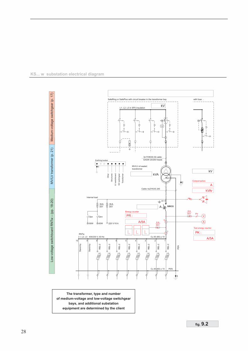
KS... w substation electrical diagram
Low
-voltage
sw
itchboard
RN
Tw
–(p
p.18-2
0)
MV
/LV
transfo
rmer
(p.21)
Mediu
m-v
oltage
sw
itchgear
(p.17)
Internal load
Test energy counter
Energy counter
Compensation
MV/LV oil sealed
transformer
4x2YKXS 240 cables
3x1YHKXS 50 cable
EASW 20/250 heads
SIRCO
Qsn
60W
Qnn
60W 220 V/16 A
RB
L-2
RB
L-2
RB
L-2
Sta
nd-b
y
Sta
nd-b
y
RB
L-2
RB
L-2
RB
L-2
RB
L-2
RB
L-2
12345678910
PV
A
V
LLL 3
3
kVAr
A
PK :
PR :
16 A
D01
6 A
D01
6 A
D01
16 A
D01
kV
A/5A
A/5A
L1, L2, L3 400/230 V, 50 Hz Cu 50 (80) x 10
Cu 40 (60) x 10
I>
L1, L2, L3 w in SF6 insulationkV
SafeRing or SafePlus with circuit breaker in the transformer bay with fuse ...
1
Earthing busbar
Oth
er
Str
uctu
res
LV
sw
itchboard
MV
sw
itchgear
Tra
nsfo
rme
r
2
PE
N
PEN
3
kVA
standard additional equipment
26
The transformer, type and number
of medium-voltage and low-voltage
switchgear bays, and additional substation
equipment are determined by the client
fig. 8.2
RNTw
KS 25-36 w (e.g. with cable cabinet)
RNTw - 6 (10) (12)
max. 630 kVA
Transformer substation
KS 25-36 w
Substation equipment options - standard
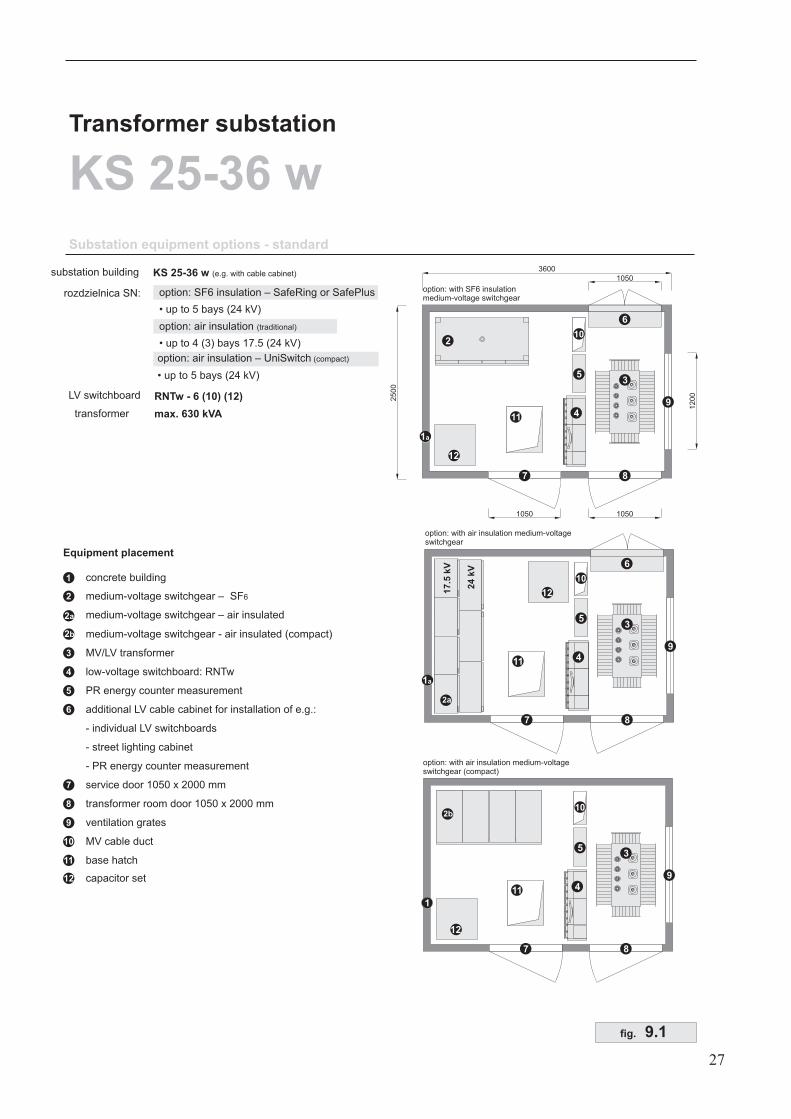
substation building
rozdzielnica SN:
LV switchboard
transformer
1
2
3
4
5
6
7
8
9
10
11
concrete building
medium-voltage switchgear – SF6
MV/LV transformer
low-voltage switchboard: RNTw
PR energy counter measurement
additional LV cable cabinet for installation of e.g.:
- individual LV switchboards
- street lighting cabinet
- PR energy counter measurement
service door 1050 x 2000 mm
transformer room door 1050 x 2000 mm
ventilation grates
MV cable duct
base hatch
Equipment placement
2a
2b
medium-voltage switchgear – air insulated
medium-voltage switchgear - air insulated (compact)
12 capacitor set
3
11 4
1
9
87
5
102b
12
3
11
9
87
6
10
17
.5k
V
2a
24
kV
4
5
option: with air insulation medium-voltageswitchgear
1a
12
3600
10501050
1050
25
00
12
00
3
11
2
9
87
6
10
4
5
option: with SF6 insulationmedium-voltage switchgear
1a
12
option: SF6 insulation – SafeRing or SafePlus
• up to 5 bays (24 kV)
option: air insulation
• up to 4 (3) bays 17.5 (24 kV)
(traditional)
option: air insulation – UniSwitch
• up to 5 bays (24 kV)
(compact)
27
option: with air insulation medium-voltageswitchgear (compact)
fig. 9.1
KS... w substation electrical diagram
Low
-voltage
sw
itchboard
RN
Tw
–(p
p.18-2
0)
MV
/LV
transfo
rmer
(p.21)
Mediu
m-v
oltage
sw
itchgear
(p.17)
Internal load
Test energy counter
Energy counter
Compensation
MV/LV oil sealed
transformer
4x2YKXS 240
3x1YHKXS 50 cable
Cable
EASW 20/250 heads
SIRCO
Qsn
60W
Qnn
60W 220 V/16 A
RB
L-2
RB
L-2
RB
L-2
Sta
nd-b
y
Sta
nd-b
y
RB
L-2
RB
L-2
RB
L-2
RB
L-2
RB
L-2
12345678910
PV
A
V
LLL 3
3
kVAr
A
PK :
PR :
16 A
D01
6 A
D01
6 A
D01
16 A
D01
kV
A/5A
A/5A
L1, L2, L3 400/230 V, 50 Hz Cu 50 (80) x 10
Cu 40 (60) x 10
I>
L1, L2, L3 in SF6 insulationkV
SafeRing or SafePlus with circuit breaker in the transformer bay with fuse ...
RNTw
1
Earthing busbar
Oth
er
Str
uctu
res
LV
sw
itchboard
MV
sw
itchgear
Tra
nsfo
rmer
2
PE
N
PEN
3
kVA
A
28
The transformer, type and number
of medium-voltage and low-voltage switchgear
bays, and additional substation
equipment are determined by the client
fig. 9.2
3600
10501050
1050
25
00
12
00
3
11 4
1
9
87
6
10
5
Transformer substation
KS 25-36 w
Substation equipment options: with medium-voltage side measurement
17
.5k
V
24
kV
RNTw - 6 (10) (12)
max. 630 kVA
LV switchboard
transformer
3
11 4
1
9
87
5
10
3
11
2
9
87
6
10
4
5
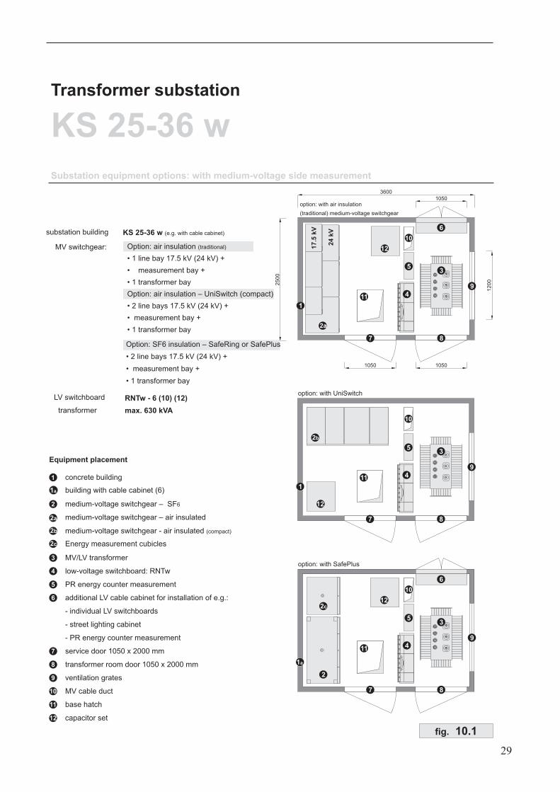
option: with UniSwitch
1a
2c
option: with air insulation
(traditional) medium-voltage switchgear
option: with SafePlus
1
2
3
4
5
6
7
8
9
10
11
concrete building
medium-voltage switchgear – SF6
MV/LV transformer
low-voltage switchboard: RNTw
PR energy counter measurement
additional LV cable cabinet for installation of e.g.:
- individual LV switchboards
- street lighting cabinet
- PR energy counter measurement
service door 1050 x 2000 mm
transformer room door 1050 x 2000 mm
ventilation grates
MV cable duct
base hatch
Equipment placement
1a building with cable cabinet (6)
2a
2b
medium-voltage switchgear – air insulated
medium-voltage switchgear - air insulated (compact)
2b
2c Energy measurement cubicles
12 capacitor set
12
12
12
KS 25-36 w (e.g. with cable cabinet)substation building
MV switchgear: Option: air insulation
• 1 line bay 17.5 kV (24 kV) +
• measurement bay +
• 1 transformer bay
(traditional)
Option: air insulation – UniSwitch (compact)
• 2 line bays 17.5 kV (24 kV) +
• measurement bay +
• 1 transformer bay
Option: SF6 insulation – SafeRing or SafePlus
• 2 line bays 17.5 kV (24 kV) +
• measurement bay +
• 1 transformer bay
29
2a
fig. 10.1
3x1YHKXS 50 cable
EASW 20/250 heads
EAVI 20 heads
Internal load
Test energy counter
Compensation
MV/LV oil sealed
transformer
4x2YKXS 240 cable
SIRCO
Qsn
60W
Qnn
60W 220 V/16 A
RB
L-2
RB
L-2
RB
L-2
Sta
nd-b
y
Sta
nd-b
y
RB
L-2
RB
L-2
RB
L-2
RB
L-2
RB
L-2
12345678910
PV
A
V
3
kVAr
PK :
16 A
D01
6 A
D01
16 A
D01
kV
A/5A
Cu 50 (80) x 10
Cu 40 (60) x 10
RNTw
RB-00
TP board
IMZ
UMZ
3
3L1, L2, L3 (SF6)
3xYHKXS 50 cable
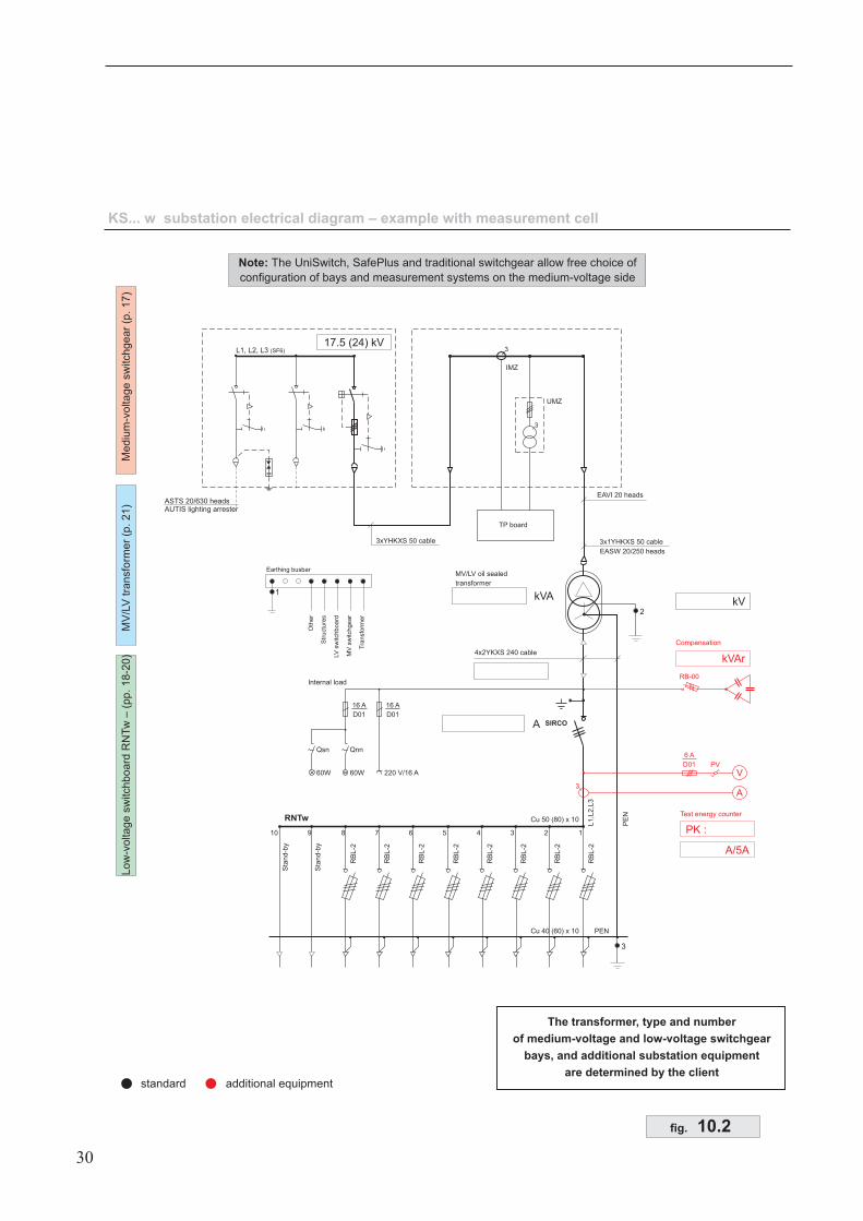
KS... w substation electrical diagram – example with measurement cell
standard additional equipment
Low
-voltage
sw
itchboard
RN
Tw
–(p
p.18-2
0)
MV
/LV
transfo
rmer
(p.21)
Mediu
m-v
oltage
sw
itchgear
(p.17)
17.5 (24) kV
1
Earthing busbar
Oth
er
Str
uctu
res
LV
sw
itchboard
MV
sw
itch
ge
ar
Tra
nsfo
rmer
2
L1,L
2,L
3
PE
N
PEN
3
ASTS 20/630 headsAUTIS lighting arrester
kVA
A
30
Note: The UniSwitch, SafePlus and traditional switchgear allow free choice of
configuration of bays and measurement systems on the medium-voltage side
The transformer, type and number
of medium-voltage and low-voltage switchgear
bays, and additional substation equipment
are determined by the client
fig. 10.2
Transformer substation
2KS 22-30 w
3
7
8
9
11
5 10
11
1
4
option: with UniSwitch
2b
3
7
8
9
11
5 10
11
1
4
option: with SafeRing or SafePlus
12
12
30
00
10
50
10
50
1200
4400
3
7
8
9
11
5 10
11
1
1050
4
17
.5k
V
24
kV
2
option: with air insulation (traditional) medium-voltage switchgear
2a12
1
2
3
4
5
6
7
8
9
10
11
concrete building
medium-voltage switchgear – SF6
MV/LV transformer
low-voltage switchboard: RNTw
PR energy counter measurement
additional LV cable cabinet for installation of e.g.:
- individual LV switchboards
- street lighting cabinet
- PR energy counter measurement
service door 1050 x 2000 mm
transformer room door 1050 x 2000 mm
ventilation grates
MV cable duct
base hatch
Equipment placement
2a
2b
medium-voltage switchgear – air insulated
medium-voltage switchgear - air insulated (compact)
12 capacitor set
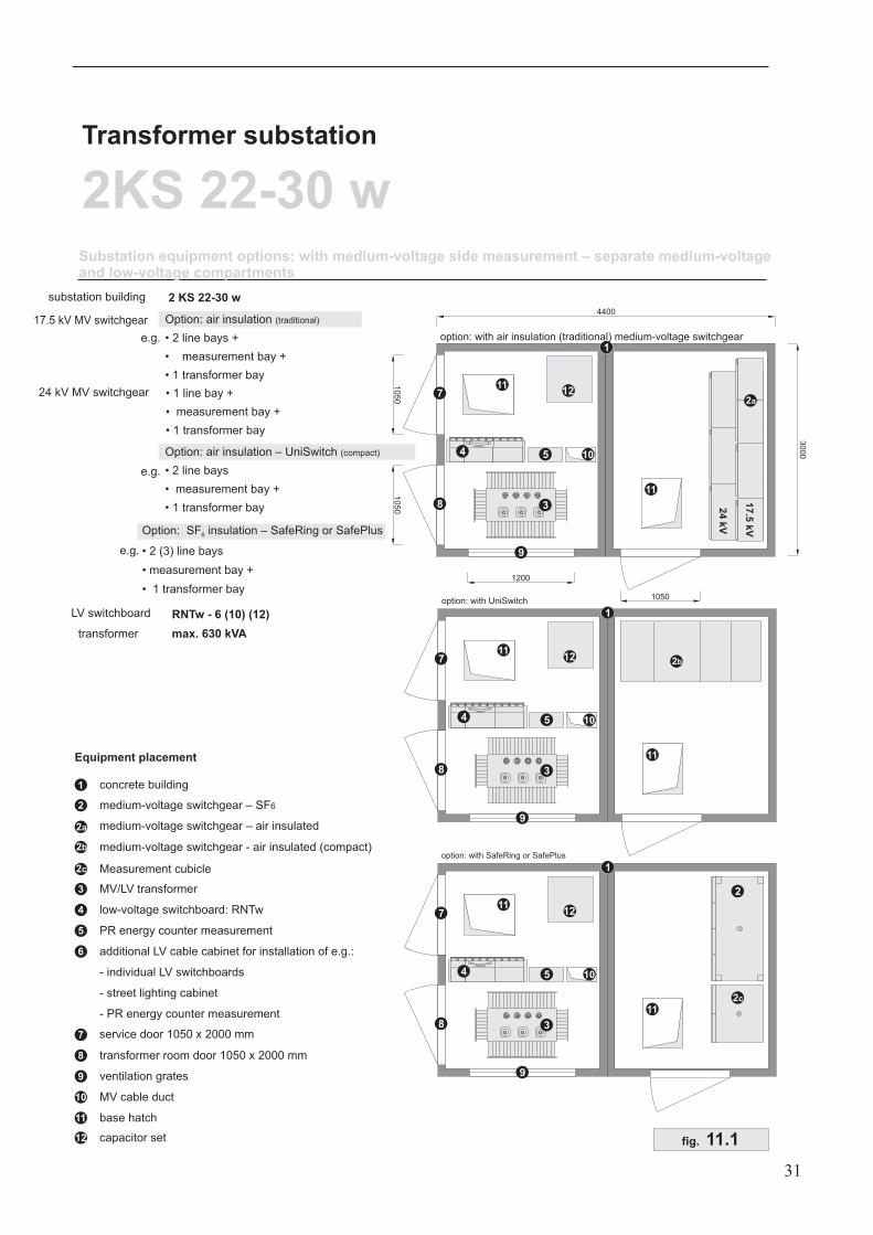
Substation equipment options: with medium-voltage side measurement – separate medium-voltageand low-voltage compartments
RNTw - 6 (10) (12)
max. 630 kVA
LV switchboard
transformer
2 KS 22-30 wsubstation building
17.5 kV MV switchgear Option: air insulation
• 2 line bays +
• measurement bay +
• 1 transformer bay
(traditional)
Option: air insulation – UniSwitch
• 2 line bays
• measurement bay +
• 1 transformer bay
(compact)
Option: SF insulation – SafeRing or SafePlus
• 2 (3) line bays
• measurement bay +
• 1 transformer bay
6
24 kV MV switchgear • 1 line bay +
• measurement bay +
• 1 transformer bay
e.g.
e.g.
e.g.
2
2c
2c Measurement cubicle
31
fig. 11.1
3x1YHKXS 50 cable
EASW 20/250 heads
L1, L2, L3
EAVI 20 heads
AHH
Tablica TP
IMZ
UMZ
3
3
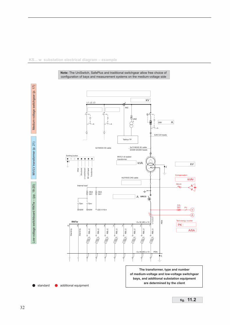
KS... w substation electrical diagram – example
standard additional equipment
Low
-voltage
sw
itchboard
RN
Tw
–(p
p.18-2
0)
MV
/LV
tra
nsfo
rme
r(p
.2
1)
Mediu
m-v
oltage
sw
itchgear
(p.17)
Internal load
Test energy counter
Compensation
MV/LV oil sealed
transformer
4x2YKXS 240 cable
SIRCO
Qsn
60W
Qnn
60W 220 V/16 A
RB
L-2
RB
L-2
RB
L-2
Sta
nd-b
y
Sta
nd-b
y
RB
L-2
RB
L-2
RB
L-2
RB
L-2
RB
L-2
12345678910
PV
A
V
3
kVAr
PK :
16 A
D01
6 A
D01
16 A
D01
kV
A/5A
Cu 50 (80) x 10
Cu 40 (60) x 10
RNTw
RB-00
3xYHKXS 50 cable
1
Earthing busbar
Oth
er
Str
uctu
res
LV
sw
itchboard
MV
sw
itchgear
Tra
nsfo
rmer
2
L1,L
2,L
3
PE
N
PEN
3
kVA
A
kV
32
The transformer, type and number
of medium-voltage and low-voltage switchgear
bays, and additional substation equipment
are determined by the client
fig. 11.2
Note: The UniSwitch, SafePlus and traditional switchgear allow free choice of
configuration of bays and measurement systems on the medium-voltage side
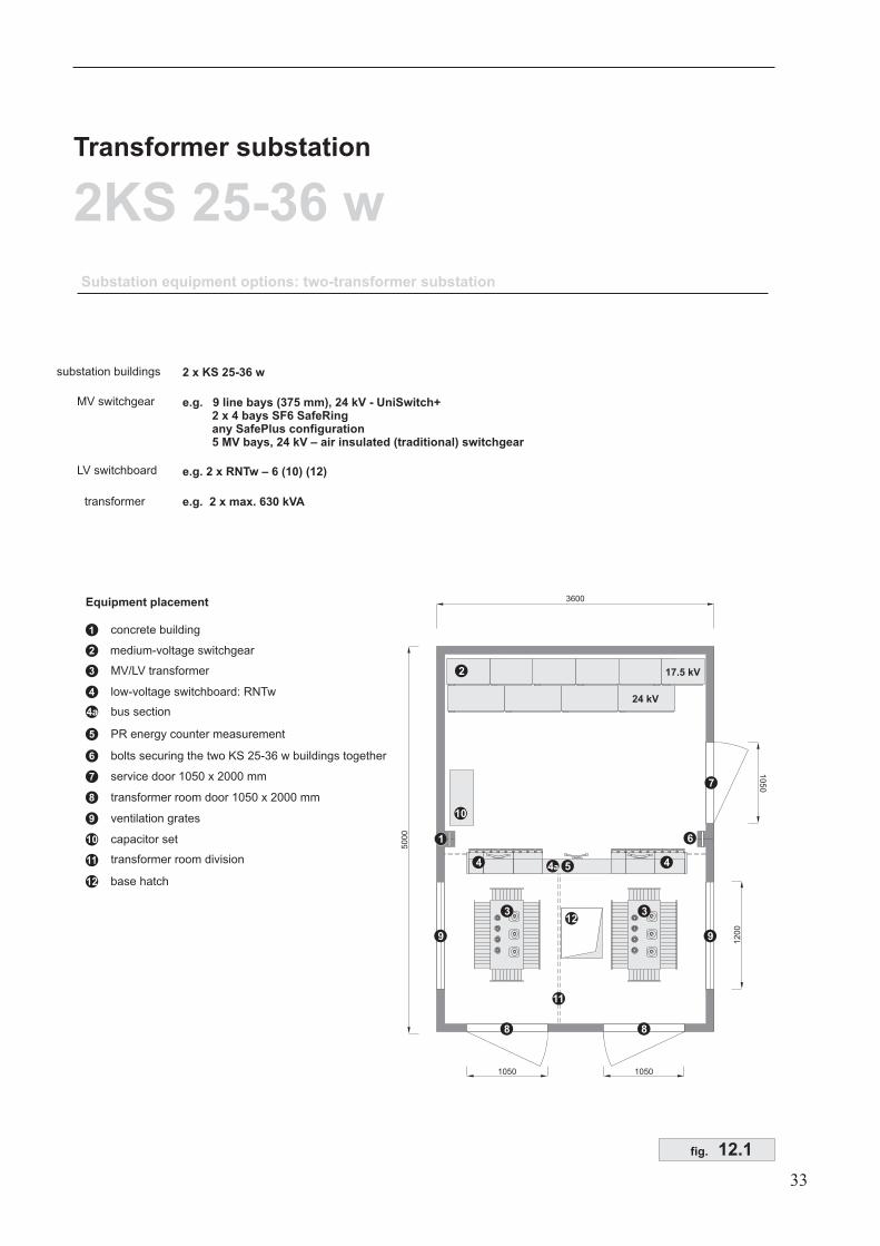
2 x KS 25-36 w
1
2
3
4
5
7
8
9
12
concrete building
medium-voltage switchgear
MV/LV transformer
low-voltage switchboard: RNTw
PR energy counter measurement
service door 1050 x 2000 mm
transformer room door 1050 x 2000 mm
ventilation grates
base hatch
Equipment placement 3600
10501050
50
00
12
00
9
8
1
3 3
9
8
e.g. 9 line bays (375 mm), 24 kV - UniSwitch+2 x 4 bays SF6 SafeRingany SafePlus configuration5 MV bays, 24 kV – air insulated (traditional) switchgear
e.g. 2 x max. 630 kVA
11
Transformer substation
2KS 25-36 w
e.g. 2 x RNTw – 6 (10) (12)
Substation equipment options: two-transformer substation
substation buildings
MV switchgear
LV switchboard
transformer
12
4
10
507
2
24 kV
17.5 kV
10
10 capacitor set
11 transformer room division4a4
4a bus section
6 bolts securing the two KS 25-36 w buildings together
5
6
33
fig. 12.1
EAVI 20 heads
AHH
EAVI 20 heads
AHH
L1, L2, L3
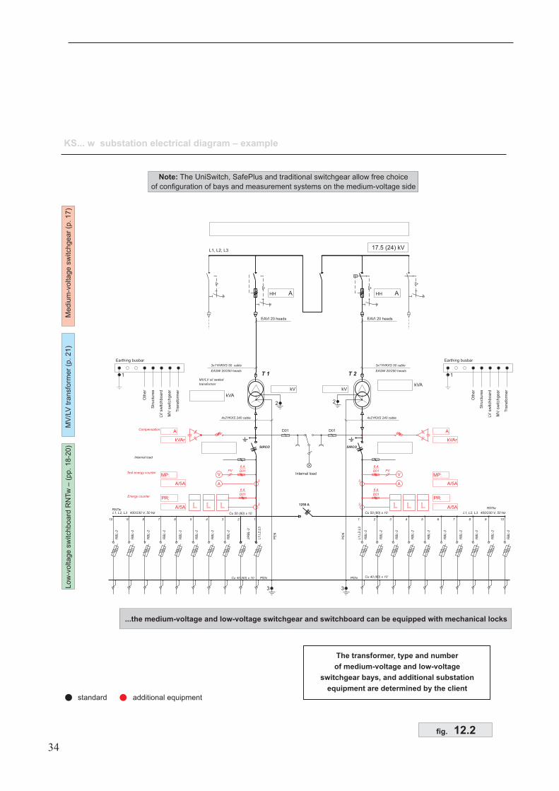
KS... w substation electrical diagram – example
17.5 (24) kV
standard additional equipment
Low
-voltage
sw
itchboard
RN
Tw
–(p
p.18-2
0)
MV
/LV
transfo
rmer
(p.21)
Mediu
m-v
oltage
sw
itchgear
(p.17)
PV
6 A
D01
6 A
D01
6 A
D01
6 A
D01
PV
AA
VV
33
MV/LV oil sealed
transformer
T 1 T 2
4x2YKXS 240 cable 4x2YKXS 240 cable
3x1YHKXS 50
EASW 20/250 heads
cable 3x1YHKXS 50 cable
EASW 20/250 heads
SIRCO
RB
L-2
RB
L-2
RB
L-2
RB
L-2
RB
L-2
RB
L-2
RB
L-2
RB
L-2
2R
BL
-2
RB
L-2
RB
L-2
RB
L-2
RB
L-2
RB
L-2
RB
L-2
RB
L-2
RB
L-2
11 22 33 44 55 66 77 88 99 1010
33
Compensation
Test energy counter
Internal load
Energy counter
RNTw RNTw
L1, L2, L3 400/230 V, 50 Hz L1, L2, L3 400/230 V, 50 HzCu 50 (80) x 10 Cu 50 (80) x 10
Cu 40 (60) x 10 Cu 40 (60) x 10
LL LL LL
kVArkVAr
AA
MP:MP:
PR:PR:
kV kV
A/5AA/5A
A/5AA/5A
1
Earthing busbar
Oth
er
Str
uctu
res
LV
sw
itchboard
MV
sw
itchgear
Tra
nsfo
rmer
kVA
kVA
SIRCO
2
3 3
2
PEN
L1
,L2
,L3
PE
N
L1
,L2
,L3
PE
N
PEN
1
Earthing busbar
Oth
er
Str
uctu
res
LV
sw
itchboard
MV
sw
itchgear
Tra
nsfo
rmer
RB
L-2
RB
L-2
1250 A
D01 D01
Internal load
34
fig. 12.2
Note: The UniSwitch, SafePlus and traditional switchgear allow free choice
of configuration of bays and measurement systems on the medium-voltage side
...the medium-voltage and low-voltage switchgear and switchboard can be equipped with mechanical locks
The transformer, type and number
of medium-voltage and low-voltage
switchgear bays, and additional substation
equipment are determined by the client
Substation equipment options: 1000 KVA transformer – separate medium-voltage and low-voltage(power distribution company and clients) compartments
substation buildings
3600
50
00
12
00
1
10
50
6
5
2
1
2
3
4
5
6
7
8
10
concrete building
medium-voltage switchgear
MV/LV transformer
low-voltage switchboard: RNTw – 1600 A
PR energy counter measurement
service door 1050 x 2100 mm
transformer room door 1200 x 2100 mm
ventilation grates
base hatch
Transformer substation
2KS 25-36 w
8
10
507
10
1000 kVA1000 kVA
1200
8
3
9
2 x KS 25-36 w
9 capacitor set
4
6
35
fig. 13
CustomerPower
Distribution
Company
e.g. 9 line bays (375 mm), 24 kV - UniSwitch+2 x 4 bays SF6 SafeRingany SafePlus configuration5 MV bays, 24 kV – air insulated (traditional) switchgear
1000 kVA
RNTw - 6 (10) (12)LV switchboard
transformer
MV switchgear
Equipment placement
01
fig.
KS
25-3
6w
su
bsta
tion
exte
rior
36
Exte
rior
2-3
Exte
rior
1-4
Exte
rior
1-2
Exte
rior
3-4
RO
OF
gre
yo
rb
row
nco
lou
r
RO
OF
gre
yo
rb
row
nco
lou
r
WA
LL
Ssa
nd
co
lou
r
ME
TA
LP
AR
TS
gre
yo
rb
row
nco
lou
r
TR
IMg
rey
or
bro
wn
co
lou
r
WA
LL
Ssa
nd
co
lou
r
TR
IMg
rey
or
bro
wn
co
lou
r
KS
22-3
0w
su
bsta
tion
eq
uip
men
tp
lacem
en
t
37
02
fig.
3-b
ay
Sa
feR
ing
me
diu
m-v
olta
ge
sw
itch
ge
arr
Ad
ditio
na
llo
w-v
olta
ge
eq
uip
me
nt
su
pp
ort
MV
/LV
tran
sfo
rme
r,m
ax
63
0kV
A,
dim
en
sio
ns
ma
x.
16
00
x1
03
0m
m
Tra
nsfo
rme
rm
ovin
gra
ils
Te
st
co
nn
ectio
n
Ca
ble
ba
se
ha
tch
Ea
rthin
gb
usb
ar
Te
st
co
nn
ectio
n
6-b
ay
low
-vo
ltag
esw
itch
bo
ard
WIL
KR
NTw
-6
03
fig.
KS
22-3
0w
su
bsta
tion
eq
uip
men
tp
lacem
en
t
38
Ca
ble
bu
sh
ing
s
Oil
pit

KS
25-3
6w
su
bsta
tion
eq
uip
men
tp
lacem
en
t
39
04
fig.
Ea
rthin
gb
usb
ar
5-b
ay
Sa
feP
lus
me
diu
m-v
olta
ge
sw
itch
ge
ar
10
-ba
ylo
w-v
olta
ge
sw
itch
bo
ard
WIL
KR
NT
w-1
0
Sa
fety
eq
uip
me
nt
ha
ng
er
Ca
ble
ba
se
ha
tch
Te
st
co
nn
ectio
n
Ad
ditio
na
llo
w-v
olta
ge
eq
uip
me
nt
su
pp
ort
MV
/LV
tran
sfo
rme
r,m
ax
63
0kV
A,
dim
en
sio
ns
ma
x.
16
00
x1
03
0m
m
Tra
nsfo
rme
rm
ovin
gra
ils
Te
st
co
nn
ectio
n
KS
25-3
6w
su
bsta
tion
eq
uip
men
tp
lacem
en
t
40
05
fig.
Ca
ble
bu
sh
ing
s
Oil
pit
Cab
leb
ush
ing
s
41
06
fig.
Ve
rsio
n1
Ve
rsio
n2
Ve
rsio
n3
P5
0ca
ble
bu
sh
ing
P7
0ca
ble
bu
sh
ing
HD
12
5(1
50
)ca
ble
bu
sh
ing
Th
erm
o-s
hrin
ktu
be
Th
erm
o-s
hrin
ktu
be
Th
erm
o-s
hrin
ktu
be
XP
LE
insu
late
do
rp
ap
er-o
ilin
su
late
dca
ble
XP
LE
insu
late
do
rp
ap
er-o
ilin
su
late
dca
ble
XP
LE
insu
late
dca
ble
KS
...wsu
bsta
tion
sjo
inery
fig. 0
7
42
The
KS
...wsubsta
tion
ventila
tion
gra
teK
S...
wsu
bsta
tion
se
rvic
ed
oo
r
Ca
se
me
nt-b
olt
lock
with
turn
/tilth
an
dle
Te
ch
nic
alsp
ecific
atio
ns:
1.M
ate
rial–
alu
min
ium
or
alu
zin
csh
ee
t2
.Fin
ish
co
atin
g–
po
lye
ste
rp
ow
de
rp
ain
t3
pro
tectio
n–
IP4
3G
rate
–o
nly
inth
etra
nsfo
rme
rro
om
do
or
Insect screen
Insect screen