ksb sicca® valves for the ansi world -...
TRANSCRIPT

®KSB SICCA Valves for the ANSI World
PDF processed with CutePDF evaluation edition www.CutePDF.com

Table of Contents
KSB Impetus
A catalyst for prosperity 1
KSB Milestones
Superlative success over the years 2
KSB Universe
Thriving through global proximity 3
KSB Focus
Valves on the fast track 4-5
KSB Competence
Potential extraordinary 6-7
Pressure Seal Valves®Pressure Seal Gate Valve - SICCA 900-2500 8-10®Pressure Seal Globe Valve - SICCA 900-2500 11-13®Pressure Seal Check Valve - SICCA 900-2500 14-16
Low Pressure Valves®Low Pressure Gate Valve - SICCA 150-600 17-19®Low Pressure Globe Valve - SICCA 150-600 20-22®Low Pressure Check Valve - SICCA 150-600 23-25
Forged Valve®Forged Gate Valve - SICCA 800-1500 26-27®Forged Globe Valve - SICCA 800-2500 28-30®Forged Check Valve - SICCA 800-2500 31-33
For all valves use operating instructions no. S500.80/01-18 G3

A catalyst for prosperity
Fluid, a force concealing an unrealised potential to animate or inanimate
the subordinate elements, is one of the most turbulent forces of nature.
Whenever there aries a need to harness this vibrant energy, KSB provides
the ultimate technology. Wherever the task, whatever the expectations,
KSB yields a free flow of solutions. Right from transportation and
distribution of water, waste water and industrial fluids, to thermal and
air conditioning problems... KSB regulates every element to perfection,
economically, efficiently and reliably. A technology leader offering total
fluid dynamics and handling solutions, KSB specialises in high-quality
customer care. Support that is extended through consultation, planning,
installation, maintenance and round the clock back-up. Committed to
technological progress, KSB works closely with academic and industrial
research partners located around the globe. An international
conglomerate today, KSB specialises in customising products, systems,
services and solutions to conquer the most dynamic, elemental force in
the world.
1
KSB Impetus

Superlative success over the years
In 1871, Johannes Klein received a Belgian patent for his boiler feed
apparatus; and the seeds of a revolution in pump and valve technology
were sown. Since its inception in Frankenthal, in 1871, KSB has been a
saga of success and glory.
1871 : Commencement of valveproduction in Germany.
1921 : The first patent of surfaceimprovement of mild steelthrough weld deposition ofStainless Steel
1922 : Development of acid resisting special alloy steel called Thermisilid together with Krupp for captive consumption by KSB. This became subsequently known in the industry under the nomendclature V2A and V4A.
1928 : The first patent on hard faced valve body seats. This paved the way for stelliting of valve seats to become a norm for all reputed valve manufacturers.
1929 : The patent for development of full flow 'Y' type Globe valve with very low flow resistance at 100 bar
0pressure and 500 C.
1937 : Development of the first BOA Globe Valve.
1940 : Development of Silicon valves for sulphuric acid.
1955 : Development of Ship-side'56 valves of sizes 16" & 32"
manufactured for the first time in nodular Cast Iron with approvals from Bureau Veritas, Det Norske Veritas and Lyold's Registrar.
1957 : Development of Bellow-seal valves for 160 bar pressure.
1963 : Radial Gate valve patented jointly with M/s Siemens with flow resistance of a gate valve and closing time of Globe valve.
1966 : Isolation valves of sizes 20" & 24" with spring loaded actuators, with a closing time of 3 to 5 seconds.
1968 : Bellow-seal valves with ceramic seat and disc for handling uranium suspension.
1973 : Development of the first Bellow-sea,l valve BOA - H for building services and steam applicationPN 16 - 40.
1974 : The first high temperature Gate and Globe valves for steam at 650 0C in ATS Steel (16 % Cr / 16% Ni).
1983 : 32" Globe valve medium controlled (stam) weighing 27.5 tons with an amazing closing time of 5 seconds for nuclear application, designed for 'g' value of 6 and the body machined out of a single piece forging weighing 100 tons.
1987 : Start of ANSI-valve production in Coimbatore (India).
1989 : Acquisition of AMRI Butterfly valves in La Roche Chalais (France), one of the leading Butterfly valve manufacturers in the world.The first valve in the world with oval seats - the BOA-Compact range.
1998 : BOA - Super Compact Globe Valve with end-to-end dimension equal to diameter, driven by the urge to serve the customer with the best in technology.
1999 : BOA Control IMS the first balancing valve with integrated sensor.
And the spirit of innovation lives on...
Frankenthal,1871 : Johannes Klein, Friedrich Schanzlin and August Becker set up a company called Klein, Schanzlin & Becker and KSB was born.
Some Milestones in Valve Technology
2
KSB Milestones
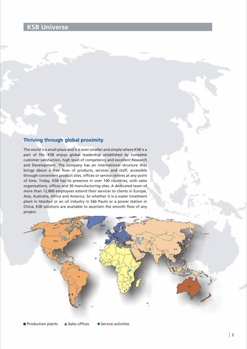
Thriving through global proximity
The world is a small place and it is even smaller and simple where KSB is a
part of life. KSB enjoys global leadership established by complete
customer satisfaction, high level of competency and excellent Research
and Development. The company has an international structure that
brings about a free flow of products, services and staff, accessible
through convenient product sites, offices or service centres at any point
of time. Today, KSB has its presence in over 100 countries, with sales
organisations, offices and 30 manufacturing sites. A dedicated team of
more than 12,800 employees extend their services to clients in Europe,
Asia, Australia, Africa and America. So whether it is a water treatment
plant in Istanbul or an oil industry in Sãb Paulo or a power station in
China, KSB solutions are available to ascertain the smooth flow of any
project.
2
3
4
13
12
5
6
2
3
Production plants Sales offices Service activities
3
KSB Universe

4
KSB Focus
Valves on the fast track
The valves programme got a shot in the arm on 1st January, 1997 with
the formation of a partially autonomous ‘‘Valves’’ unit. The valves unit
includes the German KSB Armaturen GmbH, founded at the start of the
year. It also covers the AMRI valves division of KSB S.A. in France and
SISTO Armaturen S.A. in Luxembourg.
A multinational team of design engineers from KSB Armaturen GmbH,
KSB Pumps Limited, India and MIL Controls Limited, KSB's control valve
manufacturer in India, have developed an extensive range of ANSI gate,
globe and check valves made of carbon steel conforming to ASTM valve
material standards. These global products are designed to cater to the
requirements of customers in industry, oil and gas, chemicals and power
engineering applications.
Today, KSB offers a full range of isolating, non-return and regulating
globe valves, butterfly valves, swing check valves, gate valves, diaphragm
valves, strainers, as well as actuated valves and control valves. Valves are
available in the nominal diameter spectrum from DN 8 to DN 3200 to
cover operating pressures of up to 600 bar and service temperatures 0 0from -200 C to 650 c.
Works at Pegnitz

5
KSB Focus
DN 300/250 PN 63Gate valve with pneumatic Actuator under testing
Painting of NORI 320 Globe valve

6
Potential extraordinaire
Coimbatore Valves Division
KSB Competence
Test RigHorizontal Machining Centre
7
KSB Competence
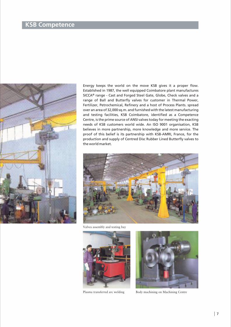
Energy keeps the world on the move KSB gives it a proper flow.
Established in 1987, the well equipped Coimbatore plant manufactures ®SICCA range - Cast and Forged Steel Gate, Globe, Check valves and a
range of Ball and Butterfly valves for customer in Thermal Power,
Fertilizer, Petrochemical, Refinery and a host of Process Plants. spread
over an area of 32,000 sq.m. and furnished with the latest manufacturing
and testing facilities, KSB Coimbatore, identified as a Competence
Centre, is the prime source of ANSI valves today for meeting the exacting
needs of KSB customers world wide. An ISO 9001 organisation, KSB
believes in more partnership, more knowledge and more service. The
proof of this belief is its partnership with KSB-AMRI, France, for the
production and supply of Centred Disc Rubber Lined Butterfly valves to
the world market.
Body machining on Machining Centre
Valves assembly and testing bay
Plasma transferred arc welding

8
Applications
l Power stations, general industry, process engineering
l For water, steam, gas, oil & other non-agressive media
l Further applications on request
Operating Data
l Pressure up to 439 bar( 6250 PSI )
l Temperature up to 0 0+593 C/1100 F
l Pressure-temperature ratings as per ASME B 16.34, Special class
Materials
ANSI Special class (as per ASME B 16.34)
l # 900/1500/2500 - A 216 WCB 0 0from 0 C to 425 C
l # 900/1500/2500 - A 217 0 0WC6/WC9 from 0 C to 593 C
l # Other materials on request
Design
l As per ASME B 16.34
l Pressure Seal Bonnet Design
l Stellite hard-faced Seats & Disc surface
l Graphite gaskets & packings with Braided wiping rings
l Direct retrofitting of Actuator
l Double disc wedge design
Variants on Request
l By-pass execution
l Actuator execution / Gear execution
l Bonnet pressure relief execution
l Position indicator
l Locking arrangement
l Other materials
l Other executions
Pressure Seal Gate Valve
®SICCA 900-2500
Type GTC
Pressure Seal Valves
Stem nut guided in bearingsl Ease of operationl Life time lubrication
Lock nut for stroke limitationl Prevents wedge from galling
Two piece gland arrangementl Self aligning bushl Even compression of packing ringsl No distortion on stem surface due
to improper assembly
Back seatl Additional stem seal for
emergency operationl Blow-out protection
Double disc wedge (split wedge) arrangementl Precise alignment to the body setsl Wedges are easy to replacel Tight at low differential pressurel No accelerated wear of sealing facesl Life extension due to provision of putting
shim between the spherical thrust rings
Yoke head equippedwith ISO-flange
l Retrofitting of actuator / gear box possible
Stem with burnished shankl Long gland life
Stellite hardfacing on ductile buffer layer
l Extended life time
Seal faces made of wear and corrosion-resistant materials
l High reliabilityl Long life

Flow Seal
l Fully stellited Body & Disc seats
l Seat rings - seal welded to body
l Lapped Seat & Disc faces for leak tightness
l Streamlined flow path ensures minimum pressure drop
Disc Design
l Self aligning double disc arrangement ensures perfect seating
l Wedging action ensures leak tightness
l Leak tightness at low & high differential pressure
l Extended wedge wear life by possibility of shim addition
Stem Wedge Connection
l Strong stem-disc joint capable of withstanding higher operating forces
Pressure Seal Bonnet
l Die moulded graphite gasket with reinforcement
l Segmental ring arrangement with knock out hole ensures easy disassembly
Gland Seal
l Die moulded graphite rings ensures effective sealing to atmosphere
l Top & bottom rings are braided graphite
l Braided rings offer smooth wiping action thereby arresting graphite depletion
l Smooth finished & polished stem and smooth stuffing box surfaces improve gland sealing life
l Two piece self aligning gland bolting arrangement
l Integral hard faced back seat for maximum service life
9
Stem with headfor the back seat,to relieve the stuffing box
Seat Stellite-6(HF)
Body
Seal welded seats
Self aligningdouble disc
Stellite 6(HF)
Pressure Seal Bonnetl Die moulded graphite
gasket reinforcedl Segmental ring arrangement
with knock out hole ensures easy disassembly
Bonnet
Graphite gasket
Spacer ring
Body
Knock-out hole
Thrust ring
Self aligning gland
Braided Graphite wipingrings at top & bottomDie moulded
Graphite rings
Integral Stellite-6 (HF)Backseat
Stem
Gland bush
Stem
Stem nut
Key
Retrofitting of Actuator
Mount Actuator with non-thrust base. Type `E’ or `B’ after removing handwheel.

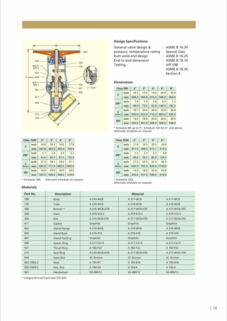
Design Specifications
General valve design & : ASME B 16.34
pressure, temperature rating Special class
Butt weld end design : ASME B 16.25
End to end dimension : ASME B 16.10
Testing : API 598
Dimensions
* Schedule 80 up to 3". Schedule 120 for 4" and above.Alternate schedule on request.
Inch
mm
Inch
mm
Inch
mm
Inch
mm
8.5
215.9
1.9
48.0
15.7
400.0
10.0
254.0
12.0
304.8
2.9
73.5
15.7
400.0
10.0
254.0
14.0
355.6
3.6
92.0
22.4
570.0
14.0
356.0
20.0
508.0
5.5
140.0
23.4
595.0
18.0
457.0
26.0
660.4
7.2
182.5
31.5
800.0
18.0
457.0
31.0
787.4
9.1
230.0
38.6
980.0
24.0
610.0
36.0
914.4
10.8
273.0
46.5
1180.0
24.0
610.0
E
ØB*
C
ØD
2" 3" 4" 6" 8" 10" 12"Class 900
(max.)
* Integral Bonnet back seat ST6 (HF)
Materials
Part No. Description Material
100
139
166
200
350
411
452
456
461
500
501
515
544
902.1/902.2
920.1/920.2
961
Body
Yoke
Bonnet *
Stem
Disc
Gasket
Gland Flange
Gland Bush
Gland Packing
Spacer Ring
Thrust Ring
Seat Ring
Stem Nut
Stud
Hex. Nut
Handwheel
A 216-WCB
A 216-WCB
A 216-WCB+ST6
A 479-410-2
A 216-WCB-ST6
Graphite
A 216-WCB
A 276-410
Graphite
A 217-CA15
A 182-F22
A 216-WCB+ST6
Al. Bronze
A 193-B7
A 194-2H
SG 400/12
A 217-WC9
A 216-WCB
A 217-WC9+ST6
A 479-410-2
A 217-WC9+ST6
Graphite
A 216-WCB
A 276-410
Graphite
A 217-CA15
A 182-F22
A 217-WC9+ST6
Al. Bronze
A 193-B16
A 194-4
SG 400/12
A 217-WC6
A 216-WCB
A 217-WC6+ST6
A 479-410-2
A 217-WC6+ST6
Graphite
A 216-WCB
A 276-410
Graphite
A 217-CA15
A 182-F22
A 217-WC6+ST6
Al. Bronze
A 193-B16
A 194-4
SG 400/12
* Schedule 160. Alternate schedule on request.
8.5
215.9
1.7
43.0
18.9
480.0
10.0
254.0
12.0
304.8
2.6
66.5
17.7
450.0
10.0
254.0
16.0
406.0
3.43
87.5
18.3
465.0
14.0
356.0
22.0
559.0
5.2
132.0
24.0
610.0
18.0
457.0
28.0
711.0
6.8
173.0
34.3
870.0
24.0
610.0
34.0
865.0
8.5
216.0
39.8
1011.0
24.0
610.0
39.0
991.0
10.1
257.0
46.9
1190.0
24.0
610.0
E
ØB*
C
ØD
Class 1500
Inch
mm
Inch
mm
Inch
mm
Inch
mm
2" 3" 4" 6" 8" 10" 12"
(max.)
10
fD
øB
C (max.)
139
920.2/902.2
452
501
411
166
350
920.1/902.1
SealWeld
E
100
515
500
461
456
200
544
961
* Schedule XXS up to 6". Schedule 160 for 8".Alternate schedule on request.$ Mandatory Gear Box
Class 2500 2"
E
ØB*
C
ØD
3" 4" 6" 8" 10" 12"
(max.)
11.0
279.0
1.5
38.0
19.1
485.0
14.0
356.0
14.5
368.0
2.3
58.5
17.3
440.0
18.0
457.0
18.0
459.0
3.2
80.0
22.2
565.0
20.0
508.0
24.0
610.0
4.9
124.5
27.4
695.0
20.0
508.0
30.0
762.0
6.8
173.0
34.4
875.0
24.0
610.0
36.0
914.4
8.5
216.0
61.0
1550.0
41.0
1041.4
10.1
257.0
61.0
1550.0
Inch
mm
Inch
mm
Inch
mm
Inch
mm$ $
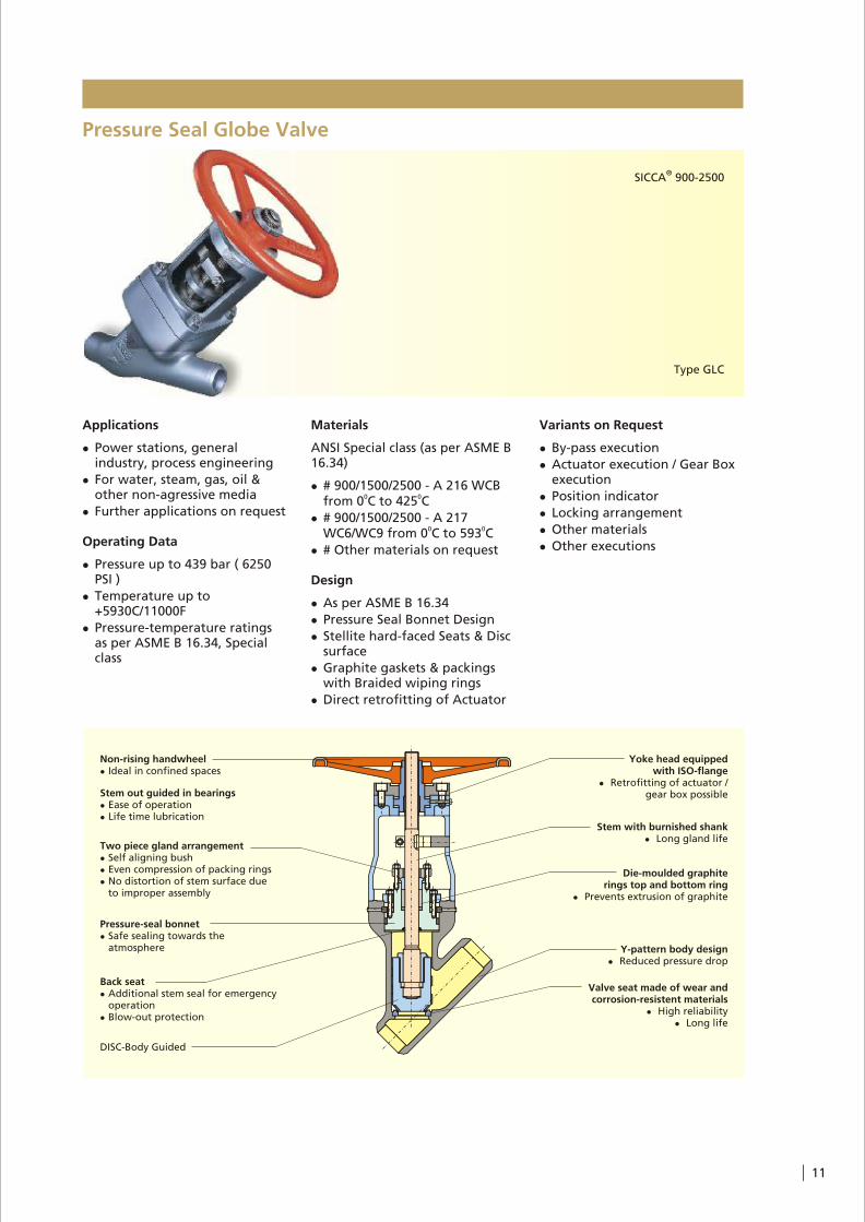
Applications
l Power stations, general industry, process engineering
l For water, steam, gas, oil & other non-agressive media
l Further applications on request
Operating Data
l Pressure up to 439 bar ( 6250 PSI )
l Temperature up to +5930C/11000F
l Pressure-temperature ratings as per ASME B 16.34, Special class
Materials
ANSI Special class (as per ASME B 16.34)
l # 900/1500/2500 - A 216 WCB 0 0from 0 C to 425 C
l # 900/1500/2500 - A 217 0 0WC6/WC9 from 0 C to 593 C
l # Other materials on request
Design
l As per ASME B 16.34
l Pressure Seal Bonnet Design
l Stellite hard-faced Seats & Disc surface
l Graphite gaskets & packings with Braided wiping rings
l Direct retrofitting of Actuator
Pressure Seal Globe Valve
Variants on Request
l By-pass execution
l Actuator execution / Gear Box execution
l Position indicator
l Locking arrangement
l Other materials
l Other executions
®SICCA 900-2500
Type GLC
11
Non-rising handwheell Ideal in confined spaces
Stem out guided in bearingsl Ease of operationl Life time lubrication
Two piece gland arrangementl Self aligning bushl Even compression of packing ringsl No distortion of stem surface due
to improper assembly
Back seatl Additional stem seal for emergency
operationl Blow-out protection
Yoke head equippedwith ISO-flange
l Retrofitting of actuator / gear box possible
Stem with burnished shankl Long gland life
Die-moulded graphite rings top and bottom ring
l Prevents extrusion of graphite
Y-pattern body designl Reduced pressure drop
Pressure-seal bonnetl Safe sealing towards the
atmosphere
Valve seat made of wear and corrosion-resistent materials
l High reliabilityl Long life
DISC-Body Guided
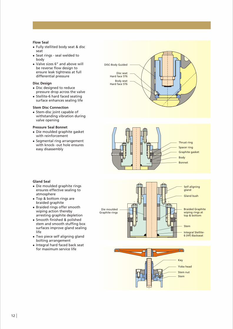
Flow Seal
l Fully stellited body seat & disc seat
l Seat rings - seal welded to body
l Valve sizes 6” and above will be reverse flow design to ensure leak tightness at full differential pressure
Disc Design
l Disc designed to reduce pressure drop across the valve
l Stellite-6 hard faced seating surface enhances sealing life
Stem Disc Connection
l Stem-disc joint capable of withstanding vibration during valve opening
Pressure Seal Bonnet
l Die moulded graphite gasket with reinforcement
l Segmental ring arrangement with knock- out hole ensures easy disassembly
Gland Seal
l Die moulded graphite rings ensures effective sealing to atmosphere
l Top & bottom rings are braided graphite
l Braided rings offer smooth wiping action thereby arresting graphite depletion
l Smooth finished & polished stem and smooth stuffing box surfaces improve gland sealing life
l Two piece self aligning gland bolting arrangement
l Integral hard faced back seat for maximum service life
12
DISC-Body Guided
Disc seatHard face ST6
Body seatHard face ST6
Thrust ring
Spacer ring
Graphite gasket
Body
Bonnet
Key
Yoke head
Stem nut
Stem
Self aligninggland
Braided Graphite wiping rings at top & bottom
Integral Stellite-6 (HF) Backseat
Stem
Gland bush
Die mouldedGraphite rings
Design Specifications
General valve design & : ASME B 16.34
pressure, temperature rating Special class
Butt weld end design : ASME B 16.25
End to end dimension : ASME B 16.10
Testing : API 598
ASME B 16.34
Section 8
Dimensions
* Schedule 80 up to 3". Schedule 120 for 4" and above.Alternate schedule on request.
(max.)
14.5
368.3
1.9
48.0
19.7
500.0
14.0
356.0
Inch
mm
Inch
mm
Inch
mm
Inch
mm
2"
E
ØB*
C
ØD
3" 4" 6" 8"Class 900
12.0
304.8
2.9
73.5
24.6
625.0
18.0
457.0
14.0
355.6
3.6
92.0
28.0
710.0
20.0
508.0
20.0
508.0
5.5
140.0
33.9
860.0
20.0
508.0
26.0
660.4
7.2
182.5
36.6
930.0
20.0
508.0
13
* Schedule 160. Alternate schedule on request.
E
ØB*
C
ØD
Class 1500
Inch
mm
Inch
mm
Inch
mm
Inch
mm
2" 3" 4" 6"
(max.)
14.6
369.8
1.7
43.0
27.2
690.0
14.0
356.0
18.5
469.9
2.6
66.5
28.1
715.0
20.0
508.0
16.0
406.4
3.4
87.5
34.6
880.0
20.0
508.0
27.8
706.4
5.2
132.0
41.1
1045.0
24.0
610.0
* Schedule XXS.Alternate schedule on request.
36.0
914.4
4.9
124.5
44.5
1130.0
24.0
610.0
26.5
673.1
3.2
80.0
32.3
820.0
20.0
508.0
14.5
368.3
2.3
58.5
29.5
750.0
18.0
457.0
17.8
451.0
1.5
38.0
27.2
690.0
14.0
356.0
Class 2500
Inch
mm
Inch
mm
Inch
mm
Inch
mm
2"
E
ØB*
C
ØD
3" 4" 6"
(max.)
* Integral Bonnet back seat ST6 (HF)
Materials
A 217-WC6
A 216-WCB
A 217-WC6+ST6
A 479-410-2
A 217-WC6+ST6
Graphite
A 216-WCB
A 276-410
Graphite
A 217-CA15
A 182-F22
A 217-WC6+ST6
Al. Bronze
A 193-B16
A 194-4
SG 400/12
A 217-WC9
A 216-WCB
A 217-WC9+ST6
A 479-410-2
A 217-WC9+ST6
Graphite
A 216-WCB
A 276-410
Graphite
A 217-CA15
A 182-F22
A 217-WC9+ST6
Al. Bronze
A 193-B16
A 194-4
SG 400/12
Part No. Description
100
139
166
200
350
411
452
456
461
500
501
515
544
902.1/902.2
920.1/920.2
961
Body
Yoke
Bonnet *
Stem
Disc
Gasket
Gland Flange
Gland Bush
Gland Packing
Spacer Ring
Thrust Ring
Seat Ring
Stem Nut
Stud
Hex. Nut
Handwheel
A 216-WCB
A 216-WCB
A 216-WCB+ST6
A 479-410-2
A 216-WCB-ST6
Graphite
A 216-WCB
A 276-410
Graphite
A 217-CA15
A 182-F22
A 216-WCB+ST6
Al. Bronze
A 193-B7
A 194-2H
SG 400/12
Material
C (max.)
E
ØB
544
902.2/920.2
452
456
920.1/902.1
461
411
350
515
100
200
961
139
166
501
500
2" TO 6"
14
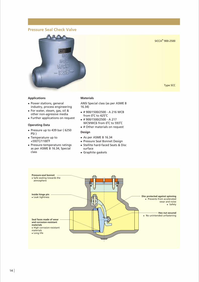
Pressure Seal Check Valve
Applications
l Power stations, general industry, process engineering
l For water, steam, gas, oil & other non-agressive media
l Further applications on request
Operating Data
l Pressure up to 439 bar ( 6250 PSI )
l Temperature up to 0 0+593 C/1100 F
l Pressure-temperature ratings as per ASME B 16.34, Special class
Materials
ANSI Special class (as per ASME B 16.34)
l # 900/1500/2500 - A 216 WCB 0 0from 0 C to 425 C
l # 900/1500/2500 - A 217 0 0WC9/WC6 from 0 C to 593 C
l # Other materials on request
Design
l As per ASME B 16.34
l Pressure Seal Bonnet Design
l Stellite hard-faced Seats & Disc surface
l Graphite gaskets
®SICCA 900-2500
Type SCC
Pressure-seal bonnetl Safe sealing towards the
atmosphere
Disc protected against spinningl Prevents from accelerated
wear and noisel Safety
Inside hinge pinl Leak tightness
Seal faces made of wearand corrosion-resistant materialsl High corrosion-resistantmaterialsl Long life
Hex nut securedl No unintended unfastening

Flow Seal
l Fully stellited, body & Disc seat
l Seat rings - seal welded to body
l Lapped Seat & Disc faces for leak tightness
l Streamlined flow path ensures minimum pressure drop
Disc Design
l Self aligning disc ensures perfect seating
l Designed to open at low differential pressure
Pressure seal
l Die-moulded graphite gasket with reinforcement
l Segmental ring arrangement with knock out holes provides for easy disassembly
15
Seat ringseal welded
Disc
Body
Graphitegasket
Spacer ring
Thrust ring
Bonnet
Hinge pin
Seat ring
Disc Carrier
Disc
Seal weld
Cotter pin

Design Specifications
General valve design & : ASME B 16.34
pressure, temperature rating Special class
Butt weld end design : ASME B 16.25
End to end dimension : ASME B 16.10
Testing : API 598
Materials
100
166
194
350
411
500
501
515
563
570
902
920
933
Body
Cover
Hinge Bracket
Disc
Gasket
Spacer Ring
Trust Ring
Seat Ring
Hinge Pin
Disc Carrier
Stud
Hex. Nut
Cotter Pin
A 216-WCB
A 216-WCB
A 216-WCB
A 216-WCB+ST6
Graphite
A 217-CA15
A 182-F22
A 216-WCB+ST6
A 479-410-1
A 216-WCB
A 193-B7
A 194-2H
A 276-304
A 217-WC9
A 217-WC9
A 217-WC9
A 217-WC9+ST6
Graphite
A 217-CA15
A 182-F22
A 217-WC9-ST6
A 479-410-1
A 217-WC9
A 193-B16
A 194-4
A 276-304
A 217-WC6
A 217-WC6
A 217-WC6
A 217-WC6+ST6
Graphite
A 217-CA15
A 182-F22
A 217-WC6+ST6
A 479-410-1
A 217-WC9
A 193-B16
A 194-4
A 276-304
Part No. Description Material
Dimensions
* Schedule 80 up to 3". Schedule 120 for 4" and above.Alternate schedule on request.
12"
14.5
215.9
1.9
48.0
6.5
165.0
Inch
mm
Inch
mm
Inch
mm
2"
E
ØB*
C
3" 4" 6" 8" 10"Class 900
12.0
304.8
2.9
73.5
8.5
215.0
14.0
355.6
3.6
92.0
11.0
280.0
20.0
508.0
5.5
150.0
12.2
310.0
26.0
660.4
7.2
182.5
14.0
356.0
31.0
787.4
9.0
230.0
17.0
431.0
36.0
914.4
10.8
273.0
20.1
511.0
* Schedule XXS up to 6". Schedule 160 for 8" and above.Alternate schedule on request.
Inch
mm
Inch
mm
Inch
mm
2"
E
ØB*
C
3" 4" 6" 8" 10" 12"
11.0
279.4
1.5
38.0
8.3
210.0
14.5
368.3
2.3
58.5
10.0
255.0
18.0
458.7
3.2
80.0
12.4
315.0
24.0
609.4
4.9
124.5
15.1
385.0
30.0
762.0
6.8
173.0
16.7
425.0
36.0
914.4
8.5
216.0
19.7
500.0
41.0
1041.4
10.1
257.0
24.8
630.0
Class 2500
* Schedule 160. Alternate schedule on request.
Inch
mm
Inch
mm
Inch
mm
2" 3" 4" 6" 8" 10" 12"
8.5
215.9
1.7
43.0
8.2
210.0
12.0
304.8
2.6
66.5
10.0
255.0
16.0
407.9
3.4
87.5
12.2
310.0
22.0
558.8
5.2
132.0
15.1
385.0
28.0
711.2
6.8
173.0
17.7
450.0
34.0
863.6
8.5
216.0
18.5
470.0
39.0
990.6
10.1
257.0
25.2
640.0
E
ØB*
C
Class 1500
16
C
E
ØB
SealWeld
350
515
563
411
920
902
501500
166194
570
933
100

Low Pressure Gate Valve
Applications
l Refineries, Power stations, Process & General Industry
l For water, steam, gas, oil and other non-agressive media
l Further applications on request
Operating data
l Pressure range up to 104 bar (1480 PSI)
l Temperature range up to 0 0+593 C/1100 F
0l Minimum temperature is 0 C
(less than 00C on request)
l Pressure-temperature ratings as per ASME B 16.34 Standard class
Materials
ANSI Standard Class (as per ASME B 16.34)
l #150/300/600 - A 216 WCB 0 0from 0 C to 425 C
0l #600 - A 217 WC6 from 0 C to
0593 C0
l #150/300 - A 351 CF8 from 0 C 0to 537 C
l ASME Special class on request.
Design
l As per API 600
l Pressure, Temperature rating as per ASME B 16.34
l Stellite hard-faced Seats
l Graphite gaskets and graphite packings with Braided wiping rings
Variants on Request
l Bypass execution
l Actuator execution
l Trim 8, Trim 5 for #150 / 300 valves
l Trim 5 for #600 WCB valves
l Trim 8 for #600 WC6 valves
l Other material of construction on request
l Position indicator
l Locking arrangement
®SICCA 150-600
Type GTC
17
Low Pressure Valves
Encapsulated spiral wound stainless steel gasket with graphite filling
l Secured sealing due to effective compression
Two piece gland arrangementl Self aligning bushl Even compression of packing ringsl No distortion on stem surface due
to improper assembly
Stem nut with Ni-steell Corrosion resistant in ammonia
atmosphere
Die-moulded graphite rings, top and bottom rings braided graphitel Prevents extrusion of graphite
High wear travel allowancel Extended maintenance-free
operating life time
Flexible wedge
Stem with burnished shankl Long gland life
Hardened stainless steel back seat bush
l Additional stem seal to guard emergency operation
l Blow - out protection
Seal faces made of wear and corrosion-resistant materials
l High reliabilityl Long life
Seal weld

Gland Seal
l Die moulded graphite rings ensures effective sealing to atmosphere
l Top & bottom rings are braided graphite offer smooth wiping action & prevents Graphite depletion
l Burnished stem and smooth stuffing box surfaces improve gland sealing life
l Two piece self aligning gland bolting arrangement
l Hardened [A276-410 (H)] back seat for maximum service life
Flow Seal
l Stellited body seats ( KSB recommends harder seats)
l Seat rings - seal welded to body
l Lapped seat and wedge faces for leak tightness
l Streamlined flow path hence no pressure drop
Wedge Design
l Flexible wedge ensures perfect seating
l Wedging action ensures leak tightness
l Leak tightness at low and high differential pressure
‘T’ head stem wedge connection
l Low centre stem to wedge contact reduces the operating torque
Bolted Bonnet
l Encapsulated Gasket ensures leak proof joint and prevents unwinding of SS strips
l #150 valve with oval/rectangular bonnet has flat gasket
18
GraphiteGasket
Burnisned stem
Self-aligninggland
Gland bush
Back seat bush
Die mouldedgraphite rings
Wedge
Seat
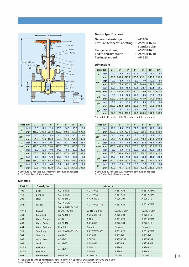
Design Specifications
General valve design : API 600
Pressure, temperature rating : ASME B 16.34
Standard class
Flanged end design : ASME B 16.5
End to end dimension : ASME B 16.10
Testing standard : API 598
Dimensions
* Schedule 40 for class 150. Alternate schedule on request.
E
ØB*
C
ØD
E**
ØF
(max.)
Inch
mm
Inch
mm
Inch
mm
Inch
mm
Inch
mm
Inch
mm
2" 3" 4" 6" 8" 10" 12"Class 150
7.0
178.0
2.0
51.0
12.2
310.0
8.0
203.0
8.5
216.0
2.0
52.5
8.0
203.0
3.0
76.0
14.2
360.0
10.0
254.0
11.1
282.0
3.1
78.0
9.0
229.0
4.0
102.0
16.5
420.0
10.0
254.0
12.0
305.0
4.0
102.0
10.5
266.7
6.0
152.0
22.1
560.0
14.0
356.0
15.9
403.0
6.1
154.0
11.5
292.1
8.0
203.0
28.7
730.0
18.0
457.0
16.5
419.0
8.0
203.0
13.0
330.0
10.0
254.0
35.4
900.0
18.0
457.0
18.0
457.0
10.0
254.0
14.0
356.0
12.0
305.0
42.5
1080.0
20.0
508.0
19.8
502.0
11.9
303.0
* Schedule 40 for class 300. Alternate schedule on request.E** - End to End of BW end valves.
19.8
502.0
12.0
305.0
43.7
1110.0
20.0
508.0
19.8
502.0
11.9
303.0
18.0
457.0
10.0
254.0
38.6
980.0
20.0
508.0
18.0
457.0
10.0
254.5
16.5
419.0
8.0
203.0
31.7
805.0
18.0
457.0
16.5
419.0
8.0
203.0
15.9
403.0
6.0
152.0
26.4
670.0
14.0
356.0
15.9
403.0
6.1
154.0
12.0
305.0
4.0
102.0
20.1
510.0
10.0
254.0
12.0
305.0
4.0
102.0
11.1
282.0
3.0
76.0
16.1
410.0
10.0
254.0
11.1
282.0
3.1
78.0
8.5
216.0
2.0
51.0
13.4
340.0
8.0
203.0
8.5
216.0
2.0
52.5
Class 300
Inch
mm
Inch
mm
Inch
mm
Inch
mm
Inch
mm
Inch
mm
2"
E
ØB*
C
ØD
E**
ØF
3" 4" 6" 8" 10" 12"
(max.)
* Schedule 80 for class 600. Alternate schedule on request.E** - End to End of BW end valves.
Inch
mm
Inch
mm
Inch
mm
Inch
mm
Inch
mm
Inch
mm
2"
E
ØB*
C
ØD
E**
ØF
3" 4" 6" 8" 10" 12"Class 600
(max.)
11.5
292.0
2.0
51.0
14.6
370.0
8.0
203.0
11.5
292.0
1.9
49.0
14.0
356.0
3.0
76.0
17.3
440.0
10.0
254.0
14.0
356.0
2.9
73.5
17.0
432.0
4.0
102.0
20.9
530.0
14.0
356.0
17.0
432.0
3.8
97.0
22.0
559.0
6.0
152.0
28.4
720.0
20.0
508.0
22.0
559.0
5.8
146.5
26.0
660.0
8.0
200.0
33.3
845.0
20.0
508.0
26.0
660.0
7.6
193.5
31.0
787.0
9.8
248.0
38.9
990.0
20.0
508.0
31.0
787.0
9.6
243.0
33.0
838.0
11.7
298.0
48.03
1220.0
24.0
610.0
33.0
838.0
11.4
289.0
* Flat graphite with SS reinforcement for # 150 only. Spiral wound gasket for # 300 and # 600.Note : Subject to change without notice on account of continuous improvement.
Materials
A 351-CF8M
A 351-CF8M
A 276-316
A 351-CF8M
SS 316 + GRPH
A 276-316
A 351-CF8M
A 276-316
Graphite
A 351-CF8M
A 439-D2
A 182-F304
A 193-B8M
A 194-8M
A 194-8M
SG 400/12
Body
Bonnet
Stem
Wedge
Gasket
Back Seat
Gland Flange
Gland Bush
Gland Packing
Seat Ring
Stem Nut
Gland Bolt
Stud
Hex. Nut
Hex. Nut
Handwheel
A 216-WCB
A 216-WCB
A 479-410-2
A 217-CA15
A 216-WCB+13%Cr
SS 316 + GRPH
A 276-410 (H)
A 105
A 276-410
Graphite
A 216-WCB+13%Cr
A 439-D2
A 307-B
A 193-B7
A 194-2H
SG 400/12
A 217-WC6
A 217-WC6
A 479-410-2
A 217-WC6+ST6
SS 316 + GRPH
A 276-410 (H)
A 105
A 276-410
Graphite
A 217-WC6+ST6
A 439-D2
A 307-B
A 193-B16
A 194-2H
A 194-4
SG 400/12
A 351-CF8
A 351-CF8
A 276-304
A 351-CF8
SS 316 + GRPH
A 276-304
A 351-CF8
A 276-304
Graphite
A 351-CF8
A 439-D2
A 182-F304
A 193-B8
A 194-8
A 194-8
SG 400/12
Description Material
100
166
200
361
* 411
450
452
456
461
515
544
900
902
920.1
920.2
961
Part No.
19
E**
ØF
515
100
361
200
411
450
461
456
452
920.2
900
544
961
166
920.1
902
ØD
C (max.)
ØB
E

Low Pressure Globe Valve
®SICCA 150-600
Type GLC
20
l ASME Special class on request.
Variants on Request
l Bypass execution
l Actuator execution
l Trim 8, Trim 5 for #150 / 300 valves
l Trim 5 for #600 WCB valves
l Trim 8 for #600 WC6 valves
l Other material of construction on request
l Position Indicator
l Locking arrangement
Design
l As per BS 1873
l Pressure, Temperature rating as per ASME B 16.34
l Stellite hard-faced Seat
l Graphite gaskets and graphite packings with Braided wiping rings
Materials
ANSI Standard Class (as per ASME B 16.34)
l #150/300/600 - A 216 WCB 0 0from 0 C to 425 C
0l #600 - A 217 WC6 from 0 C to
0593 C0
l #150/300 - A 351 CF8 from 0 C 0to 537 C
Applications
l Refineries, Power stations, Process & General Industry
l For water, steam, gas, oil and other non-agressive media
l Further applications on request
Operating data
l Pressure range up to 104 bar (1480 PSI)
l Temperature range up to 0 0+593 C/1100 F
0l Minimum temperature is 0 C
0(less than 0 C on request)
l Pressure-temperature ratings as per ASME B 16.34 Standard class
Two piece gland arrangementl Self aligning bushl Even compression of packing ringsl No distortion on stem surface due
to improper assembly
Stem nut with Ni-steell Corrosion resistant in ammonia
atmosphere
Die-moulded graphite rings, top and bottom ringsl Prevents extrusion of graphite
Hardened stainless steel back seat bushl Additional stem seal to guard
emergency operationl Blow-out protection
Stem with burnished shankl Long gland life
Encapsulated spiral wound stainless steel gasket with
graphite fillingl Secured sealing due to
effective compression
Valve seat made of wear and corrosion-resistant materialsl High reliabilityl Long life
Seal weld

Flow Seal
l Stellited body seat (KSB recommends harder seats)
l Seat rings seal welded to body
l Lapped seat and disc faces for leak tightness
Disc Design
l Rotating, self aligning disc
l Flat seating faces hence wide area of contact
Stem Disc Connection
l Stem-disc joint capable of withstanding vibration during valve opening
Gland Seal
l Die moulded graphite rings ensures effective sealing to atmosphere
l Top & bottom rings are braided graphite
l Braided rings offer smooth wipping action thereby arresting graphite depletion
l Burnished stem and smooth stuffing box surfaces improve gland sealing life
l Two piece self aligning gland bolting arrangement
l Hardened back seat for maximum service life
Bolted Bonnet
l Encapsulated Gasket ensures leak proof joint prevents unwinding of SS strip
21
Burnisned stem
Gland bush
Back seat bush
Die-mouldedgraphite rings
Flat Disc
Seat ringseal welded
Body
GraphiteGasket

Design Specifications
General valve design : BS 1873
Pressure, temperature rating : ASME B 16.34
Standard class
Flanged end design : ASME B 16.5
End to end dimension : ASME B 16.10
Testing standard : API 598
* Schedule 40 for class 150. Alternate schedule on request.E** - End to End of BW end valve.
Dimensions
2"
E
ØB*
C
ØD
E**
ØF
3" 4" 6" 8" 10"Class 150
(max.)
8.0
203.0
2.0
51.0
12.6
320.0
8.0
203.0
8.0
203.0
2.1
52.5
9.5
241.0
3.0
76.0
15.0
380.0
10.0
254.0
9.5
241.0
3.1
78.0
11.5
292.0
4.0
102.0
16.7
425.0
14.0
356.0
11.5
292.0
4.0
102.0
16.0
406.0
6.0
152.0
20.5
520.0
14.0
356.0
16.0
406.0
6.1
154.0
19.5
495.0
8.0
203.0
22.4
570.0
18.0
457.0
19.5
495.0
8.0
203.0
24.5
622.0
10.0
254.0
30.3
770.0
20.0
508.0
24.5
622.0
10.0
254.5
Inch
mm
Inch
mm
Inch
mm
Inch
mm
Inch
mm
Inch
mm
* Schedule 40 for class 300. Alternate schedule on request.E** - End to End of BW end valve.
10.5
267.0
2.0
51.0
13.4
340.0
8.0
203.0
10.5
267.0
2.0
52.5
12.5
318.0
3.0
76.0
15.8
400.0
10.0
254.0
12.5
318.0
3.1
78.0
14.0
356.0
4.0
102.0
17.9
456.0
14.0
356.0
14.0
356.0
4.0
102.0
17.5
445.0
6.0
152.0
21.5
545.0
18.0
457.0
17.5
445.0
6.1
154.0
22.0
559.0
8.0
203.0
28.5
725.0
20.0
508.0
22.0
559.0
8.0
203.0
24.5
622.0
10.0
254.0
32.7
830.0
20.0
508.0
24.5
622.0
10.0
254.5
Class 300
Inch
mm
Inch
mm
Inch
mm
Inch
mm
Inch
mm
Inch
mm
2"
E
ØB*
C
ØD
E**
ØF
3" 4" 6" 8" 10"
(max.)
* Schedule 80 for class 600. Alternate schedule on request.E** - End to End of BW end valve.
11.5
292.0
2.0
51.0
14.6
370.0
10.0
254.0
11.5
292.0
1.9
49.0
14.0
356.0
3.0
76.0
17.3
440.0
14.0
356.0
14.0
356.0
2.9
73.5
17.0
432.0
4.0
102.0
19.3
490.0
14.0
356.0
17.0
432.0
3.8
97.0
22.0
559.0
6.0
152.0
27.2
690.0
20.0
508.0
22.0
559.0
5.8
146.5
26.0
660.0
8.0
200.0
31.5
800.0
24.0
610.0
26.0
660.0
7.6
193.5
31.0
787.0
9.8
248.0
40.9
1040.0
24.0
610.0
31.0
787.0
9.6
243.0
Inch
mm
Inch
mm
Inch
mm
Inch
mm
Inch
mm
Inch
mm
E
ØB*
C
ØD
E**
ØF
(max.)
Class 600 2" 3" 4" 6" 8" 10"
Materials
Note : Subject to change without notice on account of continuous improvement.
Body
Bonnet
Stem
Disc
Gasket
Back Seat
Gland Flange
Gland Bush
Gland Packing
Seat Ring
Stem Nut
Gland Bolt
Stud
Hex. Nut
Hex. Nut
Handwheel
A 216-WCB
A 216-WCB
A 479-410-2
A 217-CA15
A 216-WCB+13%Cr
SS 316 + GRPH
A 276-410 (H)
A 105
A 276-410
Graphite
A 216-WCB+ST6
A 439-D2
A 307-B
A 193-B7
A 194-2H
SG 400/12
A 217-WC6
A 217-WC6
A 479-410-2
A 217-WC6+ST6
SS 316 + GRPH
A 276-410 (H)
A 105
A 276-410
Graphite
A 217-WC6+ST6
A 439-D2
A 307-B
A 193-B16
A 194-2H
A 194-4
SG 400/12
A 351-CF8
A 351-CF8
A 276-304
A 351-CF8
SS 316 + GRPH
A 276-304
A 351-CF8
A 276-304
Graphite
A 351-CF8
A 439-D2
A 182-F304
A 193-B8
A 194-8
A 194-8
SG 400/12
A 351-CF8M
A 351-CF8M
A 276-316
A 351-CF8M
SS 316 + GRPH
A 276-316
A 351-CF8M
A 276-316
Graphite
A 351-CF8M
A 439-D2
A 182-F304
A 193-B8M
A 194-8M
A 194-8M
SG 400/12
100
166
200
350
411
450
452
456
461
515
544
900
902
920.1
920.2
961
Part No. Description Material
22
515
100
350
411450
461
456
452
920.2
900200166544
961
920.1902
ØD
C (max.)
ØB
E
ØF
E**

Low Pressure Check Valve
Applications
l Refineries, Power stations, Process & General Industry
l For water, steam, gas, oil and other non-agressive media
l Further applications on request
Operating data
l Pressure range up to 104 bar (1480 PSI)
l Temperature range up to 0 0+593 C/1100 F
l Pressure-temperature ratings as per ASME B 16.34 Special class
Materials
ANSI Standard Class (as per ASME B 16.34)
l #150/300/600 - A 216 WCB 0 0from 0 C to 425 C
0l #600 - A 217 WC6 from 0 C to
0593 C0
l #150/300 - 351 CF8 from 0 C to 0537 C
l ASME Special class on request.
Design
l As per BS 1868
l Pressure, Temperature rating as per ASME B 16.34
l Stellite hard-faced Seats
Variants on Request
l Trim 8, Trim 5 for #150 / 300 valves
l Trim 5 for #600 WCB valves
l Trim 8 for #600 WC6 valves
l Other material of construction on request
l Drain Plug
®SICCA 150-600
Type SCC
23
Disc protected against spinningl Prevents from accelerated
wear and noisel Safety
Inside hinge pinl Leak tightness
Valve seat made of wear and corrosion-resistant materialsl High reliabilityl Long life
Hex nut securedl No unintended
unfastening
Encapsulated spiral wound stainless steel gasket with
graphite fillingl Secured sealing due to
effective compression

Disc Design
l Self aligning disc ensures perfect seating
l Designed to open at low differential pressure
Body Cover Joint
l Encapsulated Gasket ensures leak-proof and unwinding of SS spiral metal
Flow Seal
l Stellited seat
l Seat rings - seal welded to body
l Lapped Seat & Disc faces for leak tightness
l Streamlined flow path ensures minimum pressure drop
24
Hinge Pin
Disc Carrier
Disc
Cotter Pin
Seat Ring
Seat Weld
Disc
Seat seal welded
Body
EncapsulatedGasket
Body
Cover

Design Specifications
General valve design : BS 1868
Pressure, temperature rating : ASME B 16.34
Standard class
Flanged end design : ASME B 16.5
End to end dimension : ASME B 16.10
Testing standard : API 598
Dimensions
* Schedule 40 for class 150. Alternate schedule on request.E** - End to End of BW end valves.
8.0
203.0
2.0
51.0
6.3
160.0
8.0
203.0
2.1
53.0
9.5
241.0
3.0
76.0
7.5
190.0
9.5
241.0
3.1
78.0
11.5
292.0
4.0
102.0
9.1
230.0
11.5
292.0
4.0
102.0
14.0
356.0
6.0
152.0
10.2
260.0
14.0
356.0
6.1
154.0
19.5
495.0
8.0
203.0
12.0
305.0
19.5
495.0
8.0
203.0
24.5
622.0
10.0
254.0
15.0
380.0
24.5
622.0
10.0
255.0
27.5
699.0
12.0
305.0
16.1
410.0
27.5
699.0
11.9
303.0
Inch
mm
Inch
mm
Inch
mm
Inch
mm
Inch
mm
E
ØB
C
E**
ØF
2" 3" 4" 6" 8" 10" 12"Class 150
* Schedule 80 for class 600. Alternate schedule on request.E** - End to End of BW end valves.
33.0
838.0
11.7
298.0
21.3
540.0
33.0
838.0
11.4
289.0
31.0
787.0
9.8
248.0
18.1
460.0
31.0
787.0
9.6
243.0
26.0
660.0
8.0
200.0
15.7
400.0
26.0
660.0
7.6
194.0
22.0
559.0
6.0
152.0
12.2
310.0
22.0
559.0
5.8
146.5
17.0
432.0
4.0
102.0
10.2
260.0
17.0
432.0
3.8
97.0
14.0
356.0
3.0
76.0
9.4
240.0
14.0
356.0
2.9
74.0
11.5
292.0
2.0
51.0
7.5
190.0
11.5
292.0
1.9
49.0
Inch
mm
Inch
mm
Inch
mm
Inch
mm
Inch
mm
E
ØB
C
E**
ØF
Class 600 2" 3" 4" 6" 8" 10" 12"
10.5
267.0
2.0
51.0
5.9
150.0
10.5
267.0
2.1
53.0
12.5
318.0
3.0
76.0
8.7
220.0
12.5
318.0
3.1
78.0
14.0
356.0
4.0
102.0
9.4
240.0
14.0
356.0
4.0
102.0
17.5
445.0
6.0
152.0
11.4
290.0
17.5
445.0
6.1
154.0
21.0
533.0
8.0
203.0
13.4
340.0
21.0
533.0
8.0
203.0
24.5
622.0
10.0
254.0
15.4
390.0
24.5
622.0
10.0
255.0
28.0
711.0
12.0
305.0
17.3
440.0
28.0
711.0
11.9
303.0
Inch
mm
Inch
mm
Inch
mm
Inch
mm
Inch
mm
E
ØB
C
E**
ØF
2" 3" 4" 6" 8" 10" 12"Class 300
* Schedule 40 for class 300. Alternate schedule on request.
Materials
Note : Subject to change without notice on account of continuous improvement.
Part No. Description Material
100
160
194
350
411
515
563
570
902
920.1
Body
Cover
Hinge Bracket
Disc
SW Gasket
Seat Ring
Hinge Pin
Disc Carrier
Stud
Hex. Nut
A 216-WCB
A 216-WCB
A 216-WCB
A 217-CA15
A 216-WCB+13%Cr
SS 316 + GRPH
A 216-WCB + ST6
A 276-410 (H)
A 216-WCB
A 193-B7
A 194-2H
A 217-WC6
A 217-WC6
IS 2062
A 217-WC6 + ST6
SS 316 + GRPH
A 182-F11 + ST6
A 276-410 (H)
A 217 - WC6
A 193-B16
A 194-4
A 351-CF8
A 351-CF8
A 182-F304
A 351-CF8
SS 316 + GRPH
A 351-CF8
A 276-304
A 351-CF8
A 193-B8
A 193-B8
A 351-CF8M
A 351-CF8M
A 182-F304
A 351-CF8M
SS 316 + GRPH
A 351-CF8M
A 276-304
A 351 - CF8M
A 193 - B8M
A 194-8M
25
E**
ØF
C
ØB
E
920.1
902
160
411
194
563
570
350
515
100

Applications
l Power stations, general industry, process engineering
l For water, steam, gas, oil & other non-agressive media
l Further applications on request
Operating Data
l Pressure range up to 439 bar/( 6250 PSI )
l Temperature range up to 0 0+ 593 C / 1100 F
l Pressure-temperature ratings as per API 602 (# 800) and ASME B 16.34 (1500, 2500)
Materials
0 0l A 105 up to 425 C / 800 F
0 0l A 182-F22 up to 593 C / 1100 F
l # Other materials on request
Design
l API 602 (# 800 / 1500)
l Bolted bonnet for # 800
l Welded bonnet for # 1500 / 2500
l Socket weld for # 800-2500, socket thread NPT (F) for # 800
l Trim No. 8 (Stellite - 13% Cr) for # 800
Trim No. 8 (Stellite - 13% Cr) and No. 5 for # 1500
l Solid wedge
l Integral back seat
l Outside screw and yoke
l Non-rotating stem
Standard Variants
l Locking device
l Flanged ends to # 150 / 300 / 600 (welded on flanges)
l Actuator
l Other materials and Trim-Nos. on request
l Other variants on request
Forged Gate Valve
®SICCA 800-1500
Type GTF
26
Forged Valves
Two piece gland arrangementl Self aligning bushl Even compression of packing ringsl No distortion on stem surface due
to improper assembly Welded bonnet # 1500Bolted bonnet # 800 with
Encapsulated spiral wound stainless steel gasket with graphite filling
l Secured sealing due to effective compression
Burnished steml Long gland life
Die-moulded graphite rings, top and bottom rings braidedl Prevents extrusion of
graphite
Integral back seatl Additional stem seal to guard
emergency operationl Blow - out protection

Materials
Part No. Part Name Materials as per ASTM
100
166
200
360
411
452
456
461
515
544
901
902
920
961
Body
Bonnet
Stem
Wedge
Gasket
Gland flange
Gland bush
Gland packing
Seat ring
Stem nut
Hex bolt
Stud
Hex nut
Handwheel
A 105
A 105
A 479-410-2
A 217-CA15
SS+Graphite
A 105
A 276-410
Graphite
A 276-410+ST6
A 473-416
A 193-B7
A 193-B6
A 194-2H
IS 2108-A
Materials
Part No. Part Name Materials as per ASTM
100
166
200
360
452
456
461
515
544
902
920
961
Body
Bonnet
Stem
Wedge
Gland flange
Gland bush
Gland packing
Seat ring
Stem nut
Stud
Hex nut
Handwheel
A 105 A 182-F22
A 105 A 182-F22
A 479-410-2
A 217-CA15 Stellited
A 105
A 276-410
Graphite
A 276-410+ST6
A 473-416
A 193-B8M Cl.2
A 194-2H
IS 2108-A
# 1500 Gate Valve
Design Specifications
General valve design : API 602
Pressure-temp. ratings : ASME B 16.34
Socket weld end dimension : ASME B 16.11
End to end as per manufacturer's standard
# 800 Gate Valve
Design Specifications
General valve design : API 602
Pressure-temp. ratings : API 602
Socket weld end dimension : ASME B 16.11
End to end as per manufacturer's standard
27
Dimensions
Size B C DA E
inch
½
¾
1
1½
2
inch
0.9
1.1
1.3
1.9
2.4
inch
6.10
6.50
7.48
10.04
10.63
inch
3.74
3.74
5.00
5.79
5.79
mm
15
20
25
40
50
mm
21.8
27.1
33.8
48.7
61.1
mm
155
165
190
255
270
mm
95
95
127
147
147
inch
0.4
0.5
0.5
0.5
0.6
mm
9.5
13.0
13.0
13.0
16.0
inch
2.9
3.7
4.8
6.3
7.0
mm
73
94
122
160
178
Dimensions
inch
½
¾
1
1½
2
inch
0.9
1.1
1.3
1.9
2.4
inch
4.96
5.35
5.91
8.07
9.53
inch
3.74
3.74
4.06
5.00
5.79
mm
15
20
25
40
50
mm
21.8
27.1
33.8
48.7
61.1
mm
126
136
150
205
242
mm
95
95
103
127
147
inch
2.9
3.2
3.5
5.0
5.8
mm
73
82
90
127
148
Size B C D EA
inch
0.4
0.5
0.5
0.5
0.6
mm
9.5
13.0
13.0
13.0
16.0
øD
øB
E
A
C(max)Open
100
360
515
200
411
461
166
456
452
920/902
544
961
901
A
ØB
E
C(max)Open
ØD
Sealweld
456
515
100
360
200
166
461
902/920
452
544
961

Applications
l Power stations, general industry, process engineering
l For water, steam, gas, oil & other non-agressive media
l Further applications on request
Operating Data
l Pressure range up to 439 bar/( 6250 PSI )
l Temperature range up to 0 0+ 593 C / 1100 F
l Pressure-temperature ratings as per API 602 (# 800) and ASME B 16.34 (1500, 2500)
Forged Globe Valve
Materials
0 0l A 105 up to 425 C / 800 F
0 0l A 182-F22 up to 593 C / 1100 F
Design
l BS 5352 (# 800 / 1500)
l ASME B 16.34 (# 2500)
l Bolted bonnet for # 800
l Welded bonnet for # 1500/2500
l Socket weld for # 800-2500, socket thread NPT (F) for # 800
l Trim No. 8 (Stellite - 13% Cr) for # 800
Trim No. 8 (Stellite - 13% Cr) and
Trim No. 5 for # 1500
Trim No. 5 for # 2500
l Integral back seat
l Outside screw and yoke
l Rotating stem
Standard Variants
l Locking device
l Flanged ends to # 150 / 300 / 600
l Actuator
l Butt weld execution for # 800
l Other materials and Trim-Nos. on request
l Other variants on request
®SICCA 800-2500
Type GLF
28
Two piece gland arrangementl Self aligning bushl Even compression of packing ringsl No distortion on stem surface due
to improper assembly
Die-moulded graphite rings, top and bottom rings braided
l Prevents extrusion of graphite
Burnished steml Long gland life
Integral back seatl Additional stem seal to guard
emergency operationl Blow-out protection
Welded bonnet # 1500Bolted bonnet # 800 with
Encapsulated spiral wound stainless steel gasket with graphite filling
l Secured sealing due to effective compression

# 1500 Globe Valve
Design Specifications
General valve design : BS 5352
Pressure-temp. ratings : ASME B 16.34
Socket weld end dimension : ASME B 16.11
End to end as per manufacturer's standard
# 800 Globe Valve
Design Specifications
General valve design : BS 5352
Pressure-temp. ratings : ASME B 16.34
Socket weld end dimension : ASME B 16.11
End to end as per manufacturer's standard
Materials
Part No. Part Name Materials as per ASTM
100
166
200
350
411
452
456
461
515
544
901
902
920.1
920.2
961
Body
Bonnet
Stem
Disc
Gasket
Gland flange
Gland bush
Gland packing
Seat
Stem nut
Hex bolt
Stud
Hex nut
Handwheel
A 105
A 105
A 479-410-2
A 276-410 (H)
SS+Graphite
A 105
A 276-410
Graphite
ST6 (Integral)
A 582-416
A 193-B7
A 193-B6
A194-2H
IS 2108-A
Materials
Part No. Part Name Materials as per ASTM
100
166
200
350
452
456
461
515
544
902.1
920.1
920.2
961
Body
Bonnet
Stem
Disc
Gland flange
Gland bush
Gland packing
Seat
Stem nut
Stud
Hex nut
Handwheel
A 105 A 182-F22
A 105 A 182-F22
A 479-410-2
A 276-410 (H) SS 304+ST6
A 105
A 276-410
Graphite
ST6 (Integral)
A 582-416
A 193-B8M Cl.2
A 194-2H
IS 2108-A
29
Dimensions
Size B C DA E
inch
½
¾
1
1½
2
inch
0.9
1.1
1.3
1.9
2.4
inch
4.65
5.24
5.83
7.95
10.43
inch
2.95
2.95
4.72
5.67
5.67
mm
15
20
25
40
50
mm
21.8
27.1
33.8
48.7
61.1
mm
118
133
148
202
265
mm
75
75
120
144
144
inch
0.4
0.5
0.5
0.5
0.6
mm
9.5
13.0
13.0
13.0
16.0
inch
2.9
3.7
4.8
6.3
7.0
mm
73
82
90
127
148
Dimensions
inch
½
¾
1
1½
2
inch
0.9
1.1
1.3
1.9
2.4
inch
6.73
8.66
9.29
11.61
12.20
inch
5.00
7.28
7.28
7.99
7.99
mm
15
20
25
40
50
mm
21.8
27.1
33.8
48.7
61.1
mm
171
220
236
295
310
mm
127
185
185
203
203
inch
2.9
3.7
4.8
6.3
7.0
mm
73
94
122
160
178
Size B C D EA
inch
0.4
0.5
0.5
0.5
0.6
mm
9.5
13.0
13.0
13.0
16.0
Tackwelding
øD
A
øB
E
C(max)
Open
902/920.1
100
961
544
452
461
456920.2
200
166411
515
350
901
A
E
ØB
C(max)Open
ØD
515
100
350
456
461
166
452
200
Tack weld
544
961
Sealweld

# 2500 Globe Valve
Design Specifications
General valve design : ASME B 16.34
Pressure-temp. ratings : ASME B 16.34
Socket weld end dimension : ASME B 16.11
End to end as per manufacturer's standard
Materials
Part No. Part Name Materials as per ASTM
100
166
200
350
452
456
461
515
544
902
920
961
Body
Bonnet
Stem
Disc
Gland flange
Gland bush
Gland packing
Seat
Stem nut
Stud
Hex nut
Handwheel
A 105 A 182-F22
A 105 A 182-F22
A 479-410-2
SS 304+ST6
A 105
A 276-410
Graphite
ST6 (Integral)
A 582-416
A 193-B8M-Cl.2
A 194-2H
IS 2108-A
30
Dimensions
Size B C DA E
inch
0.4
0.5
0.5
0.5
0.6
mm
9.5
13.0
13.0
13.0
16.0
inch
½
¾
1
1½
2
inch
0.9
1.1
1.3
1.9
2.4
inch
7.32
8.66
9.45
11.81
14.96
inch
5.00
7.28
7.28
7.99
10.04
mm
15
20
25
40
50
mm
21.8
27.1
33.8
48.7
61.1
mm
186
220
240
300
380
mm
127
185
185
203
255
inch
3.3
3.9
4.1
5.7
5.7
mm
85
98
104
144
144
350
515
902/920
166
100
200
452
456
461
SealWeld
544
TACK WELD961
C(max)Open
E
A
B
D

Applications
l Power stations, general industry, process engineering
l For water, steam, gas, oil & other non-agressive media
l Further applications on request
Operating Data
l Pressure range up to 439 bar/( 6250 PSI )
l Temperature range up to 0 0+ 593 C / 1100 F
l Pressure-temperature ratings as per API 602 (# 800) and ASME B 16.34 (1500, 2500)
Forged Check Valve
l Spring loaded disc
Standard Variants
l Flanged ends to # 150 / 300 / 600
l Butt weld execution for # 800
l Other materials and Trim-Nos. on request
l Other variants on request
Materials
0 0l A 105 up to 425 C / 800 F
0 0l A 182-F22 up to 593 C / 1100 F
Design
l BS 5352 (# 800 / 1500)
l ASME B 16.34 (# 2500)
l Bolted cover for # 800
l Welded cover for # 1500 / 2500
l Socket weld for # 800-2500, socket thread NPT (F) for # 800
l Trim No. 8 (Stellite - 13% Cr) for # 800
Trim No. 8 (Stellite - 13% Cr) and No. 5 for # 1500
Trim No. 5 for # 2500
®SICCA 800-2500
Type PCF
31
Spring loaded discl Secured closing
operationindependent ofinstallationorientation

# 800 Check Valve
Design Specifications
General valve design : BS 5352
Pressure-temp. ratings : ASME B 16.34
Socket weld end dimension : ASME B 16.11
End to end as per manufacturer's standard
Materials
Part No. Part Name Materials as per ASTM
100
160
351
411
515
901
950
Body
Cover
Disc
Gasket
Seat
Hex bolt
Spring
A 105
A 105
A 279-410 (H)
SS+Graphite
ST6 (Integral)
A 193-B7
A 313-SS 302
# 1500 Check Valve
Design Specifications
General valve design : BS 5352
Pressure-temp. ratings : ASME B 16.34
Socket weld end dimension : ASME B 16.11
End to end as per manufacturer's standard
Materials
Part No. Part Name Materials as per ASTM
100
160
351
515
950
Body
Cover
Disc
Seat
Spring
A 105 A 182-F22
A 105 A 182-F22
A 279-410 (H) SS 304+ST6
ST6 (Integral) ST6 (Integral)
A 313-SS 302 A 313-SS 302
32
Dimensions
inch
½
¾
1
1½
2
inch
0.9
1.1
1.3
1.9
2.4
inch
1.97
2.36
2.56
3.54
4.92
mm
15
20
25
40
50
mm
21.8
27.1
33.8
48.7
61.1
mm
50
60
65
90
125
inch
2.9
3.2
3.5
5.0
5.8
mm
73
82
90
127
148
Size B C EA
inch
0.4
0.5
0.5
0.5
0.6
mm
9.5
13.0
13.0
13.0
16.0
Dimensions
Size B C EA
inch
½
¾
1
1½
2
inch
0.9
1.1
1.3
1.9
2.4
inch
2.56
3.15
3.74
4.72
5.51
mm
15
20
25
40
50
mm
21.8
27.1
33.8
48.7
61.1
mm
65
80
95
120
140
inch
2.9
3.2
3.5
5.0
5.8
mm
73
82
90
127
148
inch
0.4
0.5
0.5
0.5
0.6
mm
9.5
13.0
13.0
13.0
16.0
100
950
515
351
160
E
øB
C (max)
A
E
515
901
411
160
950
351
100
A
øB
C(max)

Materials
Part No. Part Name Materials as per ASTM
100
160
351
515
950
Body
Cover
Disc
Seat
Spring
A 105 A 182-F22
A 105 A 182-F22
SS 304+ST6 SS 304+ST6
ST6 (Integral) ST6 (Integral)
A 313-SS 302 A 313-SS 302
Dimensions
# 2500 Check Valve
Design Specifications
General valve design : ASME B 16.30
Pressure-temp. ratings : ASME B 16.34
Socket weld end dimension : ASME B 16.11
End to end as per manufacturer's standard
Dimensions
Size B CA E
inch
½
¾
1
1½
2
inch
0.9
1.1
1.3
1.9
2.4
inch
2.99
2.99
3.54
4.72
5.00
mm
15
20
25
40
50
mm
21.8
27.1
33.8
48.7
61.1
mm
76
76
90
120
127
inch
0.4
0.5
0.5
0.5
0.6
mm
9.5
13.0
13.0
13.0
16.0
inch
3.4
3.9
4.1
5.7
5.7
mm
85
98
104
144
144
Seal Weld160
950
351
515
100
ØB
C(max)
E
A

KSB Pumps LimitedH.O.: Mumbai-Pune Road, Pimpri, Pune 411 018. India.Tel.: +91 20 7472008, 7470990 Fax : +91 20 7476120Power Projects Division : D-II Block, MIDC, Pune 411 019.Tel.: +91 20 7473882, 7474213, 7474389 Fax : +91 20 7470890
edge/6'03/5000