kÜschall compact attract
TRANSCRIPT
Service Manual
KÜSCHALL COMPACT attract
DEALER: Keep this manual. The procedures in this manual MUST be performed by a qualified technician.

©2018 Invacare Corporation
All rights reserved. Republication, duplication or modification in whole or in part is prohibited without prior written permission from Invacare Corporation. Trademarks are identified by ™and ®. All trademarks are owned by or licensed to Invacare Corporation or its subsidiaries unless otherwise noted.
3
KÜSCHALL COMPACT attract
© Invacare Corporation | 2018-07
Service Manual
TABLE OF CONTENTS
GENERAL .......................................................................................................................5
Introduction 5Spare parts and adaptations 5Fastening with hexagon socket bolts 5Torque 6Checks 6Identifying and repairing faults 6
OVERVIEW ....................................................................................................................7
Components 7Dimensions 7
FRAME ....................................................................................................................... 8
Rear frame 9Front frame 9Retaining lever 9
SEAT ............................................................................................................................ 10
Seat height front (SHv) 10Seat height rear (SHh) 11Seat width (SB) 11Seat depth (ST) 11
BACKREST ...................................................................................................................13
Backrest height 13Angle-adjustable backrest 14Replacing push handles / push handles and backrest 16Replacing foldable push handles 18Stabilisation bar 18Backrest parts for adjustable backs with respect to backrest height 19
LEGRESTS ................................................................................................................... 23
Replacing legrest parts 23
FOOTRESTS ............................................................................................................... 24
Two-piece footrest 24Two-piece footrest, adjustable-angle 24
SIDEPARTS ................................................................................................................. 25
Clothes guard/mudguard 25Siderests 26
FRONT WHEELS ........................................................................................................ 30
Replacing a front wheel 30Front wheel fork 30Special housing guides 31
REAR WHEELS ........................................................................................................... 32
Adjusting the seat height rear 32Tipping stability 32Wheel camber 33Adjusting the removable axle 33Repairing or changing an inner tube 34Repairing or changing a solid tire 34
4
KÜSCHALL COMPACT attract
© Invacare Corporation | 2018-07
Service Manual
BRAKES ....................................................................................................................... 35
Parking brakes 35Drum brake 36
OPTIONS & ACCESSORIES .......................................................................................37
Antitipper 37Tipper aid/Cane holder 38Fitting the posture belt 39Attaching the snap hook symbols 39
5
KÜSCHALL COMPACT attract
© Invacare Corporation | 2018-07
Service Manual
GENERALIntroductionThis Service Manual contains all the technical information necessary for the inspection, configuration or repair of a küschall® wheelchair.
WARNING!Danger of accident and severe injuries.
If the wheelchair is improperly set it can cause accidents and severe injuries.
▸Changes to the wheelchair may only be carried out by the dealer.
To maintain the necessary levels of safety and reliability, every wheel-chair must be thoroughly examined once a year.
Some aspects of the assembly and configuration of the wheelchair require a high level of expertise. These assembly instructions there-fore break the various tasks down into three categories:
Requirement Symbol
Easy – technical understanding required ���
Medium – technical knowledge required ���
Difficult – technical knowledge and expertise in assembling wheelchairs required
���
The required tools and their sizes are listed before the instructions. The various torque values with which the nuts are to be tightened are also specified in the instructions. A torque spanner must be used, in order to comply with the specified torque values.
Tool Symbol
Allen key à 3, 4, 5
Torx wrench ß 8, 10, 20
Phillips head screwdriver Ò
Slot screwdriver
Open-end spanner 8, 9, 10, 18
Socket spanner/Box spanner 8, 10, 19, 22
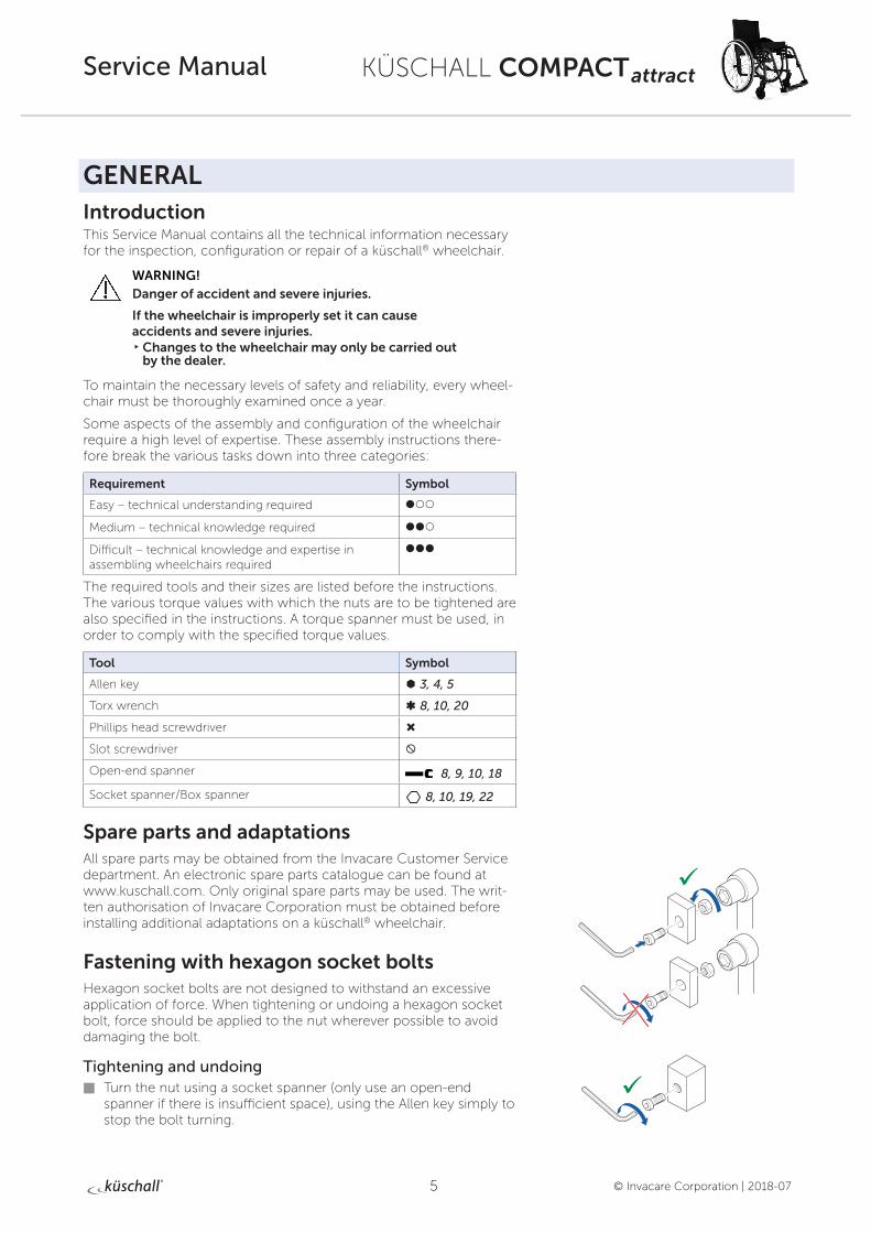
Spare parts and adaptationsAll spare parts may be obtained from the Invacare Customer Service department. An electronic spare parts catalogue can be found at www.kuschall.com. Only original spare parts may be used. The writ-ten authorisation of Invacare Corporation must be obtained before installing additional adaptations on a küschall® wheelchair.
Fastening with hexagon socket boltsHexagon socket bolts are not designed to withstand an excessive application of force. When tightening or undoing a hexagon socket bolt, force should be applied to the nut wherever possible to avoid damaging the bolt.
Tightening and undoing Turn the nut using a socket spanner (only use an open-end
spanner if there is insufficient space), using the Allen key simply to stop the bolt turning.
6
KÜSCHALL COMPACT attract
© Invacare Corporation | 2018-07
Service Manual
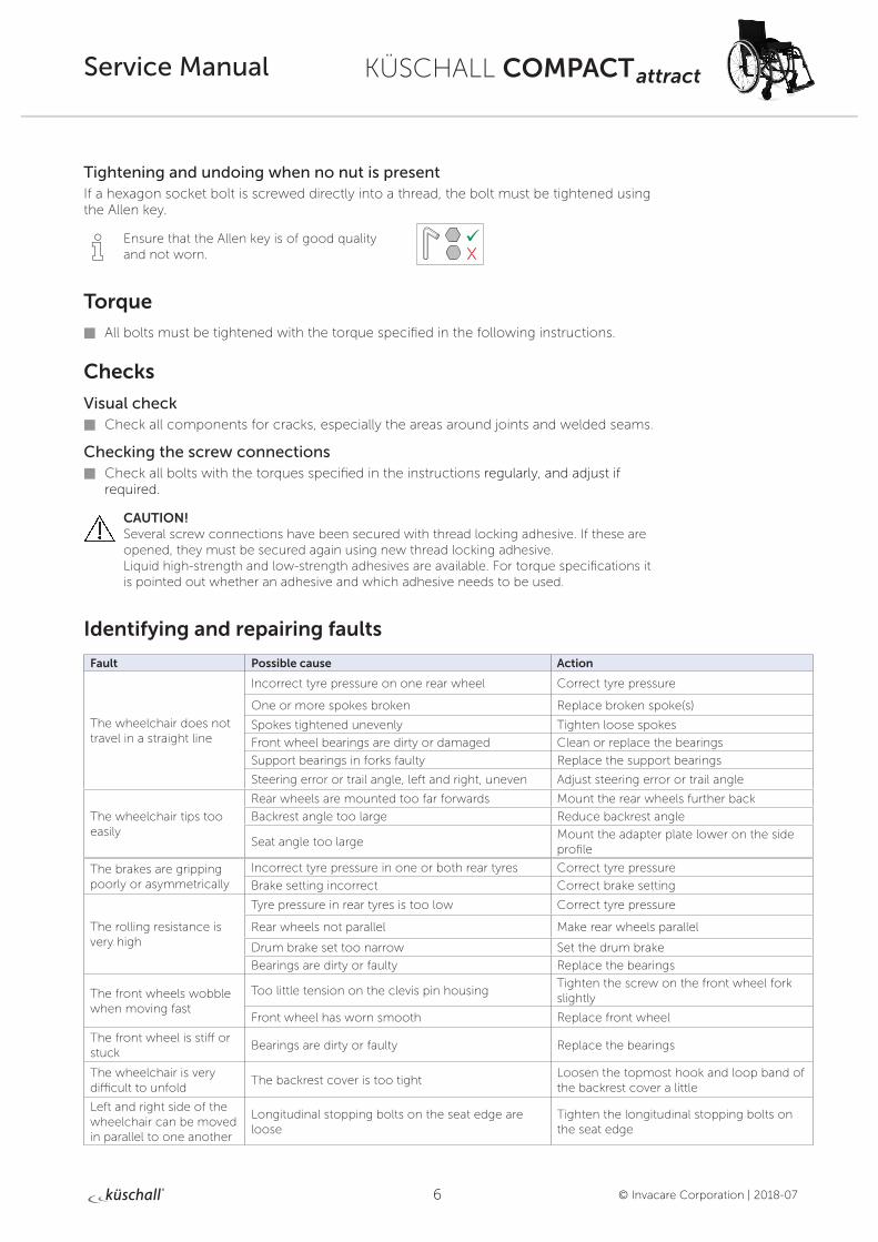
Tightening and undoing when no nut is presentIf a hexagon socket bolt is screwed directly into a thread, the bolt must be tightened using the Allen key.
i Ensure that the Allen key is of good quality and not worn.
Torque
All bolts must be tightened with the torque specified in the following instructions.
Checks
Visual check Check all components for cracks, especially the areas around joints and welded seams.
Checking the screw connections Check all bolts with the torques specified in the instructions regularly, and adjust if
required.
CAUTION! Several screw connections have been secured with thread locking adhesive. If these are opened, they must be secured again using new thread locking adhesive. Liquid high-strength and low-strength adhesives are available. For torque specifications it is pointed out whether an adhesive and which adhesive needs to be used.
Identifying and repairing faults
Fault Possible cause Action
The wheelchair does not travel in a straight line
Incorrect tyre pressure on one rear wheel Correct tyre pressure
One or more spokes broken Replace broken spoke(s)
Spokes tightened unevenly Tighten loose spokes
Front wheel bearings are dirty or damaged Clean or replace the bearings
Support bearings in forks faulty Replace the support bearings
Steering error or trail angle, left and right, uneven Adjust steering error or trail angle
The wheelchair tips too easily
Rear wheels are mounted too far forwards Mount the rear wheels further back
Backrest angle too large Reduce backrest angle
Seat angle too largeMount the adapter plate lower on the side profile
The brakes are gripping poorly or asymmetrically
Incorrect tyre pressure in one or both rear tyres Correct tyre pressure
Brake setting incorrect Correct brake setting
The rolling resistance is very high
Tyre pressure in rear tyres is too low Correct tyre pressure
Rear wheels not parallel Make rear wheels parallel
Drum brake set too narrow Set the drum brake
Bearings are dirty or faulty Replace the bearings
The front wheels wobble when moving fast
Too little tension on the clevis pin housingTighten the screw on the front wheel fork slightly
Front wheel has worn smooth Replace front wheel
The front wheel is stiff or stuck
Bearings are dirty or faulty Replace the bearings
The wheelchair is very difficult to unfold
The backrest cover is too tightLoosen the topmost hook and loop band of the backrest cover a little
Left and right side of the wheelchair can be moved in parallel to one another
Longitudinal stopping bolts on the seat edge are loose
Tighten the longitudinal stopping bolts on the seat edge
7
KÜSCHALL COMPACT attract
© Invacare Corporation | 2018-07
Service ManualOVERVIEW
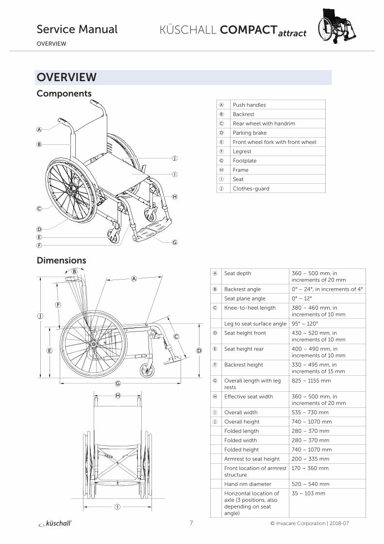
OVERVIEWComponents
Dimensions
A Push handles
B Backrest
C Rear wheel with handrim
D Parking brake
E Front wheel fork with front wheel
F Legrest
G Footplate
H Frame
I Seat
J Clothes-guard
A Seat depth 360 – 500 mm, in increments of 20 mm
B Backrest angle 0° – 24°, in increments of 4°
Seat plane angle 0° – 12°
C Knee-to-heel length 380 – 460 mm, in increments of 10 mm
Leg to seat surface angle 95° – 120°
D Seat height front 430 – 520 mm, in increments of 10 mm
E Seat height rear 400 – 490 mm, in increments of 10 mm
F Backrest height 330 – 495 mm, in increments of 15 mm
G Overall length with leg rests
825 – 1155 mm
H Effective seat width 360 – 500 mm, in increments of 20 mm
I Overall width 535 – 730 mm
J Overall height 740 – 1070 mm
Folded length 280 – 370 mm
Folded width 280 – 370 mm
Folded height 740 – 1070 mm
Armrest to seat height 200 – 335 mm
Front location of armrest structure
170 – 360 mm
Hand rim diameter 520 – 540 mm
Horizontal location of axle (3 positions, also depending on seat angle)
35 – 103 mm
8
KÜSCHALL COMPACT attract
© Invacare Corporation | 2018-07
Service ManualFRAME
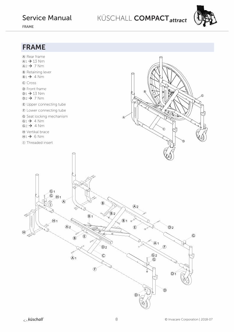
FRAME A Rear frame A1 à 13 Nm A2 à 7 Nm
B Retaining lever B1 à 4 Nm
C Cross
D Front frame D1 à 13 Nm D2 à 7 Nm
E Upper connecting tube
F Lower connecting tube
G Seat locking mechanism G1 à 4 Nm G2 à 4 Nm
H Vertikal brace H1 à 6 Nm
I Threaded insert
9
KÜSCHALL COMPACT attract
© Invacare Corporation | 2018-07
Service ManualFRAME
Rear frame
Replacing the rear frameDifficulty: ��� Tools: à 5 10
Remove backrest.
Loosen and remove bolts A1 and A2.
Pull out rear frame A to the back.
Remove seat locking mechanism G from old front frame and fit it on the new front frame, Chap. Seat; Turning the seat locking mechanism.
Push the rear frame onto the upper E and lower F connecting tubes.
Reinsert and tighten bolts A1 and A2.
Front frame
Replacing the front frameDifficulty: ��� Tools: à 3, 4, 5 10
Disassemble brakes.
Loosen and remove bolts D1 and D2 on both sides.
Pull out front frame D to the front.
Remove seat locking mechanism G from old front frame and fit it on the new front frame, Chap. Seat; Turning the seat locking mechanism.
Push the front frame onto the upper E and lower F connecting tube.
Reinsert and tighten bolts D1, D2 on both sides.
Set the front wheel fork angle, Chap. Front wheels; Setting the steering error angle.
Retaining lever
Replacing the retaining leverDifficulty: ��� Tools: à 4, 5 10
With mudguard or clothes guard, fixed: remove A1 and D2, with mudguard or side rest, insertable and siderest, foldable: remove A1 and A2.
Remove bolt B1.
Pull the retaining lever B from the upper connecting tube E.
Remove sleeve B2.
Push the new retaining lever over the upper connecting tube E.
Position sleeve B2 with wide edge in the aluminium tube.
Secure retaining lever with bolt B1.
With mudguard or clothes guard, fixed: reinsert and tighten bolts A1 and D2, with mudguard or side rest, insertable and side rest, flip to back: reinsert and tighten bolts A1 and A2.
10
KÜSCHALL COMPACT attract
© Invacare Corporation | 2018-07
Service ManualSEAT
SEAT
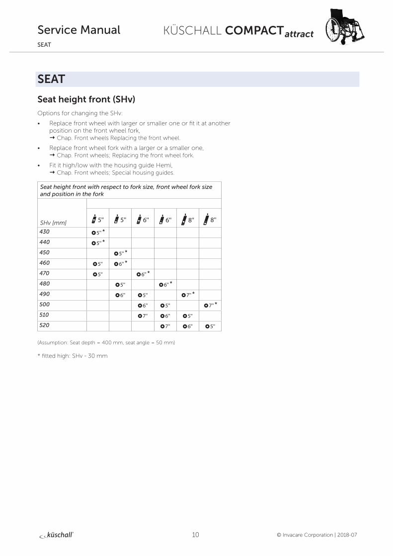
Seat height front (SHv)
Options for changing the SHv:
• Replace front wheel with larger or smaller one or fit it at another position on the front wheel fork, Chap. Front wheels Replacing the front wheel.
• Replace front wheel fork with a larger or a smaller one, Chap. Front wheels; Replacing the front wheel fork.
• Fit it high/low with the housing guide Hemi, Chap. Front wheels; Special housing guides.
Seat height front with respect to fork size, front wheel fork size and position in the fork
SHv [mm]
430 5'' *
440 5'' *
450 5'' *
460 5'' 6'' *
470 5'' 6'' *
480 5'' 6'' *
490 6'' 5'' 7'' *
500 6'' 5'' 7'' *
510 7'' 6'' 5''
520 7'' 6'' 5''
(Assumption: Seat depth = 400 mm, seat angle = 50 mm)
* fitted high: SHv - 30 mm
11
KÜSCHALL COMPACT attract
© Invacare Corporation | 2018-07
Service ManualSEAT
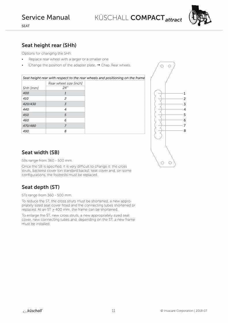
Seat height rear (SHh)
Options for changing the SHh:
• Replace rear wheel with a larger or a smaller one
• Change the position of the adapter plate, Chap. Rear wheels.
Seat height rear with respect to the rear wheels and positioning on the frame
SHh [mm]Rear wheel size [inch]
24’’
400 1
410 2
420/430 3
440 4
450 5
460 6
470/480 7
490 8
Seat width (SB)
SBs range from 360 - 500 mm.
Once the SB is specified, it is very difficult to change it: the cross struts, backrest cover (on standard backs), seat cover and, on some configurations, the footrests must be replaced.
Seat depth (ST)
STs range from 360 - 500 mm.
To reduce the ST, the cross struts must be shortened, a new appro-priately sized seat cover fitted and the connecting tubes shortened or replaced. At an ST ≥ 400 mm, the frame can be shortened.
To enlarge the ST, new cross struts, a new appropriately sized seat cover, new connecting tubes and, depending on the ST, a new frame must be installed.
1
2
3
4
5
6
7
8
12
KÜSCHALL COMPACT attract
© Invacare Corporation | 2018-07
Service ManualSEAT
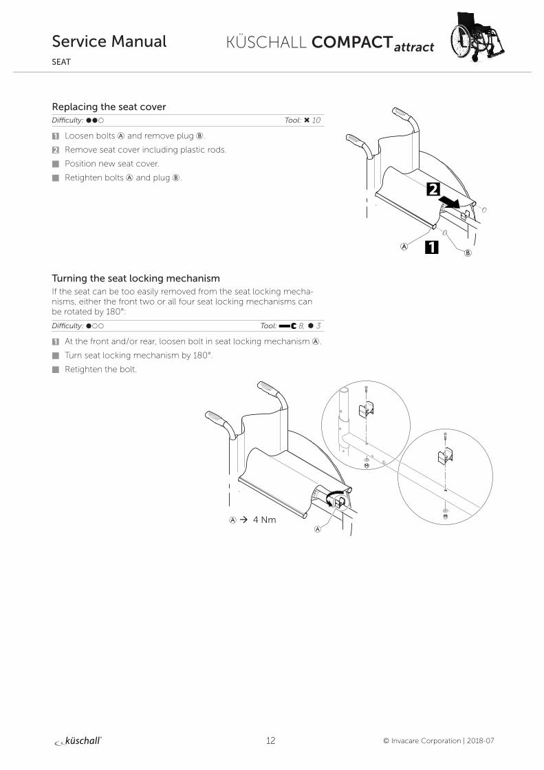
Replacing the seat coverDifficulty: ��� Tool: Ò 10
1 Loosen bolts A and remove plug B.
2 Remove seat cover including plastic rods.
Position new seat cover.
Retighten bolts A and plug B.
Turning the seat locking mechanismIf the seat can be too easily removed from the seat locking mecha-nisms, either the front two or all four seat locking mechanisms can be rotated by 180°:
Difficulty: ��� Tool: 8, à 3
1 At the front and/or rear, loosen bolt in seat locking mechanism A.
Turn seat locking mechanism by 180°.
Retighten the bolt.
A à 4 Nm
13
KÜSCHALL COMPACT attract
© Invacare Corporation | 2018-07
Service ManualBACKREST
BACKREST
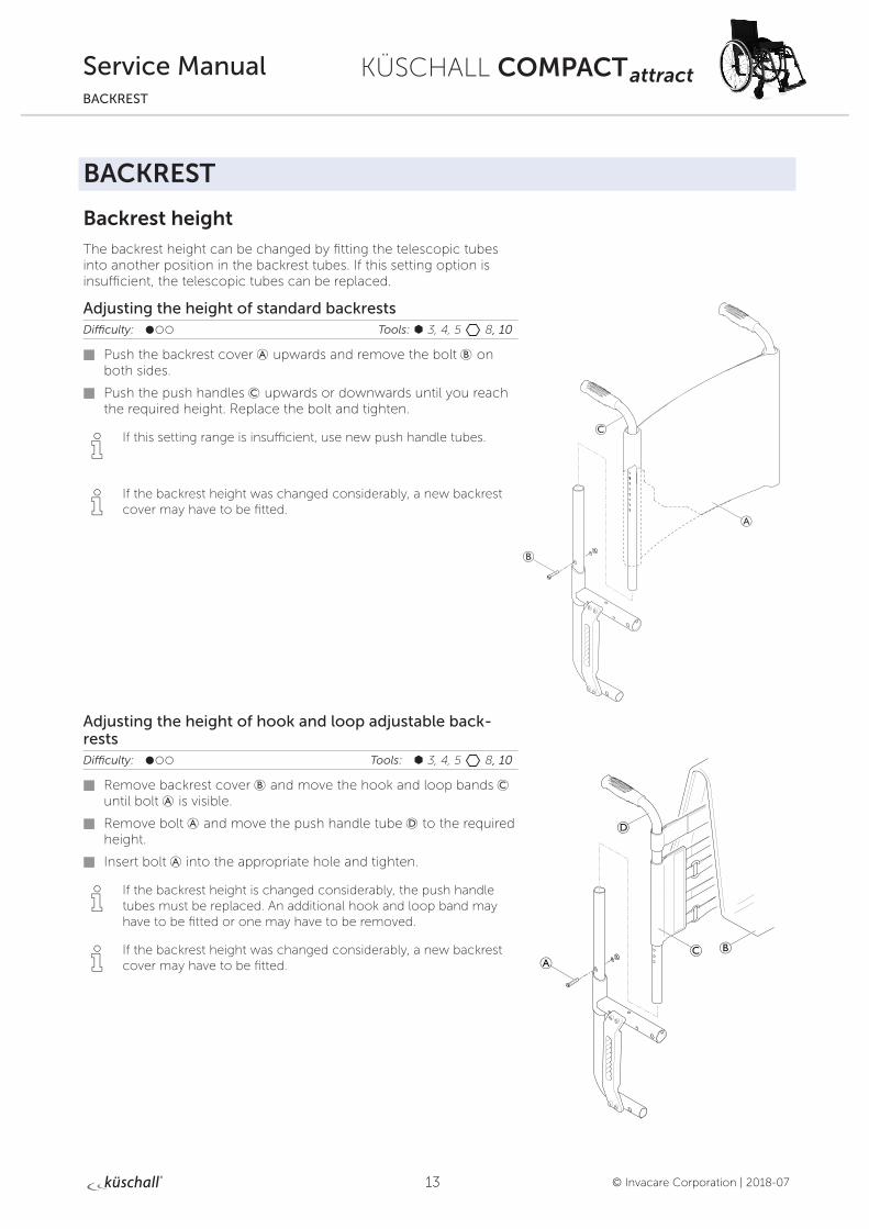
Backrest height
The backrest height can be changed by fitting the telescopic tubes into another position in the backrest tubes. If this setting option is insufficient, the telescopic tubes can be replaced.
Adjusting the height of standard backrestsDifficulty: ��� Tools: à 3, 4, 5 8, 10
Push the backrest cover A upwards and remove the bolt B on both sides.
Push the push handles C upwards or downwards until you reach the required height. Replace the bolt and tighten.
i If this setting range is insufficient, use new push handle tubes.
i If the backrest height was changed considerably, a new backrest cover may have to be fitted.
Adjusting the height of hook and loop adjustable back-restsDifficulty: ��� Tools: à 3, 4, 5 8, 10
Remove backrest cover B and move the hook and loop bands C until bolt A is visible.
Remove bolt A and move the push handle tube D to the required height.
Insert bolt A into the appropriate hole and tighten.
i If the backrest height is changed considerably, the push handle tubes must be replaced. An additional hook and loop band may have to be fitted or one may have to be removed.
i If the backrest height was changed considerably, a new backrest cover may have to be fitted.
14
KÜSCHALL COMPACT attract
© Invacare Corporation | 2018-07
Service ManualBACKREST
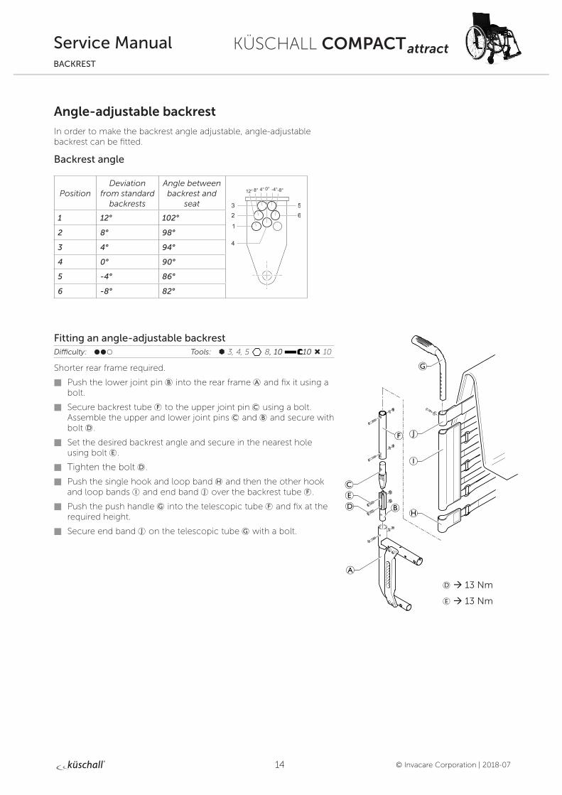
Angle-adjustable backrest
In order to make the backrest angle adjustable, angle-adjustable backrest can be fitted.
Backrest angle
PositionDeviation
from standard backrests
Angle between backrest and
seat
1 12° 102°
2 8° 98°
3 4° 94°
4 0° 90°
5 -4° 86°
6 -8° 82°
Fitting an angle-adjustable backrestDifficulty: ��� Tools: à 3, 4, 5 8, 10 10 Ò 10
Shorter rear frame required.
Push the lower joint pin B into the rear frame A and fix it using a bolt.
Secure backrest tube F to the upper joint pin C using a bolt. Assemble the upper and lower joint pins C and B and secure with bolt D.
Set the desired backrest angle and secure in the nearest hole using bolt E.
Tighten the bolt D.
Push the single hook and loop band H and then the other hook and loop bands I and end band J over the backrest tube F.
Push the push handle G into the telescopic tube F and fix at the required height.
Secure end band J on the telescopic tube G with a bolt.
D à 13 Nm
E à 13 Nm
15
KÜSCHALL COMPACT attract
© Invacare Corporation | 2018-07
Service ManualBACKREST
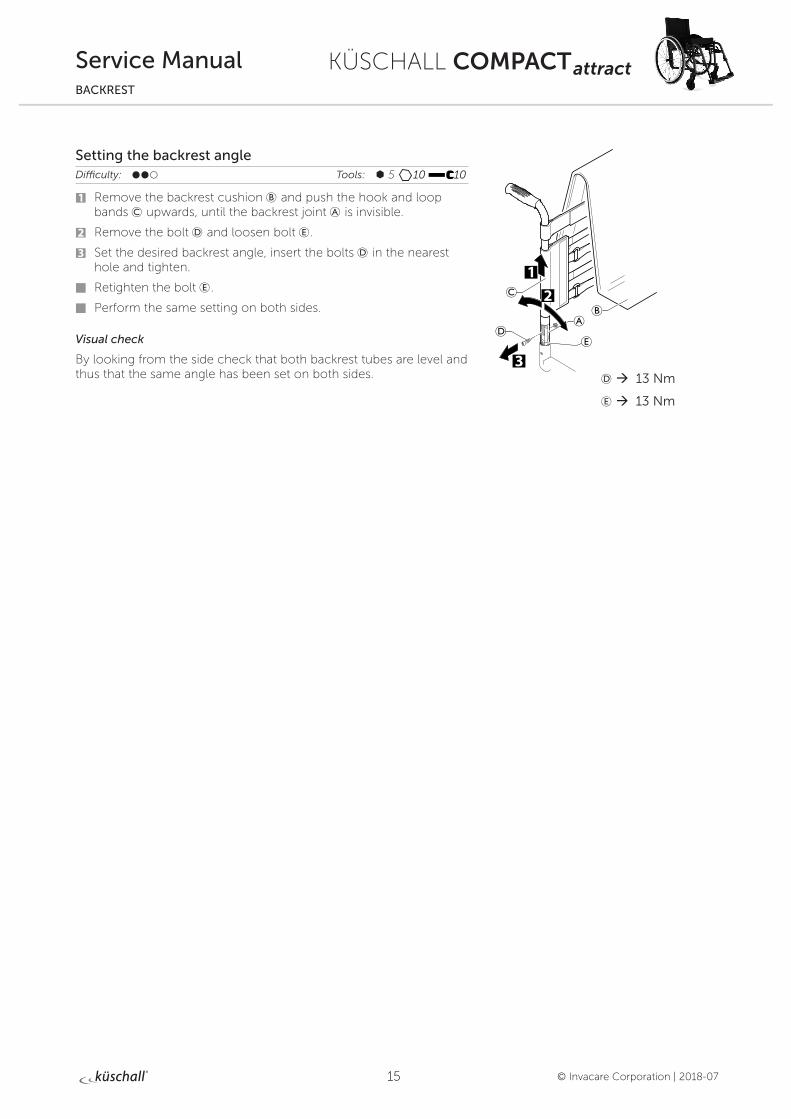
Setting the backrest angleDifficulty: ��� Tools: à 5 10 10
1 Remove the backrest cushion B and push the hook and loop bands C upwards, until the backrest joint A is invisible.
2 Remove the bolt D and loosen bolt E.
3 Set the desired backrest angle, insert the bolts D in the nearest hole and tighten.
Retighten the bolt E.
Perform the same setting on both sides.
Visual check
By looking from the side check that both backrest tubes are level and thus that the same angle has been set on both sides. D à 13 Nm
E à 13 Nm
16
KÜSCHALL COMPACT attract
© Invacare Corporation | 2018-07
Service ManualBACKREST
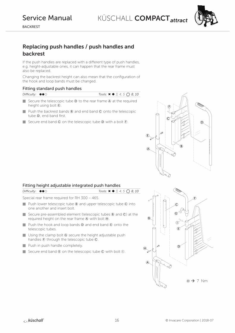
Replacing push handles / push handles and backrest
If the push handles are replaced with a different type of push handles, e.g. height-adjustable ones, it can happen that the rear frame must also be replaced.
Changing the backrest height can also mean that the configuration of the hook and loop bands must be changed.
Fitting standard push handlesDifficulty: ��� Tools: Ò Ã 3, 4, 5 8, 10
Secure the telescopic tube D to the rear frame A at the required height using bolt E.
Push the backrest bands B and end band C onto the telescopic tube D, end band first.
Secure end band C on the telescopic tube D with a bolt F.
Fitting height adjustable integrated push handlesDifficulty: ��� Tools: Ò Ã 3, 4, 5 8, 10
Special rear frame required for RH 300 – 465.
Push lower telescopic tube B and upper telescopic tube C into one another and insert bolt.
Secure pre-assembled element (telescopic tubes B and C) at the required height on the rear frame A with bolt H.
Push the hook and loop bands D and end band E onto the telescopic tubes.
Using the clamp bolt G secure the height adjustable push handles F through the telescopic tube C.
Push in push handle completely.
Secure end band E on the telescopic tube C with bolt I.
H à 7 Nm
17
KÜSCHALL COMPACT attract
© Invacare Corporation | 2018-07
Service ManualBACKREST
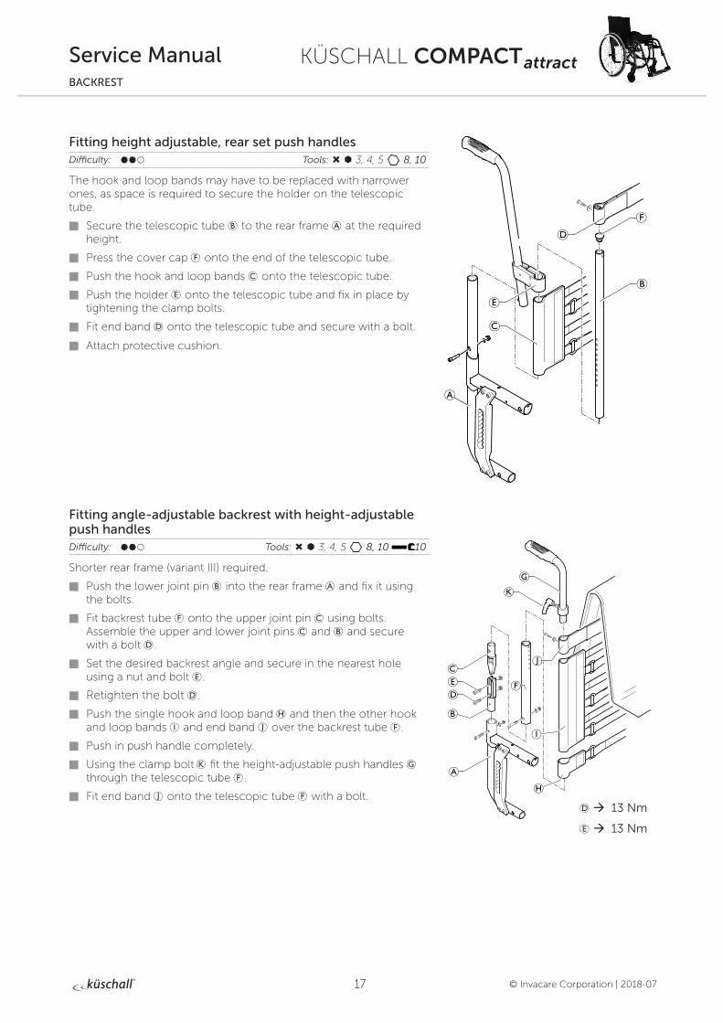
Fitting height adjustable, rear set push handles Difficulty: ��� Tools: Ò Ã 3, 4, 5 8, 10
The hook and loop bands may have to be replaced with narrower ones, as space is required to secure the holder on the telescopic tube.
Secure the telescopic tube B to the rear frame A at the required height.
Press the cover cap F onto the end of the telescopic tube.
Push the hook and loop bands C onto the telescopic tube.
Push the holder E onto the telescopic tube and fix in place by tightening the clamp bolts.
Fit end band D onto the telescopic tube and secure with a bolt.
Attach protective cushion.
Fitting angle-adjustable backrest with height-adjustable push handles Difficulty: ��� Tools: Ò Ã 3, 4, 5 8, 10 10
Shorter rear frame (variant III) required.
Push the lower joint pin B into the rear frame A and fix it using the bolts.
Fit backrest tube F onto the upper joint pin C using bolts. Assemble the upper and lower joint pins C and B and secure with a bolt D.
Set the desired backrest angle and secure in the nearest hole using a nut and bolt E.
Retighten the bolt D.
Push the single hook and loop band H and then the other hook and loop bands I and end band J over the backrest tube F.
Push in push handle completely.
Using the clamp bolt K fit the height-adjustable push handles G through the telescopic tube F.
Fit end band J onto the telescopic tube F with a bolt.D à 13 Nm
E à 13 Nm
18
KÜSCHALL COMPACT attract
© Invacare Corporation | 2018-07
Service ManualBACKREST
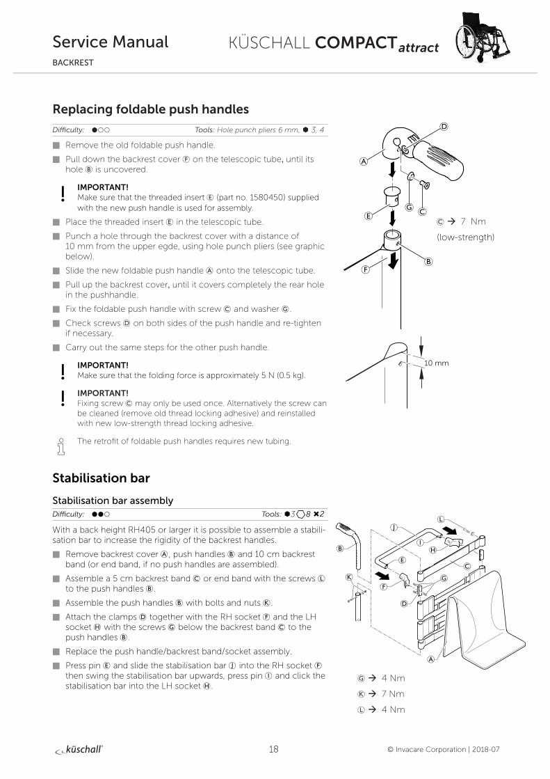
Replacing foldable push handles
Difficulty: ��� Tools: Hole punch pliers 6 mm, à 3, 4
Remove the old foldable push handle.
Pull down the backrest cover F on the telescopic tube, until its hole B is uncovered.
IMPORTANT! Make sure that the threaded insert E (part no. 1580450) supplied with the new push handle is used for assembly.
Place the threaded insert E in the telescopic tube.
Punch a hole through the backrest cover with a distance of 10 mm from the upper egde, using hole punch pliers (see graphic below).
Slide the new foldable push handle A onto the telescopic tube.
Pull up the backrest cover, until it covers completely the rear hole in the pushhandle.
Fix the foldable push handle with screw C and washer G.
Check screws D on both sides of the push handle and re-tighten if necessary.
Carry out the same steps for the other push handle.
IMPORTANT! Make sure that the folding force is approximately 5 N (0.5 kg).
IMPORTANT! Fixing screw C may only be used once. Alternatively the screw can be cleaned (remove old thread locking adhesive) and reinstalled with new low-strength thread locking adhesive.
i The retrofit of foldable push handles requires new tubing.
Stabilisation bar
Stabilisation bar assemblyDifficulty: ��� Tools: Ã3 8 Ò2
With a back height RH405 or larger it is possible to assemble a stabili-sation bar to increase the rigidity of the backrest handles.
Remove backrest cover A, push handles B and 10 cm backrest band (or end band, if no push handles are assembled).
Assemble a 5 cm backrest band C or end band with the screws L to the push handles B.
Assemble the push handles B with bolts and nuts K.
Attach the clamps D together with the RH socket F and the LH socket H with the screws G below the backrest band C to the push handles B.
Replace the push handle/backrest band/socket assembly.
Press pin E and slide the stabilisation bar J into the RH socket F then swing the stabilisation bar upwards, press pin I and click the stabilisation bar into the LH socket H.
C à 7 Nm
(low-strength)
G à 4 Nm
K à 7 Nm
L à 4 Nm
10 mm
19
KÜSCHALL COMPACT attract
© Invacare Corporation | 2018-07
Service ManualBACKREST
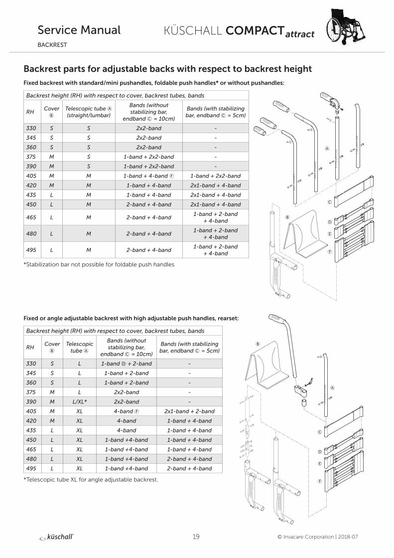
Backrest parts for adjustable backs with respect to backrest height
Fixed backrest with standard/mini pushandles, foldable push handles* or without pushandles:
Backrest height (RH) with respect to cover, backrest tubes, bands
RHCover
BTelescopic tube A (straight/lumbar)
Bands (without stabilizing bar,
endband C = 10cm)
Bands (with stabilizing bar, endband C = 5cm)
330 S S 2x2-band -
345 S S 2x2-band -
360 S S 2x2-band -
375 M S 1-band + 2x2-band -
390 M S 1-band + 2x2-band -
405 M M 1-band + 4-band F 1-band + 2x2-band
420 M M 1-band + 4-band 2x1-band + 4-band
435 L M 1-band + 4-band 2x1-band + 4-band
450 L M 2-band + 4-band 2x1-band + 4-band
465 L M 2-band + 4-band1-band + 2-band
+ 4-band
480 L M 2-band + 4-band1-band + 2-band
+ 4-band
495 L M 2-band + 4-band1-band + 2-band
+ 4-band
*Stabilization bar not possible for foldable push handles
Fixed or angle adjustable backrest with high adjustable push handles, rearset:
Backrest height (RH) with respect to cover, backrest tubes, bands
RHCover
BTelescopic
tube A
Bands (without stabilizing bar,
endband C = 10cm)
Bands (with stabilizing bar, endband C = 5cm)
330 S L 1-band D + 2-band -
345 S L 1-band + 2-band -
360 S L 1-band + 2-band -
375 M L 2x2-band -
390 M L/XL* 2x2-band -
405 M XL 4-band F 2x1-band + 2-band
420 M XL 4-band 1-band + 4-band
435 L XL 4-band 1-band + 4-band
450 L XL 1-band +4-band 1-band + 4-band
465 L XL 1-band +4-band 1-band + 4-band
480 L XL 1-band +4-band 2-band + 4-band
495 L XL 1-band +4-band 2-band + 4-band
*Telescopic tube XL for angle adjustable backrest.
20
KÜSCHALL COMPACT attract
© Invacare Corporation | 2018-07
Service ManualBACKREST
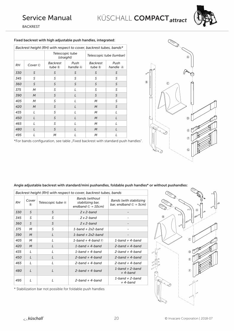
Fixed backrest with high adjustable push handles, integrated:
Backrest height (RH) with respect to cover, backrest tubes, bands*
Telescopic tube (straight)
Telescopic tube (lumbar)
RH Cover CBackrest tube B
Push handle A
Backrest tube B
Push handle A
330 S S S S S
345 S S S S S
360 S S S S S
375 M S L S S
390 M S L S S
405 M S L M S
420 M S L M S
435 L S L M L
450 L S L M L
465 L S L M L
480 L S L M L
495 L M L M L
*For bands configuration, see table „Fixed backrest with standard push handles“.
Angle adjustable backrest with standard/mini pushandles, foldable push handles* or without pushandles:
Backrest height (RH) with respect to cover, backrest tubes, bands
RHCover
BTelescopic tube A
Bands (without stabilizing bar,
endband C = 10cm)
Bands (with stabilizing bar, endband C = 5cm)
330 S S 2 x 2-band -
345 S S 2 x 2-band -
360 S S 2 x 2-band -
375 M S 1-band + 2x2-band -
390 M L 1-band + 2x2-band -
405 M L 1-band + 4-band F 1-band + 4-band
420 M L 1-band + 4-band 2-band + 4-band
435 L L 1-band + 4-band 2-band + 4-band
450 L L 2-band + 4-band 2-band + 4-band
465 L L 2-band + 4-band 2-band + 4-band
480 L L 2-band + 4-band1-band + 2-band
+ 4-band
495 L L 2-band + 4-band1-band + 2-band
+ 4-band
* Stabilization bar not possible for foldable push handles
21
KÜSCHALL COMPACT attract
© Invacare Corporation | 2018-07
Service ManualBACKREST
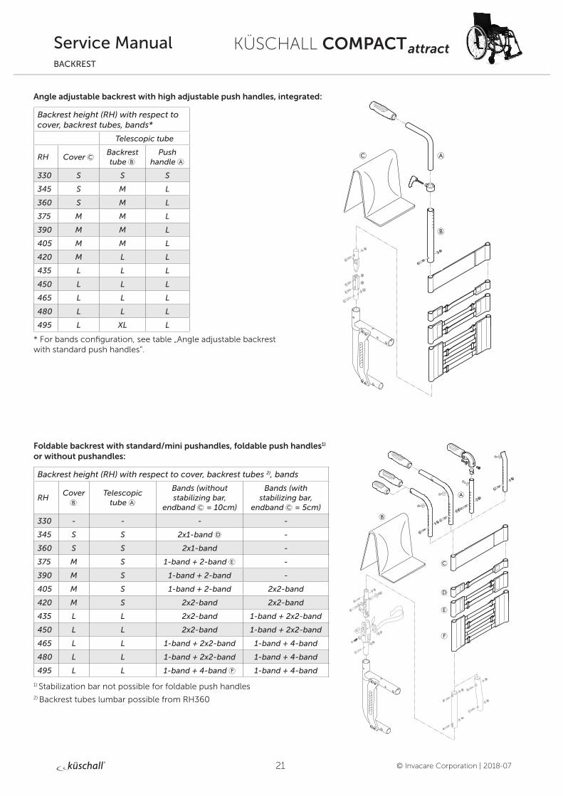
Angle adjustable backrest with high adjustable push handles, integrated:
Backrest height (RH) with respect to cover, backrest tubes, bands*
Telescopic tube
RH Cover CBackrest tube B
Push handle A
330 S S S
345 S M L
360 S M L
375 M M L
390 M M L
405 M M L
420 M L L
435 L L L
450 L L L
465 L L L
480 L L L
495 L XL L
* For bands configuration, see table „Angle adjustable backrest with standard push handles“.
Foldable backrest with standard/mini pushandles, foldable push handles1) or without pushandles:
Backrest height (RH) with respect to cover, backrest tubes 2), bands
RHCover
BTelescopic
tube A
Bands (without stabilizing bar,
endband C = 10cm)
Bands (with stabilizing bar,
endband C = 5cm)
330 - - - -
345 S S 2x1-band D -
360 S S 2x1-band -
375 M S 1-band + 2-band E -
390 M S 1-band + 2-band -
405 M S 1-band + 2-band 2x2-band
420 M S 2x2-band 2x2-band
435 L L 2x2-band 1-band + 2x2-band
450 L L 2x2-band 1-band + 2x2-band
465 L L 1-band + 2x2-band 1-band + 4-band
480 L L 1-band + 2x2-band 1-band + 4-band
495 L L 1-band + 4-band F 1-band + 4-band
1) Stabilization bar not possible for foldable push handles2) Backrest tubes lumbar possible from RH360
22
KÜSCHALL COMPACT attract
© Invacare Corporation | 2018-07
Service ManualBACKREST
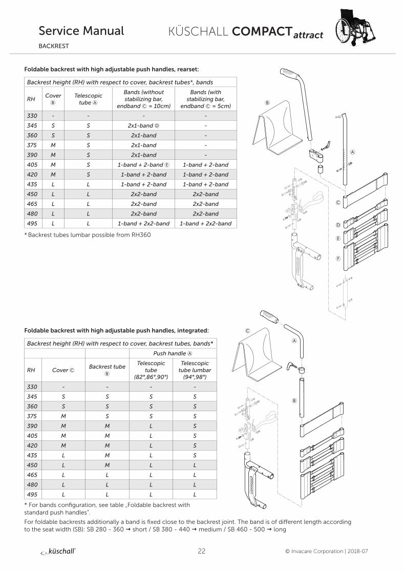
Foldable backrest with high adjustable push handles, rearset:
Backrest height (RH) with respect to cover, backrest tubes*, bands
RHCover
BTelescopic
tube A
Bands (without stabilizing bar,
endband C = 10cm)
Bands (with stabilizing bar,
endband C = 5cm)
330 - - - -
345 S S 2x1-band D -
360 S S 2x1-band -
375 M S 2x1-band -
390 M S 2x1-band -
405 M S 1-band + 2-band E 1-band + 2-band
420 M S 1-band + 2-band 1-band + 2-band
435 L L 1-band + 2-band 1-band + 2-band
450 L L 2x2-band 2x2-band
465 L L 2x2-band 2x2-band
480 L L 2x2-band 2x2-band
495 L L 1-band + 2x2-band 1-band + 2x2-band
* Backrest tubes lumbar possible from RH360
Foldable backrest with high adjustable push handles, integrated:
Backrest height (RH) with respect to cover, backrest tubes, bands*
Push handle A
RH Cover CBackrest tube
B
Telescopic tube
(82°,86°,90°)
Telescopic tube lumbar
(94°,98°)
330 - - - -
345 S S S S
360 S S S S
375 M S S S
390 M M L S
405 M M L S
420 M M L S
435 L M L S
450 L M L L
465 L L L L
480 L L L L
495 L L L L
* For bands configuration, see table „Foldable backrest with standard push handles“.
For foldable backrests additionally a band is fixed close to the backrest joint. The band is of different length according to the seat width (SB): SB 280 - 360 short / SB 380 - 440 medium / SB 460 - 500 long
23
KÜSCHALL COMPACT attract
© Invacare Corporation | 2018-07
Service ManualLEGRESTS
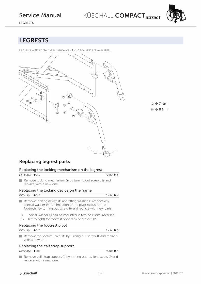
LEGRESTS
Legrests with angle measurements of 70° and 90° are available.
Replacing legrest parts
Replacing the locking mechanism on the legrestDifficulty: ��� Tools: ß 8
Remove locking mechanism A by turning out screws B and replace with a new one.
Replacing the locking device on the frameDifficulty: ��� Tools: à 4
Remove locking device E and fitting washer F respectively special washer H (for limitation of the pivot radius for the footrests) by turning out screw G and replace with new parts.
i Special washer H can be mounted in two positions (reversed left to right) for footrest pivot radii of 30° or 50°.
Replacing the footrest pivotDifficulty: ��� Tools: à 5
Remove the footrest pivot C by turning out screw D and replace with a new one.
Replacing the calf strap supportDifficulty: ��� Tools: à 5
Remove calf strap support I by turning out resilient screw J and replace with a new one.
D à 7 Nm
G à 8 Nm
24
KÜSCHALL COMPACT attract
© Invacare Corporation | 2018-07
Service ManualFOOTRESTS
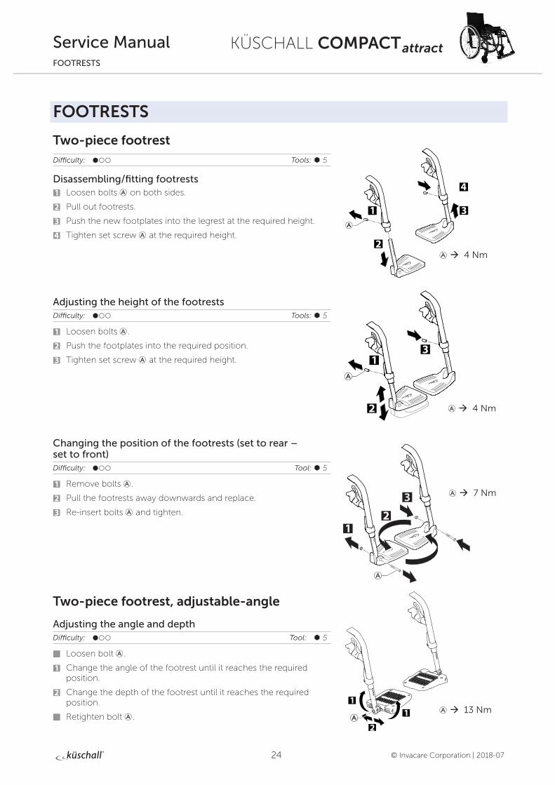
FOOTRESTS
Two-piece footrestDifficulty: ��� Tools: à 5
Disassembling/fitting footrests1 Loosen bolts A on both sides.
2 Pull out footrests.
3 Push the new footplates into the legrest at the required height.
4 Tighten set screw A at the required height.
Adjusting the height of the footrestsDifficulty: ��� Tools: à 5
1 Loosen bolts A.
2 Push the footplates into the required position.
3 Tighten set screw A at the required height.
Changing the position of the footrests (set to rear – set to front) Difficulty: ��� Tool: à 5
1 Remove bolts A.
2 Pull the footrests away downwards and replace.
3 Re-insert bolts A and tighten.
Two-piece footrest, adjustable-angle
Adjusting the angle and depthDifficulty: ��� Tool: à 5
Loosen bolt A.
1 Change the angle of the footrest until it reaches the required position.
2 Change the depth of the footrest until it reaches the required position.
Retighten bolt A.
A à 4 Nm
A à 4 Nm
A à 7 Nm
A à 13 Nm
25
KÜSCHALL COMPACT attract
© Invacare Corporation | 2018-07
Service ManualSIDE PARTS
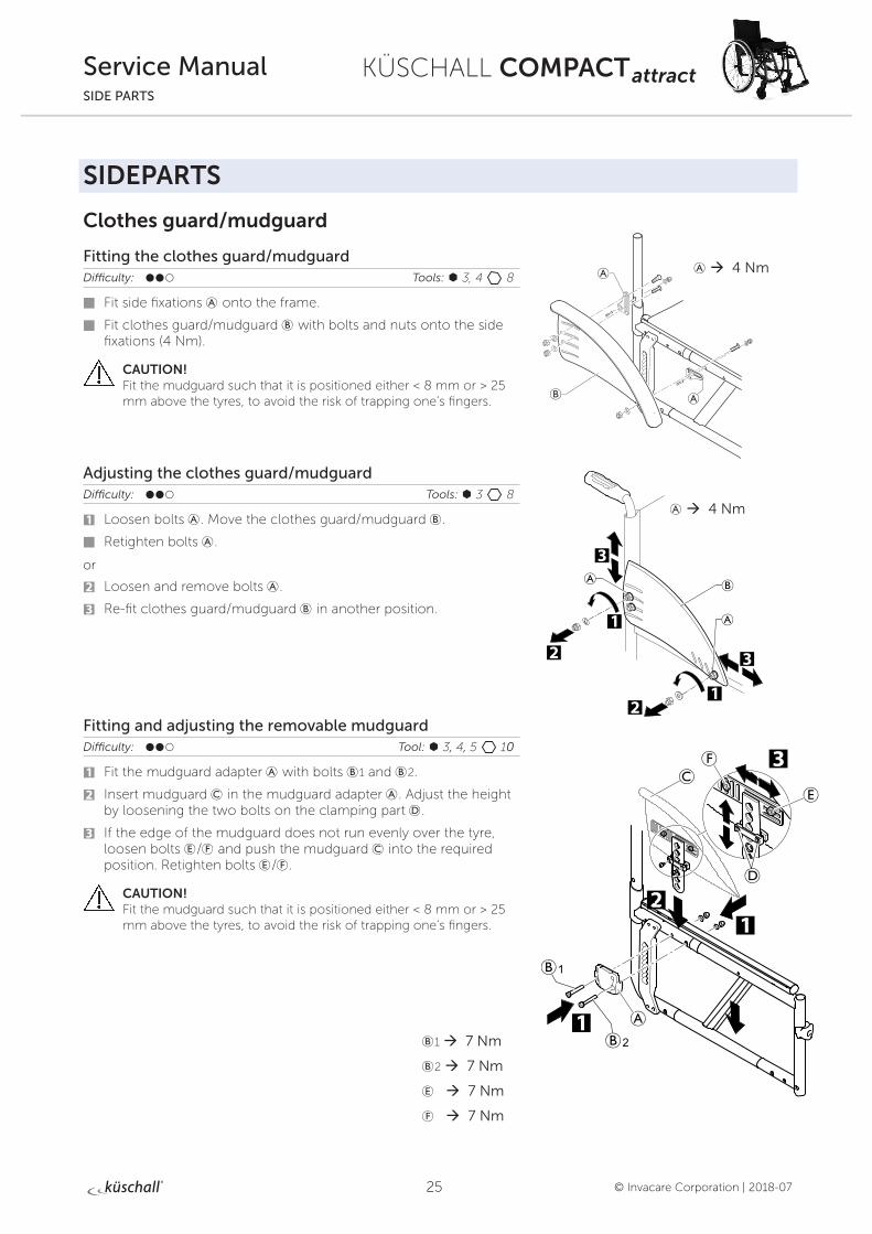
SIDEPARTS
Clothes guard/mudguard
Fitting the clothes guard/mudguardDifficulty: ��� Tools: à 3, 4 8
Fit side fixations A onto the frame.
Fit clothes guard/mudguard B with bolts and nuts onto the side fixations (4 Nm).
CAUTION! Fit the mudguard such that it is positioned either < 8 mm or > 25 mm above the tyres, to avoid the risk of trapping one’s fingers.
Adjusting the clothes guard/mudguardDifficulty: ��� Tools: à 3 8
1 Loosen bolts A. Move the clothes guard/mudguard B.
Retighten bolts A.
or
2 Loosen and remove bolts A.
3 Re-fit clothes guard/mudguard B in another position.
Fitting and adjusting the removable mudguardDifficulty: ��� Tool: à 3, 4, 5 10
1 Fit the mudguard adapter A with bolts B1 and B2.
2 Insert mudguard C in the mudguard adapter A. Adjust the height by loosening the two bolts on the clamping part D.
3 If the edge of the mudguard does not run evenly over the tyre, loosen bolts E/F and push the mudguard C into the required position. Retighten bolts E/F.
CAUTION! Fit the mudguard such that it is positioned either < 8 mm or > 25 mm above the tyres, to avoid the risk of trapping one’s fingers.
B1 à 7 Nm
B2 à 7 Nm
E à 7 Nm
F à 7 Nm
A à 4 Nm
A à 4 Nm
26
KÜSCHALL COMPACT attract
© Invacare Corporation | 2018-07
Service ManualSIDE PARTS
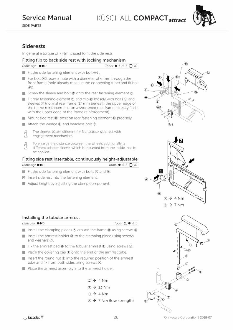
SiderestsIn general a torque of 7 Nm is used to fit the side rests.
Fitting flip to back side rest with locking mechanism Difficulty: ��� Tools: à 3, 4, 5 10
Fit the side fastening element with bolt A1 .
For bolt A2, bore a hole with a diameter of 6 mm through the front frame (hole already made in the connecting tube) and fit bolt A2.
Screw the sleeve and bolt B onto the rear fastening element C.
Fit rear fastening element C and clip G loosely with bolts H and sleeves I (normal rear frame: 17 mm beneath the upper edge of the frame reinforcement, on a shortened rear frame, directly flush with the upper edge of the frame reinforcement).
Mount side rest D, position rear fastening element C precisely.
Attach the wedge E and headless bolt F.
i The sleeves I are different for flip to back side rest with engagement mechanism.
i To enlarge the distance between the wheels additionally, a different adapter sleeve, which is mounted from the inside, has to be applied.
Fitting side rest insertable, continuously height-adjustable Difficulty: ��� Tools: à 4, 5 10
1 Fit the side fastening element with bolts A and B.
2 Insert side rest into the fastening element.
Adjust height by adjusting the clamp component.
Installing the tubular armrestDifficulty: ��� Tools: , à 4, 5
Install the clamping pieces A around the frame B using screws C.
Install the armrest holder D to the clamping piece using screws and washers E.
Fix the armrest pad G to the tubular armrest F using screws H.
Place the covering cap I onto the end of the armrest tube.
Insert the round nut J into the required position of the armrest tube and fix from both sides using screws K.
Place the armrest assembly into the armrest holder.
1
2
A à 4 Nm
B à 7 Nm
C à 4 Nm
E à 13 Nm
H à 4 Nm
K à 7 Nm (low strength)
27
KÜSCHALL COMPACT attract
© Invacare Corporation | 2018-07
Service ManualSIDE PARTS
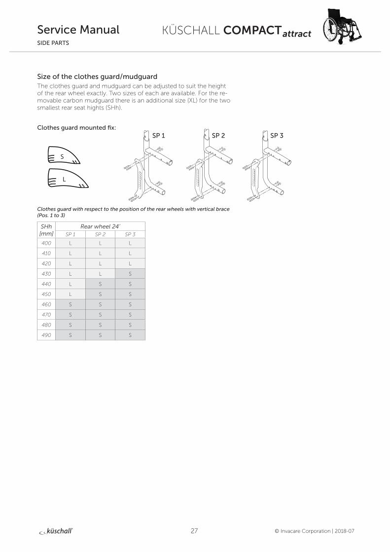
Size of the clothes guard/mudguard The clothes guard and mudguard can be adjusted to suit the height of the rear wheel exactly. Two sizes of each are available. For the re-movable carbon mudguard there is an additional size (XL) for the two smallest rear seat hights (SHh).
Clothes guard mounted fix:
Clothes guard with respect to the position of the rear wheels with vertical brace (Pos. 1 to 3)
SHh [mm]
Rear wheel 24’SP 1 SP 2 SP 3
400 L L L
410 L L L
420 L L L
430 L L S
440 L S S
450 L S S
460 S S S
470 S S S
480 S S S
490 S S S
L
S
SP 3SP 1 SP 2
28
KÜSCHALL COMPACT attract
© Invacare Corporation | 2018-07
Service ManualSIDE PARTS
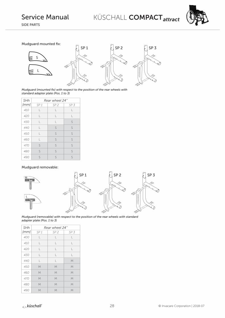
SHh [mm]
Rear wheel 24’’SP 1 SP 2 SP 3
400 L L L
410 L L L
420 L L L
430 L L L
440 L L M
450 M M M
460 M M M
470 M M M
480 M M M
490 M M M
L
S
SHh [mm]
Rear wheel 24’’SP 1 SP 2 SP 3
410 L L L
420 L L L
430 L L S
440 L S S
450 L S S
460 L S S
470 S S S
480 S S S
490 S S S
L
M
Mudguard mounted fix:
Mudguard (mounted fix) with respect to the position of the rear wheels with standard adapter plate (Pos. 1 to 3)
Mudguard removable:
Mudguard (removable) with respect to the position of the rear wheels with standard adapter plate (Pos. 1 to 3)
SP 3SP 1 SP 2
SP 3SP 1 SP 2

29
KÜSCHALL COMPACT attract
© Invacare Corporation | 2018-07
Service ManualSIDE PARTS
Fitting the küschall armrestMounting the armrest hardwear
Difficulty: ��� Tools: à 3, 4, 5 10
Insert nuts C and bolts B into the upper holes of the armrest holder A and carefully tighten. Do not squeeze the holder.
Mount the armrest holder A to the rear frame hole M using bolt F, sleeve E, washer and nut D.
Drill holes N with a diameter of 6 mm through the front frame by inserting the drill bit through the free hole of the pre-mounted armrest holder A.
Insert bolt H and tighten with washer and nut G.
Grease the pin P and Insert it with the spring O into the inner hole of clamping part K and place it around the reinforced part L of the rear frame.
Place the mating clamping part J around the rear frame and fix in true alignement with washers and bolts I.
Installing/Removing the armrest, T-armrest pad and cover
Installing
1 Install the armrest cover to the armrest assembly.
2 Insert the armrest assembly into the joint K and swivel it downwards so that it engages into the armrest holder A.
3 Install the T-armrest pad Q to the armrest assembly.
Removing
3 Remove the T-armrest pad from the armrest assembly.
4 Swivel the armrest assembly upwards out of the armrest holder A.
i On the backside of the joint pin R there is a tapped hole with a M5 stop screw S to define the stop of the armrest assembly when swivelling backwards. Adjust the stop screw as required.
5 Swivel the armrest assembly 45° outwards.
6 Lift the armrest assembly out of joint K.
D à 7 Nm
G à 7 Nm
I à 4 Nm
30
KÜSCHALL COMPACT attract
© Invacare Corporation | 2018-07
Service ManualFRONT WHEELS
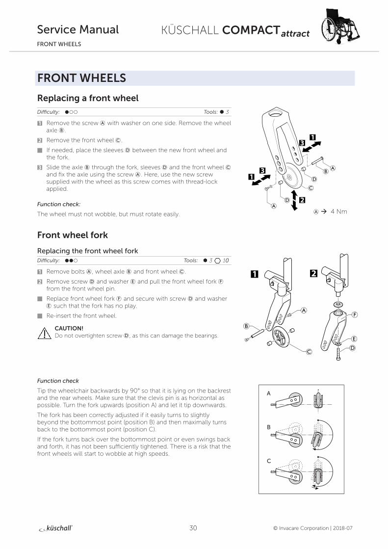
FRONT WHEELS
Replacing a front wheelDifficulty: ��� Tools: à 3
1 Remove the screw A with washer on one side. Remove the wheel axle B.
2 Remove the front wheel C.
If needed, place the sleeves D between the new front wheel and the fork.
3 Slide the axle B through the fork, sleeves D and the front wheel C and fix the axle using the screw A. Here, use the new screw supplied with the wheel as this screw comes with thread-lock applied.
Function check:
The wheel must not wobble, but must rotate easily.
Front wheel fork
Replacing the front wheel forkDifficulty: ��� Tools: à 3 10
1 Remove bolts A, wheel axle B and front wheel C.
2 Remove screw D and washer E and pull the front wheel fork F from the front wheel pin.
Replace front wheel fork F and secure with screw D and washer E such that the fork has no play.
Re-insert the front wheel.
CAUTION! Do not overtighten screw D, as this can damage the bearings.
Function check
Tip the wheelchair backwards by 90° so that it is lying on the backrest and the rear wheels. Make sure that the clevis pin is as horizontal as possible. Turn the fork upwards (position A) and let it tip downwards.
The fork has been correctly adjusted if it easily turns to slightly beyond the bottommost point (position B) and then maximally turns back to the bottommost point (position C).
If the fork turns back over the bottommost point or even swings back and forth, it has not been sufficiently tightened. There is a risk that the front wheels will start to wobble at high speeds.
A à 4 Nm
A
B
C
31
KÜSCHALL COMPACT attract
© Invacare Corporation | 2018-07
Service ManualFRONT WHEELS
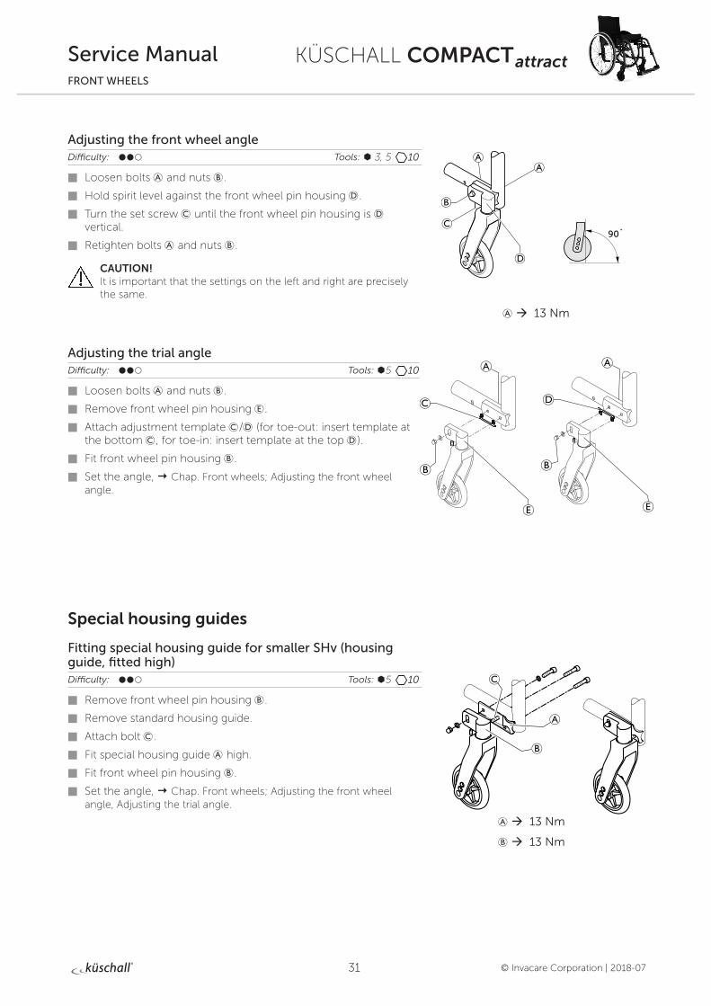
Adjusting the front wheel angleDifficulty: ��� Tools: à 3, 5 10
Loosen bolts A and nuts B.
Hold spirit level against the front wheel pin housing D.
Turn the set screw C until the front wheel pin housing is D vertical.
Retighten bolts A and nuts B.
CAUTION! It is important that the settings on the left and right are precisely the same.
Adjusting the trial angleDifficulty: ��� Tools: Ã5 10
Loosen bolts A and nuts B.
Remove front wheel pin housing E.
Attach adjustment template C/D (for toe-out: insert template at the bottom C, for toe-in: insert template at the top D).
Fit front wheel pin housing B.
Set the angle, Chap. Front wheels; Adjusting the front wheel angle.
Special housing guides
Fitting special housing guide for smaller SHv (housing guide, fitted high)Difficulty: ��� Tools: Ã5 10
Remove front wheel pin housing B.
Remove standard housing guide.
Attach bolt C.
Fit special housing guide A high.
Fit front wheel pin housing B.
Set the angle, Chap. Front wheels; Adjusting the front wheel angle, Adjusting the trial angle.
A à 13 Nm
A à 13 Nm
B à 13 Nm
90˚
32
KÜSCHALL COMPACT attract
© Invacare Corporation | 2018-07
Service ManualREAR WHEELS
REAR WHEELS
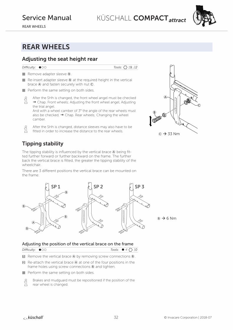
Adjusting the seat height rearDifficulty: ��� Tools: 19, 22
Remove adapter sleeve B.
Re-insert adapter sleeve B at the required height in the vertical brace A and fasten securely with nut C.
Perform the same setting on both sides.
i After the SHh is changed, the front wheel angel must be checked Chap. Front wheels; Adjusting the front wheel angel, Adjusting the trial angel. And with a wheel camber of 3° the angle of the rear wheels must also be checked, Chap. Rear wheels; Changing the wheel camber.
i After the SHh is changed, distance sleeves may also have to be fitted in order to increase the distance to the rear wheels.
Tipping stability
The tipping stability is influenced by the vertical brace A being fit-ted further forward or further backward on the frame. The further back the vertical brace is fitted, the greater the tipping stability of the wheelchair.
There are 3 different positions the vertical brace can be mounted on the frame:
SP 2 SP 3SP 1
Adjusting the position of the vertical brace on the frameDifficulty: ��� Tools: à 4 10
1 Remove the vertical brace A by removing screw connections B.
2 Re-attach the vertical brace A at one of the four positions in the frame holes using screw connections B and tighten.
Perform the same setting on both sides.
i Brakes and mudguard must be repositioned if the position of the rear wheel is changed.
C à 33 Nm
B à 6 Nm
33
KÜSCHALL COMPACT attract
© Invacare Corporation | 2018-07
Service ManualREAR WHEELS
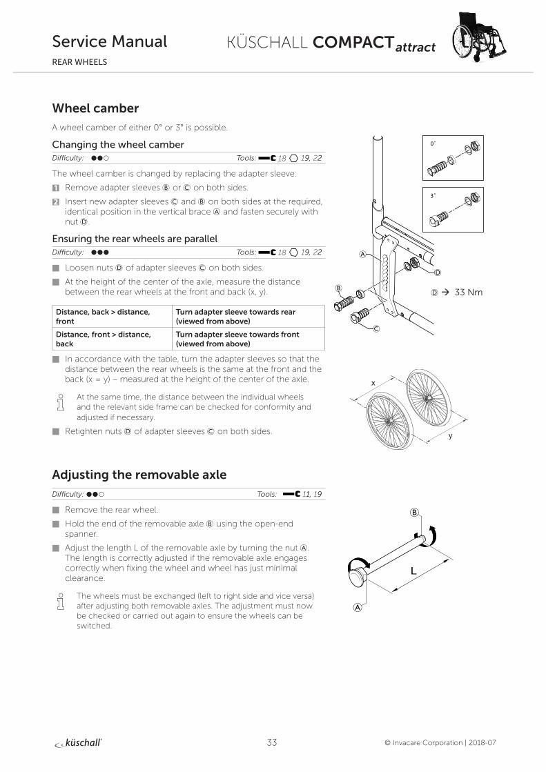
Wheel camber
A wheel camber of either 0° or 3° is possible.
Changing the wheel camberDifficulty: ��� Tools: 18 19, 22
The wheel camber is changed by replacing the adapter sleeve:
1 Remove adapter sleeves B or C on both sides.
2 Insert new adapter sleeves C and B on both sides at the required, identical position in the vertical brace A and fasten securely with nut D.
Ensuring the rear wheels are parallelDifficulty: ��� Tools: 18 19, 22
Loosen nuts D of adapter sleeves C on both sides.
At the height of the center of the axle, measure the distance between the rear wheels at the front and back (x, y).
Distance, back > distance, front
Turn adapter sleeve towards rear (viewed from above)
Distance, front > distance, back
Turn adapter sleeve towards front (viewed from above)
In accordance with the table, turn the adapter sleeves so that the distance between the rear wheels is the same at the front and the back (x = y) – measured at the height of the center of the axle.
i At the same time, the distance between the individual wheels and the relevant side frame can be checked for conformity and adjusted if necessary.
Retighten nuts D of adapter sleeves C on both sides.
Adjusting the removable axleDifficulty: ��� Tools: 11, 19
Remove the rear wheel.
Hold the end of the removable axle B using the open-end spanner.
Adjust the length L of the removable axle by turning the nut A. The length is correctly adjusted if the removable axle engages correctly when fixing the wheel and wheel has just minimal clearance.
i The wheels must be exchanged (left to right side and vice versa) after adjusting both removable axles. The adjustment must now be checked or carried out again to ensure the wheels can be switched.
0˚
3˚
D à 33 Nm
34
KÜSCHALL COMPACT attract
© Invacare Corporation | 2018-07
Service ManualREAR WHEELS
Repairing or changing an inner tubeDifficulty: ��� Tool: tire lever
Remove the rear wheel and release any air from the inner tube.
Lift one tire wall away from the rim using a bicycle tire lever. Do not use sharp objects such as a screwdriver which could damage the inner tube.
Pull the inner tube out of the tire
Repair the inner tube using a bicycle repair kit or, if necessary, replace the tube.
Inflate the tube slightly until it becomes round.
Insert the valve into the valve hole on the rim and place the tube inside the tire (the tube must lie right round the tire with no creases).
Starting close to the valve, push the tire wall over the edge of the rim using both hands. When doing this, check all the way round to ensure that the inner tube is not trapped between the tire and the rim.
Inflate the tube to its maximum operating pressure, Table, chap. Rear wheels, Checking the tire pressure. Check that no air is escaping from the tire.
Repairing or changing a solid tireSolid tires must be fitted by a qualified technician.
35
KÜSCHALL COMPACT attract
© Invacare Corporation | 2018-07
Service ManualBRAKES
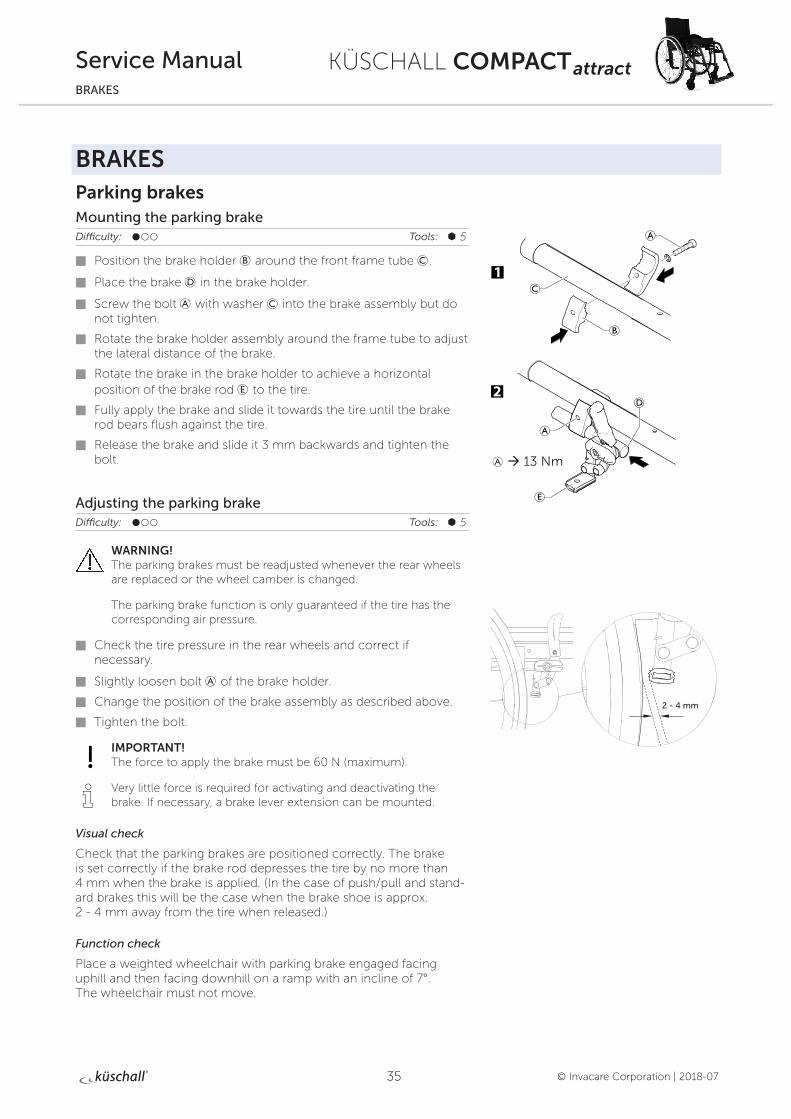
BRAKESParking brakesMounting the parking brakeDifficulty: ��� Tools: à 5
Position the brake holder B around the front frame tube C.
Place the brake D in the brake holder.
Screw the bolt A with washer C into the brake assembly but do not tighten.
Rotate the brake holder assembly around the frame tube to adjust the lateral distance of the brake.
Rotate the brake in the brake holder to achieve a horizontal position of the brake rod E to the tire.
Fully apply the brake and slide it towards the tire until the brake rod bears flush against the tire.
Release the brake and slide it 3 mm backwards and tighten the bolt.
Adjusting the parking brakeDifficulty: ��� Tools: à 5
WARNING! The parking brakes must be readjusted whenever the rear wheels are replaced or the wheel camber is changed.
The parking brake function is only guaranteed if the tire has the corresponding air pressure.
Check the tire pressure in the rear wheels and correct if necessary.
Slightly loosen bolt A of the brake holder.
Change the position of the brake assembly as described above.
Tighten the bolt.
IMPORTANT! The force to apply the brake must be 60 N (maximum).
i Very little force is required for activating and deactivating the brake. If necessary, a brake lever extension can be mounted.
Visual check
Check that the parking brakes are positioned correctly. The brake is set correctly if the brake rod depresses the tire by no more than 4 mm when the brake is applied. (In the case of push/pull and stand-ard brakes this will be the case when the brake shoe is approx. 2 - 4 mm away from the tire when released.)
Function check
Place a weighted wheelchair with parking brake engaged facing uphill and then facing downhill on a ramp with an incline of 7°. The wheelchair must not move.
A à 13 Nm
2 - 4 mm
36
KÜSCHALL COMPACT attract
© Invacare Corporation | 2018-07
Service ManualBRAKES
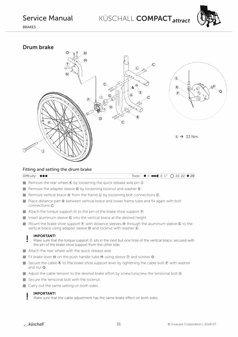
Drum brake
Fitting and setting the drum brake
Difficulty: ��� Tools: à 4 8, 17 10, 22, ß 20
Remove the rear wheel K by loosening the quick release axle pin J.
Remove the adapter sleeve D by loosening locknut and washer E.
Remove vertical brace A from the frame L by loosening bolt connections C.
Place distance part B between vertical brace and lower frame tube and fix again with bolt connections C.
Attach the torque support I to the pin of the brake shoe support F.
Insert aluminum sleeve G into the vertical brace at the desired height.
Mount the brake shoe support F with distance sleeves H through the aluminum sleeve G to the vertical brace using adapter sleeve D and locknut with washer E.
IMPORTANT! Make sure that the torque support I sits in the next but one hole of the vertical brace, secured with the pin of the brake shoe support from the other side.
Attach the rear wheel with the quick release axle.
Fit brake lever N on the push handle tube M using sleeve T and screws O.
Secure the cable R to the brake shoe support lever by tightening the cable bolt P with washer and nut Q.
Adjust the cable tension to the desired brake effort by screw/unscrew the tensional bolt S.
Secure the tensional bolt with the locknut.
Carry out the same setting on both sides.
IMPORTANT! Make sure that the cable adjustment has the same brake effect on both sides.
E à 33 Nm
37
KÜSCHALL COMPACT attract
© Invacare Corporation | 2018-07
Service ManualOPTIONS & ACCESSORIES
OPTIONS & ACCESSORIES
Antitipper
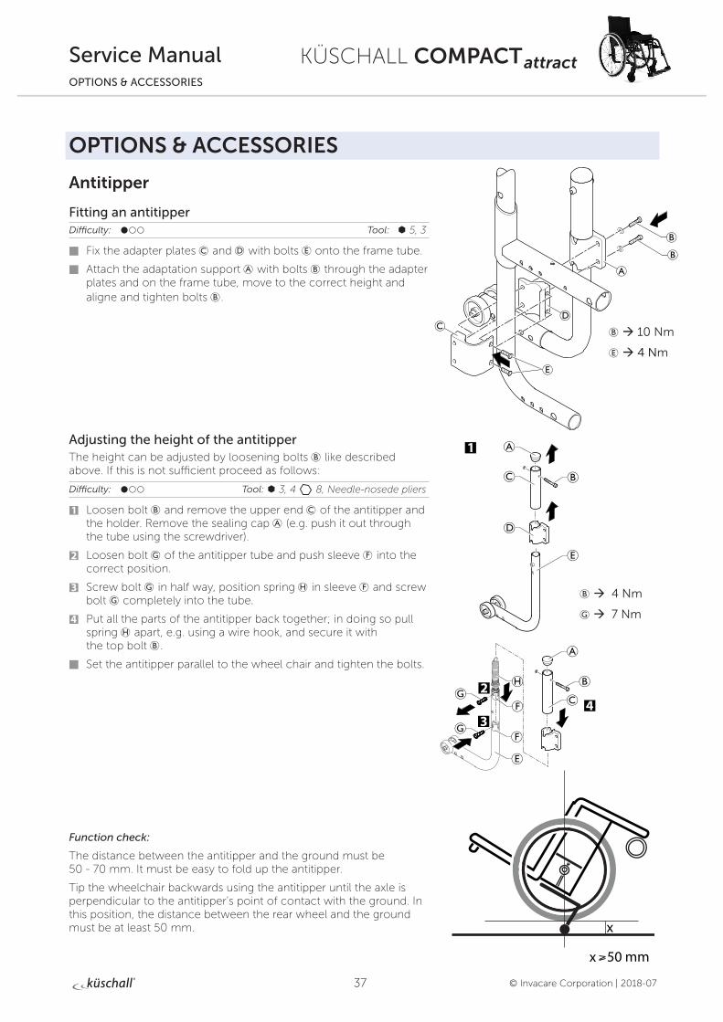
Fitting an antitipperDifficulty: ��� Tool: à 5, 3
Fix the adapter plates C and D with bolts E onto the frame tube.
Attach the adaptation support A with bolts B through the adapter plates and on the frame tube, move to the correct height and aligne and tighten bolts B.
Adjusting the height of the antitipperThe height can be adjusted by loosening bolts B like described above. If this is not sufficient proceed as follows:
Difficulty: ��� Tool: à 3, 4 8, Needle-nosede pliers
1 Loosen bolt B and remove the upper end C of the antitipper and the holder. Remove the sealing cap A (e.g. push it out through the tube using the screwdriver).
2 Loosen bolt G of the antitipper tube and push sleeve F into the correct position.
3 Screw bolt G in half way, position spring H in sleeve F and screw bolt G completely into the tube.
4 Put all the parts of the antitipper back together; in doing so pull spring H apart, e.g. using a wire hook, and secure it with the top bolt B.
Set the antitipper parallel to the wheel chair and tighten the bolts.
Function check:
The distance between the antitipper and the ground must be 50 - 70 mm. It must be easy to fold up the antitipper.
Tip the wheelchair backwards using the antitipper until the axle is perpendicular to the antitipper’s point of contact with the ground. In this position, the distance between the rear wheel and the ground must be at least 50 mm. x
x 50 mm
B à 4 Nm
G à 7 Nm
B à 10 Nm
E à 4 Nm
38
KÜSCHALL COMPACT attract
© Invacare Corporation | 2018-07
Service ManualOPTIONS & ACCESSORIES
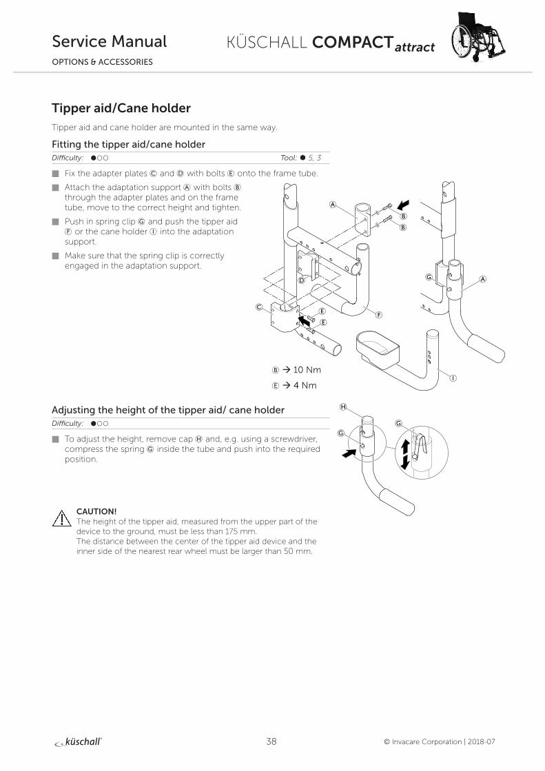
Tipper aid/Cane holder
Tipper aid and cane holder are mounted in the same way.
Fitting the tipper aid/cane holderDifficulty: ��� Tool: à 5, 3
Fix the adapter plates C and D with bolts E onto the frame tube.
Attach the adaptation support A with bolts B through the adapter plates and on the frame tube, move to the correct height and tighten.
Push in spring clip G and push the tipper aid F or the cane holder I into the adaptation support.
Make sure that the spring clip is correctly engaged in the adaptation support.
Adjusting the height of the tipper aid/ cane holderDifficulty: ���
To adjust the height, remove cap H and, e.g. using a screwdriver, compress the spring G inside the tube and push into the required position.
CAUTION! The height of the tipper aid, measured from the upper part of the device to the ground, must be less than 175 mm. The distance between the center of the tipper aid device and the inner side of the nearest rear wheel must be larger than 50 mm.
B à 10 Nm
E à 4 Nm
39
KÜSCHALL COMPACT attract
© Invacare Corporation | 2018-07
Service ManualOPTIONS & ACCESSORIES
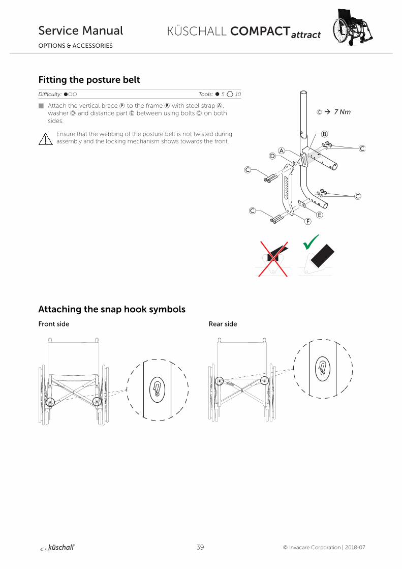
Fitting the posture belt
Difficulty: ��� Tools: à 5 10
Attach the vertical brace F to the frame B with steel strap A, washer D and distance part E between using bolts C on both sides.
Ensure that the webbing of the posture belt is not twisted during assembly and the locking mechanism shows towards the front.
Attaching the snap hook symbols
Front side Rear side
C à 7 Nm
Invacare France Operations
Route de St Roch
F–37230 Fondettes
France
© Invacare Corporation | 2018-07 | 1589082-D
Service Manual
KÜSCHALL COMPACT attract
ENGLISH | 2018-07
Invacare distributors:
Belgium & Luxemburg: Invacare nv • Autobaan 22 • B-8210 Loppem
Tel: (32) (0)50 83 10 10 • Fax: (32) (0)50 83 10 11 • [email protected] • www.invacare.be
Danmark: Invacare A/S • Sdr. Ringvej 37 • DK-2605 Brøndby
Tel: (45) (0)36 90 00 00 • Fax: (45) (0)36 90 00 01 • [email protected] • www.invacare.dk
Deutschland: Invacare GmbH • Alemannenstraße 10 • D-88316 Isny
Tel: (49) (0)75 62 7 00 0 • Fax: (49) (0)75 62 7 00 66 • [email protected] • www.invacare.de
Eastern Europe, Middle East & CIS: Invacare EU Export • Kleiststraße 49 • D-32457 Porta Westfalica
Tel: (49) (0)57 31 754 540 • Fax: (49) (0)57 31 754 541 • [email protected] • www.invacare-eu-export.com
España: Invacare SA • c/Areny s/n • Polígon Industrial de Celrà • E-17460 Celrà (Girona)
Tel: (34) (0)972 49 32 00 • Fax: (34) (0)972 49 32 20 • [email protected] • www.invacare.es
France: Invacare Poirier SAS • Route de St Roch • F-37230 Fondettes
Tel: (33) (0)2 47 62 64 66 • Fax: (33) (0)2 47 42 12 24 • [email protected] • www.invacare.fr
Ireland: Invacare Ireland Ltd • Unit 5 Seatown Business Campus • Seatown Road • Swords • County Dublin – Ireland
Tel : (353) 1 810 7084 • Fax: (353) 1 810 7085 • [email protected] • www.invacare.ie
Italia: Invacare Mecc San s.r.l. • Via dei Pini 62 • I-36016 Thiene (VI)
Tel: (39) 0445 38 00 59 • Fax: (39) 0445 38 00 34 • [email protected] • www.invacare.it
Nederland: Invacare BV • Galvanistraat 14-3 • NL-6716 AE Ede
Tel: (31) (0)318 695 757 • Fax: (31) (0)318 695 758 • [email protected] • www.invacare.nl
Norge: Invacare AS • Grensesvingen 9 • Postboks 6230 • Etterstad • N-0603 Oslo
Tel: (47) (0)22 57 95 00 • Fax: (47) (0)22 57 95 01 • [email protected] • [email protected] • www.invacare.no
Österreich: Invacare Austria GmbH • Herzog Odilostrasse 101 • A-5310 Mondsee
Tel.: (43) 6232 5535 0 • Fax.: (43) 6232 5535 4 • [email protected] • www.invacare.at
Portugal: Invacare Lda • Rua Estrada Velha • 949 • P-4465-784 Leça do Balio
Tel: (351) (0)225 1059 46/47 • Fax: (351) (0)225 1057 39 • [email protected] • www.invacare.pt
Sverige: Invacare AB • Fagerstagatan 9 • S-163 91 Spånga
Tel: (46) (0)8 761 70 90 • Fax: (46) (0)8 761 81 08 • [email protected] • [email protected] • www.invacare.se
Suomi: Camp Mobility • Patamäenkatu 5 • 33900 Tampere
Tel: 09-35076310 • [email protected] • www.campmobility.fi
Schweiz/Suisse/Svizzera: Invacare AG • Benkenstrasse 260 • CH-4108 Witterswil
Tel.: (41) (0)61 487 70 80 • Fax.: (41) (0)61 487 70 81 • [email protected] • www.invacare.ch
United Kingdom: Invacare Limited • Pencoed Technology Park,
Pencoed, Bridgend CF35 5AQ • Switchboard Tel: (44) (0)1656 776 200, Fax: (44) (0)1656 776 201 •
Customer services Tel: (44) (0) 1656 776 222 • Fax: (44) (0) 1656 776 220 • [email protected] • www.invacare.co.uk
Australia: Invacare Australia Pty Ltd • ABN 45 074 676 378, PO Box 5002, 1 Lenton Place, North Rocks, NSW 2151, Australia •
Freephone: 1800 069 042, Fax: 02 8839 5353 • E-mail: [email protected] • Web: www.invacare.com.au
New Zealand: Invacare New Zealand • PO Box 62–124, 4 Westfield Place, Mt. Wellington, Auckland, New Zealand •
Freephone: 8000 468 222, Freefax: 0800 807 788 • E-mail: [email protected] • Web: www.invacare.co.nz