kuka.gluetech 4 -...
TRANSCRIPT

KUKA System Technology
KUKA.GlueTech 4.1
For KUKA System Software 8.2
KUKA Roboter GmbH
Issued: 23.04.2012
Version: KST GlueTech 4.1 V2 en

KUKA.GlueTech 4.1
2 / 77 Issued: 23.04.2012 Version: KST GlueTech 4.1 V2 en
© Copyright 2012
KUKA Roboter GmbH
Zugspitzstraße 140
D-86165 Augsburg
Germany
This documentation or excerpts therefrom may not be reproduced or disclosed to third parties without the express permission of KUKA Roboter GmbH.
Other functions not described in this documentation may be operable in the controller. The user has no claims to these functions, however, in the case of a replacement or service work.
We have checked the content of this documentation for conformity with the hardware and software described. Nevertheless, discrepancies cannot be precluded, for which reason we are not able to guarantee total conformity. The information in this documentation is checked on a regular basis, how-ever, and necessary corrections will be incorporated in the subsequent edition.
Subject to technical alterations without an effect on the function.
Translation of the original documentation
KIM-PS5-DOC
Publication: Pub KST GlueTech 4.1 en
Bookstructure: KST GlueTech 4.1 V1.1
Version: KST GlueTech 4.1 V2 en
Contents
Contents
1 Introduction .................................................................................................. 5
1.1 Target group .............................................................................................................. 5
1.2 Industrial robot documentation ................................................................................... 5
1.3 Representation of warnings and notes ...................................................................... 5
1.4 Terms used ................................................................................................................ 6
2 Product description ..................................................................................... 7
2.1 Overview of KUKA.GlueTech ..................................................................................... 7
2.2 Functional principle .................................................................................................... 8
2.3 Switching points and delay times ............................................................................... 8
3 Safety ............................................................................................................ 11
4 Installation ................................................................................................... 13
4.1 System requirements ................................................................................................. 13
4.2 Installing or updating GlueTech ................................................................................. 13
4.3 Uninstalling GlueTech ................................................................................................ 13
5 Operation ...................................................................................................... 15
5.1 Menus ........................................................................................................................ 15
5.2 Status keys ................................................................................................................ 15
6 Configuration ............................................................................................... 17
6.1 Overview .................................................................................................................... 17
6.2 Configuring a cell ....................................................................................................... 17
6.3 Carrying out settings .................................................................................................. 18
6.4 Configuring outputs .................................................................................................... 19
6.5 Configuring inputs ...................................................................................................... 20
6.6 Manually configuring delay times ............................................................................... 21
6.7 Configuring seam data sets ....................................................................................... 22
6.8 Calibration routine ...................................................................................................... 23
6.8.1 Defining the path velocity ...................................................................................... 25
6.8.2 Testing the TCP .................................................................................................... 25
6.8.3 Determining the switching times of the nozzle (Gun On/Off) ................................ 25
6.8.4 Determining the material / air flow (Eq. Delay) ..................................................... 26
6.8.5 Determining the reaction time after a jump in the analog output (Ana. Switch) .... 26
6.8.6 Verifying and determining all configuration values (All) ........................................ 26
7 Programming ............................................................................................... 29
7.1 Overview of GlueTech motion commands ................................................................. 29
7.1.1 Inline form “GLUE ON LIN” ................................................................................... 29
7.1.2 Inline form “GLUE SWITCH LIN” .......................................................................... 30
7.1.3 Inline form “GLUE OFF LIN” ................................................................................. 31
7.1.4 Inline form “GLUE ON CIRC” ................................................................................ 32
7.1.5 Inline form “GLUE SWITCH CIRC” ....................................................................... 33
7.1.6 Inline form “GLUE OFF CIRC” .............................................................................. 34
7.1.7 Inline form “GLUE ON PTP” ................................................................................. 35
7.1.8 Inline form “GLUE OFF PTP” ................................................................................ 36
7.2 Overview of GlueTech Spline motion commands ...................................................... 37
3 / 77Issued: 23.04.2012 Version: KST GlueTech 4.1 V2 en

4 / 77
KUKA.GlueTech 4.1
7.2.1 Inline form “GLUE ON SPL” ................................................................................. 37
7.2.2 Inline form “GLUE SWITCH SPL” ......................................................................... 38
7.2.3 Inline form “GLUE OFF SPL” ................................................................................ 39
7.2.4 Inline form “GLUE ON SLIN” ................................................................................ 41
7.2.5 Inline form “GLUE SWITCH SLIN” ....................................................................... 41
7.2.6 Inline form “GLUE OFF SLIN” .............................................................................. 42
7.2.7 Inline form “GLUE ON SCIRC” ............................................................................. 43
7.2.8 Inline form “GLUE SWITCH SCIRC” .................................................................... 44
7.2.9 Inline form “GLUE OFF SCIRC” ........................................................................... 45
7.3 Overview of GlueTech dispensing instructions .......................................................... 46
7.3.1 Inline form “Init system” ........................................................................................ 47
7.3.2 Inline form “Set program number” ........................................................................ 48
7.3.3 Inline form “Set motion parameter” ....................................................................... 49
7.3.4 Inline form “Dispense complete” ........................................................................... 50
7.3.5 Inline form “Reload doser” .................................................................................... 51
7.3.6 Inline form “Error check” ....................................................................................... 52
7.4 Overview of GlueTech purge instructions .................................................................. 54
7.4.1 Inline form “Purge gun” ......................................................................................... 54
7.4.2 Inline form “Monitoring purge gun” ....................................................................... 55
7.4.3 Inline form “Enable purge” .................................................................................... 56
7.5 Teaching the purge position (MoveToPurge) ............................................................ 57
8 Example programs ...................................................................................... 59
8.1 Example program for dispensing ............................................................................... 59
8.2 Example program for dispensing with spline motion ................................................. 60
9 System variables ......................................................................................... 61
9.1 I/O interface variables ................................................................................................ 61
10 Messages ...................................................................................................... 65
11 KUKA Service ............................................................................................... 67
11.1 Requesting support ................................................................................................... 67
11.2 KUKA Customer Support ........................................................................................... 67
Index ............................................................................................................. 75
Issued: 23.04.2012 Version: KST GlueTech 4.1 V2 en

1 Introduction
1 Introduction
1.1 Target group
This documentation is aimed at users with the following knowledge and skills:
Advanced KRL programming skills
Advanced knowledge of the robot controller system
Advanced knowledge of the dispensing controller systems
Knowledge of field bus interfaces
1.2 Industrial robot documentation
The industrial robot documentation consists of the following parts:
Documentation for the manipulator
Documentation for the robot controller
Operating and programming instructions for the KUKA System Software
Documentation relating to options and accessories
Parts catalog on storage medium
Each of these sets of instructions is a separate document.
1.3 Representation of warnings and notes
Safety These warnings are relevant to safety and must be observed.
Notes These hints serve to make your work easier or contain references to further information.
For optimal use of our products, we recommend that our customers take part in a course of training at KUKA College. Information about the training program can be found at www.kuka.com or can be ob-
tained directly from our subsidiaries.
These warnings mean that it is certain or highly probable that death or severe physical injury will occur, if no pre-
cautions are taken.
These warnings mean that death or severe physical inju-ry may occur, if no precautions are taken.
These warnings mean that minor physical injuries may occur, if no precautions are taken.
These warnings mean that damage to property may oc-cur, if no precautions are taken.
These warnings contain references to safety-relevant information or general safety measures. These warnings do not refer to individual hazards or individual precautionary measures.
Tip to make your work easier or reference to further information.
5 / 77Issued: 23.04.2012 Version: KST GlueTech 4.1 V2 en

6 / 77
KUKA.GlueTech 4.1
1.4 Terms used
Term Description
Seam data set Data set with settings for speed and analog voltage for each seam.
Exact position-ing
Programmed position of the robot without approximate positioning. The robot stops at the position.
Handshaking Handshaking is a method used to check 2 devices dur-ing data transmission by means of direct acknowledge-ment signals.
Calibration rou-tine
The KUKA.GlueTech calibration routine sets various configuration values on a defined linear path.
Seam number The seam number uniquely specifies the seam.
Switching point The switching point defines the switching position of the nozzle.
Switching times The programmable switching times compensate for the delay time of the nozzle.
Purging Function for emptying the system (dispenser) and sub-sequent refilling.
Purge position Defined position for emptying the nozzle.
Motion parame-ters
Programmable parameters and machine data adapted specifically for the application of adhesives or similar substances.
Issued: 23.04.2012 Version: KST GlueTech 4.1 V2 en

2 Product description
2 Product description
2.1 Overview of KUKA.GlueTech
KUKA.GlueTech is an add-on technology package with the following func-tions:
Functions Staggered control of up to 3 dispensing controllers
Staggered control of up to 4 nozzles per dispensing controller
KRL commands for the creation of dispensing applications (inline forms)
Configuration of up to 20 different seam data sets
Calibration routine
Diverse settings (I/Os, PLC, etc.)
Areas of appli-
cation
Application of adhesive beads
Application of 1-component / 2-component adhesives
Bead shaping (electrical / pneumatic)
Thin-jet flatstream sealing
Extruded application of sound-insulating material
Communication The robot controller communicates with the dispensing controller via a field bus. There are different field bus cards for the robot controller. The field buses Interbus, PROFIBUS or PROFINET can be used.
GlueTech can be used for controlling an ASC 5000, SYS 300, SYS 3000, SYS 4000 and SYS 6000 (SCA Schucker) as well as for con-trolling a similar type of dispensing controller (for example, from Intec
Bielenberg, Rickert, Kleinmichel). KUKA Roboter GmbH must be consulted if a different dispensing controller is to be used (>>> 11 "KUKA Service" Page 67).
Fig. 2-1: Example of an adhesive bonding cell
1 Dispensing controller 5 Pump controller
2 Robot controller 6 Robot
3 PLC 7 Dispenser
4 Drum pump 8 Nozzle
7 / 77Issued: 23.04.2012 Version: KST GlueTech 4.1 V2 en

8 / 77
KUKA.GlueTech 4.1
2.2 Functional principle
Description KUKA.GlueTech can regulate the following parameters of the dispensing con-troller (depending on the settings) proportional to the path velocity (TCP), but also independently of the velocity:
Delivery rate of the material
Delivery rate of the air spray
The parameters are regulated via the analog voltage of the outputs. The out-puts are configured via the field bus of the robot controller.
2.3 Switching points and delay times
Description In the dispensing process, time delays and changes in the dispensing velocity occur at the switching points (Glue On, Glue Switch, Glue Off) between the ro-bot controller and the dispensing controller. This influences the material flow and the air supply. For this reason, the switching points must be adapted ac-cordingly.
Further information about Interbus, PROFIBUS or PROFINET can be found in the documentation for these field bus systems.
Fig. 2-2: Diagram: Analog voltage / speed
Issued: 23.04.2012 Version: KST GlueTech 4.1 V2 en

2 Product description
Example The following diagram shows a dispensing process with a straight seam. The angle of the nozzle to the workpiece should be between 70° and 90°, depend-ing on the application. The start point of the robot is P1. At the switching point On (Glue On LIN), the nozzle is switched on. The material flow begins after a delay.
At the switching point Off (Glue Off LIN), the nozzle is switched off. This ma-terial flow stops after a delay.
Fig. 2-3: Diagram: Delay times / offset
1 Material flow 5 Delay time
2 Air supply 6 Delay time
3 Robot motion 7 Offset
4 Delay time
Fig. 2-4: Switching points and delay times during the dispensing pro-cess
1, 2 Delay time
9 / 77Issued: 23.04.2012 Version: KST GlueTech 4.1 V2 en

10 / 77
KUKA.GlueTech 4.1
Issued: 23.04.2012 Version: KST GlueTech 4.1 V2 en

3 Safety
3 Safety
This documentation contains safety instructions which refer specifically to the software described here.
The fundamental safety information for the industrial robot can be found in the “Safety” chapter of the Operating and Programming Instructions for System In-tegrators or the Operating and Programming Instructions for End Users.
The “Safety” chapter in the operating and programming instructions must be observed. Death to persons, severe physical injuries or con-siderable damage to property may otherwise result.
11 / 77Issued: 23.04.2012 Version: KST GlueTech 4.1 V2 en

12 / 77
KUKA.GlueTech 4.1
Issued: 23.04.2012 Version: KST GlueTech 4.1 V2 en

4 Installation
4 Installation
4.1 System requirements
Hardware KR C4
Dispensing controller, e.g. ASC 5000
KUKA field bus interface (Interbus, PROFIBUS or PROFINET)
Specific components for the application:
Nozzle
Dispensing system (E, P, H dispenser)
2-component applications, etc.
Software KUKA System Software 8.2.11 or higher
Timers 13 ... 16 can be freely assigned by the user
(The timers are used after installation by the dispensing controller.)
4.2 Installing or updating GlueTech
Precondition Software on KUKA.USBData stick
No program is selected.
T1 or T2 operating mode
“Expert” user group
Procedure 1. Plug in USB stick.
2. Select Start-up > Install additional software in the main menu.
3. Press New software. If a software package that is on the USB stick is not displayed, press Refresh.
4. Mark the GlueTech entry and press Install. Reply to the request for con-firmation with Yes. The files are copied onto the hard drive.
5. Repeat step 4 if another software package is to be installed from this stick.
6. Remove USB stick.
7. It may be necessary to reboot the controller, depending on the additional software. In this case, a corresponding prompt is displayed. Confirm with OK and reboot the robot controller. Installation is resumed and completed.
LOG file A LOG file is created under C:\KRC\ROBOTER\LOG.
4.3 Uninstalling GlueTech
Precondition “Expert” user group
Procedure 1. Select Start-up > Install additional software in the main menu. All addi-tional programs installed are displayed.
It is advisable to archive all relevant data before updating a software package.
Only the KUKA.USB data stick may be used. Data may be lost or modified if any other USB stick is used.
It is advisable to archive all relevant data before uninstalling a soft-ware package.
13 / 77Issued: 23.04.2012 Version: KST GlueTech 4.1 V2 en

14 / 77
KUKA.GlueTech 4.1
2. Mark the GlueTech entry and press Uninstall. Reply to the request for confirmation with Yes. Uninstallation is prepared.
3. Reboot the robot controller. Uninstallation is resumed and completed.
LOG file A LOG file is created under C:\KRC\ROBOTER\LOG.
Issued: 23.04.2012 Version: KST GlueTech 4.1 V2 en

5 Operation
5 Operation
5.1 Menus
The following menus and commands are specific to this technology package:
Main menu:
Configuration
Status keys
GlueTech
GlueTech
Start-up
GlueTech
Select calibration routine
Menu sequence Commands > GlueTech
Dispensing instruction
Init system
Set program number
Set motion parameter
Dispense complete
Reload doser
Error check
Gluing motion
GLUE ON LIN
GLUE SWITCH LIN
GLUE OFF LIN
GLUE ON CIRC
GLUE SWITCH CIRC
GLUE OFF CIRC
GLUE ON PTP
GLUE OFF PTP
Gluing spline motion
GLUE ON SPL
GLUE SWITCH SPL
GLUE OFF SPL
GLUE ON SLIN
GLUE SWITCH SLIN
GLUE OFF SLIN
GLUE ON SCIRC
GLUE SWITCH SCIRC
GLUE OFF SCIRC
Purge instruction
Purge gun
Monitoring purge gun
Enable purge
5.2 Status keys
Procedure Displaying the status keys:
15 / 77Issued: 23.04.2012 Version: KST GlueTech 4.1 V2 en

16 / 77
KUKA.GlueTech 4.1
In the main menu, select Configuration > Status keys > GlueTech.
Description Status key Description
Select dispensing controller 1, 2 or 3.
Select nozzle 1, 2, 3 or 4.
Select dispenser 1 or 2.
Purge dispensing controller.
Clear nozzle.
Fill dispenser.
Execute program with material.
Execute program without material.
Execute program with material.
Note: The status key is only displayed in EXT mode. The numbers refer to the number of the configured dispensing controllers.
Execute program without material.
Note: The status key is only displayed in EXT mode. The numbers refer to the number of the configured dispensing controllers.
Execute program without material.
Note: The status key is only displayed in T1 mode. In the T1 mode, the program is always executed without material.
Acknowledge dispensing controller messages.
Toggle status key bar.
Issued: 23.04.2012 Version: KST GlueTech 4.1 V2 en

6 Configuration
6 Configuration
6.1 Overview
Precondition The dispensing controller has been installed and prepared.
The field bus between the robot controller and the dispensing controller has been configured.
The tool and base have been calibrated.
Overview
6.2 Configuring a cell
Precondition The dispensing controller and nozzle have been prepared.
Procedure 1. In the main menu, select Configuration > GlueTech.
2. Select the Cell configuration tab.
3. Configure the cell.
4. Close the window. Respond to the request for confirmation asking whether the changes should be saved by pressing Yes.
Description
Step Description
1 Configure a cell.
(>>> 6.2 "Configuring a cell" Page 17)
2 Configure the basic settings for GlueTech.
(>>> 6.3 "Carrying out settings" Page 18)
3 Configure the inputs and outputs.
(>>> 6.4 "Configuring outputs" Page 19)
(>>> 6.5 "Configuring inputs" Page 20)
4 Configure the delay times.
(>>> 6.6 "Manually configuring delay times" Page 21)
5 Configure the seam data sets.
(>>> 6.7 "Configuring seam data sets" Page 22)
6 Calibrate GlueTech.
(>>> 6.8 "Calibration routine" Page 23)
Further settings and system responses can be configured via the sys-tem variables.
Fig. 6-1: “Cell configuration” tab
17 / 77Issued: 23.04.2012 Version: KST GlueTech 4.1 V2 en

18 / 77
KUKA.GlueTech 4.1
6.3 Carrying out settings
Precondition The dispensing controller and nozzle have been prepared.
Procedure 1. In the main menu, select Configuration > GlueTech.
2. Select the Settings tab.
3. Make the desired settings.
4. Close the window. Respond to the request for confirmation asking whether the changes should be saved by pressing Yes.
Description
Parameter Description
Number of dispense equipments
Select the number of dispensing controllers.
1 … 3
Transmit error code to PLC
Activate/Deactivate the forwarding of error codes to the PLC.
YES: Activate forwarding
NO: Deactivate forwarding
Material quantity with-out offset
YES: Material quantity without a static com-ponent
NO: Material quantity with a static component
Strategy after error In the event of a fault, an open nozzle will be closed. Select the strategy to be carried out fol-lowing troubleshooting and a restart.
OFF: Do not open the nozzle.
ON: Open the nozzle.
User: Open the strategy in the user routine.
Fig. 6-2: “Settings” tab
Issued: 23.04.2012 Version: KST GlueTech 4.1 V2 en

6 Configuration
6.4 Configuring outputs
Precondition The field bus connection between the robot controller and the dispensing controller has been configured.
The dispensing controller and nozzle have been prepared.
Procedure 1. In the main menu, select Configuration > GlueTech.
2. Select the Output tab.
Parameter Description
Type of dispense equipment
Select the type of dispensing controller.
A: Dispensing controller with control of noz-zles directly through outputs, e.g. SCA ASC 5000
B: Dispensing controller with control of noz-zles coded through outputs, e.g. SCA SYS 300, 3000, 4000, 6000 and other controllers of similar type (for example, Intec Bielenberg, I.N.T. Rickert, Kleinmichel)
Application type Select the dispensing type.
1K: 1-component adhesive
2K: 2-component adhesive
Bead shaping Activate / deactivate bead shaping.
NO: Deactivate bead shaping
AIR: Activate air shaping
ELECTRIC: Activate motor shaping
With Doser Select the number of dispensers.
0 … 2
Error handling (fault acknowledgement by PLC)
ALL: All errors are acknowledged simultane-ously.
SINGLE: Errors are acknowledged individu-ally.
PLC: Errors are acknowledged by the PLC.
Program number mir-roring by dispense controller
YES: The program number is mirrored.
NO: The program number is not mirrored.
Bitwidth programnum-ber
Select the program number length in bits.
Standard: 8 bits
Transmit single fault to PLC
YES: Set output to PLC in the event of a sin-gle fault.
NO: Set no output in the event of a single fault.
Measurement cycle active
YES: The dispensing controller supports the output “Measurement cycle active”.
NO: The output is not supported.
Invert Input Material-flow
YES: The input “Material flow” is inverted.
NO: The input “Material flow” is not inverted.
Peltierelement avail-able
YES: The dispensing controller is equipped with a Peltier element.
NO: The dispensing controller is not equipped with a Peltier element.
19 / 77Issued: 23.04.2012 Version: KST GlueTech 4.1 V2 en

20 / 77
KUKA.GlueTech 4.1
3. Configure the outputs.
4. Close the window. Respond to the request for confirmation asking whether the changes should be saved by pressing Yes.
6.5 Configuring inputs
Precondition The field bus connection between the robot controller and the dispensing controller has been configured.
The dispensing controller and nozzle have been prepared.
Procedure 1. In the main menu, select Configuration > GlueTech.
2. Select the Input tab.
3. Configure the inputs.
4. Close the window. Respond to the request for confirmation asking whether the changes should be saved by pressing Yes.
Fig. 6-3: “Output” tab
Issued: 23.04.2012 Version: KST GlueTech 4.1 V2 en

6 Configuration
Description
6.6 Manually configuring delay times
Precondition The dispensing controller and nozzle have been prepared.
Procedure 1. In the main menu, select Configuration > GlueTech.
2. Select the Anticipation Time tab.
3. Configure the delay times.
4. Close the window. Respond to the request for confirmation asking whether the changes should be saved by pressing Yes.
Fig. 6-4: “Input” tab
If the outputs of the dispensing controller are not present during the setup, the inputs of the robot controller can be bypassed using input 1025 (TRUE). This input should be used if signals are not supported
by the dispensing controller.
If 2 or 3 dispensing controllers are specified in the settings, these are also displayed on the Input tab.
21 / 77Issued: 23.04.2012 Version: KST GlueTech 4.1 V2 en

22 / 77
KUKA.GlueTech 4.1
Description
6.7 Configuring seam data sets
Precondition The dispensing controller and nozzle have been prepared.
Procedure 1. In the main menu, select Configuration > GlueTech.
2. Select the Path Data tab.
3. Configure the seam data sets.
4. Close the window. Respond to the request for confirmation asking whether the changes should be saved by pressing Yes.
Fig. 6-5: “Anticipation Time” tab
The delay times can also be determined automatically using the cali-bration routine (>>> 6.8 "Calibration routine" Page 23).
Issued: 23.04.2012 Version: KST GlueTech 4.1 V2 en

6 Configuration
Description
6.8 Calibration routine
Description The KUKA.GlueTech calibration routine verifies various configuration values using a defined linear path. These can then be optimized and adapted. The program interacts with the user via dialogs.
The following configuration values are verified:
The TCP is tested at a reference point by means of reorientation (visual check).
The switching times of the nozzle are tested and can be manually correct-ed.
The delay times of the material flow are tested and can be manually cor-rected.
Fig. 6-6: “Path Data” tab
Parameter Description
Id Data set number
1 … 20
Prepressure Prepressure of the material
0 … 100%
Factor Dynamic setpoint for the material/air
0 … 100%
Offset Static setpoint for the material/air
0 … 100%
AnalogType Reference speed for analog output
TCP_SPEED: Current speed (dynamic)
TCP_INDEPENDENT: Independent of the speed (static)
Comment Comment
23 / 77Issued: 23.04.2012 Version: KST GlueTech 4.1 V2 en

24 / 77
KUKA.GlueTech 4.1
The delay times of the air flow are tested and can be manually corrected.
The reaction times after a jump in the analog output are tested and can be manually corrected.
The values of the following machine data are checked:
Path acceleration $ACC_MA.CP < 10
Swivel acceleration $ACC_MA.ORI1 < 1000
Rotational acceleration $ACC_MA.ORI2 < 1000
Reduction factor for path and orientation acceleration $RED_ACC_CPC > 3
Program
Procedure 1. Teach the points StartPath and EndPath specified in the program at a dis-tance of at least 400 mm in the calibration routine (Calibrate_Equipment.src).
The calibration routine moves to the points in T2 mode with 10% program override.
2. Mark the switching points with a pen.
3. Click on OK. The calibration routine executes the path with 100% program override.
4. Check the switching points and correct them manually if necessary.
Fig. 6-7: Switching points and delay times during the dispensing pro-cess
1, 2 Delay time
DEF CALIBRATE_EQUIPMENT( )
Do not edit - press START button
System program to install dispense equipment
---- Local Subroutines ---- LIN StartPath Vel= 0.8 m/s CalDat Tool[1] Base[0] LIN EndPath Vel= 0.8 m/s CalDat Tool[1] Base[0]
END
The robot moves at the programmed velocity in T2 mode with 100% program override. Risk of injury and damage
to property! Make sure that the robot cannot collide and that no persons are in the motion range of the robot.
Issued: 23.04.2012 Version: KST GlueTech 4.1 V2 en

6 Configuration
5. Save the data on the “Anticipation Time” tab (>>> 6.6 "Manually configur-ing delay times" Page 21).
6.8.1 Defining the path velocity
Precondition The field bus connection between the robot controller and the dispensing controller has been configured.
The dispensing controller and nozzle have been prepared.
The tool has been calibrated.
The settings have been made .
Procedure 1. In the main menu, select Start-up > GlueTech > Select calibration rou-tine. The program Calibrate_equipment is selected.
2. Press the Start key.
3. A query is displayed asking whether the default velocity should be used for the calibration process.
Click on Yes to initialize the path velocity at 0.4 m/s.
Click on No to select a different velocity.
6.8.2 Testing the TCP
Precondition The field bus connection between the robot controller and the dispensing controller has been configured.
The dispensing controller and nozzle have been prepared.
The tool has been calibrated.
A reference position has been defined during tool calibration.
The settings have been made .
Procedure 1. In the main menu, select Start-up > GlueTech > Select calibration rou-tine. The program Calibrate_equipment is selected.
2. Start the program with the Start key.
3. Follow the program dialog.
4. Press the Start key twice.
Result Tool correct: the tool orients about the TCP and the position remains the same.
Tool incorrect: the tool orients about the TCP but the position changes.
6.8.3 Determining the switching times of the nozzle (Gun On/Off)
Precondition The field bus connection between the robot controller and the dispensing controller has been configured.
The dispensing controller and nozzle have been prepared.
The tool has been calibrated.
The settings have been made .
Tools required Pen for marking the switching points.
Procedure 1. In the main menu, select Start-up > GlueTech > Select calibration rou-tine. The program Calibrate_equipment is selected.
The robot moves at the programmed velocity in T2 mode with 100% program override. Risk of injury and damage
to property! Make sure that the robot cannot collide and that no persons are in the motion range of the robot.
25 / 77Issued: 23.04.2012 Version: KST GlueTech 4.1 V2 en

26 / 77
KUKA.GlueTech 4.1
2. Start the program with the Start key.
3. Follow the program dialog.
4. Press the Start key twice.
6.8.4 Determining the material / air flow (Eq. Delay)
Precondition The field bus connection between the robot controller and the dispensing controller has been configured.
The dispensing controller and nozzle have been prepared.
The tool has been calibrated.
The settings have been made .
Tools required Pen for marking the switching points.
Procedure 1. In the main menu, select Start-up > GlueTech > Select calibration rou-tine. The program Calibrate_equipment is selected.
2. Start the program with the Start key.
3. Follow the program dialog.
4. Press the Start key twice.
6.8.5 Determining the reaction time after a jump in the analog output (Ana. Switch)
Precondition The field bus connection between the robot controller and the dispensing controller has been configured.
The dispensing controller and nozzle have been prepared.
The tool has been calibrated.
The settings have been made .
Tools required Pen for marking the switching points.
Procedure 1. In the main menu, select Start-up > GlueTech > Select calibration rou-tine. The program Calibrate_equipment is selected.
2. Start the program with the Start key.
3. Follow the program dialog.
4. Press the Start key twice.
6.8.6 Verifying and determining all configuration values (All)
Precondition The field bus connection between the robot controller and the dispensing controller has been configured.
The dispensing controller and nozzle have been prepared.
The tool has been calibrated.
A reference position has been defined during tool calibration.
The settings have been made .
The robot moves at the programmed velocity in T2 mode with 100% program override. Risk of injury and damage
to property! Make sure that the robot cannot collide and that no persons are in the motion range of the robot.
The robot moves at the programmed velocity in T2 mode with 100% program override. Risk of injury and damage
to property! Make sure that the robot cannot collide and that no persons are in the motion range of the robot.
Issued: 23.04.2012 Version: KST GlueTech 4.1 V2 en

6 Configuration
Tools required Pen for marking the switching points.
Procedure 1. In the main menu, select Start-up > GlueTech > Select calibration rou-tine. The program Calibrate_equipment is selected.
2. Start the program with the Start key.
3. Follow the program dialog.
4. Press the Start key twice.
The robot moves at the programmed velocity in T2 mode with 100% program override. Risk of injury and damage
to property! Make sure that the robot cannot collide and that no persons are in the motion range of the robot.
27 / 77Issued: 23.04.2012 Version: KST GlueTech 4.1 V2 en

28 / 77
KUKA.GlueTech 4.1
Issued: 23.04.2012 Version: KST GlueTech 4.1 V2 en

7 Programming
7 Programming
7.1 Overview of GlueTech motion commands
7.1.1 Inline form “GLUE ON LIN”
Description The command executes a LIN motion and opens the nozzle at the end point.
Precondition Program is selected or open.
Operating mode T1
Procedure 1. Select the menu sequence Commands > GlueTech > Gluing motion > GLUE ON LIN.
2. Set the parameters in the inline form.
3. Press Cmd OK.
Command Description
GLUE ON LIN LIN motion - open nozzle
(>>> 7.1.1 "Inline form “GLUE ON LIN”" Page 29)
GLUE SWITCH LIN LIN motion - switch parameters
(>>> 7.1.2 "Inline form “GLUE SWITCH LIN”" Page 30)
GLUE OFF LIN LIN motion - close nozzle
(>>> 7.1.3 "Inline form “GLUE OFF LIN”" Page 31)
GLUE ON CIRC CIRC motion - open nozzle
(>>> 7.1.4 "Inline form “GLUE ON CIRC”" Page 32)
GLUE SWITCH CIRC CIRC motion - switch parameters
(>>> 7.1.5 "Inline form “GLUE SWITCH CIRC”" Page 33)
GLUE OFF CIRC CIRC motion - close nozzle
(>>> 7.1.6 "Inline form “GLUE OFF CIRC”" Page 34)
GLUE ON PTP PTP motion - open nozzle
(>>> 7.1.7 "Inline form “GLUE ON PTP”" Page 35)
GLUE OFF PTP PTP motion - close nozzle
(>>> 7.1.8 "Inline form “GLUE OFF PTP”" Page 36)
When programming motions, it must be ensured that the energy supply system is not wound up or damaged dur-
ing program execution.
Fig. 7-1: Inline form “GLUE ON LIN”
29 / 77Issued: 23.04.2012 Version: KST GlueTech 4.1 V2 en

30 / 77
KUKA.GlueTech 4.1
Buttons The following buttons are available:
7.1.2 Inline form “GLUE SWITCH LIN”
Description The command executes a LIN motion and switches the seam data set at the end point.
Precondition Program is selected or open.
Operating mode T1
Procedure 1. Select the menu sequence Commands > GlueTech > Gluing motion > GLUE SWITCH LIN.
2. Set the parameters in the inline form.
3. Press Cmd OK.
Item Description
1 Offset of the switch-on point.
-200 … 200 mm
2 Nozzle number
1 … 4
3 Yes: Before the nozzle is opened, a check is carried out to see if the dispenser has reached prepressure.
No: No check.
Button Description
Cancel command Closes the inline form without sav-ing.
Switch instruction Only movement: Opens the in-line form for a LIN motion.
Glue Switch: Opens the inline form for switching the seam data set.
Glue Off: Opens the inline form for closing the nozzle.
Touch Up Teaches a point.
Cmd OK Closes the inline form and saves the settings.
When programming motions, it must be ensured that the energy supply system is not wound up or damaged dur-
ing program execution.
Fig. 7-2: Inline form “GLUE SWITCH LIN”
Issued: 23.04.2012 Version: KST GlueTech 4.1 V2 en

7 Programming
Buttons The following buttons are available:
7.1.3 Inline form “GLUE OFF LIN”
Description The command executes a LIN motion and closes the nozzle at the end point.
Precondition Program is selected or open.
Operating mode T1
Procedure 1. Select the menu sequence Commands > GlueTech > Gluing motion > GLUE OFF LIN.
2. Set the parameters in the inline form.
3. Press Cmd OK.
Item Description
1 Select the seam data set.
1 … 20
2 Offset of the switching point.
-200 … 200 mm
3 Select parameter board of dispensing controller.
0 … 255
Button Description
Cancel command Closes the inline form without sav-ing.
Switch instruction Only movement: Opens the in-line form for a LIN motion.
Glue On: Opens the inline form for opening the nozzle.
Glue Off: Opens the inline form for closing the nozzle.
Touch Up Teaches a point.
Cmd OK Closes the inline form and saves the settings.
When programming motions, it must be ensured that the energy supply system is not wound up or damaged dur-
ing program execution.
Fig. 7-3: Inline form “GLUE OFF LIN”
Item Description
1 Offset of the switch-off point.
-200 … 200 mm
31 / 77Issued: 23.04.2012 Version: KST GlueTech 4.1 V2 en

32 / 77
KUKA.GlueTech 4.1
Buttons The following buttons are available:
7.1.4 Inline form “GLUE ON CIRC”
Description The command executes a CIRC motion and opens the nozzle at the end point.
Precondition Program is selected or open.
Operating mode T1
Procedure 1. Select the menu sequence Commands > GlueTech > Gluing motion > GLUE ON CIRC.
2. Set the parameters in the inline form.
3. Press Cmd OK.
2 Yes: End measurement of material application.
No: Do not end measurement of material application.
3 Yes: Change dispenser.
No: Do not change dispenser.
Item Description
Button Description
Cancel command Closes the inline form without sav-ing.
Switch instruction Only movement: Opens the in-line form for a LIN motion.
Glue On: Opens the inline form for opening the nozzle.
Glue Switch: Opens the inline form for switching the seam data set.
Touch Up Teaches a point.
Cmd OK Closes the inline form and saves the settings.
When programming motions, it must be ensured that the energy supply system is not wound up or damaged dur-
ing program execution.
Fig. 7-4: Inline form “GLUE ON CIRC”
Item Description
1 Offset of the switch-on point.
-200 … 200 mm
Issued: 23.04.2012 Version: KST GlueTech 4.1 V2 en

7 Programming
Buttons The following buttons are available:
7.1.5 Inline form “GLUE SWITCH CIRC”
Description The command executes a CIRC motion and switches the seam data set at the end point.
Precondition Program is selected or open.
Operating mode T1
Procedure 1. Select the menu sequence Commands > GlueTech > Gluing motion > GLUE SWITCH CIRC.
2. Set the parameters in the inline form.
3. Press Cmd OK.
2 Nozzle number
1 … 4
3 Yes: Before the nozzle is opened, a check is carried out to see if the dispenser has reached prepressure.
No: No check.
Item Description
Button Description
Cancel command Closes the inline form without sav-ing.
Switch instruction Only movement: Opens the in-line form for a CIRC motion.
Glue Switch: Opens the inline form for switching the seam data set.
Glue Off: Opens the inline form for closing the nozzle.
Teach Aux Teaches an auxiliary point.
Teach End Teaches an end point.
Cmd OK Closes the inline form and saves the settings.
When programming motions, it must be ensured that the energy supply system is not wound up or damaged dur-
ing program execution.
Fig. 7-5: Inline form “GLUE SWITCH CIRC”
33 / 77Issued: 23.04.2012 Version: KST GlueTech 4.1 V2 en

34 / 77
KUKA.GlueTech 4.1
Buttons The following buttons are available:
7.1.6 Inline form “GLUE OFF CIRC”
Description The command executes a CIRC motion and closes the nozzle at the end point.
Precondition Program is selected or open.
Operating mode T1
Procedure 1. Select the menu sequence Commands > GlueTech > Gluing motion > GLUE OFF CIRC.
2. Set the parameters in the inline form.
3. Press Cmd OK.
Item Description
1 Select the seam data set.
1 … 20
2 Offset of the switching point.
-200 … 200 mm
3 Select parameter board of dispensing controller.
0 … 255
Button Description
Cancel command Closes the inline form without sav-ing.
Switch instruction Only movement: Opens the in-line form for a CIRC motion.
Glue On: Opens the inline form for opening the nozzle.
Glue Off: Opens the inline form for closing the nozzle.
Teach Aux Teaches an auxiliary point.
Teach End Teaches an end point.
Cmd OK Closes the inline form and saves the settings.
When programming motions, it must be ensured that the energy supply system is not wound up or damaged dur-
ing program execution.
Fig. 7-6: Inline form “GLUE OFF CIRC”
Issued: 23.04.2012 Version: KST GlueTech 4.1 V2 en

7 Programming
Buttons The following buttons are available:
7.1.7 Inline form “GLUE ON PTP”
Description The command executes a PTP motion and opens the nozzle at the end point. The seam data sets are not taken into account in this command. The com-mand can be used to compensate for tolerances on the component.
Precondition Program is selected or open.
Operating mode T1
Procedure 1. Select the menu sequence Commands > GlueTech > Gluing motion > GLUE ON PTP.
2. Set the parameters in the inline form.
3. Press Cmd OK.
Item Description
1 Offset of the switch-off point.
-200 … 200 mm
2 Yes: End measurement of material application.
No: Do not end measurement of material application.
3 Yes: Change dispenser.
No: Do not change dispenser.
Button Description
Cancel command Closes the inline form without sav-ing.
Switch instruction Only movement: Opens the in-line form for a CIRC motion.
Glue On: Opens the inline form for opening the nozzle.
Glue Switch: Opens the inline form for switching the seam data set.
Teach Aux Teaches an auxiliary point.
Teach End Teaches an end point.
Cmd OK Closes the inline form and saves the settings.
When programming motions, it must be ensured that the energy supply system is not wound up or damaged dur-
ing program execution.
Fig. 7-7: Inline form “GLUE ON PTP”
35 / 77Issued: 23.04.2012 Version: KST GlueTech 4.1 V2 en

36 / 77
KUKA.GlueTech 4.1
Buttons The following buttons are available:
7.1.8 Inline form “GLUE OFF PTP”
Description The command executes a PTP motion and closes the nozzle at the end point.
Precondition Program is selected or open.
Operating mode T1
Procedure 1. Select the menu sequence Commands > GlueTech > Gluing motion > GLUE OFF PTP.
2. Set the parameters in the inline form.
3. Press Cmd OK.
Buttons The following buttons are available:
Item Description
1 Nozzle number
1 … 4
2 Switch-on point delay
-0.1 … 1.0 s
3 Time setpoint for opening the nozzle. The parameter is not taken into account with approximate positioning.
0.1 … 5.0 s
4 Pressure
0 … 100 %
Default value: 50 %
Button Description
Cancel command Closes the inline form without sav-ing.
Touch Up Teaches a point.
Cmd OK Closes the inline form and saves the settings.
When programming motions, it must be ensured that the energy supply system is not wound up or damaged dur-
ing program execution.
Fig. 7-8: Inline form “GLUE OFF PTP”
Item Description
1 Switch-off point delay.
-1.0 … 1.0 s
Issued: 23.04.2012 Version: KST GlueTech 4.1 V2 en

7 Programming
7.2 Overview of GlueTech Spline motion commands
7.2.1 Inline form “GLUE ON SPL”
Description The command executes an SPL motion and opens the nozzle at the end point.
Precondition A program is selected.
Operating mode T1
The spline block fold is open.
Procedure 1. Move the TCP to the end point.
2. Position the cursor in the line after which the segment is to be inserted in the spline block.
3. Select the menu sequence Commands > GlueTech > Gluing spline mo-tion > GLUE ON SPL.
4. Set the parameters in the inline form.
5. Press Cmd OK.
Button Description
Cancel command Closes the inline form without sav-ing.
Touch Up Teaches a point.
Cmd OK Closes the inline form and saves the settings.
Command Description
GLUE ON SPL SPL motion - open nozzle
(>>> 7.2.1 "Inline form “GLUE ON SPL”" Page 37)
GLUE SWITCH SPL SPL motion - switch parameters
(>>> 7.2.2 "Inline form “GLUE SWITCH SPL”" Page 38)
GLUE OFF SPL SPL motion - close nozzle
(>>> 7.2.3 "Inline form “GLUE OFF SPL”" Page 39)
GLUE ON SLIN SLIN motion - open nozzle
(>>> 7.2.4 "Inline form “GLUE ON SLIN”" Page 41)
GLUE SWITCH SLIN SLIN motion - switch parameters
(>>> 7.2.5 "Inline form “GLUE SWITCH SLIN”" Page 41)
GLUE OFF SLIN SLIN motion - close nozzle
(>>> 7.2.6 "Inline form “GLUE OFF SLIN”" Page 42)
GLUE ON SCIRC SCIRC motion - open nozzle
(>>> 7.2.7 "Inline form “GLUE ON SCIRC”" Page 43)
GLUE SWITCH SCIRC SCIRC motion - switch parameters
(>>> 7.2.8 "Inline form “GLUE SWITCH SCIRC”" Page 44)
GLUE OFF SCIRC SCIRC motion - close nozzle
(>>> 7.2.9 "Inline form “GLUE OFF SCIRC”" Page 45)
When programming motions, it must be ensured that the energy supply system is not wound up or damaged dur-
ing program execution.
37 / 77Issued: 23.04.2012 Version: KST GlueTech 4.1 V2 en

38 / 77
KUKA.GlueTech 4.1
Buttons The following buttons are available:
7.2.2 Inline form “GLUE SWITCH SPL”
Description The command executes an SPL motion and switches the seam data set at the end point.
Precondition A program is selected.
Operating mode T1
The spline block fold is open.
Fig. 7-9: Inline form “GLUE ON SPL”
Item Description
1 Offset of the switch-on point.
-200 … 200 mm
2 Nozzle number
1 … 4
3 Yes: Before the nozzle is opened, a check is carried out to see if the dispenser has reached prepressure.
No: No check.
Button Description
Cancel command Closes the inline form without sav-ing.
Switch parameter Velocity: Shows and hides the “Velocity” box.
Motion parameter: Shows and hides the “Motion parameter” box.
Switch instruction Only movement: Opens the in-line form for an SPL motion.
Glue Switch: Opens the inline form for switching the seam data set.
Glue Off: Opens the inline form for closing the nozzle.
Touch Up Teaches a point.
Cmd OK Closes the inline form and saves the settings.
When programming motions, it must be ensured that the energy supply system is not wound up or damaged dur-
ing program execution.
Issued: 23.04.2012 Version: KST GlueTech 4.1 V2 en

7 Programming
Procedure 1. Move the TCP to the end point.
2. Position the cursor in the line after which the segment is to be inserted in the spline block.
3. Select the menu sequence Commands > GlueTech > Gluing spline mo-tion > GLUE SWITCH SPL.
4. Set the parameters in the inline form.
5. Press Cmd OK.
Buttons The following buttons are available:
7.2.3 Inline form “GLUE OFF SPL”
Description The command executes an SPL motion and closes the nozzle at the end point.
Fig. 7-10: Inline form “GLUE SWITCH SPL”
Item Description
1 Select the seam data set.
1 … 20
2 Offset of the switching point.
-200 … 200 mm
3 Select parameter board of dispensing controller.
0 … 255
Button Description
Cancel command Closes the inline form without sav-ing.
Switch parameter Velocity: Shows and hides the “Velocity” box.
Motion parameter: Shows and hides the “Motion parameter” box.
Switch instruction Only movement: Opens the in-line form for an SPL motion.
Glue On: Opens the inline form for opening the nozzle.
Glue Off: Opens the inline form for closing the nozzle.
Touch Up Teaches a point.
Cmd OK Closes the inline form and saves the settings.
When programming motions, it must be ensured that the energy supply system is not wound up or damaged dur-
ing program execution.
39 / 77Issued: 23.04.2012 Version: KST GlueTech 4.1 V2 en

40 / 77
KUKA.GlueTech 4.1
Precondition A program is selected.
Operating mode T1
The spline block fold is open.
Procedure 1. Move the TCP to the end point.
2. Position the cursor in the line after which the segment is to be inserted in the spline block.
3. Select the menu sequence Commands > GlueTech > Gluing spline mo-tion > GLUE OFF SPL.
4. Set the parameters in the inline form.
5. Press Cmd OK.
Buttons The following buttons are available:
Fig. 7-11: Inline form “GLUE OFF SPL”
Item Description
1 Offset of the switch-off point.
-200 … 200 mm
2 Yes: End measurement of material application.
No: Do not end measurement of material application.
3 Yes: Change dispenser.
No: Do not change dispenser.
Button Description
Cancel command Closes the inline form without sav-ing.
Switch parameter Velocity: Shows and hides the “Velocity” box.
Motion parameter: Shows and hides the “Motion parameter” box.
Switch instruction Only movement: Opens the in-line form for an SPL motion.
Glue On: Opens the inline form for opening the nozzle.
Glue Switch: Opens the inline form for switching the seam data set.
Touch Up Teaches a point.
Cmd OK Closes the inline form and saves the settings.
Issued: 23.04.2012 Version: KST GlueTech 4.1 V2 en

7 Programming
7.2.4 Inline form “GLUE ON SLIN”
Description The command executes an SLIN motion and opens the nozzle at the end point.
Precondition Program is selected or open.
Operating mode T1
Procedure 1. Select the menu sequence Commands > GlueTech > Gluing spline mo-tion > GLUE ON SLIN.
2. Set the parameters in the inline form.
3. Press Cmd OK.
Buttons The following buttons are available:
7.2.5 Inline form “GLUE SWITCH SLIN”
Description The command executes an SLIN motion and switches the seam data set at the end point.
When programming motions, it must be ensured that the energy supply system is not wound up or damaged dur-
ing program execution.
Fig. 7-12: Inline form “GLUE ON SLIN”
Item Description
1 Offset of the switch-on point.
-200 … 200 mm
2 Nozzle number
1 … 4
3 Yes: Before the nozzle is opened, a check is carried out to see if the dispenser has reached prepressure.
No: No check.
Button Description
Cancel command Closes the inline form without sav-ing.
Switch instruction Only movement: Opens the in-line form for an SLIN motion.
Glue Switch: Opens the inline form for switching the seam data set.
Glue Off: Opens the inline form for closing the nozzle.
Touch Up Teaches a point.
Cmd OK Closes the inline form and saves the settings.
41 / 77Issued: 23.04.2012 Version: KST GlueTech 4.1 V2 en

42 / 77
KUKA.GlueTech 4.1
Precondition Program is selected or open.
Operating mode T1
Procedure 1. Select the menu sequence Commands > GlueTech > Gluing spline mo-tion > GLUE SWITCH SLIN.
2. Set the parameters in the inline form.
3. Press Cmd OK.
Buttons The following buttons are available:
7.2.6 Inline form “GLUE OFF SLIN”
Description The command executes an SLIN motion and closes the nozzle at the end point.
When programming motions, it must be ensured that the energy supply system is not wound up or damaged dur-
ing program execution.
Fig. 7-13: Inline form “GLUE SWITCH SLIN”
Item Description
1 Select the seam data set.
1 … 20
2 Offset of the switching point.
-200 … 200 mm
3 Select parameter board of dispensing controller.
0 … 255
Button Description
Cancel command Closes the inline form without sav-ing.
Switch instruction Only movement: Opens the in-line form for an SLIN motion.
Glue On: Opens the inline form for opening the nozzle.
Glue Off: Opens the inline form for closing the nozzle.
Touch Up Teaches a point.
Cmd OK Closes the inline form and saves the settings.
When programming motions, it must be ensured that the energy supply system is not wound up or damaged dur-
ing program execution.
Issued: 23.04.2012 Version: KST GlueTech 4.1 V2 en

7 Programming
Precondition Program is selected or open.
Operating mode T1
Procedure 1. Select the menu sequence Commands > GlueTech > Gluing spline mo-tion > GLUE OFF SLIN.
2. Set the parameters in the inline form.
3. Press Cmd OK.
Buttons The following buttons are available:
7.2.7 Inline form “GLUE ON SCIRC”
Description The command executes an SCIRC motion and opens the nozzle at the end point.
Precondition Program is selected or open.
Operating mode T1
Procedure 1. Select the menu sequence Commands > GlueTech > Gluing spline mo-tion > GLUE ON SCIRC.
Fig. 7-14: Inline form “GLUE OFF SLIN”
Item Description
1 Offset of the switch-off point.
-200 … 200 mm
2 Yes: End measurement of material application.
No: Do not end measurement of material application.
3 Yes: Change dispenser.
No: Do not change dispenser.
Button Description
Cancel command Closes the inline form without sav-ing.
Switch instruction Only movement: Opens the in-line form for an SLIN motion.
Glue On: Opens the inline form for opening the nozzle.
Glue Switch: Opens the inline form for switching the seam data set.
Touch Up Teaches a point.
Cmd OK Closes the inline form and saves the settings.
When programming motions, it must be ensured that the energy supply system is not wound up or damaged dur-
ing program execution.
43 / 77Issued: 23.04.2012 Version: KST GlueTech 4.1 V2 en

44 / 77
KUKA.GlueTech 4.1
2. Set the parameters in the inline form.
3. Press Cmd OK.
Buttons The following buttons are available:
7.2.8 Inline form “GLUE SWITCH SCIRC”
Description The command executes an SCIRC motion and switches the seam data set at the end point.
Precondition Program is selected or open.
Operating mode T1
Procedure 1. Select the menu sequence Commands > GlueTech > Gluing spline mo-tion > GLUE SWITCH SCIRC.
2. Set the parameters in the inline form.
3. Press Cmd OK.
Fig. 7-15: Inline form “GLUE ON SCIRC”
Item Description
1 Offset of the switch-on point.
-200 … 200 mm
2 Nozzle number
1 … 4
3 Yes: Before the nozzle is opened, a check is carried out to see if the dispenser has reached prepressure.
No: No check.
Button Description
Cancel command Closes the inline form without sav-ing.
Switch instruction Only movement: Opens the in-line form for an SCIRC motion.
Glue Switch: Opens the inline form for switching the seam data set.
Glue Off: Opens the inline form for closing the nozzle.
Teach Aux Teaches an auxiliary point.
Teach End Teaches an end point.
Cmd OK Closes the inline form and saves the settings.
When programming motions, it must be ensured that the energy supply system is not wound up or damaged dur-
ing program execution.
Issued: 23.04.2012 Version: KST GlueTech 4.1 V2 en

7 Programming
Buttons The following buttons are available:
7.2.9 Inline form “GLUE OFF SCIRC”
Description The command executes an SCIRC motion and closes the nozzle at the end point.
Precondition Program is selected or open.
Operating mode T1
Procedure 1. Select the menu sequence Commands > GlueTech > Gluing spline mo-tion > GLUE OFF SCIRC.
2. Set the parameters in the inline form.
3. Press Cmd OK.
Fig. 7-16: Inline form “GLUE SWITCH SCIRC”
Item Description
1 Select the seam data set.
1 … 20
2 Offset of the switching point.
-200 … 200 mm
3 Select parameter board of dispensing controller.
0 … 255
Button Description
Cancel command Closes the inline form without sav-ing.
Switch instruction Only movement: Opens the in-line form for an SCIRC motion.
Glue On: Opens the inline form for opening the nozzle.
Glue Off: Opens the inline form for closing the nozzle.
Teach Aux Teaches an auxiliary point.
Teach End Teaches an end point.
Cmd OK Closes the inline form and saves the settings.
When programming motions, it must be ensured that the energy supply system is not wound up or damaged dur-
ing program execution.
45 / 77Issued: 23.04.2012 Version: KST GlueTech 4.1 V2 en

46 / 77
KUKA.GlueTech 4.1
Buttons The following buttons are available:
7.3 Overview of GlueTech dispensing instructions
Fig. 7-17: Inline form “GLUE OFF SCIRC”
Item Description
1 Offset of the switch-off point.
-200 … 200 mm
2 Yes: End measurement of material application.
No: Do not end measurement of material application.
3 Yes: Change dispenser.
No: Do not change dispenser.
Button Description
Cancel command Closes the inline form without sav-ing.
Switch instruction Only movement: Opens the in-line form for an SCIRC motion.
Glue On: Opens the inline form for opening the nozzle.
Glue Switch: Opens the inline form for switching the seam data set.
Teach Aux Teaches an auxiliary point.
Teach End Teaches an end point.
Cmd OK Closes the inline form and saves the settings.
Command Description
Init system Initializes the dispensing controller.
(>>> 7.3.1 "Inline form “Init system”" Page 47)
Set programnumber
Sends the program number to the dispensing controller.
(>>> 7.3.2 "Inline form “Set program number”" Page 48)
Set motion parameter Specific motion parameters are set.
(>>> 7.3.3 "Inline form “Set motion parameter”" Page 49)
Dispense complete Communication between robot controller and dispensing con-troller is reset.
(>>> 7.3.4 "Inline form “Dispense complete”" Page 50)
Reload doser Dispenser is filled.
(>>> 7.3.5 "Inline form “Reload doser”" Page 51)
Error check A check is made to establish whether any errors have occurred during the application.
(>>> 7.3.6 "Inline form “Error check”" Page 52)
Issued: 23.04.2012 Version: KST GlueTech 4.1 V2 en

7 Programming
7.3.1 Inline form “Init system”
Description The command initializes the communication between the robot controller and the dispensing controller and contains the following functions:
The prepressure, factor, offset and delay for the analog output are calcu-lated from the seam data.
The analog output is started.
The program number for the dispensing controller is sent.
The handshake for the program number is checked.
Precondition: the option “Program number mirroring” is configured.
The output “Start” is set, causing the dispensing controller to be brought up to prepressure.
The input “Ready” is polled.
The input “Doser full” is polled. If the signal is not set, the dispenser is filled.
Precondition: the option “With doser” is configured.
The purge timer or “Purge” input is polled, then the program “Move to Purge” is started.
Procedure 1. Select the menu sequence Commands > GlueTech > Dispensing in-struction > Init system.
2. Set the parameters in the inline form.
3. Press Cmd OK.
Buttons The following buttons are available:
Fig. 7-18: Inline form “Init system”
Item Description
1 Select a dispensing controller.
1 … 3
2 Yes: The dispenser is filled during initialization.
No: The dispenser is not filled.
3 Select the program number of the dispensing controller.
0 … 255
4 Select the parameter board of the dispensing controller.
0 … 255
5 Select the seam data set.
1 … 20
47 / 77Issued: 23.04.2012 Version: KST GlueTech 4.1 V2 en

48 / 77
KUKA.GlueTech 4.1
7.3.2 Inline form “Set program number”
Description The command contains the following functions:
Set the program number for the dispensing controller.
Wait for the dispensing controller to mirror the set program number cor-rectly.
Precondition The option “Program number mirroring” has been configured.
Procedure 1. Select the menu sequence Commands > GlueTech > Dispensing in-struction > Set program number.
2. Set the parameters in the inline form.
3. Press Cmd OK.
Button Description
Cancel command Closes the inline form without sav-ing.
Dispensing instruction Init system: Opens the inline form “Init system”.
Set program number: Opens the inline form “Set program number”.
Set motion parameter: Opens the inline form “Set motion pa-rameter”.
Dispense complete: Opens the inline form “Dispense com-plete”.
Reload doser: Opens the inline form “Reload doser”.
Error check: Opens the inline form “Error check”.
Purge instruction Purge gun: Opens the inline form “Purge gun”.
Monitoring purge gun: Opens the inline form “Monitoring purge gun”.
Enable purge: Opens the inline form “Enable purge”.
Cmd OK Closes the inline form and saves the settings.
Fig. 7-19: Inline form “Set program number”
Item Description
1 Select the program number of the dispensing controller.
1 … 255
Issued: 23.04.2012 Version: KST GlueTech 4.1 V2 en

7 Programming
Buttons The following buttons are available:
7.3.3 Inline form “Set motion parameter”
Description The command increases the following parameters:
Swivel velocity
Rotational velocity
CP acceleration
Swivel acceleration
Rotational acceleration
2 Select the parameter board of the dispensing controller.
1 … 255
3 Select the seam data set.
1 … 20
Item Description
Button Description
Cancel command Closes the inline form without sav-ing.
Dispensing instruction Init system: Opens the inline form “Init system”.
Set program number: Opens the inline form “Set program number”.
Set motion parameter: Opens the inline form “Set motion pa-rameter”.
Dispense complete: Opens the inline form “Dispense com-plete”.
Reload doser: Opens the inline form “Reload doser”.
Error check: Opens the inline form “Error check”.
Purge instruction Purge gun: Opens the inline form “Purge gun”.
Monitoring purge gun: Opens the inline form “Monitoring purge gun”.
Enable purge: Opens the inline form “Enable purge”.
Cmd OK Closes the inline form and saves the settings.
The braking ramps are very steep with this command; this can damage the mechanical parts of the robot in the
long term. Reset the command before an exact positioning point.
Depending on the programmed path and the parameters set, the command can lead to acceleration errors. Correct the path or param-eters.
49 / 77Issued: 23.04.2012 Version: KST GlueTech 4.1 V2 en

50 / 77
KUKA.GlueTech 4.1
Procedure 1. Select the menu sequence Commands > GlueTech > Dispensing in-struction > Set motion parameter.
2. Set the parameters in the inline form.
3. Press Cmd OK.
Buttons The following buttons are available:
7.3.4 Inline form “Dispense complete”
Description The command resets the communication between the robot controller and the dispensing controller.
Fig. 7-20: Inline form “Set motion parameters”
Item Description
1 ON: Activate motion parameters.
OFF: Deactivate motion parameters.
2 Increase path acceleration.
0 … 100 %
3 Increase the swivel and rotational velocity and the swivel and rota-tional acceleration.
0 … 100 %
Button Description
Cancel command Closes the inline form without sav-ing.
Dispensing instruction Init system: Opens the inline form “Init system”.
Set program number: Opens the inline form “Set program number”.
Set motion parameter: Opens the inline form “Set motion pa-rameter”.
Dispense complete: Opens the inline form “Dispense com-plete”.
Reload doser: Opens the inline form “Reload doser”.
Error check: Opens the inline form “Error check”.
Purge instruction Purge gun: Opens the inline form “Purge gun”.
Monitoring purge gun: Opens the inline form “Monitoring purge gun”.
Enable purge: Opens the inline form “Enable purge”.
Cmd OK Closes the inline form and saves the settings.
Issued: 23.04.2012 Version: KST GlueTech 4.1 V2 en

7 Programming
Procedure 1. Select the menu sequence Commands > GlueTech > Dispensing in-struction > Dispense complete.
2. Set the parameters in the inline form.
3. Press Cmd OK.
Buttons The following buttons are available:
7.3.5 Inline form “Reload doser”
Description The command is used for filling the dispenser.
Procedure 1. Select the menu sequence Commands > GlueTech > Dispensing in-struction > Reload doser.
2. Set the parameters in the inline form.
3. Press Cmd OK.
The command contains trigger instructions and must therefore be placed before a motion command.
Fig. 7-21: Inline form “Dispense complete”
Button Description
Cancel command Closes the inline form without sav-ing.
Dispensing instruction Init system: Opens the inline form “Init system”.
Set program number: Opens the inline form “Set program number”.
Set motion parameter: Opens the inline form “Set motion pa-rameter”.
Dispense complete: Opens the inline form “Dispense com-plete”.
Reload doser: Opens the inline form “Reload doser”.
Error check: Opens the inline form “Error check”.
Purge instruction Purge gun: Opens the inline form “Purge gun”.
Monitoring purge gun: Opens the inline form “Monitoring purge gun”.
Enable purge: Opens the inline form “Enable purge”.
Cmd OK Closes the inline form and saves the settings.
The command contains trigger instructions and must therefore be placed before a motion command.
51 / 77Issued: 23.04.2012 Version: KST GlueTech 4.1 V2 en

52 / 77
KUKA.GlueTech 4.1
Buttons The following buttons are available:
7.3.6 Inline form “Error check”
Description This command checks whether any errors have occurred during the applica-tion.
It checks whether the following inputs are set:
Fault application
Error material threshold high
Fig. 7-22: Inline form “Reload doser”
Item Description
1 Termination condition for the filling operation.
TIME: Termination after the programmed time has elapsed.
FULL: Termination when the input “Doser full” is detected.
2 Time after which the filling operation is terminated. Only active if TIME was selected.
3 TRUE: Waits until the dispenser is full.
FALSE: Does not wait.
Button Description
Cancel command Closes the inline form without sav-ing.
Dispensing instruction Init system: Opens the inline form “Init system”.
Set program number: Opens the inline form “Set program number”.
Set motion parameter: Opens the inline form “Set motion pa-rameter”.
Dispense complete: Opens the inline form “Dispense com-plete”.
Reload doser: Opens the inline form “Reload doser”.
Error check: Opens the inline form “Error check”.
Purge instruction Purge gun: Opens the inline form “Purge gun”.
Monitoring purge gun: Opens the inline form “Monitoring purge gun”.
Enable purge: Opens the inline form “Enable purge”.
Cmd OK Closes the inline form and saves the settings.
Issued: 23.04.2012 Version: KST GlueTech 4.1 V2 en

7 Programming
Error material threshold low
Error mixture above tolerance
Error mixture below tolerance
A message is generated if one of these inputs is set.
The following output is set:
Fault to PLC (only if the option has been configured)
Procedure 1. Select the menu sequence Commands > GlueTech > Dispensing in-struction > Error check.
2. Set the parameters in the inline form.
3. Press Cmd OK.
Buttons The following buttons are available:
Fig. 7-23: Inline form “Error check”
Item Description
1 Select a dispensing controller.
1 … 3
Button Description
Cancel command Closes the inline form without sav-ing.
Dispensing instruction Init system: Opens the inline form “Init system”.
Set program number: Opens the inline form “Set program number”.
Set motion parameter: Opens the inline form “Set motion pa-rameter”.
Dispense complete: Opens the inline form “Dispense com-plete”.
Reload doser: Opens the inline form “Reload doser”.
Error check: Opens the inline form “Error check”.
Purge instruction Purge gun: Opens the inline form “Purge gun”.
Monitoring purge gun: Opens the inline form “Monitoring purge gun”.
Enable purge: Opens the inline form “Enable purge”.
Cmd OK Closes the inline form and saves the settings.
53 / 77Issued: 23.04.2012 Version: KST GlueTech 4.1 V2 en

54 / 77
KUKA.GlueTech 4.1
7.4 Overview of GlueTech purge instructions
7.4.1 Inline form “Purge gun”
Description The command purges the nozzle.
Procedure 1. Select the menu sequence Commands > GlueTech > Purge instruction > Purge gun.
2. Set the parameters in the inline form.
3. Press Cmd OK.
Command Description
Purge gun Nozzle is purged.
(>>> 7.4.1 "Inline form “Purge gun”" Page 54)
Monitoring purge gun Purging of nozzle is monitored.
(>>> 7.4.2 "Inline form “Monitoring purge gun”" Page 55)
Enable purge The enable signal for purging of the nozzle is set.
(>>> 7.4.3 "Inline form “Enable purge”" Page 56)
Fig. 7-24: Inline form “Purge gun”
Item Description
1 Defines the procedure for purging.
COMPLETE: Purging is ended when the input “Purge passed” is set.
TIME: Purging is terminated after the programmed time has elapsed.
2 Time after which the purging operation is terminated. Only active if TIME was selected.
0 … 10 s
3 Select a dispensing controller.
1 … 3
4 YES: Activate clearing.
NO: Deactivate clearing.
5 Select adhesive components.
A
B
A+B
Note: If a different material is used instead of an adhesive, select the component A.
6 Select the nozzle.
1 … 4
Issued: 23.04.2012 Version: KST GlueTech 4.1 V2 en

7 Programming
Buttons The following buttons are available:
7.4.2 Inline form “Monitoring purge gun”
Description The command starts monitoring of the time between 2 purge operations. Mon-itoring is restarted every time the command is called. When the specified time has elapsed, the purge routine is called automatically.
Procedure 1. Select the menu sequence Commands > GlueTech > Purge instruction > Monitoring purge gun.
2. Set the parameters in the inline form.
3. Press Cmd OK.
Button Description
Cancel command Closes the inline form without sav-ing.
Dispensing instruction Init system: Opens the inline form “Init system”.
Set program number: Opens the inline form “Set program number”.
Set motion parameter: Opens the inline form “Set motion pa-rameter”.
Dispense complete: Opens the inline form “Dispense com-plete”.
Reload doser: Opens the inline form “Reload doser”.
Error check: Opens the inline form “Error check”.
Purge instruction Purge gun: Opens the inline form “Purge gun”.
Monitoring purge gun: Opens the inline form “Monitoring purge gun”.
Enable purge: Opens the inline form “Enable purge”.
Cmd OK Closes the inline form and saves the settings.
Fig. 7-25: Inline form “Monitoring purge gun”
55 / 77Issued: 23.04.2012 Version: KST GlueTech 4.1 V2 en

56 / 77
KUKA.GlueTech 4.1
Buttons The following buttons are available:
7.4.3 Inline form “Enable purge”
Description The command sets the enable signal for purging once the robot has reached the purge position.
Procedure 1. Select the menu sequence Commands > GlueTech > Purge instruction > Enable purge.
2. Set the parameters in the inline form.
3. Press Cmd OK.
Item Description
1 Maximum time without material flow between 2 purge operations for dispensing controller 1.
0 … 10 min
2 Maximum time without material flow between 2 purge operations for dispensing controller 2.
0 … 10 min
3 Maximum time without material flow between 2 purge operations for dispensing controller 3.
0 … 10 min
Button Description
Cancel command Closes the inline form without sav-ing.
Dispensing instruction Init system: Opens the inline form “Init system”.
Set program number: Opens the inline form “Set program number”.
Set motion parameter: Opens the inline form “Set motion pa-rameter”.
Dispense complete: Opens the inline form “Dispense com-plete”.
Reload doser: Opens the inline form “Reload doser”.
Error check: Opens the inline form “Error check”.
Purge instruction Purge gun: Opens the inline form “Purge gun”.
Monitoring purge gun: Opens the inline form “Monitoring purge gun”.
Enable purge: Opens the inline form “Enable purge”.
Cmd OK Closes the inline form and saves the settings.
Issued: 23.04.2012 Version: KST GlueTech 4.1 V2 en

7 Programming
Buttons The following buttons are available:
7.5 Teaching the purge position (MoveToPurge)
Description The MoveToPurge program is used to move the robot to the purge position. The program is called by the input 'diSLxPurgeRequest' or after the timer 'iTimerSystemx'. In the program, the path to the purge position must be taught for each dispensing controller and the command “Purge gun” must be entered. The program consists of:
SRC file
DAT file
The program is called via the inline form Init system (>>> 7.3.1 "Inline form “Init system”" Page 47).
Fig. 7-26: Inline form “Enable purge”
Item Description
1 YES: Activate Enable purge.
NO: Deactivate Enable purge.
Button Description
Cancel command Closes the inline form without sav-ing.
Dispensing instruction Init system: Opens the inline form “Init system”.
Set program number: Opens the inline form “Set program number”.
Set motion parameter: Opens the inline form “Set motion pa-rameter”.
Dispense complete: Opens the inline form “Dispense com-plete”.
Reload doser: Opens the inline form “Reload doser”.
Error check: Opens the inline form “Error check”.
Purge instruction Purge gun: Opens the inline form “Purge gun”.
Monitoring purge gun: Opens the inline form “Monitoring purge gun”.
Enable purge: Opens the inline form “Enable purge”.
Cmd OK Closes the inline form and saves the settings.
57 / 77Issued: 23.04.2012 Version: KST GlueTech 4.1 V2 en
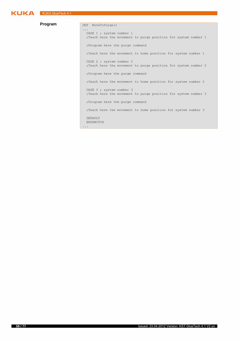
58 / 77
KUKA.GlueTech 4.1
Program DEF MoveToPurge()... CASE 1 ; system number 1 ;Teach here the movement to purge position for system number 1
;Program here the purge command
;Teach here the movement to home position for system number 1
CASE 2 ; system number 2 ;Teach here the movement to purge position for system number 2
;Program here the purge command
;Teach here the movement to home position for system number 2
CASE 3 ; system number 3 ;Teach here the movement to purge position for system number 3
;Program here the purge command
;Teach here the movement to home position for system number 3
DEFAULT ENDSWITCH...
Issued: 23.04.2012 Version: KST GlueTech 4.1 V2 en

8 Example programs
8 Example programs
8.1 Example program for dispensing
Program
Description
1 DEF GLUEING()2 INI3 Initialize And Start System 1 Fill Doser=Yes Set Program No=2 Param No=1 BeadData=14 Check Purge System 1 Time=10 min System 2 Time=10 min System 3 Time=10 min5 PTP HOME Vel= 100 % DEFAULT6 PTP P1 CONT Vel=100 % PDAT1 Tool[1] Base[0]7 Set High Motion Parameter=ON Path=10 % Orientation=25 %8 LIN P3 CONT Vel=0.5 m/s CPDAT2 Tool[1] Base[0]9 LIN P4 CONT Vel=0.5 m/s CPDAT3 GlueOn Distance=-10 mm Gun=1 Check PrePressure=Yes Tool[1] Base[0]10 LIN P5 CONT Vel=0.5 m/s CPDAT4 Tool[1] Base[0]11 LIN P6 CONT Vel=0.5 m/s CPDAT5 Tool[1] Base[0]12 LIN P7 CONT Vel=0.5 m/s CPDAT6 Tool[1] Base[0]13 LIN P8 CONT Vel=0.5 m/s CPDAT7 GlueOff Distance=-5 mm End Measurement=Yes Change Doser=No Tool[1] Base[0]14 LIN P9 CONT Vel=0.5 m/s CPDAT8 Tool[1] Base[0]15 Set High Motion Parameter=OFF16 PTP P10 CONT Vel=100 % PDAT2 Tool[1] Base[0]17 Process Complete18 PTP HOME Vel= 100 % DEFAULT19 Error Check System=120 END
Line Description
3 Init system
(>>> 7.3.1 "Inline form “Init system”" Page 47)
4 Monitoring purge gun
(>>> 7.4.2 "Inline form “Monitoring purge gun”" Page 55)
7 Set motion parameter
(>>> 7.3.3 "Inline form “Set motion parameter”" Page 49)
9 LIN with Open nozzle
(>>> 7.1.1 "Inline form “GLUE ON LIN”" Page 29)
13 LIN with Close nozzle
(>>> 7.1.3 "Inline form “GLUE OFF LIN”" Page 31)
15 Reset motion parameter
(>>> 7.3.3 "Inline form “Set motion parameter”" Page 49)
17 Terminate dispensing process
(>>> 7.3.4 "Inline form “Dispense complete”" Page 50)
19 Error check
(>>> 7.3.6 "Inline form “Error check”" Page 52)
59 / 77Issued: 23.04.2012 Version: KST GlueTech 4.1 V2 en

60 / 77
KUKA.GlueTech 4.1
8.2 Example program for dispensing with spline motion
Program
Description
1 DEF GlueingSpline()2 INI3 Initialize And Start System 1 Fill Doser=Yes Set Program No=2 Param No=1 BeadData=14 Check Purge System 1 Time=10 min System 2 Time=10 min System 3 Time 10=min5 PTP HOME Vel= 100 % DEFAULT6 PTP P1 Vel=100 % PDAT1 Tool[1] Base[0]7 SPLINE S1 Vel=0.5 m/s CPDAT1 Tool[1] Base[0]8 SPL P2 GlueOn Distance=-10 mm Gun=1 Check PrePressure=Yes9 SPL P310 SPL P411 SPL P512 SPL P6 GlueOff Distance=-5 mm End Measurement=Yes Change Doser=No13 PTP P7 Vel=100 % PDAT2 Tool[1] Base[0]14 PTP P8 CONT Vel=100 % PDAT3 Tool[1] Base[0]15 Process Complete16 PTP HOME Vel= 100 % DEFAULT17 Error Check System=118 END
Line Description
3 Init system
(>>> 7.3.1 "Inline form “Init system”" Page 47)
4 Monitoring purge gun
(>>> 7.4.2 "Inline form “Monitoring purge gun”" Page 55)
7 Spline block
8 SPL with Open nozzle
(>>> 7.1.1 "Inline form “GLUE ON LIN”" Page 29)
12 SPL with Close nozzle
(>>> 7.1.3 "Inline form “GLUE OFF LIN”" Page 31)
15 Terminate dispensing process
(>>> 7.3.4 "Inline form “Dispense complete”" Page 50)
17 Error check
(>>> 7.3.6 "Inline form “Error check”" Page 52)
Issued: 23.04.2012 Version: KST GlueTech 4.1 V2 en

9 System variables
9 System variables
9.1 I/O interface variables
Description The signals listed refer to the first dispensing controller. The first number in the signal names refers to the number of the dispensing controller (1, 2, 3). The signals of the second and third dispensing controllers are therefore not listed.
ao: analog output
ai: analog input
do: digital output
di: digital input
Signal name Meaning I/O
aoSL1MatFlow Setpoint for material $ANOUT[1]
aoSL1BeadShp Setpoint for air spray $ANOUT[2]
aoSLPrePressure Default value for pre-pressure
$ANOUT[3]
doSL1SystemOn System on $OUT[900]
doSL1EnablePump Enable pump $OUT[900]
doSL1EnableHeating Enable heating $OUT[900]
doSL1EnableHydraulic Enable hydraulic system $OUT[900]
doSL1EnableTimeHeating Enable heating timer $OUT[900]
doSL1AutoExternal Automatic external con-trol
$OUT[900]
doSL1HandExternal Manual external control $OUT[900]
doSL1FinishMeasure End application cycle $OUT[900]
doSL1FaultAckn Collective fault acknowl-edgement
$OUT[900]
doSL1SingleFaultAckn Individual fault acknowl-edgement
$OUT[900]
doSL1HeatingUnitReset Reset heating timer $OUT[900]
doSL1HydraulicReset Reset hydraulic timer $OUT[900]
doSL1PumpReset Reset pump timer $OUT[900]
doSL1CirculationReset Reset circulation timer $OUT[900]
doSL1WithoutMaterial Enable material flow $OUT[900]
doSL1StartSys Start application cycle $OUT[900]
doSL1Gun1On Open nozzle 1 $OUT[900]
doSL1PistSelect1 Open nozzle 2 $OUT[900]
doSL1PistSelect2 Open nozzle 3 $OUT[900]
doSL1PistSelect3 Open nozzle 4 $OUT[900]
doSL1ReloadMeter Fill dispenser $OUT[900]
doSL1CirculationOn Circulation on $OUT[900]
doSL1DoserChange Change dispenser $OUT[900]
doSL1AirOn Start swirl/E swirl $OUT[900]
doSL1Purge Purge $OUT[900]
doSL1PurgeA Purge component A $OUT[900]
doSL1PurgeB Purge component B $OUT[900]
doSL1PrePurge Pre-purge to pre-pres-sure acquisition
$OUT[900]
61 / 77Issued: 23.04.2012 Version: KST GlueTech 4.1 V2 en

62 / 77
KUKA.GlueTech 4.1
doSL1TriggerPrePressure Trigger to pre-pressure acquisition
$OUT[900]
doSL1PurgeEnable Enable purge $OUT[900]
doSL1EnableDocking Enable filling station $OUT[900]
doSL1EnableReference Enable reference run $OUT[900]
doSL1EnableMixerChange Enable mixer change $OUT[900]
doSL1OneComonentAppl Single-component opera-tion
$OUT[900]
doSL1SwirlLineMove E swirl characteristic run $OUT[900]
doSL1SwirlCoolingAir E swirl cooling air $OUT[900]
doSL1PressDischarge Depressurize $OUT[900]
doSL1ProgNo Program number bit 0 $OUT[900] TO $OUT[900]
doSL1ParamNo Parameter number set bit 0
$OUT[900] TO $OUT[900]
doSL1FaultToPLC Fault message to PLC $OUT[900]
doSL1ErrorNoToPLC Fault number to PLC bit 0 $OUT[900] TO $OUT[900]
doSL1ReturnValueToPLC Return value to PLC bit 0 $OUT[900] TO $OUT[900]
doSL1ReturnValueValid Valid return value to PLC $OUT[900]
diSL1PrePressOk Ready for application of material
$IN[1026]
diSL1Ready Enable external control $IN[1026]
diSL1DispOk Material application OK $IN[1026]
diSL1Doser1PrePressOk Dispenser 1 has reached pre-pressure
$IN[1026]
diSL1Doser2PrePressOk Dispenser 2 has reached pre-pressure
$IN[1026]
diSL1ToggleBit Toggle bit (system live) $IN[1026]
diSL1Doser1Full Dispenser 1 full $IN[1026]
diSL1Doser2Full Dispenser 2 full $IN[1026]
diSL1Doser1EmptyLimit Dispenser 1 has reached empty limit
$IN[1026]
diSL1Doser2EmptyLimit Dispenser 2 has reached empty limit
$IN[1026]
diSL1MeasurePassed Application cycle ended $IN[1026]
diSL1DoserSingleMode Dispenser in standalone mode
$IN[1026]
diSL1DoserChangeAckn Dispenser changed $IN[1026]
diSL1ReloadRequest Fill dispenser request $IN[1026]
diSL1PurgeRequest Purge request $IN[1026]
diSL1PrePurgeRequest Pre-pressure acquisition request
$IN[1026]
diSL1PumpIsON Pump ready $IN[1026]
diSL1HeatingStartPhase Heating in warm-up phase
$IN[1026]
diSL1HeatingIsOn Heating temperature reached
$IN[1026]
Signal name Meaning I/O
Issued: 23.04.2012 Version: KST GlueTech 4.1 V2 en

9 System variables
diSL1HeatingTimerActive Heating timer active $IN[1026]
diSL1HydraulicIsStartPhase Hydraulic system in start-up phase
$IN[1026]
diSL1HydraulicIsOn Hydraulic working pres-sure reached
$IN[1026]
diSL1MaterialEnabled Material flow enabled $IN[1026]
diSL1Barrel1RestAmount Barrel 1amount remaining < 10%
$IN[1026]
diSL1Barrel2RestAmount Barrel 2amount remaining < 10%
$IN[1026]
diSL1Barrel3RestAmount Barrel 3amount remaining < 10%
$IN[1026]
diSL1Barrel4RestAmount Barrel 4amount remaining < 10%
$IN[1026]
diSL1BarrelEmpty Barrel empty $IN[1026]
diSL1BarrelChangeActive Barrel change active $IN[1026]
diSL1ReferenceRequest Reference run request $IN[1026]
diSL1LeaveFillingStation Enable leave filling sta-tion
$IN[1026]
diSL1PurgeActive Purge active / 2-compo-nent purge
$IN[1026]
diSL1PurgeAActive Purge active, component A
$IN[1026]
diSL1PurgeBActive Purge active, component B
$IN[1026]
diSL1AInMixer Component 1 in mixer $IN[1026]
diSL1BInMixer Component 2 in mixer $IN[1026]
diSL1ABInMixer Components 1 and 2 in mixer
$IN[1026]
diSL1PurgePassed Purge ready $IN[1026]
diSL1Handshake Handshake $IN[1026]
diSL1OneComponentActive Single-component opera-tion active
$IN[1026]
diSL1MixerChangeRequest Mixer change request $IN[1026]
diSL1MixerChangeAckn Mixer change ended $IN[1026]
diSL1CirculationRequest Circulation request $IN[1026]
diSL1CirculationActive Circulation active $IN[1026]
diSL1SwirlReady E swirl motor ready $IN[1026]
diSL1SwirlSpeedOk E swirl speed OK $IN[1026]
diSL1MixtureUndefined Fault: two-component mixture undefined
$IN[1026]
diSL1FaultServo Servo fault $IN[1026]
diSL1FaultApplication Fault application $IN[1026]
diSL1FaultPump Pump fault $IN[1026]
diSL1FaultHeating Heating fault $IN[1026]
diSL1FaultHydraulic Hydraulic fault $IN[1026]
diSL1FaultFillingStation Filling station fault $IN[1026]
diSL1MatHigh Error material threshold high
$IN[1026]
Signal name Meaning I/O
63 / 77Issued: 23.04.2012 Version: KST GlueTech 4.1 V2 en

64 / 77
KUKA.GlueTech 4.1
diSL1MatLow Error material threshold low
$IN[1026]
diSL1MixtureHigh Error mixture above toler-ance
$IN[1026]
diSL1MixtureLow Error mixture below toler-ance
$IN[1026]
diSL1SystemNo System bit $IN[1026] TO $IN[1026]
diSL1DoserNo Dispenser no. $IN[1026]
diSL1Fault Fault that cannot be acknowledged
$IN[1026]
diSL1Warning Warning message $IN[1026]
diSL1AccumulationError Accumulation error $IN[1026]
diSL1ErrorNo Error bit $IN[1026] TO $IN[1026]
diSL1ProgReceived Program acknowledge-ment bit
$IN[1026] TO $IN[1026]
diSL1ParamReceived Parameter set acknowl-edgement bit
$IN[1026] TO $IN[1026]
diSL1MaterialReturnValue Material quantity return value
$IN[1026] TO $IN[1026]
diSL1DryByPLC With/without material under external control
$IN[1026]
diSL1PressDischargeReq Pressure discharge request
$IN[1026]
diSL1QuitByPLC Error handling (fault acknowledgement by PLC)
$IN[1026]
diSL1ReturnValueAckn Material return value acknowledgement
$IN[1026]
diSL1MeasurementActive Measurement cycle active
$IN[1026]
Signal name Meaning I/O
Issued: 23.04.2012 Version: KST GlueTech 4.1 V2 en
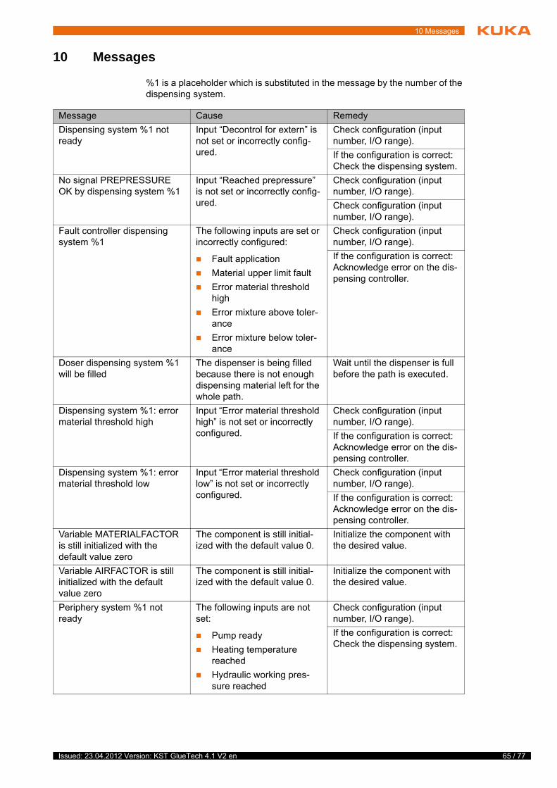
10 Messages
10 Messages
%1 is a placeholder which is substituted in the message by the number of the dispensing system.
Message Cause Remedy
Dispensing system %1 not ready
Input “Decontrol for extern” is not set or incorrectly config-ured.
Check configuration (input number, I/O range).
If the configuration is correct: Check the dispensing system.
No signal PREPRESSURE OK by dispensing system %1
Input “Reached prepressure” is not set or incorrectly config-ured.
Check configuration (input number, I/O range).
Check configuration (input number, I/O range).
Fault controller dispensing system %1
The following inputs are set or incorrectly configured:
Fault application
Material upper limit fault
Error material threshold high
Error mixture above toler-ance
Error mixture below toler-ance
Check configuration (input number, I/O range).
If the configuration is correct: Acknowledge error on the dis-pensing controller.
Doser dispensing system %1 will be filled
The dispenser is being filled because there is not enough dispensing material left for the whole path.
Wait until the dispenser is full before the path is executed.
Dispensing system %1: error material threshold high
Input “Error material threshold high” is not set or incorrectly configured.
Check configuration (input number, I/O range).
If the configuration is correct: Acknowledge error on the dis-pensing controller.
Dispensing system %1: error material threshold low
Input “Error material threshold low” is not set or incorrectly configured.
Check configuration (input number, I/O range).
If the configuration is correct: Acknowledge error on the dis-pensing controller.
Variable MATERIALFACTOR is still initialized with the default value zero
The component is still initial-ized with the default value 0.
Initialize the component with the desired value.
Variable AIRFACTOR is still initialized with the default value zero
The component is still initial-ized with the default value 0.
Initialize the component with the desired value.
Periphery system %1 not ready
The following inputs are not set:
Pump ready
Heating temperature reached
Hydraulic working pres-sure reached
Check configuration (input number, I/O range).
If the configuration is correct: Check the dispensing system.
65 / 77Issued: 23.04.2012 Version: KST GlueTech 4.1 V2 en

66 / 77
KUKA.GlueTech 4.1
Dispensing system %1: error mixture above tolerance
Input “Error mixture above tol-erance” is not set or incor-rectly configured.
Check configuration (input number, I/O range).
If the configuration is correct: Acknowledge error on the dis-pensing controller.
Dispensing system %1: error mixture below tolerance
Input “Error mixture below tol-erance” is not set or incor-rectly configured.
Check configuration (input number, I/O range).
If the configuration is correct: Acknowledge error on the dis-pensing controller.
Submit interpreter stopped or deselected
The submit interpreter is not active.
Start/select the submit inter-preter.
Group fault controller dispens-ing system %1
Input “Accumulation error” is set.
Check configuration (input number, I/O range).
If the configuration is correct: Acknowledge error on the dis-pensing controller.
Dispensing system %1: E-Swirl motor not ready or rota-tion speed not OK
Input “E-Swirl motor ready” is not set.
Check configuration (input number, I/O range).
If the configuration is correct: Check the dispensing system.
Where the gluing process should be continued?
The nozzle was closed during the application due to a fault.
Answer the dialog:
GlueOn: Continue on the next seam.
BCO: Continue on the same path as soon as the nozzle is back in position.
You have GlueOn selected. Gun will be opened at the beginning of the next seam
The message “Where the glu-ing process should be contin-ued” was answered with GlueOn.
-
You have BCO selected. Gun will be opened reaching BCO
The message “Where the glu-ing process should be contin-ued” was answered with SAK.
-
Message Cause Remedy
Issued: 23.04.2012 Version: KST GlueTech 4.1 V2 en

11 KUKA Service
11 KUKA Service
11.1 Requesting support
Introduction The KUKA Roboter GmbH documentation offers information on operation and provides assistance with troubleshooting. For further assistance, please con-tact your local KUKA subsidiary.
Information The following information is required for processing a support request:
Model and serial number of the robot
Model and serial number of the controller
Model and serial number of the linear unit (if applicable)
Model and serial number of the linear unit (if applicable)
Version of the KUKA System Software
Optional software or modifications
Archive of the software
For KUKA System Software V8: instead of a conventional archive, gener-ate the special data package for fault analysis (via KrcDiag).
Application used
Any external axes used
Description of the problem, duration and frequency of the fault
11.2 KUKA Customer Support
Availability KUKA Customer Support is available in many countries. Please do not hesi-tate to contact us if you have any questions.
Argentina Ruben Costantini S.A. (Agency)
Luis Angel Huergo 13 20
Parque Industrial
2400 San Francisco (CBA)
Argentina
Tel. +54 3564 421033
Fax +54 3564 428877
Australia Headland Machinery Pty. Ltd.
Victoria (Head Office & Showroom)
95 Highbury Road
Burwood
Victoria 31 25
Australia
Tel. +61 3 9244-3500
Fax +61 3 9244-3501
www.headland.com.au
67 / 77Issued: 23.04.2012 Version: KST GlueTech 4.1 V2 en
68 / 77
KUKA.GlueTech 4.1
Belgium KUKA Automatisering + Robots N.V.
Centrum Zuid 1031
3530 Houthalen
Belgium
Tel. +32 11 516160
Fax +32 11 526794
www.kuka.be
Brazil KUKA Roboter do Brasil Ltda.
Avenida Franz Liszt, 80
Parque Novo Mundo
Jd. Guançã
CEP 02151 900 São Paulo
SP Brazil
Tel. +55 11 69844900
Fax +55 11 62017883
Chile Robotec S.A. (Agency)
Santiago de Chile
Chile
Tel. +56 2 331-5951
Fax +56 2 331-5952
www.robotec.cl
China KUKA Automation Equipment (Shanghai) Co., Ltd.
Songjiang Industrial Zone
No. 388 Minshen Road
201612 Shanghai
China
Tel. +86 21 6787-1808
Fax +86 21 6787-1805
www.kuka.cn
Germany KUKA Roboter GmbH
Zugspitzstr. 140
86165 Augsburg
Germany
Tel. +49 821 797-4000
Fax +49 821 797-1616
www.kuka-roboter.de
Issued: 23.04.2012 Version: KST GlueTech 4.1 V2 en

11 KUKA Service
France KUKA Automatisme + Robotique SAS
Techvallée
6, Avenue du Parc
91140 Villebon S/Yvette
France
Tel. +33 1 6931660-0
Fax +33 1 6931660-1
www.kuka.fr
India KUKA Robotics India Pvt. Ltd.
Office Number-7, German Centre,
Level 12, Building No. - 9B
DLF Cyber City Phase III
122 002 Gurgaon
Haryana
India
Tel. +91 124 4635774
Fax +91 124 4635773
www.kuka.in
Italy KUKA Roboter Italia S.p.A.
Via Pavia 9/a - int.6
10098 Rivoli (TO)
Italy
Tel. +39 011 959-5013
Fax +39 011 959-5141
www.kuka.it
Japan KUKA Robotics Japan K.K.
Daiba Garden City Building 1F
2-3-5 Daiba, Minato-ku
Tokyo
135-0091
Japan
Tel. +81 3 6380-7311
Fax +81 3 6380-7312
Korea KUKA Robotics Korea Co. Ltd.
RIT Center 306, Gyeonggi Technopark
1271-11 Sa 3-dong, Sangnok-gu
Ansan City, Gyeonggi Do
426-901
Korea
Tel. +82 31 501-1451
Fax +82 31 501-1461
69 / 77Issued: 23.04.2012 Version: KST GlueTech 4.1 V2 en

70 / 77
KUKA.GlueTech 4.1
Malaysia KUKA Robot Automation Sdn Bhd
South East Asia Regional Office
No. 24, Jalan TPP 1/10
Taman Industri Puchong
47100 Puchong
Selangor
Malaysia
Tel. +60 3 8061-0613 or -0614
Fax +60 3 8061-7386
Mexico KUKA de Mexico S. de R.L. de C.V.
Rio San Joaquin #339, Local 5
Colonia Pensil Sur
C.P. 11490 Mexico D.F.
Mexico
Tel. +52 55 5203-8407
Fax +52 55 5203-8148
Norway KUKA Sveiseanlegg + Roboter
Sentrumsvegen 5
2867 Hov
Norway
Tel. +47 61 18 91 30
Fax +47 61 18 62 00
Austria KUKA Roboter Austria GmbH
Vertriebsbüro Österreich
Regensburger Strasse 9/1
4020 Linz
Austria
Tel. +43 732 784752
Fax +43 732 793880
www.kuka-roboter.at
Poland KUKA Roboter Austria GmbH
Spółka z ograniczoną odpowiedzialnością
Oddział w Polsce
Ul. Porcelanowa 10
40-246 Katowice
Poland
Tel. +48 327 30 32 13 or -14
Fax +48 327 30 32 26
Issued: 23.04.2012 Version: KST GlueTech 4.1 V2 en

11 KUKA Service
Portugal KUKA Sistemas de Automatización S.A.
Rua do Alto da Guerra n° 50
Armazém 04
2910 011 Setúbal
Portugal
Tel. +351 265 729780
Fax +351 265 729782
Russia OOO KUKA Robotics Rus
Webnaja ul. 8A
107143 Moskau
Russia
Tel. +7 495 781-31-20
Fax +7 495 781-31-19
kuka-robotics.ru
Sweden KUKA Svetsanläggningar + Robotar AB
A. Odhners gata 15
421 30 Västra Frölunda
Sweden
Tel. +46 31 7266-200
Fax +46 31 7266-201
Switzerland KUKA Roboter Schweiz AG
Industriestr. 9
5432 Neuenhof
Switzerland
Tel. +41 44 74490-90
Fax +41 44 74490-91
www.kuka-roboter.ch
Spain KUKA Robots IBÉRICA, S.A.
Pol. Industrial
Torrent de la Pastera
Carrer del Bages s/n
08800 Vilanova i la Geltrú (Barcelona)
Spain
Tel. +34 93 8142-353
Fax +34 93 8142-950
www.kuka-e.com
71 / 77Issued: 23.04.2012 Version: KST GlueTech 4.1 V2 en

72 / 77
KUKA.GlueTech 4.1
South Africa Jendamark Automation LTD (Agency)
76a York Road
North End
6000 Port Elizabeth
South Africa
Tel. +27 41 391 4700
Fax +27 41 373 3869
www.jendamark.co.za
Taiwan KUKA Robot Automation Taiwan Co., Ltd.
No. 249 Pujong Road
Jungli City, Taoyuan County 320
Taiwan, R. O. C.
Tel. +886 3 4331988
Fax +886 3 4331948
www.kuka.com.tw
Thailand KUKA Robot Automation (M)SdnBhd
Thailand Office
c/o Maccall System Co. Ltd.
49/9-10 Soi Kingkaew 30 Kingkaew Road
Tt. Rachatheva, A. Bangpli
Samutprakarn
10540 Thailand
Tel. +66 2 7502737
Fax +66 2 6612355
www.kuka-roboter.de
Czech Republic KUKA Roboter Austria GmbH
Organisation Tschechien und Slowakei
Sezemická 2757/2
193 00 Praha
Horní Počernice
Czech Republic
Tel. +420 22 62 12 27 2
Fax +420 22 62 12 27 0
Hungary KUKA Robotics Hungaria Kft.
Fö út 140
2335 Taksony
Hungary
Tel. +36 24 501609
Fax +36 24 477031
Issued: 23.04.2012 Version: KST GlueTech 4.1 V2 en

11 KUKA Service
USA KUKA Robotics Corp.
22500 Key Drive
Clinton Township
48036
Michigan
USA
Tel. +1 866 8735852
Fax +1 586 5692087
www.kukarobotics.com
UK KUKA Automation + Robotics
Hereward Rise
Halesowen
B62 8AN
UK
Tel. +44 121 585-0800
Fax +44 121 585-0900
73 / 77Issued: 23.04.2012 Version: KST GlueTech 4.1 V2 en

74 / 77
KUKA.GlueTech 4.1
Issued: 23.04.2012 Version: KST GlueTech 4.1 V2 en

Index
Index
Symbols$ACC_MA.CP 24$ACC_MA.ORI1 24$ACC_MA.ORI2 24$RED_ACC_CPC 24
AAdhesive bead application 7All configuration values, verifying/determining 26Analog voltage, proportional 8Application of 1-component / 2-component adhesives 7Areas of application 7
BBead shaping 7
CCalibrate_Equipment.src 24Calibration routine 6, 23Cell, configuring 17Communication 7Configuration 17Configuration, settings 18
DDelay times 8Delay times, air flow 24Delay times, manual configuration 21Delay times, material flow 23Dispensing instructions, overview 46Documentation, industrial robot 5
EExact positioning 6Example programs 59Extruded application 7
FFlatstream 7Functional principle 8Functions 7
HHandshaking 6
II/O interface variables 61Inline form GLUE OFF CIRC 34Inline form GLUE OFF LIN 31Inline form GLUE OFF PTP 36Inline form GLUE OFF SCIRC 45Inline form GLUE OFF SLIN 42Inline form GLUE OFF SPL 39Inline form GLUE ON CIRC 32Inline form GLUE ON LIN 29Inline form GLUE ON PTP 35Inline form GLUE ON SCIRC 43
Inline form GLUE ON SLIN 41Inline form GLUE ON SPL 37Inline form GLUE SWITCH CIRC 33Inline form GLUE SWITCH LIN 30Inline form GLUE SWITCH SCIRC 44Inline form GLUE SWITCH SLIN 41Inline form GLUE SWITCH SPL 38Inline form Init system 47Inline form Set program number 48Inline form, Dispense complete 50Inline form, Enable purge 56Inline form, Error check 52Inline form, Monitoring purge gun 55Inline form, Purge gun 54Inline form, Reload doser 51Inline form, Set motion parameter 49Inputs, configuration 20Installation 13Installation, GlueTech 13Introduction 5
KKnowledge, required 5KUKA Customer Support 67
MMachine data check 24Material / air flow determination 26Menus 15Messages 65Motion commands, overview 29Motion parameters 6MoveToPurge 57
OOperation 15Outputs, configuration 19Overview of GlueTech motion commands 29Overview of GlueTech Spline motion commands 37Overview, KUKA.GlueTech 7
PPath velocity, defining 25Product description 7Programming 29Purge instructions, overview 54Purge position 6Purge position, enable 56Purge position, teaching 57Purging 6
RReaction time after jump in analog output 26Reaction time, analog output 24
SSafety 11
75 / 77Issued: 23.04.2012 Version: KST GlueTech 4.1 V2 en

76 / 77
KUKA.GlueTech 4.1
Safety instructions 5Seam data set 6Seam data sets, configuration 22Seam number 6Service, KUKA Roboter 67Sound-insulating material 7Speed, proportional 8Spline motion commands, overview 37Status keys 15Support request 67Switching point 6Switching points 8Switching times 6Switching times of nozzle, determination 25Switching times, nozzle 23System requirements 13System variables 61
TTarget group 5TCP test 25TCP, testing 23Terms used 6Thin-jet 7Training 5
UUninstallation, GlueTech 13Update, GlueTech 13
WWarnings 5
Issued: 23.04.2012 Version: KST GlueTech 4.1 V2 en

77 / 77Issued: 23.04.2012 Version: KST GlueTech 4.1 V2 en
KUKA.GlueTech 4.1