labko frw direct flow regulation well
TRANSCRIPT

www.wavin-labko.fi
WAVIN-LABKO OY
Labkotie 1
FIN-36240 KANGASALA
Tel: +358 (0)20 1285 210
Fax: +358 (0)20 1285 280
E-mail: [email protected]
06/09
42AI03_e
Labko FRW Direct flow regulation well Installation, operation and maintenance instructions

Labko FRW Direct flow regulation well 42AI03_e
WAVIN-LABKO OY 2(10)
Contents
1 LABKO FRW DIRECT FLOW REGULATION WELL ................................................. 3
2 TECHNICAL DETAILS ............................................................................................... 3
2.1 OPERATION ...........................................................................................................................................3
2.2 CONSTRUCTION .....................................................................................................................................3
2.3 EUROHUK 800 MAINTENANCE SHAFT .....................................................................................................3
2.4 CAST IRON COVER AND FRAME ................................................................................................................3
3 INSTALLATION .......................................................................................................... 4
3.1 TRANSPORTATION AND HANDLING OF THE TANK .......................................................................................4
3.2 ANCHORING ...........................................................................................................................................5
3.2.1 FRW Direct NS3 – NS30 ..............................................................................................................5
Anchoring with sand .................................................................................................................................5
Anchoring to concrete slab .......................................................................................................................5
3.2.2 FRW Direct NS40 – NS150 ..........................................................................................................6
Anchoring to concrete slab .......................................................................................................................6
Anchoring with wooden logs .....................................................................................................................7
Anchoring with GRP-plates ......................................................................................................................7
3.3 FILLING THE MOUNTING PIT .....................................................................................................................8
3.4 INSTALLING MAINTENANCE SHAFT............................................................................................................8
4 MAINTENANCE .......................................................................................................... 9

Labko FRW Direct flow regulation well 42AI03_e
WAVIN-LABKO OY 3(10)
1 LABKO FRW DIRECT FLOW REGULATION WELL
Labko FRW Direct flow regulator is designed to be a part of the rain water treatment system on large, surfaced parking and storage areas, as well as industrial yards.
The flow regulation well limits sudden water flows by heavy rains to acceptable flow rate in separator systems and Q-bic infiltration systems.
The Flow regulator well shall not be installed as part of a sewage water treatment system.
2 TECHNICAL DETAILS
2.1 Operation
The Flow regulator well is equipped with a mechanical flow regulator, which maintains the nominal flow to the separator system. Although an instantaneous incoming flow may exceed the rated nominal value of the separator system.
2.2 Construction
NS3 – NS30 NS40 – NS150
Figure 1. Flow regulation well NS3 – NS150.
See more detailed information about construction of flow regulator wells www.wavin-labko.fi
2.3 EuroHUK 800 maintenance shaft
Flow regulation well includes EuroHUK 800 maintenance shaft, which is a watertight solution to be installed on top of the well. The flow regulator can be lifted out of the well through the maintenance shaft to be maintained if needed. Type of the maintenance shaft is chosen according to installation depth of the tank.
2.4 Cast iron cover and frame
The maintenance shaft can be equipped with cast iron cover and frame with a load carrying capacity of 40 tons.

Labko FRW Direct flow regulation well 42AI03_e
WAVIN-LABKO OY 4(10)
3 INSTALLATION
3.1 Transportation and handling of the tank
Handle the tank with care. The tank can’t be rolled or dropped. Fasten the tank properly for the transportation. Lift the tank with belts only from lifting eye bolts or circulate belts properly around the tank if forklift truck can’t be used. Avoid sudden moves when lifting the tank to ensure belts won’t slip. Inspect the well immediately after transporting it to the installation site for any damage that might have occurred during the transportation.
Figure 2. Transportation and handling instructions.

Labko FRW Direct flow regulation well 42AI03_e
WAVIN-LABKO OY 5(10)
3.2 Anchoring
Anchor the flow regulation well to prevent the buoyant force of the water in the ground moving the tank.
An anchoring slab should be cast, if
- The ground water level in the area is higher than the bottom of the well - The water transmission in the ground is weak and the rain water may
gather into the mounting pit of the separator
Start installation of the well by compacting a horizontally levelled 30 cm stone-free sand layer on the bottom of the pit.
3.2.1 FRW Direct NS3 – NS30
Anchoring with sand
The tank anchors to the ground by itself if installed right and the ground is pervious to water. In this case the separate anchoring isn’t needed. If separate anchoring isn’t performed, lift the tank on the sand layer and pour ca. 30 cm layer of water to the tank to stabilize it.
Anchoring to concrete slab
Cast 1500x1500x150 mm reinforced anchoring slab on the sand layer and 4 pcs min. Ø10 mm stainless steel lugs to slab.
Determinate the positions of the SS lugs before casting the concrete slab.
Lift the tank on the concrete slab and pour ca. 30 cm layer of water to the tank to stabilize it.
Anchor the tank by means of non-stretching 25 mm wide polyester belts with nominal capacity 2500 kg.
Anchor the tank with two belts. Slip belts behind lifting eye bolts around the collar of the sampling shaft in a way that both belts go around half a round. Fasten the heads of both belts to the lugs of the slab (Figure 3).
1. Concrete slab K30-2.
Steel reinforcement A500HW T8 #200
2. SS lugs T10 (4 pcs)
3. Non-stretching anchoring belts
Figure 3. Anchoring FRW Direct NS3 - NS30 to prevent buoyant force of the water in the ground.

Labko FRW Direct flow regulation well 42AI03_e
WAVIN-LABKO OY 6(10)
3.2.2 FRW Direct NS40 – NS150
Anchoring to concrete slab
A recommended way to anchor the tank is a reinforced concrete slab. Cast reinforced anchoring slab or place already casted concrete slab on the sand layer. Use e.g. concrete K30-2 and A500HW T8 #200 reinforcement for casting the slab. Cast the slab to square shape.
Cast stainless steel lugs to the concrete slab. See placement of lugs and size of the concrete slab from Figure 4. Anchor the tank by means of non-stretching 25 mm wide polyester belts with nominal capacity 2500 kg. Tie tightly 4 pcs ca. 4 m long belts to the upper lugs of the tank and 4 pcs ca. 2 m long belts to lower lugs. If you have ordered the anchoring belts from Wavin-Labko Oy, belts have been delivered as 4 pcs 6 m long belts which are measured and cut as mentioned above when installing the tank. NOTE! In any case the belts must be fixed to each anchoring lug of the spherical tank.
Compact a min. 20 cm stone-free sand layer on the anchoring slab.
Figure 4. Anchoring FRW Direct NS40 - NS150 to a concrete slab.
NS40 – NS50 NS65 NS80 – NS150
A 1400 1800 2600
B 1800 2200 3000
C 2200 2600 3400
1 Concrete slab K30-2. Reinforcement A500HW T8 #200
2 SS lugs T10 (8 pcs)
3 Non-stretching anchoring belts

Labko FRW Direct flow regulation well 42AI03_e
WAVIN-LABKO OY 7(10)
Anchoring with wooden logs
Alternatively, the anchoring can be performed with 4 pcs of impregnated wooden logs sized 100x100x2500-4000 mm depending on the size of the tank. Place the logs on both sides of the tank so that the logs are completely covered with sand. Add at least 200 mm layer of sand between the tank and the logs. Tie non-stretching belts around the logs so tight those won’t give in due to buoyant force. Anchor the tank by means of non-stretching 25 mm wide polyester belts with nominal capacity 2500 kg. Tie tightly 4 pcs ca. 4 m long belts to the upper lugs of the tank and 4 pcs ca. 2 m long belts to lower lugs. If you have ordered the anchoring belts from Wavin-Labko Oy, belts have been delivered as 4 pcs 6 m long belts which are measured and cut as mentioned above when installing the tank. NOTE! In any case the belts must be fixed to each anchoring lug of the spherical tank.
Figure 5. Anchoring FRW Direct NS40 - NS150 with impregnated wooden logs.
1 Impregnated wooden logs, 4 pcs (100x100x2500…4500 mm)
2 Non-stretching anchoring belts
Anchoring with GRP-plates
The tank can also be anchored with glass reinforced plastic plates (Figure 6). Place the plates to the same level with the tank’s bottom. Slip the anchoring belt through the holes of the plate and tie at least with double knot. The belts must be fixed to each anchoring lug of the tank and all of the plates must be used!

Labko FRW Direct flow regulation well 42AI03_e
WAVIN-LABKO OY 8(10)
Figure 6. Anchoring FRW Direct NS40 - NS150 with anchoring plates.
1 Anchoring plates, GRP, 8 pcs
2 Non-stretching anchoring belts
3.3 Filling the mounting pit
Compact the sand layers all around the tank with care. Use sieved gravel with grain size of 3…20 mm for filling the pit. Continue filling the pit until the ground level is reached.
Keep compacting the sand in 20 cm layers to the level of sewers. Install well’s inlet and outlet sewers. Keep filling the pit. Avoid using heavy vibration when compacting sand layers on top of the tank and on inlet and outlet sewers. Pour water to the tank while compacting sand.
3.4 Installing maintenance shaft
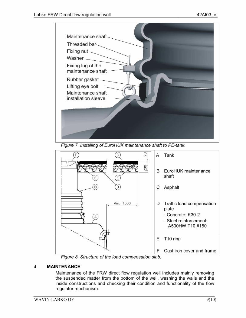
1. Remove the storage cover from the maintenance shaft installation sleeve. Place the rubber gasket to maintenance shaft’s lower edge. (Figure 7). Install the maintenance shaft vertically to installation sleeve. Lock the retaining latches.
2. Keep compacting the sand in 20 cm layers. Install ventilation pipes to maintenance shaft. Avoid using heavy vibration when compacting sand layers on top of the tank and on inlet and outlet sewers. Keep compacting until the ground level is reached. After filling the pit, cut the maintenance shaft to a proper height. Note that the cover and frame will give ca. 100-150 mm extra height for the maintenance shaft.
3. After cutting, install the frame of the cover. The frame must lean on the surrounding compacted layers of sand or a load compensation plate and the asphalt layer laid on the ground surface instead of leaning against the maintenance shaft.
4. In an area of heavy and medium weight traffic, a load compensation plate and a layer of asphalt must be laid to equalize the wheel loads (Figure 8).
5. Finally, fill the separator with water to the level of sewers.
Labko FRW Direct flow regulation well 42AI03_e
WAVIN-LABKO OY 9(10)
Figure 7. Installing of EuroHUK maintenance shaft to PE-tank.
A
Tank
B EuroHUK maintenance shaft
C Asphalt
D Traffic load compensation plate
- Concrete: K30-2
- Steel reinforcement: A500HW T10 #150
E T10 ring
F Cast iron cover and frame
Figure 8. Structure of the load compensation slab.
4 MAINTENANCE
Maintenance of the FRW direct flow regulation well includes mainly removing the suspended matter from the bottom of the well, washing the walls and the inside constructions and checking their condition and functionality of the flow regulator mechanism.
Labko FRW Direct flow regulation well 42AI03_e
WAVIN-LABKO OY 10(10)
Flow regulator mechanism should be maintained at least once a year in order to guarantee its proper functioning. Cleaning of the whole well is highly recommended to be done at the same time. Maintaining of the regulating mechanism includes following actions:
- Cleaning of the flow regulator mechanism from all suspended and solid matters gathered on it.
- Cleaning and lubricating the connection axle of the mechanism.
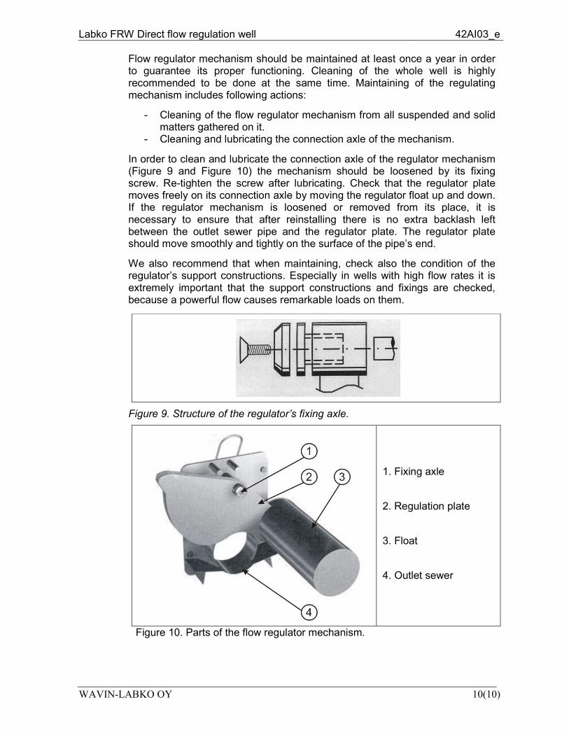
In order to clean and lubricate the connection axle of the regulator mechanism (Figure 9 and Figure 10) the mechanism should be loosened by its fixing screw. Re-tighten the screw after lubricating. Check that the regulator plate moves freely on its connection axle by moving the regulator float up and down. If the regulator mechanism is loosened or removed from its place, it is necessary to ensure that after reinstalling there is no extra backlash left between the outlet sewer pipe and the regulator plate. The regulator plate should move smoothly and tightly on the surface of the pipe’s end.
We also recommend that when maintaining, check also the condition of the regulator’s support constructions. Especially in wells with high flow rates it is extremely important that the support constructions and fixings are checked, because a powerful flow causes remarkable loads on them.
Figure 9. Structure of the regulator’s fixing axle.
1. Fixing axle
2. Regulation plate
3. Float
4. Outlet sewer
Figure 10. Parts of the flow regulator mechanism.