les pompes turbomoleculaires turbomoluecular pumps … · gb 02834 – ed 04 – march- 2007...
TRANSCRIPT

Rea
lizatio
n /
Pu
blic
atio
n :
Alc
ate
l Vacu
um
Tec
hn
olo
gy
Fran
ce -
Part
Nu
mb
er :
102710 –
Ed
11–
Marc
h 2
007
ATP SERIESLES POMPES TURBOMOLECULAIRES
TURBOMOLUECULAR PUMPS
Manuel de l’utilisateurUser’s manual

GB
0283
4 –
Ed 0
4 –
Mar
ch-
2007
Alcatel Vacuum Technology, as part of theAlcatel-Lucent Group, has been supplyingvacuum pumps, helium and hydrogen leakdetection systems, plasma sensors, vacuummeasurement for several years.Thanks to its complete range of products, thecompany has become an essential player inmultiple applications : instrumentation, Research& Developement, industry and semiconductors.
Alcatel Vacuum Technology has launched Adixen,its new brand name, in recognition of thecompany’s international standing in vacuumposition.With both ISO 9001 and 14001 certifications, theFrench company is an acknowlegded expert inservice and support, and Adixen products havethe highest quality and environmental standards.
With 45 years of experience, AVT today has aworldwide presence, through its international networkthat includes a whole host of experienced subsidiaries,distributors and agents.The first step was the founding of Alcatel VacuumProducts (Hingham- MA) in the United States, thirtyyears ago, reinforced today by 2 others USsubsidiaries in Fremont (CA) and Tempe (AZ).In Europe, AVTF-France headquarters and itssubsidiaries, Alcatel Hochvakuumtechnik (Germany),Alcatel Vacuum Technology UK (Scotland), AlcatelVacuum Technology Benelux (Netherlands), AlcatelVacuum Systems (Italy) and more recently AdixenSensistor AB in Sueden (in 2007) form the foundationfor the European partner network.In Asia, our presence started in 1993 with AlcatelVacuum Technology (Japan), and has beenstrengthened with Alcatel Vacuum Technology Korea(in 1995), Alcatel Vacuum Technology Taiwan (in2001), Alcatel Vacuum Technology Singapore, AlcatelVacuum Technology Shanghai (China) (in 2004) This organization is rounded off by more than 40represensatives based in a variety of continents.
Thus, whatever the circumstances, the users of Adixenproducts can always rely on quick support of ourspecialists in Vacuum Technology.

ATP Series Turbomolecular Pumps
1/1
GB
0039
3 - E
ditio
n 10
- M
arch
00
Welcome
Dear Customer,
You have just purchased anAlcatel turbomolecular pump.We would like to thank youand are proud to count youas one of our customers.
This product has benefitedfrom Alcatel's many yearsof experience in the field ofturbomolecular pump design.
In order to ensure the bestpossible performance ofthe equipment and yourcomplete satisfaction inusing it, we advise you toread this manual carefullybefore any interventionon your pump and to payparticular attention to theequipment installation andstart-up section.
APPLICATIONS:
• INDUSTRY
Cryogenics, Freeze drying, Vacuum drying, etc.
• INSTRUMENTATION
Mass spectrometry, surface analysis, etc.
• RESEARCH AND DEVELOPMENT
Ultra-high vacuum systems, Particle accelerators, etc.
• VARIOUS SEMICONDUCTOR PROCESSES
ADVANTAGES:
The reliable and sturdy design of ATP pumps ensures perfor-mance suited to the fields of application concerned.
MANUAL REFERENCE: 102 710EDITION: 11 - April 2007
Alcatel Vacuum Technology France - ATP User’s Manual

GB
0039
4 - E
ditio
n 10
- M
arch
00
ContentsATP User’s Manual
Introduction Introduction to the ATP range andits associated ACT controllers . . . . . . . . . . . A 10
Turbomolecular pump operating principle . . . . A 20
The differents versions . . . . . . . . . . . . . . . A 30
ACT controllers control modes . . . . . . . . . . . A 40
Accessories. . . . . . . . . . . . . . . . . . . . . . A 50
Integrable controllers . . . . . . . . . . . . . . . . A 60
Technical characteristics of pumps . . . . . . . . A 70
Dimensions of pumps . . . . . . . . . . . . . . . . A 80
Controller technical characteristics. . . . . . . . . A 90
Integrable controller technical characteristicstype Board and Brick. . . . . . . . . . . . . . . . A 100
Integrable controller technical characteristicstype OEM Board . . . . . . . . . . . . . . . . . . A 110
Alcatel Vacuum Technology France - ATP User’s Manual 1/4

GB
0039
4 - E
ditio
n 10
- M
arch
00
ContentsATP User’s Manual
Alcatel Vacuum Technology France- ATP User’s Manual2/4
Start-up Safety instructions . . . . . . . . . . . . . . . . . . B 10
Pump connections to an installation . . . . . . . . B 20
Mechanical connections. . . . . . . . . . . . . . . B 30
Water cooling connection . . . . . . . . . . . . . B 40
ACT 200 T and 600 T electrical connections. . B 50
ACT 200 T and 600 T «Remote Control»connector wiring . . . . . . . . . . . . . . . . . . . B 60
ACT 200 T and 600 T controller start-up . . . . B 70
ACT 1000 T electrical connections . . . . . . . . B 80
ACT 1000 T «Remote Control»connector wiring . . . . . . . . . . . . . . . . . . . B 90
ACT 1000 T controller start-up. . . . . . . . . . . B 100
RS 232 or RS 485 serial link wiring . . . . . . . B 110
Detailed description of RS commandsACT 200 T and 600 T . . . . . . . . . . . . . . B 120
Functions of integrable controllerstype Board and Brick . . . . . . . . . . . . . . . . B 130
Functions of integrable controllertype OEM Board . . . . . . . . . . . . . . . . . . B 140

GB
0039
4 - E
ditio
n 10
- M
arch
00
ContentsATP User’s Manual
Alcatel Vacuum Technology France - ATP User’s Manual 3/4
Operation First pump start-up / Safety instructions . . . . . . C 10
Turbomolecular pump operationin a pumping application. . . . . . . . . . . . . . C 20
Controlling the pump using the controllerfront panel . . . . . . . . . . . . . . . . . . . . . . C 30
Displaying the data concerning ACT 200 T and 600 T pumping . . . . . . . . . C 40
ACT 200 T and 600 T «Remote Control»connector «Ext. safety» contact operation . . . . . C 50
Controlling the pump usingcommunication software. . . . . . . . . . . . . . . C 61
Maintenance Diagnosis and troubleshootingACT 200 T and 600 T . . . . . . . . . . . . . . D 10
Diagnosis and troubleshooting ACT 1000 T . . . D 20
ATP 80/100/150/400Maintenance frequency . . . . . . . . . . . . . . . D 30
ATP 900 Maintenance frequency . . . . . . . . . D 40

GB
0039
4 - E
ditio
n 10
- M
arch
00
ContentsATP User’s Manual
Alcatel Vacuum Technology France- ATP User’s Manual4/4
Operation sheets Precautions before maintenance . . . . . . . . . . E 10
ATP 80/100 Pumps lubrication . . . . . . . . . . E 20
ATP 150/400/900 Pumps lubrication . . . . . . E 30
ATP 80/100 bearing replacement . . . . . . . . E 40*
ATP 150/400/900 bearing replacement . . . . E 50*
Cleaning parts . . . . . . . . . . . . . . . . . . . . E 60*
Pump running-in for ATP 80/100/150/400 . . E 70
Maintenance counters forACT 200 T and 600 T controllers . . . . . . . . E 80
ATP 900 pump running-in . . . . . . . . . . . . . . E 90
Maintenance counters forACT 1000 T controllers . . . . . . . . . . . . . . E 100
Appendix Pumping curves. . . . . . . . . . . . . . . . . . . . G 10
Maintenancecomponents
Maintenance parts . . . . . . . . . . . . . . . . . . F 10
* These chapters are included into the ball bearing replacement manual delivered withthe specific tool.

G 0
0396
- Ed
ition
09
- Feb
ruar
y 99
1/1
Chapter A
Alcatel Vacuum Technology France- ATP User’s Manual
ATP User’s Manual
Introduction
Introduction to the ATP range andits associated ACT controllers . . . . . . . . . . . . . . A 10
Turbomolecular pump operating principle . . . . . . A 20
The differents versions. . . . . . . . . . . . . . . . . . . A 30
ACT controllers control modes . . . . . . . . . . . . . A 40
Accessories . . . . . . . . . . . . . . . . . . . . . . . . . A 50
Integrable controllers . . . . . . . . . . . . . . . . . . . A 60
Technical characteristics of pumps . . . . . . . . . . . A 70
Dimensions of pumps . . . . . . . . . . . . . . . . . . . A 80
Controller technical characteristics . . . . . . . . . . . A 90
Integrable controller technical characteristicstype Board and Brick . . . . . . . . . . . . . . . . . . A 100
Integrable controller technical characteristicstype OEM Board . . . . . . . . . . . . . . . . . . . . . A 110

A 10Introduction to the ATP range andits associated ACT controllers
Alcatel Vacuum Technology France - ATP User’s Manual
GB
0039
7 - E
ditio
n 02
- Fe
brua
ry 9
9
1/2
- Ceramic ball bearings lubricated with grease; - Adjustable rotation speed between 6000 and 27000 rpm; - Natural convection, air or water cooling; - "C" version for corrosive application with nitrogen purge; - "HPC" high pressure version for semiconductor applications.
ATP turbomolecularpumps
ACT Controllers
Main characteristics
- Alphanumeric display; - Membran keyboard; - Monitoring of testing andtroubleshooting parameters; - Dry contact interface forstatus signals;
- Optocoupled control inputs; - RS 232/485 serial links; - Operation at all voltagesbetween 85 and 264 V,50/60 Hz.
The range of ACT controllers offers flexible use andinterfacing:
5 turbomolecular pump models from 80 to 900 l/s
3 controller models type ACT

A 10Introduction to the ATP range andits associated ACT controllers
Alcatel Vacuum Technology France - ATP User’s Manual
GB
0039
7 - E
ditio
n 02
- Fe
brua
ry 9
9
2/2
The different productsavailable
The pumps ATP 80 ATP 100 ATP 150 ATP 400 ATP 900ATP 80 C ATP 100 C ATP 150 C ATP 400 C ATP 900 C
Intake flange DN 63 ISO-K DN 100 ISO-K DN 100 ISO-K DN 160 ISO-K DN 200 ISO-K
DN 63 CF-F DN 100 CF-F DN 100 CF-F DN 160 CF-F DN 200 CF-F
natural convection x xCooling type air x x x x x
water x x x x x
The pumps ATP 400 HPC ATP 900 HPC
Intake flange DN 100 ISO-K DN 200 ISO-K
DN 160 ISO-K DN 200 CF-F
Water cooling x x
The controllers ACT 200 T ACT 600 T ACT 1000 T
Cable length 1 m / 1,5 m 1 m / 1,5 m 3.5 m / 5 m3.5 m / 5 m 3.5 m / 5 m 10 m10 m / 20 m 10 m / 15 m / 20 m
Electronic boards to beinserted in a rack x x
A 20
Alcatel Vacuum Technology France - ATP User’s Manual
GB
0039
8 - E
ditio
n 01
- M
arch
97
1/1
Turbomolecular pump operatingprinciple
Chamberto be
pumped
Secondarypumping
INLETPRESSURE
ATMOSPHERICPRESSURE
Primarypumping
Primary vacuumSecondary vacuum
Rotor
Stator
Dynamicseal
Motor
Exhaust
Inlet
The turbomolecular pump inan installation
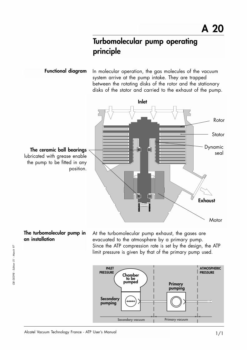
Functional diagram In molecular operation, the gas molecules of the vacuumsystem arrive at the pump intake. They are trappedbetween the rotating disks of the rotor and the stationarydisks of the stator and carried to the exhaust of the pump.
At the turbomolecular pump exhaust, the gases areevacuated to the atmosphere by a primary pump.Since the ATP compression rate is set by the design, the ATPlimit pressure is given by that of the primary pump used.
The ceramic ball bearingslubricated with grease enable
the pump to be fitted in anyposition.

A 30The different versions: Standard, "C" Corrosive, etc.
Alcatel Vacuum Technology France - ATP User’s Manual
GB
0039
9 - E
ditio
n 01
- A
pril
97
1/2
Standard VersionPumping of clean, non-
corrosive gases
As for the entire range, the pump rotation speed isadjustable, making it possible to produce the optimumpumping characteristics for the customer's application.There are two different types of speed: - the nominal speed which corresponds to the maximumrotation speed of the pump, or 27000 rpm; - the reduced speed, or STANDBY speed, adjustablebetween 6000 and 27000 rpm.
The inverted dynamic seal creates a high compression ratebetween the bearings and the pump exhaust and thusminimizes the quantity of corrosive gases in contact withthe bearings.
When used with a gas purge for high flow rateapplications, the dynamic seal can, on its own, provideexcellent protection for ultravacuum applications.
"C" VersionCorrosive applications
Inlet
Exhaust
N2 Purge
A 30The different versions:"HPC" High Pressure Corrosive
Alcatel Vacuum Technology France - ATP User’s Manual
GB
0039
9 - E
ditio
n 01
- A
pril
97
2/2
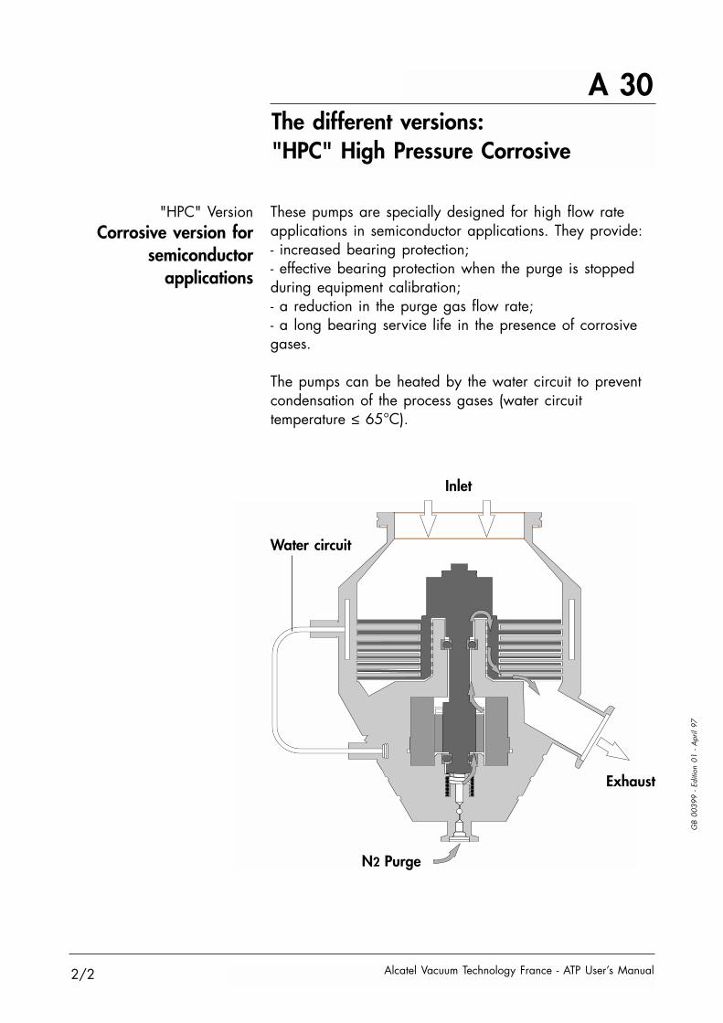
These pumps are specially designed for high flow rateapplications in semiconductor applications. They provide: - increased bearing protection; - effective bearing protection when the purge is stoppedduring equipment calibration; - a reduction in the purge gas flow rate; - a long bearing service life in the presence of corrosivegases.
The pumps can be heated by the water circuit to preventcondensation of the process gases (water circuittemperature ≤ 65°C).
"HPC" VersionCorrosive version for
semiconductorapplications
Inlet
Exhaust
Water circuit
N2 Purge

A 40ACT controllers control modes
Alcatel Vacuum Technology France - ATP User’s Manual
GB
0040
0 - E
ditio
n 02
- Fe
brua
ry 9
9
1/2
Local mode control
The front panel of the unitcomprises:
Remote controls
The remote control The remote control with theREMOTE CONTROL connectoris used:
- for the remote control ofthe START, STOP, STANDBYfunctions; - to replicate the monitoringparameters available in the form of dry contacts.
The RS232 serial link is used to control and monitorthe pump using a computer.
The RS485 serial link allows many pump installation ina network.
The wiring characteristics are given on B 110.
Parameter selection andconfiguration keys
Manual control keys
Parameter and messageLCD display
Pump status indicator lightsSTARTSTOP ENTER STAND BY
PREVIOUS
ACT 200 T
FAULT
0
1
RS 232 / 485TU
RBO PU
MP CA
BLE
REMO
TE CON
TROL
1
1
RS 232 serial link
RS 485 serial link
2
2
2

A 40ACT controllers control modes
Alcatel Vacuum Technology France - ATP User’s Manual
GB
0040
0 - E
ditio
n 02
- Fe
brua
ry 9
9
2/2
The ACT 600 T andACT 1000 T controllers are
1/2 rack units
START STOP STATUS STAND BY
ENTERPREVIOUS
ACT 600 T
FAULT

A 50
Alcatel Vacuum Technology France - ATP User’s Manual
Accessories
This filter protects the pump against solid particles.Mesh size 6 mm.
This filter stops particles ≥ 20 microns and is used in theevent of high densities of dust or risks of implosion whenpumping tubes or lamps.
Bake-out collar
Compact filter
Screen filter
Air refillelectrovalve system
This accelerates degassing and reduces the pressurelowering times.
This is used to refill the pump with air after stoppingpumping or for a power supply cut.
GB
0040
1 - E
ditio
n 02
- Fe
brua
ry 9
9
1/2
Pump accessories
ExhaustVenting valves DN 25 DN 40
Powered and controlled by the ACT 101923*Powered by the mains and
controlled by the ACT240V 50/60Hz 063177 063478220V 50/60Hz 056994 063191200V 50/60Hz 063176 063480115V 50/60Hz 063089 063099100V 50/60Hz 063175 063479
* ATP 900 only
Filter Inlet flangeP/N DN 63 DN 100 DN 160 DN 200
ISO-K 063000 056844 056942 063158CF-F 063115 056845 056928 063159
Filter Inlet flangeP/N DN 63 DN 100 DN 160 DN 200
ISO-K 063214 063215 063216 062911
P/NPump type
ATP 80 ATP 100 ATP 150 ATP 400 ATP 900200/240V
056934 056934 063028 101926 06332450/60Hz100/115V
063180 063180 063181 101927 06332350/60Hz

A 50Accessories
Alcatel Vacuum Technology France - ATP User’s Manual
GB
0040
1 - E
ditio
n 02
- Fe
brua
ry 9
9
2/2
Reduction flanges
Power supply cable Connection cable between the pump and the controller.
Cable lengthACT 200 T
P/N
1 m1.5 m3.5 m5 m10 m15 m20 m
105185A458759101956101957101958
-A458477
ACT 600 T
105086A458885101812101810101811105303
A458478
105086A458885101812101810101811
-A458478
ACT 1000 T
Flange DN 1 / DN 2 P/NS.S.**ALU*
Material
063268063269063270063267062900068912062901068911062902062904062905062906062903062725062907062909062908062910066659066660
63 ISO-K / 25 ISO-KF63 ISO-K / 40 ISO-KF63 ISO-K / 50 ISO-KF63 ISO-K / 63 CF-F100 ISO-K / 40 ISO-KF100 ISO-K / 40 ISO-KF100 ISO-K / 50 ISO-KF100 ISO-K / 50 ISO-KF100 ISO-K / 63 ISO-K160 ISO-K / 50 ISO-KF160 ISO--K / 63 ISO-K160 ISO-K / 100 ISO-K160 CF-F / 100 CF-F200 ISO-K / 63 ISO-K200 ISO-K / 100 ISO-K200 ISO-K / 100 ISO-K200 ISO-K / 160 ISO-K200 ISO-K / 160 ISO-K200 ISO-K / 250 ISO-K200 CF-F / 250 CF-F
* ALU: Aluminium ** S.S.: Stainless Steel

A 60
Alcatel Vacuum Technology France - ATP User’s Manual
GB
0040
2 - E
ditio
n 03
- M
arch
00
1/2
Integrable controllers
ACT 200 T BrickACT 200 T Board
Electronic boards can besubstitued to the box versionof the controllerACT 200 T when the pumphas to be integrated in acomplex installation orequipment.They provide the functions ofspeed variator, logic control(controlled by serial link ordry contacts) and powersupply (ACT 200 T Brick only) and all the necessarysecurities.The Board version must besupplied with DC.
ACT 200 T Board
ACT 200 T Brick
ACT 600 T BrickACT 600 T Board
Also, theses electronicboards can be substituedto the box version ofthe controller ACT 600 T.
ACT 600 T Board
ACT 600 T Brick
Connect the integrable controllers to the pump by orderingseparately the connection cable (see A 50 page 2).
ControllerACT 200 T
Part Number
BoardBrick
101933103517
ACT 600 T
102018103997

A 60
Alcatel Vacuum Technology France - ATP User’s Manual2/2
GB
0040
2 - E
ditio
n 03
- M
arch
00
Integrable controllers
OEM Board The integrable controller“OEM Board” (derivatedfrom CFV 100 formercontroller range) is a simplePC Board which can easilyintegrated in an installation.It can drive both ATP 80 andATP 100 pumps, in local orby remote control.
OEM Board: P/N. P0022E4
Power supply cableOEM Board / ATP 80-100
To connect the PC Board ,it is necessary to separatelyorder specific connectioncable.
Cable lenght P/N
0,5 m2,5 m3,5 m5 m10 m
A458755A458369A458425A458423A458424
Accessories Some accessoiries can be connected to the OEM Boardto extand some functions.
OEM Board accessories P/N
Time meter 5 VTime meter 10 VOutside light kitInterface kit
062761062320062939062969

A 70
Alcatel Vacuum Technology France - ATP User’s Manual
GB
0040
3 - E
ditio
n 03
- Fe
brua
ry 9
9
1/3
Technical characteristics of pumps
Model characteristics 80 100 150 400 900
Inlet flange DN 63 ISO-K 63 CF-F 100 ISO-K 100 CF-F 100 ISO-K 100 CF-F 160 ISO-K 160 CF-F 200 ISO-K 200 CF-F
N2 l/s 80 100 140 400 900Pumping speed He l/s 50 60 100 300 540
H2 l/s 40 40 80 250 300N2 8x10+7 8x10+7 7x10+8 7x10+8 1x10+9
Compression rate He 2500 2500 1.2x10+4 1.5x10+4 2x10+4
H2 300 300 1x10+3 1x10+3 2x10+3
Rotation speed rpm 27000Reduced speed rpm from 6000Sound level dBA ≤ 53Start-up time (0 to 27000) 1min45s 1min45s 2min 3min 3minExhaust flange ISO-KF DN 25 DN 25 DN 25 DN 40 DN 40
Standard version characteristics ATP 80 ATP 100 ATP 150 ATP 400 ATP 900
Limit pressure* measured acc.to Pneurop standard mbar 5x10⁻⁹ 5x10⁻⁹ 5x10⁻¹⁰ 8x10⁻¹⁰ 5x10⁻¹⁰
Maximum pressure at inlet in continuous operation** mbar 1x10⁻¹ 1x10⁻¹ 1x10⁻¹ 2x10⁻² 1x10⁻²
Maximum permissiblepressure at exhaust** mbar 2x10⁻¹ 3x10⁻¹ 4x10⁻¹ 2x10⁻¹ 3x10⁻¹
Maximum ambient temperature* °C 50Flange drying temperature °C 120 120 100 100 100
natural cooling kg 3 4.3 3 4.3Weight air cooling kg 4 5.3 4 5.3 6.5 9 17.5 18.5
water cooling kg 3.4 4.4 3.5 4.7 6.5 9 17 18Recommended primary pump Pascal 2005 Pascal 2005 Pascal 2005 Pascal 2015 Pascal 2021
* For a water-cooled pump with CF-F flange and exhaust pressure < 1.10-2 mbar.** The two maximum pressures cannot occur at the same time
Standard version

A 70
Alcatel Vacuum Technology France - ATP User’s Manual
GB
0040
3 - E
ditio
n 03
- Fe
brua
ry 9
9
2/3
Technical characteristics of pumps
Model characteristics 80 100 150 400 900
Inlet flange DN 63 ISO-K 63 CF-F 100 ISO-K 100 CF-F 100 ISO-K 100 CF-F 160 ISO-K 160 CF-F 200 ISO-K 200 CF-F
N2 l/s 80 100 140 400 900Pumping speed He l/s 50 60 100 300 540
H2 l/s 40 40 80 250 300N2 8x10+7 8x10+7 7x10+8 7x10+8 1x10+9
Compression rate He 2500 2500 1.2x10+4 1.5x10+4 2x10+4
H2 300 300 1x10+3 1x10+3 2x10+3
Rotation speed rpm 27000Reduced speed rpm from 6000Sound level dBA ≤ 53Start-up time (0 to 27000) 1min45s 1min45s 2min 3min 3minExhaust flange ISO-KF DN 25 DN 25 DN 25 DN 40 DN 40
Corrosive version «C»
Corrosives versions Characteristics ATP 80 C ATP 100 C ATP 150 C ATP 400 C ATP 900 C
Limit pressure* without purge meas.according to Pneurop standard mbar 5x10⁻⁹ 5x10⁻⁹ 5x10⁻¹⁰ 8x10⁻¹⁰ 5x10⁻¹⁰
Limit pressure* with purge meas.according to Pneurop standard mbar 5x10⁻⁸ 5x10⁻⁸ 1x10⁻⁷ 1x10⁻⁷ 1x10⁻⁷
N2 purge flow rate SCCM 50Maximum pressure at inlet in continuous operation** mbar 1x10⁻¹ 1x10⁻¹ 5x10⁻¹ 2x10⁻² 1x10⁻²
Maximum permissiblepressure at exhaust** mbar 2x10⁻¹ 3x10⁻¹ 4x10⁻¹ 2x10⁻¹ 1x10⁻¹
Maximum ambient temperature* °C 40 40 40 40 50Flange drying temperature °C 120 120 120 100 100N2 purge flange ISO-KF DN 16
Weight air cooling kg 4 5.3 4 5.3 6.5 9.1 17.7water cooling kg 3.4 4.4 3.5 4.7 6.5 9.2 17.2
Recommended primary pump 2005 C2 2005 C2 2021 C2 2033 C2 2063 C2
* For a water-cooled pump with CF-F flange and exhaust pressure < 1.10-2 mbar.** The two maximum pressures cannot occur at the same time

A 70
Alcatel Vacuum Technology France - ATP User’s Manual
GB
0040
3 - E
ditio
n 03
- Fe
brua
ry 9
9
3/3
Technical characteristics of pumps
«HPC» version HPC version characteristics ATP 400 HPC ATP 900 HPC
Inlet flange DN 100 ISO-K 160 ISO-K 200 ISO-K 200 CF-F
N2 l/s 325 380 700Pumping speed Ar l/s 365 430 785
SF6 l/s 365 430 785N2 7x10+6 1x10+7
Compression rate Ar 700 2x10+3
SF6 100 200Limit pressure without purge meas.according to Pneurop standard mbar 5x10⁻⁸ 5x10⁻⁸
Limit pressure with purge meas.according to Pneurop standard mbar 8x10⁻⁶ 5x10⁻⁵
N2 purge flow rate SCCM 50Maximum pressure at inlet in continuous operation* mbar 1x10⁻¹ 2x10⁻²
Maximum permissiblepressure at exhaust* mbar 6x10⁻¹ 4x10⁻²
Rotation speed rpm 27000Reduced speed rpm from 6000Start-up time (0 to 27000) 2 minMaximum ambient temperature °C 50Water circuit temperature °C ≤ 65Noise level dBA ≤ 53Weight kg 9 8.5 17.7Recommended primary pump 2063 C2 or ADP81Exhaust flange ISO-KF DN 40Purge flange ISO-KF DN 16Max N2 flux with 2063CP+ SCCM 340 400 450
* The two maximum pressures cannot occur at the same time

A 80Dimensions of pumps
ATP 80, ATP 100
Alcatel Vacuum Technology France - ATP User’s Manual
GB
0040
4 - E
ditio
n 03
- M
arch
00
1/6
65°
10
20
80,6
R
H
16
2011Ø 129,5
N equidistant
holes diam. 8,6
on diam. D
A°
95,4
Ø 12,1
13
119,
9
1,8
24,1
118
102
H
Ø 55,8
49,5
C
67,7
77,3
C
73,6
Ø 113
45,3
Ø F
Ø 113
12
R
26,2
Ø F
Inlet flange R H C F N D A°DN 63 ISO-K 130 151,5 102 95 - - -DN 63 CF-F 145 166,5 117 113,5 8 92,1 7,5°DN 100 ISO-K 103 124,5 75 130 - - -DN 100 CF-F 123 144,5 95 148,5 16 130,2 18,75°
DN 25ISO-KF
Water Inlet/Outlet(Any direction)
For tube diam. 4/6
Electrical connector
DN 25ISO-KF
N2 PURGEDN 16 ISO-KF
CF-FISO-K

A 80Dimensions of pumps
ATP 150
Alcatel Vacuum Technology France - ATP User’s Manual
GB
0040
4 - E
ditio
n 03
- M
arch
00
2/6
30°
86,6
Ø 149,7
60°
123
210,
7
28
Ø 132
49,8
87,4
85,4
91,5
Ø 12,1
26,2
18,7
5°
175,9
9712
2,1
16
116
35,5
13,4
103,
213
4
15,5
221,
7
Ø 132
Ø 148,5 Ø 130
12
17,2
20°
45°Grease
DN 25ISO-KF
N2 PURGEDN 16 ISO-KF
DN 25ISO-KF
DN 100 ISO-KDN 100 CF-F
Water Inlet/Outlet(Any direction)For tube diam.4/6
105
16 equidistant
holes diam. 8,6
on diam.130,2

A 80Dimensions of pumps
ATP 400
Alcatel Vacuum Technology France - ATP User’s Manual
GB
0040
4 - E
ditio
n 03
- M
arch
00
3/6
30°45°
20°
86,6
R
C
H
2660°
ø 189,5
106,1
H
C
E
A°
R
E
83
13,4
122,
1
15,5
81,3
97
175,9
91,5
Ø 12,126,2
17,2
Ø 189,5
Ø F
Ø F
Inlet flange R H C F E N T D A°DN 100 ISO-K 181,6 247,4 146,9 130 12 - - - -DN 100 CF-F 183,1 248,9 148,4 148,5 16 16 8,6 130,2 3,75°DN 160 ISO-K 151,1 216,9 116,4 180 12 - - - -DN 160 CF-F 168,1 233,9 133,4 198 16 20 8,6 181,1 6°ASA 6" 161,1 225,9 125,4 279,4 19 8 20,6 241,3 22,5°
DN 40ISO-KF
DN 40ISO-KF
Grease
ISO-K
CF-F - ASA
Water Inlet/Outlet(Any direction)For tube diam. 4/6
N equidistants
holes diam. T
on diam. D

A 80Dimensions of pumps
ATP 900
Alcatel Vacuum Technology France - ATP User’s Manual
GB
0040
4 - E
ditio
n 03
- M
arch
00
4/6
30°45°
20°
RH
C
EØ 240
60°
118,2
26
Ø F
235,1
134
A°
124,2
Ø 12,126,2
Ø F
E
C
R83
,681
,3
13,4
168
17,8
15,5
H
Ø 240
Inlet flange R H C F E N T D A°DN 200 ISO-K 145,8 211,5 118,5 240 12 - - - -DN 200 CF-F 165,8 231,5 138,5 253,2 20 24 8,6 231,9 7,5°ASA 6" 177,8 243,5 150,4 279,4 19 8 20,6 241,3 22,5°
DN 40ISO-KF
N2 PURGEDN 16 ISO-KF
DN 40ISO-KF
Grease
ISO-KCF-F - ASA
Water Inlet/Outlet(Any direction)For tube diam. 4/6
N equidistant
holes diam. T
on diam. D

A 80Dimensions of pumps
ATP 400 HPC
Alcatel Vacuum Technology France - ATP User’s Manual
GB
0040
4 - E
ditio
n 03
- M
arch
00
5/6
30°45°
20°
86,611
4,4
114,9
A°
90
11,5
85,1
Inlet flange R H C F E N T D A°DN 100 ISO-K 181,6 247,4 148,4 130 12 - - - -DN 100 CF-F 183,1 248,9 148,4 148,5 16 16 8,6 130,2 3,75°DN 160 ISO-K 151,1 216,9 116,4 180 12 - - - -DN 160 CF-F 168,1 233,9 133,4 198 16 20 8,6 181,1 6°ASA 6" 161,1 225,9 125,4 279,4 19 8 20,6 241,3 37,5°
DN 40ISO-KF
Grease
CF-F - ASA
60°
E
C
R
H15
,5
Ø 189,5
Ø F
106,1
DN 40ISO-KF
ISO-K
81,3
Water Inlet/Outlet(Any direction)For tube diam. 4/6
N equidistantholes diam. Ton diam. D

A 80Dimensions of pumps
ATP 900 HPC
Alcatel Vacuum Technology France - ATP User’s Manual
GB
0040
4 - E
ditio
n 03
- M
arch
00
6/6
30°45°
20°
60°
150,1
A°
70,8
11,5
76
C
R
H
E8,
5
Ø 260Ø 240
Ø F
118,2
15,5
81,3
86,6 14
9,6
Inlet flange R H C F E N T D A°DN 200 ISO-K 145,8 211,5 118,5 240 12 - - - -DN 200 CF-F 165,8 231,5 138,5 253,2 20 24 8,6 231,9 7,5°ASA 6" 177,8 243,5 150,4 279,4 19 8 20,6 241,3 22,5°
DN 40ISO-KF
N2 PURGEDN 16 ISO-KF
N2 PURGEDN 16 ISO-KF
DN 40ISO-KF
Grease
ISO-KCF-F - ASA
Water Inlet/Outlet(Any direction)For tube diam. 4/6
N equidistant
holes diam. T
on diam. D

A 90
Alcatel Vacuum Technology France - ATP User’s Manual
GB
0040
5 - E
ditio
n 03
- Fe
brua
ry 9
9
1/2
Controller technical characteristics
217 3
112,
5
10791.4
Ø 3
122.
412
8.4
ACT 200T
PREVIOUS +
STAND BYENTER
FAULT
START
STOP
213
198.1
Ø3
242
122.
4
128.
4
ACT 600T
PREVIOUS ENTER+
STAND BYSTATUSSTOP
FAULT
START
112,
5
3
Electrical characteristicsACT 200T and ACT 600T
Dimensions ACT 200T
ACT 600T
Characteristics ACT 200T ACT 600T
Weight kg 2.6 4Dimensions HxLxP mm 128.4x107x220 128.4x213x245Nominal voltage 85-132 V et170-264V 48/63 HzMaximum current 5.8 A / 3 AMaximum power W 100 300Ambient operating temperature T ≤ 50°C
Customer mains circuit breaker rating 10 A

A 90Controller technical characteristics
Alcatel Vacuum Technology France - ATP User’s Manual
GB
0040
5 - E
ditio
n 03
- Fe
brua
ry 9
9
2/2
Electrical characteristicsACT 1000T
Dimensions ACT 1000T
Characteristics ACT 1000T
Weight kg 8.5Dimensions HxLxP mm 132.5x219x453Power supply 100-120 V 200-240 V 50/60 HzMaximum power W 800Ambient operating temperature T ≤ 50°C
Customer mains circuit breaker rating 16 A
112.
5
100
54.75
512
2.4
453408
109.5
M 4
219
132.
5
STARTSTART
PREVIOUSPREVIOUS
ACT 1000 TACT 1000 T
STATUSSTATUSSTOPSTOP
--
FAULTFAULT
STAND BYSTAND BY
++ ENTERENTER

A 100
Alcatel Vacuum Technology France - ATP User’s Manual
GB
0040
6 - E
ditio
n 04
- M
arch
00
1/4
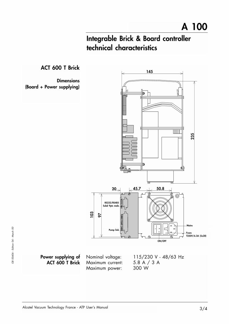
Integrable Brick & Board controllertechnical characteristics
ACT 200 T Brick
Dimensions(Board + Power supplying)
Nominal voltage: 115/230 V - 48/63 HzMaximum current: 5.8 A / 3 AMaximum power: 100 W
Power supplying ofACT 200 T Brick
8340.64
97103 TU
RBO PU
MP CA
BLERS232/485
Marche/Arrêt
Liaisonpompe
RS 232RS485
SUBD 9ptsmâle
Entrée secteur
FusiblesT250V/3.15A (5x20)
0
1
235
ON/OFF
FusesT250V/3.15A (5x20)
RS232RS485
Subd9pts male
Pumplink
Mains

A 100
Alcatel Vacuum Technology France - ATP User’s Manual
GB
0040
6 - E
ditio
n 04
- M
arch
00
2/4
1 2
15 16J4
J2
R15
S3
+ 72V0 V+ 15 V+ 5 V
0 V GND
Vn
Défaut Stand by
Démarrage Verte Connecteur
Entrées/Sorties
J5Paramétrageliaison série
Réglagevitesse
Connecteuralimentation
Trou de fixation Ø 3
Rouge Jaune
Jaune
J1
160.02
90.1
7
Integrable Brick & Board controllertechnical characteristics
Power supplying ofACT 200 T Board
ACT 200 T Board
Dimensions
Connector : type Molex Series 30-69 P.N. 09 - 91 -0700 equipped with 7 contacts P.N. 08 - 050 - 0106
DC voltage necessary to supply the board:+ 72 V / 1.4 A ± 1 V+ 15 V / 0.25 A ± 100 mV+ 5 V / 0.4 + 50 mV / - 100 mV
Functions of these integrable controllers (see B 130).
Pump at speedPump startingFaultStand by
GreenYellow
RedYellow
Power supplyconnector
Speedsetting
Serial linksetting
Input/Outputconnector
Holes diam 3
ACT 200 T BoardIt can be installed in an Europe size rack:Height: 100 mm - Depth: 180 mmOutside depth: 210 mm
A 100
Alcatel Vacuum Technology France - ATP User’s Manual
GB
0040
6 - E
ditio
n 04
- M
arch
00
3/4
1 0
97103 TU
RBO PU
MP CA
BLERS232/485
145
235
50.845.720
Liaison pompe
RS 232/RS485SUBD 9pts mâle
Marche/Arrêt
Entrée secteur
FusiblesT250/6.3A (5x20)
Integrable Brick & Board controllertechnical characteristics
ACT 600 T Brick
Dimensions(Board + Power supplying)
ON/OFF
FusesT250V/6.3A (5x20)
RS232/RS485Subd 9pts male
Pump link
Mains
Power supplying ofACT 600 T Brick
Nominal voltage: 115/230 V - 48/63 HzMaximum current: 5.8 A / 3 AMaximum power: 300 W

Alcatel Vacuum Technology France - ATP User’s Manual
GB
0040
6 - E
ditio
n 04
- M
arch
00
4/4
+ 72V 0 V+ 15 V+ 5 V
0 V GND
Vn
Défaut Stand by
Demarrage Verte
Rouge Jaune
Jaune
ConnecteurEntrées/Sorties
Trou de fixation Ø 3160.02
90.1
7
J1
J5 R 15S3J4
J10
Paramétrageliaison série
Réglagevitesse
Connecteuralimentation
A 100Integrable Brick & Board controllertechnical characteristics
Power supplying ofACT 600 T Board
ACT 600 T Board
Dimensions
Connector : type Molex Series 30-69 P.N. 09 - 91 -0700 equipped with 7 contacts P.N. 08 - 050 - 0106
Voltages delivered by the board:+ 72 V / 4 A ± 1 V+ 15 V / 0.25 A ± 100 mV+ 5 V / 0.4 A + 50 mV / - 100 mV
Functions of these integrable controllers (see B 130).
Pump at speedPump startingFaultStand by
GreenYellow
RedYellow
ACT 600 T BoardIt can be installed in an Europe size rack:Height: 100 mm - Depth: 180 mmOutside depth: 210 mm
Power supplyconnector
Speedsetting
Serial linksetting
Input/Outputconnector
Holes diam 3

A 110Integrable OEM Board controllertechnical characteristics
Alcatel Vacuum Technology France - ATP User’s Manual
GB
0040
7 - E
ditio
n 02
- M
arch
00
1/1
Power supplying ofOEM Board
OEM Board
A terminal plug with 7 pins, allows to supply the board 110 - 115 - 200 - 220 - 240 V AC, 50/60 Hz.
Secure the power line with an external time-delay fusedepending on the power supply:1 A for 100 / 115 V0.5 A for 200 / 220 / 240 V
Functions of these integrable controllers (see B 140).
Installed with M3 screws x 6, or in sliding rail(in Alcatel unit):Dimensions: 213 x 98 mm.
Encombrements
4 ST2
ST1
J2
321
+12V
J50V
0V
240VTerre220V
200V
115V
100V
J6J4+5V
12
J3
Holes diam Ø 3,2
Pumpcable
Powersupply
Power on
Fault
< 27000 tr/mn= 27000 tr/mn
START
STOP
213.286.3
92.7
20.3
97.5
86.3

GB
0040
8 - E
ditio
n 09
- Fe
brua
ry 9
9
1/1
Chapter B
Alcatel Vacuum Technology France- ATP User’s Manual
ATP User’s Manual
Start-up
Safety instructions . . . . . . . . . . . . . . . . . . . . . B 10
Pump connections to an installation . . . . . . . . . . B 20
Mechanical connections . . . . . . . . . . . . . . . . . B 30
Water cooling connection . . . . . . . . . . . . . . . . B 40
ACT 200 T and 600 T electrical connections . . . B 50
ACT 200 T and 600 T «Remote Control»connector wiring . . . . . . . . . . . . . . . . . . . . . . B 60
ACT 200 T and 600 T controller start-up . . . . . . B 70
ACT 1000 T electrical connections . . . . . . . . . . B 80
ACT 1000 T «Remote Control»connector wiring . . . . . . . . . . . . . . . . . . . . . . B 90
ACT 1000 T controller start-up . . . . . . . . . . . . . B 100
RS 232 or RS 485 serial link wiring . . . . . . . . . B 110
Detailed description of RS commandsACT 200 T and 600 T. . . . . . . . . . . . . . . . . . B 120
Functions of integrable controllerstype Board and Brick . . . . . . . . . . . . . . . . . . . B 130
Functions of integrable controllertype OEM Board . . . . . . . . . . . . . . . . . . . . . B 140

B 10Safety instructions
Alcatel Vacuum Technology France - ATP User’s Manual 1/3
GB
0040
9 - E
ditio
n 01
- M
arch
97
• Our equipment can be stored without specialprecautions (ambient temperature between 5 and 40° C)provided that the running-in procedure specified in themanual is observed for the first operation of the pump.
• The seal kits must be stored away from heat and light(direct sunlight and ultraviolet radiation) in order toprevent any hardening of the elastomers.
• Our products are designed to comply with current EECregulations. Any modification of the product made by the useris liable to lead to non-compliance with the regulations, oreven to put into doubt the EMC (electromagnetic compatibility)performance and the safety of the product. ALCATEL declinesany responsibility for such operations.
Unpacking
Storage
InstallationStart-up
To keep your product in the clean condition in which it leftour factory, we recommend to unpack the pump only onits assembly site.
It is advisable to keep the packaging.
Before switching on the pump, the user shouldstudy the manual and follow the safetyinstructions listed in the compliance certificatebooklet supplied with the pump.

B 10Safety instructions
Alcatel Vacuum Technology France - ATP User’s Manual2/3
GB
0040
9 - E
ditio
n 01
- M
arch
97
InstallationStart-up
(continued)
• Before any maintenance operations on a productperformed by a maintenance technician who has notreceived safety training (EMC, electrical safety, chemicalpollution, etc.), isolate the product from the various energysources (electricity, compressed air, etc.).
• The EMC performance of the product is obtained on thecondition that the installation complies with EMC rules.In particular, in disturbed environments, it is essential to: - use shielded cables and connections for interfaces,- stabilize the power supply line with meshing from the powersupply source to a distance of 3 m from the product inlet.
• The units containing control circuits are designed toguarantee normal safety conditions taking their normaloperating environment into account (use in rack). In specificcases of use on tables, make sure that no objects enter theventilation openings or block the openings when handling theunits.
• Certain controllers can be configured to start up automaticallyafter a power cut. In this case, it is the user's responsibility to take all theprecautions required to prevent the risks resulting from this typeof operation.
• When switching off an item of equipment containingloaded capacitors at over 60 VDC or 25 VAC, takeprecautions concerning the access to the connector pins(single-phase motors, equipment with mains filter, frequencyconverter, monitoring unit, etc.).
• When handling the equipment, use the devices providedfor this purpose (hoisting rings, handle, etc.).

GB
0040
9 - E
ditio
n 01
- M
arch
97
B 10Safety instructions
Alcatel Vacuum Technology France - ATP User’s Manual 3/3
InstallationStart-up
(continued)
• Risk of toppling over: although compliance with EECsafety regulations is guaranteed (normal range ± 10°), itis recommended to take precautions against the risk oftoppling over during handling, installation and operation.
• The performance and the operational safety of thisproduct are guaranteed provided that it is used in normaloperating conditions.
• The vacuum pump is also a compressor: incorrect usemay be dangerous.Study the user manual before starting up the pump.
• The access to the rotor of a turbomolecular pump withan unconnected intake is dangerous. Similarly, if the pumpis not switched on, it may be driven by another pump inoperation (risk of cuts).
• Make sure that the parts or chambers connected to theintake of our pumps withstand a negative pressure of1 bar in relation to the atmospheric pressure.
• The leaktightness of the products is guaranteed whenthey leave the factory for normal operating conditions. It isthe user's responsibility to maintain the level ofleaktightness particularly when pumping dangerous gases.

B 20Pump connections to an installation
Alcatel Vacuum Technology France - ATP User’s Manual 1/1
GB
0041
0 - E
ditio
n 01
- M
arch
97
The pump can operate inany position
The connection of the pumpto the installation must be
sufficiently rigid.
For this, reduce thefollowing as much aspossible: - dimensions a and b andthe flexibility of theconnection plate; - the overhang c betweenthe pump and its anchorpoint.
The equipment attachment devices should be sufficiently rigid to preventpotential risks in the event of failure of a rotary component or a violent shockon the pump (exceptional phenomena).
For this, use the rotary flange attachment holes. If the intake flange is attached with grips, use: - at least 3 grips for secondary pump ≤ 150 l/s;- at least 6 grips for secondary pump > 150 l/s.
The dimensions of the connection parts should be studiedcarefully:
c
ab
SpacerSupport plate
bellows rigid support
In.
In.
In.
In.
Some examples of unrecommended connection:

Connect the ventelectrovalve accessoryon the pump.Connect the pumpto primary pumpingcircuit*.
B 30Mechanical connections
Alcatel Vacuum Technology France - ATP User’s Manual 1/1
GB
0041
1 - E
ditio
n 01
- M
arch
97
Exhaust
Purgefor C and HPC models
A filtered dry nitrogensupply with the followingcharacteristics is required:- Dew point < 22°C- Dust < 1µm- Oil < 0.1ppm- Absolute pressure of 1to 1.3 bar.
Connect the nitrogen pipeto the DN16 purge fitting*.A built-in safety valvecontrols the pressure andguarantees a flow rate of50 SCCM.
Install the screen filter or compact filter accessory on thepump; connect the pump to the installation*.
Inlet
Ambient operatingtemperature
Air or natural convection cooled ATP: 0°C < T < 35°C; Water-cooled ATP: 0°C < T < 50°C.
* Different connection accessories can be found in the ALCATEL catalog.
Remove the protective parts blocking the intake, exhaust (and, if applicable,purge) openings; these components prevent foreign bodies from entering thepump during transport and storage.It is dangerous to leave them on the pump in operation.

B 40Water cooling connection
Alcatel Vacuum Technology France - ATP User’s Manual 1/1
GB
0041
2 - E
ditio
n 01
- M
arch
97
Water characteristics
Connection Connect the coolingcircuit with a rigidstainless steel or copperpipe (int. diam. 4 mm -ext. diam. 6 mm) (suppliedby customer).
The water flow rate is0.2 to 1 l/min for waterat 15°C at an ambienttemperature of 25°C.
It is recommended to use cooling water with the followingcharacteristics: - pH between 7.5 and 11- Hardness < 7 milli-équivalent/dm3
- Resistivity > 1500 Ω.cm- Solid pollution < 100 mg/dm3
- Max pressure = 7 bars- Temperature: 10 < T < 25°C (Std and C) and 0 < T ≤ 65°C (HPC).
B 50ACT 200 T and 600 Telectrical connections
Alcatel Vacuum Technology France - ATP User’s Manual 1/1
GB
0041
3 - E
ditio
n 02
- Fe
brua
ry 9
9
0
1
RS 232 / 485TU
RBO PU
MP CA
BLE
REMO
TE CON
TROL
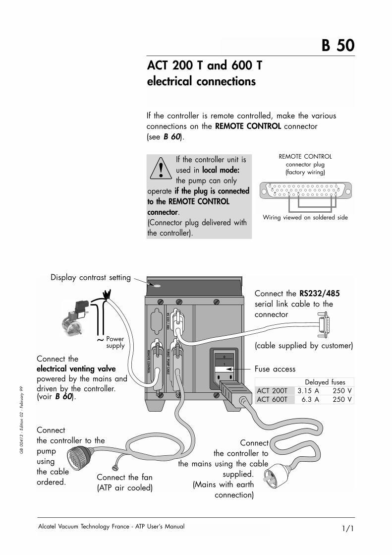
If the controller is remote controlled, make the variousconnections on the REMOTE CONTROL connector(see B 60).
If the controller unit isused in local mode:the pump can only
operate if the plug is connectedto the REMOTE CONTROLconnector.(Connector plug delivered withthe controller).
Connect the RS232/485serial link cable to theconnector
(cable supplied by customer)
Fuse access
15 1
30 16
44 41 39 31
REMOTE CONTROLconnector plug(factory wiring)
Wiring viewed on soldered side
Connectthe controller to thepumpusingthe cableordered.
Connectthe controller to
the mains using the cablesupplied.
(Mains with earthconnection)
Connect the fan(ATP air cooled)
Connect the electrical venting valvepowered by the mains anddriven by the controller.(voir B 60).
Powersupply
Delayed fusesACT 200T 3.15 A 250 VACT 600T 6.3 A 250 V
Display contrast setting

B 60ACT 200 T and 600 T "Remote Control" connector wiring
Alcatel Vacuum Technology France - ATP User’s Manual 1/2
GB
0041
4 - E
ditio
n 03
- Fe
brua
ry 9
9
When the units containing the control circuits are equipped with dry contactoutputs, it is the customer's responsibility to use the outputs in compliance withsafety regulations.
The control by voltage The inputs are considered to be activated if the AC or DC voltage applied is between 5 and 30 Volts:(DB 44 contacts, female connector)
Wiring suppliedby customer
Wiring suppliedby customer
15 1
30 16
44 38 34 3236 3137 35 3342 39
- + + +--+- ~= ~= ~= ~=5 to 30 V
15 1
30 16
44 383942 34 3236 31
0V
37 35 33
These inputs can be controlled by external contacts usingthe following wiring :
Principle of the inputcontrolled by voltage
When a voltage is applied on these inputs,the pump is running (see terminal plug wiring).The wiring of an external contact allows to signalan external safety when the contact is opened(i.e. emergency stop).
When a voltage is applied on these inputs,the Remote is validated. The opening of anexternal wired contact allows Local mode (pumpcontrol using front panel keypad).
When a voltage is applied on these inputs,the pump rotates at reduced speed. The opening ofan external wired contact allows pump rotation atnominal speed.
When a voltage is applied on these inputs,the pump starts up and accelerates to reach itsnominal or reduced speed (depending on setparameters). The opening of an external wiredcontact allows pump stopping.
+
_Externalcontactswired bythecustomer
Sub D 44 PtsACT female con.
+ 15 V50 mA
0 V
42
41
40
39
Ext. Safety31 - 32
REMOTE Mode33 - 34
STANDBY Mode35 - 36
Start/Stop37 - 38

B 60ACT 200 T and 600 T "Remote Control" connector wiring
Alcatel Vacuum Technology France - ATP User’s Manual2/2
GB
0041
4 - E
ditio
n 03
- Fe
brua
ry 9
9
Signaling usingoutput contacts:
These are dry contacts (250VAC-1A), their function is toreplicate the data concerning the pump operating status.
When the output contact is closed, this indicates:
15 14 13 12 11 10 9 8 7 1
30 16
44 43 3142 41 40 39
OV(-) OV + 15 V Max 50 mA
10V(+)
44 - 43 Used to monitor the selected parameter in the “Set Analog output“ menu (see B 70).
A 0-10V analog output is used to monitor variations incertain pump parameters (speed, temperature, etc.)This data can be used to plot curves.
1 - 2 The pimp is in running-in mode.5 - 6 The pump is operating7 - 8 Copy of Start command.
This contact can be used to drivethe roughing pump (see C 50).
9 - 10 The standby mode is selected.11 - 12 No faults are signalled.13 - 14 The pump has reached its nominal speed.15 - 30 The venting valve fitted in the pump is closed
(accessory).

B 70ACT 200 T and ACT 600 Tcontroller start-up
Alcatel Vacuum Technology France - ATP User’s Manual 1/4
GB
0041
5 - E
ditio
n 02
- Fe
bura
ry 9
9
Enter the sub-menus bypressing
The controller performs aself-test and identifies thepumps to which it can beconnected.
The initialization time isapproximately 12 seconds.
Display initialization
Indicator light test:they are lit in succession.
The equipment is identified :the programs versions aredisplayed.
The pump operation time andthe speed are displayed.
ATP 80/100VV:1.10 VE:1.10
52H ORPMREADY TO START!
FAULT
Configure the parametersfor the application usingthe various menus
Parameter settingaccess
Selection
Validation
• used to access the parameter setting mode.• used to exit the various menus without validating the functions.
• used to move in the menus, orfrom one parameter to another.
• used to select or adjust the value of the selected parameter.
• used to validate the selection of a menu, parameter or value.
• used to exit the menus and return to the pump parameterdisplay (on ACT 600 T ).
The parameter setting keys
PREVIOUS
ENTER
STATUS
PREVIOUS Access theparameterprogramming.
Select a running-incycle;
Start the cycle.
Once the various electrical connections have been made, setthe main switch on the rear panel to "I".
Display the monitoredparameters.
List the faults and thealerts.
DISPLAY SETUPRUNNING IN

B 70ACT 200 T and ACT 600 Tcontroller start-up
Alcatel Vacuum Technology France - ATP User’s Manual2/4
GB
0041
5 - E
ditio
n 02
- Fe
bura
ry 9
9
Configuring the controller
DISPLAY SETUPSETUPRUNNING IN
Enter the access code
Configure the 0-10V output
Modify the STANDBY speed
Give the authorization to restartthe pump after a power cut
Activate or disactivate the buzzer
Select the temperaturemeasurement unit
Set the serial link parameters
Modify the time before startingup the pump
Modify the time before opening theventing valve
Modify the venting valve openingtime
Program the maximum operatingtime before regreasing thebearings
Ball bearings life time counter
Modify the access code
Enter the access code andvalidate
SPEED: 6.75V = 27000rpmI motor:
ATP 80/100: 2.5A / 10VATP 150/400: 5.1A / 10V
θ.PUMP: 0.1V per 1°Cθ.CONT: 0.1V per 1°C
6000 to 27000 rpm
YES or NO
ON or OFF
°C or °F
RS232/RS485/NETWORK(see sub-menus folio 3 & 4)0 to 240mn 59s
0 to 59mn 59s
0 to 59mn 59s
M=0 (1000 to 15000 h)M=1 (1000 to 30000 h)M=2 (1000 to 45000 h)(3 times the maintenance time)(see E 80)
0 to 50000 hours
0 to 65535
0
Speed
12000
NO
ON
°C
RS232
0mn 0s
0mn 1s
0mn 1s
M=0
5000h
0 h
0
ACCESS CODE
SET ANALOG-OUT
STANDBY SPEED
AUTO-STARTING
BUZZER
TEMPERATURE UNIT
SET SERIAL LINK
SET START DELAY
TIME TO VENTING
VENTING TIME
MAINTENANCE
TIME BEARING
NEW CODING
Fact
ory
confi
gura
tion
ENTER

B 70ACT 200 T and ACT 600 Tcontroller start-up
Alcatel Vacuum Technology France - ATP User’s Manual 3/4
GB
0041
5 - E
ditio
n 02
- Fe
bura
ry 9
9
Serial link setting
ENTER
Transimission speed . . . . . . Parity . . . . . . . . . . . . . . . . Data length . . . . . . . . . . . . Number of STOP bits . . . . . . Authorizes or does notauthorize the echo ofcharacters received on the linkData separatingcharacter . . . . . . . . . . . . . Number of controller in amultiple link . . . . . . . . . . . . Authorizes transmission at pre-setintervals on the serial link, if ON,Set the transmission interval
Parity . . . . . . . . . . . . . . . . Data length . . . . . . . . . . . . Number of STOP bits . . . . . . Data separatingcharacter. . . . . . . . . . . . . . Number of controller in amultiple link . . . . . . . . . . . .
None None Even Odd8 bits 7 or 81 bit 1 or 2
44 (comma) 0 to 255
0 0 to 255
SPEEDPARITYDATA-BITSSTOP-BITSECHO
SEPARATOR
ADDRESS
SET DATA LOGGER
PARITYDATA-BITSSTOP-BITSSEPARATOR
ADDRESS
RS 232 RS 485RS 485NETWORK
Return to Temperature menu folio 2
Return to Temperature menu folio 2
SET SERIAL LINK RS 232RS 232 RS 485NETWORK
Serial link selection
Default Setting valuesvalues
9600 bauds 1200 2400 4800 9600None None Even Odd8 bits 7 or 81 bit 1 or 2
ON ON or OFF
44 (comma) 0 to 255
0 0 to 255
OFF ON or OFF0mn1s 0 to 4mn59s
or 255 s

B 70ACT 200 T and ACT 600 Tcontroller start-up
Alcatel Vacuum Technology France - ATP User’s Manual4/4
GB
0041
5 - E
ditio
n 02
- Fe
bura
ry 9
9
Serial link setting(continued)
Number of controller in asequence in the case of themultiple link . . . . . . . . . . . .
0 0 to 255ADDRESS
RS 232 RS 485NETWORKNETWORK
Return to Temperature menu folio 2

B 80ACT 1000T electrical connections
Alcatel Vacuum Technology France - ATP User’s Manual 1/1
GB
0041
6 - E
ditio
n 01
- M
arch
97
0
1
RS 232 / 485
TURBO PUMP CABLE
DRY CONTACTSREMOTE CONTROL
Connect the RS232serial link cableto the connector
(cable supplied bycustomer).
Connect the venting valveaccessory(see B 90)
If the unit isremote controlled,
make the various connections on the
REMOTE CONTROLterminal block
(see B 90).
Connect the controller to the pumpusing the cable
(separatelyordered).
Connectthe controller to the mainsusing the cable supplied.(Mains with earthconnection)
Connect thefan (ATP air cooled).

B 90ACT 1000 T "Remote Control"connector wiring
Alcatel Vacuum Technology France - ATP User’s Manual 1/2
GB
0041
7 - E
ditio
n 01
- M
arch
97
0 -10 V analog output:
11 12 13 14 15 16 17 18 19 20
1 2
GND
3 4 5 6 7 8 9 10
+
+ -
-GND GND GND
The control contactsExt. safety
1 - 2
Start/Stop3 - 4
REMOTE mode5 - 6
STANDBY mode7 - 8
Analog output9 - 10
When the contact is closed, an external safetydevice is signalled: the motor is stopped and the controller generates a fault. This contact mustbe opened for the pump to operate.
When the contact is closed, the pump is startedup and accelerates to reach its nominal orreduced speed (depending on parameter settings).If the contact is open, the pump is no longer powered.
When the contact is closed, the remote control modeis selected.If the contact is open, the local mode is selected(control using the front panel keypad).
When the contact is closed, the reduced speedrotation mode is selected.
Used to monitor the selected parameter(see ANALOG OUT menus).
When the units containing the control circuits are equipped with dry contactoutputs, it is the customer's responsibility to use the outputs in compliance withsafety regulations.

B 90ACT 1000 T "Remote Control"connector wiring
Alcatel Vacuum Technology France - ATP User’s Manual2/2
GB
0041
7 - E
ditio
n 01
- M
arch
97
11 12 13 14 15 16 17 18 19 20
1 2
GND
3 4 5 6 7 8 9 10
+
+ -
-GND GND GND
Signaling using outputcontacts
These are dry contacts: (250VAC-1A) their function is tocopy the data concerning the pump operating status.
Shut-offvalve
11 - 12
Air inlet valve13 - 14
Speed 15 - 16
Fault 17 - 18
Start 19 - 20
The contact is opened when a functional faultappears or when the "STOP" control is activated.In the latter case, the pump is reset toatmospheric pressure.The contact can be used to control a secondaryshut-off valve in order to retain the pressure inthe chamber when the pump is reset to atmosphericpressure.
Venting valve control and power supply (12V).
The contact is closed when the pump reaches the selected speed.
The contact is open if a fault appears and the motor is stopped.
The contact is closed when the "START" control isactivated.The contact can used to control a primary shut-offvalve.

B 100ACT 1000 T controller start-up
Alcatel Vacuum Technology France - ATP User’s Manual 1/4
GB
0041
8 - E
ditio
n 02
- Fe
brua
ry 9
8
Enter the sub-menusby pressing
The controller performs aself-test and identifies thepump to which it isconnected.
The initialization time isapproximately 4 seconds.
Display initialization
The equipment is identified,the program version isdisplayed.
Indicator light test:they are lit in succession.
The working screen isdisplayed.
ACT 1000 T V2.XX------------------------------
----------------CHECKING PROCEDURE
SEP/20/95 12:24:54ROT. SPEED 0 RPMΘ1 PUMP 21°C
FAULT
Configure the parametersfor the application usingthe various menus.
Parameter settingaccess
Selection
Validation
• used to access the parameter setting mode.• used to exit the various menus without validating the functions.
• used to move in the menus, orfrom one parameter to another.
• used to select or adjust the value of the selected parameter.
• used to validate the selection of a menu, parameter or value.
• used to exit the menus and return to the pump parameterdisplay
The parameter setting keys
PREVIOUS
ENTER
STATUS
PREVIOUS Accessthe parameterprogramming(see folio 2).
Once the various electrical connections have been made, setthe main switch on the rear panel to "I".
Display and/or selectthe parameters to bemonitored (see folio 4).
DISPLAY PARAMETERS

B 100ACT 1000 T controller start-up
Alcatel Vacuum Technology France - ATP User’s Manual2/4
GB
0041
8 - E
ditio
n 02
- Fe
brua
ry 9
8
Programmingthe parameters
* At power-up, the storage mode disappears automatically.
PARAMETERS
Modify the date
Modify the STANDBY speed
Modify the time before startingup the pump
Modify the maximum bearingoperating time
Modify the RS232 serial link
Configure the 0-10V output
Return to the factoryconfiguration (Alcatel reserved)
Modify the time beforeopening the air inlet valve
Modify the air inlet valveopening time
Change to storage mode(the timer is blocked).
6000 to 27000 tr/mn
0 to 59mn 59s
M=0 (5000 to 15000 h)M=1 (5000 to 30000 h)M=2 (5000 to 45000 h)(see details folio 3)
θ.PUMP 0.1V per 1°C6,75V = 27000 tr/mnθ.CONV 0.1V per 1°CCurrent 10V for 15000mA
0 to 59mn 59s
0 to 59mn 59S
ON / OFF
12000
0mn 0s
05000 h
Θ TEMP.
1s
1s
ON*
DATE
SPEED
START DELAY
BEARING MAINT
LIMIT
RS 232
AN.OUT Θ1 PUMP
SPEED
Θ CONVI.MOTOR
RESET CONTROLLER
BEARING
AIR INLET DELAY
OPEN
STOCK
Fact
ory
confi
gura
tion
ENTER
ENTER
ENTER
ENTER

B 100ACT 1000 T controller start-up
Alcatel Vacuum Technology France - ATP User’s Manual 3/4
GB
0041
8 - E
ditio
n 02
- Fe
brua
ry 9
8
Serial link setting
PREVIOUS
RS232
Transmission speed
Data lenght
Parity
Number of STOP bits
Number of controller ina multiple link
Authorizes or does notauthorize the echo ofcharacters received on the link
Data separatingcharacter
Authorizes transmission at pre-setintervals on the serial link
300 600 1200 2400 4800 9600
7 or 8
None Even Odd
1 or 2
00 to 999
ON or OFF
1 to127
ON or OFF
0 to 240mn 59 s
9600
8 bits
None
1 bit
0
ON
44(comma)
OFF
1s
SPEED
DATA
PARITY
STOP
ADDRESS
ECHO
SEPARATOR
DATA LOG START
DELAYFa
ctor
yC
onfig
urat
ion
ENTER
ENTER
Return to AN.OUT menu folio 2

B 100ACT 1000 T controller start-up
Alcatel Vacuum Technology France - ATP User’s Manual4/4
GB
0041
8 - E
ditio
n 02
- Fe
brua
ry 9
8
Configuring the displayscreen
DISPLAY
in revolutions/minute
in mA
of the pump (°C)of the controller (°C)
of the bearings (hours)of the controller (hours)
The date and time
The rotation speed
The motor current consumption
The temperature
The operating time
DATE
SPEED
CURRENT
TEMP Θ1 PUMPΘ CONV
SERVICE BEARINGSCONTROLLER
ENTER

B 110RS 232 or RS 485 serial link wiring
Alcatel Vacuum Technology France - ATP User’s Manual 1/1
GB
0041
9 - E
ditio
n 01
- M
arch
97
At the first power-up, the user finds the defaultconfiguration. The serial link parameters can be modifiedby accessing the corresponding unit menu.
The default configuration of the serial link is as follows: Type: RS 232 Transmission speed: 9600 baud Data length: 8 bits Parity: NONE Stop bit: 1
RS232/485 connectorwiring
1 2 3 4 5
GND (Ground)
V(+) (RS 485)
DTR (Data terminal ready)
TD (Transmission data)(Reception data) RD
(Data set ready) DSR
V(-) (RS 485)
6 7 8 9
Connection examples:
RS232 type serial linkwith a single controller
Multiple RS232 serial link:several units (up to 255)can be controlled on asingle link.
RS485 serial link connection:
DB 9 contacts, male connector.
STARTSTOP ENTER STAND BY
PREVIOUS
ACT 200 T
FAULT
See B 120 for the command and message reception syntax.
1
59
61
9
6
5
6
1
9
5
6
1
9
5
6
1
9
5
6
1
9
5
61
9
56
1
9
56
1
9
5
The multiple link is obtained by creating a loop:
Connect terminals 7 and 8 when the controller is at theend of the line.

1/10
B 120
Alcatel Vacuum Technology France - ATP User’s Manual
GB
0042
0 - E
ditio
n 03
- M
arch
00
Detailed description of RS commands
(valid from V1.10 version variable drives)
Conventions applicableto the syntax of all
commands:
Status values
Error messages
ADR
Syntax
Result
BRK
Syntax
Result
adr = address, from 000 to 255<CR> Carriage Return (ascii 13)<LF> Line Feed (ascii 10); between square brackets:
this character is not compulsory.
ok : command executed correctly
Err0 : adjustment error (out of bounds)Err1 : command error (syntax)Err2 : parameter error (e.g. non-hexadecimal character)Err3 : context errorErr4 : checksum error
Specifies the address of the device for networking.
#adrADRaaa<CR>[<LF>]adr = address of the device before the commandaaa = new address of the devicecondition : 000 ≤ aaa ≤ 255
#aaa,ok or Err2
This command is used to allocate a specific number to each of the products making up a network(loop for RS 232 or parallel for RS 485).
Note : it is important to note down the numberallocated to each device.
Stop the pump by braking (ATP 80/100 series only)
#adrBRK<CR>[<LF>]
#adr,ok
This command is used to brake the motor electrically, which isparticulary effective at high speed. It is currently only available forthe variable drive unit of the ACT 200T Board or ACT 200T cabinet.

2/10
B 120
Alcatel Vacuum Technology France - ATP User’s Manual
Detailed description of RS commands
GB
0042
0 - E
ditio
n 03
- M
arch
00
CYC
Syntax
Result
CKS
Syntax
Result
Enables or disables reply strings checksum
#adrCKSON<CR>[<LF>]Enables ascii character checksum at the end ofa reply string
or#adrCKSOFF<CR>[<LF>]
Disables ascii character checksum at the end ofa reply string
#adr,ok,S for CKSON#adr,ok for CKSOFF
This feature allows the user to test if there is any transmit errorwith a reply string.S is a character whose ascii value is the checksum, on 7 bits,of all the character ascii values from the beginning of the replystring to the character before S. The 8th bit of S (MSB, MostSignificant Bit) is always 1.
Starts the specified running-in cycle
#adrCYC1<CR>[<LF>] to start running-in program 1,or#adrCYC2<CR>[<LF>] to start running-in program 2
#adr,ok
Running-in program 1 should be executed after a pump maintenanceoperation (change of bearings).At the end of the program, the pump maintenance parameters areupdated and the «maintenance requested» alert can be cleared.Program 2 is used after regreasing (ATP series only), or afterprolonged storage (ATH 20/40 only).

3/10
B 120
Alcatel Vacuum Technology France - ATP User’s Manual
Detailed description of RS commands
GB
0042
0 - E
ditio
n 03
- M
arch
00
DLI
Syntax
Result
See also: DLR
DLR
Syntax
Result
See also: DLI, LNG, SEP, SHT
Defines the DataLogger transmission interval
#adrDLIxxx<CR>[<LF>]xxx: DataLogger send interval in secondscondition: 001 ≤ xxx ≤ 255
#adr,ok or Err2
Note: if ok, the interval sent is stored in user memory.
Enables DataLogger operation (only with RS232)
#adrDLR<CR>[<LF>]
#adr,sssss,nnnnn,iiii,ttttt,uuuu.o,www,ppp,vvv
Returns current values:sssss : current speed (in tr/mn)nnnnn : speed set point (in tr/mn)iiii : current (in mA)ttttt : pump working speed (in hours)uuuu.o : (reserved)www : pwm (reserved)ppp : pump temperature (°C)vvv : variator temperature (°C)
The main characteristics of the pump and its controller are sent over theRS link, at the rate defined by the DLI command.
Note: any new characters arriving on the serial port(RS 232) will cancel the automatic DataLogger transmission.

4/10
B 120
Alcatel Vacuum Technology France - ATP User’s Manual
Detailed description of RS commands
GB
0042
0 - E
ditio
n 03
- M
arch
00
HDR
Syntax
Result
IDN
Syntax
Result
Identifies the device which is communicating, and itssoftware version
#adrIDN<CR>[<LF>]
#adr, VS.... - Vx.zz’or#adr, VS.... - Vx.zz for Alcatel pump type»
Returns the type of Variable drive Supervisor, the software version (x),the software edition (zz), and the type of pump for which thisvariable drive is set up.
Defines the start character for a command reply string
#adrHDRnnn<CR>[<LF>]nnn: 3-digit decimal value of the ascii code ofthe corresponding character (with leading zeros). condition : 020 ≤ nnn ≤ 255
?adr,ok ? is the desired character.#adr,ErrX if error
Allows the user to distinguish between the first character in a«command» string (for which # cannot be changed) and the firstcharacter of a «reply» string.Affects the first character of ALL replies.Default value: the hash sign, # (ascii code = 035)If ok, the selected value is automatically stored in user memory.
ECH
Syntax
Result
Enables or disables command echoing
#adrECHON<CR>[<LF>]enables all characters received to be echoed over the serial port(RS 232 only).or#adrECHOFF<CR>[<LF>]disables all characters received from being echoed over the serial port.
#adr,ok
Comments:- This command is disabled in RS 485 operation, the value OFFis required.- Using a loop-type RS 232 network requires «ECHON» operation.

5/10
B 120
Alcatel Vacuum Technology France - ATP User’s Manual
Detailed description of RS commands
GB
0042
0 - E
ditio
n 03
- M
arch
00
LEV
Syntax
Result
Syntax
Result
See also: LNG, SEP, SHT
Returns the state of the parameters defined by SET
#adrLEV<CR>[<LF>]
#adr,nnnnn,sssss,aaaa,hhhhh or#adr,nnnnn rpm,sssss rpm,aaaa mA,hhhhh hours
Returns the current values:nnnnn : speed set pointsssss : stand-by speed set pointaaaa : current set pointhhhhh : alert level for pump bearing maintenance
Complete cabinet only:#adrLEV10<CR>[<LF>]
#adr,nnnnn,sssss,hhhhh,g,ccccc,eeeee,ddddd,pppp,qqqq
Returns current values:nnnnn : nominal speed set point (in rpm)sssss : stand-by speed set point (in rpm)hhhhh : alert level for pump bearing maintenance (in hours)g : regreasing counterccccc : pump working time (in hours)eeeee : electronic working time (in hours)ddddd : start delay (max 14459 s, that is 240 mn 59 s)pppp : time to venting (max 3599 s, that is 59 mn 59 s)qqqq : venting time (max 3599 s, that is 59 mn 59 s)
Returns the strings sent with the identification sub-strings
#adrLNG<CR>[<LF>]
#adr,okCIT>
Allows the parameters returned by the DLR, LEV and SPD commandsto be identified with sub-strings.Also generates the «CIT>» prompt each time a <CR> character isreceived.
LNG
Syntax
Result
See also: SHT

6/10
B 120
Alcatel Vacuum Technology France - ATP User’s Manual
Detailed description of RS commands
GB
0042
0 - E
ditio
n 03
- M
arch
00
NSP
Syntax
Result
See also: RPM, SBY
Swithes the speed set point to the nominal speed value
#adrNSP<CR>[<LF>]
#adr,ok
The speed set point for the pump is set to its nominal value.This configuration is automatically saved in user memory.This mode of operation prevents the use of the «RPM» command.
Used to select possible user choices
#adrOPT1 n<CR>[<LF>]choice of parameters on the analog output:
n = 0 : real pump speedn = 1 : pump currentn = 2 : temperature of pump bodyn = 3 : temperature of internal electronics
#adrOPT2 n<CR>[<LF>]choice of temperature unit:
n = 0 : degrees Centigraden = 1 : degrees Fahrenheit
Complete cabinet only:#adrOPT10 n<CR>[<LF>]
auto-starting:n = 0 : yesn = 1 : no
#adrOPT11 n<CR>[<LF>]buzzer: n = 0 : without
n = 1 : with
#adr,ok
Comment: The choice of the temperature unit affectsthe results of the DLR and STA strings and the display(if cabinet fitted).
OPT
Syntax
Result
See also: SEL

7/10
B 120
Alcatel Vacuum Technology France - ATP User’s Manual
Detailed description of RS commands
GB
0042
0 - E
ditio
n 03
- M
arch
00
RPM
Syntax
Result
See also: NSP, SBY
Defines the speed set point in stand-by mode
#adrRPM nnnnn<CR>[<LF>] or #adrRPMnnnnn<CR>[<LF>]
#adr,ok or #adr,ErrX1, out of range; 2, parameters ; 3, context (not in Stand-by mode)
Comment: if ok, the new speed is automatically stored in user memory.
Saves the internal parameters in user’s memory
#adrSAV<CR>[<LF>]
#adr,ok
Saves the current context (except for running-in cycles).If this command is sent when the pump is being supplied,it can for example allow automatic re-start in the event ofa power cut.
Switches the speed set point to the stand-by value
#adrSBY<CR>[<LF>]
#adr,ok
Resets the stand-by speed to its last stored value, and allowsit to be modified if an «RPM» command is sent.This configuration is automatically stored in user memory.
SAV
Syntax
Result
SBY
Syntax
Result
See also: NSP, RPM

8/10
B 120
Alcatel Vacuum Technology France - ATP User’s Manual
Detailed description of RS commands
GB
0042
0 - E
ditio
n 03
- M
arch
00
Syntax
Result
SEL
Syntax
Result
Returns the state of the parameters defined by OPT
#adrSEL<CR>[<LF>]
#adr,a,ua : Returns choice of parameters on the analog output:
a = 0 : real pump speeda = 1 : pump currenta = 2 : temperature of pump bodya = 3 : temperature of internal electronics
u : Returns the choice of temperature unit:u = 0 : degrees Centigrade u = 1 : degrees Fahrenheit
Complete cabinet only#adrSEL10<CR>[<LF>]
#adr,a,u,s,ba : Returns choice of parameters on the analog output:
a = 0 : real pump speeda = 1 : pump currenta = 2 : temperature of pump bodya = 3 : temperature of internal electronics
u : Returns the choice of temperature unit:u = 0 : degrees Centigrade u = 1 : degrees Fahrenheit
s : Returns auto-starting choice:s = 0 : no s = 1 : yes
b : Returns buzzer choice:b = 0 : without b = 1 : with
Defines the character which separates the parametersin a reply
#adrSEPnnn<CR>[<LF>]nnn: 3-digit decimal value of the ascii code of the desiredcharacter (with leading zeros).condition : 000 ≤ nnn ≤ 255
#adr,ok or #adr,ErrX if error
Allows the user to select the character which separatesthe parameters returned by the DLR, STA and LEVcommands. Default value: comma «,» ascii code = 044If ok, the selected value is automatically stored in user memory.
SEP
Syntax
Result

9/10
B 120
Alcatel Vacuum Technology France - ATP User’s Manual
Detailed description of RS commands
GB
0042
0 - E
ditio
n 03
- M
arch
00
SET
Syntax
ResultSee also: LEV
SHT
Syntax
Result
See also: LNG
SPD
Syntax
ResultSee also: LNG, SHT
Defines the internal operating parameters
#adrSET1 hhhhh<CR>[<LF>] maintenance time#adrSET2 sssss<CR>[<LF>] maximum time for start-up
(future)
Complete cabinet only:#adrSET10 ccccc<CR>[<LF>] : pump working time
(in hours)#adrSET11 eeeee<CR>[<LF>] : electronic working time
(in hours)#adrSET12 g<CR>[<LF>] : regreasing counter
(0 to 2 max)#adrSET13 ddddd<CR>[<LF>] : start delay (max 14459s,
that is 240mn 59s)#adrSET14 pppp<CR>[<LF>] : time to venting (max 3599s,
that is 59mn 59s)#adrSET15 qqqq<CR>[<LF>] : venting time (max 3599s,
that is 59mn 59s)
#adr,ok or #adr,ErrX
Returns the transmitted string without the identificationsub-string
#adrSHT<CR>[<LF>]
#adr,ok
The strings sent following DLR, LEV and SPD commands will now besent without the parameter identificationsub-strings (e.g; without the units).
Returns the current speed
#adrSPD<CR>[<LF>]
#adr,nnnnn#adr,nnnnn rpm

10/10
B 120
Alcatel Vacuum Technology France - ATP User’s Manual
Detailed description of RS commands
GB
0042
0 - E
ditio
n 03
- M
arch
00
STA
Syntax
Result
TMP
Syntax
Result
Returns the status of the internal dynamic parameters
#adrSTA<CR>[<LF>]
#adr,xxxxxx,yyyyyy,zzzzzz,sssss,iiii,www,ppp,vvv,ttttt<CR><LF>
adr: address543210xxxxxx status bits: yyyyyy fault bits:5 - RS echo (1->off) 5 - variable drive temperature4 - String long (0) / short (1) 4 - motor temperature3 - On (1) / Off (0) 3 - excess current2 - reduced or nominal 2 - sensors or start-upspeed reached(1) 1 - external1 - standby (1) 0 - pump not connected0 - running-in (1)
zzzzzz alert bits: sssss current speed value in rpm5 - reserved (future use) iiii current value in mA4 - reserved (future use) www reserved (pwm value)3 - variable drive temperature ppp pump temperature value2 - motor temperature vvv variable drive temperature1 - start-up time exceeded (future) ttttt pump operating time value0 - operating time exceeded
Reminder : The «#» character at the start of thereply string can be set with the «HDR» command.
The «,» character which separates the parameters in thereply string can be modified with the «SEP» command.
Defines the operating state of the turbomolecular pump
#adrTMPON<CR>[<LF>] start pump rotation#adrTMPOFF<CR>[<LF>] stop pump
#adr,ok or #adr,Err3 if the pump is already in the staterequested (context error)

B 130Functions of integrable controllersBrick and Board type
Alcatel Vacuum Technology France - ATP User’s Manual 1/4
GB
0042
1 - E
ditio
n 03
- M
arch
00
Using the switch S3 :
Factory configuration :9600 Bauds, WITHOUTParity, 8 bits, 1 Stop bit,RS232.
Serial link RS 232/485
Setting
Operation
Rotation speed setting
Refer to the Commands details sheet (B 120).
The potentiometer R15 (See folio 4) has to be setto a position such as not to exceed the 1/5 of its
full excursion to allow the speed programming from theserial link.
J4 Serial port
1
23
4
5
6
7
8
9
GND
V(+) DTR
TD RD
DSR
V(-)
120 Ω (Internal)
8 7 6 5 4 3 2 1ON
1
2
3
4
5 GND
Screen
Connect 7 to 8if load impedancenecessary between A et B
B (or V-) A (or V+)
6
7
8
9
RS 485 Link
1
2
3
4
5 GND
RS 232 Link
Screen
TD (Terminal or computer) RD (Terminal or computer)
6
7
8
9
Switch ON OFFNumber of STOP bits 1 1 bit 2 bitsData length 2 7 bits 8 bitsParity (Valid if switch 4 is off) 3 ODD EVEN
4 SANS AVECType of link 8 RS 485 RS 232
Switch5 6
Transmission speed 9600 ON ON4800 OFF ON2400 ON OFF1200 OFF OFF
Warning Electronic boards have been designed to complywith the electrical safety and electromagnetic
compatibility rules but they cannot be the purpose ofa certification as soon as they are sold alone.It is the user responsibility to ensure the externals shieldswhich are necessary to be in compliance with ECM andelectrical safety rules

B 130Functions of integrable controllersBrick and Board type
Alcatel Vacuum Technology France - ATP User’s Manual2/4
GB
0042
1 - E
ditio
n 03
- M
arch
00
4
3
2
1Speed
Start
Fault
Stand-by
Green
Red
Yellow
Yellow
Inputs/Outputsconnector
This remote control allows to command START, STOP,STANDBY at distance, and the copy of the monitoringparameters .
The connection is done on a female connector3M He 10 P.N. 34-52-6000 (Not supplied).
Inputs/Outputs connector J5
Typical applications
16151413121110987654321Speed Dry contacts relay
Tension level resistor
LED diode or indicator
5 to 30 V
ONFault
Stand-by
Rese
rved
GNDExt. safety.
ModeStand-byON/OFF
Analogical output
Out
puts
Inpu
ts
Not used
Output contacts signalisation :
They are open collector type outputs (Imax 100mA; Vmax 30V) whose function is to copy the informationrelated to the pump status.
The light indicator is on when the corresponding output is valid (low level).
Nominal speed hasbeen reached by thepump.
The pump isstarting up.A fault occurs.
Standby mode isselected.
Flashing : The speed is higher thanthe one selected.Lit : The selected speed isreached.Lit : The speed is lower than theone selected.Lit : Faulty pump. (See folio 4)Flashing : Alert is signalled.Lit : Standby mode is selected.
Contact Description Light indicator statusLight

B 130
Command inputs The input is regarded as valid when the external contactwhich is connected is closed (Low level: ground connected)and not valid if the contact is open (High level).
One analog output
This output allows to monitor the evolution of some pumpparameters (Speed, température…).
The output parameter selection is done through the RS232 (See B120). The speed, the current, the temperaturesare available on this output ( Factory configuration«Speed»).
Contact Input status
High: There is an external safety. The LED Fault is lit on,the pump doesn't start.Low: Contact connected to ground, necessary for pump'sstarting.
High: "Status" mode selected.Low: "Impulse" mode selected.This mode is valid for the two following commands .
External safety 10
Mode 11
Stand-by 12
Start/Stop 13
Analog output 14
"Status" mode:High: Nominal rotationspeed mode .Low: Reduced rotationspeed mode selected.(stand-by)
"Impulse" mode:A temporary closing of thecontact allows to alternatethe reduced and nominalspeeds.
"Impulse" mode:A temporary closing of thecontact allows to alternatebetween Start and Stop ofthe pump.
Nominal speed
Std-by Std-by Nominalspeed
Stop
Start Start Stop
"Status" mode:High: The pump is nolonger powered.Low: The pump starts andaccelerates.
Functions of integrable controllersBrick and Board type
Alcatel Vacuum Technology France - ATP User’s Manual 3/4
GB
0042
1 - E
ditio
n 03
- M
arch
00

B 130Functions of integrable controllersBrick and Board type
Alcatel Vacuum Technology France - ATP User’s Manual4/4
GB
0042
1 - E
ditio
n 03
- M
arch
00
The alerts are indicated by:- The flashing of the red light indicator ;- The alternation of HIGH and LOW levels of the output«FAULT».
The faults are indicated by:- The lighting of the red light indicator ;- The switching to the Low level of output «FAULT».
They can be identified using the serial link(See B120, command STA).
Note: Alcatel can provide upon request, a communicationsoftware which allows pump control and monitoring using amicro-computer (see C 61).
Refer to Diagnosis and Troubleshooting of the manual.
Faults monitoring
The potentiometer R 15 allows to set the rotation speed aslong as its position is further than 1/5 of the fullexcursion.
From the maximum position (Fully clockwise screwed), the speed is defined:- by the orders comming from serial link during the 4 firstturns (counterclockwise unscrewing) ;- manually within the limits of stand-by speed range (See characteristics table), this after the 5th turn (Speed increases when unscrewing).
Rotation speed setting
Factory configuration: R15 is set for a serial linkconfiguration with a Standby speed of
12000 RPM.

B 140
Alcatel Vacuum Technology France - ATP User’s Manual
Functions of integrable controllerOEM Board type
1/3
GB
0042
2 - E
ditio
n 02
- M
arch
00
Power “ON” and pump “Start/Stop” functions are madeusing switches located on the PC Board.
The detection of the pump operation is materialized bythree indicator lights (green, yellow, red) which indicatethe pump status (light ON = 1; Light OFF = 0).
* Pump rotation speed in rpm.** During the pump or converter cooling, the cycles 2,3 (or 5) will be happened again periodically until the user remedies theoverheating.
Local mode operation
Detection of rotation
Warning Electronic boards have been designed to complywith the electrical safety and electromagnetic
compatibility rules but they cannot be the purpose ofa certification as soon as they are sold alone.It is the user responsability to ensure the externals shieldswhich are necessary to be in compliance with ECM andelectrical safety rules.
PowerON Fault
Red
StartRotationspeed Stop
OEM Board
Yellow Green
Pilot lightsAction on button Pumpmotor
powered
Pumprotationspeed*START STOP Yellow Green Red
NO 001 Before starting 0
YES < 2700012 Starting 0
YES = 2700003 Pump at nominal speed 0
NO 004 Incident**
Overheating dueto pump or converter
0
YES < 2700005 Overloading 0
NO 006 Pumping stop 1

B 140
Alcatel Vacuum Technology France - ATP User’s Manual
Functions of integrable controllerOEM Board type
2/3
GB
0042
2 - E
ditio
n 02
- M
arch
00
Depending on P2 power supply cable connector wiring,the pump Start/Stop and an external safety can be remotecontrolled.
J3 connector allows the copy ofthe pump status data (equivalentto light indicators green-red-yellow) (voir folio 1).
Remote control mode
J2+12V
0V
0V
240VTerre220V
200V
115V
100V
+5V
12
J3
Pumpcable
Description
Standard wiring.A4-A5 : output by contactON/OFF
Without remote controlouter safeties
Buttons command.The buttons of the front ofpanel are operational.
Pump Start/Stopremote control
(by impulse contacts)
Interrupter command.Closed contact:pump startsOpened contact:pump stops
Pump Start/Stopremote control
(by maintained contact)
Opened contact:pump stopsNo indication by the redLED.
Outer safety switch wiring
A4-A5 terminals allows toswitch 250 V - 1 A max.Outer control
P2 connector wiring*
1
B
A
32 4 5
1
B
A
32 4 5
STARTSTOP
1
B
A
32 4 5
1
B
A
32 4 5
1
B
A
32 4 5
250 V 1 A max.
* P2 soldering side view;B2 and A1 in black are female pins, others are male pins.

B 140
Alcatel Vacuum Technology France - ATP User’s Manual
Functions of integrable controllerOEM Board type
3/3
GB
0042
2 - E
ditio
n 02
- M
arch
00
The faults are indicated by red light indicator which signals:- controller temperature increasing;- pump temperature increasing;- incorrect connection between pump and PC Board.
When it is “ON”, the motor is not supplied and the pumpdoesn’t run.
Fault monitoring

GB
0042
3 - E
ditio
n 09
- Fe
brua
ry 9
9
1/1
Chapter C
Alcatel Vacuum Technology France- ATP User’s Manual
ATP User’s Manual
Operation
First pump start-up /Safety instructions . . . . . . . . . . . . . . . . . . . . . C 10
Turbomolecular pump operationin a pumping application . . . . . . . . . . . . . . . . C 20
Controlling the pump using the controllerfront panel . . . . . . . . . . . . . . . . . . . . . . . . . . C 30
Displaying the data concerning ACT 200 T and 600 T pumping . . . . . . . . . . . C 40
ACT 200 T and 600 T «Remote Control»connector «Ext. safety» input operation . . . . . . . . C 50
Controlling the pump usingcommunication software . . . . . . . . . . . . . . . . . C 61

C 10First pump start-upSafety instructions
Alcatel Vacuum Technology France - ATP User’s Manual
GB
0042
4 - E
ditio
n 01
- M
arch
97
1/1
The pumps are designed so as not to present athermal risk for the user's safety. However, specific
operating conditions can generate temperatures whichrequire particular care to be taken by the user (externalsurfaces > 70°C).
Avoid moving or causing a shock on a pump inoperation.
There is a risk of seizing if the pump rotates in an axisperpendicular to its axis of rotation.
First pump start-up
Safety instructionfor use
When the pump is new, or after a prolonged shut-downof 3 months or more (under normal storage conditions),Alcatel recommend operating the pump at atmosphericpressure for 10 minutes (inlet and exhaust open toatmosphere) in order to ensure a slow rotation andgrease re-distribution in the pump ball-bearings.For this operation, inlet and pump exhaust are open toatmosphere.
The access to the rotor of a turbomolecular pumpwith an unconnected inlet is dangerous.

C 20
Alcatel Vacuum Technology France - ATP User’s Manual
GB
0042
5 - E
ditio
n 01
- M
arch
97
1/3
Turbomolecular pump operationin a pumping application
Example of a 1 valveassembly
Start-up: - start up ATP water cooling system; - open the E1 valve; - start up the primary pump (PPM); - start up the ATP, when the pressure in the chamberis ≤ 1 mbar.
Stop: - close E1;- stop the primary pump; - stop the ATP; - stop the cooling system.
ATP PPM
E1
Enceinte à vider
The chamber and pipes areat atmospheric pressure,
the pumps are switched off,the valves are closed
Chamber to beevacuated
When the pump is new, or after a prolonged shut-down of 3 months or more (under normal storageconditions), Alcatel recommend operating the pumpat atmospheric pressure for 10 minutes (inlet andexhaust open to atmosphere) in order to ensurea slow rotation and grease re-distribution in thepump ball-bearings.

C 20
Alcatel Vacuum Technology France - ATP User’s Manual
GB
0042
5 - E
ditio
n 01
- M
arch
97
2/3
Turbomolecular pump operationin a pumping application
Example of a 3 valveassembly
ATP
N2
PPM
E1E2E3
Enceinte à vider
The chamber and pipes areat atmospheric pressure,
the pumps are switched off,the valves are closed
Pre-evacuation of the chamber: - start up the PPM (primary pump); - start up the ATP water cooling system; - open the E2 valve.The pressure in the chamber ≤ 1mbar, the secondarypumping can be started up: - close E2; - open E1 and E3; - start up the nitrogen purge*; - start up the ATP.
The chamber is atatmospheric pressure,
the pumps are operating,the valves E2 and E3 are
closed, the purge and watercircuits are operating.
Pre-evacuation of the chamber: - close E1; - open E2.The pressure in the chamber is ≤ 1mbar: - close E2; - open E1; - open E3.
* N2 purge only for "C" and "HPC" models
Chamber to beevacuated

C 20
Alcatel Vacuum Technology France - ATP User’s Manual
GB
0042
5 - E
ditio
n 01
- M
arch
97
3/3
Turbomolecular pump operationin a pumping application
ATP Exhaust
Bake-out collar
Inlet flange
Dome
T < 120 °C
T < 200 °C
Dome
To reach the vacuumlimit quickly, the ATPcan be baked.In this case, thetemperature on thepump inlet flangemust be monitored:T < 120°C.
Bake-out collar (accessory)operation:
Refill the chamber with air Shut off the pumps by closing the E3 valve (E1 remainsopen) and open an air inlet on the chamber.
Stop pumping The pumps are shut off by closing the valves.- close the E3 valve; - with the ATP and PPM rotating, allow the N2 purge* toflow approximately 1 hour after pumping corrosivegases*; - Stop the ATP; - Close the E1 valve; - Stop the PPM. The ATP will be refilled with air if theaccessory is fitted and the relevant menus areprogrammed (see B 70 or B 100); - stop the water cooling circuit.

C 30Controlling the pumpusing the controller front panel
Alcatel Vacuum Technology France - ATP User’s Manual
GB
0042
6 - E
ditio
n 01
- M
arch
97
1/2
The pump is started up toreach the selected speed.
The orange rising speed indicator light comes on. Whenthe pump reaches its selected speed, the orange indicatorlight goes off and the green indicator light comes on.
The speed selection indicatorlight comes on. The pumpregulates its speed to reach the value of the programmedreduced speed (see B 70 or B 100).
The rotation speed monitoring indicator lights go off.The pump motor is no longer powered, the pumpdecelerates.
FAULT
FAULT
FAULT
Red litThe pump is faulty.This fault is accompaniedby an audible signal (if itis programmed).
Orange litThe pump rotation speed is lower than theselected speed.
Orange litStandby mode selectedOrange flashingRunning-in procedureactivated
Start-up the pump bypressing
Stop the pump bypressing
Select the reduced speedrotation mode by
pressing
Rotation indicator lights:
Green flashingThe pump rotation speedis higher than the selectedspeed (decrease of theselected speed duringoperation).Green litThe pump has reachedthe selected speed.
STANDBY
START
STOP

C 30Controlling the pumpusing the controller front panel
Alcatel Vacuum Technology France - ATP User’s Manual
GB
0042
6 - E
ditio
n 01
- M
arch
97
2/2
The valve is automatically controlled during a voluntarystoppage of the pump if a value other than zero has beenprogrammed in the "Venting Time" menu. During the entryof air, the pump can be started up but the valve will beclosed beforehand.In the event of a power cut, the valve is openedimmediately, without delay, even if it has beenprogrammed at a value other than zero.
It is possible to control the start-up of another pump beforethe start-up of the turbomolecular pump. Simply programa time other than zero in the "SET START DELAY" menu.When START is pressed, the backing pump is started upand the ATP is controlled after the delay.
Air inlet valveaccessory
Delayed start-up

C 40Displaying the data concerningACT 200 T and ACT 600 T pumping
Alcatel Vacuum Technology France - ATP User’s Manual
GB
0042
7 - E
ditio
n 02
- Fe
brua
ry 9
9
1/1
Successive display of last10 faults• number of hours ofoperation when the faultappeared• record number (1 to 10)• fault title
Successive display of last10 alerts• number of hours ofoperation when the alertappeared• record number (1 to 10)• alert title
Bearing data• operating time passed• maximum number of hoursauthorized before regreasingor replacing the bearings
Displaying the dataconcerning the pumping
400H FAULT 1D01:EXTERNAL SAFETY
420H WARNING 1W01:ATH MAINTENANCE
ENTER
ENTER
DISPLAYDISPLAY SETUPRUNNING IN
STATUS VER FAULTFAULTWARNING BEARINGS
STATUS VER FAULTWARNINGWARNING BEARINGS
STATUS VER FAULTWARNING BEARINGSBEARINGS
ENTER
ATP 20°C 1.50AACT 36°C 24000
STATUSSTATUS VER FAULTWARNING BEARINGS
ENTER
ENTER
ENTER
ENTER
ENTER
ENTERTime passed
ATP 80 / 100VV:1.10 VE:1.10
STATUS VERVER FAULTWARNING BEARINGS
Display of the equipmentand the program version
ENTER
ENTER
MAINTENANCE : 0450H/5000H
Pump and controller status• pump temperature• pump motor current• controller temperature• pump rotation speed

C 50ACT 200 T and ACT 600 T"Remote Control" connector "Ext. safety" input operation
Alcatel Vacuum Technology France - ATP User’s Manual
GB
0042
8 - E
ditio
n 02
- Fe
brua
ry 9
9
1/2
This input, which can be used to control an externalcontact safety device for the ACT controllers, is controlledin 2 different ways depending on the value given tothe SET START DELAY parameter accessible in theconfiguration menus.
15 1
30 16
44 38
8
34 3236 31
External safety
37
7
35 33
The external safety input is controlled continuously.If the “external safety” contact is open, it displays the fault"EXTERNAL SAFETY", lights up the red fault indicatorlight and inhibits the pump start-up. The output contact 7-8is kept open.
• Before pressing on "START",the external safety input is not controlled.
• After pressing on "START" and during a delay- of 4 seconds if SET START DELAY > 4 s- or between 1 and 4s if SET START DELAY ≤ 4 sthe external safety input is not controlled.
• After this delay, this input is handled by the ACT. If the “external safety” contact is open, it displays thefault "EXTERNAL SAFETY", lights up the red faultindicator light, opens the output contact 7-8 and inhibitsthe pump start-up.This contact can be used to control the roughing pump(see wiring example, following page).
If SET START DELAY = 0
If SET START DELAY ≠ 0
Note: In "REMOTE" mode, after an external fault, the pumpmust be set to the "STOP" status before starting up again.

C 50ACT 200 T and ACT 600 T"Remote Control" connector "Ext. safety" input operation
Alcatel Vacuum Technology France - ATP User’s Manual
GB
0042
8 - E
ditio
n 02
- Fe
brua
ry 9
9
2/2
Wiring example to control a roughing pump
31
39
8
7
41
32
Rem
ote
cont
rol
K1
K1
ACT
PPM
ATH
K1
RP

GB
0042
9 - E
ditio
n 01
- Fe
brua
ry 9
9
1/1
C 61Controlling the pumpusing communication software
Alcatel Vacuum Technology France - ATP User’s Manual
Connect the controllerto the micro-computer
(or terminal)
These instructions are validated for ACT 200/200T/600T,cabinet, Board and Brick version.
Realize the necessary connections (see B 110).
RS 232/485
0
1
RS 232 / 485TU
RBO PU
MP CA
BLE
REMO
TE CON
TROL
Communication software is compatible with Windows 3.11,95 et Windows NT (™ Microsoft).It require 2 Mo RAM. Communication ports 1 to 4 must beavailable.
This application is available on CDRom orFloppy disk 3”1/2.Consult us.
PC system requirements

1/1
GB
0043
0 - E
ditio
n 08
- Fe
brua
ry 9
8
Chapter D
Alcatel Vacuum Technology France- ATP User’s Manual
ATP User’s Manual
Maintenance
Diagnosis and troubleshootingACT 200 T and 600 T . . . . . . . . . . . . . . . . . D 10
Diagnosis and troubleshooting ACT 1000 T . . . . D 20
ATP 80/100/150/400Maintenance frequency. . . . . . . . . . . . . . . . . . D 30
ATP 900 Maintenance frequency . . . . . . . . . . . D 40

D 10Diagnosis and troubleshootingACT 200 T and ACT 600 T
Alcatel - High Vacuum Technology - ATP User’s Manual 1/3
GB
0043
1 - E
ditio
n 01
- M
arch
97
No event occurs afterpower on:
• No display;• Indicators does not
light.
Incoherent displayInoperative Keyboard(At starting or during
the pumping)
No light switches on
The pump isn’t running(pump seizing)No messages
• No mains current inthe unit.• Defective power cable.• Fuses.
Defective lights.
Cell seizing.
The controller is notpowered.
The display is differentfrom «Ready to start !»
The pump can be usedwithout indicators.
No message. Checkthe pump status.200T : Imax = 1.2 A600T : Imax = 0.8 ARotation speed : 0 rpmThe controller tempera-ture is increasing andthe warning «ACTTEMP» can appear(65°C)
• Change the power cable.• Check the fuses.• Call the ALCATEL CustomerService.
• Call the ALCATEL CustomerService.
• Call the ALCATEL CustomerService.
• Check the pump rotation(manually).• Make the pump maintenance.• Call the ALCATEL CustomerService.
INCIDENT CAUSE CONSEQUENCE REMEDY
The "FAULT" signal flashes;If the buzzer is selected "ON", it is activated;The controller doesn’t stop the pump.
The "FAULT" signal lights on;If the buzzer is selected "ON", it is activated;The controller stops the pump.
Default type:
"Warning" Wxx
"Fault" Dxx

D 10Diagnosis and troubleshootingACT 200 T and ACT 600 T
Alcatel - High Vacuum Technology - ATP User’s Manual
GB
0043
1 - E
ditio
n 01
- M
arch
97
2/3
WO1 : GREASING
WO2 :PUMP MAINTEN.
WO3 : ACT TEMP.
W04 :PUMP TEMP.
The authorized limit forball bearing maintenancetime has been reached.(M=0 or M=1)
Pump maintenance timewill be reached.
The controller temperatureis high between:- 60 and 70°C forACT 600 T; - 65 and 75°C forACT 200 T; but does not exceedthe authorized limit.
Pump temperature isbetween 75 and 85°C.
Bearing must bechanged.
• Regrease the pump andinitialize the maintenance counter(see E 80).
• Call the ALCATEL CustomerService.
• Check the controller coolingcircuit:- Internal fan for ACT 600T;- Ventilation for ACT 200T.
• Check the pump ventilation.
INCIDENT CAUSE CONSEQUENCE REMEDY

D 10Diagnosis and troubleshootingACT 200 T and ACT 600 T
Alcatel - High Vacuum Technology - ATP User’s Manual 3/3
GB
0043
1 - E
ditio
n 01
- M
arch
97
INCIDENT CAUSE CONSEQUENCE REMEDY
D01 : EXT SAFETY
D02 : DLY SOFTWARE
D03 : ACT TEMP.
D04 :PUMP TEMP.
D05 : HALL SENSORS
D06 :START FAULT
D07 : PUMP CURRENT
D08 : NO CONNECT
D09 :HIGH PRESS.
The external securitycontact on the REMOTECONTROL connector isactivated.
Soft counter default.
Controller temperatureexceeds the authorizedlimit 70°C for ACT 600Tor 75°C for ACT 200T
The pump motortemperature exceeds theauthorized limit 85°C.
Not used.
Not used.
Motor overcurrent orHall sensor default.
Pump not connected.
Not used.
The controller stops themotor. The pump can’trestart.
Starting current toohigh.
The pump can’t startup.
• Test the external safety devices(contact 31 - 32); • Repair the fault and pressSTART to restart (see B 60)
• Reinitialize the controller withthe main switch (0/1);• If the fault happens again, callthe ALCATEL Customer Service.
• Check that the cooling circuitis operating correctly:- Internal fan for ACT 600T;- Ventilation for ACT 200T.
• Check that the cooling circuitis operating correctly;• Reduce the working pressureor the flowrate.• If the fault happens again, callthe ALCATEL Customer Service.
• Reinitialize the controller withthe main switch (0/1);• If the fault happens again, callthe ALCATEL Customer Service.
• Check the cable connection.

D 20Diagnosis and troubleshootingACT 1000 T
Alcatel - High Vacuum Technology - ATP User’s Manual 1/4
GB
0043
2 - E
ditio
n 01
- M
arch
97
The "FAULT" indicator lights, the air inlet valve and/orthe "FAULT" contact on the "Remote Control" connectorare activated.
In the following table, we use the signs:Y Relay contact open;N Relay contact closed; "FAULT" indicator lit on; "FAULT" indicator lit off.
When a defectappears
Y
Y
Y
Y
N
N
N
Y
INCIDENT CAUSE CONSEQUENCE REMEDY
No event occursafter power on:
• No display;• Indicators doesnot light.
D00 :SEIZED PUMP
D01 :POWER
OVERHEAT
D03 :MOTOR
CONTROLOVERHEAT
D04 :HALL SENSOR
• No mains current inthe unit.• Defective powercable.• Fuses.
Cell seized.
Overheat signal by the«powered» sensor inthe unit.
Overheat signal by the«dimmer switch» sensorin the unit.
• Hall sensor default.• Motor out of order.• Pump no connected.
The controller is notpowered.
Check the pumpstatus: 0RPM.
The controller stopstemporarily the motor.Valves are notaffected.
The controller stopstemporarily the motor.Valves are notaffected.
The controller stopsthe motor.Valves are affectedand the pump can’trestart.
• Change the power cable.• Check the fuses.• Call the Alcatel CustomerService.
• Check the pump rotation(manually).• Make the pump maintenance.• Call the Alcatel CustomerService.
• Check the controller coolingcircuit (Air admissions and fan).• Call the Alcatel CustomerService.
• Check the controller coolingcircuit (Air admissions and fan).• Reduce the working pressureor the flowrate.• Call the Alcatel CustomerService.
• Check the cable connection.• Call the Alcatel CustomerService.
FAU
LT
17-1
813
-14
& 1
1-12

D 20Diagnosis and troubleshootingACT 1000 T
Alcatel - High Vacuum Technology - ATP User’s Manual
GB
0043
2 - E
ditio
n 01
- M
arch
97
2/4
Y
Y
Y
Y
N
N
Y
Y
Y
N
N
N
N
Y
D05 :OVERCURRENTOR SENSOR
D06 : EXT. SAFETY
D21 : PUMP OVERHEAT
D22 : CONTROLLEROVERHEAT
D23 :HOT PUMP
D24 : BEARINGS MUST
BE CHANGED
D26 :NO CONNECT
• Motor overcurrent orhall sensors default.• Motor out of order.Pump no connected.
The external securitycontact on the connec-tor is activated.
Pump overheat.
Overheat signal by the«management» sensorin the unit.T > 60°C.
Pump temperatureexceeds 75°C.
The bearing life timehas been reached.
• Temperature probefailure.• Pump no connected.• Sensor no connected.
The controller stopsthe motor.Valves are affectedand pump can’trestart.
The controller stopsthe motor.Valves are affectedand pump can’trestart.
The controller stopsthe motor.Valves are notaffected.
The controller stopsthe motor.Valves are notaffected.
Fault is displayed(message).
The «fault» signalflashes.
The controller stopsthe motor.Valves are notaffected.
• Check the cable connection.• Call the Alcatel CustomerService.
• Test the external safety devices(contact 1 - 2); • Repair the fault and pressSTART to restart.
• Check the pump cooling.• Reduce the working pressureor the flowrate.
• Check the controller coolingcircuit (Air admissions and fan).• Reduce the working pressureor the flowrate.• Call the Alcatel CustomerService.
• Check the pump cooling.• Reduce the pressure or theflow.• If the default is still present theD21 appears.
• Change the emergencybearings; • Call the Alcatel CustomerService.
• Check the cable controllerelectrical connection.• Call the Alcatel CustomerService.
INCIDENT CAUSE CONSEQUENCE REMEDYFAU
LT
17-1
813
-14
& 1
1-12

D 20Diagnosis and troubleshootingACT 1000 T
Alcatel - High Vacuum Technology - ATP User’s Manual 3/4
GB
0043
2 - E
ditio
n 01
- M
arch
97
N
N
N
N
N
N
N
Y
N
N
D27 :DATE AND TIME
D28 :DISABLE EEPROM
WRITE
D29 :INPUT POWER
D30 :EEPROM
CHECKSUM
D37 : GREASINGBEARING
• Converter memoryproblem.• STOCK Parameteractivated.
Writing memoryproblem on themanagement card.
• Mains power failure.• Problem on the 72Vpower supply.
Reading memoryproblem on themanagement card.
The bearing relubricatedtime has been reached.
The controller suppliespower to the pumpbut the display isincorrect.
The controller suppliespower to the pumpbut the data are notsaved.
The pump is notpowered and generatepower to the controller.The defect appearsbriefly before thepower cut.
The controller stopsthe motor.
The «fault» signalflashes.
• Access the DATE menu andupdate the new date.• Reinitialize the controller withthe main switch (0/1)• Call the Alcatel CustomerService.
• Reinitialize the controller withthe main switch (0/1)• Call the Alcatel CustomerService.• Contacter le Service Client.
• Check the cable connection tothe pump and controlle. • Check the fuses.• Call the Alcatel CustomerService.
• Call the Alcatel CustomerService.
• Make the relubrication andreinitialize the maintenancecounter.
INCIDENT CAUSE CONSEQUENCE REMEDYFAU
LT
17-1
813
-14
& 1
1-12

D 20Diagnosis and troubleshootingACT 1000 T
Alcatel - High Vacuum Technology - ATP User’s Manual
GB
0043
2 - E
ditio
n 01
- M
arch
97
4/4
INCIDENT CAUSE CONSEQUENCE REMEDY
When the controller isstarted up, the pumpcannot be identified.
Converter powersupply problem.
The microprocessor isrunning on itself: it isnot able to control theoperating sequency.
The micro board isnot working.
The controller is helpup.
The controller isblocked.
The controller is notworking.
Momentaneaously, thecontroller is notworking.
• Call the ALCATEL CustomerService.
• Call the ALCATEL CustomerService.
• Call the ALCATEL CustomerService.
• If the speed is zero when themessage appears, wait for themessage disappiars and tryagain the starting procedure.• If the speed is not zero, waitfor running stops and start againthe pump.• If the message continues, callthe ALCATEL Customer Service.
ACT 1000 T V2.X-------------
PUMP MEMORY FAULT
ACT 1000 T V2.X-------------
WDOG CONVERTER

GB
0043
3 - E
ditio
n 01
- M
arch
97
1/1
D 30
Alcatel - High Vacuum Technology - ATP User’s Manual
ATP 80, ATP 100, ATP 150, ATP 400Maintenance frequency
Pump curve:ATP 80 - ATP 80 C
ATP 100 - ATP 100 CATP 150 - ATP 150 CATP 400 - ATP 400 C
ATP 400 HPC
Use of the pump
Housing temperaturemeasuring point
Intervals for relubrication and the ball bearings replacementdepend on the type of process used.
16000
14000
12000
10000
8000
6000
4000
Relubrication schedule (hours)
200010 20 30 40 50
Housing temperature (°C)
In continuous operation, at ultimate pressure,no process.In cycle less than 1 hour, at maximum inlet pressure,no process.In cycle less than 1 hour, at maximum inlet pressure,with chlorinated or fluorine process.
Example For use at 20°C housing temperature, in continuousoperation, at ultimate pressure,the maintenance frequency is 13000h (t).t 13000h 1st lubrication M*=0t x 2 26000h 2nd lubrication M*=1t x 3 39000h Disassemble the pump, replace M*=2
and condition the ball bearings
ATP 150ATP 400
ATP 80ATP 100
*Maintenance counter

Intervals for relubrication and the ball bearings replacementdepend on the type of process used.
*Maintenance counter
D 40ATP 900Maintenance frequency
Alcatel - High Vacuum Technology - ATP User’s Manual 1/1
GB
0043
4 - E
ditio
n 01
- M
arch
97
Pump curve:ATP 900 - ATP 900 C
ATP 900 HPC
Housing temperaturemeasuring point
10000
9000
8000
7000
6000
5000
4000
3000
Relubrication schedule (hours)
200010 20 30 40 50
Housing temperature (°C)
ATP 900
Example For use at 20°C housing temperature, in continuousoperation, at ultimate pressure,the maintenance frequency is 8000h (t).
Use of the pump In continuous operation, at ultimate pressure,no process.In cycle less than 1 hour, at maximum inlet pressure,no process.In cycle less than 1 hour, at maximum inlet pressure,with chlorinated or fluorine process.
t 8000h 1st lubrication M*=0t x 2 16000h 2nd lubrication M*=1t x 3 24000h Disassemble the pump, replace M*=2
and condition the ball bearings

GB
0043
5 - E
ditio
n 08
- Fe
brua
ry 9
8
Chapter E
Alcatel Vacuum Technology France- ATP User’s Manual
ATP User’s Manual
1/1
Operation sheets
Precautions before maintenance . . . . . . . . . . . . E 10
ATP 80/100 Pumps lubrication . . . . . . . . . . . . E 20
ATP 150/400/900 Pumps lubrication. . . . . . . . E 30
ATP 80/100 bearing replacement . . . . . . . . . . E 40*
ATP 150/400/900 bearing replacement . . . . . E 50*
Cleaning parts . . . . . . . . . . . . . . . . . . . . . . . E 60*
Pump running-in for ATP 80/100/150/400. . . . E 70
Maintenance counters forACT 200 T and 600 T controllers . . . . . . . . . . . E 80
ATP 900 pump running-in . . . . . . . . . . . . . . . . E 90
Maintenance counters forACT 1000 T controllers . . . . . . . . . . . . . . . . . E 100
* These chapters are included into the ball bearing replacement manual delivered withthe specific tool.

E 10Precautions before maintenance
Alcatel Vacuum Technology France - ATP User’s Manual 1/1
GB
0043
7 - E
ditio
n 01
- M
arch
97
It is important to isolate the machine from the electrical power supply sourcebefore any intervention inside the equipment (for maintenance reasons).
Before any maintenance operation, check the pumping conditions of theinstallation: toxicity, possible corrosion of the pumped gases. Depending on thecase, we recommend:- to purge the pumping installation with dry nitrogen before any intervention;- to wear gloves, goggles and breathing masks, if necessary;- to ventilate the room well and disassemble the equipment under a fume hood.
After a complete maintenance operation, it is recommended to perform ahelium leaktightness test.
Similarly, follow all the safety instructions concerning start-up.

E 20ATP 80 and ATP 100Pumps lubrication
Alcatel Vacuum Technology France - ATP User’s Manual 1/2
GB
0043
8 - E
ditio
n 01
- M
arch
97
The first lubrication required for the correct operation of ATPpumps is performed in the factory. Subsequent lubricationsshould be performed according to the procedure below andaccording to a frequency defined as a function of processesused (see scales D 30).Only use the ALCATEL grease contained in the lubricationsyringe (refer to the maintenance component references F 10).
Avoid introducing foreign matter into the pumpduring these operations. Lubrication must beperformed with the pump switched off.
PUM
PIN
G C
ELL
Lubrication of bearing onthe pumping cell side:black jumper.
Lubrication of bearingopposite the pumpingcell side:red jumper.
INLETEX
HA
UST
The ATP contains two bearings which must both bereloaded with grease at each relubrication period.The syringe is equipped with two jumpers with differentwidths and colours (red and black) used to proportionthe grease accurately for each pump bearing.
Use of the lubricationsyringe

E 20ATP 80 and ATP 100Pumps lubrication
Alcatel Vacuum Technology France - ATP User’s Manual2/2
GB
0043
8 - E
ditio
n 01
- M
arch
97
Remove the end cap byremoving the two attachmentscrews. Remove thecompression spring and theadjustment sleeve(asymmetrical part, markthe direction for assembly).
Introduce the syringe equipped with its needle intothe bearing and remove the red jumper.Always position the syringe needle between
two balls of the bearing so as not to damagethe bearing.
Distribute the dose of grease in2 diametrically opposed points, untilthe syringe plunger comes to a stop againstthe black jumper.
Introduce the lubrication syringe needleinto the drilled screw located at the center of the rotor until it comes to a stopagainst the screw head. Keep the syringepressed down to the bottom of its housingthroughout the operation.Remove the black jumper from the syringe and introducethe grease until the plunger comes to a stop.
Remove the syringe.
Reassemble the adjustment sleeve (taking care withthe direction), the spring and the end cap with its o-ring.
The relubrication operation is complete.
Execute the pump running-in: see E 70.
3
3Bearing lubrication
Bearing oppositethe pumping cell
Bearing on pumpingcell side
Disconnect the pump from the installation.
End cap

E 30
Alcatel Vacuum Technology France - ATP User’s Manual
GB
0043
9 - E
ditio
n 01
- M
arch
97
ATP 150, ATP 400 and ATP 900Pumps lubrication
1/2
The first lubrication required for the correct operation of ATPpumps is performed in the factory. Subsequent lubricationsshould be performed according to the procedure below andaccording to a frequency defined as a function of processesused (see scales D 30 and D 40).Only use the ALCATEL grease contained in the lubricationsyringe (refer to the maintenance component references F 10).
Avoid introducing foreign matter into the pumpduring these operations. Lubrication must beperformed with the pump switched off.
PUM
PIN
G C
ELL
Lubrication of bearing onthe pumping cell side:black jumper.
Lubrication of bearingopposite the pumpingcell side:red jumper.
INLETEX
HA
UST
The ATP contains two bearings which must both bereloaded with grease at each relubrication period.The syringe is equipped with two jumpers with differentwidths and colours (red and black) used to proportionthe grease accurately for each pump bearing.
Use of the lubricationsyringe

E 30
Alcatel Vacuum Technology France - ATP User’s Manual
GB
0043
9 - E
ditio
n 01
- M
arch
97
ATP 150, ATP 400 and ATP 900Pumps lubrication
2/2
Unfasten the lubricatingplug on the end cap side.
Introduce the syringe equippedwith its needle to the bottomof the housing and removethe red jumper.While keeping the syringeneedle at the bottom of itshousing, introduce the greaseuntil the plunger comes to a stop. Remove the syringe.
Replace the lubricating plug after replacing its o-ring,contained in the syringe packaging.
Unfasten the lubricatingplug on the pumping cell side.
Repeat the same operations,this time removing the blackjumper from the syringe (keepthe syringe at the bottom ofits housing throughout theoperation).
Remove the syringe and reassemble the lubricating plugequipped with its new o-ring.
The relubrication operation is complete.
Execute the pump running-in: see E 70 for ATP 150 and ATP 400, andsee E 90 for ATP 900.
13
13Lubrication of the bearingopposite the pumping cell
Lubrication of the bearingon the pump cell side
End cap
The pump can remain connected to the installation duringlubrication.

E 70Pump running-in forATP 80, ATP 100, ATP 150, ATP 400
Alcatel Vacuum Technology France - ATP User’s Manual 1/3
GB
0044
3 - E
ditio
n 02
- Fe
brua
ry 9
9
Running-in after ballbearing replacement
Running-in after pumplubrication
Running-in program No. 1 duration ≈ 20 hoursThis operation is used to obtain the pump's initialperformance in terms of reliability, noise level, vibrationand power consumption.
Running-in program No. 2 duration ≈ 2 h 30This operation is used to fine-tune the distribution ofthe grease in the bearings.
It consists of pump operation cycles at different speeds todistribute gradually and regularly the grease throughthe ball bearings.
The pump must undergo arunning-in operation
The running-in consist to run Start/Stop cycles at differentspeeds until a pre-defined rotational speed is reached.A phase is made of a chain of identical cycles.
During the running-in, cycle and phase counters aredecremented to display
The running-in is ended.
Pre-definedrotationspeed
Test at pre-definedrotation speed reached
t0
START STOP
PROG:1 ENDPH:0 CYCLE:0
Cycle diagram

E 70Pump running-in forATP 80, ATP 100, ATP 150, ATP 400
Alcatel Vacuum Technology France - ATP User’s Manual2/3
GB
0044
3 - E
ditio
n 02
- Fe
brua
ry 9
9
PROG:2IN PROGRESSPH:8 CYCLE:6
ENTER
Number of hourof operation
Running-in speed whichalternates depending onthe sequences
PREVIOUS
PREVIOUS
Current message RUNNING
Running-in procedure
Running-in program "2" isselected. The screen displaysthe phases and cyclescorresponding to the succes-sive running-in sequences.The standby indicator flashes.
ENTER
ENTER
Selection of start/stoprunning-in program.
Orange lit Orange flashing
(Twice)
- Let the pump operate 10 minutes at atmospheric pressure.- Then, connect the primary pump and operate at ultimatepressure (the cooling has been started up).- Start the running-in operation as follows:
FAULT
Selection of running-inprogram, 1 or 2.
ENTERDISPLAY SETUP
RUNNING INPROG:1 STOPPH:0 CYCLE:0
PROG:1 STOPPH:0 CYCLE:0
PROG:2 STOPPH:0 CYCLE:0
DISPLAY SETUPRUNNING IN
5010H 12000RPMRUNNING IN…
Displaying the dataconcerning the cycle inprogress on the running-inscreen:

E 70Pump running-in forATP 80, ATP 100, ATP 150, ATP 400
Alcatel Vacuum Technology France - ATP User’s Manual 3/3
GB
0044
3 - E
ditio
n 02
- Fe
brua
ry 9
9
During the running-in cycles: - the START / STOP / STANDBY keys are deactivated; - access to the SETUP menu is impossible; - access to the DISPLAY menu is possible.We advise you against stopping the running-in procedure.
The controller displays:
and the program is stopped. Remedy to the problem andstart again the running-in operation.
PROG 2 FAULTPH 1 CYCLE 2
If a problem occurs duringrunning-in
The controller displays:
and the Standby indicator light is lit on. The running-inoperation has been stopped and it must be started again.
5600H ORPMREADY TO START !
If a power failure occursduring running-in

E 80Maintenance countersfor ACT 200T and ACT 600T controllers
Alcatel Vacuum Technology France - ATP User’s Manual
GB
0044
4 - E
ditio
n 01
- Fe
brua
ry 9
9
1/4
Principle The ball bearings can be regreased 2 times before to bechanged.The maintenance counter allows to account for thesedifferent operations (0-1-2) and to set their frequency limits(in hours).
When leaving the factory, the «MAINTENANCE» counteris reset at «0» and the frequency fixed at 5000h:this can be modified depending on the defined values inthe greasing schedule (see D 30) or on the acquiredknow-how.Maintenance operations are automatically displayed bythe controller since this reset.The user will have to perform the regreasings or ballbearing replacement and to increase the maintenancecounter.
Example of operation with a maintenance frequency fixed to 5000h*.
Counter 0
5000
1
10000
2 0
15000 5000 (period in h)
"MAINTENANCE"
Counter
Message
Maintenanceoperation
"TIME BEARINGS"
"LIMIT"
0
Newbearings
"MAINTENANCE"
10000
W01
2nd lubrication+
Increase
counter to 2+
Start the running-in
program N° 2**
"MAINTENANCE"
15000
W02
Bearingsreplacement
+Increase
counter to 0+
Start the running-in
program N° 1**
5000
W01
1st lubrication+
Increase
counter to 1+
Start the running-in
program N° 2**
"MAINTENANCE"
*The maintenance frequency for regreasing or ball bearing replacement could be modified along the life time of the bearings: it could be justified by a process evolution, or the user’s know-how.**In all the cases, wait for the display of running-in «END».

2/4
E 80Maintenance countersfor ACT 200T and ACT 600T controllers
Alcatel Vacuum Technology France - ATP User’s Manual
GB
0044
4 - E
ditio
n 01
- Fe
brua
ry 9
9
Increasing ofthe «MAINTENANCE»
counter after regreasing
The frequency has beenincreased of 5000h.However, it is possible tochange the frequency bypressing on
Display of the «W01: GREASING» message andlighting of «Fault» light.
«W01» message erasing and«Fault» light extinction.
Choice of maintenancefrequency:- 1 after 1st lubrication.- 2 after 2nd lubrication.
Access to MAINTENANCE menuby pressing on key
PREVIOUS
ENTERDISPLAY SETUP
RUNNING IN
MAINTENANCE : 0LIMIT 5000
MAINTENANCE : 0LIMIT 5000
SET ANALOG OUT.
ACCESS CODE0
MAINTENANCE : 1LIMIT 10000
5000H 0RPMREADY TO START!
DISPLAY SETUPRUNNING IN
MAINTENANCE : 1LIMIT 10000
ENTER
ENTER
ENTER
PREVIOUS
Enter the access codeand valid by .ENTER

3/4
GB
0044
4 - E
ditio
n 01
- Fe
brua
ry 9
9
E 80Maintenance countersfor ACT 200T and ACT 600T controllers
Alcatel Vacuum Technology France - ATP User’s Manual
Counter resetting afterball bearingreplacement
Display of the «W02 : ATP MAINTENANCE» messageand lighting of «Fault» light.
Start the running-in program N°1 and wait for the display ofRunning-in «END»TIME BEARINGS counter is automatically reset to «0» afterprogram 1 running-in.«W02» message erasing and «Fault» light extinction.
Access to MAINTENANCE menuby pressing on key
PREVIOUS
to validate.
ENTERDISPLAY SETUP
RUNNING IN
MAINTENANCE : 2LIMIT 15000
MAINTENANCE : 2LIMIT 15000
SET ANALOG OUT.
ACCESS CODE0
Reset of the counter.
Possibility to changethe value of frequency.
ENTER
MAINTENANCE : 0LIMIT 5000
ENTER
MAINTENANCE : 0LIMIT 5000
ENTER
Enter the access codeand valid by .ENTER
DISPLAY SETUPRUNNING IN
DISPLAY SETUPRUNNING IN
ENTER
PROG:2 STOPPH:0 CYCLE:0

E 80Maintenance countersfor ACT 200T and ACT 600T controllers
Alcatel Vacuum Technology France - ATP User’s Manual
GB
0044
4 - E
ditio
n 01
- Fe
brua
ry 9
9
4/4
After a ball bearing replacement in our Service Centers, it is necessary to reset the TIME BEARINGS counterasfollows:
PREVIOUS
to validate.
ENTERDISPLAY SETUP
RUNNING IN
TIME BEARINGSACTUAL : 45000
TIME BEARINGSACTUAL : 45000
SET ANALOG OUT.
ACCESS CODE0
Enter the access code andvalid by .ENTER
Reset of the counter.
Access to TIME BEARINGS
menu by pressingon key
ENTER
TIME BEARINGSACTUAL : 0
TIME BEARINGSACTUAL : 0
ENTER

E 90
Alcatel Vacuum Technology France - ATP User’s Manual
GB
0044
5 - E
ditio
n 01
- M
arch
99
ATP 900 pump running-in
1/2
Cycles and phases
Running-in procedure
Running-in after lubricationof the ball bearing
The running-in consist to run Start/Stop cycles at differentspeeds until a pre-defined rotational speed is reached.A phase is made of a chain of identical cycles.
- Let the pump operate 10 minutes at atmosphericpressure.- Then, connect the primary pump and operate at ultimatepressure (the cooling has been started up).- Then, do the following cycles :
STANDBY menu allows speed adjustment.
It consists of pump operation cycles at different speeds todistribute gradually and regularly the grease throughthe ball bearings.
The pump must undergoa running-in operation
Pre-definedrotationspeed
Test at pre-definedrotation speed reached
t0
START STOP
1st phase : 6 cycles START/STOP to 6000 RPMand leave running for 30mn to 6000 RPM
2nd phase : 2 cycles START/STOP to 10000 RPMand leave running for 30mn to 10000 RPM
3rd phase : 2 cycles START/STOP to 16500 RPMand leave running for 30mn to 16500 RPM
4th phase : 1 cycle START/STOP to 23000 RPMand leave running for 30mn to 23000 RPM
Cycle diagram

E 90
Alcatel Vacuum Technology France - ATP User’s Manual
GB
0044
5 - E
ditio
n 01
- M
arch
99
ATP 900 pump running-in
2/2
Running-in afterball bearing replacement
1st phase : 6 cycles START/STOP to 6000 RPMand leave running for 4h to 6000 RPM
2nd phase : 2 cycles START/STOP to 10000 RPMand leave running for 4h to 10000 RPM
3rd phase : 2 cycles START/STOP to 16500 RPMand leave running for 5h to 16500 RPM
4th phase : 1 cycle START/STOP to 23000 RPMand leave running for 3h to 23000 RPM
then for1h to 27000 RPM

E 100Maintenance countersfor ACT 1000T controller
Alcatel Vacuum Technology France - ATP User’s Manual 1/3
GB
0044
6 - E
ditio
n 01
- M
arch
97
Principle The ball bearings can be regreased 2 times before to bechanged.The maintenance counter allows to account for thesedifferent operations (0-1-2) and to set their frequency limits(in hours).
When leaving the factory, the «BEARING MAINT.»counter is reset at «0» and the frequency fixed at 5000h:this can be modified depending on the defined values inthe greasing schedule (see D 40) or on the acquiredknow-how.Maintenance operations are automatically displayed bythe controller since this reset.The user will have to perform the regreasings or ballbearing replacement and to increase the «BEARINGMAINT.» and «BEARING LIMIT» counters.
Example of operation with a maintenance frequency fixed to 5000h*.
0
5000
1
10000
2 0
15000 5000
0 5000
D37
10000
D37
"BEARING MAINT"
"BEARING LIMIT"
"BEARING MAINT"
"BEARING LIMIT"
"BEARING MAINT"
"BEARING"
"BEARING LIMIT"
15000
D24
Counter
(period in h)
"BEARING MAINT"
Counter
Message
Maintenanceoperation
"BEARING LIMIT"
"LIMIT"
1st lubrication+
Increase
counter to 1and
counter to 10000
Newbearings
2nd lubrication+
Increase
counter to 2and
counter to 15000
Bearingsreplacement
+Increase
counter to 0and
counter to 5000+
Reset
counter
*The maintenance frequency for regreasing or ball bearing replacement could be modified along the life time of the bearings: it could be justified by a process evolution, or the user’s know-how.

E 100Maintenance countersfor ACT 1000T controller
Alcatel Vacuum Technology France - ATP User’s Manual2/3
GB
0044
6 - E
ditio
n 01
- M
arch
97
Increasing of the«BEARING MAINT»
counter after regreasing
STATUS
ENTERACT 1000T V1.XXDISPLAY PARAMETERS
PARAMETERS : DATESPEED START BEARINGRS232 AN.OUT RESETAIR INLET STOCK
PARAMETERS : DATESPEED START BEARINGRS232 AN.OUT RESETAIR INLET STOCK
BEARING : 5000H-------------
MAINT : 0LIMIT : 5000
BEARING : 5000H-------------
MAINT : 1LIMIT : 5000
Display of the «D37: GREASING BEARING» messageand lighting of «Fault» light.
«D37» message erasing and«Fault» light extinction.
Choice of maintenancefrequency:- 1 after 1st lubrication.- 2 after 2nd lubrication.
Access toBEARING MAINT. menuby pressing on key
Increase the limit counterfor frequency maintenance(i.e. 5000h)
ENTER
BEARING : 5000H-------------
MAINT : 1LIMIT : 10000
ENTER
ENTER

E 100Maintenance countersfor ACT 1000T controller
Alcatel Vacuum Technology France - ATP User’s Manual 3/3
GB
0044
6 - E
ditio
n 01
- M
arch
97
«BEARING MAINT»
counter resetting afterball bearingreplacement
STATUS
ENTERACT 1000T V1.XXDISPLAY PARAMETERS
PARAMETERS : DATESPEED START BEARINGRS232 AN.OUT RESETAIR INLET STOCK
PARAMETERS : DATESPEED START BEARINGRS232 AN.OUT RESETAIR INLET STOCK
BEARING : 15000H-------------
MAINT : 2LIMIT : 15000
BEARING : 15000H-------------
MAINT : 0LIMIT : 15000
Display of the «D24» message andlighting of «Fault» light.
«D24» message erasing and«Fault» light extinction.
Reset of the maintenancecounter.
Access toBEARING MAINT. menu bypressing on key
Possibility to changethe value of frequency(i.e. 5000h).
ENTER
ENTER
ENTER
BEARING : 0H-------------
MAINT : 0LIMIT : 5000
BEARING : 15000H-------------
MAINT : 0LIMIT : 5000
Reset of the bearing coun-ter.
ENTER

GB
0045
0 - E
ditio
n 08
- Fe
brua
ry 9
8
Chapter F
Alcatel Vacuum Technology France- ATP User’s Manual
ATP User’s Manual
Maintenancecomponents
1/1
Maintenance parts. . . . . . . . . . . . . . . . . . . . . F 10

GB
0045
2 - E
ditio
n 02
- M
arch
97
Maintenance partsF 10
Alcatel Vacuum Technology France - ATP User’s Manual 1/3
Lubrication syringe Ready-to-use, it contains the grease load required fora regreasing operation on the 2 bearings and two BS rings.
Pump type P.N.ATP 80/100 056993
ATP 150ATP 400/900
101924
Pump type P.N.ATP 80/100
ATP 150 101930ATP 400/900
Pump type P.N.ATP 80/100 062698
ATP 150 063078ATP 400 063076ATP 900 062992
1 - Seal kit
2 - Tool kit It enables the user toreplace bearings easily.It includes the ball bearingreplacement manual.
It includes all the seals which must be replaced duringthe maintenance of the pump with a change of bearings.
Necessary tools for pump overhaul (1 + 2 + 3)

GB
0045
2 - E
ditio
n 02
- M
arch
97
Maintenance partsF 10
Alcatel Vacuum Technology France - ATP User’s Manual2/3
Pump Reference on identification plate
type 1 2 3 4 5
80100 066671 066672 066673 066674 066675
150400 066691 066692 066693 066694 066695900
Choose the bearings according to the 2 figures marked onthe identification plate, after the pump serial number andin compliance with the table below, in order to obtain acorrect assembly set.
Shaft diam. reference
pumping cell side
side opposite the cell
3 - Ceramic bearing kit The kit contains 1 bearing and a pre-load washer(not used in the ATP)
ALCATEL - ANNECYType : ATP 80
N° série : 85501 2 3
Example of ATP 80 model pump:
First figure 2: For the bearing on the pumping cell side,the choice of kit is reference 066672;Second figure 3: For the bearing on the side oppositethe cell, the choice of kit is reference 066673.

GB
0045
2 - E
ditio
n 02
- M
arch
97
Maintenance parts
Part Num.038124038121038125038122038126038127038102075990
DescriptionElectrovalve coilElectrovalve coilElectrovalve coilElectrovalve coilElectrovalve coilElectrovalve coilElectrovalve operatorSilencer
240V 50/60 HZ220V 50/60 HZ200V 50/60 HZ115V 50/60 HZ100V 50/60 HZ12V DC
ACT 600T
6.3A
DescriptionFuse 5 x 20T 250VFuse 5 x 20T 250VFuse 6 x 32T 250V
F 10
Alcatel Vacuum Technology France - ATP User’s Manual 3/3
ACT 200T ACT 1000TFuses for controllers
Copper sealsfor pumps with
CF-F flanges
Qty
16A2
2
2
Air inlet electrovalves
Flange Sets of 10 parts 10 sets of 1 parttype (Unit packaged)
63 CF-F 303283 303290100 CF-F 303284 303291160 CF-F 303285 303292200 CF-F 303286 303293
3.15A

GB
0046
5 - E
ditio
n 08
- Fe
brua
ry 9
8
Chapter G
Alcatel Vacuum Technology France- ATP User’s Manual
ATP User’s Manual
1/1
Appendix
Pumping curves. . . . . . . . . . . . . . . . . . . . . . . G10

GB
0046
6 - E
ditio
n 01
- M
arch
97
Pumping curves
G 10
1/4Alcatel - High Vacuum Technology - ATP User’s Manual
0
500
400
300
200
100
1000
900
800
700
600
10-510-6 10-4 10-3 10-2 10-1 1
10-310-4 10-2 10-1 1 10 102
Inlet pressure (Pa)
Inlet pressure (mbar)
Pumping speed (l/s)
Pumping speed versus inlet pressure
Upper limitsfor continuous operation(Water cooled pump).
Gas : N2ATP900
ATP400
ATP150ATP100
ATP80

Inlet pressure (Pa)
Inlet pressure (mbar)
Pumping speed (l/s)
0
500
400
300
200
100
1000
900
800
700
600
10-5 10-4 10-3 10-2 10-1 1
10-3
10-6
10-4 10-2 10-1 1 10 102
Pumping speed versus inlet pressure
Gas : N2ATP900 C
ATP400 C
ATP150 CATP100 C
ATP80 C
Upper limits for continuousoperation(Water cooled pump).
GB
0046
6 - E
ditio
n 01
- M
arch
97
Pumping curves
G 10
2/4 Alcatel - High Vacuum Technology - ATP User’s Manual
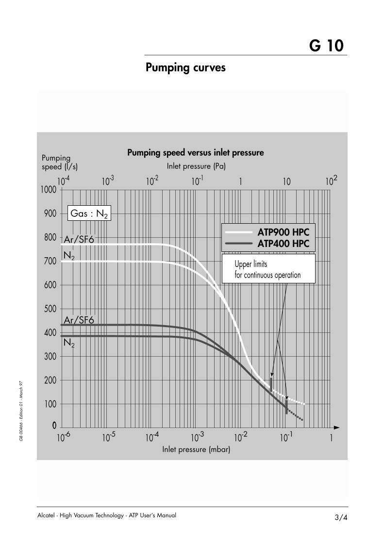
GB
0046
6 - E
ditio
n 01
- M
arch
97
Pumping curves
G 10
3/4Alcatel - High Vacuum Technology - ATP User’s Manual
0
Inlet pressure (Pa)
Inlet pressure (mbar)
Pumping speed (l/s)
0
500
400
300
200
100
1000
900
800
700
600
10-4 10-3 10-210-6 10-5 10-1 1
10-310-4 10-2 10-1 1 10 102
Pumping speed versus inlet pressure
ATP900 HPCATP400 HPC
Upper limitsfor continuous operation
Gas : N2
Ar/SF6
Ar/SF6
N2
N2
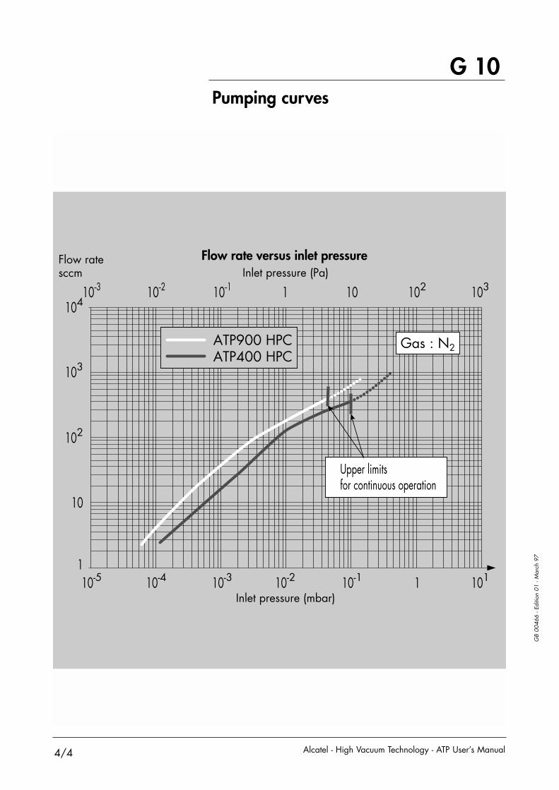
GB
0046
6 - E
ditio
n 01
- M
arch
97
Pumping curves
G 10
4/4 Alcatel - High Vacuum Technology - ATP User’s Manual
Inlet pressure (Pa)
Inlet pressure (mbar)
Flow ratesccm
1
10
102
103
104
10-5 10-4 10-3 10-2 10-1 1 101
10-3 10-2 10-1 1 10 102 103
Flow rate versus inlet pressure
ATP900 HPCATP400 HPC
Upper limitsfor continuous operation
Gas : N2

Alcatel Vacuum Technology France 98, avenue de Brogny - BP 2069 - 74009 Annecy cedex – France - Tel. (33) 4 50 65 77 77 - Fax. (33) 4 50 65 77 89
Web site :www.adixen.com
CHINAAlcatel Vacuum Technology, ShanghaiN°82 Lane 887 Zuchongzhi RoadZhangjiang High-Tech Park,Shanghai 201203 - P.R. ChinaTel. (86) 21 5027 0628Fax. (86) 21 3895 3815
FRANCEAlcatel Vacuum Technology France98, avenue de Brogny - BP 206974009 Annecy cedexTel. (33) 4 50 65 77 77Fax. (33) 4 50 65 77 89
GERMANYAlcatel Hochvakuumtechnik GmbHAm Kreuzeck 10 - Postfach 115197877 WertheimTel. (49) 9342 9610 00Fax. (49) 9342 9610 30
ITALYAlcatel Vacuum SystemsVia Trento, 3020059 Vimercate (Mi)Tel. (39) 0396 86 38 55Fax. (39) 039 66 71 25
JAPANAlcatel Vacuum Technology Japan4-3-10 Shimokodanaka,Nakahara-kuKawasaki, Kanagawa 211-0041Tel. (81) 44-797-5920Fax. (81) 44-797-5932
KOREAAlcatel Vacuum Technology Korea447 Banwol-dong, Hawsung-si, Kyungki-do,445-330, KoreaTel. (82) 031-206-6277Fax. (82) 031-204-6279
NETHERLANDSALCATEL Vacuum Technology BeneluxLandzichtweg 60NL 4105 DP CulemborgTHE NETHERLANDSTel. (31) 345 478 400Fax. (31) 345 531 076
SINGAPOREAlcatel Singapore Pte Ltd49 Jalan Pemimpin#01-01 APS Industrial Building577203 SingaporeTel. (65) 62540828Fax. (65) 62547018
SWEDENAdixen Sensistor AB.Box 76 - SE-581 02 LinköpingSWEDENTel. 46 (0)13 35 59 00Fax. 46 (0)13 35 59 01
TAIWANAlcatel Vacuum TaiwanNo. 169-3, Sec.1, Kang-Leh RdSong-Lin Village, Hsin-Feng 304Hsin-Chu County, Taiwan -R.O.C.Tel. (886) 35599230Fax.(886) 35599231
UNITED KINGDOMAlcatel Vacuum Technology UK Ltd8 Bain Square - Kirkton CampusLivingston - West LothianEH54 7DQ ScotlandTel. (44) 1 506 418 000Fax. (44) 1 506 418 002
USAAlcatel Vacuum Products67, Sharp StreetHingham - MA 02043Tel. (1) 781 331 4200Fax. (1) 781 331 4230