lesson 18 phasors & complex numbers in ac. learning objectives define and graph complex numbers...
TRANSCRIPT

Lesson 18Phasors & Complex Numbers in AC

Learning Objectives
Define and graph complex numbers in rectangular and polar form. Perform addition, subtraction, multiplication and division using
complex numbers and illustrate them using graphical methods. Define a phasor and use phasors to represent sinusoidal voltages
and currents. Define time domain and phasor (frequency) domain Represent a sinusoidal voltage or current as a complex number in
polar and rectangular form. Use the phasor domain to add/subtract AC voltages and currents. Determine when a sinusoidal waveform leads or lags another.
Graph a phasor diagram that illustrates phase relationships.

Complex numbers
A complex number is a number of the form C = a + jb where a and b are real and j =
a is the real part of C and b is the imaginary part.
Complex numbers are merely an invention designed to allow us to talk about the quantity j.
j is used in EE to represent the imaginary component to avoid confusion with CURRENT (i)
1

Geometric Representation
C = 6 + j8(rectangular form)
C = 1053.13º(polar form)

Conversion Between Forms
To convert between forms where
apply the following relations
(rectangular form)
(polar form)
a jb
C
C
C
2 2
1
cos
sin
tan
a C
b C
C a b
b
a
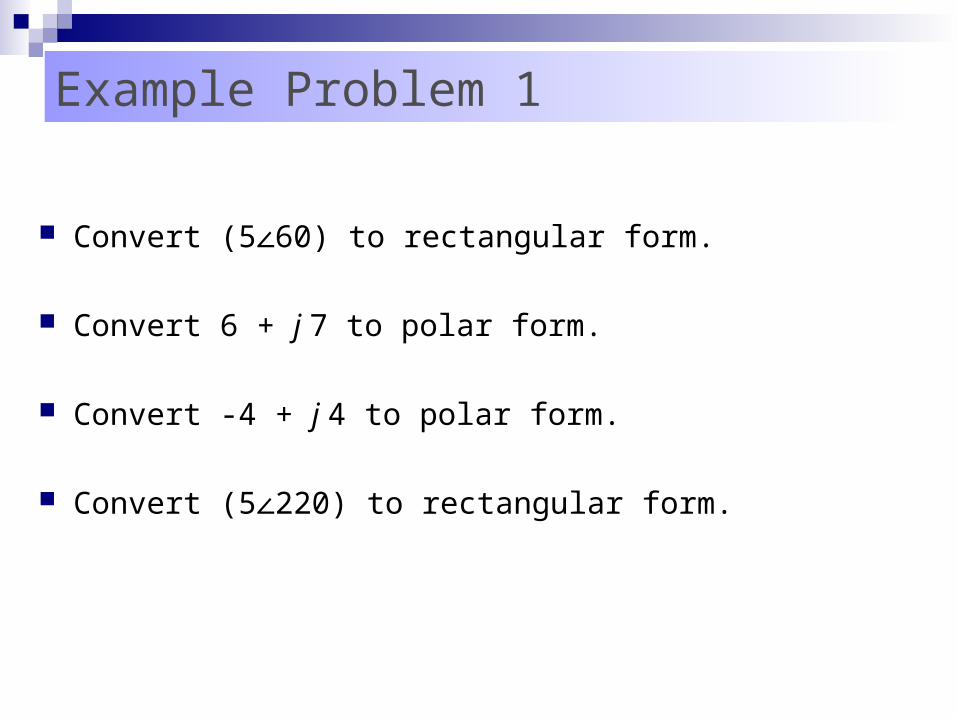
Example Problem 1
Convert (5 60) to rectangular form. ∠
Convert 6 + j 7 to polar form.
Convert -4 + j 4 to polar form.
Convert (5 220) to rectangular form.∠
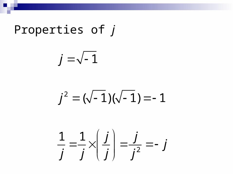
Properties of j
2
2
1
( 1)( 1) 1
1 1
j
j
j jj
j j j j

Addition and Subtraction of Complex Numbers
Easiest to perform in rectangular form Add/subtract real and imaginary parts separately
(6 12) (7 2) (6 7) (12 2) 13 14
(6 12) (7 2) (6 7) (12 2) 1 10
j j j j
j j j j
= =
= =
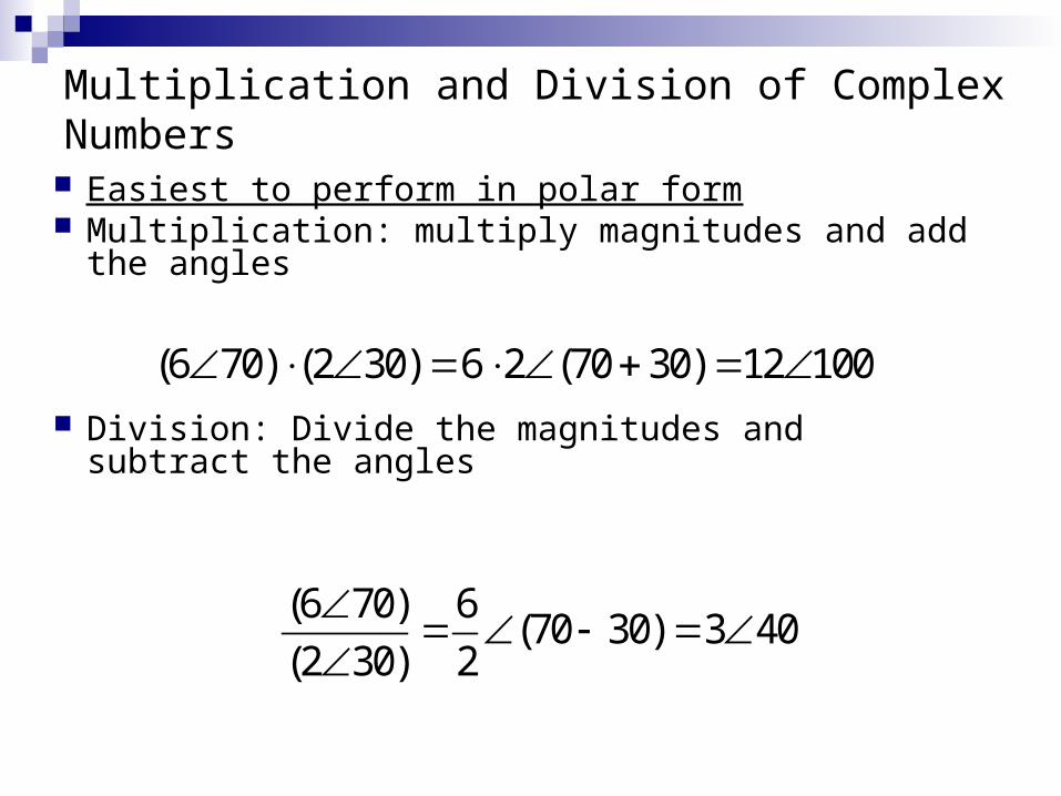
Multiplication and Division of Complex Numbers
Easiest to perform in polar form Multiplication: multiply magnitudes and add the angles
Division: Divide the magnitudes and subtract the angles
(6 70) (2 30) 6 2 (70 30) 12 100
(6 70) 6(70 30) 3 40
(2 30) 2

Example Problem 2
Given A =1 +j1 and B =2 – j3 Determine A+B and A-B.
Given A =1.4145° and B =3.61-56° Determine A/B and A*B.

Reciprocals and Conjugates The reciprocal of C = C , is
The conjugate of C is denoted C*, which has the same real value but the opposite imaginary part:
a jb C
a jb C
C
C
1 1 C C

Example Problem 3
And now you can try with your TI!!
(3-i4) + (10 44) ∠ ANS: 10.6 16.1 ∠ ANS: 10.2 + 2.9i
(22000+i13)/(3 -17) ANS: 7.3E3 17.0 ∠ ∠ Convert 95-12j to polar: ANS: 95.8 -7.2∠

Phasor Transform
To solve problems that involve sinusoids (such as AC voltages and currents) we use the phasor transform.
We transform sinusoids into complex numbers in polar form, solve the problem using complex arithmetic (as described), and then transform the result back to a sinusoid.

THE SINUSOIDAL WAVEFORM
Generating a sinusoidal waveform through the vertical projection of a rotating vector.

Phasors A phasor is a rotating vector whose projection
on the vertical axis can be used to represent a sinusoid.
The length of the phasor is amplitude of the sinusoid (Vm)
The angular velocity of the phasor is

Representing AC Signals with Complex Numbers
By replacing e(t) with it’s phasor equivalent E, we have transformed the source from the time domain to the phasor domain.
Phasors allow us to convert from differential equations to simple algebra.
KVL and KCL still work in phasor domain.

RMSV
Using phasors to represent AC voltage and current
VV
2PK
RMS
( ) V sin( 30 ) PKv t t
Looking at the sinusoid eqn, determine VPk and phase offset .
Using VPK, determine VRMS using the formula: “The equivalent dc value of a sinusoidal current or voltage is
0.707 of its peak value”
The phasor is then

Representing AC Signals with Complex Numbers
Phasor representations can be viewed as a complex number in polar form.
( ) 2 sin( )me t E t E = Erms

Example Problem 4
i1 = 20 sin (t) mA.
i2 = 10 sin (t+90˚) mA.
i3 = 30 sin (t - 90˚) mA.
Determine the equation for iT.

Phase Difference
Phase difference is angular displacement between waveforms of same frequency.
If angular displacement is 0° then waveforms are in phase
If angular displacement is not 0o, they are out of phase by amount of displacement

Phase Difference
If v1 = 5 sin(100t) and v2 = 3 sin(100t - 30°), v1 leads v2 by 30°

Phase Difference w/ Phasors The waveform generated by the leading
phasor leads the waveform generated by the lagging phasor.

Formulas from Trigonometry Sometimes signals are expressed in
cosines instead of sines.
cos( ) sin( 90 )
sin( ) cos( 90 )
cos( 180 ) cos( )
sin( 180 ) sin( )
cos( 70 ) sin( 160 ) sin( 20 )
t t
t t
t t
t t
t t t

Example Problem 5
Draw the phasor diagram, determine phase relationship, and sketch the waveform for the following:
i = 40 sin(t + 80º) and v = -30 sin(t - 70º)