levelflex m fmp43fotonika.kiev.ua/pdf/fmp43.pdflevelflex m fmp43 4 endress+hauser output the...
TRANSCRIPT

TI424F/00/en/03.09
No. 71074951
Technical Information
Levelflex M FMP43Run Time Measurement
Guided Level-Radar; Smart Transmitter for continuous level
measurement in liquids in hygienic applications.
Application
The Levelflex M FMP43 is used for continuous level
measurement of liquids in applications with special
hygienic requirements:
Materials
• All wetted components are FDA-listed and tested in
accordance with USP Cl. VI.
• Choice of mechanically polished or electropolished
metal surfaces up to 0.38 μm and low Δ ferrite content.
Design
• The design is flush-mounted and gap-free and meets
ASME BPE requirements.
• The probe is completely dismountable; the probe rod,
process connection and seals are replaceable.
• Aseptic process connections from DN25 (1") are
available.
• The probe is autoclavable and suitable for CIP, SIP.
Approvals (hygiene)
• Approvals according to 3A and EHEDG
• Certificate of Compliance (CoC)
The following interfaces are available for system
integration:
• HART (standard) with 4 to 20 mA analog;
PROFIBUS PA, FOUNDATION Fieldbus
Your benefits
• Measurement independent of product properties
such as:
– density,
– dielectric constant,
– conductivity.
• Measurement possible despite very turbulent
surfaces or foam.
• Easy menu-guided onsite operation via four-line plain
text display.
• Convenient remote operation, diagnosis and
documentation of the measuring point via the
FieldCare operating program which is provided free of
charge.
• Optional remote display and operation.
• Envelope curve presentation onsite on the display for
easy diagnosis.
• Electronics can be replaced without opening the tank.
• Application in safety related systems (overspill
protection) with requirements for functional safety up
to SIL 2 in accordance to IEC 61508/IEC 61511-1.
• Approvals:
– Europe: ATEX
– North America: FM, CSA
– China: NEPSI (in preparation)
Levelflex M FMP43
2 Endress+Hauser
Table of contents
Function and system design. . . . . . . . . . . . . . . . . . . . . 3
Measuring principle . . . . . . . . . . . . . . . . . . . . . . . . . . . . . . . . . . . 3
Equipment architecture . . . . . . . . . . . . . . . . . . . . . . . . . . . . . . . . 4
Input . . . . . . . . . . . . . . . . . . . . . . . . . . . . . . . . . . . . . . 8
Measured variable . . . . . . . . . . . . . . . . . . . . . . . . . . . . . . . . . . . . 8
Measuring range . . . . . . . . . . . . . . . . . . . . . . . . . . . . . . . . . . . . . . 8
Blocking distance . . . . . . . . . . . . . . . . . . . . . . . . . . . . . . . . . . . . . 8
Used frequency spectrum . . . . . . . . . . . . . . . . . . . . . . . . . . . . . . . 8
Output . . . . . . . . . . . . . . . . . . . . . . . . . . . . . . . . . . . . . 9
Output signal . . . . . . . . . . . . . . . . . . . . . . . . . . . . . . . . . . . . . . . . 9
Signal on alarm . . . . . . . . . . . . . . . . . . . . . . . . . . . . . . . . . . . . . . 9
Linearization . . . . . . . . . . . . . . . . . . . . . . . . . . . . . . . . . . . . . . . . 9
Data of the FOUNDATION Fieldbus interface . . . . . . . . . . . . . . . . 9
Auxiliary energy . . . . . . . . . . . . . . . . . . . . . . . . . . . . 11
Electrical connection . . . . . . . . . . . . . . . . . . . . . . . . . . . . . . . . . 11
Ground connection . . . . . . . . . . . . . . . . . . . . . . . . . . . . . . . . . . 11
Cable gland . . . . . . . . . . . . . . . . . . . . . . . . . . . . . . . . . . . . . . . . 11
Terminals . . . . . . . . . . . . . . . . . . . . . . . . . . . . . . . . . . . . . . . . . . 11
Terminal assignment . . . . . . . . . . . . . . . . . . . . . . . . . . . . . . . . . 12
Fieldbus plug connectors . . . . . . . . . . . . . . . . . . . . . . . . . . . . . . 13
Load HART . . . . . . . . . . . . . . . . . . . . . . . . . . . . . . . . . . . . . . . . 14
Supply voltage . . . . . . . . . . . . . . . . . . . . . . . . . . . . . . . . . . . . . . 14
Cable entry . . . . . . . . . . . . . . . . . . . . . . . . . . . . . . . . . . . . . . . . 14
Power consumption . . . . . . . . . . . . . . . . . . . . . . . . . . . . . . . . . . 14
Current consumption . . . . . . . . . . . . . . . . . . . . . . . . . . . . . . . . . 15
FISCO . . . . . . . . . . . . . . . . . . . . . . . . . . . . . . . . . . . . . . . . . . . . 15
Overvoltage protector . . . . . . . . . . . . . . . . . . . . . . . . . . . . . . . . . 15
Performance characteristics. . . . . . . . . . . . . . . . . . . . 16
Reference operating conditions . . . . . . . . . . . . . . . . . . . . . . . . . . 16
Maximum measured error . . . . . . . . . . . . . . . . . . . . . . . . . . . . . 16
Resolution . . . . . . . . . . . . . . . . . . . . . . . . . . . . . . . . . . . . . . . . . 17
Reaction time . . . . . . . . . . . . . . . . . . . . . . . . . . . . . . . . . . . . . . . 17
Influence of ambient temperature . . . . . . . . . . . . . . . . . . . . . . . . 17
Operating conditions: Installation . . . . . . . . . . . . . . . 18
General instructions . . . . . . . . . . . . . . . . . . . . . . . . . . . . . . . . . . 18
Cleaning of the probe . . . . . . . . . . . . . . . . . . . . . . . . . . . . . . . . . 19
Special instructions . . . . . . . . . . . . . . . . . . . . . . . . . . . . . . . . . . 20
Notes on special installation situations . . . . . . . . . . . . . . . . . . . . 21
Installation for difficult to access process connections . . . . . . . . . 22
Operating conditions: Environment. . . . . . . . . . . . . . 23
Ambient temperature range . . . . . . . . . . . . . . . . . . . . . . . . . . . . 23
Ambient temperature limits . . . . . . . . . . . . . . . . . . . . . . . . . . . . 23
Storage temperature . . . . . . . . . . . . . . . . . . . . . . . . . . . . . . . . . . 23
Climate class . . . . . . . . . . . . . . . . . . . . . . . . . . . . . . . . . . . . . . . 23
Degree of protection . . . . . . . . . . . . . . . . . . . . . . . . . . . . . . . . . . 23
Vibration resistance . . . . . . . . . . . . . . . . . . . . . . . . . . . . . . . . . . 23
Cleaning of the probe . . . . . . . . . . . . . . . . . . . . . . . . . . . . . . . . . 23
Electromagnetic compatibility (EMC) . . . . . . . . . . . . . . . . . . . . . 23
Operating conditions: Process . . . . . . . . . . . . . . . . . . 24
Process temperature range . . . . . . . . . . . . . . . . . . . . . . . . . . . . . 24
Process pressure . . . . . . . . . . . . . . . . . . . . . . . . . . . . . . . . . . . . . 24
Materials used in the process . . . . . . . . . . . . . . . . . . . . . . . . . . . 24
Dielectric constant . . . . . . . . . . . . . . . . . . . . . . . . . . . . . . . . . . . 24
Mechanical construction . . . . . . . . . . . . . . . . . . . . . . 25
Design, dimensions . . . . . . . . . . . . . . . . . . . . . . . . . . . . . . . . . . 25
General information on flanges . . . . . . . . . . . . . . . . . . . . . . . . . . 29
Tolerance of probe length . . . . . . . . . . . . . . . . . . . . . . . . . . . . . . 29
Weight . . . . . . . . . . . . . . . . . . . . . . . . . . . . . . . . . . . . . . . . . . . 29
Material . . . . . . . . . . . . . . . . . . . . . . . . . . . . . . . . . . . . . . . . . . . 29
Process connection . . . . . . . . . . . . . . . . . . . . . . . . . . . . . . . . . . 29
Probe . . . . . . . . . . . . . . . . . . . . . . . . . . . . . . . . . . . . . . . . . . . . . 29
Human interface . . . . . . . . . . . . . . . . . . . . . . . . . . . . 30
Operation concept . . . . . . . . . . . . . . . . . . . . . . . . . . . . . . . . . . . 30
Display elements . . . . . . . . . . . . . . . . . . . . . . . . . . . . . . . . . . . . 30
Operating elements . . . . . . . . . . . . . . . . . . . . . . . . . . . . . . . . . . 31
Onsite operation . . . . . . . . . . . . . . . . . . . . . . . . . . . . . . . . . . . . 32
Remote operation . . . . . . . . . . . . . . . . . . . . . . . . . . . . . . . . . . . . 32
Remote operation . . . . . . . . . . . . . . . . . . . . . . . . . . . . . . . . . . . . 33
Certificates and approvals . . . . . . . . . . . . . . . . . . . . . 35
CE mark . . . . . . . . . . . . . . . . . . . . . . . . . . . . . . . . . . . . . . . . . . 35
Ex approval . . . . . . . . . . . . . . . . . . . . . . . . . . . . . . . . . . . . . . . . 35
Suitability for hygenic processes . . . . . . . . . . . . . . . . . . . . . . . . 36
Pharma (CoC). . . . . . . . . . . . . . . . . . . . . . . . . . . . . . . . . . . . . . 36
Overspill protection . . . . . . . . . . . . . . . . . . . . . . . . . . . . . . . . . . 36
Telecommunications . . . . . . . . . . . . . . . . . . . . . . . . . . . . . . . . . 36
External standards and guidelines . . . . . . . . . . . . . . . . . . . . . . . . 36
Ordering information. . . . . . . . . . . . . . . . . . . . . . . . . 37
Levelflex M FMP43 . . . . . . . . . . . . . . . . . . . . . . . . . . . . . . . . . . 37
Accessories . . . . . . . . . . . . . . . . . . . . . . . . . . . . . . . . 40
Weather protection cover . . . . . . . . . . . . . . . . . . . . . . . . . . . . . . 40
Weld-in adapter . . . . . . . . . . . . . . . . . . . . . . . . . . . . . . . . . . . . . 40
Remote display and operation FHX40 . . . . . . . . . . . . . . . . . . . . . 41
Commubox FXA191 HART . . . . . . . . . . . . . . . . . . . . . . . . . . . . 42
Commubox FXA195 HART . . . . . . . . . . . . . . . . . . . . . . . . . . . . 42
Commubox FXA291 . . . . . . . . . . . . . . . . . . . . . . . . . . . . . . . . . 42
ToF Adapter FXA291 . . . . . . . . . . . . . . . . . . . . . . . . . . . . . . . . . 42
Protective cover . . . . . . . . . . . . . . . . . . . . . . . . . . . . . . . . . . . . . 42
Calibration kit . . . . . . . . . . . . . . . . . . . . . . . . . . . . . . . . . . . . . . 42
Additional documentation . . . . . . . . . . . . . . . . . . . . . 43
Fields of activities . . . . . . . . . . . . . . . . . . . . . . . . . . . . . . . . . . . . 43
Competence brochure . . . . . . . . . . . . . . . . . . . . . . . . . . . . . . . . 43
Technical Information . . . . . . . . . . . . . . . . . . . . . . . . . . . . . . . . 43
Operating Instructions . . . . . . . . . . . . . . . . . . . . . . . . . . . . . . . . 43
Patents . . . . . . . . . . . . . . . . . . . . . . . . . . . . . . . . . . . . . . . . . . . 43
Levelflex M FMP43
Endress+Hauser 3
Function and system design
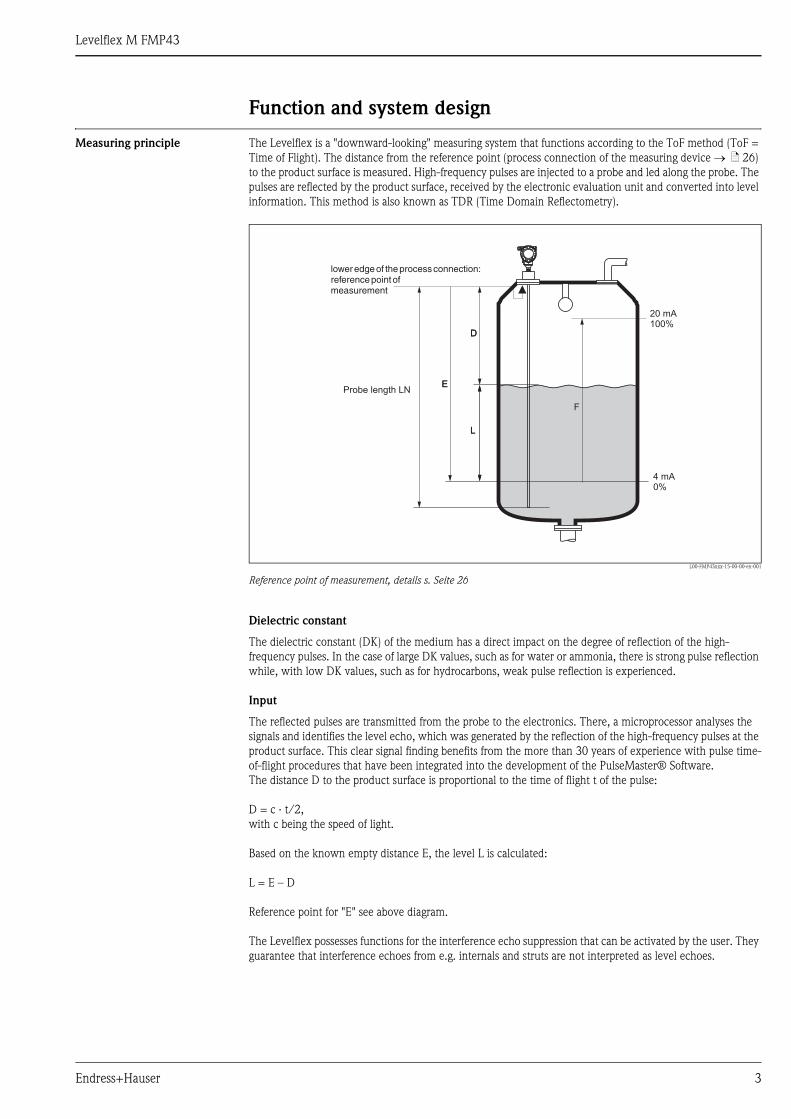
Measuring principle The Levelflex is a "downward-looking" measuring system that functions according to the ToF method (ToF =
Time of Flight). The distance from the reference point (process connection of the measuring device → ä 26)
to the product surface is measured. High-frequency pulses are injected to a probe and led along the probe. The
pulses are reflected by the product surface, received by the electronic evaluation unit and converted into level
information. This method is also known as TDR (Time Domain Reflectometry).
L00-FMP43xxx-15-00-00-en-001
Reference point of measurement, details s. Seite 26
Dielectric constant
The dielectric constant (DK) of the medium has a direct impact on the degree of reflection of the high-
frequency pulses. In the case of large DK values, such as for water or ammonia, there is strong pulse reflection
while, with low DK values, such as for hydrocarbons, weak pulse reflection is experienced.
Input
The reflected pulses are transmitted from the probe to the electronics. There, a microprocessor analyses the
signals and identifies the level echo, which was generated by the reflection of the high-frequency pulses at the
product surface. This clear signal finding benefits from the more than 30 years of experience with pulse time-
of-flight procedures that have been integrated into the development of the PulseMaster® Software.
The distance D to the product surface is proportional to the time of flight t of the pulse:
D = c · t/2,
with c being the speed of light.
Based on the known empty distance E, the level L is calculated:
L = E – D
Reference point for "E" see above diagram.
The Levelflex possesses functions for the interference echo suppression that can be activated by the user. They
guarantee that interference echoes from e.g. internals and struts are not interpreted as level echoes.
DD
LL
20 mA100%
4 mA0%
F
EEProbe length LN
loweredgeof theprocessconnection:referencepointofmeasurement
Levelflex M FMP43
4 Endress+Hauser
Output
The Levelflex is initially adjusted at the factory to the probe length ordered, so that in most cases only the
application parameters, that automatically adapt the device to the measuring conditions, need to be entered.
For models with current output, the factory adjustment for zero point E and span is F 4 mA and 20 mA, for
digital outputs and the display module 0 % and 100 %. A linearization function with max. 32 points, that is
based on a manually or semi-automatically input table, can be activated onsite or via remote operation. This
function enables, for example, the conversion of the level into units of volume or weight.
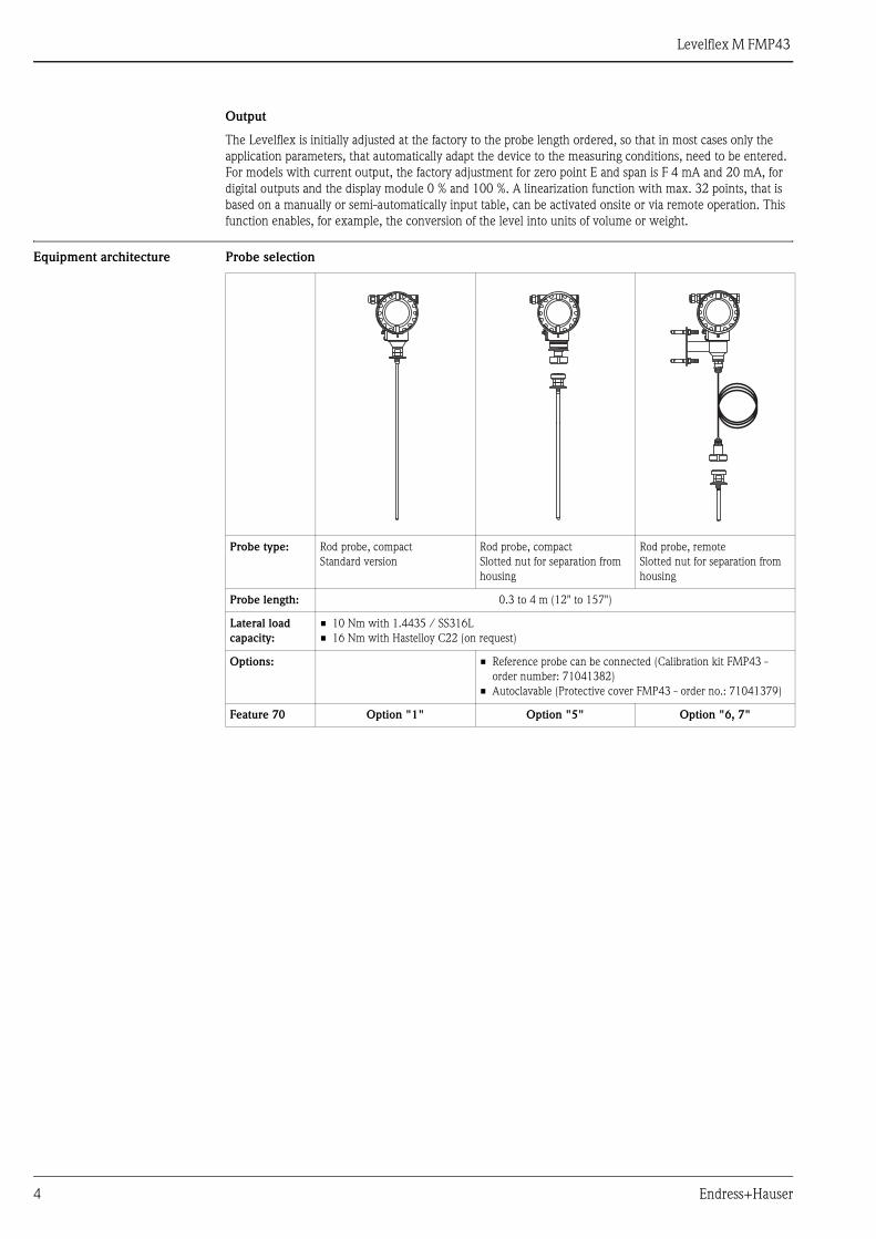
Equipment architecture Probe selection
Probe type: Rod probe, compact
Standard version
Rod probe, compact
Slotted nut for separation from
housing
Rod probe, remote
Slotted nut for separation from
housing
Probe length: 0.3 to 4 m (12" to 157")
Lateral load
capacity:
• 10 Nm with 1.4435 / SS316L
• 16 Nm with Hastelloy C22 (on request)
Options: • Reference probe can be connected (Calibration kit FMP43 -
order number: 71041382)
• Autoclavable (Protective cover FMP43 - order no.: 71041379)
Feature 70 Option "1" Option "5" Option "6, 7"
Levelflex M FMP43
Endress+Hauser 5
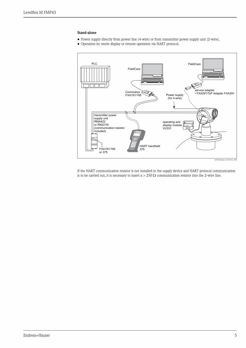
Stand-alone
• Power supply directly from power line (4-wire) or from transmitter power supply unit (2-wire).
• Operation by onsite display or remote operation via HART protocol.
L00-FMxxxxxx-14-00-06-en-008
If the HART communication resistor is not installed in the supply device and HART protocol communication
is to be carried out, it is necessary to insert a > 250 Ω communication resistor into the 2-wire line.
ENDRESS + HAUSER
E+–
%
ENDRESS + HAUSERRMA 422
1# % &
Copy
G H I
P Q R S
, ( ) ‘
A B C
Paste
PageOn
PageUp
DeleteBksp
Insert
J K L
T U V
_ < >
D E F
Hot Key
+ Hot Key
M N O
W X Y Z
+ * /
4
7
.
2
5
8
0
375FIELD COMMUNICATOR
3
6
9
-
9 6
DELTABAR: * * * * * * * *ONLINE
1 QUICK SETUP2 OPERATING MENU
4 SV 0 °C3 PV 352 mbar
HELP SAVE
dsdmdmdf das.
asdas faasas la.
FieldCare
FieldCare
HART handheld375FXA191/195
or 375
transmitter powersupply unitRMA422or RN221N(communication resistorincluded)
PLC
CommuboxFXA191/195
operating anddisplay moduleVU331
Power supply(for 4-wire)
service adapter• FXA291/ToF Adapter FXA291
Levelflex M FMP43
6 Endress+Hauser
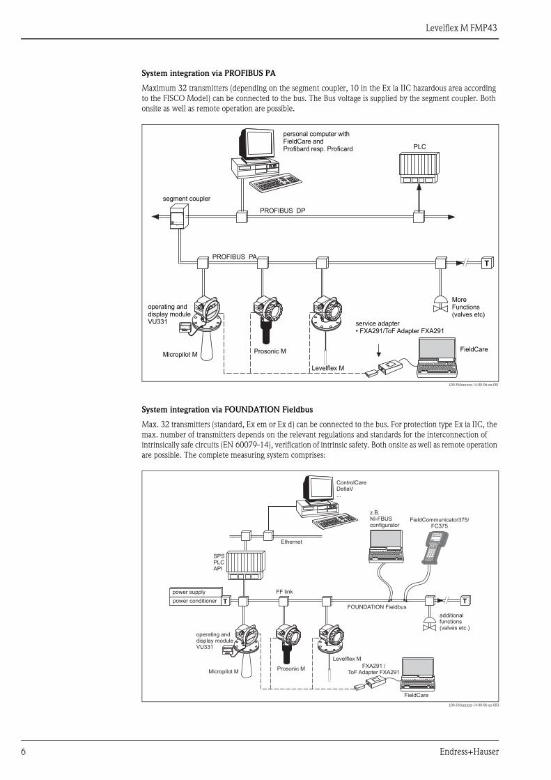
System integration via PROFIBUS PA
Maximum 32 transmitters (depending on the segment coupler, 10 in the Ex ia IIC hazardous area according
to the FISCO Model) can be connected to the bus. The Bus voltage is supplied by the segment coupler. Both
onsite as well as remote operation are possible.
L00-FMxxxxxx-14-00-06-en-001
System integration via FOUNDATION Fieldbus
Max. 32 transmitters (standard, Ex em or Ex d) can be connected to the bus. For protection type Ex ia IIC, the
max. number of transmitters depends on the relevant regulations and standards for the interconnection of
intrinsically safe circuits (EN 60079-14), verification of intrinsic safety. Both onsite as well as remote operation
are possible. The complete measuring system comprises:
L00-FMxxxxxx-14-00-06-en-003
ENDRESS + HAUSER
Micropilot M Prosonic M
Levelflex M
ENDRESS + HAUSER
E+–
%
T
PROFIBUS DP
PROFIBUS PA
FieldCare
personal computer withFieldCare andProfibard resp. Proficard
segment coupler
PLC
operating anddisplay moduleVU331
MoreFunctions(valves etc)
service adapter• FXA291/ToF Adapter FXA291
T T
ENDRESS + HAUSER
E+–
%
1# % &
Copy
G H I
P Q R S
, ( ) ‘
A B C
Paste
PageOn
PageUp
DeleteBksp
Insert
J K L
T U V
_ < >
D E F
Hot Key
+ Hot Key
M N O
W X Y Z
+ * /
4
7
.
2
5
8
0
375FIELD COMMUNICATOR
3
6
9
-
9 6
DELTABAR: * * * * * * * *ONLINE
1 QUICK SETUP2 OPERATING MENU
4 SV 0 °C3 PV 352 mbar
HELP SAVE
dsdmdmdf das.asdas faasas la.
Ethernet
SPSPLCAPI
FF link
FOUNDATION Fieldbus
Micropilot MProsonic M
Levelflex M
FieldCommunicator375/FC375
FXA291 /ToF Adapter FXA291
FieldCare
ControlCareDeltaV...
power supply
power conditioner
operating anddisplay moduleVU331
additionalfunctions(valves etc.)
z.B.NI-FBUSconfigurator
Levelflex M FMP43
Endress+Hauser 7
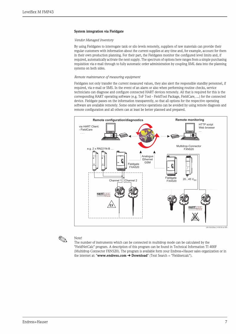
System integration via Fieldgate
Vendor Managed Inventory
By using Fieldgates to interrogate tank or silo levels remotely, suppliers of raw materials can provide their
regular customers with information about the current supplies at any time and, for example, account for them
in their own production planning. For their part, the Fieldgates monitor the configured level limits and, if
required, automatically activate the next supply. The spectrum of options here ranges from a simple purchasing
requisition via e-mail through to fully automatic order administration by coupling XML data into the planning
systems on both sides.
Remote maintenance of measuring equipment
Fieldgates not only transfer the current measured values, they also alert the responsible standby personnel, if
required, via e-mail or SMS. In the event of an alarm or also when performing routine checks, service
technicians can diagnose and configure connected HART devices remotely. All that is required for this is the
corresponding HART operating software (e.g. ToF Tool - FieldTool Package, FieldCare, ...) for the connected
device. Fieldgate passes on the information transparently, so that all options for the respective operating
software are available remotely. Some onsite service operations can be avoided by using remote diagnosis and
remote configuration and all others can at least be better planned and prepared.
L00-FXA520xx-14-00-06-en-009
! Note!
The number of instruments which can be connected in multidrop mode can be calculated by the
"FieldNetCalc" program. A description of this program can be found in Technical Information TI 400F
(Multidrop Connector FXN520). The program is available form your Endress+Hauser sales organization or in
the internet at: "www.endress.com É Download" (Text Search = "Fieldnetcalc").
-
FieldgateFXA520
ENDRESS+HAUSERRN 221N
ENDRESS+HAUSERRN 221N
.
FieldgateFXA520
20...45 VDC
FX
N520
FX
N520
Multidrop-ConnectorFXN520
HTTP scriptWeb browser…
AnalogueEthernet
GSM
e.g. 2 x RN221N-B …
Channel 1 Channel 2
via HART Client:- FieldCare. . .
Remote monitoringRemote configuration/diagnostics
Levelflex M FMP43
8 Endress+Hauser
Input
Measured variable The measured variable is the distance between the reference point (see Fig on Seite 26) and the product
surface.
Subject to the input zero point empty distance (E, see Fig. on Seite 3) the level is calculated.
Alternatively, the level can be converted by means of linearization (32 points) into other variables (volume,
mass).
Measuring range The measuring range spans the entire probe. The upper blocking distance set in the delivery status can be
adapted as required (see recommendations in the "Blocking distance" chapter). The specified accuracy of the
probe is reduced in the upper and lower range of the probe (see Table → ä 16), especially when using media
with a smaller dielectric constant (DK < 7).
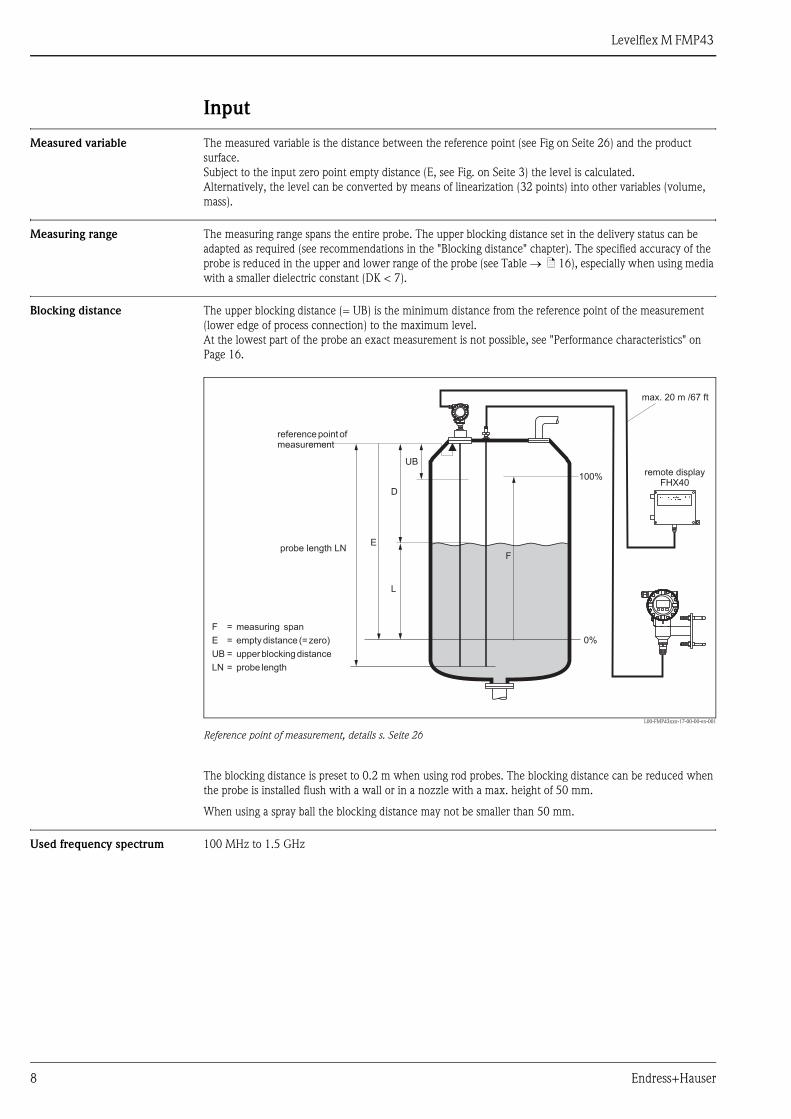
Blocking distance The upper blocking distance (= UB) is the minimum distance from the reference point of the measurement
(lower edge of process connection) to the maximum level.
At the lowest part of the probe an exact measurement is not possible, see "Performance characteristics" on
Page 16.
L00-FMP43xxx-17-00-00-en-001
Reference point of measurement, details s. Seite 26
The blocking distance is preset to 0.2 m when using rod probes. The blocking distance can be reduced when
the probe is installed flush with a wall or in a nozzle with a max. height of 50 mm.
When using a spray ball the blocking distance may not be smaller than 50 mm.
Used frequency spectrum 100 MHz to 1.5 GHz
100%
0%
F
UB
D
L
E
reference point ofmeasurement
max. 20 m /67 ft
remote displayFHX40
F = measuring span
E = empty distance (=zero)
UB = upper blocking distance
LN = probe length
probe length LN
Levelflex M FMP43
Endress+Hauser 9
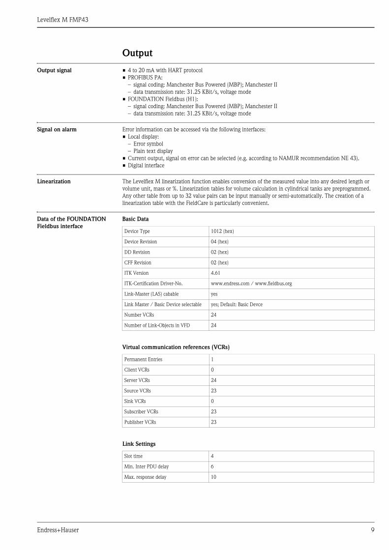
Output
Output signal • 4 to 20 mA with HART protocol
• PROFIBUS PA:
– signal coding: Manchester Bus Powered (MBP); Manchester II
– data transmission rate: 31.25 KBit/s, voltage mode
• FOUNDATION Fieldbus (H1):
– signal coding: Manchester Bus Powered (MBP); Manchester II
– data transmission rate: 31.25 KBit/s, voltage mode
Signal on alarm Error information can be accessed via the following interfaces:
• Local display:
– Error symbol
– Plain text display
• Current output, signal on error can be selected (e.g. according to NAMUR recommendation NE 43).
• Digital interface
Linearization The Levelflex M linearization function enables conversion of the measured value into any desired length or
volume unit, mass or %. Linearization tables for volume calculation in cylindrical tanks are preprogrammed.
Any other table from up to 32 value pairs can be input manually or semi-automatically. The creation of a
linearization table with the FieldCare is particularly convenient.
Data of the FOUNDATION
Fieldbus interface
Basic Data
Virtual communication references (VCRs)
Link Settings
Device Type 1012 (hex)
Device Revision 04 (hex)
DD Revision 02 (hex)
CFF Revision 02 (hex)
ITK Version 4.61
ITK-Certification Driver-No. www.endress.com / www.fieldbus.org
Link-Master (LAS) cabable yes
Link Master / Basic Device selectable yes; Default: Basic Devce
Number VCRs 24
Number of Link-Objects in VFD 24
Permanent Entries 1
Client VCRs 0
Server VCRs 24
Source VCRs 23
Sink VCRs 0
Subscriber VCRs 23
Publisher VCRs 23
Slot time 4
Min. Inter PDU delay 6
Max. response delay 10
Levelflex M FMP43
10 Endress+Hauser
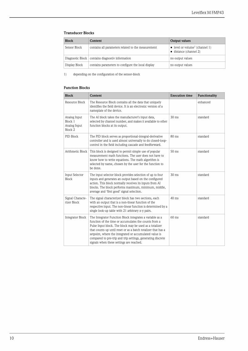
Transducer Blocks
Function Blocks
Block Content Output values
Sensor Block contains all parameters related to the measurement • level or volume1 (channel 1)
• distance (channel 2)
1) depending on the configuration of the sensor-block
Diagnsotic Block contains diagnostiv information no output values
Display Block contains parameters to configure the local display no output values
Block Content Execution time Functionality
Resource Block The Resource Block contains all the data that uniquely
identifies the field device. It is an electronic version of a
nameplate of the device.
enhanced
Analog Input
Block 1
Analog Input
Block 2
The AI block takes the manufacturer's input data,
selected by channel number, and makes it available to other
function blocks at its output.
30 ms standard
PID Block The PID block serves as proportional-integral-derivative
controller and is used almost universally to do closed-loop-
control in the field including cascade and feedforward.
80 ms standard
Arithmetic Block This block is designed to permit simple use of popular
measurement math functions. The user does not have to
know how to write equations. The math algorithm is
selected by name, chosen by the user for the function to
be done.
50 ms standard
Input Selector
Block
The input selector block provides selection of up to four
inputs and generates an output based on the configured
action. This block normally receives its inputs from AI
blocks. The block performs maximum, minimum, middle,
average and ‘first good’ signal selection.
30 ms standard
Signal Characte-
rizer Block
The signal characterizer block has two sections, each
with an output that is a non-linear function of the
respective input. The non-linear function is determined by a
single look-up table with 21 arbitrary x-y pairs.
40 ms standard
Integrator Block The Integrator Function Block integrates a variable as a
function of the time or accumulates the counts from a
Pulse Input block. The block may be used as a totalizer
that counts up until reset or as a batch totalizer that has a
setpoint, where the integrated or accumulated value is
compared to pre-trip and trip settings, generating discrete
signals when these settings are reached.
60 ms standard

Levelflex M FMP43
Endress+Hauser 11
Auxiliary energy
Electrical connection Terminal compartment
Three housings are available:
• Aluminum housing F12 with additionally sealed terminal compartment for:
– standard,
– Ex ia.
• Aluminum housing T12 with separate terminal compartment for:
– standard,
– Ex e,
– Ex d
– Ex ia (with overvoltage protection).
• Stainless steel 316L housing F23 for:
– standard,
– Ex ia.
After mounting, the housing can be turned 350° in order to simplify access to the display and the terminal
compartment.
L00-FMR2xxxx-04-00-00-en-019
Ground connection It is necessary to make a good ground connection to the ground terminal on the outside of the housing, in order
to achieve EMC security.
Cable gland
Terminals for wire cross-sections of 0.5 to 2.5 mm2
1 12 23 34 41 2 3 4
sealed terminalcompartment
F12 housing F23 housingT12 housing
Type Clamping area
Standard, Ex ia, IS Plastic M20x1.5 5 to 10 mm
Ex em, Ex nA Metal M20x1.5 7 to 10.5 mm
Levelflex M FMP43
12 Endress+Hauser
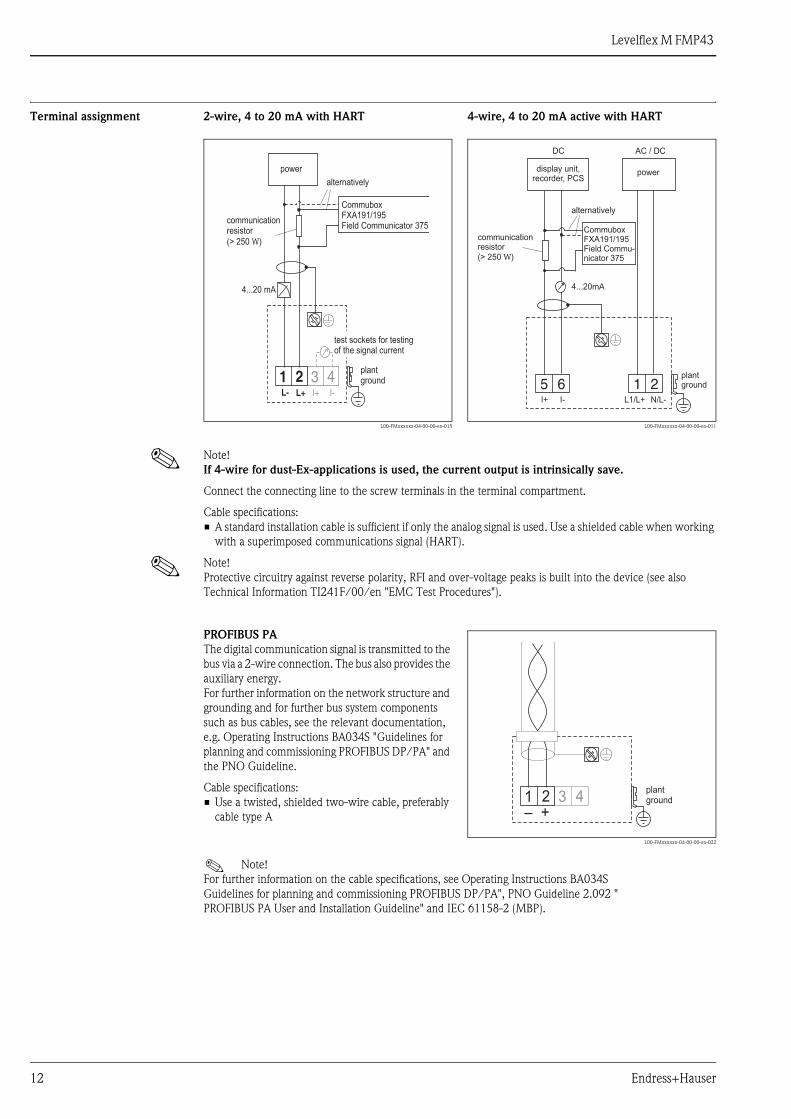
Terminal assignment
! Note!
If 4-wire for dust-Ex-applications is used, the current output is intrinsically save.
Connect the connecting line to the screw terminals in the terminal compartment.
Cable specifications:
• A standard installation cable is sufficient if only the analog signal is used. Use a shielded cable when working
with a superimposed communications signal (HART).
! Note!
Protective circuitry against reverse polarity, RFI and over-voltage peaks is built into the device (see also
Technical Information TI241F/00/en "EMC Test Procedures").
2-wire, 4 to 20 mA with HART 4-wire, 4 to 20 mA active with HART
L00-FMxxxxxx-04-00-00-en-015 L00-FMxxxxxx-04-00-00-en-011
3 4I+ I-
1 2L- L+
4...20 mA
CommuboxFXA191/195Field Communicator 375
communicationresistor(> 250 )W
alternatively
plantground
test sockets for testingof the signal current
power
5 6I+ I-
1 2L1/L+ N/L-
4...20mA
CommuboxFXA191/195Field Commu-nicator 375
communicationresistor(> 250 )W
alternatively
powerdisplay unit,recorder, PCS
AC / DCDC
plantground
PROFIBUS PA
The digital communication signal is transmitted to the
bus via a 2-wire connection. The bus also provides the
auxiliary energy.
For further information on the network structure and
grounding and for further bus system components
such as bus cables, see the relevant documentation,
e.g. Operating Instructions BA034S "Guidelines for
planning and commissioning PROFIBUS DP/PA" and
the PNO Guideline.
Cable specifications:
• Use a twisted, shielded two-wire cable, preferably
cable type A
L00-FMxxxxxx-04-00-00-en-022
! Note!
For further information on the cable specifications, see Operating Instructions BA034S
Guidelines for planning and commissioning PROFIBUS DP/PA", PNO Guideline 2.092 "
PROFIBUS PA User and Installation Guideline" and IEC 61158-2 (MBP).
3 41 2+–
plantground
Levelflex M FMP43
Endress+Hauser 13
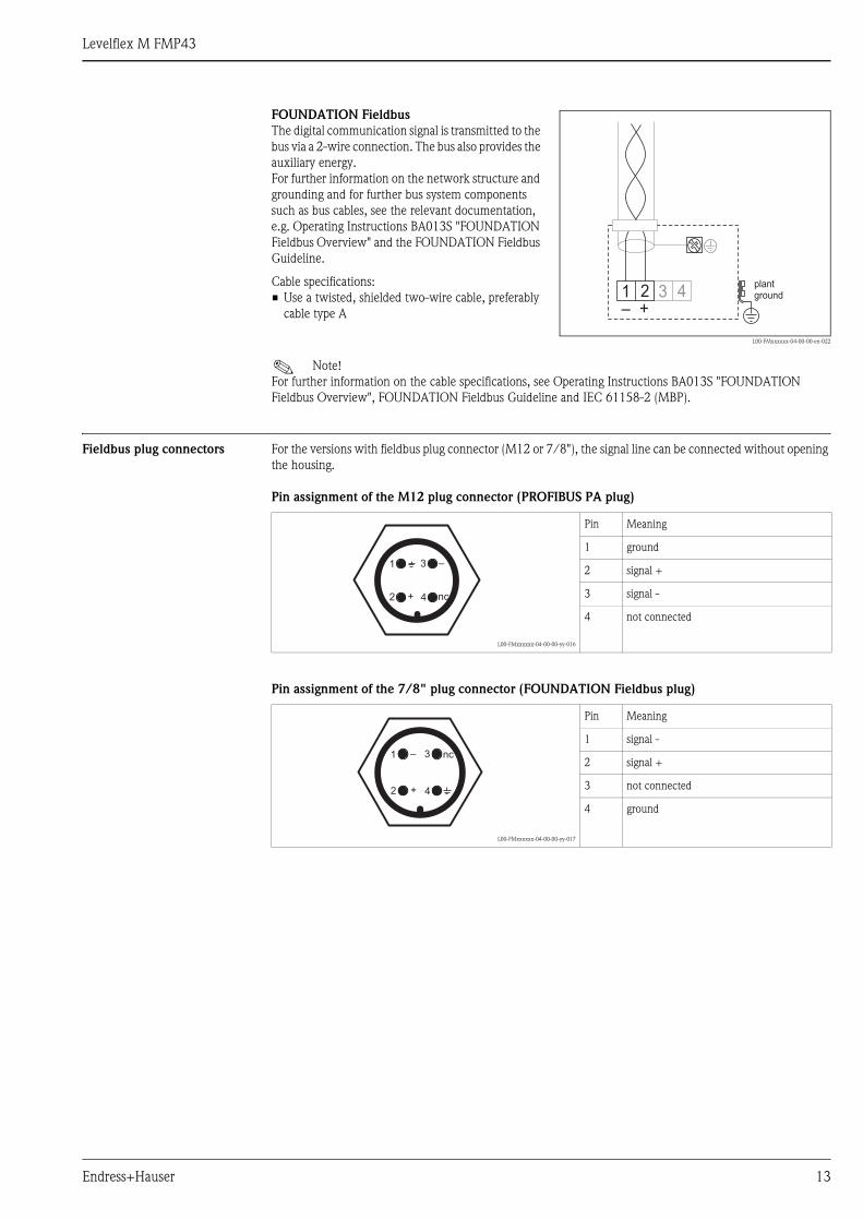
Fieldbus plug connectors For the versions with fieldbus plug connector (M12 or 7/8"), the signal line can be connected without opening
the housing.
Pin assignment of the M12 plug connector (PROFIBUS PA plug)
Pin assignment of the 7/8" plug connector (FOUNDATION Fieldbus plug)
FOUNDATION Fieldbus
The digital communication signal is transmitted to the
bus via a 2-wire connection. The bus also provides the
auxiliary energy.
For further information on the network structure and
grounding and for further bus system components
such as bus cables, see the relevant documentation,
e.g. Operating Instructions BA013S "FOUNDATION
Fieldbus Overview" and the FOUNDATION Fieldbus
Guideline.
Cable specifications:
• Use a twisted, shielded two-wire cable, preferably
cable type A
L00-FMxxxxxx-04-00-00-en-022
! Note!
For further information on the cable specifications, see Operating Instructions BA013S "FOUNDATION
Fieldbus Overview", FOUNDATION Fieldbus Guideline and IEC 61158-2 (MBP).
3 41 2+–
plantground
L00-FMxxxxxx-04-00-00-yy-016
Pin Meaning
1 ground
2 signal +
3 signal -
4 not connected
L00-FMxxxxxx-04-00-00-yy-017
Pin Meaning
1 signal -
2 signal +
3 not connected
4 ground
2
1 3
4+
–
nc
2
1 3
4+
– nc
Levelflex M FMP43
14 Endress+Hauser
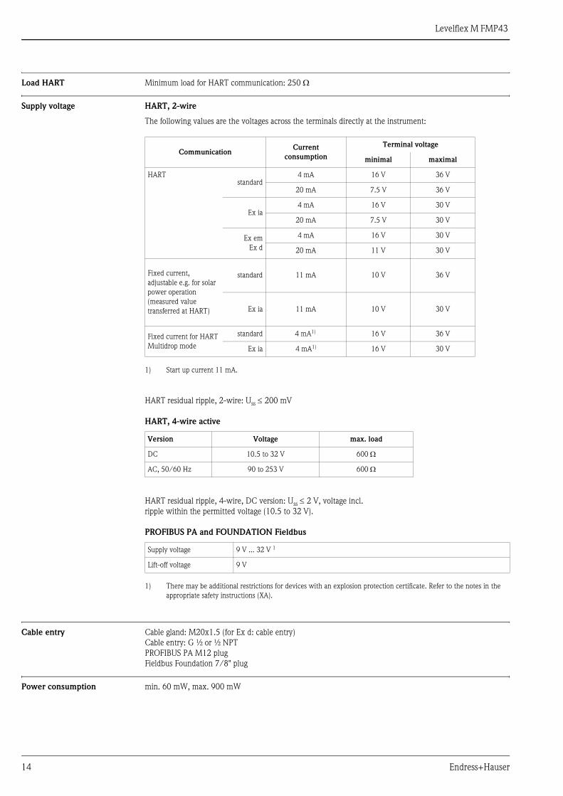
Load HART Minimum load for HART communication: 250 Ω
Supply voltage HART, 2-wire
The following values are the voltages across the terminals directly at the instrument:
HART residual ripple, 2-wire: Uss ≤ 200 mV
HART, 4-wire active
HART residual ripple, 4-wire, DC version: Uss ≤ 2 V, voltage incl.
ripple within the permitted voltage (10.5 to 32 V).
PROFIBUS PA and FOUNDATION Fieldbus
Cable entry Cable gland: M20x1.5 (for Ex d: cable entry)
Cable entry: G ½ or ½ NPT
PROFIBUS PA M12 plug
Fieldbus Foundation 7/8" plug
Power consumption min. 60 mW, max. 900 mW
CommunicationCurrent
consumption
Terminal voltage
minimal maximal
HARTstandard
4 mA 16 V 36 V
20 mA 7.5 V 36 V
Ex ia4 mA 16 V 30 V
20 mA 7.5 V 30 V
Ex em
Ex d
4 mA 16 V 30 V
20 mA 11 V 30 V
Fixed current,
adjustable e.g. for solar
power operation
(measured value
transferred at HART)
standard 11 mA 10 V 36 V
Ex ia 11 mA 10 V 30 V
Fixed current for HART
Multidrop mode
standard 4 mA1)
1) Start up current 11 mA.
16 V 36 V
Ex ia 4 mA1) 16 V 30 V
Version Voltage max. load
DC 10.5 to 32 V 600 Ω
AC, 50/60 Hz 90 to 253 V 600 Ω
Supply voltage 9 V ... 32 V 1
1) There may be additional restrictions for devices with an explosion protection certificate. Refer to the notes in the
appropriate safety instructions (XA).
Lift-off voltage 9 V
Levelflex M FMP43
Endress+Hauser 15
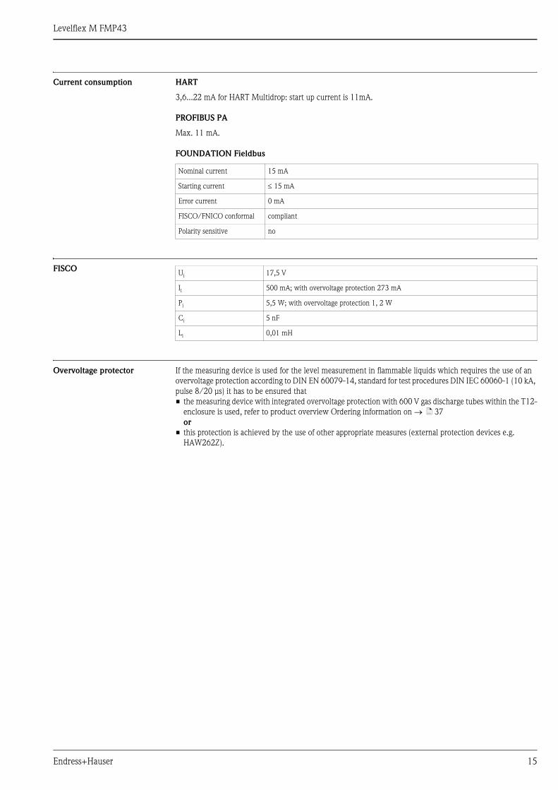
Current consumption HART
3,6...22 mA for HART Multidrop: start up current is 11mA.
PROFIBUS PA
Max. 11 mA.
FOUNDATION Fieldbus
FISCO
Overvoltage protector If the measuring device is used for the level measurement in flammable liquids which requires the use of an
overvoltage protection according to DIN EN 60079-14, standard for test procedures DIN IEC 60060-1 (10 kA,
pulse 8/20 μs) it has to be ensured that
• the measuring device with integrated overvoltage protection with 600 V gas discharge tubes within the T12-
enclosure is used, refer to product overview Ordering information on → ä 37
or
• this protection is achieved by the use of other appropriate measures (external protection devices e.g.
HAW262Z).
Nominal current 15 mA
Starting current ≤ 15 mA
Error current 0 mA
FISCO/FNICO conformal compliant
Polarity sensitive no
Ui 17,5 V
Ii 500 mA; with overvoltage protection 273 mA
Pi 5,5 W; with overvoltage protection 1, 2 W
Ci 5 nF
Li 0,01 mH
Levelflex M FMP43
16 Endress+Hauser
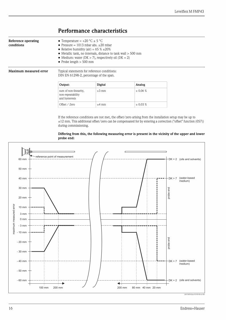
Performance characteristics
Reference operating
conditions
• Temperature = +20 °C ± 5 °C
• Pressure = 1013 mbar abs. ±20 mbar
• Relative humidity (air) = 65 % ±20%
• Metallic tank, no internals, distance to tank wall > 500 mm
• Medium: water (DK > 7), respectively oil (DK = 2)
• Probe length > 500 mm
Maximum measured error Typical statements for reference conditions:
DIN EN 61298-2, percentage of the span.
If the reference conditions are not met, the offset/zero arising from the installation setup may be up to
±12 mm. This additional offset/zero can be compensated for by entering a correction ("offset" function (057))
during commissioning.
Differing from this, the following measuring error is present in the vicinity of the upper and lower
probe end:
Output: Digital Analog
sum of non-linearity,
non-repeatability
and hysteresis
±3 mm ± 0.06 %
Offset / Zero ±4 mm ± 0.03 %
L00-FMP43xxx-05-00-00-en-001
3 mm
0 mm
- 3 mm
100 mm 200 mm 80 mm200 mm 40 mm 20 mm
10 mm
- 10 mm
20 mm
- 20 mm
30 mm
- 30 mm
40 mm
- 40 mm
50 mm
- 50 mm
DK > 7
DK > 7
60 mm
- 60 mm
DK = 2
DK = 2
reference point of measurement
pro
be
end
maxim
um
measure
derr
or
pro
be
end
(water-basedmedium)
(water-basedmedium)
(oils and solvents)
( )oils and solvents

Levelflex M FMP43
Endress+Hauser 17
Resolution • Digital: 1 mm
• Analog: 0.03 % of measuring range
Reaction time The reaction time depends on the configuration.
Shortest time:
• 2-wire electronics: 1 s
• 4-wire electronics: 0.7 s
Influence of ambient
temperature
The measurements are carried out in accordance with EN 61298-3:
• digital output (HART, PROFIBUS PA, FOUNDATION Fieldbus):
– average TK: 0.6 mm/10 K, max. ±3.5 mm over the entire temperature range -40 °C to +80 °C
2-wire
• Current output (additional error, in reference to the span of 16 mA):
– Zero point (4 mA)
average TK: 0.032 %/10 K, max. 0.35 % over the entire temperature range -40 °C to +80 °C
– Span (20 mA)
average TK: 0.05 %/10 K, max. 0.5 % over the entire temperature range -40 °C to +80 °C
4-wire
• Current output (additional error, in reference to the span of 16 mA):
– Zero point (4 mA)
average TK: 0.02 %/10 K, max. 0.29 % over the entire temperature range -40 °C to +80 °C
– Span (20 mA)
average TK: 0.06 %/10 K, max. 0.89 % over the entire temperature range -40 °C to +80 °C
Levelflex M FMP43
18 Endress+Hauser
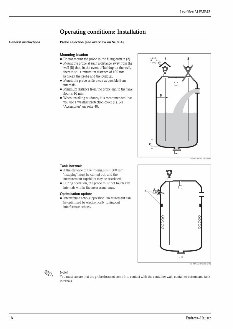
Operating conditions: Installation
General instructions Probe selection (see overview on Seite 4)
! Note!
You must ensure that the probe does not come into contact with the container wall, container bottom and tank
internals.
Mounting location
• Do not mount the probe in the filling curtain (2).
• Mount the probe at such a distance away from the
wall (B) that, in the event of buildup on the wall,
there is still a minimum distance of 100 mm
between the probe and the buildup.
• Mount the probe as far away as possible from
internals.
• Minimum distance from the probe end to the tank
floor is 10 mm.
• When installing outdoors, it is recommended that
you use a weather protection cover (1). See
"Accessories" on Seite 40.
L00-FMP43xxx-17-00-00-xx-001
B
1 2
C
Tank internals
• If the distance to the internals is < 300 mm,
"mapping" must be carried out, and the
measurement capability may be restricted.
• During operation, the probe must not touch any
internals within the measuring range.
Optimization options
• Interference echo suppression: measurement can
be optimized by electronically tuning out
interference echoes.
L00-FMP43xxx-17-00-00-xx-002
5

Levelflex M FMP43
Endress+Hauser 19
Cleaning of the probe Installation close to tank wall
Installation in the center of the tank
• By installing the probe close to the tank wall, the
cleaning effect is improved in cases where a spray
ball is used. The cleaning jet is deflected against the
tank wall and onto the probe. This means that
those parts of the probe are cleaned which would
normally not be reached by the spray ball jet. If the
probe is positioned in this way, only one spray ball
is needed.
L00-FMP43xxx-17-00-00-xx-003
• If the probe is mounted in the center of the tank, it
may be necessary to use a second spray ball. The
spray balls should then be mounted to the left and
right of the probe.
L00-FMP43xxx-17-00-00-xx-004
Levelflex M FMP43
20 Endress+Hauser
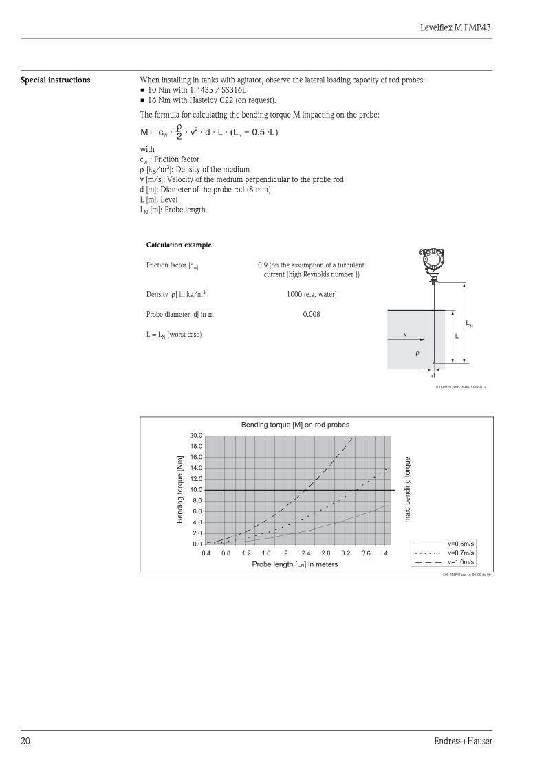
Special instructions When installing in tanks with agitator, observe the lateral loading capacity of rod probes:
• 10 Nm with 1.4435 / SS316L
• 16 Nm with Hasteloy C22 (on request).
The formula for calculating the bending torque M impacting on the probe:
with
cw : Friction factor
ρ [kg/m3]: Density of the medium
v [m/s]: Velocity of the medium perpendicular to the probe rod
d [m]: Diameter of the probe rod (8 mm)
L [m]: Level
LN [m]: Probe length
L00-FMP43xxx-16-00-00-de-004
Calculation example
L00-FMP43xxx-16-00-00-xx-003
Friction factor [cw] 0.9 (on the assumption of a turbulent
current (high Reynolds number ))
Density [ρ] in kg/m3 1000 (e.g. water)
Probe diameter [d] in m 0.008
L = LN (worst case)
M = c · · v · d · L · (L − 0.5 ·L)W N
2�
2
v
LN
L
d
Bending torque [M] on rod probes
Probe length [ ] in metersLN
v=0.5m/s
v=0.7m/s
v=1.0m/s
max.bendin
gto
rque
0.4 0.8 1.2 1.6 2 2.4 2.8 3.2 3.6 4
0.0
2.0
4.0
6.0
8.0
10.0
12.0
14.0
16.0
18.0
20.0
Bendin
g[N
m]
torq
ue
Levelflex M FMP43
Endress+Hauser 21
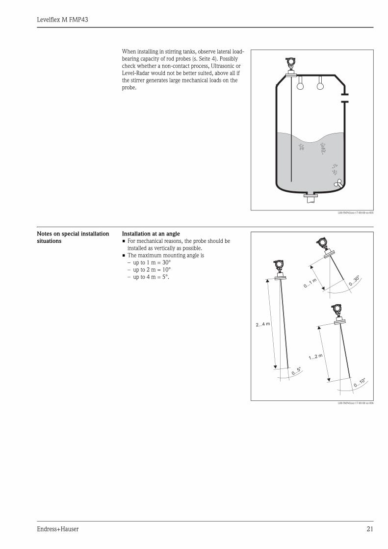
Notes on special installation
situations
When installing in stirring tanks, observe lateral load-
bearing capacity of rod probes (s. Seite 4). Possibly
check whether a non-contact process, Ultrasonic or
Level-Radar would not be better suited, above all if
the stirrer generates large mechanical loads on the
probe.
L00-FMP43xxx-17-00-00-xx-005
Installation at an angle
• For mechanical reasons, the probe should be
installed as vertically as possible.
• The maximum mounting angle is
– up to 1 m = 30°
– up to 2 m = 10°
– up to 4 m = 5°.
L00-FMP43xxx-17-00-00-xx-006
0...30°
0...10°
0...5°
0...1m
1...2 m
2...4 m
Levelflex M FMP43
22 Endress+Hauser
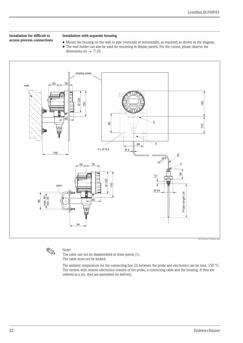
Installation for difficult to
access process connections
Installation with separate housing
• Mount the housing on the wall or pipe (vertically or horizontally, as required) as shown in the diagram.
• The wall holder can also be used for mounting in display panels. For the cutout, please observe the
dimensions on → ä 25.
L00-FMP43xxx-17-00-00-en-002
! Note!
The cable can not be disassembled at these points (1).
The cable must not be kinked.
The ambient temperature for the connecting line (2) between the probe and electronics can be max. 150 °C.
The version with remote electronics consists of the probe, a connecting cable and the housing. If they are
ordered as a set, they are assembled on delivery.
150
ENDRESS+HAUSERLevelflex M
65 78
Ø 1
29
85
150
ENDRESS+HAUSERLevelflex M
65 78
Ø 1
29
150
max
.80
min
. 30
96
146
94
88
88
123
1
4 x Ø 8,5
1
1
2
85
99
Ø 54
Ø 5
R
50≥
17
pipe
wall
display plate
Pro
be le
ngth
LN
Levelflex M FMP43
Endress+Hauser 23
Operating conditions: Environment
Ambient temperature range Ambient temperature for electronics: -40 °C to +80 °C
The functionality of the LCD display may be limited for temperatures Ta<-20 °C and Ta>+60 °C.
A weather protection cover should be used for outdoor operation if the instrument is exposed to direct sunlight.
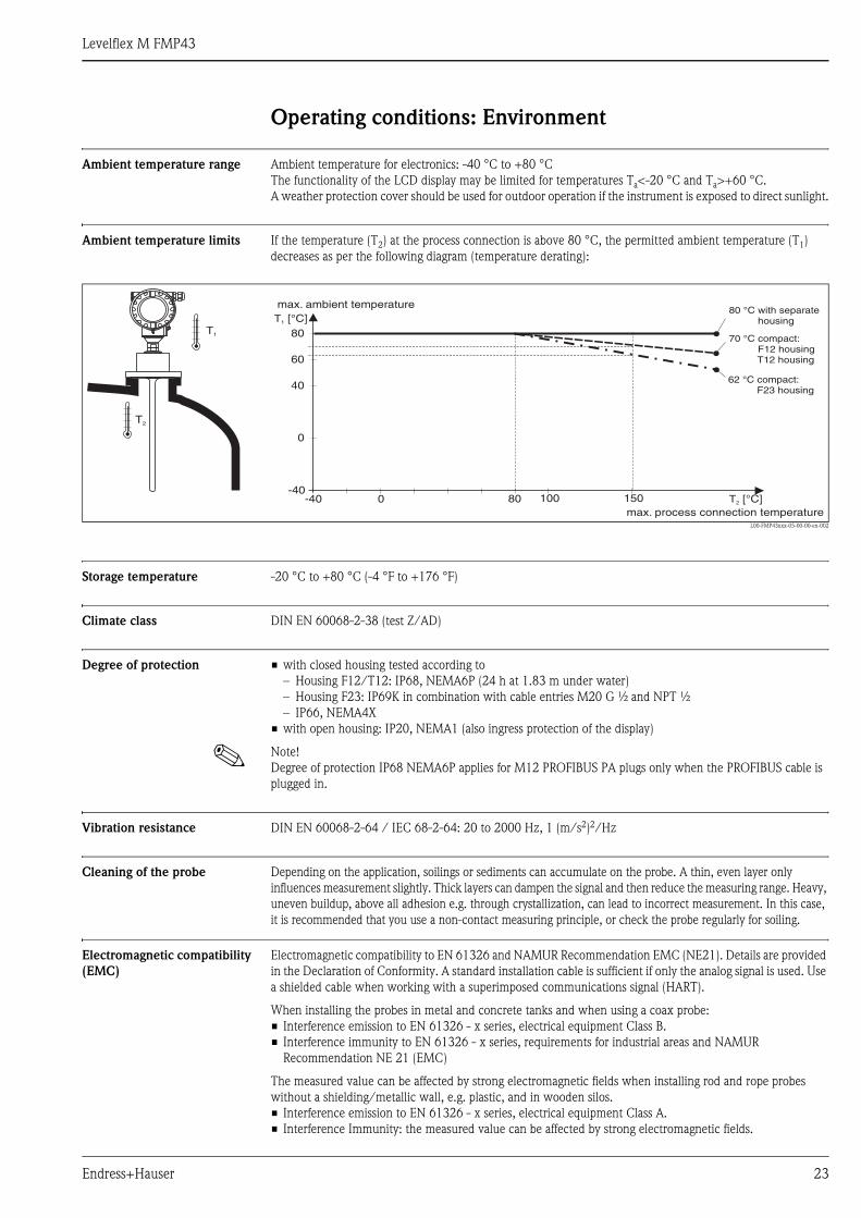
Ambient temperature limits If the temperature (T2) at the process connection is above 80 °C, the permitted ambient temperature (T1)
decreases as per the following diagram (temperature derating):
L00-FMP43xxx-05-00-00-en-002
Storage temperature -20 °C to +80 °C (-4 °F to +176 °F)
Climate class DIN EN 60068-2-38 (test Z/AD)
Degree of protection • with closed housing tested according to
– Housing F12/T12: IP68, NEMA6P (24 h at 1.83 m under water)
– Housing F23: IP69K in combination with cable entries M20 G ½ and NPT ½
– IP66, NEMA4X
• with open housing: IP20, NEMA1 (also ingress protection of the display)
! Note!
Degree of protection IP68 NEMA6P applies for M12 PROFIBUS PA plugs only when the PROFIBUS cable is
plugged in.
Vibration resistance DIN EN 60068-2-64 / IEC 68-2-64: 20 to 2000 Hz, 1 (m/s2)2/Hz
Cleaning of the probe Depending on the application, soilings or sediments can accumulate on the probe. A thin, even layer only
influences measurement slightly. Thick layers can dampen the signal and then reduce the measuring range. Heavy,
uneven buildup, above all adhesion e.g. through crystallization, can lead to incorrect measurement. In this case,
it is recommended that you use a non-contact measuring principle, or check the probe regularly for soiling.
Electromagnetic compatibility
(EMC)
Electromagnetic compatibility to EN 61326 and NAMUR Recommendation EMC (NE21). Details are provided
in the Declaration of Conformity. A standard installation cable is sufficient if only the analog signal is used. Use
a shielded cable when working with a superimposed communications signal (HART).
When installing the probes in metal and concrete tanks and when using a coax probe:
• Interference emission to EN 61326 - x series, electrical equipment Class B.
• Interference immunity to EN 61326 - x series, requirements for industrial areas and NAMUR
Recommendation NE 21 (EMC)
The measured value can be affected by strong electromagnetic fields when installing rod and rope probes
without a shielding/metallic wall, e.g. plastic, and in wooden silos.
• Interference emission to EN 61326 - x series, electrical equipment Class A.
• Interference Immunity: the measured value can be affected by strong electromagnetic fields.
T2 [°C]
T1 [°C]
-40 0-40
0
40
60
80 100 150
80
T2
T1
max. process connection temperature
max. ambient temperature80 °C with separate
housing
62 °C compact:F23 housing
70 °CF12 housingT12 housing
compact:
Levelflex M FMP43
24 Endress+Hauser
Operating conditions: Process
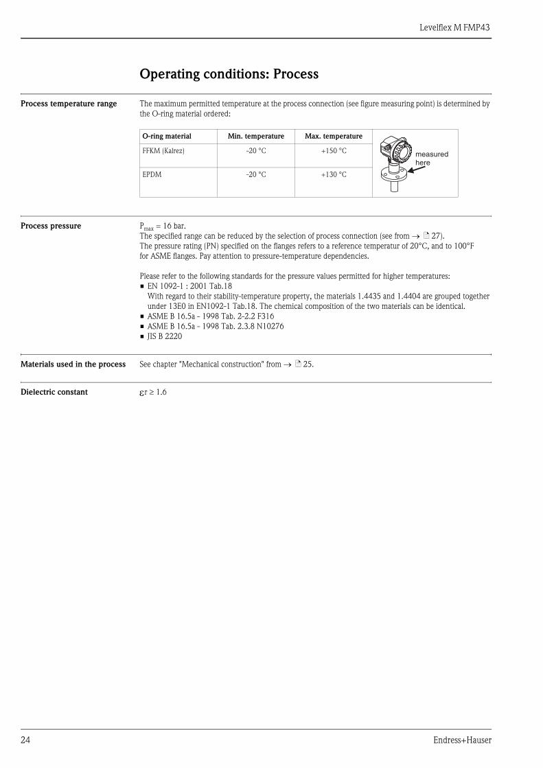
Process temperature range The maximum permitted temperature at the process connection (see figure measuring point) is determined by
the O-ring material ordered:
Process pressure Pmax = 16 bar.
The specified range can be reduced by the selection of process connection (see from → ä 27).
The pressure rating (PN) specified on the flanges refers to a reference temperatur of 20°C, and to 100°F
for ASME flanges. Pay attention to pressure-temperature dependencies.
Please refer to the following standards for the pressure values permitted for higher temperatures:
• EN 1092-1 : 2001 Tab.18
With regard to their stability-temperature property, the materials 1.4435 and 1.4404 are grouped together
under 13E0 in EN1092-1 Tab.18. The chemical composition of the two materials can be identical.
• ASME B 16.5a - 1998 Tab. 2-2.2 F316
• ASME B 16.5a - 1998 Tab. 2.3.8 N10276
• JIS B 2220
Materials used in the process See chapter "Mechanical construction" from → ä 25.
Dielectric constant εr ≥ 1.6
O-ring material Min. temperature Max. temperature
FFKM (Kalrez) -20 °C +150 °C
EPDM -20 °C +130 °C
measuredhere

Levelflex M FMP43
Endress+Hauser 25
Mechanical construction
Design, dimensions Housing (see Feature 80 in "Ordering information") - Dimensions and materials
Dimensions for process connection and type of probe s. Seite 26.
L00-F12xxxx-06-00-00-en-001
L00-T12xxxx-06-00-00-en-001
L00-F23xxxx-06-00-00-en-001
ENDRESS+HAUSER
65 78max. 110
85
150
Ø 1
29
(Aluminium)F12 housing
ENDRESS+HAUSER
78
85
65
162
max. 100 94
Ø 1
29
(Aluminium)T12 housing
max. 94 104
Ø 1
29
150
40
(316L)F23 housing
Levelflex M FMP43
26 Endress+Hauser
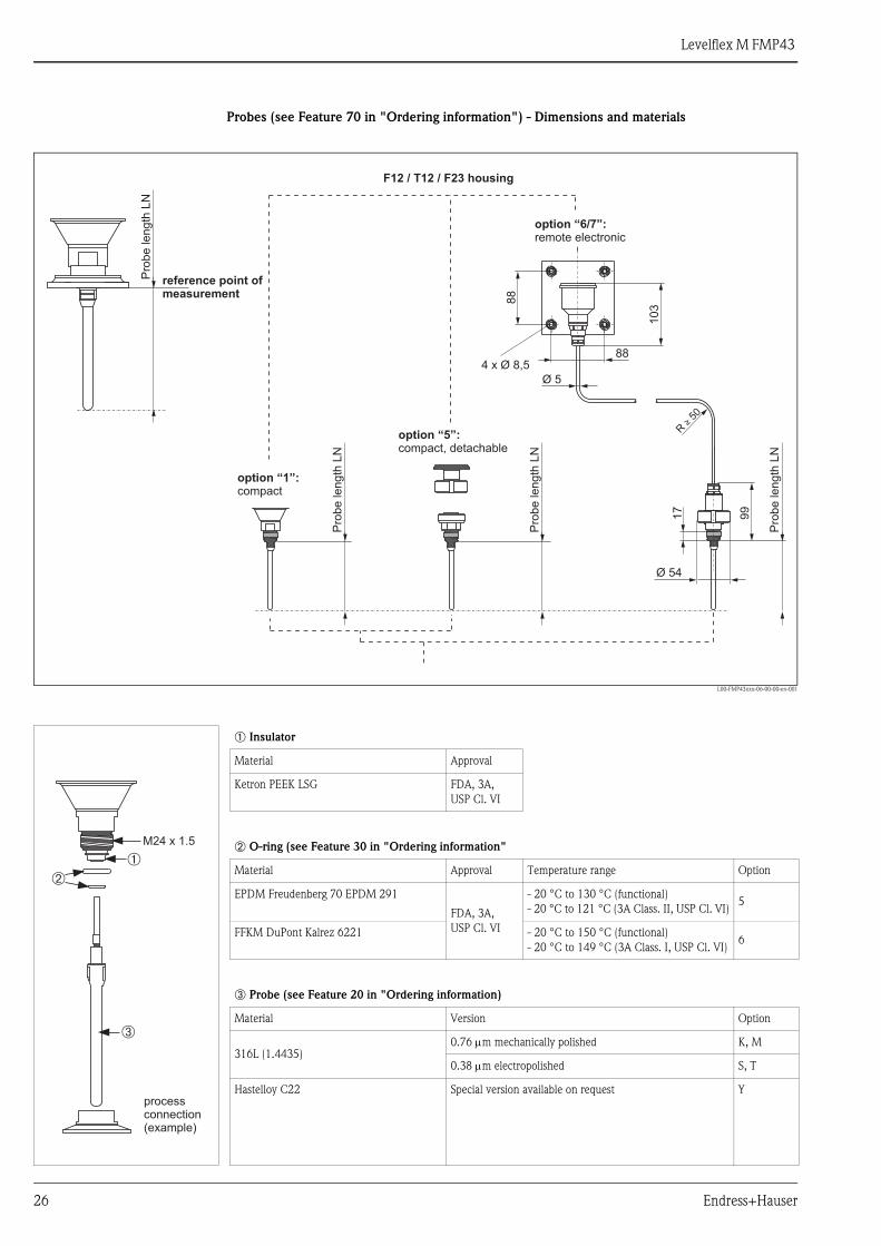
Probes (see Feature 70 in "Ordering information") - Dimensions and materials
L00-FMP43xxx-06-00-00-en-001
88
88
10
3
99
17
Ø 54
4 x Ø 8,5
R
50≥
Ø 5
F12 / T12 / F23 housing
option “6/7”:remote electronic
option “1”:compact
Pro
be
len
gth
LN
Pro
be
len
gth
LN
Pro
be
len
gth
LN
Pro
be
len
gth
LN
option “5”:compact, detachable
reference point ofmeasurement
➀ Insulator
Material Approval
Ketron PEEK LSG FDA, 3A,
USP Cl. VI
➁ O-ring (see Feature 30 in "Ordering information"
Material Approval Temperature range Option
EPDM Freudenberg 70 EPDM 291
FDA, 3A,
USP Cl. VI
- 20 °C to 130 °C (functional)
- 20 °C to 121 °C (3A Class. II, USP Cl. VI)5
FFKM DuPont Kalrez 6221 - 20 °C to 150 °C (functional)
- 20 °C to 149 °C (3A Class. I, USP Cl. VI)6
➂ Probe (see Feature 20 in "Ordering information)
Material Version Option
316L (1.4435) 0.76 μm mechanically polished K, M
0.38 μm electropolished S, T
Hastelloy C22 Special version available on request Y
➀➁
➂
processconnection(example)
M24 x 1.5

Levelflex M FMP43
Endress+Hauser 27
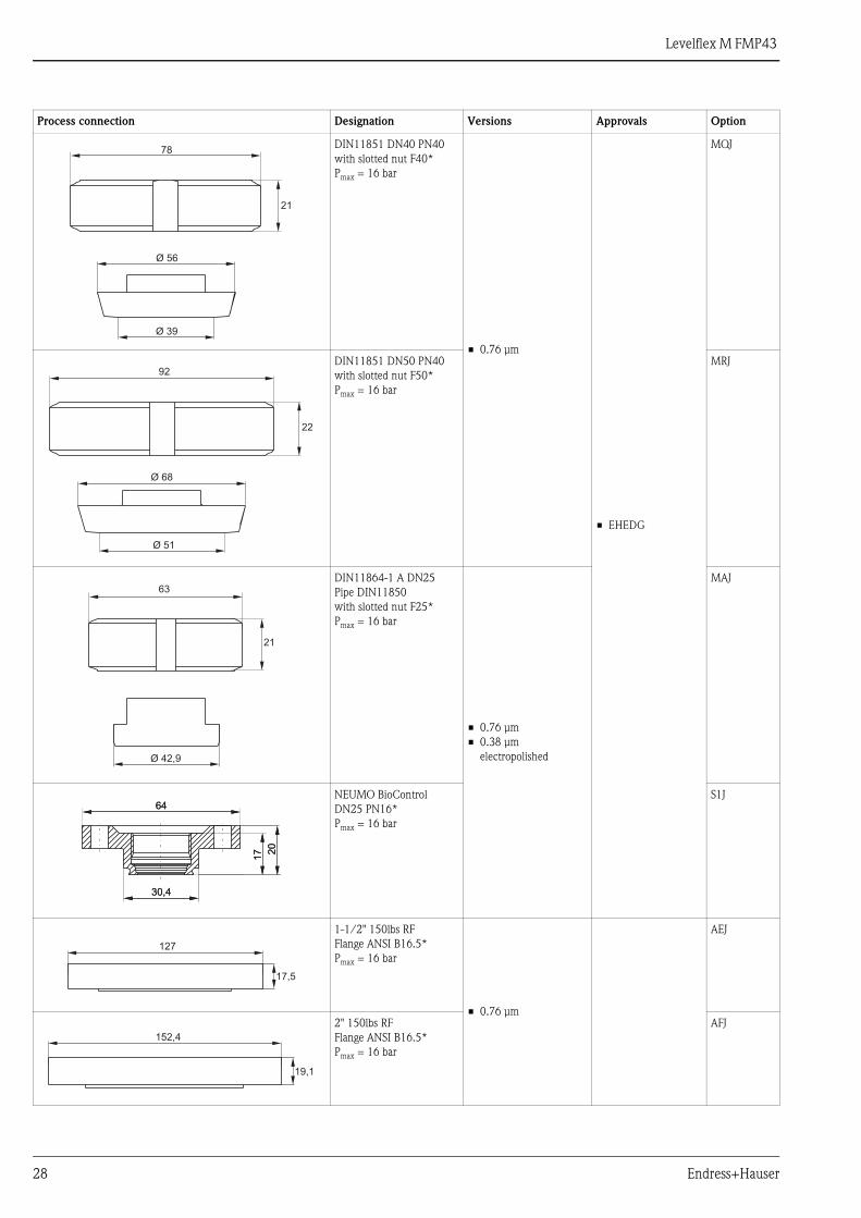
Process connections (see Feature 40 in "Ordering information") - Dimensions and materials
Endress+Hauser supplies DIN/EN flanges made of stainless steel AISI 316L with the material number 1.4435
or 1.4404. With regard to their stability-temperature property, the materials 1.4435 and 1.4404 are grouped
together under 13EO in EN 1092-1 Tab. 18. The chemical composition of the two materials can be identical.
Process connection Designation Versions Approvals Option
Tri-clamp ISO2852
DN25-38 (1 to 1-½")*
Pmax = 16 bar
• 0.76 μm
• 0.38 μm
electropolished
• 5 • EHEDG
• ASME-BPE
compliant
TCJ
Tri-clamp ISO2852
DN40-51 (2")*
Pmax = 16 bar
TDJ
Tri-clamp ISO2852
DN70-76.1 (3")
Pmax = 10 bar
TFJ
SMS 1-½" PN25
with slotted nut*
Pmax = 16 bar
• 0.76 μm • EHEDG
T7J
SMS 2" PN25
with slotted nut*
Pmax = 16 bar
TXJ
Ø 50,4
43,4
Ø 63,9
56,4
Ø 90,9
83,4
74
25
Ø 54,85
26
84
Ø 63,9
56,4
Levelflex M FMP43
28 Endress+Hauser
DIN11851 DN40 PN40
with slotted nut F40*
Pmax = 16 bar
• 0.76 μm
• EHEDG
MQJ
DIN11851 DN50 PN40
with slotted nut F50*
Pmax = 16 bar
MRJ
DIN11864-1 A DN25
Pipe DIN11850
with slotted nut F25*
Pmax = 16 bar
• 0.76 μm
• 0.38 μm
electropolished
MAJ
NEUMO BioControl
DN25 PN16*
Pmax = 16 bar
S1J
1-1/2" 150lbs RF
Flange ANSI B16.5*
Pmax = 16 bar
• 0.76 μm
AEJ
2" 150lbs RF
Flange ANSI B16.5*
Pmax = 16 bar
AFJ
Process connection Designation Versions Approvals Option
21
78
Ø 39
Ø 56
22
92
Ø 51
Ø 68
21
63
Ø 42,9
30,430,4
6464
17
17 2
020
127
17,5
152,4
19,1
Levelflex M FMP43
Endress+Hauser 29
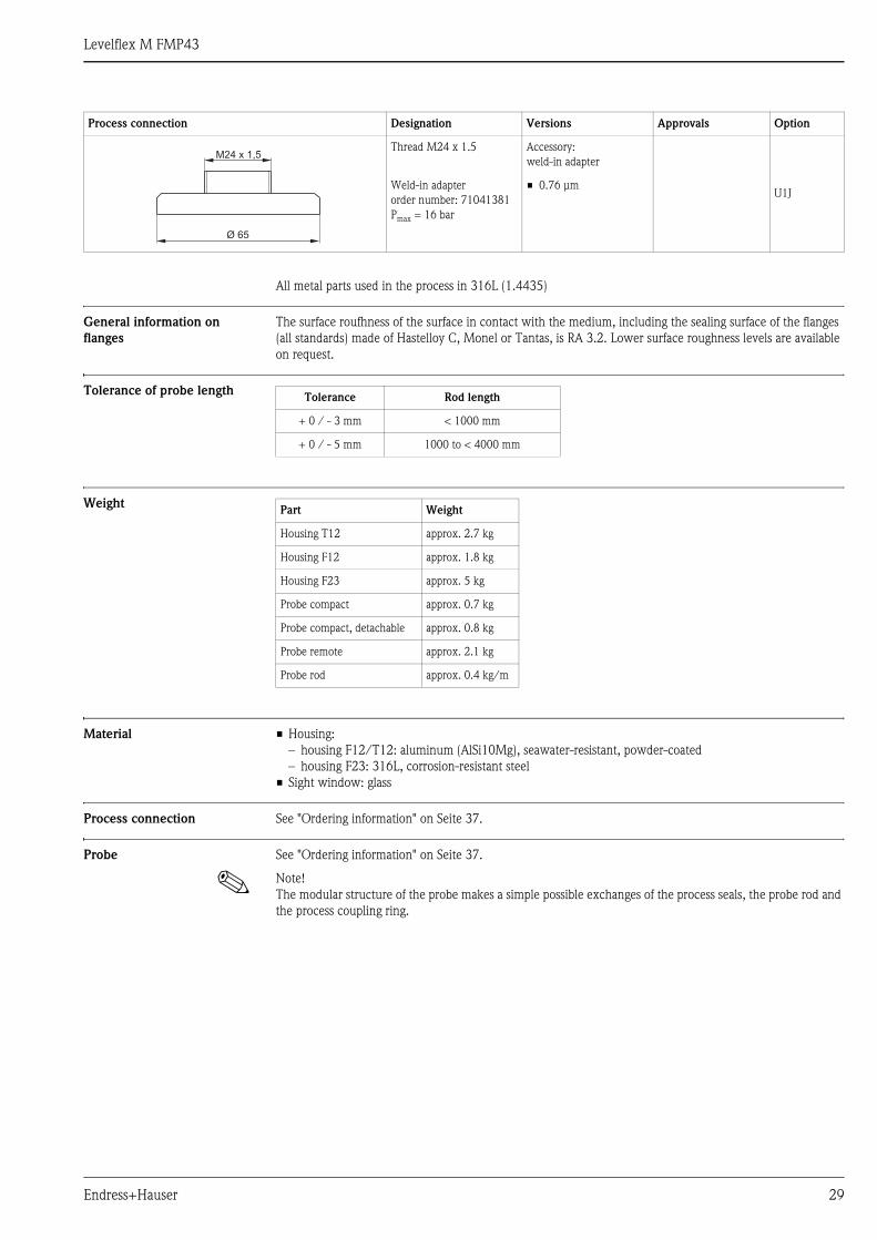
All metal parts used in the process in 316L (1.4435)
General information on
flanges
The surface roufhness of the surface in contact with the medium, including the sealing surface of the flanges
(all standards) made of Hastelloy C, Monel or Tantas, is RA 3.2. Lower surface roughness levels are available
on request.
Tolerance of probe length
Weight
Material • Housing:
– housing F12/T12: aluminum (AlSi10Mg), seawater-resistant, powder-coated
– housing F23: 316L, corrosion-resistant steel
• Sight window: glass
Process connection See "Ordering information" on Seite 37.
Probe See "Ordering information" on Seite 37.
! Note!
The modular structure of the probe makes a simple possible exchanges of the process seals, the probe rod and
the process coupling ring.
Thread M24 x 1.5 Accessory:
weld-in adapter
U1JWeld-in adapter
order number: 71041381
Pmax = 16 bar
• 0.76 μm
Process connection Designation Versions Approvals Option
Ø 65
M24 x 1,5
Tolerance Rod length
+ 0 / - 3 mm < 1000 mm
+ 0 / - 5 mm 1000 to < 4000 mm
Part Weight
Housing T12 approx. 2.7 kg
Housing F12 approx. 1.8 kg
Housing F23 approx. 5 kg
Probe compact approx. 0.7 kg
Probe compact, detachable approx. 0.8 kg
Probe remote approx. 2.1 kg
Probe rod approx. 0.4 kg/m

Levelflex M FMP43
30 Endress+Hauser
Human interface
Operation concept The display of the process value and the configuration of the Levelflex occur locally by means of a large 4-line
alphanumeric display with plain text information. The guided menu system with integrated help texts ensures
a quick and safe commissioning.
To access the display the cover of the electronic compartment may be removed even in hazardous area (IS and XP).
Remote commissioning, including documentation of the measuring point and in-depth analysis functions, is
supported via FieldCare, the graphical operating software for E+H time-of-flight systems.
Display elements Liquid crystal display (LCD):
Four lines with 20 characters each. Display contrast adjustable through key combination.
L00-FMxxxxxx-07-00-00-en-001
The VU331 LCD display can be removed to ease operation by simply pressing the snap-fit (see graphic above).
It is connected to the device by means of a 500 mm cable.
The following table describes the symbols that appear on the liquid crystal display:
ENDRESS + HAUSER
E+–
ENDRESS+HAUSER
MICROPILOT II
ENDRESS+HAUSER
MICROPILOT II
IP 65IP 65
Order Code:Ser.-No.:
Order Code:Ser.-No.:
MessbereichMeasuring range
MessbereichMeasuring rangeU 16...36 V DC
4...20 mA
U 16...36 V DC
4...20 mA
max. 20 m
max. 20 m
Made
inG
erm
any
Maulb
urg
Made
inG
erm
any
Maulb
urg
T>70°C :
A
t >85°C
T>70°C :
A
t >85°C
LCD(liquid crystal display)
Symbols
3 keys
snap-fit
Symbol Meaning
ALARM_SYMBOL
This alarm symbol appears when the instrument is in an alarm state. If the symbol flashes, this indicates a
warning.
LOCK_SYMBOL
This lock symbol appears when the instrument is locked,i.e. if no input is possible.
COM_SYMBOL
This communication symbol appears when a data transmission via e.g. HART, PROFIBUS PA or
FOUNDATION Fieldbus is in progress.
SIMULATION_SWITCH_ENABLE
This communication symbol appears when simulation in FOUNDATION Fieldbus is enabled via the DIP
switch.
Levelflex M FMP43
Endress+Hauser 31
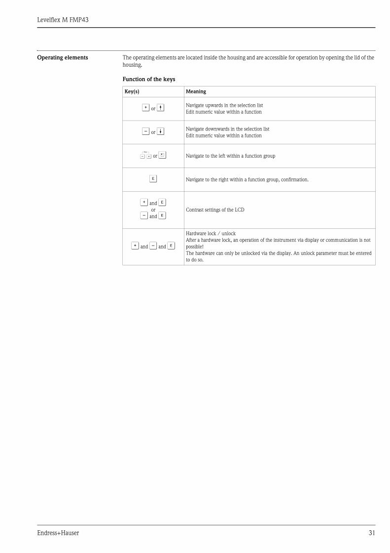
Operating elements The operating elements are located inside the housing and are accessible for operation by opening the lid of the
housing.
Function of the keys
Key(s) Meaning
O or V Navigate upwards in the selection list
Edit numeric value within a function
S or W Navigate downwards in the selection list
Edit numeric value within a function
X or Z Navigate to the left within a function group
F Navigate to the right within a function group, confirmation.
O and For
S and FContrast settings of the LCD
O and S and F
Hardware lock / unlock
After a hardware lock, an operation of the instrument via display or communication is not
possible!
The hardware can only be unlocked via the display. An unlock parameter must be entered
to do so.

Levelflex M FMP43
32 Endress+Hauser
Onsite operation Operation with VU331
The LC-Display VU331 allows configuration via 3 keys directly at the instrument. All device functions can be
set through a menu system. The menu consists of function groups and functions. Within a function, application
parameters can be read or adjusted. The user is guided through a complete configuration procedure.
L00-FMRxxxxx-07-00-00-en-002
Remote operation Operation with handheld unit Field Communicator 375
With the handheld terminal Field Communicator 375, you can configure all the device functions via menu
operation.
L00-FMPxxxxx-07-00-00-yy-005
! Note!
• Further information on the HART handheld unit is given in the respective operating manual included in the
transport bag of the Field Communicator 375.
XX
X
XS
S
OO FF
F
F
HOME
FG00 F000 F001 F002 F003 F004 ...
FG01FG02FG03FG04FG05FG06FG07
...
ENDRESS + HAUSER
E+–
Headline Position indicator
Main value UnitSymbol
Selection list
Function groups -> Functions
Help text
Envelopecurve
Bargraph
1# % &
Copy
G H I
P Q R S
, ( ) ‘
A B C
Paste
PageOn
PageUp
DeleteBksp
Insert
J K L
T U V
_ < >
D E F
Hot Key
+ Hot Key
M N O
W X Y Z
+ * /
4
7
.
2
5
8
0
375FIELD COMMUNICATOR
3
6
9
-
9 6
FMP40: LIC0001ONLINE
1 GROUP SELECT2 PV 8.7 m
HELP SAVE
dsdmdmdf das.asdas faasas la.
PageOn
PageUp
Bksp
Delete
Delete
FMP40: LIC0001ONLINE
1 GROUP SELECTION2 PV 8.7 m
HELP SAVE
dsdmdmdf das.asdas faasas la.
FMP40: LIC0001GROUP SELECTION
HOMESAVE
dsdmdmdf das.asdas faasas la.H
FMP40: LIC0001
HOMESAVE
dsdmdmdf das.asdas faasas la.H
Bksp
1 BASIC SETUP2 SAFETY SETTINGS
BASIC SETUP
1 MEASURED VALUE
4 PROCESS COND.
5 END OF PROBE
3 MEDIUM PROPERTY
4 LINEARISATION
5 EXTENDED CALIBR.
3 LENGTH ADJUSTMENT
2 TANK PROPERTIES

Levelflex M FMP43
Endress+Hauser 33
Remote operation The Levelflex M can be remotely operated via HART, PROFIBUS PA and FOUNDATION Fieldbus. Onsite
adjustments are also possible.
Operation with FieldCare
FieldCare is an Endress+Hauser Plant Asset Management Tool based on FDT technology. You can use Field-
Care to configure all your Endress+Hauser devices, as well as devices from other manufacturers that support
the FDT standard. It is compatible with the following operating systems: Win2000, WinXP and Windows Vista.
FieldCare supports the following functions:
• Online configuration of transmitters
• Signal analysis via envelope curve
• Tank linearization
• Loading and saving of device data (upload/download)
• Documentation of the measuring point
Connection options:
• HART via Commubox FXA191 and the RS 232 C serial port of a computer
• HART via Commubox FXA195 and the USB port of a computer
• PROFIBUS PA via segment coupler and PROFIBUS interface card
Menu-guided commissioning
Signal analysis via envelope curve
L00-fmp-Ixxx-20-00-00-en-033
L00-fmp-Ixxx-20-00-00-en-034

Levelflex M FMP43
34 Endress+Hauser
Operation with NI-FBUS Configurator (only FOUNDATION Fieldbus)
The NI-FBUS Configurator is an easy-to-use graphical environment for creating linkages, loops, and a schedule
based on the fieldbus concepts.
You can use the NI-FBUS Configurator to configure a fieldbus network as follows:
• Set block and device tags
• Set device addresses
• Create and edit function block control strategies (function block applications)
• Configure vendor-defined function and transducer blocks
• Create and edit schedules
• Read and write to function block control strategies (function block applications)
• Invoke Device Description (DD) methods
• Display DD menus
• Download a configuration
• Verify a configuration and compare it to a saved configuration
• Monitor a downloaded configuration
• Replace devices
• Save and print a configuration
L00-FMP4xxxx-20-00-00-de-011
Levelflex M FMP43
Endress+Hauser 35
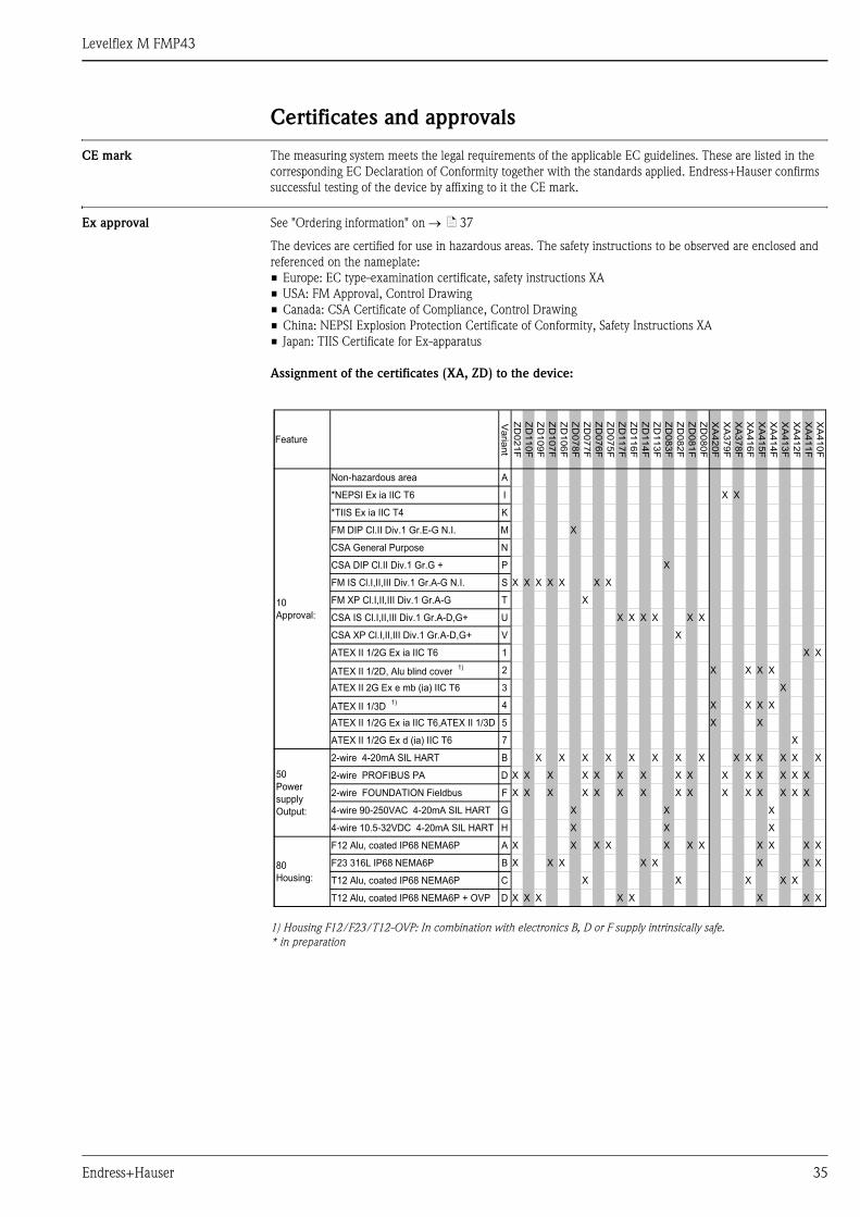
Certificates and approvals
CE mark The measuring system meets the legal requirements of the applicable EC guidelines. These are listed in the
corresponding EC Declaration of Conformity together with the standards applied. Endress+Hauser confirms
successful testing of the device by affixing to it the CE mark.
Ex approval See "Ordering information" on → ä 37
The devices are certified for use in hazardous areas. The safety instructions to be observed are enclosed and
referenced on the nameplate:
• Europe: EC type-examination certificate, safety instructions XA
• USA: FM Approval, Control Drawing
• Canada: CSA Certificate of Compliance, Control Drawing
• China: NEPSI Explosion Protection Certificate of Conformity, Safety Instructions XA
• Japan: TIIS Certificate for Ex-apparatus
Assignment of the certificates (XA, ZD) to the device:
1) Housing F12/F23/T12-OVP: In combination with electronics B, D or F supply intrinsically safe.
* in preparation
XA
41
0F
X
X
X
X
X
XA
41
1F
X
X
X
X
X
X
XA
41
2F
X
X
X
X
X
XA
41
3F
X
X
X
X
X
XA
41
4F
X
X
X
X
X
XA
41
5F
X
X
X
X
X
X
X
X
X
XA
41
6F
X
X
X
X
X
X
XA
37
8F
X
X
XA
37
9F
X
X
X
XA
42
0F
X
X
X
ZD
08
0F
X
X
X
ZD
08
1F
X
X
X
X
ZD
08
2F
X
X
X
X
X
ZD
08
3F
X
X
X
X
ZD
11
3F
X
X
X
ZD
11
4F
X
X
X
X
ZD
11
6F
X
X
X
ZD
11
7F
X
X
X
X
ZD
07
5F
X
X
X
ZD
07
6F
X
X
X
X
ZD
07
7F
X
X
X
X
X
ZD
07
8F
X
X
X
X
ZD
10
6F
X
X
X
ZD
10
7F
X
X
X
X
ZD
10
9F
X
X
X
ZD
11
0F
X
X
X
X
ZD
02
1F
X
X
X
X
X
X
Va
rian
t
A
I
K
M
N
P
S
T
U
V
1
2
3
4
5
7
B
D
F
G
H
A
B
C
D
Non-hazardous area
*NEPSI Ex ia IIC T6
*TIIS Ex ia IIC T4
FM DIP Cl.II Div.1 Gr.E-G N.I.
CSA General Purpose
CSA DIP Cl.II Div.1 Gr.G +
FM IS Cl.I,II,III Div.1 Gr.A-G N.I.
FM XP Cl.I,II,III Div.1 Gr.A-G
CSA IS Cl.I,II,III Div.1 Gr.A-D,G+
CSA XP Cl.I,II,III Div.1 Gr.A-D,G+
ATEX II 1/2G Ex ia IIC T6
ATEX II 1/2D, Alu blind cover 1)
ATEX II 2G Ex e mb (ia) IIC T6
ATEX II 1/3D 1)
ATEX II 1/2G Ex ia IIC T6,ATEX II 1/3D
ATEX II 1/2G Ex d (ia) IIC T6
2-wire 4-20mA SIL HART
2-wire PROFIBUS PA
2-wire FOUNDATION Fieldbus
4-wire 90-250VAC 4-20mA SIL HART
4-wire 10.5-32VDC 4-20mA SIL HART
F12 Alu, coated IP68 NEMA6P
F23 316L IP68 NEMA6P
T12 Alu, coated IP68 NEMA6P
T12 Alu, coated IP68 NEMA6P + OVP
Feature
10
Approval:
50
Power
supply
Output:
80
Housing:
Levelflex M FMP43
36 Endress+Hauser
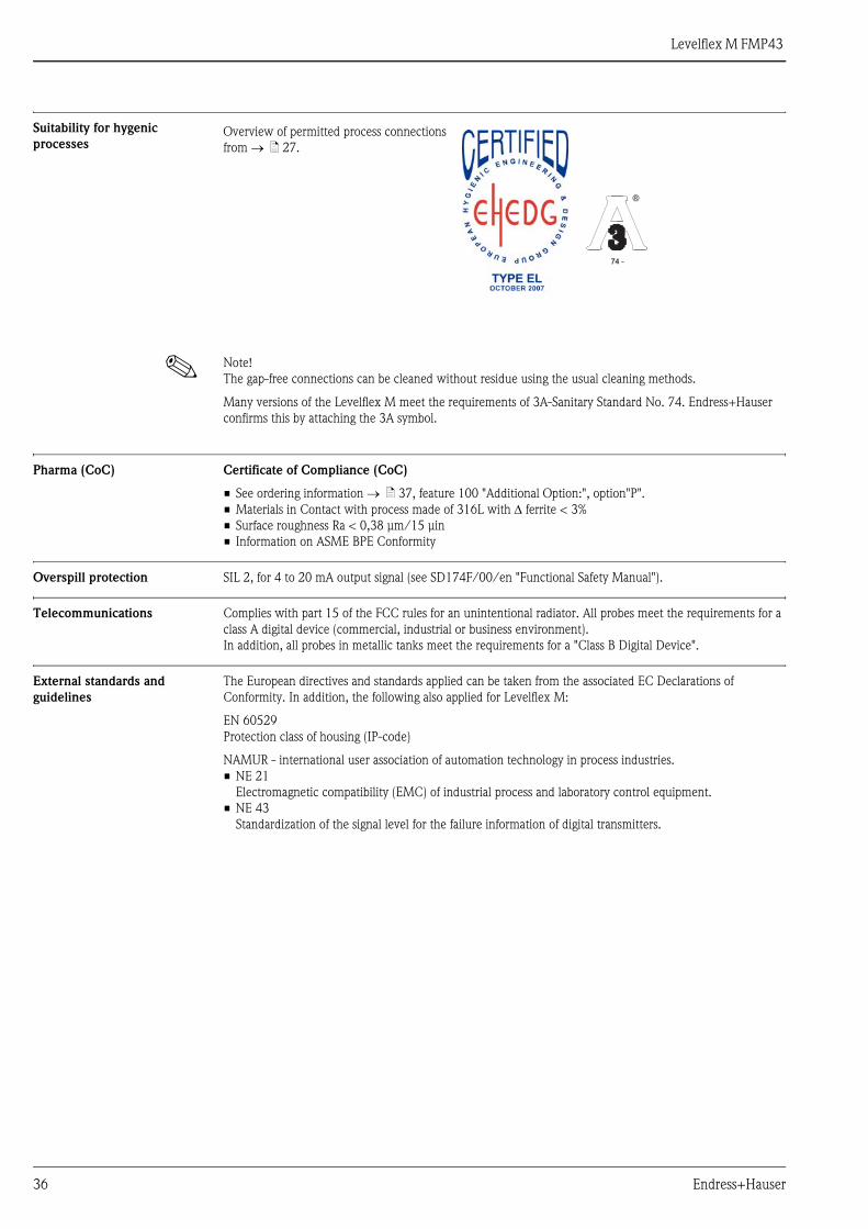
Suitability for hygenic
processes
! Note!
The gap-free connections can be cleaned without residue using the usual cleaning methods.
Many versions of the Levelflex M meet the requirements of 3A-Sanitary Standard No. 74. Endress+Hauser
confirms this by attaching the 3A symbol.
Pharma (CoC) Certificate of Compliance (CoC)
• See ordering information → ä 37, feature 100 "Additional Option:", option"P".
• Materials in Contact with process made of 316L with Δ ferrite < 3%
• Surface roughness Ra < 0,38 μm/15 μin
• Information on ASME BPE Conformity
Overspill protection SIL 2, for 4 to 20 mA output signal (see SD174F/00/en "Functional Safety Manual").
Telecommunications Complies with part 15 of the FCC rules for an unintentional radiator. All probes meet the requirements for a
class A digital device (commercial, industrial or business environment).
In addition, all probes in metallic tanks meet the requirements for a "Class B Digital Device".
External standards and
guidelines
The European directives and standards applied can be taken from the associated EC Declarations of
Conformity. In addition, the following also applied for Levelflex M:
EN 60529
Protection class of housing (IP-code)
NAMUR - international user association of automation technology in process industries.
• NE 21
Electromagnetic compatibility (EMC) of industrial process and laboratory control equipment.
• NE 43
Standardization of the signal level for the failure information of digital transmitters.
Overview of permitted process connections
from → ä 27.
74 -74 -
Levelflex M FMP43
Endress+Hauser 37
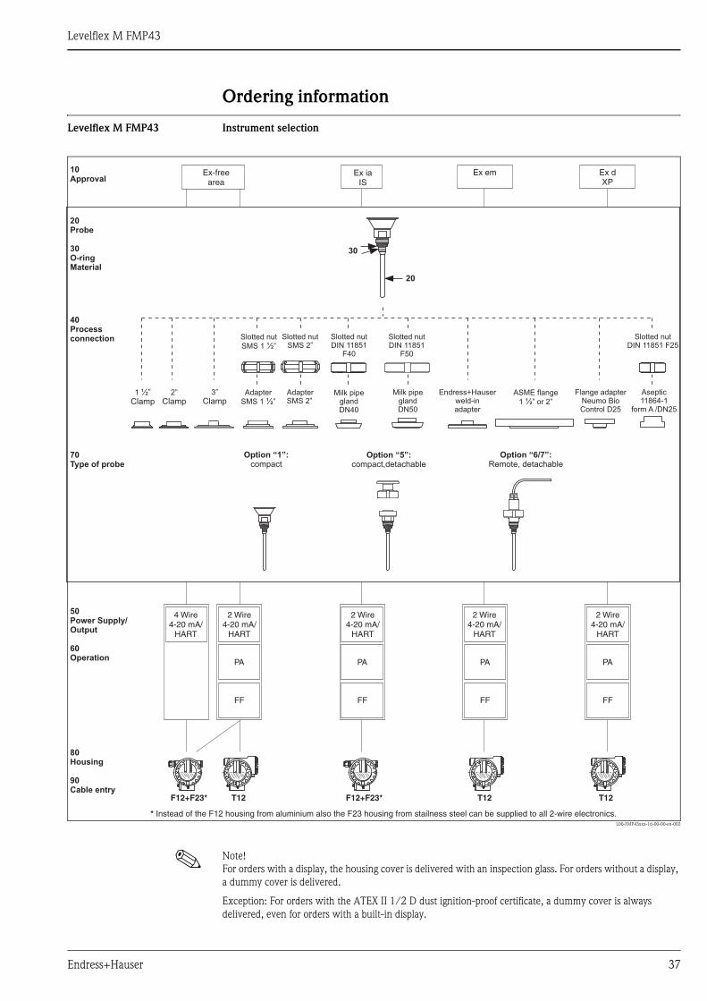
Ordering information
Levelflex M FMP43 Instrument selection
L00-FMP43xxx-16-00-00-en-002
! Note!
For orders with a display, the housing cover is delivered with an inspection glass. For orders without a display,
a dummy cover is delivered.
Exception: For orders with the ATEX II 1/2 D dust ignition-proof certificate, a dummy cover is always
delivered, even for orders with a built-in display.
F12+F23* F12+F23*T12 T12 T12
PA PA PA PA
FF FF FF FF
Ex em Ex dXP
1 ½”Clamp
2”
Clamp3”
Clamp
Ex iaIS
20
30
Ex-freearea
2 Wire4-20 mA/
HART
2 Wire4-20 mA/
HART
2 Wire4-20 mA/
HART
2 Wire4-20 mA/
HART
4 Wire4-20 mA/
HART
* Instead of the F12 housing from aluminium also the F23 housing from stailness steel can be supplied to all 2-wire electronics.
10Approval
40Processconnection
20Probe
30O-ringMaterial
50Power Supply/Output
60Operation
70Type of probe
80Housing
90Cable entry
Option “6/7”:Remote, detachable
Option “1”:compact
Option “5”:compact,detachable
Endress+Hauserweld-inadapter
AdapterSMS 2”
Adapter
SMS 1 ”½Milk pipe
glandDN50
Milk pipeglandDN40
Flange adapterNeumo BioControl D25
ASME flange
1 ½” or 2”
Slotted nutDIN 11851
F40
Slotted nutDIN 11851 F25
Slotted nutDIN 11851
F50
Slotted nutSMS 2”
Slotted nut
SMS 1 ”½
Aseptic11864-1
form A /DN25
Levelflex M FMP43
38 Endress+Hauser
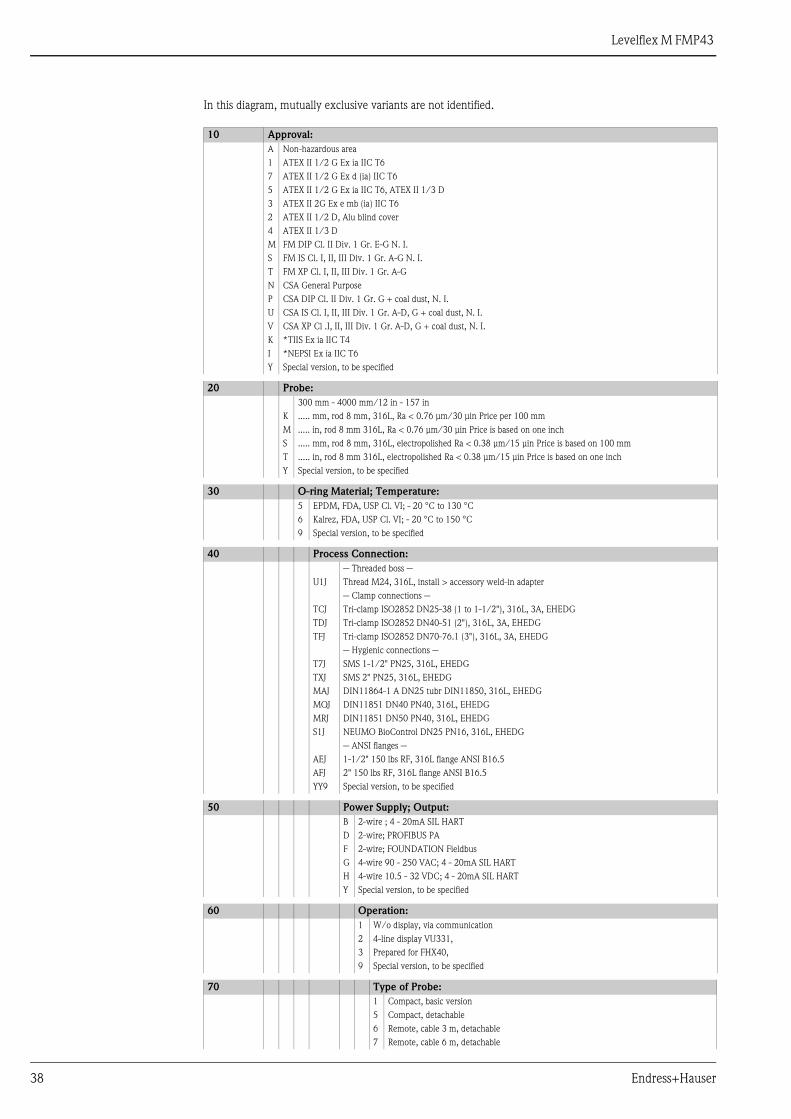
In this diagram, mutually exclusive variants are not identified.
10 Approval:
A Non-hazardous area
1 ATEX II 1/2 G Ex ia IIC T6
7 ATEX II 1/2 G Ex d (ia) IIC T6
5 ATEX II 1/2 G Ex ia IIC T6, ATEX II 1/3 D
3 ATEX II 2G Ex e mb (ia) IIC T6
2 ATEX II 1/2 D, Alu blind cover
4 ATEX II 1/3 D
M FM DIP Cl. II Div. 1 Gr. E-G N. I.
S FM IS Cl. I, II, III Div. 1 Gr. A-G N. I.
T FM XP Cl. I, II, III Div. 1 Gr. A-G
N CSA General Purpose
P CSA DIP Cl. II Div. 1 Gr. G + coal dust, N. I.
U CSA IS Cl. I, II, III Div. 1 Gr. A-D, G + coal dust, N. I.
V CSA XP Cl .I, II, III Div. 1 Gr. A-D, G + coal dust, N. I.
K *TIIS Ex ia IIC T4
I *NEPSI Ex ia IIC T6
Y Special version, to be specified
20 Probe:
300 mm - 4000 mm/12 in - 157 in
K ..... mm, rod 8 mm, 316L, Ra < 0.76 μm/30 μin Price per 100 mm
M ..... in, rod 8 mm 316L, Ra < 0.76 μm/30 μin Price is based on one inch
S ..... mm, rod 8 mm, 316L, electropolished Ra < 0.38 μm/15 μin Price is based on 100 mm
T ..... in, rod 8 mm 316L, electropolished Ra < 0.38 μm/15 μin Price is based on one inch
Y Special version, to be specified
30 O-ring Material; Temperature:
5 EPDM, FDA, USP Cl. VI; - 20 °C to 130 °C
6 Kalrez, FDA, USP Cl. VI; - 20 °C to 150 °C
9 Special version, to be specified
40 Process Connection:
-- Threaded boss --
U1J Thread M24, 316L, install > accessory weld-in adapter
-- Clamp connections --
TCJ Tri-clamp ISO2852 DN25-38 (1 to 1-1/2"), 316L, 3A, EHEDG
TDJ Tri-clamp ISO2852 DN40-51 (2"), 316L, 3A, EHEDG
TFJ Tri-clamp ISO2852 DN70-76.1 (3"), 316L, 3A, EHEDG
-- Hygienic connections --
T7J SMS 1-1/2" PN25, 316L, EHEDG
TXJ SMS 2" PN25, 316L, EHEDG
MAJ DIN11864-1 A DN25 tubr DIN11850, 316L, EHEDG
MQJ DIN11851 DN40 PN40, 316L, EHEDG
MRJ DIN11851 DN50 PN40, 316L, EHEDG
S1J NEUMO BioControl DN25 PN16, 316L, EHEDG
-- ANSI flanges --
AEJ 1-1/2" 150 lbs RF, 316L flange ANSI B16.5
AFJ 2" 150 lbs RF, 316L flange ANSI B16.5
YY9 Special version, to be specified
50 Power Supply; Output:
B 2-wire ; 4 - 20mA SIL HART
D 2-wire; PROFIBUS PA
F 2-wire; FOUNDATION Fieldbus
G 4-wire 90 - 250 VAC; 4 - 20mA SIL HART
H 4-wire 10.5 - 32 VDC; 4 - 20mA SIL HART
Y Special version, to be specified
60 Operation:
1 W/o display, via communication
2 4-line display VU331,
3 Prepared for FHX40,
9 Special version, to be specified
70 Type of Probe:
1 Compact, basic version
5 Compact, detachable
6 Remote, cable 3 m, detachable
7 Remote, cable 6 m, detachable
Levelflex M FMP43
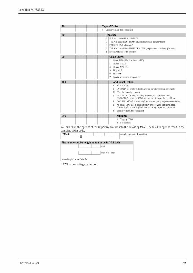
Endress+Hauser 39
You can fill in the options of the respective feature into the following table. The filled in options result in the
complete order code.
1) OVP = overvoltage protection
9 Special version, to be specified
80 Housing:
A F12 Alu, coated IP68 NEMA 6P
C T12 Alu, coated IP68 NEMA 6P, separate conn. compartment
B F23 316L IP68 NEMA 6P
D T12 Alu, coated IP68 NEMA 6P + OVP1), seperate terminal compartment
Y Special version, to be specified
90 Cable Entry:
2 Gland M20 (EEx d > thread M20)
3 Thread G 1/2
4 Thread NPT 1/2
5 Plug M12
6 Plug 7/8"
9 Special version, to be specified
100 Additional Option:
A Basic version
B EN 10204-3.1 material (316L wetted parts) inspection certificate
H *5-point linearity protocol
J *5-point, 3.1, 5-point linearity protocol, see additional spec.,
EN10204-3.1 material (316L wetted parts), inspection certificate
P CoC, EN 10204-3.1 material (316L wetted parts) inspection certificate
R *5-point, CoC, 3.1, 5-point linearity protocol, see additional spec.,
EN10204-3.1 material (316L wetted parts), inspection certificate
Y Special version, to be specified
995 Marking:
1 Tagging (TAG)
2 Bus address
FMP43- complete product designation
⇓Please enter probe length in mm or inch / 0.1 inch
mm
inch / 0.1 inch
probe lenght LN → Seite 26
70 Type of Probe:

Levelflex M FMP43
40 Endress+Hauser
Accessories
Weather protection cover A weather protection cover made of stainless steel is recommended for outdoor mounting (order code:
543199-0001). The shipment includes the protective cover and tension clamp.
L00-FMR2xxxx-00-00-06-en-001
Weld-in adapter
ENDRESS+HAUSER
MICROPILOT II
ENDRESS+HAUSER
MICROPILOT II
IP 65IP 65
Order Code:Ser.-No.:
Order Code:Ser.-No.:
MessbereichMeasuring range
MessbereichMeasuring rangeU 16...36 V DC
4...20 mA
U 16...36 V DC4...20 mA
max. 20 m
max. 20 m
Ma
de
in G
erm
any
Ma
ulb
urg
Ma
de
in G
erm
any
Ma
ulb
urg
T>70°C :
A
t >85°C
T>70°C :
A
t >85°C
70 m
m
240 mm 135 mm
95m
m45°F12 / T12 housing
Welding adapter with M 24 x of 1.5 - threads for the
front-concise assembly of the sensor.
Material: corrosion-resistant steel
1.4435 (AISI 316L)
Weight: 0.22 kg
For details refer to BA361F/00/A6.
• Standard
Order No.: 71041381
• With 3.1 inspection certificate
Order No.: 71041383
L00-FMP43xxx-06-00-00-xx-016
Ø 65
M24 x 1,5

Levelflex M FMP43
Endress+Hauser 41
Remote display and operation
FHX40
L00-FMxxxxxx-00-00-06-de-005
Technical data (cable and housing) and product structure:
For connection of the remote display FHX40 use the cable which fits the communication version of the
respective instrument.
ENDRESS+HAUSER
ENDRESS+HAUSER
IP 65IP 65
Order Code:Ser.-No.:
Order Code:Ser.-No.:
MessbereichMeasuring range
MessbereichMeasuring range U 16...36V DC
4...20 mA
U 16...36V DC4...20 mA
max.20 m
max.20 m
Made in Germany Maulburg
Made in Germany Maulburg
T>70°C :
A
t >85°C
T>70°C :
A
t >85°C
82
6,3
106
122
120
88
160
8,5
180
max. 80min. 30
96118
Micropilot MLevelflex MProsonic M
122
150
80
Separate housingFHX40 (IP 65)
Cable
Wall-mounting(without mounting bracket)
Pipe-mounting(mounting bracket and plate
supplied optionally, s. product structure)
pipe
Separate housing
FHX40 (IP 65)
Max. cable length 20 m (65 ft)
Temperature range -30 °C...+70 °C (-22 °F...158 °F)
Degree of protection IP65/67(housing); IP68 (cable) acc. to IEC 60529
Materials Housing: AlSi12; cable glands: nickle plated brass
Dimensions [mm] / [inch] 122x150x80 (HxWxD) / 4.8x5.9x3.2
Approval:
A Non-hazardous area
C NEPSI Ex ia IIC T6/T5
G IECEx Zone1 Ex ia IIC T6/T5
K TIIS Ex ia IIC T6
N CSA General Purpose
S FM IS Cl. I Div.1 Gr. A-D
U CSA IS Cl. I Div.1 Gr. A-D
1 ATEX II 2G Ex ia IIC T6, ATEX II 3D
Y Special version, to be specified
Cable:
1 20m / 65ft (> for HART)
5 20m / 65ft (> for PROFIBUS PA/FOUNDATION Fieldbus)
9 Special version, to be specified
Additional option:
A Basic version
B Mounting bracket, pipe 1"/ 2"
Y Special version, to be specified
Marking:
1 Tagging (TAG)
FHX40 - Complete product designation
Levelflex M FMP43
42 Endress+Hauser
Commubox FXA191 HART For intrinsically safe communication with FieldCare via the RS232C interface. For details refer to
TI237F/00/en.
Commubox FXA195 HART For intrinsically safe communication with FieldCare via the USB interface. For details refer to TI404F/00/en.
Commubox FXA291 The Commubox FXA291 connects Endress+Hauser field instruments with CDI interface (= Endress+Hauser
Common Data Interface) to the USB interface of a personal computer or a notebook. For details refer to
TI405C/07/en.
! Note!
For the following Endress+Hauser instruments you need the "ToF Adapter FXA291" as an additional accessory:
• Cerabar S PMC71, PMP7x
• Deltabar S PMD7x, FMD7x
• Deltapilot S FMB70
• Gammapilot M FMG60
• Levelflex M FMP4x
• Micropilot FMR130/FMR131
• Micropilot M FMR2xx
• Micropilot S FMR53x, FMR540
• Prosonic FMU860/861/862
• Prosonic M FMU4x
• Tank Side Monitor NRF590 (with additional adapter cable)
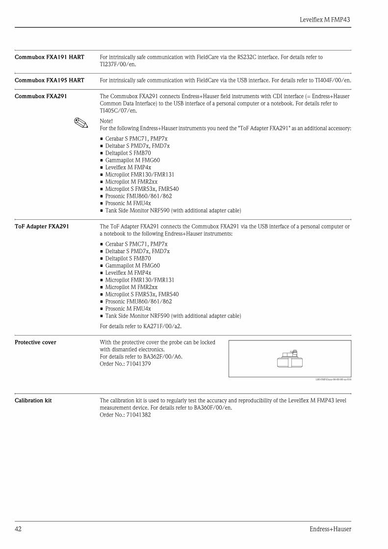
ToF Adapter FXA291 The ToF Adapter FXA291 connects the Commubox FXA291 via the USB interface of a personal computer or
a notebook to the following Endress+Hauser instruments:
• Cerabar S PMC71, PMP7x
• Deltabar S PMD7x, FMD7x
• Deltapilot S FMB70
• Gammapilot M FMG60
• Levelflex M FMP4x
• Micropilot FMR130/FMR131
• Micropilot M FMR2xx
• Micropilot S FMR53x, FMR540
• Prosonic FMU860/861/862
• Prosonic M FMU4x
• Tank Side Monitor NRF590 (with additional adapter cable)
For details refer to KA271F/00/a2.
Protective cover
Calibration kit The calibration kit is used to regularly test the accuracy and reproducibility of the Levelflex M FMP43 level
measurement device. For details refer to BA360F/00/en.
Order No.: 71041382
With the protective cover the probe can be locked
with dismantled electronics.
For details refer to BA362F/00/A6.
Order No.: 71041379
L00-FMP43xxx-06-00-00-xx-016

Levelflex M FMP43
Endress+Hauser 43
Additional documentationThis Additional documentation can be found on our product pages on "www.endress.com".
Fields of activities Level measurement
Level limit detection and continuous level measurement in liquids and bulk solids,
FA001F/00/en.
Competence brochure Continuous Level Measurement in Liquids
Selection and engineering for the process industrie, CP023F/00/en.
Technical Information Fieldgate FXA520
Technical Information for Fieldgate FXA520, TI369F/00/en.
Operating Instructions Levelflex M
Correlation of operating instructions to the instrument:
Engineering hints PROFIBUS PA
Guidelines for planning and commissioning, BA198F/00.
Patents This product may be protected by at least one of the following listed patents.
Further patents are pending.
• US 5,661,251 i EP 0 780 664
• US 5,827,985 i EP 0 780 664
• US 5,884,231 i EP 0 780 665
• US 5,973,637 i EP 0 928 974
Device
typeOutput 1
1) assignment, see ordering information: 50 electronic insert/communication
CommunicationOperating
Instructions
Description of
device functions
Brief
Operating
Instructions
(in device)
FMP43 B, G, H HART BA357F/00/en BA245F/00/en KA189F/00/a2
D PROFIBUS PA BA358F/00/en BA245F/00/en KA189F/00/a2
F FOUNDATION Fieldbus BA359F/00/en BA245F/00/en KA189F/00/a2
Levelflex M FMP43
Instruments International
Endress+HauserInstruments International AGKaegenstrasse 24153 ReinachSwitzerland
Tel. +41 61 715 81 00Fax +41 61 715 25 [email protected]
TI424F/00/en/03.09
No. 71074951
FM+SGML 6.0 ProMoDo71074951