lg hűtő
DESCRIPTION
User manual for LG refrigerators, type: GR-L247FTTRANSCRIPT

CAUTIONPLEASE READ CAREFULLY THE SAFETY PRECAUTIONS OF THIS BOOK BEFORE CHECKING OR OPERATING THE REFRIGERATOR.
REFRIGERATORSERVICE MANUAL
MODEL: GR-L247FT/FVBA COLOR: SUPER WHITE TITANIUM
http://biz.lgservice.com

WARNINGS AND PRECAUTIONS FOR SAFETY ................................................................................................................ 3
SPECIFICATIONS................................................................................................................................................................... 4
PARTS IDENTIFICATION ..................................................................................................................................................... 12
HOW TO INSTALL THE REFRIGERATOR .......................................................................................................................... 18
HOW TO ADJUST DOOR HEIGHT OF THE REFRIGERATOR ........................................................................................ 18
HOW TO INSTALL WATER PIPE........................................................................................................................................19
HOW TO CONTROL THE AMOUNT OF WATER SUPPLIED TO THE ICEMAKER ......................................................... 23
MICOM FUNCTION .............................................................................................................................................................. 25
EXPLATION FOR MICOM CIRCUIT..................................................................................................................................... 34
EXPLANATION FOR PWB CIRCUIT ..................................................................................................................................34
COMPENSATION CIRCUIT FOR WEAK-COLD, OVER-COLD AT FREEZING ROOM.....................................................48
PWB PARTS DRAWING AND LIST ....................................................................................................................................52
PWB CIRCUIT DIAGRAM ...................................................................................................................................................62
ICE MAKER AND DISPENSER OPERATION PRINCIPLE AND REPAIR METHOD.......................................................... 66
WORKING PRINCIPLES.....................................................................................................................................................66
FUNCTION OF ICE MAKER ...............................................................................................................................................67
ICE MAKER TROUBLESHOOTING....................................................................................................................................70
ICE MAKER CIRCUIT PART...............................................................................................................................................71
CIRCUIT................................................................................................................................................................................ 72
TROUBLE DIAGNOSIS........................................................................................................................................................ 74
TROUBLE SHOOTING ...................................................................................................................................................... 74
FAULTS .............................................................................................................................................................................. 84
COOLING CYCLE HEAVY REPAIR................................................................................................................................. 101
HOW TO DEAL WITH CLAIMS........................................................................................................................................ 108
HOW TO DISASSEMBLE AND ASSEMBLE ..................................................................................................................... 113
DOOR ............................................................................................................................................................................... 113
HANDLE ........................................................................................................................................................................... 114
SHROUD, GRILLE FAN ................................................................................................................................................... 114
ICEMAKER ....................................................................................................................................................................... 114
DISPENSER ..................................................................................................................................................................... 115
WATER TANK AND WATER LINE.................................................................................................................................... 117
HOME BAR....................................................................................................................................................................... 117
EXPLODED VIEW............................................................................................................................................................... 118
REPLACEMENT PARTS LIST ........................................................................................................................................... 127
CONTENTS
- 2 -

Please observe the following safety precautions in order touse safely and correctly the refrigerator and to preventaccident and danger during repair.
1. Be care of an electric shock. Disconnect power cordfrom wall outlet and wait for more than three minutesbefore replacing PWB parts. Shut off the powerwhenever replacing and repairing electric components.
2. When connecting power cord, please wait for more thanfive minutes after power cord was disconnected from thewall outlet.
3. Please check if the power plug is pressed down by therefrigerator against the wall. If the power plug wasdamaged, it may cause fire or electric shock.
4. If the wall outlet is over loaded, it may cause fire. Pleaseuse its own individual electrical outlet for the refrigerator.
5. Please make sure the outlet is properly earthed,particularly in wet or damp area.
6. Use standard electrical components when replacingthem.
7. Make sure the hook is correctly engaged. Remove dust and foreign materials from the housingand connecting parts.
8. Do not fray, damage, machine, heavily bend, pull out,or twist the power cord.
9. Please check the evidence of moisture intrusion in theelectrical components. Replace the parts or mask itwith insulation tapes if moisture intrusion wasconfirmed.
10. Do not touch the icemaker with hands or tools toconfirm the operation of geared motor.
11. Do not let the customers repair, disassemble, andreconstruct the refrigerator for themselves. It maycause accident, electric shock, or fire.
12. Do not store flammable materials such as ether,benzene, alcohol, chemicals, gas, or medicine in therefrigerator.
13. Do not put flower vase, cup, cosmetics, chemicals,etc., or container with full of water on the top of therefrigerator.
14. Do not put glass bottles with full of water into thefreezer. The contents shall freeze and break the glassbottles.
15. When you scrap the refrigerator, please disconnect thedoor gasket first and scrap it where children are notaccessible.
WARNINGS AND PRECAUTIONS FOR SAFETY
- 3 -

SPECIFICATIONS
- 4 -
ITEMS SPECIFICATIONS
DIMENSIONS (mm) 890(W)X845(D)X1750(H)
NET WEIGHT (kg) 128
COOLING SYSTEM Fan Cooling
TEMPERATURE CONTROL Micom Control
DEFROSTING SYSTEM Full Automatic
Heater Defrost
INSULATION Cyclo-Pentane
COMPRESSOR P.T.C. Starting Type
EVAPORATOR Fin Tube Type
CONDENSER Wire Condenser
REFRIGERANT R134a (180g)
LUBRICATING OIL FREOL @10G (310 cc)
DRIER 1Ø0.83
CAPILLARY TUBE MOLECULAR SIEVE XH-7
ITEMS SPECIFICATIONS
FIRST DEFROST 4 - 5 Hours
DEFROST CYCLE 13 - 15 Hours
DEFROSTING DEVICE Heater, Sheath
ANTI SWEAT HEATER Dispenser Duct Door Heater
Dispenser Heater
Home Bar Heater
ANTI-FREEZING HEATER Damper Heater
FREEZER LAMP 40W (1 EA)
REFRIGERATOR LAMP 40W (1 EA)
DISPENSER LAMP 15W (1 EA)
1750
1720
1750
687
948
890
747
796
845
1220
.5
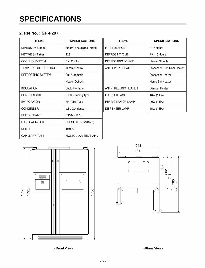
<Front View> <Plane View>
1. Ref No. : GR-P247
SPECIFICATIONS
- 5 -
ITEMS SPECIFICATIONS
DIMENSIONS (mm) 890(W)X760(D)X1750(H)
NET WEIGHT (kg) 123
COOLING SYSTEM Fan Cooling
TEMPERATURE CONTROL Micom Control
DEFROSTING SYSTEM Full Automatic
Heater Defrost
INSULATION Cyclo-Pentane
COMPRESSOR P.T.C. Starting Type
EVAPORATOR Fin Tube Type
CONDENSER Wire Condenser
REFRIGERANT R134a (180g)
LUBRICATING OIL FREOL @10G (310 cc)
DRIER 1Ø0.83
CAPILLARY TUBE MOLECULAR SIEVE XH-7
1750
1720
1750
602
948
890
662
711
760
1135
.5
<Front View> <Plane View>
2. Ref No. : GR-P207
ITEMS SPECIFICATIONS
FIRST DEFROST 4 - 5 Hours
DEFROST CYCLE 13 - 15 Hours
DEFROSTING DEVICE Heater, Sheath
ANTI SWEAT HEATER Dispenser Duct Door Heater
Dispenser Heater
Home Bar Heater
ANTI-FREEZING HEATER Damper Heater
FREEZER LAMP 40W (1 EA)
REFRIGERATOR LAMP 40W (1 EA)
DISPENSER LAMP 15W (1 EA)

SPECIFICATIONS
- 6 -
ITEMS SPECIFICATIONS
DIMENSIONS (mm) 890(W)X845(D)X1750(H)
NET WEIGHT (kg) 125
COOLING SYSTEM Fan Cooling
TEMPERATURE CONTROL Micom Control
DEFROSTING SYSTEM Full Automatic
Heater Defrost
INSULATION Cyclo-Pentane
COMPRESSOR P.T.C. Starting Type
EVAPORATOR Fin Tube Type
CONDENSER Wire Condenser
REFRIGERANT R134a (180g)
LUBRICATING OIL FREOL @10G (310 cc)
DRIER 1Ø0.83
ITEMS SPECIFICATIONS
CAPILLARY TUBE MOLECULAR SIEVE XH-7
FIRST DEFROST 4 - 5 Hours
DEFROST CYCLE 13 - 15 Hours
DEFROSTING DEVICE Heater, Sheath
ANTI SWEAT HEATER Dispenser Duct Door Heater
Dispenser Heater
ANTI-FREEZING HEATER Damper Heater
FREEZER LAMP 40W (1 EA)
REFRIGERATOR LAMP 40W (1 EA)
DISPENSER LAMP 15W (1 EA)
1750
1720
1750
687
948
890
747
796
845
1220
.5
<Front View> <Plane View>
3. Ref No. : GR-L247

SPECIFICATIONS
- 7 -
ITEMS SPECIFICATIONS
DIMENSIONS (mm) 890(W)X760(D)X1750(H)
NET WEIGHT (kg) 120
COOLING SYSTEM Fan Cooling
TEMPERATURE CONTROL Micom Control
DEFROSTING SYSTEM Full Automatic
Heater Defrost
INSULATION Cyclo-Pentane
COMPRESSOR P.T.C. Starting Type
EVAPORATOR Fin Tube Type
CONDENSER Wire Condenser
REFRIGERANT R134a (180g)
LUBRICATING OIL FREOL @10G (310 cc)
DRIER 1Ø0.83
1750
1720
1750
602
948
890
662
711
760
1135
.5
<Front View> <Plane View>
4. Ref No. : GR-L207
ITEMS SPECIFICATIONS
CAPILLARY TUBE MOLECULAR SIEVE XH-7
FIRST DEFROST 4 - 5 Hours
DEFROST CYCLE 13 - 15 Hours
DEFROSTING DEVICE Heater, Sheath
ANTI SWEAT HEATER Dispenser Duct Door Heater
Dispenser Heater
ANTI-FREEZING HEATER Damper Heater
FREEZER LAMP 40W (1 EA)
REFRIGERATOR LAMP 40W (1 EA)
DISPENSER LAMP 15W (1 EA)

SPECIFICATIONS
- 8 -
ITEMS SPECIFICATIONS
DIMENSIONS (mm) 890(W)X845(D)X1750(H)
NET WEIGHT (kg) 117
COOLING SYSTEM Fan Cooling
TEMPERATURE CONTROL Micom Control
DEFROSTING SYSTEM Full Automatic
Heater Defrost
INSULATION Cyclo-Pentane
COMPRESSOR P.T.C. Starting Type
EVAPORATOR Fin Tube Type
CONDENSER Wire Condenser
REFRIGERANT R134a (180g)
LUBRICATING OIL FREOL @10G (310 cc)
DRIER 1Ø0.83
CAPILLARY TUBE MOLECULAR SIEVE XH-7
ITEMS SPECIFICATIONS
FIRST DEFROST 4 - 5 Hours
DEFROST CYCLE 13 - 15 Hours
DEFROSTING DEVICE Heater, Sheath
ANTI SWEAT HEATER Home Bar Heater
ANTI-FREEZING HEATER Damper Heater
FREEZER LAMP 40W (1 EA)
REFRIGERATOR LAMP 40W (1 EA)
DISPENSER LAMP 15W (1 EA)
1750
1720
1750
687
948
890
747
796
845
1220
.5
<Front View> <Plane View>
1. Ref No. : GR-C247
SPECIFICATIONS
- 9 -
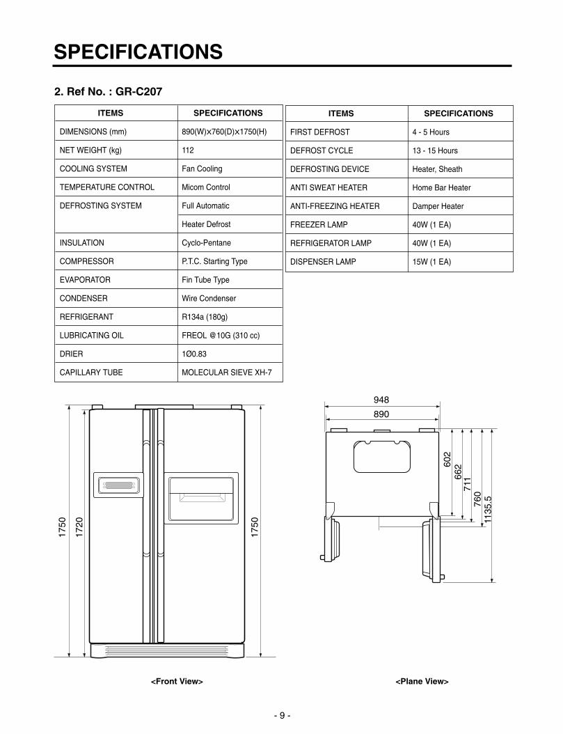
ITEMS SPECIFICATIONS
DIMENSIONS (mm) 890(W)X760(D)X1750(H)
NET WEIGHT (kg) 112
COOLING SYSTEM Fan Cooling
TEMPERATURE CONTROL Micom Control
DEFROSTING SYSTEM Full Automatic
Heater Defrost
INSULATION Cyclo-Pentane
COMPRESSOR P.T.C. Starting Type
EVAPORATOR Fin Tube Type
CONDENSER Wire Condenser
REFRIGERANT R134a (180g)
LUBRICATING OIL FREOL @10G (310 cc)
DRIER 1Ø0.83
CAPILLARY TUBE MOLECULAR SIEVE XH-7
1750
1720
1750
602
948
890
662
711
760
1135
.5
<Front View> <Plane View>
2. Ref No. : GR-C207
ITEMS SPECIFICATIONS
FIRST DEFROST 4 - 5 Hours
DEFROST CYCLE 13 - 15 Hours
DEFROSTING DEVICE Heater, Sheath
ANTI SWEAT HEATER Home Bar Heater
ANTI-FREEZING HEATER Damper Heater
FREEZER LAMP 40W (1 EA)
REFRIGERATOR LAMP 40W (1 EA)
DISPENSER LAMP 15W (1 EA)

SPECIFICATIONS
- 10 -
ITEMS SPECIFICATIONS
DIMENSIONS (mm) 890(W)X845(D)X1750(H)
NET WEIGHT (kg) 114
COOLING SYSTEM Fan Cooling
TEMPERATURE CONTROL Micom Control
DEFROSTING SYSTEM Full Automatic
Heater Defrost
INSULATION Cyclo-Pentane
COMPRESSOR P.T.C. Starting Type
EVAPORATOR Fin Tube Type
CONDENSER Wire Condenser
REFRIGERANT R134a (180g)
LUBRICATING OIL FREOL @10G (310 cc)
DRIER 1Ø0.83
ITEMS SPECIFICATIONS
CAPILLARY TUBE MOLECULAR SIEVE XH-7
FIRST DEFROST 4 - 5 Hours
DEFROST CYCLE 13 - 15 Hours
DEFROSTING DEVICE Heater, Sheath
ANTI-FREEZING HEATER Damper Heater
FREEZER LAMP 40W (1 EA)
REFRIGERATOR LAMP 40W (1 EA)
DISPENSER LAMP 15W (1 EA)
1750
1720
1750
687
948
890
747
796
845
1220
.5
<Front View> <Plane View>
3. Ref No. : GR-B247

SPECIFICATIONS
- 11 -
ITEMS SPECIFICATIONS
DIMENSIONS (mm) 890(W)X760(D)X1750(H)
NET WEIGHT (kg) 109
COOLING SYSTEM Fan Cooling
TEMPERATURE CONTROL Micom Control
DEFROSTING SYSTEM Full Automatic
Heater Defrost
INSULATION Cyclo-Pentane
COMPRESSOR P.T.C. Starting Type
EVAPORATOR Fin Tube Type
CONDENSER Wire Condenser
REFRIGERANT R134a (180g)
LUBRICATING OIL FREOL @10G (310 cc)
DRIER 1Ø0.83
ITEMS SPECIFICATIONS
CAPILLARY TUBE MOLECULAR SIEVE XH-7
FIRST DEFROST 4 - 5 Hours
DEFROST CYCLE 13 - 15 Hours
DEFROSTING DEVICE Heater, Sheath
ANTI-FREEZING HEATER Damper Heater
FREEZER LAMP 40W (1 EA)
REFRIGERATOR LAMP 40W (1 EA)
DISPENSER LAMP 15W (1 EA)
1750
1720
1750
602
948
890
662
711
760
1135
.5
<Front View> <Plane View>
4. Ref No. : GR-B207

PARTS IDENTIFICATION
- 12 -
Select
Meat
Cheese
Veg.
Home Bar
Frame Display
Dispenser Lamp
Ice & WaterDispenser Button
Conversion Switch(Meats/Vegetables)
Humidity Switch
Freezer Compartment
Refrigerator Compartment
Cover Hinge Cover PWB
Cover, Lamp-R/U
Shelf
Egg Box
Snack Corner
Vegetable Box
Adjust Screw
Basket
Cover Home Bar
Cover Lamp-R/L
Shelf
Guide Bottle
Wine Rack
BackHandle
Water Tube
Cover,Lamp -F
Shelf -F
Drawer
Cover Lower
Adjust Screw
Cover, Dairy
Ice Bank Assy
Ice Shelf Assy
Door Rack
1. Ref No. : GR-P247, GR-P207

2. Ref No. : GR-P247, GR-P207
PARTS IDENTIFICATION
- 13 -
Home Bar
Frame Display
Dispenser Lamp
Ice & WaterDispenser Button
Cover Hinge Cover PWB
BackHandle
Select
Meat
Cheese
Veg.
Conversion Switch(Meats/Vegetables)
Humidity Switch
Freezer Compartment
Refrigerator Compartment
Cover, Lamp-R/U
Shelf
Egg Box
Snack Corner
Vegetable Box
Adjust Screw
Basket
Cover Home Bar
Cover Lamp-R/L
Shelf
Guide Bottle
Wine Rack
Shelf -F
Drawer
Cover Lower
Adjust Screw
Cover, Dairy
Cover,Lamp -F
Ice Bank Assy
Ice Shelf Assy
Door Rack
PARTS IDENTIFICATION
- 14 -
Select
Meat
Cheese
Veg.
Humidity Switch
Freezer Compartment
Refrigerator Compartment
Conversion Switch(Meats/Vegetables)
Cover, Lamp-R/U
Shelf
Egg Box
Snack Corner
Vegetable Box
Adjust Screw
Basket
Cover Lamp-R/L
Shelf
Guide Bottle
Wine Rack
Shelf -F
Drawer
Cover Lower
Adjust Screw
Cover, Dairy
Frame Display
Dispenser Lamp
Ice & WaterDispenser Button
Cover Hinge Cover PWB
BackHandle
Water Tube
Cover,Lamp -F
Ice Bank Assy
Ice Shelf Assy
Door Rack
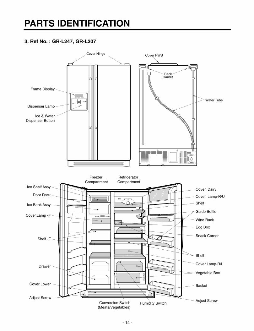
3. Ref No. : GR-L247, GR-L207
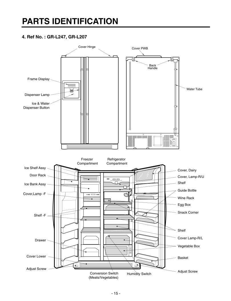
4. Ref No. : GR-L247, GR-L207
PARTS IDENTIFICATION
- 15 -
Frame Display
Dispenser Lamp
Ice & WaterDispenser Button
Cover Hinge Cover PWB
BackHandle
Water Tube
Select
Meat
Cheese
Veg.
Humidity Switch
Freezer Compartment
Refrigerator Compartment
Conversion Switch(Meats/Vegetables)
Cover, Lamp-R/U
Shelf
Egg Box
Snack Corner
Vegetable Box
Adjust Screw
Basket
Cover Lamp-R/L
Shelf
Guide Bottle
Wine Rack
Shelf -F
Drawer
Cover Lower
Adjust Screw
Cover, Dairy
Cover,Lamp -F
Ice Bank Assy
Ice Shelf Assy
Door Rack

PARTS IDENTIFICATION
- 16 -
Cover PWB
Cover, Lamp-R/U
Shelf
Egg Box
Snack Corner
Vegetable Box
Adjust Screw
Basket
Cover Home Bar
Shelf
Cover, Lamp-R/L
Guide Bottle
Wine Rack
BackHandle
Shelf -F
Drawer
Cover Lower
Adjust Screw
Cover, Dairy
Ice Bank Assy
Control Box,R
Cover Hinge
Home Bar
Conversion Switch(Meats/Vegetables)
Humidity Switch
Freezer Compartment
Refrigerator Compartment
Frame Display
1. Ref No. : GR-C247, GR-C207

PARTS IDENTIFICATION
- 17 -
Cover PWB
Cover, Lamp-R/U
Shelf
Egg Box
Snack Corner
Vegetable Box
Adjust Screw
Basket
Shelf
Cover, Lamp-R/L
Guide Bottle
Wine Rack
BackHandle
Shelf -F
Drawer
Cover Lower
Adjust Screw
Cover, Dairy
Ice Bank Assy
Control Box,R
Cover Hinge
Conversion Switch(Meats/Vegetables)
Humidity Switch
Freezer Compartment
Refrigerator Compartment
Frame Display
3. Ref No. : GR-B247, GR-B207

1. How to Adjust Door Height of Refrigerator Make the refrigerator level first. (If the refrigerator is not installed on the flat floor, the height of freezer and refrigerator
door may not be the same.)
1. If the height of freezer door is lower than that ofrefrigerator compartment :
2. If the height of freezer door is higher than that ofrefrigerator compartment :
Insert a driver into the groove of adjusting screwand rotate driver in arrow direction (clockwise) until therefrigerator becomes horizontal.
Insert a driver into the groove of adjusting screwand rotate driver in arrow direction (clockwise) until therefrigerator becomes horizontal.
HOW TO INSTALL REFRIGERATOR
- 18 -
AdjustingScrew
Driver
Height Difference
Height Difference
Height Difference
Height Difference
1
2
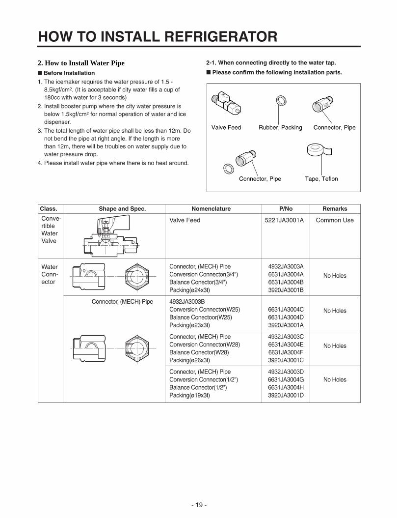
2. How to Install Water Pipe Before Installation
1. The icemaker requires the water pressure of 1.5 -8.5kgf/cm2. (It is acceptable if city water fills a cup of 180cc with water for 3 seconds)
2. Install booster pump where the city water pressure is below 1.5kgf/cm2 for normal operation of water and ice dispenser.
3. The total length of water pipe shall be less than 12m. Donot bend the pipe at right angle. If the length is morethan 12m, there will be troubles on water supply due to water pressure drop.
4. Please install water pipe where there is no heat around.
2-1. When connecting directly to the water tap.
Please confirm the following installation parts.
HOW TO INSTALL REFRIGERATOR
- 19 -
Class. Shape and Spec. Nomenclature P/No Remarks
Valve Feed 5221JA3001A Common Use
Connector, (MECH) Pipe 4932JA3003AConversion Connector(3/4") 6631JA3004A No HolesBalance Conector(3/4") 6631JA3004BPacking(ø24x3t) 3920JA3001B
Connector, (MECH) Pipe 4932JA3003BConversion Connector(W25) 6631JA3004C No HolesBalance Conectoor(W25) 6631JA3004DPacking(ø23x3t) 3920JA3001A
Connector, (MECH) Pipe 4932JA3003CConversion Connector(W28) 6631JA3004E No HolesBalance Conector(W28) 6631JA3004FPacking(ø26x3t) 3920JA3001C
Connector, (MECH) Pipe 4932JA3003DConversion Connector(1/2") 6631JA3004G No HolesBalance Conector(1/2") 6631JA3004HPacking(ø19x3t) 3920JA3001D
Conve-rtibleWaterValve
WaterConn-ector
Valve Feed Rubber, Packing Connector, Pipe
Tape, TeflonConnector, Pipe

1. Connection of Pipe Connector A and B.
1) Turn off main valve of water pipe.
2) Disconnect water tap from piping by loosening nuts.
3) Connect pipe connector A and B to piping after sealingthe pipe connector with sealing tapes.
4) Connect feed valve to pipe connector A.
5) If there is only one tap water pipe, connect pipe connector A only and install feed pipe.
2. Water Supply
1) After the installation of feed water, plug the refrigerator to the earthered wall outlet, press the water dispenserbutton for 2 - 3 minutes, and confirm that the watercomes out.
Caution : • Feed pipe should be connected to cold water line. If it is connected to hot water line, trouble may occur.
• Please check rubber packing when connecting feed pipe.
2) Check leakage at connecting part, then arrange watertube and locate the refrigerator at its regular place ifthere is no leaking.
HOW TO INSTALL REFRIGERATOR
- 20 -
Single Lever Type Faucet(general)
FeedValve
General Type
FeedValve
Two Hands Type Faucet Single Lever Type Faucet (onehole, tech type and hand spray)
FeedValve
FeedValve
Pipe Connector B
Hot WaterPipe Connector A
FeedValve
Cold Water
How to windSealing Tapes.
Water Tube
Water Tube
Nut
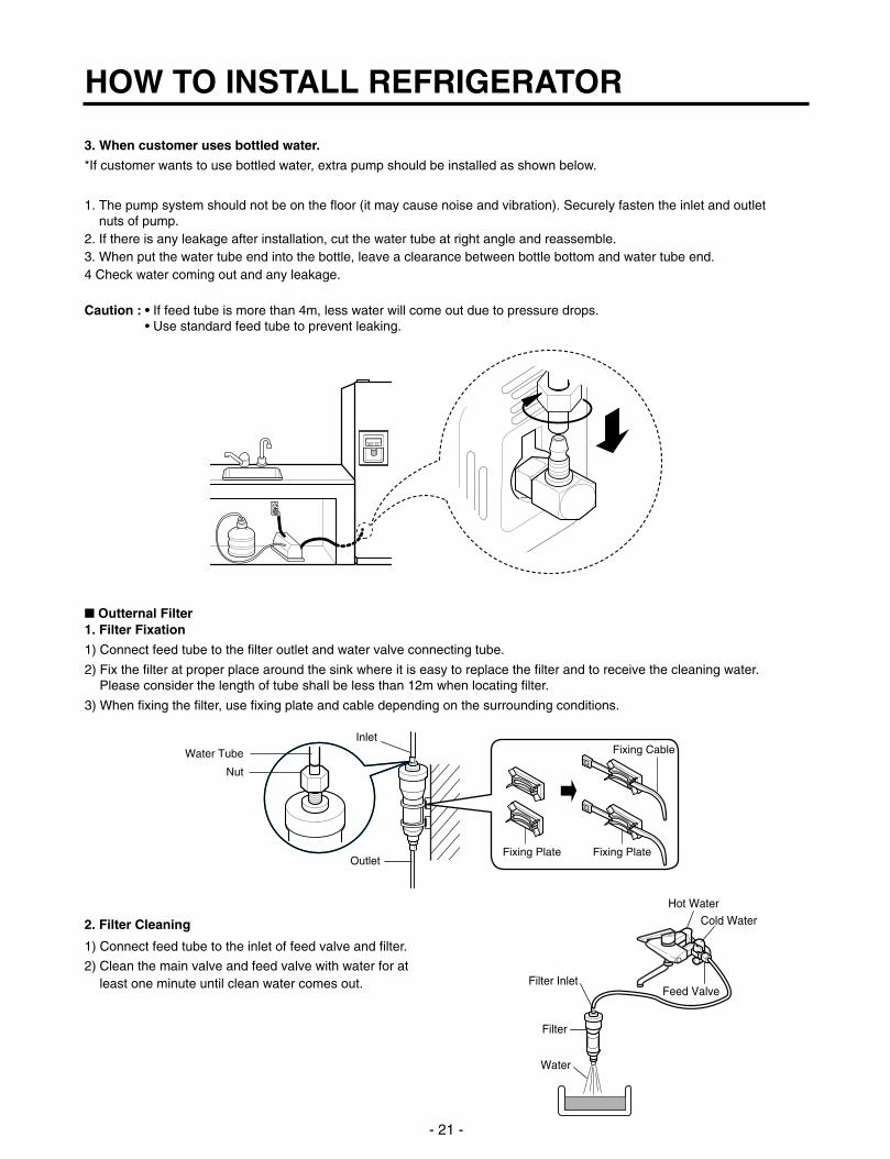
3. When customer uses bottled water.
*If customer wants to use bottled water, extra pump should be installed as shown below.
1. The pump system should not be on the floor (it may cause noise and vibration). Securely fasten the inlet and outletnuts of pump.
2. If there is any leakage after installation, cut the water tube at right angle and reassemble.3. When put the water tube end into the bottle, leave a clearance between bottle bottom and water tube end.4 Check water coming out and any leakage.
Caution : • If feed tube is more than 4m, less water will come out due to pressure drops.• Use standard feed tube to prevent leaking.
Outternal Filter1. Filter Fixation
1) Connect feed tube to the filter outlet and water valve connecting tube.
2) Fix the filter at proper place around the sink where it is easy to replace the filter and to receive the cleaning water. Please consider the length of tube shall be less than 12m when locating filter.
3) When fixing the filter, use fixing plate and cable depending on the surrounding conditions.
2. Filter Cleaning
1) Connect feed tube to the inlet of feed valve and filter.
2) Clean the main valve and feed valve with water for atleast one minute until clean water comes out.
HOW TO INSTALL REFRIGERATOR
- 21 -
Water Tube
Nut
Inlet
OutletFixing Plate Fixing Plate
Fixing Cable
Water
Filter
Filter InletFeed Valve
Hot WaterCold Water
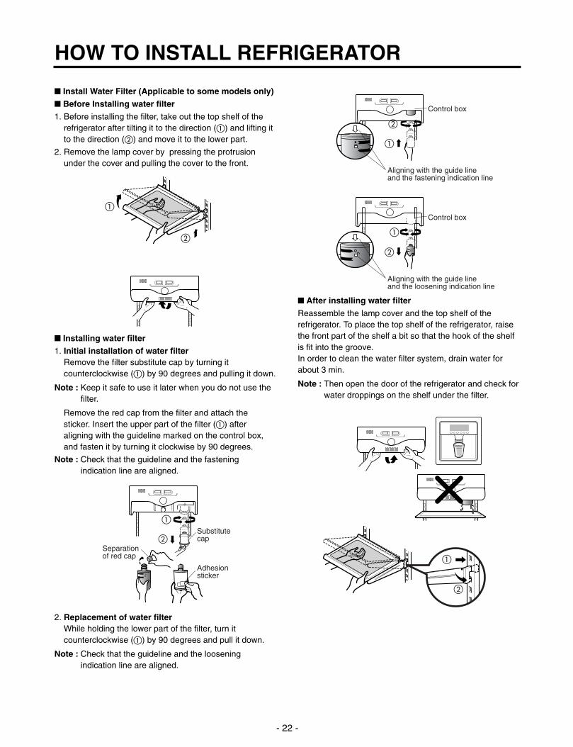
Install Water Filter (Applicable to some models only)
Before Installing water filter
1. Before installing the filter, take out the top shelf of therefrigerator after tilting it to the direction () and lifting itto the direction () and move it to the lower part.
2. Remove the lamp cover by pressing the protrusionunder the cover and pulling the cover to the front.
Installing water filter
1. Initial installation of water filterRemove the filter substitute cap by turning itcounterclockwise () by 90 degrees and pulling it down.
Note : Keep it safe to use it later when you do not use thefilter.
Remove the red cap from the filter and attach thesticker. Insert the upper part of the filter () afteraligning with the guideline marked on the control box,and fasten it by turning it clockwise by 90 degrees.
Note : Check that the guideline and the fasteningindication line are aligned.
2. Replacement of water filterWhile holding the lower part of the filter, turn itcounterclockwise () by 90 degrees and pull it down.
Note : Check that the guideline and the looseningindication line are aligned.
After installing water filter
Reassemble the lamp cover and the top shelf of therefrigerator. To place the top shelf of the refrigerator, raisethe front part of the shelf a bit so that the hook of the shelfis fit into the groove.In order to clean the water filter system, drain water forabout 3 min.
Note : Then open the door of the refrigerator and check forwater droppings on the shelf under the filter.
HOW TO INSTALL REFRIGERATOR
- 22 -
Control box
Aligning with the guide lineand the fastening indication line
Control box
Aligning with the guide lineand the loosening indication line
Separationof red cap
Adhesionsticker
Substitutecap

3. How to Control the Amount of Water Supplied to Icemaker.
3-1. Confirm the amount of water supplied to the icemaker.1. Pull out the ice bank in the upper part of the freezer compartment.
Caution : • Do not put hands or tools into the chute to confirmthe operation of geared motor. it may damage refrigerator or hurt hands.)
• Check the operation of motor with its operationnoise.
2. Apply electricity after connecting water pipe.
1) Press test switch under the icemaker for two seconds as shown below.
2) The bell rings(ding~dong) and ice tray rotates and water comes out from the icemaker water tube.
3) The water shall be supplied two or three times into the tray. The amount of water supplied for each time is small. Put a water container under the ice tray and press test switch.
4) When ice tray rotates, the water in it will spill. Collect the spilt water and throw away into the sink.
5) When ice tray has finished rotation, water comes out from the water tube. Confirm the amounts of water in the ice tray.(refer to fig. The optimum amount of water is 110cc)
* It is acceptable if the adjusted level of water is a bit smaller than optimum level.
HOW TO INSTALL REFRIGERATOR
- 23 -
Test Switch
Confirm the amount
of water
Ice maker
Too much
Too littleOptimum level

3-2. Control the amount of water supplied to theicemaker.
Caution : • Please unplug the power cord from the walloutlet and wait for more than three minutesbefore disconnecting PWB cover as 310V isapplied in the control panel.
1. Disconnect PWB cover from the upper part of therefrigerator.
2. Adjust the amount of water supplied by using DIPswitch.
Water Supplying Time Control Option
1) The water supplying time is set at five seconds when therefrigerator is delivered.
2) The amount of water supplied depends on the settingtime and water pressure (city water pressure).
3) If ice cube is too small, increase the water supplyingtime. This happens when too small water is supplied intothe ice tray.
4) If ice cube sticks together, decrease the water supplyingtime. This happens when too much water is suppliedinto the ice tray.
Caution : When adjusting the amount of water supplied,adjust step by step. Otherwise the water mayspill over.
3. When adjustment of control switch for the amount ofwater supplied is complete, check the level of water inthe ice tray.
HOW TO INSTALL REFRIGERATOR
- 24 -
SWITCH NO Water Suppling
S/W1 S/W2 S/W3 Time
OFF OFF OFF 6.5 Sec.
ON OFF OFF 5.5 Sec.
OFF ON OFF 6 Sec.
ON ON OFF 7 Sec.
OFF OFF ON 7.5 Sec.
ON OFF ON 8 Sec.
OFF ON ON 9 Sec.
ON ON ON 10 Sec.
(+) Driver 1
ONSwitch ON
Switch OFF 2 3
Confirm the amountof water
Optimum level

1. Monitor Panel
1-1. GR-P247, GR-P207, GR-L247, GR-L207 1-2. GR-C247, GR-C207, GR-B247, GR-B207
2. Description of Function2-1-1. Funnction of Temperature Selection
* The temperature can vary ±3 °C depending on the load condition.
Whenever pressing button, setting is repeated in the order of (Medium) (Medium Max) (Max) (Min) (Medium Min).
• The actual inner temperature varies depending on the food status, as the indicated setting temperature is a targettemperature, not actual temperature within refrigerator.
• Refrigeration function is weak in the initial time. Please adjust temperature as above after using refrigerator for minimum2~3 days.
MICOM FUNCTION
- 25 -
Super freezer.
Dispenser selection button.
Temperature adjustment buttonfor refrigerator compartment.
Lock button.
Filter reset button.
Temperature adjustment buttonfor freezer compartment.
ON
WATER
TEMP TEMP FILTER STATUS ROOM TEMP
LOCK
UNLOCK
654321
FILTER RESETPUSH 3 SEC
H
M
L
CUBED
CRUSHEDOFF
SUPER FRZ DISPENSER FRZ TEMP REF TEMP FILTER RESET LOCK CONTROL
TEMP
TEMP ROOM TEMP
UNLOCKLOCK
Division Power Initially On 1st Press 2st Press 3th Press 4th Press
Setting temperature
Temperature Control
Medium Medium Max Max Min Medium Min
Freezer Control -19 °C -22 °C -23 °C -15 °C -17 °C
Refrigeration 3 °C 2 °C 0°C 6 °C 4 °C
Control
H
M
L
H
M
L
H
M
L
H
M
L
H
M
L

2-1-2. LCD Back Light Control
1. In order to easily view display status on the LCD, LCD Back Light is turned on for a minute in application of initial power,for a minute in button manipulation and for a minute after closing time from opening time of door.
2. If pressing any display button once with the backlight turned off, buzzer rings and button function is not performed butonly backlight is turned on (If pressing the first button with the back light turned off, only back light ON function isperformed).
3. If pressing the special freezing button and the freezing temperature adjustment button for more than a second, the backlight is turned on and all the graphics of LCD are turned on. If releasing the button, the LCD graphic is displayed in theprevious status and the back light is turned off (check LCD graphic and back light ON/OFF status).
2-1-3. Outside temperature display function
1. Outside temperature sensor at the left U of refrigerator senses ambient temperature and displays the outside temperaturein the left side of “Outside temperature” text on the LCD of the display part.
2. Ambient temperature is displayed up to -9°C ~ 49°C and displayed as “Lo” for less than -10°C and as “HI” for more than50°C. If the ambient temperature sensor fails, it is displayed as “Er”.
3. Since display temperature of outside temperature is temperature sensed by the ambient sensor in the hinge U of thefreezing room, it may differ from the outside temperature display of other household electrical appliances.
2-1-4. Lock function (display button lock)
1. In power application of refrigerator, the only “Release” text is turned on at the right side of lock graphic of LCD with thelock release status.
2. If desiring to lock the display status and pressing the lock/release button once, “Release” text is turned off at the right sideof lock graphic of LCD and “Lock” text is turned on with lock status.
3. The buzzer sound and function is not performed even if pressing display button other than lock/release key in the lockstatus.
4. If desiring to release the lock status and pressing the lock/release button once, “Lock” text is turned off at the right side oflock graphic of LCD and “Release” text is turned on with lock release status.
2-1-5. Filter condition display function
1. As demonstrated below, it displays the months left in units of 30 days until the filter replacement is required, starting fromwhen the refrigerator power usage is authorized.
2. After 6 months, the following sentence and will appear on the filter condition part of the LCD. "Press for 3seconds after replacing filter"
3. After 6 months have passed, and if the filter has been replaced or you want to reset the filter condition display, press thefilter replacement button for more than 3 seconds and it will reset to the initial Power On state.
MICOM FUNCTION
- 26 -
FILTER RESETPUSH 3 SEC.
FILTER STATUS
654321
654321
654321
654321
654321
654321
654321
In initialPower OnClassification
Filter StatusDisplay
Pass ofa month
Pass of2 months
Pass of3 months
Pass of4 months
Pass of5 months
Pass of6 months
FILTER STATUS FILTER STATUS FILTER STATUS FILTER STATUS FILTER STATUS FILTER STATUS
FILTER RESETPUSH 3 SEC.

2-2. Dispenser use selectionYou can select water or ice.
Please select water, slice ice and square ice by pressing button as you desire.
Please press the push button lightly by catching and pushing in cup. • The border line is indicated for the selected function.
• “Tak!” sounds if 5 seconds pass after ice comes out. It is sound that the outlet of ice is closed.
REFERENCE : Please wait for 2-3 seconds in order to take final ice slices or drops ofwater when taking out cup from the pressing switches after taking iceor water.
2-3. Automatic ice maker• The automatic ice maker can automatically make 8 pieces of ice cube at a time, 80 pieces a day. But these quantities may
be varied according to various conditions including how many times the refrigerator door opens and closes.
• Ice making stops when the ice storage bin is full.
• If you don’t want to use automatic ice-maker, change the ice-maker switch to ON-OFF.If you want to use automatic ice-maker again, change the switch to OFF-ON.
NOTE : It is normal that a noise is produced when ice made is dropped into the ice storage bin.
2-4. When ice maker does not operate smoothlyIce is lumped together
• When ice is lumped together, take the ice lumps out of the ice storage bin, break them into small pieces, and then placethem into the ice storage bin again.
• When the ice maker produces too small or lumped together ice, the amount of water supplied to the ice maker need toadjusted. Contact the service center.
If ice is not used frequently, it may lump together.
Power failure
• Ice may drop into the freezer compartment. Take the ice storage bin out and discard all the ice then dry it and place itback. After the machine is powered again, crushed ice will be automatically selected.
The unit is newly installed
• It takes about 12 hours for a newly installed refrigerator to make ice in the freezer compartment.
2-5. Super freezerPlease select this function for prompt freezer.
• “On” or “Off” is repeated whenever pressing button.
• The arrow mark graphic remains at the On status after flickering 4 times whenselecting Special Refrigeration “On”.
• Super freezer function automatically turns off if a fixed time passes.
2-6. LockThis button stops operation of different button.
• Locking or Release is repeated whenever pressing the .
• Pressing the other button when selecting ‘LOCK’, the button does not operate.
MICOM FUNCTION
- 27 -
Ex) In selecting"On"
Ex) In selecting"Off"
Ex) In selecting"LOCK"
Ex) In selecting"LOCK" again
ONSUPER FRZ
OFF
LOCK CONTROLLOCK
UNLOCK
DISPENSERWATER
CUBED
CRUSHED
Pressing Switch
DISPENSER
SUPER FRZ
LOCK CONTROL

2-7. Super freezing1. Super freezing is function to improve cooling speed of the freezing room by consecutively operating compressors and
freezing room fan. If pressing the super freezing button, “Turn Off” text of the LCD panel is turned off and “Turn On” isimmediately turned on and “Arrow ( )” graphic is turned on after flickering once.
2. super freezing is cycled in order of Selection/ Release (“Turn On” / “Turn Off”) whenever pressing the selection button.
3. super freezing is released if power failure occurs and then returns to the original status.
4. Temperature setting is not changed even if selecting the super freezing.
5. The change of temperature setting at the freezing room or the cold storage room is allowed with super freezing selectedand processed.
6. The cold storage room operates the status currently set with super freezing selected and processed.
7. If selecting the super freezing, the super freezing function is released after continuously operating compressor andfreezing room fan.
8. If frost removal starting time is arrived during super freezing, super freezing operation is done only for the remaining timeafter completion of frost removal when the super freezing operation time passes 90 minutes. If passing 90 minutes, superfreezing operation is done only for 2 hours after completion of frost removal.
9. If pressing super freezing button during frost removal, the super freezing LCD is turned on but if pressing the superfreezing, compressor operates after the remaining time has passed.
10. If selecting super freezing within 7 minutes (delay for 7 minutes of compressor) after the compressor stops, compressoroperates after the remaining time has passed.
11. The freezing room fan motor operates at the high speed of RPM during operation of super freezing.
2-8. Miracle Zone function1. Miracle Zone is located at the bottom room of R-room and maintains optimum temperature depending on foods through
selection of desired foods kept in the Miracle Zone from vegetables to meat with a display.Set temperature in the Miracle Zone by using a separate selection button at the right side of the Miracle Zone. Initialnotch is in “veg.”status in application of power. Whenever pressing buttons, notch changes while LED is displayed in theorder of “veg. cheeze meat veg.”.Provided that selected notch LED turns off if opening doors of the R-room and it turns off if closing doors of R-room.
2. Temperature of the miracle zone is controlled with a stemping damper at the left side of the miracle zone and controlledwith a miracle zone at the rear side of miracle zone.
3. Change of the notch by temperature control S/W at the miracle zone is controlled after 10 seconds have passed afterselecting final notches.
4. Miracle zone damper is forcedly closed during test mode or defrost mode.
2-9. Control of variable type of freezing room fan1. To increase cooling speed and load response speed, MICOM variably controls freezing room fan motor at the high speed
of RPM and standard RPM.
2. MICOM only operates in the input of initial power or super freezing operation or load response operation for the highspeed of RPM and operates in the standard RPM in other general operation.
3. If opening doors of freezing / cold storage room or home bar while fan motor in the freezing room operates, the freezingroom fan motor normally operates (If being operated in the high speed of RPM, it converts operation to the standardRPM). However, if opening doors of freezing room or home bar, the freezing room fan motor stops.
4. As for monitoring of BLDC fan motor error in the freezing room, MICOM immediately stops the fan motor by determiningthat the BLDC fan motor is locked or poor if there would be position signal for more than 65 seconds at the BLDC motor.Then it displays failure (refer to failure diagnosis function table) at the display part of refrigerator, performs re-operation inthe cycle of 30 minutes. If normal operation is performed, poor status is released and refrigerator returns to the initialstatus (reset).
MICOM FUNCTION
- 28 -
Miracle Zone NOTCH meat cheeze veg.
Setting Indication -1°C 2°C 4°C

- 29 -
2-10. Control of M/C room fan motor1. The M/C room fan motor performs ON/OFF control by linking with the COMP.
2. It controls at the single RPM without varying RPM.
3. Failure sensing method is same as in fan motor of freezing fan motor (refer to failure diagnosis function table for failuredisplay).
2-11. Door opening alarm1. Buzzer generates alarm sound if doors are not closed even when more than a minute consecutively has passed with
doors of freezing / cold storage room or home bar opened.
2. Buzzer rings three times in the interval of 0.5 second after the first one-minute has passed after doors are opened andthen repeats three times of On/Off alarm in the cycle of every 30 seconds.
3. If all the doors of freezing / cold storage room or home bar are closed during door open alarm, alarm is immediatelyreleased.
2-12. Ringing of button selection buzzer1. If pressing the front display button, “Ding ~ “ sound rings.
2-13. Ringing of compulsory operation, compulsory frost removal buzzer1. If pressing the test button in the main PCB, “Phi ~ “ sound rings.
2. In selecting compulsory operation, alarm sound is repeated and completed in the cycle of On for 0.2 second and Off for1.8 second three times.
3. In selecting compulsory frost removal, alarm sound is repeated and completed in the cycle of On for 0.2 second , Off for0.2 second, On for 0.2 second and Off for 1.4 second three times.
2-14. Frost removal function1. Frost removal is performed whenever total operation time of compressor becomes 7 ~ 7.5 hour.
2. In providing initial power (or returning power failure), frost removal starts whenever total operation time of compressorbecomes 4 ~ 4.5 hour.
3. Frost removal is completed if temperature of a frost removal sensor becomes more than 5°C after starting frost removal.Poor frost removal is not displaced if it does not arrive at 5°C even if two hours have passed after starting frost removal.
4. No removal is done if frost removal sensor becomes poor (snapping or short-circuit).
Doors of freezing / cold storage room
or home bar
BUZZER
Closing Opening
Withina minute
A minute 30seconds
30seconds
30seconds
OpeningClosing Closing
3 Times 3 Times 3 Times 3 Times
MICOM FUNCTION

2-15. Sequential operation of built-in productBuilt-in products such as compressor, frost removal heater, freezing room fan, Cooling Fan and step motor damper aresequentially operated as follows for preventing noise and part damage occurred due to simultaneous operation of a lot ofparts in applying initial power and completing test.
MICOM FUNCTION
- 30 -
Function Load Operation Sequence Remark
Inapplying
Initialpower
TE
ST
MO
DE
When temperatureof a frost removalsensor becomesmore than 45°C (In purchase,movement)
If error occursduring operation,initial operation isnot done.
Sequence ofload operationwhen closing F-room and R-room.
If pressing switchonce more in thetest mode 2 ortemperature of afrost removalsensor is morethan 5°C, itimmediatelyreturns to the testmode for initialoperation (COMP operatesafter 7 minutes).
Whentemperature of afrost removalsensor becomesless than 45°C (In power failure,service)
Test mode 1 (Compulsoryfunction)
Test mode 2 (Compulsory frostremoval)
POWER
ON
COMP
ON
F-FAN&
C-FANON
R-STEPMOTOR
DAMPERON
HOMEBAR
HEATERON
MIRACLEZONESTEP
DAMPERMOTOR
ON
FROSTREMOVALHEATER
OFF
HOMEBAR
HEATERON
HOMEBAR
HEATEROFF
FROSTREMOVALHEATER
ON
DAMPER&
DUCT DOORHEATER
ON
DAMPER&
DUCT DOORHEATER
OFF
0.3sec.
0.3sec.
0.3sec.
0.3sec.
0.3sec.
0.3sec.
0.3sec.
POWER
ON
PIPE&
DISP'HEATER
ON
0.3sec.
PIPE&
DISP'HEATER
OFF
0.3sec. COMP
ON
0.3sec. F-FAN
&C-FAN
ON
0.3sec. R-STEP
MOTORDAMPER
ON
0.3sec.
MIRACLEZONESTEP
DAMPERMOTOR
ON
0.3sec. HOME
BARHEATER
ON
TESTS/W
(PRESSOnce)
OTHERLOAD
OFF
COMP
ON
F-FAN&
C-FANON
R-STEPMOTOR
DAMPERON
MIRACLEZONESTEP
DAMPERMOTORCLOSE
TESTS/W
(PRESS2 Times)
COMP
OFF
F-FAN&
C-FANOFF
FROSTREMOVALHEATER
ON
R-STEPMOTOR
DAMPERCLOSE
0.3sec.
0.3sec.
0.3sec.
0.3sec.
0.3sec.
0.3sec.
0.3sec.
0.3sec.
0.3sec.
0.3sec.
0.3sec.
0.3sec.

2-16. Failure Diagnosis Function1. Failure diagnosis function is function to facilitate service when nonconforming matters affecting performance of product
during use of product.2. In occurrence of failure, pressing the function adjustment button does not perform function.3. If nonconforming matters occurred are released during display of failure code, MICOM returns to the original state (Reset).4. Failure code is displayed on the display part of setting temperature for the freezing room and the display part of setting
temperature for the cold storage room of LCD, which are placed at the display part of a refrigerator. All the LCD graphicsother than a failure code are turned off.
All LCDs turn off other than freezer room notch temperature display and refrigerator room notch temperaturedisplay(failure code indication part) in case of indicating failure modes(except for Note1, Note2).
MICOM FUNCTION
BASIC DELUXE
1
2
3
4
5
6
7
8
9
10
11
12
Er FS
Er rS
Normal display (Note 2)
Er dS
Er dH
Er FF
Er CF
Er CO
Normal display (Note 1)
Normal display (Note 2)
Normal display (Note 2)
Normal display(Note 2)
Failure code indication part
Freezer room notch temperature
display
Refrigerator roomnotch temperature
display
No. Item Contents of failure FreezingBLDC motorCompressor Stepping
motor damperDefrostHeater
CoolingBLDC motor
Product operation status in failure
Abnormalfreezer sensor
Abnormal refrigeratorsensor1(R1) (Upper part in therefrigeratorcompartment)
Abnormal refrigeratorsensor2(R2) (Upper part in therefrigeratorcompartment)
Abnormal defrostsensor
Failed defrosting
Abnormal freezingBLDC motor
Abnormal coolingBLDC motor
Abnormalcommunication
Abnormalambient sensor
Abnormal ice-maker sensor
Abnormal ice-maker unit
Abnormal miracle zone sensor
Freezer sensor short circuit
Refrigerator sensor1 short circuit
Refrigerator sensor2 short circuit
Abnormal short circuit
Defrost heater, temperature fuse shortcircuit, unplugged connector(indicated4 hour later after trouble)
Motor defect, hooked of lead wireto fan, contact of structures withfan, short or open of leadwire(there is no signal of BLDCmotor more than 65 seconds inoperation of fan motor)
Short or open of lead wireconnecting betwee main PCBand display PCB, transmission trand receiving part
Ambient sensor short circuit
Ice-maker sensor short circuit
Faulty ice-maker unit motor or hallic, lead wire short circuit, faultymotor driving circuit
Miracle zone sensor short circuit
StandardRPM
StandardRPM
StandardRPM
StandardRPM
StandardRPM
OFF (check of 30-minutes cycle)
StandardRPM
StandardRPM
OFF (check of30-minutes cycle)
ON for 15minutes /OFF for 15minutes
No defrost
Full opening for10 minutes/
Full closing for15 minutes
: Proper operation
- 31 -

Note1) Freezer room notch temperature display and refrigerator room notch temperature display(Failure code indicationpart) are normally indicated in abnormal ambient sensor, and “Er” indicated on the amvient temperaturedisplay(except for the ambient temperature display, other LCDs are indicated normally)
Note2) R2-sensor, Ice-maker sensor miracle zone sensor and Ice-maker kit is not indicated on the failure indicating part butindicated in checking LCD(When pressing for more than the button of freezing temperature and super freezer buttonfor more than 1 second).
R2-sensor(middle room)Normal: LCD graphic on the (C) part turns on Abnormal: LCD graphic on the (C) part turns off
Ice-making sensorNormal: LCD graphic on the (D) part turns onAbnormal: LCD graphic on the (D) part turns off
Ice-maker unitNormal: LCD graphic on the (E) part turns onAbnormal : LCD graphic on the (E) part turns off
Miracle zone sensorNormal: LCD graphic on the (F) part turns onAbnormal : LCD graphic on the (F) part turns off
2-17. Test Function1. The purpose of test function is to check function of the PWB and product and to search for the failure part at the failure
status.
2. Test button is placed on the main PCB of refrigerator (test switch), and the test mode will be finished after maximum 2hours irrespective of test mode and then is reset to the normal status.
3. Function adjustment button is not perceived during performance of test mode.
4. In finishing test mode, always pull the power cord out and then plug-in it again for the normal state.
5. If nonconforming contents such as sensor failure are found during performance of test mode, release the test mode anddisplay the failure code.
6. Even if pressing the test button during failure code display, test mode will not be performed.
MICOM FUNCTION
- 32 -
The other LCD Graphics Turn On.
Test 1
Test 2
NormalStatus
Mode Operation Contents Remarks
Press test button once(strong cold mode)
Press test button once atthe test mode 1 status(forced defrost mode)
Press test button once atthe test mode 2 status
1. Continuous operation of compressor2. Continuous operation of freezing bldc motor
(high-speed RPM) and cooling bldc motor3. Defrost heater turns off4. Stepping motor damper is completely
opened (open of baffle)5. Miracle zone stepping motor damper is
completely closed.6. All display LCD graphics turns on.
1. Compressor OFF2. Freezing bldc motor and cooling bldc motor
turn off3. Defrost heater turns on4. Stepping motor damper is completely
closed (closing of baffle)5. Miracle zone stepping motor damper is
completely closed.6. All display LCD graphics turns off (only LCD
turns on for(A) “MIDIUM” status, (B)“MIDIUM” status)
Return to the initial status.
Freezing fan turns off indoor opening
Return to the normal modewhen the defrost sensor isabove +5°C
Compressor will operateafter delay for 7 minutes

LCD check function: If simultaneously pressing super freezer button and freezing temperature adjustment button for asecond, a back light is turned on and all display LCD graphics on. If releasing the button, the LCDgraphic displays the previous status, the back light is turned off (LCD graphic and back light ON/OFFcheck).
2-18. Function of dispenser and water dispenser built-in1. This is function allowing ice and water to come outside without opening door.
2. If pressing the dispenser switch (rubber button) after selecting ice (cube ice, crushed ice) or water, ice and waterequivalent to each come out. However, the duct doors are opened by electrical solenoid valve (Duct Door Solenoid) ifpressing the press switch in case of selecting ICE. If pressing the dispenser press switch and then detaching the hands,the duct door is closed after it is opened for 5 seconds.
3. Function allowing ice and water to come stops if freezing room doors are opened.
4. If there is no Off signal even when 3 minutes have passed while pressing the dispenser press switch after selecting ice(cube ice, crushed ice) or water, geared motor and solenoid (Cube, Water) is automatically turned off. However, thesolenoid (duct door) is stop 5 seconds after Off (to prevent short-circuit of a coil due to overheat of solenoid).
5. Dispenser Lamp On/Off function Lamp on the dispenser part is turned on if pressing the dispenser press switch after selecting ice (cube ice, crushed ice)or water. If detaching the hands, it is turned off.
6. Selection function of water/crushed/ cube ice 1) This is function to allow selection of water/crushed/ cube ice function depending on user’s selection. Display and
selection is done if pressing the dispenser selection button.2) In the initial Power On, cube ice is automatically selected.3) In selecting cube ice, geared motor is operated so that crushed ice can be supplied outside if pressing the press switch
when ice is formed in the ice storage container (Bank, Ice).4) In selecting cube ice, geared motor is operated so that cube ice can be supplied outside if pressing the press switch
when ice is formed in the ice storage container (Bank, Ice).
7. Water dispenser function1) LCD is displayed for selection if user selects water at the function adjustment part.2) Water dispenser function is a type directly connected to a water pipe. The water solenoid valve built-in at the right side
of the M/C room is opened so that water can be supplied if selecting Water from the function adjustment part and thenpressing the press switch.
MICOM FUNCTION
- 33 -
<TEST MODE 1 STATUS LCD>
<TEST MODE 2 STATUS LCD>
ON
WATER
TEMP TEMP FILTER STATUS ROOM TEMP
LOCK
UNLOCK
654321
FILTER RESETPUSH 3 SEC
H
M
L
CUBED
CRUSHEDOFF
H
M
L
TEMP
TEMP ROOM TEMP
UNLOCKLOCK

1. Explanation for PWB circuit
1-1. Power circuit1. GR-P247, L247, C247, B247 / P207, L207, C207, B207
Power circuit consists of SMPS (SWITCHING MODE POWER SUPPLY) power. The SMPS consist of the rectifying part(BD1, CE1) converting AC voltage to DC voltage, the switching part (IC2) switching the converted DC voltage, transformertransferring energy of the primary side of the switching terminal to the secondary side and the feedback part (IC3, IC4)transferring it to the primary side.
Caution : Since high voltage (DC310V) is maintained at the power terminal, please take a measure after more than 3minutes have passed after removing power cords in the abnormal operation of a circuit.
Voltage of every part is as follows:
EXPLATION FOR MICOM CIRCUIT
- 34 -
Part VA1 CE1 CE2 CE3 CE4 CE5
Voltage 230 Vac 310 Vdc 16 Vdc 12 Vdc 16 Vdc 5 Vdc

1-2. Oscillation circuitOscillation circuit is a circuit with the purpose of generating basic time for clock occurrence for synchronization and timecalculation in relation with information transmission/reception of inside elements of IC1 (MICOM). The OSC1 must alwaysuse rated parts since if SPEC is changed, time calculated at the IC1 may be changed or no operation is done.
1-3. Reset circuitThe reset circuit is circuit allowing various parts such as RAM inside of MICOM (IC1) to initialize and the whole of function tostart from the initial status, when initial power is input or when power is applied again to MICOM by a spontaneous powerfailure. ‘LOW’ voltage is applied to the reset terminal of MICOM in the beginning of power supply for a constant time (10ms). Reset terminal during general operation is 5V (No MICOM operates in failure of RESET IC).
EXPLATION FOR MICOM CIRCUIT
- 35 -
<GR-P247, L247, P207, L207> <GR-C247, B247, C207, B207>
<GR-P247, L247, P207, L207> <GR-C247, B247, C207, B207>

1-4. Load/dispenser operation, door opening circuit
1. LOAD DRIVING CIRCUIT In even if opening the door of freezing room or cold storage room during operation of fan motor at the freezing room, this
circuit does not stop and operates at the standard RPM. In addition, if doors of freezing room or cold storage room, thefan motor normally operates at the RPM previously operated.
(A), (B), (C) and (D) of door switch for the freezing room or cold storage room are connected to the door open sensingcircuit in parallel toward both ends of switch to determine door open at MICOM.
Since a door switch of the home bar is connected to door switch (C), (D) of the cold storage room, it senses door openingif even one of both is opened.
The fan motor is immediately stop if opening doors of the freezing room or cold storage room at the TEST mode and itimmediately operates if closing them.
1) GR-P247, L247, P207, L207
EXPLATION FOR MICOM CIRCUIT
- 36 -
Measuring part (IC6) NO.16 NO.12 NO.11 NO.15 NO.13 IC7-11 IC7-10
StatusON Within 1 V
OFF 12 V
Type of Load COMP'Frost
RemovalHeater
ACConverting
Relay
R-roomLAMP
Pipe & Disp'Heater
Home BarHeater
DamperHeater
Duct DoorHeater

2) GR-C247, B247, C207, B207 The fan motor at the freezing room does not stop but operates if opening doors of the freezing room or cold storage room
or the home bar during operation of the fan motor at the freezing room. (A), (B), (C) and (D) of door switch for the freezing room or cold storage room are connected to the door open sensing
circuit toward both ends of switch to determine door open at MICOM. Since a door switch of the home bar is connected to door switch (C), (D) of the cold storage room, it senses door opening
if even one of both is opened.
EXPLATION FOR MICOM CIRCUIT
- 37 -
6 P76(AIN15)
Measuring part (IC7) No.16 No.11 No.10 No.15 No.14
StatusON Within 1 V
OFF 12 V
Type of Load COMPFrost Removal
HeaterAC Converting
RelayR-room LAMP
Home BarHeater

2. Dispenser operation circuit
1) Check load driving status
2) Lever S/W sensing circuit
EXPLATION FOR MICOM CIRCUIT
- 38 -
Measuring part
Lever S/WIC1(Micom) (No. 16)
On(Press)
OFF 5V
0 V(60 Hz)
5 V
Measuring part IC6-10 IC6-16 IC6-15 IC6-14 IC7-12 IC7-13
StatusON Within 1 V
OFF 12 V
Type of LoadGEAREDMOTOR
SOLENOIDCUBE
WATER VALVE
ICE WATER
SOLENOIDDISPENSER
SOLENOIDPILOT

3. Door opening sensing circuit
1) GR-P247, L247, P207, L207
2) GR-C247, B247, C207, B207, 197
Since door switch sensing switch (A), (B) are a separate switch even if the door switch of the freezing room normallyoperates, they may fail to sense door opening in the failure of switch at both ends of (A) and (B) or in failure of the L/wire.
Lamp does at the cold storage room not turn on if the door switch of the cold storage room fails to sense the door openswitch (C), (D) or the home bar switch.
EXPLATION FOR MICOM CIRCUIT
- 39 -
Closing 5 V ( A - B , C - D . S/W at both ends are at Off status)
Opening 0 V ( A - B , C - D . S/W at both ends are at On status)
Measuring partIC1 (MICOM) No. 47, 46 Pin
Door of Freezing/Cold Storage Room

1-5. Temperature sensing circuit1) GR-P247, L247, P207, L207
The above circuits are circuits attached to freezing room sensor or cold storage room sensor for adjusting settingtemperature at the freezing room and cold storage room, ice-making sensor for sensing water temperature in ice-making, oran evaporator for sensing temperature of a frost removal sensor necessary for frost removal. Short or open status of everytemperature sensor is as follows:
EXPLATION FOR MICOM CIRCUIT
- 40 -
SENSOR CHECK POINT NORMAL(-30 °C ~ 50 °C) IN SHORT IN OPEN
Freezing sensor POINT A Voltage
Frost removal sensor POINT B Voltage
Cold storage sensor 1 POINT C Voltage0.5 V~4.5 V 0 V 5 V
Cold storage sensor 2 POINT D Voltage
Ice-making sensor POINT E Voltage
Room temperature sensor POINT F Voltage

2) GR-C247, B247, C207, B207
The above circuits are circuits attached to freezing room sensor or cold storage room sensor for adjusting settingtemperature at the freezing room and cold storage room, ice-making sensor for sensing water temperature in ice-making, oran evaporator for sensing temperature of a frost removal sensor necessary for frost removal. Short or open status of everytemperature sensor is as follows:
EXPLATION FOR MICOM CIRCUIT
- 41 -
SENSOR CHECK POINT NORMAL(-30 °C ~ 50 °C) IN SHORT IN OPEN
Freezing sensor POINT A Voltage
Frost removal sensor POINT B Voltage
Cold storage sensor 1 POINT C Voltage 0.5 V~4.5 V 0 V 5 V
Cold storage sensor 2 POINT D Voltage
Room temperature sensor POINT E Voltage

1-6. Switch entry circuitThe following circuits are entry circuits for sensing signal form test S/W, electronic single motor damper reed S/W forexamining refrigerator.
1) GR-P247, L247, P207, L207 2) GR-C247, B247, C207, B207
1-7. Option designation circuit (model separation function)1) GR-P247, L247, P207, L207
2) GR-C247, B247, C207, B207
The above circuits are used for designating separation by model as option and notifying it to MICOM. Designation of optionby model and the application standards are as follows:
u These circuits are accurately pre-adjusted in shipment from factory and so you must not additionally add or removeoption.
EXPLATION FOR MICOM CIRCUIT
- 42 -
Separation Connection Status Application Standard
Connection All export model except Australia, New Zealand, Taiwan OP1
OUT Australia, New Zealand, Taiwan

1-8. Stepping motor operation circuit (cold storage room, Miracle Zone)
For motor driving method, rotation magnetism is formed at coils wound on each phase of motor and stator and so motorbecomes to rotate if applying “High” signal to the IC8 (TA777AF) at the MICOM PIN 33 and outputting “High”, “Low” signalby step numbers fixed through MICOM PIN 34 and 35,.
Explanation) For driving method of the stepping motor, send signals in the cycle of 3.33 mSEC using terminal of MICOMPIN 33, 34 and 35 as shown in wave form of the following part. These signals are output to the output terminal (No.10, 11, 14, 15) via the input terminal (No. 3, 6, 8) of theIC10 (TA7774F) as IC for motor driving. Output signals allow motor coils wound on each phase of stator toform rotation magnetic field and the motor to rotate. Inputting as below figure to the input terminal (INA, INB)as IC (TA7774AF) for motor driving allows motor coils wound on each phase of stator to form rotationmagnetic field and the stepping motor damper to rotate
EXPLATION FOR MICOM CIRCUIT
- 43 -
TA7774F
INA
INB
A
B
A
B
CCW (Reverse rotation) (Positive rotation) CW

1-9. Fan motor driving circuit (freezing room, M/C room)1. This circuit performs function to make standby power ‘0’ by cutting off power supplied to ICs inside of the fan motor in the
fan motor OFF.
2. This is a circuit to perform a temporary change of speed for the fan motor and applies DC voltage up to 7.5V ~ 16V tomotor.
3. This circuit performs function not to drive the fan motor further by cutting off power applied to the fan motor in the lock offan motor by sensing the operation RPM of the fan motor.
1) GR-P247, L247, P207, L207
EXPLATION FOR MICOM CIRCUIT
- 44 -
a , d part b part e part
Motor OFF 5V 2V or less 2V or less
Motor ON 2 ~ 3V 12 ~ 14V 8 ~ 16V
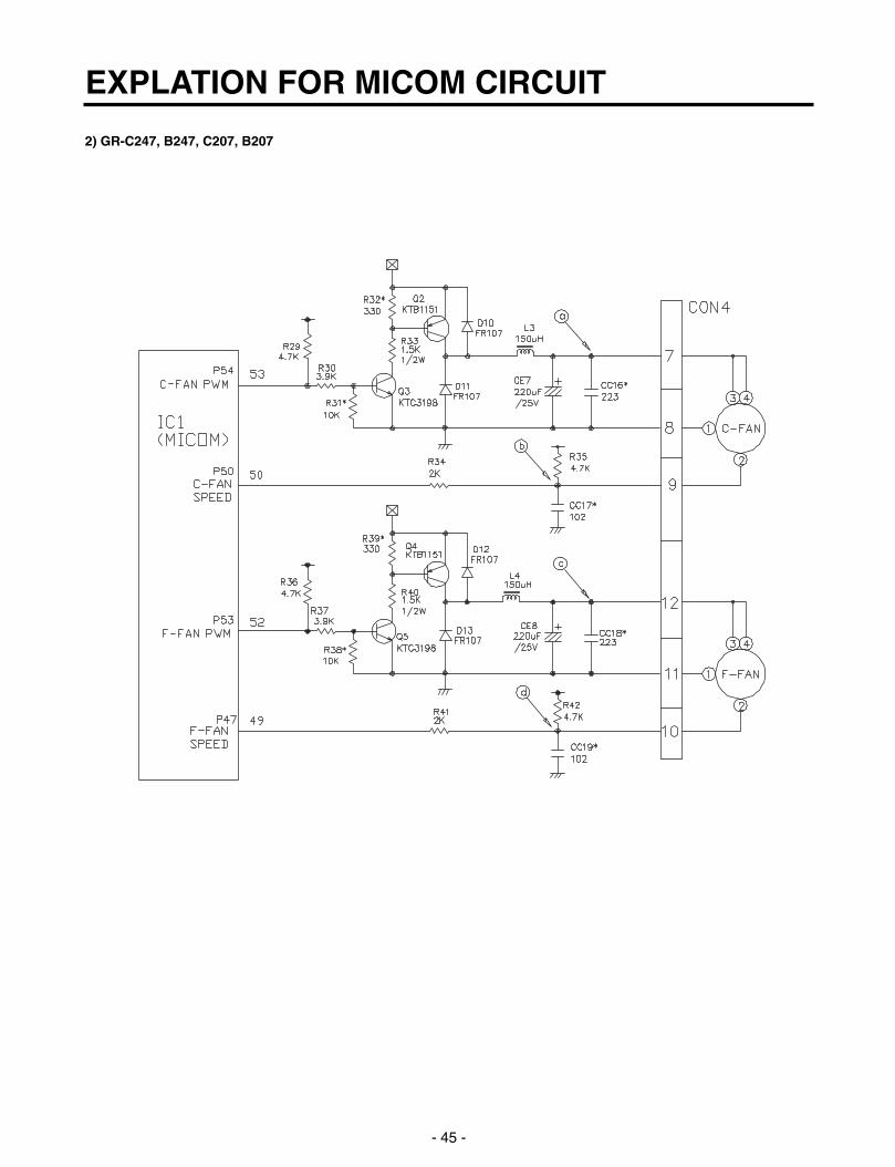
2) GR-C247, B247, C207, B207
EXPLATION FOR MICOM CIRCUIT
- 45 -

1-10. Temperature compensation and over-cool/weak-cool compensation circuit1. Temperature compensation at freezing room, cold storage room
1) GR-P247, L247, P207, L207
2) GR-C247, B247, C207, B207
u Temperature compensation table by adjustment value (difference value against current temperature) Ex) If changing compensation resistance at a cold storage room (RCR1) from 10 kΩ (current resistance) to 18 kΩ
(modified resistance), temperature at the cold storage will increase by +1°C.
EXPLATION FOR MICOM CIRCUIT
- 46 -
Freezing room Cold storage room
Resistance value Temperature Resistance value Temperature Remarks(RCF1) compensation (RCR1) compensation
180 kΩ +5 °C 180 kΩ +2.5 °C Warmly
56 kΩ +4 °C 56 kΩ +2.0 °C compensate
33 kΩ +3 °C 33 kΩ +1.5 °C
18 kΩ +2 °C 18 kΩ +1.0 °C
12 kΩ +1 °C 12 kΩ +0.5 °C
10 kΩ 0 °C 10 kΩ 0 °C Reference temperature
8.2 kΩ -1 °C 8.2 kΩ -0.5 °C
5.6 kΩ -2 °C 5.6 kΩ -1.0 °C
3.3 kΩ -3 °C 3.3 kΩ -1.5 °C
2 kΩ -4 °C 2 kΩ -2.0 °C Coolly
470 Ω -5 °C 470 Ω -2.5 °C compensate

u Temperature compensation table at the cold storage room is as follows:
u Temperature compensation at the freezing room is also performed in the same manner as cold storage room.Temperature compensation value is equivalent to two times the cold storage room.
u This circuit is a circuit to enter the necessary level of temperature compensation for adjusting different temperature everymodel at the cold storage room into MICOM.
EXPLATION FOR MICOM CIRCUIT
- 47 -
470 Ω 2 kΩ 3.3 kΩ 5.6 kΩ 8.2 kΩ 10 kΩ 12 kΩ 18 kΩ 33 kΩ 56 kΩ 180 kΩ
No 0.5 °C 1 °C 1.5 °C 2 °C 2.5 °C 3 °C 3.5 °C 4 °C 4.5 °C 5 °C470Ω change Up Up Up Up Up Up Up Up Up Up
0.5 °C No 0.5 °C 1 °C 1.5 °C 2 °C 2.5 °C 3 °C 3.5 °C 4 °C 4.5 °C2 kΩ Down change Up Up Up Up Up Up Up Up Up
1 °C 0.5 °C No 0.5 °C 1 °C 1.5 °C 2 °C 2.5 °C 3 °C 3.5 °C 4 °C3.3 kΩ Down Down change Up Up Up Up Up Up Up Up
1.5 °C 1 °C 0.5 °C No 0.5 °C 1 °C 1.5 °C 2 °C 2.5 °C 3 °C 3.5 °C5.6 kΩ Down Down Down change Up Up Up Up Up Up Up
2 °C 1.5 °C 1 °C 0.5 ° No 0.5 °C 1 °C 1.5 °C 2 °C 2.5 °C 3 °CCold storage 8.2 kΩ Down Down Down Drop change Up Up Up Up Up Up
room 2.5 °C 2 °C 1.5 °C 1 °C 0.5 °C No 0.5 °C 1 °C 1.5 °C 2 °C 2.5 °C(RCR1) 10 kΩ Down Down Down Down Down change Up Up Up Up Up
3 °C 2.5 °C 2 °C 1.5 °C 1 °C 0.5 °C No 0.5 °C 1 °C 1.5 °C 2 °C12 kΩ Down Down Down Down Down Down change Up Up Up Up
3.5 °C 3 °C 2.5 °C 2 °C 1.5 °C 1 °C 0.5 °C No 0.5 °C 1 °C 1.5 °C18 kΩ Down Down Down Down Down Down Down change Up Up Up
4 °C 3.5 °C 3 °C 2.5 °C 2 °C 1.5 °C 1 °C 0.5 °C No 0.5 °C 1 °C33 kΩ Down Down Down Down Down Down Down Down change Up Up
4.5 °C 4 °C 3.5 °C 3 °C 2.5 °C 2 °C 1.5 °C 1 °C 0.5 °C No 0.5 °C56 kΩ Down Down Down Down Down Down Down Down Down change Up
5 °C 4.5 °C 4 °C 3.5 °C 3 °C 2.5 °C 2 °C 1.5 °C 1 °C 0.5 °C No180 kΩ Down Down Down Down Down Down Down Down Down Down change
Modificationresistance
Currentresistance

2. Compensation circuit for weak-cold, over-cold at freezing room
1) GR-P247, L247, P207, L207 2) GR-C247, B247, C207, B207
u The above option circuit is a circuit to compensate for temperature at the cold storage room by simply cutting in service.
EXPLATION FOR MICOM CIRCUIT
- 48 -
Compensation Compensation for weak-cold for over-cold Temperature compensation value Remarks
JCR3 JCR4 JCR1 JCR2at cold storage room
0 °C (In shipment from factory)
CUT -1 °C
CUT -1 °C
CUT +1 °C
CUT +1 °C
CUT CUT -2 °C
CUT CUT +2 °C
CUT CUT 0 °C
CUT CUT 0 °C
CUT CUT 0 °C
CUT CUT 0 °C
CUT CUT CUT -1 °C
CUT CUT CUT +1 °C
CUT CUT CUT CUT 0 °C
Temperature compensation in CUT
JCR1 +1 °C+2 °C
JCR2 +1 °C
JCR3 -1 °C-2 °C
JCR4 -1 °C

1-11. Miracle Zone STEPPING MOTOR / Display Miracle zone stepping motor damper is same as 1-8 stepping motor operation circuit and the miracle zone display turns ononly when the R-door opens.
- 49 -
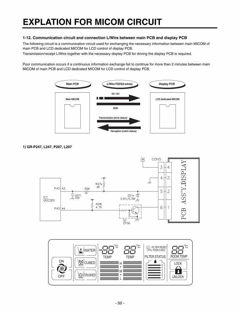
1-12. Communication circuit and connection L/Wire between main PCB and display PCBThe following circuit is a communication circuit used for exchanging the necessary information between main MICOM ofmain PCB and LCD dedicated MICOM for LCD control of display PCB.
Transmission/receipt L/Wire together with the necessary display PCB for driving the display PCB is required.
Poor communication occurs if a continuous information exchange fail to continue for more than 2 minutes between mainMICOM of main PCB and LCD dedicated MICOM for LCD control of display PCB.
1) GR-P247, L247, P207, L207
EXPLATION FOR MICOM CIRCUIT
- 50 -
ON
WATER
TEMP TEMP FILTER STATUS ROOM TEMP
LOCK
UNLOCK
654321
FILTER RESETPUSH 3 SEC
H
M
L
CUBED
CRUSHEDOFF
Main MICOM LCD dedicated MICOM
DC 12V
GND
Transmission (error status)
Reception (notch status)
Main PCB L/Wire FD/H(4-wires) Display PCB

2) GR-C247, B247, C207, B207
2. Sensor resistance characteristics table
u Resistance value allowance of sensor is ±5%. u In measuring resistance value allowance of sensor, perform measuring after leaving the sensor for more than 3 minutes
at the measuring temperature (delay is required due to sense speed relation relationship).u Since an analog tester has a large measuring temperature, measuring with a digital tester is required as possible as.u Resistance of the cold storage sensor 1 and 2 shall be measured with a digital tester after separating CON8 of the PWB
ASSY and the MAIN part. u Resistance of the freezing sensor shall be measured with a digital tester after separating CON7 of the PWB ASSY and
the MAIN part.
EXPLATION FOR MICOM CIRCUIT
- 51 -
Measuring Temperature (°C) Freezing Sensor Cold storage sensor 1, 2.
Frost removal sensor, Outside sensor
-20 °C 22.3 kΩ 77 kΩ
-15 °C 16.9 kΩ 60 kΩ
-15 °C 13.0 kΩ 47.3 kΩ
-5 °C 10.1 kΩ 38.4 kΩ
0 °C 7.8 kΩ 30 kΩ
+5 °C 6.2 kΩ 24.1 kΩ
+10 °C 4.9 kΩ 19.5 kΩ
+15 °C 3.9 kΩ 15.9 kΩ
+20 °C 3.1 kΩ 13 kΩ
+25 °C 2.5 kΩ 11 kΩ
+30 °C 2.0 kΩ 8.9 kΩ
+40 °C 1.4 kΩ 6.2 kΩ
+50 °C 0.8 kΩ 4.3 kΩ
TEMP
TEMP ROOM TEMP
UNLOCK

3. PWB parts diagram and list
3-1. PWB Ass’y, main part diagram1. GR-P247, L247, P207, L207
EXPLATION FOR MICOM CIRCUIT
- 52 -

2. GR-C247, B247, C207, B207
EXPLATION FOR MICOM CIRCUIT
- 53 -

3-2. Parts list1. GR-P247, L247, P207, L207
EXPLATION FOR MICOM CIRCUIT
- 54 -

EXPLATION FOR MICOM CIRCUIT
- 55 -

2. GR-C247, B247, C207, B207
EXPLATION FOR MICOM CIRCUIT
- 56 -

EXPLATION FOR MICOM CIRCUIT
- 57 -
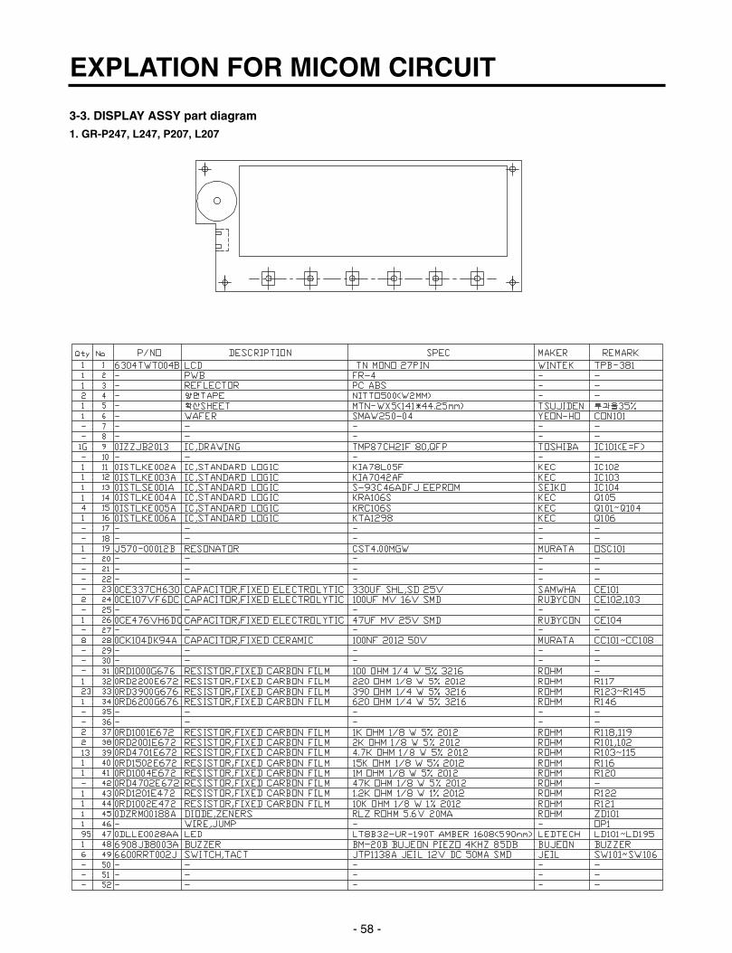
3-3. DISPLAY ASSY part diagram1. GR-P247, L247, P207, L207
EXPLATION FOR MICOM CIRCUIT
- 58 -
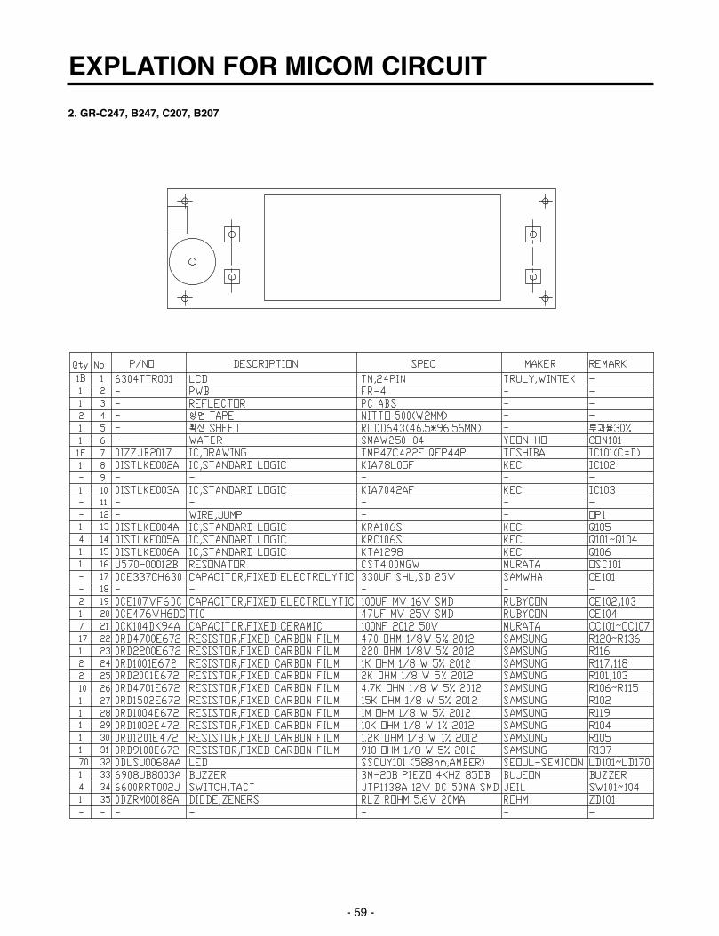
2. GR-C247, B247, C207, B207
EXPLATION FOR MICOM CIRCUIT
- 59 -

3-4. DISPLAY circuit diagram1. GR-P247, L247, P207, L207
- 60 -
Parts without ( ) mark means SMD parts.

2. GR-C247, B247, C207, B207
- 61 -
Parts without ( ) mark means SMD parts.
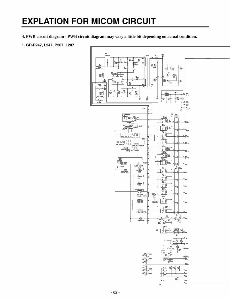
4. PWB circuit diagram - PWB circuit diagram may vary a little bit depending on actual condition.
1. GR-P247, L247, P207, L207
EXPLATION FOR MICOM CIRCUIT
- 62 -
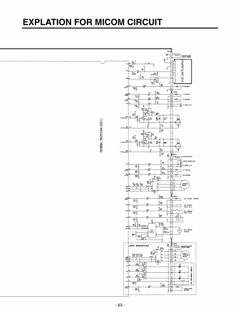
EXPLATION FOR MICOM CIRCUIT
- 63 -

2. GR-C247, B247, C207, B207
EXPLATION FOR MICOM CIRCUIT
- 64 -

EXPLATION FOR MICOM CIRCUIT
- 65 -
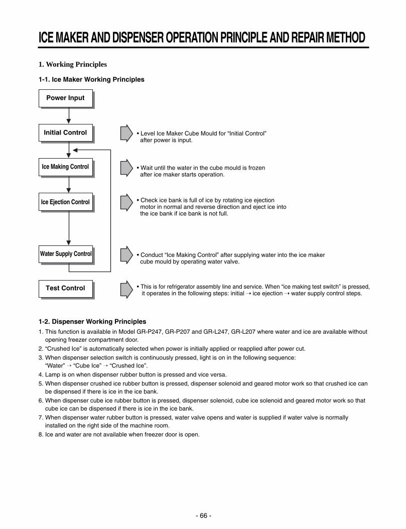
1. Working Principles
1-1. Ice Maker Working Principles
1-2. Dispenser Working Principles1. This function is available in Model GR-P247, GR-P207 and GR-L247, GR-L207 where water and ice are available without
opening freezer compartment door.
2. “Crushed Ice” is automatically selected when power is initially applied or reapplied after power cut.
3. When dispenser selection switch is continuously pressed, light is on in the following sequence: “Water” “Cube Ice” “Crushed Ice”.
4. Lamp is on when dispenser rubber button is pressed and vice versa.
5. When dispenser crushed ice rubber button is pressed, dispenser solenoid and geared motor work so that crushed ice canbe dispensed if there is ice in the ice bank.
6. When dispenser cube ice rubber button is pressed, dispenser solenoid, cube ice solenoid and geared motor work so thatcube ice can be dispensed if there is ice in the ice bank.
7. When dispenser water rubber button is pressed, water valve opens and water is supplied if water valve is normallyinstalled on the right side of the machine room.
8. Ice and water are not available when freezer door is open.
ICE MAKER AND DISPENSER OPERATION PRINCIPLE AND REPAIR METHOD
- 66 -
• Level Ice Maker Cube Mould for “Initial Control” after power is input.
Power Input
Initial Control
Ice Making Control
Ice Ejection Control
Water Supply Control
Test Control
• Wait until the water in the cube mould is frozen after ice maker starts operation.
• Check ice bank is full of ice by rotating ice ejection motor in normal and reverse direction and eject ice into the ice bank if ice bank is not full.
• This is for refrigerator assembly line and service. When “ice making test switch” is pressed, it operates in the following steps: initial ice ejection water supply control steps.
• Conduct “Ice Making Control” after supplying water into the ice maker cube mould by operating water valve.

2. Function of Ice Maker
2-1. Initial Control Function1. When power is initially applied or reapplied after power cut, it detects level of ice maker cube mould after completion of
MICOM initialization. The detecting lever moves up and down.
2. The level of ice maker cube mould is judged by output signal, high and low signal, of Hall IC. Make the cube mould to behorizontal by rotating ice ejection motor in normal or reverse direction so that High/Low signal can be applied to MICOMPin No. 42.
3. If there is no change in signals one minute after the geared motor starts to operate, it stops icemaker operation and checkthe signal every hour. It resets initialization of icemaker when it becomes normal.
4. It judges that the initial control is completed when it judges the ice maker cube mould is horizontal.
5. Ice ejection conducts for 1 cycle irrespect of ice in the ice bank when power is initially applied.
2-2. Water Supply Control Function1. This is to supply water into the ice maker cube mould by operating water valve in the machine room when ice ejection
control is completed and ice maker mould is even.
2. The quantity of water supplied is determined by DIP switch and time.
<Water Supply Quantity Table>
3. If water supply quantity setting is changed while power is on, water supplies for the amended time. If DIP switch ischanged during water supply, water shall be supplied for the previous setting time. But it will supply for the amended timefrom the next supply.
4. When water supply signal is applied to water and ice valves at the same time during water supply, water shall be suppliedto water valve. If water supply signal is applied to ice valve during water supply, water shall be supplied to both water andice valves.
2-3. Ice Making Control Function1. Ice making control is carried out from the completion of water supply to the completion of ice making in the cube mould.
Ice making sensor detects the temperature of cube mould and completes ice making. (ice making sensor is fixed belowice maker cube mould)
2. Ice making control starts after completion of water supply control or initial control.
3. It is judged that ice making is completed when ice making sensor temperature reaches at -8°C after 100 minutes whenwater is supplied to ice maker cube mould.
4. It is judged that ice making is completed when ice maker sensor temperature reaches below -12 °C after 20 minutes incondition 3.
ICE MAKER AND DISPENSER OPERATION PRINCIPLE AND REPAIR METHOD
- 67 -
DIP SWITCH SETTINGNoS/W 1 S/W 2 S/W 3
WATER SUPPLY TIME REMARKS
1 OFF OFF OFF 6.5 Sec.
2 ON OFF OFF 5.5 Sec.
3 OFF ON OFF 6 Sec.
4 ON ON OFF 7 Sec.
5 OFF OFF ON 7.5 Sec.
6 ON OFF ON 8 Sec.
7 OFF ON ON 9 Sec.
8 ON ON ON 10 Sec.
* The quantity of water supplieddepends on DIP switch settingconditions and water pressure as it isa direct tap water connection type.(the water supplied is generally 80 ccto 120 cc)
* DIP switch is on the main PWB.

2-4. Ice Ejection Control Function1. This is to eject ice from ice maker cube mould after ice making is completed.2. If Hall IC signal is on within 3.6 seconds after ice ejection motor rotates in normal direction, it does not proceed ice
ejection but waits. If the ice bank is full, ice ejection motor rotates in normal direction in every hour to check the conditionof ice bank. If the ice bank is not full, the water supply control starts after completion of ice ejection control. If the ice bankis full, ice ejection motor rotates in reverse direction and sops under ice making or waiting conditions.
3. If ice bank is not full, ice ejection starts. The cube mould tilts to the maximum and ice is separated from the mould and icechecking lever raises.
4. Ice ejection motor stops for 1 second if Hall IC signal changes from OFF (low) to ON (high) after 3.6 seconds when iceejection motor rotates in normal direction. If there is no change in Hall IC signals within 1 minute after ice ejection motoroperates, ice ejection motor stops as ice ejection motor or hall IC is out of order.
5. If ice ejection motor or Hall IC is abnormal, ice ejection motor rotates in normal direction to exercise initial operation. Itresets the ice maker if ice ejection motor or Hall IC is normal.
6. The mould stops for 1 second at maximum tilted conditions.7. The mould returns to horizontal conditions as ice ejection motor rotates in reverse direction.8. When the mould becomes horizontal, the cycle starts to repeat:
Water Supply Ice Making Ice Ejection Mould Returns to Horizontal
ICE MAKER AND DISPENSER OPERATION PRINCIPLE AND REPAIR METHOD
- 68 -
Bank is not full
HALL ICOUTPUTSIGNALS
Bank is full
HALL ICOUTPUTSIGNALS
ICE CHECKINGAXIS
ICE CHECKING LEVEL 30°
Maximum tiltingpoint
Ice making(Original point)
Lock
2±1 sec
9±3 sec
8±3 sec
Ice Checking Ice Ejection Lock
HorizontalConditions
Level RetrunConditions
<Timing Chart During Ice Ejection>

2-5 Test Function1. It is to force the operation during operation test, service, and cleaning. The test switch is mounted under the automatic
ice maker. The test function starts when the test switch is pressed for more than 0.5 second.2. Test button does not work during ice ejection and water supply. It works when it is in the horizontal conditions. If mould is
full of ice during test function operation, ice ejection control and water supply control do not work.3. When test switch is pressed for more than 0.5 second in the horizontal conditions, ice ejection starts irrespect of the
mould conditions. Water shall be splashed if test switch is pressed before the water in the mould freezes. Water shall besupplied while the mould returns to the horizontal conditions after ice ejection. Therefore the problems of ice ejection,returning to the horizontal conditions, and water supply can be checked by test switch. When test function performsnormally, buzzer sounds and water supply shall carry out. Check it for repair if buzzer does not sound.
4. When water supply is completed, the cycle operates normally as follows: Ice making Ice ejection Returning tohorizontal conditions Water supply
5. Remove ice from the ice maker cube mould and press test switch when ice maker cube mould is full of ice as ice ejectionand water supply control do not work when cube mould is full of ice.
2-6. Other functions relating to freezer compartment door opening1. When freezer door is open, ice dispenser stops in order to reduce noise and ice drop.
2. When freezer door is open during ice ejection and cube mould returning to horizontal condition, ice ejection and cubemould level return proceed.
3. When freezer door is open, geared motor and cube ice solenoid immediately stop and duct door solenoid stops after 5seconds.
4. Water dispenser stops in order to protect water drop when freezer door is open.
5. Test function operates normally irrespect of refrigearator compartment door opening.
ICE MAKER AND DISPENSER OPERATION PRINCIPLE AND REPAIR METHOD
- 69 -

3. Ice Maker Troubleshooting* Troubleshooting: it is possible to confirm by pressing freezer and refrigerator temperature control buttons for more
than 1 second. (ice maker is normal if all leds are on): refer to trouble diagnposis function in MICOMfunction 2-8 (page 18)
ICE MAKER AND DISPENSER OPERATION PRINCIPLE AND REPAIR METHOD
- 70 -
No
Yes
Yes
Yes
No
No
No
No
Yes
Yes
Is DC Power (5V and 12V) output normal?
Failed DC Power
• Check DC power (5V, 12V).
Change main PWB
Is cube ice LCD off duringtroubleshooting check? Failed ice making sensor
• Check the resistance of both ends (1,2) of ice making sensor of CON9.
• Defects between ice making sensor and board (Pin No. 60 of IC1)
Replace Ice makingSensor
Is Crushed Ice LCD off duringtroubleshooting check?
Failed Ice Maker Unit
• Is the resistance of both ends (9,10) of ice ejection motor of CON9 between 18 and 22Ω?
• Is ice ejection motor drive circuit(IC11 and peripheral circuits)normal?
• Defects between Hall IC and Board (Pin No. 42 of IC1).
• Confirm ice ejection and levelreturn when pressing test switch.
Replace Ice Maker Unit
Replace Main PWB
Are iceejection and level return
normal when test switch ispressed for more than 0.5 second?
Does the bell sound once?
Failed ice maker unit test switch
• Are both ends (5,6) of CON9 test switch open?
• Defects between test switchand board (Pin No. 38 of IC1).
• Are both ends (3,4) of CON9ice maker stop switch short?
Replace Ice maker Unit
Replace water supply valve
• Is power applied to water supply valve?
• Does the water supply valve work normally?
• Is the water supply line normally connected?
Poor water supplyIs water suppy normalafter Ice ejection and level return
by ice ejection motor?
Normal
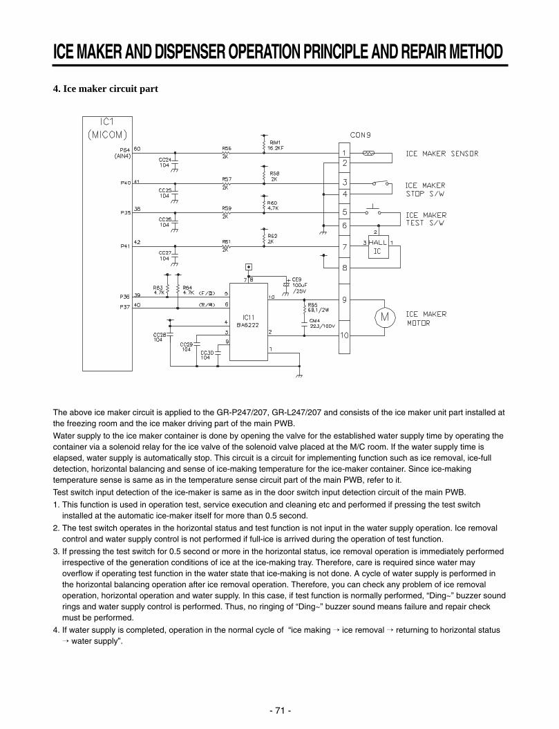
4. Ice maker circuit part
The above ice maker circuit is applied to the GR-P247/207, GR-L247/207 and consists of the ice maker unit part installed atthe freezing room and the ice maker driving part of the main PWB.
Water supply to the ice maker container is done by opening the valve for the established water supply time by operating thecontainer via a solenoid relay for the ice valve of the solenoid valve placed at the M/C room. If the water supply time iselapsed, water supply is automatically stop. This circuit is a circuit for implementing function such as ice removal, ice-fulldetection, horizontal balancing and sense of ice-making temperature for the ice-maker container. Since ice-makingtemperature sense is same as in the temperature sense circuit part of the main PWB, refer to it.
Test switch input detection of the ice-maker is same as in the door switch input detection circuit of the main PWB.
1. This function is used in operation test, service execution and cleaning etc and performed if pressing the test switchinstalled at the automatic ice-maker itself for more than 0.5 second.
2. The test switch operates in the horizontal status and test function is not input in the water supply operation. Ice removalcontrol and water supply control is not performed if full-ice is arrived during the operation of test function.
3. If pressing the test switch for 0.5 second or more in the horizontal status, ice removal operation is immediately performedirrespective of the generation conditions of ice at the ice-making tray. Therefore, care is required since water mayoverflow if operating test function in the water state that ice-making is not done. A cycle of water supply is performed inthe horizontal balancing operation after ice removal operation. Therefore, you can check any problem of ice removaloperation, horizontal operation and water supply. In this case, if test function is normally performed, “Ding~” buzzer soundrings and water supply control is performed. Thus, no ringing of “Ding~” buzzer sound means failure and repair checkmust be performed.
4. If water supply is completed, operation in the normal cycle of “ice making ice removal returning to horizontal status water supply”.
ICE MAKER AND DISPENSER OPERATION PRINCIPLE AND REPAIR METHOD
- 71 -
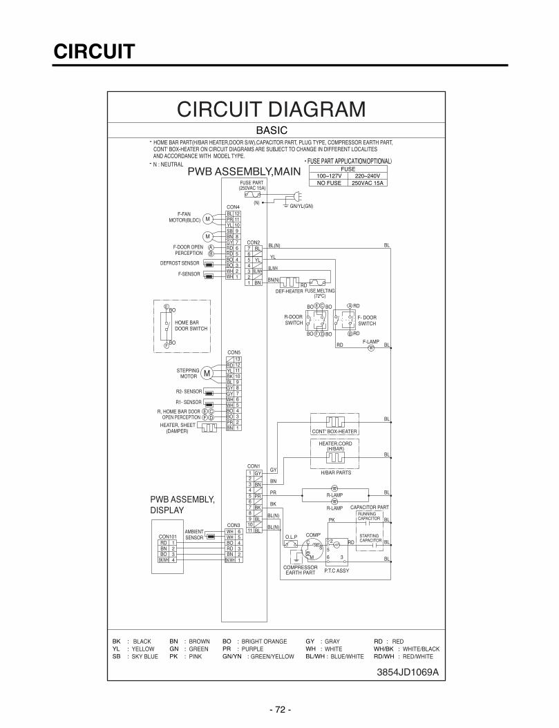
CIRCUIT
- 72 -
3854JD1069A

CIRCUIT
- 73 -
3854JD1069A

1. TROUBLE SHOOTING
TROUBLE DIAGNOSIS
- 74 -
CLAIMS. CAUSES AND CHECK POINTS. HOW TO CHECK
1. Faulty start1) No power on outlet.2) No power on cord.
3) Shorted start circuit.
4) During defrost.
* Measuring instrument :Multi tester
Check the voltage.If the voltage is within ±85%of the rated voltage, it is OK.
Check the terminalmovement.
Check both terminals ofpower cord.Power conducts : OK.No power conducts : NG
Check both terminals ofO.L.P.If power conducts : OK.If not : NG.
Check the resistance of bothterminals.At normal temperature 6 :OK.If disconnected : ∞.
Bad connection between adapter and outlet. (faulty adapter)The Inner diameter of adapter.The distance between holes.The distance between terminals.The thickness of terminal.
Bad connection between plug and adapter (faulty plug).The distance between pins.Pin outer diameter.
No power onpower cord.
O.L.P is off.
No electric power on compressor. - Faulty compressor.
Faulty PTC.
Disconnected copper wire.
Internal electrical short.
Faulty terminal contact.
Disconnected.
Capacity of O.L.P is small.
Characteristics of O.L.P is bad.
Bad connection.
Power is disconnected.
Inner Ni-Cr wire blows out.Bad internal connection.Faulty terminal caulking (Cu wire is cut).Bad soldering.
Weak connection.Short inserted cord length.Worn out tool blade.
Loose contact.- Large distance betweenmale terminal.
- Thin female terminal.
Terminal disconnected.
Bad sleeve assembly.
Power cord is disconnected.
Faulty soldering.
Start automatic defrost.Cycle was set at defrost when the refrigeratorwas produced.
Power does not conduct. - Damage.
Bad characteristics. - Initial resistance is big.
Bad connection withcompressor.
Bad terminal connection.
Too loose.Assembly is not possible.

TROUBLE DIAGNOSIS
- 75 -
CLAIMS. CAUSES AND CHECK POINTS. HOW TO CHECK
2. No cooling. 2) Refrigeration system is clogged. Check the cloggedevaporator by heating (assoon as the cracking soundbegins, the evaporator startfreezing)
The evaporator does not coolfrom the beginnig (no evideceof misture attached).The evaporator is the sameas before even heat isapplied.
Moistureclogged.
No electricpower ontherm-ostat.
Weld jointclogged.
Drier cloggeing.
Foreign material clogging.
Residual moisturein the evaporator.
Residual moisture.
Insufficient driercapacity.
Residual moisture in pipes.
Moisture penetration - Leave it in the air. - Moisture penetration.into the refrigeration oil.
Caps are missed.
Air blowing.
During transportation.During work.
Not performed.Performed.
Too short time.Low air pressure.Less dry air.
Air Blowing.
Leave it in the air.
Caps are missed.
Short pipe insert.
Pipe gaps.
Too much solder.
Too large.Damaged pipes.
Not dried in the compressor.Elapsed more than 6 months after dryingCaps are missed.No pressure when it is open.
During rest time.
After work.
Compressor cap is disconnected.Foreign materials are in the pipe.
Not performed.Too short.Impossible moistureconfirmation.Low air pressure.
Dry drier - Drier temperature.
Leave it in the air.
The capillary tube inserted depth. - Too much.
Capillary tube melts. - Over heat.
Clogged with foreign materials.
Reduced cross section by cutting. - Squeezed.
Desiccant powder.Weld oxides.Drier angle.
Check on packagecondition.Good storage afterfinishing.

TROUBLE DIAGNOSIS
- 76 -
CLAIMS. CAUSES AND CHECK POINTS. HOW TO CHECK
3. Refrigeration is weak.
Plateheater
Cordheater
1) Refrigerant Partly leaked.
2) Poor defrosting capacity.
Drain path (pipe) clogged.
Defrost heater does not generate heat.
Weld joint leak.Parts leak.
Inject P/U into drain hose.
Foreign materialspenetration.
Cap drain is not disconnected.
Inject through thehole.Seal with drain.
P/U lump input.Screw input.Other foreign materialsinput.
Parts disconnected.
Wire is cut.- Heating wire.- Contact pointbetween heatingand electric wire.
Dent by fin evaporator.Poor terminal contacts.
Wire is cut.- Lead wire.- Heating wire.- Contact pointbetween heating andelectric wire.
Heating wire is corroded- Water penetration.Bad terminal connection.
Check visually.
Check terminal Conduction: OK.No conduction: NG.If wire is not cut, refer toresistance.P=PowerV=VoltageR=Resistance
V2P= —
R
V2R= —
P

- 77 -
TROUBLE DIAGNOSIS
CLAIMS. CAUSES AND CHECK POINTS. HOW TO CHECK
3. Refrigeration is weak.
3) Cooling air leak.
4) No cooling air circulation.
Residualfrost.
No automatic defrosting.
Defrost does not return.
Bad gasket adhestion
Door sag.
Faulty fan motor.
Weak heat from heater.
Bad heater assembly.
Too short defrosting time. Defrost Sensor.
- Faulty characteristics.
Seat-D(missing, location. thickness).
Structural fault. Gasket gap.
Air inflow through the fan motor.
Bad insulation of case door.
Sheath Heater - rated.Heater plate - rated.Heater cord-L - rated.
Heater plate
Heater cord-L
Gap.Bad attachment.Contraction.
Bad adhesion.Weak binding force at hinge.
Fan motor.
Door switch.
Self locked.Wire is cut.Bad terminal contact.
Contact distance.Button pressure.Melted contact.Contact.
Poor doorattachment.Door liner(dimension).Contraction innerliner.Misalignment.Bad terminalconnection.P/U liquid leak.
Faults.
Refrigerator and freezer switch reversed.Button is not pressed.
No contact to drain.Loosened stopper cord.
Not contact to theevaporator pipe.Location of assembly(top and middle).
Check the fan motorconduction: OK.No conduction: NG.

TROUBLE DIAGNOSIS
- 78 -
CLAIMS. CAUSES AND CHECK POINTS. HOW TO CHECK
3. Refrigeration is weak.
4) No cooling air circulation.
5) Compressor capacity.
6) Refrigerant too much or too little.
7) Continuous operation- No contact of temperature controller. - Foreign materials.
8) Damper opens continuously.Foreign materials jammed.
Failed sensor. - Position of sensor.Characteristics of damper.
9) Food storing place. - Near the outlet of cooling air.
Faulty fan motor.
Small cooling airdischarge.
Fan is constrained.
Insufficientmotor RPM
Faulty fan.
Shorud. Bent.
Ice and foreign materials on rotating parts.
Fan shroud contact. - Clearance.Damping evaporator contact.Accumulated residual frost.
Fan misuse.Bad shape.Loose connection. - Not tightly connected.Insert depth.
Rating misuse.Small capacity.Low valtage.
Malfunction of charging cylinder.Wrong setting of refrigerant.Insufficient compressor. - Faulty compressor.
Fan overload. - Fan misuse.Bad low termperature RPM characteristics.Rated power misuse.Low voltage.
P/U liquid dump.EPS water sediment.Screw.
Bad characteristics of its own temperatue.Parts misuse.Charge of temperature - Impact.characteristics.
Check visually afterdisassembly.
Check visually afterdisassembly.
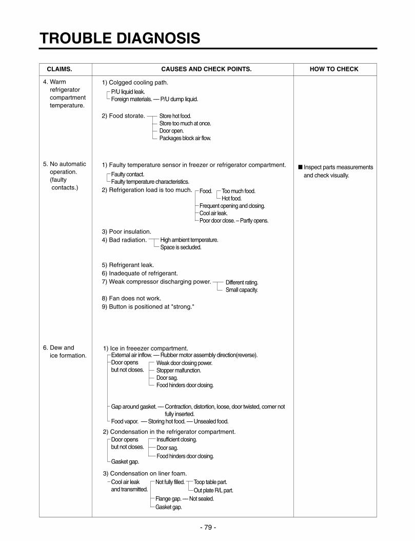
TROUBLE DIAGNOSIS
- 79 -
CLAIMS. CAUSES AND CHECK POINTS. HOW TO CHECK
4. Warmrefrigeratorcompartmenttemperature.
5. No automaticoperation.(faulty contacts.)
6. Dew and ice formation.
1) Colgged cooling path.
2) Food storate.
1) Faulty temperature sensor in freezer or refrigerator compartment.
2) Refrigeration load is too much.
3) Poor insulation.4) Bad radiation.
5) Refrigerant leak.6) Inadequate of refrigerant.7) Weak compressor discharging power.
8) Fan does not work.9) Button is positioned at "strong."
1) Ice in freeezer compartment.
2) Condensation in the refrigerator compartment.
3) Condensation on liner foam.
P/U liquid leak.Foreign materials. –– P/U dump liquid.
Faulty contact.Faulty temperature characteristics.
External air inflow. –– Rubber motor assembly direction(reverse).Door opens but not closes.
Gap around gasket. –– Contraction, distortion, loose, door twisted, corner notfully inserted.
Food vapor. –– Storing hot food. –– Unsealed food.
Door opensbut not closes.
Gasket gap.
Cool air leakand transmitted.
High ambient temperature.Space is secluded.
Different rating.Small capacity.
Store hot food.Store too much at once.Door open.Packages block air flow.
Food.
Frequent opening and closing.Cool air leak.Poor door close. – Partly opens.
Too much food.Hot food.
Weak door closing power.Stopper malfunction.Door sag.Food hinders door closing.
Insufficient closing.Door sag.Food hinders door closing.
Toop table part.Out plate R/L part.
Not fully filled.
Flange gap. –– Not sealed.Gasket gap.
Inspect parts measurementsand check visually.
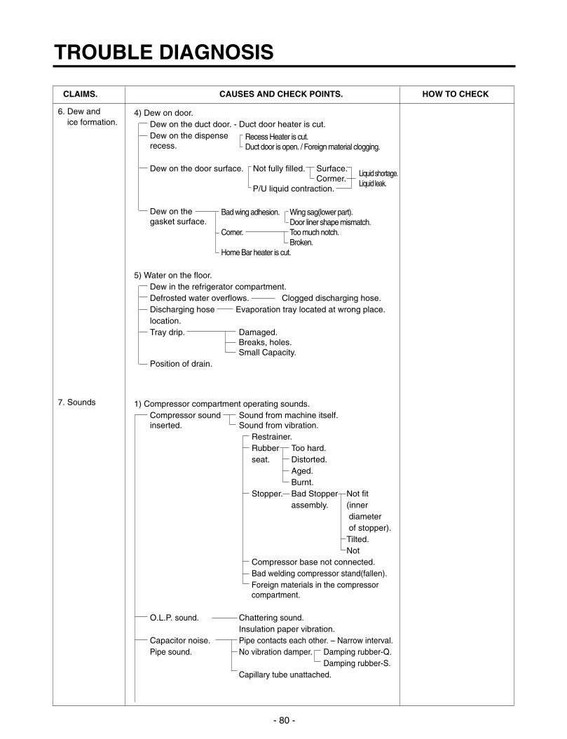
TROUBLE DIAGNOSIS
- 80 -
CLAIMS. CAUSES AND CHECK POINTS. HOW TO CHECK
6. Dew and ice formation.
7. Sounds
4) Dew on door.Dew on the duct door. - Duct door heater is cut.Dew on the dispense recess.
Dew on the door surface. Not fully filled. Surface.Cormer.
P/U liquid contraction.
Dew on thegasket surface.
5) Water on the floor.Dew in the refrigerator compartment.Defrosted water overflows. Clogged discharging hose.Discharging hose Evaporation tray located at wrong place.location.Tray drip. Damaged.
Breaks, holes.Small Capacity.
Position of drain.
1) Compressor compartment operating sounds.Compressor sound Sound from machine itself.inserted. Sound from vibration.
Restrainer.Rubber Too hard.seat. Distorted.
Aged.Burnt.
Stopper. Bad Stopper Not fitassembly. (inner
diameterof stopper).Tilted.Not
Compressor base not connected.Bad welding compressor stand(fallen).Foreign materials in the compressor compartment.
O.L.P. sound. Chattering sound.Insulation paper vibration.
Capacitor noise. Pipe contacts each other. – Narrow interval.Pipe sound. No vibration damper. Damping rubber-Q.
Damping rubber-S.Capillary tube unattached.
Recess Heater is cut.Duct door is open. / Foreign material clogging.
Bad wing adhesion. Wing sag(lower part).Door liner shape mismatch.
Corner. Too much notch.Broken.
Home Bar heater is cut.
Liquid shortage.Liquid leak.

TROUBLE DIAGNOSIS
- 81 -
CLAIMS. CAUSES AND CHECK POINTS. HOW TO CHECK
7. Sounds 1) Compressor compartment operating sounds.Transformer sound.
Drip tray vibration sound.
Back cover machine sound.
Condenser drain sound.
2) Freezer compartment sounds.Fan motor sound.
Sounds from fancontact.
Unbalance fan sounds.
Motor shaftcontact sounds.
Resonance.Evaporator noise.
3) Bowls and bottles make contact on top shelf.
4) Refrigerator roof contact.
5) Refrigerator side contact.
6) Insufficient Lubricants on door hinge.
Its own fault. –– Core gap.Bad connection. –– Correct screw connection.
Bad assembly.Distortion.Foreign materials inside.
Bad connection.Partly damaged.
Not connected.Bad pipe caulking.
Normal operating sound.Vibration sound. Aged rubber seat.
Bad torque for assembling motorbracket.
Fan guide contact.Shroud burr contact.Damping evaporator contact.Residual frost contact.
Unbalance.
Ice on the fan. –– Air intake (opposite to motorrubber assembly.)
Supporter disorted.Tilted during motor assembly.
Evaporator pipe contact. –– No damping evaporator.Sound from refrigerant. –– Stainless steel pipe shape in
accumulator.Sound from fin evaporator and pipe during expansionand contraction.
Poor treatment Cord heater.Narrow evaporator interval.
Surface machining conditions.Fan distortion.Misshappen.Burr.

TROUBLE DIAGNOSIS
- 82 -
CLAIMS. CAUSES AND CHECK POINTS. HOW TO CHECK
8. Faulty lamp(freezer andrefrigeratorcompartment).
9. Faulty internal voltage(short).
1) Lamp problem. Filament blows out.Glass is broken.
2) Bad lamp assembly. Not inserted.Loosened by vibration.
3) Bad lamp socket.Disconnection. Bad soldering.
Bad rivet contact.Short. Water penetration. Low water
level in tray.
Bad elasticity of contact.Bad contact(corrosion).
4) Door switch. Its own defect.Refrigerator and freezer switch is reversed.Travlel distance.Bad connection.Bad terminal contact.P/U liquid leak..
1) Lead wire is damaged.Wire damage when assembling P.T.C. Cover.Outlet burr in the bottom plate.Pressed by cord heater. lead wire, evaporator pipe.
2) Exposed terminal.Compressor Compartment terminal. - Touching other
components.Freezer compartment terminal. - Touching evaporator pipe.
3) Faulty parts.Transformer. Coil contacts cover.
Welded terminal parts contact cover.Compressor. Bad coil insulation.Plate heater.Melting fuse. Sealing is broken. Moisture penetration.Cord heater. Pipe damaged. Moisture penetration.
Bad sealing.Sheath heater.
Connect conduction andnon-conduction parts andcheck with tester. Conduction: NG.Resistance∞: OK.
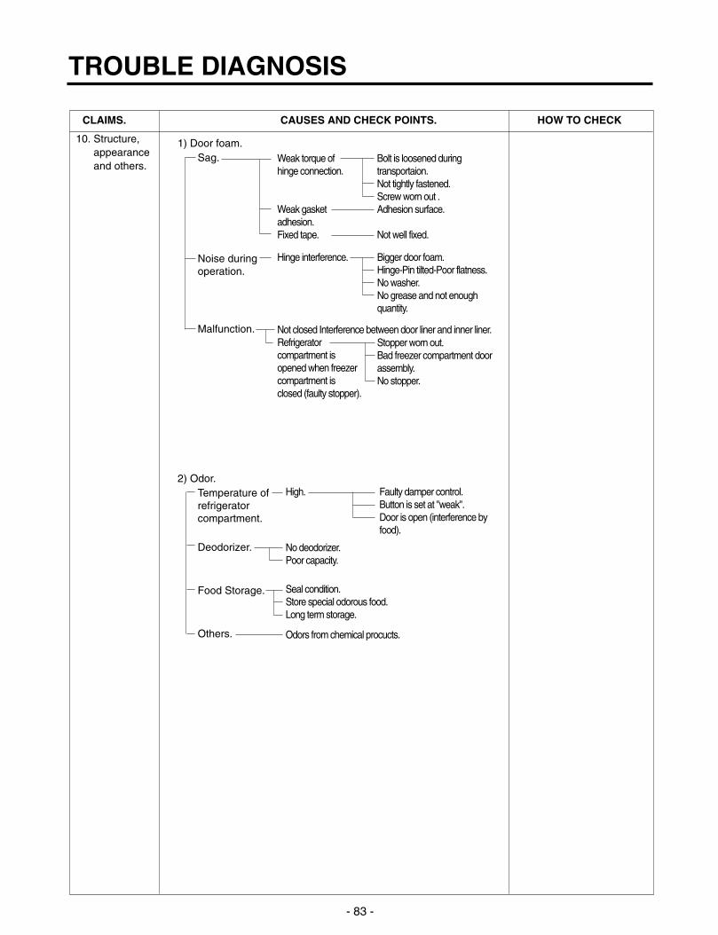
TROUBLE DIAGNOSIS
- 83 -
CLAIMS. CAUSES AND CHECK POINTS. HOW TO CHECK
10. Structure, appearanceand others.
1) Door foam.Sag.
Noise duringoperation.
Malfunction.
2) Odor.Temperature of refrigeratorcompartment.
Deodorizer.
Food Storage.
Others.
Weak torque ofhinge connection.
Weak gasketadhesion.Fixed tape.
Hinge interference.
Not closed Interference between door liner and inner liner.Refrigeratorcompartment is opened when freezercompartment is closed (faulty stopper).
High. Faulty damper control.Button is set at "weak".Door is open (interference byfood).
No deodorizer.Poor capacity.
Seal condition.Store special odorous food.Long term storage.
Odors from chemical procucts.
Bigger door foam.Hinge-Pin tilted-Poor flatness.No washer.No grease and not enoughquantity.
Stopper worn out.Bad freezer compartment doorassembly.No stopper.
Bolt is loosened duringtransportaion.Not tightly fastened.Screw worn out .Adhesion surface.
Not well fixed.

2. F
ault
s
2-1.
Po
wer
2-2.
Co
mp
ress
or
TROUBLE DIAGNOSIS
- 84 -
Pro
ble
ms
Cau
ses
Ch
ecks
Mea
sure
sR
emar
ks
No
pow
er o
n -
Pow
er c
ord
cut.
- C
heck
the
volta
ge w
ith te
ster
.-R
epla
ce th
e co
mpo
nent
s.
outle
t.-
Fau
lty c
onne
ctor
inse
rtio
n.-
Che
ck v
isua
lly.
-Rec
onne
ct th
e co
nnec
ting
part
s.
- F
aulty
con
nect
ion
betw
een
plug
- C
heck
vis
ually
.-
Rec
onne
ct th
e co
nnec
ting
part
s.
and
adap
ter.
Fus
e bl
ows
out.
- S
hort
circ
uit b
y w
rong
con
nect
ion.
- C
heck
the
fuse
with
test
er-
Fin
d an
d re
mov
e th
e ca
use
of
- R
epla
ce w
ith r
ated
- Lo
w v
olta
ge p
rodu
cts
are
or v
isua
lly.
prob
lem
(ex.
sho
rt, h
igh
volta
ge,
fuse
afte
r co
nfirm
ing
conn
ecte
d to
hig
h vo
ltage
.-
Che
ck th
e in
put v
olt a
re w
ith te
ster
low
vol
tage
).
its s
peci
ficat
ion.
- S
hort
circ
uit b
y in
sect
s.(b
etw
een
pow
er c
ord
and
prod
ucts
).-
Rep
lace
with
rat
ed fu
se.
- E
lect
ricity
leak
age.
- C
heck
the
resi
stan
ce o
f pow
er c
ord
If
fuse
blo
wns
out
- H
igh
volta
ge.
with
test
erf (
if it
is 0
Ω, i
t is
shor
ted)
.fr
eque
ntly
, rec
onfir
m
- S
hort
circ
uit o
f com
pone
nts
the
caus
e an
d pr
even
t.
(tra
ckin
g du
e to
moi
stur
e an
d du
st
pene
trat
ion)
.
Pro
ble
ms
Cau
ses
Ch
ecks
Mea
sure
sR
emar
ks
Com
pres
sor
- F
aulty
PT
C.
- C
heck
the
resi
stan
ce.
- If
resi
stan
ce is
infin
ite, r
epla
ce it
does
not
V
laue
:∞is
def
ectiv
e.w
ith n
ew o
ne.
oper
ate.
- If
it is
not
infin
ite, i
t is
norm
al.
- C
heck
oth
er p
arts
.
- C
ompr
esso
r is
froz
en.
- If
com
pres
sor
asse
mbl
y pa
rts
are
- D
urin
g fo
rced
ope
ratio
n:
norm
al(c
apac
itor,
PT
C, O
LP),
-
Ope
rate
s: C
heck
oth
er p
arts
.
appl
y po
wer
dire
ctly
to th
e -
Not
ope
rate
: Rep
lace
the
froz
en
com
pres
sor
to fo
rce
oper
atio
n.co
mpr
esso
r w
ith n
ew o
ne, w
eld,
evac
uate
, and
rec
harg
e re
frig
eran
t.
OLP
It
sta
rts
as s
oon
as it
is•
Ref
er to
wel
d re
pair
proc
edur
es.
cont
acte
d.
Aux
iliar
y w
indi
ng
Mai
n w
indi
ng
Pow
er

2-3.
Tem
per
atu
re
TROUBLE DIAGNOSIS
- 85 -
Pro
ble
ms
Cau
ses
Ch
ecks
Mea
sure
sR
emar
ks
Hig
h P
oor
cool
air
circ
ulat
ion
due
to fa
ulty
- Lo
ck –
– C
heck
res
ista
nce
with
a
- R
epla
ce fa
n m
otor
.
tem
pera
ture
fan
mot
or.
test
er.
in th
e fr
eeze
r0Ω
: sho
rt.
com
part
men
t.∞
Ω: c
ut.
- R
econ
nect
and
rei
nser
t.
- R
otat
e ro
tor
man
ually
and
che
ck
rota
tion.
- W
ire is
cut
.
- B
ad te
rmin
al c
onta
ct: C
heck
-
Mai
ntai
n cl
eara
nce
and
rem
ove
ice
term
inal
vis
ually
.(R
epai
r an
d/or
rep
lace
shr
oud
if fa
n
- F
an c
onst
rain
t. –
Fan
shr
oud
is c
onst
rain
ed b
y sh
roud
cont
act:
Con
firm
defo
rmat
ion)
.
visu
ally
.
– F
an ic
ing:
Con
firm
vis
ually
.
Fau
lty fa
n m
otor
due
to fa
ulty
doo
r -
Iced
but
ton
(fau
lty)
oper
atio
n:-
Con
firm
icin
g ca
uses
and
rep
air.
switc
h op
erat
ion.
Pre
ss b
utto
n to
che
ck-
Rep
lace
doo
r sw
itch.
- F
aulty
but
ton
pres
sure
and
con
tact
:
Pre
ss b
utto
n to
che
ck o
pera
tion.
- D
oor
cann
ot p
ress
doo
r sw
itch
- D
oor
sag:
fix
door
.
butto
n: C
heck
vis
ually
.-
Doo
r lin
er b
ent:r
epla
ce d
oor
or
atta
ch s
heet
s.
Bad
rad
iatio
n co
nditi
ons
in
- C
heck
the
clea
ranc
e be
twee
n th
e -
Kee
p cl
eara
nce
betw
een
- T
he fa
n m
ay b
e
com
pres
sor
com
part
men
t.re
frig
erat
or a
nd w
all (
50 m
m in
re
frig
erat
or a
nd w
alls
(m
inim
um
brok
en if
cle
anin
g
min
imum
).50
mm
).pe
rfor
ms
whi
le th
e
- C
heck
dus
t on
the
grill
in
- R
emov
e du
st a
nd c
onta
min
ants
re
frig
erat
or is
on.
com
pres
sor
com
part
men
t.fr
om g
rill f
or e
asy
heat
rad
iatio
n.
- C
heck
dus
t on
the
coils
con
dens
er.
- R
emov
e th
e du
st w
ith v
acuu
m
clea
ner
from
the
coils
con
dens
er
whi
le th
e re
frig
erat
or is
off.
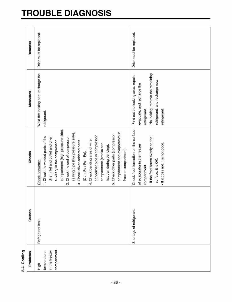
2-4.
Co
olin
g
TROUBLE DIAGNOSIS
- 86 -
Pro
ble
ms
Cau
ses
Ch
ecks
Mea
sure
sR
emar
ks
Hig
h R
efrig
eran
t lea
k.C
heck
seq
uenc
eW
eld
the
leak
ing
part
, rec
harg
e th
eD
rier
mus
t be
repl
aced
.
tem
pera
ture
1. C
heck
the
wel
ded
part
s of
the
refr
iger
ant.
in th
e fr
eeze
rdr
ier
inle
t and
out
let a
nd d
rier
com
part
men
t.au
xilia
ry in
the
com
pres
sor
com
part
men
t (hi
gh p
ress
ure
side
).
2. C
heck
the
end
of c
ompr
esso
r
seal
ing
pipe
(lo
w p
ress
ure
side
).
3. C
heck
silv
er s
olde
red
part
s.
(Cu
+ F
e / F
e +
Fe)
.
4. C
heck
ben
ding
are
a of
wire
cond
ense
r pi
pe in
com
pres
sor
com
part
men
t (cr
acks
can
happ
en d
urin
g be
ndin
g).
5. C
heck
oth
er p
arts
(co
mpr
esso
r
com
part
men
t and
eva
pora
tors
in
free
zer
com
part
men
t).
Sho
rtag
e of
ref
riger
ant.
Che
ck fr
ost f
orm
atio
n on
the
surf
ace
- F
ind
out t
he le
akin
g ar
ea, r
epai
r,D
rier
mus
t be
repl
aced
.
of e
vapo
rato
r in
the
free
zer
evac
uate
, and
rec
harg
e th
e
com
part
men
t.re
frig
eran
t.
- If
the
fros
t for
ms
even
ly o
n th
e -
No
leak
ing,
rem
ove
the
rem
aini
ng
surf
ace,
it is
OK
.re
frig
eran
t, an
d re
char
ge n
ew
- If
it do
es n
ot, i
t is
not g
ood.
refr
iger
ant.

TROUBLE DIAGNOSIS
- 87 -
Pro
ble
ms
Cau
ses
Ch
ecks
Mea
sure
sR
emar
ks
Hig
h C
ycle
pip
e is
clo
gged
.C
heck
seq
uenc
e.-
Hea
t up
com
pres
sor
disc
harg
ing
Dire
r m
ust b
e re
plac
ed.
tem
pera
ture
in1.
Che
ck te
mpe
ratu
re o
f con
dens
erw
eld
join
ts w
ith to
uch,
dis
conn
ect
the
free
zer
man
ually
.th
e pi
pes,
and
che
ck th
e cl
oggi
ng.
com
part
men
t.If
it is
war
m, i
t is
OK
.R
emov
e th
e ca
uses
of c
logg
ing,
If it
is n
ot, c
ompr
esso
r di
scha
rgin
gw
eld,
eva
cuat
e, a
nd r
echa
rge
join
ts m
ight
be
clog
ged.
the
refr
iger
ant.
2. M
anua
lly c
heck
whe
ther
hot
line
- If
it's
war
m, i
t's O
K. I
f it's
not
,
pipe
is w
arm
.co
nden
ser
disc
harg
ing
line
wel
d
If it
is w
arm
, it's
OK
.jo
ints
mig
ht b
e cl
ogge
d.
If it
is n
ot, c
onde
nser
out
let w
eld
Dis
conn
ect w
ith to
rch,
rem
ove
the
join
ts m
ight
be
colg
ged.
caus
es, e
vacu
ate,
and
rec
harg
e
seal
ref
riger
ant.
Leak
at l
oop
pipe
wel
d jo
int
Che
ck s
eque
nce.
Rep
lace
the
com
pres
sor,
wel
d,
Drie
r m
ust b
e re
plac
ed.
(dis
char
ge)
in c
ompr
esso
r.1.
Man
ually
che
ck w
heth
er
evac
uate
, and
rec
harg
e re
frig
eran
t.
cond
ense
r is
war
m, I
t is
not w
arm
and
the
fros
t for
ms
part
ly o
n th
e
evap
orat
or in
the
free
zer
com
part
men
t.
Fau
lty c
oolin
g fa
n in
the
com
pres
sor
Che
ck s
eque
nce.
- R
epla
ce if
mot
or d
oes
not o
pera
te.
com
part
men
t.1.
Che
ck c
oolin
g fa
n op
erat
ion.
- If
fan
is d
isco
nnec
ted,
che
ck fa
n
2. C
heck
that
coo
ling
fan
is
dam
age
and
reas
sem
ble
it.
disc
onne
cted
from
the
mot
or.
R
efer
to fa
n m
otor
dis
asse
mbl
y
and
asse
mbl
y se
quen
ce.

2-5.
Def
rost
ing
fai
lure
TROUBLE DIAGNOSIS
- 88 -
Pro
ble
ms
Cau
ses
Ch
ecks
Mea
sure
sR
emar
ks
No
defr
ostin
g.H
eate
r do
es n
ot g
ener
ate
heat
as
1. C
heck
the
resi
stan
ce o
f hea
ter.
Hea
ting
wire
is s
hort
and
wire
is c
ut.
Sea
l the
lead
wire
with
the
heat
ing
wire
is c
ut o
r th
e ci
rcui
t0Ω
: Sho
rt. ∞
Ω: C
ut.
• P
arts
rep
lace
men
t: R
efer
to p
arts
insu
latio
n ta
pe a
nd h
eat
is s
hort
ed.
Ten
s to
thou
sand
s Ω
: OK
.ex
plan
atio
ns.
cont
ract
ion
tube
if th
e cu
t
1) H
eatin
g w
ire is
dam
aged
whe
n 2.
Che
ck th
e re
sist
ance
bet
wee
n le
ad w
ire is
acc
essi
ble
to
inse
rtin
g in
to th
e ev
apor
ator
.ho
usin
g te
rmin
al a
nd h
eate
rre
pair.
2) L
ead
wire
of h
eate
r is
cut
.su
rfac
e.
3) H
eatin
g w
ire a
t lea
d w
ire c
onta
cts
0Ω: S
hort
. ∞Ω
: Cut
.
is c
ut.
Ten
s to
thou
sand
s Ω
: Sho
rt.
Suc
king
duc
t and
dis
char
ging
hol
e 1.
Con
firm
fore
ign
mat
eria
ls. I
n ca
se1)
Pus
h ou
t im
purit
ies
by in
sert
ing
are
clog
ged:
of ic
e, in
sert
the
copp
er li
ne
copp
er w
ire.(
Tur
n of
f mor
e th
an
1. Im
purit
ies.
thro
ugh
the
hole
to c
heck
.3h
ours
and
pou
r in
hot
wat
er if
2. Ic
e.2.
Put
hot
wat
er in
to th
e dr
ain
fros
t is
seve
re.)
(che
ck d
rain
s ou
tsid
e).
2) P
ut in
hot
wat
er to
mel
t dow
n fr
ost.
3) C
heck
the
wat
er o
utle
t.
4) P
ush
the
heat
er p
late
to s
ucki
ng
duct
man
ually
and
ass
embl
e th
e
disc
onne
cted
par
ts.
Gap
bet
wee
n S
ucki
ng d
uct a
nd1.
Con
firm
in th
e S
ucki
ng d
uct.
1) T
urn
off t
he p
ower
, con
firm
Hea
ter
plat
e(Ic
e in
the
gap)
.im
purit
ies
and
ice
in th
e ga
p, a
nd
supp
ly h
ot w
ater
unt
il th
e ic
e in
the
gap
mel
ts d
own.
2) P
ush
the
Hea
ter
plat
e to
dra
in
botto
m w
ith h
and
and
asse
mbl
e
the
disc
onne
cted
par
ts.
Wro
ng h
eate
r ra
ting
(or
wro
ng
1. C
heck
hea
ter
labe
l.F
aults
:rep
lace
.
asse
mbl
y).
2. C
onfir
m th
e ca
paci
ty a
fter
- H
ow to
rep
lace
: Ref
er to
mai
n pa
rts.
subs
titut
ing
the
resi
stan
ce v
alue
into
the
form
ula.
(V: R
ated
vol
tage
of u
ser c
ount
ry)
(R: R
esis
tanc
e of
test
er[Ω
])
Com
pare
P a
nd la
vel c
apac
ity.
Tole
ranc
e: ±
7%
V2
P=
–– R

TROUBLE DIAGNOSIS
- 89 -
Pro
ble
ms
Cau
ses
Ch
ecks
Mea
sure
sR
emar
ks
No
defr
ostin
gM
eltin
g fu
se b
low
s ou
t.-
Che
ck m
eltin
g fu
se w
ith te
ster
. -
Fau
llty
part
s: p
arts
rep
lace
men
t.
1) L
ead
wire
is c
ut.
If 0Ω
: OK
.-
Che
ck w
ire c
olor
whe
n m
aeas
urin
g
2) B
ad s
olde
ring.
If ∞
Ω: w
ire is
cut
.re
sist
ance
with
a te
ster
.
Ice
in th
e S
ucki
ng d
uct.
1. C
heck
the
inne
r du
ct w
ith m
irror
.1)
Tur
n po
wer
off.
1) Ic
ing
by fo
reig
n m
ater
ials
in th
e2)
Rai
se th
e fr
ont s
ide(
door
sid
e),
duct
.su
ppor
t the
fron
t sid
e le
gs, a
nd le
t
2) Ic
ing
by c
ool a
ir in
flow
thro
ugh
the
ice
mel
t nat
ural
ly. (
If po
wer
is
the
gap
of h
eate
r pl
ate.
on, m
elt t
he fr
ost b
y fo
rced
3) Ic
ing
by th
e ga
p of
hea
ter
plat
e.de
fros
ting.
)
2. C
heck
by
inse
rtin
g so
ft co
pper
3)
Rea
ssem
ble
the
heat
er p
late
.
wire
into
the
duct
(so
ft an
d th
in
copp
er n
ot to
impa
ir he
atin
g w
ire).
Bad
coo
l air
inflo
w a
nd d
isch
arge
, 1.
Tur
n on
pow
er, o
pen
or c
lose
the
1) C
heck
the
faul
ty c
onne
ctor
of
and
bad
defr
ostin
g du
e to
faul
tydo
or, c
heck
that
mot
or fa
n ho
usin
g an
d re
asse
mbl
e w
rong
ly
cont
act a
nd in
sert
ion
(bad
con
nect
orop
erat
es (
If it
oper
ates
, mot
or fa
nas
sem
bled
par
ts.
inse
rtio
n in
to h
ousi
ng o
f hea
ter,
is
OK
).2)
If th
e pa
rts
are
very
dam
aged
,
mel
ting,
fuse
and
mot
or fa
n).
2. D
isco
nnec
t par
ts in
the
refr
iger
ator
rem
ove
the
part
s an
d re
plac
e it
com
part
men
t, ch
eck
the
conn
ectio
nw
ith a
new
one
.
arou
nd th
e ho
usin
g vi
sual
ly,
defr
ost,
and
conf
irm h
eat g
ener
atio
n
on th
e he
ater
. Do
not p
ut h
ands
on
the
shea
th h
eate
r.
3. C
heck
the
part
s w
hich
hav
e fa
ults
desc
ribed
in 1
, 2 (
mec
hani
cal
mod
el: d
isco
nnec
t the
rmos
tat
from
the
asse
mbl
y).

2-6.
Icin
g
TROUBLE DIAGNOSIS
- 90 -
Pro
ble
ms
Cau
ses
Ch
ecks
Mea
sure
sR
emar
ks
Icin
g in
the
1) B
ad c
ircul
atio
n of
coo
l air.
- C
heck
the
food
is s
tore
d pr
oper
ly-
Be
acqu
aint
ed w
ith h
ow to
use
.-
Che
ck th
e de
fros
t
refr
iger
ator
-
Clo
gged
inta
ke p
ort i
n th
e (c
heck
dis
char
ge a
nd in
take
por
t -
Sea
ling
on c
onne
ctin
g pa
rts.
rela
ted
part
s if
prob
lem
com
part
men
t.re
frig
erat
or c
ompa
rtm
ent.
are
clog
ged)
.-
Che
ck th
e da
mpe
r an
d re
plac
eis
cau
sed
by fa
ulty
- D
ampe
r ic
ing.
- S
ealin
g is
not
goo
d.-
Che
ck ic
ing
on th
e su
rfac
e of
it
if it
has
defe
cts.
defr
ostin
g.
- P
ipe
icin
g.-
Too
muc
h fo
od is
sto
red
and
clog
sba
ffle
and
cool
air
path
(pi
pe)
afte
r-
Che
ck d
efro
st. (
Afte
r fo
rced
- D
isch
argi
ngth
e di
scha
rge
port
.di
ssem
blin
g th
e co
ntai
ner
box.
defr
ostin
g, c
heck
ice
in th
e
pipe
icin
g.-
Bad
def
rost
ing.
- C
heck
icin
g at
inta
ke p
orts
of
evap
orat
or a
nd p
ipes
.)
free
zer
and
refr
iger
ator
com
part
men
t.
2) F
aulty
doo
r or
ref
riger
ator
- C
heck
gas
ket a
ttach
ed c
ondi
tions
.-
Cor
rect
the
gask
et a
ttach
men
t-
Rep
lace
men
t sho
uld
com
part
men
t.-
Che
ck d
oor
asse
mbl
y co
nditi
ons.
cond
ition
s an
d re
plac
e it.
be d
one
whe
n it
- F
aulty
gas
ket.
- D
oor
asse
mbl
y an
d re
plac
emen
t.ca
nnot
be
repa
ired.
- F
aulty
ass
embl
y.
3) O
verc
oolin
g in
the
refr
iger
ator
- C
heck
ref
riger
ator
com
part
men
t-
Rep
lace
faul
ty p
arts
.
com
part
men
t.is
ove
rcoo
led
(whe
n bu
tton
- F
aulty
dam
per
in th
e re
frig
erat
orpr
esse
d on
"w
eak"
).
com
part
men
t.-
Che
ck p
arts
are
faul
ty.
- F
aulty
MIC
OM
(fa
ulty
sen
sor)
4) B
ad d
efro
stin
g-
Che
ck fr
ost o
n th
e ev
apor
ator
- C
heck
par
ts r
elat
ed to
def
rost
ing.
- M
oist
ure
cann
ot fr
ost
- H
eate
r w
ire is
cut
.af
ter
diss
embl
ing
shro
ud a
nd fa
n-
Che
ck d
efro
stin
g. (
Che
ck ic
e on
the
on th
e ev
apor
ator
but
- D
efec
tive
defr
ost s
enso
r.gr
ille.
evap
orat
or a
nd p
ipe.
)ca
n be
suc
ked
into
the
- D
efro
sing
cyc
le.
- C
heck
ice
on in
take
por
t of f
reez
erre
frig
erat
or, b
eing
and
refr
iger
ator
com
part
men
t.co
nden
sed
and
iced
,
inte
rfer
es w
ith c
ool a
ir
circ
ulat
ion,
and
supp
ress
es s
ublim
atio
n.
5) C
usto
mer
s ar
e n
ot fa
mili
ar w
ith-
Che
ck fo
od in
terf
eres
with
doo
r-
Be
acqu
aint
ed w
ith h
ow to
use
.
this
mac
hine
.cl
osin
g.
- D
oor
open
s.-
Che
ck ic
e on
the
ceili
ngs.
- H
igh
tem
pera
ture
, hig
h m
oist
ure,
and
high
load
.
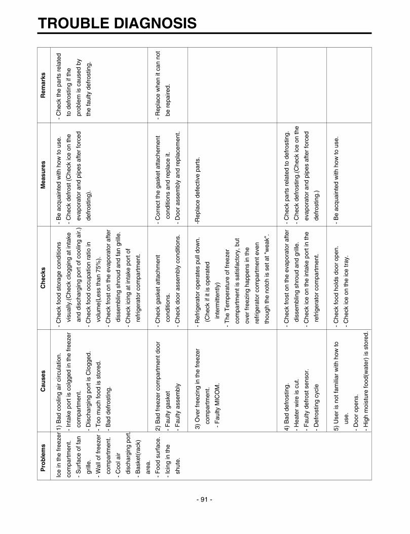
TROUBLE DIAGNOSIS
- 91 -
Pro
ble
ms
Cau
ses
Ch
ecks
Mea
sure
sR
emar
ks
Ice
in th
e fr
eeze
r 1)
Bad
coo
ling
air
circ
ulat
ion.
- C
heck
food
sto
rage
con
ditio
ns
- B
e ac
quai
nted
with
how
to u
se.
- C
heck
the
part
s re
late
d
com
part
men
t.-
Inta
ke p
ort i
s co
lgge
d in
the
free
zer
visu
ally
.(C
heck
clo
ggin
g at
inta
ke
- C
heck
def
rost
(C
heck
ice
on th
eto
def
rost
ing
if th
e
- S
urfa
ce o
f fan
com
part
men
t.an
d di
scha
rgin
g po
rt o
f coo
ling
air.
)ev
apor
ator
and
pip
es a
fter
forc
edpr
oble
m is
cau
sed
by
grill
e.-
Dis
char
ging
por
t is
Clo
gged
.-
Che
ck fo
od o
ccup
atio
n ra
tio in
de
fros
ting)
.th
e fa
ulty
def
rost
ing.
- W
all o
f fre
ezer
- T
oo m
uch
food
is s
tore
d.vo
lum
e(Le
ss th
an 7
5%).
com
part
men
t.-
Bad
def
rost
ing.
- C
heck
fros
t on
the
evap
orat
or a
fter
- C
ool a
irdi
ssem
blin
g sh
roud
and
fan
grill
e.
disc
harg
ing
port
.-
Che
ck ic
ing
at in
take
por
t of
- B
aske
t(ra
ck)
refr
iger
ator
com
part
men
t.
area
.
- F
ood
surf
ace.
2) B
ad fr
eeze
r co
mpa
rtm
ent d
oor
- C
heck
gas
ket a
ttach
men
t -
Cor
rect
the
gask
et a
ttach
emen
t-
Rep
lace
whe
n it
can
not
- Ic
ing
in th
e-
Fau
lty g
aske
tco
nditi
ons.
cond
ition
s an
d re
plac
e it.
be r
epai
red.
shut
e.-
Fau
lty a
ssem
bly
- C
heck
doo
r as
sem
bly
cond
ition
s.-
Doo
r as
sem
bly
and
repl
acem
ent.
3) O
ver
free
zing
in th
e fr
eeze
r -
Ref
riger
ator
ope
rate
s pu
ll do
wn.
-Rep
lace
def
ectiv
e pa
rts.
com
part
men
t.(C
heck
if it
is o
pera
ted
- F
aulty
MIC
OM
.in
term
itten
tly)
- T
he T
empe
ratu
re o
f fre
ezer
com
part
men
t is
satis
fact
ory,
but
over
free
zing
hap
pens
in th
e
refr
iger
ator
com
part
men
t eve
n
thou
gh th
e no
tch
is s
et a
t "w
eak"
.
4) B
ad d
efro
stin
g.-
Che
ck fr
ost o
n th
e ev
apor
ator
afte
r-
Che
ck p
arts
rel
ated
to d
efro
stin
g.
- H
eate
r w
ire is
cut
.di
ssem
blin
g sh
roud
and
gril
le.
- C
heck
def
rost
ing.
(Che
ck ic
e on
the
- F
aulty
def
rost
sen
sor.
- C
heck
ice
on th
e in
take
por
t in
the
evap
orat
or a
nd p
ipes
afte
r fo
rced
- D
efro
stin
g cy
cle
refr
iger
ator
com
part
men
t.de
fros
ting.
)
5) U
ser
is n
ot fa
mili
ar w
ith h
ow to
-
Che
ck fo
od h
olds
doo
r op
en.
- B
e ac
quai
nted
with
how
to u
se.
use.
- C
heck
ice
on th
e ic
e tr
ay.
- D
oor
open
s.
- H
igh
moi
stur
e fo
od(w
ater
) is
sto
red.

2-7.
So
un
d
TROUBLE DIAGNOSIS
- 92 -
Pro
ble
ms
Cau
ses
Ch
ecks
Mea
sure
sR
emar
ks
"Whi
zz"
soun
d1.
Lou
d so
und
of c
ompr
esso
r 1.
1 C
heck
the
leve
l of t
he
1) M
aint
ain
horiz
onta
l lev
el.
oper
atio
n.re
frig
erat
or.
2) R
epla
ce r
ubbe
r an
d se
at if
they
1.2
Che
ck th
e ru
bber
sea
t ar
e sa
gged
and
age
d.
cond
ition
s (s
aggi
ng a
nd a
ging
).3)
Inse
rt r
ubbe
r w
here
han
d co
ntac
t
redu
ces
nois
e in
the
pipe
.
2. P
ipes
res
onat
sou
nd w
hich
is
2.1
Che
ck th
e le
vel o
f pip
es4)
Avo
id p
ipe
inte
rfer
ence
.
conn
ecte
d to
the
com
pres
sor.
conn
ecte
d to
the
com
pres
sor
5) R
epla
ce d
efec
tive
fan
and
fan
and
thei
r in
terf
eren
ce.
mot
or.
2.2
Che
ck r
ubbe
r in
sert
ing
6) A
djus
t fan
to b
e in
the
cent
er o
f
cond
ition
s in
pip
es.
bell
mou
th o
f the
fan
guid
e.
2.3
Tou
ch p
ipes
with
han
ds o
r sc
rew
7) L
eve
a cl
eara
nce
betw
een
-driv
er (
chec
k th
e ch
ange
of
inte
rfer
ing
part
s an
d se
al g
aps
in
soun
d).
the
stru
ctur
es.
8) R
eass
embl
e th
e pa
rts
whi
ch m
ake
3. F
an o
pera
tion
soun
d in
the
free
zer
3.1
Che
ck fa
n in
sert
ion
dept
h an
d so
und.
com
part
men
t.bl
ade
dam
age.
9) L
eave
a c
lear
ance
if e
vapo
rato
r
3.2
Che
ck th
e in
terf
eren
ce w
ith
pipe
s an
d su
ctio
n pi
pe to
uch
stru
ctur
es.
free
zer
shro
ud.
3.3
Che
ck fa
n m
otor
.
3.4
Che
ck fa
n m
otor
rub
ber
inse
rtio
n
and
agin
g co
nditi
ons.
4. F
an o
pera
tion
soun
d in
the
4.1
Sam
e as
fan
conf
irmat
ion
in th
e
com
pres
sor
com
part
men
t.re
frig
erat
or.
4.2
Che
ck d
rip tr
ay le
g in
sert
ion.
4.3
Che
ck th
e sc
rew
fast
enin
g
cond
ition
s at
con
dens
er a
nd
drip
tray
.

TROUBLE DIAGNOSIS
- 93 -
Pro
ble
ms
Cau
ses
Ch
ecks
Mea
sure
sR
emar
ks
Vib
ratio
n so
und.
1. V
ibra
tion
of s
helv
es a
nd fo
ods
in1-
1. R
emov
e an
d re
plac
e th
e
1) R
eass
embl
e th
e vi
brat
ing
part
s
("C
luck
")th
e re
frig
erat
or.
shel
ves
in th
e re
frig
erat
oran
d in
sert
foam
or
cush
ion
whe
re
2. P
ipes
inte
rfer
ence
and
cap
illar
y1-
2. C
heck
ligh
t foo
d an
d co
ntai
ner
vibr
atio
n is
sev
ere.
tube
touc
hing
in th
e co
mpr
esso
r.on
the
shel
ves.
2) L
eave
a c
lear
ance
whe
re p
arts
com
part
men
t.2-
1. T
ouch
pip
es in
the
com
pres
sore
in
terf
ere
with
eac
h ot
her.
3. C
ompr
esso
r st
oppe
r vi
brat
ion.
com
part
men
t with
han
ds.
3) R
educ
e vi
brat
ion
with
rub
ber
4. M
ovin
g w
heel
vib
ratio
n.2-
2 C
heck
cap
illar
y tu
be to
uche
s an
d re
stra
iner
if it
is s
ever
e.
5. O
ther
str
uctu
re a
nd p
arts
co
ver
back
.(e
spec
ially
, com
pres
sor
and
pipe
).
vibr
atio
n.3-
1 C
heck
com
pres
sor
stop
per
4) R
epla
ce c
ompr
esso
r st
oppe
r if
it
vibr
atio
n.vi
btat
es s
ever
ely.
4-1
Che
ck v
ibra
tion
of fr
ont a
nd r
ear
mov
ing
whe
els.
5-1
Tou
ch o
ther
str
uctu
res
and
part
s.
Irre
gula
r so
und.
1. It
is c
ause
d by
hea
t exp
ansi
on1-
1 C
heck
tim
e an
d pl
ace
of s
ound
1)
Exp
lain
the
prin
cipl
es o
f ref
riger
atio
n
("C
lick"
).an
d co
ntra
ctio
n of
eva
pora
tor,
sour
ces.
and
that
the
tem
pera
ture
diff
eren
ce
shel
ves,
and
pip
es in
the
betw
een
oper
atio
n an
d de
fros
ting
refr
iger
ator
.ca
n m
ake
soun
ds.
2) If
eva
pora
tor p
ipe
cont
acts
with
oth
er
stru
ctur
es, l
eave
a c
lear
ance
bet
wee
n
them
(fre
ezer
shr
oud
or in
ner c
ase)
.

TROUBLE DIAGNOSIS
- 94 -
Pro
ble
ms
Cau
ses
Ch
ecks
Mea
sure
sR
emar
ks
Sou
nd "
Bur
ping
"It
happ
ens
whe
n re
frig
eran
t exp
ands
- C
heck
the
soun
d of
refri
gera
nt a
t the
- C
heck
the
rest
rain
er a
ttach
ed o
n th
e
(alm
ost t
he s
ame
at th
e en
d of
cap
illar
y tu
be.
initi
al in
stal
latio
n.ev
apor
ator
and
cap
illar
y tu
be w
eld
as a
nim
als
cryi
ng- C
heck
the
soun
d w
hen
the
refri
gera
tor
join
ts a
nd a
ttach
ano
ther
rest
rain
er.
soun
d).
star
ts o
pera
tion
afte
r for
ced
defro
stin
g.- I
f it i
s co
ntin
uous
and
ser
vere
, ins
ert
- Che
ck th
e re
stra
iner
atta
chm
ent
capi
llary
tube
aga
in (d
epth
:15±
3mm
)
cond
ition
s on
the
evap
orat
or a
nd- F
aste
n th
e ca
pilla
ry tu
be to
suc
tion
capi
llary
tube
wel
d jo
ints
.pi
pes
or d
etac
h in
the
com
pres
sor
com
partm
ent.
- Exp
lain
the
prin
cipl
es o
f fre
ezin
g
cycl
es.
Wat
er b
oilin
g or
It ha
ppen
s w
hen
refri
gera
nt p
asse
s- C
heck
the
soun
d w
hen
com
pres
sor i
s- E
xpla
in th
e pr
inci
ples
of f
reez
ing
cycl
es
flow
ing
soun
d.or
ifice
in a
ccum
ulat
or in
tern
al p
ipes
by
turn
ed o
n.an
d re
frige
rant
flow
ing
phen
omen
on b
y
the
pres
sure
diff
eren
ce b
etw
een
- Che
ck th
e so
und
whe
n co
mpr
esso
r is
inte
rnal
pre
ssur
e di
ffere
nce.
cond
ense
r and
eva
pora
tor.
turn
ed o
ff.- I
f sou
nd is
ser
vere
, wra
p th
e
accu
mul
ator
with
foam
and
rest
rain
er.
Sou
nd o
f whi
stle
Whe
n do
or c
lose
s, th
e in
tern
al p
ress
ure
- Che
ck th
e so
und
by o
peni
ng a
nd
- Bro
aden
the
cap
of d
isch
arge
hos
e fo
r
whe
n do
or
of th
e re
frige
rato
r dec
reas
es s
harp
lycl
osin
g th
e re
frige
rato
r or f
reez
er d
oors
.de
frost
ing
in th
e co
mpr
esso
r
clos
es.
belo
w a
tom
osph
ere
and
suck
s ai
r int
oco
mpa
rtmen
t.
the
refri
gera
tor,
mak
ing
the
whi
stle
- S
eal t
he g
ap w
ith s
eala
nt b
etw
een
out
soun
d.an
d in
ner c
ases
of h
inge
in d
oor.

2-8.
Od
or
TROUBLE DIAGNOSIS
- 95 -
Pro
ble
ms
Cau
ses
Ch
ecks
Mea
sure
sR
emar
ks
Foo
d O
dor.
Foo
d (g
arlic
, kim
chi,
etc)
- C
heck
the
food
is n
ot w
rapp
ed.
- D
ry d
eodo
rizer
in th
e sh
iny
and
- C
heck
the
shel
ves
or in
ner
win
dy p
lace
.
wal
l are
sta
ined
with
food
juic
e.-
Sto
re th
e fo
od in
the
clos
ed
- C
heck
the
food
in th
e vi
nyl w
raps
.co
ntai
ner
inst
ead
of v
inyl
wra
ps.
- C
hedk
food
cle
anlin
ess.
- C
lean
the
refr
iger
ator
and
set
butto
n at
"st
rong
".
Pla
stic
Odo
r.O
dors
of m
ixed
food
and
pla
stic
-
Che
ck w
et fo
od is
wra
pped
with
-
Cle
an th
e re
frig
erat
or.
odor
s.pl
astic
bow
l and
bag
.-
Per
suad
e cu
stom
ers
not t
o us
e
- It
happ
ens
in th
e ne
w r
efrig
erat
or.
plas
tic b
ag o
r w
raps
with
wet
food
or o
doro
us fo
ods.
Odo
r fr
om th
eO
dor
from
the
old
deod
oriz
er.
- C
heck
the
deod
oriz
er o
dors
.-
Dry
the
deod
oriz
er w
ith d
ryer
and
*D
eodo
rizer
: op
tion
deod
oriz
er.
then
in th
e sh
iny
and
win
dy p
lace
.
- R
emov
e an
d re
plac
e th
e
deod
oran
ts.
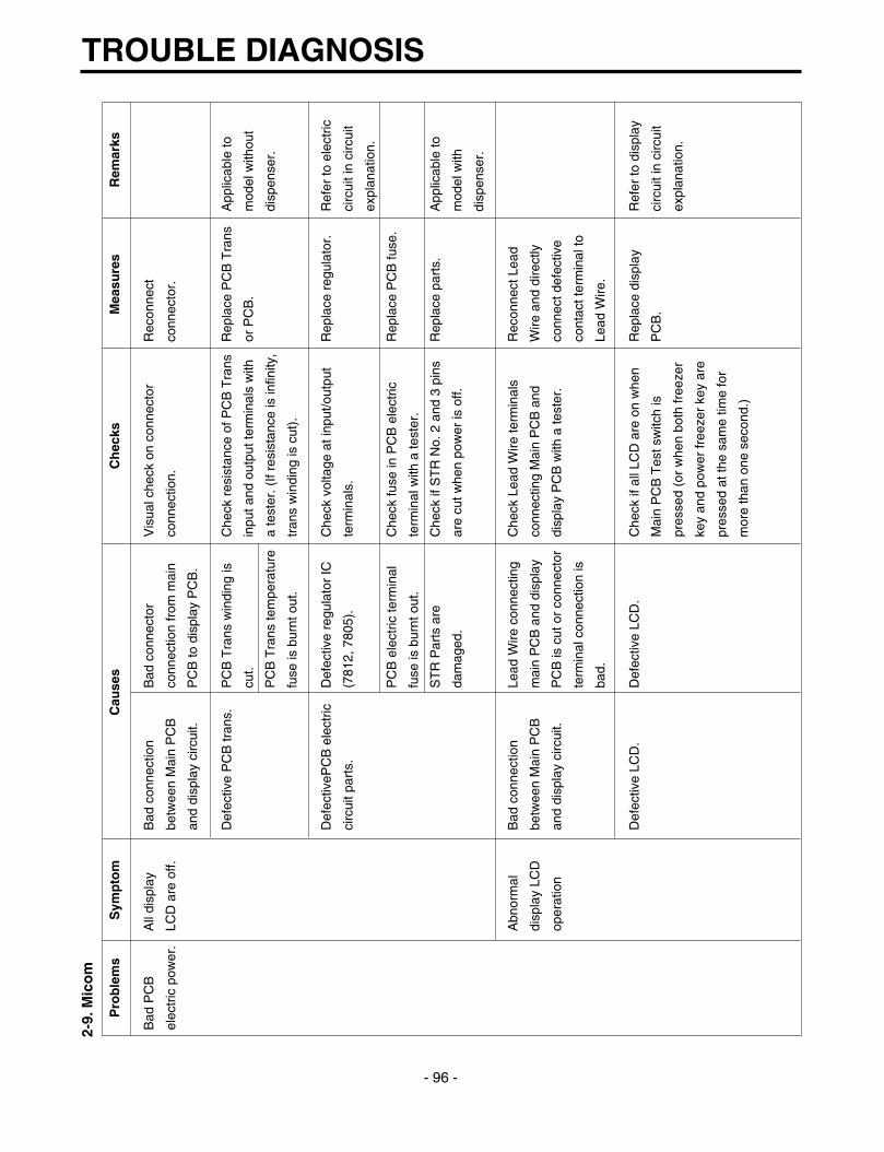
2-9.
Mic
om
TROUBLE DIAGNOSIS
- 96 -
Pro
ble
ms
Sym
pto
mC
ause
sC
hec
ksM
easu
res
Rem
arks
Bad
PC
B
All
disp
lay
Bad
con
nect
ion
Bad
con
nect
orV
isua
l che
ck o
n co
nnec
tor
Rec
onne
ct
elec
tric
pow
er.
LCD
are
off.
betw
een
Mai
n P
CB
co
nnec
tion
from
mai
n co
nnec
tion.
conn
ecto
r.
and
disp
lay
circ
uit.
PC
B to
dis
play
PC
B.
Def
ectiv
e P
CB
tran
s.P
CB
Tra
ns w
indi
ng is
C
heck
res
ista
nce
of P
CB
Tra
nsR
epla
ce P
CB
Tra
nsA
pplic
able
to
cut.
inpu
t and
out
put t
erm
inal
s w
ithor
PC
B.
mod
el w
ithou
t
PC
B T
rans
tem
pera
ture
a te
ster
. (If
resi
stan
ce is
infin
ity,
disp
ense
r.
fuse
is b
urnt
out
.tr
ans
win
ding
is c
ut).
Def
ectiv
ePC
B e
lect
ricD
efec
tive
regu
lato
r IC
Che
ck v
olta
ge a
t inp
ut/o
utpu
tR
epla
ce r
egul
ator
.R
efer
to e
lect
ric
circ
uit p
arts
.(7
812,
780
5).
term
inal
s.ci
rcui
t in
circ
uit
expl
anat
ion.
PC
B e
lect
ric te
rmin
alC
heck
fuse
in P
CB
ele
ctric
R
epla
ce P
CB
fuse
.
fuse
is b
urnt
out
.te
rmin
al w
ith a
test
er.
ST
R P
arts
are
C
heck
if S
TR
No.
2 a
nd 3
pin
sR
epla
ce p
arts
.A
pplic
able
to
dam
aged
.ar
e cu
t whe
n po
wer
is o
ff.m
odel
with
disp
ense
r.
Abn
orm
al
Bad
con
nect
ion
Lead
Wire
con
nect
ing
Che
ck L
ead
Wire
term
inal
s R
econ
nect
Lea
d
disp
lay
LCD
betw
een
Mai
n P
CB
m
ain
PC
B a
nd d
ispl
ayco
nnec
ting
Mai
n P
CB
and
W
ire a
nd d
irect
ly
oper
atio
nan
d di
spla
y ci
rcui
t.P
CB
is c
ut o
r co
nnec
tor
disp
lay
PC
B w
ith a
test
er.
conn
ect d
efec
tive
term
inal
con
nect
ion
isco
ntac
t ter
min
al to
bad.
Lead
Wire
.
Def
ectiv
e LC
D.
Def
ectiv
e LC
D.
Che
ck if
all
LCD
are
on
whe
n R
epla
ce d
ispl
ay
Ref
er to
dis
play
Mai
n P
CB
Tes
t sw
itch
is
PC
B.
circ
uit i
n ci
rcui
t
pres
sed
(or
whe
n bo
th fr
eeze
rex
plan
atio
n.
key
and
pow
er fr
eeze
r ke
y ar
e
pres
sed
at th
e sa
me
time
for
mor
e th
an o
ne s
econ
d.)

TROUBLE DIAGNOSIS
- 97 -
Pro
ble
ms
Sym
pto
mC
ause
sC
hec
ksM
easu
res
Rem
arks
Bad
coo
ling.
Fre
ezer
C
ompr
esso
r do
esC
ompr
esso
r Le
ad W
ireC
heck
com
pres
sor
Lead
Wire
R
econ
nect
Lea
d
tem
pera
ture
isno
t sta
rt.
is c
ut.
with
a te
ster
.W
ire.
high
.D
efec
tive
com
pres
sor
Mea
sure
vol
tage
at P
CB
CO
N2
Rep
lace
rel
ay(R
Y1
Ref
er to
load
driv
ing
rela
y.(3
&9)
afte
r pr
essi
ng m
ain
PC
Ban
d R
Y2)
or
PC
B.
driv
ing
circ
uit i
n
test
sw
itch
once
. It i
s O
K if
ci
rcui
t
volta
ge is
nor
mal
.ex
plan
atio
n.
Def
ectiv
e fr
eeze
r D
efec
tive
Fre
ezer
C
heck
res
ista
nce
of fr
eeze
r R
epla
ce fr
eeze
r R
efer
to
sens
or.
sens
or p
arts
.se
nsor
with
a te
ster
.se
nsor
.re
sist
ance
char
acte
ristic
s
tabl
e of
sen
sor
in
circ
uit
Fre
ezer
sen
sor
isC
onfir
m th
e co
lor
of s
enso
r in
R
epai
r m
ain
PC
Bex
plan
atio
n.
subs
titut
ed fo
r ot
her
circ
uits
(m
ain
PC
B s
enso
r se
nsor
hou
sing
sens
or.
hous
ing)
.
Def
ectiv
e fr
eeze
r fa
nF
an m
otor
lead
wire
C
heck
fan
mot
or le
ad w
ire
Rec
onne
ct le
ad
mot
or.
is c
ut.
with
a te
ster
.w
ire.
• D
efec
tive
door
sw
itch
Mea
sure
the
volta
ge b
etw
een
• R
epla
ce d
oor
Ref
er to
load
(fre
ezer
, ref
riger
ator
,P
CB
pow
er b
lue
line
and
fan
switc
h (f
reez
er,
driv
ing
circ
uits
in
hom
e ba
r).
mot
or a
fter
pres
sing
test
sw
itch
refr
iger
ator
and
ci
rcui
t
• D
efec
tive
fan
mot
or.
of M
ain
PC
B. I
f the
vol
tage
is
hom
e ba
r).
expl
anat
ion.
• D
efec
tive
fan
mot
orno
rmal
, it i
s O
K.
• R
epla
ce fa
n m
otor
.
driv
ing
rela
y.
Fau
lty d
efro
st.
Ref
er to
faul
ty d
efro
st it
ems
in tr
oubl
e di
agno
sis
Ref
er to
trou
ble
func
tions
.di
agno
sis
func
tion.

TROUBLE DIAGNOSIS
- 98 -
Pro
ble
ms
Sym
pto
mC
ause
sC
hec
ksM
easu
res
Rem
arks
Bad
coo
ling
Wro
ng
Def
ectiv
e S
tep
Mot
or
Che
ck S
tep
Mot
or
Che
ck if
Ste
p M
otor
dam
per
Rec
onne
ct le
ad
Ref
riger
ator
Dam
per.
dam
per
mot
or a
nd
mot
or a
nd r
eed
switc
h le
ad
wire
.
tem
pera
ture
.re
ed s
witc
h an
d le
ad
wire
are
cut
with
a te
ster
.
wire
are
cut
. Che
ck
Ref
er to
Ste
p M
otor
dam
per
Rep
lace
Ste
p M
otor
Ste
p M
otor
dam
per
in p
arts
rep
air
guid
e.da
mpe
ror r
efrig
erat
or
part
.co
ntro
l box
Ass
y.
Che
ck S
tep
Mot
or
Ref
er to
Ste
p M
otor
dam
per
Rep
lace
rel
ay o
r R
efer
to s
ingl
e
dam
per
Mot
or d
rivin
g in
par
ts r
epai
r gu
ide.
PC
B.
mot
or d
ampe
r
rela
y in
PC
B.
driv
ing
circ
uits
in c
ircui
t
expl
anat
ion.
For
eign
mat
eria
ls in
Ste
p C
heck
Ste
p M
otor
dam
per
Rem
ove
fore
ign
Mot
or d
ampe
r ba
ffles
.ba
ffle
visu
ally
.m
ater
ials
.
Ice
form
atio
n on
C
heck
if S
tep
Mot
or d
ampe
r R
epla
ce S
tep
Mot
or
Ste
p M
otor
dam
per
Hea
ter
wire
is c
ut w
ith a
da
mpe
r or
ref
riger
ator
baffl
es.
test
er.
cont
rol B
ox A
ssy.
Def
ectiv
e re
frig
erat
orD
efec
tive
refr
iger
ator
Che
ck th
e re
sist
ance
of
Rep
lace
ref
riger
ator
Ref
er to
sen
sor
sens
orse
nsor
par
ts.
refr
iger
ator
sen
sor
with
a te
ster
.se
nsor
.re
sist
ance
char
acte
ristic
tabl
e in
circ
uit
expl
anat
ion.
Ref
riger
ator
sen
sor
isC
heck
the
sens
or c
olor
in th
e R
epai
r m
ain
PC
B
subs
titut
ed fo
r ot
her
circ
uit.
(mai
n P
CB
sen
sor
sens
or h
ousi
ng.
sens
or.
hous
ing.
)
Def
ectiv
e re
frig
erat
orC
heck
if r
efrig
erat
or s
enso
rF
ix a
gain
the
sens
or a
ssem
bly
is n
ot fi
xed
at c
over
sen
sor
but
refr
iger
ator
sen
sor.
cond
ition
.in
ner
case
vis
ually
.

TROUBLE DIAGNOSIS
- 99 -
Pro
ble
ms
Sym
pto
mC
ause
sC
hec
ksM
easu
res
Rem
arks
Bad
def
rost
.D
efro
st is
not
Def
rost
lead
wire
is c
ut.
Che
ck if
def
rost
lead
wire
is c
ut w
ith a
R
econ
nect
Lea
d
wor
king
.te
ster
.W
ire.
Def
ectiv
e de
fros
t driv
ing
rela
y.C
heck
the
volta
ge o
f CO
N2
(1 a
nd 7
) R
epla
ce r
elay
(R
Y 7
Ref
er to
load
with
a te
ster
afte
r pr
essi
ng m
ain
and
RY
3)
or P
CB
.dr
ivin
g co
nditi
ons
PC
B te
st s
witc
h tw
ice.
ch
eck
in c
ircui
t
If th
e vo
ltage
is n
orm
al th
en it
is O
K.
expl
anat
ion.
Def
ectiv
e de
fros
t sen
sor
part
s.C
heck
the
resi
stan
ce o
f def
rost
sen
sor
Rep
lace
def
rost
R
efer
to s
enso
r
with
a te
ster
.se
nsor
.re
sist
ance
char
acte
ristic
tabl
e of
circ
uit
expl
anat
ion.
Def
ectiv
e B
uzze
r D
efec
tive
conn
ectin
g le
ad w
ire fr
om
Che
ck le
ad w
ire r
elat
ed to
doo
r R
epai
r le
ad w
ire.
buzz
erco
ntin
uous
lym
ain
PC
B to
doo
r sw
itch.
switc
h w
ith a
test
er.
rings
or
door
Def
ectiv
e do
or s
witc
h pa
rts.
Ref
er to
doo
r sw
itch
in p
arts
rep
air
Rep
lace
doo
r sw
itch.
open
ing
alar
m
guid
e.
does
not
wor
k.
Def
ectiv
e B
uzze
r do
es
Key
inpu
t wire
is c
ut o
r ba
d co
nnec
tor
Che
ck in
put w
ire w
ith a
test
er.
Rec
onne
ct le
ad
Ref
er to
dis
play
disp
lay
butto
nno
t rin
g an
d te
rmin
al c
onta
ct in
mai
n P
CB
and
w
ire a
nd r
epla
ce o
r ci
rcui
t in
circ
uit
key
does
not
disp
lay
PC
B c
onne
ctin
g le
ad w
ire.
dire
ctly
con
nect
bad
expl
anat
ion.
sens
e ev
en
cont
act t
erm
inal
to
butto
n is
le
ad w
ire.
pres
sed.
Key
is c
ontin
uous
ly d
epre
ssed
due
to
Dis
asse
mbl
e fr
ame
disp
lay
and
conf
irm
Adj
ust o
r re
plac
e
stru
ctur
al in
terf
eren
ce.
visu
ally
.in
terf
erin
g
stru
ctur
es.

TROUBLE DIAGNOSIS
- 100 -
Pro
ble
ms
Sym
pto
mC
ause
sC
hec
ksM
easu
res
Rem
arks
Def
ectiv
eB
uzze
r rin
gs
Tro
uble
mod
e in
dica
tion.
Che
ck tr
oubl
e di
agno
sis
func
tion.
Rep
air
trou
bles
Ref
er to
mod
e
disp
lay
butto
n.bu
t key
doe
sin
dica
tion
in
not s
ense
eve
nfu
nctio
n
butto
n is
ex
plan
atio
ns.
pres
sed.
Doo
r B
uzze
rB
uzze
r D
efec
tive
conn
ectin
g le
ad w
ire fr
om
Che
ck le
ad w
ire a
ssoc
iate
d w
ith d
oor
Rep
air
lead
wire
.C
heck
mod
el
cont
inuo
usly
mai
n P
CB
to d
oor
switc
h.sw
itch.
with
dis
pens
er.
rings
or
door
Def
ectiv
e fr
eeze
r co
mpa
rtm
ent d
oor
Ref
er to
doo
r sw
itch
in p
arts
rep
air
Rep
lace
Fre
ezer
open
ing
alar
msw
itch
part
s.gu
ide.
com
part
men
t doo
r
does
not
wor
k.sw
itch.
Bad
wat
er/ic
eIc
e an
d w
ater
Def
ectiv
e co
nnec
ting
lead
wire
from
C
heck
Lea
d W
ire a
ssoc
iate
d w
ith le
ver
Rep
air
lead
wire
.
disp
ense
r.ar
e no
tM
ain
PC
B to
leve
r sw
itch.
switc
h w
ith a
test
er.
disp
ense
d.D
efec
tive
leve
r sw
itch
part
sR
efer
to d
oor
switc
h in
par
ts r
epai
r gu
ide.
Rep
lace
leve
r sw
itch.
Def
ectiv
e ph
oto
coup
ler
IC p
arts
.C
heck
vol
tage
cha
nge
at p
hoto
cou
pler
Rep
lace
pho
to
outp
ut te
rmin
als
with
leve
r sw
itch
coup
ler
IC o
r P
CB
.
pres
sed.
It is
OK
if v
olta
ge c
hang
e is
betw
een
0V
- 5
V.
Def
ectiv
e re
lay
asso
ciat
ed w
ith ic
e C
heck
rel
ay (
RY
4, R
Y5,
RY
12)
Rep
lace
def
ectiv
e
disp
ense
(ge
ared
mot
or, c
ube
and
with
a te
ster
.re
lay.
disp
ense
r so
leno
id).
Def
ectiv
e pa
rts
asso
ciat
ed w
ith ic
e C
heck
res
ista
nce
of p
arts
with
a te
ster
.R
epla
ce d
efec
tive
disp
ense
(ge
ared
mot
or, c
ube
and
part
s.
disp
ense
r so
leno
id).
Def
ectiv
e re
lay
asso
ciat
ed w
ith w
ater
Che
ck r
elay
(R
Y7)
with
a te
ster
Rep
lace
def
ectiv
e
disp
ense
.re
lay.
Def
ectiv
e pa
rts
asso
ciat
ed w
ith w
ater
Che
ck r
esis
tanc
e of
par
ts w
ith a
test
er.
Rep
lace
def
ectiv
e
disp
ense
r.pa
rts.
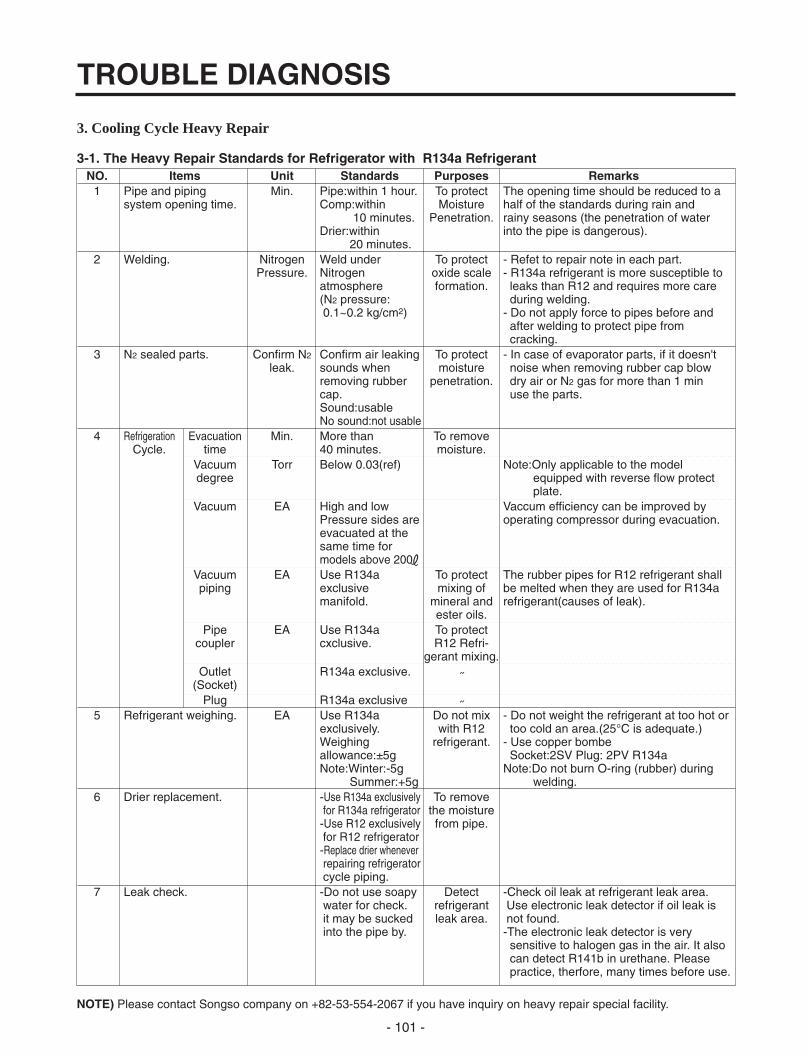
3. Cooling Cycle Heavy Repair
3-1. The Heavy Repair Standards for Refrigerator with R134a Refrigerant
NOTE) Please contact Songso company on +82-53-554-2067 if you have inquiry on heavy repair special facility.
TROUBLE DIAGNOSIS
- 101 -
NO. Items Unit Standards Purposes Remarks1 Pipe and piping Min. Pipe:within 1 hour. To protect The opening time should be reduced to a
system opening time. Comp:within Moisture half of the standards during rain and 10 minutes. Penetration. rainy seasons (the penetration of water
Drier:within into the pipe is dangerous).20 minutes.
2 Welding. Nitrogen Weld under To protect - Refet to repair note in each part.Pressure. Nitrogen oxide scale - R134a refrigerant is more susceptible to
atmosphere formation. leaks than R12 and requires more care(N2 pressure: during welding.0.1~0.2 kg/cm2) - Do not apply force to pipes before and
after welding to protect pipe from cracking.
3 N2 sealed parts. Confirm N2 Confirm air leaking To protect - In case of evaporator parts, if it doesn't leak. sounds when moisture noise when removing rubber cap blow
removing rubber penetration. dry air or N2 gas for more than 1 min cap. use the parts.Sound:usableNo sound:not usable
4 Refrigeration Evacuation Min. More than To removeCycle. time 40 minutes. moisture.
Vacuum Torr Below 0.03(ref) Note:Only applicable to the model degree equipped with reverse flow protect
plate.Vacuum EA High and low Vaccum efficiency can be improved by
Pressure sides are operating compressor during evacuation.evacuated at thesame time formodels above 200L
Vacuum EA Use R134a To protect The rubber pipes for R12 refrigerant shall piping exclusive mixing of be melted when they are used for R134a
manifold. mineral and refrigerant(causes of leak).ester oils.
Pipe EA Use R134a To protectcoupler cxclusive. R12 Refri-
gerant mixing.Outlet R134a exclusive. ˝
(Socket)Plug R134a exclusive ˝
5 Refrigerant weighing. EA Use R134a Do not mix - Do not weight the refrigerant at too hot or exclusively. with R12 too cold an area.(25°C is adequate.)Weighing refrigerant. - Use copper bombe allowance:±5g Socket:2SV Plug: 2PV R134aNote:Winter:-5g Note:Do not burn O-ring (rubber) during
Summer:+5g welding.6 Drier replacement. -Use R134a exclusively To remove
for R134a refrigerator the moisture-Use R12 exclusively from pipe.for R12 refrigerator-Replace drier wheneverrepairing refrigeratorcycle piping.
7 Leak check. -Do not use soapy Detect -Check oil leak at refrigerant leak area. water for check. refrigerant Use electronic leak detector if oil leak is it may be sucked leak area. not found.into the pipe by. -The electronic leak detector is very
sensitive to halogen gas in the air. It also can detect R141b in urethane. Please practice, therfore, many times before use.

3-2. Summary Of Heavy Repair
TROUBLE DIAGNOSIS
- 102 -
Process Contents Tools
- Cut charging pipe ends and discharge refrigerant from Filter, side cutters
drier and compressor.
- Use R134a oil and refrigerant for compressor and drier Pipe Cutter, Gas welder, N2 gas
- Confirm N2 sealing and packing conditions before use.
Use good one for welding and assembly.
- Weld under nitrogen gas atmosphere.(N2 gas pressure:
0.1-0.2kg/cm2).
- Repair in a clean and dry place.
- Evacuate for more than forty minutes after connecting Vacuum pump(R134a
manifold gauge hose and vacuum pump to high (drier) exclusively), Manifold gauge.
and low (compressor refrigerant discharging parts)
pressure sides.
- Evacuation Speed:113l/min.
- Weigh and control the allowance of R134a bombe in a R134a exclusive bombe(mass
vacuum conditions to be ±5 g with electronic scales and cylinder), refrigerant(R134a)
charge through compressor inlet manifold gauge, electronic
(Charge while refrigerator operates). scales, punching off flier,
- Weld carefully after inlet pinching. gas welding machine
- Check leak at weld joints. Electronic Leak Detector,
Minute leak: Use electronic leak detector Driver(Ruler).
Big leak: Check visually or fingers.
Note:Do not use soapy water for check.
- Check cooling capacity
➀ Check radiator manually to see if warm.
➁ Check hot line pipe manually to see if warm.
➂ Check frost formation on the whole surface of the
evaporator.
- Remove flux from the silver weld joints with soft brush Copper brush, Rag, Tool box
or wet rag.(Flux may be the cause of corrosion and
leaks.)
- Clean R134a exclusive tools and store them in a clean
tool box or in their place.
- Installation should be conducted in accordance with the
standard installation procedure.(Leave space of more
than 5 cm from the wall for compressor compartment
cooling fan mounted model.)
Troublediagnosis
Remove refrigerantResiduals
Partsreplacementand welding
Compressorcompartment
and toolsarrangement
Transportationand
installation
Checkrefrigerant leak
and coolingcapacity
Vacuum
Refrigerantcharging and
charginginlet welding

3-3. Precautions During Heavy Repair
TROUBLE DIAGNOSIS
- 103 -
Items Precautions
1. Use of tools. 1) Use special parts and tools for R134a.
2. Removal of retained 1) Remove retained refrigerant more than 5 minutes after turning off a refrigerator.
refrigerant. (If not, oil will leak inside.)
2) Remove retained refrigerant by cutting first high pressure side (drier part) with a nipper and
then cut low pressure side. (If the order is not observed, oil leak will happen.)
3. Replacement of drier. 1) Be sure to replace drier with R134a only when repairing pipes and injecting refrigerant.
4. Nitrogen blowing 1) Weld under nitrogen atmosphere in order to prevent oxidation inside a pipe.
welding. (Nitrogen pressure : 0.1~0.2 kg/cm2.)
5. Others. 1) Nitrogen or refrigerant R134a only should be used when cleaning inside of cycle pipes
inside and sealing.
2) Check leakage with an electronic leakage tester.
3) Be sure to use a pipe cutter when cutting pipes.
4) Be careful not the water let intrude into the inside of the cycle.
1
2
Compressor
Low pressure side CondenserHigh pressure side
Drier
Evaporator

3-4. Practical Work For Heavy Repair
TROUBLE DIAGNOSIS
- 104 -
Items Precautions
1. Removal of residual
refrigerant.
1) Remove residual refrigerant more than 5 minutes later after turning off the refrigerator.
( If not, compressor oil may leak inside.)
2) Remove retained refrigerant slowly by cutting first high pressure side (drier part) with a
nipper and then cut low pressure side.
2. Nitrogen blowing
welding.
When replacing a drier:
Weld and parts by blowing nitrogen(0.1~0.2kg/cm2) to high pressure side after
assembling a drier.
When replacing a compressor:
Weld and parts by blowing nitrogen to the low pressure side.
Note) For other parts, nitrogen blowing is not necessary because it does not produce oxidized
scales inside pipe because of its short welding time.
3. Replacement of drier.
Inserting a capillary tube
Measure distance with a ruler and put a mark(12+3/-0)on the capillary tube. Insert tube to the
mark, and weld it
KEYPOINTINGObserve the sequence forremoval of refrigerant.(If not, compressor oil mayleak.)
KEYPOINTINGWelding without nitrogenblowing produces oxidizedscales inside a pipe, whichaffect on performance andreliability of a product.
KEYPOINTINGBe sure to check theinserted length of capillarytube when it is inserted. (Iftoo much inserted, acapillary tube is clogged bya filter.)
Compressor
Low pressure side
CondenserHigh pressure side
Drier
Evaporator
ReleaseRefrigentIntake
Suction
1 2 1
2
Evaporator
Drier
High pressure sideCondenserRefrigent
Intake
12+3-0
Filter
* Unit : mm

TROUBLE DIAGNOSIS
- 105 -
Items Precautions
4.Vacuum degassing.
Pipe Connection
Connect a red hose to the high pressure side and a blue hose to the
low pressure side.
Vacuum Sequence
Open , valves and evacuate for 40 minutes. Close valve .
5.Refrigerant charging.
Charging sequence
1) Check the amount of refrigerant supplied to each model after completing vacuum
degassing.
2) Evacuate bombe with a vacuum pump.
3) Measure the amount of refrigerant charged.
- Measure the weight of an evacuated bombe with an electronic scale.
- Charge refrigerant into a bombe and measure the weight. Calculate the weight of
refrigerant charged into the bombe by subtracting the weight of an evacuated bombe.
KEYPOINTING- If power is applied
during vacuumdegassing, vacuumdegassing shall bemore effective.
- Operate compressorwhile chargingrefrigerant. (It iseasier and morecertain to do likethis.)
KEYPOINTING- Be sure to charge
the refrigerant ataround 25°C.
- Be sure to keep -5gin the winer and+5g in summer
the amount of refrigerant charged= a weight after charging -a weight before charging (a weight of an evacuated cylinder)
Calculation of amount of refrigerant charged
2 1
3
Compressor
Lowpressure
Condenser
Highpressure
Drier
Evaporator
RedYellow
Blue
VaccumPump
Suction pipe
R134a
Indicate the weight ofan evacuated bombe
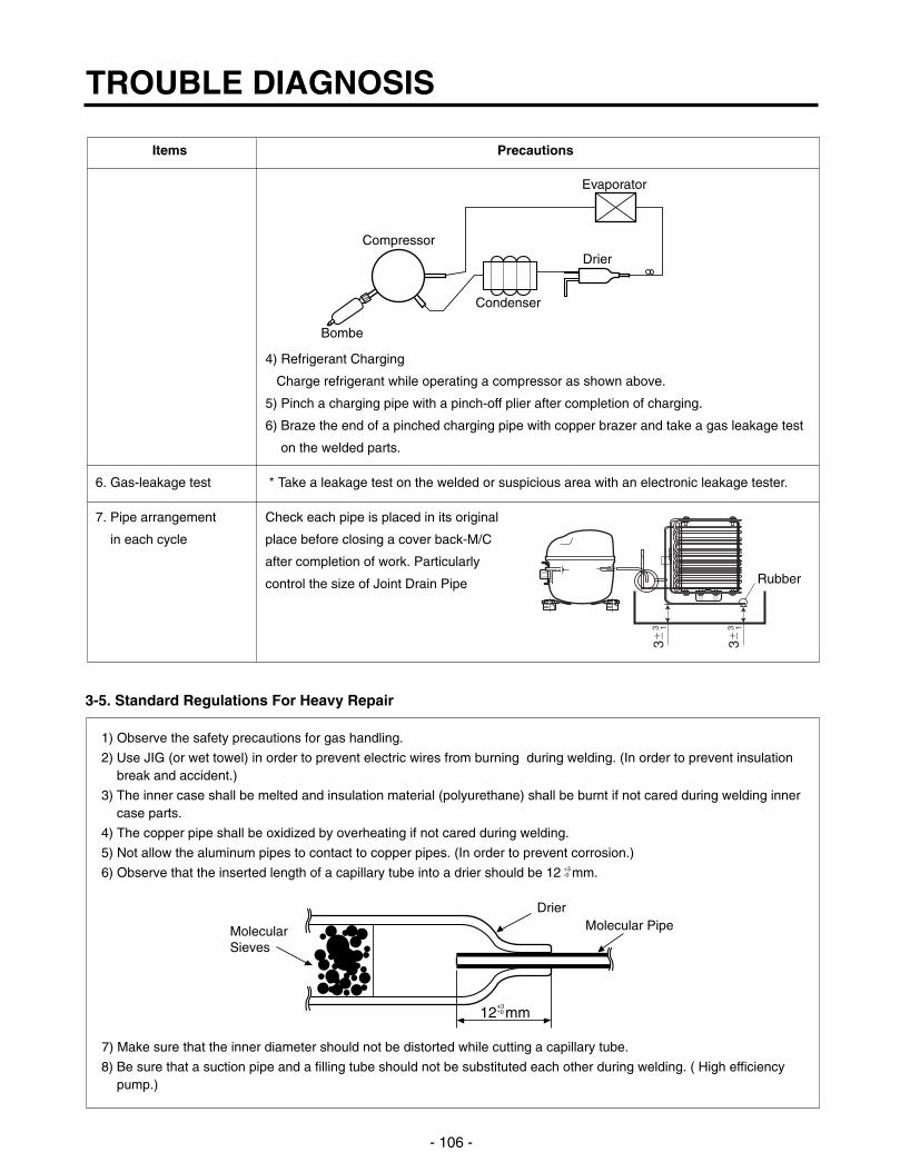
3-5. Standard Regulations For Heavy Repair
TROUBLE DIAGNOSIS
- 106 -
Items Precautions
4) Refrigerant Charging
Charge refrigerant while operating a compressor as shown above.
5) Pinch a charging pipe with a pinch-off plier after completion of charging.
6) Braze the end of a pinched charging pipe with copper brazer and take a gas leakage test
on the welded parts.
6. Gas-leakage test * Take a leakage test on the welded or suspicious area with an electronic leakage tester.
7. Pipe arrangement Check each pipe is placed in its original
in each cycle place before closing a cover back-M/C
after completion of work. Particularly
control the size of Joint Drain Pipe
Compressor
Condenser
Drier
Evaporator
Bombe
Rubber
1) Observe the safety precautions for gas handling.
2) Use JIG (or wet towel) in order to prevent electric wires from burning during welding. (In order to prevent insulationbreak and accident.)
3) The inner case shall be melted and insulation material (polyurethane) shall be burnt if not cared during welding innercase parts.
4) The copper pipe shall be oxidized by overheating if not cared during welding.
5) Not allow the aluminum pipes to contact to copper pipes. (In order to prevent corrosion.)
6) Observe that the inserted length of a capillary tube into a drier should be 12 mm.
7) Make sure that the inner diameter should not be distorted while cutting a capillary tube.
8) Be sure that a suction pipe and a filling tube should not be substituted each other during welding. ( High efficiencypump.)
12 mm+3-0
DrierMolecular PipeMolecular
Sieves
+3-0

3-6. Brazing Reference Drawings
TROUBLE DIAGNOSIS
- 107 -
PIPE ASSY, JOINT
PIPE ASSY, HOT LINE(Freezer)
PIPE ASSY, HOT LINE(Refrigerator)
PIPE ASSY, JOINT CONDENSER ASSY, WIRE
PIPE ASSY, SUCTION
DRIER ASSYCAPI - TUBE
Copper BrazerCopperBrazer
Silver Brazer
CopperBrazer
Copper BrazerCopper Brazer Coppper Brazer
Silver Brazer
CopperBrazer
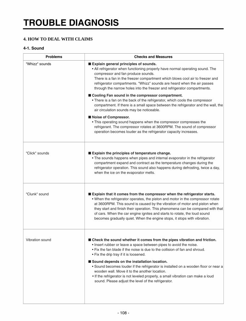
4. HOW TO DEAL WITH CLAIMS
4-1. Sound
TROUBLE DIAGNOSIS
- 108 -
Problems Checks and Measures
"Whizz" sounds Explain general principles of sounds.• All refrigerator when functioning properly have normal operating sound. The
compressor and fan produce sounds.There is a fan in the freezer compartment which blows cool air to freezer andrefrigerator compartments. "Whizz" sounds are heard when the air passesthrough the narrow holes into the freezer and refrigerator compartments.
Cooling Fan sound in the compressor compartment.• There is a fan on the back of the refrigerator, which cools the compressor
compartment. If there is a small space between the refrigerator and the wall, theair circulation sounds may be noticeable.
Noise of Compressor.• This operating sound happens when the compressor compresses the
refrigerant. The compressor rotates at 3600RPM. The sound of compressoroperation becomes louder as the refrigerator capacity increases.
"Click" sounds Explain the principles of temperature change.• The sounds happens when pipes and internal evaporator in the refrigerator
compartment expand and contract as the temperature changes during therefrigerator operation. This sound also happens during defrosting, twice a day,when the ice on the evaporator melts.
"Clunk" sound Explain that it comes from the compressor when the refrigerator starts.• When the refrigerator operates, the piston and motor in the compressor rotate
at 3600RPM. This sound is caused by the vibration of motor and piston whenthey start and finish their operation. This phenomena can be compared with thatof cars. When the car engine ignites and starts to rotate, the loud soundbecomes gradually quiet. When the engine stops, it stops with vibration.
Vibration sound Check the sound whether it comes from the pipes vibration and friction.• Insert rubber or leave a space between pipes to avoid the noise.• Fix the fan blade if the noise is due to the collision of fan and shroud.• Fix the drip tray if it is loosened.
Sound depends on the installation location.• Sound becomes louder if the refrigerator is installed on a wooden floor or near a
wooden wall. Move it to the another location.• If the refrigerator is not leveled properly, a small vibration can make a loud
sound. Please adjust the level of the refrigerator.

TROUBLE DIAGNOSIS
- 109 -
Problems Checks and Measures
Sounds of water flowing Explain the flow of refrigerant.• When the refrigerator stops, the water flowing sound happens.
This sound happens when the liquid or vapor refrigerant flows from theevaporator to compressor.
"Click" sounds Explain the characteriistics of moving parts.• This noise comes from the MICOM controller's switch on the top of the
refrigerator when it is turned on and off.
Noise of ice maker operation Explain the procedure and principles of ice maker operation.(applicable to model with ice maker). • Automatic ice maker repeats the cycle of water supplying icemaking ice - Noise produced by ice dropping ejection. When water is supplied, the water supply valve in the machine room and hitting ice bank. makes sounds like “Whizz” and water flowing also makes sound. When water
- Noise from motor sounds “Whizz”. freezes to ice, freezing sounds such as “click, click” are heard. When ice isbeing ejected, sounds like “Whizz” produced by a motor to rotate an ice trayand ice dropping and hitting ice bank sounds are also heard.
Noise when supplying water. Explain the principles of water supplied to dispenser.• When the water supply button in the dispenser is pressed, the water supply
valve in the compressor compartment opens and let the water flow to the watertank in the lower part of the refrigerator compartment. The water is dispensedby this pressure. When this happens, motor sound and water flowing sound areheard.
Noise when supplying ice. Explain the principles of ice supply and procedure of crushed ice making in adispenser.• When ice cube button is pressed, ice stored in the ice bank is moved by a Helix
Pusher and dispensed. If crushed ice button is pressed, the cube ice iscrushed. When this happens, ice crushing and hitting ice bank sounds areheard.
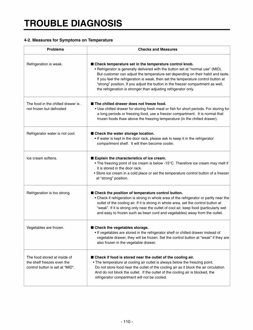
4-2. Measures for Symptoms on Temperature
TROUBLE DIAGNOSIS
- 110 -
Problems Checks and Measures
Refrigeration is weak. Check temperature set in the temperature control knob.• Refrigerator is generally delivered with the button set at “normal use” (MID).
But customer can adjust the temperature set depending on their habit and taste.If you feel the refrigeration is weak, then set the temperature control button at“strong” position. If you adjust the button in the freezer compartment as well, the refrigeration is stronger than adjusting refrigerator only.
The food in the chilled drawer is . The chilled drawer does not freeze food.not frozen but defrosted • Use chilled drawer for storing fresh meat or fish for short periods. For storing for
a long periods or freezing food, use a freezer compartment. It is normal thatfrozen foods thaw above the freezing temperature (in the chilled drawer).
Refrigerator water is not cool. Check the water storage location.• If water is kept in the door rack, please ask to keep it in the refrigerator
compartment shelf. It will then become cooler.
Ice cream softens. Explain the characteristics of ice cream.• The freezing point of ice cream is below -15°C. Therefore ice cream may melt if
it is stored in the door rack.• Store ice cream in a cold place or set the temperature control button of a freezer
at “strong” position.
Refrigeration is too strong. Check the position of temperature control button.• Check if refrigeration is strong in whole area of the refrigerator or partly near the
outlet of the cooling air. If it is strong in whole area, set the control button at“weak”. If it is strong only near the outlet of cool air, keep food (particularly wetand easy to frozen such as bean curd and vegetables) away from the outlet.
Vegetables are frozen. Check the vegetables storage.• If vegetables are stored in the refrigerator shelf or chilled drawer instead of
vegetable drawer, they will be frozen. Set the control button at “weak” if they arealso frozen in the vegetable drawer.
The food stored at inside of Check if food is stored near the outlet of the cooling air. the shelf freezes even the • The temperature at cooling air outlet is always below the freezing point. control button is set at “MID”. Do not store food near the outlet of the cooling air as it block the air circulation.
And do not block the outlet. If the outlet of the cooling air is blocked, therefrigerator compartment will not be cooled.

4-3. Odor and Frost
TROUBLE DIAGNOSIS
- 111 -
Problems Checks and Measures
Odor in the refrigerator compartment. Explain the basic principles of food odor.• Each food has its own peculiar odor. Therefore it is impossible to prevent or
avoid food odor completely when food is stored in the completely sealedrefrigerator compartment. Deodorizer can absorb some portions of the odor butnot completely. The intensity of odor depends on refrigerator conditions andenvironments.
Check the temperature control button and set at “strong”.• Clean inside of the refrigerator with detergent and remove moisture. Dry inside
the refrigerator by opening the door for about 3 or 4 hours and then set thetemperature control button at “strong”.
Frost in the freezer compartment Explain the basic principles of frost formation.• The main causes for frosting:
- Door was left open.- Air penetration through the gasket- Too frequent door opening. (parties. etc.)- Hot foods are stored before they are cooled down. The temperature of freezer
is -19°C. if temperature is set at “MID”. If hot air comes into the refrigerator,fine frost forms as cold air mixes with hot air. If this happens quite often, muchfrost forms inside of the refrigerator. If the door is left open in Summer, ice mayform inside of the refrigerator.
Frost in ice tray. Explain basic principles of frost formation.• When ice tray with full of water is put into a freezer compartment, the water
evaporates. If cool air fan operates, the moisture attached to the jaw (protrudedpart) of ice mold shall freeze and form frost. If warm water was put into the icemold, the situation will become worse.

4-5. Others
TROUBLE DIAGNOSIS
- 112 -
Problems Checks and Measures
The refrigerator case is hot. Explain the principles of radiator.• The radiator pipes are installed in the refrigerator case and partition plate
between the refrigerator and the freezer compartment in order to preventcondensation formation. Particularly in summer or after installation ofrefrigerator, it may feel hot but it is normal. If there is no enough space todissipate heat, it can be hotter due to lack of heat radiation. Please install arefrigerator in a well-ventilated place and leave a clearance between refrigeratorand wall:
Small holes in a door liner Explain that the hole is for releasing gas.• A small hole in the door liner is for releasing gas during insulation materials
lining work. With a releasing hole, forming can be easily done .
Electric bills are too much. Check the use conditions.• Too frequent door opening and hot food storing cause the compressor to
operate continuously and hence increase the electric consumption and bills.
Condensation on the inside Explain how to store foodswall of the refrigerator • Condensation forms when refrigerator is installed at damp area, door is compartment and the cover of frequently opened, and wet foods are not stored in the air tight container orproperly vegetable drawer. wrapped. Be sure to store wet foods in the air tight container or in the wrap.
When is the power connected? When should the power be connected ?• You can connect the power right after the installation. But if the refrigerator was
laid flat during transportation for a long period of time and the refrigerant andcompressor oils are mixed up, then this will affect badly the performance of arefrigerator. Be sure to connect the power 2~3 hours after refrigerator isinstalled.
Door does not open properly. Refrigerator compartment door does not open properly.• When the door is open, warm open air comes into the compartment and is mixed up with cool air. This mixed air shall be compressed and increase theinternal pressure when door is closed. This causes the door sticked closely tothe refrigerator in a moment. (If the refrigerator is used for a long time, it willthen open smoothly.)
When the refrigerator compartment door is open and close, the freezercompartment door moves up and down.• When the refrigerator compartment door is open and close, fresh air comes into
the freezer compartment and moves up and down the freezer compartmentdoor.
Door opens too easily.• There is a magnet in the gasket rubber so that it is ok. if door is securely closed
without a gap. It can be open easily if the foods in the refrigerator or freezercompartments hold the door open.
A door does not close properly. • If the rear side of the refrigerator is raised higher than front side, door shall not
be easily closed. Adjust the level of refrigerator with levelling screws.
The front side shouldbe raised a little bit higher
than the rear side.

1. DOOR
1) Remove lower cover and then disconnect watersupply tube in the lower part of freezer door.
• Pull a water supply tube forward while pressing partto disconnect water supply tube as shown below.
2) Remove a freezer door.(1) Loosen hinge cover screw of freezer door and remove
cover. Disconnect all connecting lines except earthing cord.
(2) Turn hinge lever in arrow A direction until it isloosened and take it out in arrow B direction.
Note : • When disconnecting refrigerator door, turn hingelever counterclockwise.
• If hinge lever or bracket hinge pin is deformedduring assembling freezer and refrigerator doors,fix two screws (Tap Tite Screw, M6: Hinge, L fixingscrew) in the hole of upper hinge.
(3) Disconnect upper hinge from a hinge supporter by grasping the front part of upper hinge and lifting up(Hinge Assy, U) in arrow direction A and pull forwardin arrow B direction. Be careful as the door may befallen down.
(4) Lift up the freezer door in arrow direction anddisconnect the door from the lower hinge . Don’t pulla door forward.
Note : • Lift up a freezer door until a water supply tube isfully taken out.
(5) Assembly is the reverse order of disassembly
HOW TO DISASSEMBLE AND ASSEMBLE
- 113 -
2
1 A A B
1
2
1
2
Cover, Hinge
2Connecting
Line
EarthingCord
Lever, Hinge
A
B

2. HANDLE 1) Put blade screwdriver into a groove on the side of a
Deco handle and lift up a little bit in arrow directionand push up with hand in arrow direction anddisconnect.
2) Put blade screwdriver into a groove on the side of aDECO handle and lift up in arrow direction and pushdown with hand in arrow direction and disconnect.
3) Push up a piece handle in arrow direction with handand disconnect.
4) Turn screw in arrow direction with a cross driver anddisconnect.
3. SHROUD, GRILLE FAN1) Loosen two screws after disconnecting a cap screw of a
grille fan(U) with a balde screwdriver.
2) Disassembly of a grille fan(U) : Pull forward afteropening hook at part with a blade screwdriver.
3) Disconnect housing A of a grille fan (L) from the mainbody.
4) Disassembly of a grille fan (L) : Hold upper part of agrille fan(L) and pull forward carefully.
5) Loosen two screws.
6) Disassembly of shroud. F(U) : Disconnect housing of Bafter removing two rail guides with a blade screwdriver.
7) Disassembly of shroud. F(U) : Hold upper part and pullforward.
8) Check foam PU sticking conditions around a shroud,F(U) and F(L) during assembling. If damaged, torn orbadly sticked, assemble with a new one after sealingwell.
4. ICEMAKER ASSY
1. Dispenser Model1) How to disassemble:
(1) Remove ice bank from the freezer compartment.
(2) Loosen two screws on the upper part of icemakerbracket.
(3) Disconnect icemaker bracket so that it can slideforward.
(4) Disconnect icemaker housing and sensor housing.
(5) Disconnect icemaker horizontally by pressing brackethook part. ( Don’t disassemble further. The set valuemay be changed.)
2) How to assemble : The assembly is the reverse order ofthe above disassembly.
Note : When the ice tray is not horizontal after assembly,assembly must be wrong. Check and assembleagain.
HOW TO DISASSEMBLE AND ASSEMBLE
- 114 -
1
Handle, Deco
2
3
4
Handle, Piece
Screw
Bracket, Ice MakerHook
Ice Maker Unit
Lever
Tray, Ice
Sensor
Insulation
Cover, Sensor

5. DISPENSER1) Disconnect button assembly by pulling down until it
stops and then pulling forward.
2) Remove display frame Assy by making a gap between adisplay frame Assy. and funnel Assy. with a baldescrewdriver and pulling it forward. The cover dispenseris fixed with a hook.
3) Display Assy can be disconnected by pressing theupper part of a cover dispenser and pushing a displayAssy. after disconnecting display frame Assy. housing.
4) Loosen four screws with a phillips screwdriver and pull afunnel Assy to disconnect.
5) Duct cap Assy is disconnected if hold lever connectingscrew is loosened with a phillips screwdriver.
6) For assembling a duct cap Assy., insert one end of aspring into the right hole of dispenser lever, and insertthe other end into the right hole in upper part ofdispenser. And then assemble a holder lever after fixinga holder at a solenoid Assy working part.
HOW TO DISASSEMBLE AND ASSEMBLE
- 115 -
Button
Funnel Assy
FunnelAssy
HolderLever
Solenoid Assy
Cap Assy,Duct
Spring
Heater, Sheet
Lever,Dispenser
Solenoid Assy

7) Dispenser Related Parts
HOW TO DISASSEMBLE AND ASSEMBLE
- 116 -
1821
19
7
12
8
11
14
17 15
24
16
277A
9
10
23
21
22
4
2
1
1 FRAME ASSY, DISPLAY
2 COVER, DISPENSER
4 PWB(PCB) ASSY, DISPLAY
7 FUNNEL ASSY
8 SWITCH, MICRO
9 FRAME, FUNNEL
10 LEVER(SWITCH)
11 FUNNEL
12 RUBBER, FUNNEL
13 SWITCH, ROCKER
14 SOLENOID ASSY
15 SPRING
16 HOLDER, LEVER
17 CAP, DUCT
19 LEVER, DISPENSER
20 RUBBER, CAP
21 BUTTON ASSY
22 BUTTON
23 HOLDER, BUTTON
24 DECO, DRAIN
< 17 Cap Assy, Duct Detailed Drawings>

6. WATER TANK AND WATER LINEu The water tank at back and lower part of a refrigerator is
fixed by one screw and has a capacity containing 7glasses (180cc per glass) of cold water. It will take timeto make more cold water in the tank.
* The first portion of dispensed water is not cold eventhough the refrigerator is working. In this case,dispense ice first in the cup and then water to make acold water.
7. HOME BAR
7-1. Home Bar related parts
7-2. Home Bar parts disassembly and assembly1) Disconnect H/Bar Door Assy .
2) Loosen two screws attached on the refrigeratorcompartment door with a phillips screwdriver. Andloosen 4 screws and two screws . Pull H/Bar doorAssy . forward to disassemble.
3) Loosen two screws , fixed on H/Bar door Assy. andtwo screws with a cross driver to disassemble armAssy.
4) Assemble parts by performing the disassembly inreverse order.
Note : • Assemble carefully parts , , until they arefixed firmly when assembling them.
• Adjust exterior gap by adjusting parts , andwhen assembling.
HOW TO DISASSEMBLE AND ASSEMBLE
- 117 -
1
8
675
11
109
8
7
6
4
3
1110
9 2.0
5.0
1.8 1.8
1 DOOR ASSY, H/BAR 7 SCREW TAP TITE(ARM)
2 SEREW, TAP TITE(HINGE-H/B) 8 ARM ASSY
3 SCREW MACHINE(HINGE-H/B) 9 STOPPER
4 HINGE ASSY H/BAR 10 SCREW, MACHINE(STOP ARM-H/B)
5 HINGE ASSY H/BAR 11 SCREW MACHINE(HINGE-H/B)
6 CAP, ARM

FREEZER DOOR PART: GR-P247, GR-P207, GR-L247, GR-L207
EXPLODED VIEW
- 118 -
206B
206A
202A
200A
210B
210A
203A201A
210C
210C
205F
205B
205E
205A
205C
205D
205F
205B
205E
205A
205C
205D
206C*
206E*206E*

FREEZER DOOR PART: GR-C247, GR-C207, GR-B247, GR-B207
EXPLODED VIEW
- 119 -
210A
210A
210A
210B
210B
206B
206A
203A
202A
201A
200A
280D
279B279D
279A
280E
279C
501A
205F
205B
205E
205A
205C
205D
206C*
206E*206E*

Ref No. : GR-P247, GR-P207, GR-C247, GR-C207REFRIGERATOR DOOR PART
* : Optional part
EXPLODED VIEW
- 120 -
236A
232A
206B
266A
261A
240C
240C
240B
264C
264A
264B
240A
147A
402B
233A
230A
212G
243A
243A
262A
231A
265A
267A
263A
266B
260A
263B266B
265A267A
266C
266C
250A
241B
241C
241A
268C
268B
268A
266D
205F
205B
205E
205A
205C
205D
206D*
206F*

Ref No. : GR-L247, GR-L207, GR-B247, GR-B207REFRIGERATOR DOOR PART
* : Optional part
EXPLODED VIEW
- 121 -
236A
232A
206B
240C
240C
240A
240A
147A
233A
230A
212G
241A
243A
243A
231A
241B
241C
205F
205B
205E
205A
205C
205D
206D*
206F*

FREEZER COMPARTMENT
* : Optional part
EXPLODED VIEW
- 122 -
270A
271B
271A
103A
400A
312A
402A
152A
128E
128F
105B
272A
135B
128C
128D
137A
136D
136A
135A136B403A
136C
401A
408A
302B
130A
120C
125A
126A
120B
120B
101A

REFRIGERATOR COMPARTMENT
* : Optional part
EXPLODED VIEW
- 123 -
160A
270B
271B
271A
402A
145A
145A
103A
152A
162A
162B
177A
140C
140A
171B
141C
171A
141A
170A
140C
140A
166B
166A
165A
272B
155A
151A
146A
626B
626A
626C
624A
177B
151C
151B
150B
409B
161C
161D
161A
116A
624C
115C
401A
410A
115B
115A
150A
101B
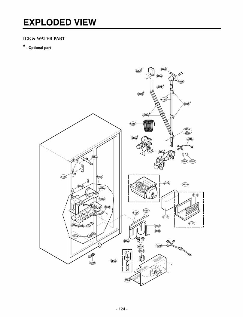
ICE & WATER PART
* : Optional part
EXPLODED VIEW
- 124 -
404B
614A
606A
621B
612A
612B
612C
615A
616B
616C616A
613A
616E
623A*
623Aor
623B
618A
622A
616D*
404A
620A 620B
616A
625A*
616G*
619A*
616F*
627A*
617A
624B
619A*
601A
605A
602A
604A
603B
603A
607A
600A
610A
611B
611A
611C
611D

MACHINE COMPARTMENT
* : Optional part
EXPLODED VIEW
- 125 -
300A310B
307A
304A
306A
310A
317B
317A
305C 305B
313A
301A
306C
307A
104A
305C
305B
303C
303B
303D
303A
305A
410G
500A
502B
502A
406A
101A
101B
308A308C
308B
309B
403B
309C
309A
306C

DISPENSER PART
EXPLODED VIEW
- 126 -
278A
278E
402C
278D
405A
275A 276A
275C
275B
401C
275D
281A
276B
277A
278B
278C
280C
280A
280B
501A
279D
279B
279A
279C
280E
280D
279E
278F

P/No. 3828JD8471B JUN., 2002 Printed in Korea