lindstrand technologies ltd flight manual …€¦ · lindstrand technologies ltd flight manual for...
TRANSCRIPT

LTL TAOM Issue 5.2 Page i
LINDSTRAND TECHNOLOGIES LTD
FLIGHT MANUAL
For use with HiFlyer Tethered Balloons
Lindstrand Technologies Ltd Maesbury Road
Oswestry Shropshire SY10 8HA
TEL: (+44 1691) 671888 FAX: (+44 1691) 679991
All rights reserved. No part of this manual may be reproduced or transmitted in any form or by any means, electronic, or mechanical, including photocopy, recording, or any information storage and retrieval system, without permission in writing from
Lindstrand Technologies Ltd, Maesbury Road, Oswestry, Shropshire, SY10 8HA, England.
LTL TAOM Issue 5.2 Page ii
LINDSTRAND TECHNOLOGIES LTD This Flight Manual has been prepared for the following balloon system: Serial No: Volume: Type Designation: Build Standard: I hereby certify that this Flight Manual and Maintenance Manual (LTL TAOM and LTL TAOM MM), as prepared for the above balloon system and incorporating the amendments listed, conforms to the build standard of the above balloon at the time of delivery. Signed Date: For Lindstrand Technologies Ltd EASA Approval Ref. No. EASA.21J.176 Applicability: Generally, this Flight manual applies to all HiFlyer Tethered Balloons which incorporate a David Brown K830156 winch system. This Flight Manual also covers the use of the LTL-Hydrotechnics winch. The system components which were delivered by Lindstrand Technologies Ltd are identified within the HiFlyer balloon weight sheet on Page iii. All operational limitations which are applicable to the equipment supplied must be adhered to. If any equipment is used within the HiFlyer system which has not been supplied by Lindstrand Technologies Ltd, then the instructions contained within this manual must be regarded as advisory only. It is the responsibility of the operator to ensure that the operational limitations for their hybrid system are established and published. Furthermore, it should be noted that the Lindstrand Technologies Ltd warranty is based upon the exclusive use of Lindstrand Technologies Ltd supplied equipment. Lindstrand Technologies Ltd do not warranty equipment that they have not supplied and the warranty provided on Lindstrand Technologies Ltd equipment which is being operated with components supplied from elsewhere, will be limited.
IF THE HYDROTECHNICS SYSTEM IS USED, PLEASE ONLY REFER TO SUPPLEMENT HYD.WOMM-001 FOR WINCH INFORMATION AND IGNORE ALL REFERENCES TO ANY OTHER WINCHES IN THIS DOCUMENT.
LTL TAOM Issue 5.1 Page iii
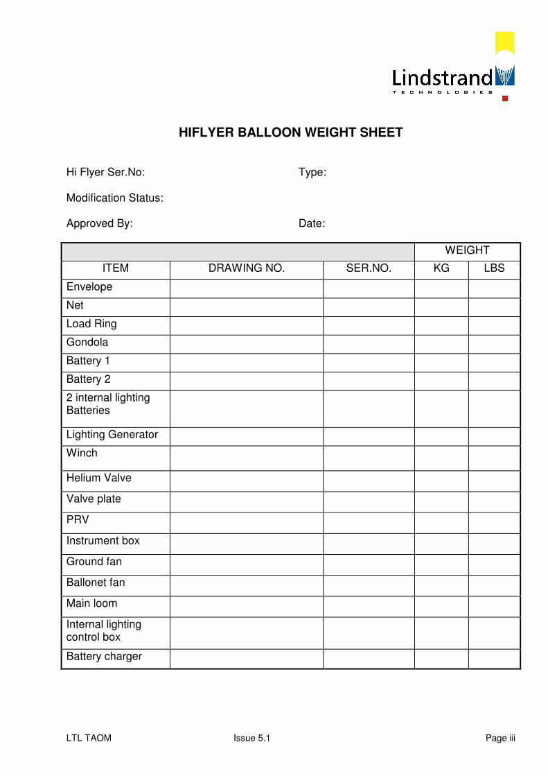
HIFLYER BALLOON WEIGHT SHEET Hi Flyer Ser.No: Type: Modification Status: Approved By: Date:
WEIGHT
ITEM DRAWING NO. SER.NO. KG LBS
Envelope
Net
Load Ring
Gondola
Battery 1
Battery 2
2 internal lighting Batteries
Lighting Generator
Winch
Helium Valve
Valve plate
PRV
Instrument box
Ground fan
Ballonet fan
Main loom
Internal lighting control box
Battery charger
LTL TAOM Issue 5.4 Page iv
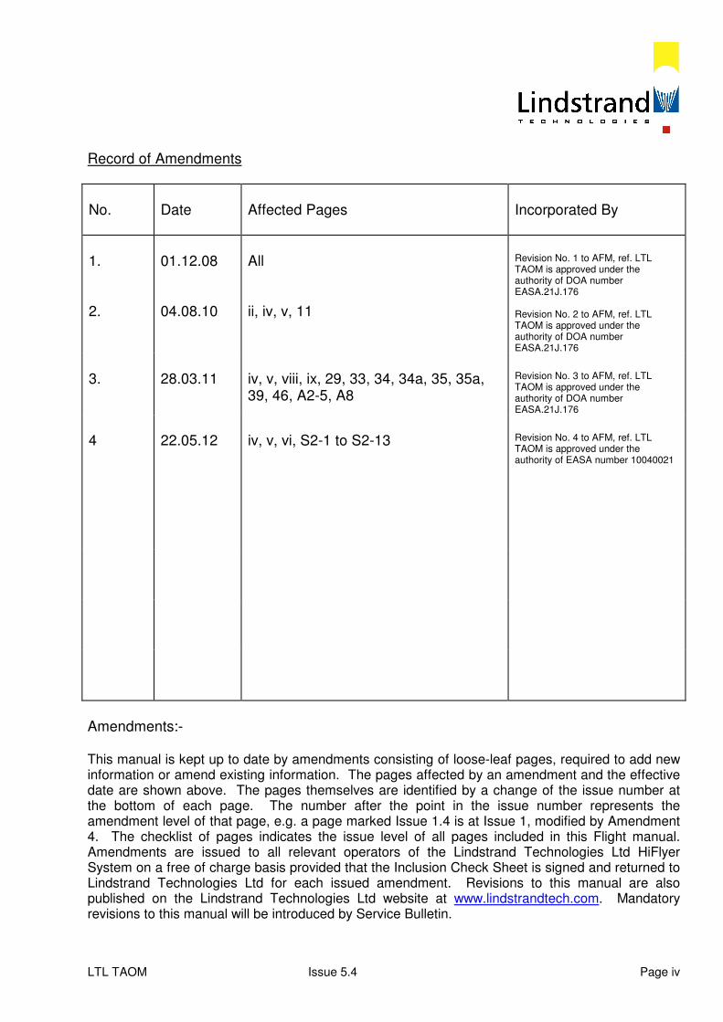
Record of Amendments
No.
Date
Affected Pages
Incorporated By
1. 2.
01.12.08 04.08.10
All ii, iv, v, 11
Revision No. 1 to AFM, ref. LTL TAOM is approved under the authority of DOA number EASA.21J.176 Revision No. 2 to AFM, ref. LTL TAOM is approved under the authority of DOA number EASA.21J.176
3.
28.03.11
iv, v, viii, ix, 29, 33, 34, 34a, 35, 35a, 39, 46, A2-5, A8
Revision No. 3 to AFM, ref. LTL TAOM is approved under the authority of DOA number EASA.21J.176
4
22.05.12
iv, v, vi, S2-1 to S2-13
Revision No. 4 to AFM, ref. LTL TAOM is approved under the authority of EASA number 10040021
Amendments:- This manual is kept up to date by amendments consisting of loose-leaf pages, required to add new information or amend existing information. The pages affected by an amendment and the effective date are shown above. The pages themselves are identified by a change of the issue number at the bottom of each page. The number after the point in the issue number represents the amendment level of that page, e.g. a page marked Issue 1.4 is at Issue 1, modified by Amendment 4. The checklist of pages indicates the issue level of all pages included in this Flight manual. Amendments are issued to all relevant operators of the Lindstrand Technologies Ltd HiFlyer System on a free of charge basis provided that the Inclusion Check Sheet is signed and returned to Lindstrand Technologies Ltd for each issued amendment. Revisions to this manual are also published on the Lindstrand Technologies Ltd website at www.lindstrandtech.com. Mandatory revisions to this manual will be introduced by Service Bulletin.
LTL TAOM Issue 5.4 Page v
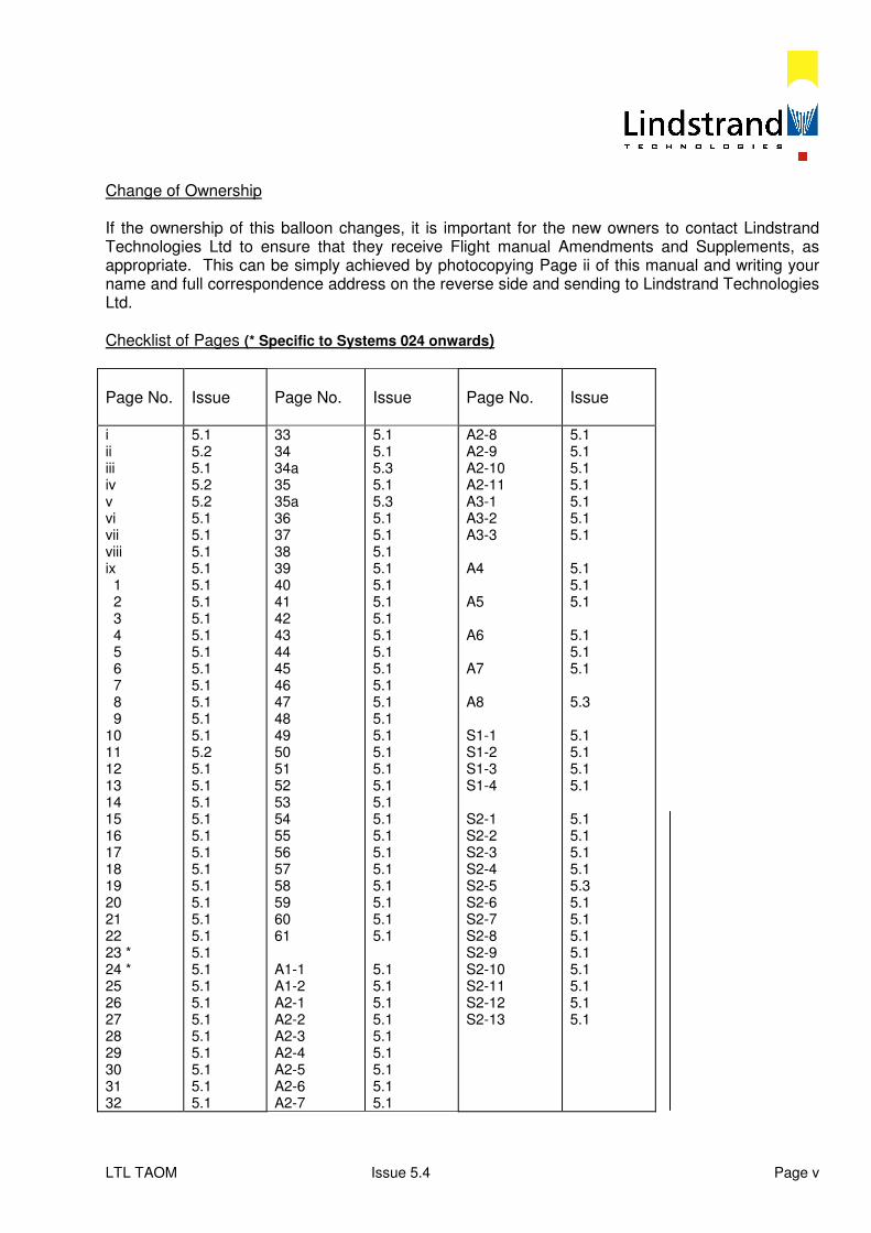
Change of Ownership If the ownership of this balloon changes, it is important for the new owners to contact Lindstrand Technologies Ltd to ensure that they receive Flight manual Amendments and Supplements, as appropriate. This can be simply achieved by photocopying Page ii of this manual and writing your name and full correspondence address on the reverse side and sending to Lindstrand Technologies Ltd. Checklist of Pages (* Specific to Systems 024 onwards)
Page No.
Issue
Page No.
Issue
Page No.
Issue
i ii iii iv v vi vii viii ix 1 2 3 4 5 6 7 8 9 10 11 12 13 14 15 16 17 18 19 20 21 22 23 * 24 * 25 26 27 28 29 30 31 32
5.1 5.2 5.1 5.2 5.2 5.1 5.1 5.1 5.1 5.1 5.1 5.1 5.1 5.1 5.1 5.1 5.1 5.1 5.1 5.2 5.1 5.1 5.1 5.1 5.1 5.1 5.1 5.1 5.1 5.1 5.1 5.1 5.1 5.1 5.1 5.1 5.1 5.1 5.1 5.1 5.1
33 34 34a 35 35a 36 37 38 39 40 41 42 43 44 45 46 47 48 49 50 51 52 53 54 55 56 57 58 59 60 61 A1-1 A1-2 A2-1 A2-2 A2-3 A2-4 A2-5 A2-6 A2-7
5.1 5.1 5.3 5.1 5.3 5.1 5.1 5.1 5.1 5.1 5.1 5.1 5.1 5.1 5.1 5.1 5.1 5.1 5.1 5.1 5.1 5.1 5.1 5.1 5.1 5.1 5.1 5.1 5.1 5.1 5.1 5.1 5.1 5.1 5.1 5.1 5.1 5.1 5.1 5.1
A2-8 A2-9 A2-10 A2-11 A3-1 A3-2 A3-3 A4 A5 A6 A7 A8 S1-1 S1-2 S1-3 S1-4 S2-1 S2-2 S2-3 S2-4 S2-5 S2-6 S2-7 S2-8 S2-9 S2-10 S2-11 S2-12 S2-13
5.1 5.1 5.1 5.1 5.1 5.1 5.1 5.1 5.1 5.1 5.1 5.1 5.1 5.3 5.1 5.1 5.1 5.1 5.1 5.1 5.1 5.1 5.3 5.1 5.1 5.1 5.1 5.1 5.1 5.1 5.1
LTL TAOM Issue 5.4 Page vi
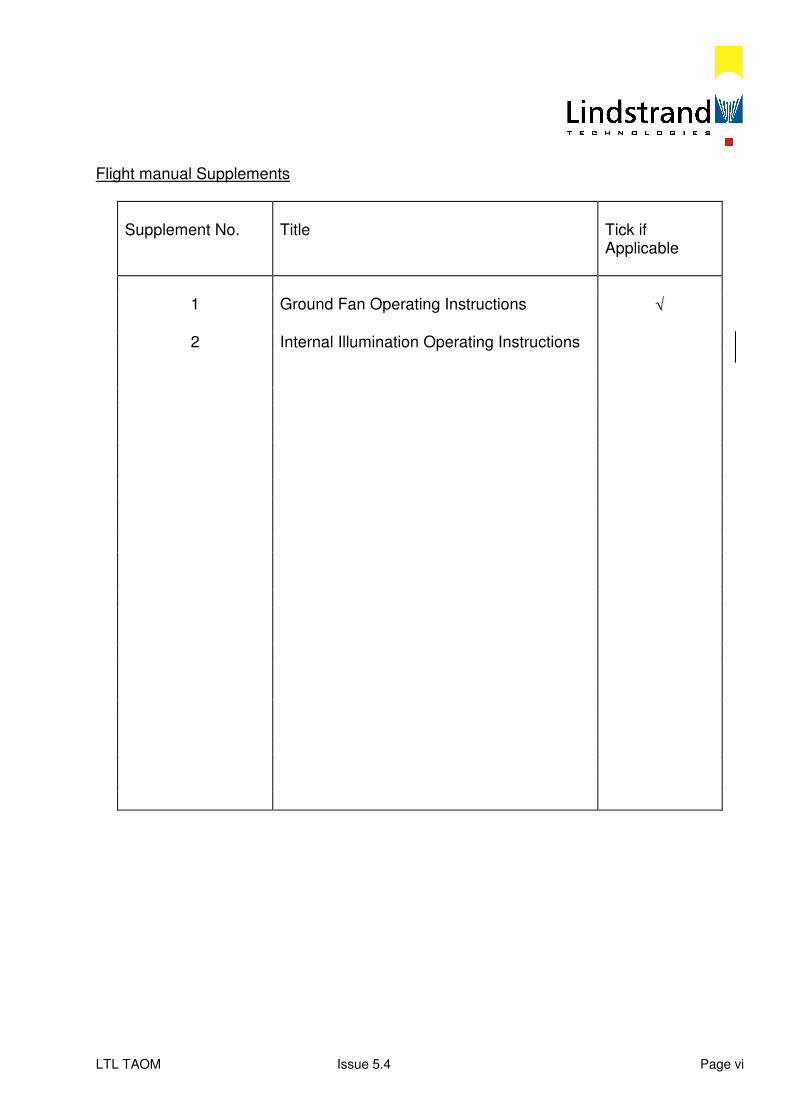
Flight manual Supplements
Supplement No.
Title
Tick if Applicable
1 Ground Fan Operating Instructions √√
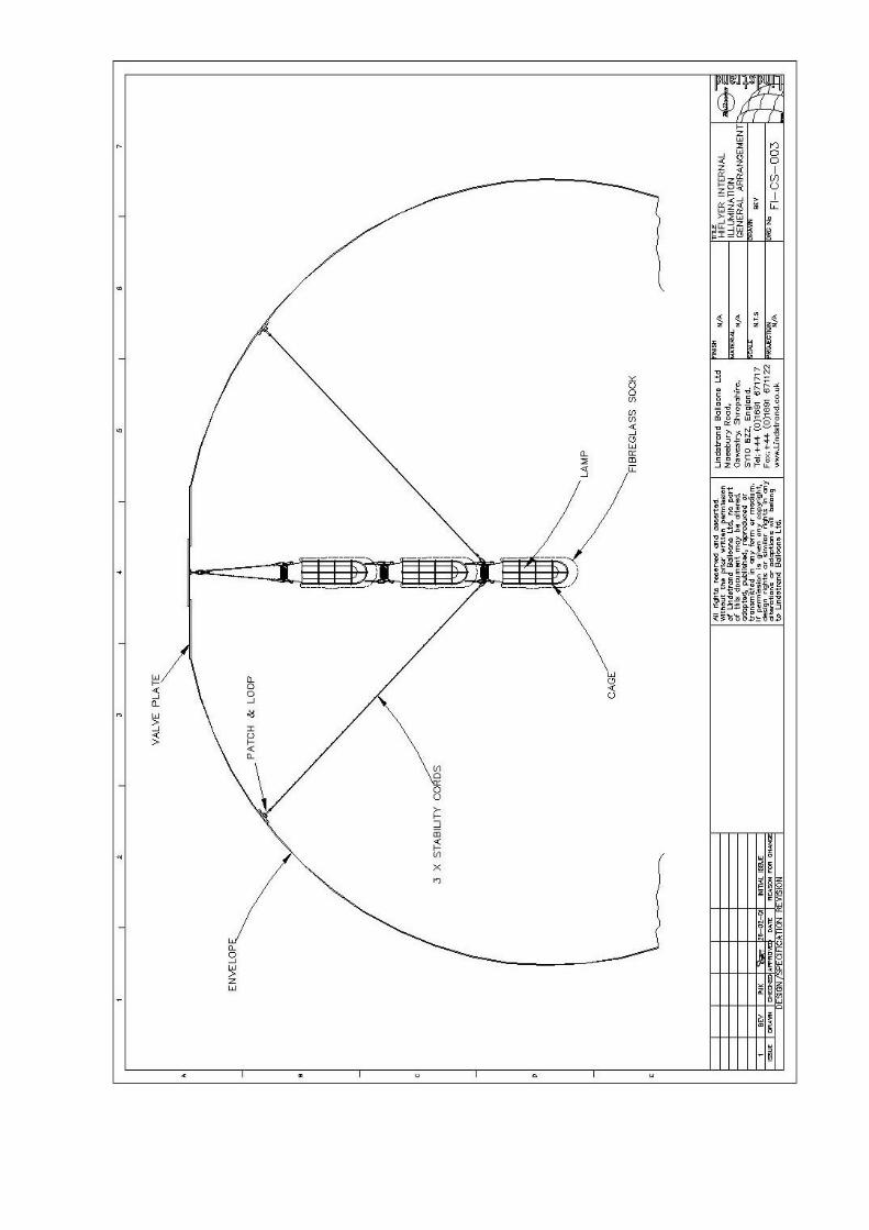
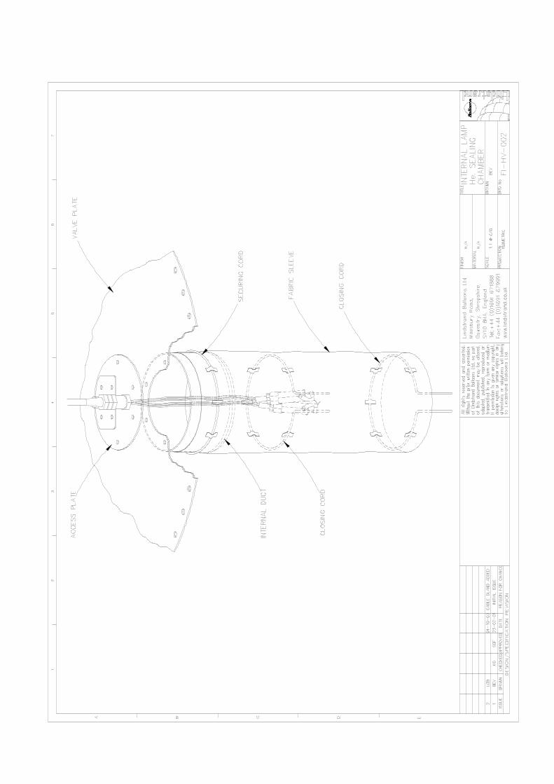
2 Internal Illumination Operating Instructions

LTL TAOM Issue 5.1 Page vii
Statement of Approval This manual forms part of the EASA Type Certificate BA.005 first approved on 4
th March 2005.
Future revisions will require approval, signified by an approval number. Appendices 2, 6, 7 and Supplement 1 are not approved flight manual data and may be revised without approval.
LTL TAOM Issue 5.3 Page viii
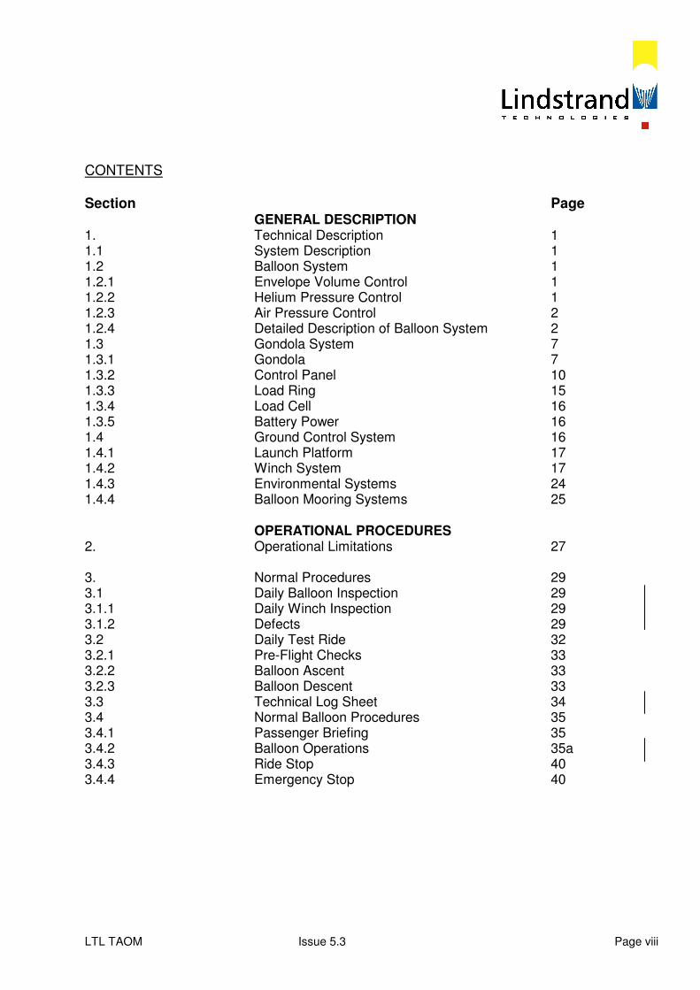
CONTENTS Section Page
GENERAL DESCRIPTION 1. Technical Description 1 1.1 System Description 1 1.2 Balloon System 1 1.2.1 Envelope Volume Control 1 1.2.2 Helium Pressure Control 1 1.2.3 Air Pressure Control 2 1.2.4 Detailed Description of Balloon System 2 1.3 Gondola System 7 1.3.1 Gondola 7 1.3.2 Control Panel 10 1.3.3 Load Ring 15 1.3.4 Load Cell 16 1.3.5 Battery Power 16 1.4 Ground Control System 16 1.4.1 Launch Platform 17 1.4.2 Winch System 17 1.4.3 Environmental Systems 24 1.4.4 Balloon Mooring Systems 25 OPERATIONAL PROCEDURES 2. Operational Limitations 27 3. Normal Procedures 29 3.1 Daily Balloon Inspection 29 3.1.1 Daily Winch Inspection 29 3.1.2 Defects 29 3.2 Daily Test Ride 32 3.2.1 Pre-Flight Checks 33 3.2.2 Balloon Ascent 33 3.2.3 Balloon Descent 33 3.3 Technical Log Sheet 34 3.4 Normal Balloon Procedures 35 3.4.1 Passenger Briefing 35 3.4.2 Balloon Operations 35a 3.4.3 Ride Stop 40 3.4.4 Emergency Stop 40
LTL TAOM Issue 5.3 Page ix
CONTENTS Cont’d
Section Page 3.4.5 Setting Helium Valve Pressure Limits 40 3.4.6 Ground Control Panel Operations 40 3.4.7 High Mooring System 42 3.4.8 Low Mooring System 42 3.4.9 Battery Charging 46 3.4.10 Night Operations 46 3.4.11 Helium Top-Up 46 4. Emergency Procedures 49 4.1 Balloon System Failures 49 4.1.1 Gondola Power Failure 49 4.1.2 Helium Valve Open 49 4.1.3 Ballonet Fan Failure 51 4.1.4 Pressure Relief Valve (PRV) Failure 51 4.1.5 Helium Pressure Exceeds Limit 52 4.1.6 Rapid Free Lift Loss 53 4.1.7 Onboard Fire 53 4.1.8 Helium Overfill 54 4.2 Winch System Failures 55 4.2.1 Remote Gondola Control Failure 55 4.2.2 Power Supply Failure 56 4.2.3 Winch Control Inoperative 58 4.2.4 Main Drive Motor Failure 58 4.2.5 Winch Transmission Gear Failure 58 4.2.6 Winch Pit Fire 60 Appendix 1- Effect of Temperature on Free Lift A1 Appendix 2- Technical Log Record Sheet A2 Appendix 3- Passenger Load Chart A3 Appendix 4- Winch Emergency Recovery Procedures A4 Appendix 5- Special Helium Valve Operations A5 Appendix 6- Diagram of Fabric Sample Locations A6 Appendix 7- Master Minimum Equipment List A7 Appendix 8- Product Report Form A8 Supplement 1- Ground Fan Operating Instructions S1 Supplement 2- Internal Lighting (if applicable) S2
LTL TAOM Issue 5.1 Page 1
SECTION 1 - TECHNICAL DESCRIPTION 1.1 System Description The Lindstrand HiFlyer Tethered Balloon is a system which allows up to 30 passengers and one operator to be lifted to a height of approximately 160m (488 ft) in order to provide an excellent view of the surrounding land. The system is designed to be able to operate in weather conditions which would not be suitable for a hot air balloon flight thus allowing for an increased operational duration and passenger throughput. The system consists of three major sub-systems:- - A balloon and net which provides the necessary lift to support all the
equipment and passenger weights. - A gondola which provides a safe carrying structure for the occupants. - A winch system which allows the balloon to be tethered in position and winched back down at the end of each ride. 1.2 Balloon System The balloon system is the lifting component and is comprised of all the parts which regulate and control the lifting gas. The only lifting gas approved is Helium. The Helium supplied must have a purity of 99.995%. The Helium generates lift due to the fact that it is less dense than the air that surrounds the balloon. The quantity of lift generated is dependent upon the atmospheric conditions and the mass and purity of the Helium contained within the balloon. The balloon is provided with a Helium temperature indicator and a load cell which will give an indication of total free lift. By measuring these two quantities the state of the Helium may be established. The Helium is contained within the envelope which is enclosed by the net which transfers the lift into the load ring and gondola. 1.2.1 Envelope Volume Control The maximum envelope volume is fixed but the volume of helium contained within the envelope will change with changes in the helium temperature, and atmospheric pressure. To accommodate these helium volume changes a separated air filled chamber, called a ballonet, is provided at the bottom of the gas cell. The physical separation is achieved by the presence of a thin fabric membrane between the gas filled cell and the air filled cell or ballonet. The membrane is called the bladder. 1.2.2 Helium Pressure Control The maximum envelope pressure is limited by the strength of the envelope fabric and the weld strength. To ensure that the maximum envelope pressure is not exceeded (40 mm WG) a Helium valve is provided at the apex of the envelope. This Helium valve may be opened to release Helium to reduce the pressure in the envelope. Excessive Helium pressure could cause the envelope to rupture, therefore constant monitoring of Helium pressure is imperative and should be recorded.
LTL TAOM Issue 5.1 Page 2
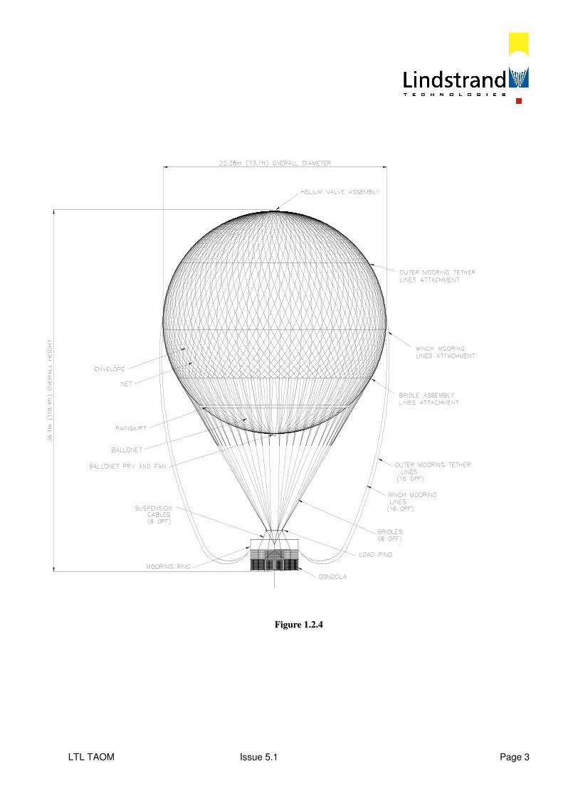
1.2.3 Air Pressure Control As mentioned in Section 1.2.1 changes in atmospheric conditions or Helium temperature cause changes in the Helium volume. If the volume of Helium is reduced due to reducing temperature or increasing atmospheric pressure then the envelope fabric will become slack in the lower portions of the envelope. When the balloon is being operated in windy conditions with insufficient tension in the envelope fabric the fabric will tend to indent. This causes an increase in the drag forces generated by the wind which will cause the balloon to move in a downwind direction. To reduce the drag forces created by the wind it is best to preserve a certain level of envelope tension. This is achieved by introducing an air pressure control system which works in association with the ballonet. At the bottom of the envelope a ballonet fan and pressure relief valve are located. The ballonet fan blows air into the ballonet thus increasing the air pressure in the ballonet. The air progressively fills the ballonet which expands to occupy the space left by the contracting Helium. Once the contracted Helium volume is occupied the fan keeps on filling the ballonet to introduce a small amount of pressure. This pressure is also transferred into the Helium cell through the bladder and results in the exterior envelope fabric being tensioned. This reduces the wind generated drag forces. In association with the ballonet fan a ballonet Pressure Relief Valve (PRV) is fitted next to the fan at the bottom of the envelope. The PRV is set to open at a predetermined pressure of 14 mm (0.55") WG. This ensures that the process of pressurizing the ballonet does not cause the Helium valve to open because of excessive Helium pressure. In normal operation the Ballonet PRV is set to open before the Helium valve. To prevent accidental release of Helium, switch the Helium control valve to manual during storm mooring. 1.2.4 Detailed Description of Balloon System Refer to Figure 1.2.4 for the location of all envelope hardware components. 1.2.4.1 Envelope Description The envelope is manufactured from a heat weldable Helium gas tight fabric. It is a sphere with a diameter of 22.28m (73 ft) giving a total envelope volume, including the ballonet of 5790 m
3
(203,059 ft). The envelope is constructed in vertical segments called "gores". The envelope is reinforced locally by the use of "doublers" for fitment of the various envelope components e.g. helium valve and filler valves. A ballonet is created by the addition of an internal membrane in the lower portion of the spherical envelope. On the outside surface of the envelope in the lower half a fabric drip ring is attached. This provides a measure of protection for the gondola from rain. 1.2.4.2 Ballonet The ballonet is created by separating a volume at the bottom of the main envelope from the gas cell. The boundary is a lighter weight, non-load carrying Helium tight fabric. When the ballonet is fully inflated with air it has a volume of 1,160 m
3 (41,000 ft³).
LTL TAOM Issue 5.1 Page 3
FFiigguurree 11..22..44
LTL TAOM Issue 5.1 Page 4
When the balloon is initially inflated and subsequently topped-up with Helium it is important that the gas envelope is not completely filled with Helium as this will leave no room for subsequent expansion of the Helium. If the Helium cannot expand by contraction of the ballonet the Helium pressure will rise. This may result in operation of the Helium valve, to reduce the Helium pressure, which is a waste of money. Full instructions for obtaining the correct fill level for Helium are contained in Section 3.4.11. On the outer envelope skin, in the lower envelope section a Velcro entry flap is provided. This permits inspection of the condition of the bladder fabric and ballonet fill level. If included, there is a clear ballonet window to assist with ballonet fill level inspection. Note: care must be taken when entering ballonet. This must be supervised and the ground fan must be working so there is plenty of fresh air inside. 1.2.4.3 Helium Valve Assembly and Control Loom The Helium Valve Assembly is situated at the top of the balloon and consists of a flat plate into which is mounted a temperature probe, a Helium valve, a pressure transducer and an access port. On top of the plate is mounted a lightning conductor, white stroboscopic anti collision warning light, a steady position light and a wind speed anemometer. Power and control signals are provided between the items mounted in the valve plate and the control panel in the gondola via a Control Loom. During the inflation the control loom is attached to the net in numerous locations. 1.2.4.3.1 Lightning Protection A collection rod is mounted on the valve assembly plate. The rod is a 1.4m (4.6 ft) long 6 mm (0.24") diameter stainless steel rod with a sharpened tip. Connected to this rod is a high current capacity copper braid, which is incorporated into the control loom. At the lower end of the control loom one wire is connected to the stainless steel load frame. From the load frame there are multiple conduction paths into the main tether rope. Once charge has been conducted down the main tether rope it can dissipate to earth through the winch system. This lightning protection is to prevent the lightning causing damage to the envelope and to avoid injury to the gondola occupants. It is emphasized that whilst the above measures reduce the risks of a lightning strike the best protection is timely prediction of lightning activity and ensuring that the balloon is fully moored and safely grounded during all periods of atmospheric instability. See Operational Limitations 2.1. 1.2.4.3.2 Temperature Measurement The lift created by the Helium varies with changes in the Helium temperature. Consequently it is useful to measure the temperature of the Helium within the envelope. To achieve this a temperature probe is provided within the valve assembly and connected to a read-out which is mounted in the control panel in the gondola. The relationship between Helium temperature and lift is provided in Appendix 1.
LTL TAOM Issue 5.1 Page 5
1.2.4.3.3 Helium Pressure Measurement As described in Section 1.2.2 there is a maximum envelope pressure which must not be exceeded. In order to prevent envelope over pressurization the Helium pressure is monitored by provision of a pressure transducer. This is mounted within the valve assembly at the apex of the envelope
This means that the maximum static pressure within the envelope is measured. The electrical signal from the pressure transducer is fed via the control loom to the control panel. 1.2.4.3.4 Helium Valve The Helium valve is a circular aperture of approximately 355 mm (14") diameter which is covered by a mushroom shaped cap. The edge of the cap seats onto a circular silicone rubber seal which is mounted within the valve ring. A 24v dc linear electric actuator is mounted between the annular ring and the mushroom cap. When the actuator is energized it lifts the cap opening a gap between the annular ring and the cap. Helium is vented through this gap. The process is reversed to close the valve. Two limit switches are fitted to the movement of the actuator which define the upper and lower limits of actuator movement. When the limit switches are reached during the movement of the valve an indicator light, mounted in the control panel lights up. The red light indicates that the valve is open. The Helium pressure transducer and Helium valve operate together to provide an automatic safe pressure limiting system for the envelope. 1.2.4.3.5 Access Port A circular access port is also provided within the valve assembly plate. This port is provided for changing the optional internal illumination light. It is a circular disk of 150 mm (6") diameter held in place by 6 bolts and sealed with a gasket. 1.2.4.4 Pressurization Fan The ballonet fan is located at the bottom of the envelope directly above the gondola. It consists of a ducted 24v dc multi-blade fan which drives air into the ballonet. On the intake side of the ballonet fan is situated a flap valve. This valve automatically closes when the fan is not running to prevent backflow through the fan. The flap valve opens when the fan starts. Power and control signals are supplied to the ballonet fan via a separate loom, which is attached to the main loom. 1.2.4.5 Ballonet Pressure Measurement Ballonet pressure is measured by a pressure transducer which is mounted on the ballonet fan plate. A one metre length of tubing is attached to the pressure transducer to ensure that the pressure that is recorded is not falsely affected by the dynamic airflow from the ballonet fan. The signal from the pressure transducer is fed, via the ballonet fan loom, to the control panel, where it is indicated to the operator. The ballonet pressure transducer and fan operate together to automatically maintain pressure.
LTL TAOM Issue 5.1 Page 6
1.2.4.6 Ballonet Pressure Relief Valve The control valve is located at the base of the balloon, next to the ballonet fan and it is visible from the gondola. It consists of a mushroom shaped cap which seats on an annular sealing ring. The seal is silicon seal. The ballonet pressure control valve is spring loaded and also has an electric solenoid to open at a pre-set pressure level. This pressure setting level is adjusted prior to installation into the envelope. The valve operates automatically and no manual control is required. The normal pressure at which the valve opens is approximately 14 mm (0.55") Water Gauge (WG). 1.2.4.7 Helium Inflation Ports Two inflation ports are provided on the envelope. These are 50 mm (2") bore Monsun Valves; which are mounted on the envelope just above the bladder line, diametrically opposite each other. The Monsun valve consists of a non-return valve which may be locked open for deflation purposes. The filler hose must be equipped with the correct bayonet fitting which matches the Monsun valve. Once filling has been completed the filler hoses are removed and the non-return valve flap is unlocked from the open position. A dust cover is provided for extra security. 1.2.4.8 Helium Replenishment In the course of time the Helium lifting gas will gradually diffuse through the envelope and be lost to the atmosphere. For this reason a method for topping up the amount of Helium is provided. This consists of a small tapping which is situated just above the bladder line, in the helium gas section of the envelope. A pressure hose is attached to this tapping to permit top-up. 1.2.4.9 Internal Illumination System As an option an internal illumination system can be used with the HiFlyer System. This consists of a portable 2.2 Kw petrol generator set which is mounted outside the gondola. Power is transferred up to the valve assembly plate via the main loom which is attached to the net. At the apex of the balloon a connector is mounted on the valve plate which transfers the power into the helium cell where it is fed down a suspension cable attached to the inside of the valve plate, to a cluster of illumination bulbs. 1.2.4.10 The Net The envelope net contains all the lift generated in the envelope and transfers the lift into the load ring. It consists of a series of interlinked ropes, formed into a diamond pattern, which are sized to fit over the envelope. The apex of the net is terminated in a metallic ring which is attached to the valve plate assembly. The bottom of the net connects onto the load ring via 8 bridle rope assemblies. A separate polar rope is provided which runs through the diamond net pattern in the upper half of the net. Attached to this rope are 16 mooring tether lines which anchor the balloon to the outer mooring blocks. Another tether rope is fitted at the equator. This rope is attached to 16 mooring lines which are used for anchoring to the low mooring winches.
LTL TAOM Issue 5.1 Page 7
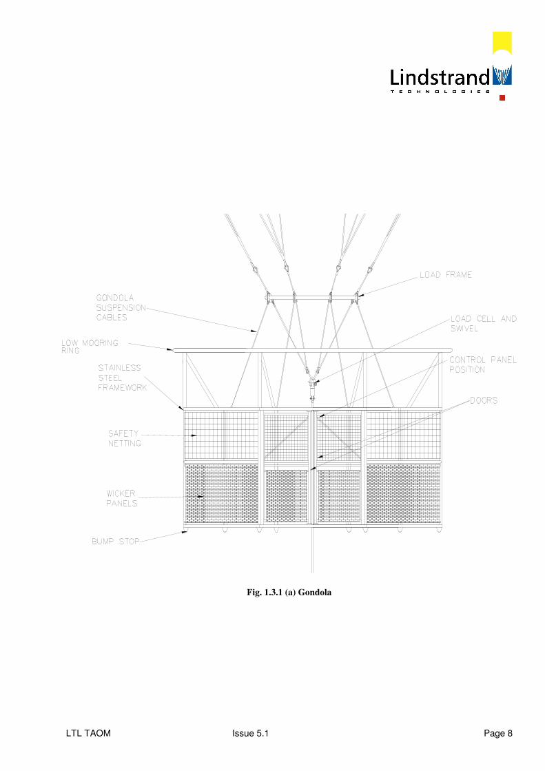
1.3 Gondola System The Gondola system consists of the structure itself, the control panel, the load ring and associated attachments, the load cell and the battery power pack. These items together comprise the means of safely conveying the passengers and operator to the altitude and for controlling the balloon system. 1.3.1 Gondola
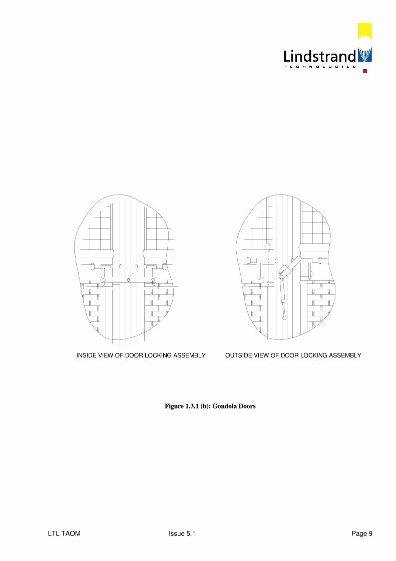
The Gondola consists of an octagonal shaped stainless steel welded framework as shown in Fig 1.3.1 (a). The winch cable passes through the centre space of the gondola. The two gondola sides are spaced 800 mm (31.5") apart, which creates a narrow walkway, sufficiently wide to allow people to pass each other but narrow enough to deter bunching of the passengers at one side of the gondola. The outer faces of the gondola are covered, to just below the handrail, by either woven wickerwork or PVC panels. The inside faces are covered to just below the handrail by double skinned and foam filled polyvinyl panels which are securely fastened in position with over braided "Kevlar" cord. The sides above the handrail and the top face of the framework are covered by nylon netting with a 100 mm (4") mesh size. This netting provides full restraint of the passengers whilst affording good visibility. Two doors are positioned in the outside face of the gondola and open inwards. This means that the doors cannot burst open due to excessive passenger pressure. When both doors are open a triangular space is created which is reserved for the balloon operator. From this position control over the doors, the control panel and battery packs, is achieved at all times. The door handles are situated at the hinge end of the door and a door safety overlock is located on the central pillar between the two doors. Either door can be opened with the other door locked and the overlock open. See Fig 1.3.1. (b). The door latches consist of a solid sliding bolt which requires a double action (lift up and slide) to open them. A single independent overlocking mechanism prevents accidental operation of both door latches. Both the overlock mechanism and the door latches can be operated from inside and outside the gondola. The doors are also equipped with position indicators. If either of the doors or the overlock mechanism are open the red indicator lamp lights up.
LTL TAOM Issue 5.1 Page 8
Fig. 1.3.1 (a) Gondola
LTL TAOM Issue 5.1 Page 9
INSIDE VIEW OF DOOR LOCKING ASSEMBLY OUTSIDE VIEW OF DOOR LOCKING ASSEMBLY
FFiigguurree 11..33..11 ((bb)):: GGoonnddoollaa DDoooorrss

LTL TAOM Issue 5.1 Page 10
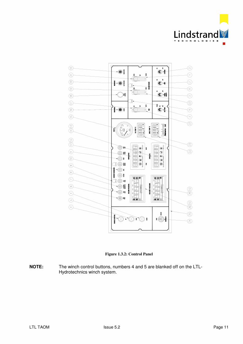
1.3.2 Control Panel The Control Panel is situated on the inside face of the gondola structure, in the triangular space which is created when both of the gondola doors are open. The control panel is housed within a weatherproof box which is mounted on the main gondola structure. Within the panel are housed all of the instruments and switches which are necessary for the monitoring and control of the balloon systems. A schematic drawing of the control panel is shown in Fig 1.3.2. and the numeric references in the following text refer to the item numbers shown on this drawing.
LTL TAOM Issue 5.2 Page 11
WINCH CONTROL
EM.
PWR.
3
SECURITY
UNLOCK
LOCK
DOWN
(mm
WG
)
BALLONET PRESSURE
(mm
WG
)
STOP
UP
52
25
DISP.
HELIUM PRESSURE
PWR.
FAN
FAN
He VALVE
WINCH CTL.
PEAK
RESET
LOAD CELL
TEMP
23
5
NAV.
STROBE
LIGHTS
DOORS
CIRCUIT BREAKERS
22
1 WIND SPEED
WIND
SPEED
LIFT
FREE
LIGHTS
OFF
AMB. TEMP °C
CA
L 3
200
CA
L 3
200
ON
EM. PWR
OFF
FAN
CHECK
AUTO
He TEMP °C
28
VD
O
20
18
24
-+
32
VOLTS
DOORS
ON
WARNING
OFF
CLOSE
OFF
PANEL
NAV
OFF
HELIUM VALVE
ON
AUTO
ON
STROBE
OFF
ON
OPEN
He PRESSURE
MAN
TO TEST
PUSH
WARNING
VALVE OPEN
Figure 1.3.2: Control Panel
NOTE: The winch control buttons, numbers 4 and 5 are blanked off on the LTL- Hydrotechnics winch system.
LTL TAOM Issue 5.1 Page 12
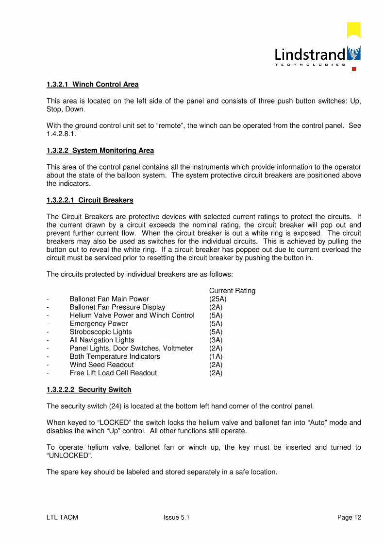
1.3.2.1 Winch Control Area This area is located on the left side of the panel and consists of three push button switches: Up, Stop, Down. With the ground control unit set to “remote”, the winch can be operated from the control panel. See 1.4.2.8.1. 1.3.2.2 System Monitoring Area This area of the control panel contains all the instruments which provide information to the operator about the state of the balloon system. The system protective circuit breakers are positioned above the indicators. 1.3.2.2.1 Circuit Breakers The Circuit Breakers are protective devices with selected current ratings to protect the circuits. If the current drawn by a circuit exceeds the nominal rating, the circuit breaker will pop out and prevent further current flow. When the circuit breaker is out a white ring is exposed. The circuit breakers may also be used as switches for the individual circuits. This is achieved by pulling the button out to reveal the white ring. If a circuit breaker has popped out due to current overload the circuit must be serviced prior to resetting the circuit breaker by pushing the button in. The circuits protected by individual breakers are as follows: Current Rating - Ballonet Fan Main Power (25A) - Ballonet Fan Pressure Display (2A) - Helium Valve Power and Winch Control (5A) - Emergency Power (5A) - Stroboscopic Lights (5A) - All Navigation Lights (3A) - Panel Lights, Door Switches, Voltmeter (2A) - Both Temperature Indicators (1A) - Wind Seed Readout (2A) - Free Lift Load Cell Readout (2A) 1.3.2.2.2 Security Switch The security switch (24) is located at the bottom left hand corner of the control panel. When keyed to “LOCKED” the switch locks the helium valve and ballonet fan into “Auto” mode and disables the winch “Up” control. All other functions still operate. To operate helium valve, ballonet fan or winch up, the key must be inserted and turned to “UNLOCKED”. The spare key should be labeled and stored separately in a safe location.
LTL TAOM Issue 5.1 Page 13
1.3.2.2.3 Monitoring Indicators The following system monitoring indicators are provided:- Item Monitor Readout Units 26 upper Helium Cell Pressure mm WG 26 lower Ballonet Pressure mm WG 12 Wind Speed knots 14 Load Cell Metric Tonnes 23 upper Helium Temperature ºC 23 lower Ambient Temperature ºC 15 Voltmeter Volts The Helium Pressure monitor activates the audible and visual warning at 38 mm WG. The Helium valve automatically opens at a preset pressure of 40 mm WG to protect the envelope. The yellow Helium pressure warning lamp is tested by pushing the adjacent press to test button. The Ballonet Pressure monitor activates the ballonet fan at preset pressure levels. The normal setting level is ‘on’ at 6 mm WG and ‘off’ at 8 mm WG. See Section 3.4.10 for setting instructions. The wind speed indicator (12) incorporates a peak and peak reset button. 1.3.2.3 Balloon Control Area Within the right hand side of the control panel are positioned the switches which control the envelope systems. These are as follows: 1.3.2.3.1 Door Warning Light Item (16 left) lights up if the doors are not closed, or overlock latch is unlocked. 1.3.2.3.2 Ballonet Fan Switch This is a guarded three position switch. When the guard is down, the switch is forced into the down position, which sets the ballonet fan to the automatic operating mode. This means that the ballonet fan operation is controlled by the pressure setting level programmed within the ballonet pressure monitor (26 upper). The ballonet fan will turn off at the set pressure level and will turn on when the pressure level has decreased by 2 mm (0.08") WG. If the switch guard is raised and the switch is placed in the centre off position the power supply is isolated from the ballonet fan. If the switch is moved to the upper manual position the fan will remain running until the switch is moved to another position. The ballonet fan system is secured into “auto” mode by security switch. Before manual operation security switch must be keyed to “unlocked”.
LTL TAOM Issue 5.1 Page 14
1.3.2.3.3 Helium Valve Switches The Helium valve circuit is secured into the “Auto” mode by the security switch. Before the Helium valve switches will operate, the security switch must be keyed to ‘UNLOCKED’. Switches (1) and (22) and indicator light (16 right) are for the control of the Helium valve. Both switches are of the guarded type and when both guards are in the down position the Helium valve will be automatically controlled by the programmed pressure limit in the Helium pressure cell. This means that when the maximum pressure limit is reached the Helium valve will open automatically and will begin to close when the pressure level has dropped 1 mm (0.04") WG. If the switch guard on switch (1) is lifted and the switch raised to the manual position the Helium valve may now be controlled manually by using switch number (22). If the manual Helium valve control switch (22) is operated when switch (1) is in the automatic position nothing will happen. When the manual over-ride switch (22) is down, the valve is in “Auto” mode. When the manual over-ride switch is up to “Manual”, the control switch is active. The valve can now be operated manually. The valve can be isolated by switching the control switch (1) to the mid “Off” position. The valve can be opened by switching up to the open position and holding up. If the switch is released, it will return to the “Off” position and the valve will remain stopped in the open position. The red indicator light will illuminate immediately the valve starts to open and will remain on until it is closed. To close the valve, depress the control switch to the close position and close guard. Ensure red indicator goes out to confirm valve is closed. The red indicator is tested by pushing the adjacent “press to test” button. Note: Returning the over-ride switch to “Auto” or the security switch to “LOCKED” will also close
the valve if Helium pressure is below 40 mm WG. Before operating valve refer to Section 4.1.8 1.3.2.3.4 External Position Lights Three switches (2) all control external position lights. The centre switch will turn on the two steady white navigation lights when in the up position. One of the navigation lights is located below the gondola and can be clearly seen during operation to check that it is alight. The upper navigation light is located on the valve plate and can only be seen from above or from a considerable distance away from the balloon. The right hand switch will turn on the flashing white stroboscopic anti-collision lights which are also located below the gondola and on the valve assembly plate.
LTL TAOM Issue 5.1 Page 15
The upper and lower strobe will flash alternately. To check that the upper strobe is functioning, listen out for the four charging / discharging sounds made by the strobe power unit, located underneath the operators’ floor space. The left hand switch will turn on the control panel instrument lights when in the “up” position. 1.3.3 Load Ring The load ring is constructed from tubular stainless steel with eight equally spaced attachment points. It acts as a junction for all three major system components. The net transfers all the lift generated by the balloon into the upper side of the load ring. The gondola is suspended from the lower outer side of the ring and the main winch cable is attached to the lower inner side of the ring via eight steel wires which converge to a single point situated in the clear central area of the gondola.
LTL TAOM Issue 5.1 Page 16
1.3.4 Load Cell The load cell is a device which is fitted between the confluence point at the bottom of the eight load ring attachment wires and the top of the winch cable. It measures the load applied to the winch cable with the readout located in the control panel (see section 1.3.2.2.2). The range of the load cell is 0 to 10 tonnes (22,000 lbs) with readings in 1 kg (2.2 lb) or 10 kg (22.00 lb) increments. A detachable cable runs from the side of the load cell to the junction box. 1.3.5 Battery Power Power is supplied for all systems from a battery pack which is located on the floor of the gondola. The onboard pack should be charged whenever the gondola is grounded for more than one hour. A spare battery pack is supplied which should be charged up at all times. The pack consists of two 12v dc 65 Amp hour batteries connected in series to produce a supply voltage of 24v dc. All on board systems operate at 24v dc. The pack is fitted with two flying leads; one terminates in a connector to supply power into the control panel when the pack is located within the gondola. The second flying lead terminates in a single connector for the charging unit. When the battery pack is connected to the control panel the voltmeter on the control panel gives a constant indication of the supply potential of the battery. There are four coloured zones on the voltmeter. These zones have the following meanings: Low red arc 18V-20V If the indication is in this sector, the battery must be changed over for the charged-up spare pack and then re-charged. Red and green arc 20V-24 V If the needle drops into this sector when the ballonet fan is operating but is in the green arc when the fan is off, then operations may continue. If the needle moves from the red and green arc into the solid red arc when the ballonet fan is operating, then the batteries require charging. Green arc 24-30 V Batteries are charged normally. Upper red arc 30-32V If the needle moves into this arc the batteries have malfunctioned and should be replaced. If the charging unit is connected, it is faulty and should be replaced. 1.4 Ground Control System The ground control system provides an alternative secure method for controlling the balloon during the ascent phase and for winching the balloon back on the landing platform at the end of the ride.
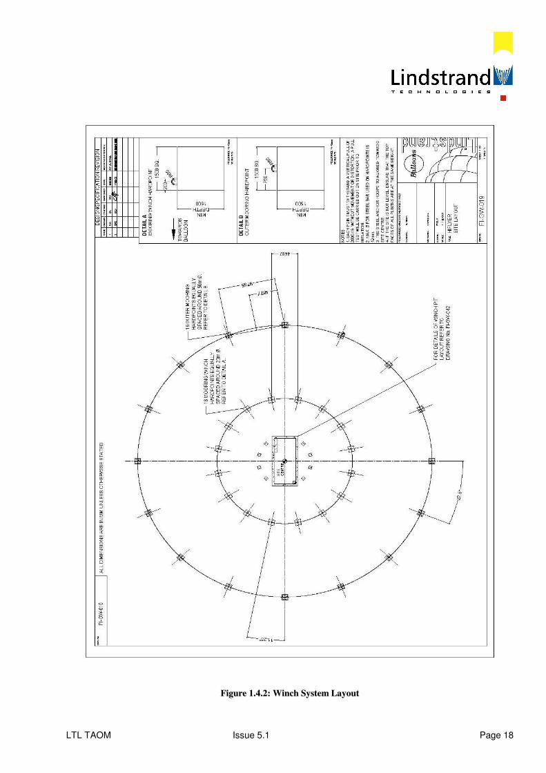
LTL TAOM Issue 5.1 Page 17
1.4.1 Launch Platform The launch platform, if used, is a 12 sided shape with a distance across the flats of 9.0m (29.5 ft). In the centre of the platform is mounted a steel ring of 1m (3.3 ft) diameter, through which the winch cable exits from the winch housing (container, pit or surface mounted housing) to attach to the balloon. The platform consists of a structural steel framework, which is covered with sections of marine ply which create the deck. The marine ply is covered with a non-slip surface. The maximum height of the platform above the ground should be no more 600 mm (24"). The inner end of each segment of the platform rests on the edge of the winch housing container/ pit (underground systems only) and the outer edge is supported by legs. The individual plywood sections are bolted to the steel framework. A hinged access hatch is provided in one of the segments to permit maintenance and servicing. The outer vertical edge of the platform is left open to permit the maximum airflow under the platform and into the winch housing. This is to maximize the winch housing cooling. 1.4.2 Winch System The winch system layout is shown in fig 1.4.2. It consists of the following sub-components: Winch cable Gimbaled sheave Fleeting sheave Main drum Gearbox Main Drive Motor Auxiliary Drive Motor and Gearbox 15 kVA Generator Control Panel Environmental Systems (container, concrete etc) Refer also to David Brown winch operations/ maintenance manual 1.4.2.1 Winch Cable The winch cable is a 22 mm (0.87") diameter die formed 34 x 7 construction steel wire rope which is constructed so that when loaded there is a minimum of rotation created within the rope. At the upper end of the cable there is a conical epoxy bonded end fitting and a swivel which in turn is attached to lower side of the loadcell. At a position approximately 700 mm (27.5") down from the eye of the swaged swivel a 300 mm diameter (11.8") disc is attached around the cable. This disc works in conjunction with a proximity sensor which is mounted on the upper surface of the gimbaled sheave. If the plate approaches closer than 500 mm (19.7") from the sensors then a ‘stop’ is triggered. In addition, two trigger switches are located on the gimbaled sheave. If the plate overrides the sensors and strikes the two switches an emergency stop is triggered.
LTL TAOM Issue 5.1 Page 18
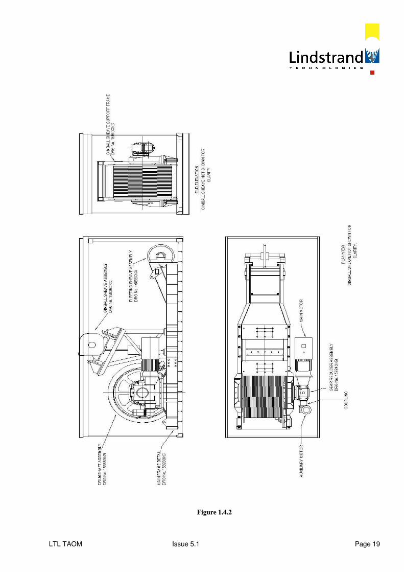
FFiigguurree 11..44..22:: WWiinncchh SSyysstteemm LLaayyoouutt
LTL TAOM Issue 5.1 Page 19
FFiigguurree 11..44..22
LTL TAOM Issue 5.1 Page 20
This protects the sheave from damage. The cable has a breaking load of 42.3 tonnes (93,000 lbs). The lower end of the winch cable is securely anchored to the side flange of the main winch drum using cable clamps. 1.4.2.2 Gimbaled Sheave The gimbaled sheave is a mechanical device which allows the winch cable to move with the balloon wherever the prevailing wind takes it but controls the position of the cable on the winch side so that the cable will be stored correctly on the winch drum. This is achieved by allowing the sheave to gimbal, or rotate independently in two perpendicular axes. The sheave on underground systems is mounted onto the winch frame so that the cable exits the sheave in the approximate centre of the platform. The sheave on surface mounted systems has its own framework which is located in the concrete structure which forms part of the landing platform. Rotational motion of the sheave is dampened by the provision of an underslung weight which is mounted to the sheave frame. As the cable is payed-out the sheave roller moves with the cable. Two electrical counters are mounted on the gimbaled sheave, measuring pay-out of the cable. The information is fed to the control panel and provides the method of altitude control. 1.4.2.3 Fleeting Sheave The fleeting sheave is situated at the opposite end from the main drum. The sheave runs on a threaded shaft. As the cable runs over the sheave it rotates it along the thread. The traversing action feeds the cable into the drum grooves. This arrangement permits the use of a large diameter winch drum within the smallest volume possible. This reduces cable wear and increases simplicity. The sheave has a diameter of 644 mm (25.3"). 1.4.2.4 Winch Drum The winch drum is 1.5m (59") diameter and can hold the whole cable in a single layer. The barrel of the drum is grooved to accept the cable. This ensures that the cable is located correctly and that the contact stresses between the cable and the drum are minimised. The fact that there is only one layer of cable on the winch drum also means that the full tractive effort can be applied over the entire length of the cable and that there are no speed variations during paying out and recovery. One of the drum flanges is fitted with a caliper brake. This is applied automatically. The system is fitted with an overspeed trip which engages the brakes when the payout speed of the cable exceeds the preset safe value of 35 m/min (1.9 ft/s). 1.4.2.5 Gearbox On one end of the winch drum shaft is the gearbox which is a worm/epicyclic unit. This transfers power from the main drive motor to the winch drum, also reducing the motor speed from 1750 rpm down to 7.45 rpm, the speed of the main drum. It can also be driven by the auxiliary drive motor which is located opposite the main winch motor. The auxiliary drive motor is normally de-clutched so that it is not driven by the main drive motor during normal operations. The gearbox is lubricated by a splash oil bath in the lower part of the gearbox casing.
LTL TAOM Issue 5.1 Page 21
1.4.2.6 Main Drive Motor This is a 37 kW (49.5 hp) electric motor which is fed from a local 3-phase supply. The motor is powered through a drive controller. This system controls the acceleration and deceleration of the motor. The changes of speed are imperceptible in the gondola. This system also controls the amount of cable that is payed out automatically. A small VDU is mounted on the winch control panel. The ride height is set between 20 m (65.6 ft) and 160 m (488ft) by pressing the F1 key. The desired maximum gondola height can be preset. The control system is capable of full dynamic braking. This allows the precise control of the payout speeds. The heat created during dynamic breaking is efficiently removed by the cooling system. Heat exchangers are located above the main winch control cabinets. Cooling is assisted by fans mounted within the heat exchanger cabinets. The system is also protected from current overload. If the winch system is jammed by a foreign object, the resultant current overload is detected and the motor off-loaded to protect the drive train. When the gondola is within 1 m (3.2 ft) off the ground the drive is automatically transferred to manual to allow the operator precise control over the speed and timing of final landing. The motor is fitted with a spring operated, fail safe brake which, in the event of a power failure, is engaged on the motor to prevent freewheeling. The maximum tested breaking force is an equivalent of 8 tonnes (17,600 lbs) of cable tension. 1.4.2.7 Auxiliary Drive Motor A 3 kW (4.0 hp) motor is located opposite the main drive motor. It may be manually engaged, through the epicyclic gearbox to drive the winch drum in the event of a total failure of the main drive motor. It should be noted that the auxiliary drive motor can only be used to winch down the balloon. It is not intended to be used for normal ride operations. The motor runs at 1750 rpm into a gearbox which reduces this speed to produce a 0.74 rpm winch drum speed. The power is passed through a manual coupling. This allows the auxiliary motor to be isolated from the main drive motor, when it is not in use. The motor is capable of recovering the balloon at a reduced speed of 3.5m/min (0.2 ft/sec). The controls for the auxiliary drive motor are located on the main control panel within the winch housing. These consist of: a) An auxiliary On/Off button which introduces electrical power to the auxiliary drive motor. b) A Start button which activate the auxiliary motor to drive the winch drum and lower the
gondola. c) A Stop button which stops the motor and winch. It should be noted that there is no automatic stop facility when using the auxiliary drive motor. The stop button must be manually operated when the cable disc is approximately 500 mm above the gimballed sheave.
LTL TAOM Issue 5.1 Page 22
In the event of a mains power failure a 15 kVA diesel driven generator set is provided as a backup power source for the auxiliary drive motor. 1.4.2.8 Winch Controls Balloon operator control of the winch is through use of a radio link remote control unit in the gondola control panel. Primary winch controls are provided in an auxiliary control panel which is located at the edge of the landing platform. This location permits the system to be operated from the ground with a good view of the final landing of the gondola. A main winch control panel is located within the winch housing. This panel contains all the system setting controls. For maximum safety the winch may be controlled from either the radio linked controller or from the auxiliary control panel at any time. It is therefore important for the ground operator to contact the gondola operator prior to controlling the winch from the ground. Two-way radios are used for this purpose. Irrespective of the control point being used, if the emergency stop button is pressed at any of the two control points, this overrides all other inputs. The controls on the radio linked gondola unit and the ground panel are similar in function. 1.4.2.8.1 Remote Control Unit This is incorporated into the gondola control panel. It is linked to the main control panel through an encrypted radio transmission. There are three operational buttons: a) Stop
This button initiates a controlled stop at any time during the ascent or descent. The controlled stop will have the same deceleration programmed response as the automatic stop at the top of the ride.
b) Up Before operation, the security switch must be turned to “UNLOCKED”.
The Up button is pressed once and released. This will start a programmed paying-out of the winch cable. Up to a level of 3 metres the winch accelerates up to a maximum speed of 14 m/min (0.77 ft/sec). When the 3 m point is passed the winch accelerates up to full speed. At a point of 10 m from the pre-set ride height, the winch will slow down until it stops at the ride height. If the ascend button is pressed whilst at the ride height, the command is not accepted. After approximately 10 seconds the main hydraulic brakes are applied to off-load the winch motor.
c) Down
Pressing the Down button starts the descent. When the button is pressed the system latches on and the winch accelerates to its maximum speed. This continues until the balloon reaches a height of 3m (9.8 ft) where it will decelerate down to a stop when 1 m (3.2 ft) from the platform. From this height until landing, the button is non-latching and must be kept depressed to continue winch movement. If the button is not depressed for a period of 8 seconds, then the hydraulic caliper brakes will apply for safety. When the button is next depressed, there is a short delay while these brakes are released.
LTL TAOM Issue 5.1 Page 23
The winch operates at a reduced speed of 14m/ min (0.77 ft/sec), to assist fine control of the gondola during landing. 1.4.2.8.2 Auxiliary Control Panel This is situated at the edge of the landing platform, which permits a good view of the gondola. The majority of controls are identical to the remote control unit controls with the following additions: a) Mains On This lamp lights when mains power is supplied to the winch. b) Local/Remote Key Switch
If it is necessary to control the winch from the ground station, then the key is inserted and turned to “Local”. This disables the gondola remote control unit. Turning the key back to “Remote” returns control to the gondola.
c) Emergency Reset
In order to recommence winch operations after an emergency stop has been used, the emergency stop button must first be pulled out fully at the location it was pressed. Then the emergency reset button, located on either the auxiliary control panel or on the main control panel, must be pressed in order to re-enable the main drive motor and to remove the braking system. If correctly re-set, the red re-set light, located on the main control panel, will illuminate.
1.4.2.8.3 Main Control Panel See Also David Brown Ops & Maintenance Manual (LBLSYS VS009059) This panel, located in the main winch housing, is the primary point for the winch system programming. The following controls are provided: a) System Monitoring Screen
This screen provides information on the system settings gives an indication of the status of the protection devices within the winch and allows the ride height to be adjusted. On the normal mode screen it presents the following:
i) Ride Information
This screen displays Total Rides and Total Rides for the day. The rides for the day can be reset by pressing ‘Reset Rides’. Total rides are left intact. Press ‘Next’ to get Balloon Height 2.
ii) Balloon Height 2
This screen displays Balloon Height 2. There are two sensors measuring balloon height. Both these should be equal. Press ‘Main’ to return to Main Menu.
LTL TAOM Issue 5.1 Page 24
iii) Ride Height Selector
This screen displays Balloon Height. This is also shown by indicator lights above the screen display. Press ‘Next’ to get Balloon Speed.
iv) System Alarms
These screens list all of the protection devices and their status as either healthy or unhealthy. If any item is unhealthy, the screen will flash this item. Corrective action is provided within the David Brown Ops & Maintenance Manual (section 5.5.16). If the alarm is flashing on the top right of the screen, then press ‘LIST’ to see alarms. Using curser keys you can step through alarms. Press ACK on alarm symbol will change (or disappear if alarm has been cleared). Press ‘Exit’ or ‘Main’ to return to Main screen.
b) Mains “On” Light
This light indicates that mains power is being supplied to the system when illuminated. It should go out when the isolator switch is turned off.
c) System Fault
This is a red light and an associated warning buzzer which activates when a system fault is detected. Diagnosis of system faults is provided on the System Monitoring Screen.
d) Supply Source Key Switch
This switch selects whether power is received from the mains or from the 15 kVA generator which should be used with the auxiliary winch motor in order to recover the balloon in the event of a power failure.
e) Emergency Stop and Re-Set
These controls have the same function as their counterpart on the ground winch control point. In order to re-set the system, the emergency button which has been pressed must first be pulled out fully. This prevents the system being re-set without the original fault being rectified.
f) Emergency Recovery Key Switch
If part of the control system fails, or if a protection sensor malfunctions, but the main drive system and brakes are still operational, then this switch may be used to recover the balloon at a reduced speed.
1.4.3 Environmental Systems The environmental systems protect the winch controls and hardware from damage. They consist of the following:
LTL TAOM Issue 5.1 Page 25
1.4.3.1 Winch Housing The winch and all its controls and motors are housed either in a 6m (20 ft) standard ISO container or a concrete pit. If the winch is transported in the complete container, the whole unit is bolted down onto pre-made concrete foundations. The container is waterproofed as far as possible to restrict the ingress of water. A winch support frame carries all the forces from the main drum, fleeting sheave and the gimbal sheave. This support frame in turn transfers the loads into the concrete foundations. The majority of sub-assemblies and the winch container itself, have been protected using Resistex K570. Unpainted metallic surfaces have been treated with Tectyl 506, to resist the formation of rust. If an on-site container is not used, the winch will be shipped in either a crate or container, and simply lowered into the pre-cast concrete pit. The winch is then directly bolted onto the floor of the concrete winch pit, using Lindstrand approved securing mechanism. For surface mounted winch systems, the winch is bolted directly on to a purpose made concrete base, and secured with Lindstrand approved securing methods. 1.4.3.2 Bilge Pump – not supplied The entry of water into the container / pit is impossible to prevent because of the presence of the winch cable exit hole in the landing platform of underground systems. Consequently the container/ pit should be fitted with a bilge pump which is capable of removing 45 l/min (10 gal/min). The water is pumped from the base of the container/ pit and ejected into the local drainage system. The bilge pump is controlled automatically by a float. 1.4.3.3 Fire Extinguishers A standard carbon dioxide extinguisher should be installed within the winch housing to combat any fires, as recommended by local fire regulations (site specific). 1.4.4 Balloon Mooring Positions There are two mooring positions for the balloon, the high and low. The high mooring position is used for restraining the balloon in calmer conditions. When winds in excess of 24 knots are forecast the low mooring position should be employed. 1.4.4.1 Outer Mooring System This consists of a ring of 16 concrete hard point’s equispaced around a circle of 50 m (164 ft) diameter. Spread around the polar rope on the envelope net are 16 ropes which are attached onto the hardpoints using ratchet straps. The ratchet straps are progressively tensioned, to restrict the motion of the envelope. It is important that these are all in equal tension. If outer mooring winches are to be used at the site, then the polar ropes are attached directly onto the winches. These outer mooring winches will be controlled by the same pendant controller that operates the inner mooring winches.
LTL TAOM Issue 5.1 Page 26
1.4.4.2. Inner Mooring System This system comprises a ring of 16 concrete hard point’s equispaced around a diameter of 23 m (70.10 ft). On each hard point is mounted a 1.5 Kw (2 hp) electric cantilevered winch. The 16 mooring ropes are attached to the balloon equator. The ropes are looped over the winch drums and, using local controls on each winch, the slack on the mooring ropes may be taken up. Once equal tension has been achieved the winches may be operated simultaneously in order to lower the balloon down into the lower mooring position. During the descent the load ring is off loaded and it is supported by the bungee cradle. To restrain movement of the lower part of the envelope, 8 load patches are attached to the lower section of the envelope. Lower the envelope to within half a metre above the egg cup ring and attach the 8 apex lines to prevent sideways movement of the envelope and possible damage to the PRV and ballonet fan. Once the envelope is under control it can be lowered onto the mooring ring. Securing lines are attached between the load patch ropes and the anchor hoops on 8 of the mooring blocks. The balloon is lowered for mooring in winds in excess of 24 knots (27.6 mph) and should also be used whenever the qualified operators are not in attendance. It is also moored to be moored over night. The mooring winches are controlled by a pendant controller. This is also provided with an emergency stop button. This emergency stop button only applies to the mooring winches and will NOT affect the main winch system. To reset the system, the emergency stop button must be twisted in a clockwise direction and the ‘Reset’ button pressed.
LTL TAOM Issue 5.1 Page 27
SECTION 2 - OPERATIONAL LIMITATIONS The following operational limitations prescribe the limits of the system. Exceeding these limits may result in a hazardous situation or damage to the balloon system. Other limitations may be placed upon the operation of the balloon by local statutes, or regulations. 2.1 The balloon must not be operated if the load cell is not fully functional. 2.2 The balloon must not be operated in the vicinity of thunderstorms, or unstable weather
including snow storms or carrying excessive amounts of snow. All snow must be removed from the balloon before operation. If severe storms are forecast, the balloon must not be left unattended and all the mooring ropes must be of equal tension.
2.3 The balloon must be securely low moored in winds of speed in excess of 24 knots (44.5
km/hour or 27.6 miles/hour). 2.4 The balloon must be operated by a minimum crew of three. One balloon operator (Level
One), one ground winch operator (Level Two) and one ground operator (Level One). It must not be operated without a Level Two operator on site.
2.5 The balloon ride height (winch pay-out) must be restricted to leave a minimum of 4 full cable
wraps on the winch drum. The ride height must not exceed 160m in any case. Local restrictions may impose a lower elevation.
2.6 The balloon must not be operated with a free lift at the maximum elevation of less than 900
kg (0.9 tonnes). The minimum free lift level is increased with increasing wind speed. See Appendix 3.
2.7 The balloon must be operated with the doors closed and the overlock in the locked position.
The indicator light on the control panel must be out. 2.8 If the balloon is being operated during the periods, defined by the local aviation authorities
as darkness, the anti collision lights and navigation lights must be switched on. 2.9 The balloon must not be operated with an envelope pressure which is greater than 38 mm
WG (1.57"). 2.10 The balloon must not be operated if the indication of battery power falls below 20V. 2.11 The balloon must not be operated if the gondola is loaded such that it produces a hazardous
attitude. 2.12 Smoking is not permitted in the gondola. 2.13 The balloon must not be operated if there is any un-repaired damage revealed by the daily
inspection in Section 3.1. 2.14 The balloon must not be operated with the helium valve open. 2.15 The balloon must not be operated if the pressurisation fan is not fully functional.
LTL TAOM Issue 5.1 Page 28
2.16 The balloon must not be operated if the PRV is not fully functional. 2.17 The daily inspections must be completed and the technical log signed off prior to operations. 2.18 The balloon must not be operated if it has been modified without the written approval of
Lindstrand Technologies Ltd. 2.19 The winch system must be fully operational and tested by a proving ride with one operator only,
prior to commencement of passenger rides. See 3.2. 2.20 Free Lift Limitations - The free lift is measured by a load cell linking the winch cable to the load
ring and must not be operated if this is not fully functional. The free lift indicates the tension at the top of the cable with a readout in tonnes displayed on the gondola control panel.
2.20.1 Operating Free Lift Limits - The operating free lift is the free lift measured when the gondola is
loaded with passengers at its’ maximum ride height.
The minimum allowable operating free lift varies with the peak indicated wind speed at maximum ride height.
Increased free lift is required at increased wind speed to reduce the balloon side drift.
Peak Wind Speed Knots
Minimum Operating Free Lift Tonnes
0 – 5 6 -10 11 - 15 16 - 20 20 - 24
0.90 1.20 1.60 2.20 2.80
Passenger payload must be calculated to maintain minimum operating free lift limitations as above (see Appendix 3).
Increased wind speed encountered during operations will require a reduced passenger load.
2.20.2 The wind tolerance of a storm moored HiFlyer is highly dependent on the topographical
conditions surrounding the site. It has been demonstrated that HiFlyer systems have withstood wind speeds of 61 knots (70 mph or 113 km/hr). If wind in excess of 61 knots is forecast the balloon must be deflated.
2.21 The balloon must only be operated with banners made from approved HiFlyer fabric as
recommended by Lindstrand Technologies. These banners should be fitted accordingly and inspected as part of the pre-flight daily checks.
2.22 The balloon must be operated in accordance with the current Lindstrand Operations/
Maintenance manuals and must not be stopped on it’s accent OR decent more than once.
2.23 The balloon must not be operated if it has been over filled with helium. This could cause the envelope pressure to rise above 40mm WG.
LTL TAOM Issue 5.2 Page 29
SECTION 3 - NORMAL PROCEDURES 3.1 Daily Balloon Inspection The balloon must be inspected daily prior to the test ride, and passenger operation. The inspection follows the procedure itemized in the ‘Daily Balloon Inspection Form’ LTL-TA2 found in Appendix 2 (page A2-4). (Refer to document LTL TAMM, HiFlyer Balloon Maintenance Manual for full balloon system maintenance instructions). When the inspection is completed form LTL-TA2 must be completed, signed and filed. 3.1.1 Daily Winch Inspection The winch must be inspected daily prior to the test ride and passenger operation. The inspection follows the procedure itemized in the ‘Daily Winch Inspection Form’ LTL-TA3 found in Appendix 2 (page A2-6). (Refer to document LTL SYS14, HiFlyer Winch Maintenance Manual for full balloon system maintenance instructions). When the inspection is completed the form LTL-TA3 must be completed, signed and filed. 3.1.2 Defects Any defects found in the Balloon or Winch Inspections must be logged in the ‘Defect Report Form’ LTL-TA8 found in Appendix 2 (page A2-11) and signed. The defects must be reported to the site supervisor and an evaluation against the criteria found in the check sheets and the MMEL, before the balloon is operated. Defects and malfunctions which exceed the stated guidelines should be reported to Lindstrand Technologies Limited on a Product Report Form (see Appendix 8).

LTL TAOM Issue 5.1 Page 30
This page is left intentionally blank

LTL TAOM Issue 5.1 Page 31
This page is left intentionally blank
LTL TAOM Issue 5.3 Page 32
3.2 Daily Test Ride Prior to embarking passengers a proving ride must be conducted with operator only in order to fully test all the sub-systems and to establish the operational limitations for the prevailing weather conditions. Power is introduced to the winch by turning the isolator switch to the on position (clockwise direction). The control system will then run a 30 second test sequence during which, time system information will be displayed on the control screen. After this time, the display will revert to the normal readings. At the completion of the test, the winch remains in the emergency stop condition. The system must be reset by pressing either of the re-set buttons on the main panel or the auxiliary control panel.
LTL TAOM Issue 5.3 Page 33
3.2.1 Pre-Flight Checks a) Charger lead disconnected and removed b) Operator on-board c) Two-way radios present and operational d) Door closed and locked
e) Unladen Freelift within limits – see Section 3.4.11.1 f) Correct ride height set on main winch control panel g) Ground operator on station with a two-way radio h) Daily inspections completed i) Power to the winch is switched on j) Security switch turned to ‘UNLOCKED’ k) Ground control unit set to ‘REMOTE’ 3.2.2 Balloon Ascent The balloon is elevated using the remote control button. The ascend button is pressed once and released. There will be a 5 second delay before the winch begins to move while the brakes are being removed. The first 3 m of motion is at a reduced speed. Once this point has passed, the winch will accelerate up to full speed. 10 m before the pre-set height, the winch will slow down until stopped. Approximately 10 seconds after motion has stopped, the main hydraulic brakes will apply. The ground operator should then contact the balloon operator to inform him that the winch has stopped. Record the required data on the Technical Log Sheet. The ride duration should be approximately 15 minutes to ensure an accurate assessment is made of the prevailing peak wind speeds. Wind speed and elevated free lift with operator only is required to calculate the allowable passenger load. 3.2.3 Balloon Descent Once all observations have been completed, the descend button is pressed. It will latch-on immediately and the winch will accelerate up to its’ maximum speed. When the balloon is approaching the platform it will slow down, coming to a halt at a safe height above the platform. From this safety point, descent is continued by pressing and holding the descend button. If the button is released, the winch will stop immediately. This allows the balloon operator to pause the descent until the wind conditions are the most favourable for a smooth landing. If the descent button is not pressed for 8 seconds, then the hydraulic brakes will apply.
LTL TAOM Issue 5.3 Page 34
If this occurs, then the next time the descend button is pressed, there will be a 5 second delay while the brakes are removed before the winch continues. It is recommended that the button should be pressed every 4 seconds or so during the landing phase. In order to test the functions of the auxiliary ground control panel, it is recommended that this unit is used to control the balloon during the daily test ride, once a week. See Section 3.4.6. 3.3 Technical Log Sheet The Technical Log Sheet LTL-TA1 found in Appendix 2 (page A2-3) (or Tech Log) contains a record of all the prevailing conditions of the balloon system and weather at the start of a day’s operation.
All sections must be completed after the test ride and signed off prior to commencing passenger rides. The following information should be recorded: a) Wind Speed Peak and Average
The peak wind speeds are used to establish the maximum passenger loads in accordance with Appendix 3
b) Ambient Temperature This is recorded from the indication on the control panel. c) Helium Pressure
The Helium pressure is recorded at the top of the ride. If the pressure is close to 40 mm (1.57") WG when the ambient temperature in the morning is cold then the pressure should be monitored carefully as the temperature increases during the day. If it is necessary to vent Helium, this should be done when the balloon is on the ground with no passengers on board.
d) Free Lift
The Unladen Free Lift, with the gondola grounded and the cables slack, must be recorded. This value gives a good indication of the Helium fill in the balloon and is used to track Helium loss rate and Helium top-up requirement. See 3.4.11. The Elevated Free Lift must be recorded on the test ride with the balloon at maximum ride height, with only the operator on-board. This value is used in conjunction with wind speed and operating free lift to determine passenger capacity. See Appendix 3. The Operating Free Lift is the free lift indicated at maximum ride height with passengers aboard and must not fall below the minimum stipulated in limitation 2.18.1. The operating free lift is not recorded in the Tech Log, but should be noted along with the number of passengers for each ride. See 3.4.2.3.

LTL TAOM Issue 5.3 Page 34a
Any defects or damage found on your balloon system at any time should be evaluated for its effect on the continued airworthiness of the aircraft. This may mean reference to the MMEL, MM or FM, or consultation with the manufacturer (Type Certificate holder). The system must be grounded until the damage is repaired or deferred in the proper manner and a Certificate of Release to Service is issued in respect of the damage / defect.
LTL TAOM Issue 5.1 Page 35
3.4 Normal Balloon Procedures Once the daily start up procedures are completed and the Tech Log filled out and signed then passengers may be embarked. The maximum number of passengers to be carried is controlled by limitation 2.19 and is to be determined from the tables in Appendix 3. Embarkation is normally achieved through one door in the gondola to simplify counting of passengers. Once all the passengers are embarked the doors must be closed and latched. This is achieved by pushing the door closed against the door stop. Slide the handle over so that the bolt engages within the pillar. The handle is situated halfway up the door on the hinge side. Once the bolt is correctly engaged rotate the handle downwards so that horizontal motion of the bolt is prevented. When both doors are closed they should be overlocked by swinging the metal bar into the horizontal position. Check the warning light on the control panel has gone out. Continued Airworthiness documentation in the form of Service Bulletins or Service Instructions will only be published on the LTL website, www.lindstrandtech.com. It is the responsibility of the operator to monitor the site regularly to avail themselves of any such documentation which could affect their system. 3.4.1 Passenger Briefing A short passenger briefing should be conducted prior to the start of the ride. It may be conducted prior to embarkation if this is more convenient. It should cover the following points as a minimum: a) Spread evenly around gondola during the ride. Avoid bunching to one side. b) Do not throw anything from the gondola. c) If you feel concern for your well being or feel uncomfortable then inform the operator. He
will terminate the ride. d) Smoking is not permitted anywhere in the gondola. e) Hold onto the handrails on the inner and outer faces of the gondola during take off and
landing. f) Follow any further safety instructions given by the operator.
LTL TAOM Issue 5.3 Page 35a
3.4.2 Balloon Operations 3.4.2.1 Balloon Ascent During normal operations the winch is controlled by the onboard operator. The ascent is started by pressing the 'ASCEND' or ‘Up’ button on the gondola remote control. The button is pressed once and released. There will be a 5 second delay before the winch begins to move while the brakes are removed. The first 3 m of motion is at a reduced speed. Once this point has passed, the winch will accelerate up to full speed. 10 m before the pre-set height, the winch will slow down until stopped. Approximately 10 seconds after motion has stopped, the main hydraulic brakes will apply. The ground operator should then contact the balloon operator to inform him that the winch has stopped.
LTL TAOM Issue 5.1 Page 36
3.4.2.2 Radio Procedures It is necessary for the safe operation of the HiFlyer system that the onboard and ground operators are always in communication with each other. The type of radio used is relatively unimportant provided they are of sufficient power, reliability and clarity and that all local regulations and requirements are met. VHF 720 channel airband transceivers are recommended because of their relatively low signal traffic and for their access to other aviation users and information.
However, it should be noted that the use of these transceivers is controlled and normally will require that the operators hold a licence and that a specific communications channel has to be assigned by the National Airworthiness Authority. In addition, it is normal for the types of transceivers used to be regulated. Early discussion with the appropriate authorities is recommended. The following instructions are intended as a guide to achieve maximum clarity. It is anticipated that these instructions will be translated into the local language. When choosing equivalent words, care should be taken to avoid words which have similar pronunciation, to avoid misunderstandings. For example, using the words ASCEND and DESCEND should be avoided because only the first syllable is different in both words. If a transmission is “clipped” the first syllable will not be transmitted and the recipient will only hear “SCEND”. For this reason, the words UP and DOWN are better. 3.4.2.2.1 Radio Techniques Before transmitting, you should monitor the frequency to ensure nobody else is using it. If both radios transmit at the same time, nothing is understood. Think about what you want to say before transmitting. Keep the length of transmission short and to the point. Ensure that the transmit button is pressed before you start speaking and it is kept pressed until after you finish. This will prevent “clipping” of transmissions. Speak in a normal voice at a steady rate of about 100 words per minute and pronounce each word clearly. 3.4.2.2.2 Recommended Phrases The following phrases are recommended for use and to have the following meanings. If these phrases are translated into the local language and if any additional phrases are used, these should be recorded within the company’s Flight manual for future consistency when training new operators. UP - I have pressed the ASCEND button
LTL TAOM Issue 5.1 Page 37
WINCH STOPPED - The winch has stopped moving and the brakes have been applied (Ground Operator)
DOWN - I have pressed the DESCEND button STOP - I have pressed the STOP button EMERGENCY - I have initiated an emergency stop (Ground Operator) RESET - I have reset the winch system and you have control of
the winch (Ground Operator)
OVER - My transmission is ended and I expect a response from you
OUT - My transmission is ended and no response is expected NEGATIVE - No, or that is not correct AFFIRMATIVE - Yes, or that is correct SAY AGAIN - Repeat all or part of your last transmission 3.4.2.2.4 Gondola Remote Control Unit Failure If the gondola remote control unit fails and the balloon operator has contacted the ground operator in order to initiate a descent using the auxiliary control panel, it is important that the transfer of control is clear and unambiguous. Once the ground operator has selected local, they should contact the balloon and transmit “GROUND HAS CONTROL”. Once informed of this, the balloon operator understands that the remote control unit is completely disabled. If the balloon operator wishes to initiate an emergency stop during this recovery, they should transmit “EMERGENCY, STOP”. Upon hearing this, the ground operator will press the emergency button on the auxiliary control panel. If control is reverted to the balloon, the ground operator should transmit “BALLOON HAS CONTROL”. 3.4.2.2.5 Radio Failure If radio communications fail for any reason so that the messages cannot be passed, then the ride should be completed to the normal duration pattern. Once the balloon has landed, the radio failure must be corrected before rides recommence. In the unlikely event of both the gondola remote control unit and the balloon radio failing simultaneously, the balloon operator should be equipped with either a loud whistle or air horn. These should be used to attract the ground controllers’ attention with three short blasts. On hearing this alarm signal, the operator should proceed with a recovery using the auxiliary local controls. It is recommended that the ground operator should monitor the ride duration and if the ride time is longer than 30 minutes, they should firstly try to establish radio communication with the balloon. If this is not possible, they should then proceed with a recovery using the auxiliary controls. This is to cater for the possible incapacity of the balloon operator.
LTL TAOM Issue 5.1 Page 38
3.4.2.3 Balloon Monitoring While the balloon is being operated the operator should monitor the following systems: a) Helium Pressure
As the balloon ascends the atmospheric pressure will reduce by approximately 1.4%. This causes an expansion of the Helium in the balloon. The expansion of the Helium will normally be accommodated by the air filled ballonet reducing in size. However, if the Helium cell has been overfilled and the ballonet volume is minimal prior to the ascent then there may be a possibility that there is insufficient space for the Helium to expand.
This will result in the Helium pressure increasing as the balloon ascends. If the pressure exceeds the warning level, the Helium audible and visual alarms will set off and the Helium valve will begin to open. The operator should monitor the Helium pressure during the rides to ensure this situation does not occur. If the Helium pressure is rising too much then the ascent should be stopped and the balloon lowered down to the platform. Investigate the reason for the excessive Helium pressure and correct this. This will normally consist of a controlled opening of the Helium valve to vent some of the helium.
b) Helium Temperature
When the balloon is being operated in sunny conditions the envelope absorbs heat and the emperature of the Helium will gradually increase above the ambient temperature. This difference in temperature between the ambient and the Helium temperatures is called Superheat. Normally the extra heat will cause the Helium to expand and the ballonet volume will reduce to accommodate this. However, similar to the above case if there is insufficient room for expansion of the Helium the pressure will begin to rise and Helium may be vented. Both an ambient air temperature probe and a Helium temperature probe are provided so that the amount of superheat can be monitored, along with the Helium pressure. 15ºC (59ºF) of superheat is not uncommon.
c) Operational Free Lift
The operational free lift is the lift that is indicated on the load cell readout when the balloon is being operated with passengers. The maximum number of passengers that may be embarked is established at the completion of the test ride - see Appendix 3. However it is the responsibility of the operator to adjust the maximum number of passengers in response to changing conditions within the operational limitations of the system. If the wind speed increases or slackens then the maximum passenger load must be modified so that the minimum operational free lift requirements are met. It is recommended that the load cell indicator is reviewed just after each ascent phase has started to ensure that the free lift figure is not below the required levels. For example is the wind speed is 3 knots the minimum free lift is 900 kg.
LTL TAOM Issue 5.3 Page 39
The operator is also responsible for reviewing the embarking passengers. The maximum number of passengers is based upon an average passenger weight of 77kg (169 lbs). If the embarking passengers are obviously heavier than this figure, the operator should reduce the maximum number embarked. d) Weather
Before the day’s operations commence a meteorological forecast must be obtained with particular reference to wind speeds and directions, expected precipitation and any thunderstorm activity. This information must be entered on the Technical Log Sheet. In addition the wind speed display should be monitored during each ride. If the wind speed increases then the maximum passenger figure must be reduced to remain within the limitations given in Appendix 3. Increasing wind will tend to drag the balloon in the downwind direction. The greater the free lift the more the balloon will stay vertical and the more comfortable the ride will be for the passengers. The main method for increasing the free lift is to reduce the passenger load.
For operations at higher wind speeds it is important to ensure that the ballonet pressure is maintained. If the ballonet pressure is not maintained then the envelope will become slack and the drag forces will increase. This will cause the envelope to move downwind. Care must also be employed when operating in gusty wind conditions. If the peak wind speed are significantly higher than the mean wind speed the motion of the gondola increases. This may be distinctly uncomfortable for the passengers. This effect may be reduced by decreasing the passenger load. The peak wind speeds are obtained from the wind speed indicator by pressing the peak button on the display.
With experience the operator should be able to notice changing weather patterns and to plan the day's operation based on this knowledge. A basic course in meteorology is strongly recommended for all operators. Attention should always be maintained to spot approaching squalls. If the balloon becomes wet the free lift can quickly be reduced by 200 kg (440 lbs) because of the weight of the water on the envelope and net. Other than this reduction in free lift the system is capable of being operated in the wet if the passengers should so desire.
3.4.2.4 Balloon Descent The descent is started by pressing the “DOWN” button on the gondola remote control unit. The button will latch on immediately and there will be a 5 second delay while the hydraulic brakes are released. The winch will then accelerate for 5 seconds up to 50% of the maximum speed. It then accelerates to full speed. When the balloon is approaching the platform it will slow down, coming to a halt at a safe height above the platform. From this point until the gondola is grounded, the descent is continued by pressing and holding the descend button. If the button is released the winch will stop immediately. This allows the operator to pause the descent until the wind conditions are more favourable for a smooth landing. If the descend button is not pressed for a period of 8 seconds, then the hydraulic brakes will be applied. If this occurs, then the next time the descend button is pressed, there will be a 5 second delay while the brakes are removed before the winch continues. It is recommended that the button should be pressed every 4 seconds or so during the landing phase.
LTL TAOM Issue 5.1 Page 40
It is important to ensure that when the gondola is grounded, the disc situated at the upper end of the cable is within 500 mm of the sensors mounted on the gimbaled sheave. This process resets the ride height to zero after each ride to ensure that accumulative measurement errors are not introduced into the drive programme. 3.4.3 Ride Stop If, for any reason the ride has to be stopped before it reaches the normal ride height the stop button should be pressed unless there is an emergency (see following section). Depressing the stop button will override the programmed ride profile and initial an immediate controlled deceleration and stop. 3.4.4 Emergency Stop The emergency stop button may be pressed at either of the two control panel locations and this will over-ride all other ride programs. It is intended for use only when to continue winch motion would cause a hazardous situation for any person or if structural damage is imminent. All system braking is used to bring the winch and also the balloon to a halt, as quickly as possible. This will produce a noticeable jolt in the gondola, which may cause passenger discomfort. If possible, in the available time the passengers should be warned to hold onto the handrails firmly and to brace themselves. Once the emergency stop has been used the button must be pulled fully out and the emergency reset button must be pressed on either the main or ground control panels, in order to reset the system. The system cannot be reset from the gondola remote control. 3.4.5 Setting Helium Valve Pressure Limits The Helium valve pressure limit is factory set. Lindstrand Technologies Ltd must be consulted prior to any alteration of this settings. Unauthorised adjustment could cause envelope failure. 3.4.5.1 Setting Alarm Pressure This pressure level may be changed to accommodate any specific requirements the operator may have for advanced warning of the valve opening. However it is recommended that no changes are made to this level until the system has been operating for at least 1 month on site, to fully establish the necessity for change and the most effective new pressure level for the alarms within the local operating microclimate. Similarly the factory must be consulted prior to changing the alarm pressure level. 3.4.6 Ground Control Panel Operations If the “remote” gondola control fails, it will be necessary to recover the balloon using the “local” ground control panel. The ground operator must first inform the balloon operator of the transfer of control, as described in Section 3.4.2.2.4. Then the key is inserted into the switch marked LOCAL / REMOTE and turned to LOCAL. This disables the remote control completely. The remainder of the controls on the “local” ground control panel have identical functions as those described for the remote control. Control of the balloon is returned to the “remote” control by turning the keyswitch back to the REMOTE setting.
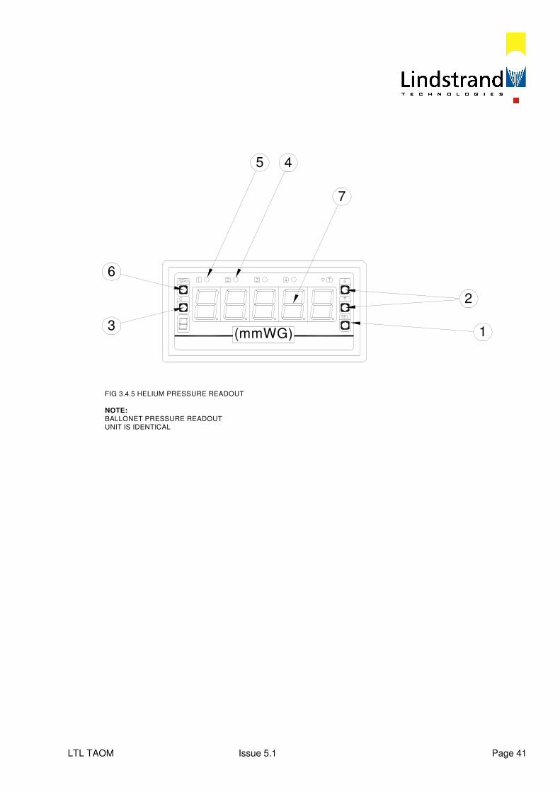
LTL TAOM Issue 5.1 Page 41
(mmWG)
2
1
7
45
6
3
FIG 3.4.5 HELIUM PRESSURE READOUT
NOTE:
BALLONET PRESSURE READOUTUNIT IS IDENTICAL
LTL TAOM Issue 5.1 Page 42
3.4.7 High Mooring System This system is used for mooring the balloon for short periods of time when the wind is not greater than 24 knots (27.6 mph) and if operations are going to continue later in the day. The 16 outer mooring ropes attached to the polar rope around the upper part of the net are stowed on the outside of the gondola. To high moor the balloon, the ropes are released one at a time from the gondola and attached to ratchet straps anchored to the 16 outer mooring blocks. Each rope is attached to the nearest ratchet strap with a karabiner to the highest rope loop within easy reach and then tensioned down. This process is repeated for all 16 mooring ropes. Once all the mooring ropes have been attached, the ratchet straps may be further tightened if necessary. Care should be taken to ensure that when completed, the tension in each of the mooring ropes is equal. Where there are extra outer high mooring winches the mooring ropes will be looped directly around the high mooring winch drums. The ropes will be wound on individually on each winch until they are at the same tension as the other mooring ropes. If the wind is strong enough to move the balloon whilst trying to attach the mooring ropes, it is best to first secure the mooring ropes situated 90º to the general wind direction. These ropes can be tensioned to restrict the balloon’s motion. The two adjacent upwind mooring ropes should then be attached and similarly tensioned to further reduce the envelope motion. Continue this process until all the upwind mooring ropes are attached and then repeat the process with the downwind ropes. When all the outer mooring ropes are attached, connect and tension the low mooring ropes. The 16 low mooring ropes attached to the net equator rope round the middle of the balloon are stowed on the outside of the gondola. Release the ropes and loop around the winch drum so that winching down will tension the loop. Set the mooring winch pendant control to “one” and “lower”. Tension each rope one at a time and ensure that all ropes have equal tension. Tighten outer mooring straps again. The balloon is now high moored. See HiFlyer Training Manual, Volume 1, for detailed procedure. 3.4.8 Low Mooring System 3.4.8.1 Mooring Procedure This form of mooring is used whenever the expected winds are in excess of 24 knots (27.6 mph) or for overnight mooring.
LTL TAOM Issue 5.1 Page 43
In order to low moor the balloon, it must first be in the high moored position, as described in Section 3.4.7. Before low mooring, confirm all winch ropes are under equal tension. a) Switch the Helium valve to “Manual” to prevent accidental operation of the valve if the
pressure in the envelope rises as it is pulled down onto the mooring ring. b) Switch the winch control pendant to “All” and “Lower”. c) Winch the balloon down with all mooring winches simultaneously until the bottom of the
envelope is within 500 mm of the gondola mooring ring and stop.
As the balloon comes down, the outer mooring ropes will slacken and allow the balloon to move around in the wind. Where there are extra outer mooring winches, these will steady the balloon as it comes down. If outer mooring winches are not used to stabilize the envelope, it may be necessary to fasten the outer straps to higher loops on the outer mooring ropes and re-tension the ratchets, at the same time centering the PRV and ballonet fan inside the mooring ring.
d) Attach the 8 lower apex mooring straps to the rope extensions on the bottom of the
envelope to restrict the movement of the PRV and fan and prevent damage by contact with the mooring ring.
The apex mooring straps are anchored to alternate mooring winch blocks and passed over
the top of the gondola mooring ring and connected to the envelope load patch rope extensions with karabiners.
Tension the ratchets to secure the envelope. e) Lower the envelope onto the mooring ring until it indents the envelope approximately
500 mm, to prevent shuffle. f) Ensure that all securing ropes are of equal tension. g) Once the balloon is secure and ready for the weather, the main winch controller must be
switched off. h) Switch the Helium valve back to “Automatic”, except under the following conditions: In extreme weather, the Helium valve should be left on ‘Manual’ as the Helium pressure will be artificially increased by the buffeting of the wind and the pressure could rise above the operating limit of 40 mm WG. The Security Switch must be in the ‘UNLOCKED’ position to operate the helium valve in the ‘Manual’ position. Note that when the balloon is moored when there are thunderstorms in the local area, the mains power should be switched off at the main external circuit breaker and personnel must not enter the winch housing or approach any metallic components of the balloon or associated rigging.
LTL TAOM Issue 5.1 Page 44
3.4.8.2 Storm Mooring Procedure This is the most secure form of mooring when winds in excess of 35 knots are forecast. In addition to low mooring, the following precautions must be taken: a) Mooring Cushions
The 8 inflatable mooring cushions should be attached to the gondola to provide extra contact area for the envelope. The cushions should be inflated with the air blower supplied and attached to the gondola using the ratchet straps provided, before the balloon is finally lowered onto the mooring ring.
b) Gondola Anchoring
The gondola should be secured in 8 positions, with 5 tonne ratchet straps running from the corners of the gondola, at hand rail height, to the steel hoops on alternate inner mooring winch blocks.
c) Ground Fan The ground fan has a higher pressure and flow rating than the ballonet mounted fan.
This speeds up envelope pressure recovery under gusty conditions and reduces envelope distortion and wind drag.
The ground fan should be installed on the decking, with the hose connected to the ballonet fan inlet. Electrical power must be plugged in and the control system electric connection made. Operating instructions are contained in Supplement 1.
The ground fan must be disconnected before the balloon is raised or operated. 3.4.8.3 Unmooring Procedure The unmooring procedure is largely the reverse of the mooring procedure and involves two basic procedures: - High Mooring from Low Mooring Position - Operational Position from High Mooring Position High Mooring from Low Mooring Position: - Remove the outer mooring lines from the ratchet straps and reconnect to the last loop. If
outer mooring winches are supplied, keep the tension the same as with the inner mooring winches, so that all winches raise the balloon at the same time.
LTL TAOM Issue 5.1 Page 45
- Take two turns through the ratchet, ready to re-moor if necessary. - Remove lower apex straps and gondola securing straps if fitted. - Switch mooring winch controller to “All” and Raise”. - Switch helium valve to “Automatic” on gondola control panel. - Check all securing ropes are in their correct position. - Raise balloon whilst observing the load ring and load cell for any entanglement. - As the balloon picks up the main winch cable check that the cable is running through the
correct path. The load cell will start to read and the free lift will rise. As the lift increases, stop raising the balloon.
- Remove storm mooring cushions if fitted. - Re-tension outer and inner mooring lines if the balloon is to be held in high moored position. Ride Ready from High Moored Position: - Switch on main winch system. - Remove tension from outer mooring ropes and keep secured to outer mooring position
allowing enough slack for the balloon to rise to the operational position. - Switch mooring winch pendant controller to “All” and “Raise”. - Raise balloon until ropes slacken. - Remove inner mooring ropes and stow on outside of gondola. - Remove outer mooring ropes and store on outside of gondola. - Lay out ratchet straps with two turns through buckle, ready for re-mooring. - Switch mooring winch pendant controller to “One” and “Lower”. - Record unladen (grounded) free lift. - Balloon is now in the operational position. - Commence pre-ride checks.
LTL TAOM Issue 5.3 Page 46
3.4.9 Battery Charging A battery pack must be connected to the control panel and have sufficient charge at all times whilst the balloon is inflated. This is to keep the Helium pressure control system operating and the ballonet fan working. A battery charger is supplied so that whenever the gondola is moored the power pack should be charged. During a long day of operations charging should be achieved during the day in between rides to maintain the battery charge level. A second battery power pack is supplied, to be kept fully charged and available to exchange with the onboard unit, should that unit loose its power. The battery charger lead connects to either connector lead from the battery pack. Only the battery charger supplied should be used. Using a standard 24Vdc charger will reduce battery life. 3.4.10 Night Operations Provided local permissions have been secured and the correct navigation lights are fitted and working the balloon may be operated at night. However care must be used when operating at dusk. The temperature drop can be quite rapid as the sun goes down and this has a major effect on the free lift. As the Helium temperature drops the passenger load must be reduced to maintain the minimum operating free lift. The landing platform should be well illuminated with flood lights to assist the operator in judging the landing. 3.4.11 Helium Top-Up During normal operations, Helium will permeate through the gas balloon envelope. This slowly results in a loss of free lift. When the unladen free lift drops to the lower recommended level, the Helium should be topped up. This is carried out when the balloon is in the low moored position. Turn the Helium valve to manual. It should then be returned to the operational position once the top-up is complete. A top-up hose is fitted into the helium cell and runs down towards the gondola. The hose terminates in a
3/8” Tema connector, where it is accessible from the ground.
A supply hose is connected from the high pressure Helium gas cylinder to the top-up hose with the mating Tema coupling. The gas cylinder valve should have a regulator fitted (not supplied by LTL) and is opened to 50 psi until the cylinder is exhausted. Further cylinders can be connected in turn until the unladen free lift reaches the desired level. The position of the internal bladder may be checked through the Velcro access flap provided in the exterior ballonet skin or the clear viewing panel if fitted. The amount of Helium put into the balloon should be carefully judged. It is important that the balloon is not overfilled, such that there is insufficient expansion volume remaining within the ballonet to accommodate changes in Helium volume as temperature rises.
LTL TAOM Issue 5.1 Page 47
Start to fill the envelope with the Helium, but observe the position of the bladder regularly. If the bladder position indicates that the balloon is becoming full, then stop the Helium supply. This situation may occur when the Helium within the envelope has become impure. Air eventually enters the envelope and dilutes the Helium. This will result in there not being sufficient room within the envelope to accommodate the Helium required to restore the free lift. Whilst filling with Helium, the ambient temperature level should be monitored. If the temperature is low, it is more important to ensure that sufficient expansion volume remains within the envelope. If in doubt, it is better to underfill rather than overfill. The Helium may be purged pure again. Consult Lindstrand Technologies if the Helium requires purging. Once Helium filling has been completed, disconnect the Helium fill hose and return to service. Complete the Technical Log with the final amount of Helium put into the balloon. For reference, the sea level lift of Helium gas is approximately 1 kg/m³. A high pressure Helium cylinder of 50 litres capacity at 200 bar pressure would contribute approximately 9 m³ of free Helium and 9 kg of free lift when discharged into the envelope. 3.4.11.1 Helium Fill Level The Helium fill is controlled by the envelope and ballonet capacity. The Helium cell should be filled with Helium until half the ballonet volume is displaced, with the bladder in the mid position. Ideally, the fill should be measured at average local operating temperature, so that both expansion and contraction of the Helium cell with rise and fall in temperature can be accommodated. The fill level can be measured in terms of free lift, as this is directly related to the volume and purity of the Helium gas. This can be measured by the load cell on the balloon system, displayed at the control box. The free lift used as a basis for the Helium fill level is the unladen free lift, that is the free lift with the balloon raised so that is restrained by the winch cable with the load cell under tension, but with the gondola on the deck with the cables slack. The unladen free lift will measure the lift of the Helium less the weight of the balloon assembly (envelope, net and load ring). As the weight of the HiFlyer balloon assembly may vary slightly according to the individual specification, the recommended unladen free lift range will be specific to each balloon. The normal recommended range will be with the ballonet at 40% to 60% of its’ capacity at standard atmospheric conditions, with 99% Helium purity.
LTL TAOM Issue 5.1 Page 48
Recommended unladen free lift range: Maximum: 4.20 Tonnes Minimum: 3.90 Tonnes The balloon may be operated below the minimum recommended free lift level, but the passenger capacity will be reduced. Unladen free lift will vary with temperature, atmospheric pressure and helium purity. The unladen free lift must be recorded in the Tech Log before and after Helium top-up and on a daily basis in order to monitor the Helium level. 3.4.11.2 Helium Capacity The following data is included for reference. At sea level standard atmosphere: Helium Lift (99% purity) - 1.034 kg/m³ Envelope Volume - 5790 m³ Ballonet Maximum Volume - 1160 m³
LTL TAOM Issue 5.1 Page 49
SECTION 4 - EMERGENCY PROCEDURES If any fault occurs whilst the balloon is on the landing platform, then operations must cease immediately until the fault is investigated and rectified. If a system fails whilst the balloon is operating, descend immediately and moor the balloon. System failures cannot be resolved with the balloon elevated. 4.1 Balloon System Failures 4.1.1 Gondola Power Failure Indication: Low or no volts at voltmeter Actions: - Check battery pack connection. - Switch emergency power “On” at control panel. - Winch balloon down using gondola or ground controller. - Switch ballonet fan “Off”. - Offload passengers. - Change over battery pack for recharged unit - Switch emergency power ‘OFF’. - Check volts in operating range. - Switch ballonet fan “On”. - Check control panel readout is normal. - Continue operations. 4.1.2 Helium Valve Open Indications: Valve open indicator lamp “On”.
Free lift readout - drops.
Helium pressure - drops.
Winch cable - slackens.
LTL TAOM Issue 5.1 Page 50
Actions: If balloon is elevated - Descend This will: - Reduce cable weight - Reduce Helium pressure - Get passengers to safety During descent: - Check Helium valve switches are to “Auto” and “Closed” with switch guards down. Ensure
the security switch is in the ‘UNLOCKED’ position - Switch off ballonet fan to reduce pressure - Advise ground crew to prepare for mooring - Monitor Helium pressure and temperature With gondola landed: - Unload passengers - High moor balloon (ground crew) - Check Helium valve status (it may have closed). - Check ballonet fan “Off” - Check Helium pressure Helium Pressure: 40 mm WG or over - Allow venting to continue - When pressure falls below 40 mm, the valve should close automatically Valve closes automatically - investigate causes for venting: - Gas cell overfilled - ballonet bottoming out - Helium temperature abnormally high - ballonet bottoming out Valve does not close and Helium pressure falls below 38 mm WG: - Switch Helium valve to “Manual” and “Closed”
LTL TAOM Issue 5.1 Page 51
- If valve does not close - Cycle manual switch “On” and “Off” - Check loom and connector intact - Confirm Helium pressure and free lift falling Valve stuck open: - Conduct ‘Emergency Valve Closure’ – see Section 4.1.8 - Low moor balloon - Clear decks and cover platform - Access valve, inspect and rectify - Repair valve or operating system 4.1.3 Ballonet Fan Failure Indication: Fan does not run when ballonet pressure drops below 6 mm WG Actions: - Check fan switched to “Auto” - Switch fan to “On” - If fan does not run - Check battery power on voltmeter - Check electrical connection to loom If balloon is elevated, terminate ride, land gondola and unload passengers Low moor balloon and fit ground fan while fault is investigated and rectified If fan is faulty, repair or replace unit Note: Access to fan is possible through Velcro access flap into ballonet 4.1.4 Pressure Relief Valve (PRV) Failure Indications: PRV does not open when ballonet pressure exceeds 14 mm WG and continues to
rise. Helium pressure rises in unison.
LTL TAOM Issue 5.1 Page 52
These conditions will normally occur when Helium temperature is rising. Actions: - Winch balloon down and offload passengers - Check ballonet and Helium pressure - Low moor balloon - Tie cord to valve cap ring and pull open - If valve is stuck, free and repair - If opening pressure is incorrect, adjust springs Note: Access to PRV is possible through Velcro access flap into ballonet 4.1.5 Helium Pressure Exceeds Limit Indications: He pressure warning triggered at 38 mmWG – check to see if this is due to superheat He pressure exceeds automatic valve opening limit of 40 mmWG He ‘Indicated Pressure’ continues to rise above 40 mmWG Actions: - Winch balloon down - Unload passengers - Switch ballonet fan ‘Off’ - Check He ‘Valve Open’ indicator light. If light is ‘On’ (lit) - Helium valve has automatically opened - Monitor He pressure - If pressure falls below 38 mm WG - Switch He valve to ‘MANUAL’ and ‘CLOSE’ - Confirm ‘Valve Open’ light goes out, indicating valve closed - If ‘Valve open’ light stays ‘ON’ proceed with ‘Emergency Valve Closure’ as detailed in 4.1.8
LTL TAOM Issue 5.1 Page 53
If light is ‘OFF’ (unlit) - Valve is closed - Vent Helium as detailed in 4.1.8 4.1.6 Rapid Freelift Loss Freelift is the difference between Helium gas lift and balloon weight. The balloon depends on freelift to keep it aloft. The freelift is restrained by tension in the winch cable, which provides the freelift display readout. If Helium is continuously leaked or vented the freelift will fall to zero after which the cable will slacken and the balloon descend. The descent will be softened by the reduction in cable weight on the way down. Indications: - Freelift display readout falls - Helium pressure falls - Ballonet fan comes on - Winch cable slackens Actions: - Alert ground crew - Winch down - Check He valve is closed (indicator ‘OFF’) - Switch He valve to ‘Manual’ and ‘Close’ - Switch ballonet fan ‘OFF’ - Scan envelope for damage - Land gondola and unload passengers - Moor balloon - Investigate source of helium loss 4.1.7 Onboard Fire a) Move the passengers away from the source of the fire. b) Winch down and alert the ground crew. c) Use the fire extinguisher on source of fire.
LTL TAOM Issue 5.1 Page 54
d) Evacuate the gondola after landing. e) Make good all damage before recommencing operations. Record incident on Tech Log. 4.1.8 Helium Overfill If the envelope Helium gas cell is overfilled, the ballonet can ‘bottom out’ leading to envelope overpressure. See 3.4.11.1. The Helium valve will vent automatically with the alarm sounding at 38 mm WG and the valve opening at 40 mm WG until the pressure falls below 38 mm WG. The excess Helium can also be vented manually by the Helium valve. See 1.2.4.3.4 Do not operate the valve when the balloon is elevated Helium Overfill Indications:
- low ballonet - high freelift - high Helium temperature - high Helium pressure
Before venting Measure ballonet height and record (with balloon in low moored position) Unmoor balloon in calm conditions Connect battery charger to maintain power Record unladen freelift, temperatures and pressures Turn panel key to ‘UNLOCK’ Ballonet fan switch to ‘AUTO’ Manual Helium Valve Operation OBSERVER TO COUNTDOWN ‘OPEN’ TIME AND MONITOR FREELIFT OPERATOR TO CONTROL HELIUM VALVE SWITCHES PRESS TO TEST HELIUM VALVE INDICATOR LIGHTS L.H. HELIUM SWITCH UP TO ‘MANUAL’ R.H. HELIUM SWITCH UP TO ‘OPEN’ RED INDICATOR LIGHT ‘ON’ COUNTDOWN – 4 SECONDS
LTL TAOM Issue 5.1 Page 55
R.H. HELIUM SWITCH DOWN TO ‘CLOSE’ RED INDICATOR ‘OFF’ AFTER 4 SECONDS TRAVEL TIME*
L.H. HELIUM SWITCH TO ‘AUTO’ RECORD OPEN TIME (INDICATOR ‘ON’ TO ‘OFF’) IN SECONDS RECORD NEW (REDUCED) FREELIFT WAIT FOR FAN TO FILL BALLONET REPEAT VENTING PROCEDURE UNTIL TARGET FREELIFT ACHIEVED LOW MOOR BALLOON MEASURE (INCREASED) BALLONET HEIGHT AND RECORD * EMERGENCY VALVE CLOSURE IF VALVE DOES NOT CLOSE: RED INDICATOR REMAINS ‘ON’ ARM EMERGENCY BOX ON TOP OF CONTROL BOX SWITCH ARMING SWITCH UP TO ‘ON’ PUSH RED CLOSE BUTTON FOR A MAXIMUM OF FIFTEEN SECONDS This bypasses the control box systems CONFIRM RED VALVE OPEN INDICATOR ‘OFF’ 4.2 Winch System Failures Refer to: David Brown – Balloon Winch System ’Operations & Maintenance Manual’ Section 5 HiFlyer Flight manual – Appendix 4 and Appendix 5 4.2.1 Remote Gondola Control Failure The ‘remote’ winch control unit is mounted on the gondola control panel. Signals from the remote control modem antenna in the gondola are relayed to the winch via a ground antenna. In case of remote control failure:
LTL TAOM Issue 5.1 Page 56
1. Inform ground operator by radio 2. Switch ground control unit from ‘REMOTE’ to ‘LOCAL’. 3. This transfers control authority from gondola to ground. 4. Operate the balloon from the ground station. 5. Identify and repair fault as soon as balloon is out of operation.
4.2.2 Power Supply Failure 4.2.2.1 Mains Power Failure The winch will stop leaving the balloon stranded. Use the auxiliary generator and motor to recover the balloon. For recovery procedure see: David Brown Balloon Winch System ‘Operation and Maintenance Manual’ section 5.7 If the winch cable disc is inadvertently winched down onto the ‘E’ stop trigger switches – see Section 4.2.2.2. 4.2.2.2 ‘E’ Stop Locked by Cable disc During emergency recovery the winch has to be manually stopped at the correct level normally triggered by the ‘photo eye’ proximity switches. If the stop is left too late the cable disc will descend onto the telescopic ‘ear’ switches on the gimbal sheave triggering an ‘E’ Stop, which will then remain locked on by the disc. The indications of an ‘E’ Stop lock are:
1. Cable disc contacting trigger switches 2. Disc overtravel 1 activated
Disc overtravel 2 activated Safety relay activated
3. Winch ‘NOT ENABLED’ on display panel 4. Winch will not ‘RESET’
Procedure to release ‘lock’
1. Mark position of disc on cable with tape 2. Unscrew disc clamping screws 3. Slide disc up cable to clear trigger switches 4. ‘RESET’ winch 5. Winch cable up approximately one metre 6. Stop 7. Slide disc down cable to marked position 8. Reclamp disc 9. Press descend button on ground station 10. Make unmanned test ride
NOTE! DO NOT ATTEMPT TO LIFT DISC OFF TRIGGER SWITCHES BY RELEASING BRAKES
LTL TAOM Issue 5.1 Page 57
4.2.2.3. Mains and Generator Power Failure
This is a very unlikely combination of events. A manual recovery is long and laborious, avoid it if possible. The generator should be started every morning and the battery charged regularly. Get help to get the generator working before attempting a manual recovery. If the battery is flat, change it. Find out when mains power will be reconnected. If the fault is in the site mains connecting station call in electrical engineers to fix it. Call in service agents to work on the generator during the manual recovery. They may get it working to take over the recovery. Call in the full ground crew to take shifts. Call in supplies of snacks and drinks to be reeled up to the passengers in the gondola. Keep the balloon operator informed of events by radio. Operators A minimum crew of three will be required:
- one to operate hydraulic brake - one to operate motor brake - one to crank winch handle
The crew should take turns at operations without releasing the crank handle during changeover. The hydraulic brake operator should be ready to open the relief valve at a moment’s notice to apply the disc brake. Equipment Disc Brake – can be operated by hand. Turn the selector valve to ‘Hand’ position and pump handle to release brake. Open vent valve (anticlock) to apply brake. Motor brake – can be operated by hand. Screw in handle if not already in place and push away from auxiliary motor to release brake. Let go of handle to apply brake. Auxiliary motor coupling – connects auxiliary motor to winch drive transmission. Turn the auxiliary motor handle until the ‘teeth’ align. Slide the coupling long its shaft until the ‘teeth’ are fully engaged. Manual handcrank – locates over the hexagon head drive bolt at the top end of the auxiliary motor. Turning the handle (clockwise) will turn the motor shaft, and drive the main transmission through the auxiliary coupling. The gearing is extremely low and descends very slow. Procedure
1. Switch winch mains power ‘OFF’ 2. Engage auxiliary motor coupling 3. Fit hand crank lever and hold securely 4. Turn hydraulic selector to ‘HAND’ pump 5. Release disc brake with hand pump until it just clears disc 6. Ease motor brake ‘OFF’ with handle. 7. Take strain on hand crank
LTL TAOM Issue 5.1 Page 58
NOTE! If cable starts to pay out (balloon ascends):
- RELEASE brake handle immediately to apply motor brake - OPEN hydraulic vent immediately to apply disc brake
8. Hand crank down balloon until gondola is landed 9. Open hydraulic vent – apply disc brake 10. Release brake handle – apply motor brake 11. Ensure load is off crank, then release 12. Disembark passengers 13. Moor balloon
4.2.3 Winch Control Inoperative The winch will not respond to gondola or ground controls. Display screen is blank and PLC disabled. The balloon can be recovered using the main motor on mains power, at reduced speed. For recovery procedure see: David Brown Balloon winch system – Operation and Maintenance manual section 5.5. page 21 If the winch cable disc is inadvertently winched down onto the ‘E’ stop trigger switches – see 4.2.2.2 4.2.4 Main Drive Motor Failure The balloon can be recovered using the auxiliary motor on mains power. For recovery procedure see: David Brown Balloon winch system – Operation and Maintenance Manual section 5.6 page 22 If the winch cable disc is inadvertently winch down onto the ‘E’ Stop trigger switches see 4.2.2.2 4.2.5 Winch Transmission Gear Failure If the main winch transmission fails it will be necessary to recover the balloon without reeling in the cable. An emergency descent can be made by ‘venting helium’ to descend the balloon or pulling it down with snatch blocks and a vehicle. 4.2.5.1 Valving Helium The balloon can be descended by venting helium to reduce lift. The loss of gas will reduce envelope pressure and increase wind drag. The landing area could be up to 120 metres downwind from the platform centre. Ensure the landing area is clear of obstructions before proceeding. If the area is not clear use the snatch blocks recovery (see 4.2.5.2). Control of operation with balloon operator.
LTL TAOM Issue 5.1 Page 59
Preparations
1. Confirm actions with the ground crew (by radio) 2. Inform Emergency services 3. Arrange for heavy (4 tonnes or more) recovery vehicle at landing site.
Procedure
1. Switch winch mains power ‘OFF’ 2. Leave Ballonet fan on ‘AUTOMATIC’ 3. Helium valve to ‘MANUAL’ 4. Helium valve ‘OPEN’ and ‘CLOSE’ in 10 second increments until FREELIFT reduces to
ZERO. 5. Continue opening the valve in increments as balloon descends to counteract lost cable
weight. 6. When balloon lands secure to a heavy vehicle or fixed structure via the load ring shackles. 7. Offload passengers one at a time as helium is venting, otherwise balloon will lift
again. 8. ‘CLOSE’ Helium valve when all passengers are disembarked.
4.2.5.2 Snatch Block Recovery This technique will land the gondola back on the platform. The operation can be undertaken in moderate wind. Control of operation with ground crew. Preparations:
1. Confirm actions with balloon operator (by radio) 2. Establish all equipment is available and serviceable 3. Inform Emergency services 4. Arrange heavy commercial recovery vehicle, with hydraulic or power take off driven winch.
Minimum winch pull of 10 tonnes is required. 5. The recovery vehicle will need a clear path of 60 metres from the platform.
Procedure:
1. Switch winch mains power to ‘OFF’ 2. Open the two snatch blocks 3. Locate blocks one above the other over the main winch cable, above the gimbal sheave 4. Close both the snatch block cheek plates, over the cable, secure finger nuts, and lock with
‘R’ clips. 5. Shackle the upper snatch block to the dedicated chain tether attached to the winch or
gimbal frame, with 10 tonne shackles. 6. Select a chain link approximately one metre above the platform deck. 7. Station the recovery vehicle with a clear path of at least 60 metres. 8. Shackle the lower snatch block to the winch cable or tow hook of the recovery vehicle. 9. Tighten all shackle nuts and fit split pins. 10. Instruct gondola operator to vent helium. Manually ‘OPEN’ and ‘CLOSE’ Helium valve in 10
second increments until freelift reduces to 0.3 to 0.5 tonnes.
LTL TAOM Issue 5.1 Page 60
11. Winch or tow the lower snatch block away from the platform approximately two metres to
take up slack. Check that the winch cable is flowing smooth through the blocks and there are no snags
12. Winch or tow lower block away from platform slowly and steadily to descend balloon, until gondola is landed on platform
13. Connect inner and outer mooring lines 14. Disembark passengers 15. Moor balloon
4.2.6 Winch Pit Fire Prevention Familiarize local Fire Services with winch installation No oil, paint, rags, paper or flammable material to be left in the winch pit No smoking or naked lights Clean up any oil spills or debris immediately Protection Smoke detectors with alarms should be fitted in winch pit and inside electrical control cabinet CO2 fire extinguishers – one in pit and one outside platform Disc and motor brakes applied ‘on’ if fire disrupts hydraulic or electric supply (fail safe) Potential Fire Risk Ignition source – mains electric power to electronic control cabinet The sealed metal cabinet has low combustible content and limited oxygen Flammable material – oil in fully enclosed gearboxes and hydraulic system
Negligible vapours The platform decking is fire rated to Class 3 Surface Spread of Flame to BS 476 Part 7: 1987
Fire Warning The winch pit is not manned during balloon operation, so the first indications of fire will be:
- Fire alarms triggered by smoke detectors - Winch stops without operator control - Smoke from winch pit
LTL TAOM Issue 5.1 Page 61
Actions
- Alert balloon operator - Stop winch (if still working) - Call Fire Service (urgent response) - Evacuate winch pit (if occupied) - Discharge CO2 fire extinguisher through platform hatch or center ring at source of
fire if safe to do so. - Close hatch and evacuate deck - Isolate mains supply at junction sub station - Stand back and assess severity of fire
If fire appears to be extinguished:
- DO NOT enter pit, fire may resurrect, and CO2 can suffocate - Await Fire Service, and warn them of CO2 presence in pit - Get ‘All Clear’ from Fire Officer
If fire persists or increases:
- Await Fire Service - Extinguish fire - Get ‘All Clear’ from Fire Officer
NOTE! DO NOT reconnect mains power supply to winch or site until electric circuit has been checked and certified safe. 4.2.6.1 Balloon Recovery Emergency medical services on site.
1. Control System (PLC) – inoperative (no power) Winch mechanism – undamaged Auxiliary power supply – apparently undamaged
- Follow procedure in Section 4.2.2 - Ventilate CO2 from winch pit - Check auxiliary power circuit is intact and NOT damaged
2. Control System (PLC) – inoperative (no power) Winch mechanism – damaged Auxiliary power supply – damaged
- Recover balloon by ‘venting helium’ or using ‘snatch block’ pull down - Follow procedures in Section 4.2.5

LTL TAOM Issue 5.1 Page 62
This page is intentionally blank
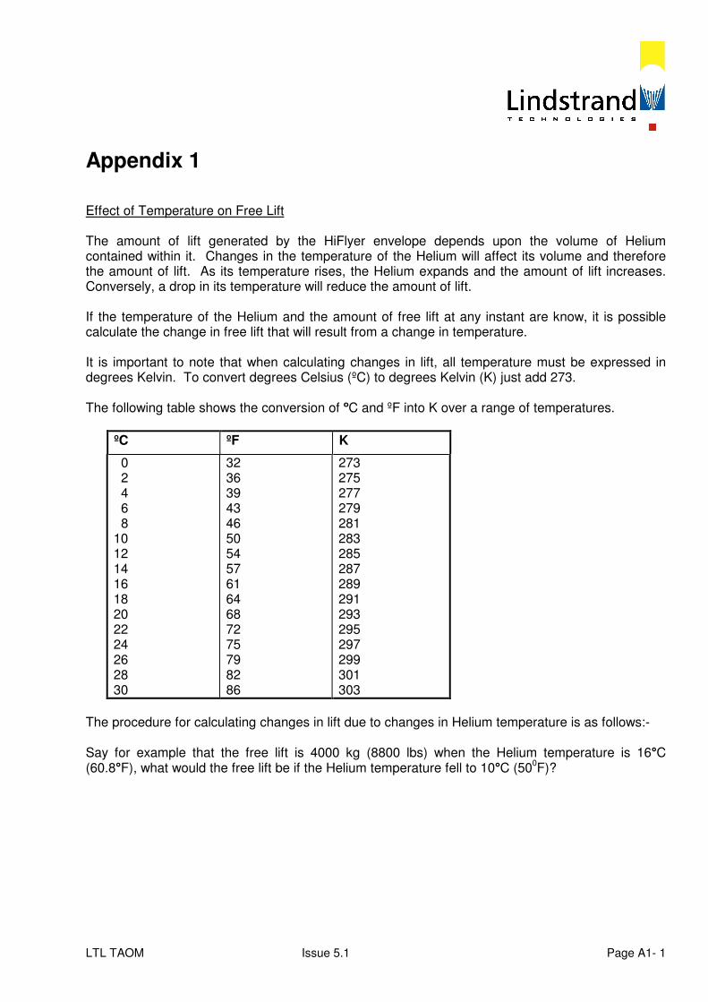
LTL TAOM Issue 5.1 Page A1- 1
Appendix 1 Effect of Temperature on Free Lift The amount of lift generated by the HiFlyer envelope depends upon the volume of Helium contained within it. Changes in the temperature of the Helium will affect its volume and therefore the amount of lift. As its temperature rises, the Helium expands and the amount of lift increases. Conversely, a drop in its temperature will reduce the amount of lift. If the temperature of the Helium and the amount of free lift at any instant are know, it is possible calculate the change in free lift that will result from a change in temperature. It is important to note that when calculating changes in lift, all temperature must be expressed in degrees Kelvin. To convert degrees Celsius (ºC) to degrees Kelvin (K) just add 273. The following table shows the conversion of ºC and ºF into K over a range of temperatures.
ºC ºF K
0 2 4 6 8 10 12 14 16 18 20 22 24 26 28 30
32 36 39 43 46 50 54 57 61 64 68 72 75 79 82 86
273 275 277 279 281 283 285 287 289 291 293 295 297 299 301 303
The procedure for calculating changes in lift due to changes in Helium temperature is as follows:- Say for example that the free lift is 4000 kg (8800 lbs) when the Helium temperature is 16°C (60.8°F), what would the free lift be if the Helium temperature fell to 10°C (50
0F)?
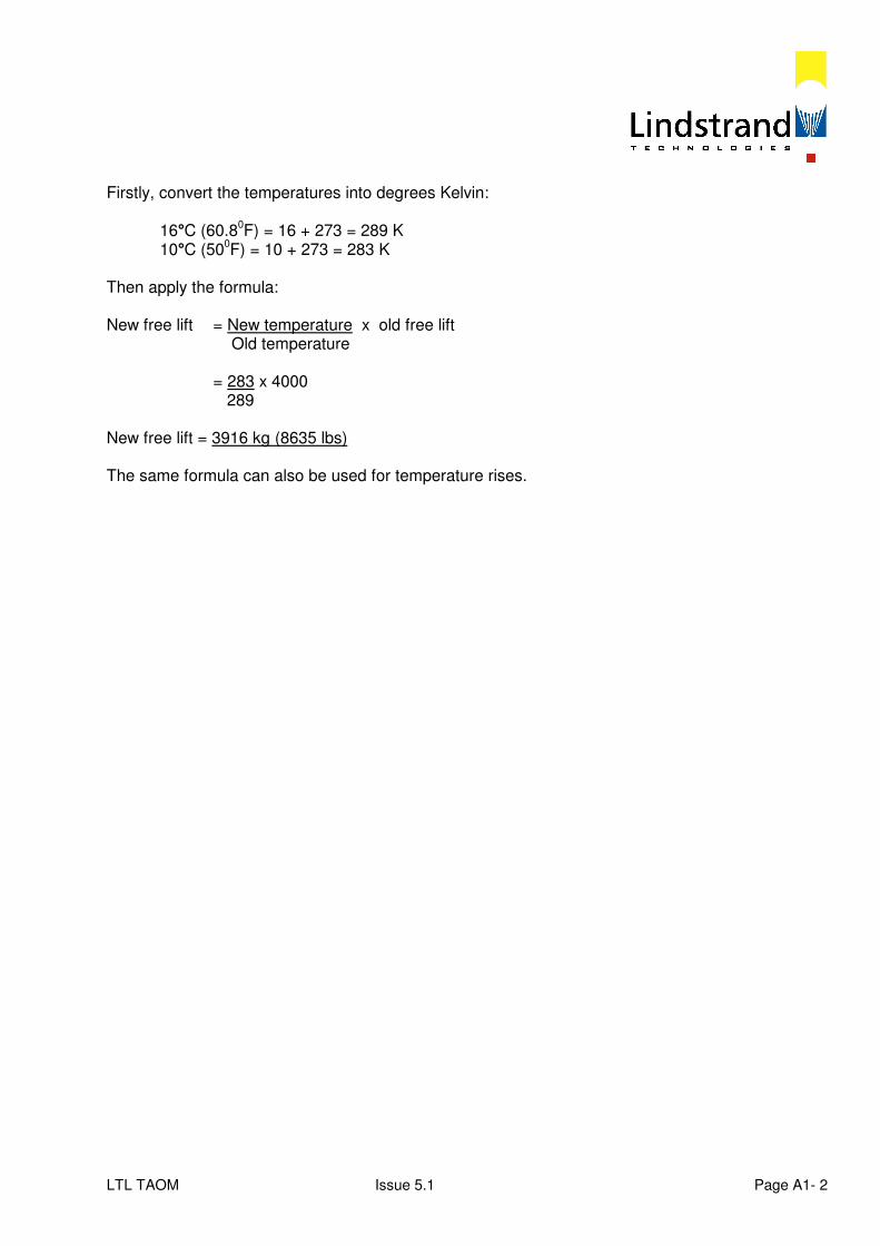
LTL TAOM Issue 5.1 Page A1- 2
Firstly, convert the temperatures into degrees Kelvin: 16°C (60.8
0F) = 16 + 273 = 289 K
10°C (500F) = 10 + 273 = 283 K
Then apply the formula: New free lift = New temperature x old free lift Old temperature = 283 x 4000 289 New free lift = 3916 kg (8635 lbs) The same formula can also be used for temperature rises.
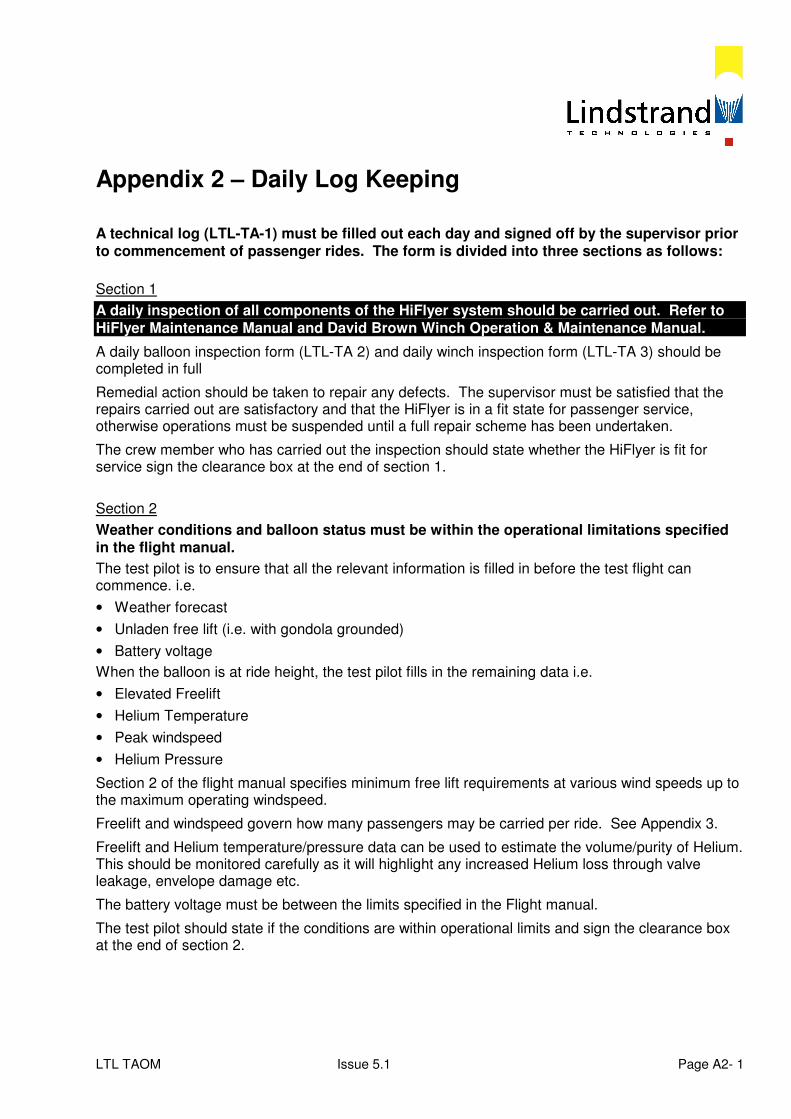
LTL TAOM Issue 5.1 Page A2- 1
Appendix 2 – Daily Log Keeping A technical log (LTL-TA-1) must be filled out each day and signed off by the supervisor prior to commencement of passenger rides. The form is divided into three sections as follows:
Section 1
A daily inspection of all components of the HiFlyer system should be carried out. Refer to HiFlyer Maintenance Manual and David Brown Winch Operation & Maintenance Manual.
A daily balloon inspection form (LTL-TA 2) and daily winch inspection form (LTL-TA 3) should be completed in full
Remedial action should be taken to repair any defects. The supervisor must be satisfied that the repairs carried out are satisfactory and that the HiFlyer is in a fit state for passenger service, otherwise operations must be suspended until a full repair scheme has been undertaken.
The crew member who has carried out the inspection should state whether the HiFlyer is fit for service sign the clearance box at the end of section 1.
Section 2
Weather conditions and balloon status must be within the operational limitations specified in the flight manual.
The test pilot is to ensure that all the relevant information is filled in before the test flight can commence. i.e.
• Weather forecast
• Unladen free lift (i.e. with gondola grounded)
• Battery voltage
When the balloon is at ride height, the test pilot fills in the remaining data i.e.
• Elevated Freelift
• Helium Temperature
• Peak windspeed
• Helium Pressure
Section 2 of the flight manual specifies minimum free lift requirements at various wind speeds up to the maximum operating windspeed.
Freelift and windspeed govern how many passengers may be carried per ride. See Appendix 3.
Freelift and Helium temperature/pressure data can be used to estimate the volume/purity of Helium. This should be monitored carefully as it will highlight any increased Helium loss through valve leakage, envelope damage etc.
The battery voltage must be between the limits specified in the Flight manual.
The test pilot should state if the conditions are within operational limits and sign the clearance box at the end of section 2.

LTL TAOM Issue 5.1 Page A2- 2
The supervisor must sign that he/she is satisfied that the balloon is cleared for operations and that weather conditions and balloon status are within operational limits before passenger rides are allowed to commence.
Section 3
Provides data for calculation of helium usage and information for maintenance schedule of winch.
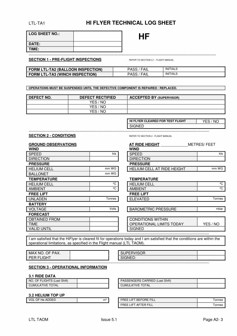
LTL TAOM Issue 5.1 Page A2- 3
LTL-TA1 HI FLYER TECHNICAL LOG SHEET
LOG SHEET NO.: HF
DATE: TIME:
--------------------------------------------------------------------------------------------------------------------------------------- SECTION 1 - PRE-FLIGHT INSPECTIONS REFER TO SECTION 3.1 - FLIGHT MANUAL
FORM LTL-TA2 (BALLOON INSPECTION) PASS / FAIL INITIALS
FORM LTL-TA3 (WINCH INSPECTION) PASS / FAIL INITIALS
OPERATIONS MUST BE SUSPENDED UNTIL THE DEFECTIVE COMPONENT IS REPAIRED / REPLACED.
DEFECT NO. DEFECT RECTIFIED ACCEPTED BY (SUPERVISOR)
YES / NO
YES / NO
YES / NO
HI FLYER CLEARED FOR TEST FLIGHT YES / NO
SIGNED
------------------------------------------------------------------------------------------------------------------------------------------------- SECTION 2 - CONDITIONS REFER TO SECTION 2 - FLIGHT MANUAL GROUND OBSERVATIONS AT RIDE HEIGHT _____________METRES/ FEET
WIND WIND
SPEED kts SPEED kts
DIRECTION DIRECTION
PRESSURE PRESSURE
HELIUM CELL mm WG HELIUM CELL AT RIDE HEIGHT mm WG
BALLONET mm WG
TEMPERATURE TEMPERATURE
HELIUM CELL ºC HELIUM CELL ºC
AMBIENT ºC AMBIENT ºC
FREE LIFT FREE LIFT
UNLADEN Tonnes ELEVATED Tonnes
BATTERY
VOLTAGE Volts BAROMETRIC PRESSURE mbar
FORECAST
OBTAINED FROM CONDITIONS WITHIN
TIME OPERATIONAL LIMITS TODAY YES / NO
VALID UNTIL SIGNED
-------------------------------------------------------------------------------------------------------------------------------------------------
I am satisfied that the HiFlyer is cleared fit for operations today and I am satisfied that the conditions are within the operational limitations, as specified in the Flight manual (LTL TAOM).
MAX NO. OF PAX. SUPERVISOR
PER FLIGHT SIGNED:
------------------------------------------------------------------------------------------------------------------------------------------------- SECTION 3 - OPERATIONAL INFORMATION 3.1 RIDE DATA NO. OF FLIGHTS (Last Shift) PASSENGERS CARRIED (Last Shift) CUMULATIVE TOTAL CUMULATIVE TOTAL
3.2 HELIUM TOP UP VOL OF He ADDED m³ FREE LIFT BEFORE FILL Tonnes
FREE LIFT AFTER FILL Tonnes
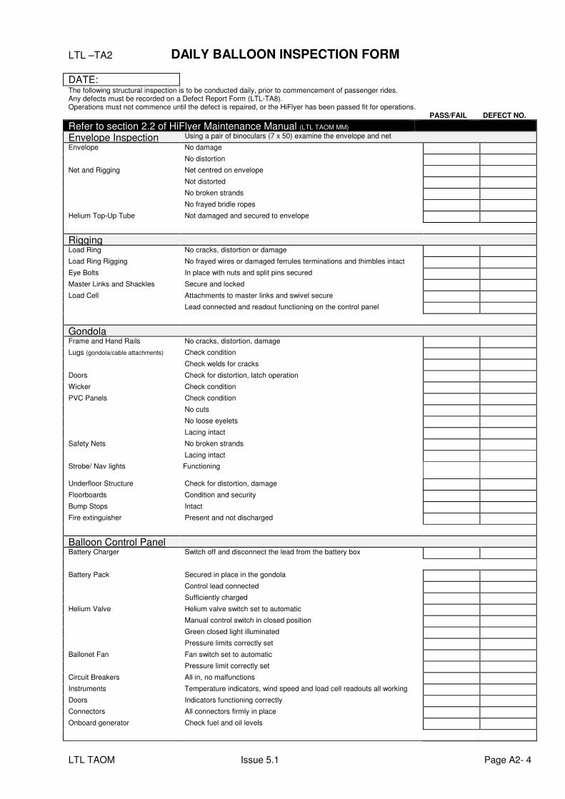
LTL TAOM Issue 5.1 Page A2- 4
LTL –TA2 DAILY BALLOON INSPECTION FORM
DATE: The following structural inspection is to be conducted daily, prior to commencement of passenger rides. Any defects must be recorded on a Defect Report Form (LTL-TA8). Operations must not commence until the defect is repaired, or the HiFlyer has been passed fit for operations. PASS/FAIL DEFECT NO.
Refer to section 2.2 of HiFlyer Maintenance Manual (LTL TAOM MM)
Envelope Inspection Using a pair of binoculars (7 x 50) examine the envelope and net
Envelope No damage
No distortion
Net and Rigging Net centred on envelope
Not distorted
No broken strands
No frayed bridle ropes
Helium Top-Up Tube
Not damaged and secured to envelope
Rigging
Load Ring No cracks, distortion or damage
Load Ring Rigging No frayed wires or damaged ferrules terminations and thimbles intact
Eye Bolts In place with nuts and split pins secured
Master Links and Shackles Secure and locked
Load Cell Attachments to master links and swivel secure
Lead connected and readout functioning on the control panel
Gondola
Frame and Hand Rails No cracks, distortion, damage
Lugs (gondola/cable attachments) Check condition
Check welds for cracks
Doors Check for distortion, latch operation
Wicker Check condition
PVC Panels Check condition
No cuts
No loose eyelets
Lacing intact
Safety Nets No broken strands
Lacing intact
Strobe/ Nav lights Functioning
Underfloor Structure Check for distortion, damage
Floorboards Condition and security
Bump Stops
Intact
Fire extinguisher Present and not discharged
Balloon Control Panel
Battery Charger Switch off and disconnect the lead from the battery box
Battery Pack Secured in place in the gondola
Control lead connected
Sufficiently charged
Helium Valve Helium valve switch set to automatic
Manual control switch in closed position
Green closed light illuminated
Pressure limits correctly set
Ballonet Fan Fan switch set to automatic
Pressure limit correctly set
Circuit Breakers All in, no malfunctions
Instruments Temperature indicators, wind speed and load cell readouts all working
Doors Indicators functioning correctly
Connectors All connectors firmly in place
Onboard generator Check fuel and oil levels
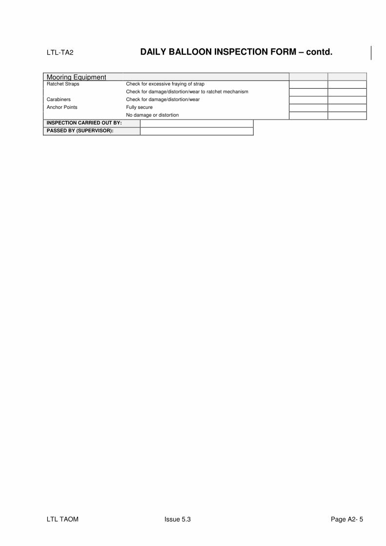
LTL TAOM Issue 5.3 Page A2- 5
LTL-TA2 DAILY BALLOON INSPECTION FORM – contd.
Mooring Equipment
Ratchet Straps Check for excessive fraying of strap
Check for damage/distortion/wear to ratchet mechanism
Carabiners Check for damage/distortion/wear
Anchor Points Fully secure
No damage or distortion
INSPECTION CARRIED OUT BY:
PASSED BY (SUPERVISOR):
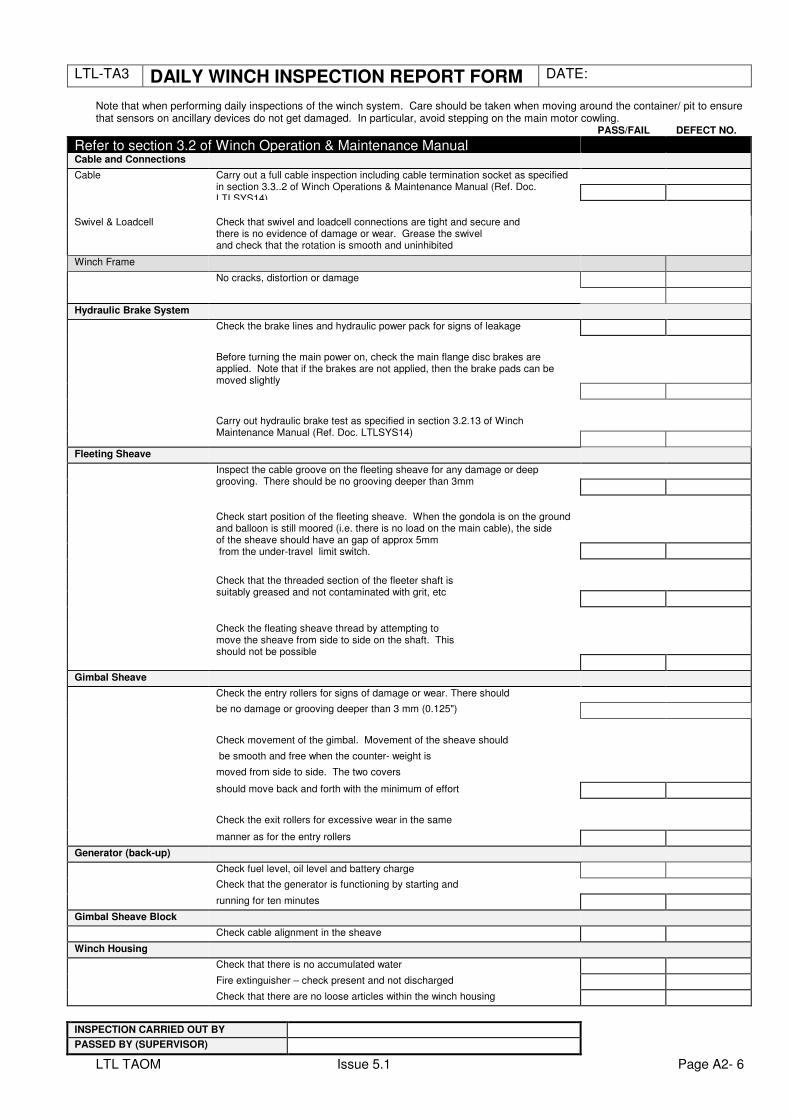
LTL TAOM Issue 5.1 Page A2- 6
LTL-TA3 DAILY WINCH INSPECTION REPORT FORM DATE: Note that when performing daily inspections of the winch system. Care should be taken when moving around the container/ pit to ensure that sensors on ancillary devices do not get damaged. In particular, avoid stepping on the main motor cowling. PASS/FAIL DEFECT NO.
Refer to section 3.2 of Winch Operation & Maintenance Manual
Cable and Connections
Cable Carry out a full cable inspection including cable termination socket as specified in section 3.3..2 of Winch Operations & Maintenance Manual (Ref. Doc. LTLSYS14)
Swivel & Loadcell Check that swivel and loadcell connections are tight and secure and there is no evidence of damage or wear. Grease the swivel and check that the rotation is smooth and uninhibited
Winch Frame
No cracks, distortion or damage
Hydraulic Brake System
Check the brake lines and hydraulic power pack for signs of leakage
Before turning the main power on, check the main flange disc brakes are applied. Note that if the brakes are not applied, then the brake pads can be moved slightly
Carry out hydraulic brake test as specified in section 3.2.13 of Winch Maintenance Manual (Ref. Doc. LTLSYS14)
Fleeting Sheave
Inspect the cable groove on the fleeting sheave for any damage or deep grooving. There should be no grooving deeper than 3mm
Check start position of the fleeting sheave. When the gondola is on the ground and balloon is still moored (i.e. there is no load on the main cable), the side of the sheave should have an gap of approx 5mm from the under-travel limit switch.
Check that the threaded section of the fleeter shaft is suitably greased and not contaminated with grit, etc
Check the fleating sheave thread by attempting to move the sheave from side to side on the shaft. This should not be possible
Gimbal Sheave
Check the entry rollers for signs of damage or wear. There should
be no damage or grooving deeper than 3 mm (0.125")
Check movement of the gimbal. Movement of the sheave should
be smooth and free when the counter- weight is
moved from side to side. The two covers
should move back and forth with the minimum of effort
Check the exit rollers for excessive wear in the same
manner as for the entry rollers
Generator (back-up)
Check fuel level, oil level and battery charge
Check that the generator is functioning by starting and
running for ten minutes
Gimbal Sheave Block
Check cable alignment in the sheave
Winch Housing
Check that there is no accumulated water
Fire extinguisher – check present and not discharged
Check that there are no loose articles within the winch housing
INSPECTION CARRIED OUT BY
PASSED BY (SUPERVISOR)
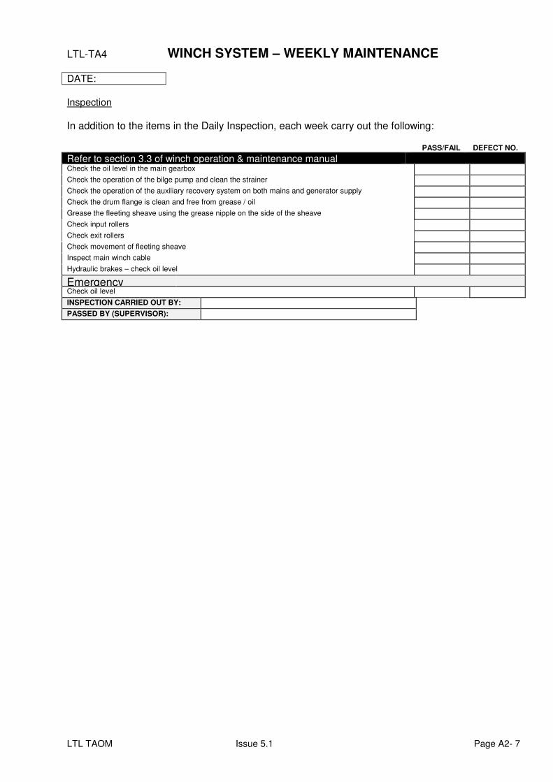
LTL TAOM Issue 5.1 Page A2- 7
LTL-TA4 WINCH SYSTEM – WEEKLY MAINTENANCE DATE:
Inspection
In addition to the items in the Daily Inspection, each week carry out the following: PASS/FAIL DEFECT NO.
Refer to section 3.3 of winch operation & maintenance manual
Check the oil level in the main gearbox
Check the operation of the bilge pump and clean the strainer
Check the operation of the auxiliary recovery system on both mains and generator supply
Check the drum flange is clean and free from grease / oil
Grease the fleeting sheave using the grease nipple on the side of the sheave
Check input rollers
Check exit rollers
Check movement of fleeting sheave
Inspect main winch cable
Hydraulic brakes – check oil level
Emergency
Check oil level
INSPECTION CARRIED OUT BY:
PASSED BY (SUPERVISOR):
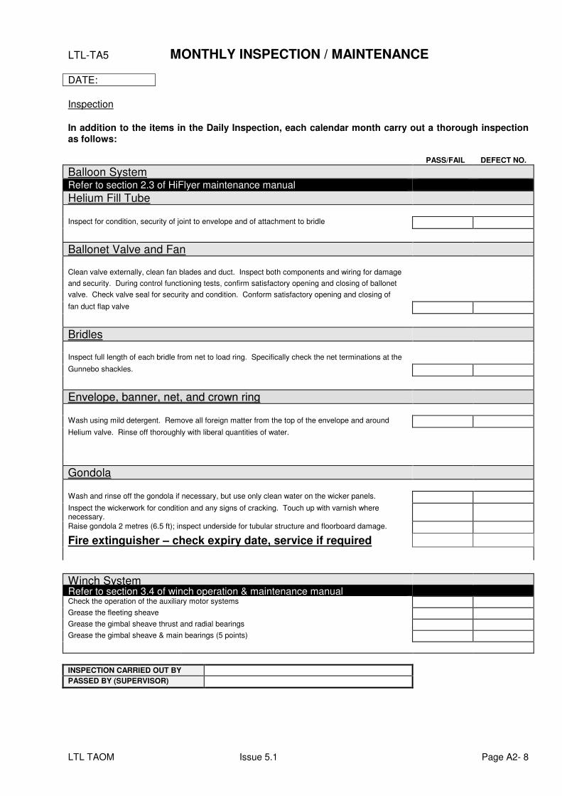
LTL TAOM Issue 5.1 Page A2- 8
LTL-TA5 MONTHLY INSPECTION / MAINTENANCE DATE:
Inspection
In addition to the items in the Daily Inspection, each calendar month carry out a thorough inspection as follows: PASS/FAIL DEFECT NO.
Balloon System
Refer to section 2.3 of HiFlyer maintenance manual
Helium Fill Tube
Inspect for condition, security of joint to envelope and of attachment to bridle
Ballonet Valve and Fan
Clean valve externally, clean fan blades and duct. Inspect both components and wiring for damage
and security. During control functioning tests, confirm satisfactory opening and closing of ballonet
valve. Check valve seal for security and condition. Conform satisfactory opening and closing of
fan duct flap valve
Bridles
Inspect full length of each bridle from net to load ring. Specifically check the net terminations at the
Gunnebo shackles.
EEnnvveellooppee,, bbaannnneerr,, nneett,, aanndd ccrroowwnn rriinngg
Wash using mild detergent. Remove all foreign matter from the top of the envelope and around
Helium valve. Rinse off thoroughly with liberal quantities of water.
Gondola
Wash and rinse off the gondola if necessary, but use only clean water on the wicker panels.
Inspect the wickerwork for condition and any signs of cracking. Touch up with varnish where necessary.
Raise gondola 2 metres (6.5 ft); inspect underside for tubular structure and floorboard damage.
Fire extinguisher – check expiry date, service if required
Winch System
Refer to section 3.4 of winch operation & maintenance manual
Check the operation of the auxiliary motor systems
Grease the fleeting sheave
Grease the gimbal sheave thrust and radial bearings
Grease the gimbal sheave & main bearings (5 points)
INSPECTION CARRIED OUT BY
PASSED BY (SUPERVISOR)
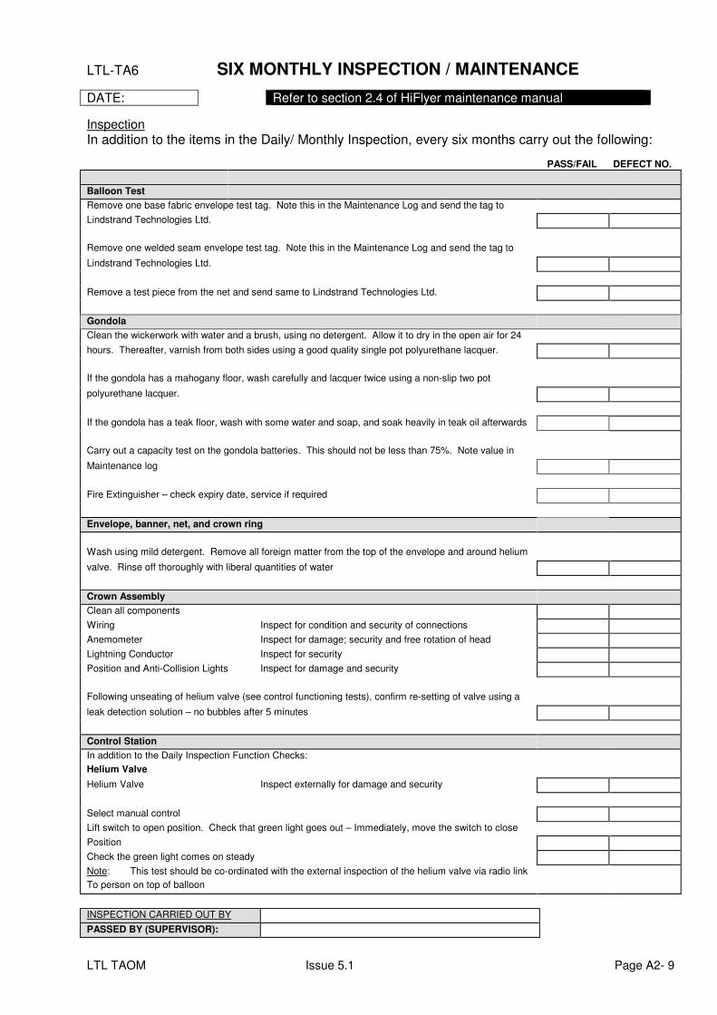
LTL TAOM Issue 5.1 Page A2- 9
LTL-TA6 SIX MONTHLY INSPECTION / MAINTENANCE
DATE: Refer to section 2.4 of HiFlyer maintenance manual
Inspection
In addition to the items in the Daily/ Monthly Inspection, every six months carry out the following: PASS/FAIL DEFECT NO.
Balloon Test
Remove one base fabric envelope test tag. Note this in the Maintenance Log and send the tag to
Lindstrand Technologies Ltd.
Remove one welded seam envelope test tag. Note this in the Maintenance Log and send the tag to
Lindstrand Technologies Ltd.
Remove a test piece from the net and send same to Lindstrand Technologies Ltd.
Gondola
Clean the wickerwork with water and a brush, using no detergent. Allow it to dry in the open air for 24
hours. Thereafter, varnish from both sides using a good quality single pot polyurethane lacquer.
If the gondola has a mahogany floor, wash carefully and lacquer twice using a non-slip two pot
polyurethane lacquer.
If the gondola has a teak floor, wash with some water and soap, and soak heavily in teak oil afterwards
Carry out a capacity test on the gondola batteries. This should not be less than 75%. Note value in
Maintenance log
Fire Extinguisher – check expiry date, service if required
Envelope, banner, net, and crown ring
Wash using mild detergent. Remove all foreign matter from the top of the envelope and around helium
valve. Rinse off thoroughly with liberal quantities of water
Crown Assembly
Clean all components
Wiring Inspect for condition and security of connections
Anemometer Inspect for damage; security and free rotation of head
Lightning Conductor Inspect for security
Position and Anti-Collision Lights Inspect for damage and security
Following unseating of helium valve (see control functioning tests), confirm re-setting of valve using a
leak detection solution – no bubbles after 5 minutes
Control Station
In addition to the Daily Inspection Function Checks:
Helium Valve
Helium Valve Inspect externally for damage and security
Select manual control
Lift switch to open position. Check that green light goes out – Immediately, move the switch to close
Position
Check the green light comes on steady
Note: This test should be co-ordinated with the external inspection of the helium valve via radio link
To person on top of balloon
INSPECTION CARRIED OUT BY
PASSED BY (SUPERVISOR):
LTL TAOM Issue 5.1 Page A2- 10
LTL-TA7
ANNUAL AIRWORTHINESS INSPECTION FOR HIFLYER Refer to section 2.5 of the HiFlyer maintenance manual and section 3.5 of winch operation & maintenance manual
Inspection: In addition to the items in the daily/monthly and 6 Monthly Inspection, every 12 months the system requires an airworthiness inspection which must be carried out by Lindstrand Technologies Limited authorised personnel only. Following this inspection, an Inspection Report and Certificate of Release to Service document will be provided. HiFlyer Systems operating under the jurisdiction of EASA may only operate with a valid Certificate of Airworthiness.
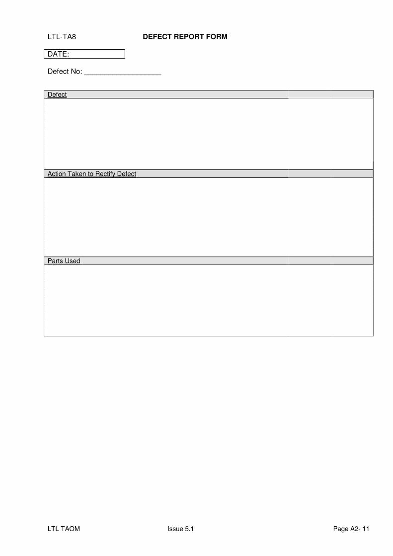
LTL TAOM Issue 5.1 Page A2- 11
LTL-TA8 DEFECT REPORT FORM
DATE:
Defect No: ___________________
Defect
Action Taken to Rectify Defect
Parts Used
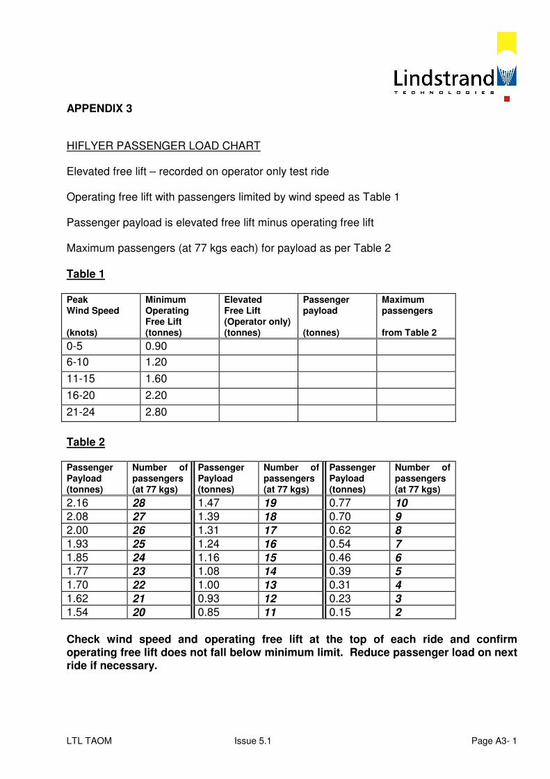
LTL TAOM Issue 5.1 Page A3- 1
APPENDIX 3
HIFLYER PASSENGER LOAD CHART Elevated free lift – recorded on operator only test ride Operating free lift with passengers limited by wind speed as Table 1 Passenger payload is elevated free lift minus operating free lift Maximum passengers (at 77 kgs each) for payload as per Table 2 Table 1 Peak Wind Speed (knots)
Minimum Operating Free Lift (tonnes)
Elevated Free Lift (Operator only) (tonnes)
Passenger payload (tonnes)
Maximum passengers from Table 2
0-5 0.90
6-10 1.20
11-15 1.60
16-20 2.20
21-24 2.80
Table 2 Passenger Payload (tonnes)
Number of passengers (at 77 kgs)
Passenger Payload (tonnes)
Number of passengers (at 77 kgs)
Passenger Payload (tonnes)
Number of passengers (at 77 kgs)
2.16 28 1.47 19 0.77 10
2.08 27 1.39 18 0.70 9
2.00 26 1.31 17 0.62 8
1.93 25 1.24 16 0.54 7
1.85 24 1.16 15 0.46 6
1.77 23 1.08 14 0.39 5
1.70 22 1.00 13 0.31 4
1.62 21 0.93 12 0.23 3
1.54 20 0.85 11 0.15 2
Check wind speed and operating free lift at the top of each ride and confirm operating free lift does not fall below minimum limit. Reduce passenger load on next ride if necessary.
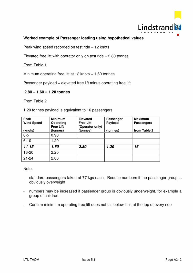
LTL TAOM Issue 5.1 Page A3- 2
Worked example of Passenger loading using hypothetical values Peak wind speed recorded on test ride – 12 knots Elevated free lift with operator only on test ride – 2.80 tonnes From Table 1 Minimum operating free lift at 12 knots = 1.60 tonnes Passenger payload = elevated free lift minus operating free lift 2.80 – 1.60 = 1.20 tonnes From Table 2 1.20 tonnes payload is equivalent to 16 passengers Peak Wind Speed (knots)
Minimum Operating Free Lift (tonnes)
Elevated Free Lift (Operator only) (tonnes)
Passenger Payload (tonnes)
Maximum Passengers from Table 2
0-5 0.90
6-10 1.20
11-15 1.60 2.80 1.20 16
16-20 2.20
21-24 2.80
Note: - standard passengers taken at 77 kgs each. Reduce numbers if the passenger group is
obviously overweight - numbers may be increased if passenger group is obviously underweight, for example a
group of children - Confirm minimum operating free lift does not fall below limit at the top of every ride
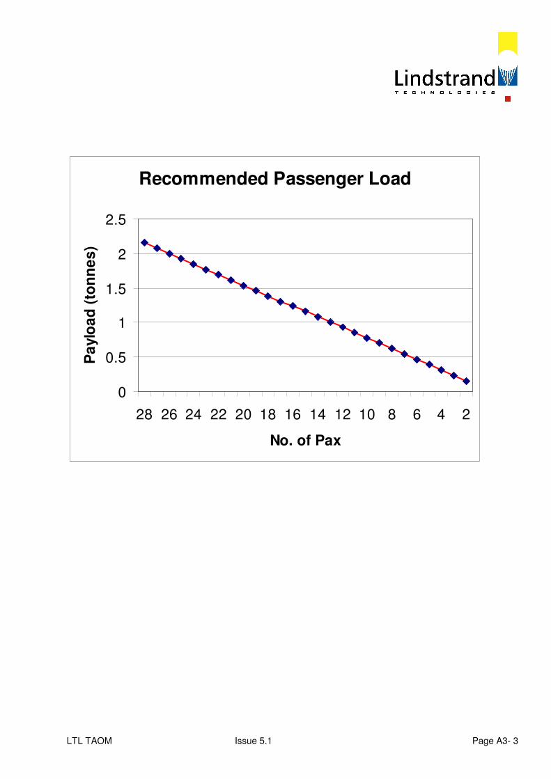
LTL TAOM Issue 5.1 Page A3- 3
Recommended Passenger Load
0
0.5
1
1.5
2
2.5
28 26 24 22 20 18 16 14 12 10 8 6 4 2
No. of Pax
Pa
ylo
ad
(to
nn
es
)
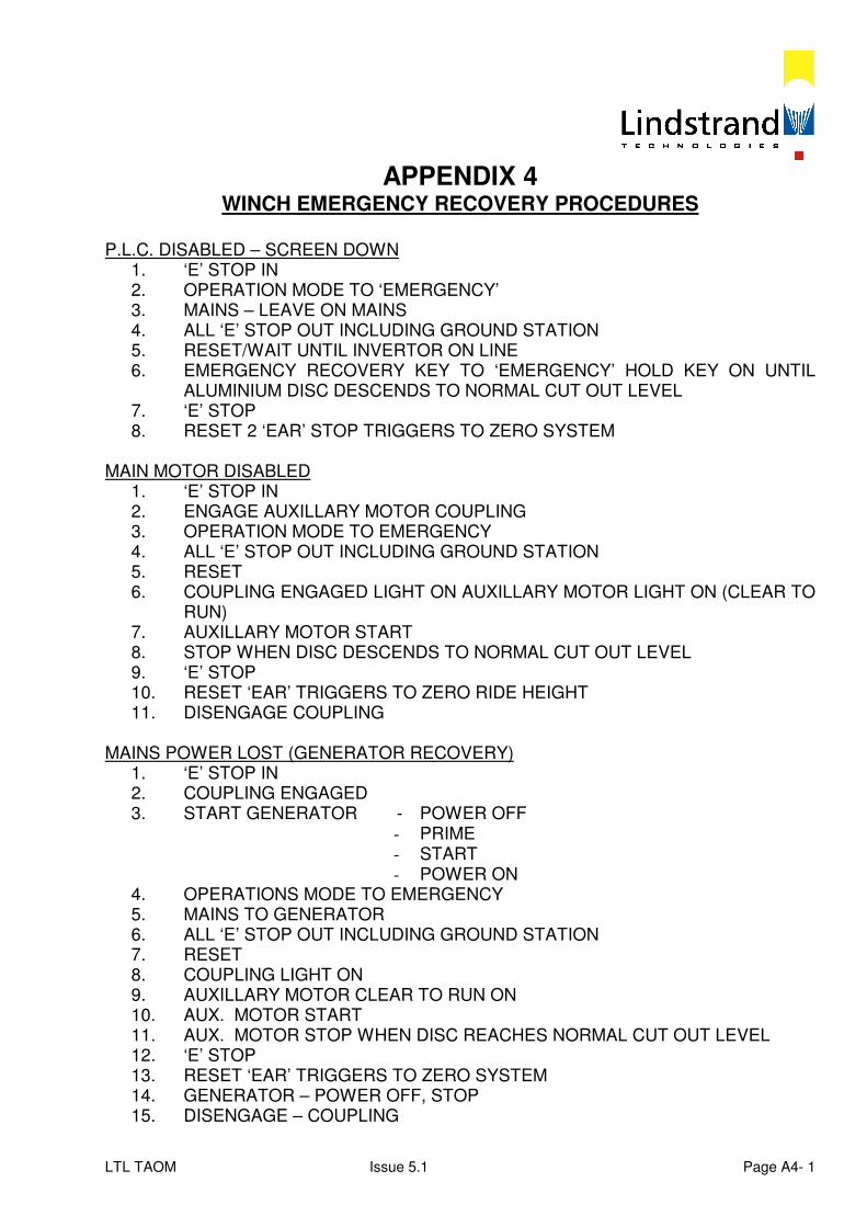
LTL TAOM Issue 5.1 Page A4- 1
APPENDIX 4 WINCH EMERGENCY RECOVERY PROCEDURES
P.L.C. DISABLED – SCREEN DOWN
1. ‘E’ STOP IN 2. OPERATION MODE TO ‘EMERGENCY’ 3. MAINS – LEAVE ON MAINS 4. ALL ‘E’ STOP OUT INCLUDING GROUND STATION 5. RESET/WAIT UNTIL INVERTOR ON LINE 6. EMERGENCY RECOVERY KEY TO ‘EMERGENCY’ HOLD KEY ON UNTIL
ALUMINIUM DISC DESCENDS TO NORMAL CUT OUT LEVEL 7. ‘E’ STOP 8. RESET 2 ‘EAR’ STOP TRIGGERS TO ZERO SYSTEM
MAIN MOTOR DISABLED
1. ‘E’ STOP IN 2. ENGAGE AUXILLARY MOTOR COUPLING 3. OPERATION MODE TO EMERGENCY 4. ALL ‘E’ STOP OUT INCLUDING GROUND STATION 5. RESET 6. COUPLING ENGAGED LIGHT ON AUXILLARY MOTOR LIGHT ON (CLEAR TO
RUN) 7. AUXILLARY MOTOR START 8. STOP WHEN DISC DESCENDS TO NORMAL CUT OUT LEVEL 9. ‘E’ STOP 10. RESET ‘EAR’ TRIGGERS TO ZERO RIDE HEIGHT 11. DISENGAGE COUPLING
MAINS POWER LOST (GENERATOR RECOVERY)
1. ‘E’ STOP IN 2. COUPLING ENGAGED 3. START GENERATOR - POWER OFF
- PRIME - START - POWER ON
4. OPERATIONS MODE TO EMERGENCY 5. MAINS TO GENERATOR 6. ALL ‘E’ STOP OUT INCLUDING GROUND STATION 7. RESET 8. COUPLING LIGHT ON 9. AUXILLARY MOTOR CLEAR TO RUN ON 10. AUX. MOTOR START 11. AUX. MOTOR STOP WHEN DISC REACHES NORMAL CUT OUT LEVEL 12. ‘E’ STOP 13. RESET ‘EAR’ TRIGGERS TO ZERO SYSTEM 14. GENERATOR – POWER OFF, STOP 15. DISENGAGE – COUPLING

LTL TAOM Issue 5.1 Page A5- 1
APPENDIX 5 SPECIAL HELIUM VALVE OPERATIONS
If the envelope Helium gas cell is overfilled, the ballonet can ‘bottom out’ leading to envelope overpressure. See 3.4.11.1. The Helium valve will vent automatically with the alarm sounding at 38 mm WG and the valve opening at 40 mm WG until the pressure falls below 38 mm WG. The excess Helium can also be vented manually by the Helium valve. See 1.2.4.3.4 Do not operate the valve when the balloon is elevated Helium Overfill Indications:
- low ballonet - high freelift - high Helium temperature - high Helium pressure
Before venting Measure ballonet height and record (with balloon in low moored position) Unmoor balloon in calm conditions Connect battery charger to maintain power Record unladen freelift, temperatures and pressures Turn panel key to ‘UNLOCK’ Ballonet fan switch to ‘AUTO’ Manual Helium Valve Operation OBSERVER TO COUNTDOWN ‘OPEN’ TIME AND MONITOR FREELIFT OPERATOR TO CONTROL HELIUM VALVE SWITCHES PRESS TO TEST HELIUM VALVE INDICATOR LIGHTS L.H. HELIUM SWITCH UP TO ‘MANUAL’ R.H. HELIUM SWITCH UP TO ‘OPEN’ RED INDICATOR LIGHT ‘ON’ COUNTDOWN – 4 SECONDS
LTL TAOM Issue 5.1 Page A5- 2
R.H. HELIUM SWITCH DOWN TO ‘CLOSE’ RED INDICATOR ‘OFF’ AFTER 4 SECONDS TRAVEL TIME*
L.H. HELIUM SWITCH TO ‘AUTO’ RECORD OPEN TIME (INDICATOR ‘ON’ TO ‘OFF’) IN SECONDS RECORD NEW (REDUCED) FREELIFT WAIT FOR FAN TO FILL BALLONET REPEAT VENTING PROCEDURE UNTIL TARGET FREELIFT ACHIEVED LOW MOOR BALLOON MEASURE (INCREASED) BALLONET HEIGHT AND RECORD * EMERGENCY VALVE CLOSURE IF VALVE DOES NOT CLOSE: RED INDICATOR REMAINS ‘ON’ ARM EMERGENCY BOX ON TOP OF CONTROL BOX SWITCH ARMING SWITCH UP TO ‘ON’ PUSH RED CLOSE BUTTON FOR A MAXIMUM OF FIFTEEN SECONDS This bypasses the control box systems CONFIRM RED VALVE OPEN INDICATOR ‘OFF’
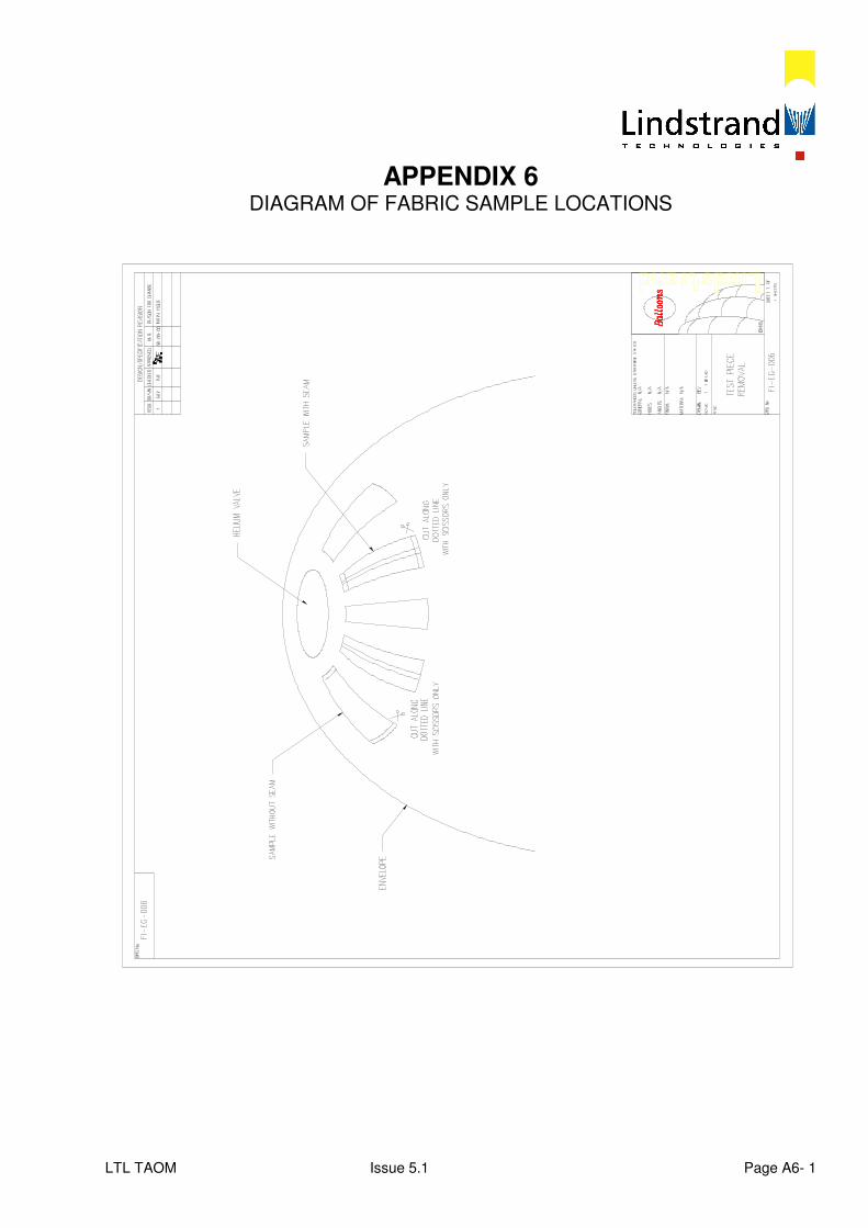
LTL TAOM Issue 5.1 Page A6- 1
APPENDIX 6 DIAGRAM OF FABRIC SAMPLE LOCATIONS
LTL TAOM Issue 5.1 Page A7- 1
APPENDIX 7 MASTER MINIMUM EQUIPMENT LIST
Purpose The document identifies the manufacturers’ recommendation of the minimum equipment that must be serviceable in order that the overall system safety is not degraded. Applicability This document applies to all installations of the HiFlyer System which come under the administration of the National Airworthiness Authority (NAA) in they country of location. It is also recommended for use on all HiFlyer Systems. Serviceable Equipment All component and sub-systems, including all equipment for monitoring and mooring the HiFlyer System, must be serviceable at all times, with the following exceptions:
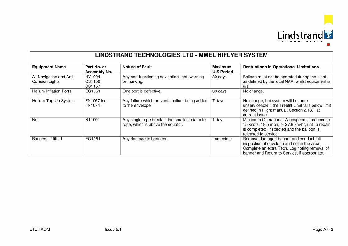
LTL TAOM Issue 5.1 Page A7- 2
LINDSTRAND TECHNOLOGIES LTD - MMEL HIFLYER SYSTEM Equipment Name Part No. or
Assembly No. Nature of Fault Maximum
U/S Period Restrictions in Operational Limitations
All Navigation and Anti-Collision Lights
HV1004 CS1156 CS1157
Any non-functioning navigation light, warning or marking.
30 days Balloon must not be operated during the night, as defined by the local NAA, whilst equipment is u/s.
Helium Inflation Ports
EG1051 One port is defective. 30 days No change.
Helium Top-Up System FN1067 inc. FN1074
Any failure which prevents helium being added to the envelope.
7 days No change, but system will become unserviceable if the Freelift Limit falls below limit defined in Flight manual, Section 2.18.1 at current issue.
Net NT1001 Any single rope break in the smallest diameter rope, which is above the equator.
1 day Maximum Operational Windspeed is reduced to 15 knots, 18.5 mph, or 27.8 km/hr, until a repair is completed, inspected and the balloon is released to service.
Banners, if fitted EG1051 Any damage to banners. Immediate Remove damaged banner and conduct full inspection of envelope and net in the area. Complete an extra Tech. Log noting removal of banner and Return to Service, if appropriate.
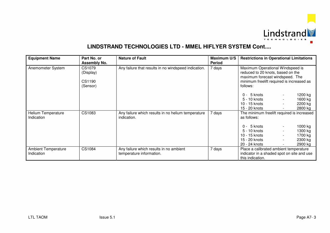
LTL TAOM Issue 5.1 Page A7- 3
LINDSTRAND TECHNOLOGIES LTD - MMEL HIFLYER SYSTEM Cont.... Equipment Name Part No. or
Assembly No. Nature of Fault Maximum U/S
Period Restrictions in Operational Limitations
Anemometer System CS1079 (Display) CS1190 (Sensor)
Any failure that results in no windspeed indication. 7 days Maximum Operational Windspeed is reduced to 20 knots, based on the maximum forecast windspeed. The minimum freelift required is increased as follows: 0 - 5 knots - 1200 kg 5 - 10 knots - 1600 kg 10 - 15 knots - 2200 kg 15 - 20 knots - 2800 kg
Helium Temperature Indication
CS1083 Any failure which results in no helium temperature indication.
7 days The minimum freelift required is increased as follows: 0 - 5 knots - 1000 kg 5 - 10 knots - 1300 kg 10 - 15 knots - 1700 kg 15 - 20 knots - 2300 kg 20 - 24 knots - 2900 kg
Ambient Temperature Indication
CS1084 Any failure which results in no ambient temperature information.
7 days Place a calibrated ambient temperature indicator in a shaded spot on site and use this indication.
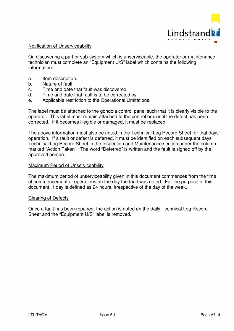
LTL TAOM Issue 5.1 Page A7- 4
Notification of Unserviceability On discovering a part or sub-system which is unserviceable, the operator or maintenance technician must complete an “Equipment U/S” label which contains the following information: a. Item description. b. Nature of fault. c. Time and date that fault was discovered. d. Time and date that fault is to be corrected by. e. Applicable restriction to the Operational Limitations. The label must be attached to the gondola control panel such that it is clearly visible to the operator. This label must remain attached to the control box until the defect has been corrected. If it becomes illegible or damaged, it must be replaced. The above information must also be noted in the Technical Log Record Sheet for that days’ operation. If a fault or defect is deferred, it must be identified on each subsequent days’ Technical Log Record Sheet in the Inspection and Maintenance section under the column marked “Action Taken”. The word “Deferred” is written and the fault is signed off by the approved person. Maximum Period of Unserviceability The maximum period of unserviceability given in this document commences from the time of commencement of operations on the day the fault was noted. For the purpose of this document, 1 day is defined as 24 hours, irrespective of the day of the week. Clearing of Defects Once a fault has been repaired, the action is noted on the daily Technical Log Record Sheet and the “Equipment U/S” label is removed.
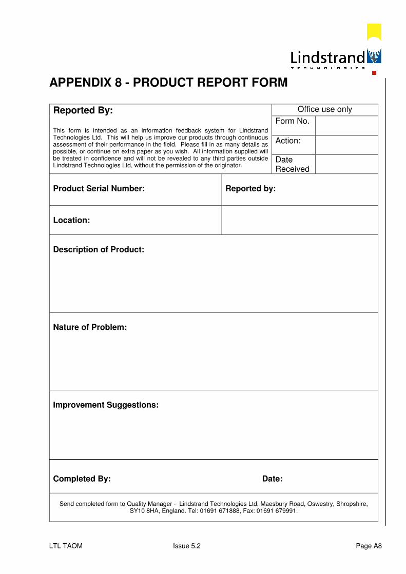
LTL TAOM Issue 5.2 Page A8
APPENDIX 8 - PRODUCT REPORT FORM
Reported By: This form is intended as an information feedback system for Lindstrand Technologies Ltd. This will help us improve our products through continuous assessment of their performance in the field. Please fill in as many details as possible, or continue on extra paper as you wish. All information supplied will be treated in confidence and will not be revealed to any third parties outside Lindstrand Technologies Ltd, without the permission of the originator.
Office use only
Form No.
Action:
Date Received
Product Serial Number:
Reported by:
Location:
Description of Product:
Nature of Problem:
Improvement Suggestions:
Completed By: Date:
Send completed form to Quality Manager - Lindstrand Technologies Ltd, Maesbury Road, Oswestry, Shropshire,
SY10 8HA, England. Tel: 01691 671888, Fax: 01691 679991.
LTL TAOM Issue 5.1 Page S1- 1
SUPPLEMENT 1
GROUND FAN OPERATING INSTRUCTIONS
INTRODUCTION The ground fan is used to pressurise the ballonet and hence maintain the balloon envelope shape when the balloon is moored. It is essential to maintain pressure when the balloon is moored during windy conditions, to prevent the envelope from indenting and reduce wind drag and balloon movement. To speed up pressure recovery in gusty conditions when ballonet air is blown out of the pressure relief valve, the ground fan has a higher performance than the ballonet mounted fan. If the ground fan is operated continuously, there is a danger that the balloon could be over-pressurised and helium vented. To prevent this, the fan is linked into the pressure sensing system displayed in the instrument box which switches the fan on and off to limit pressure. The ground fan is powered by mains or generator A C supply. The ground fan must be disconnected before the balloon is flown or raised to the high mooring position. GROUND FAN INSTALLATION Locate fan on the platform outside the gondola Lead the duct over the top of the gondola and under the mooring ring Couple the duct up to the connection under the ballonet fan. See Figure HF.GF.1 GROUND FAN CONNECTION - Ground fan lead – plug into controller socket located on left hand side of gondola
control box - Fan controller mains lead - plug into mains (or generator) supply socket
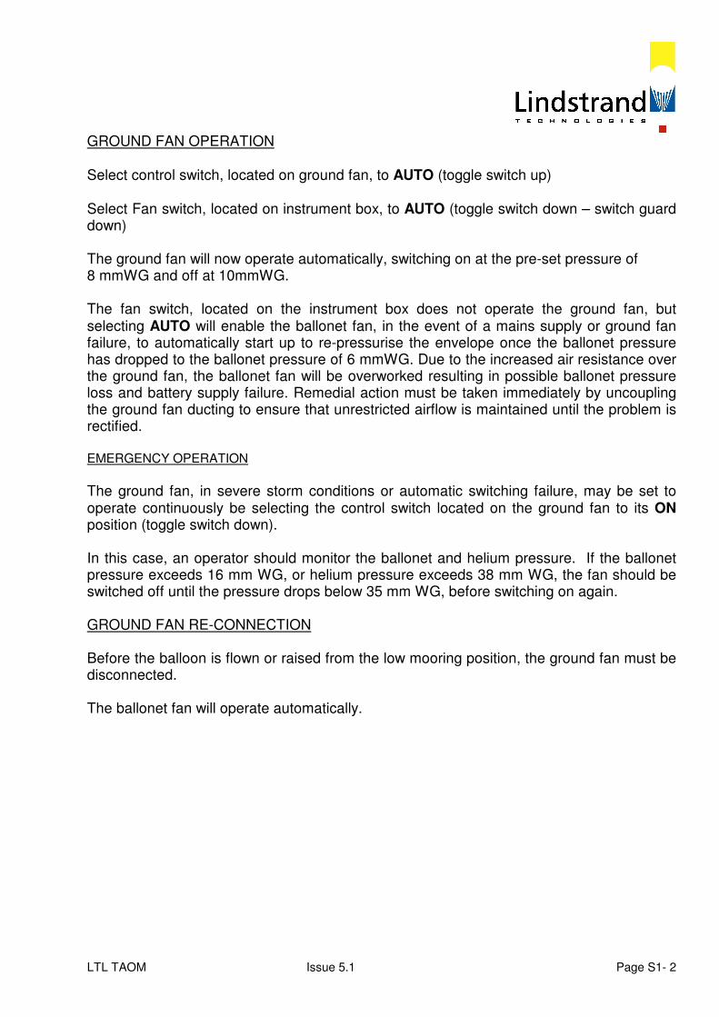
LTL TAOM Issue 5.1 Page S1- 2
GROUND FAN OPERATION Select control switch, located on ground fan, to AUTO (toggle switch up) Select Fan switch, located on instrument box, to AUTO (toggle switch down – switch guard down) The ground fan will now operate automatically, switching on at the pre-set pressure of 8 mmWG and off at 10mmWG. The fan switch, located on the instrument box does not operate the ground fan, but selecting AUTO will enable the ballonet fan, in the event of a mains supply or ground fan failure, to automatically start up to re-pressurise the envelope once the ballonet pressure has dropped to the ballonet pressure of 6 mmWG. Due to the increased air resistance over the ground fan, the ballonet fan will be overworked resulting in possible ballonet pressure loss and battery supply failure. Remedial action must be taken immediately by uncoupling the ground fan ducting to ensure that unrestricted airflow is maintained until the problem is rectified. EMERGENCY OPERATION
The ground fan, in severe storm conditions or automatic switching failure, may be set to operate continuously be selecting the control switch located on the ground fan to its ON position (toggle switch down). In this case, an operator should monitor the ballonet and helium pressure. If the ballonet pressure exceeds 16 mm WG, or helium pressure exceeds 38 mm WG, the fan should be switched off until the pressure drops below 35 mm WG, before switching on again. GROUND FAN RE-CONNECTION Before the balloon is flown or raised from the low mooring position, the ground fan must be disconnected. The ballonet fan will operate automatically.
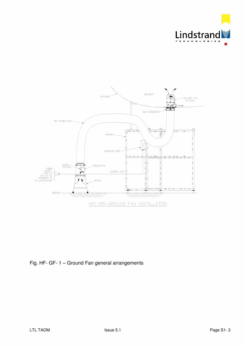
LTL TAOM Issue 5.1 Page S1- 3
Fig. HF- GF- 1 – Ground Fan general arrangements

LTL TAOM Issue 5.1 S2- 1
SUPPLEMENT 2
Internal Illumination Operating Instructions
Generator Version
LTL TAOM Issue 5.1 S2- 2
HIFLYER – INTERNAL ILLUMINATION
Introduction
Internal balloon illumination is provided by suspending high intensity lamps inside the envelope. The electric power is supplied by a self-contained generator mounted on the outside of the gondola. Illumination A cluster of 3 lamps is suspended inside the envelope from the valve plate at the top of the balloon. An access panel in the valve plate is provided for installation and servicing. The lamps hang in a ‘chain’ from the access panel and are centred in the envelope by 3 stability cords. Power is provided via an 8-way connector on HE valve plate. The lamps are protected by a cage, which is bolted to the holder. In case of breakage glass fragments are retained by a protective sock. Lamps 3 lamps 400 W metal Halide Handle lamps gently and do not touch glass Remove lamp system complete before deflating balloon Lamp Operation The lamps are operated from the console mounted above the generator. Power Up Procedure: - Console power lead – connect to blue 240 V socket on generator - Ignition cut-out lead – connect to socket on generator - Lamps power lead – connect to socket on side of console - 240 V – select on generator - Generator ignition switch on - Cut-out switch to ‘Run’ – side of lamp console - Start generator – as Honda Manual and run until warmed up and choke off. - 240 V circuit breaker – switch to ‘on’, red indicator on lamp console illuminated.
LTL TAOM Issue 5.1 S2- 3
Lighting Up Procedure The lamps require a heavy start up current. To reduce the load the lamps are started in sequence as follows: Lamp 1 - Push switch on – illuminated
- Status indicator light should go out during lamp start up and come on steadily after warm up
- Visual check of balloon to confirm lamp lit Lamps 2 & 3 - Repeat procedure after each lamp is fully warmed up. Note: If status indicator does not go out during warm up switch lamp off, wait 10
minutes, and restart. If indicator still does not go out lamp may be faulty.
To Extinguish Lamps
- Illuminated push switch – Push to switch off - 240 V circuit breaker – switch off - Generator cut-out – switch to “KILL” - Fuel valve – shut Lamp Changing - Warning – High Voltage System - Isolate power before commencing any work Access to lamps is from the top of the envelope - Organise Hi Reach truck, or basket crane and safety harness Working from top of balloon - Power off – confirm - Lead to generator – disconnect from access hatch - Access hatch – remove and expose attached suspension wires - Pull up fabric leak stop sleeve through access hole turning it inside out over
suspension wires - Lightly close and knot upper tie cords over wires to throttle Helium leakage - Pull up suspension wires until first lamp unit enters sleeve – Do not pull electric
leads - Close lower tie cord and untie upper to remove lamp - Repeat until faulty lamp is exposed - Remove sock and safety cage from holder - Change lamp – Do not touch glass
LTL TAOM Issue 5.1 S2- 4
- Reverse procedure to replace lamps - Fire up generator and test lamps while access is still available to top of balloon Before Operating the Balloon Again: - Read freelift on loadcell to check Helium loss - Replenish Helium if necessary
Generator A generator is provided to power the lamps. The generator is a portable unit, which can be mounted on the outside of the gondola frame, on the bay to the right of the operator’s station. When the balloon is flown with the generator and lamp console mounted the passenger carrying capacity will be reduced by two passengers due to the additional weight. Generator mounting A Honda Generator EM 2200 is supplied. This unit is mounted on two vertical rails on the outside of the gondola. The rails can be left on the gondola when it is operated without the generator, or can be demounted from the top and bottom M10 studs. Always mount the rails with locking nuts. The back of the generator frame is fitted with 2 hooks at the top and 2 sockets at the bottom. To mount the generator: - Lift the generator and locate hooks over the lower set of bars on the mounting rails - Locate socket fittings between jaws on mounting rails - Push pins through jaws and sockets and lock with ‘R’ clips
Lamp Control Console Mounting The control console mounts on the vertical rails above the generator. The mounting arrangement is identical to the generator.
LTL TAOM Issue 5.1 S2- 5
Generator Operation Caution: The generator produces 240 V.A.C. Do not operate in wet weather or with wet hands Read Honda Manual before operating Fire Suppression If overheating is suspected: - Switch off generator cut-out mounted on side of lamp console - Standby with extinguisher If fire breaks out: - Switch off generator cut-out at first opportunity - Activate fire extinguisher Fire Extinguisher The generator is petrol (gasoline) fuelled so a 2 kg Carbon Dioxide contents extinguisher is provided. The extinguisher is coloured red and mounted on the inner face of the operator’s bay to the right of the control panel. To remove the extinguisher: - Pull cylinder away from panel to release velcro - Lift off hook To operate extinguisher: - Pull out pin - Direct nozzle at base of fire - Squeeze lever Caution nozzle freezes with operation keep hands clear
LTL TAOM Issue 5.1 S2- 6
GB Operating and safety instructions for HIS (T) 250/400 W lamps
1. The lamps are intended for use in open fixtures which fulfil the requirements of IEC
598-1 / EN 60 598 –1. 2. The lamps comply with the requirements of the Sylvania data sheet. The ballasts
used have to comply with the requirements of IEC 923 / EN 60 923 and with the requirements of the Sylvania data sheet.
3. The acceptable variations of supply voltage are indicated on the Sylvania data
sheet. 4. At the end of lamp life, characterized by: - considerable changing of the colour and brightness - periodically going on and off - lamps should be replaced as soon as possible
5. Before replacing a lamp, check for the correct wattage. The lamp bulb must not
show any sign of damage or scratches. 6. Switch off the line before replacing the lamp. The lamp must cool down before
being replaced. Screw the lamp firmly but not forcibly into the socket and switch on the light.
7. During run-up of the lamp, the current is about 40% higher than the nominal
operating current. The light output is nominal after a warm-up time of 2 minutes. 8. In order to reduce individual colour differences and variations of the lamp
performance the mains voltage many not exceed a short-term variation of 5%. When long-term variations (> 3%) are recorded, different connections should be used.
9. Operating of a lamp with broken or punctured glass bulb can cause serious skin
burn and eye inflammation. Arc tube and outer bulbs may unexpectedly rupture due to internal causes or external factors such as system failure or misapplication.
10. Lamps must be disposed of as mercury containing waste according to the local
regulations. Do not break lamp and do not dispose of via household waste.