liquid argon gamma-ray observatory largo a new … · liquid argon gamma-ray observatory largo a...
TRANSCRIPT

LArGO 1
Liquid Argon Gamma-ray ObservatoryLArGO
A new concept of gamma-ray telescope
Eric Charles (SLAC)for
G. A. Caliandro (CIFS/SLAC), E. Bloom (SLAC), R. Cameron (SLAC), T. Shutt (SLAC), D. Akerib (SLAC)

LArGO 2
Main goals
● A new gamma-ray satellite has to be better than Fermi-LAT– Not an easy task, because the LAT is very good!– A ground-braking new technique is necessary
● LArGO focus mainly on the improvement of the angular resolution– Gamma-ray polarization– Better sky mapping
● Maintaining the conversion efficiency, and wide field of view as in the LAT– Better sensitivity
● LArGO can efficiently work as Compton telescope– Thus covering a very broad energy range ~100 KeV – 100 GeV
LArGO 3
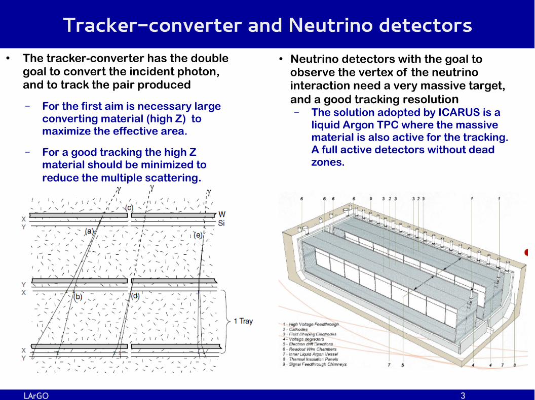
Tracker-converter and Neutrino detectors● The tracker-converter has the double
goal to convert the incident photon, and to track the pair produced
– For the first aim is necessary large converting material (high Z) to maximize the effective area.
– For a good tracking the high Z material should be minimized to reduce the multiple scattering.
● Neutrino detectors with the goal to observe the vertex of the neutrino interaction need a very massive target, and a good tracking resolution– The solution adopted by ICARUS is a
liquid Argon TPC where the massive material is also active for the tracking. A full active detectors without dead zones.

LArGO 4
LArGO
● LArGO design elements– a stack of 32 very thin (6.5 mm)
LAr-TPCs (TPC-layers), – Inter-layer distance 2.5 cm
● the e+e- tracks by 1 GeV photon converted in a TPC-layer are separated at the underlying layer by twice the TPC pitch.
– 1 X0 diluted in 1 m
– Pitch of the drift charge readout plane p = 100 µm
– Spatial resolution 25 µm● Current LAr-TPC have pitch and spatial
resolution of ~1 mm,
– LAr close to triple point (84 K, 70 kPa)● X0 = 20 cm. Minimum multiple scattering

LArGO 5
Performance in pair production regime
Top left: angular resolution of LArGO versus the energy of incident photons converting in the top of a TPC-layer (LArGO top), or at 1 mm from its bottom (LArGO bottom). The red line is the average aperture angle of the converted pair, while the shadowed red area shows its 95% probability distribution.
Right. Profile of the angular resolution versus the depth of the conversion point in a TPC-layer for photons with energy 200 MeV, 500 MeV, and 1 GeV. L = 0 mm is the deepest point of a TPC-layer.

LArGO 6
Compton with LArGO● Two consecutive Compton interactions in
LArGO will happen in different TPC-layers– attenuation length of 1 MeV photons in LAr at
~70kPa is 180 mm– minimum distance d=2.5 cm, spatial
resolution =0.025 mm -> σ δθr negligible
– the angular resolution of LArGO in Compton regime is dominated by its energy resolution
● Energy resolution < 3%– strong anti-correlation between ionization and
scintillation signals
– high photon detection efficiency of SiPMs
● Angular resolution of ~1° @ 1.8 MeV.● Polarization above ~2 MeV
– LArGO is able to track the scattered electron of the first Compton interaction
– stopping power of the electrons in LAr at ~70 kPa is approximately 1.4 MeV/cm.
Crawford, et al., 1987, NIMP A, 256
Aprile, et al., 2007, PhysRev B, 76

LArGO 7
Readout plane: wires vs printed circuits
● ICARUS uses 3 planes of wires (3 mm pitch) to record the drifting electrons– This is a good technique to cover the very
large areas of the ICARUS TPC
● A valid alternative are multi-layer printed strips – This technique was developed in the
ICARUS R&D (P. Cennini, et al., 1994, NIMP A, 346), and for the COIMBRA PET (Solovov, V. et al.,
2002, NIMP A, 477)
Muli-layer printed strips are very suitable ● for covering small
surfaces (like for a TPC-layer of LArGO),
● and to realize strips with very small pitch (~100 µm)

LArGO 8
Multi-layer printed strips applied to LArGO
● The strips are placed at 45° respect the Z-axis of a TPC-layer– The resolution of on-axis
tracks is optimized – The length of the strips is
as short as ~ 1 cm– This configuration is very
useful especially for the signal to noise ratio, and the power consumption

LArGO 9
Signal to Noise
● Signal/Noise– A MIP in LAr produce ~5000 e-/mm. There is no charge amplification in LAr– The main source of noise is from the readout electronics.– ICARUS has ENC ~ 1000 e- per wire (3 mm pitch). S/N~15.
● The ENC is proportional to the total capacitance of the detector– The inter-strip capacitance (Cis) dominates when the pitch is very small
● l, w are the length and the width of the strip, respectively● a,b,c are constants depending by the substrate material
– In ICARUS l/p ~500 – In LArGO, l/p ~100, thanks to the 45° strip configuration– The ENC is reduced by a factor 5 just for the strip configuration in LArGO,
and their shortness
C is=l (a+b w+cp )∝ l
p

LArGO 10
How to reduce the electronic noise
● Low-noise electronics developed for new neutrino and dark matter experiments have reached very low ENC values
ENC < 600 e-
● Other considerations– The electronic of ICARUS is not cold. – It is outside the Dewar. There are very long cables (few meters long) to
connect the readout planes with the electronic (50pF/m)– The total capacitance per wire in ICARUS is ~300 – 400 pF– The inter-strip capacitance estimated for LArGO with the formula in the
previous slide using the constant for a silicon substrate give Cis < 2 pF

LArGO 11
Power consumption and cryogenic ● Number of channels in LArGO is of the same
order of magnitude than the LAT-tracker– Power consumption of the LAT ~160 W
● The power consumption is proportional to the detector capacitance– Hence to the length of the strips– Stript length ratio LAT/LArGO ~ 40– Same ratio for the power consumption– Power consumption of LArGO O(10 W)
Radiator heat lifts
Pierre Jaron, CERN EF.
Collaudin B., Rando N., 2000, Cryo, 40, 797.
● The cryogenic temperature of ~84 K required by the liquid argon in LArGO can be reached even by passive radiators– At 80 K the radiators can
dissipate ~ 1W/m2

LArGO 12
Scintillation light and SiPM
● Primary task of SiPM is to trigger and define the time stamp of an event
● A fiducial volume of the track can be evaluated from the asymmetry of the scintillation light collected by SiPMs– Helpful for the reconstruction– Helpful to discriminate a second
event arrived during the e- drift time of the previous one● Expected ~0.4 particles/300µs
in 50x50 cm2 TPC-layer
Drifting e-
Scintillation light
Fiducial volume
SiPMs
SiPMs
Micro
s trip p
la ne
LArGO 13
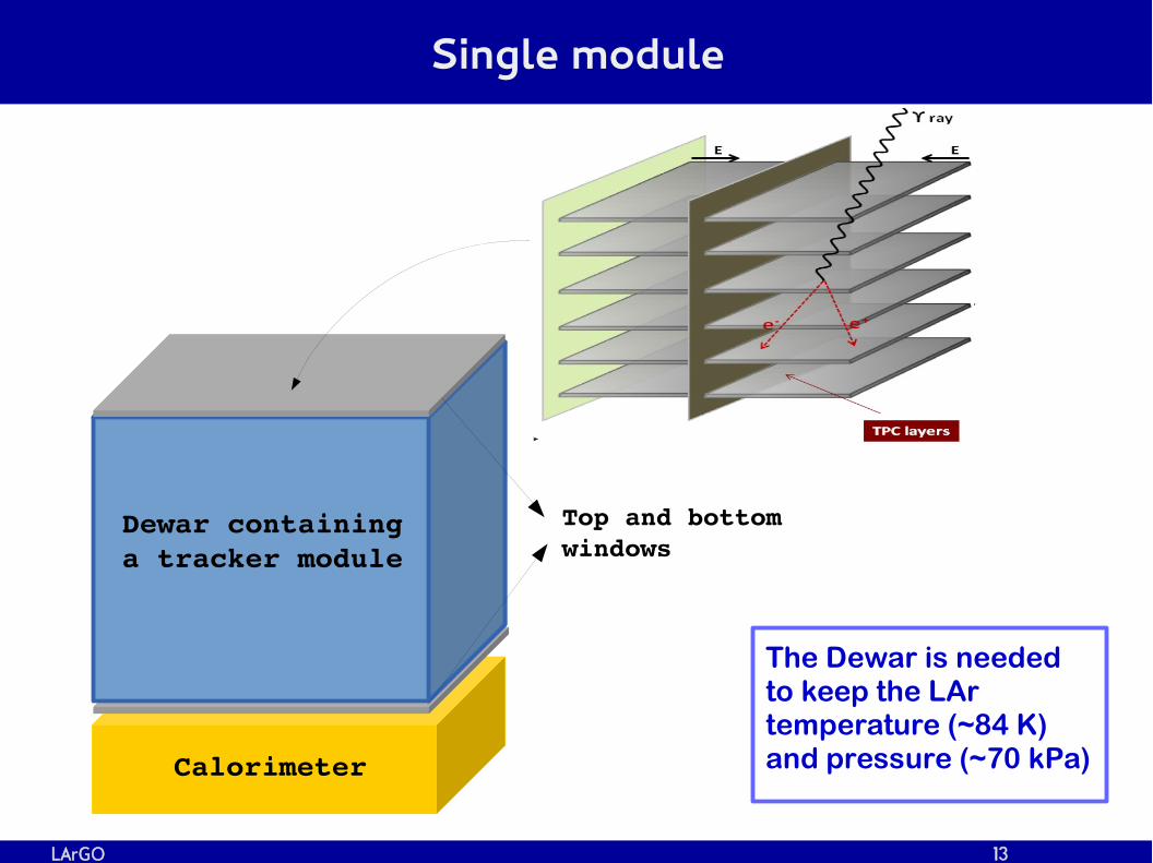
Single module
Dewar containing a tracker module
Calorimeter
Top and bottom windows
The Dewar is needed to keep the LAr temperature (~84 K) and pressure (~70 kPa)

LArGO 14
Satellite design hypothesis
● Height tracker modules with a total geometrical area of 4 m2
● FoV of each module 45° x 30°
● Full FoV >60° x 60°● The 8 modules are
covered by an Anti Coincidence Detector
11
0 c
m
55 cm
22
0 c
m
100 cm
50
cm
Ca
tho
de
Re
ad
ou
t
Dewar containing a tracker module

LArGO 15
Summary
● The challenge of LArGO is to adapt the LAr-TPC technology to the needs of γ-ray astrophysics– The performance of a γ-ray telescope is summarized by 3 parameters:
● Angular resolution, Effective Area (Aeff), Field of view (FoV)
● Main features of LArGO– Unprecedent angular resolution without reducing Aeff and FoV
● LArGO has at 100 MeV approximately the same angular resolution that currently Fermi-LAT has at 1 GeV
– Working in both Compton and pair conversion regimes
– Wide energy range ~100 keV – 100 GeV if coupled with a calorimeter 10 X0 deep
– Polarization measurement in both Compton and pair conversion regime● Polarization energy range ~ 2 MeV – 1 GeV
● LArGO is very promising for a future multipurpose γ-ray telescope

LArGO 16
Backup slides

LArGO 17
Orbits and Rockets
Rockets Diameter (m) Payloads Weight (t) Launch Site Cost
Soyuz-2 (EU-Russia) 3.7 7.8 (LEO)4.5 (GTO)
PlestskKourou (French Guiana)
50M EU?
Arianne 5 (EU) 5.4 16-21 (LEO)7-10 (GTO)
Kourou (French Guiana)
120M EU
Vega (EU) 3.0 1.5 – 2.0 Kourou (French Guiana)
~30M EU
Delta II (US) 2.44 2.7- 6.1 (LEO)0.9 - 2.17 (GTO)1 (open orbit)
Cape Canaveral 36,7M USD (1987)
Delta IV (US) 5.0 8.6 – 25.8 (LEO)3.9 – 10.9 (GTO)
Cape Canaveral/Vanderberg
ATLAS V (US) 3.81 9.8 – 18.8 (LEO)4.7 – 8.9 (GTO)
Cape Canaveral/Vanderberg
Falcon 9 3.7 10.4 – 26.3 (LEO)4.5 – 15.0 (GTO)
Cape Canaveral/Kwajalein
Orbits
Equatorial LEO Langrangian point L2 ISS● Low CR bkg● High down link rate
● Good for Cryogenic● No Earth
albedo/occultation
● Possible human operations after the launch

LArGO 18
LAr TPC working principle and status of the art
● Status of the art: 3ton prototype– 2 grid of wires with a pitch of 2 mm– Spatial resolution in the drift
direction 0.2 mm– Spatial resolution in the readout
plane ~0.6 mm d
d
p
Electronspath
Drift
Ionizing track
Edrift
E2
E1Induction 1
Induction 2
Collection
● Status of the art: ICARUS– 3 grid of wires with a pitch of 3mm– Spatial resolution in the drift
direction 0.7 mm– Spatial resolution in the readout
plane ~1mm– Edrift = 500 V/cm– Electron drift velocity ~ 1.5 mm/µs

LArGO 19
Liquid Argon characteristic features
LAr LXe Si
Cross Section(cm2/g @ 1 MeV)
5.7 x 10⁻² 5.2 x 10⁻² 6.3 x 10⁻²
Density (g/cm3) 1.39 3.06 2.33
Attenuation length (cm @ 1MeV)
12.6 6.3 6.8
Radiation length 14.3 2.77 9.3

LArGO 20
γ-ray polarization
● Pairs are produced preferentially in the plane identified by the linear polarization of the incident photons and its direction – In case of small nuclear recoil ( , eγ +, e- coplanar) the photon
conversion cross section is:
– is the angle between the e+e- plane and the photon's electric field vectorφ
● The gamma-ray polarization can be detected looking for the modulation of the azimuthal angle of the pair planes.φ
σγ(ϕ)=σ0
2 π[1+P λ cos2
(ϕ)]Maximon L. C., Olsen H., 1962, Phys. Rev. 126, 310

LArGO 21
Ingredients for the design of LArGO
● The purpose is to project a tracker for γ-ray telescope which has better performance than Fermi-LAT, and which can work as γ-ray polarimeter at least until photon energies of 1 GeV.– Tracker depth ≥ 1X0
– Tracker full height ~1m
● γ-ray polarizzation– In order for the polarization to be detected, the plane of the converted pair
needs to be identified.– The tracker has to discriminate the two tracks with an angular resolution
lower than their aperture angle
σθ⩽4meE γ
, for E γ⩽1GeV
Aperture angle (W) distribution for E=100 MeV

LArGO 22
Compton regime● When a photon undergoes one or more Compton scatters within the detector,
and then is photoelectrically absorbed, its direction can be reconstructed from the kinematics of the scatterings.
θ
The angular resolution is δθ=√δθE2+δθr
2
uncertainty due to energy measurement
The angular resolution is
δθE∝Δ E /E
δθr∝σ /d due to the error on the position of the scattering points
d
● Tracking the recoil electron of the first Compton interaction– Solve the ambiguity in the sky direction of single
photon– the circle of possible positions on the sky is reduced
to a small arc proportional to the angular resolution (σa) of the electron track.
– the background of gamma-rays from diffuse emission or close sources is reduced, and the sensitivity is improved by a factor
● The measurement of the recoil electron allows the detection of the gamma-ray polarization
√σa/2π
dσCs
d Ω=
12 (re
EE0 )
2
[ EE0
+E0
E−2sin2
θcos2ϕ]

LArGO 23
Compton prototypes ● MEGA
– 32 double sided Si-strip detectors (not interleaved by tungsten foils) surrounded by a pixelated CsI calorimeter
– energy range is 0.4 – 50 MeV– angular resolution of 2°, energy
resolution of 8% @ 2 MeV
θ
● LXeGRIT– liquid Xenon TPC– energy range is 0.3 - 10 MeV– angular resolution of 3°, energy
resolution of 8.8% @ 1 MeV
E. Aprile 1998, NIMP A, 412, 425Bloser P., et al., 2003, NIMPA, 512, 220

LArGO 24
Diffusion
● The electrons drifting toward the anode are affected by diffusion
Transverse diffusion St
S t=√2DLd /vd
● D~4 cm2/s: diffusion coefficient● Vd = 1.5 mm/µs
– For a drift length of 50 cm St~0.5 mm
– St is small compared with the thickness of a TPC-layer (6.5 mm), but larger than the pitch.

LArGO 25
Space resolution in the drift direction
Cennini, P. et al., 1994, NIMP A, 345.

LArGO 26
Particle rate
● lkj
Protons
ElectronsPositrons
Earth albedo neutronsEarth albedo gammas
He