liquid crystals for polarization control in the mwir
TRANSCRIPT

Liquid crystals for polarization control in the MWIR Erika K. Petrak and Thomas G. Baur
Meadowlark Optics, Inc., 5964 Iris Pkwy, Frederick, Co, USA 80530
ABSTRACT
Liquid crystal (LC) technology, a critical component in a diverse range of optics for visible wavelengths, has recently
been adapted into devices for the mid-wave infrared (MWIR). Optics designs, including variable retarders, attenuators,
linear polarization rotators, and tunable filters, have been modified for optimal performance over the range of 3.6 to 5.7
microns.
We constructed these designs using material selected for optimal optical behavior in this wavelength range. Description
and characterization of these chosen component materials is included along with the performance of each device. We
present design challenges, along with future plans and possibilities for MWIR LC technology.
Keywords: Mid-Wave Infrared, Liquid Crystal, Optical Filter, Variable Retarder, Remote Sensing, Electro-Optics,
thermal imaging
1. NOMENCLATURE
Retarder – Polarization manipulation optic used to produce phase changes of incoming light.
Fixed waveplate- A retarder with fixed birefringence, as seen in crystals such as sapphire and magnesium
fluoride, or polymers such as polycarbonate and polyvinyl alcohol. Methods for retardance selection rely most
commonly on physical thickness and optical path length, and mechanical actions.
LC cell – Two substrates laminated together with spacers to form a cavity, which is then filled with birefringent
liquid crystal.
Compensator- Fixed waveplate or liquid crystal variable retarder tuned to a set voltage and combined with fast
axis perpendicular to fast axis of main tunable LCVR in order to achieve a minimum of 0 waves of retardance.
2. INTRODUCTION
LC optics are favored for their non-mechanical polarization control, ease of use, and simple compact design. Standard
optical configurations are frequently remodeled to incorporate LC’s for added capability or to replace much larger, more
complex assemblies.1 LC components for MWIR provide many options and benefits in design flexibility for light-
weight, mobile devices with low power requirements and precise analog tunability.
Commercially available alternatives for MWIR rely heavily on cumbersome fixed waveplate assemblies. These
assemblies require mechanical adjustments for retardance tuning and therefore, do not have the same potential for speed
or on-demand response as electrically controlled mechanisms. LC devices offer random-access variable polarization
control using only a 2.0 kHz AC input signal adjustable from 0V to 10V with user-friendly software interfaces.
This new expansion of nematic LC technology into the MWIR was motivated by the recent availability of high quality
polarizers suitable for such long wavelengths. These polarizers offer high transmission over 3 to 6 microns while
maintaining excellent contrast ratio.2 Coupled with LC variable retarders (LCVR’s), they provide the building blocks of
an array of polarization solutions. These components enable the fabrication of MWIR equivalents for all current visible
wavelength LC optics.
LC devices for MWIR provide stable, highly responsive polarization control for many applications in need of
lightweight, compact devices. Lack of moving parts make LC’s quicker and less susceptible to vibrations and shock,
while also offering precise wavelength selection over their full specified range.1 Applications in remote sensing and
thermal imaging will benefit from the mobility and fine resolution and detail which can be achieved with analog,
electrically-controlled birefringence. Figure 1 shows the LCVR product that is an important building block for the
devices described in the following pages.
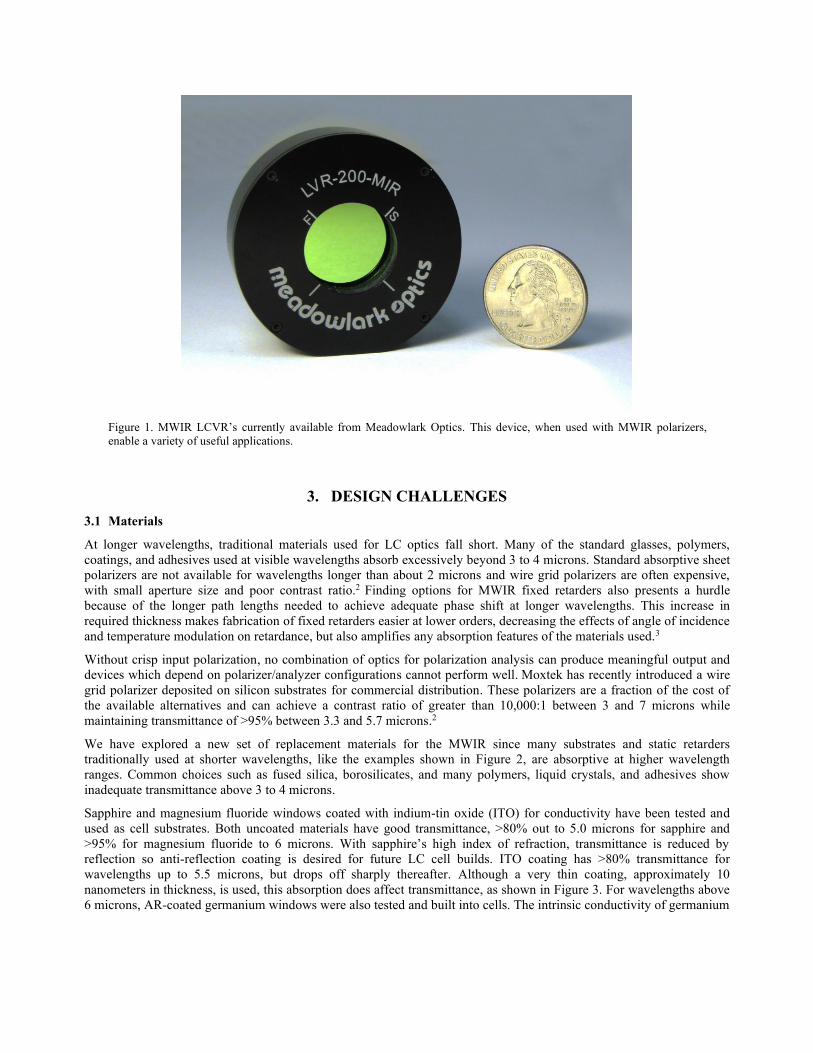
Figure 1. MWIR LCVR’s currently available from Meadowlark Optics. This device, when used with MWIR polarizers,
enable a variety of useful applications.
3. DESIGN CHALLENGES
3.1 Materials
At longer wavelengths, traditional materials used for LC optics fall short. Many of the standard glasses, polymers,
coatings, and adhesives used at visible wavelengths absorb excessively beyond 3 to 4 microns. Standard absorptive sheet
polarizers are not available for wavelengths longer than about 2 microns and wire grid polarizers are often expensive,
with small aperture size and poor contrast ratio.2 Finding options for MWIR fixed retarders also presents a hurdle
because of the longer path lengths needed to achieve adequate phase shift at longer wavelengths. This increase in
required thickness makes fabrication of fixed retarders easier at lower orders, decreasing the effects of angle of incidence
and temperature modulation on retardance, but also amplifies any absorption features of the materials used.3
Without crisp input polarization, no combination of optics for polarization analysis can produce meaningful output and
devices which depend on polarizer/analyzer configurations cannot perform well. Moxtek has recently introduced a wire
grid polarizer deposited on silicon substrates for commercial distribution. These polarizers are a fraction of the cost of
the available alternatives and can achieve a contrast ratio of greater than 10,000:1 between 3 and 7 microns while
maintaining transmittance of >95% between 3.3 and 5.7 microns.2
We have explored a new set of replacement materials for the MWIR since many substrates and static retarders
traditionally used at shorter wavelengths, like the examples shown in Figure 2, are absorptive at higher wavelength
ranges. Common choices such as fused silica, borosilicates, and many polymers, liquid crystals, and adhesives show
inadequate transmittance above 3 to 4 microns.
Sapphire and magnesium fluoride windows coated with indium-tin oxide (ITO) for conductivity have been tested and
used as cell substrates. Both uncoated materials have good transmittance, >80% out to 5.0 microns for sapphire and
>95% for magnesium fluoride to 6 microns. With sapphire’s high index of refraction, transmittance is reduced by
reflection so anti-reflection coating is desired for future LC cell builds. ITO coating has >80% transmittance for
wavelengths up to 5.5 microns, but drops off sharply thereafter. Although a very thin coating, approximately 10
nanometers in thickness, is used, this absorption does affect transmittance, as shown in Figure 3. For wavelengths above
6 microns, AR-coated germanium windows were also tested and built into cells. The intrinsic conductivity of germanium

enables electro-optic cells to be built without additional ITO or other conductive layers, and offers >95% transmittance
out to 11 microns.
Sapphire, magnesium fluoride, and mica are low absorption fixed retarder alternatives which have been tested and used
in the device configurations discussed in later sections. Although the magnitude of birefringence decreases for most
materials with increasing wavelength, these choices all transmit well enough to allow for adequate thicknesses and
optical path lengths.
Figure 2, Absorption commonly seen in materials popularly used in LC devices for visible wavelengths. Fused silica and
borosilicate glass are often used as substrates for LC cells. Dymax OP29 is one example of an optical adhesive widely used
for visible optics assemblies, but unusable in the MWIR because of absorption.
(a)
(b)
Figure 3. (a) Transmittance of 1.15 mm thick ITO-coated sapphire and magnesium fluoride substrates. High index of
refraction for non AR-coated sapphire decreases its overall transmittance. (b) Transmittance of a 10 nanometer thick ITO
coating.

4. FABRICATED DEVICES
LC devices built, tested and discussed below include variable retarders, a variable attenuator, a polarization rotator, and a
tunable optical filter. Testing of these variable retarders, attenuator, and rotator was done on an ellipsometer consisting
of an IR ceramic light source, two Moxtek wire grid on silicon polarizers used as polarizer and analyzer, and a mercury
cadmium telluride (MCT) detector with lock-in amplifier and optical chopper for signal stability. A 1” thick fused silica
block and Andover 3.6 micron long pass filter were inserted into the beam path for wavelength selection. This
combination provides a bandpass full width at half maximum (FWHM) of approximately 50 nm and is centered at 3.65
microns. Spectral scans for all assemblies and filter testing was performed using a Perkins-Elmer Fourier Transform
Infrared Spectrometer (FTIR) with scanning range of 2.3 to 25 microns.
4.1 LCVR
LCVR’s have been fabricated and tested using both germanium and ITO-coated sapphire substrates. Retardance of
single, uncompensated LC cells is voltage controlled between 0.06 waves and 0.54 waves at 4 microns. Combinations of
fixed retarders and cells make virtually any device configuration possible. These cells are electrically tuned using a 2
kHz square wave drive voltage varied from 0 to 10 V. The cells can be combined with a mica, sapphire, or MgF2
compensator to attain 0 waves minimum retardance.
The increasing retardance demand on devices as wavelength increases causes a challenge in achieving sufficient stroke
in LC cells. Retardance (δ) in phase shift depends on birefringence (β) and thickness (t) of a retarder, as well as on the
wavelength at which the phase shift is desired.3
δ = (β x t)/ λ (1)
An LCVR capable of a 0.5 wave retardance shift at 4 microns requires a relatively thick liquid crystal layer. We used E7
liquid crystal for which we measured a birefringence of approximately 0.17 at a wavelength of 4 microns. From
Equation (1) above, this gives a liquid layer thickness of 12 microns. We chose instead to combine a pair of LC cells
with parallel optic axes, each with a 6 micron thick LC layer. This configuration enabled us to achieve greater switching
speed and improved LC alignment. Testing for speed shows our double-cell 0.5 wave LCVR built with germanium
substrates switches at 30 ms when voltage is applied and 84 ms for relaxation. Cells are combined in what is referred to
as a pseudo pi cell configuration which reduces the change in retardance with angle of incidence.1
Germanium substrates, like the ones used in Meadowlark Optics’ current commercially offered MWIR LCVR, have
transmittance beyond 5.7 microns, seen in Figure 4(a), but are opaque at visible wavelengths and therefore hard to build
with and verify quality of LC fill and cell parallelism. ITO-coated sapphire and magnesium fluoride do hold the
advantage of transparency for ease of build but do not have the potential for transmittance beyond 6 and 9 microns,
respectively, as shown in Figure 4(c). Precise alignment or orientation of optic axis perpendicular to the plane of
incidence is important when building with both of these birefringent materials however to avoid any unwanted
retardance.
Barium fluoride and calcium fluoride are also promising substrate candidates for their transmittance ranges. We have yet
to build an LC cell with either material. ITO-coating has been successful on CaF2 windows, but we have not yet tried
ITO-coating BaF2 windows.

(a) (b)
(c) (d)
Figure 4, Transmittance (a) and retardance (b) of double-cell LCVR, built with 0.57 waves maximum retardance at 3.65
microns, using germanium substrates. Transmittance (c) and retardance (d) of a single-cell LCVR built with 0.33 waves
maximum retardance at 3.65 microns, using ITO-coated sapphire substrates.
4.2 VariableAttenuator
The liquid crystal variable attenuator (LCVA) delivers continuous intensity control in real-time. The device built and
discussed here is comprised of a double LC cell stack compensated with a mica retarder for variability between 0.5 waves and 0 waves at 3.65 microns. This LC stack is placed between two crossed MWIR polarizers, shown in Figure 5.
Figure 5. LCVA configuration.
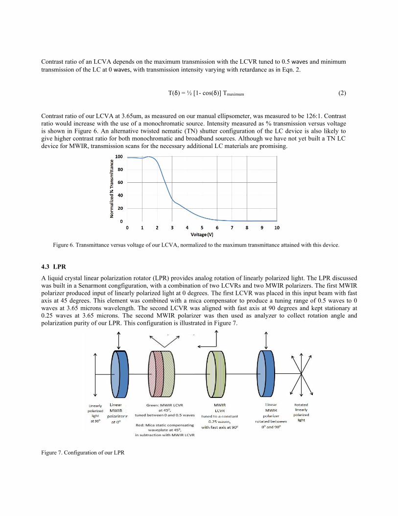
Contrast ratio of an LCVA depends on the maximum transmission with the LCVR tuned to 0.5 waves and minimum
transmission of the LC at 0 waves, with transmission intensity varying with retardance as in Eqn. 2.
T(δ) = ½ [1- cos(δ)] Tmaximum (2)
Contrast ratio of our LCVA at 3.65um, as measured on our manual ellipsometer, was measured to be 126:1. Contrast
ratio would increase with the use of a monochromatic source. Intensity measured as % transmission versus voltage
is shown in Figure 6. An alternative twisted nematic (TN) shutter configuration of the LC device is also likely to
give higher contrast ratio for both monochromatic and broadband sources. Although we have not yet built a TN LC
device for MWIR, transmission scans for the necessary additional LC materials are promising.
Figure 6. Transmittance versus voltage of our LCVA, normalized to the maximum transmittance attained with this device.
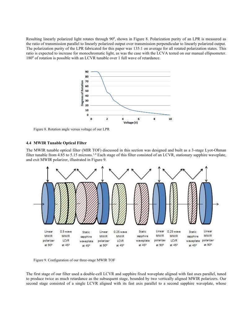
4.3 LPR
A liquid crystal linear polarization rotator (LPR) provides analog rotation of linearly polarized light. The LPR discussed
was built in a Senarmont congfiguration, with a combination of two LCVRs and two MWIR polarizers. The first MWIR
polarizer produced input of linearly polarized light at 0 degrees. The first LCVR was placed in this input beam with fast
axis at 45 degrees. This element was combined with a mica compensator to produce a tuning range of 0.5 waves to 0
waves at 3.65 microns wavelength. The second LCVR was aligned with fast axis at 90 degrees and kept stationary at
0.25 waves at 3.65 microns. The second MWIR polarizer was then used as analyzer to collect rotation angle and
polarization purity of our LPR. This configuration is illustrated in Figure 7.
Figure 7. Configuration of our LPR
Resulting linearly polarized light rotates through 900, shown in Figure 8. Polarization purity of an LPR is measured as
the ratio of transmission parallel to linearly polarized output over transmission perpendicular to linearly polarized output.
The polarization purity of the LPR fabricated for this paper was 135:1 on average for all rotated polarization states. This
ratio is expected to increase for monochromatic light, as was the case with the LCVA tested on our manual ellipsometer.
1800 of rotation is possible with an LCVR tunable over 1 full wave of retardance.
Figure 8. Rotation angle versus voltage of our LPR
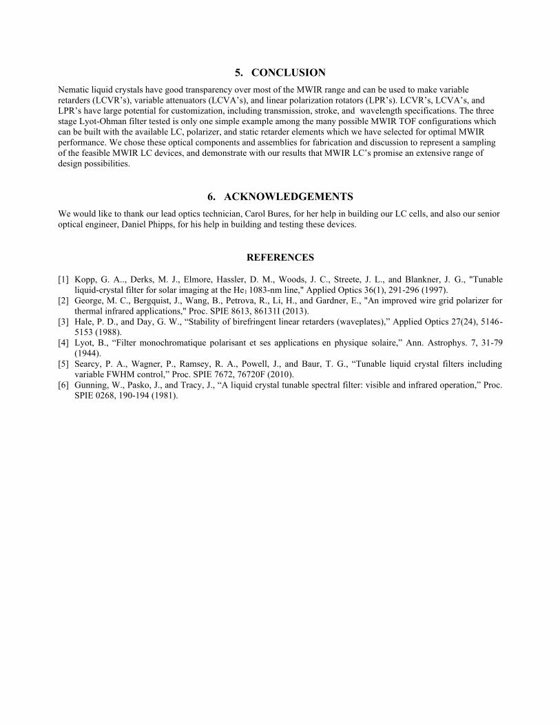
4.4 MWIR Tunable Optical Filter
The MWIR tunable optical filter (MIR TOF) discussed in this section was designed and built as a 3-stage Lyot-Ohman
filter tunable from 4.85 to 5.15 microns.1,4 Each stage of this filter consisted of an LCVR, stationary sapphire waveplate,
and exit MWIR polarizer, illustrated in Figure 9.
Figure 9. Configuration of our three-stage MWIR TOF
The first stage of our filter used a double-cell LCVR and sapphire fixed waveplate aligned with fast axes parallel, tuned
to produce twice as much retardance as the subsequent stage, bounded by two vertically aligned MWIR polarizers. Our
second stage consisted of a single LCVR aligned with its fast axis parallel to a second sapphire waveplate, whose

thickness was half that of the fixed waveplate used in stage 1, and a second vertically aligned polarizer. The third stage
used a single LCVR and a sapphire waveplate of half the thickness of the stage 2 fixed waveplate, and was capped by a
final, vertically aligned MWIR polarizer. These fixed waveplate thickness were chosen from retarders we had on hand
such that subsequent stages would produce destructive interference symmetrically with transmission peaks formed by
stage 1, increasing the free spectral range (FSR) of our filter, as illustrated by Figure 10.
Figure 10. Superposition of transmission peaks produced by stages 1, 2, and 3 of our MWIR TOF, tuned to 4.85 microns.
These three stages combined to produce our MWIR TOF, tunable over 4.85 to 5.15 microns with an average peak
transmission, shown in Figure 11, of 10% and spectral resolution of .33 microns full width of peak at half maximum
(FWHM). Transmittance decrease with wavelength from 4.85 microns to 5.15 microns is due to the absorption profile of
sapphire. Peak transmittance at all wavelengths can be increased by 75% by adding AR coatings on all ten air to sapphire
interfaces in this particular filter design. FSR was measured to be 1.5 microns.
Figure 11. Transmission of the MWIR TOF, tuned to 4.85 microns (red) and 5.15 microns (blue). Peak transmission should
increase by 75% with antireflection coatings on the ten air to sapphire interfaces of this filter.
This design can be modified to optimize filter characteristics. Additional stages will increase FSR. Selecting fixed
waveplates with greater retardances can decrease FWHM, and tuning range can be increased by using LCVR’s with
greater stroke.
With the success of this Lyot-Ohman design, we have confidence that other filter configurations would be easily
adaptable from visible designs.5 Solc and Fabry-Perot style filters and combinations are possible. Fabry-Perot etalons are
especially feasible for MWIR since longer wavelengths could decrease the sensitivity of filter performance to parallelism
of the substrates, a major fabrication challenge for visible wavelength Fabry-Perot filters.6
5. CONCLUSION
Nematic liquid crystals have good transparency over most of the MWIR range and can be used to make variable
retarders (LCVR’s), variable attenuators (LCVA’s), and linear polarization rotators (LPR’s). LCVR’s, LCVA’s, and
LPR’s have large potential for customization, including transmission, stroke, and wavelength specifications. The three
stage Lyot-Ohman filter tested is only one simple example among the many possible MWIR TOF configurations which
can be built with the available LC, polarizer, and static retarder elements which we have selected for optimal MWIR
performance. We chose these optical components and assemblies for fabrication and discussion to represent a sampling
of the feasible MWIR LC devices, and demonstrate with our results that MWIR LC’s promise an extensive range of
design possibilities.
6. ACKNOWLEDGEMENTS
We would like to thank our lead optics technician, Carol Bures, for her help in building our LC cells, and also our senior
optical engineer, Daniel Phipps, for his help in building and testing these devices.
REFERENCES
[1] Kopp, G. A.., Derks, M. J., Elmore, Hassler, D. M., Woods, J. C., Streete, J. L., and Blankner, J. G., "Tunable
liquid-crystal filter for solar imaging at the He1 1083-nm line," Applied Optics 36(1), 291-296 (1997).
[2] George, M. C., Bergquist, J., Wang, B., Petrova, R., Li, H., and Gardner, E., "An improved wire grid polarizer for
thermal infrared applications," Proc. SPIE 8613, 86131I (2013).
[3] Hale, P. D., and Day, G. W., “Stability of birefringent linear retarders (waveplates),” Applied Optics 27(24), 5146-
5153 (1988).
[4] Lyot, B., “Filter monochromatique polarisant et ses applications en physique solaire,” Ann. Astrophys. 7, 31-79
(1944).
[5] Searcy, P. A., Wagner, P., Ramsey, R. A., Powell, J., and Baur, T. G., “Tunable liquid crystal filters including
variable FWHM control,” Proc. SPIE 7672, 76720F (2010).
[6] Gunning, W., Pasko, J., and Tracy, J., “A liquid crystal tunable spectral filter: visible and infrared operation,” Proc.
SPIE 0268, 190-194 (1981).