Logix5000 Control Systems:Connecting PowerFlex …...Logix5000 Control Systems: Connect PowerFlex 525 Drives over an EtherNet/IP Network Catalog Numbers Logix5000 Controllers, PowerFlex
36
Logix5000 Control Systems: Connect PowerFlex 525 Drives over an EtherNet/IP Network Catalog Numbers Logix5000 Controllers, PowerFlex 525 Drives Quick Start
Logix5000 Control Systems Connect PowerFlex 525 Drives over an EtherNetIP NetworkCatalog Numbers Logix5000 Controllers PowerFlex 525 Drives
Quick Start
Important User Information
Solid-state equipment has operational characteristics differing from those of electromechanical equipment Safety Guidelines for the Application Installation and Maintenance of Solid State Controls (publication SGI-11 available from your local Rockwell Automation sales office or online at httpwwwrockwellautomationcomliterature) describes some important differences between solid-state equipment and hard-wired electromechanical devices Because of this difference and also because of the wide variety of uses for solid-state equipment all persons responsible for applying this equipment must satisfy themselves that each intended application of this equipment is acceptable
In no event will Rockwell Automation Inc be responsible or liable for indirect or consequential damages resulting from the use or application of this equipment
The examples and diagrams in this manual are included solely for illustrative purposes Because of the many variables and requirements associated with any particular installation Rockwell Automation Inc cannot assume responsibility or liability for actual use based on the examples and diagrams
No patent liability is assumed by Rockwell Automation Inc with respect to use of information circuits equipment or software described in this manual
Reproduction of the contents of this manual in whole or in part without written permission of Rockwell Automation Inc is prohibited
Throughout this manual when necessary we use notes to make you aware of safety considerations
Allen-Bradley CompactLogix ControlLogix Integrated Architecture Logix5000 PowerFlex Rockwell Software Rockwell Automation RSLogix RSLinx Stratix 6000 Studio 5000 and TechConnect are trademarks of Rockwell Automation Inc
Trademarks not belonging to Rockwell Automation are property of their respective companies
WARNING Identifies information about practices or circumstances that can cause an explosion in a hazardous environment which may lead to personal injury or death property damage or economic loss
ATTENTION Identifies information about practices or circumstances that can lead to personal injury or death property damage or economic loss Attentions help you identify a hazard avoid a hazard and recognize the consequence
SHOCK HAZARD Labels may be on or inside the equipment for example a drive or motor to alert people that dangerous voltage may be present
BURN HAZARD Labels may be on or inside the equipment for example a drive or motor to alert people that surfaces may reach dangerous temperatures
IMPORTANT Identifies information that is critical for successful application and understanding of the product
Table of Contents
PrefaceAbout This Publication 5Before Using This Publication 5Controller and Other Component Quick Starts 7Use Each Chapter 7Where to Start 8How Hardware is Connected 9Required Software 9Parts List 10Additional Resources 10
Chapter 1Prepare the PowerFlex 525 Drive Hardware
Before You Begin 11What You Need 11Follow These Steps 12Mount the Drive 13Install Power Wiring 13Configure the Embedded EtherNetIP Adapter 16Additional Resources 18
Chapter 2Add a PowerFlex 525 Drive to a Controller Project
Before You Begin 19What You Need 19Follow These Steps 20Add the Drive to the Controller Project 21Download the Project and Connect to the Drive 25Edit the Drive Parameters 26Test the PowerFlex 525 Drive Tags 28Additional Resources 30
Index
Rockwell Automation Publication IASIMP-QS036A-EN-P - April 2013 3
Table of Contents
4 Rockwell Automation Publication IASIMP-QS036A-EN-P - April 2013
Preface
About This Publication
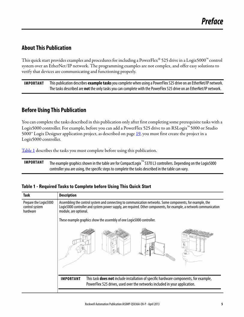
This quick start provides examples and procedures for including a PowerFlexreg 525 drive in a Logix5000trade control system over an EtherNetIP network The programming examples are not complex and offer easy solutions to verify that devices are communicating and functioning properly
Before Using This Publication
You can complete the tasks described in this publication only after first completing some prerequisite tasks with a Logix5000 controller For example before you can add a PowerFlex 525 drive to an RSLogixtrade 5000 or Studio 5000trade Logix Designer application project as described on page 19 you must first create the project in a Logix5000 controller
Table 1 describes the tasks you must complete before using this publication
IMPORTANT This publication describes example tasks you complete when using a PowerFlex 525 drive on an EtherNetIP network The tasks described are not the only tasks you can complete with the PowerFlex 525 drive on an EtherNetIP network
IMPORTANT The example graphics shown in the table are for CompactLogixtrade 5370 L3 controllers Depending on the Logix5000 controller you are using the specific steps to complete the tasks described in the table can vary
Table 1 - Required Tasks to Complete before Using This Quick Start
Task Description
Prepare the Logix5000 control system hardware
Assembling the control system and connecting to communication networks Some components for example the Logix5000 controller and system power supply are required Other components for example a network communication module are optional
These example graphics show the assembly of one Logix5000 controller
2 (Rear)
1 (Front)
IMPORTANT This task does not include installation of specific hardware components for example PowerFlex 525 drives used over the networks included in your application
Rockwell Automation Publication IASIMP-QS036A-EN-P - April 2013 5
Preface
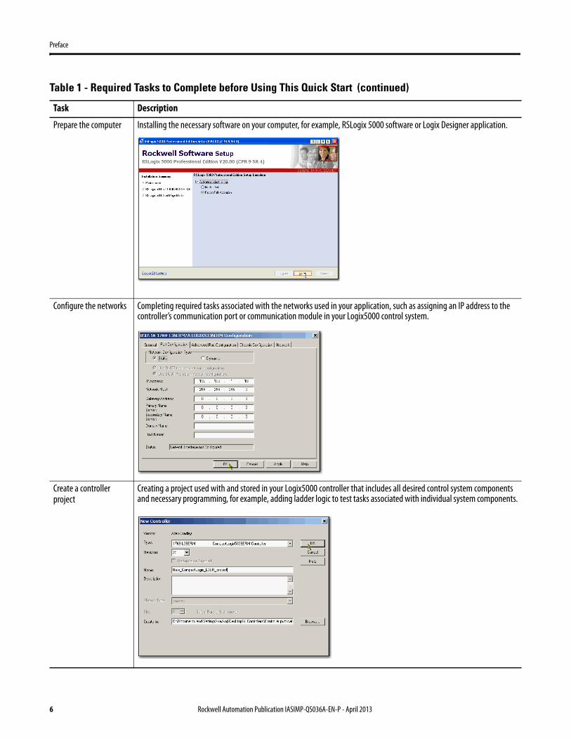
Prepare the computer Installing the necessary software on your computer for example RSLogix 5000 software or Logix Designer application
Configure the networks Completing required tasks associated with the networks used in your application such as assigning an IP address to the controllerrsquos communication port or communication module in your Logix5000 control system
Create a controller project
Creating a project used with and stored in your Logix5000 controller that includes all desired control system components and necessary programming for example adding ladder logic to test tasks associated with individual system components
Table 1 - Required Tasks to Complete before Using This Quick Start (continued)
Task Description
6 Rockwell Automation Publication IASIMP-QS036A-EN-P - April 2013
Preface
Controller and Other Component Quick Starts
This quick start describes how to use one device on one network in a Logix5000 control system Typically though a Logix5000 control system includes more than the controller and one device on one network
For example if a Logix5000 control system operates on an EtherNetIP network in addition to a controller power supply and communication modules the system can use remote IO modules drives and graphic terminals
Other quick starts describe how to use different devices on different networks in Logix5000 control systems For more information see the Integrated Architecturetrade Logix5000 Control Systems Quick Starts Quick Reference publication IASIMP-QR024
Use Each Chapter
The beginning of each chapter contains the following sections of information that must be read before you begin working in the chapter
bull Before You Begin - This section lists the tasks you must complete before starting the chapter
bull What You Need - This section lists the components that are required to complete the tasks in the chapter
bull Follow These Steps - This section illustrates the steps in the current chapter
Rockwell Automation Publication IASIMP-QS036A-EN-P - April 2013 7
Preface
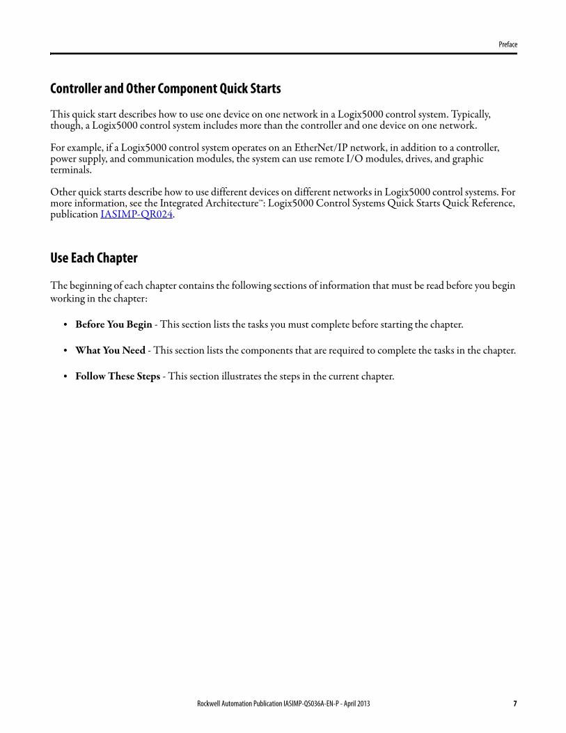
Where to Start
Esc Sel
Add a PowerFlex 525 Drive to a Controller Project on page 19
Prerequisite Tasks Described in Before Using
This Publication on page 5
Logix5000 Controller
Prepare the PowerFlex 525 Drive Hardware on page 11
PowerFlex 525 Drive
8 Rockwell Automation Publication IASIMP-QS036A-EN-P - April 2013
Preface
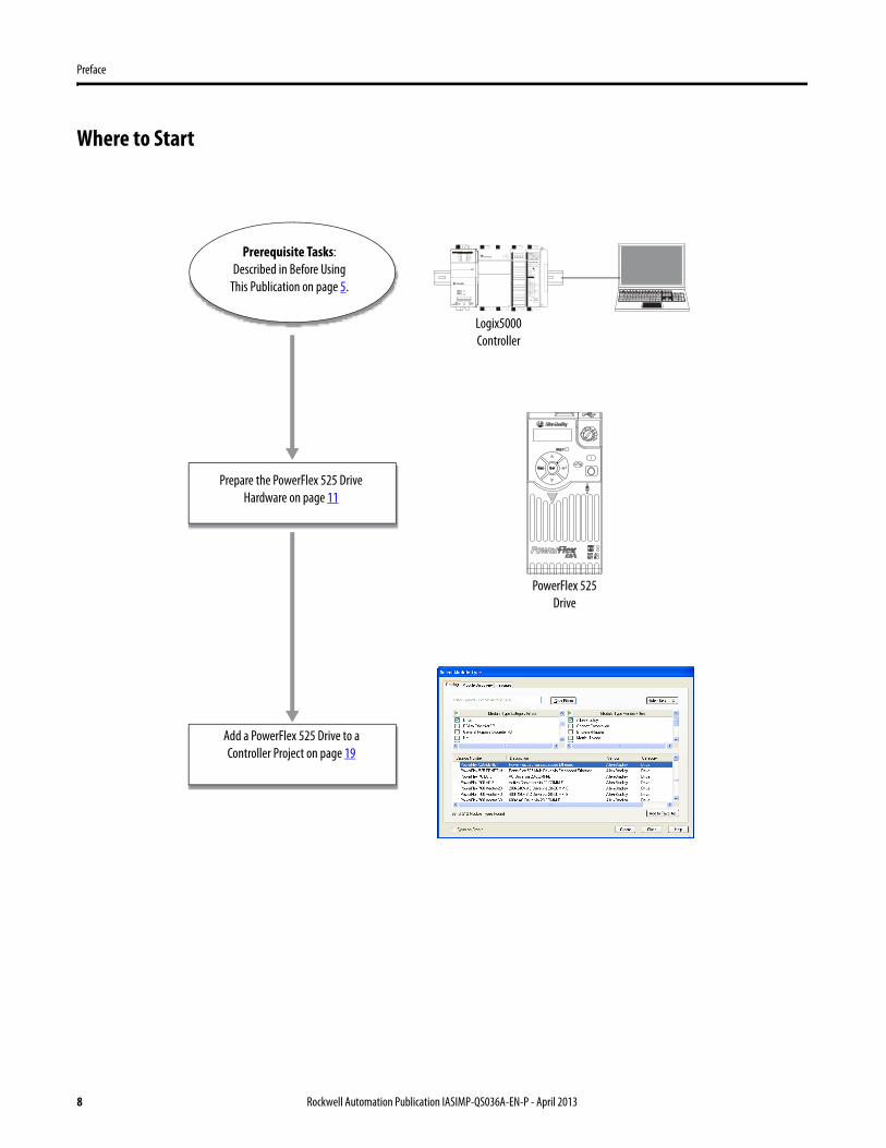
How Hardware is Connected
This quick start demonstrates the following possible control system
Required Software
To complete examples in this quick start you need the software described in this table
Software Required Version Required for This Task
RSLogix 5000 200000 or later(1)
(1) RSLogix 5000 software version 200000 or later is required for use of this quick start because the example Logix5000 controller and associated tasks described herein are completed in a CompactLogix 5370 control system CompactLogix 5370 control systems require RSLogix 5000 software version 200000 or later If you connect a PowerFlex 525 drive over an EtherNetIP network in a Logix5000 control system that uses a different controller the minimum version can differ
Create or change RSLogix 5000 projects to use PowerFlex 525 drive
OR
Studio 5000 Logix Designer 210000 or later Create or change the Studio 5000 Logix Designer project to use PowerFlex 525 drive
BOOTPDHCP utility Version automatically installed with RSLogix 5000 software and varies according to that softwarersquos version
Set IP address for PowerFlex 525 drive
12
34
56
78
Esc Sel
PowerFlex 525 Drive via Embedded EtherNetIP Adapter
Stratix 6000trade Managed Switch
Logix5000 Controller with Ethernet
ConnectionComputer
Rockwell Automation Publication IASIMP-QS036A-EN-P - April 2013 9
Preface
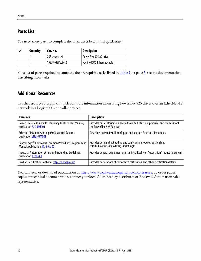
Parts List
You need these parts to complete the tasks described in this quick start
For a list of parts required to complete the prerequisite tasks listed in Table 1 on page 5 see the documentation describing those tasks
Additional Resources
Use the resources listed in this table for more information when using PowerFlex 525 drives over an EtherNetIP network in a Logix5000 controller project
You can view or download publications at httpwwwrockwellautomationcomliterature To order paper copies of technical documentation contact your local Allen-Bradley distributor or Rockwell Automation sales representative
Quantity Cat No Description
1 25B-xyyyN1z4 PowerFlex 525 AC drive
1 1585J-M8PBJM-2 RJ45 to RJ45 Ethernet cable
Resource Description
PowerFlex 525 Adjustable Frequency AC Drive User Manual publication 520-UM001
Provides basic information needed to install start up program and troubleshoot the PowerFlex 525 AC drive
EtherNetIP Modules in Logix5000 Control Systems publication ENET-UM001
Describes how to install configure and operate EtherNetIP modules
ControlLogixreg Controllers Common Procedures Programming Manual publication 1756-PM001
Provides details about adding and configuring modules establishing communication and writing ladder logic
Industrial Automation Wiring and Grounding Guidelines publication 1770-41
Provides general guidelines for installing a Rockwell Automationreg industrial system
Product Certifications website httpwwwabcom Provides declarations of conformity certificates and other certification details
10 Rockwell Automation Publication IASIMP-QS036A-EN-P - April 2013
Chapter 1
Prepare the PowerFlex 525 Drive Hardware
In this chapter you learn how to complete the following tasksbull Mount and wire power to a PowerFlex 525 AC drivebull Configure EtherNetIP communication for the drive
Before You Begin
You must complete these tasks before using this chapterbull The tasks described in Before Using This Publication on page 5
The example controller project used in this chapter uses a CompactLogix 5370 L3 controller
What You Need
This table lists the products you need to complete the tasks described in this chapter
Quantity Cat No Description
1 25B-xyyyN1z4 PowerFlex 525 AC drive
1 1585J-M8PBJM-2 RJ45 to RJ45 Ethernet cable
Rockwell Automation Publication IASIMP-QS036A-EN-P - April 2013 11
Chapter 1 Prepare the PowerFlex 525 Drive Hardware
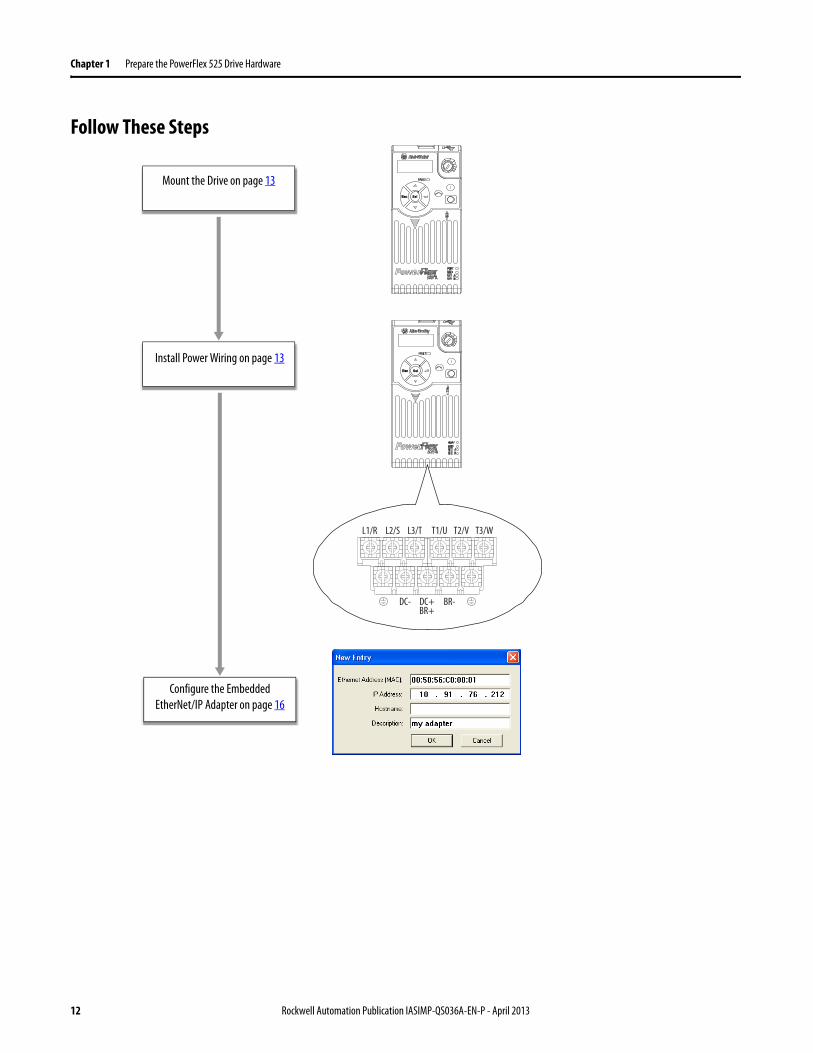
Follow These Steps
Esc Sel
Esc Sel
T2VL3TL2SL1R T1U T3W
BR+BR-DC- DC+
Mount the Drive on page 13
Install Power Wiring on page 13
Configure the Embedded EtherNetIP Adapter on page 16
12 Rockwell Automation Publication IASIMP-QS036A-EN-P - April 2013
Prepare the PowerFlex 525 Drive Hardware Chapter 1
Mount the Drive
The PowerFlex 525 drive must be mounted on a flat vertical and level surface (or DIN rail) following the requirements for minimum clearances ambient operating temperature and debris protection For complete mounting instructions see the PowerFlex 525 Adjustable Frequency AC Drive User Manual publication520-UM001
Install Power Wiring
Follow these steps to access the power terminals and connect the power wires
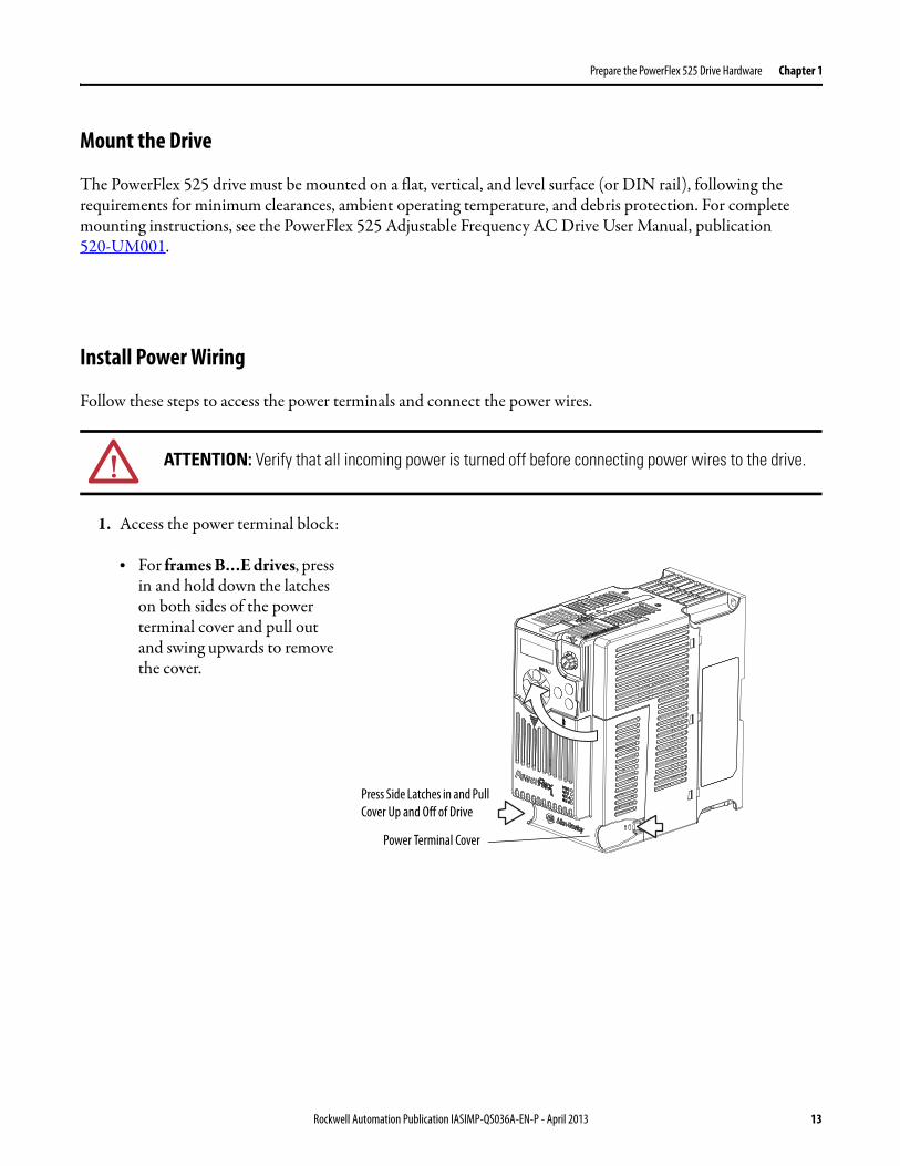
1 Access the power terminal block
bull For frames BhellipE drives press in and hold down the latches on both sides of the power terminal cover and pull out and swing upwards to remove the cover
ATTENTION Verify that all incoming power is turned off before connecting power wires to the drive
Press Side Latches in and Pull Cover Up and Off of Drive
Power Terminal Cover
Rockwell Automation Publication IASIMP-QS036A-EN-P - April 2013 13
Chapter 1 Prepare the PowerFlex 525 Drive Hardware
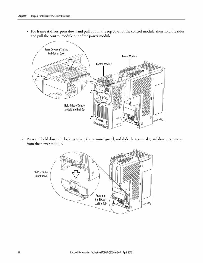
bull For frame A dives press down and pull out on the top cover of the control module then hold the sides and pull the control module out of the power module
2 Press and hold down the locking tab on the terminal guard and slide the terminal guard down to remove from the power module
Press Down on Tab and Pull Out on Cover
Hold Sides of Control Module and Pull Out
Control Module
Power Module
Press and Hold Down Locking Tab
Slide Terminal Guard Down
14 Rockwell Automation Publication IASIMP-QS036A-EN-P - April 2013
Prepare the PowerFlex 525 Drive Hardware Chapter 1
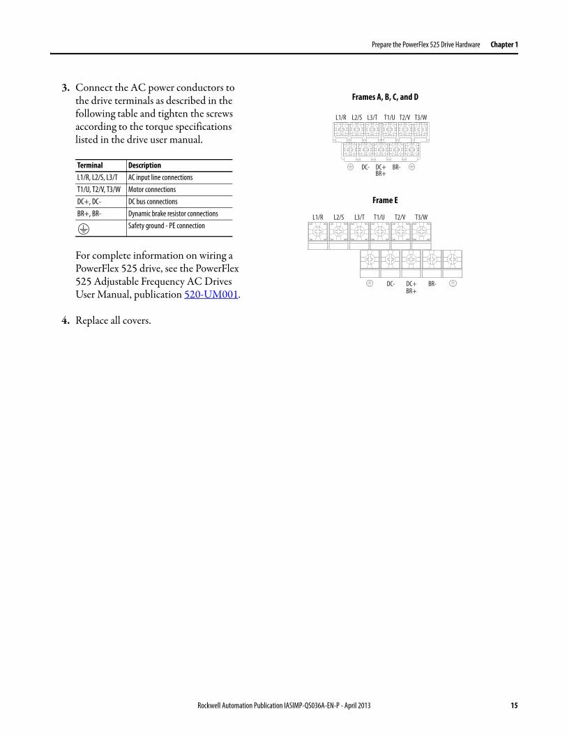
3 Connect the AC power conductors to the drive terminals as described in the following table and tighten the screws according to the torque specifications listed in the drive user manual
For complete information on wiring a PowerFlex 525 drive see the PowerFlex 525 Adjustable Frequency AC Drives User Manual publication 520-UM001
4 Replace all covers
Terminal DescriptionL1R L2S L3T AC input line connectionsT1U T2V T3W Motor connectionsDC+ DC- DC bus connectionsBR+ BR- Dynamic brake resistor connections
Safety ground - PE connectionT2VL3TL2SL1R T1U T3W
T2VL3TL2SL1R T1U T3W
BR+BR-DC- DC+
BR+BR-DC- DC+
Frames A B C and D
Frame E
Rockwell Automation Publication IASIMP-QS036A-EN-P - April 2013 15
Chapter 1 Prepare the PowerFlex 525 Drive Hardware
Configure the Embedded EtherNetIP Adapter
The PowerFlex 525 Embedded EtherNetIP network adapter requires a network IP address to operate on an EtherNetIP network There are two methods for configuring the embedded EtherNetIP adapter IP address
bull BOOTP Server ndash Use BOOTP if you prefer to control the IP addresses of devices with a server The IP address subnet mask and gateway addresses are provided by the BOOTP server BOOTP is enabled by default
bull Adapter Parameters ndash Use adapter parameters when you want more flexibility in setting up the IP address or need to communicate outside of the control network with a gateway The IP address subnet mask and gateway addresses then come from the adapter parameters you set
Follow these steps to configure the Embedded EtherNetIP adapter with the BOOTPDHCP utility
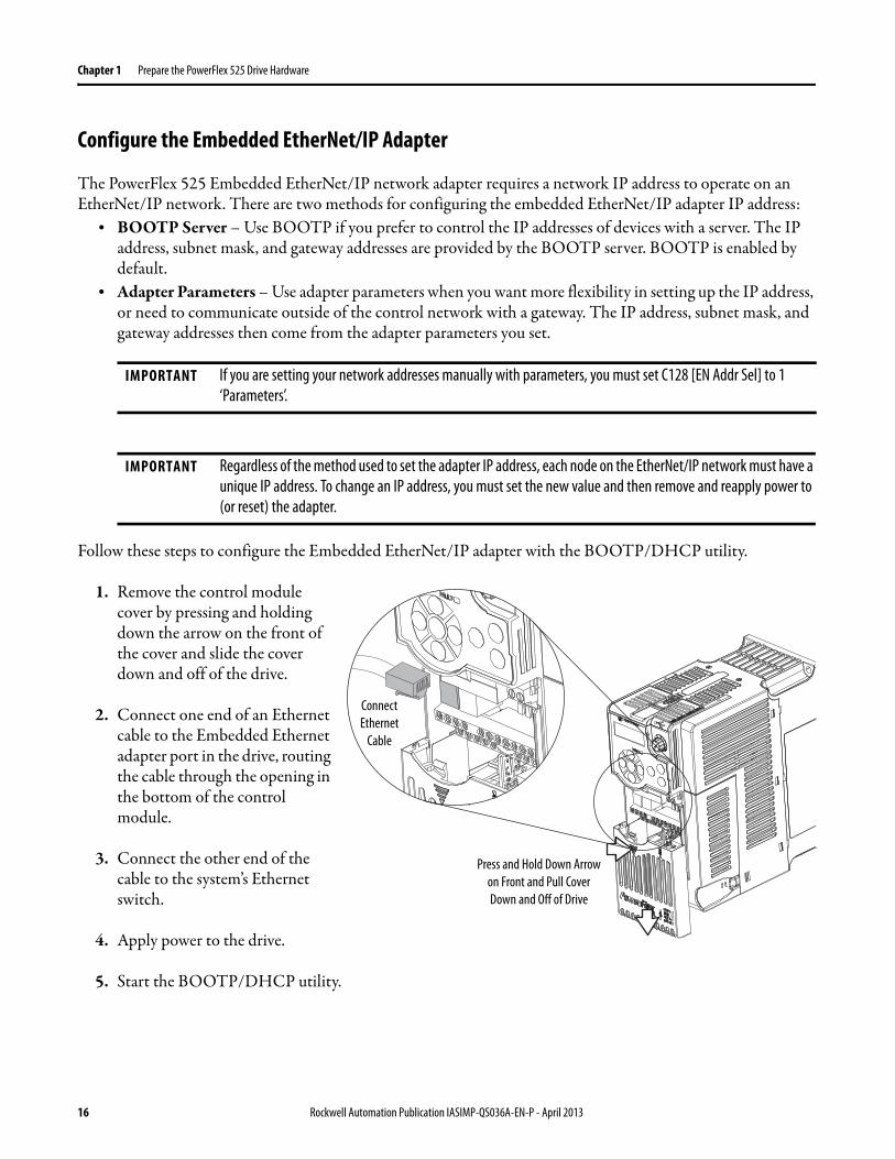
1 Remove the control module cover by pressing and holding down the arrow on the front of the cover and slide the cover down and off of the drive
2 Connect one end of an Ethernet cable to the Embedded Ethernet adapter port in the drive routing the cable through the opening in the bottom of the control module
3 Connect the other end of the cable to the systemrsquos Ethernet switch
4 Apply power to the drive
5 Start the BOOTPDHCP utility
IMPORTANT If you are setting your network addresses manually with parameters you must set C128 [EN Addr Sel] to 1 lsquoParametersrsquo
IMPORTANT Regardless of the method used to set the adapter IP address each node on the EtherNetIP network must have a unique IP address To change an IP address you must set the new value and then remove and reapply power to (or reset) the adapter
Press and Hold Down Arrow on Front and Pull Cover Down and Off of Drive
Connect Ethernet
Cable
16 Rockwell Automation Publication IASIMP-QS036A-EN-P - April 2013
Prepare the PowerFlex 525 Drive Hardware Chapter 1
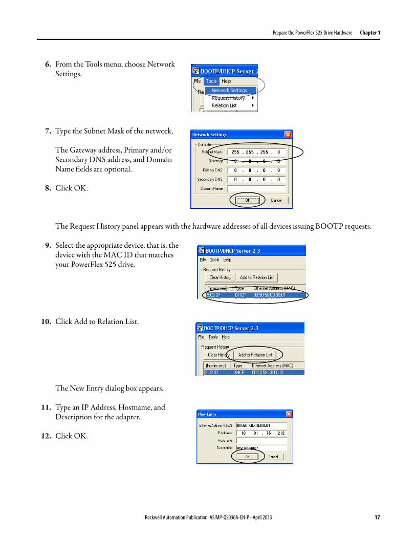
6 From the Tools menu choose Network Settings
7 Type the Subnet Mask of the network
The Gateway address Primary andor Secondary DNS address and Domain Name fields are optional
8 Click OK
The Request History panel appears with the hardware addresses of all devices issuing BOOTP requests
9 Select the appropriate device that is the device with the MAC ID that matches your PowerFlex 525 drive
10 Click Add to Relation List
The New Entry dialog box appears
11 Type an IP Address Hostname and Description for the adapter
12 Click OK
Rockwell Automation Publication IASIMP-QS036A-EN-P - April 2013 17
Chapter 1 Prepare the PowerFlex 525 Drive Hardware
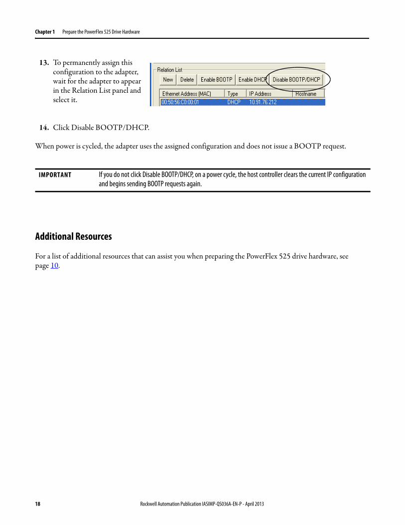
13 To permanently assign this configuration to the adapter wait for the adapter to appear in the Relation List panel and select it
14 Click Disable BOOTPDHCP
When power is cycled the adapter uses the assigned configuration and does not issue a BOOTP request
Additional Resources
For a list of additional resources that can assist you when preparing the PowerFlex 525 drive hardware see page 10
IMPORTANT If you do not click Disable BOOTPDHCP on a power cycle the host controller clears the current IP configuration and begins sending BOOTP requests again
18 Rockwell Automation Publication IASIMP-QS036A-EN-P - April 2013
Chapter 2
Add a PowerFlex 525 Drive to a Controller Project
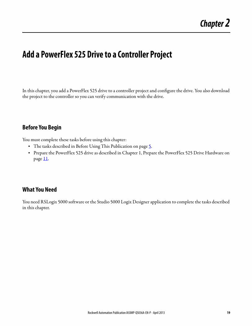
In this chapter you add a PowerFlex 525 drive to a controller project and configure the drive You also download the project to the controller so you can verify communication with the drive
Before You Begin
You must complete these tasks before using this chapterbull The tasks described in Before Using This Publication on page 5bull Prepare the PowerFlex 525 drive as described in Chapter 1 Prepare the PowerFlex 525 Drive Hardware on
page 11
What You Need
You need RSLogix 5000 software or the Studio 5000 Logix Designer application to complete the tasks described in this chapter
Rockwell Automation Publication IASIMP-QS036A-EN-P - April 2013 19
Chapter 2 Add a PowerFlex 525 Drive to a Controller Project
Follow These Steps
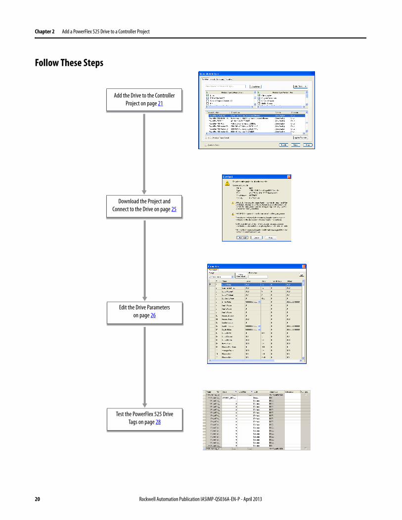
Add the Drive to the Controller Project on page 21
Download the Project and Connect to the Drive on page 25
Edit the Drive Parameters on page 26
Test the PowerFlex 525 Drive Tags on page 28
20 Rockwell Automation Publication IASIMP-QS036A-EN-P - April 2013
Add a PowerFlex 525 Drive to a Controller Project Chapter 2
Add the Drive to the Controller Project
1 Verify that your controller project is offline and the Logix5000 controller is in PROG mode
2 Right-click your network port and choose New Module
The Select Module Type dialog box appears Note that the Select Module Type dialog box can appear differently depending on which Logix5000 controller your application uses and thus what version of controller software is used
3 Select the PowerFlex 525-EENET drive module
4 Check Close on Create at the bottom of the dialog box
5 Click Create
IMPORTANT The tasks described in this section use a RSLogix 5000 project for a CompactLogix 5370 L3 controller CompactLogix 5370 L3 controllers require that you use RSLogix 5000 software version 200000 or later The Studio 5000 Logix Designer application version 2100 or later can also be used The steps are very similar to the RSLogix 5000 project shown in this sectionIf you are using a different Logix5000 controller your projectrsquos RSLogix 5000 software version requirement can be different
RUN
REM
PROG
Rockwell Automation Publication IASIMP-QS036A-EN-P - April 2013 21
Chapter 2 Add a PowerFlex 525 Drive to a Controller Project
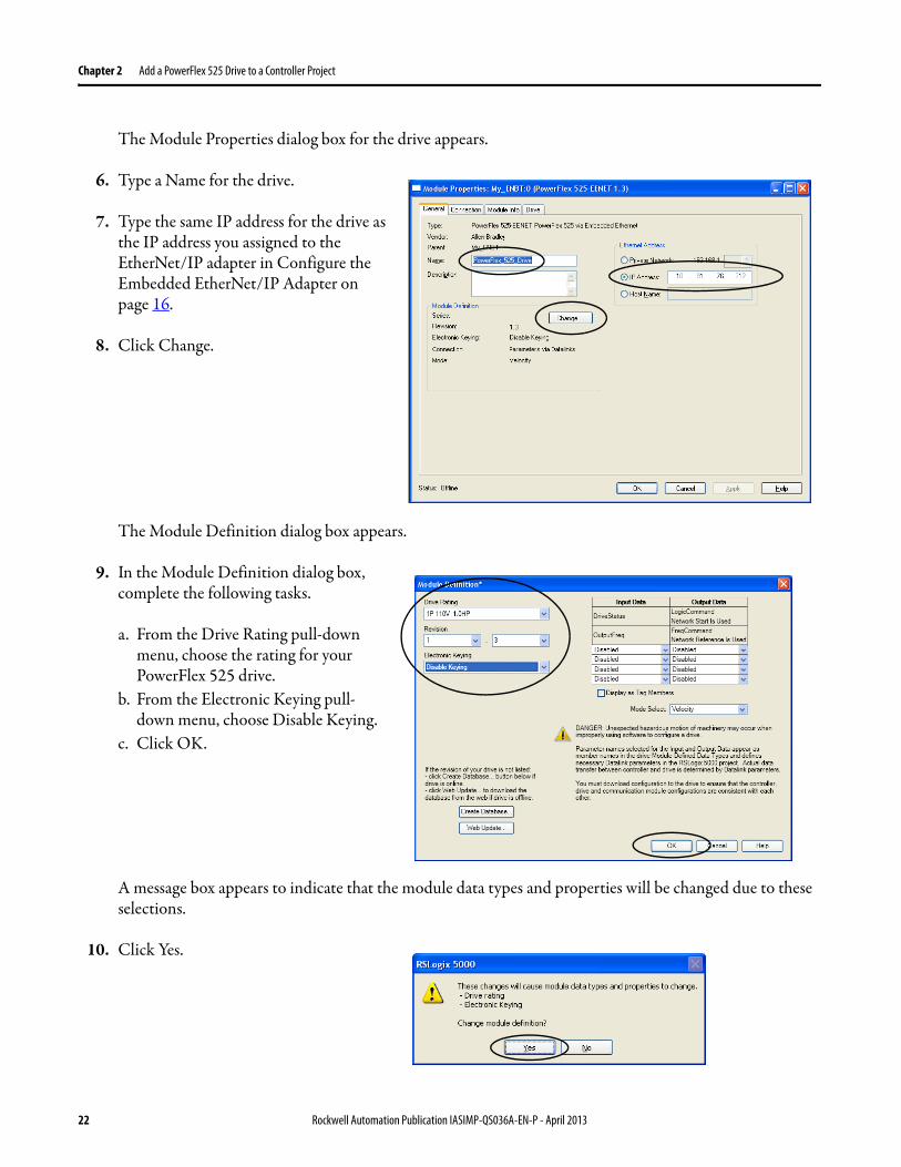
The Module Properties dialog box for the drive appears
6 Type a Name for the drive
7 Type the same IP address for the drive as the IP address you assigned to the EtherNetIP adapter in Configure the Embedded EtherNetIP Adapter on page 16
8 Click Change
The Module Definition dialog box appears
9 In the Module Definition dialog box complete the following tasks
a From the Drive Rating pull-down menu choose the rating for your PowerFlex 525 drive
b From the Electronic Keying pull-down menu choose Disable Keying
c Click OK
A message box appears to indicate that the module data types and properties will be changed due to these selections
10 Click Yes
22 Rockwell Automation Publication IASIMP-QS036A-EN-P - April 2013
Add a PowerFlex 525 Drive to a Controller Project Chapter 2
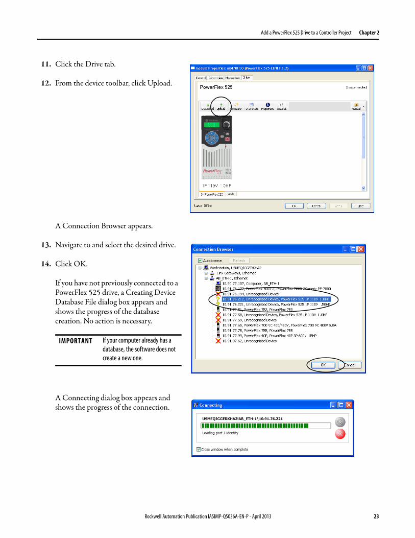
11 Click the Drive tab
12 From the device toolbar click Upload
A Connection Browser appears
13 Navigate to and select the desired drive
14 Click OK
If you have not previously connected to a PowerFlex 525 drive a Creating Device Database File dialog box appears and shows the progress of the database creation No action is necessary
A Connecting dialog box appears and shows the progress of the connection
IMPORTANT If your computer already has a database the software does not create a new one
Rockwell Automation Publication IASIMP-QS036A-EN-P - April 2013 23
Chapter 2 Add a PowerFlex 525 Drive to a Controller Project
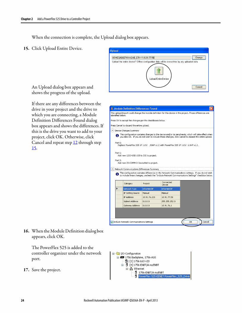
When the connection is complete the Upload dialog box appears
15 Click Upload Entire Device
An Upload dialog box appears and shows the progress of the upload
If there are any differences between the drive in your project and the drive to which you are connecting a Module Definition Differences Found dialog box appears and shows the differences If this is the drive you want to add to your project click OK Otherwise click Cancel and repeat step 12 through step 15
16 When the Module Definition dialog box appears click OK
The PowerFlex 525 is added to the controller organizer under the network port
17 Save the project
24 Rockwell Automation Publication IASIMP-QS036A-EN-P - April 2013
Add a PowerFlex 525 Drive to a Controller Project Chapter 2
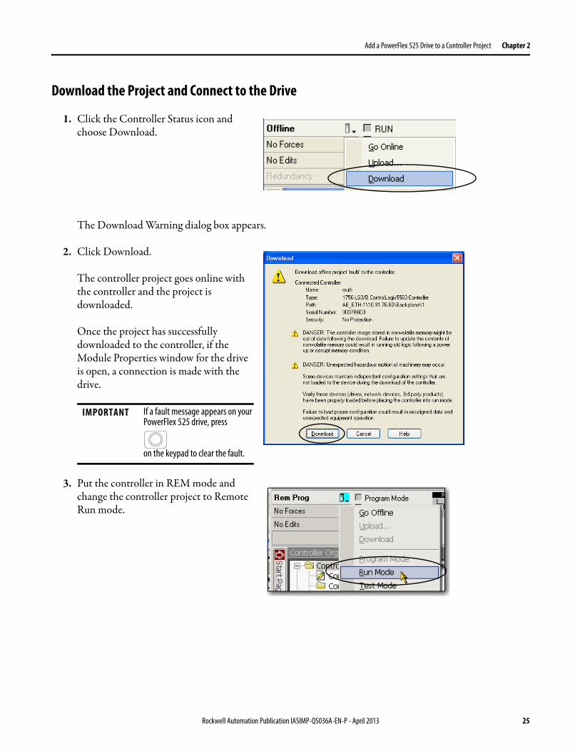
Download the Project and Connect to the Drive
1 Click the Controller Status icon and choose Download
The Download Warning dialog box appears
2 Click Download
The controller project goes online with the controller and the project is downloaded
Once the project has successfully downloaded to the controller if the Module Properties window for the drive is open a connection is made with the drive
3 Put the controller in REM mode and change the controller project to Remote Run mode
IMPORTANT If a fault message appears on your PowerFlex 525 drive press
on the keypad to clear the fault
Rockwell Automation Publication IASIMP-QS036A-EN-P - April 2013 25
Chapter 2 Add a PowerFlex 525 Drive to a Controller Project
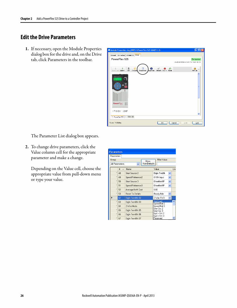
Edit the Drive Parameters
1 If necessary open the Module Properties dialog box for the drive and on the Drive tab click Parameters in the toolbar
The Parameter List dialog box appears
2 To change drive parameters click the Value column cell for the appropriate parameter and make a change
Depending on the Value cell choose the appropriate value from pull-down menu or type your value
26 Rockwell Automation Publication IASIMP-QS036A-EN-P - April 2013
Add a PowerFlex 525 Drive to a Controller Project Chapter 2
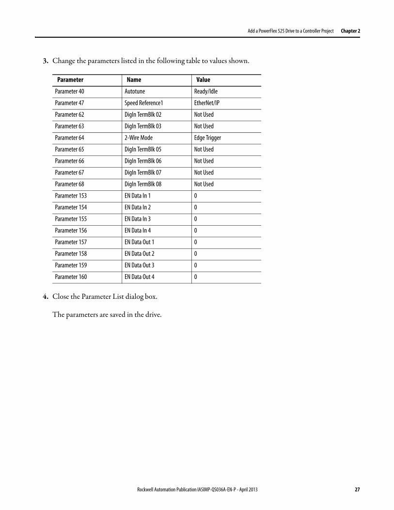
3 Change the parameters listed in the following table to values shown
4 Close the Parameter List dialog box
The parameters are saved in the drive
Parameter Name Value
Parameter 40 Autotune ReadyIdle
Parameter 47 Speed Reference1 EtherNetIP
Parameter 62 DigIn TermBlk 02 Not Used
Parameter 63 DigIn TermBlk 03 Not Used
Parameter 64 2-Wire Mode Edge Trigger
Parameter 65 DigIn TermBlk 05 Not Used
Parameter 66 DigIn TermBlk 06 Not Used
Parameter 67 DigIn TermBlk 07 Not Used
Parameter 68 DigIn TermBlk 08 Not Used
Parameter 153 EN Data In 1 0
Parameter 154 EN Data In 2 0
Parameter 155 EN Data In 3 0
Parameter 156 EN Data In 4 0
Parameter 157 EN Data Out 1 0
Parameter 158 EN Data Out 2 0
Parameter 159 EN Data Out 3 0
Parameter 160 EN Data Out 4 0
Rockwell Automation Publication IASIMP-QS036A-EN-P - April 2013 27
Chapter 2 Add a PowerFlex 525 Drive to a Controller Project
Test the PowerFlex 525 Drive Tags
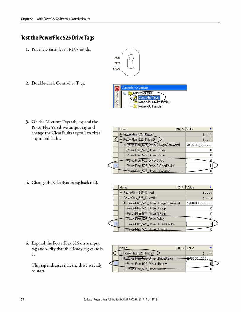
1 Put the controller in RUN mode
2 Double-click Controller Tags
3 On the Monitor Tags tab expand the PowerFlex 525 drive output tag and change the ClearFaults tag to 1 to clear any initial faults
4 Change the ClearFaults tag back to 0
5 Expand the PowerFlex 525 drive input tag and verify that the Ready tag value is 1
This tag indicates that the drive is ready to start
RUN
REM
PROG
28 Rockwell Automation Publication IASIMP-QS036A-EN-P - April 2013
Add a PowerFlex 525 Drive to a Controller Project Chapter 2
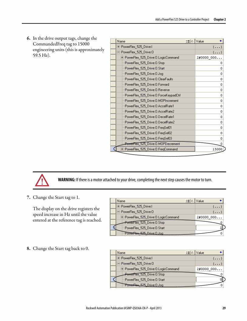
6 In the drive output tags change the CommandedFreq tag to 15000 engineering units (this is approximately 595 Hz)
7 Change the Start tag to 1
The display on the drive registers the speed increase in Hz until the value entered at the reference tag is reached
8 Change the Start tag back to 0
WARNING If there is a motor attached to your drive completing the next step causes the motor to turn
Rockwell Automation Publication IASIMP-QS036A-EN-P - April 2013 29
Chapter 2 Add a PowerFlex 525 Drive to a Controller Project
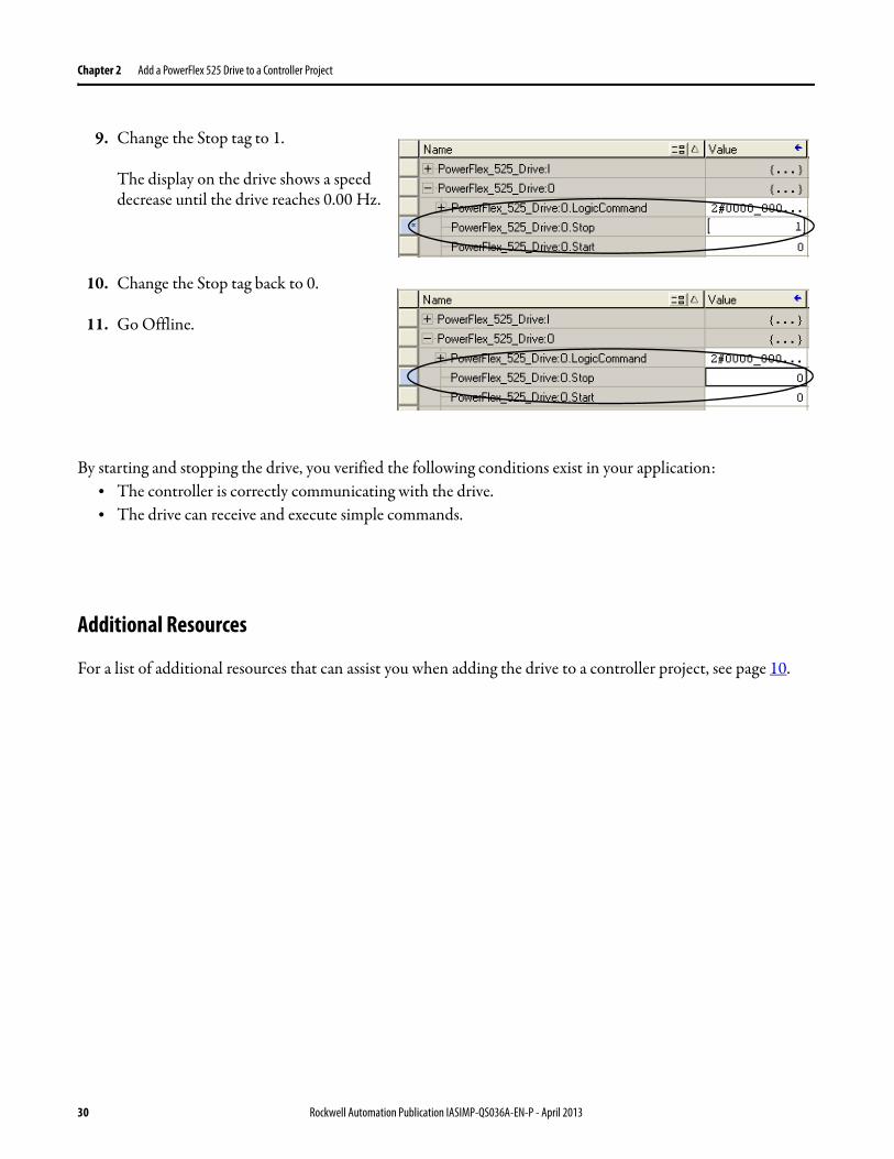
9 Change the Stop tag to 1
The display on the drive shows a speed decrease until the drive reaches 000 Hz
10 Change the Stop tag back to 0
11 Go Offline
By starting and stopping the drive you verified the following conditions exist in your applicationbull The controller is correctly communicating with the drivebull The drive can receive and execute simple commands
Additional Resources
For a list of additional resources that can assist you when adding the drive to a controller project see page 10
30 Rockwell Automation Publication IASIMP-QS036A-EN-P - April 2013
Index
BBOOTPDHCP utility 9 16-18
Cconnections
hardware 9
Ddrive parameters
edit in RSLogix 5000 software 26-27edit in Studio 5000 environment 26-27
drive preparationmount 13wire power 13
drive tagstest in RSLogix 5000 software 28-30test in Studio 5000 environment 28-30
Eenvironment
Studio 5000 9 21-30Ethernet adapter
assign IP address 16-18
Hhardware
example control system 9mount drive 13preparation 11wire power 13
IIP address
assign to drive 22assign to Ethernet adapter 16-18
Studio 5000 environmentadd drive to project 19-30edit drive parameters 26-27requirements 9test drive tags 28-30
Rockwell Automation Publication IASIMP-QS036A-EN-P - April 2013 31
Index
32 Rockwell Automation Publication IASIMP-QS036A-EN-P - April 2013
Rockwell Otomasyon Ticaret AŞ Kar Plaza İş Merkezi E Blok Kat6 34752 İccedilerenkoumly İstanbul Tel +90 (216) 5698400
Publication IASIMP-QS036A-EN-P - April 2013Copyright copy 2013 Rockwell Automation Inc All rights reserved Printed in the USA
Rockwell Automation Support
Rockwell Automation provides technical information on the Web to assist you in using its products At httpwwwrockwellautomationcomsupport you can find technical manuals a knowledge base of FAQs technical and application notes sample code and links to software service packs and a MySupport feature that you can customize to make the best use of these tools
For an additional level of technical phone support for installation configuration and troubleshooting we offer TechConnectSM support programs For more information contact your local distributor or Rockwell Automation representative or visit httpwwwrockwellautomationcomsupport
Installation Assistance
If you experience a problem within the first 24 hours of installation review the information that is contained in this manual You can contact Customer Support for initial help in getting your product up and running
New Product Satisfaction Return
Rockwell Automation tests all of its products to ensure that they are fully operational when shipped from the manufacturing facility However if your product is not functioning and needs to be returned follow these procedures
Documentation Feedback
Your comments will help us serve your documentation needs better If you have any suggestions on how to improve this document complete this form publication RA-DU002 available at httpwwwrockwellautomationcomliterature
United States or Canada 14406463434
Outside United States or Canada Use the Worldwide Locator at httpwwwrockwellautomationcomsupportamericasphone_enhtml or contact your local Rockwell Automation representative
United States Contact your distributor You must provide a Customer Support case number (call the phone number above to obtain one) to your distributor to complete the return process
Outside United States Please contact your local Rockwell Automation representative for the return procedure
Power Control and Information Solutions HeadquartersAmericas Rockwell Automation 1201 South Second Street Milwaukee WI 53204-2496 USA Tel (1) 4143822000 Fax (1) 4143824444
EuropeMiddle EastAfrica Rockwell Automation NV Pegasus Park De Kleetlaan 12a 1831 Diegem Belgium Tel (32) 2 663 0600 Fax (32) 2 663 0640
Asia Pacific Rockwell Automation Level 14 Core F Cyberport 3 100 Cyberport Road Hong Kong Tel (852) 2887 4788 Fax (852) 2508 1846
wwwrockwel lautomationcom
Logix5000 Control Systems Connect PowerFlex 525 Drives over an EtherNetIP Network Quick Start
Table of Contents
Preface
About This Publication
Before Using This Publication
Controller and Other Component Quick Starts
Use Each Chapter
Where to Start
How Hardware is Connected
Required Software
Parts List
Additional Resources
Chapter 1 - Prepare the PowerFlex 525 Drive Hardware
Before You Begin
What You Need
Follow These Steps
Mount the Drive
Install Power Wiring
Configure the Embedded EtherNetIP Adapter
Additional Resources
Chapter 2 - Add a PowerFlex 525 Drive to a Controller Project
Select Print Category ABC or D from category list on Introduction_Catagory Types tab
11rdquo x 17rdquo
LOOSE -Loose Leaf
YES
Pre-sale Marketing
TOP
(required) Finished Trim Size Width
85rdquo x 11rdquo
85rdquo x 11rdquo
PERFECT - Perfect Bound
A1
LEFT
(required) Publication Number
IASIMP-QS036A-EN-P
Sample 2030-SP001B-EN-P
3rdquo x 5rdquo
SADDLE - Saddle Stitch
A2
RIGHT
CORNER
Use Legacy Number
NO
YES or NO
18rdquo x 24rdquo Poster
PLASTCOIL - Plastic Coil (Coil Bound)
A4
BOTTOM
SIDE
Legacy Number if applicable
Sample Legacy Number 0160-533
24rdquo x 36rdquo Poster
STAPLED1 -1 position
A3
Publication Title
Logix5000 Control Systems Connect PowerFlex 525 Drives over an EtherNetIP Network Quick Start
Sample ElectroGuard Selling Brief80 character limit - must match DocMan Title
36rdquo x 24rdquo Poster
STAPLED1B - bottom 1 position
A5
(required) Business Group
Marketing Commercial
As entered in DocMan
4rdquo x 6rdquo
STAPLED2 - 2 positions
A6
(required) Cost Center
19134 - IA
When Business Unit is Marketing Commercial enter Cost Center as shown on chart on left All other Business Units As entered in DocMan - enter number only no description Example - 19021
0000000 - My co 19134 - Commerc 19134 - Compone 19134 - Global 19134 - IA 19134 - IMC 19134 - Industr 19134 - Mkt Dig 19134 - OEM 19134 - Power C 19134 - Process 19134 - Service 19134 - Safety 19134 - Softwar 19134 - US Marke
475rdquo x 7rdquo (slightly smaller half-size)
THERMAL - Thermal bound (Tape bound)
A7
BindingStitching
SADDLE - Saddle Stitch
Review key on right
Saddle-Stitch Items All page quantities must be divisible by 4Note Stitching is implied for Saddle-Stitch - no need to specify in Stitching Location80 pgs max on 20 (text and cover)76 pgs max on 20 (text) and 24 (cover)72 pgs max on 24 (text and cover)Perfect Bound Items940 pgs max wcover (90 index unless indicated otherwise)70 pgs min for spine without words200 pgs min for spine with words Plastcoil Bound Items530 pgs max of 20 (if adding cover deduct equivalent number of pages to equal cover thickness) (90 index unless indicated otherwise)Tape Bound Items250 pgs max on 20 no cover240 pgs max wcover (90 index unless indicated otherwise)
475rdquo x 775rdquo
THERMALO - Thermal Bound (Tape bound - offline)
A8
(required) Page Count of Publication
36
Total page count including cover
55rdquo x 85rdquo (half-size)
A9
Paper Stock Color
White is assumed For color options contact your vendor
6rdquo x 4rdquo
Post Sale Technical Communication
Number of Tabs Needed
5 tab in stock at RR Donnelley
7385rdquo x 9rdquo (RSI Std)
B1
Stitching Location
SIDE
Blank Corner or Side
825rdquo x 10875rdquo
B2
Drill Hole YESNO
YES
All drilled publications use the 5-hole standard 516 inch-size hole and a minimum of frac14 inch from the inner page border
825rdquo x 11rdquo (RA product profile std)
B3
None
Glue Location on Pad
Glue location on pads
8375rdquo x 10875
B4
Half or V or Single Fold
Number of Pages per Pad
Average sheets of paper 25 50 75100 Max
9rdquo x 12rdquo (Folder)
B5
C or Tri-Fold
Ink Color
One color assumes BLACK 4 color assume CMYK Indicate PMS number herehellip
A4 (8 frac14rdquo x 11 frac34rdquo) (210 x 297 mm)
Catalogs
DbleParll
Used in Manufacturing
NO
A5 (583rdquo x 826rdquo) (148 x 210 mm)
C1
Sample
Fold
None
Review key on right
Short (must specify dimensions between folds in Comments)
Comments
C2
Z or Accordian Fold
Part Number
JIT POD
Microfold or French Fold - designate no of folds in Comments - intended for single sheet only to be put in box for manufacturing
D1
Double Gate
D2
FoldsHalf V Single C or TriDble ParllZ or Accordian Microfold or FrenchDouble Gate Short Fold
D3
D4
D5
D6
D7
D8
D9
This tab summarizes Rockwell Automation Global Sales and Marketing preferred printing standards It also provides guidance on whether a publication should be released as JIT (print on demand) or if it requires an RFQ for offset printingFind your publication type in the first section below Use the assigned Printing Category information to determine the standard print specifications for that document type The Printing Categories are defined below the Publication Type section Note there may be slightly different print specifications for the categories depending on the region (EMEA or Americas)For more information on Global Sales and Marketing Printing Standards see publication RA-CO004 in DocMan
Publication Type and Print Category
Publication Type
Off Set Print Category Spec (See table below)
JIT Spec (See table below)
Description
Order Min
Order Max
Life Cycle Usage Release Option
AD
NA - Puttman
NA
Advertisement Reprint Colour
NA
NA
Presale Internal
AP
A3
D2
Application Solution or Customer Success Story
5
100
Presale External
AR
NA
NA
ArticleEditorialByline
NA
NA
Presale Internal
(press releases should not be checked into DocMan or printed)
AT
B3 B4
D5
Application techniques
5
100
Presale External
BR
A2 Primary A1
NA
Brochures
5
100
Presale External
CA
C2 Primary C1
NA
Catalogue
1
50
Presale External
CG
NA
NA
Catalogue Guide
1
50
Presale External
CL
NA
NA
Collection
5
50
Presale External
CO
A5 A6 A9
D5
Company Confidential Information
NA
NA
NA Confidential
CP
E-only
E-only D5
Competitive Information
5
50
NA Confidential
DC
E-only
E-only
Discount Schedules
NA
NA
Presale Internal
DI
A1 A3
NA
Direct Mail
5
100
Presale Internal
DM
NA
NA
Product Demo
5
50
Presale Internal
DS
B3
D5
Dimensions Sheet
1
5
Post External
DU
B3
D5
Document Update
1
5
Post External
GR
B2
D6
Getting Results
1
5
Post External
IN
B3 Primary B2
D5 D6
Installation instructions
1
5
Post External
LM
NA
NA
Launch Materials
5
50
Presale Internal
PC
B3
D5
Packaging Contents
PL
E-only primary B3
E-only
Price List
5
50
Presale Internal
PM
B2
D6
Programming Manual
1
5
Post External
PP
A3
D1
Profile (Single Product or Service) NOTE Application Solutions are to be assigned the AP pub type
5
100
Presale External
QR
B2 primary B3 B5
D5 D6
Quick Reference
1
5
Post External
QS
B2 primary B3 B5
D5 D6
Quick Start
1
5
Post External
RM
B2
D5 D6
Reference Manual
1
5
Post External
RN
B3
D5
Release Notes
1
5
Post External
SG
B1 Primary B4
D5 D6
Selection Guide Colour
5
50
Presale External
SG
B2
D5 D6
Selection Guide BW
5
50
Presale External
SP
A1 A2 A3 A4
NA
Sales Promotion NOTE Service profiles are to be assigned the PP pub type
5
100
Presale Internal
SR
B2 B3
D5 D6
Specification Rating Sheet
5
100
Presale External
TD
B2 Primary B3 B4 B5
D5 D6
Technical Data
5
50
Presale External
TG
B2 B3
D6
Troubleshooting Guide
1
5
Post External
UM
B2 Primary B4
D6
User Manual BW
1
5
Post External
WD
B3
D5
Wiring Diagrams Dwgs
1
5
Post Internal
WP
B3 Primary B5
D5
White Paper
5
50
Presale External
Minimum order quantities on all JIT items are based on the publication length
Publication length
Minimum Order Quantity
77 or more pages
1 (no shrink wrap required)
33 to 76 pages
25
3 to 32 pages
50
1 or 2 pages
100
Pre-sale Marketing
All paper in this category is White Brightness 90 or better Opacity 90 or better
Category
Color Options
AP EMEA Paper Requirements
Canada LA US Paper Requirements
A1
4 color
170 gsm 2pp
100 gloss cover 100 gloss text
A2
4 color
170 gsm folded 4pp
100 gloss cover 80 gloss text
A3
4 color
Cover 170 gsm with Body 120 gsm gt 4pp
80 gloss cover 80 gloss text
A4
2 color
170gsm Silk ndash 120gsm Silk
80 gloss cover 80 gloss text
A5
2 color
170gsm Silk ndash 120gsm Silk
80 gloss cover 80 matt sheet text
A6
1 color
170gsm Silk ndash 120gsm Silk
80 gloss cover 80 matt sheet text
A7
4 color cover2 color textSelection Guide
Category being deleted
10 Point Cover C2S50 matte sheet text
A8
4 color cover
Category being deleted
50 matte sheet text self cover
2 color text
Selection Guide
A9
2 color
100gsm bond
50 matte sheet text self cover
Selection Guide
Gray shading indicates Obsolete Print Catagories
Post Sale Technical Communication
Category
Color Options
AP EMEA Paper Requirements
Canada LA US Paper Requirements
B1
4 color cover
270gsm Gloss 100gsm bond
10 Point Cover C2S
2 color text
50 matte sheet text
B2
1 color
160gsm Colortech amp 100gsm Bond
90 Cover50 matte sheet text
B3
1 color
100gsm bond
50 matte sheet text self cover
B4
2 color
160gsm Colortech amp 100gsm Bond
90 Cover50 matte sheet text
B5
2 color
100gsm bond
50 matte sheet text self cover
Catalogs
Category
Color Options
AP EMEA Paper Requirements
Canada LA US Paper Requirements
C1
4 color cover
270gsm Gloss 90gsm silk
10 Point Cover C2S
4 color text
45 Coated Sheet
C2
4 color cover
270gsm Gloss 80gsm silk
10 Point Cover C2S
2 color text
32-33 Coated Sheet
JIT POD
All paper in this category is White Brightness 82 or better Opacity 88 or better
Category
Color Options
AP EMEA Paper Requirements
Canada LA US Paper Requirements
D1
4 color
170gsm white silk
80 gloss cover coated 2 sides
D2
4 color
120gsm white silk
80 gloss text coated 2 sides self cover
D3
4 color
Cover 170gsm with Body 120gsm
80 gloss cover 80 gloss text coated 2 sides
D4
1 color
160gsm tab
90 index
D5
1 color
80gsm bond
20 bond self cover
D6
1 color
Cover 160gsm tab with Body 80gsm bond
90 index 20 bond
D7
2 color
160gsm tab
90 index
D8
2 color
80gsm bond
20 bond self cover
D9
2 color
Cover 160gsm tab with Body 80gsm bond
90 index 20 bond
D10
Combination 4 color cover with 2 color body
Cover 160gsm with Body 80gsm
90 index 20 bond
Gray shading indicates Obsolete Print Catagories
Just In Time (JIT) or Off Set (OS)
Use these guidelines to determine if your publication should be JIT (just in timeprint on demand) or if it would be more economical to print OS (offseton a press) OS print jobs require an RFQ (Request For Quote) in US If your job fits into the ldquoEitherrdquo category an RFQ is recommended but not required In the US RA Strategic Sourcing will discourage or reject RFQs for jobs that fall within the JIT category Guidelines differ for black amp white and color printing so be sure to check the correct tables
Black amp White Printing
Color Printing
Color Printing
Important User Information
Solid-state equipment has operational characteristics differing from those of electromechanical equipment Safety Guidelines for the Application Installation and Maintenance of Solid State Controls (publication SGI-11 available from your local Rockwell Automation sales office or online at httpwwwrockwellautomationcomliterature) describes some important differences between solid-state equipment and hard-wired electromechanical devices Because of this difference and also because of the wide variety of uses for solid-state equipment all persons responsible for applying this equipment must satisfy themselves that each intended application of this equipment is acceptable
In no event will Rockwell Automation Inc be responsible or liable for indirect or consequential damages resulting from the use or application of this equipment
The examples and diagrams in this manual are included solely for illustrative purposes Because of the many variables and requirements associated with any particular installation Rockwell Automation Inc cannot assume responsibility or liability for actual use based on the examples and diagrams
No patent liability is assumed by Rockwell Automation Inc with respect to use of information circuits equipment or software described in this manual
Reproduction of the contents of this manual in whole or in part without written permission of Rockwell Automation Inc is prohibited
Throughout this manual when necessary we use notes to make you aware of safety considerations
Allen-Bradley CompactLogix ControlLogix Integrated Architecture Logix5000 PowerFlex Rockwell Software Rockwell Automation RSLogix RSLinx Stratix 6000 Studio 5000 and TechConnect are trademarks of Rockwell Automation Inc
Trademarks not belonging to Rockwell Automation are property of their respective companies
WARNING Identifies information about practices or circumstances that can cause an explosion in a hazardous environment which may lead to personal injury or death property damage or economic loss
ATTENTION Identifies information about practices or circumstances that can lead to personal injury or death property damage or economic loss Attentions help you identify a hazard avoid a hazard and recognize the consequence
SHOCK HAZARD Labels may be on or inside the equipment for example a drive or motor to alert people that dangerous voltage may be present
BURN HAZARD Labels may be on or inside the equipment for example a drive or motor to alert people that surfaces may reach dangerous temperatures
IMPORTANT Identifies information that is critical for successful application and understanding of the product
Table of Contents
PrefaceAbout This Publication 5Before Using This Publication 5Controller and Other Component Quick Starts 7Use Each Chapter 7Where to Start 8How Hardware is Connected 9Required Software 9Parts List 10Additional Resources 10
Chapter 1Prepare the PowerFlex 525 Drive Hardware
Before You Begin 11What You Need 11Follow These Steps 12Mount the Drive 13Install Power Wiring 13Configure the Embedded EtherNetIP Adapter 16Additional Resources 18
Chapter 2Add a PowerFlex 525 Drive to a Controller Project
Before You Begin 19What You Need 19Follow These Steps 20Add the Drive to the Controller Project 21Download the Project and Connect to the Drive 25Edit the Drive Parameters 26Test the PowerFlex 525 Drive Tags 28Additional Resources 30
Index
Rockwell Automation Publication IASIMP-QS036A-EN-P - April 2013 3
Table of Contents
4 Rockwell Automation Publication IASIMP-QS036A-EN-P - April 2013
Preface
About This Publication
This quick start provides examples and procedures for including a PowerFlexreg 525 drive in a Logix5000trade control system over an EtherNetIP network The programming examples are not complex and offer easy solutions to verify that devices are communicating and functioning properly
Before Using This Publication
You can complete the tasks described in this publication only after first completing some prerequisite tasks with a Logix5000 controller For example before you can add a PowerFlex 525 drive to an RSLogixtrade 5000 or Studio 5000trade Logix Designer application project as described on page 19 you must first create the project in a Logix5000 controller
Table 1 describes the tasks you must complete before using this publication
IMPORTANT This publication describes example tasks you complete when using a PowerFlex 525 drive on an EtherNetIP network The tasks described are not the only tasks you can complete with the PowerFlex 525 drive on an EtherNetIP network
IMPORTANT The example graphics shown in the table are for CompactLogixtrade 5370 L3 controllers Depending on the Logix5000 controller you are using the specific steps to complete the tasks described in the table can vary
Table 1 - Required Tasks to Complete before Using This Quick Start
Task Description
Prepare the Logix5000 control system hardware
Assembling the control system and connecting to communication networks Some components for example the Logix5000 controller and system power supply are required Other components for example a network communication module are optional
These example graphics show the assembly of one Logix5000 controller
2 (Rear)
1 (Front)
IMPORTANT This task does not include installation of specific hardware components for example PowerFlex 525 drives used over the networks included in your application
Rockwell Automation Publication IASIMP-QS036A-EN-P - April 2013 5
Preface
Prepare the computer Installing the necessary software on your computer for example RSLogix 5000 software or Logix Designer application
Configure the networks Completing required tasks associated with the networks used in your application such as assigning an IP address to the controllerrsquos communication port or communication module in your Logix5000 control system
Create a controller project
Creating a project used with and stored in your Logix5000 controller that includes all desired control system components and necessary programming for example adding ladder logic to test tasks associated with individual system components
Table 1 - Required Tasks to Complete before Using This Quick Start (continued)
Task Description
6 Rockwell Automation Publication IASIMP-QS036A-EN-P - April 2013
Preface
Controller and Other Component Quick Starts
This quick start describes how to use one device on one network in a Logix5000 control system Typically though a Logix5000 control system includes more than the controller and one device on one network
For example if a Logix5000 control system operates on an EtherNetIP network in addition to a controller power supply and communication modules the system can use remote IO modules drives and graphic terminals
Other quick starts describe how to use different devices on different networks in Logix5000 control systems For more information see the Integrated Architecturetrade Logix5000 Control Systems Quick Starts Quick Reference publication IASIMP-QR024
Use Each Chapter
The beginning of each chapter contains the following sections of information that must be read before you begin working in the chapter
bull Before You Begin - This section lists the tasks you must complete before starting the chapter
bull What You Need - This section lists the components that are required to complete the tasks in the chapter
bull Follow These Steps - This section illustrates the steps in the current chapter
Rockwell Automation Publication IASIMP-QS036A-EN-P - April 2013 7
Preface
Where to Start
Esc Sel
Add a PowerFlex 525 Drive to a Controller Project on page 19
Prerequisite Tasks Described in Before Using
This Publication on page 5
Logix5000 Controller
Prepare the PowerFlex 525 Drive Hardware on page 11
PowerFlex 525 Drive
8 Rockwell Automation Publication IASIMP-QS036A-EN-P - April 2013
Preface
How Hardware is Connected
This quick start demonstrates the following possible control system
Required Software
To complete examples in this quick start you need the software described in this table
Software Required Version Required for This Task
RSLogix 5000 200000 or later(1)
(1) RSLogix 5000 software version 200000 or later is required for use of this quick start because the example Logix5000 controller and associated tasks described herein are completed in a CompactLogix 5370 control system CompactLogix 5370 control systems require RSLogix 5000 software version 200000 or later If you connect a PowerFlex 525 drive over an EtherNetIP network in a Logix5000 control system that uses a different controller the minimum version can differ
Create or change RSLogix 5000 projects to use PowerFlex 525 drive
OR
Studio 5000 Logix Designer 210000 or later Create or change the Studio 5000 Logix Designer project to use PowerFlex 525 drive
BOOTPDHCP utility Version automatically installed with RSLogix 5000 software and varies according to that softwarersquos version
Set IP address for PowerFlex 525 drive
12
34
56
78
Esc Sel
PowerFlex 525 Drive via Embedded EtherNetIP Adapter
Stratix 6000trade Managed Switch
Logix5000 Controller with Ethernet
ConnectionComputer
Rockwell Automation Publication IASIMP-QS036A-EN-P - April 2013 9
Preface
Parts List
You need these parts to complete the tasks described in this quick start
For a list of parts required to complete the prerequisite tasks listed in Table 1 on page 5 see the documentation describing those tasks
Additional Resources
Use the resources listed in this table for more information when using PowerFlex 525 drives over an EtherNetIP network in a Logix5000 controller project
You can view or download publications at httpwwwrockwellautomationcomliterature To order paper copies of technical documentation contact your local Allen-Bradley distributor or Rockwell Automation sales representative
Quantity Cat No Description
1 25B-xyyyN1z4 PowerFlex 525 AC drive
1 1585J-M8PBJM-2 RJ45 to RJ45 Ethernet cable
Resource Description
PowerFlex 525 Adjustable Frequency AC Drive User Manual publication 520-UM001
Provides basic information needed to install start up program and troubleshoot the PowerFlex 525 AC drive
EtherNetIP Modules in Logix5000 Control Systems publication ENET-UM001
Describes how to install configure and operate EtherNetIP modules
ControlLogixreg Controllers Common Procedures Programming Manual publication 1756-PM001
Provides details about adding and configuring modules establishing communication and writing ladder logic
Industrial Automation Wiring and Grounding Guidelines publication 1770-41
Provides general guidelines for installing a Rockwell Automationreg industrial system
Product Certifications website httpwwwabcom Provides declarations of conformity certificates and other certification details
10 Rockwell Automation Publication IASIMP-QS036A-EN-P - April 2013
Chapter 1
Prepare the PowerFlex 525 Drive Hardware
In this chapter you learn how to complete the following tasksbull Mount and wire power to a PowerFlex 525 AC drivebull Configure EtherNetIP communication for the drive
Before You Begin
You must complete these tasks before using this chapterbull The tasks described in Before Using This Publication on page 5
The example controller project used in this chapter uses a CompactLogix 5370 L3 controller
What You Need
This table lists the products you need to complete the tasks described in this chapter
Quantity Cat No Description
1 25B-xyyyN1z4 PowerFlex 525 AC drive
1 1585J-M8PBJM-2 RJ45 to RJ45 Ethernet cable
Rockwell Automation Publication IASIMP-QS036A-EN-P - April 2013 11
Chapter 1 Prepare the PowerFlex 525 Drive Hardware
Follow These Steps
Esc Sel
Esc Sel
T2VL3TL2SL1R T1U T3W
BR+BR-DC- DC+
Mount the Drive on page 13
Install Power Wiring on page 13
Configure the Embedded EtherNetIP Adapter on page 16
12 Rockwell Automation Publication IASIMP-QS036A-EN-P - April 2013
Prepare the PowerFlex 525 Drive Hardware Chapter 1
Mount the Drive
The PowerFlex 525 drive must be mounted on a flat vertical and level surface (or DIN rail) following the requirements for minimum clearances ambient operating temperature and debris protection For complete mounting instructions see the PowerFlex 525 Adjustable Frequency AC Drive User Manual publication520-UM001
Install Power Wiring
Follow these steps to access the power terminals and connect the power wires
1 Access the power terminal block
bull For frames BhellipE drives press in and hold down the latches on both sides of the power terminal cover and pull out and swing upwards to remove the cover
ATTENTION Verify that all incoming power is turned off before connecting power wires to the drive
Press Side Latches in and Pull Cover Up and Off of Drive
Power Terminal Cover
Rockwell Automation Publication IASIMP-QS036A-EN-P - April 2013 13
Chapter 1 Prepare the PowerFlex 525 Drive Hardware
bull For frame A dives press down and pull out on the top cover of the control module then hold the sides and pull the control module out of the power module
2 Press and hold down the locking tab on the terminal guard and slide the terminal guard down to remove from the power module
Press Down on Tab and Pull Out on Cover
Hold Sides of Control Module and Pull Out
Control Module
Power Module
Press and Hold Down Locking Tab
Slide Terminal Guard Down
14 Rockwell Automation Publication IASIMP-QS036A-EN-P - April 2013
Prepare the PowerFlex 525 Drive Hardware Chapter 1
3 Connect the AC power conductors to the drive terminals as described in the following table and tighten the screws according to the torque specifications listed in the drive user manual
For complete information on wiring a PowerFlex 525 drive see the PowerFlex 525 Adjustable Frequency AC Drives User Manual publication 520-UM001
4 Replace all covers
Terminal DescriptionL1R L2S L3T AC input line connectionsT1U T2V T3W Motor connectionsDC+ DC- DC bus connectionsBR+ BR- Dynamic brake resistor connections
Safety ground - PE connectionT2VL3TL2SL1R T1U T3W
T2VL3TL2SL1R T1U T3W
BR+BR-DC- DC+
BR+BR-DC- DC+
Frames A B C and D
Frame E
Rockwell Automation Publication IASIMP-QS036A-EN-P - April 2013 15
Chapter 1 Prepare the PowerFlex 525 Drive Hardware
Configure the Embedded EtherNetIP Adapter
The PowerFlex 525 Embedded EtherNetIP network adapter requires a network IP address to operate on an EtherNetIP network There are two methods for configuring the embedded EtherNetIP adapter IP address
bull BOOTP Server ndash Use BOOTP if you prefer to control the IP addresses of devices with a server The IP address subnet mask and gateway addresses are provided by the BOOTP server BOOTP is enabled by default
bull Adapter Parameters ndash Use adapter parameters when you want more flexibility in setting up the IP address or need to communicate outside of the control network with a gateway The IP address subnet mask and gateway addresses then come from the adapter parameters you set
Follow these steps to configure the Embedded EtherNetIP adapter with the BOOTPDHCP utility
1 Remove the control module cover by pressing and holding down the arrow on the front of the cover and slide the cover down and off of the drive
2 Connect one end of an Ethernet cable to the Embedded Ethernet adapter port in the drive routing the cable through the opening in the bottom of the control module
3 Connect the other end of the cable to the systemrsquos Ethernet switch
4 Apply power to the drive
5 Start the BOOTPDHCP utility
IMPORTANT If you are setting your network addresses manually with parameters you must set C128 [EN Addr Sel] to 1 lsquoParametersrsquo
IMPORTANT Regardless of the method used to set the adapter IP address each node on the EtherNetIP network must have a unique IP address To change an IP address you must set the new value and then remove and reapply power to (or reset) the adapter
Press and Hold Down Arrow on Front and Pull Cover Down and Off of Drive
Connect Ethernet
Cable
16 Rockwell Automation Publication IASIMP-QS036A-EN-P - April 2013
Prepare the PowerFlex 525 Drive Hardware Chapter 1
6 From the Tools menu choose Network Settings
7 Type the Subnet Mask of the network
The Gateway address Primary andor Secondary DNS address and Domain Name fields are optional
8 Click OK
The Request History panel appears with the hardware addresses of all devices issuing BOOTP requests
9 Select the appropriate device that is the device with the MAC ID that matches your PowerFlex 525 drive
10 Click Add to Relation List
The New Entry dialog box appears
11 Type an IP Address Hostname and Description for the adapter
12 Click OK
Rockwell Automation Publication IASIMP-QS036A-EN-P - April 2013 17
Chapter 1 Prepare the PowerFlex 525 Drive Hardware
13 To permanently assign this configuration to the adapter wait for the adapter to appear in the Relation List panel and select it
14 Click Disable BOOTPDHCP
When power is cycled the adapter uses the assigned configuration and does not issue a BOOTP request
Additional Resources
For a list of additional resources that can assist you when preparing the PowerFlex 525 drive hardware see page 10
IMPORTANT If you do not click Disable BOOTPDHCP on a power cycle the host controller clears the current IP configuration and begins sending BOOTP requests again
18 Rockwell Automation Publication IASIMP-QS036A-EN-P - April 2013
Chapter 2
Add a PowerFlex 525 Drive to a Controller Project
In this chapter you add a PowerFlex 525 drive to a controller project and configure the drive You also download the project to the controller so you can verify communication with the drive
Before You Begin
You must complete these tasks before using this chapterbull The tasks described in Before Using This Publication on page 5bull Prepare the PowerFlex 525 drive as described in Chapter 1 Prepare the PowerFlex 525 Drive Hardware on
page 11
What You Need
You need RSLogix 5000 software or the Studio 5000 Logix Designer application to complete the tasks described in this chapter
Rockwell Automation Publication IASIMP-QS036A-EN-P - April 2013 19
Chapter 2 Add a PowerFlex 525 Drive to a Controller Project
Follow These Steps
Add the Drive to the Controller Project on page 21
Download the Project and Connect to the Drive on page 25
Edit the Drive Parameters on page 26
Test the PowerFlex 525 Drive Tags on page 28
20 Rockwell Automation Publication IASIMP-QS036A-EN-P - April 2013
Add a PowerFlex 525 Drive to a Controller Project Chapter 2
Add the Drive to the Controller Project
1 Verify that your controller project is offline and the Logix5000 controller is in PROG mode
2 Right-click your network port and choose New Module
The Select Module Type dialog box appears Note that the Select Module Type dialog box can appear differently depending on which Logix5000 controller your application uses and thus what version of controller software is used
3 Select the PowerFlex 525-EENET drive module
4 Check Close on Create at the bottom of the dialog box
5 Click Create
IMPORTANT The tasks described in this section use a RSLogix 5000 project for a CompactLogix 5370 L3 controller CompactLogix 5370 L3 controllers require that you use RSLogix 5000 software version 200000 or later The Studio 5000 Logix Designer application version 2100 or later can also be used The steps are very similar to the RSLogix 5000 project shown in this sectionIf you are using a different Logix5000 controller your projectrsquos RSLogix 5000 software version requirement can be different
RUN
REM
PROG
Rockwell Automation Publication IASIMP-QS036A-EN-P - April 2013 21
Chapter 2 Add a PowerFlex 525 Drive to a Controller Project
The Module Properties dialog box for the drive appears
6 Type a Name for the drive
7 Type the same IP address for the drive as the IP address you assigned to the EtherNetIP adapter in Configure the Embedded EtherNetIP Adapter on page 16
8 Click Change
The Module Definition dialog box appears
9 In the Module Definition dialog box complete the following tasks
a From the Drive Rating pull-down menu choose the rating for your PowerFlex 525 drive
b From the Electronic Keying pull-down menu choose Disable Keying
c Click OK
A message box appears to indicate that the module data types and properties will be changed due to these selections
10 Click Yes
22 Rockwell Automation Publication IASIMP-QS036A-EN-P - April 2013
Add a PowerFlex 525 Drive to a Controller Project Chapter 2
11 Click the Drive tab
12 From the device toolbar click Upload
A Connection Browser appears
13 Navigate to and select the desired drive
14 Click OK
If you have not previously connected to a PowerFlex 525 drive a Creating Device Database File dialog box appears and shows the progress of the database creation No action is necessary
A Connecting dialog box appears and shows the progress of the connection
IMPORTANT If your computer already has a database the software does not create a new one
Rockwell Automation Publication IASIMP-QS036A-EN-P - April 2013 23
Chapter 2 Add a PowerFlex 525 Drive to a Controller Project
When the connection is complete the Upload dialog box appears
15 Click Upload Entire Device
An Upload dialog box appears and shows the progress of the upload
If there are any differences between the drive in your project and the drive to which you are connecting a Module Definition Differences Found dialog box appears and shows the differences If this is the drive you want to add to your project click OK Otherwise click Cancel and repeat step 12 through step 15
16 When the Module Definition dialog box appears click OK
The PowerFlex 525 is added to the controller organizer under the network port
17 Save the project
24 Rockwell Automation Publication IASIMP-QS036A-EN-P - April 2013
Add a PowerFlex 525 Drive to a Controller Project Chapter 2
Download the Project and Connect to the Drive
1 Click the Controller Status icon and choose Download
The Download Warning dialog box appears
2 Click Download
The controller project goes online with the controller and the project is downloaded
Once the project has successfully downloaded to the controller if the Module Properties window for the drive is open a connection is made with the drive
3 Put the controller in REM mode and change the controller project to Remote Run mode
IMPORTANT If a fault message appears on your PowerFlex 525 drive press
on the keypad to clear the fault
Rockwell Automation Publication IASIMP-QS036A-EN-P - April 2013 25
Chapter 2 Add a PowerFlex 525 Drive to a Controller Project
Edit the Drive Parameters
1 If necessary open the Module Properties dialog box for the drive and on the Drive tab click Parameters in the toolbar
The Parameter List dialog box appears
2 To change drive parameters click the Value column cell for the appropriate parameter and make a change
Depending on the Value cell choose the appropriate value from pull-down menu or type your value
26 Rockwell Automation Publication IASIMP-QS036A-EN-P - April 2013
Add a PowerFlex 525 Drive to a Controller Project Chapter 2
3 Change the parameters listed in the following table to values shown
4 Close the Parameter List dialog box
The parameters are saved in the drive
Parameter Name Value
Parameter 40 Autotune ReadyIdle
Parameter 47 Speed Reference1 EtherNetIP
Parameter 62 DigIn TermBlk 02 Not Used
Parameter 63 DigIn TermBlk 03 Not Used
Parameter 64 2-Wire Mode Edge Trigger
Parameter 65 DigIn TermBlk 05 Not Used
Parameter 66 DigIn TermBlk 06 Not Used
Parameter 67 DigIn TermBlk 07 Not Used
Parameter 68 DigIn TermBlk 08 Not Used
Parameter 153 EN Data In 1 0
Parameter 154 EN Data In 2 0
Parameter 155 EN Data In 3 0
Parameter 156 EN Data In 4 0
Parameter 157 EN Data Out 1 0
Parameter 158 EN Data Out 2 0
Parameter 159 EN Data Out 3 0
Parameter 160 EN Data Out 4 0
Rockwell Automation Publication IASIMP-QS036A-EN-P - April 2013 27
Chapter 2 Add a PowerFlex 525 Drive to a Controller Project
Test the PowerFlex 525 Drive Tags
1 Put the controller in RUN mode
2 Double-click Controller Tags
3 On the Monitor Tags tab expand the PowerFlex 525 drive output tag and change the ClearFaults tag to 1 to clear any initial faults
4 Change the ClearFaults tag back to 0
5 Expand the PowerFlex 525 drive input tag and verify that the Ready tag value is 1
This tag indicates that the drive is ready to start
RUN
REM
PROG
28 Rockwell Automation Publication IASIMP-QS036A-EN-P - April 2013
Add a PowerFlex 525 Drive to a Controller Project Chapter 2
6 In the drive output tags change the CommandedFreq tag to 15000 engineering units (this is approximately 595 Hz)
7 Change the Start tag to 1
The display on the drive registers the speed increase in Hz until the value entered at the reference tag is reached
8 Change the Start tag back to 0
WARNING If there is a motor attached to your drive completing the next step causes the motor to turn
Rockwell Automation Publication IASIMP-QS036A-EN-P - April 2013 29
Chapter 2 Add a PowerFlex 525 Drive to a Controller Project
9 Change the Stop tag to 1
The display on the drive shows a speed decrease until the drive reaches 000 Hz
10 Change the Stop tag back to 0
11 Go Offline
By starting and stopping the drive you verified the following conditions exist in your applicationbull The controller is correctly communicating with the drivebull The drive can receive and execute simple commands
Additional Resources
For a list of additional resources that can assist you when adding the drive to a controller project see page 10
30 Rockwell Automation Publication IASIMP-QS036A-EN-P - April 2013
Index
BBOOTPDHCP utility 9 16-18
Cconnections
hardware 9
Ddrive parameters
edit in RSLogix 5000 software 26-27edit in Studio 5000 environment 26-27
drive preparationmount 13wire power 13
drive tagstest in RSLogix 5000 software 28-30test in Studio 5000 environment 28-30
Eenvironment
Studio 5000 9 21-30Ethernet adapter
assign IP address 16-18
Hhardware
example control system 9mount drive 13preparation 11wire power 13
IIP address
assign to drive 22assign to Ethernet adapter 16-18
Studio 5000 environmentadd drive to project 19-30edit drive parameters 26-27requirements 9test drive tags 28-30
Rockwell Automation Publication IASIMP-QS036A-EN-P - April 2013 31
Index
32 Rockwell Automation Publication IASIMP-QS036A-EN-P - April 2013
Rockwell Otomasyon Ticaret AŞ Kar Plaza İş Merkezi E Blok Kat6 34752 İccedilerenkoumly İstanbul Tel +90 (216) 5698400
Publication IASIMP-QS036A-EN-P - April 2013Copyright copy 2013 Rockwell Automation Inc All rights reserved Printed in the USA
Rockwell Automation Support
Rockwell Automation provides technical information on the Web to assist you in using its products At httpwwwrockwellautomationcomsupport you can find technical manuals a knowledge base of FAQs technical and application notes sample code and links to software service packs and a MySupport feature that you can customize to make the best use of these tools
For an additional level of technical phone support for installation configuration and troubleshooting we offer TechConnectSM support programs For more information contact your local distributor or Rockwell Automation representative or visit httpwwwrockwellautomationcomsupport
Installation Assistance
If you experience a problem within the first 24 hours of installation review the information that is contained in this manual You can contact Customer Support for initial help in getting your product up and running
New Product Satisfaction Return
Rockwell Automation tests all of its products to ensure that they are fully operational when shipped from the manufacturing facility However if your product is not functioning and needs to be returned follow these procedures
Documentation Feedback
Your comments will help us serve your documentation needs better If you have any suggestions on how to improve this document complete this form publication RA-DU002 available at httpwwwrockwellautomationcomliterature
United States or Canada 14406463434
Outside United States or Canada Use the Worldwide Locator at httpwwwrockwellautomationcomsupportamericasphone_enhtml or contact your local Rockwell Automation representative
United States Contact your distributor You must provide a Customer Support case number (call the phone number above to obtain one) to your distributor to complete the return process
Outside United States Please contact your local Rockwell Automation representative for the return procedure
Power Control and Information Solutions HeadquartersAmericas Rockwell Automation 1201 South Second Street Milwaukee WI 53204-2496 USA Tel (1) 4143822000 Fax (1) 4143824444
EuropeMiddle EastAfrica Rockwell Automation NV Pegasus Park De Kleetlaan 12a 1831 Diegem Belgium Tel (32) 2 663 0600 Fax (32) 2 663 0640
Asia Pacific Rockwell Automation Level 14 Core F Cyberport 3 100 Cyberport Road Hong Kong Tel (852) 2887 4788 Fax (852) 2508 1846
wwwrockwel lautomationcom
Logix5000 Control Systems Connect PowerFlex 525 Drives over an EtherNetIP Network Quick Start
Table of Contents
Preface
About This Publication
Before Using This Publication
Controller and Other Component Quick Starts
Use Each Chapter
Where to Start
How Hardware is Connected
Required Software
Parts List
Additional Resources
Chapter 1 - Prepare the PowerFlex 525 Drive Hardware
Before You Begin
What You Need
Follow These Steps
Mount the Drive
Install Power Wiring
Configure the Embedded EtherNetIP Adapter
Additional Resources
Chapter 2 - Add a PowerFlex 525 Drive to a Controller Project
Select Print Category ABC or D from category list on Introduction_Catagory Types tab
11rdquo x 17rdquo
LOOSE -Loose Leaf
YES
Pre-sale Marketing
TOP
(required) Finished Trim Size Width
85rdquo x 11rdquo
85rdquo x 11rdquo
PERFECT - Perfect Bound
A1
LEFT
(required) Publication Number
IASIMP-QS036A-EN-P
Sample 2030-SP001B-EN-P
3rdquo x 5rdquo
SADDLE - Saddle Stitch
A2
RIGHT
CORNER
Use Legacy Number
NO
YES or NO
18rdquo x 24rdquo Poster
PLASTCOIL - Plastic Coil (Coil Bound)
A4
BOTTOM
SIDE
Legacy Number if applicable
Sample Legacy Number 0160-533
24rdquo x 36rdquo Poster
STAPLED1 -1 position
A3
Publication Title
Logix5000 Control Systems Connect PowerFlex 525 Drives over an EtherNetIP Network Quick Start
Sample ElectroGuard Selling Brief80 character limit - must match DocMan Title
36rdquo x 24rdquo Poster
STAPLED1B - bottom 1 position
A5
(required) Business Group
Marketing Commercial
As entered in DocMan
4rdquo x 6rdquo
STAPLED2 - 2 positions
A6
(required) Cost Center
19134 - IA
When Business Unit is Marketing Commercial enter Cost Center as shown on chart on left All other Business Units As entered in DocMan - enter number only no description Example - 19021
0000000 - My co 19134 - Commerc 19134 - Compone 19134 - Global 19134 - IA 19134 - IMC 19134 - Industr 19134 - Mkt Dig 19134 - OEM 19134 - Power C 19134 - Process 19134 - Service 19134 - Safety 19134 - Softwar 19134 - US Marke
475rdquo x 7rdquo (slightly smaller half-size)
THERMAL - Thermal bound (Tape bound)
A7
BindingStitching
SADDLE - Saddle Stitch
Review key on right
Saddle-Stitch Items All page quantities must be divisible by 4Note Stitching is implied for Saddle-Stitch - no need to specify in Stitching Location80 pgs max on 20 (text and cover)76 pgs max on 20 (text) and 24 (cover)72 pgs max on 24 (text and cover)Perfect Bound Items940 pgs max wcover (90 index unless indicated otherwise)70 pgs min for spine without words200 pgs min for spine with words Plastcoil Bound Items530 pgs max of 20 (if adding cover deduct equivalent number of pages to equal cover thickness) (90 index unless indicated otherwise)Tape Bound Items250 pgs max on 20 no cover240 pgs max wcover (90 index unless indicated otherwise)
475rdquo x 775rdquo
THERMALO - Thermal Bound (Tape bound - offline)
A8
(required) Page Count of Publication
36
Total page count including cover
55rdquo x 85rdquo (half-size)
A9
Paper Stock Color
White is assumed For color options contact your vendor
6rdquo x 4rdquo
Post Sale Technical Communication
Number of Tabs Needed
5 tab in stock at RR Donnelley
7385rdquo x 9rdquo (RSI Std)
B1
Stitching Location
SIDE
Blank Corner or Side
825rdquo x 10875rdquo
B2
Drill Hole YESNO
YES
All drilled publications use the 5-hole standard 516 inch-size hole and a minimum of frac14 inch from the inner page border
825rdquo x 11rdquo (RA product profile std)
B3
None
Glue Location on Pad
Glue location on pads
8375rdquo x 10875
B4
Half or V or Single Fold
Number of Pages per Pad
Average sheets of paper 25 50 75100 Max
9rdquo x 12rdquo (Folder)
B5
C or Tri-Fold
Ink Color
One color assumes BLACK 4 color assume CMYK Indicate PMS number herehellip
A4 (8 frac14rdquo x 11 frac34rdquo) (210 x 297 mm)
Catalogs
DbleParll
Used in Manufacturing
NO
A5 (583rdquo x 826rdquo) (148 x 210 mm)
C1
Sample
Fold
None
Review key on right
Short (must specify dimensions between folds in Comments)
Comments
C2
Z or Accordian Fold
Part Number
JIT POD
Microfold or French Fold - designate no of folds in Comments - intended for single sheet only to be put in box for manufacturing
D1
Double Gate
D2
FoldsHalf V Single C or TriDble ParllZ or Accordian Microfold or FrenchDouble Gate Short Fold
D3
D4
D5
D6
D7
D8
D9
This tab summarizes Rockwell Automation Global Sales and Marketing preferred printing standards It also provides guidance on whether a publication should be released as JIT (print on demand) or if it requires an RFQ for offset printingFind your publication type in the first section below Use the assigned Printing Category information to determine the standard print specifications for that document type The Printing Categories are defined below the Publication Type section Note there may be slightly different print specifications for the categories depending on the region (EMEA or Americas)For more information on Global Sales and Marketing Printing Standards see publication RA-CO004 in DocMan
Publication Type and Print Category
Publication Type
Off Set Print Category Spec (See table below)
JIT Spec (See table below)
Description
Order Min
Order Max
Life Cycle Usage Release Option
AD
NA - Puttman
NA
Advertisement Reprint Colour
NA
NA
Presale Internal
AP
A3
D2
Application Solution or Customer Success Story
5
100
Presale External
AR
NA
NA
ArticleEditorialByline
NA
NA
Presale Internal
(press releases should not be checked into DocMan or printed)
AT
B3 B4
D5
Application techniques
5
100
Presale External
BR
A2 Primary A1
NA
Brochures
5
100
Presale External
CA
C2 Primary C1
NA
Catalogue
1
50
Presale External
CG
NA
NA
Catalogue Guide
1
50
Presale External
CL
NA
NA
Collection
5
50
Presale External
CO
A5 A6 A9
D5
Company Confidential Information
NA
NA
NA Confidential
CP
E-only
E-only D5
Competitive Information
5
50
NA Confidential
DC
E-only
E-only
Discount Schedules
NA
NA
Presale Internal
DI
A1 A3
NA
Direct Mail
5
100
Presale Internal
DM
NA
NA
Product Demo
5
50
Presale Internal
DS
B3
D5
Dimensions Sheet
1
5
Post External
DU
B3
D5
Document Update
1
5
Post External
GR
B2
D6
Getting Results
1
5
Post External
IN
B3 Primary B2
D5 D6
Installation instructions
1
5
Post External
LM
NA
NA
Launch Materials
5
50
Presale Internal
PC
B3
D5
Packaging Contents
PL
E-only primary B3
E-only
Price List
5
50
Presale Internal
PM
B2
D6
Programming Manual
1
5
Post External
PP
A3
D1
Profile (Single Product or Service) NOTE Application Solutions are to be assigned the AP pub type
5
100
Presale External
QR
B2 primary B3 B5
D5 D6
Quick Reference
1
5
Post External
QS
B2 primary B3 B5
D5 D6
Quick Start
1
5
Post External
RM
B2
D5 D6
Reference Manual
1
5
Post External
RN
B3
D5
Release Notes
1
5
Post External
SG
B1 Primary B4
D5 D6
Selection Guide Colour
5
50
Presale External
SG
B2
D5 D6
Selection Guide BW
5
50
Presale External
SP
A1 A2 A3 A4
NA
Sales Promotion NOTE Service profiles are to be assigned the PP pub type
5
100
Presale Internal
SR
B2 B3
D5 D6
Specification Rating Sheet
5
100
Presale External
TD
B2 Primary B3 B4 B5
D5 D6
Technical Data
5
50
Presale External
TG
B2 B3
D6
Troubleshooting Guide
1
5
Post External
UM
B2 Primary B4
D6
User Manual BW
1
5
Post External
WD
B3
D5
Wiring Diagrams Dwgs
1
5
Post Internal
WP
B3 Primary B5
D5
White Paper
5
50
Presale External
Minimum order quantities on all JIT items are based on the publication length
Publication length
Minimum Order Quantity
77 or more pages
1 (no shrink wrap required)
33 to 76 pages
25
3 to 32 pages
50
1 or 2 pages
100
Pre-sale Marketing
All paper in this category is White Brightness 90 or better Opacity 90 or better
Category
Color Options
AP EMEA Paper Requirements
Canada LA US Paper Requirements
A1
4 color
170 gsm 2pp
100 gloss cover 100 gloss text
A2
4 color
170 gsm folded 4pp
100 gloss cover 80 gloss text
A3
4 color
Cover 170 gsm with Body 120 gsm gt 4pp
80 gloss cover 80 gloss text
A4
2 color
170gsm Silk ndash 120gsm Silk
80 gloss cover 80 gloss text
A5
2 color
170gsm Silk ndash 120gsm Silk
80 gloss cover 80 matt sheet text
A6
1 color
170gsm Silk ndash 120gsm Silk
80 gloss cover 80 matt sheet text
A7
4 color cover2 color textSelection Guide
Category being deleted
10 Point Cover C2S50 matte sheet text
A8
4 color cover
Category being deleted
50 matte sheet text self cover
2 color text
Selection Guide
A9
2 color
100gsm bond
50 matte sheet text self cover
Selection Guide
Gray shading indicates Obsolete Print Catagories
Post Sale Technical Communication
Category
Color Options
AP EMEA Paper Requirements
Canada LA US Paper Requirements
B1
4 color cover
270gsm Gloss 100gsm bond
10 Point Cover C2S
2 color text
50 matte sheet text
B2
1 color
160gsm Colortech amp 100gsm Bond
90 Cover50 matte sheet text
B3
1 color
100gsm bond
50 matte sheet text self cover
B4
2 color
160gsm Colortech amp 100gsm Bond
90 Cover50 matte sheet text
B5
2 color
100gsm bond
50 matte sheet text self cover
Catalogs
Category
Color Options
AP EMEA Paper Requirements
Canada LA US Paper Requirements
C1
4 color cover
270gsm Gloss 90gsm silk
10 Point Cover C2S
4 color text
45 Coated Sheet
C2
4 color cover
270gsm Gloss 80gsm silk
10 Point Cover C2S
2 color text
32-33 Coated Sheet
JIT POD
All paper in this category is White Brightness 82 or better Opacity 88 or better
Category
Color Options
AP EMEA Paper Requirements
Canada LA US Paper Requirements
D1
4 color
170gsm white silk
80 gloss cover coated 2 sides
D2
4 color
120gsm white silk
80 gloss text coated 2 sides self cover
D3
4 color
Cover 170gsm with Body 120gsm
80 gloss cover 80 gloss text coated 2 sides
D4
1 color
160gsm tab
90 index
D5
1 color
80gsm bond
20 bond self cover
D6
1 color
Cover 160gsm tab with Body 80gsm bond
90 index 20 bond
D7
2 color
160gsm tab
90 index
D8
2 color
80gsm bond
20 bond self cover
D9
2 color
Cover 160gsm tab with Body 80gsm bond
90 index 20 bond
D10
Combination 4 color cover with 2 color body
Cover 160gsm with Body 80gsm
90 index 20 bond
Gray shading indicates Obsolete Print Catagories
Just In Time (JIT) or Off Set (OS)
Use these guidelines to determine if your publication should be JIT (just in timeprint on demand) or if it would be more economical to print OS (offseton a press) OS print jobs require an RFQ (Request For Quote) in US If your job fits into the ldquoEitherrdquo category an RFQ is recommended but not required In the US RA Strategic Sourcing will discourage or reject RFQs for jobs that fall within the JIT category Guidelines differ for black amp white and color printing so be sure to check the correct tables
Black amp White Printing
Color Printing
Color Printing
Table of Contents
4 Rockwell Automation Publication IASIMP-QS036A-EN-P - April 2013
Preface
About This Publication
This quick start provides examples and procedures for including a PowerFlexreg 525 drive in a Logix5000trade control system over an EtherNetIP network The programming examples are not complex and offer easy solutions to verify that devices are communicating and functioning properly
Before Using This Publication
You can complete the tasks described in this publication only after first completing some prerequisite tasks with a Logix5000 controller For example before you can add a PowerFlex 525 drive to an RSLogixtrade 5000 or Studio 5000trade Logix Designer application project as described on page 19 you must first create the project in a Logix5000 controller
Table 1 describes the tasks you must complete before using this publication
IMPORTANT This publication describes example tasks you complete when using a PowerFlex 525 drive on an EtherNetIP network The tasks described are not the only tasks you can complete with the PowerFlex 525 drive on an EtherNetIP network
IMPORTANT The example graphics shown in the table are for CompactLogixtrade 5370 L3 controllers Depending on the Logix5000 controller you are using the specific steps to complete the tasks described in the table can vary
Table 1 - Required Tasks to Complete before Using This Quick Start
Task Description
Prepare the Logix5000 control system hardware
Assembling the control system and connecting to communication networks Some components for example the Logix5000 controller and system power supply are required Other components for example a network communication module are optional
These example graphics show the assembly of one Logix5000 controller
2 (Rear)
1 (Front)
IMPORTANT This task does not include installation of specific hardware components for example PowerFlex 525 drives used over the networks included in your application
Rockwell Automation Publication IASIMP-QS036A-EN-P - April 2013 5
Preface
Prepare the computer Installing the necessary software on your computer for example RSLogix 5000 software or Logix Designer application
Configure the networks Completing required tasks associated with the networks used in your application such as assigning an IP address to the controllerrsquos communication port or communication module in your Logix5000 control system
Create a controller project
Creating a project used with and stored in your Logix5000 controller that includes all desired control system components and necessary programming for example adding ladder logic to test tasks associated with individual system components
Table 1 - Required Tasks to Complete before Using This Quick Start (continued)
Task Description
6 Rockwell Automation Publication IASIMP-QS036A-EN-P - April 2013
Preface
Controller and Other Component Quick Starts
This quick start describes how to use one device on one network in a Logix5000 control system Typically though a Logix5000 control system includes more than the controller and one device on one network
For example if a Logix5000 control system operates on an EtherNetIP network in addition to a controller power supply and communication modules the system can use remote IO modules drives and graphic terminals
Other quick starts describe how to use different devices on different networks in Logix5000 control systems For more information see the Integrated Architecturetrade Logix5000 Control Systems Quick Starts Quick Reference publication IASIMP-QR024
Use Each Chapter
The beginning of each chapter contains the following sections of information that must be read before you begin working in the chapter
bull Before You Begin - This section lists the tasks you must complete before starting the chapter
bull What You Need - This section lists the components that are required to complete the tasks in the chapter
bull Follow These Steps - This section illustrates the steps in the current chapter
Rockwell Automation Publication IASIMP-QS036A-EN-P - April 2013 7
Preface
Where to Start
Esc Sel
Add a PowerFlex 525 Drive to a Controller Project on page 19
Prerequisite Tasks Described in Before Using
This Publication on page 5
Logix5000 Controller
Prepare the PowerFlex 525 Drive Hardware on page 11
PowerFlex 525 Drive
8 Rockwell Automation Publication IASIMP-QS036A-EN-P - April 2013
Preface
How Hardware is Connected
This quick start demonstrates the following possible control system
Required Software
To complete examples in this quick start you need the software described in this table
Software Required Version Required for This Task
RSLogix 5000 200000 or later(1)
(1) RSLogix 5000 software version 200000 or later is required for use of this quick start because the example Logix5000 controller and associated tasks described herein are completed in a CompactLogix 5370 control system CompactLogix 5370 control systems require RSLogix 5000 software version 200000 or later If you connect a PowerFlex 525 drive over an EtherNetIP network in a Logix5000 control system that uses a different controller the minimum version can differ
Create or change RSLogix 5000 projects to use PowerFlex 525 drive
OR
Studio 5000 Logix Designer 210000 or later Create or change the Studio 5000 Logix Designer project to use PowerFlex 525 drive
BOOTPDHCP utility Version automatically installed with RSLogix 5000 software and varies according to that softwarersquos version
Set IP address for PowerFlex 525 drive
12
34
56
78
Esc Sel
PowerFlex 525 Drive via Embedded EtherNetIP Adapter
Stratix 6000trade Managed Switch
Logix5000 Controller with Ethernet
ConnectionComputer
Rockwell Automation Publication IASIMP-QS036A-EN-P - April 2013 9
Preface
Parts List
You need these parts to complete the tasks described in this quick start
For a list of parts required to complete the prerequisite tasks listed in Table 1 on page 5 see the documentation describing those tasks
Additional Resources
Use the resources listed in this table for more information when using PowerFlex 525 drives over an EtherNetIP network in a Logix5000 controller project
You can view or download publications at httpwwwrockwellautomationcomliterature To order paper copies of technical documentation contact your local Allen-Bradley distributor or Rockwell Automation sales representative
Quantity Cat No Description
1 25B-xyyyN1z4 PowerFlex 525 AC drive
1 1585J-M8PBJM-2 RJ45 to RJ45 Ethernet cable
Resource Description
PowerFlex 525 Adjustable Frequency AC Drive User Manual publication 520-UM001
Provides basic information needed to install start up program and troubleshoot the PowerFlex 525 AC drive
EtherNetIP Modules in Logix5000 Control Systems publication ENET-UM001
Describes how to install configure and operate EtherNetIP modules
ControlLogixreg Controllers Common Procedures Programming Manual publication 1756-PM001
Provides details about adding and configuring modules establishing communication and writing ladder logic
Industrial Automation Wiring and Grounding Guidelines publication 1770-41
Provides general guidelines for installing a Rockwell Automationreg industrial system
Product Certifications website httpwwwabcom Provides declarations of conformity certificates and other certification details
10 Rockwell Automation Publication IASIMP-QS036A-EN-P - April 2013
Chapter 1
Prepare the PowerFlex 525 Drive Hardware
In this chapter you learn how to complete the following tasksbull Mount and wire power to a PowerFlex 525 AC drivebull Configure EtherNetIP communication for the drive
Before You Begin
You must complete these tasks before using this chapterbull The tasks described in Before Using This Publication on page 5
The example controller project used in this chapter uses a CompactLogix 5370 L3 controller
What You Need
This table lists the products you need to complete the tasks described in this chapter
Quantity Cat No Description
1 25B-xyyyN1z4 PowerFlex 525 AC drive
1 1585J-M8PBJM-2 RJ45 to RJ45 Ethernet cable
Rockwell Automation Publication IASIMP-QS036A-EN-P - April 2013 11
Chapter 1 Prepare the PowerFlex 525 Drive Hardware
Follow These Steps
Esc Sel
Esc Sel
T2VL3TL2SL1R T1U T3W
BR+BR-DC- DC+
Mount the Drive on page 13
Install Power Wiring on page 13
Configure the Embedded EtherNetIP Adapter on page 16
12 Rockwell Automation Publication IASIMP-QS036A-EN-P - April 2013
Prepare the PowerFlex 525 Drive Hardware Chapter 1
Mount the Drive
The PowerFlex 525 drive must be mounted on a flat vertical and level surface (or DIN rail) following the requirements for minimum clearances ambient operating temperature and debris protection For complete mounting instructions see the PowerFlex 525 Adjustable Frequency AC Drive User Manual publication520-UM001
Install Power Wiring
Follow these steps to access the power terminals and connect the power wires
1 Access the power terminal block
bull For frames BhellipE drives press in and hold down the latches on both sides of the power terminal cover and pull out and swing upwards to remove the cover
ATTENTION Verify that all incoming power is turned off before connecting power wires to the drive
Press Side Latches in and Pull Cover Up and Off of Drive
Power Terminal Cover
Rockwell Automation Publication IASIMP-QS036A-EN-P - April 2013 13
Chapter 1 Prepare the PowerFlex 525 Drive Hardware
bull For frame A dives press down and pull out on the top cover of the control module then hold the sides and pull the control module out of the power module
2 Press and hold down the locking tab on the terminal guard and slide the terminal guard down to remove from the power module
Press Down on Tab and Pull Out on Cover
Hold Sides of Control Module and Pull Out
Control Module
Power Module
Press and Hold Down Locking Tab
Slide Terminal Guard Down
14 Rockwell Automation Publication IASIMP-QS036A-EN-P - April 2013
Prepare the PowerFlex 525 Drive Hardware Chapter 1
3 Connect the AC power conductors to the drive terminals as described in the following table and tighten the screws according to the torque specifications listed in the drive user manual
For complete information on wiring a PowerFlex 525 drive see the PowerFlex 525 Adjustable Frequency AC Drives User Manual publication 520-UM001
4 Replace all covers
Terminal DescriptionL1R L2S L3T AC input line connectionsT1U T2V T3W Motor connectionsDC+ DC- DC bus connectionsBR+ BR- Dynamic brake resistor connections
Safety ground - PE connectionT2VL3TL2SL1R T1U T3W
T2VL3TL2SL1R T1U T3W
BR+BR-DC- DC+
BR+BR-DC- DC+
Frames A B C and D
Frame E
Rockwell Automation Publication IASIMP-QS036A-EN-P - April 2013 15
Chapter 1 Prepare the PowerFlex 525 Drive Hardware
Configure the Embedded EtherNetIP Adapter
The PowerFlex 525 Embedded EtherNetIP network adapter requires a network IP address to operate on an EtherNetIP network There are two methods for configuring the embedded EtherNetIP adapter IP address
bull BOOTP Server ndash Use BOOTP if you prefer to control the IP addresses of devices with a server The IP address subnet mask and gateway addresses are provided by the BOOTP server BOOTP is enabled by default
bull Adapter Parameters ndash Use adapter parameters when you want more flexibility in setting up the IP address or need to communicate outside of the control network with a gateway The IP address subnet mask and gateway addresses then come from the adapter parameters you set
Follow these steps to configure the Embedded EtherNetIP adapter with the BOOTPDHCP utility
1 Remove the control module cover by pressing and holding down the arrow on the front of the cover and slide the cover down and off of the drive
2 Connect one end of an Ethernet cable to the Embedded Ethernet adapter port in the drive routing the cable through the opening in the bottom of the control module
3 Connect the other end of the cable to the systemrsquos Ethernet switch
4 Apply power to the drive
5 Start the BOOTPDHCP utility
IMPORTANT If you are setting your network addresses manually with parameters you must set C128 [EN Addr Sel] to 1 lsquoParametersrsquo
IMPORTANT Regardless of the method used to set the adapter IP address each node on the EtherNetIP network must have a unique IP address To change an IP address you must set the new value and then remove and reapply power to (or reset) the adapter
Press and Hold Down Arrow on Front and Pull Cover Down and Off of Drive
Connect Ethernet
Cable
16 Rockwell Automation Publication IASIMP-QS036A-EN-P - April 2013
Prepare the PowerFlex 525 Drive Hardware Chapter 1
6 From the Tools menu choose Network Settings
7 Type the Subnet Mask of the network
The Gateway address Primary andor Secondary DNS address and Domain Name fields are optional
8 Click OK
The Request History panel appears with the hardware addresses of all devices issuing BOOTP requests
9 Select the appropriate device that is the device with the MAC ID that matches your PowerFlex 525 drive
10 Click Add to Relation List
The New Entry dialog box appears
11 Type an IP Address Hostname and Description for the adapter
12 Click OK
Rockwell Automation Publication IASIMP-QS036A-EN-P - April 2013 17
Chapter 1 Prepare the PowerFlex 525 Drive Hardware
13 To permanently assign this configuration to the adapter wait for the adapter to appear in the Relation List panel and select it
14 Click Disable BOOTPDHCP
When power is cycled the adapter uses the assigned configuration and does not issue a BOOTP request
Additional Resources
For a list of additional resources that can assist you when preparing the PowerFlex 525 drive hardware see page 10
IMPORTANT If you do not click Disable BOOTPDHCP on a power cycle the host controller clears the current IP configuration and begins sending BOOTP requests again
18 Rockwell Automation Publication IASIMP-QS036A-EN-P - April 2013
Chapter 2
Add a PowerFlex 525 Drive to a Controller Project
In this chapter you add a PowerFlex 525 drive to a controller project and configure the drive You also download the project to the controller so you can verify communication with the drive
Before You Begin
You must complete these tasks before using this chapterbull The tasks described in Before Using This Publication on page 5bull Prepare the PowerFlex 525 drive as described in Chapter 1 Prepare the PowerFlex 525 Drive Hardware on
page 11
What You Need
You need RSLogix 5000 software or the Studio 5000 Logix Designer application to complete the tasks described in this chapter
Rockwell Automation Publication IASIMP-QS036A-EN-P - April 2013 19
Chapter 2 Add a PowerFlex 525 Drive to a Controller Project
Follow These Steps
Add the Drive to the Controller Project on page 21
Download the Project and Connect to the Drive on page 25
Edit the Drive Parameters on page 26
Test the PowerFlex 525 Drive Tags on page 28
20 Rockwell Automation Publication IASIMP-QS036A-EN-P - April 2013
Add a PowerFlex 525 Drive to a Controller Project Chapter 2
Add the Drive to the Controller Project
1 Verify that your controller project is offline and the Logix5000 controller is in PROG mode
2 Right-click your network port and choose New Module
The Select Module Type dialog box appears Note that the Select Module Type dialog box can appear differently depending on which Logix5000 controller your application uses and thus what version of controller software is used
3 Select the PowerFlex 525-EENET drive module
4 Check Close on Create at the bottom of the dialog box
5 Click Create
IMPORTANT The tasks described in this section use a RSLogix 5000 project for a CompactLogix 5370 L3 controller CompactLogix 5370 L3 controllers require that you use RSLogix 5000 software version 200000 or later The Studio 5000 Logix Designer application version 2100 or later can also be used The steps are very similar to the RSLogix 5000 project shown in this sectionIf you are using a different Logix5000 controller your projectrsquos RSLogix 5000 software version requirement can be different
RUN
REM
PROG
Rockwell Automation Publication IASIMP-QS036A-EN-P - April 2013 21
Chapter 2 Add a PowerFlex 525 Drive to a Controller Project
The Module Properties dialog box for the drive appears
6 Type a Name for the drive
7 Type the same IP address for the drive as the IP address you assigned to the EtherNetIP adapter in Configure the Embedded EtherNetIP Adapter on page 16
8 Click Change
The Module Definition dialog box appears
9 In the Module Definition dialog box complete the following tasks
a From the Drive Rating pull-down menu choose the rating for your PowerFlex 525 drive
b From the Electronic Keying pull-down menu choose Disable Keying
c Click OK
A message box appears to indicate that the module data types and properties will be changed due to these selections
10 Click Yes
22 Rockwell Automation Publication IASIMP-QS036A-EN-P - April 2013
Add a PowerFlex 525 Drive to a Controller Project Chapter 2
11 Click the Drive tab
12 From the device toolbar click Upload
A Connection Browser appears
13 Navigate to and select the desired drive
14 Click OK
If you have not previously connected to a PowerFlex 525 drive a Creating Device Database File dialog box appears and shows the progress of the database creation No action is necessary
A Connecting dialog box appears and shows the progress of the connection
IMPORTANT If your computer already has a database the software does not create a new one
Rockwell Automation Publication IASIMP-QS036A-EN-P - April 2013 23
Chapter 2 Add a PowerFlex 525 Drive to a Controller Project
When the connection is complete the Upload dialog box appears
15 Click Upload Entire Device
An Upload dialog box appears and shows the progress of the upload
If there are any differences between the drive in your project and the drive to which you are connecting a Module Definition Differences Found dialog box appears and shows the differences If this is the drive you want to add to your project click OK Otherwise click Cancel and repeat step 12 through step 15
16 When the Module Definition dialog box appears click OK
The PowerFlex 525 is added to the controller organizer under the network port
17 Save the project
24 Rockwell Automation Publication IASIMP-QS036A-EN-P - April 2013
Add a PowerFlex 525 Drive to a Controller Project Chapter 2
Download the Project and Connect to the Drive
1 Click the Controller Status icon and choose Download
The Download Warning dialog box appears
2 Click Download
The controller project goes online with the controller and the project is downloaded
Once the project has successfully downloaded to the controller if the Module Properties window for the drive is open a connection is made with the drive
3 Put the controller in REM mode and change the controller project to Remote Run mode
IMPORTANT If a fault message appears on your PowerFlex 525 drive press
on the keypad to clear the fault
Rockwell Automation Publication IASIMP-QS036A-EN-P - April 2013 25
Chapter 2 Add a PowerFlex 525 Drive to a Controller Project
Edit the Drive Parameters
1 If necessary open the Module Properties dialog box for the drive and on the Drive tab click Parameters in the toolbar
The Parameter List dialog box appears
2 To change drive parameters click the Value column cell for the appropriate parameter and make a change
Depending on the Value cell choose the appropriate value from pull-down menu or type your value
26 Rockwell Automation Publication IASIMP-QS036A-EN-P - April 2013
Add a PowerFlex 525 Drive to a Controller Project Chapter 2
3 Change the parameters listed in the following table to values shown
4 Close the Parameter List dialog box
The parameters are saved in the drive
Parameter Name Value
Parameter 40 Autotune ReadyIdle
Parameter 47 Speed Reference1 EtherNetIP
Parameter 62 DigIn TermBlk 02 Not Used
Parameter 63 DigIn TermBlk 03 Not Used
Parameter 64 2-Wire Mode Edge Trigger
Parameter 65 DigIn TermBlk 05 Not Used
Parameter 66 DigIn TermBlk 06 Not Used
Parameter 67 DigIn TermBlk 07 Not Used
Parameter 68 DigIn TermBlk 08 Not Used
Parameter 153 EN Data In 1 0
Parameter 154 EN Data In 2 0
Parameter 155 EN Data In 3 0
Parameter 156 EN Data In 4 0
Parameter 157 EN Data Out 1 0
Parameter 158 EN Data Out 2 0
Parameter 159 EN Data Out 3 0
Parameter 160 EN Data Out 4 0
Rockwell Automation Publication IASIMP-QS036A-EN-P - April 2013 27
Chapter 2 Add a PowerFlex 525 Drive to a Controller Project
Test the PowerFlex 525 Drive Tags
1 Put the controller in RUN mode
2 Double-click Controller Tags
3 On the Monitor Tags tab expand the PowerFlex 525 drive output tag and change the ClearFaults tag to 1 to clear any initial faults
4 Change the ClearFaults tag back to 0
5 Expand the PowerFlex 525 drive input tag and verify that the Ready tag value is 1
This tag indicates that the drive is ready to start
RUN
REM
PROG
28 Rockwell Automation Publication IASIMP-QS036A-EN-P - April 2013
Add a PowerFlex 525 Drive to a Controller Project Chapter 2
6 In the drive output tags change the CommandedFreq tag to 15000 engineering units (this is approximately 595 Hz)
7 Change the Start tag to 1
The display on the drive registers the speed increase in Hz until the value entered at the reference tag is reached
8 Change the Start tag back to 0
WARNING If there is a motor attached to your drive completing the next step causes the motor to turn
Rockwell Automation Publication IASIMP-QS036A-EN-P - April 2013 29
Chapter 2 Add a PowerFlex 525 Drive to a Controller Project
9 Change the Stop tag to 1
The display on the drive shows a speed decrease until the drive reaches 000 Hz
10 Change the Stop tag back to 0
11 Go Offline
By starting and stopping the drive you verified the following conditions exist in your applicationbull The controller is correctly communicating with the drivebull The drive can receive and execute simple commands
Additional Resources
For a list of additional resources that can assist you when adding the drive to a controller project see page 10
30 Rockwell Automation Publication IASIMP-QS036A-EN-P - April 2013
Index
BBOOTPDHCP utility 9 16-18
Cconnections
hardware 9
Ddrive parameters
edit in RSLogix 5000 software 26-27edit in Studio 5000 environment 26-27
drive preparationmount 13wire power 13
drive tagstest in RSLogix 5000 software 28-30test in Studio 5000 environment 28-30
Eenvironment
Studio 5000 9 21-30Ethernet adapter
assign IP address 16-18
Hhardware
example control system 9mount drive 13preparation 11wire power 13
IIP address
assign to drive 22assign to Ethernet adapter 16-18
Studio 5000 environmentadd drive to project 19-30edit drive parameters 26-27requirements 9test drive tags 28-30
Rockwell Automation Publication IASIMP-QS036A-EN-P - April 2013 31
Index
32 Rockwell Automation Publication IASIMP-QS036A-EN-P - April 2013
Rockwell Otomasyon Ticaret AŞ Kar Plaza İş Merkezi E Blok Kat6 34752 İccedilerenkoumly İstanbul Tel +90 (216) 5698400
Publication IASIMP-QS036A-EN-P - April 2013Copyright copy 2013 Rockwell Automation Inc All rights reserved Printed in the USA
Rockwell Automation Support
Rockwell Automation provides technical information on the Web to assist you in using its products At httpwwwrockwellautomationcomsupport you can find technical manuals a knowledge base of FAQs technical and application notes sample code and links to software service packs and a MySupport feature that you can customize to make the best use of these tools
For an additional level of technical phone support for installation configuration and troubleshooting we offer TechConnectSM support programs For more information contact your local distributor or Rockwell Automation representative or visit httpwwwrockwellautomationcomsupport
Installation Assistance
If you experience a problem within the first 24 hours of installation review the information that is contained in this manual You can contact Customer Support for initial help in getting your product up and running
New Product Satisfaction Return
Rockwell Automation tests all of its products to ensure that they are fully operational when shipped from the manufacturing facility However if your product is not functioning and needs to be returned follow these procedures
Documentation Feedback
Your comments will help us serve your documentation needs better If you have any suggestions on how to improve this document complete this form publication RA-DU002 available at httpwwwrockwellautomationcomliterature
United States or Canada 14406463434
Outside United States or Canada Use the Worldwide Locator at httpwwwrockwellautomationcomsupportamericasphone_enhtml or contact your local Rockwell Automation representative
United States Contact your distributor You must provide a Customer Support case number (call the phone number above to obtain one) to your distributor to complete the return process
Outside United States Please contact your local Rockwell Automation representative for the return procedure
Power Control and Information Solutions HeadquartersAmericas Rockwell Automation 1201 South Second Street Milwaukee WI 53204-2496 USA Tel (1) 4143822000 Fax (1) 4143824444
EuropeMiddle EastAfrica Rockwell Automation NV Pegasus Park De Kleetlaan 12a 1831 Diegem Belgium Tel (32) 2 663 0600 Fax (32) 2 663 0640
Asia Pacific Rockwell Automation Level 14 Core F Cyberport 3 100 Cyberport Road Hong Kong Tel (852) 2887 4788 Fax (852) 2508 1846
wwwrockwel lautomationcom
Logix5000 Control Systems Connect PowerFlex 525 Drives over an EtherNetIP Network Quick Start
Table of Contents
Preface
About This Publication
Before Using This Publication
Controller and Other Component Quick Starts
Use Each Chapter
Where to Start
How Hardware is Connected
Required Software
Parts List
Additional Resources
Chapter 1 - Prepare the PowerFlex 525 Drive Hardware
Before You Begin
What You Need
Follow These Steps
Mount the Drive
Install Power Wiring
Configure the Embedded EtherNetIP Adapter
Additional Resources
Chapter 2 - Add a PowerFlex 525 Drive to a Controller Project
Select Print Category ABC or D from category list on Introduction_Catagory Types tab
11rdquo x 17rdquo
LOOSE -Loose Leaf
YES
Pre-sale Marketing
TOP
(required) Finished Trim Size Width
85rdquo x 11rdquo
85rdquo x 11rdquo
PERFECT - Perfect Bound
A1
LEFT
(required) Publication Number
IASIMP-QS036A-EN-P
Sample 2030-SP001B-EN-P
3rdquo x 5rdquo
SADDLE - Saddle Stitch
A2
RIGHT
CORNER
Use Legacy Number
NO
YES or NO
18rdquo x 24rdquo Poster
PLASTCOIL - Plastic Coil (Coil Bound)
A4
BOTTOM
SIDE
Legacy Number if applicable
Sample Legacy Number 0160-533
24rdquo x 36rdquo Poster
STAPLED1 -1 position
A3
Publication Title
Logix5000 Control Systems Connect PowerFlex 525 Drives over an EtherNetIP Network Quick Start
Sample ElectroGuard Selling Brief80 character limit - must match DocMan Title
36rdquo x 24rdquo Poster
STAPLED1B - bottom 1 position
A5
(required) Business Group
Marketing Commercial
As entered in DocMan
4rdquo x 6rdquo
STAPLED2 - 2 positions
A6
(required) Cost Center
19134 - IA
When Business Unit is Marketing Commercial enter Cost Center as shown on chart on left All other Business Units As entered in DocMan - enter number only no description Example - 19021
0000000 - My co 19134 - Commerc 19134 - Compone 19134 - Global 19134 - IA 19134 - IMC 19134 - Industr 19134 - Mkt Dig 19134 - OEM 19134 - Power C 19134 - Process 19134 - Service 19134 - Safety 19134 - Softwar 19134 - US Marke
475rdquo x 7rdquo (slightly smaller half-size)
THERMAL - Thermal bound (Tape bound)
A7
BindingStitching
SADDLE - Saddle Stitch
Review key on right
Saddle-Stitch Items All page quantities must be divisible by 4Note Stitching is implied for Saddle-Stitch - no need to specify in Stitching Location80 pgs max on 20 (text and cover)76 pgs max on 20 (text) and 24 (cover)72 pgs max on 24 (text and cover)Perfect Bound Items940 pgs max wcover (90 index unless indicated otherwise)70 pgs min for spine without words200 pgs min for spine with words Plastcoil Bound Items530 pgs max of 20 (if adding cover deduct equivalent number of pages to equal cover thickness) (90 index unless indicated otherwise)Tape Bound Items250 pgs max on 20 no cover240 pgs max wcover (90 index unless indicated otherwise)
475rdquo x 775rdquo
THERMALO - Thermal Bound (Tape bound - offline)
A8
(required) Page Count of Publication
36
Total page count including cover
55rdquo x 85rdquo (half-size)
A9
Paper Stock Color
White is assumed For color options contact your vendor
6rdquo x 4rdquo
Post Sale Technical Communication
Number of Tabs Needed
5 tab in stock at RR Donnelley
7385rdquo x 9rdquo (RSI Std)
B1
Stitching Location
SIDE
Blank Corner or Side
825rdquo x 10875rdquo
B2
Drill Hole YESNO
YES
All drilled publications use the 5-hole standard 516 inch-size hole and a minimum of frac14 inch from the inner page border
825rdquo x 11rdquo (RA product profile std)
B3
None
Glue Location on Pad
Glue location on pads
8375rdquo x 10875
B4
Half or V or Single Fold
Number of Pages per Pad
Average sheets of paper 25 50 75100 Max
9rdquo x 12rdquo (Folder)
B5
C or Tri-Fold
Ink Color
One color assumes BLACK 4 color assume CMYK Indicate PMS number herehellip
A4 (8 frac14rdquo x 11 frac34rdquo) (210 x 297 mm)
Catalogs
DbleParll
Used in Manufacturing
NO
A5 (583rdquo x 826rdquo) (148 x 210 mm)
C1
Sample
Fold
None
Review key on right
Short (must specify dimensions between folds in Comments)
Comments
C2
Z or Accordian Fold
Part Number
JIT POD
Microfold or French Fold - designate no of folds in Comments - intended for single sheet only to be put in box for manufacturing
D1
Double Gate
D2
FoldsHalf V Single C or TriDble ParllZ or Accordian Microfold or FrenchDouble Gate Short Fold
D3
D4
D5
D6
D7
D8
D9
This tab summarizes Rockwell Automation Global Sales and Marketing preferred printing standards It also provides guidance on whether a publication should be released as JIT (print on demand) or if it requires an RFQ for offset printingFind your publication type in the first section below Use the assigned Printing Category information to determine the standard print specifications for that document type The Printing Categories are defined below the Publication Type section Note there may be slightly different print specifications for the categories depending on the region (EMEA or Americas)For more information on Global Sales and Marketing Printing Standards see publication RA-CO004 in DocMan
Publication Type and Print Category
Publication Type
Off Set Print Category Spec (See table below)
JIT Spec (See table below)
Description
Order Min
Order Max
Life Cycle Usage Release Option
AD
NA - Puttman
NA
Advertisement Reprint Colour
NA
NA
Presale Internal
AP
A3
D2
Application Solution or Customer Success Story
5
100
Presale External
AR
NA
NA
ArticleEditorialByline
NA
NA
Presale Internal
(press releases should not be checked into DocMan or printed)
AT
B3 B4
D5
Application techniques
5
100
Presale External
BR
A2 Primary A1
NA
Brochures
5
100
Presale External
CA
C2 Primary C1
NA
Catalogue
1
50
Presale External
CG
NA
NA
Catalogue Guide
1
50
Presale External
CL
NA
NA
Collection
5
50
Presale External
CO
A5 A6 A9
D5
Company Confidential Information
NA
NA
NA Confidential
CP
E-only
E-only D5
Competitive Information
5
50
NA Confidential
DC
E-only
E-only
Discount Schedules
NA
NA
Presale Internal
DI
A1 A3
NA
Direct Mail
5
100
Presale Internal
DM
NA
NA
Product Demo
5
50
Presale Internal
DS
B3
D5
Dimensions Sheet
1
5
Post External
DU
B3
D5
Document Update
1
5
Post External
GR
B2
D6
Getting Results
1
5
Post External
IN
B3 Primary B2
D5 D6
Installation instructions
1
5
Post External
LM
NA
NA
Launch Materials
5
50
Presale Internal
PC
B3
D5
Packaging Contents
PL
E-only primary B3
E-only
Price List
5
50
Presale Internal
PM
B2
D6
Programming Manual
1
5
Post External
PP
A3
D1
Profile (Single Product or Service) NOTE Application Solutions are to be assigned the AP pub type
5
100
Presale External
QR
B2 primary B3 B5
D5 D6
Quick Reference
1
5
Post External
QS
B2 primary B3 B5
D5 D6
Quick Start
1
5
Post External
RM
B2
D5 D6
Reference Manual
1
5
Post External
RN
B3
D5
Release Notes
1
5
Post External
SG
B1 Primary B4
D5 D6
Selection Guide Colour
5
50
Presale External
SG
B2
D5 D6
Selection Guide BW
5
50
Presale External
SP
A1 A2 A3 A4
NA
Sales Promotion NOTE Service profiles are to be assigned the PP pub type
5
100
Presale Internal
SR
B2 B3
D5 D6
Specification Rating Sheet
5
100
Presale External
TD
B2 Primary B3 B4 B5
D5 D6
Technical Data
5
50
Presale External
TG
B2 B3
D6
Troubleshooting Guide
1
5
Post External
UM
B2 Primary B4
D6
User Manual BW
1
5
Post External
WD
B3
D5
Wiring Diagrams Dwgs
1
5
Post Internal
WP
B3 Primary B5
D5
White Paper
5
50
Presale External
Minimum order quantities on all JIT items are based on the publication length
Publication length
Minimum Order Quantity
77 or more pages
1 (no shrink wrap required)
33 to 76 pages
25
3 to 32 pages
50
1 or 2 pages
100
Pre-sale Marketing
All paper in this category is White Brightness 90 or better Opacity 90 or better
Category
Color Options
AP EMEA Paper Requirements
Canada LA US Paper Requirements
A1
4 color
170 gsm 2pp
100 gloss cover 100 gloss text
A2
4 color
170 gsm folded 4pp
100 gloss cover 80 gloss text
A3
4 color
Cover 170 gsm with Body 120 gsm gt 4pp
80 gloss cover 80 gloss text
A4
2 color
170gsm Silk ndash 120gsm Silk
80 gloss cover 80 gloss text
A5
2 color
170gsm Silk ndash 120gsm Silk
80 gloss cover 80 matt sheet text
A6
1 color
170gsm Silk ndash 120gsm Silk
80 gloss cover 80 matt sheet text
A7
4 color cover2 color textSelection Guide
Category being deleted
10 Point Cover C2S50 matte sheet text
A8
4 color cover
Category being deleted
50 matte sheet text self cover
2 color text
Selection Guide
A9
2 color
100gsm bond
50 matte sheet text self cover
Selection Guide
Gray shading indicates Obsolete Print Catagories
Post Sale Technical Communication
Category
Color Options
AP EMEA Paper Requirements
Canada LA US Paper Requirements
B1
4 color cover
270gsm Gloss 100gsm bond
10 Point Cover C2S
2 color text
50 matte sheet text
B2
1 color
160gsm Colortech amp 100gsm Bond
90 Cover50 matte sheet text
B3
1 color
100gsm bond
50 matte sheet text self cover
B4
2 color
160gsm Colortech amp 100gsm Bond
90 Cover50 matte sheet text
B5
2 color
100gsm bond
50 matte sheet text self cover
Catalogs
Category
Color Options
AP EMEA Paper Requirements
Canada LA US Paper Requirements
C1
4 color cover
270gsm Gloss 90gsm silk
10 Point Cover C2S
4 color text
45 Coated Sheet
C2
4 color cover
270gsm Gloss 80gsm silk
10 Point Cover C2S
2 color text
32-33 Coated Sheet
JIT POD
All paper in this category is White Brightness 82 or better Opacity 88 or better
Category
Color Options
AP EMEA Paper Requirements
Canada LA US Paper Requirements
D1
4 color
170gsm white silk
80 gloss cover coated 2 sides
D2
4 color
120gsm white silk
80 gloss text coated 2 sides self cover
D3
4 color
Cover 170gsm with Body 120gsm
80 gloss cover 80 gloss text coated 2 sides
D4
1 color
160gsm tab
90 index
D5
1 color
80gsm bond
20 bond self cover
D6
1 color
Cover 160gsm tab with Body 80gsm bond
90 index 20 bond
D7
2 color
160gsm tab
90 index
D8
2 color
80gsm bond
20 bond self cover
D9
2 color
Cover 160gsm tab with Body 80gsm bond
90 index 20 bond
D10
Combination 4 color cover with 2 color body
Cover 160gsm with Body 80gsm
90 index 20 bond
Gray shading indicates Obsolete Print Catagories
Just In Time (JIT) or Off Set (OS)
Use these guidelines to determine if your publication should be JIT (just in timeprint on demand) or if it would be more economical to print OS (offseton a press) OS print jobs require an RFQ (Request For Quote) in US If your job fits into the ldquoEitherrdquo category an RFQ is recommended but not required In the US RA Strategic Sourcing will discourage or reject RFQs for jobs that fall within the JIT category Guidelines differ for black amp white and color printing so be sure to check the correct tables
Black amp White Printing
Color Printing
Color Printing
Preface
About This Publication
This quick start provides examples and procedures for including a PowerFlexreg 525 drive in a Logix5000trade control system over an EtherNetIP network The programming examples are not complex and offer easy solutions to verify that devices are communicating and functioning properly
Before Using This Publication
You can complete the tasks described in this publication only after first completing some prerequisite tasks with a Logix5000 controller For example before you can add a PowerFlex 525 drive to an RSLogixtrade 5000 or Studio 5000trade Logix Designer application project as described on page 19 you must first create the project in a Logix5000 controller
Table 1 describes the tasks you must complete before using this publication
IMPORTANT This publication describes example tasks you complete when using a PowerFlex 525 drive on an EtherNetIP network The tasks described are not the only tasks you can complete with the PowerFlex 525 drive on an EtherNetIP network
IMPORTANT The example graphics shown in the table are for CompactLogixtrade 5370 L3 controllers Depending on the Logix5000 controller you are using the specific steps to complete the tasks described in the table can vary
Table 1 - Required Tasks to Complete before Using This Quick Start
Task Description
Prepare the Logix5000 control system hardware
Assembling the control system and connecting to communication networks Some components for example the Logix5000 controller and system power supply are required Other components for example a network communication module are optional
These example graphics show the assembly of one Logix5000 controller
2 (Rear)
1 (Front)
IMPORTANT This task does not include installation of specific hardware components for example PowerFlex 525 drives used over the networks included in your application
Rockwell Automation Publication IASIMP-QS036A-EN-P - April 2013 5
Preface
Prepare the computer Installing the necessary software on your computer for example RSLogix 5000 software or Logix Designer application
Configure the networks Completing required tasks associated with the networks used in your application such as assigning an IP address to the controllerrsquos communication port or communication module in your Logix5000 control system
Create a controller project
Creating a project used with and stored in your Logix5000 controller that includes all desired control system components and necessary programming for example adding ladder logic to test tasks associated with individual system components
Table 1 - Required Tasks to Complete before Using This Quick Start (continued)
Task Description
6 Rockwell Automation Publication IASIMP-QS036A-EN-P - April 2013
Preface
Controller and Other Component Quick Starts
This quick start describes how to use one device on one network in a Logix5000 control system Typically though a Logix5000 control system includes more than the controller and one device on one network
For example if a Logix5000 control system operates on an EtherNetIP network in addition to a controller power supply and communication modules the system can use remote IO modules drives and graphic terminals
Other quick starts describe how to use different devices on different networks in Logix5000 control systems For more information see the Integrated Architecturetrade Logix5000 Control Systems Quick Starts Quick Reference publication IASIMP-QR024
Use Each Chapter
The beginning of each chapter contains the following sections of information that must be read before you begin working in the chapter
bull Before You Begin - This section lists the tasks you must complete before starting the chapter
bull What You Need - This section lists the components that are required to complete the tasks in the chapter
bull Follow These Steps - This section illustrates the steps in the current chapter
Rockwell Automation Publication IASIMP-QS036A-EN-P - April 2013 7
Preface
Where to Start
Esc Sel
Add a PowerFlex 525 Drive to a Controller Project on page 19
Prerequisite Tasks Described in Before Using
This Publication on page 5
Logix5000 Controller
Prepare the PowerFlex 525 Drive Hardware on page 11
PowerFlex 525 Drive
8 Rockwell Automation Publication IASIMP-QS036A-EN-P - April 2013
Preface
How Hardware is Connected
This quick start demonstrates the following possible control system
Required Software
To complete examples in this quick start you need the software described in this table
Software Required Version Required for This Task
RSLogix 5000 200000 or later(1)
(1) RSLogix 5000 software version 200000 or later is required for use of this quick start because the example Logix5000 controller and associated tasks described herein are completed in a CompactLogix 5370 control system CompactLogix 5370 control systems require RSLogix 5000 software version 200000 or later If you connect a PowerFlex 525 drive over an EtherNetIP network in a Logix5000 control system that uses a different controller the minimum version can differ
Create or change RSLogix 5000 projects to use PowerFlex 525 drive
OR
Studio 5000 Logix Designer 210000 or later Create or change the Studio 5000 Logix Designer project to use PowerFlex 525 drive
BOOTPDHCP utility Version automatically installed with RSLogix 5000 software and varies according to that softwarersquos version
Set IP address for PowerFlex 525 drive
12
34
56
78
Esc Sel
PowerFlex 525 Drive via Embedded EtherNetIP Adapter
Stratix 6000trade Managed Switch
Logix5000 Controller with Ethernet
ConnectionComputer
Rockwell Automation Publication IASIMP-QS036A-EN-P - April 2013 9
Preface
Parts List
You need these parts to complete the tasks described in this quick start
For a list of parts required to complete the prerequisite tasks listed in Table 1 on page 5 see the documentation describing those tasks
Additional Resources
Use the resources listed in this table for more information when using PowerFlex 525 drives over an EtherNetIP network in a Logix5000 controller project
You can view or download publications at httpwwwrockwellautomationcomliterature To order paper copies of technical documentation contact your local Allen-Bradley distributor or Rockwell Automation sales representative
Quantity Cat No Description
1 25B-xyyyN1z4 PowerFlex 525 AC drive
1 1585J-M8PBJM-2 RJ45 to RJ45 Ethernet cable
Resource Description
PowerFlex 525 Adjustable Frequency AC Drive User Manual publication 520-UM001
Provides basic information needed to install start up program and troubleshoot the PowerFlex 525 AC drive
EtherNetIP Modules in Logix5000 Control Systems publication ENET-UM001
Describes how to install configure and operate EtherNetIP modules
ControlLogixreg Controllers Common Procedures Programming Manual publication 1756-PM001
Provides details about adding and configuring modules establishing communication and writing ladder logic
Industrial Automation Wiring and Grounding Guidelines publication 1770-41
Provides general guidelines for installing a Rockwell Automationreg industrial system
Product Certifications website httpwwwabcom Provides declarations of conformity certificates and other certification details
10 Rockwell Automation Publication IASIMP-QS036A-EN-P - April 2013
Chapter 1
Prepare the PowerFlex 525 Drive Hardware
In this chapter you learn how to complete the following tasksbull Mount and wire power to a PowerFlex 525 AC drivebull Configure EtherNetIP communication for the drive
Before You Begin
You must complete these tasks before using this chapterbull The tasks described in Before Using This Publication on page 5
The example controller project used in this chapter uses a CompactLogix 5370 L3 controller
What You Need
This table lists the products you need to complete the tasks described in this chapter
Quantity Cat No Description
1 25B-xyyyN1z4 PowerFlex 525 AC drive
1 1585J-M8PBJM-2 RJ45 to RJ45 Ethernet cable
Rockwell Automation Publication IASIMP-QS036A-EN-P - April 2013 11
Chapter 1 Prepare the PowerFlex 525 Drive Hardware
Follow These Steps
Esc Sel
Esc Sel
T2VL3TL2SL1R T1U T3W
BR+BR-DC- DC+
Mount the Drive on page 13
Install Power Wiring on page 13
Configure the Embedded EtherNetIP Adapter on page 16
12 Rockwell Automation Publication IASIMP-QS036A-EN-P - April 2013
Prepare the PowerFlex 525 Drive Hardware Chapter 1
Mount the Drive
The PowerFlex 525 drive must be mounted on a flat vertical and level surface (or DIN rail) following the requirements for minimum clearances ambient operating temperature and debris protection For complete mounting instructions see the PowerFlex 525 Adjustable Frequency AC Drive User Manual publication520-UM001
Install Power Wiring
Follow these steps to access the power terminals and connect the power wires
1 Access the power terminal block
bull For frames BhellipE drives press in and hold down the latches on both sides of the power terminal cover and pull out and swing upwards to remove the cover
ATTENTION Verify that all incoming power is turned off before connecting power wires to the drive
Press Side Latches in and Pull Cover Up and Off of Drive
Power Terminal Cover
Rockwell Automation Publication IASIMP-QS036A-EN-P - April 2013 13
Chapter 1 Prepare the PowerFlex 525 Drive Hardware
bull For frame A dives press down and pull out on the top cover of the control module then hold the sides and pull the control module out of the power module
2 Press and hold down the locking tab on the terminal guard and slide the terminal guard down to remove from the power module
Press Down on Tab and Pull Out on Cover
Hold Sides of Control Module and Pull Out
Control Module
Power Module
Press and Hold Down Locking Tab
Slide Terminal Guard Down
14 Rockwell Automation Publication IASIMP-QS036A-EN-P - April 2013
Prepare the PowerFlex 525 Drive Hardware Chapter 1
3 Connect the AC power conductors to the drive terminals as described in the following table and tighten the screws according to the torque specifications listed in the drive user manual
For complete information on wiring a PowerFlex 525 drive see the PowerFlex 525 Adjustable Frequency AC Drives User Manual publication 520-UM001
4 Replace all covers
Terminal DescriptionL1R L2S L3T AC input line connectionsT1U T2V T3W Motor connectionsDC+ DC- DC bus connectionsBR+ BR- Dynamic brake resistor connections
Safety ground - PE connectionT2VL3TL2SL1R T1U T3W
T2VL3TL2SL1R T1U T3W
BR+BR-DC- DC+
BR+BR-DC- DC+
Frames A B C and D
Frame E
Rockwell Automation Publication IASIMP-QS036A-EN-P - April 2013 15
Chapter 1 Prepare the PowerFlex 525 Drive Hardware
Configure the Embedded EtherNetIP Adapter
The PowerFlex 525 Embedded EtherNetIP network adapter requires a network IP address to operate on an EtherNetIP network There are two methods for configuring the embedded EtherNetIP adapter IP address
bull BOOTP Server ndash Use BOOTP if you prefer to control the IP addresses of devices with a server The IP address subnet mask and gateway addresses are provided by the BOOTP server BOOTP is enabled by default
bull Adapter Parameters ndash Use adapter parameters when you want more flexibility in setting up the IP address or need to communicate outside of the control network with a gateway The IP address subnet mask and gateway addresses then come from the adapter parameters you set
Follow these steps to configure the Embedded EtherNetIP adapter with the BOOTPDHCP utility
1 Remove the control module cover by pressing and holding down the arrow on the front of the cover and slide the cover down and off of the drive
2 Connect one end of an Ethernet cable to the Embedded Ethernet adapter port in the drive routing the cable through the opening in the bottom of the control module
3 Connect the other end of the cable to the systemrsquos Ethernet switch
4 Apply power to the drive
5 Start the BOOTPDHCP utility
IMPORTANT If you are setting your network addresses manually with parameters you must set C128 [EN Addr Sel] to 1 lsquoParametersrsquo
IMPORTANT Regardless of the method used to set the adapter IP address each node on the EtherNetIP network must have a unique IP address To change an IP address you must set the new value and then remove and reapply power to (or reset) the adapter
Press and Hold Down Arrow on Front and Pull Cover Down and Off of Drive
Connect Ethernet
Cable
16 Rockwell Automation Publication IASIMP-QS036A-EN-P - April 2013
Prepare the PowerFlex 525 Drive Hardware Chapter 1
6 From the Tools menu choose Network Settings
7 Type the Subnet Mask of the network
The Gateway address Primary andor Secondary DNS address and Domain Name fields are optional
8 Click OK
The Request History panel appears with the hardware addresses of all devices issuing BOOTP requests
9 Select the appropriate device that is the device with the MAC ID that matches your PowerFlex 525 drive
10 Click Add to Relation List
The New Entry dialog box appears
11 Type an IP Address Hostname and Description for the adapter
12 Click OK
Rockwell Automation Publication IASIMP-QS036A-EN-P - April 2013 17
Chapter 1 Prepare the PowerFlex 525 Drive Hardware
13 To permanently assign this configuration to the adapter wait for the adapter to appear in the Relation List panel and select it
14 Click Disable BOOTPDHCP
When power is cycled the adapter uses the assigned configuration and does not issue a BOOTP request
Additional Resources
For a list of additional resources that can assist you when preparing the PowerFlex 525 drive hardware see page 10
IMPORTANT If you do not click Disable BOOTPDHCP on a power cycle the host controller clears the current IP configuration and begins sending BOOTP requests again
18 Rockwell Automation Publication IASIMP-QS036A-EN-P - April 2013
Chapter 2
Add a PowerFlex 525 Drive to a Controller Project
In this chapter you add a PowerFlex 525 drive to a controller project and configure the drive You also download the project to the controller so you can verify communication with the drive
Before You Begin
You must complete these tasks before using this chapterbull The tasks described in Before Using This Publication on page 5bull Prepare the PowerFlex 525 drive as described in Chapter 1 Prepare the PowerFlex 525 Drive Hardware on
page 11
What You Need
You need RSLogix 5000 software or the Studio 5000 Logix Designer application to complete the tasks described in this chapter
Rockwell Automation Publication IASIMP-QS036A-EN-P - April 2013 19
Chapter 2 Add a PowerFlex 525 Drive to a Controller Project
Follow These Steps
Add the Drive to the Controller Project on page 21
Download the Project and Connect to the Drive on page 25
Edit the Drive Parameters on page 26
Test the PowerFlex 525 Drive Tags on page 28
20 Rockwell Automation Publication IASIMP-QS036A-EN-P - April 2013
Add a PowerFlex 525 Drive to a Controller Project Chapter 2
Add the Drive to the Controller Project
1 Verify that your controller project is offline and the Logix5000 controller is in PROG mode
2 Right-click your network port and choose New Module
The Select Module Type dialog box appears Note that the Select Module Type dialog box can appear differently depending on which Logix5000 controller your application uses and thus what version of controller software is used
3 Select the PowerFlex 525-EENET drive module
4 Check Close on Create at the bottom of the dialog box
5 Click Create
IMPORTANT The tasks described in this section use a RSLogix 5000 project for a CompactLogix 5370 L3 controller CompactLogix 5370 L3 controllers require that you use RSLogix 5000 software version 200000 or later The Studio 5000 Logix Designer application version 2100 or later can also be used The steps are very similar to the RSLogix 5000 project shown in this sectionIf you are using a different Logix5000 controller your projectrsquos RSLogix 5000 software version requirement can be different
RUN
REM
PROG
Rockwell Automation Publication IASIMP-QS036A-EN-P - April 2013 21
Chapter 2 Add a PowerFlex 525 Drive to a Controller Project
The Module Properties dialog box for the drive appears
6 Type a Name for the drive
7 Type the same IP address for the drive as the IP address you assigned to the EtherNetIP adapter in Configure the Embedded EtherNetIP Adapter on page 16
8 Click Change
The Module Definition dialog box appears
9 In the Module Definition dialog box complete the following tasks
a From the Drive Rating pull-down menu choose the rating for your PowerFlex 525 drive
b From the Electronic Keying pull-down menu choose Disable Keying
c Click OK
A message box appears to indicate that the module data types and properties will be changed due to these selections
10 Click Yes
22 Rockwell Automation Publication IASIMP-QS036A-EN-P - April 2013
Add a PowerFlex 525 Drive to a Controller Project Chapter 2
11 Click the Drive tab
12 From the device toolbar click Upload
A Connection Browser appears
13 Navigate to and select the desired drive
14 Click OK
If you have not previously connected to a PowerFlex 525 drive a Creating Device Database File dialog box appears and shows the progress of the database creation No action is necessary
A Connecting dialog box appears and shows the progress of the connection
IMPORTANT If your computer already has a database the software does not create a new one
Rockwell Automation Publication IASIMP-QS036A-EN-P - April 2013 23
Chapter 2 Add a PowerFlex 525 Drive to a Controller Project
When the connection is complete the Upload dialog box appears
15 Click Upload Entire Device
An Upload dialog box appears and shows the progress of the upload
If there are any differences between the drive in your project and the drive to which you are connecting a Module Definition Differences Found dialog box appears and shows the differences If this is the drive you want to add to your project click OK Otherwise click Cancel and repeat step 12 through step 15
16 When the Module Definition dialog box appears click OK
The PowerFlex 525 is added to the controller organizer under the network port
17 Save the project
24 Rockwell Automation Publication IASIMP-QS036A-EN-P - April 2013
Add a PowerFlex 525 Drive to a Controller Project Chapter 2
Download the Project and Connect to the Drive
1 Click the Controller Status icon and choose Download
The Download Warning dialog box appears
2 Click Download
The controller project goes online with the controller and the project is downloaded
Once the project has successfully downloaded to the controller if the Module Properties window for the drive is open a connection is made with the drive
3 Put the controller in REM mode and change the controller project to Remote Run mode
IMPORTANT If a fault message appears on your PowerFlex 525 drive press
on the keypad to clear the fault
Rockwell Automation Publication IASIMP-QS036A-EN-P - April 2013 25
Chapter 2 Add a PowerFlex 525 Drive to a Controller Project
Edit the Drive Parameters
1 If necessary open the Module Properties dialog box for the drive and on the Drive tab click Parameters in the toolbar
The Parameter List dialog box appears
2 To change drive parameters click the Value column cell for the appropriate parameter and make a change
Depending on the Value cell choose the appropriate value from pull-down menu or type your value
26 Rockwell Automation Publication IASIMP-QS036A-EN-P - April 2013
Add a PowerFlex 525 Drive to a Controller Project Chapter 2
3 Change the parameters listed in the following table to values shown
4 Close the Parameter List dialog box
The parameters are saved in the drive
Parameter Name Value
Parameter 40 Autotune ReadyIdle
Parameter 47 Speed Reference1 EtherNetIP
Parameter 62 DigIn TermBlk 02 Not Used
Parameter 63 DigIn TermBlk 03 Not Used
Parameter 64 2-Wire Mode Edge Trigger
Parameter 65 DigIn TermBlk 05 Not Used
Parameter 66 DigIn TermBlk 06 Not Used
Parameter 67 DigIn TermBlk 07 Not Used
Parameter 68 DigIn TermBlk 08 Not Used
Parameter 153 EN Data In 1 0
Parameter 154 EN Data In 2 0
Parameter 155 EN Data In 3 0
Parameter 156 EN Data In 4 0
Parameter 157 EN Data Out 1 0
Parameter 158 EN Data Out 2 0
Parameter 159 EN Data Out 3 0
Parameter 160 EN Data Out 4 0
Rockwell Automation Publication IASIMP-QS036A-EN-P - April 2013 27
Chapter 2 Add a PowerFlex 525 Drive to a Controller Project
Test the PowerFlex 525 Drive Tags
1 Put the controller in RUN mode
2 Double-click Controller Tags
3 On the Monitor Tags tab expand the PowerFlex 525 drive output tag and change the ClearFaults tag to 1 to clear any initial faults
4 Change the ClearFaults tag back to 0
5 Expand the PowerFlex 525 drive input tag and verify that the Ready tag value is 1
This tag indicates that the drive is ready to start
RUN
REM
PROG
28 Rockwell Automation Publication IASIMP-QS036A-EN-P - April 2013
Add a PowerFlex 525 Drive to a Controller Project Chapter 2
6 In the drive output tags change the CommandedFreq tag to 15000 engineering units (this is approximately 595 Hz)
7 Change the Start tag to 1
The display on the drive registers the speed increase in Hz until the value entered at the reference tag is reached
8 Change the Start tag back to 0
WARNING If there is a motor attached to your drive completing the next step causes the motor to turn
Rockwell Automation Publication IASIMP-QS036A-EN-P - April 2013 29
Chapter 2 Add a PowerFlex 525 Drive to a Controller Project
9 Change the Stop tag to 1
The display on the drive shows a speed decrease until the drive reaches 000 Hz
10 Change the Stop tag back to 0
11 Go Offline
By starting and stopping the drive you verified the following conditions exist in your applicationbull The controller is correctly communicating with the drivebull The drive can receive and execute simple commands
Additional Resources
For a list of additional resources that can assist you when adding the drive to a controller project see page 10
30 Rockwell Automation Publication IASIMP-QS036A-EN-P - April 2013
Index
BBOOTPDHCP utility 9 16-18
Cconnections
hardware 9
Ddrive parameters
edit in RSLogix 5000 software 26-27edit in Studio 5000 environment 26-27
drive preparationmount 13wire power 13
drive tagstest in RSLogix 5000 software 28-30test in Studio 5000 environment 28-30
Eenvironment
Studio 5000 9 21-30Ethernet adapter
assign IP address 16-18
Hhardware
example control system 9mount drive 13preparation 11wire power 13
IIP address
assign to drive 22assign to Ethernet adapter 16-18
Studio 5000 environmentadd drive to project 19-30edit drive parameters 26-27requirements 9test drive tags 28-30
Rockwell Automation Publication IASIMP-QS036A-EN-P - April 2013 31
Index
32 Rockwell Automation Publication IASIMP-QS036A-EN-P - April 2013
Rockwell Otomasyon Ticaret AŞ Kar Plaza İş Merkezi E Blok Kat6 34752 İccedilerenkoumly İstanbul Tel +90 (216) 5698400
Publication IASIMP-QS036A-EN-P - April 2013Copyright copy 2013 Rockwell Automation Inc All rights reserved Printed in the USA
Rockwell Automation Support
Rockwell Automation provides technical information on the Web to assist you in using its products At httpwwwrockwellautomationcomsupport you can find technical manuals a knowledge base of FAQs technical and application notes sample code and links to software service packs and a MySupport feature that you can customize to make the best use of these tools
For an additional level of technical phone support for installation configuration and troubleshooting we offer TechConnectSM support programs For more information contact your local distributor or Rockwell Automation representative or visit httpwwwrockwellautomationcomsupport
Installation Assistance
If you experience a problem within the first 24 hours of installation review the information that is contained in this manual You can contact Customer Support for initial help in getting your product up and running
New Product Satisfaction Return
Rockwell Automation tests all of its products to ensure that they are fully operational when shipped from the manufacturing facility However if your product is not functioning and needs to be returned follow these procedures
Documentation Feedback
Your comments will help us serve your documentation needs better If you have any suggestions on how to improve this document complete this form publication RA-DU002 available at httpwwwrockwellautomationcomliterature
United States or Canada 14406463434
Outside United States or Canada Use the Worldwide Locator at httpwwwrockwellautomationcomsupportamericasphone_enhtml or contact your local Rockwell Automation representative
United States Contact your distributor You must provide a Customer Support case number (call the phone number above to obtain one) to your distributor to complete the return process
Outside United States Please contact your local Rockwell Automation representative for the return procedure
Power Control and Information Solutions HeadquartersAmericas Rockwell Automation 1201 South Second Street Milwaukee WI 53204-2496 USA Tel (1) 4143822000 Fax (1) 4143824444
EuropeMiddle EastAfrica Rockwell Automation NV Pegasus Park De Kleetlaan 12a 1831 Diegem Belgium Tel (32) 2 663 0600 Fax (32) 2 663 0640
Asia Pacific Rockwell Automation Level 14 Core F Cyberport 3 100 Cyberport Road Hong Kong Tel (852) 2887 4788 Fax (852) 2508 1846
wwwrockwel lautomationcom
Logix5000 Control Systems Connect PowerFlex 525 Drives over an EtherNetIP Network Quick Start
Table of Contents
Preface
About This Publication
Before Using This Publication
Controller and Other Component Quick Starts
Use Each Chapter
Where to Start
How Hardware is Connected
Required Software
Parts List
Additional Resources
Chapter 1 - Prepare the PowerFlex 525 Drive Hardware
Before You Begin
What You Need
Follow These Steps
Mount the Drive
Install Power Wiring
Configure the Embedded EtherNetIP Adapter
Additional Resources
Chapter 2 - Add a PowerFlex 525 Drive to a Controller Project
Select Print Category ABC or D from category list on Introduction_Catagory Types tab
11rdquo x 17rdquo
LOOSE -Loose Leaf
YES
Pre-sale Marketing
TOP
(required) Finished Trim Size Width
85rdquo x 11rdquo
85rdquo x 11rdquo
PERFECT - Perfect Bound
A1
LEFT
(required) Publication Number
IASIMP-QS036A-EN-P
Sample 2030-SP001B-EN-P
3rdquo x 5rdquo
SADDLE - Saddle Stitch
A2
RIGHT
CORNER
Use Legacy Number
NO
YES or NO
18rdquo x 24rdquo Poster
PLASTCOIL - Plastic Coil (Coil Bound)
A4
BOTTOM
SIDE
Legacy Number if applicable
Sample Legacy Number 0160-533
24rdquo x 36rdquo Poster
STAPLED1 -1 position
A3
Publication Title
Logix5000 Control Systems Connect PowerFlex 525 Drives over an EtherNetIP Network Quick Start
Sample ElectroGuard Selling Brief80 character limit - must match DocMan Title
36rdquo x 24rdquo Poster
STAPLED1B - bottom 1 position
A5
(required) Business Group
Marketing Commercial
As entered in DocMan
4rdquo x 6rdquo
STAPLED2 - 2 positions
A6
(required) Cost Center
19134 - IA
When Business Unit is Marketing Commercial enter Cost Center as shown on chart on left All other Business Units As entered in DocMan - enter number only no description Example - 19021
0000000 - My co 19134 - Commerc 19134 - Compone 19134 - Global 19134 - IA 19134 - IMC 19134 - Industr 19134 - Mkt Dig 19134 - OEM 19134 - Power C 19134 - Process 19134 - Service 19134 - Safety 19134 - Softwar 19134 - US Marke
475rdquo x 7rdquo (slightly smaller half-size)
THERMAL - Thermal bound (Tape bound)
A7
BindingStitching
SADDLE - Saddle Stitch
Review key on right
Saddle-Stitch Items All page quantities must be divisible by 4Note Stitching is implied for Saddle-Stitch - no need to specify in Stitching Location80 pgs max on 20 (text and cover)76 pgs max on 20 (text) and 24 (cover)72 pgs max on 24 (text and cover)Perfect Bound Items940 pgs max wcover (90 index unless indicated otherwise)70 pgs min for spine without words200 pgs min for spine with words Plastcoil Bound Items530 pgs max of 20 (if adding cover deduct equivalent number of pages to equal cover thickness) (90 index unless indicated otherwise)Tape Bound Items250 pgs max on 20 no cover240 pgs max wcover (90 index unless indicated otherwise)
475rdquo x 775rdquo
THERMALO - Thermal Bound (Tape bound - offline)
A8
(required) Page Count of Publication
36
Total page count including cover
55rdquo x 85rdquo (half-size)
A9
Paper Stock Color
White is assumed For color options contact your vendor
6rdquo x 4rdquo
Post Sale Technical Communication
Number of Tabs Needed
5 tab in stock at RR Donnelley
7385rdquo x 9rdquo (RSI Std)
B1
Stitching Location
SIDE
Blank Corner or Side
825rdquo x 10875rdquo
B2
Drill Hole YESNO
YES
All drilled publications use the 5-hole standard 516 inch-size hole and a minimum of frac14 inch from the inner page border
825rdquo x 11rdquo (RA product profile std)
B3
None
Glue Location on Pad
Glue location on pads
8375rdquo x 10875
B4
Half or V or Single Fold
Number of Pages per Pad
Average sheets of paper 25 50 75100 Max
9rdquo x 12rdquo (Folder)
B5
C or Tri-Fold
Ink Color
One color assumes BLACK 4 color assume CMYK Indicate PMS number herehellip
A4 (8 frac14rdquo x 11 frac34rdquo) (210 x 297 mm)
Catalogs
DbleParll
Used in Manufacturing
NO
A5 (583rdquo x 826rdquo) (148 x 210 mm)
C1
Sample
Fold
None
Review key on right
Short (must specify dimensions between folds in Comments)
Comments
C2
Z or Accordian Fold
Part Number
JIT POD
Microfold or French Fold - designate no of folds in Comments - intended for single sheet only to be put in box for manufacturing
D1
Double Gate
D2
FoldsHalf V Single C or TriDble ParllZ or Accordian Microfold or FrenchDouble Gate Short Fold
D3
D4
D5
D6
D7
D8
D9
This tab summarizes Rockwell Automation Global Sales and Marketing preferred printing standards It also provides guidance on whether a publication should be released as JIT (print on demand) or if it requires an RFQ for offset printingFind your publication type in the first section below Use the assigned Printing Category information to determine the standard print specifications for that document type The Printing Categories are defined below the Publication Type section Note there may be slightly different print specifications for the categories depending on the region (EMEA or Americas)For more information on Global Sales and Marketing Printing Standards see publication RA-CO004 in DocMan
Publication Type and Print Category
Publication Type
Off Set Print Category Spec (See table below)
JIT Spec (See table below)
Description
Order Min
Order Max
Life Cycle Usage Release Option
AD
NA - Puttman
NA
Advertisement Reprint Colour
NA
NA
Presale Internal
AP
A3
D2
Application Solution or Customer Success Story
5
100
Presale External
AR
NA
NA
ArticleEditorialByline
NA
NA
Presale Internal
(press releases should not be checked into DocMan or printed)
AT
B3 B4
D5
Application techniques
5
100
Presale External
BR
A2 Primary A1
NA
Brochures
5
100
Presale External
CA
C2 Primary C1
NA
Catalogue
1
50
Presale External
CG
NA
NA
Catalogue Guide
1
50
Presale External
CL
NA
NA
Collection
5
50
Presale External
CO
A5 A6 A9
D5
Company Confidential Information
NA
NA
NA Confidential
CP
E-only
E-only D5
Competitive Information
5
50
NA Confidential
DC
E-only
E-only
Discount Schedules
NA
NA
Presale Internal
DI
A1 A3
NA
Direct Mail
5
100
Presale Internal
DM
NA
NA
Product Demo
5
50
Presale Internal
DS
B3
D5
Dimensions Sheet
1
5
Post External
DU
B3
D5
Document Update
1
5
Post External
GR
B2
D6
Getting Results
1
5
Post External
IN
B3 Primary B2
D5 D6
Installation instructions
1
5
Post External
LM
NA
NA
Launch Materials
5
50
Presale Internal
PC
B3
D5
Packaging Contents
PL
E-only primary B3
E-only
Price List
5
50
Presale Internal
PM
B2
D6
Programming Manual
1
5
Post External
PP
A3
D1
Profile (Single Product or Service) NOTE Application Solutions are to be assigned the AP pub type
5
100
Presale External
QR
B2 primary B3 B5
D5 D6
Quick Reference
1
5
Post External
QS
B2 primary B3 B5
D5 D6
Quick Start
1
5
Post External
RM
B2
D5 D6
Reference Manual
1
5
Post External
RN
B3
D5
Release Notes
1
5
Post External
SG
B1 Primary B4
D5 D6
Selection Guide Colour
5
50
Presale External
SG
B2
D5 D6
Selection Guide BW
5
50
Presale External
SP
A1 A2 A3 A4
NA
Sales Promotion NOTE Service profiles are to be assigned the PP pub type
5
100
Presale Internal
SR
B2 B3
D5 D6
Specification Rating Sheet
5
100
Presale External
TD
B2 Primary B3 B4 B5
D5 D6
Technical Data
5
50
Presale External
TG
B2 B3
D6
Troubleshooting Guide
1
5
Post External
UM
B2 Primary B4
D6
User Manual BW
1
5
Post External
WD
B3
D5
Wiring Diagrams Dwgs
1
5
Post Internal
WP
B3 Primary B5
D5
White Paper
5
50
Presale External
Minimum order quantities on all JIT items are based on the publication length
Publication length
Minimum Order Quantity
77 or more pages
1 (no shrink wrap required)
33 to 76 pages
25
3 to 32 pages
50
1 or 2 pages
100
Pre-sale Marketing
All paper in this category is White Brightness 90 or better Opacity 90 or better
Category
Color Options
AP EMEA Paper Requirements
Canada LA US Paper Requirements
A1
4 color
170 gsm 2pp
100 gloss cover 100 gloss text
A2
4 color
170 gsm folded 4pp
100 gloss cover 80 gloss text
A3
4 color
Cover 170 gsm with Body 120 gsm gt 4pp
80 gloss cover 80 gloss text
A4
2 color
170gsm Silk ndash 120gsm Silk
80 gloss cover 80 gloss text
A5
2 color
170gsm Silk ndash 120gsm Silk
80 gloss cover 80 matt sheet text
A6
1 color
170gsm Silk ndash 120gsm Silk
80 gloss cover 80 matt sheet text
A7
4 color cover2 color textSelection Guide
Category being deleted
10 Point Cover C2S50 matte sheet text
A8
4 color cover
Category being deleted
50 matte sheet text self cover
2 color text
Selection Guide
A9
2 color
100gsm bond
50 matte sheet text self cover
Selection Guide
Gray shading indicates Obsolete Print Catagories
Post Sale Technical Communication
Category
Color Options
AP EMEA Paper Requirements
Canada LA US Paper Requirements
B1
4 color cover
270gsm Gloss 100gsm bond
10 Point Cover C2S
2 color text
50 matte sheet text
B2
1 color
160gsm Colortech amp 100gsm Bond
90 Cover50 matte sheet text
B3
1 color
100gsm bond
50 matte sheet text self cover
B4
2 color
160gsm Colortech amp 100gsm Bond
90 Cover50 matte sheet text
B5
2 color
100gsm bond
50 matte sheet text self cover
Catalogs
Category
Color Options
AP EMEA Paper Requirements
Canada LA US Paper Requirements
C1
4 color cover
270gsm Gloss 90gsm silk
10 Point Cover C2S
4 color text
45 Coated Sheet
C2
4 color cover
270gsm Gloss 80gsm silk
10 Point Cover C2S
2 color text
32-33 Coated Sheet
JIT POD
All paper in this category is White Brightness 82 or better Opacity 88 or better
Category
Color Options
AP EMEA Paper Requirements
Canada LA US Paper Requirements
D1
4 color
170gsm white silk
80 gloss cover coated 2 sides
D2
4 color
120gsm white silk
80 gloss text coated 2 sides self cover
D3
4 color
Cover 170gsm with Body 120gsm
80 gloss cover 80 gloss text coated 2 sides
D4
1 color
160gsm tab
90 index
D5
1 color
80gsm bond
20 bond self cover
D6
1 color
Cover 160gsm tab with Body 80gsm bond
90 index 20 bond
D7
2 color
160gsm tab
90 index
D8
2 color
80gsm bond
20 bond self cover
D9
2 color
Cover 160gsm tab with Body 80gsm bond
90 index 20 bond
D10
Combination 4 color cover with 2 color body
Cover 160gsm with Body 80gsm
90 index 20 bond
Gray shading indicates Obsolete Print Catagories
Just In Time (JIT) or Off Set (OS)
Use these guidelines to determine if your publication should be JIT (just in timeprint on demand) or if it would be more economical to print OS (offseton a press) OS print jobs require an RFQ (Request For Quote) in US If your job fits into the ldquoEitherrdquo category an RFQ is recommended but not required In the US RA Strategic Sourcing will discourage or reject RFQs for jobs that fall within the JIT category Guidelines differ for black amp white and color printing so be sure to check the correct tables
Black amp White Printing
Color Printing
Color Printing
Preface
Controller and Other Component Quick Starts
This quick start describes how to use one device on one network in a Logix5000 control system Typically though a Logix5000 control system includes more than the controller and one device on one network
For example if a Logix5000 control system operates on an EtherNetIP network in addition to a controller power supply and communication modules the system can use remote IO modules drives and graphic terminals
Other quick starts describe how to use different devices on different networks in Logix5000 control systems For more information see the Integrated Architecturetrade Logix5000 Control Systems Quick Starts Quick Reference publication IASIMP-QR024
Use Each Chapter
The beginning of each chapter contains the following sections of information that must be read before you begin working in the chapter
bull Before You Begin - This section lists the tasks you must complete before starting the chapter
bull What You Need - This section lists the components that are required to complete the tasks in the chapter
bull Follow These Steps - This section illustrates the steps in the current chapter
Rockwell Automation Publication IASIMP-QS036A-EN-P - April 2013 7
Preface
Where to Start
Esc Sel
Add a PowerFlex 525 Drive to a Controller Project on page 19
Prerequisite Tasks Described in Before Using
This Publication on page 5
Logix5000 Controller
Prepare the PowerFlex 525 Drive Hardware on page 11
PowerFlex 525 Drive
8 Rockwell Automation Publication IASIMP-QS036A-EN-P - April 2013
Preface
How Hardware is Connected
This quick start demonstrates the following possible control system
Required Software
To complete examples in this quick start you need the software described in this table
Software Required Version Required for This Task
RSLogix 5000 200000 or later(1)
(1) RSLogix 5000 software version 200000 or later is required for use of this quick start because the example Logix5000 controller and associated tasks described herein are completed in a CompactLogix 5370 control system CompactLogix 5370 control systems require RSLogix 5000 software version 200000 or later If you connect a PowerFlex 525 drive over an EtherNetIP network in a Logix5000 control system that uses a different controller the minimum version can differ
Create or change RSLogix 5000 projects to use PowerFlex 525 drive
OR
Studio 5000 Logix Designer 210000 or later Create or change the Studio 5000 Logix Designer project to use PowerFlex 525 drive
BOOTPDHCP utility Version automatically installed with RSLogix 5000 software and varies according to that softwarersquos version
Set IP address for PowerFlex 525 drive
12
34
56
78
Esc Sel
PowerFlex 525 Drive via Embedded EtherNetIP Adapter
Stratix 6000trade Managed Switch
Logix5000 Controller with Ethernet
ConnectionComputer
Rockwell Automation Publication IASIMP-QS036A-EN-P - April 2013 9
Preface
Parts List
You need these parts to complete the tasks described in this quick start
For a list of parts required to complete the prerequisite tasks listed in Table 1 on page 5 see the documentation describing those tasks
Additional Resources
Use the resources listed in this table for more information when using PowerFlex 525 drives over an EtherNetIP network in a Logix5000 controller project
You can view or download publications at httpwwwrockwellautomationcomliterature To order paper copies of technical documentation contact your local Allen-Bradley distributor or Rockwell Automation sales representative
Quantity Cat No Description
1 25B-xyyyN1z4 PowerFlex 525 AC drive
1 1585J-M8PBJM-2 RJ45 to RJ45 Ethernet cable
Resource Description
PowerFlex 525 Adjustable Frequency AC Drive User Manual publication 520-UM001
Provides basic information needed to install start up program and troubleshoot the PowerFlex 525 AC drive
EtherNetIP Modules in Logix5000 Control Systems publication ENET-UM001
Describes how to install configure and operate EtherNetIP modules
ControlLogixreg Controllers Common Procedures Programming Manual publication 1756-PM001
Provides details about adding and configuring modules establishing communication and writing ladder logic
Industrial Automation Wiring and Grounding Guidelines publication 1770-41
Provides general guidelines for installing a Rockwell Automationreg industrial system
Product Certifications website httpwwwabcom Provides declarations of conformity certificates and other certification details
10 Rockwell Automation Publication IASIMP-QS036A-EN-P - April 2013
Chapter 1
Prepare the PowerFlex 525 Drive Hardware
In this chapter you learn how to complete the following tasksbull Mount and wire power to a PowerFlex 525 AC drivebull Configure EtherNetIP communication for the drive
Before You Begin
You must complete these tasks before using this chapterbull The tasks described in Before Using This Publication on page 5
The example controller project used in this chapter uses a CompactLogix 5370 L3 controller
What You Need
This table lists the products you need to complete the tasks described in this chapter
Quantity Cat No Description
1 25B-xyyyN1z4 PowerFlex 525 AC drive
1 1585J-M8PBJM-2 RJ45 to RJ45 Ethernet cable
Rockwell Automation Publication IASIMP-QS036A-EN-P - April 2013 11
Chapter 1 Prepare the PowerFlex 525 Drive Hardware
Follow These Steps
Esc Sel
Esc Sel
T2VL3TL2SL1R T1U T3W
BR+BR-DC- DC+
Mount the Drive on page 13
Install Power Wiring on page 13
Configure the Embedded EtherNetIP Adapter on page 16
12 Rockwell Automation Publication IASIMP-QS036A-EN-P - April 2013
Prepare the PowerFlex 525 Drive Hardware Chapter 1
Mount the Drive
The PowerFlex 525 drive must be mounted on a flat vertical and level surface (or DIN rail) following the requirements for minimum clearances ambient operating temperature and debris protection For complete mounting instructions see the PowerFlex 525 Adjustable Frequency AC Drive User Manual publication520-UM001
Install Power Wiring
Follow these steps to access the power terminals and connect the power wires
1 Access the power terminal block
bull For frames BhellipE drives press in and hold down the latches on both sides of the power terminal cover and pull out and swing upwards to remove the cover
ATTENTION Verify that all incoming power is turned off before connecting power wires to the drive
Press Side Latches in and Pull Cover Up and Off of Drive
Power Terminal Cover
Rockwell Automation Publication IASIMP-QS036A-EN-P - April 2013 13
Chapter 1 Prepare the PowerFlex 525 Drive Hardware
bull For frame A dives press down and pull out on the top cover of the control module then hold the sides and pull the control module out of the power module
2 Press and hold down the locking tab on the terminal guard and slide the terminal guard down to remove from the power module
Press Down on Tab and Pull Out on Cover
Hold Sides of Control Module and Pull Out
Control Module
Power Module
Press and Hold Down Locking Tab
Slide Terminal Guard Down
14 Rockwell Automation Publication IASIMP-QS036A-EN-P - April 2013
Prepare the PowerFlex 525 Drive Hardware Chapter 1
3 Connect the AC power conductors to the drive terminals as described in the following table and tighten the screws according to the torque specifications listed in the drive user manual
For complete information on wiring a PowerFlex 525 drive see the PowerFlex 525 Adjustable Frequency AC Drives User Manual publication 520-UM001
4 Replace all covers
Terminal DescriptionL1R L2S L3T AC input line connectionsT1U T2V T3W Motor connectionsDC+ DC- DC bus connectionsBR+ BR- Dynamic brake resistor connections
Safety ground - PE connectionT2VL3TL2SL1R T1U T3W
T2VL3TL2SL1R T1U T3W
BR+BR-DC- DC+
BR+BR-DC- DC+
Frames A B C and D
Frame E
Rockwell Automation Publication IASIMP-QS036A-EN-P - April 2013 15
Chapter 1 Prepare the PowerFlex 525 Drive Hardware
Configure the Embedded EtherNetIP Adapter
The PowerFlex 525 Embedded EtherNetIP network adapter requires a network IP address to operate on an EtherNetIP network There are two methods for configuring the embedded EtherNetIP adapter IP address
bull BOOTP Server ndash Use BOOTP if you prefer to control the IP addresses of devices with a server The IP address subnet mask and gateway addresses are provided by the BOOTP server BOOTP is enabled by default
bull Adapter Parameters ndash Use adapter parameters when you want more flexibility in setting up the IP address or need to communicate outside of the control network with a gateway The IP address subnet mask and gateway addresses then come from the adapter parameters you set
Follow these steps to configure the Embedded EtherNetIP adapter with the BOOTPDHCP utility
1 Remove the control module cover by pressing and holding down the arrow on the front of the cover and slide the cover down and off of the drive
2 Connect one end of an Ethernet cable to the Embedded Ethernet adapter port in the drive routing the cable through the opening in the bottom of the control module
3 Connect the other end of the cable to the systemrsquos Ethernet switch
4 Apply power to the drive
5 Start the BOOTPDHCP utility
IMPORTANT If you are setting your network addresses manually with parameters you must set C128 [EN Addr Sel] to 1 lsquoParametersrsquo
IMPORTANT Regardless of the method used to set the adapter IP address each node on the EtherNetIP network must have a unique IP address To change an IP address you must set the new value and then remove and reapply power to (or reset) the adapter
Press and Hold Down Arrow on Front and Pull Cover Down and Off of Drive
Connect Ethernet
Cable
16 Rockwell Automation Publication IASIMP-QS036A-EN-P - April 2013
Prepare the PowerFlex 525 Drive Hardware Chapter 1
6 From the Tools menu choose Network Settings
7 Type the Subnet Mask of the network
The Gateway address Primary andor Secondary DNS address and Domain Name fields are optional
8 Click OK
The Request History panel appears with the hardware addresses of all devices issuing BOOTP requests
9 Select the appropriate device that is the device with the MAC ID that matches your PowerFlex 525 drive
10 Click Add to Relation List
The New Entry dialog box appears
11 Type an IP Address Hostname and Description for the adapter
12 Click OK
Rockwell Automation Publication IASIMP-QS036A-EN-P - April 2013 17
Chapter 1 Prepare the PowerFlex 525 Drive Hardware
13 To permanently assign this configuration to the adapter wait for the adapter to appear in the Relation List panel and select it
14 Click Disable BOOTPDHCP
When power is cycled the adapter uses the assigned configuration and does not issue a BOOTP request
Additional Resources
For a list of additional resources that can assist you when preparing the PowerFlex 525 drive hardware see page 10
IMPORTANT If you do not click Disable BOOTPDHCP on a power cycle the host controller clears the current IP configuration and begins sending BOOTP requests again
18 Rockwell Automation Publication IASIMP-QS036A-EN-P - April 2013
Chapter 2
Add a PowerFlex 525 Drive to a Controller Project
In this chapter you add a PowerFlex 525 drive to a controller project and configure the drive You also download the project to the controller so you can verify communication with the drive
Before You Begin
You must complete these tasks before using this chapterbull The tasks described in Before Using This Publication on page 5bull Prepare the PowerFlex 525 drive as described in Chapter 1 Prepare the PowerFlex 525 Drive Hardware on
page 11
What You Need
You need RSLogix 5000 software or the Studio 5000 Logix Designer application to complete the tasks described in this chapter
Rockwell Automation Publication IASIMP-QS036A-EN-P - April 2013 19
Chapter 2 Add a PowerFlex 525 Drive to a Controller Project
Follow These Steps
Add the Drive to the Controller Project on page 21
Download the Project and Connect to the Drive on page 25
Edit the Drive Parameters on page 26
Test the PowerFlex 525 Drive Tags on page 28
20 Rockwell Automation Publication IASIMP-QS036A-EN-P - April 2013
Add a PowerFlex 525 Drive to a Controller Project Chapter 2
Add the Drive to the Controller Project
1 Verify that your controller project is offline and the Logix5000 controller is in PROG mode
2 Right-click your network port and choose New Module
The Select Module Type dialog box appears Note that the Select Module Type dialog box can appear differently depending on which Logix5000 controller your application uses and thus what version of controller software is used
3 Select the PowerFlex 525-EENET drive module
4 Check Close on Create at the bottom of the dialog box
5 Click Create
IMPORTANT The tasks described in this section use a RSLogix 5000 project for a CompactLogix 5370 L3 controller CompactLogix 5370 L3 controllers require that you use RSLogix 5000 software version 200000 or later The Studio 5000 Logix Designer application version 2100 or later can also be used The steps are very similar to the RSLogix 5000 project shown in this sectionIf you are using a different Logix5000 controller your projectrsquos RSLogix 5000 software version requirement can be different
RUN
REM
PROG
Rockwell Automation Publication IASIMP-QS036A-EN-P - April 2013 21
Chapter 2 Add a PowerFlex 525 Drive to a Controller Project
The Module Properties dialog box for the drive appears
6 Type a Name for the drive
7 Type the same IP address for the drive as the IP address you assigned to the EtherNetIP adapter in Configure the Embedded EtherNetIP Adapter on page 16
8 Click Change
The Module Definition dialog box appears
9 In the Module Definition dialog box complete the following tasks
a From the Drive Rating pull-down menu choose the rating for your PowerFlex 525 drive
b From the Electronic Keying pull-down menu choose Disable Keying
c Click OK
A message box appears to indicate that the module data types and properties will be changed due to these selections
10 Click Yes
22 Rockwell Automation Publication IASIMP-QS036A-EN-P - April 2013
Add a PowerFlex 525 Drive to a Controller Project Chapter 2
11 Click the Drive tab
12 From the device toolbar click Upload
A Connection Browser appears
13 Navigate to and select the desired drive
14 Click OK
If you have not previously connected to a PowerFlex 525 drive a Creating Device Database File dialog box appears and shows the progress of the database creation No action is necessary
A Connecting dialog box appears and shows the progress of the connection
IMPORTANT If your computer already has a database the software does not create a new one
Rockwell Automation Publication IASIMP-QS036A-EN-P - April 2013 23
Chapter 2 Add a PowerFlex 525 Drive to a Controller Project
When the connection is complete the Upload dialog box appears
15 Click Upload Entire Device
An Upload dialog box appears and shows the progress of the upload
If there are any differences between the drive in your project and the drive to which you are connecting a Module Definition Differences Found dialog box appears and shows the differences If this is the drive you want to add to your project click OK Otherwise click Cancel and repeat step 12 through step 15
16 When the Module Definition dialog box appears click OK
The PowerFlex 525 is added to the controller organizer under the network port
17 Save the project
24 Rockwell Automation Publication IASIMP-QS036A-EN-P - April 2013
Add a PowerFlex 525 Drive to a Controller Project Chapter 2
Download the Project and Connect to the Drive
1 Click the Controller Status icon and choose Download
The Download Warning dialog box appears
2 Click Download
The controller project goes online with the controller and the project is downloaded
Once the project has successfully downloaded to the controller if the Module Properties window for the drive is open a connection is made with the drive
3 Put the controller in REM mode and change the controller project to Remote Run mode
IMPORTANT If a fault message appears on your PowerFlex 525 drive press
on the keypad to clear the fault
Rockwell Automation Publication IASIMP-QS036A-EN-P - April 2013 25
Chapter 2 Add a PowerFlex 525 Drive to a Controller Project
Edit the Drive Parameters
1 If necessary open the Module Properties dialog box for the drive and on the Drive tab click Parameters in the toolbar
The Parameter List dialog box appears
2 To change drive parameters click the Value column cell for the appropriate parameter and make a change
Depending on the Value cell choose the appropriate value from pull-down menu or type your value
26 Rockwell Automation Publication IASIMP-QS036A-EN-P - April 2013
Add a PowerFlex 525 Drive to a Controller Project Chapter 2
3 Change the parameters listed in the following table to values shown
4 Close the Parameter List dialog box
The parameters are saved in the drive
Parameter Name Value
Parameter 40 Autotune ReadyIdle
Parameter 47 Speed Reference1 EtherNetIP
Parameter 62 DigIn TermBlk 02 Not Used
Parameter 63 DigIn TermBlk 03 Not Used
Parameter 64 2-Wire Mode Edge Trigger
Parameter 65 DigIn TermBlk 05 Not Used
Parameter 66 DigIn TermBlk 06 Not Used
Parameter 67 DigIn TermBlk 07 Not Used
Parameter 68 DigIn TermBlk 08 Not Used
Parameter 153 EN Data In 1 0
Parameter 154 EN Data In 2 0
Parameter 155 EN Data In 3 0
Parameter 156 EN Data In 4 0
Parameter 157 EN Data Out 1 0
Parameter 158 EN Data Out 2 0
Parameter 159 EN Data Out 3 0
Parameter 160 EN Data Out 4 0
Rockwell Automation Publication IASIMP-QS036A-EN-P - April 2013 27
Chapter 2 Add a PowerFlex 525 Drive to a Controller Project
Test the PowerFlex 525 Drive Tags
1 Put the controller in RUN mode
2 Double-click Controller Tags
3 On the Monitor Tags tab expand the PowerFlex 525 drive output tag and change the ClearFaults tag to 1 to clear any initial faults
4 Change the ClearFaults tag back to 0
5 Expand the PowerFlex 525 drive input tag and verify that the Ready tag value is 1
This tag indicates that the drive is ready to start
RUN
REM
PROG
28 Rockwell Automation Publication IASIMP-QS036A-EN-P - April 2013
Add a PowerFlex 525 Drive to a Controller Project Chapter 2
6 In the drive output tags change the CommandedFreq tag to 15000 engineering units (this is approximately 595 Hz)
7 Change the Start tag to 1
The display on the drive registers the speed increase in Hz until the value entered at the reference tag is reached
8 Change the Start tag back to 0
WARNING If there is a motor attached to your drive completing the next step causes the motor to turn
Rockwell Automation Publication IASIMP-QS036A-EN-P - April 2013 29
Chapter 2 Add a PowerFlex 525 Drive to a Controller Project
9 Change the Stop tag to 1
The display on the drive shows a speed decrease until the drive reaches 000 Hz
10 Change the Stop tag back to 0
11 Go Offline
By starting and stopping the drive you verified the following conditions exist in your applicationbull The controller is correctly communicating with the drivebull The drive can receive and execute simple commands
Additional Resources
For a list of additional resources that can assist you when adding the drive to a controller project see page 10
30 Rockwell Automation Publication IASIMP-QS036A-EN-P - April 2013
Index
BBOOTPDHCP utility 9 16-18
Cconnections
hardware 9
Ddrive parameters
edit in RSLogix 5000 software 26-27edit in Studio 5000 environment 26-27
drive preparationmount 13wire power 13
drive tagstest in RSLogix 5000 software 28-30test in Studio 5000 environment 28-30
Eenvironment
Studio 5000 9 21-30Ethernet adapter
assign IP address 16-18
Hhardware
example control system 9mount drive 13preparation 11wire power 13
IIP address
assign to drive 22assign to Ethernet adapter 16-18
Studio 5000 environmentadd drive to project 19-30edit drive parameters 26-27requirements 9test drive tags 28-30
Rockwell Automation Publication IASIMP-QS036A-EN-P - April 2013 31
Index
32 Rockwell Automation Publication IASIMP-QS036A-EN-P - April 2013
Rockwell Otomasyon Ticaret AŞ Kar Plaza İş Merkezi E Blok Kat6 34752 İccedilerenkoumly İstanbul Tel +90 (216) 5698400
Publication IASIMP-QS036A-EN-P - April 2013Copyright copy 2013 Rockwell Automation Inc All rights reserved Printed in the USA
Rockwell Automation Support
Rockwell Automation provides technical information on the Web to assist you in using its products At httpwwwrockwellautomationcomsupport you can find technical manuals a knowledge base of FAQs technical and application notes sample code and links to software service packs and a MySupport feature that you can customize to make the best use of these tools
For an additional level of technical phone support for installation configuration and troubleshooting we offer TechConnectSM support programs For more information contact your local distributor or Rockwell Automation representative or visit httpwwwrockwellautomationcomsupport
Installation Assistance
If you experience a problem within the first 24 hours of installation review the information that is contained in this manual You can contact Customer Support for initial help in getting your product up and running
New Product Satisfaction Return
Rockwell Automation tests all of its products to ensure that they are fully operational when shipped from the manufacturing facility However if your product is not functioning and needs to be returned follow these procedures
Documentation Feedback
Your comments will help us serve your documentation needs better If you have any suggestions on how to improve this document complete this form publication RA-DU002 available at httpwwwrockwellautomationcomliterature
United States or Canada 14406463434
Outside United States or Canada Use the Worldwide Locator at httpwwwrockwellautomationcomsupportamericasphone_enhtml or contact your local Rockwell Automation representative
United States Contact your distributor You must provide a Customer Support case number (call the phone number above to obtain one) to your distributor to complete the return process
Outside United States Please contact your local Rockwell Automation representative for the return procedure
Power Control and Information Solutions HeadquartersAmericas Rockwell Automation 1201 South Second Street Milwaukee WI 53204-2496 USA Tel (1) 4143822000 Fax (1) 4143824444
EuropeMiddle EastAfrica Rockwell Automation NV Pegasus Park De Kleetlaan 12a 1831 Diegem Belgium Tel (32) 2 663 0600 Fax (32) 2 663 0640
Asia Pacific Rockwell Automation Level 14 Core F Cyberport 3 100 Cyberport Road Hong Kong Tel (852) 2887 4788 Fax (852) 2508 1846
wwwrockwel lautomationcom
Logix5000 Control Systems Connect PowerFlex 525 Drives over an EtherNetIP Network Quick Start
Table of Contents
Preface
About This Publication
Before Using This Publication
Controller and Other Component Quick Starts
Use Each Chapter
Where to Start
How Hardware is Connected
Required Software
Parts List
Additional Resources
Chapter 1 - Prepare the PowerFlex 525 Drive Hardware
Before You Begin
What You Need
Follow These Steps
Mount the Drive
Install Power Wiring
Configure the Embedded EtherNetIP Adapter
Additional Resources
Chapter 2 - Add a PowerFlex 525 Drive to a Controller Project
Select Print Category ABC or D from category list on Introduction_Catagory Types tab
11rdquo x 17rdquo
LOOSE -Loose Leaf
YES
Pre-sale Marketing
TOP
(required) Finished Trim Size Width
85rdquo x 11rdquo
85rdquo x 11rdquo
PERFECT - Perfect Bound
A1
LEFT
(required) Publication Number
IASIMP-QS036A-EN-P
Sample 2030-SP001B-EN-P
3rdquo x 5rdquo
SADDLE - Saddle Stitch
A2
RIGHT
CORNER
Use Legacy Number
NO
YES or NO
18rdquo x 24rdquo Poster
PLASTCOIL - Plastic Coil (Coil Bound)
A4
BOTTOM
SIDE
Legacy Number if applicable
Sample Legacy Number 0160-533
24rdquo x 36rdquo Poster
STAPLED1 -1 position
A3
Publication Title
Logix5000 Control Systems Connect PowerFlex 525 Drives over an EtherNetIP Network Quick Start
Sample ElectroGuard Selling Brief80 character limit - must match DocMan Title
36rdquo x 24rdquo Poster
STAPLED1B - bottom 1 position
A5
(required) Business Group
Marketing Commercial
As entered in DocMan
4rdquo x 6rdquo
STAPLED2 - 2 positions
A6
(required) Cost Center
19134 - IA
When Business Unit is Marketing Commercial enter Cost Center as shown on chart on left All other Business Units As entered in DocMan - enter number only no description Example - 19021
0000000 - My co 19134 - Commerc 19134 - Compone 19134 - Global 19134 - IA 19134 - IMC 19134 - Industr 19134 - Mkt Dig 19134 - OEM 19134 - Power C 19134 - Process 19134 - Service 19134 - Safety 19134 - Softwar 19134 - US Marke
475rdquo x 7rdquo (slightly smaller half-size)
THERMAL - Thermal bound (Tape bound)
A7
BindingStitching
SADDLE - Saddle Stitch
Review key on right
Saddle-Stitch Items All page quantities must be divisible by 4Note Stitching is implied for Saddle-Stitch - no need to specify in Stitching Location80 pgs max on 20 (text and cover)76 pgs max on 20 (text) and 24 (cover)72 pgs max on 24 (text and cover)Perfect Bound Items940 pgs max wcover (90 index unless indicated otherwise)70 pgs min for spine without words200 pgs min for spine with words Plastcoil Bound Items530 pgs max of 20 (if adding cover deduct equivalent number of pages to equal cover thickness) (90 index unless indicated otherwise)Tape Bound Items250 pgs max on 20 no cover240 pgs max wcover (90 index unless indicated otherwise)
475rdquo x 775rdquo
THERMALO - Thermal Bound (Tape bound - offline)
A8
(required) Page Count of Publication
36
Total page count including cover
55rdquo x 85rdquo (half-size)
A9
Paper Stock Color
White is assumed For color options contact your vendor
6rdquo x 4rdquo
Post Sale Technical Communication
Number of Tabs Needed
5 tab in stock at RR Donnelley
7385rdquo x 9rdquo (RSI Std)
B1
Stitching Location
SIDE
Blank Corner or Side
825rdquo x 10875rdquo
B2
Drill Hole YESNO
YES
All drilled publications use the 5-hole standard 516 inch-size hole and a minimum of frac14 inch from the inner page border
825rdquo x 11rdquo (RA product profile std)
B3
None
Glue Location on Pad
Glue location on pads
8375rdquo x 10875
B4
Half or V or Single Fold
Number of Pages per Pad
Average sheets of paper 25 50 75100 Max
9rdquo x 12rdquo (Folder)
B5
C or Tri-Fold
Ink Color
One color assumes BLACK 4 color assume CMYK Indicate PMS number herehellip
A4 (8 frac14rdquo x 11 frac34rdquo) (210 x 297 mm)
Catalogs
DbleParll
Used in Manufacturing
NO
A5 (583rdquo x 826rdquo) (148 x 210 mm)
C1
Sample
Fold
None
Review key on right
Short (must specify dimensions between folds in Comments)
Comments
C2
Z or Accordian Fold
Part Number
JIT POD
Microfold or French Fold - designate no of folds in Comments - intended for single sheet only to be put in box for manufacturing
D1
Double Gate
D2
FoldsHalf V Single C or TriDble ParllZ or Accordian Microfold or FrenchDouble Gate Short Fold
D3
D4
D5
D6
D7
D8
D9
This tab summarizes Rockwell Automation Global Sales and Marketing preferred printing standards It also provides guidance on whether a publication should be released as JIT (print on demand) or if it requires an RFQ for offset printingFind your publication type in the first section below Use the assigned Printing Category information to determine the standard print specifications for that document type The Printing Categories are defined below the Publication Type section Note there may be slightly different print specifications for the categories depending on the region (EMEA or Americas)For more information on Global Sales and Marketing Printing Standards see publication RA-CO004 in DocMan
Publication Type and Print Category
Publication Type
Off Set Print Category Spec (See table below)
JIT Spec (See table below)
Description
Order Min
Order Max
Life Cycle Usage Release Option
AD
NA - Puttman
NA
Advertisement Reprint Colour
NA
NA
Presale Internal
AP
A3
D2
Application Solution or Customer Success Story
5
100
Presale External
AR
NA
NA
ArticleEditorialByline
NA
NA
Presale Internal
(press releases should not be checked into DocMan or printed)
AT
B3 B4
D5
Application techniques
5
100
Presale External
BR
A2 Primary A1
NA
Brochures
5
100
Presale External
CA
C2 Primary C1
NA
Catalogue
1
50
Presale External
CG
NA
NA
Catalogue Guide
1
50
Presale External
CL
NA
NA
Collection
5
50
Presale External
CO
A5 A6 A9
D5
Company Confidential Information
NA
NA
NA Confidential
CP
E-only
E-only D5
Competitive Information
5
50
NA Confidential
DC
E-only
E-only
Discount Schedules
NA
NA
Presale Internal
DI
A1 A3
NA
Direct Mail
5
100
Presale Internal
DM
NA
NA
Product Demo
5
50
Presale Internal
DS
B3
D5
Dimensions Sheet
1
5
Post External
DU
B3
D5
Document Update
1
5
Post External
GR
B2
D6
Getting Results
1
5
Post External
IN
B3 Primary B2
D5 D6
Installation instructions
1
5
Post External
LM
NA
NA
Launch Materials
5
50
Presale Internal
PC
B3
D5
Packaging Contents
PL
E-only primary B3
E-only
Price List
5
50
Presale Internal
PM
B2
D6
Programming Manual
1
5
Post External
PP
A3
D1
Profile (Single Product or Service) NOTE Application Solutions are to be assigned the AP pub type
5
100
Presale External
QR
B2 primary B3 B5
D5 D6
Quick Reference
1
5
Post External
QS
B2 primary B3 B5
D5 D6
Quick Start
1
5
Post External
RM
B2
D5 D6
Reference Manual
1
5
Post External
RN
B3
D5
Release Notes
1
5
Post External
SG
B1 Primary B4
D5 D6
Selection Guide Colour
5
50
Presale External
SG
B2
D5 D6
Selection Guide BW
5
50
Presale External
SP
A1 A2 A3 A4
NA
Sales Promotion NOTE Service profiles are to be assigned the PP pub type
5
100
Presale Internal
SR
B2 B3
D5 D6
Specification Rating Sheet
5
100
Presale External
TD
B2 Primary B3 B4 B5
D5 D6
Technical Data
5
50
Presale External
TG
B2 B3
D6
Troubleshooting Guide
1
5
Post External
UM
B2 Primary B4
D6
User Manual BW
1
5
Post External
WD
B3
D5
Wiring Diagrams Dwgs
1
5
Post Internal
WP
B3 Primary B5
D5
White Paper
5
50
Presale External
Minimum order quantities on all JIT items are based on the publication length
Publication length
Minimum Order Quantity
77 or more pages
1 (no shrink wrap required)
33 to 76 pages
25
3 to 32 pages
50
1 or 2 pages
100
Pre-sale Marketing
All paper in this category is White Brightness 90 or better Opacity 90 or better
Category
Color Options
AP EMEA Paper Requirements
Canada LA US Paper Requirements
A1
4 color
170 gsm 2pp
100 gloss cover 100 gloss text
A2
4 color
170 gsm folded 4pp
100 gloss cover 80 gloss text
A3
4 color
Cover 170 gsm with Body 120 gsm gt 4pp
80 gloss cover 80 gloss text
A4
2 color
170gsm Silk ndash 120gsm Silk
80 gloss cover 80 gloss text
A5
2 color
170gsm Silk ndash 120gsm Silk
80 gloss cover 80 matt sheet text
A6
1 color
170gsm Silk ndash 120gsm Silk
80 gloss cover 80 matt sheet text
A7
4 color cover2 color textSelection Guide
Category being deleted
10 Point Cover C2S50 matte sheet text
A8
4 color cover
Category being deleted
50 matte sheet text self cover
2 color text
Selection Guide
A9
2 color
100gsm bond
50 matte sheet text self cover
Selection Guide
Gray shading indicates Obsolete Print Catagories
Post Sale Technical Communication
Category
Color Options
AP EMEA Paper Requirements
Canada LA US Paper Requirements
B1
4 color cover
270gsm Gloss 100gsm bond
10 Point Cover C2S
2 color text
50 matte sheet text
B2
1 color
160gsm Colortech amp 100gsm Bond
90 Cover50 matte sheet text
B3
1 color
100gsm bond
50 matte sheet text self cover
B4
2 color
160gsm Colortech amp 100gsm Bond
90 Cover50 matte sheet text
B5
2 color
100gsm bond
50 matte sheet text self cover
Catalogs
Category
Color Options
AP EMEA Paper Requirements
Canada LA US Paper Requirements
C1
4 color cover
270gsm Gloss 90gsm silk
10 Point Cover C2S
4 color text
45 Coated Sheet
C2
4 color cover
270gsm Gloss 80gsm silk
10 Point Cover C2S
2 color text
32-33 Coated Sheet
JIT POD
All paper in this category is White Brightness 82 or better Opacity 88 or better
Category
Color Options
AP EMEA Paper Requirements
Canada LA US Paper Requirements
D1
4 color
170gsm white silk
80 gloss cover coated 2 sides
D2
4 color
120gsm white silk
80 gloss text coated 2 sides self cover
D3
4 color
Cover 170gsm with Body 120gsm
80 gloss cover 80 gloss text coated 2 sides
D4
1 color
160gsm tab
90 index
D5
1 color
80gsm bond
20 bond self cover
D6
1 color
Cover 160gsm tab with Body 80gsm bond
90 index 20 bond
D7
2 color
160gsm tab
90 index
D8
2 color
80gsm bond
20 bond self cover
D9
2 color
Cover 160gsm tab with Body 80gsm bond
90 index 20 bond
D10
Combination 4 color cover with 2 color body
Cover 160gsm with Body 80gsm
90 index 20 bond
Gray shading indicates Obsolete Print Catagories
Just In Time (JIT) or Off Set (OS)
Use these guidelines to determine if your publication should be JIT (just in timeprint on demand) or if it would be more economical to print OS (offseton a press) OS print jobs require an RFQ (Request For Quote) in US If your job fits into the ldquoEitherrdquo category an RFQ is recommended but not required In the US RA Strategic Sourcing will discourage or reject RFQs for jobs that fall within the JIT category Guidelines differ for black amp white and color printing so be sure to check the correct tables
Black amp White Printing
Color Printing
Color Printing
Preface
Where to Start
Esc Sel
Add a PowerFlex 525 Drive to a Controller Project on page 19
Prerequisite Tasks Described in Before Using
This Publication on page 5
Logix5000 Controller
Prepare the PowerFlex 525 Drive Hardware on page 11
PowerFlex 525 Drive
8 Rockwell Automation Publication IASIMP-QS036A-EN-P - April 2013
Preface
How Hardware is Connected
This quick start demonstrates the following possible control system
Required Software
To complete examples in this quick start you need the software described in this table
Software Required Version Required for This Task
RSLogix 5000 200000 or later(1)
(1) RSLogix 5000 software version 200000 or later is required for use of this quick start because the example Logix5000 controller and associated tasks described herein are completed in a CompactLogix 5370 control system CompactLogix 5370 control systems require RSLogix 5000 software version 200000 or later If you connect a PowerFlex 525 drive over an EtherNetIP network in a Logix5000 control system that uses a different controller the minimum version can differ
Create or change RSLogix 5000 projects to use PowerFlex 525 drive
OR
Studio 5000 Logix Designer 210000 or later Create or change the Studio 5000 Logix Designer project to use PowerFlex 525 drive
BOOTPDHCP utility Version automatically installed with RSLogix 5000 software and varies according to that softwarersquos version
Set IP address for PowerFlex 525 drive
12
34
56
78
Esc Sel
PowerFlex 525 Drive via Embedded EtherNetIP Adapter
Stratix 6000trade Managed Switch
Logix5000 Controller with Ethernet
ConnectionComputer
Rockwell Automation Publication IASIMP-QS036A-EN-P - April 2013 9
Preface
Parts List
You need these parts to complete the tasks described in this quick start
For a list of parts required to complete the prerequisite tasks listed in Table 1 on page 5 see the documentation describing those tasks
Additional Resources
Use the resources listed in this table for more information when using PowerFlex 525 drives over an EtherNetIP network in a Logix5000 controller project
You can view or download publications at httpwwwrockwellautomationcomliterature To order paper copies of technical documentation contact your local Allen-Bradley distributor or Rockwell Automation sales representative
Quantity Cat No Description
1 25B-xyyyN1z4 PowerFlex 525 AC drive
1 1585J-M8PBJM-2 RJ45 to RJ45 Ethernet cable
Resource Description
PowerFlex 525 Adjustable Frequency AC Drive User Manual publication 520-UM001
Provides basic information needed to install start up program and troubleshoot the PowerFlex 525 AC drive
EtherNetIP Modules in Logix5000 Control Systems publication ENET-UM001
Describes how to install configure and operate EtherNetIP modules
ControlLogixreg Controllers Common Procedures Programming Manual publication 1756-PM001
Provides details about adding and configuring modules establishing communication and writing ladder logic
Industrial Automation Wiring and Grounding Guidelines publication 1770-41
Provides general guidelines for installing a Rockwell Automationreg industrial system
Product Certifications website httpwwwabcom Provides declarations of conformity certificates and other certification details
10 Rockwell Automation Publication IASIMP-QS036A-EN-P - April 2013
Chapter 1
Prepare the PowerFlex 525 Drive Hardware
In this chapter you learn how to complete the following tasksbull Mount and wire power to a PowerFlex 525 AC drivebull Configure EtherNetIP communication for the drive
Before You Begin
You must complete these tasks before using this chapterbull The tasks described in Before Using This Publication on page 5
The example controller project used in this chapter uses a CompactLogix 5370 L3 controller
What You Need
This table lists the products you need to complete the tasks described in this chapter
Quantity Cat No Description
1 25B-xyyyN1z4 PowerFlex 525 AC drive
1 1585J-M8PBJM-2 RJ45 to RJ45 Ethernet cable
Rockwell Automation Publication IASIMP-QS036A-EN-P - April 2013 11
Chapter 1 Prepare the PowerFlex 525 Drive Hardware
Follow These Steps
Esc Sel
Esc Sel
T2VL3TL2SL1R T1U T3W
BR+BR-DC- DC+
Mount the Drive on page 13
Install Power Wiring on page 13
Configure the Embedded EtherNetIP Adapter on page 16
12 Rockwell Automation Publication IASIMP-QS036A-EN-P - April 2013
Prepare the PowerFlex 525 Drive Hardware Chapter 1
Mount the Drive
The PowerFlex 525 drive must be mounted on a flat vertical and level surface (or DIN rail) following the requirements for minimum clearances ambient operating temperature and debris protection For complete mounting instructions see the PowerFlex 525 Adjustable Frequency AC Drive User Manual publication520-UM001
Install Power Wiring
Follow these steps to access the power terminals and connect the power wires
1 Access the power terminal block
bull For frames BhellipE drives press in and hold down the latches on both sides of the power terminal cover and pull out and swing upwards to remove the cover
ATTENTION Verify that all incoming power is turned off before connecting power wires to the drive
Press Side Latches in and Pull Cover Up and Off of Drive
Power Terminal Cover
Rockwell Automation Publication IASIMP-QS036A-EN-P - April 2013 13
Chapter 1 Prepare the PowerFlex 525 Drive Hardware
bull For frame A dives press down and pull out on the top cover of the control module then hold the sides and pull the control module out of the power module
2 Press and hold down the locking tab on the terminal guard and slide the terminal guard down to remove from the power module
Press Down on Tab and Pull Out on Cover
Hold Sides of Control Module and Pull Out
Control Module
Power Module
Press and Hold Down Locking Tab
Slide Terminal Guard Down
14 Rockwell Automation Publication IASIMP-QS036A-EN-P - April 2013
Prepare the PowerFlex 525 Drive Hardware Chapter 1
3 Connect the AC power conductors to the drive terminals as described in the following table and tighten the screws according to the torque specifications listed in the drive user manual
For complete information on wiring a PowerFlex 525 drive see the PowerFlex 525 Adjustable Frequency AC Drives User Manual publication 520-UM001
4 Replace all covers
Terminal DescriptionL1R L2S L3T AC input line connectionsT1U T2V T3W Motor connectionsDC+ DC- DC bus connectionsBR+ BR- Dynamic brake resistor connections
Safety ground - PE connectionT2VL3TL2SL1R T1U T3W
T2VL3TL2SL1R T1U T3W
BR+BR-DC- DC+
BR+BR-DC- DC+
Frames A B C and D
Frame E
Rockwell Automation Publication IASIMP-QS036A-EN-P - April 2013 15
Chapter 1 Prepare the PowerFlex 525 Drive Hardware
Configure the Embedded EtherNetIP Adapter
The PowerFlex 525 Embedded EtherNetIP network adapter requires a network IP address to operate on an EtherNetIP network There are two methods for configuring the embedded EtherNetIP adapter IP address
bull BOOTP Server ndash Use BOOTP if you prefer to control the IP addresses of devices with a server The IP address subnet mask and gateway addresses are provided by the BOOTP server BOOTP is enabled by default
bull Adapter Parameters ndash Use adapter parameters when you want more flexibility in setting up the IP address or need to communicate outside of the control network with a gateway The IP address subnet mask and gateway addresses then come from the adapter parameters you set
Follow these steps to configure the Embedded EtherNetIP adapter with the BOOTPDHCP utility
1 Remove the control module cover by pressing and holding down the arrow on the front of the cover and slide the cover down and off of the drive
2 Connect one end of an Ethernet cable to the Embedded Ethernet adapter port in the drive routing the cable through the opening in the bottom of the control module
3 Connect the other end of the cable to the systemrsquos Ethernet switch
4 Apply power to the drive
5 Start the BOOTPDHCP utility
IMPORTANT If you are setting your network addresses manually with parameters you must set C128 [EN Addr Sel] to 1 lsquoParametersrsquo
IMPORTANT Regardless of the method used to set the adapter IP address each node on the EtherNetIP network must have a unique IP address To change an IP address you must set the new value and then remove and reapply power to (or reset) the adapter
Press and Hold Down Arrow on Front and Pull Cover Down and Off of Drive
Connect Ethernet
Cable
16 Rockwell Automation Publication IASIMP-QS036A-EN-P - April 2013
Prepare the PowerFlex 525 Drive Hardware Chapter 1
6 From the Tools menu choose Network Settings
7 Type the Subnet Mask of the network
The Gateway address Primary andor Secondary DNS address and Domain Name fields are optional
8 Click OK
The Request History panel appears with the hardware addresses of all devices issuing BOOTP requests
9 Select the appropriate device that is the device with the MAC ID that matches your PowerFlex 525 drive
10 Click Add to Relation List
The New Entry dialog box appears
11 Type an IP Address Hostname and Description for the adapter
12 Click OK
Rockwell Automation Publication IASIMP-QS036A-EN-P - April 2013 17
Chapter 1 Prepare the PowerFlex 525 Drive Hardware
13 To permanently assign this configuration to the adapter wait for the adapter to appear in the Relation List panel and select it
14 Click Disable BOOTPDHCP
When power is cycled the adapter uses the assigned configuration and does not issue a BOOTP request
Additional Resources
For a list of additional resources that can assist you when preparing the PowerFlex 525 drive hardware see page 10
IMPORTANT If you do not click Disable BOOTPDHCP on a power cycle the host controller clears the current IP configuration and begins sending BOOTP requests again
18 Rockwell Automation Publication IASIMP-QS036A-EN-P - April 2013
Chapter 2
Add a PowerFlex 525 Drive to a Controller Project
In this chapter you add a PowerFlex 525 drive to a controller project and configure the drive You also download the project to the controller so you can verify communication with the drive
Before You Begin
You must complete these tasks before using this chapterbull The tasks described in Before Using This Publication on page 5bull Prepare the PowerFlex 525 drive as described in Chapter 1 Prepare the PowerFlex 525 Drive Hardware on
page 11
What You Need
You need RSLogix 5000 software or the Studio 5000 Logix Designer application to complete the tasks described in this chapter
Rockwell Automation Publication IASIMP-QS036A-EN-P - April 2013 19
Chapter 2 Add a PowerFlex 525 Drive to a Controller Project
Follow These Steps
Add the Drive to the Controller Project on page 21
Download the Project and Connect to the Drive on page 25
Edit the Drive Parameters on page 26
Test the PowerFlex 525 Drive Tags on page 28
20 Rockwell Automation Publication IASIMP-QS036A-EN-P - April 2013
Add a PowerFlex 525 Drive to a Controller Project Chapter 2
Add the Drive to the Controller Project
1 Verify that your controller project is offline and the Logix5000 controller is in PROG mode
2 Right-click your network port and choose New Module
The Select Module Type dialog box appears Note that the Select Module Type dialog box can appear differently depending on which Logix5000 controller your application uses and thus what version of controller software is used
3 Select the PowerFlex 525-EENET drive module
4 Check Close on Create at the bottom of the dialog box
5 Click Create
IMPORTANT The tasks described in this section use a RSLogix 5000 project for a CompactLogix 5370 L3 controller CompactLogix 5370 L3 controllers require that you use RSLogix 5000 software version 200000 or later The Studio 5000 Logix Designer application version 2100 or later can also be used The steps are very similar to the RSLogix 5000 project shown in this sectionIf you are using a different Logix5000 controller your projectrsquos RSLogix 5000 software version requirement can be different
RUN
REM
PROG
Rockwell Automation Publication IASIMP-QS036A-EN-P - April 2013 21
Chapter 2 Add a PowerFlex 525 Drive to a Controller Project
The Module Properties dialog box for the drive appears
6 Type a Name for the drive
7 Type the same IP address for the drive as the IP address you assigned to the EtherNetIP adapter in Configure the Embedded EtherNetIP Adapter on page 16
8 Click Change
The Module Definition dialog box appears
9 In the Module Definition dialog box complete the following tasks
a From the Drive Rating pull-down menu choose the rating for your PowerFlex 525 drive
b From the Electronic Keying pull-down menu choose Disable Keying
c Click OK
A message box appears to indicate that the module data types and properties will be changed due to these selections
10 Click Yes
22 Rockwell Automation Publication IASIMP-QS036A-EN-P - April 2013
Add a PowerFlex 525 Drive to a Controller Project Chapter 2
11 Click the Drive tab
12 From the device toolbar click Upload
A Connection Browser appears
13 Navigate to and select the desired drive
14 Click OK
If you have not previously connected to a PowerFlex 525 drive a Creating Device Database File dialog box appears and shows the progress of the database creation No action is necessary
A Connecting dialog box appears and shows the progress of the connection
IMPORTANT If your computer already has a database the software does not create a new one
Rockwell Automation Publication IASIMP-QS036A-EN-P - April 2013 23
Chapter 2 Add a PowerFlex 525 Drive to a Controller Project
When the connection is complete the Upload dialog box appears
15 Click Upload Entire Device
An Upload dialog box appears and shows the progress of the upload
If there are any differences between the drive in your project and the drive to which you are connecting a Module Definition Differences Found dialog box appears and shows the differences If this is the drive you want to add to your project click OK Otherwise click Cancel and repeat step 12 through step 15
16 When the Module Definition dialog box appears click OK
The PowerFlex 525 is added to the controller organizer under the network port
17 Save the project
24 Rockwell Automation Publication IASIMP-QS036A-EN-P - April 2013
Add a PowerFlex 525 Drive to a Controller Project Chapter 2
Download the Project and Connect to the Drive
1 Click the Controller Status icon and choose Download
The Download Warning dialog box appears
2 Click Download
The controller project goes online with the controller and the project is downloaded
Once the project has successfully downloaded to the controller if the Module Properties window for the drive is open a connection is made with the drive
3 Put the controller in REM mode and change the controller project to Remote Run mode
IMPORTANT If a fault message appears on your PowerFlex 525 drive press
on the keypad to clear the fault
Rockwell Automation Publication IASIMP-QS036A-EN-P - April 2013 25
Chapter 2 Add a PowerFlex 525 Drive to a Controller Project
Edit the Drive Parameters
1 If necessary open the Module Properties dialog box for the drive and on the Drive tab click Parameters in the toolbar
The Parameter List dialog box appears
2 To change drive parameters click the Value column cell for the appropriate parameter and make a change
Depending on the Value cell choose the appropriate value from pull-down menu or type your value
26 Rockwell Automation Publication IASIMP-QS036A-EN-P - April 2013
Add a PowerFlex 525 Drive to a Controller Project Chapter 2
3 Change the parameters listed in the following table to values shown
4 Close the Parameter List dialog box
The parameters are saved in the drive
Parameter Name Value
Parameter 40 Autotune ReadyIdle
Parameter 47 Speed Reference1 EtherNetIP
Parameter 62 DigIn TermBlk 02 Not Used
Parameter 63 DigIn TermBlk 03 Not Used
Parameter 64 2-Wire Mode Edge Trigger
Parameter 65 DigIn TermBlk 05 Not Used
Parameter 66 DigIn TermBlk 06 Not Used
Parameter 67 DigIn TermBlk 07 Not Used
Parameter 68 DigIn TermBlk 08 Not Used
Parameter 153 EN Data In 1 0
Parameter 154 EN Data In 2 0
Parameter 155 EN Data In 3 0
Parameter 156 EN Data In 4 0
Parameter 157 EN Data Out 1 0
Parameter 158 EN Data Out 2 0
Parameter 159 EN Data Out 3 0
Parameter 160 EN Data Out 4 0
Rockwell Automation Publication IASIMP-QS036A-EN-P - April 2013 27
Chapter 2 Add a PowerFlex 525 Drive to a Controller Project
Test the PowerFlex 525 Drive Tags
1 Put the controller in RUN mode
2 Double-click Controller Tags
3 On the Monitor Tags tab expand the PowerFlex 525 drive output tag and change the ClearFaults tag to 1 to clear any initial faults
4 Change the ClearFaults tag back to 0
5 Expand the PowerFlex 525 drive input tag and verify that the Ready tag value is 1
This tag indicates that the drive is ready to start
RUN
REM
PROG
28 Rockwell Automation Publication IASIMP-QS036A-EN-P - April 2013
Add a PowerFlex 525 Drive to a Controller Project Chapter 2
6 In the drive output tags change the CommandedFreq tag to 15000 engineering units (this is approximately 595 Hz)
7 Change the Start tag to 1
The display on the drive registers the speed increase in Hz until the value entered at the reference tag is reached
8 Change the Start tag back to 0
WARNING If there is a motor attached to your drive completing the next step causes the motor to turn
Rockwell Automation Publication IASIMP-QS036A-EN-P - April 2013 29
Chapter 2 Add a PowerFlex 525 Drive to a Controller Project
9 Change the Stop tag to 1
The display on the drive shows a speed decrease until the drive reaches 000 Hz
10 Change the Stop tag back to 0
11 Go Offline
By starting and stopping the drive you verified the following conditions exist in your applicationbull The controller is correctly communicating with the drivebull The drive can receive and execute simple commands
Additional Resources
For a list of additional resources that can assist you when adding the drive to a controller project see page 10
30 Rockwell Automation Publication IASIMP-QS036A-EN-P - April 2013
Index
BBOOTPDHCP utility 9 16-18
Cconnections
hardware 9
Ddrive parameters
edit in RSLogix 5000 software 26-27edit in Studio 5000 environment 26-27
drive preparationmount 13wire power 13
drive tagstest in RSLogix 5000 software 28-30test in Studio 5000 environment 28-30
Eenvironment
Studio 5000 9 21-30Ethernet adapter
assign IP address 16-18
Hhardware
example control system 9mount drive 13preparation 11wire power 13
IIP address
assign to drive 22assign to Ethernet adapter 16-18
Studio 5000 environmentadd drive to project 19-30edit drive parameters 26-27requirements 9test drive tags 28-30
Rockwell Automation Publication IASIMP-QS036A-EN-P - April 2013 31
Index
32 Rockwell Automation Publication IASIMP-QS036A-EN-P - April 2013
Rockwell Otomasyon Ticaret AŞ Kar Plaza İş Merkezi E Blok Kat6 34752 İccedilerenkoumly İstanbul Tel +90 (216) 5698400
Publication IASIMP-QS036A-EN-P - April 2013Copyright copy 2013 Rockwell Automation Inc All rights reserved Printed in the USA
Rockwell Automation Support
Rockwell Automation provides technical information on the Web to assist you in using its products At httpwwwrockwellautomationcomsupport you can find technical manuals a knowledge base of FAQs technical and application notes sample code and links to software service packs and a MySupport feature that you can customize to make the best use of these tools
For an additional level of technical phone support for installation configuration and troubleshooting we offer TechConnectSM support programs For more information contact your local distributor or Rockwell Automation representative or visit httpwwwrockwellautomationcomsupport
Installation Assistance
If you experience a problem within the first 24 hours of installation review the information that is contained in this manual You can contact Customer Support for initial help in getting your product up and running
New Product Satisfaction Return
Rockwell Automation tests all of its products to ensure that they are fully operational when shipped from the manufacturing facility However if your product is not functioning and needs to be returned follow these procedures
Documentation Feedback
Your comments will help us serve your documentation needs better If you have any suggestions on how to improve this document complete this form publication RA-DU002 available at httpwwwrockwellautomationcomliterature
United States or Canada 14406463434
Outside United States or Canada Use the Worldwide Locator at httpwwwrockwellautomationcomsupportamericasphone_enhtml or contact your local Rockwell Automation representative
United States Contact your distributor You must provide a Customer Support case number (call the phone number above to obtain one) to your distributor to complete the return process
Outside United States Please contact your local Rockwell Automation representative for the return procedure
Power Control and Information Solutions HeadquartersAmericas Rockwell Automation 1201 South Second Street Milwaukee WI 53204-2496 USA Tel (1) 4143822000 Fax (1) 4143824444
EuropeMiddle EastAfrica Rockwell Automation NV Pegasus Park De Kleetlaan 12a 1831 Diegem Belgium Tel (32) 2 663 0600 Fax (32) 2 663 0640
Asia Pacific Rockwell Automation Level 14 Core F Cyberport 3 100 Cyberport Road Hong Kong Tel (852) 2887 4788 Fax (852) 2508 1846
wwwrockwel lautomationcom
Logix5000 Control Systems Connect PowerFlex 525 Drives over an EtherNetIP Network Quick Start
Table of Contents
Preface
About This Publication
Before Using This Publication
Controller and Other Component Quick Starts
Use Each Chapter
Where to Start
How Hardware is Connected
Required Software
Parts List
Additional Resources
Chapter 1 - Prepare the PowerFlex 525 Drive Hardware
Before You Begin
What You Need
Follow These Steps
Mount the Drive
Install Power Wiring
Configure the Embedded EtherNetIP Adapter
Additional Resources
Chapter 2 - Add a PowerFlex 525 Drive to a Controller Project
Select Print Category ABC or D from category list on Introduction_Catagory Types tab
11rdquo x 17rdquo
LOOSE -Loose Leaf
YES
Pre-sale Marketing
TOP
(required) Finished Trim Size Width
85rdquo x 11rdquo
85rdquo x 11rdquo
PERFECT - Perfect Bound
A1
LEFT
(required) Publication Number
IASIMP-QS036A-EN-P
Sample 2030-SP001B-EN-P
3rdquo x 5rdquo
SADDLE - Saddle Stitch
A2
RIGHT
CORNER
Use Legacy Number
NO
YES or NO
18rdquo x 24rdquo Poster
PLASTCOIL - Plastic Coil (Coil Bound)
A4
BOTTOM
SIDE
Legacy Number if applicable
Sample Legacy Number 0160-533
24rdquo x 36rdquo Poster
STAPLED1 -1 position
A3
Publication Title
Logix5000 Control Systems Connect PowerFlex 525 Drives over an EtherNetIP Network Quick Start
Sample ElectroGuard Selling Brief80 character limit - must match DocMan Title
36rdquo x 24rdquo Poster
STAPLED1B - bottom 1 position
A5
(required) Business Group
Marketing Commercial
As entered in DocMan
4rdquo x 6rdquo
STAPLED2 - 2 positions
A6
(required) Cost Center
19134 - IA
When Business Unit is Marketing Commercial enter Cost Center as shown on chart on left All other Business Units As entered in DocMan - enter number only no description Example - 19021
0000000 - My co 19134 - Commerc 19134 - Compone 19134 - Global 19134 - IA 19134 - IMC 19134 - Industr 19134 - Mkt Dig 19134 - OEM 19134 - Power C 19134 - Process 19134 - Service 19134 - Safety 19134 - Softwar 19134 - US Marke
475rdquo x 7rdquo (slightly smaller half-size)
THERMAL - Thermal bound (Tape bound)
A7
BindingStitching
SADDLE - Saddle Stitch
Review key on right
Saddle-Stitch Items All page quantities must be divisible by 4Note Stitching is implied for Saddle-Stitch - no need to specify in Stitching Location80 pgs max on 20 (text and cover)76 pgs max on 20 (text) and 24 (cover)72 pgs max on 24 (text and cover)Perfect Bound Items940 pgs max wcover (90 index unless indicated otherwise)70 pgs min for spine without words200 pgs min for spine with words Plastcoil Bound Items530 pgs max of 20 (if adding cover deduct equivalent number of pages to equal cover thickness) (90 index unless indicated otherwise)Tape Bound Items250 pgs max on 20 no cover240 pgs max wcover (90 index unless indicated otherwise)
475rdquo x 775rdquo
THERMALO - Thermal Bound (Tape bound - offline)
A8
(required) Page Count of Publication
36
Total page count including cover
55rdquo x 85rdquo (half-size)
A9
Paper Stock Color
White is assumed For color options contact your vendor
6rdquo x 4rdquo
Post Sale Technical Communication
Number of Tabs Needed
5 tab in stock at RR Donnelley
7385rdquo x 9rdquo (RSI Std)
B1
Stitching Location
SIDE
Blank Corner or Side
825rdquo x 10875rdquo
B2
Drill Hole YESNO
YES
All drilled publications use the 5-hole standard 516 inch-size hole and a minimum of frac14 inch from the inner page border
825rdquo x 11rdquo (RA product profile std)
B3
None
Glue Location on Pad
Glue location on pads
8375rdquo x 10875
B4
Half or V or Single Fold
Number of Pages per Pad
Average sheets of paper 25 50 75100 Max
9rdquo x 12rdquo (Folder)
B5
C or Tri-Fold
Ink Color
One color assumes BLACK 4 color assume CMYK Indicate PMS number herehellip
A4 (8 frac14rdquo x 11 frac34rdquo) (210 x 297 mm)
Catalogs
DbleParll
Used in Manufacturing
NO
A5 (583rdquo x 826rdquo) (148 x 210 mm)
C1
Sample
Fold
None
Review key on right
Short (must specify dimensions between folds in Comments)
Comments
C2
Z or Accordian Fold
Part Number
JIT POD
Microfold or French Fold - designate no of folds in Comments - intended for single sheet only to be put in box for manufacturing
D1
Double Gate
D2
FoldsHalf V Single C or TriDble ParllZ or Accordian Microfold or FrenchDouble Gate Short Fold
D3
D4
D5
D6
D7
D8
D9
This tab summarizes Rockwell Automation Global Sales and Marketing preferred printing standards It also provides guidance on whether a publication should be released as JIT (print on demand) or if it requires an RFQ for offset printingFind your publication type in the first section below Use the assigned Printing Category information to determine the standard print specifications for that document type The Printing Categories are defined below the Publication Type section Note there may be slightly different print specifications for the categories depending on the region (EMEA or Americas)For more information on Global Sales and Marketing Printing Standards see publication RA-CO004 in DocMan
Publication Type and Print Category
Publication Type
Off Set Print Category Spec (See table below)
JIT Spec (See table below)
Description
Order Min
Order Max
Life Cycle Usage Release Option
AD
NA - Puttman
NA
Advertisement Reprint Colour
NA
NA
Presale Internal
AP
A3
D2
Application Solution or Customer Success Story
5
100
Presale External
AR
NA
NA
ArticleEditorialByline
NA
NA
Presale Internal
(press releases should not be checked into DocMan or printed)
AT
B3 B4
D5
Application techniques
5
100
Presale External
BR
A2 Primary A1
NA
Brochures
5
100
Presale External
CA
C2 Primary C1
NA
Catalogue
1
50
Presale External
CG
NA
NA
Catalogue Guide
1
50
Presale External
CL
NA
NA
Collection
5
50
Presale External
CO
A5 A6 A9
D5
Company Confidential Information
NA
NA
NA Confidential
CP
E-only
E-only D5
Competitive Information
5
50
NA Confidential
DC
E-only
E-only
Discount Schedules
NA
NA
Presale Internal
DI
A1 A3
NA
Direct Mail
5
100
Presale Internal
DM
NA
NA
Product Demo
5
50
Presale Internal
DS
B3
D5
Dimensions Sheet
1
5
Post External
DU
B3
D5
Document Update
1
5
Post External
GR
B2
D6
Getting Results
1
5
Post External
IN
B3 Primary B2
D5 D6
Installation instructions
1
5
Post External
LM
NA
NA
Launch Materials
5
50
Presale Internal
PC
B3
D5
Packaging Contents
PL
E-only primary B3
E-only
Price List
5
50
Presale Internal
PM
B2
D6
Programming Manual
1
5
Post External
PP
A3
D1
Profile (Single Product or Service) NOTE Application Solutions are to be assigned the AP pub type
5
100
Presale External
QR
B2 primary B3 B5
D5 D6
Quick Reference
1
5
Post External
QS
B2 primary B3 B5
D5 D6
Quick Start
1
5
Post External
RM
B2
D5 D6
Reference Manual
1
5
Post External
RN
B3
D5
Release Notes
1
5
Post External
SG
B1 Primary B4
D5 D6
Selection Guide Colour
5
50
Presale External
SG
B2
D5 D6
Selection Guide BW
5
50
Presale External
SP
A1 A2 A3 A4
NA
Sales Promotion NOTE Service profiles are to be assigned the PP pub type
5
100
Presale Internal
SR
B2 B3
D5 D6
Specification Rating Sheet
5
100
Presale External
TD
B2 Primary B3 B4 B5
D5 D6
Technical Data
5
50
Presale External
TG
B2 B3
D6
Troubleshooting Guide
1
5
Post External
UM
B2 Primary B4
D6
User Manual BW
1
5
Post External
WD
B3
D5
Wiring Diagrams Dwgs
1
5
Post Internal
WP
B3 Primary B5
D5
White Paper
5
50
Presale External
Minimum order quantities on all JIT items are based on the publication length
Publication length
Minimum Order Quantity
77 or more pages
1 (no shrink wrap required)
33 to 76 pages
25
3 to 32 pages
50
1 or 2 pages
100
Pre-sale Marketing
All paper in this category is White Brightness 90 or better Opacity 90 or better
Category
Color Options
AP EMEA Paper Requirements
Canada LA US Paper Requirements
A1
4 color
170 gsm 2pp
100 gloss cover 100 gloss text
A2
4 color
170 gsm folded 4pp
100 gloss cover 80 gloss text
A3
4 color
Cover 170 gsm with Body 120 gsm gt 4pp
80 gloss cover 80 gloss text
A4
2 color
170gsm Silk ndash 120gsm Silk
80 gloss cover 80 gloss text
A5
2 color
170gsm Silk ndash 120gsm Silk
80 gloss cover 80 matt sheet text
A6
1 color
170gsm Silk ndash 120gsm Silk
80 gloss cover 80 matt sheet text
A7
4 color cover2 color textSelection Guide
Category being deleted
10 Point Cover C2S50 matte sheet text
A8
4 color cover
Category being deleted
50 matte sheet text self cover
2 color text
Selection Guide
A9
2 color
100gsm bond
50 matte sheet text self cover
Selection Guide
Gray shading indicates Obsolete Print Catagories
Post Sale Technical Communication
Category
Color Options
AP EMEA Paper Requirements
Canada LA US Paper Requirements
B1
4 color cover
270gsm Gloss 100gsm bond
10 Point Cover C2S
2 color text
50 matte sheet text
B2
1 color
160gsm Colortech amp 100gsm Bond
90 Cover50 matte sheet text
B3
1 color
100gsm bond
50 matte sheet text self cover
B4
2 color
160gsm Colortech amp 100gsm Bond
90 Cover50 matte sheet text
B5
2 color
100gsm bond
50 matte sheet text self cover
Catalogs
Category
Color Options
AP EMEA Paper Requirements
Canada LA US Paper Requirements
C1
4 color cover
270gsm Gloss 90gsm silk
10 Point Cover C2S
4 color text
45 Coated Sheet
C2
4 color cover
270gsm Gloss 80gsm silk
10 Point Cover C2S
2 color text
32-33 Coated Sheet
JIT POD
All paper in this category is White Brightness 82 or better Opacity 88 or better
Category
Color Options
AP EMEA Paper Requirements
Canada LA US Paper Requirements
D1
4 color
170gsm white silk
80 gloss cover coated 2 sides
D2
4 color
120gsm white silk
80 gloss text coated 2 sides self cover
D3
4 color
Cover 170gsm with Body 120gsm
80 gloss cover 80 gloss text coated 2 sides
D4
1 color
160gsm tab
90 index
D5
1 color
80gsm bond
20 bond self cover
D6
1 color
Cover 160gsm tab with Body 80gsm bond
90 index 20 bond
D7
2 color
160gsm tab
90 index
D8
2 color
80gsm bond
20 bond self cover
D9
2 color
Cover 160gsm tab with Body 80gsm bond
90 index 20 bond
D10
Combination 4 color cover with 2 color body
Cover 160gsm with Body 80gsm
90 index 20 bond
Gray shading indicates Obsolete Print Catagories
Just In Time (JIT) or Off Set (OS)
Use these guidelines to determine if your publication should be JIT (just in timeprint on demand) or if it would be more economical to print OS (offseton a press) OS print jobs require an RFQ (Request For Quote) in US If your job fits into the ldquoEitherrdquo category an RFQ is recommended but not required In the US RA Strategic Sourcing will discourage or reject RFQs for jobs that fall within the JIT category Guidelines differ for black amp white and color printing so be sure to check the correct tables
Black amp White Printing
Color Printing
Color Printing
Preface
How Hardware is Connected
This quick start demonstrates the following possible control system
Required Software
To complete examples in this quick start you need the software described in this table
Software Required Version Required for This Task
RSLogix 5000 200000 or later(1)
(1) RSLogix 5000 software version 200000 or later is required for use of this quick start because the example Logix5000 controller and associated tasks described herein are completed in a CompactLogix 5370 control system CompactLogix 5370 control systems require RSLogix 5000 software version 200000 or later If you connect a PowerFlex 525 drive over an EtherNetIP network in a Logix5000 control system that uses a different controller the minimum version can differ
Create or change RSLogix 5000 projects to use PowerFlex 525 drive
OR
Studio 5000 Logix Designer 210000 or later Create or change the Studio 5000 Logix Designer project to use PowerFlex 525 drive
BOOTPDHCP utility Version automatically installed with RSLogix 5000 software and varies according to that softwarersquos version
Set IP address for PowerFlex 525 drive
12
34
56
78
Esc Sel
PowerFlex 525 Drive via Embedded EtherNetIP Adapter
Stratix 6000trade Managed Switch
Logix5000 Controller with Ethernet
ConnectionComputer
Rockwell Automation Publication IASIMP-QS036A-EN-P - April 2013 9
Preface
Parts List
You need these parts to complete the tasks described in this quick start
For a list of parts required to complete the prerequisite tasks listed in Table 1 on page 5 see the documentation describing those tasks
Additional Resources
Use the resources listed in this table for more information when using PowerFlex 525 drives over an EtherNetIP network in a Logix5000 controller project
You can view or download publications at httpwwwrockwellautomationcomliterature To order paper copies of technical documentation contact your local Allen-Bradley distributor or Rockwell Automation sales representative
Quantity Cat No Description
1 25B-xyyyN1z4 PowerFlex 525 AC drive
1 1585J-M8PBJM-2 RJ45 to RJ45 Ethernet cable
Resource Description
PowerFlex 525 Adjustable Frequency AC Drive User Manual publication 520-UM001
Provides basic information needed to install start up program and troubleshoot the PowerFlex 525 AC drive
EtherNetIP Modules in Logix5000 Control Systems publication ENET-UM001
Describes how to install configure and operate EtherNetIP modules
ControlLogixreg Controllers Common Procedures Programming Manual publication 1756-PM001
Provides details about adding and configuring modules establishing communication and writing ladder logic
Industrial Automation Wiring and Grounding Guidelines publication 1770-41
Provides general guidelines for installing a Rockwell Automationreg industrial system
Product Certifications website httpwwwabcom Provides declarations of conformity certificates and other certification details
10 Rockwell Automation Publication IASIMP-QS036A-EN-P - April 2013
Chapter 1
Prepare the PowerFlex 525 Drive Hardware
In this chapter you learn how to complete the following tasksbull Mount and wire power to a PowerFlex 525 AC drivebull Configure EtherNetIP communication for the drive
Before You Begin
You must complete these tasks before using this chapterbull The tasks described in Before Using This Publication on page 5
The example controller project used in this chapter uses a CompactLogix 5370 L3 controller
What You Need
This table lists the products you need to complete the tasks described in this chapter
Quantity Cat No Description
1 25B-xyyyN1z4 PowerFlex 525 AC drive
1 1585J-M8PBJM-2 RJ45 to RJ45 Ethernet cable
Rockwell Automation Publication IASIMP-QS036A-EN-P - April 2013 11
Chapter 1 Prepare the PowerFlex 525 Drive Hardware
Follow These Steps
Esc Sel
Esc Sel
T2VL3TL2SL1R T1U T3W
BR+BR-DC- DC+
Mount the Drive on page 13
Install Power Wiring on page 13
Configure the Embedded EtherNetIP Adapter on page 16
12 Rockwell Automation Publication IASIMP-QS036A-EN-P - April 2013
Prepare the PowerFlex 525 Drive Hardware Chapter 1
Mount the Drive
The PowerFlex 525 drive must be mounted on a flat vertical and level surface (or DIN rail) following the requirements for minimum clearances ambient operating temperature and debris protection For complete mounting instructions see the PowerFlex 525 Adjustable Frequency AC Drive User Manual publication520-UM001
Install Power Wiring
Follow these steps to access the power terminals and connect the power wires
1 Access the power terminal block
bull For frames BhellipE drives press in and hold down the latches on both sides of the power terminal cover and pull out and swing upwards to remove the cover
ATTENTION Verify that all incoming power is turned off before connecting power wires to the drive
Press Side Latches in and Pull Cover Up and Off of Drive
Power Terminal Cover
Rockwell Automation Publication IASIMP-QS036A-EN-P - April 2013 13
Chapter 1 Prepare the PowerFlex 525 Drive Hardware
bull For frame A dives press down and pull out on the top cover of the control module then hold the sides and pull the control module out of the power module
2 Press and hold down the locking tab on the terminal guard and slide the terminal guard down to remove from the power module
Press Down on Tab and Pull Out on Cover
Hold Sides of Control Module and Pull Out
Control Module
Power Module
Press and Hold Down Locking Tab
Slide Terminal Guard Down
14 Rockwell Automation Publication IASIMP-QS036A-EN-P - April 2013
Prepare the PowerFlex 525 Drive Hardware Chapter 1
3 Connect the AC power conductors to the drive terminals as described in the following table and tighten the screws according to the torque specifications listed in the drive user manual
For complete information on wiring a PowerFlex 525 drive see the PowerFlex 525 Adjustable Frequency AC Drives User Manual publication 520-UM001
4 Replace all covers
Terminal DescriptionL1R L2S L3T AC input line connectionsT1U T2V T3W Motor connectionsDC+ DC- DC bus connectionsBR+ BR- Dynamic brake resistor connections
Safety ground - PE connectionT2VL3TL2SL1R T1U T3W
T2VL3TL2SL1R T1U T3W
BR+BR-DC- DC+
BR+BR-DC- DC+
Frames A B C and D
Frame E
Rockwell Automation Publication IASIMP-QS036A-EN-P - April 2013 15
Chapter 1 Prepare the PowerFlex 525 Drive Hardware
Configure the Embedded EtherNetIP Adapter
The PowerFlex 525 Embedded EtherNetIP network adapter requires a network IP address to operate on an EtherNetIP network There are two methods for configuring the embedded EtherNetIP adapter IP address
bull BOOTP Server ndash Use BOOTP if you prefer to control the IP addresses of devices with a server The IP address subnet mask and gateway addresses are provided by the BOOTP server BOOTP is enabled by default
bull Adapter Parameters ndash Use adapter parameters when you want more flexibility in setting up the IP address or need to communicate outside of the control network with a gateway The IP address subnet mask and gateway addresses then come from the adapter parameters you set
Follow these steps to configure the Embedded EtherNetIP adapter with the BOOTPDHCP utility
1 Remove the control module cover by pressing and holding down the arrow on the front of the cover and slide the cover down and off of the drive
2 Connect one end of an Ethernet cable to the Embedded Ethernet adapter port in the drive routing the cable through the opening in the bottom of the control module
3 Connect the other end of the cable to the systemrsquos Ethernet switch
4 Apply power to the drive
5 Start the BOOTPDHCP utility
IMPORTANT If you are setting your network addresses manually with parameters you must set C128 [EN Addr Sel] to 1 lsquoParametersrsquo
IMPORTANT Regardless of the method used to set the adapter IP address each node on the EtherNetIP network must have a unique IP address To change an IP address you must set the new value and then remove and reapply power to (or reset) the adapter
Press and Hold Down Arrow on Front and Pull Cover Down and Off of Drive
Connect Ethernet
Cable
16 Rockwell Automation Publication IASIMP-QS036A-EN-P - April 2013
Prepare the PowerFlex 525 Drive Hardware Chapter 1
6 From the Tools menu choose Network Settings
7 Type the Subnet Mask of the network
The Gateway address Primary andor Secondary DNS address and Domain Name fields are optional
8 Click OK
The Request History panel appears with the hardware addresses of all devices issuing BOOTP requests
9 Select the appropriate device that is the device with the MAC ID that matches your PowerFlex 525 drive
10 Click Add to Relation List
The New Entry dialog box appears
11 Type an IP Address Hostname and Description for the adapter
12 Click OK
Rockwell Automation Publication IASIMP-QS036A-EN-P - April 2013 17
Chapter 1 Prepare the PowerFlex 525 Drive Hardware
13 To permanently assign this configuration to the adapter wait for the adapter to appear in the Relation List panel and select it
14 Click Disable BOOTPDHCP
When power is cycled the adapter uses the assigned configuration and does not issue a BOOTP request
Additional Resources
For a list of additional resources that can assist you when preparing the PowerFlex 525 drive hardware see page 10
IMPORTANT If you do not click Disable BOOTPDHCP on a power cycle the host controller clears the current IP configuration and begins sending BOOTP requests again
18 Rockwell Automation Publication IASIMP-QS036A-EN-P - April 2013
Chapter 2
Add a PowerFlex 525 Drive to a Controller Project
In this chapter you add a PowerFlex 525 drive to a controller project and configure the drive You also download the project to the controller so you can verify communication with the drive
Before You Begin
You must complete these tasks before using this chapterbull The tasks described in Before Using This Publication on page 5bull Prepare the PowerFlex 525 drive as described in Chapter 1 Prepare the PowerFlex 525 Drive Hardware on
page 11
What You Need
You need RSLogix 5000 software or the Studio 5000 Logix Designer application to complete the tasks described in this chapter
Rockwell Automation Publication IASIMP-QS036A-EN-P - April 2013 19
Chapter 2 Add a PowerFlex 525 Drive to a Controller Project
Follow These Steps
Add the Drive to the Controller Project on page 21
Download the Project and Connect to the Drive on page 25
Edit the Drive Parameters on page 26
Test the PowerFlex 525 Drive Tags on page 28
20 Rockwell Automation Publication IASIMP-QS036A-EN-P - April 2013
Add a PowerFlex 525 Drive to a Controller Project Chapter 2
Add the Drive to the Controller Project
1 Verify that your controller project is offline and the Logix5000 controller is in PROG mode
2 Right-click your network port and choose New Module
The Select Module Type dialog box appears Note that the Select Module Type dialog box can appear differently depending on which Logix5000 controller your application uses and thus what version of controller software is used
3 Select the PowerFlex 525-EENET drive module
4 Check Close on Create at the bottom of the dialog box
5 Click Create
IMPORTANT The tasks described in this section use a RSLogix 5000 project for a CompactLogix 5370 L3 controller CompactLogix 5370 L3 controllers require that you use RSLogix 5000 software version 200000 or later The Studio 5000 Logix Designer application version 2100 or later can also be used The steps are very similar to the RSLogix 5000 project shown in this sectionIf you are using a different Logix5000 controller your projectrsquos RSLogix 5000 software version requirement can be different
RUN
REM
PROG
Rockwell Automation Publication IASIMP-QS036A-EN-P - April 2013 21
Chapter 2 Add a PowerFlex 525 Drive to a Controller Project
The Module Properties dialog box for the drive appears
6 Type a Name for the drive
7 Type the same IP address for the drive as the IP address you assigned to the EtherNetIP adapter in Configure the Embedded EtherNetIP Adapter on page 16
8 Click Change
The Module Definition dialog box appears
9 In the Module Definition dialog box complete the following tasks
a From the Drive Rating pull-down menu choose the rating for your PowerFlex 525 drive
b From the Electronic Keying pull-down menu choose Disable Keying
c Click OK
A message box appears to indicate that the module data types and properties will be changed due to these selections
10 Click Yes
22 Rockwell Automation Publication IASIMP-QS036A-EN-P - April 2013
Add a PowerFlex 525 Drive to a Controller Project Chapter 2
11 Click the Drive tab
12 From the device toolbar click Upload
A Connection Browser appears
13 Navigate to and select the desired drive
14 Click OK
If you have not previously connected to a PowerFlex 525 drive a Creating Device Database File dialog box appears and shows the progress of the database creation No action is necessary
A Connecting dialog box appears and shows the progress of the connection
IMPORTANT If your computer already has a database the software does not create a new one
Rockwell Automation Publication IASIMP-QS036A-EN-P - April 2013 23
Chapter 2 Add a PowerFlex 525 Drive to a Controller Project
When the connection is complete the Upload dialog box appears
15 Click Upload Entire Device
An Upload dialog box appears and shows the progress of the upload
If there are any differences between the drive in your project and the drive to which you are connecting a Module Definition Differences Found dialog box appears and shows the differences If this is the drive you want to add to your project click OK Otherwise click Cancel and repeat step 12 through step 15
16 When the Module Definition dialog box appears click OK
The PowerFlex 525 is added to the controller organizer under the network port
17 Save the project
24 Rockwell Automation Publication IASIMP-QS036A-EN-P - April 2013
Add a PowerFlex 525 Drive to a Controller Project Chapter 2
Download the Project and Connect to the Drive
1 Click the Controller Status icon and choose Download
The Download Warning dialog box appears
2 Click Download
The controller project goes online with the controller and the project is downloaded
Once the project has successfully downloaded to the controller if the Module Properties window for the drive is open a connection is made with the drive
3 Put the controller in REM mode and change the controller project to Remote Run mode
IMPORTANT If a fault message appears on your PowerFlex 525 drive press
on the keypad to clear the fault
Rockwell Automation Publication IASIMP-QS036A-EN-P - April 2013 25
Chapter 2 Add a PowerFlex 525 Drive to a Controller Project
Edit the Drive Parameters
1 If necessary open the Module Properties dialog box for the drive and on the Drive tab click Parameters in the toolbar
The Parameter List dialog box appears
2 To change drive parameters click the Value column cell for the appropriate parameter and make a change
Depending on the Value cell choose the appropriate value from pull-down menu or type your value
26 Rockwell Automation Publication IASIMP-QS036A-EN-P - April 2013
Add a PowerFlex 525 Drive to a Controller Project Chapter 2
3 Change the parameters listed in the following table to values shown
4 Close the Parameter List dialog box
The parameters are saved in the drive
Parameter Name Value
Parameter 40 Autotune ReadyIdle
Parameter 47 Speed Reference1 EtherNetIP
Parameter 62 DigIn TermBlk 02 Not Used
Parameter 63 DigIn TermBlk 03 Not Used
Parameter 64 2-Wire Mode Edge Trigger
Parameter 65 DigIn TermBlk 05 Not Used
Parameter 66 DigIn TermBlk 06 Not Used
Parameter 67 DigIn TermBlk 07 Not Used
Parameter 68 DigIn TermBlk 08 Not Used
Parameter 153 EN Data In 1 0
Parameter 154 EN Data In 2 0
Parameter 155 EN Data In 3 0
Parameter 156 EN Data In 4 0
Parameter 157 EN Data Out 1 0
Parameter 158 EN Data Out 2 0
Parameter 159 EN Data Out 3 0
Parameter 160 EN Data Out 4 0
Rockwell Automation Publication IASIMP-QS036A-EN-P - April 2013 27
Chapter 2 Add a PowerFlex 525 Drive to a Controller Project
Test the PowerFlex 525 Drive Tags
1 Put the controller in RUN mode
2 Double-click Controller Tags
3 On the Monitor Tags tab expand the PowerFlex 525 drive output tag and change the ClearFaults tag to 1 to clear any initial faults
4 Change the ClearFaults tag back to 0
5 Expand the PowerFlex 525 drive input tag and verify that the Ready tag value is 1
This tag indicates that the drive is ready to start
RUN
REM
PROG
28 Rockwell Automation Publication IASIMP-QS036A-EN-P - April 2013
Add a PowerFlex 525 Drive to a Controller Project Chapter 2
6 In the drive output tags change the CommandedFreq tag to 15000 engineering units (this is approximately 595 Hz)
7 Change the Start tag to 1
The display on the drive registers the speed increase in Hz until the value entered at the reference tag is reached
8 Change the Start tag back to 0
WARNING If there is a motor attached to your drive completing the next step causes the motor to turn
Rockwell Automation Publication IASIMP-QS036A-EN-P - April 2013 29
Chapter 2 Add a PowerFlex 525 Drive to a Controller Project
9 Change the Stop tag to 1
The display on the drive shows a speed decrease until the drive reaches 000 Hz
10 Change the Stop tag back to 0
11 Go Offline
By starting and stopping the drive you verified the following conditions exist in your applicationbull The controller is correctly communicating with the drivebull The drive can receive and execute simple commands
Additional Resources
For a list of additional resources that can assist you when adding the drive to a controller project see page 10
30 Rockwell Automation Publication IASIMP-QS036A-EN-P - April 2013
Index
BBOOTPDHCP utility 9 16-18
Cconnections
hardware 9
Ddrive parameters
edit in RSLogix 5000 software 26-27edit in Studio 5000 environment 26-27
drive preparationmount 13wire power 13
drive tagstest in RSLogix 5000 software 28-30test in Studio 5000 environment 28-30
Eenvironment
Studio 5000 9 21-30Ethernet adapter
assign IP address 16-18
Hhardware
example control system 9mount drive 13preparation 11wire power 13
IIP address
assign to drive 22assign to Ethernet adapter 16-18
Studio 5000 environmentadd drive to project 19-30edit drive parameters 26-27requirements 9test drive tags 28-30
Rockwell Automation Publication IASIMP-QS036A-EN-P - April 2013 31
Index
32 Rockwell Automation Publication IASIMP-QS036A-EN-P - April 2013
Rockwell Otomasyon Ticaret AŞ Kar Plaza İş Merkezi E Blok Kat6 34752 İccedilerenkoumly İstanbul Tel +90 (216) 5698400
Publication IASIMP-QS036A-EN-P - April 2013Copyright copy 2013 Rockwell Automation Inc All rights reserved Printed in the USA
Rockwell Automation Support
Rockwell Automation provides technical information on the Web to assist you in using its products At httpwwwrockwellautomationcomsupport you can find technical manuals a knowledge base of FAQs technical and application notes sample code and links to software service packs and a MySupport feature that you can customize to make the best use of these tools
For an additional level of technical phone support for installation configuration and troubleshooting we offer TechConnectSM support programs For more information contact your local distributor or Rockwell Automation representative or visit httpwwwrockwellautomationcomsupport
Installation Assistance
If you experience a problem within the first 24 hours of installation review the information that is contained in this manual You can contact Customer Support for initial help in getting your product up and running
New Product Satisfaction Return
Rockwell Automation tests all of its products to ensure that they are fully operational when shipped from the manufacturing facility However if your product is not functioning and needs to be returned follow these procedures
Documentation Feedback
Your comments will help us serve your documentation needs better If you have any suggestions on how to improve this document complete this form publication RA-DU002 available at httpwwwrockwellautomationcomliterature
United States or Canada 14406463434
Outside United States or Canada Use the Worldwide Locator at httpwwwrockwellautomationcomsupportamericasphone_enhtml or contact your local Rockwell Automation representative
United States Contact your distributor You must provide a Customer Support case number (call the phone number above to obtain one) to your distributor to complete the return process
Outside United States Please contact your local Rockwell Automation representative for the return procedure
Power Control and Information Solutions HeadquartersAmericas Rockwell Automation 1201 South Second Street Milwaukee WI 53204-2496 USA Tel (1) 4143822000 Fax (1) 4143824444
EuropeMiddle EastAfrica Rockwell Automation NV Pegasus Park De Kleetlaan 12a 1831 Diegem Belgium Tel (32) 2 663 0600 Fax (32) 2 663 0640
Asia Pacific Rockwell Automation Level 14 Core F Cyberport 3 100 Cyberport Road Hong Kong Tel (852) 2887 4788 Fax (852) 2508 1846
wwwrockwel lautomationcom
Logix5000 Control Systems Connect PowerFlex 525 Drives over an EtherNetIP Network Quick Start
Table of Contents
Preface
About This Publication
Before Using This Publication
Controller and Other Component Quick Starts
Use Each Chapter
Where to Start
How Hardware is Connected
Required Software
Parts List
Additional Resources
Chapter 1 - Prepare the PowerFlex 525 Drive Hardware
Before You Begin
What You Need
Follow These Steps
Mount the Drive
Install Power Wiring
Configure the Embedded EtherNetIP Adapter
Additional Resources
Chapter 2 - Add a PowerFlex 525 Drive to a Controller Project
Select Print Category ABC or D from category list on Introduction_Catagory Types tab
11rdquo x 17rdquo
LOOSE -Loose Leaf
YES
Pre-sale Marketing
TOP
(required) Finished Trim Size Width
85rdquo x 11rdquo
85rdquo x 11rdquo
PERFECT - Perfect Bound
A1
LEFT
(required) Publication Number
IASIMP-QS036A-EN-P
Sample 2030-SP001B-EN-P
3rdquo x 5rdquo
SADDLE - Saddle Stitch
A2
RIGHT
CORNER
Use Legacy Number
NO
YES or NO
18rdquo x 24rdquo Poster
PLASTCOIL - Plastic Coil (Coil Bound)
A4
BOTTOM
SIDE
Legacy Number if applicable
Sample Legacy Number 0160-533
24rdquo x 36rdquo Poster
STAPLED1 -1 position
A3
Publication Title
Logix5000 Control Systems Connect PowerFlex 525 Drives over an EtherNetIP Network Quick Start
Sample ElectroGuard Selling Brief80 character limit - must match DocMan Title
36rdquo x 24rdquo Poster
STAPLED1B - bottom 1 position
A5
(required) Business Group
Marketing Commercial
As entered in DocMan
4rdquo x 6rdquo
STAPLED2 - 2 positions
A6
(required) Cost Center
19134 - IA
When Business Unit is Marketing Commercial enter Cost Center as shown on chart on left All other Business Units As entered in DocMan - enter number only no description Example - 19021
0000000 - My co 19134 - Commerc 19134 - Compone 19134 - Global 19134 - IA 19134 - IMC 19134 - Industr 19134 - Mkt Dig 19134 - OEM 19134 - Power C 19134 - Process 19134 - Service 19134 - Safety 19134 - Softwar 19134 - US Marke
475rdquo x 7rdquo (slightly smaller half-size)
THERMAL - Thermal bound (Tape bound)
A7
BindingStitching
SADDLE - Saddle Stitch
Review key on right
Saddle-Stitch Items All page quantities must be divisible by 4Note Stitching is implied for Saddle-Stitch - no need to specify in Stitching Location80 pgs max on 20 (text and cover)76 pgs max on 20 (text) and 24 (cover)72 pgs max on 24 (text and cover)Perfect Bound Items940 pgs max wcover (90 index unless indicated otherwise)70 pgs min for spine without words200 pgs min for spine with words Plastcoil Bound Items530 pgs max of 20 (if adding cover deduct equivalent number of pages to equal cover thickness) (90 index unless indicated otherwise)Tape Bound Items250 pgs max on 20 no cover240 pgs max wcover (90 index unless indicated otherwise)
475rdquo x 775rdquo
THERMALO - Thermal Bound (Tape bound - offline)
A8
(required) Page Count of Publication
36
Total page count including cover
55rdquo x 85rdquo (half-size)
A9
Paper Stock Color
White is assumed For color options contact your vendor
6rdquo x 4rdquo
Post Sale Technical Communication
Number of Tabs Needed
5 tab in stock at RR Donnelley
7385rdquo x 9rdquo (RSI Std)
B1
Stitching Location
SIDE
Blank Corner or Side
825rdquo x 10875rdquo
B2
Drill Hole YESNO
YES
All drilled publications use the 5-hole standard 516 inch-size hole and a minimum of frac14 inch from the inner page border
825rdquo x 11rdquo (RA product profile std)
B3
None
Glue Location on Pad
Glue location on pads
8375rdquo x 10875
B4
Half or V or Single Fold
Number of Pages per Pad
Average sheets of paper 25 50 75100 Max
9rdquo x 12rdquo (Folder)
B5
C or Tri-Fold
Ink Color
One color assumes BLACK 4 color assume CMYK Indicate PMS number herehellip
A4 (8 frac14rdquo x 11 frac34rdquo) (210 x 297 mm)
Catalogs
DbleParll
Used in Manufacturing
NO
A5 (583rdquo x 826rdquo) (148 x 210 mm)
C1
Sample
Fold
None
Review key on right
Short (must specify dimensions between folds in Comments)
Comments
C2
Z or Accordian Fold
Part Number
JIT POD
Microfold or French Fold - designate no of folds in Comments - intended for single sheet only to be put in box for manufacturing
D1
Double Gate
D2
FoldsHalf V Single C or TriDble ParllZ or Accordian Microfold or FrenchDouble Gate Short Fold
D3
D4
D5
D6
D7
D8
D9
This tab summarizes Rockwell Automation Global Sales and Marketing preferred printing standards It also provides guidance on whether a publication should be released as JIT (print on demand) or if it requires an RFQ for offset printingFind your publication type in the first section below Use the assigned Printing Category information to determine the standard print specifications for that document type The Printing Categories are defined below the Publication Type section Note there may be slightly different print specifications for the categories depending on the region (EMEA or Americas)For more information on Global Sales and Marketing Printing Standards see publication RA-CO004 in DocMan
Publication Type and Print Category
Publication Type
Off Set Print Category Spec (See table below)
JIT Spec (See table below)
Description
Order Min
Order Max
Life Cycle Usage Release Option
AD
NA - Puttman
NA
Advertisement Reprint Colour
NA
NA
Presale Internal
AP
A3
D2
Application Solution or Customer Success Story
5
100
Presale External
AR
NA
NA
ArticleEditorialByline
NA
NA
Presale Internal
(press releases should not be checked into DocMan or printed)
AT
B3 B4
D5
Application techniques
5
100
Presale External
BR
A2 Primary A1
NA
Brochures
5
100
Presale External
CA
C2 Primary C1
NA
Catalogue
1
50
Presale External
CG
NA
NA
Catalogue Guide
1
50
Presale External
CL
NA
NA
Collection
5
50
Presale External
CO
A5 A6 A9
D5
Company Confidential Information
NA
NA
NA Confidential
CP
E-only
E-only D5
Competitive Information
5
50
NA Confidential
DC
E-only
E-only
Discount Schedules
NA
NA
Presale Internal
DI
A1 A3
NA
Direct Mail
5
100
Presale Internal
DM
NA
NA
Product Demo
5
50
Presale Internal
DS
B3
D5
Dimensions Sheet
1
5
Post External
DU
B3
D5
Document Update
1
5
Post External
GR
B2
D6
Getting Results
1
5
Post External
IN
B3 Primary B2
D5 D6
Installation instructions
1
5
Post External
LM
NA
NA
Launch Materials
5
50
Presale Internal
PC
B3
D5
Packaging Contents
PL
E-only primary B3
E-only
Price List
5
50
Presale Internal
PM
B2
D6
Programming Manual
1
5
Post External
PP
A3
D1
Profile (Single Product or Service) NOTE Application Solutions are to be assigned the AP pub type
5
100
Presale External
QR
B2 primary B3 B5
D5 D6
Quick Reference
1
5
Post External
QS
B2 primary B3 B5
D5 D6
Quick Start
1
5
Post External
RM
B2
D5 D6
Reference Manual
1
5
Post External
RN
B3
D5
Release Notes
1
5
Post External
SG
B1 Primary B4
D5 D6
Selection Guide Colour
5
50
Presale External
SG
B2
D5 D6
Selection Guide BW
5
50
Presale External
SP
A1 A2 A3 A4
NA
Sales Promotion NOTE Service profiles are to be assigned the PP pub type
5
100
Presale Internal
SR
B2 B3
D5 D6
Specification Rating Sheet
5
100
Presale External
TD
B2 Primary B3 B4 B5
D5 D6
Technical Data
5
50
Presale External
TG
B2 B3
D6
Troubleshooting Guide
1
5
Post External
UM
B2 Primary B4
D6
User Manual BW
1
5
Post External
WD
B3
D5
Wiring Diagrams Dwgs
1
5
Post Internal
WP
B3 Primary B5
D5
White Paper
5
50
Presale External
Minimum order quantities on all JIT items are based on the publication length
Publication length
Minimum Order Quantity
77 or more pages
1 (no shrink wrap required)
33 to 76 pages
25
3 to 32 pages
50
1 or 2 pages
100
Pre-sale Marketing
All paper in this category is White Brightness 90 or better Opacity 90 or better
Category
Color Options
AP EMEA Paper Requirements
Canada LA US Paper Requirements
A1
4 color
170 gsm 2pp
100 gloss cover 100 gloss text
A2
4 color
170 gsm folded 4pp
100 gloss cover 80 gloss text
A3
4 color
Cover 170 gsm with Body 120 gsm gt 4pp
80 gloss cover 80 gloss text
A4
2 color
170gsm Silk ndash 120gsm Silk
80 gloss cover 80 gloss text
A5
2 color
170gsm Silk ndash 120gsm Silk
80 gloss cover 80 matt sheet text
A6
1 color
170gsm Silk ndash 120gsm Silk
80 gloss cover 80 matt sheet text
A7
4 color cover2 color textSelection Guide
Category being deleted
10 Point Cover C2S50 matte sheet text
A8
4 color cover
Category being deleted
50 matte sheet text self cover
2 color text
Selection Guide
A9
2 color
100gsm bond
50 matte sheet text self cover
Selection Guide
Gray shading indicates Obsolete Print Catagories
Post Sale Technical Communication
Category
Color Options
AP EMEA Paper Requirements
Canada LA US Paper Requirements
B1
4 color cover
270gsm Gloss 100gsm bond
10 Point Cover C2S
2 color text
50 matte sheet text
B2
1 color
160gsm Colortech amp 100gsm Bond
90 Cover50 matte sheet text
B3
1 color
100gsm bond
50 matte sheet text self cover
B4
2 color
160gsm Colortech amp 100gsm Bond
90 Cover50 matte sheet text
B5
2 color
100gsm bond
50 matte sheet text self cover
Catalogs
Category
Color Options
AP EMEA Paper Requirements
Canada LA US Paper Requirements
C1
4 color cover
270gsm Gloss 90gsm silk
10 Point Cover C2S
4 color text
45 Coated Sheet
C2
4 color cover
270gsm Gloss 80gsm silk
10 Point Cover C2S
2 color text
32-33 Coated Sheet
JIT POD
All paper in this category is White Brightness 82 or better Opacity 88 or better
Category
Color Options
AP EMEA Paper Requirements
Canada LA US Paper Requirements
D1
4 color
170gsm white silk
80 gloss cover coated 2 sides
D2
4 color
120gsm white silk
80 gloss text coated 2 sides self cover
D3
4 color
Cover 170gsm with Body 120gsm
80 gloss cover 80 gloss text coated 2 sides
D4
1 color
160gsm tab
90 index
D5
1 color
80gsm bond
20 bond self cover
D6
1 color
Cover 160gsm tab with Body 80gsm bond
90 index 20 bond
D7
2 color
160gsm tab
90 index
D8
2 color
80gsm bond
20 bond self cover
D9
2 color
Cover 160gsm tab with Body 80gsm bond
90 index 20 bond
D10
Combination 4 color cover with 2 color body
Cover 160gsm with Body 80gsm
90 index 20 bond
Gray shading indicates Obsolete Print Catagories
Just In Time (JIT) or Off Set (OS)
Use these guidelines to determine if your publication should be JIT (just in timeprint on demand) or if it would be more economical to print OS (offseton a press) OS print jobs require an RFQ (Request For Quote) in US If your job fits into the ldquoEitherrdquo category an RFQ is recommended but not required In the US RA Strategic Sourcing will discourage or reject RFQs for jobs that fall within the JIT category Guidelines differ for black amp white and color printing so be sure to check the correct tables
Black amp White Printing
Color Printing
Color Printing
Preface
Parts List
You need these parts to complete the tasks described in this quick start
For a list of parts required to complete the prerequisite tasks listed in Table 1 on page 5 see the documentation describing those tasks
Additional Resources
Use the resources listed in this table for more information when using PowerFlex 525 drives over an EtherNetIP network in a Logix5000 controller project
You can view or download publications at httpwwwrockwellautomationcomliterature To order paper copies of technical documentation contact your local Allen-Bradley distributor or Rockwell Automation sales representative
Quantity Cat No Description
1 25B-xyyyN1z4 PowerFlex 525 AC drive
1 1585J-M8PBJM-2 RJ45 to RJ45 Ethernet cable
Resource Description
PowerFlex 525 Adjustable Frequency AC Drive User Manual publication 520-UM001
Provides basic information needed to install start up program and troubleshoot the PowerFlex 525 AC drive
EtherNetIP Modules in Logix5000 Control Systems publication ENET-UM001
Describes how to install configure and operate EtherNetIP modules
ControlLogixreg Controllers Common Procedures Programming Manual publication 1756-PM001
Provides details about adding and configuring modules establishing communication and writing ladder logic
Industrial Automation Wiring and Grounding Guidelines publication 1770-41
Provides general guidelines for installing a Rockwell Automationreg industrial system
Product Certifications website httpwwwabcom Provides declarations of conformity certificates and other certification details
10 Rockwell Automation Publication IASIMP-QS036A-EN-P - April 2013
Chapter 1
Prepare the PowerFlex 525 Drive Hardware
In this chapter you learn how to complete the following tasksbull Mount and wire power to a PowerFlex 525 AC drivebull Configure EtherNetIP communication for the drive
Before You Begin
You must complete these tasks before using this chapterbull The tasks described in Before Using This Publication on page 5
The example controller project used in this chapter uses a CompactLogix 5370 L3 controller
What You Need
This table lists the products you need to complete the tasks described in this chapter
Quantity Cat No Description
1 25B-xyyyN1z4 PowerFlex 525 AC drive
1 1585J-M8PBJM-2 RJ45 to RJ45 Ethernet cable
Rockwell Automation Publication IASIMP-QS036A-EN-P - April 2013 11
Chapter 1 Prepare the PowerFlex 525 Drive Hardware
Follow These Steps
Esc Sel
Esc Sel
T2VL3TL2SL1R T1U T3W
BR+BR-DC- DC+
Mount the Drive on page 13
Install Power Wiring on page 13
Configure the Embedded EtherNetIP Adapter on page 16
12 Rockwell Automation Publication IASIMP-QS036A-EN-P - April 2013
Prepare the PowerFlex 525 Drive Hardware Chapter 1
Mount the Drive
The PowerFlex 525 drive must be mounted on a flat vertical and level surface (or DIN rail) following the requirements for minimum clearances ambient operating temperature and debris protection For complete mounting instructions see the PowerFlex 525 Adjustable Frequency AC Drive User Manual publication520-UM001
Install Power Wiring
Follow these steps to access the power terminals and connect the power wires
1 Access the power terminal block
bull For frames BhellipE drives press in and hold down the latches on both sides of the power terminal cover and pull out and swing upwards to remove the cover
ATTENTION Verify that all incoming power is turned off before connecting power wires to the drive
Press Side Latches in and Pull Cover Up and Off of Drive
Power Terminal Cover
Rockwell Automation Publication IASIMP-QS036A-EN-P - April 2013 13
Chapter 1 Prepare the PowerFlex 525 Drive Hardware
bull For frame A dives press down and pull out on the top cover of the control module then hold the sides and pull the control module out of the power module
2 Press and hold down the locking tab on the terminal guard and slide the terminal guard down to remove from the power module
Press Down on Tab and Pull Out on Cover
Hold Sides of Control Module and Pull Out
Control Module
Power Module
Press and Hold Down Locking Tab
Slide Terminal Guard Down
14 Rockwell Automation Publication IASIMP-QS036A-EN-P - April 2013
Prepare the PowerFlex 525 Drive Hardware Chapter 1
3 Connect the AC power conductors to the drive terminals as described in the following table and tighten the screws according to the torque specifications listed in the drive user manual
For complete information on wiring a PowerFlex 525 drive see the PowerFlex 525 Adjustable Frequency AC Drives User Manual publication 520-UM001
4 Replace all covers
Terminal DescriptionL1R L2S L3T AC input line connectionsT1U T2V T3W Motor connectionsDC+ DC- DC bus connectionsBR+ BR- Dynamic brake resistor connections
Safety ground - PE connectionT2VL3TL2SL1R T1U T3W
T2VL3TL2SL1R T1U T3W
BR+BR-DC- DC+
BR+BR-DC- DC+
Frames A B C and D
Frame E
Rockwell Automation Publication IASIMP-QS036A-EN-P - April 2013 15
Chapter 1 Prepare the PowerFlex 525 Drive Hardware
Configure the Embedded EtherNetIP Adapter
The PowerFlex 525 Embedded EtherNetIP network adapter requires a network IP address to operate on an EtherNetIP network There are two methods for configuring the embedded EtherNetIP adapter IP address
bull BOOTP Server ndash Use BOOTP if you prefer to control the IP addresses of devices with a server The IP address subnet mask and gateway addresses are provided by the BOOTP server BOOTP is enabled by default
bull Adapter Parameters ndash Use adapter parameters when you want more flexibility in setting up the IP address or need to communicate outside of the control network with a gateway The IP address subnet mask and gateway addresses then come from the adapter parameters you set
Follow these steps to configure the Embedded EtherNetIP adapter with the BOOTPDHCP utility
1 Remove the control module cover by pressing and holding down the arrow on the front of the cover and slide the cover down and off of the drive
2 Connect one end of an Ethernet cable to the Embedded Ethernet adapter port in the drive routing the cable through the opening in the bottom of the control module
3 Connect the other end of the cable to the systemrsquos Ethernet switch
4 Apply power to the drive
5 Start the BOOTPDHCP utility
IMPORTANT If you are setting your network addresses manually with parameters you must set C128 [EN Addr Sel] to 1 lsquoParametersrsquo
IMPORTANT Regardless of the method used to set the adapter IP address each node on the EtherNetIP network must have a unique IP address To change an IP address you must set the new value and then remove and reapply power to (or reset) the adapter
Press and Hold Down Arrow on Front and Pull Cover Down and Off of Drive
Connect Ethernet
Cable
16 Rockwell Automation Publication IASIMP-QS036A-EN-P - April 2013
Prepare the PowerFlex 525 Drive Hardware Chapter 1
6 From the Tools menu choose Network Settings
7 Type the Subnet Mask of the network
The Gateway address Primary andor Secondary DNS address and Domain Name fields are optional
8 Click OK
The Request History panel appears with the hardware addresses of all devices issuing BOOTP requests
9 Select the appropriate device that is the device with the MAC ID that matches your PowerFlex 525 drive
10 Click Add to Relation List
The New Entry dialog box appears
11 Type an IP Address Hostname and Description for the adapter
12 Click OK
Rockwell Automation Publication IASIMP-QS036A-EN-P - April 2013 17
Chapter 1 Prepare the PowerFlex 525 Drive Hardware
13 To permanently assign this configuration to the adapter wait for the adapter to appear in the Relation List panel and select it
14 Click Disable BOOTPDHCP
When power is cycled the adapter uses the assigned configuration and does not issue a BOOTP request
Additional Resources
For a list of additional resources that can assist you when preparing the PowerFlex 525 drive hardware see page 10
IMPORTANT If you do not click Disable BOOTPDHCP on a power cycle the host controller clears the current IP configuration and begins sending BOOTP requests again
18 Rockwell Automation Publication IASIMP-QS036A-EN-P - April 2013
Chapter 2
Add a PowerFlex 525 Drive to a Controller Project
In this chapter you add a PowerFlex 525 drive to a controller project and configure the drive You also download the project to the controller so you can verify communication with the drive
Before You Begin
You must complete these tasks before using this chapterbull The tasks described in Before Using This Publication on page 5bull Prepare the PowerFlex 525 drive as described in Chapter 1 Prepare the PowerFlex 525 Drive Hardware on
page 11
What You Need
You need RSLogix 5000 software or the Studio 5000 Logix Designer application to complete the tasks described in this chapter
Rockwell Automation Publication IASIMP-QS036A-EN-P - April 2013 19
Chapter 2 Add a PowerFlex 525 Drive to a Controller Project
Follow These Steps
Add the Drive to the Controller Project on page 21
Download the Project and Connect to the Drive on page 25
Edit the Drive Parameters on page 26
Test the PowerFlex 525 Drive Tags on page 28
20 Rockwell Automation Publication IASIMP-QS036A-EN-P - April 2013
Add a PowerFlex 525 Drive to a Controller Project Chapter 2
Add the Drive to the Controller Project
1 Verify that your controller project is offline and the Logix5000 controller is in PROG mode
2 Right-click your network port and choose New Module
The Select Module Type dialog box appears Note that the Select Module Type dialog box can appear differently depending on which Logix5000 controller your application uses and thus what version of controller software is used
3 Select the PowerFlex 525-EENET drive module
4 Check Close on Create at the bottom of the dialog box
5 Click Create
IMPORTANT The tasks described in this section use a RSLogix 5000 project for a CompactLogix 5370 L3 controller CompactLogix 5370 L3 controllers require that you use RSLogix 5000 software version 200000 or later The Studio 5000 Logix Designer application version 2100 or later can also be used The steps are very similar to the RSLogix 5000 project shown in this sectionIf you are using a different Logix5000 controller your projectrsquos RSLogix 5000 software version requirement can be different
RUN
REM
PROG
Rockwell Automation Publication IASIMP-QS036A-EN-P - April 2013 21
Chapter 2 Add a PowerFlex 525 Drive to a Controller Project
The Module Properties dialog box for the drive appears
6 Type a Name for the drive
7 Type the same IP address for the drive as the IP address you assigned to the EtherNetIP adapter in Configure the Embedded EtherNetIP Adapter on page 16
8 Click Change
The Module Definition dialog box appears
9 In the Module Definition dialog box complete the following tasks
a From the Drive Rating pull-down menu choose the rating for your PowerFlex 525 drive
b From the Electronic Keying pull-down menu choose Disable Keying
c Click OK
A message box appears to indicate that the module data types and properties will be changed due to these selections
10 Click Yes
22 Rockwell Automation Publication IASIMP-QS036A-EN-P - April 2013
Add a PowerFlex 525 Drive to a Controller Project Chapter 2
11 Click the Drive tab
12 From the device toolbar click Upload
A Connection Browser appears
13 Navigate to and select the desired drive
14 Click OK
If you have not previously connected to a PowerFlex 525 drive a Creating Device Database File dialog box appears and shows the progress of the database creation No action is necessary
A Connecting dialog box appears and shows the progress of the connection
IMPORTANT If your computer already has a database the software does not create a new one
Rockwell Automation Publication IASIMP-QS036A-EN-P - April 2013 23
Chapter 2 Add a PowerFlex 525 Drive to a Controller Project
When the connection is complete the Upload dialog box appears
15 Click Upload Entire Device
An Upload dialog box appears and shows the progress of the upload
If there are any differences between the drive in your project and the drive to which you are connecting a Module Definition Differences Found dialog box appears and shows the differences If this is the drive you want to add to your project click OK Otherwise click Cancel and repeat step 12 through step 15
16 When the Module Definition dialog box appears click OK
The PowerFlex 525 is added to the controller organizer under the network port
17 Save the project
24 Rockwell Automation Publication IASIMP-QS036A-EN-P - April 2013
Add a PowerFlex 525 Drive to a Controller Project Chapter 2
Download the Project and Connect to the Drive
1 Click the Controller Status icon and choose Download
The Download Warning dialog box appears
2 Click Download
The controller project goes online with the controller and the project is downloaded
Once the project has successfully downloaded to the controller if the Module Properties window for the drive is open a connection is made with the drive
3 Put the controller in REM mode and change the controller project to Remote Run mode
IMPORTANT If a fault message appears on your PowerFlex 525 drive press
on the keypad to clear the fault
Rockwell Automation Publication IASIMP-QS036A-EN-P - April 2013 25
Chapter 2 Add a PowerFlex 525 Drive to a Controller Project
Edit the Drive Parameters
1 If necessary open the Module Properties dialog box for the drive and on the Drive tab click Parameters in the toolbar
The Parameter List dialog box appears
2 To change drive parameters click the Value column cell for the appropriate parameter and make a change
Depending on the Value cell choose the appropriate value from pull-down menu or type your value
26 Rockwell Automation Publication IASIMP-QS036A-EN-P - April 2013
Add a PowerFlex 525 Drive to a Controller Project Chapter 2
3 Change the parameters listed in the following table to values shown
4 Close the Parameter List dialog box
The parameters are saved in the drive
Parameter Name Value
Parameter 40 Autotune ReadyIdle
Parameter 47 Speed Reference1 EtherNetIP
Parameter 62 DigIn TermBlk 02 Not Used
Parameter 63 DigIn TermBlk 03 Not Used
Parameter 64 2-Wire Mode Edge Trigger
Parameter 65 DigIn TermBlk 05 Not Used
Parameter 66 DigIn TermBlk 06 Not Used
Parameter 67 DigIn TermBlk 07 Not Used
Parameter 68 DigIn TermBlk 08 Not Used
Parameter 153 EN Data In 1 0
Parameter 154 EN Data In 2 0
Parameter 155 EN Data In 3 0
Parameter 156 EN Data In 4 0
Parameter 157 EN Data Out 1 0
Parameter 158 EN Data Out 2 0
Parameter 159 EN Data Out 3 0
Parameter 160 EN Data Out 4 0
Rockwell Automation Publication IASIMP-QS036A-EN-P - April 2013 27
Chapter 2 Add a PowerFlex 525 Drive to a Controller Project
Test the PowerFlex 525 Drive Tags
1 Put the controller in RUN mode
2 Double-click Controller Tags
3 On the Monitor Tags tab expand the PowerFlex 525 drive output tag and change the ClearFaults tag to 1 to clear any initial faults
4 Change the ClearFaults tag back to 0
5 Expand the PowerFlex 525 drive input tag and verify that the Ready tag value is 1
This tag indicates that the drive is ready to start
RUN
REM
PROG
28 Rockwell Automation Publication IASIMP-QS036A-EN-P - April 2013
Add a PowerFlex 525 Drive to a Controller Project Chapter 2
6 In the drive output tags change the CommandedFreq tag to 15000 engineering units (this is approximately 595 Hz)
7 Change the Start tag to 1
The display on the drive registers the speed increase in Hz until the value entered at the reference tag is reached
8 Change the Start tag back to 0
WARNING If there is a motor attached to your drive completing the next step causes the motor to turn
Rockwell Automation Publication IASIMP-QS036A-EN-P - April 2013 29
Chapter 2 Add a PowerFlex 525 Drive to a Controller Project
9 Change the Stop tag to 1
The display on the drive shows a speed decrease until the drive reaches 000 Hz
10 Change the Stop tag back to 0
11 Go Offline
By starting and stopping the drive you verified the following conditions exist in your applicationbull The controller is correctly communicating with the drivebull The drive can receive and execute simple commands
Additional Resources
For a list of additional resources that can assist you when adding the drive to a controller project see page 10
30 Rockwell Automation Publication IASIMP-QS036A-EN-P - April 2013
Index
BBOOTPDHCP utility 9 16-18
Cconnections
hardware 9
Ddrive parameters
edit in RSLogix 5000 software 26-27edit in Studio 5000 environment 26-27
drive preparationmount 13wire power 13
drive tagstest in RSLogix 5000 software 28-30test in Studio 5000 environment 28-30
Eenvironment
Studio 5000 9 21-30Ethernet adapter
assign IP address 16-18
Hhardware
example control system 9mount drive 13preparation 11wire power 13
IIP address
assign to drive 22assign to Ethernet adapter 16-18
Studio 5000 environmentadd drive to project 19-30edit drive parameters 26-27requirements 9test drive tags 28-30
Rockwell Automation Publication IASIMP-QS036A-EN-P - April 2013 31
Index
32 Rockwell Automation Publication IASIMP-QS036A-EN-P - April 2013
Rockwell Otomasyon Ticaret AŞ Kar Plaza İş Merkezi E Blok Kat6 34752 İccedilerenkoumly İstanbul Tel +90 (216) 5698400
Publication IASIMP-QS036A-EN-P - April 2013Copyright copy 2013 Rockwell Automation Inc All rights reserved Printed in the USA
Rockwell Automation Support
Rockwell Automation provides technical information on the Web to assist you in using its products At httpwwwrockwellautomationcomsupport you can find technical manuals a knowledge base of FAQs technical and application notes sample code and links to software service packs and a MySupport feature that you can customize to make the best use of these tools
For an additional level of technical phone support for installation configuration and troubleshooting we offer TechConnectSM support programs For more information contact your local distributor or Rockwell Automation representative or visit httpwwwrockwellautomationcomsupport
Installation Assistance
If you experience a problem within the first 24 hours of installation review the information that is contained in this manual You can contact Customer Support for initial help in getting your product up and running
New Product Satisfaction Return
Rockwell Automation tests all of its products to ensure that they are fully operational when shipped from the manufacturing facility However if your product is not functioning and needs to be returned follow these procedures
Documentation Feedback
Your comments will help us serve your documentation needs better If you have any suggestions on how to improve this document complete this form publication RA-DU002 available at httpwwwrockwellautomationcomliterature
United States or Canada 14406463434
Outside United States or Canada Use the Worldwide Locator at httpwwwrockwellautomationcomsupportamericasphone_enhtml or contact your local Rockwell Automation representative
United States Contact your distributor You must provide a Customer Support case number (call the phone number above to obtain one) to your distributor to complete the return process
Outside United States Please contact your local Rockwell Automation representative for the return procedure
Power Control and Information Solutions HeadquartersAmericas Rockwell Automation 1201 South Second Street Milwaukee WI 53204-2496 USA Tel (1) 4143822000 Fax (1) 4143824444
EuropeMiddle EastAfrica Rockwell Automation NV Pegasus Park De Kleetlaan 12a 1831 Diegem Belgium Tel (32) 2 663 0600 Fax (32) 2 663 0640
Asia Pacific Rockwell Automation Level 14 Core F Cyberport 3 100 Cyberport Road Hong Kong Tel (852) 2887 4788 Fax (852) 2508 1846
wwwrockwel lautomationcom
Logix5000 Control Systems Connect PowerFlex 525 Drives over an EtherNetIP Network Quick Start
Table of Contents
Preface
About This Publication
Before Using This Publication
Controller and Other Component Quick Starts
Use Each Chapter
Where to Start
How Hardware is Connected
Required Software
Parts List
Additional Resources
Chapter 1 - Prepare the PowerFlex 525 Drive Hardware
Before You Begin
What You Need
Follow These Steps
Mount the Drive
Install Power Wiring
Configure the Embedded EtherNetIP Adapter
Additional Resources
Chapter 2 - Add a PowerFlex 525 Drive to a Controller Project
Select Print Category ABC or D from category list on Introduction_Catagory Types tab
11rdquo x 17rdquo
LOOSE -Loose Leaf
YES
Pre-sale Marketing
TOP
(required) Finished Trim Size Width
85rdquo x 11rdquo
85rdquo x 11rdquo
PERFECT - Perfect Bound
A1
LEFT
(required) Publication Number
IASIMP-QS036A-EN-P
Sample 2030-SP001B-EN-P
3rdquo x 5rdquo
SADDLE - Saddle Stitch
A2
RIGHT
CORNER
Use Legacy Number
NO
YES or NO
18rdquo x 24rdquo Poster
PLASTCOIL - Plastic Coil (Coil Bound)
A4
BOTTOM
SIDE
Legacy Number if applicable
Sample Legacy Number 0160-533
24rdquo x 36rdquo Poster
STAPLED1 -1 position
A3
Publication Title
Logix5000 Control Systems Connect PowerFlex 525 Drives over an EtherNetIP Network Quick Start
Sample ElectroGuard Selling Brief80 character limit - must match DocMan Title
36rdquo x 24rdquo Poster
STAPLED1B - bottom 1 position
A5
(required) Business Group
Marketing Commercial
As entered in DocMan
4rdquo x 6rdquo
STAPLED2 - 2 positions
A6
(required) Cost Center
19134 - IA
When Business Unit is Marketing Commercial enter Cost Center as shown on chart on left All other Business Units As entered in DocMan - enter number only no description Example - 19021
0000000 - My co 19134 - Commerc 19134 - Compone 19134 - Global 19134 - IA 19134 - IMC 19134 - Industr 19134 - Mkt Dig 19134 - OEM 19134 - Power C 19134 - Process 19134 - Service 19134 - Safety 19134 - Softwar 19134 - US Marke
475rdquo x 7rdquo (slightly smaller half-size)
THERMAL - Thermal bound (Tape bound)
A7
BindingStitching
SADDLE - Saddle Stitch
Review key on right
Saddle-Stitch Items All page quantities must be divisible by 4Note Stitching is implied for Saddle-Stitch - no need to specify in Stitching Location80 pgs max on 20 (text and cover)76 pgs max on 20 (text) and 24 (cover)72 pgs max on 24 (text and cover)Perfect Bound Items940 pgs max wcover (90 index unless indicated otherwise)70 pgs min for spine without words200 pgs min for spine with words Plastcoil Bound Items530 pgs max of 20 (if adding cover deduct equivalent number of pages to equal cover thickness) (90 index unless indicated otherwise)Tape Bound Items250 pgs max on 20 no cover240 pgs max wcover (90 index unless indicated otherwise)
475rdquo x 775rdquo
THERMALO - Thermal Bound (Tape bound - offline)
A8
(required) Page Count of Publication
36
Total page count including cover
55rdquo x 85rdquo (half-size)
A9
Paper Stock Color
White is assumed For color options contact your vendor
6rdquo x 4rdquo
Post Sale Technical Communication
Number of Tabs Needed
5 tab in stock at RR Donnelley
7385rdquo x 9rdquo (RSI Std)
B1
Stitching Location
SIDE
Blank Corner or Side
825rdquo x 10875rdquo
B2
Drill Hole YESNO
YES
All drilled publications use the 5-hole standard 516 inch-size hole and a minimum of frac14 inch from the inner page border
825rdquo x 11rdquo (RA product profile std)
B3
None
Glue Location on Pad
Glue location on pads
8375rdquo x 10875
B4
Half or V or Single Fold
Number of Pages per Pad
Average sheets of paper 25 50 75100 Max
9rdquo x 12rdquo (Folder)
B5
C or Tri-Fold
Ink Color
One color assumes BLACK 4 color assume CMYK Indicate PMS number herehellip
A4 (8 frac14rdquo x 11 frac34rdquo) (210 x 297 mm)
Catalogs
DbleParll
Used in Manufacturing
NO
A5 (583rdquo x 826rdquo) (148 x 210 mm)
C1
Sample
Fold
None
Review key on right
Short (must specify dimensions between folds in Comments)
Comments
C2
Z or Accordian Fold
Part Number
JIT POD
Microfold or French Fold - designate no of folds in Comments - intended for single sheet only to be put in box for manufacturing
D1
Double Gate
D2
FoldsHalf V Single C or TriDble ParllZ or Accordian Microfold or FrenchDouble Gate Short Fold
D3
D4
D5
D6
D7
D8
D9
This tab summarizes Rockwell Automation Global Sales and Marketing preferred printing standards It also provides guidance on whether a publication should be released as JIT (print on demand) or if it requires an RFQ for offset printingFind your publication type in the first section below Use the assigned Printing Category information to determine the standard print specifications for that document type The Printing Categories are defined below the Publication Type section Note there may be slightly different print specifications for the categories depending on the region (EMEA or Americas)For more information on Global Sales and Marketing Printing Standards see publication RA-CO004 in DocMan
Publication Type and Print Category
Publication Type
Off Set Print Category Spec (See table below)
JIT Spec (See table below)
Description
Order Min
Order Max
Life Cycle Usage Release Option
AD
NA - Puttman
NA
Advertisement Reprint Colour
NA
NA
Presale Internal
AP
A3
D2
Application Solution or Customer Success Story
5
100
Presale External
AR
NA
NA
ArticleEditorialByline
NA
NA
Presale Internal
(press releases should not be checked into DocMan or printed)
AT
B3 B4
D5
Application techniques
5
100
Presale External
BR
A2 Primary A1
NA
Brochures
5
100
Presale External
CA
C2 Primary C1
NA
Catalogue
1
50
Presale External
CG
NA
NA
Catalogue Guide
1
50
Presale External
CL
NA
NA
Collection
5
50
Presale External
CO
A5 A6 A9
D5
Company Confidential Information
NA
NA
NA Confidential
CP
E-only
E-only D5
Competitive Information
5
50
NA Confidential
DC
E-only
E-only
Discount Schedules
NA
NA
Presale Internal
DI
A1 A3
NA
Direct Mail
5
100
Presale Internal
DM
NA
NA
Product Demo
5
50
Presale Internal
DS
B3
D5
Dimensions Sheet
1
5
Post External
DU
B3
D5
Document Update
1
5
Post External
GR
B2
D6
Getting Results
1
5
Post External
IN
B3 Primary B2
D5 D6
Installation instructions
1
5
Post External
LM
NA
NA
Launch Materials
5
50
Presale Internal
PC
B3
D5
Packaging Contents
PL
E-only primary B3
E-only
Price List
5
50
Presale Internal
PM
B2
D6
Programming Manual
1
5
Post External
PP
A3
D1
Profile (Single Product or Service) NOTE Application Solutions are to be assigned the AP pub type
5
100
Presale External
QR
B2 primary B3 B5
D5 D6
Quick Reference
1
5
Post External
QS
B2 primary B3 B5
D5 D6
Quick Start
1
5
Post External
RM
B2
D5 D6
Reference Manual
1
5
Post External
RN
B3
D5
Release Notes
1
5
Post External
SG
B1 Primary B4
D5 D6
Selection Guide Colour
5
50
Presale External
SG
B2
D5 D6
Selection Guide BW
5
50
Presale External
SP
A1 A2 A3 A4
NA
Sales Promotion NOTE Service profiles are to be assigned the PP pub type
5
100
Presale Internal
SR
B2 B3
D5 D6
Specification Rating Sheet
5
100
Presale External
TD
B2 Primary B3 B4 B5
D5 D6
Technical Data
5
50
Presale External
TG
B2 B3
D6
Troubleshooting Guide
1
5
Post External
UM
B2 Primary B4
D6
User Manual BW
1
5
Post External
WD
B3
D5
Wiring Diagrams Dwgs
1
5
Post Internal
WP
B3 Primary B5
D5
White Paper
5
50
Presale External
Minimum order quantities on all JIT items are based on the publication length
Publication length
Minimum Order Quantity
77 or more pages
1 (no shrink wrap required)
33 to 76 pages
25
3 to 32 pages
50
1 or 2 pages
100
Pre-sale Marketing
All paper in this category is White Brightness 90 or better Opacity 90 or better
Category
Color Options
AP EMEA Paper Requirements
Canada LA US Paper Requirements
A1
4 color
170 gsm 2pp
100 gloss cover 100 gloss text
A2
4 color
170 gsm folded 4pp
100 gloss cover 80 gloss text
A3
4 color
Cover 170 gsm with Body 120 gsm gt 4pp
80 gloss cover 80 gloss text
A4
2 color
170gsm Silk ndash 120gsm Silk
80 gloss cover 80 gloss text
A5
2 color
170gsm Silk ndash 120gsm Silk
80 gloss cover 80 matt sheet text
A6
1 color
170gsm Silk ndash 120gsm Silk
80 gloss cover 80 matt sheet text
A7
4 color cover2 color textSelection Guide
Category being deleted
10 Point Cover C2S50 matte sheet text
A8
4 color cover
Category being deleted
50 matte sheet text self cover
2 color text
Selection Guide
A9
2 color
100gsm bond
50 matte sheet text self cover
Selection Guide
Gray shading indicates Obsolete Print Catagories
Post Sale Technical Communication
Category
Color Options
AP EMEA Paper Requirements
Canada LA US Paper Requirements
B1
4 color cover
270gsm Gloss 100gsm bond
10 Point Cover C2S
2 color text
50 matte sheet text
B2
1 color
160gsm Colortech amp 100gsm Bond
90 Cover50 matte sheet text
B3
1 color
100gsm bond
50 matte sheet text self cover
B4
2 color
160gsm Colortech amp 100gsm Bond
90 Cover50 matte sheet text
B5
2 color
100gsm bond
50 matte sheet text self cover
Catalogs
Category
Color Options
AP EMEA Paper Requirements
Canada LA US Paper Requirements
C1
4 color cover
270gsm Gloss 90gsm silk
10 Point Cover C2S
4 color text
45 Coated Sheet
C2
4 color cover
270gsm Gloss 80gsm silk
10 Point Cover C2S
2 color text
32-33 Coated Sheet
JIT POD
All paper in this category is White Brightness 82 or better Opacity 88 or better
Category
Color Options
AP EMEA Paper Requirements
Canada LA US Paper Requirements
D1
4 color
170gsm white silk
80 gloss cover coated 2 sides
D2
4 color
120gsm white silk
80 gloss text coated 2 sides self cover
D3
4 color
Cover 170gsm with Body 120gsm
80 gloss cover 80 gloss text coated 2 sides
D4
1 color
160gsm tab
90 index
D5
1 color
80gsm bond
20 bond self cover
D6
1 color
Cover 160gsm tab with Body 80gsm bond
90 index 20 bond
D7
2 color
160gsm tab
90 index
D8
2 color
80gsm bond
20 bond self cover
D9
2 color
Cover 160gsm tab with Body 80gsm bond
90 index 20 bond
D10
Combination 4 color cover with 2 color body
Cover 160gsm with Body 80gsm
90 index 20 bond
Gray shading indicates Obsolete Print Catagories
Just In Time (JIT) or Off Set (OS)
Use these guidelines to determine if your publication should be JIT (just in timeprint on demand) or if it would be more economical to print OS (offseton a press) OS print jobs require an RFQ (Request For Quote) in US If your job fits into the ldquoEitherrdquo category an RFQ is recommended but not required In the US RA Strategic Sourcing will discourage or reject RFQs for jobs that fall within the JIT category Guidelines differ for black amp white and color printing so be sure to check the correct tables
Black amp White Printing
Color Printing
Color Printing
Chapter 1 Prepare the PowerFlex 525 Drive Hardware
Follow These Steps
Esc Sel
Esc Sel
T2VL3TL2SL1R T1U T3W
BR+BR-DC- DC+
Mount the Drive on page 13
Install Power Wiring on page 13
Configure the Embedded EtherNetIP Adapter on page 16
12 Rockwell Automation Publication IASIMP-QS036A-EN-P - April 2013
Prepare the PowerFlex 525 Drive Hardware Chapter 1
Mount the Drive
The PowerFlex 525 drive must be mounted on a flat vertical and level surface (or DIN rail) following the requirements for minimum clearances ambient operating temperature and debris protection For complete mounting instructions see the PowerFlex 525 Adjustable Frequency AC Drive User Manual publication520-UM001
Install Power Wiring
Follow these steps to access the power terminals and connect the power wires
1 Access the power terminal block
bull For frames BhellipE drives press in and hold down the latches on both sides of the power terminal cover and pull out and swing upwards to remove the cover
ATTENTION Verify that all incoming power is turned off before connecting power wires to the drive
Press Side Latches in and Pull Cover Up and Off of Drive
Power Terminal Cover
Rockwell Automation Publication IASIMP-QS036A-EN-P - April 2013 13
Chapter 1 Prepare the PowerFlex 525 Drive Hardware
bull For frame A dives press down and pull out on the top cover of the control module then hold the sides and pull the control module out of the power module
2 Press and hold down the locking tab on the terminal guard and slide the terminal guard down to remove from the power module
Press Down on Tab and Pull Out on Cover
Hold Sides of Control Module and Pull Out
Control Module
Power Module
Press and Hold Down Locking Tab
Slide Terminal Guard Down
14 Rockwell Automation Publication IASIMP-QS036A-EN-P - April 2013
Prepare the PowerFlex 525 Drive Hardware Chapter 1
3 Connect the AC power conductors to the drive terminals as described in the following table and tighten the screws according to the torque specifications listed in the drive user manual
For complete information on wiring a PowerFlex 525 drive see the PowerFlex 525 Adjustable Frequency AC Drives User Manual publication 520-UM001
4 Replace all covers
Terminal DescriptionL1R L2S L3T AC input line connectionsT1U T2V T3W Motor connectionsDC+ DC- DC bus connectionsBR+ BR- Dynamic brake resistor connections
Safety ground - PE connectionT2VL3TL2SL1R T1U T3W
T2VL3TL2SL1R T1U T3W
BR+BR-DC- DC+
BR+BR-DC- DC+
Frames A B C and D
Frame E
Rockwell Automation Publication IASIMP-QS036A-EN-P - April 2013 15
Chapter 1 Prepare the PowerFlex 525 Drive Hardware
Configure the Embedded EtherNetIP Adapter
The PowerFlex 525 Embedded EtherNetIP network adapter requires a network IP address to operate on an EtherNetIP network There are two methods for configuring the embedded EtherNetIP adapter IP address
bull BOOTP Server ndash Use BOOTP if you prefer to control the IP addresses of devices with a server The IP address subnet mask and gateway addresses are provided by the BOOTP server BOOTP is enabled by default
bull Adapter Parameters ndash Use adapter parameters when you want more flexibility in setting up the IP address or need to communicate outside of the control network with a gateway The IP address subnet mask and gateway addresses then come from the adapter parameters you set
Follow these steps to configure the Embedded EtherNetIP adapter with the BOOTPDHCP utility
1 Remove the control module cover by pressing and holding down the arrow on the front of the cover and slide the cover down and off of the drive
2 Connect one end of an Ethernet cable to the Embedded Ethernet adapter port in the drive routing the cable through the opening in the bottom of the control module
3 Connect the other end of the cable to the systemrsquos Ethernet switch
4 Apply power to the drive
5 Start the BOOTPDHCP utility
IMPORTANT If you are setting your network addresses manually with parameters you must set C128 [EN Addr Sel] to 1 lsquoParametersrsquo
IMPORTANT Regardless of the method used to set the adapter IP address each node on the EtherNetIP network must have a unique IP address To change an IP address you must set the new value and then remove and reapply power to (or reset) the adapter
Press and Hold Down Arrow on Front and Pull Cover Down and Off of Drive
Connect Ethernet
Cable
16 Rockwell Automation Publication IASIMP-QS036A-EN-P - April 2013
Prepare the PowerFlex 525 Drive Hardware Chapter 1
6 From the Tools menu choose Network Settings
7 Type the Subnet Mask of the network
The Gateway address Primary andor Secondary DNS address and Domain Name fields are optional
8 Click OK
The Request History panel appears with the hardware addresses of all devices issuing BOOTP requests
9 Select the appropriate device that is the device with the MAC ID that matches your PowerFlex 525 drive
10 Click Add to Relation List
The New Entry dialog box appears
11 Type an IP Address Hostname and Description for the adapter
12 Click OK
Rockwell Automation Publication IASIMP-QS036A-EN-P - April 2013 17
Chapter 1 Prepare the PowerFlex 525 Drive Hardware
13 To permanently assign this configuration to the adapter wait for the adapter to appear in the Relation List panel and select it
14 Click Disable BOOTPDHCP
When power is cycled the adapter uses the assigned configuration and does not issue a BOOTP request
Additional Resources
For a list of additional resources that can assist you when preparing the PowerFlex 525 drive hardware see page 10
IMPORTANT If you do not click Disable BOOTPDHCP on a power cycle the host controller clears the current IP configuration and begins sending BOOTP requests again
18 Rockwell Automation Publication IASIMP-QS036A-EN-P - April 2013
Chapter 2
Add a PowerFlex 525 Drive to a Controller Project
In this chapter you add a PowerFlex 525 drive to a controller project and configure the drive You also download the project to the controller so you can verify communication with the drive
Before You Begin
You must complete these tasks before using this chapterbull The tasks described in Before Using This Publication on page 5bull Prepare the PowerFlex 525 drive as described in Chapter 1 Prepare the PowerFlex 525 Drive Hardware on
page 11
What You Need
You need RSLogix 5000 software or the Studio 5000 Logix Designer application to complete the tasks described in this chapter
Rockwell Automation Publication IASIMP-QS036A-EN-P - April 2013 19
Chapter 2 Add a PowerFlex 525 Drive to a Controller Project
Follow These Steps
Add the Drive to the Controller Project on page 21
Download the Project and Connect to the Drive on page 25
Edit the Drive Parameters on page 26
Test the PowerFlex 525 Drive Tags on page 28
20 Rockwell Automation Publication IASIMP-QS036A-EN-P - April 2013
Add a PowerFlex 525 Drive to a Controller Project Chapter 2
Add the Drive to the Controller Project
1 Verify that your controller project is offline and the Logix5000 controller is in PROG mode
2 Right-click your network port and choose New Module
The Select Module Type dialog box appears Note that the Select Module Type dialog box can appear differently depending on which Logix5000 controller your application uses and thus what version of controller software is used
3 Select the PowerFlex 525-EENET drive module
4 Check Close on Create at the bottom of the dialog box
5 Click Create
IMPORTANT The tasks described in this section use a RSLogix 5000 project for a CompactLogix 5370 L3 controller CompactLogix 5370 L3 controllers require that you use RSLogix 5000 software version 200000 or later The Studio 5000 Logix Designer application version 2100 or later can also be used The steps are very similar to the RSLogix 5000 project shown in this sectionIf you are using a different Logix5000 controller your projectrsquos RSLogix 5000 software version requirement can be different
RUN
REM
PROG
Rockwell Automation Publication IASIMP-QS036A-EN-P - April 2013 21
Chapter 2 Add a PowerFlex 525 Drive to a Controller Project
The Module Properties dialog box for the drive appears
6 Type a Name for the drive
7 Type the same IP address for the drive as the IP address you assigned to the EtherNetIP adapter in Configure the Embedded EtherNetIP Adapter on page 16
8 Click Change
The Module Definition dialog box appears
9 In the Module Definition dialog box complete the following tasks
a From the Drive Rating pull-down menu choose the rating for your PowerFlex 525 drive
b From the Electronic Keying pull-down menu choose Disable Keying
c Click OK
A message box appears to indicate that the module data types and properties will be changed due to these selections
10 Click Yes
22 Rockwell Automation Publication IASIMP-QS036A-EN-P - April 2013
Add a PowerFlex 525 Drive to a Controller Project Chapter 2
11 Click the Drive tab
12 From the device toolbar click Upload
A Connection Browser appears
13 Navigate to and select the desired drive
14 Click OK
If you have not previously connected to a PowerFlex 525 drive a Creating Device Database File dialog box appears and shows the progress of the database creation No action is necessary
A Connecting dialog box appears and shows the progress of the connection
IMPORTANT If your computer already has a database the software does not create a new one
Rockwell Automation Publication IASIMP-QS036A-EN-P - April 2013 23
Chapter 2 Add a PowerFlex 525 Drive to a Controller Project
When the connection is complete the Upload dialog box appears
15 Click Upload Entire Device
An Upload dialog box appears and shows the progress of the upload
If there are any differences between the drive in your project and the drive to which you are connecting a Module Definition Differences Found dialog box appears and shows the differences If this is the drive you want to add to your project click OK Otherwise click Cancel and repeat step 12 through step 15
16 When the Module Definition dialog box appears click OK
The PowerFlex 525 is added to the controller organizer under the network port
17 Save the project
24 Rockwell Automation Publication IASIMP-QS036A-EN-P - April 2013
Add a PowerFlex 525 Drive to a Controller Project Chapter 2
Download the Project and Connect to the Drive
1 Click the Controller Status icon and choose Download
The Download Warning dialog box appears
2 Click Download
The controller project goes online with the controller and the project is downloaded
Once the project has successfully downloaded to the controller if the Module Properties window for the drive is open a connection is made with the drive
3 Put the controller in REM mode and change the controller project to Remote Run mode
IMPORTANT If a fault message appears on your PowerFlex 525 drive press
on the keypad to clear the fault
Rockwell Automation Publication IASIMP-QS036A-EN-P - April 2013 25
Chapter 2 Add a PowerFlex 525 Drive to a Controller Project
Edit the Drive Parameters
1 If necessary open the Module Properties dialog box for the drive and on the Drive tab click Parameters in the toolbar
The Parameter List dialog box appears
2 To change drive parameters click the Value column cell for the appropriate parameter and make a change
Depending on the Value cell choose the appropriate value from pull-down menu or type your value
26 Rockwell Automation Publication IASIMP-QS036A-EN-P - April 2013
Add a PowerFlex 525 Drive to a Controller Project Chapter 2
3 Change the parameters listed in the following table to values shown
4 Close the Parameter List dialog box
The parameters are saved in the drive
Parameter Name Value
Parameter 40 Autotune ReadyIdle
Parameter 47 Speed Reference1 EtherNetIP
Parameter 62 DigIn TermBlk 02 Not Used
Parameter 63 DigIn TermBlk 03 Not Used
Parameter 64 2-Wire Mode Edge Trigger
Parameter 65 DigIn TermBlk 05 Not Used
Parameter 66 DigIn TermBlk 06 Not Used
Parameter 67 DigIn TermBlk 07 Not Used
Parameter 68 DigIn TermBlk 08 Not Used
Parameter 153 EN Data In 1 0
Parameter 154 EN Data In 2 0
Parameter 155 EN Data In 3 0
Parameter 156 EN Data In 4 0
Parameter 157 EN Data Out 1 0
Parameter 158 EN Data Out 2 0
Parameter 159 EN Data Out 3 0
Parameter 160 EN Data Out 4 0
Rockwell Automation Publication IASIMP-QS036A-EN-P - April 2013 27
Chapter 2 Add a PowerFlex 525 Drive to a Controller Project
Test the PowerFlex 525 Drive Tags
1 Put the controller in RUN mode
2 Double-click Controller Tags
3 On the Monitor Tags tab expand the PowerFlex 525 drive output tag and change the ClearFaults tag to 1 to clear any initial faults
4 Change the ClearFaults tag back to 0
5 Expand the PowerFlex 525 drive input tag and verify that the Ready tag value is 1
This tag indicates that the drive is ready to start
RUN
REM
PROG
28 Rockwell Automation Publication IASIMP-QS036A-EN-P - April 2013
Add a PowerFlex 525 Drive to a Controller Project Chapter 2
6 In the drive output tags change the CommandedFreq tag to 15000 engineering units (this is approximately 595 Hz)
7 Change the Start tag to 1
The display on the drive registers the speed increase in Hz until the value entered at the reference tag is reached
8 Change the Start tag back to 0
WARNING If there is a motor attached to your drive completing the next step causes the motor to turn
Rockwell Automation Publication IASIMP-QS036A-EN-P - April 2013 29
Chapter 2 Add a PowerFlex 525 Drive to a Controller Project
9 Change the Stop tag to 1
The display on the drive shows a speed decrease until the drive reaches 000 Hz
10 Change the Stop tag back to 0
11 Go Offline
By starting and stopping the drive you verified the following conditions exist in your applicationbull The controller is correctly communicating with the drivebull The drive can receive and execute simple commands
Additional Resources
For a list of additional resources that can assist you when adding the drive to a controller project see page 10
30 Rockwell Automation Publication IASIMP-QS036A-EN-P - April 2013
Index
BBOOTPDHCP utility 9 16-18
Cconnections
hardware 9
Ddrive parameters
edit in RSLogix 5000 software 26-27edit in Studio 5000 environment 26-27
drive preparationmount 13wire power 13
drive tagstest in RSLogix 5000 software 28-30test in Studio 5000 environment 28-30
Eenvironment
Studio 5000 9 21-30Ethernet adapter
assign IP address 16-18
Hhardware
example control system 9mount drive 13preparation 11wire power 13
IIP address
assign to drive 22assign to Ethernet adapter 16-18
Studio 5000 environmentadd drive to project 19-30edit drive parameters 26-27requirements 9test drive tags 28-30
Rockwell Automation Publication IASIMP-QS036A-EN-P - April 2013 31
Index
32 Rockwell Automation Publication IASIMP-QS036A-EN-P - April 2013
Rockwell Otomasyon Ticaret AŞ Kar Plaza İş Merkezi E Blok Kat6 34752 İccedilerenkoumly İstanbul Tel +90 (216) 5698400
Publication IASIMP-QS036A-EN-P - April 2013Copyright copy 2013 Rockwell Automation Inc All rights reserved Printed in the USA
Rockwell Automation Support
Rockwell Automation provides technical information on the Web to assist you in using its products At httpwwwrockwellautomationcomsupport you can find technical manuals a knowledge base of FAQs technical and application notes sample code and links to software service packs and a MySupport feature that you can customize to make the best use of these tools
For an additional level of technical phone support for installation configuration and troubleshooting we offer TechConnectSM support programs For more information contact your local distributor or Rockwell Automation representative or visit httpwwwrockwellautomationcomsupport
Installation Assistance
If you experience a problem within the first 24 hours of installation review the information that is contained in this manual You can contact Customer Support for initial help in getting your product up and running
New Product Satisfaction Return
Rockwell Automation tests all of its products to ensure that they are fully operational when shipped from the manufacturing facility However if your product is not functioning and needs to be returned follow these procedures
Documentation Feedback
Your comments will help us serve your documentation needs better If you have any suggestions on how to improve this document complete this form publication RA-DU002 available at httpwwwrockwellautomationcomliterature
United States or Canada 14406463434
Outside United States or Canada Use the Worldwide Locator at httpwwwrockwellautomationcomsupportamericasphone_enhtml or contact your local Rockwell Automation representative
United States Contact your distributor You must provide a Customer Support case number (call the phone number above to obtain one) to your distributor to complete the return process
Outside United States Please contact your local Rockwell Automation representative for the return procedure
Power Control and Information Solutions HeadquartersAmericas Rockwell Automation 1201 South Second Street Milwaukee WI 53204-2496 USA Tel (1) 4143822000 Fax (1) 4143824444
EuropeMiddle EastAfrica Rockwell Automation NV Pegasus Park De Kleetlaan 12a 1831 Diegem Belgium Tel (32) 2 663 0600 Fax (32) 2 663 0640
Asia Pacific Rockwell Automation Level 14 Core F Cyberport 3 100 Cyberport Road Hong Kong Tel (852) 2887 4788 Fax (852) 2508 1846
wwwrockwel lautomationcom
Logix5000 Control Systems Connect PowerFlex 525 Drives over an EtherNetIP Network Quick Start
Table of Contents
Preface
About This Publication
Before Using This Publication
Controller and Other Component Quick Starts
Use Each Chapter
Where to Start
How Hardware is Connected
Required Software
Parts List
Additional Resources
Chapter 1 - Prepare the PowerFlex 525 Drive Hardware
Before You Begin
What You Need
Follow These Steps
Mount the Drive
Install Power Wiring
Configure the Embedded EtherNetIP Adapter
Additional Resources
Chapter 2 - Add a PowerFlex 525 Drive to a Controller Project
Select Print Category ABC or D from category list on Introduction_Catagory Types tab
11rdquo x 17rdquo
LOOSE -Loose Leaf
YES
Pre-sale Marketing
TOP
(required) Finished Trim Size Width
85rdquo x 11rdquo
85rdquo x 11rdquo
PERFECT - Perfect Bound
A1
LEFT
(required) Publication Number
IASIMP-QS036A-EN-P
Sample 2030-SP001B-EN-P
3rdquo x 5rdquo
SADDLE - Saddle Stitch
A2
RIGHT
CORNER
Use Legacy Number
NO
YES or NO
18rdquo x 24rdquo Poster
PLASTCOIL - Plastic Coil (Coil Bound)
A4
BOTTOM
SIDE
Legacy Number if applicable
Sample Legacy Number 0160-533
24rdquo x 36rdquo Poster
STAPLED1 -1 position
A3
Publication Title
Logix5000 Control Systems Connect PowerFlex 525 Drives over an EtherNetIP Network Quick Start
Sample ElectroGuard Selling Brief80 character limit - must match DocMan Title
36rdquo x 24rdquo Poster
STAPLED1B - bottom 1 position
A5
(required) Business Group
Marketing Commercial
As entered in DocMan
4rdquo x 6rdquo
STAPLED2 - 2 positions
A6
(required) Cost Center
19134 - IA
When Business Unit is Marketing Commercial enter Cost Center as shown on chart on left All other Business Units As entered in DocMan - enter number only no description Example - 19021
0000000 - My co 19134 - Commerc 19134 - Compone 19134 - Global 19134 - IA 19134 - IMC 19134 - Industr 19134 - Mkt Dig 19134 - OEM 19134 - Power C 19134 - Process 19134 - Service 19134 - Safety 19134 - Softwar 19134 - US Marke
475rdquo x 7rdquo (slightly smaller half-size)
THERMAL - Thermal bound (Tape bound)
A7
BindingStitching
SADDLE - Saddle Stitch
Review key on right
Saddle-Stitch Items All page quantities must be divisible by 4Note Stitching is implied for Saddle-Stitch - no need to specify in Stitching Location80 pgs max on 20 (text and cover)76 pgs max on 20 (text) and 24 (cover)72 pgs max on 24 (text and cover)Perfect Bound Items940 pgs max wcover (90 index unless indicated otherwise)70 pgs min for spine without words200 pgs min for spine with words Plastcoil Bound Items530 pgs max of 20 (if adding cover deduct equivalent number of pages to equal cover thickness) (90 index unless indicated otherwise)Tape Bound Items250 pgs max on 20 no cover240 pgs max wcover (90 index unless indicated otherwise)
475rdquo x 775rdquo
THERMALO - Thermal Bound (Tape bound - offline)
A8
(required) Page Count of Publication
36
Total page count including cover
55rdquo x 85rdquo (half-size)
A9
Paper Stock Color
White is assumed For color options contact your vendor
6rdquo x 4rdquo
Post Sale Technical Communication
Number of Tabs Needed
5 tab in stock at RR Donnelley
7385rdquo x 9rdquo (RSI Std)
B1
Stitching Location
SIDE
Blank Corner or Side
825rdquo x 10875rdquo
B2
Drill Hole YESNO
YES
All drilled publications use the 5-hole standard 516 inch-size hole and a minimum of frac14 inch from the inner page border
825rdquo x 11rdquo (RA product profile std)
B3
None
Glue Location on Pad
Glue location on pads
8375rdquo x 10875
B4
Half or V or Single Fold
Number of Pages per Pad
Average sheets of paper 25 50 75100 Max
9rdquo x 12rdquo (Folder)
B5
C or Tri-Fold
Ink Color
One color assumes BLACK 4 color assume CMYK Indicate PMS number herehellip
A4 (8 frac14rdquo x 11 frac34rdquo) (210 x 297 mm)
Catalogs
DbleParll
Used in Manufacturing
NO
A5 (583rdquo x 826rdquo) (148 x 210 mm)
C1
Sample
Fold
None
Review key on right
Short (must specify dimensions between folds in Comments)
Comments
C2
Z or Accordian Fold
Part Number
JIT POD
Microfold or French Fold - designate no of folds in Comments - intended for single sheet only to be put in box for manufacturing
D1
Double Gate
D2
FoldsHalf V Single C or TriDble ParllZ or Accordian Microfold or FrenchDouble Gate Short Fold
D3
D4
D5
D6
D7
D8
D9
This tab summarizes Rockwell Automation Global Sales and Marketing preferred printing standards It also provides guidance on whether a publication should be released as JIT (print on demand) or if it requires an RFQ for offset printingFind your publication type in the first section below Use the assigned Printing Category information to determine the standard print specifications for that document type The Printing Categories are defined below the Publication Type section Note there may be slightly different print specifications for the categories depending on the region (EMEA or Americas)For more information on Global Sales and Marketing Printing Standards see publication RA-CO004 in DocMan
Publication Type and Print Category
Publication Type
Off Set Print Category Spec (See table below)
JIT Spec (See table below)
Description
Order Min
Order Max
Life Cycle Usage Release Option
AD
NA - Puttman
NA
Advertisement Reprint Colour
NA
NA
Presale Internal
AP
A3
D2
Application Solution or Customer Success Story
5
100
Presale External
AR
NA
NA
ArticleEditorialByline
NA
NA
Presale Internal
(press releases should not be checked into DocMan or printed)
AT
B3 B4
D5
Application techniques
5
100
Presale External
BR
A2 Primary A1
NA
Brochures
5
100
Presale External
CA
C2 Primary C1
NA
Catalogue
1
50
Presale External
CG
NA
NA
Catalogue Guide
1
50
Presale External
CL
NA
NA
Collection
5
50
Presale External
CO
A5 A6 A9
D5
Company Confidential Information
NA
NA
NA Confidential
CP
E-only
E-only D5
Competitive Information
5
50
NA Confidential
DC
E-only
E-only
Discount Schedules
NA
NA
Presale Internal
DI
A1 A3
NA
Direct Mail
5
100
Presale Internal
DM
NA
NA
Product Demo
5
50
Presale Internal
DS
B3
D5
Dimensions Sheet
1
5
Post External
DU
B3
D5
Document Update
1
5
Post External
GR
B2
D6
Getting Results
1
5
Post External
IN
B3 Primary B2
D5 D6
Installation instructions
1
5
Post External
LM
NA
NA
Launch Materials
5
50
Presale Internal
PC
B3
D5
Packaging Contents
PL
E-only primary B3
E-only
Price List
5
50
Presale Internal
PM
B2
D6
Programming Manual
1
5
Post External
PP
A3
D1
Profile (Single Product or Service) NOTE Application Solutions are to be assigned the AP pub type
5
100
Presale External
QR
B2 primary B3 B5
D5 D6
Quick Reference
1
5
Post External
QS
B2 primary B3 B5
D5 D6
Quick Start
1
5
Post External
RM
B2
D5 D6
Reference Manual
1
5
Post External
RN
B3
D5
Release Notes
1
5
Post External
SG
B1 Primary B4
D5 D6
Selection Guide Colour
5
50
Presale External
SG
B2
D5 D6
Selection Guide BW
5
50
Presale External
SP
A1 A2 A3 A4
NA
Sales Promotion NOTE Service profiles are to be assigned the PP pub type
5
100
Presale Internal
SR
B2 B3
D5 D6
Specification Rating Sheet
5
100
Presale External
TD
B2 Primary B3 B4 B5
D5 D6
Technical Data
5
50
Presale External
TG
B2 B3
D6
Troubleshooting Guide
1
5
Post External
UM
B2 Primary B4
D6
User Manual BW
1
5
Post External
WD
B3
D5
Wiring Diagrams Dwgs
1
5
Post Internal
WP
B3 Primary B5
D5
White Paper
5
50
Presale External
Minimum order quantities on all JIT items are based on the publication length
Publication length
Minimum Order Quantity
77 or more pages
1 (no shrink wrap required)
33 to 76 pages
25
3 to 32 pages
50
1 or 2 pages
100
Pre-sale Marketing
All paper in this category is White Brightness 90 or better Opacity 90 or better
Category
Color Options
AP EMEA Paper Requirements
Canada LA US Paper Requirements
A1
4 color
170 gsm 2pp
100 gloss cover 100 gloss text
A2
4 color
170 gsm folded 4pp
100 gloss cover 80 gloss text
A3
4 color
Cover 170 gsm with Body 120 gsm gt 4pp
80 gloss cover 80 gloss text
A4
2 color
170gsm Silk ndash 120gsm Silk
80 gloss cover 80 gloss text
A5
2 color
170gsm Silk ndash 120gsm Silk
80 gloss cover 80 matt sheet text
A6
1 color
170gsm Silk ndash 120gsm Silk
80 gloss cover 80 matt sheet text
A7
4 color cover2 color textSelection Guide
Category being deleted
10 Point Cover C2S50 matte sheet text
A8
4 color cover
Category being deleted
50 matte sheet text self cover
2 color text
Selection Guide
A9
2 color
100gsm bond
50 matte sheet text self cover
Selection Guide
Gray shading indicates Obsolete Print Catagories
Post Sale Technical Communication
Category
Color Options
AP EMEA Paper Requirements
Canada LA US Paper Requirements
B1
4 color cover
270gsm Gloss 100gsm bond
10 Point Cover C2S
2 color text
50 matte sheet text
B2
1 color
160gsm Colortech amp 100gsm Bond
90 Cover50 matte sheet text
B3
1 color
100gsm bond
50 matte sheet text self cover
B4
2 color
160gsm Colortech amp 100gsm Bond
90 Cover50 matte sheet text
B5
2 color
100gsm bond
50 matte sheet text self cover
Catalogs
Category
Color Options
AP EMEA Paper Requirements
Canada LA US Paper Requirements
C1
4 color cover
270gsm Gloss 90gsm silk
10 Point Cover C2S
4 color text
45 Coated Sheet
C2
4 color cover
270gsm Gloss 80gsm silk
10 Point Cover C2S
2 color text
32-33 Coated Sheet
JIT POD
All paper in this category is White Brightness 82 or better Opacity 88 or better
Category
Color Options
AP EMEA Paper Requirements
Canada LA US Paper Requirements
D1
4 color
170gsm white silk
80 gloss cover coated 2 sides
D2
4 color
120gsm white silk
80 gloss text coated 2 sides self cover
D3
4 color
Cover 170gsm with Body 120gsm
80 gloss cover 80 gloss text coated 2 sides
D4
1 color
160gsm tab
90 index
D5
1 color
80gsm bond
20 bond self cover
D6
1 color
Cover 160gsm tab with Body 80gsm bond
90 index 20 bond
D7
2 color
160gsm tab
90 index
D8
2 color
80gsm bond
20 bond self cover
D9
2 color
Cover 160gsm tab with Body 80gsm bond
90 index 20 bond
D10
Combination 4 color cover with 2 color body
Cover 160gsm with Body 80gsm
90 index 20 bond
Gray shading indicates Obsolete Print Catagories
Just In Time (JIT) or Off Set (OS)
Use these guidelines to determine if your publication should be JIT (just in timeprint on demand) or if it would be more economical to print OS (offseton a press) OS print jobs require an RFQ (Request For Quote) in US If your job fits into the ldquoEitherrdquo category an RFQ is recommended but not required In the US RA Strategic Sourcing will discourage or reject RFQs for jobs that fall within the JIT category Guidelines differ for black amp white and color printing so be sure to check the correct tables
Black amp White Printing
Color Printing
Color Printing
Prepare the PowerFlex 525 Drive Hardware Chapter 1
Mount the Drive
The PowerFlex 525 drive must be mounted on a flat vertical and level surface (or DIN rail) following the requirements for minimum clearances ambient operating temperature and debris protection For complete mounting instructions see the PowerFlex 525 Adjustable Frequency AC Drive User Manual publication520-UM001
Install Power Wiring
Follow these steps to access the power terminals and connect the power wires
1 Access the power terminal block
bull For frames BhellipE drives press in and hold down the latches on both sides of the power terminal cover and pull out and swing upwards to remove the cover
ATTENTION Verify that all incoming power is turned off before connecting power wires to the drive
Press Side Latches in and Pull Cover Up and Off of Drive
Power Terminal Cover
Rockwell Automation Publication IASIMP-QS036A-EN-P - April 2013 13
Chapter 1 Prepare the PowerFlex 525 Drive Hardware
bull For frame A dives press down and pull out on the top cover of the control module then hold the sides and pull the control module out of the power module
2 Press and hold down the locking tab on the terminal guard and slide the terminal guard down to remove from the power module
Press Down on Tab and Pull Out on Cover
Hold Sides of Control Module and Pull Out
Control Module
Power Module
Press and Hold Down Locking Tab
Slide Terminal Guard Down
14 Rockwell Automation Publication IASIMP-QS036A-EN-P - April 2013
Prepare the PowerFlex 525 Drive Hardware Chapter 1
3 Connect the AC power conductors to the drive terminals as described in the following table and tighten the screws according to the torque specifications listed in the drive user manual
For complete information on wiring a PowerFlex 525 drive see the PowerFlex 525 Adjustable Frequency AC Drives User Manual publication 520-UM001
4 Replace all covers
Terminal DescriptionL1R L2S L3T AC input line connectionsT1U T2V T3W Motor connectionsDC+ DC- DC bus connectionsBR+ BR- Dynamic brake resistor connections
Safety ground - PE connectionT2VL3TL2SL1R T1U T3W
T2VL3TL2SL1R T1U T3W
BR+BR-DC- DC+
BR+BR-DC- DC+
Frames A B C and D
Frame E
Rockwell Automation Publication IASIMP-QS036A-EN-P - April 2013 15
Chapter 1 Prepare the PowerFlex 525 Drive Hardware
Configure the Embedded EtherNetIP Adapter
The PowerFlex 525 Embedded EtherNetIP network adapter requires a network IP address to operate on an EtherNetIP network There are two methods for configuring the embedded EtherNetIP adapter IP address
bull BOOTP Server ndash Use BOOTP if you prefer to control the IP addresses of devices with a server The IP address subnet mask and gateway addresses are provided by the BOOTP server BOOTP is enabled by default
bull Adapter Parameters ndash Use adapter parameters when you want more flexibility in setting up the IP address or need to communicate outside of the control network with a gateway The IP address subnet mask and gateway addresses then come from the adapter parameters you set
Follow these steps to configure the Embedded EtherNetIP adapter with the BOOTPDHCP utility
1 Remove the control module cover by pressing and holding down the arrow on the front of the cover and slide the cover down and off of the drive
2 Connect one end of an Ethernet cable to the Embedded Ethernet adapter port in the drive routing the cable through the opening in the bottom of the control module
3 Connect the other end of the cable to the systemrsquos Ethernet switch
4 Apply power to the drive
5 Start the BOOTPDHCP utility
IMPORTANT If you are setting your network addresses manually with parameters you must set C128 [EN Addr Sel] to 1 lsquoParametersrsquo
IMPORTANT Regardless of the method used to set the adapter IP address each node on the EtherNetIP network must have a unique IP address To change an IP address you must set the new value and then remove and reapply power to (or reset) the adapter
Press and Hold Down Arrow on Front and Pull Cover Down and Off of Drive
Connect Ethernet
Cable
16 Rockwell Automation Publication IASIMP-QS036A-EN-P - April 2013
Prepare the PowerFlex 525 Drive Hardware Chapter 1
6 From the Tools menu choose Network Settings
7 Type the Subnet Mask of the network
The Gateway address Primary andor Secondary DNS address and Domain Name fields are optional
8 Click OK
The Request History panel appears with the hardware addresses of all devices issuing BOOTP requests
9 Select the appropriate device that is the device with the MAC ID that matches your PowerFlex 525 drive
10 Click Add to Relation List
The New Entry dialog box appears
11 Type an IP Address Hostname and Description for the adapter
12 Click OK
Rockwell Automation Publication IASIMP-QS036A-EN-P - April 2013 17
Chapter 1 Prepare the PowerFlex 525 Drive Hardware
13 To permanently assign this configuration to the adapter wait for the adapter to appear in the Relation List panel and select it
14 Click Disable BOOTPDHCP
When power is cycled the adapter uses the assigned configuration and does not issue a BOOTP request
Additional Resources
For a list of additional resources that can assist you when preparing the PowerFlex 525 drive hardware see page 10
IMPORTANT If you do not click Disable BOOTPDHCP on a power cycle the host controller clears the current IP configuration and begins sending BOOTP requests again
18 Rockwell Automation Publication IASIMP-QS036A-EN-P - April 2013
Chapter 2
Add a PowerFlex 525 Drive to a Controller Project
In this chapter you add a PowerFlex 525 drive to a controller project and configure the drive You also download the project to the controller so you can verify communication with the drive
Before You Begin
You must complete these tasks before using this chapterbull The tasks described in Before Using This Publication on page 5bull Prepare the PowerFlex 525 drive as described in Chapter 1 Prepare the PowerFlex 525 Drive Hardware on
page 11
What You Need
You need RSLogix 5000 software or the Studio 5000 Logix Designer application to complete the tasks described in this chapter
Rockwell Automation Publication IASIMP-QS036A-EN-P - April 2013 19
Chapter 2 Add a PowerFlex 525 Drive to a Controller Project
Follow These Steps
Add the Drive to the Controller Project on page 21
Download the Project and Connect to the Drive on page 25
Edit the Drive Parameters on page 26
Test the PowerFlex 525 Drive Tags on page 28
20 Rockwell Automation Publication IASIMP-QS036A-EN-P - April 2013
Add a PowerFlex 525 Drive to a Controller Project Chapter 2
Add the Drive to the Controller Project
1 Verify that your controller project is offline and the Logix5000 controller is in PROG mode
2 Right-click your network port and choose New Module
The Select Module Type dialog box appears Note that the Select Module Type dialog box can appear differently depending on which Logix5000 controller your application uses and thus what version of controller software is used
3 Select the PowerFlex 525-EENET drive module
4 Check Close on Create at the bottom of the dialog box
5 Click Create
IMPORTANT The tasks described in this section use a RSLogix 5000 project for a CompactLogix 5370 L3 controller CompactLogix 5370 L3 controllers require that you use RSLogix 5000 software version 200000 or later The Studio 5000 Logix Designer application version 2100 or later can also be used The steps are very similar to the RSLogix 5000 project shown in this sectionIf you are using a different Logix5000 controller your projectrsquos RSLogix 5000 software version requirement can be different
RUN
REM
PROG
Rockwell Automation Publication IASIMP-QS036A-EN-P - April 2013 21
Chapter 2 Add a PowerFlex 525 Drive to a Controller Project
The Module Properties dialog box for the drive appears
6 Type a Name for the drive
7 Type the same IP address for the drive as the IP address you assigned to the EtherNetIP adapter in Configure the Embedded EtherNetIP Adapter on page 16
8 Click Change
The Module Definition dialog box appears
9 In the Module Definition dialog box complete the following tasks
a From the Drive Rating pull-down menu choose the rating for your PowerFlex 525 drive
b From the Electronic Keying pull-down menu choose Disable Keying
c Click OK
A message box appears to indicate that the module data types and properties will be changed due to these selections
10 Click Yes
22 Rockwell Automation Publication IASIMP-QS036A-EN-P - April 2013
Add a PowerFlex 525 Drive to a Controller Project Chapter 2
11 Click the Drive tab
12 From the device toolbar click Upload
A Connection Browser appears
13 Navigate to and select the desired drive
14 Click OK
If you have not previously connected to a PowerFlex 525 drive a Creating Device Database File dialog box appears and shows the progress of the database creation No action is necessary
A Connecting dialog box appears and shows the progress of the connection
IMPORTANT If your computer already has a database the software does not create a new one
Rockwell Automation Publication IASIMP-QS036A-EN-P - April 2013 23
Chapter 2 Add a PowerFlex 525 Drive to a Controller Project
When the connection is complete the Upload dialog box appears
15 Click Upload Entire Device
An Upload dialog box appears and shows the progress of the upload
If there are any differences between the drive in your project and the drive to which you are connecting a Module Definition Differences Found dialog box appears and shows the differences If this is the drive you want to add to your project click OK Otherwise click Cancel and repeat step 12 through step 15
16 When the Module Definition dialog box appears click OK
The PowerFlex 525 is added to the controller organizer under the network port
17 Save the project
24 Rockwell Automation Publication IASIMP-QS036A-EN-P - April 2013
Add a PowerFlex 525 Drive to a Controller Project Chapter 2
Download the Project and Connect to the Drive
1 Click the Controller Status icon and choose Download
The Download Warning dialog box appears
2 Click Download
The controller project goes online with the controller and the project is downloaded
Once the project has successfully downloaded to the controller if the Module Properties window for the drive is open a connection is made with the drive
3 Put the controller in REM mode and change the controller project to Remote Run mode
IMPORTANT If a fault message appears on your PowerFlex 525 drive press
on the keypad to clear the fault
Rockwell Automation Publication IASIMP-QS036A-EN-P - April 2013 25
Chapter 2 Add a PowerFlex 525 Drive to a Controller Project
Edit the Drive Parameters
1 If necessary open the Module Properties dialog box for the drive and on the Drive tab click Parameters in the toolbar
The Parameter List dialog box appears
2 To change drive parameters click the Value column cell for the appropriate parameter and make a change
Depending on the Value cell choose the appropriate value from pull-down menu or type your value
26 Rockwell Automation Publication IASIMP-QS036A-EN-P - April 2013
Add a PowerFlex 525 Drive to a Controller Project Chapter 2
3 Change the parameters listed in the following table to values shown
4 Close the Parameter List dialog box
The parameters are saved in the drive
Parameter Name Value
Parameter 40 Autotune ReadyIdle
Parameter 47 Speed Reference1 EtherNetIP
Parameter 62 DigIn TermBlk 02 Not Used
Parameter 63 DigIn TermBlk 03 Not Used
Parameter 64 2-Wire Mode Edge Trigger
Parameter 65 DigIn TermBlk 05 Not Used
Parameter 66 DigIn TermBlk 06 Not Used
Parameter 67 DigIn TermBlk 07 Not Used
Parameter 68 DigIn TermBlk 08 Not Used
Parameter 153 EN Data In 1 0
Parameter 154 EN Data In 2 0
Parameter 155 EN Data In 3 0
Parameter 156 EN Data In 4 0
Parameter 157 EN Data Out 1 0
Parameter 158 EN Data Out 2 0
Parameter 159 EN Data Out 3 0
Parameter 160 EN Data Out 4 0
Rockwell Automation Publication IASIMP-QS036A-EN-P - April 2013 27
Chapter 2 Add a PowerFlex 525 Drive to a Controller Project
Test the PowerFlex 525 Drive Tags
1 Put the controller in RUN mode
2 Double-click Controller Tags
3 On the Monitor Tags tab expand the PowerFlex 525 drive output tag and change the ClearFaults tag to 1 to clear any initial faults
4 Change the ClearFaults tag back to 0
5 Expand the PowerFlex 525 drive input tag and verify that the Ready tag value is 1
This tag indicates that the drive is ready to start
RUN
REM
PROG
28 Rockwell Automation Publication IASIMP-QS036A-EN-P - April 2013
Add a PowerFlex 525 Drive to a Controller Project Chapter 2
6 In the drive output tags change the CommandedFreq tag to 15000 engineering units (this is approximately 595 Hz)
7 Change the Start tag to 1
The display on the drive registers the speed increase in Hz until the value entered at the reference tag is reached
8 Change the Start tag back to 0
WARNING If there is a motor attached to your drive completing the next step causes the motor to turn
Rockwell Automation Publication IASIMP-QS036A-EN-P - April 2013 29
Chapter 2 Add a PowerFlex 525 Drive to a Controller Project
9 Change the Stop tag to 1
The display on the drive shows a speed decrease until the drive reaches 000 Hz
10 Change the Stop tag back to 0
11 Go Offline
By starting and stopping the drive you verified the following conditions exist in your applicationbull The controller is correctly communicating with the drivebull The drive can receive and execute simple commands
Additional Resources
For a list of additional resources that can assist you when adding the drive to a controller project see page 10
30 Rockwell Automation Publication IASIMP-QS036A-EN-P - April 2013
Index
BBOOTPDHCP utility 9 16-18
Cconnections
hardware 9
Ddrive parameters
edit in RSLogix 5000 software 26-27edit in Studio 5000 environment 26-27
drive preparationmount 13wire power 13
drive tagstest in RSLogix 5000 software 28-30test in Studio 5000 environment 28-30
Eenvironment
Studio 5000 9 21-30Ethernet adapter
assign IP address 16-18
Hhardware
example control system 9mount drive 13preparation 11wire power 13
IIP address
assign to drive 22assign to Ethernet adapter 16-18
Studio 5000 environmentadd drive to project 19-30edit drive parameters 26-27requirements 9test drive tags 28-30
Rockwell Automation Publication IASIMP-QS036A-EN-P - April 2013 31
Index
32 Rockwell Automation Publication IASIMP-QS036A-EN-P - April 2013
Rockwell Otomasyon Ticaret AŞ Kar Plaza İş Merkezi E Blok Kat6 34752 İccedilerenkoumly İstanbul Tel +90 (216) 5698400
Publication IASIMP-QS036A-EN-P - April 2013Copyright copy 2013 Rockwell Automation Inc All rights reserved Printed in the USA
Rockwell Automation Support
Rockwell Automation provides technical information on the Web to assist you in using its products At httpwwwrockwellautomationcomsupport you can find technical manuals a knowledge base of FAQs technical and application notes sample code and links to software service packs and a MySupport feature that you can customize to make the best use of these tools
For an additional level of technical phone support for installation configuration and troubleshooting we offer TechConnectSM support programs For more information contact your local distributor or Rockwell Automation representative or visit httpwwwrockwellautomationcomsupport
Installation Assistance
If you experience a problem within the first 24 hours of installation review the information that is contained in this manual You can contact Customer Support for initial help in getting your product up and running
New Product Satisfaction Return
Rockwell Automation tests all of its products to ensure that they are fully operational when shipped from the manufacturing facility However if your product is not functioning and needs to be returned follow these procedures
Documentation Feedback
Your comments will help us serve your documentation needs better If you have any suggestions on how to improve this document complete this form publication RA-DU002 available at httpwwwrockwellautomationcomliterature
United States or Canada 14406463434
Outside United States or Canada Use the Worldwide Locator at httpwwwrockwellautomationcomsupportamericasphone_enhtml or contact your local Rockwell Automation representative
United States Contact your distributor You must provide a Customer Support case number (call the phone number above to obtain one) to your distributor to complete the return process
Outside United States Please contact your local Rockwell Automation representative for the return procedure
Power Control and Information Solutions HeadquartersAmericas Rockwell Automation 1201 South Second Street Milwaukee WI 53204-2496 USA Tel (1) 4143822000 Fax (1) 4143824444
EuropeMiddle EastAfrica Rockwell Automation NV Pegasus Park De Kleetlaan 12a 1831 Diegem Belgium Tel (32) 2 663 0600 Fax (32) 2 663 0640
Asia Pacific Rockwell Automation Level 14 Core F Cyberport 3 100 Cyberport Road Hong Kong Tel (852) 2887 4788 Fax (852) 2508 1846
wwwrockwel lautomationcom
Logix5000 Control Systems Connect PowerFlex 525 Drives over an EtherNetIP Network Quick Start
Table of Contents
Preface
About This Publication
Before Using This Publication
Controller and Other Component Quick Starts
Use Each Chapter
Where to Start
How Hardware is Connected
Required Software
Parts List
Additional Resources
Chapter 1 - Prepare the PowerFlex 525 Drive Hardware
Before You Begin
What You Need
Follow These Steps
Mount the Drive
Install Power Wiring
Configure the Embedded EtherNetIP Adapter
Additional Resources
Chapter 2 - Add a PowerFlex 525 Drive to a Controller Project
Select Print Category ABC or D from category list on Introduction_Catagory Types tab
11rdquo x 17rdquo
LOOSE -Loose Leaf
YES
Pre-sale Marketing
TOP
(required) Finished Trim Size Width
85rdquo x 11rdquo
85rdquo x 11rdquo
PERFECT - Perfect Bound
A1
LEFT
(required) Publication Number
IASIMP-QS036A-EN-P
Sample 2030-SP001B-EN-P
3rdquo x 5rdquo
SADDLE - Saddle Stitch
A2
RIGHT
CORNER
Use Legacy Number
NO
YES or NO
18rdquo x 24rdquo Poster
PLASTCOIL - Plastic Coil (Coil Bound)
A4
BOTTOM
SIDE
Legacy Number if applicable
Sample Legacy Number 0160-533
24rdquo x 36rdquo Poster
STAPLED1 -1 position
A3
Publication Title
Logix5000 Control Systems Connect PowerFlex 525 Drives over an EtherNetIP Network Quick Start
Sample ElectroGuard Selling Brief80 character limit - must match DocMan Title
36rdquo x 24rdquo Poster
STAPLED1B - bottom 1 position
A5
(required) Business Group
Marketing Commercial
As entered in DocMan
4rdquo x 6rdquo
STAPLED2 - 2 positions
A6
(required) Cost Center
19134 - IA
When Business Unit is Marketing Commercial enter Cost Center as shown on chart on left All other Business Units As entered in DocMan - enter number only no description Example - 19021
0000000 - My co 19134 - Commerc 19134 - Compone 19134 - Global 19134 - IA 19134 - IMC 19134 - Industr 19134 - Mkt Dig 19134 - OEM 19134 - Power C 19134 - Process 19134 - Service 19134 - Safety 19134 - Softwar 19134 - US Marke
475rdquo x 7rdquo (slightly smaller half-size)
THERMAL - Thermal bound (Tape bound)
A7
BindingStitching
SADDLE - Saddle Stitch
Review key on right
Saddle-Stitch Items All page quantities must be divisible by 4Note Stitching is implied for Saddle-Stitch - no need to specify in Stitching Location80 pgs max on 20 (text and cover)76 pgs max on 20 (text) and 24 (cover)72 pgs max on 24 (text and cover)Perfect Bound Items940 pgs max wcover (90 index unless indicated otherwise)70 pgs min for spine without words200 pgs min for spine with words Plastcoil Bound Items530 pgs max of 20 (if adding cover deduct equivalent number of pages to equal cover thickness) (90 index unless indicated otherwise)Tape Bound Items250 pgs max on 20 no cover240 pgs max wcover (90 index unless indicated otherwise)
475rdquo x 775rdquo
THERMALO - Thermal Bound (Tape bound - offline)
A8
(required) Page Count of Publication
36
Total page count including cover
55rdquo x 85rdquo (half-size)
A9
Paper Stock Color
White is assumed For color options contact your vendor
6rdquo x 4rdquo
Post Sale Technical Communication
Number of Tabs Needed
5 tab in stock at RR Donnelley
7385rdquo x 9rdquo (RSI Std)
B1
Stitching Location
SIDE
Blank Corner or Side
825rdquo x 10875rdquo
B2
Drill Hole YESNO
YES
All drilled publications use the 5-hole standard 516 inch-size hole and a minimum of frac14 inch from the inner page border
825rdquo x 11rdquo (RA product profile std)
B3
None
Glue Location on Pad
Glue location on pads
8375rdquo x 10875
B4
Half or V or Single Fold
Number of Pages per Pad
Average sheets of paper 25 50 75100 Max
9rdquo x 12rdquo (Folder)
B5
C or Tri-Fold
Ink Color
One color assumes BLACK 4 color assume CMYK Indicate PMS number herehellip
A4 (8 frac14rdquo x 11 frac34rdquo) (210 x 297 mm)
Catalogs
DbleParll
Used in Manufacturing
NO
A5 (583rdquo x 826rdquo) (148 x 210 mm)
C1
Sample
Fold
None
Review key on right
Short (must specify dimensions between folds in Comments)
Comments
C2
Z or Accordian Fold
Part Number
JIT POD
Microfold or French Fold - designate no of folds in Comments - intended for single sheet only to be put in box for manufacturing
D1
Double Gate
D2
FoldsHalf V Single C or TriDble ParllZ or Accordian Microfold or FrenchDouble Gate Short Fold
D3
D4
D5
D6
D7
D8
D9
This tab summarizes Rockwell Automation Global Sales and Marketing preferred printing standards It also provides guidance on whether a publication should be released as JIT (print on demand) or if it requires an RFQ for offset printingFind your publication type in the first section below Use the assigned Printing Category information to determine the standard print specifications for that document type The Printing Categories are defined below the Publication Type section Note there may be slightly different print specifications for the categories depending on the region (EMEA or Americas)For more information on Global Sales and Marketing Printing Standards see publication RA-CO004 in DocMan
Publication Type and Print Category
Publication Type
Off Set Print Category Spec (See table below)
JIT Spec (See table below)
Description
Order Min
Order Max
Life Cycle Usage Release Option
AD
NA - Puttman
NA
Advertisement Reprint Colour
NA
NA
Presale Internal
AP
A3
D2
Application Solution or Customer Success Story
5
100
Presale External
AR
NA
NA
ArticleEditorialByline
NA
NA
Presale Internal
(press releases should not be checked into DocMan or printed)
AT
B3 B4
D5
Application techniques
5
100
Presale External
BR
A2 Primary A1
NA
Brochures
5
100
Presale External
CA
C2 Primary C1
NA
Catalogue
1
50
Presale External
CG
NA
NA
Catalogue Guide
1
50
Presale External
CL
NA
NA
Collection
5
50
Presale External
CO
A5 A6 A9
D5
Company Confidential Information
NA
NA
NA Confidential
CP
E-only
E-only D5
Competitive Information
5
50
NA Confidential
DC
E-only
E-only
Discount Schedules
NA
NA
Presale Internal
DI
A1 A3
NA
Direct Mail
5
100
Presale Internal
DM
NA
NA
Product Demo
5
50
Presale Internal
DS
B3
D5
Dimensions Sheet
1
5
Post External
DU
B3
D5
Document Update
1
5
Post External
GR
B2
D6
Getting Results
1
5
Post External
IN
B3 Primary B2
D5 D6
Installation instructions
1
5
Post External
LM
NA
NA
Launch Materials
5
50
Presale Internal
PC
B3
D5
Packaging Contents
PL
E-only primary B3
E-only
Price List
5
50
Presale Internal
PM
B2
D6
Programming Manual
1
5
Post External
PP
A3
D1
Profile (Single Product or Service) NOTE Application Solutions are to be assigned the AP pub type
5
100
Presale External
QR
B2 primary B3 B5
D5 D6
Quick Reference
1
5
Post External
QS
B2 primary B3 B5
D5 D6
Quick Start
1
5
Post External
RM
B2
D5 D6
Reference Manual
1
5
Post External
RN
B3
D5
Release Notes
1
5
Post External
SG
B1 Primary B4
D5 D6
Selection Guide Colour
5
50
Presale External
SG
B2
D5 D6
Selection Guide BW
5
50
Presale External
SP
A1 A2 A3 A4
NA
Sales Promotion NOTE Service profiles are to be assigned the PP pub type
5
100
Presale Internal
SR
B2 B3
D5 D6
Specification Rating Sheet
5
100
Presale External
TD
B2 Primary B3 B4 B5
D5 D6
Technical Data
5
50
Presale External
TG
B2 B3
D6
Troubleshooting Guide
1
5
Post External
UM
B2 Primary B4
D6
User Manual BW
1
5
Post External
WD
B3
D5
Wiring Diagrams Dwgs
1
5
Post Internal
WP
B3 Primary B5
D5
White Paper
5
50
Presale External
Minimum order quantities on all JIT items are based on the publication length
Publication length
Minimum Order Quantity
77 or more pages
1 (no shrink wrap required)
33 to 76 pages
25
3 to 32 pages
50
1 or 2 pages
100
Pre-sale Marketing
All paper in this category is White Brightness 90 or better Opacity 90 or better
Category
Color Options
AP EMEA Paper Requirements
Canada LA US Paper Requirements
A1
4 color
170 gsm 2pp
100 gloss cover 100 gloss text
A2
4 color
170 gsm folded 4pp
100 gloss cover 80 gloss text
A3
4 color
Cover 170 gsm with Body 120 gsm gt 4pp
80 gloss cover 80 gloss text
A4
2 color
170gsm Silk ndash 120gsm Silk
80 gloss cover 80 gloss text
A5
2 color
170gsm Silk ndash 120gsm Silk
80 gloss cover 80 matt sheet text
A6
1 color
170gsm Silk ndash 120gsm Silk
80 gloss cover 80 matt sheet text
A7
4 color cover2 color textSelection Guide
Category being deleted
10 Point Cover C2S50 matte sheet text
A8
4 color cover
Category being deleted
50 matte sheet text self cover
2 color text
Selection Guide
A9
2 color
100gsm bond
50 matte sheet text self cover
Selection Guide
Gray shading indicates Obsolete Print Catagories
Post Sale Technical Communication
Category
Color Options
AP EMEA Paper Requirements
Canada LA US Paper Requirements
B1
4 color cover
270gsm Gloss 100gsm bond
10 Point Cover C2S
2 color text
50 matte sheet text
B2
1 color
160gsm Colortech amp 100gsm Bond
90 Cover50 matte sheet text
B3
1 color
100gsm bond
50 matte sheet text self cover
B4
2 color
160gsm Colortech amp 100gsm Bond
90 Cover50 matte sheet text
B5
2 color
100gsm bond
50 matte sheet text self cover
Catalogs
Category
Color Options
AP EMEA Paper Requirements
Canada LA US Paper Requirements
C1
4 color cover
270gsm Gloss 90gsm silk
10 Point Cover C2S
4 color text
45 Coated Sheet
C2
4 color cover
270gsm Gloss 80gsm silk
10 Point Cover C2S
2 color text
32-33 Coated Sheet
JIT POD
All paper in this category is White Brightness 82 or better Opacity 88 or better
Category
Color Options
AP EMEA Paper Requirements
Canada LA US Paper Requirements
D1
4 color
170gsm white silk
80 gloss cover coated 2 sides
D2
4 color
120gsm white silk
80 gloss text coated 2 sides self cover
D3
4 color
Cover 170gsm with Body 120gsm
80 gloss cover 80 gloss text coated 2 sides
D4
1 color
160gsm tab
90 index
D5
1 color
80gsm bond
20 bond self cover
D6
1 color
Cover 160gsm tab with Body 80gsm bond
90 index 20 bond
D7
2 color
160gsm tab
90 index
D8
2 color
80gsm bond
20 bond self cover
D9
2 color
Cover 160gsm tab with Body 80gsm bond
90 index 20 bond
D10
Combination 4 color cover with 2 color body
Cover 160gsm with Body 80gsm
90 index 20 bond
Gray shading indicates Obsolete Print Catagories
Just In Time (JIT) or Off Set (OS)
Use these guidelines to determine if your publication should be JIT (just in timeprint on demand) or if it would be more economical to print OS (offseton a press) OS print jobs require an RFQ (Request For Quote) in US If your job fits into the ldquoEitherrdquo category an RFQ is recommended but not required In the US RA Strategic Sourcing will discourage or reject RFQs for jobs that fall within the JIT category Guidelines differ for black amp white and color printing so be sure to check the correct tables
Black amp White Printing
Color Printing
Color Printing
Chapter 1 Prepare the PowerFlex 525 Drive Hardware
bull For frame A dives press down and pull out on the top cover of the control module then hold the sides and pull the control module out of the power module
2 Press and hold down the locking tab on the terminal guard and slide the terminal guard down to remove from the power module
Press Down on Tab and Pull Out on Cover
Hold Sides of Control Module and Pull Out
Control Module
Power Module
Press and Hold Down Locking Tab
Slide Terminal Guard Down
14 Rockwell Automation Publication IASIMP-QS036A-EN-P - April 2013
Prepare the PowerFlex 525 Drive Hardware Chapter 1
3 Connect the AC power conductors to the drive terminals as described in the following table and tighten the screws according to the torque specifications listed in the drive user manual
For complete information on wiring a PowerFlex 525 drive see the PowerFlex 525 Adjustable Frequency AC Drives User Manual publication 520-UM001
4 Replace all covers
Terminal DescriptionL1R L2S L3T AC input line connectionsT1U T2V T3W Motor connectionsDC+ DC- DC bus connectionsBR+ BR- Dynamic brake resistor connections
Safety ground - PE connectionT2VL3TL2SL1R T1U T3W
T2VL3TL2SL1R T1U T3W
BR+BR-DC- DC+
BR+BR-DC- DC+
Frames A B C and D
Frame E
Rockwell Automation Publication IASIMP-QS036A-EN-P - April 2013 15
Chapter 1 Prepare the PowerFlex 525 Drive Hardware
Configure the Embedded EtherNetIP Adapter
The PowerFlex 525 Embedded EtherNetIP network adapter requires a network IP address to operate on an EtherNetIP network There are two methods for configuring the embedded EtherNetIP adapter IP address
bull BOOTP Server ndash Use BOOTP if you prefer to control the IP addresses of devices with a server The IP address subnet mask and gateway addresses are provided by the BOOTP server BOOTP is enabled by default
bull Adapter Parameters ndash Use adapter parameters when you want more flexibility in setting up the IP address or need to communicate outside of the control network with a gateway The IP address subnet mask and gateway addresses then come from the adapter parameters you set
Follow these steps to configure the Embedded EtherNetIP adapter with the BOOTPDHCP utility
1 Remove the control module cover by pressing and holding down the arrow on the front of the cover and slide the cover down and off of the drive
2 Connect one end of an Ethernet cable to the Embedded Ethernet adapter port in the drive routing the cable through the opening in the bottom of the control module
3 Connect the other end of the cable to the systemrsquos Ethernet switch
4 Apply power to the drive
5 Start the BOOTPDHCP utility
IMPORTANT If you are setting your network addresses manually with parameters you must set C128 [EN Addr Sel] to 1 lsquoParametersrsquo
IMPORTANT Regardless of the method used to set the adapter IP address each node on the EtherNetIP network must have a unique IP address To change an IP address you must set the new value and then remove and reapply power to (or reset) the adapter
Press and Hold Down Arrow on Front and Pull Cover Down and Off of Drive
Connect Ethernet
Cable
16 Rockwell Automation Publication IASIMP-QS036A-EN-P - April 2013
Prepare the PowerFlex 525 Drive Hardware Chapter 1
6 From the Tools menu choose Network Settings
7 Type the Subnet Mask of the network
The Gateway address Primary andor Secondary DNS address and Domain Name fields are optional
8 Click OK
The Request History panel appears with the hardware addresses of all devices issuing BOOTP requests
9 Select the appropriate device that is the device with the MAC ID that matches your PowerFlex 525 drive
10 Click Add to Relation List
The New Entry dialog box appears
11 Type an IP Address Hostname and Description for the adapter
12 Click OK
Rockwell Automation Publication IASIMP-QS036A-EN-P - April 2013 17
Chapter 1 Prepare the PowerFlex 525 Drive Hardware
13 To permanently assign this configuration to the adapter wait for the adapter to appear in the Relation List panel and select it
14 Click Disable BOOTPDHCP
When power is cycled the adapter uses the assigned configuration and does not issue a BOOTP request
Additional Resources
For a list of additional resources that can assist you when preparing the PowerFlex 525 drive hardware see page 10
IMPORTANT If you do not click Disable BOOTPDHCP on a power cycle the host controller clears the current IP configuration and begins sending BOOTP requests again
18 Rockwell Automation Publication IASIMP-QS036A-EN-P - April 2013
Chapter 2
Add a PowerFlex 525 Drive to a Controller Project
In this chapter you add a PowerFlex 525 drive to a controller project and configure the drive You also download the project to the controller so you can verify communication with the drive
Before You Begin
You must complete these tasks before using this chapterbull The tasks described in Before Using This Publication on page 5bull Prepare the PowerFlex 525 drive as described in Chapter 1 Prepare the PowerFlex 525 Drive Hardware on
page 11
What You Need
You need RSLogix 5000 software or the Studio 5000 Logix Designer application to complete the tasks described in this chapter
Rockwell Automation Publication IASIMP-QS036A-EN-P - April 2013 19
Chapter 2 Add a PowerFlex 525 Drive to a Controller Project
Follow These Steps
Add the Drive to the Controller Project on page 21
Download the Project and Connect to the Drive on page 25
Edit the Drive Parameters on page 26
Test the PowerFlex 525 Drive Tags on page 28
20 Rockwell Automation Publication IASIMP-QS036A-EN-P - April 2013
Add a PowerFlex 525 Drive to a Controller Project Chapter 2
Add the Drive to the Controller Project
1 Verify that your controller project is offline and the Logix5000 controller is in PROG mode
2 Right-click your network port and choose New Module
The Select Module Type dialog box appears Note that the Select Module Type dialog box can appear differently depending on which Logix5000 controller your application uses and thus what version of controller software is used
3 Select the PowerFlex 525-EENET drive module
4 Check Close on Create at the bottom of the dialog box
5 Click Create
IMPORTANT The tasks described in this section use a RSLogix 5000 project for a CompactLogix 5370 L3 controller CompactLogix 5370 L3 controllers require that you use RSLogix 5000 software version 200000 or later The Studio 5000 Logix Designer application version 2100 or later can also be used The steps are very similar to the RSLogix 5000 project shown in this sectionIf you are using a different Logix5000 controller your projectrsquos RSLogix 5000 software version requirement can be different
RUN
REM
PROG
Rockwell Automation Publication IASIMP-QS036A-EN-P - April 2013 21
Chapter 2 Add a PowerFlex 525 Drive to a Controller Project
The Module Properties dialog box for the drive appears
6 Type a Name for the drive
7 Type the same IP address for the drive as the IP address you assigned to the EtherNetIP adapter in Configure the Embedded EtherNetIP Adapter on page 16
8 Click Change
The Module Definition dialog box appears
9 In the Module Definition dialog box complete the following tasks
a From the Drive Rating pull-down menu choose the rating for your PowerFlex 525 drive
b From the Electronic Keying pull-down menu choose Disable Keying
c Click OK
A message box appears to indicate that the module data types and properties will be changed due to these selections
10 Click Yes
22 Rockwell Automation Publication IASIMP-QS036A-EN-P - April 2013
Add a PowerFlex 525 Drive to a Controller Project Chapter 2
11 Click the Drive tab
12 From the device toolbar click Upload
A Connection Browser appears
13 Navigate to and select the desired drive
14 Click OK
If you have not previously connected to a PowerFlex 525 drive a Creating Device Database File dialog box appears and shows the progress of the database creation No action is necessary
A Connecting dialog box appears and shows the progress of the connection
IMPORTANT If your computer already has a database the software does not create a new one
Rockwell Automation Publication IASIMP-QS036A-EN-P - April 2013 23
Chapter 2 Add a PowerFlex 525 Drive to a Controller Project
When the connection is complete the Upload dialog box appears
15 Click Upload Entire Device
An Upload dialog box appears and shows the progress of the upload
If there are any differences between the drive in your project and the drive to which you are connecting a Module Definition Differences Found dialog box appears and shows the differences If this is the drive you want to add to your project click OK Otherwise click Cancel and repeat step 12 through step 15
16 When the Module Definition dialog box appears click OK
The PowerFlex 525 is added to the controller organizer under the network port
17 Save the project
24 Rockwell Automation Publication IASIMP-QS036A-EN-P - April 2013
Add a PowerFlex 525 Drive to a Controller Project Chapter 2
Download the Project and Connect to the Drive
1 Click the Controller Status icon and choose Download
The Download Warning dialog box appears
2 Click Download
The controller project goes online with the controller and the project is downloaded
Once the project has successfully downloaded to the controller if the Module Properties window for the drive is open a connection is made with the drive
3 Put the controller in REM mode and change the controller project to Remote Run mode
IMPORTANT If a fault message appears on your PowerFlex 525 drive press
on the keypad to clear the fault
Rockwell Automation Publication IASIMP-QS036A-EN-P - April 2013 25
Chapter 2 Add a PowerFlex 525 Drive to a Controller Project
Edit the Drive Parameters
1 If necessary open the Module Properties dialog box for the drive and on the Drive tab click Parameters in the toolbar
The Parameter List dialog box appears
2 To change drive parameters click the Value column cell for the appropriate parameter and make a change
Depending on the Value cell choose the appropriate value from pull-down menu or type your value
26 Rockwell Automation Publication IASIMP-QS036A-EN-P - April 2013
Add a PowerFlex 525 Drive to a Controller Project Chapter 2
3 Change the parameters listed in the following table to values shown
4 Close the Parameter List dialog box
The parameters are saved in the drive
Parameter Name Value
Parameter 40 Autotune ReadyIdle
Parameter 47 Speed Reference1 EtherNetIP
Parameter 62 DigIn TermBlk 02 Not Used
Parameter 63 DigIn TermBlk 03 Not Used
Parameter 64 2-Wire Mode Edge Trigger
Parameter 65 DigIn TermBlk 05 Not Used
Parameter 66 DigIn TermBlk 06 Not Used
Parameter 67 DigIn TermBlk 07 Not Used
Parameter 68 DigIn TermBlk 08 Not Used
Parameter 153 EN Data In 1 0
Parameter 154 EN Data In 2 0
Parameter 155 EN Data In 3 0
Parameter 156 EN Data In 4 0
Parameter 157 EN Data Out 1 0
Parameter 158 EN Data Out 2 0
Parameter 159 EN Data Out 3 0
Parameter 160 EN Data Out 4 0
Rockwell Automation Publication IASIMP-QS036A-EN-P - April 2013 27
Chapter 2 Add a PowerFlex 525 Drive to a Controller Project
Test the PowerFlex 525 Drive Tags
1 Put the controller in RUN mode
2 Double-click Controller Tags
3 On the Monitor Tags tab expand the PowerFlex 525 drive output tag and change the ClearFaults tag to 1 to clear any initial faults
4 Change the ClearFaults tag back to 0
5 Expand the PowerFlex 525 drive input tag and verify that the Ready tag value is 1
This tag indicates that the drive is ready to start
RUN
REM
PROG
28 Rockwell Automation Publication IASIMP-QS036A-EN-P - April 2013
Add a PowerFlex 525 Drive to a Controller Project Chapter 2
6 In the drive output tags change the CommandedFreq tag to 15000 engineering units (this is approximately 595 Hz)
7 Change the Start tag to 1
The display on the drive registers the speed increase in Hz until the value entered at the reference tag is reached
8 Change the Start tag back to 0
WARNING If there is a motor attached to your drive completing the next step causes the motor to turn
Rockwell Automation Publication IASIMP-QS036A-EN-P - April 2013 29
Chapter 2 Add a PowerFlex 525 Drive to a Controller Project
9 Change the Stop tag to 1
The display on the drive shows a speed decrease until the drive reaches 000 Hz
10 Change the Stop tag back to 0
11 Go Offline
By starting and stopping the drive you verified the following conditions exist in your applicationbull The controller is correctly communicating with the drivebull The drive can receive and execute simple commands
Additional Resources
For a list of additional resources that can assist you when adding the drive to a controller project see page 10
30 Rockwell Automation Publication IASIMP-QS036A-EN-P - April 2013
Index
BBOOTPDHCP utility 9 16-18
Cconnections
hardware 9
Ddrive parameters
edit in RSLogix 5000 software 26-27edit in Studio 5000 environment 26-27
drive preparationmount 13wire power 13
drive tagstest in RSLogix 5000 software 28-30test in Studio 5000 environment 28-30
Eenvironment
Studio 5000 9 21-30Ethernet adapter
assign IP address 16-18
Hhardware
example control system 9mount drive 13preparation 11wire power 13
IIP address
assign to drive 22assign to Ethernet adapter 16-18
Studio 5000 environmentadd drive to project 19-30edit drive parameters 26-27requirements 9test drive tags 28-30
Rockwell Automation Publication IASIMP-QS036A-EN-P - April 2013 31
Index
32 Rockwell Automation Publication IASIMP-QS036A-EN-P - April 2013
Rockwell Otomasyon Ticaret AŞ Kar Plaza İş Merkezi E Blok Kat6 34752 İccedilerenkoumly İstanbul Tel +90 (216) 5698400
Publication IASIMP-QS036A-EN-P - April 2013Copyright copy 2013 Rockwell Automation Inc All rights reserved Printed in the USA
Rockwell Automation Support
Rockwell Automation provides technical information on the Web to assist you in using its products At httpwwwrockwellautomationcomsupport you can find technical manuals a knowledge base of FAQs technical and application notes sample code and links to software service packs and a MySupport feature that you can customize to make the best use of these tools
For an additional level of technical phone support for installation configuration and troubleshooting we offer TechConnectSM support programs For more information contact your local distributor or Rockwell Automation representative or visit httpwwwrockwellautomationcomsupport
Installation Assistance
If you experience a problem within the first 24 hours of installation review the information that is contained in this manual You can contact Customer Support for initial help in getting your product up and running
New Product Satisfaction Return
Rockwell Automation tests all of its products to ensure that they are fully operational when shipped from the manufacturing facility However if your product is not functioning and needs to be returned follow these procedures
Documentation Feedback
Your comments will help us serve your documentation needs better If you have any suggestions on how to improve this document complete this form publication RA-DU002 available at httpwwwrockwellautomationcomliterature
United States or Canada 14406463434
Outside United States or Canada Use the Worldwide Locator at httpwwwrockwellautomationcomsupportamericasphone_enhtml or contact your local Rockwell Automation representative
United States Contact your distributor You must provide a Customer Support case number (call the phone number above to obtain one) to your distributor to complete the return process
Outside United States Please contact your local Rockwell Automation representative for the return procedure
Power Control and Information Solutions HeadquartersAmericas Rockwell Automation 1201 South Second Street Milwaukee WI 53204-2496 USA Tel (1) 4143822000 Fax (1) 4143824444
EuropeMiddle EastAfrica Rockwell Automation NV Pegasus Park De Kleetlaan 12a 1831 Diegem Belgium Tel (32) 2 663 0600 Fax (32) 2 663 0640
Asia Pacific Rockwell Automation Level 14 Core F Cyberport 3 100 Cyberport Road Hong Kong Tel (852) 2887 4788 Fax (852) 2508 1846
wwwrockwel lautomationcom
Logix5000 Control Systems Connect PowerFlex 525 Drives over an EtherNetIP Network Quick Start
Table of Contents
Preface
About This Publication
Before Using This Publication
Controller and Other Component Quick Starts
Use Each Chapter
Where to Start
How Hardware is Connected
Required Software
Parts List
Additional Resources
Chapter 1 - Prepare the PowerFlex 525 Drive Hardware
Before You Begin
What You Need
Follow These Steps
Mount the Drive
Install Power Wiring
Configure the Embedded EtherNetIP Adapter
Additional Resources
Chapter 2 - Add a PowerFlex 525 Drive to a Controller Project
Select Print Category ABC or D from category list on Introduction_Catagory Types tab
11rdquo x 17rdquo
LOOSE -Loose Leaf
YES
Pre-sale Marketing
TOP
(required) Finished Trim Size Width
85rdquo x 11rdquo
85rdquo x 11rdquo
PERFECT - Perfect Bound
A1
LEFT
(required) Publication Number
IASIMP-QS036A-EN-P
Sample 2030-SP001B-EN-P
3rdquo x 5rdquo
SADDLE - Saddle Stitch
A2
RIGHT
CORNER
Use Legacy Number
NO
YES or NO
18rdquo x 24rdquo Poster
PLASTCOIL - Plastic Coil (Coil Bound)
A4
BOTTOM
SIDE
Legacy Number if applicable
Sample Legacy Number 0160-533
24rdquo x 36rdquo Poster
STAPLED1 -1 position
A3
Publication Title
Logix5000 Control Systems Connect PowerFlex 525 Drives over an EtherNetIP Network Quick Start
Sample ElectroGuard Selling Brief80 character limit - must match DocMan Title
36rdquo x 24rdquo Poster
STAPLED1B - bottom 1 position
A5
(required) Business Group
Marketing Commercial
As entered in DocMan
4rdquo x 6rdquo
STAPLED2 - 2 positions
A6
(required) Cost Center
19134 - IA
When Business Unit is Marketing Commercial enter Cost Center as shown on chart on left All other Business Units As entered in DocMan - enter number only no description Example - 19021
0000000 - My co 19134 - Commerc 19134 - Compone 19134 - Global 19134 - IA 19134 - IMC 19134 - Industr 19134 - Mkt Dig 19134 - OEM 19134 - Power C 19134 - Process 19134 - Service 19134 - Safety 19134 - Softwar 19134 - US Marke
475rdquo x 7rdquo (slightly smaller half-size)
THERMAL - Thermal bound (Tape bound)
A7
BindingStitching
SADDLE - Saddle Stitch
Review key on right
Saddle-Stitch Items All page quantities must be divisible by 4Note Stitching is implied for Saddle-Stitch - no need to specify in Stitching Location80 pgs max on 20 (text and cover)76 pgs max on 20 (text) and 24 (cover)72 pgs max on 24 (text and cover)Perfect Bound Items940 pgs max wcover (90 index unless indicated otherwise)70 pgs min for spine without words200 pgs min for spine with words Plastcoil Bound Items530 pgs max of 20 (if adding cover deduct equivalent number of pages to equal cover thickness) (90 index unless indicated otherwise)Tape Bound Items250 pgs max on 20 no cover240 pgs max wcover (90 index unless indicated otherwise)
475rdquo x 775rdquo
THERMALO - Thermal Bound (Tape bound - offline)
A8
(required) Page Count of Publication
36
Total page count including cover
55rdquo x 85rdquo (half-size)
A9
Paper Stock Color
White is assumed For color options contact your vendor
6rdquo x 4rdquo
Post Sale Technical Communication
Number of Tabs Needed
5 tab in stock at RR Donnelley
7385rdquo x 9rdquo (RSI Std)
B1
Stitching Location
SIDE
Blank Corner or Side
825rdquo x 10875rdquo
B2
Drill Hole YESNO
YES
All drilled publications use the 5-hole standard 516 inch-size hole and a minimum of frac14 inch from the inner page border
825rdquo x 11rdquo (RA product profile std)
B3
None
Glue Location on Pad
Glue location on pads
8375rdquo x 10875
B4
Half or V or Single Fold
Number of Pages per Pad
Average sheets of paper 25 50 75100 Max
9rdquo x 12rdquo (Folder)
B5
C or Tri-Fold
Ink Color
One color assumes BLACK 4 color assume CMYK Indicate PMS number herehellip
A4 (8 frac14rdquo x 11 frac34rdquo) (210 x 297 mm)
Catalogs
DbleParll
Used in Manufacturing
NO
A5 (583rdquo x 826rdquo) (148 x 210 mm)
C1
Sample
Fold
None
Review key on right
Short (must specify dimensions between folds in Comments)
Comments
C2
Z or Accordian Fold
Part Number
JIT POD
Microfold or French Fold - designate no of folds in Comments - intended for single sheet only to be put in box for manufacturing
D1
Double Gate
D2
FoldsHalf V Single C or TriDble ParllZ or Accordian Microfold or FrenchDouble Gate Short Fold
D3
D4
D5
D6
D7
D8
D9
This tab summarizes Rockwell Automation Global Sales and Marketing preferred printing standards It also provides guidance on whether a publication should be released as JIT (print on demand) or if it requires an RFQ for offset printingFind your publication type in the first section below Use the assigned Printing Category information to determine the standard print specifications for that document type The Printing Categories are defined below the Publication Type section Note there may be slightly different print specifications for the categories depending on the region (EMEA or Americas)For more information on Global Sales and Marketing Printing Standards see publication RA-CO004 in DocMan
Publication Type and Print Category
Publication Type
Off Set Print Category Spec (See table below)
JIT Spec (See table below)
Description
Order Min
Order Max
Life Cycle Usage Release Option
AD
NA - Puttman
NA
Advertisement Reprint Colour
NA
NA
Presale Internal
AP
A3
D2
Application Solution or Customer Success Story
5
100
Presale External
AR
NA
NA
ArticleEditorialByline
NA
NA
Presale Internal
(press releases should not be checked into DocMan or printed)
AT
B3 B4
D5
Application techniques
5
100
Presale External
BR
A2 Primary A1
NA
Brochures
5
100
Presale External
CA
C2 Primary C1
NA
Catalogue
1
50
Presale External
CG
NA
NA
Catalogue Guide
1
50
Presale External
CL
NA
NA
Collection
5
50
Presale External
CO
A5 A6 A9
D5
Company Confidential Information
NA
NA
NA Confidential
CP
E-only
E-only D5
Competitive Information
5
50
NA Confidential
DC
E-only
E-only
Discount Schedules
NA
NA
Presale Internal
DI
A1 A3
NA
Direct Mail
5
100
Presale Internal
DM
NA
NA
Product Demo
5
50
Presale Internal
DS
B3
D5
Dimensions Sheet
1
5
Post External
DU
B3
D5
Document Update
1
5
Post External
GR
B2
D6
Getting Results
1
5
Post External
IN
B3 Primary B2
D5 D6
Installation instructions
1
5
Post External
LM
NA
NA
Launch Materials
5
50
Presale Internal
PC
B3
D5
Packaging Contents
PL
E-only primary B3
E-only
Price List
5
50
Presale Internal
PM
B2
D6
Programming Manual
1
5
Post External
PP
A3
D1
Profile (Single Product or Service) NOTE Application Solutions are to be assigned the AP pub type
5
100
Presale External
QR
B2 primary B3 B5
D5 D6
Quick Reference
1
5
Post External
QS
B2 primary B3 B5
D5 D6
Quick Start
1
5
Post External
RM
B2
D5 D6
Reference Manual
1
5
Post External
RN
B3
D5
Release Notes
1
5
Post External
SG
B1 Primary B4
D5 D6
Selection Guide Colour
5
50
Presale External
SG
B2
D5 D6
Selection Guide BW
5
50
Presale External
SP
A1 A2 A3 A4
NA
Sales Promotion NOTE Service profiles are to be assigned the PP pub type
5
100
Presale Internal
SR
B2 B3
D5 D6
Specification Rating Sheet
5
100
Presale External
TD
B2 Primary B3 B4 B5
D5 D6
Technical Data
5
50
Presale External
TG
B2 B3
D6
Troubleshooting Guide
1
5
Post External
UM
B2 Primary B4
D6
User Manual BW
1
5
Post External
WD
B3
D5
Wiring Diagrams Dwgs
1
5
Post Internal
WP
B3 Primary B5
D5
White Paper
5
50
Presale External
Minimum order quantities on all JIT items are based on the publication length
Publication length
Minimum Order Quantity
77 or more pages
1 (no shrink wrap required)
33 to 76 pages
25
3 to 32 pages
50
1 or 2 pages
100
Pre-sale Marketing
All paper in this category is White Brightness 90 or better Opacity 90 or better
Category
Color Options
AP EMEA Paper Requirements
Canada LA US Paper Requirements
A1
4 color
170 gsm 2pp
100 gloss cover 100 gloss text
A2
4 color
170 gsm folded 4pp
100 gloss cover 80 gloss text
A3
4 color
Cover 170 gsm with Body 120 gsm gt 4pp
80 gloss cover 80 gloss text
A4
2 color
170gsm Silk ndash 120gsm Silk
80 gloss cover 80 gloss text
A5
2 color
170gsm Silk ndash 120gsm Silk
80 gloss cover 80 matt sheet text
A6
1 color
170gsm Silk ndash 120gsm Silk
80 gloss cover 80 matt sheet text
A7
4 color cover2 color textSelection Guide
Category being deleted
10 Point Cover C2S50 matte sheet text
A8
4 color cover
Category being deleted
50 matte sheet text self cover
2 color text
Selection Guide
A9
2 color
100gsm bond
50 matte sheet text self cover
Selection Guide
Gray shading indicates Obsolete Print Catagories
Post Sale Technical Communication
Category
Color Options
AP EMEA Paper Requirements
Canada LA US Paper Requirements
B1
4 color cover
270gsm Gloss 100gsm bond
10 Point Cover C2S
2 color text
50 matte sheet text
B2
1 color
160gsm Colortech amp 100gsm Bond
90 Cover50 matte sheet text
B3
1 color
100gsm bond
50 matte sheet text self cover
B4
2 color
160gsm Colortech amp 100gsm Bond
90 Cover50 matte sheet text
B5
2 color
100gsm bond
50 matte sheet text self cover
Catalogs
Category
Color Options
AP EMEA Paper Requirements
Canada LA US Paper Requirements
C1
4 color cover
270gsm Gloss 90gsm silk
10 Point Cover C2S
4 color text
45 Coated Sheet
C2
4 color cover
270gsm Gloss 80gsm silk
10 Point Cover C2S
2 color text
32-33 Coated Sheet
JIT POD
All paper in this category is White Brightness 82 or better Opacity 88 or better
Category
Color Options
AP EMEA Paper Requirements
Canada LA US Paper Requirements
D1
4 color
170gsm white silk
80 gloss cover coated 2 sides
D2
4 color
120gsm white silk
80 gloss text coated 2 sides self cover
D3
4 color
Cover 170gsm with Body 120gsm
80 gloss cover 80 gloss text coated 2 sides
D4
1 color
160gsm tab
90 index
D5
1 color
80gsm bond
20 bond self cover
D6
1 color
Cover 160gsm tab with Body 80gsm bond
90 index 20 bond
D7
2 color
160gsm tab
90 index
D8
2 color
80gsm bond
20 bond self cover
D9
2 color
Cover 160gsm tab with Body 80gsm bond
90 index 20 bond
D10
Combination 4 color cover with 2 color body
Cover 160gsm with Body 80gsm
90 index 20 bond
Gray shading indicates Obsolete Print Catagories
Just In Time (JIT) or Off Set (OS)
Use these guidelines to determine if your publication should be JIT (just in timeprint on demand) or if it would be more economical to print OS (offseton a press) OS print jobs require an RFQ (Request For Quote) in US If your job fits into the ldquoEitherrdquo category an RFQ is recommended but not required In the US RA Strategic Sourcing will discourage or reject RFQs for jobs that fall within the JIT category Guidelines differ for black amp white and color printing so be sure to check the correct tables
Black amp White Printing
Color Printing
Color Printing
Prepare the PowerFlex 525 Drive Hardware Chapter 1
3 Connect the AC power conductors to the drive terminals as described in the following table and tighten the screws according to the torque specifications listed in the drive user manual
For complete information on wiring a PowerFlex 525 drive see the PowerFlex 525 Adjustable Frequency AC Drives User Manual publication 520-UM001
4 Replace all covers
Terminal DescriptionL1R L2S L3T AC input line connectionsT1U T2V T3W Motor connectionsDC+ DC- DC bus connectionsBR+ BR- Dynamic brake resistor connections
Safety ground - PE connectionT2VL3TL2SL1R T1U T3W
T2VL3TL2SL1R T1U T3W
BR+BR-DC- DC+
BR+BR-DC- DC+
Frames A B C and D
Frame E
Rockwell Automation Publication IASIMP-QS036A-EN-P - April 2013 15
Chapter 1 Prepare the PowerFlex 525 Drive Hardware
Configure the Embedded EtherNetIP Adapter
The PowerFlex 525 Embedded EtherNetIP network adapter requires a network IP address to operate on an EtherNetIP network There are two methods for configuring the embedded EtherNetIP adapter IP address
bull BOOTP Server ndash Use BOOTP if you prefer to control the IP addresses of devices with a server The IP address subnet mask and gateway addresses are provided by the BOOTP server BOOTP is enabled by default
bull Adapter Parameters ndash Use adapter parameters when you want more flexibility in setting up the IP address or need to communicate outside of the control network with a gateway The IP address subnet mask and gateway addresses then come from the adapter parameters you set
Follow these steps to configure the Embedded EtherNetIP adapter with the BOOTPDHCP utility
1 Remove the control module cover by pressing and holding down the arrow on the front of the cover and slide the cover down and off of the drive
2 Connect one end of an Ethernet cable to the Embedded Ethernet adapter port in the drive routing the cable through the opening in the bottom of the control module
3 Connect the other end of the cable to the systemrsquos Ethernet switch
4 Apply power to the drive
5 Start the BOOTPDHCP utility
IMPORTANT If you are setting your network addresses manually with parameters you must set C128 [EN Addr Sel] to 1 lsquoParametersrsquo
IMPORTANT Regardless of the method used to set the adapter IP address each node on the EtherNetIP network must have a unique IP address To change an IP address you must set the new value and then remove and reapply power to (or reset) the adapter
Press and Hold Down Arrow on Front and Pull Cover Down and Off of Drive
Connect Ethernet
Cable
16 Rockwell Automation Publication IASIMP-QS036A-EN-P - April 2013
Prepare the PowerFlex 525 Drive Hardware Chapter 1
6 From the Tools menu choose Network Settings
7 Type the Subnet Mask of the network
The Gateway address Primary andor Secondary DNS address and Domain Name fields are optional
8 Click OK
The Request History panel appears with the hardware addresses of all devices issuing BOOTP requests
9 Select the appropriate device that is the device with the MAC ID that matches your PowerFlex 525 drive
10 Click Add to Relation List
The New Entry dialog box appears
11 Type an IP Address Hostname and Description for the adapter
12 Click OK
Rockwell Automation Publication IASIMP-QS036A-EN-P - April 2013 17
Chapter 1 Prepare the PowerFlex 525 Drive Hardware
13 To permanently assign this configuration to the adapter wait for the adapter to appear in the Relation List panel and select it
14 Click Disable BOOTPDHCP
When power is cycled the adapter uses the assigned configuration and does not issue a BOOTP request
Additional Resources
For a list of additional resources that can assist you when preparing the PowerFlex 525 drive hardware see page 10
IMPORTANT If you do not click Disable BOOTPDHCP on a power cycle the host controller clears the current IP configuration and begins sending BOOTP requests again
18 Rockwell Automation Publication IASIMP-QS036A-EN-P - April 2013
Chapter 2
Add a PowerFlex 525 Drive to a Controller Project
In this chapter you add a PowerFlex 525 drive to a controller project and configure the drive You also download the project to the controller so you can verify communication with the drive
Before You Begin
You must complete these tasks before using this chapterbull The tasks described in Before Using This Publication on page 5bull Prepare the PowerFlex 525 drive as described in Chapter 1 Prepare the PowerFlex 525 Drive Hardware on
page 11
What You Need
You need RSLogix 5000 software or the Studio 5000 Logix Designer application to complete the tasks described in this chapter
Rockwell Automation Publication IASIMP-QS036A-EN-P - April 2013 19
Chapter 2 Add a PowerFlex 525 Drive to a Controller Project
Follow These Steps
Add the Drive to the Controller Project on page 21
Download the Project and Connect to the Drive on page 25
Edit the Drive Parameters on page 26
Test the PowerFlex 525 Drive Tags on page 28
20 Rockwell Automation Publication IASIMP-QS036A-EN-P - April 2013
Add a PowerFlex 525 Drive to a Controller Project Chapter 2
Add the Drive to the Controller Project
1 Verify that your controller project is offline and the Logix5000 controller is in PROG mode
2 Right-click your network port and choose New Module
The Select Module Type dialog box appears Note that the Select Module Type dialog box can appear differently depending on which Logix5000 controller your application uses and thus what version of controller software is used
3 Select the PowerFlex 525-EENET drive module
4 Check Close on Create at the bottom of the dialog box
5 Click Create
IMPORTANT The tasks described in this section use a RSLogix 5000 project for a CompactLogix 5370 L3 controller CompactLogix 5370 L3 controllers require that you use RSLogix 5000 software version 200000 or later The Studio 5000 Logix Designer application version 2100 or later can also be used The steps are very similar to the RSLogix 5000 project shown in this sectionIf you are using a different Logix5000 controller your projectrsquos RSLogix 5000 software version requirement can be different
RUN
REM
PROG
Rockwell Automation Publication IASIMP-QS036A-EN-P - April 2013 21
Chapter 2 Add a PowerFlex 525 Drive to a Controller Project
The Module Properties dialog box for the drive appears
6 Type a Name for the drive
7 Type the same IP address for the drive as the IP address you assigned to the EtherNetIP adapter in Configure the Embedded EtherNetIP Adapter on page 16
8 Click Change
The Module Definition dialog box appears
9 In the Module Definition dialog box complete the following tasks
a From the Drive Rating pull-down menu choose the rating for your PowerFlex 525 drive
b From the Electronic Keying pull-down menu choose Disable Keying
c Click OK
A message box appears to indicate that the module data types and properties will be changed due to these selections
10 Click Yes
22 Rockwell Automation Publication IASIMP-QS036A-EN-P - April 2013
Add a PowerFlex 525 Drive to a Controller Project Chapter 2
11 Click the Drive tab
12 From the device toolbar click Upload
A Connection Browser appears
13 Navigate to and select the desired drive
14 Click OK
If you have not previously connected to a PowerFlex 525 drive a Creating Device Database File dialog box appears and shows the progress of the database creation No action is necessary
A Connecting dialog box appears and shows the progress of the connection
IMPORTANT If your computer already has a database the software does not create a new one
Rockwell Automation Publication IASIMP-QS036A-EN-P - April 2013 23
Chapter 2 Add a PowerFlex 525 Drive to a Controller Project
When the connection is complete the Upload dialog box appears
15 Click Upload Entire Device
An Upload dialog box appears and shows the progress of the upload
If there are any differences between the drive in your project and the drive to which you are connecting a Module Definition Differences Found dialog box appears and shows the differences If this is the drive you want to add to your project click OK Otherwise click Cancel and repeat step 12 through step 15
16 When the Module Definition dialog box appears click OK
The PowerFlex 525 is added to the controller organizer under the network port
17 Save the project
24 Rockwell Automation Publication IASIMP-QS036A-EN-P - April 2013
Add a PowerFlex 525 Drive to a Controller Project Chapter 2
Download the Project and Connect to the Drive
1 Click the Controller Status icon and choose Download
The Download Warning dialog box appears
2 Click Download
The controller project goes online with the controller and the project is downloaded
Once the project has successfully downloaded to the controller if the Module Properties window for the drive is open a connection is made with the drive
3 Put the controller in REM mode and change the controller project to Remote Run mode
IMPORTANT If a fault message appears on your PowerFlex 525 drive press
on the keypad to clear the fault
Rockwell Automation Publication IASIMP-QS036A-EN-P - April 2013 25
Chapter 2 Add a PowerFlex 525 Drive to a Controller Project
Edit the Drive Parameters
1 If necessary open the Module Properties dialog box for the drive and on the Drive tab click Parameters in the toolbar
The Parameter List dialog box appears
2 To change drive parameters click the Value column cell for the appropriate parameter and make a change
Depending on the Value cell choose the appropriate value from pull-down menu or type your value
26 Rockwell Automation Publication IASIMP-QS036A-EN-P - April 2013
Add a PowerFlex 525 Drive to a Controller Project Chapter 2
3 Change the parameters listed in the following table to values shown
4 Close the Parameter List dialog box
The parameters are saved in the drive
Parameter Name Value
Parameter 40 Autotune ReadyIdle
Parameter 47 Speed Reference1 EtherNetIP
Parameter 62 DigIn TermBlk 02 Not Used
Parameter 63 DigIn TermBlk 03 Not Used
Parameter 64 2-Wire Mode Edge Trigger
Parameter 65 DigIn TermBlk 05 Not Used
Parameter 66 DigIn TermBlk 06 Not Used
Parameter 67 DigIn TermBlk 07 Not Used
Parameter 68 DigIn TermBlk 08 Not Used
Parameter 153 EN Data In 1 0
Parameter 154 EN Data In 2 0
Parameter 155 EN Data In 3 0
Parameter 156 EN Data In 4 0
Parameter 157 EN Data Out 1 0
Parameter 158 EN Data Out 2 0
Parameter 159 EN Data Out 3 0
Parameter 160 EN Data Out 4 0
Rockwell Automation Publication IASIMP-QS036A-EN-P - April 2013 27
Chapter 2 Add a PowerFlex 525 Drive to a Controller Project
Test the PowerFlex 525 Drive Tags
1 Put the controller in RUN mode
2 Double-click Controller Tags
3 On the Monitor Tags tab expand the PowerFlex 525 drive output tag and change the ClearFaults tag to 1 to clear any initial faults
4 Change the ClearFaults tag back to 0
5 Expand the PowerFlex 525 drive input tag and verify that the Ready tag value is 1
This tag indicates that the drive is ready to start
RUN
REM
PROG
28 Rockwell Automation Publication IASIMP-QS036A-EN-P - April 2013
Add a PowerFlex 525 Drive to a Controller Project Chapter 2
6 In the drive output tags change the CommandedFreq tag to 15000 engineering units (this is approximately 595 Hz)
7 Change the Start tag to 1
The display on the drive registers the speed increase in Hz until the value entered at the reference tag is reached
8 Change the Start tag back to 0
WARNING If there is a motor attached to your drive completing the next step causes the motor to turn
Rockwell Automation Publication IASIMP-QS036A-EN-P - April 2013 29
Chapter 2 Add a PowerFlex 525 Drive to a Controller Project
9 Change the Stop tag to 1
The display on the drive shows a speed decrease until the drive reaches 000 Hz
10 Change the Stop tag back to 0
11 Go Offline
By starting and stopping the drive you verified the following conditions exist in your applicationbull The controller is correctly communicating with the drivebull The drive can receive and execute simple commands
Additional Resources
For a list of additional resources that can assist you when adding the drive to a controller project see page 10
30 Rockwell Automation Publication IASIMP-QS036A-EN-P - April 2013
Index
BBOOTPDHCP utility 9 16-18
Cconnections
hardware 9
Ddrive parameters
edit in RSLogix 5000 software 26-27edit in Studio 5000 environment 26-27
drive preparationmount 13wire power 13
drive tagstest in RSLogix 5000 software 28-30test in Studio 5000 environment 28-30
Eenvironment
Studio 5000 9 21-30Ethernet adapter
assign IP address 16-18
Hhardware
example control system 9mount drive 13preparation 11wire power 13
IIP address
assign to drive 22assign to Ethernet adapter 16-18
Studio 5000 environmentadd drive to project 19-30edit drive parameters 26-27requirements 9test drive tags 28-30
Rockwell Automation Publication IASIMP-QS036A-EN-P - April 2013 31
Index
32 Rockwell Automation Publication IASIMP-QS036A-EN-P - April 2013
Rockwell Otomasyon Ticaret AŞ Kar Plaza İş Merkezi E Blok Kat6 34752 İccedilerenkoumly İstanbul Tel +90 (216) 5698400
Publication IASIMP-QS036A-EN-P - April 2013Copyright copy 2013 Rockwell Automation Inc All rights reserved Printed in the USA
Rockwell Automation Support
Rockwell Automation provides technical information on the Web to assist you in using its products At httpwwwrockwellautomationcomsupport you can find technical manuals a knowledge base of FAQs technical and application notes sample code and links to software service packs and a MySupport feature that you can customize to make the best use of these tools
For an additional level of technical phone support for installation configuration and troubleshooting we offer TechConnectSM support programs For more information contact your local distributor or Rockwell Automation representative or visit httpwwwrockwellautomationcomsupport
Installation Assistance
If you experience a problem within the first 24 hours of installation review the information that is contained in this manual You can contact Customer Support for initial help in getting your product up and running
New Product Satisfaction Return
Rockwell Automation tests all of its products to ensure that they are fully operational when shipped from the manufacturing facility However if your product is not functioning and needs to be returned follow these procedures
Documentation Feedback
Your comments will help us serve your documentation needs better If you have any suggestions on how to improve this document complete this form publication RA-DU002 available at httpwwwrockwellautomationcomliterature
United States or Canada 14406463434
Outside United States or Canada Use the Worldwide Locator at httpwwwrockwellautomationcomsupportamericasphone_enhtml or contact your local Rockwell Automation representative
United States Contact your distributor You must provide a Customer Support case number (call the phone number above to obtain one) to your distributor to complete the return process
Outside United States Please contact your local Rockwell Automation representative for the return procedure
Power Control and Information Solutions HeadquartersAmericas Rockwell Automation 1201 South Second Street Milwaukee WI 53204-2496 USA Tel (1) 4143822000 Fax (1) 4143824444
EuropeMiddle EastAfrica Rockwell Automation NV Pegasus Park De Kleetlaan 12a 1831 Diegem Belgium Tel (32) 2 663 0600 Fax (32) 2 663 0640
Asia Pacific Rockwell Automation Level 14 Core F Cyberport 3 100 Cyberport Road Hong Kong Tel (852) 2887 4788 Fax (852) 2508 1846
wwwrockwel lautomationcom
Logix5000 Control Systems Connect PowerFlex 525 Drives over an EtherNetIP Network Quick Start
Table of Contents
Preface
About This Publication
Before Using This Publication
Controller and Other Component Quick Starts
Use Each Chapter
Where to Start
How Hardware is Connected
Required Software
Parts List
Additional Resources
Chapter 1 - Prepare the PowerFlex 525 Drive Hardware
Before You Begin
What You Need
Follow These Steps
Mount the Drive
Install Power Wiring
Configure the Embedded EtherNetIP Adapter
Additional Resources
Chapter 2 - Add a PowerFlex 525 Drive to a Controller Project
Select Print Category ABC or D from category list on Introduction_Catagory Types tab
11rdquo x 17rdquo
LOOSE -Loose Leaf
YES
Pre-sale Marketing
TOP
(required) Finished Trim Size Width
85rdquo x 11rdquo
85rdquo x 11rdquo
PERFECT - Perfect Bound
A1
LEFT
(required) Publication Number
IASIMP-QS036A-EN-P
Sample 2030-SP001B-EN-P
3rdquo x 5rdquo
SADDLE - Saddle Stitch
A2
RIGHT
CORNER
Use Legacy Number
NO
YES or NO
18rdquo x 24rdquo Poster
PLASTCOIL - Plastic Coil (Coil Bound)
A4
BOTTOM
SIDE
Legacy Number if applicable
Sample Legacy Number 0160-533
24rdquo x 36rdquo Poster
STAPLED1 -1 position
A3
Publication Title
Logix5000 Control Systems Connect PowerFlex 525 Drives over an EtherNetIP Network Quick Start
Sample ElectroGuard Selling Brief80 character limit - must match DocMan Title
36rdquo x 24rdquo Poster
STAPLED1B - bottom 1 position
A5
(required) Business Group
Marketing Commercial
As entered in DocMan
4rdquo x 6rdquo
STAPLED2 - 2 positions
A6
(required) Cost Center
19134 - IA
When Business Unit is Marketing Commercial enter Cost Center as shown on chart on left All other Business Units As entered in DocMan - enter number only no description Example - 19021
0000000 - My co 19134 - Commerc 19134 - Compone 19134 - Global 19134 - IA 19134 - IMC 19134 - Industr 19134 - Mkt Dig 19134 - OEM 19134 - Power C 19134 - Process 19134 - Service 19134 - Safety 19134 - Softwar 19134 - US Marke
475rdquo x 7rdquo (slightly smaller half-size)
THERMAL - Thermal bound (Tape bound)
A7
BindingStitching
SADDLE - Saddle Stitch
Review key on right
Saddle-Stitch Items All page quantities must be divisible by 4Note Stitching is implied for Saddle-Stitch - no need to specify in Stitching Location80 pgs max on 20 (text and cover)76 pgs max on 20 (text) and 24 (cover)72 pgs max on 24 (text and cover)Perfect Bound Items940 pgs max wcover (90 index unless indicated otherwise)70 pgs min for spine without words200 pgs min for spine with words Plastcoil Bound Items530 pgs max of 20 (if adding cover deduct equivalent number of pages to equal cover thickness) (90 index unless indicated otherwise)Tape Bound Items250 pgs max on 20 no cover240 pgs max wcover (90 index unless indicated otherwise)
475rdquo x 775rdquo
THERMALO - Thermal Bound (Tape bound - offline)
A8
(required) Page Count of Publication
36
Total page count including cover
55rdquo x 85rdquo (half-size)
A9
Paper Stock Color
White is assumed For color options contact your vendor
6rdquo x 4rdquo
Post Sale Technical Communication
Number of Tabs Needed
5 tab in stock at RR Donnelley
7385rdquo x 9rdquo (RSI Std)
B1
Stitching Location
SIDE
Blank Corner or Side
825rdquo x 10875rdquo
B2
Drill Hole YESNO
YES
All drilled publications use the 5-hole standard 516 inch-size hole and a minimum of frac14 inch from the inner page border
825rdquo x 11rdquo (RA product profile std)
B3
None
Glue Location on Pad
Glue location on pads
8375rdquo x 10875
B4
Half or V or Single Fold
Number of Pages per Pad
Average sheets of paper 25 50 75100 Max
9rdquo x 12rdquo (Folder)
B5
C or Tri-Fold
Ink Color
One color assumes BLACK 4 color assume CMYK Indicate PMS number herehellip
A4 (8 frac14rdquo x 11 frac34rdquo) (210 x 297 mm)
Catalogs
DbleParll
Used in Manufacturing
NO
A5 (583rdquo x 826rdquo) (148 x 210 mm)
C1
Sample
Fold
None
Review key on right
Short (must specify dimensions between folds in Comments)
Comments
C2
Z or Accordian Fold
Part Number
JIT POD
Microfold or French Fold - designate no of folds in Comments - intended for single sheet only to be put in box for manufacturing
D1
Double Gate
D2
FoldsHalf V Single C or TriDble ParllZ or Accordian Microfold or FrenchDouble Gate Short Fold
D3
D4
D5
D6
D7
D8
D9
This tab summarizes Rockwell Automation Global Sales and Marketing preferred printing standards It also provides guidance on whether a publication should be released as JIT (print on demand) or if it requires an RFQ for offset printingFind your publication type in the first section below Use the assigned Printing Category information to determine the standard print specifications for that document type The Printing Categories are defined below the Publication Type section Note there may be slightly different print specifications for the categories depending on the region (EMEA or Americas)For more information on Global Sales and Marketing Printing Standards see publication RA-CO004 in DocMan
Publication Type and Print Category
Publication Type
Off Set Print Category Spec (See table below)
JIT Spec (See table below)
Description
Order Min
Order Max
Life Cycle Usage Release Option
AD
NA - Puttman
NA
Advertisement Reprint Colour
NA
NA
Presale Internal
AP
A3
D2
Application Solution or Customer Success Story
5
100
Presale External
AR
NA
NA
ArticleEditorialByline
NA
NA
Presale Internal
(press releases should not be checked into DocMan or printed)
AT
B3 B4
D5
Application techniques
5
100
Presale External
BR
A2 Primary A1
NA
Brochures
5
100
Presale External
CA
C2 Primary C1
NA
Catalogue
1
50
Presale External
CG
NA
NA
Catalogue Guide
1
50
Presale External
CL
NA
NA
Collection
5
50
Presale External
CO
A5 A6 A9
D5
Company Confidential Information
NA
NA
NA Confidential
CP
E-only
E-only D5
Competitive Information
5
50
NA Confidential
DC
E-only
E-only
Discount Schedules
NA
NA
Presale Internal
DI
A1 A3
NA
Direct Mail
5
100
Presale Internal
DM
NA
NA
Product Demo
5
50
Presale Internal
DS
B3
D5
Dimensions Sheet
1
5
Post External
DU
B3
D5
Document Update
1
5
Post External
GR
B2
D6
Getting Results
1
5
Post External
IN
B3 Primary B2
D5 D6
Installation instructions
1
5
Post External
LM
NA
NA
Launch Materials
5
50
Presale Internal
PC
B3
D5
Packaging Contents
PL
E-only primary B3
E-only
Price List
5
50
Presale Internal
PM
B2
D6
Programming Manual
1
5
Post External
PP
A3
D1
Profile (Single Product or Service) NOTE Application Solutions are to be assigned the AP pub type
5
100
Presale External
QR
B2 primary B3 B5
D5 D6
Quick Reference
1
5
Post External
QS
B2 primary B3 B5
D5 D6
Quick Start
1
5
Post External
RM
B2
D5 D6
Reference Manual
1
5
Post External
RN
B3
D5
Release Notes
1
5
Post External
SG
B1 Primary B4
D5 D6
Selection Guide Colour
5
50
Presale External
SG
B2
D5 D6
Selection Guide BW
5
50
Presale External
SP
A1 A2 A3 A4
NA
Sales Promotion NOTE Service profiles are to be assigned the PP pub type
5
100
Presale Internal
SR
B2 B3
D5 D6
Specification Rating Sheet
5
100
Presale External
TD
B2 Primary B3 B4 B5
D5 D6
Technical Data
5
50
Presale External
TG
B2 B3
D6
Troubleshooting Guide
1
5
Post External
UM
B2 Primary B4
D6
User Manual BW
1
5
Post External
WD
B3
D5
Wiring Diagrams Dwgs
1
5
Post Internal
WP
B3 Primary B5
D5
White Paper
5
50
Presale External
Minimum order quantities on all JIT items are based on the publication length
Publication length
Minimum Order Quantity
77 or more pages
1 (no shrink wrap required)
33 to 76 pages
25
3 to 32 pages
50
1 or 2 pages
100
Pre-sale Marketing
All paper in this category is White Brightness 90 or better Opacity 90 or better
Category
Color Options
AP EMEA Paper Requirements
Canada LA US Paper Requirements
A1
4 color
170 gsm 2pp
100 gloss cover 100 gloss text
A2
4 color
170 gsm folded 4pp
100 gloss cover 80 gloss text
A3
4 color
Cover 170 gsm with Body 120 gsm gt 4pp
80 gloss cover 80 gloss text
A4
2 color
170gsm Silk ndash 120gsm Silk
80 gloss cover 80 gloss text
A5
2 color
170gsm Silk ndash 120gsm Silk
80 gloss cover 80 matt sheet text
A6
1 color
170gsm Silk ndash 120gsm Silk
80 gloss cover 80 matt sheet text
A7
4 color cover2 color textSelection Guide
Category being deleted
10 Point Cover C2S50 matte sheet text
A8
4 color cover
Category being deleted
50 matte sheet text self cover
2 color text
Selection Guide
A9
2 color
100gsm bond
50 matte sheet text self cover
Selection Guide
Gray shading indicates Obsolete Print Catagories
Post Sale Technical Communication
Category
Color Options
AP EMEA Paper Requirements
Canada LA US Paper Requirements
B1
4 color cover
270gsm Gloss 100gsm bond
10 Point Cover C2S
2 color text
50 matte sheet text
B2
1 color
160gsm Colortech amp 100gsm Bond
90 Cover50 matte sheet text
B3
1 color
100gsm bond
50 matte sheet text self cover
B4
2 color
160gsm Colortech amp 100gsm Bond
90 Cover50 matte sheet text
B5
2 color
100gsm bond
50 matte sheet text self cover
Catalogs
Category
Color Options
AP EMEA Paper Requirements
Canada LA US Paper Requirements
C1
4 color cover
270gsm Gloss 90gsm silk
10 Point Cover C2S
4 color text
45 Coated Sheet
C2
4 color cover
270gsm Gloss 80gsm silk
10 Point Cover C2S
2 color text
32-33 Coated Sheet
JIT POD
All paper in this category is White Brightness 82 or better Opacity 88 or better
Category
Color Options
AP EMEA Paper Requirements
Canada LA US Paper Requirements
D1
4 color
170gsm white silk
80 gloss cover coated 2 sides
D2
4 color
120gsm white silk
80 gloss text coated 2 sides self cover
D3
4 color
Cover 170gsm with Body 120gsm
80 gloss cover 80 gloss text coated 2 sides
D4
1 color
160gsm tab
90 index
D5
1 color
80gsm bond
20 bond self cover
D6
1 color
Cover 160gsm tab with Body 80gsm bond
90 index 20 bond
D7
2 color
160gsm tab
90 index
D8
2 color
80gsm bond
20 bond self cover
D9
2 color
Cover 160gsm tab with Body 80gsm bond
90 index 20 bond
D10
Combination 4 color cover with 2 color body
Cover 160gsm with Body 80gsm
90 index 20 bond
Gray shading indicates Obsolete Print Catagories
Just In Time (JIT) or Off Set (OS)
Use these guidelines to determine if your publication should be JIT (just in timeprint on demand) or if it would be more economical to print OS (offseton a press) OS print jobs require an RFQ (Request For Quote) in US If your job fits into the ldquoEitherrdquo category an RFQ is recommended but not required In the US RA Strategic Sourcing will discourage or reject RFQs for jobs that fall within the JIT category Guidelines differ for black amp white and color printing so be sure to check the correct tables
Black amp White Printing
Color Printing
Color Printing
Chapter 1 Prepare the PowerFlex 525 Drive Hardware
Configure the Embedded EtherNetIP Adapter
The PowerFlex 525 Embedded EtherNetIP network adapter requires a network IP address to operate on an EtherNetIP network There are two methods for configuring the embedded EtherNetIP adapter IP address
bull BOOTP Server ndash Use BOOTP if you prefer to control the IP addresses of devices with a server The IP address subnet mask and gateway addresses are provided by the BOOTP server BOOTP is enabled by default
bull Adapter Parameters ndash Use adapter parameters when you want more flexibility in setting up the IP address or need to communicate outside of the control network with a gateway The IP address subnet mask and gateway addresses then come from the adapter parameters you set
Follow these steps to configure the Embedded EtherNetIP adapter with the BOOTPDHCP utility
1 Remove the control module cover by pressing and holding down the arrow on the front of the cover and slide the cover down and off of the drive
2 Connect one end of an Ethernet cable to the Embedded Ethernet adapter port in the drive routing the cable through the opening in the bottom of the control module
3 Connect the other end of the cable to the systemrsquos Ethernet switch
4 Apply power to the drive
5 Start the BOOTPDHCP utility
IMPORTANT If you are setting your network addresses manually with parameters you must set C128 [EN Addr Sel] to 1 lsquoParametersrsquo
IMPORTANT Regardless of the method used to set the adapter IP address each node on the EtherNetIP network must have a unique IP address To change an IP address you must set the new value and then remove and reapply power to (or reset) the adapter
Press and Hold Down Arrow on Front and Pull Cover Down and Off of Drive
Connect Ethernet
Cable
16 Rockwell Automation Publication IASIMP-QS036A-EN-P - April 2013
Prepare the PowerFlex 525 Drive Hardware Chapter 1
6 From the Tools menu choose Network Settings
7 Type the Subnet Mask of the network
The Gateway address Primary andor Secondary DNS address and Domain Name fields are optional
8 Click OK
The Request History panel appears with the hardware addresses of all devices issuing BOOTP requests
9 Select the appropriate device that is the device with the MAC ID that matches your PowerFlex 525 drive
10 Click Add to Relation List
The New Entry dialog box appears
11 Type an IP Address Hostname and Description for the adapter
12 Click OK
Rockwell Automation Publication IASIMP-QS036A-EN-P - April 2013 17
Chapter 1 Prepare the PowerFlex 525 Drive Hardware
13 To permanently assign this configuration to the adapter wait for the adapter to appear in the Relation List panel and select it
14 Click Disable BOOTPDHCP
When power is cycled the adapter uses the assigned configuration and does not issue a BOOTP request
Additional Resources
For a list of additional resources that can assist you when preparing the PowerFlex 525 drive hardware see page 10
IMPORTANT If you do not click Disable BOOTPDHCP on a power cycle the host controller clears the current IP configuration and begins sending BOOTP requests again
18 Rockwell Automation Publication IASIMP-QS036A-EN-P - April 2013
Chapter 2
Add a PowerFlex 525 Drive to a Controller Project
In this chapter you add a PowerFlex 525 drive to a controller project and configure the drive You also download the project to the controller so you can verify communication with the drive
Before You Begin
You must complete these tasks before using this chapterbull The tasks described in Before Using This Publication on page 5bull Prepare the PowerFlex 525 drive as described in Chapter 1 Prepare the PowerFlex 525 Drive Hardware on
page 11
What You Need
You need RSLogix 5000 software or the Studio 5000 Logix Designer application to complete the tasks described in this chapter
Rockwell Automation Publication IASIMP-QS036A-EN-P - April 2013 19
Chapter 2 Add a PowerFlex 525 Drive to a Controller Project
Follow These Steps
Add the Drive to the Controller Project on page 21
Download the Project and Connect to the Drive on page 25
Edit the Drive Parameters on page 26
Test the PowerFlex 525 Drive Tags on page 28
20 Rockwell Automation Publication IASIMP-QS036A-EN-P - April 2013
Add a PowerFlex 525 Drive to a Controller Project Chapter 2
Add the Drive to the Controller Project
1 Verify that your controller project is offline and the Logix5000 controller is in PROG mode
2 Right-click your network port and choose New Module
The Select Module Type dialog box appears Note that the Select Module Type dialog box can appear differently depending on which Logix5000 controller your application uses and thus what version of controller software is used
3 Select the PowerFlex 525-EENET drive module
4 Check Close on Create at the bottom of the dialog box
5 Click Create
IMPORTANT The tasks described in this section use a RSLogix 5000 project for a CompactLogix 5370 L3 controller CompactLogix 5370 L3 controllers require that you use RSLogix 5000 software version 200000 or later The Studio 5000 Logix Designer application version 2100 or later can also be used The steps are very similar to the RSLogix 5000 project shown in this sectionIf you are using a different Logix5000 controller your projectrsquos RSLogix 5000 software version requirement can be different
RUN
REM
PROG
Rockwell Automation Publication IASIMP-QS036A-EN-P - April 2013 21
Chapter 2 Add a PowerFlex 525 Drive to a Controller Project
The Module Properties dialog box for the drive appears
6 Type a Name for the drive
7 Type the same IP address for the drive as the IP address you assigned to the EtherNetIP adapter in Configure the Embedded EtherNetIP Adapter on page 16
8 Click Change
The Module Definition dialog box appears
9 In the Module Definition dialog box complete the following tasks
a From the Drive Rating pull-down menu choose the rating for your PowerFlex 525 drive
b From the Electronic Keying pull-down menu choose Disable Keying
c Click OK
A message box appears to indicate that the module data types and properties will be changed due to these selections
10 Click Yes
22 Rockwell Automation Publication IASIMP-QS036A-EN-P - April 2013
Add a PowerFlex 525 Drive to a Controller Project Chapter 2
11 Click the Drive tab
12 From the device toolbar click Upload
A Connection Browser appears
13 Navigate to and select the desired drive
14 Click OK
If you have not previously connected to a PowerFlex 525 drive a Creating Device Database File dialog box appears and shows the progress of the database creation No action is necessary
A Connecting dialog box appears and shows the progress of the connection
IMPORTANT If your computer already has a database the software does not create a new one
Rockwell Automation Publication IASIMP-QS036A-EN-P - April 2013 23
Chapter 2 Add a PowerFlex 525 Drive to a Controller Project
When the connection is complete the Upload dialog box appears
15 Click Upload Entire Device
An Upload dialog box appears and shows the progress of the upload
If there are any differences between the drive in your project and the drive to which you are connecting a Module Definition Differences Found dialog box appears and shows the differences If this is the drive you want to add to your project click OK Otherwise click Cancel and repeat step 12 through step 15
16 When the Module Definition dialog box appears click OK
The PowerFlex 525 is added to the controller organizer under the network port
17 Save the project
24 Rockwell Automation Publication IASIMP-QS036A-EN-P - April 2013
Add a PowerFlex 525 Drive to a Controller Project Chapter 2
Download the Project and Connect to the Drive
1 Click the Controller Status icon and choose Download
The Download Warning dialog box appears
2 Click Download
The controller project goes online with the controller and the project is downloaded
Once the project has successfully downloaded to the controller if the Module Properties window for the drive is open a connection is made with the drive
3 Put the controller in REM mode and change the controller project to Remote Run mode
IMPORTANT If a fault message appears on your PowerFlex 525 drive press
on the keypad to clear the fault
Rockwell Automation Publication IASIMP-QS036A-EN-P - April 2013 25
Chapter 2 Add a PowerFlex 525 Drive to a Controller Project
Edit the Drive Parameters
1 If necessary open the Module Properties dialog box for the drive and on the Drive tab click Parameters in the toolbar
The Parameter List dialog box appears
2 To change drive parameters click the Value column cell for the appropriate parameter and make a change
Depending on the Value cell choose the appropriate value from pull-down menu or type your value
26 Rockwell Automation Publication IASIMP-QS036A-EN-P - April 2013
Add a PowerFlex 525 Drive to a Controller Project Chapter 2
3 Change the parameters listed in the following table to values shown
4 Close the Parameter List dialog box
The parameters are saved in the drive
Parameter Name Value
Parameter 40 Autotune ReadyIdle
Parameter 47 Speed Reference1 EtherNetIP
Parameter 62 DigIn TermBlk 02 Not Used
Parameter 63 DigIn TermBlk 03 Not Used
Parameter 64 2-Wire Mode Edge Trigger
Parameter 65 DigIn TermBlk 05 Not Used
Parameter 66 DigIn TermBlk 06 Not Used
Parameter 67 DigIn TermBlk 07 Not Used
Parameter 68 DigIn TermBlk 08 Not Used
Parameter 153 EN Data In 1 0
Parameter 154 EN Data In 2 0
Parameter 155 EN Data In 3 0
Parameter 156 EN Data In 4 0
Parameter 157 EN Data Out 1 0
Parameter 158 EN Data Out 2 0
Parameter 159 EN Data Out 3 0
Parameter 160 EN Data Out 4 0
Rockwell Automation Publication IASIMP-QS036A-EN-P - April 2013 27
Chapter 2 Add a PowerFlex 525 Drive to a Controller Project
Test the PowerFlex 525 Drive Tags
1 Put the controller in RUN mode
2 Double-click Controller Tags
3 On the Monitor Tags tab expand the PowerFlex 525 drive output tag and change the ClearFaults tag to 1 to clear any initial faults
4 Change the ClearFaults tag back to 0
5 Expand the PowerFlex 525 drive input tag and verify that the Ready tag value is 1
This tag indicates that the drive is ready to start
RUN
REM
PROG
28 Rockwell Automation Publication IASIMP-QS036A-EN-P - April 2013
Add a PowerFlex 525 Drive to a Controller Project Chapter 2
6 In the drive output tags change the CommandedFreq tag to 15000 engineering units (this is approximately 595 Hz)
7 Change the Start tag to 1
The display on the drive registers the speed increase in Hz until the value entered at the reference tag is reached
8 Change the Start tag back to 0
WARNING If there is a motor attached to your drive completing the next step causes the motor to turn
Rockwell Automation Publication IASIMP-QS036A-EN-P - April 2013 29
Chapter 2 Add a PowerFlex 525 Drive to a Controller Project
9 Change the Stop tag to 1
The display on the drive shows a speed decrease until the drive reaches 000 Hz
10 Change the Stop tag back to 0
11 Go Offline
By starting and stopping the drive you verified the following conditions exist in your applicationbull The controller is correctly communicating with the drivebull The drive can receive and execute simple commands
Additional Resources
For a list of additional resources that can assist you when adding the drive to a controller project see page 10
30 Rockwell Automation Publication IASIMP-QS036A-EN-P - April 2013
Index
BBOOTPDHCP utility 9 16-18
Cconnections
hardware 9
Ddrive parameters
edit in RSLogix 5000 software 26-27edit in Studio 5000 environment 26-27
drive preparationmount 13wire power 13
drive tagstest in RSLogix 5000 software 28-30test in Studio 5000 environment 28-30
Eenvironment
Studio 5000 9 21-30Ethernet adapter
assign IP address 16-18
Hhardware
example control system 9mount drive 13preparation 11wire power 13
IIP address
assign to drive 22assign to Ethernet adapter 16-18
Studio 5000 environmentadd drive to project 19-30edit drive parameters 26-27requirements 9test drive tags 28-30
Rockwell Automation Publication IASIMP-QS036A-EN-P - April 2013 31
Index
32 Rockwell Automation Publication IASIMP-QS036A-EN-P - April 2013
Rockwell Otomasyon Ticaret AŞ Kar Plaza İş Merkezi E Blok Kat6 34752 İccedilerenkoumly İstanbul Tel +90 (216) 5698400
Publication IASIMP-QS036A-EN-P - April 2013Copyright copy 2013 Rockwell Automation Inc All rights reserved Printed in the USA
Rockwell Automation Support
Rockwell Automation provides technical information on the Web to assist you in using its products At httpwwwrockwellautomationcomsupport you can find technical manuals a knowledge base of FAQs technical and application notes sample code and links to software service packs and a MySupport feature that you can customize to make the best use of these tools
For an additional level of technical phone support for installation configuration and troubleshooting we offer TechConnectSM support programs For more information contact your local distributor or Rockwell Automation representative or visit httpwwwrockwellautomationcomsupport
Installation Assistance
If you experience a problem within the first 24 hours of installation review the information that is contained in this manual You can contact Customer Support for initial help in getting your product up and running
New Product Satisfaction Return
Rockwell Automation tests all of its products to ensure that they are fully operational when shipped from the manufacturing facility However if your product is not functioning and needs to be returned follow these procedures
Documentation Feedback
Your comments will help us serve your documentation needs better If you have any suggestions on how to improve this document complete this form publication RA-DU002 available at httpwwwrockwellautomationcomliterature
United States or Canada 14406463434
Outside United States or Canada Use the Worldwide Locator at httpwwwrockwellautomationcomsupportamericasphone_enhtml or contact your local Rockwell Automation representative
United States Contact your distributor You must provide a Customer Support case number (call the phone number above to obtain one) to your distributor to complete the return process
Outside United States Please contact your local Rockwell Automation representative for the return procedure
Power Control and Information Solutions HeadquartersAmericas Rockwell Automation 1201 South Second Street Milwaukee WI 53204-2496 USA Tel (1) 4143822000 Fax (1) 4143824444
EuropeMiddle EastAfrica Rockwell Automation NV Pegasus Park De Kleetlaan 12a 1831 Diegem Belgium Tel (32) 2 663 0600 Fax (32) 2 663 0640
Asia Pacific Rockwell Automation Level 14 Core F Cyberport 3 100 Cyberport Road Hong Kong Tel (852) 2887 4788 Fax (852) 2508 1846
wwwrockwel lautomationcom
Logix5000 Control Systems Connect PowerFlex 525 Drives over an EtherNetIP Network Quick Start
Table of Contents
Preface
About This Publication
Before Using This Publication
Controller and Other Component Quick Starts
Use Each Chapter
Where to Start
How Hardware is Connected
Required Software
Parts List
Additional Resources
Chapter 1 - Prepare the PowerFlex 525 Drive Hardware
Before You Begin
What You Need
Follow These Steps
Mount the Drive
Install Power Wiring
Configure the Embedded EtherNetIP Adapter
Additional Resources
Chapter 2 - Add a PowerFlex 525 Drive to a Controller Project
Select Print Category ABC or D from category list on Introduction_Catagory Types tab
11rdquo x 17rdquo
LOOSE -Loose Leaf
YES
Pre-sale Marketing
TOP
(required) Finished Trim Size Width
85rdquo x 11rdquo
85rdquo x 11rdquo
PERFECT - Perfect Bound
A1
LEFT
(required) Publication Number
IASIMP-QS036A-EN-P
Sample 2030-SP001B-EN-P
3rdquo x 5rdquo
SADDLE - Saddle Stitch
A2
RIGHT
CORNER
Use Legacy Number
NO
YES or NO
18rdquo x 24rdquo Poster
PLASTCOIL - Plastic Coil (Coil Bound)
A4
BOTTOM
SIDE
Legacy Number if applicable
Sample Legacy Number 0160-533
24rdquo x 36rdquo Poster
STAPLED1 -1 position
A3
Publication Title
Logix5000 Control Systems Connect PowerFlex 525 Drives over an EtherNetIP Network Quick Start
Sample ElectroGuard Selling Brief80 character limit - must match DocMan Title
36rdquo x 24rdquo Poster
STAPLED1B - bottom 1 position
A5
(required) Business Group
Marketing Commercial
As entered in DocMan
4rdquo x 6rdquo
STAPLED2 - 2 positions
A6
(required) Cost Center
19134 - IA
When Business Unit is Marketing Commercial enter Cost Center as shown on chart on left All other Business Units As entered in DocMan - enter number only no description Example - 19021
0000000 - My co 19134 - Commerc 19134 - Compone 19134 - Global 19134 - IA 19134 - IMC 19134 - Industr 19134 - Mkt Dig 19134 - OEM 19134 - Power C 19134 - Process 19134 - Service 19134 - Safety 19134 - Softwar 19134 - US Marke
475rdquo x 7rdquo (slightly smaller half-size)
THERMAL - Thermal bound (Tape bound)
A7
BindingStitching
SADDLE - Saddle Stitch
Review key on right
Saddle-Stitch Items All page quantities must be divisible by 4Note Stitching is implied for Saddle-Stitch - no need to specify in Stitching Location80 pgs max on 20 (text and cover)76 pgs max on 20 (text) and 24 (cover)72 pgs max on 24 (text and cover)Perfect Bound Items940 pgs max wcover (90 index unless indicated otherwise)70 pgs min for spine without words200 pgs min for spine with words Plastcoil Bound Items530 pgs max of 20 (if adding cover deduct equivalent number of pages to equal cover thickness) (90 index unless indicated otherwise)Tape Bound Items250 pgs max on 20 no cover240 pgs max wcover (90 index unless indicated otherwise)
475rdquo x 775rdquo
THERMALO - Thermal Bound (Tape bound - offline)
A8
(required) Page Count of Publication
36
Total page count including cover
55rdquo x 85rdquo (half-size)
A9
Paper Stock Color
White is assumed For color options contact your vendor
6rdquo x 4rdquo
Post Sale Technical Communication
Number of Tabs Needed
5 tab in stock at RR Donnelley
7385rdquo x 9rdquo (RSI Std)
B1
Stitching Location
SIDE
Blank Corner or Side
825rdquo x 10875rdquo
B2
Drill Hole YESNO
YES
All drilled publications use the 5-hole standard 516 inch-size hole and a minimum of frac14 inch from the inner page border
825rdquo x 11rdquo (RA product profile std)
B3
None
Glue Location on Pad
Glue location on pads
8375rdquo x 10875
B4
Half or V or Single Fold
Number of Pages per Pad
Average sheets of paper 25 50 75100 Max
9rdquo x 12rdquo (Folder)
B5
C or Tri-Fold
Ink Color
One color assumes BLACK 4 color assume CMYK Indicate PMS number herehellip
A4 (8 frac14rdquo x 11 frac34rdquo) (210 x 297 mm)
Catalogs
DbleParll
Used in Manufacturing
NO
A5 (583rdquo x 826rdquo) (148 x 210 mm)
C1
Sample
Fold
None
Review key on right
Short (must specify dimensions between folds in Comments)
Comments
C2
Z or Accordian Fold
Part Number
JIT POD
Microfold or French Fold - designate no of folds in Comments - intended for single sheet only to be put in box for manufacturing
D1
Double Gate
D2
FoldsHalf V Single C or TriDble ParllZ or Accordian Microfold or FrenchDouble Gate Short Fold
D3
D4
D5
D6
D7
D8
D9
This tab summarizes Rockwell Automation Global Sales and Marketing preferred printing standards It also provides guidance on whether a publication should be released as JIT (print on demand) or if it requires an RFQ for offset printingFind your publication type in the first section below Use the assigned Printing Category information to determine the standard print specifications for that document type The Printing Categories are defined below the Publication Type section Note there may be slightly different print specifications for the categories depending on the region (EMEA or Americas)For more information on Global Sales and Marketing Printing Standards see publication RA-CO004 in DocMan
Publication Type and Print Category
Publication Type
Off Set Print Category Spec (See table below)
JIT Spec (See table below)
Description
Order Min
Order Max
Life Cycle Usage Release Option
AD
NA - Puttman
NA
Advertisement Reprint Colour
NA
NA
Presale Internal
AP
A3
D2
Application Solution or Customer Success Story
5
100
Presale External
AR
NA
NA
ArticleEditorialByline
NA
NA
Presale Internal
(press releases should not be checked into DocMan or printed)
AT
B3 B4
D5
Application techniques
5
100
Presale External
BR
A2 Primary A1
NA
Brochures
5
100
Presale External
CA
C2 Primary C1
NA
Catalogue
1
50
Presale External
CG
NA
NA
Catalogue Guide
1
50
Presale External
CL
NA
NA
Collection
5
50
Presale External
CO
A5 A6 A9
D5
Company Confidential Information
NA
NA
NA Confidential
CP
E-only
E-only D5
Competitive Information
5
50
NA Confidential
DC
E-only
E-only
Discount Schedules
NA
NA
Presale Internal
DI
A1 A3
NA
Direct Mail
5
100
Presale Internal
DM
NA
NA
Product Demo
5
50
Presale Internal
DS
B3
D5
Dimensions Sheet
1
5
Post External
DU
B3
D5
Document Update
1
5
Post External
GR
B2
D6
Getting Results
1
5
Post External
IN
B3 Primary B2
D5 D6
Installation instructions
1
5
Post External
LM
NA
NA
Launch Materials
5
50
Presale Internal
PC
B3
D5
Packaging Contents
PL
E-only primary B3
E-only
Price List
5
50
Presale Internal
PM
B2
D6
Programming Manual
1
5
Post External
PP
A3
D1
Profile (Single Product or Service) NOTE Application Solutions are to be assigned the AP pub type
5
100
Presale External
QR
B2 primary B3 B5
D5 D6
Quick Reference
1
5
Post External
QS
B2 primary B3 B5
D5 D6
Quick Start
1
5
Post External
RM
B2
D5 D6
Reference Manual
1
5
Post External
RN
B3
D5
Release Notes
1
5
Post External
SG
B1 Primary B4
D5 D6
Selection Guide Colour
5
50
Presale External
SG
B2
D5 D6
Selection Guide BW
5
50
Presale External
SP
A1 A2 A3 A4
NA
Sales Promotion NOTE Service profiles are to be assigned the PP pub type
5
100
Presale Internal
SR
B2 B3
D5 D6
Specification Rating Sheet
5
100
Presale External
TD
B2 Primary B3 B4 B5
D5 D6
Technical Data
5
50
Presale External
TG
B2 B3
D6
Troubleshooting Guide
1
5
Post External
UM
B2 Primary B4
D6
User Manual BW
1
5
Post External
WD
B3
D5
Wiring Diagrams Dwgs
1
5
Post Internal
WP
B3 Primary B5
D5
White Paper
5
50
Presale External
Minimum order quantities on all JIT items are based on the publication length
Publication length
Minimum Order Quantity
77 or more pages
1 (no shrink wrap required)
33 to 76 pages
25
3 to 32 pages
50
1 or 2 pages
100
Pre-sale Marketing
All paper in this category is White Brightness 90 or better Opacity 90 or better
Category
Color Options
AP EMEA Paper Requirements
Canada LA US Paper Requirements
A1
4 color
170 gsm 2pp
100 gloss cover 100 gloss text
A2
4 color
170 gsm folded 4pp
100 gloss cover 80 gloss text
A3
4 color
Cover 170 gsm with Body 120 gsm gt 4pp
80 gloss cover 80 gloss text
A4
2 color
170gsm Silk ndash 120gsm Silk
80 gloss cover 80 gloss text
A5
2 color
170gsm Silk ndash 120gsm Silk
80 gloss cover 80 matt sheet text
A6
1 color
170gsm Silk ndash 120gsm Silk
80 gloss cover 80 matt sheet text
A7
4 color cover2 color textSelection Guide
Category being deleted
10 Point Cover C2S50 matte sheet text
A8
4 color cover
Category being deleted
50 matte sheet text self cover
2 color text
Selection Guide
A9
2 color
100gsm bond
50 matte sheet text self cover
Selection Guide
Gray shading indicates Obsolete Print Catagories
Post Sale Technical Communication
Category
Color Options
AP EMEA Paper Requirements
Canada LA US Paper Requirements
B1
4 color cover
270gsm Gloss 100gsm bond
10 Point Cover C2S
2 color text
50 matte sheet text
B2
1 color
160gsm Colortech amp 100gsm Bond
90 Cover50 matte sheet text
B3
1 color
100gsm bond
50 matte sheet text self cover
B4
2 color
160gsm Colortech amp 100gsm Bond
90 Cover50 matte sheet text
B5
2 color
100gsm bond
50 matte sheet text self cover
Catalogs
Category
Color Options
AP EMEA Paper Requirements
Canada LA US Paper Requirements
C1
4 color cover
270gsm Gloss 90gsm silk
10 Point Cover C2S
4 color text
45 Coated Sheet
C2
4 color cover
270gsm Gloss 80gsm silk
10 Point Cover C2S
2 color text
32-33 Coated Sheet
JIT POD
All paper in this category is White Brightness 82 or better Opacity 88 or better
Category
Color Options
AP EMEA Paper Requirements
Canada LA US Paper Requirements
D1
4 color
170gsm white silk
80 gloss cover coated 2 sides
D2
4 color
120gsm white silk
80 gloss text coated 2 sides self cover
D3
4 color
Cover 170gsm with Body 120gsm
80 gloss cover 80 gloss text coated 2 sides
D4
1 color
160gsm tab
90 index
D5
1 color
80gsm bond
20 bond self cover
D6
1 color
Cover 160gsm tab with Body 80gsm bond
90 index 20 bond
D7
2 color
160gsm tab
90 index
D8
2 color
80gsm bond
20 bond self cover
D9
2 color
Cover 160gsm tab with Body 80gsm bond
90 index 20 bond
D10
Combination 4 color cover with 2 color body
Cover 160gsm with Body 80gsm
90 index 20 bond
Gray shading indicates Obsolete Print Catagories
Just In Time (JIT) or Off Set (OS)
Use these guidelines to determine if your publication should be JIT (just in timeprint on demand) or if it would be more economical to print OS (offseton a press) OS print jobs require an RFQ (Request For Quote) in US If your job fits into the ldquoEitherrdquo category an RFQ is recommended but not required In the US RA Strategic Sourcing will discourage or reject RFQs for jobs that fall within the JIT category Guidelines differ for black amp white and color printing so be sure to check the correct tables
Black amp White Printing
Color Printing
Color Printing
Chapter 2 Add a PowerFlex 525 Drive to a Controller Project
Follow These Steps
Add the Drive to the Controller Project on page 21
Download the Project and Connect to the Drive on page 25
Edit the Drive Parameters on page 26
Test the PowerFlex 525 Drive Tags on page 28
20 Rockwell Automation Publication IASIMP-QS036A-EN-P - April 2013
Add a PowerFlex 525 Drive to a Controller Project Chapter 2
Add the Drive to the Controller Project
1 Verify that your controller project is offline and the Logix5000 controller is in PROG mode
2 Right-click your network port and choose New Module
The Select Module Type dialog box appears Note that the Select Module Type dialog box can appear differently depending on which Logix5000 controller your application uses and thus what version of controller software is used
3 Select the PowerFlex 525-EENET drive module
4 Check Close on Create at the bottom of the dialog box
5 Click Create
IMPORTANT The tasks described in this section use a RSLogix 5000 project for a CompactLogix 5370 L3 controller CompactLogix 5370 L3 controllers require that you use RSLogix 5000 software version 200000 or later The Studio 5000 Logix Designer application version 2100 or later can also be used The steps are very similar to the RSLogix 5000 project shown in this sectionIf you are using a different Logix5000 controller your projectrsquos RSLogix 5000 software version requirement can be different
RUN
REM
PROG
Rockwell Automation Publication IASIMP-QS036A-EN-P - April 2013 21
Chapter 2 Add a PowerFlex 525 Drive to a Controller Project
The Module Properties dialog box for the drive appears
6 Type a Name for the drive
7 Type the same IP address for the drive as the IP address you assigned to the EtherNetIP adapter in Configure the Embedded EtherNetIP Adapter on page 16
8 Click Change
The Module Definition dialog box appears
9 In the Module Definition dialog box complete the following tasks
a From the Drive Rating pull-down menu choose the rating for your PowerFlex 525 drive
b From the Electronic Keying pull-down menu choose Disable Keying
c Click OK
A message box appears to indicate that the module data types and properties will be changed due to these selections
10 Click Yes
22 Rockwell Automation Publication IASIMP-QS036A-EN-P - April 2013
Add a PowerFlex 525 Drive to a Controller Project Chapter 2
11 Click the Drive tab
12 From the device toolbar click Upload
A Connection Browser appears
13 Navigate to and select the desired drive
14 Click OK
If you have not previously connected to a PowerFlex 525 drive a Creating Device Database File dialog box appears and shows the progress of the database creation No action is necessary
A Connecting dialog box appears and shows the progress of the connection
IMPORTANT If your computer already has a database the software does not create a new one
Rockwell Automation Publication IASIMP-QS036A-EN-P - April 2013 23
Chapter 2 Add a PowerFlex 525 Drive to a Controller Project
When the connection is complete the Upload dialog box appears
15 Click Upload Entire Device
An Upload dialog box appears and shows the progress of the upload
If there are any differences between the drive in your project and the drive to which you are connecting a Module Definition Differences Found dialog box appears and shows the differences If this is the drive you want to add to your project click OK Otherwise click Cancel and repeat step 12 through step 15
16 When the Module Definition dialog box appears click OK
The PowerFlex 525 is added to the controller organizer under the network port
17 Save the project
24 Rockwell Automation Publication IASIMP-QS036A-EN-P - April 2013
Add a PowerFlex 525 Drive to a Controller Project Chapter 2
Download the Project and Connect to the Drive
1 Click the Controller Status icon and choose Download
The Download Warning dialog box appears
2 Click Download
The controller project goes online with the controller and the project is downloaded
Once the project has successfully downloaded to the controller if the Module Properties window for the drive is open a connection is made with the drive
3 Put the controller in REM mode and change the controller project to Remote Run mode
IMPORTANT If a fault message appears on your PowerFlex 525 drive press
on the keypad to clear the fault
Rockwell Automation Publication IASIMP-QS036A-EN-P - April 2013 25
Chapter 2 Add a PowerFlex 525 Drive to a Controller Project
Edit the Drive Parameters
1 If necessary open the Module Properties dialog box for the drive and on the Drive tab click Parameters in the toolbar
The Parameter List dialog box appears
2 To change drive parameters click the Value column cell for the appropriate parameter and make a change
Depending on the Value cell choose the appropriate value from pull-down menu or type your value
26 Rockwell Automation Publication IASIMP-QS036A-EN-P - April 2013
Add a PowerFlex 525 Drive to a Controller Project Chapter 2
3 Change the parameters listed in the following table to values shown
4 Close the Parameter List dialog box
The parameters are saved in the drive
Parameter Name Value
Parameter 40 Autotune ReadyIdle
Parameter 47 Speed Reference1 EtherNetIP
Parameter 62 DigIn TermBlk 02 Not Used
Parameter 63 DigIn TermBlk 03 Not Used
Parameter 64 2-Wire Mode Edge Trigger
Parameter 65 DigIn TermBlk 05 Not Used
Parameter 66 DigIn TermBlk 06 Not Used
Parameter 67 DigIn TermBlk 07 Not Used
Parameter 68 DigIn TermBlk 08 Not Used
Parameter 153 EN Data In 1 0
Parameter 154 EN Data In 2 0
Parameter 155 EN Data In 3 0
Parameter 156 EN Data In 4 0
Parameter 157 EN Data Out 1 0
Parameter 158 EN Data Out 2 0
Parameter 159 EN Data Out 3 0
Parameter 160 EN Data Out 4 0
Rockwell Automation Publication IASIMP-QS036A-EN-P - April 2013 27
Chapter 2 Add a PowerFlex 525 Drive to a Controller Project
Test the PowerFlex 525 Drive Tags
1 Put the controller in RUN mode
2 Double-click Controller Tags
3 On the Monitor Tags tab expand the PowerFlex 525 drive output tag and change the ClearFaults tag to 1 to clear any initial faults
4 Change the ClearFaults tag back to 0
5 Expand the PowerFlex 525 drive input tag and verify that the Ready tag value is 1
This tag indicates that the drive is ready to start
RUN
REM
PROG
28 Rockwell Automation Publication IASIMP-QS036A-EN-P - April 2013
Add a PowerFlex 525 Drive to a Controller Project Chapter 2
6 In the drive output tags change the CommandedFreq tag to 15000 engineering units (this is approximately 595 Hz)
7 Change the Start tag to 1
The display on the drive registers the speed increase in Hz until the value entered at the reference tag is reached
8 Change the Start tag back to 0
WARNING If there is a motor attached to your drive completing the next step causes the motor to turn
Rockwell Automation Publication IASIMP-QS036A-EN-P - April 2013 29
Chapter 2 Add a PowerFlex 525 Drive to a Controller Project
9 Change the Stop tag to 1
The display on the drive shows a speed decrease until the drive reaches 000 Hz
10 Change the Stop tag back to 0
11 Go Offline
By starting and stopping the drive you verified the following conditions exist in your applicationbull The controller is correctly communicating with the drivebull The drive can receive and execute simple commands
Additional Resources
For a list of additional resources that can assist you when adding the drive to a controller project see page 10
30 Rockwell Automation Publication IASIMP-QS036A-EN-P - April 2013
Index
BBOOTPDHCP utility 9 16-18
Cconnections
hardware 9
Ddrive parameters
edit in RSLogix 5000 software 26-27edit in Studio 5000 environment 26-27
drive preparationmount 13wire power 13
drive tagstest in RSLogix 5000 software 28-30test in Studio 5000 environment 28-30
Eenvironment
Studio 5000 9 21-30Ethernet adapter
assign IP address 16-18
Hhardware
example control system 9mount drive 13preparation 11wire power 13
IIP address
assign to drive 22assign to Ethernet adapter 16-18
Studio 5000 environmentadd drive to project 19-30edit drive parameters 26-27requirements 9test drive tags 28-30
Rockwell Automation Publication IASIMP-QS036A-EN-P - April 2013 31
Index
32 Rockwell Automation Publication IASIMP-QS036A-EN-P - April 2013
Rockwell Otomasyon Ticaret AŞ Kar Plaza İş Merkezi E Blok Kat6 34752 İccedilerenkoumly İstanbul Tel +90 (216) 5698400
Publication IASIMP-QS036A-EN-P - April 2013Copyright copy 2013 Rockwell Automation Inc All rights reserved Printed in the USA
Rockwell Automation Support
Rockwell Automation provides technical information on the Web to assist you in using its products At httpwwwrockwellautomationcomsupport you can find technical manuals a knowledge base of FAQs technical and application notes sample code and links to software service packs and a MySupport feature that you can customize to make the best use of these tools
For an additional level of technical phone support for installation configuration and troubleshooting we offer TechConnectSM support programs For more information contact your local distributor or Rockwell Automation representative or visit httpwwwrockwellautomationcomsupport
Installation Assistance
If you experience a problem within the first 24 hours of installation review the information that is contained in this manual You can contact Customer Support for initial help in getting your product up and running
New Product Satisfaction Return
Rockwell Automation tests all of its products to ensure that they are fully operational when shipped from the manufacturing facility However if your product is not functioning and needs to be returned follow these procedures
Documentation Feedback
Your comments will help us serve your documentation needs better If you have any suggestions on how to improve this document complete this form publication RA-DU002 available at httpwwwrockwellautomationcomliterature
United States or Canada 14406463434
Outside United States or Canada Use the Worldwide Locator at httpwwwrockwellautomationcomsupportamericasphone_enhtml or contact your local Rockwell Automation representative
United States Contact your distributor You must provide a Customer Support case number (call the phone number above to obtain one) to your distributor to complete the return process
Outside United States Please contact your local Rockwell Automation representative for the return procedure
Power Control and Information Solutions HeadquartersAmericas Rockwell Automation 1201 South Second Street Milwaukee WI 53204-2496 USA Tel (1) 4143822000 Fax (1) 4143824444
EuropeMiddle EastAfrica Rockwell Automation NV Pegasus Park De Kleetlaan 12a 1831 Diegem Belgium Tel (32) 2 663 0600 Fax (32) 2 663 0640
Asia Pacific Rockwell Automation Level 14 Core F Cyberport 3 100 Cyberport Road Hong Kong Tel (852) 2887 4788 Fax (852) 2508 1846
wwwrockwel lautomationcom
Logix5000 Control Systems Connect PowerFlex 525 Drives over an EtherNetIP Network Quick Start
Table of Contents
Preface
About This Publication
Before Using This Publication
Controller and Other Component Quick Starts
Use Each Chapter
Where to Start
How Hardware is Connected
Required Software
Parts List
Additional Resources
Chapter 1 - Prepare the PowerFlex 525 Drive Hardware
Before You Begin
What You Need
Follow These Steps
Mount the Drive
Install Power Wiring
Configure the Embedded EtherNetIP Adapter
Additional Resources
Chapter 2 - Add a PowerFlex 525 Drive to a Controller Project
Select Print Category ABC or D from category list on Introduction_Catagory Types tab
11rdquo x 17rdquo
LOOSE -Loose Leaf
YES
Pre-sale Marketing
TOP
(required) Finished Trim Size Width
85rdquo x 11rdquo
85rdquo x 11rdquo
PERFECT - Perfect Bound
A1
LEFT
(required) Publication Number
IASIMP-QS036A-EN-P
Sample 2030-SP001B-EN-P
3rdquo x 5rdquo
SADDLE - Saddle Stitch
A2
RIGHT
CORNER
Use Legacy Number
NO
YES or NO
18rdquo x 24rdquo Poster
PLASTCOIL - Plastic Coil (Coil Bound)
A4
BOTTOM
SIDE
Legacy Number if applicable
Sample Legacy Number 0160-533
24rdquo x 36rdquo Poster
STAPLED1 -1 position
A3
Publication Title
Logix5000 Control Systems Connect PowerFlex 525 Drives over an EtherNetIP Network Quick Start
Sample ElectroGuard Selling Brief80 character limit - must match DocMan Title
36rdquo x 24rdquo Poster
STAPLED1B - bottom 1 position
A5
(required) Business Group
Marketing Commercial
As entered in DocMan
4rdquo x 6rdquo
STAPLED2 - 2 positions
A6
(required) Cost Center
19134 - IA
When Business Unit is Marketing Commercial enter Cost Center as shown on chart on left All other Business Units As entered in DocMan - enter number only no description Example - 19021
0000000 - My co 19134 - Commerc 19134 - Compone 19134 - Global 19134 - IA 19134 - IMC 19134 - Industr 19134 - Mkt Dig 19134 - OEM 19134 - Power C 19134 - Process 19134 - Service 19134 - Safety 19134 - Softwar 19134 - US Marke
475rdquo x 7rdquo (slightly smaller half-size)
THERMAL - Thermal bound (Tape bound)
A7
BindingStitching
SADDLE - Saddle Stitch
Review key on right
Saddle-Stitch Items All page quantities must be divisible by 4Note Stitching is implied for Saddle-Stitch - no need to specify in Stitching Location80 pgs max on 20 (text and cover)76 pgs max on 20 (text) and 24 (cover)72 pgs max on 24 (text and cover)Perfect Bound Items940 pgs max wcover (90 index unless indicated otherwise)70 pgs min for spine without words200 pgs min for spine with words Plastcoil Bound Items530 pgs max of 20 (if adding cover deduct equivalent number of pages to equal cover thickness) (90 index unless indicated otherwise)Tape Bound Items250 pgs max on 20 no cover240 pgs max wcover (90 index unless indicated otherwise)
475rdquo x 775rdquo
THERMALO - Thermal Bound (Tape bound - offline)
A8
(required) Page Count of Publication
36
Total page count including cover
55rdquo x 85rdquo (half-size)
A9
Paper Stock Color
White is assumed For color options contact your vendor
6rdquo x 4rdquo
Post Sale Technical Communication
Number of Tabs Needed
5 tab in stock at RR Donnelley
7385rdquo x 9rdquo (RSI Std)
B1
Stitching Location
SIDE
Blank Corner or Side
825rdquo x 10875rdquo
B2
Drill Hole YESNO
YES
All drilled publications use the 5-hole standard 516 inch-size hole and a minimum of frac14 inch from the inner page border
825rdquo x 11rdquo (RA product profile std)
B3
None
Glue Location on Pad
Glue location on pads
8375rdquo x 10875
B4
Half or V or Single Fold
Number of Pages per Pad
Average sheets of paper 25 50 75100 Max
9rdquo x 12rdquo (Folder)
B5
C or Tri-Fold
Ink Color
One color assumes BLACK 4 color assume CMYK Indicate PMS number herehellip
A4 (8 frac14rdquo x 11 frac34rdquo) (210 x 297 mm)
Catalogs
DbleParll
Used in Manufacturing
NO
A5 (583rdquo x 826rdquo) (148 x 210 mm)
C1
Sample
Fold
None
Review key on right
Short (must specify dimensions between folds in Comments)
Comments
C2
Z or Accordian Fold
Part Number
JIT POD
Microfold or French Fold - designate no of folds in Comments - intended for single sheet only to be put in box for manufacturing
D1
Double Gate
D2
FoldsHalf V Single C or TriDble ParllZ or Accordian Microfold or FrenchDouble Gate Short Fold
D3
D4
D5
D6
D7
D8
D9
This tab summarizes Rockwell Automation Global Sales and Marketing preferred printing standards It also provides guidance on whether a publication should be released as JIT (print on demand) or if it requires an RFQ for offset printingFind your publication type in the first section below Use the assigned Printing Category information to determine the standard print specifications for that document type The Printing Categories are defined below the Publication Type section Note there may be slightly different print specifications for the categories depending on the region (EMEA or Americas)For more information on Global Sales and Marketing Printing Standards see publication RA-CO004 in DocMan
Publication Type and Print Category
Publication Type
Off Set Print Category Spec (See table below)
JIT Spec (See table below)
Description
Order Min
Order Max
Life Cycle Usage Release Option
AD
NA - Puttman
NA
Advertisement Reprint Colour
NA
NA
Presale Internal
AP
A3
D2
Application Solution or Customer Success Story
5
100
Presale External
AR
NA
NA
ArticleEditorialByline
NA
NA
Presale Internal
(press releases should not be checked into DocMan or printed)
AT
B3 B4
D5
Application techniques
5
100
Presale External
BR
A2 Primary A1
NA
Brochures
5
100
Presale External
CA
C2 Primary C1
NA
Catalogue
1
50
Presale External
CG
NA
NA
Catalogue Guide
1
50
Presale External
CL
NA
NA
Collection
5
50
Presale External
CO
A5 A6 A9
D5
Company Confidential Information
NA
NA
NA Confidential
CP
E-only
E-only D5
Competitive Information
5
50
NA Confidential
DC
E-only
E-only
Discount Schedules
NA
NA
Presale Internal
DI
A1 A3
NA
Direct Mail
5
100
Presale Internal
DM
NA
NA
Product Demo
5
50
Presale Internal
DS
B3
D5
Dimensions Sheet
1
5
Post External
DU
B3
D5
Document Update
1
5
Post External
GR
B2
D6
Getting Results
1
5
Post External
IN
B3 Primary B2
D5 D6
Installation instructions
1
5
Post External
LM
NA
NA
Launch Materials
5
50
Presale Internal
PC
B3
D5
Packaging Contents
PL
E-only primary B3
E-only
Price List
5
50
Presale Internal
PM
B2
D6
Programming Manual
1
5
Post External
PP
A3
D1
Profile (Single Product or Service) NOTE Application Solutions are to be assigned the AP pub type
5
100
Presale External
QR
B2 primary B3 B5
D5 D6
Quick Reference
1
5
Post External
QS
B2 primary B3 B5
D5 D6
Quick Start
1
5
Post External
RM
B2
D5 D6
Reference Manual
1
5
Post External
RN
B3
D5
Release Notes
1
5
Post External
SG
B1 Primary B4
D5 D6
Selection Guide Colour
5
50
Presale External
SG
B2
D5 D6
Selection Guide BW
5
50
Presale External
SP
A1 A2 A3 A4
NA
Sales Promotion NOTE Service profiles are to be assigned the PP pub type
5
100
Presale Internal
SR
B2 B3
D5 D6
Specification Rating Sheet
5
100
Presale External
TD
B2 Primary B3 B4 B5
D5 D6
Technical Data
5
50
Presale External
TG
B2 B3
D6
Troubleshooting Guide
1
5
Post External
UM
B2 Primary B4
D6
User Manual BW
1
5
Post External
WD
B3
D5
Wiring Diagrams Dwgs
1
5
Post Internal
WP
B3 Primary B5
D5
White Paper
5
50
Presale External
Minimum order quantities on all JIT items are based on the publication length
Publication length
Minimum Order Quantity
77 or more pages
1 (no shrink wrap required)
33 to 76 pages
25
3 to 32 pages
50
1 or 2 pages
100
Pre-sale Marketing
All paper in this category is White Brightness 90 or better Opacity 90 or better
Category
Color Options
AP EMEA Paper Requirements
Canada LA US Paper Requirements
A1
4 color
170 gsm 2pp
100 gloss cover 100 gloss text
A2
4 color
170 gsm folded 4pp
100 gloss cover 80 gloss text
A3
4 color
Cover 170 gsm with Body 120 gsm gt 4pp
80 gloss cover 80 gloss text
A4
2 color
170gsm Silk ndash 120gsm Silk
80 gloss cover 80 gloss text
A5
2 color
170gsm Silk ndash 120gsm Silk
80 gloss cover 80 matt sheet text
A6
1 color
170gsm Silk ndash 120gsm Silk
80 gloss cover 80 matt sheet text
A7
4 color cover2 color textSelection Guide
Category being deleted
10 Point Cover C2S50 matte sheet text
A8
4 color cover
Category being deleted
50 matte sheet text self cover
2 color text
Selection Guide
A9
2 color
100gsm bond
50 matte sheet text self cover
Selection Guide
Gray shading indicates Obsolete Print Catagories
Post Sale Technical Communication
Category
Color Options
AP EMEA Paper Requirements
Canada LA US Paper Requirements
B1
4 color cover
270gsm Gloss 100gsm bond
10 Point Cover C2S
2 color text
50 matte sheet text
B2
1 color
160gsm Colortech amp 100gsm Bond
90 Cover50 matte sheet text
B3
1 color
100gsm bond
50 matte sheet text self cover
B4
2 color
160gsm Colortech amp 100gsm Bond
90 Cover50 matte sheet text
B5
2 color
100gsm bond
50 matte sheet text self cover
Catalogs
Category
Color Options
AP EMEA Paper Requirements
Canada LA US Paper Requirements
C1
4 color cover
270gsm Gloss 90gsm silk
10 Point Cover C2S
4 color text
45 Coated Sheet
C2
4 color cover
270gsm Gloss 80gsm silk
10 Point Cover C2S
2 color text
32-33 Coated Sheet
JIT POD
All paper in this category is White Brightness 82 or better Opacity 88 or better
Category
Color Options
AP EMEA Paper Requirements
Canada LA US Paper Requirements
D1
4 color
170gsm white silk
80 gloss cover coated 2 sides
D2
4 color
120gsm white silk
80 gloss text coated 2 sides self cover
D3
4 color
Cover 170gsm with Body 120gsm
80 gloss cover 80 gloss text coated 2 sides
D4
1 color
160gsm tab
90 index
D5
1 color
80gsm bond
20 bond self cover
D6
1 color
Cover 160gsm tab with Body 80gsm bond
90 index 20 bond
D7
2 color
160gsm tab
90 index
D8
2 color
80gsm bond
20 bond self cover
D9
2 color
Cover 160gsm tab with Body 80gsm bond
90 index 20 bond
D10
Combination 4 color cover with 2 color body
Cover 160gsm with Body 80gsm
90 index 20 bond
Gray shading indicates Obsolete Print Catagories
Just In Time (JIT) or Off Set (OS)
Use these guidelines to determine if your publication should be JIT (just in timeprint on demand) or if it would be more economical to print OS (offseton a press) OS print jobs require an RFQ (Request For Quote) in US If your job fits into the ldquoEitherrdquo category an RFQ is recommended but not required In the US RA Strategic Sourcing will discourage or reject RFQs for jobs that fall within the JIT category Guidelines differ for black amp white and color printing so be sure to check the correct tables
Black amp White Printing
Color Printing
Color Printing
Add a PowerFlex 525 Drive to a Controller Project Chapter 2
Add the Drive to the Controller Project
1 Verify that your controller project is offline and the Logix5000 controller is in PROG mode
2 Right-click your network port and choose New Module
The Select Module Type dialog box appears Note that the Select Module Type dialog box can appear differently depending on which Logix5000 controller your application uses and thus what version of controller software is used
3 Select the PowerFlex 525-EENET drive module
4 Check Close on Create at the bottom of the dialog box
5 Click Create
IMPORTANT The tasks described in this section use a RSLogix 5000 project for a CompactLogix 5370 L3 controller CompactLogix 5370 L3 controllers require that you use RSLogix 5000 software version 200000 or later The Studio 5000 Logix Designer application version 2100 or later can also be used The steps are very similar to the RSLogix 5000 project shown in this sectionIf you are using a different Logix5000 controller your projectrsquos RSLogix 5000 software version requirement can be different
RUN
REM
PROG
Rockwell Automation Publication IASIMP-QS036A-EN-P - April 2013 21
Chapter 2 Add a PowerFlex 525 Drive to a Controller Project
The Module Properties dialog box for the drive appears
6 Type a Name for the drive
7 Type the same IP address for the drive as the IP address you assigned to the EtherNetIP adapter in Configure the Embedded EtherNetIP Adapter on page 16
8 Click Change
The Module Definition dialog box appears
9 In the Module Definition dialog box complete the following tasks
a From the Drive Rating pull-down menu choose the rating for your PowerFlex 525 drive
b From the Electronic Keying pull-down menu choose Disable Keying
c Click OK
A message box appears to indicate that the module data types and properties will be changed due to these selections
10 Click Yes
22 Rockwell Automation Publication IASIMP-QS036A-EN-P - April 2013
Add a PowerFlex 525 Drive to a Controller Project Chapter 2
11 Click the Drive tab
12 From the device toolbar click Upload
A Connection Browser appears
13 Navigate to and select the desired drive
14 Click OK
If you have not previously connected to a PowerFlex 525 drive a Creating Device Database File dialog box appears and shows the progress of the database creation No action is necessary
A Connecting dialog box appears and shows the progress of the connection
IMPORTANT If your computer already has a database the software does not create a new one
Rockwell Automation Publication IASIMP-QS036A-EN-P - April 2013 23
Chapter 2 Add a PowerFlex 525 Drive to a Controller Project
When the connection is complete the Upload dialog box appears
15 Click Upload Entire Device
An Upload dialog box appears and shows the progress of the upload
If there are any differences between the drive in your project and the drive to which you are connecting a Module Definition Differences Found dialog box appears and shows the differences If this is the drive you want to add to your project click OK Otherwise click Cancel and repeat step 12 through step 15
16 When the Module Definition dialog box appears click OK
The PowerFlex 525 is added to the controller organizer under the network port
17 Save the project
24 Rockwell Automation Publication IASIMP-QS036A-EN-P - April 2013
Add a PowerFlex 525 Drive to a Controller Project Chapter 2
Download the Project and Connect to the Drive
1 Click the Controller Status icon and choose Download
The Download Warning dialog box appears
2 Click Download
The controller project goes online with the controller and the project is downloaded
Once the project has successfully downloaded to the controller if the Module Properties window for the drive is open a connection is made with the drive
3 Put the controller in REM mode and change the controller project to Remote Run mode
IMPORTANT If a fault message appears on your PowerFlex 525 drive press
on the keypad to clear the fault
Rockwell Automation Publication IASIMP-QS036A-EN-P - April 2013 25
Chapter 2 Add a PowerFlex 525 Drive to a Controller Project
Edit the Drive Parameters
1 If necessary open the Module Properties dialog box for the drive and on the Drive tab click Parameters in the toolbar
The Parameter List dialog box appears
2 To change drive parameters click the Value column cell for the appropriate parameter and make a change
Depending on the Value cell choose the appropriate value from pull-down menu or type your value
26 Rockwell Automation Publication IASIMP-QS036A-EN-P - April 2013
Add a PowerFlex 525 Drive to a Controller Project Chapter 2
3 Change the parameters listed in the following table to values shown
4 Close the Parameter List dialog box
The parameters are saved in the drive
Parameter Name Value
Parameter 40 Autotune ReadyIdle
Parameter 47 Speed Reference1 EtherNetIP
Parameter 62 DigIn TermBlk 02 Not Used
Parameter 63 DigIn TermBlk 03 Not Used
Parameter 64 2-Wire Mode Edge Trigger
Parameter 65 DigIn TermBlk 05 Not Used
Parameter 66 DigIn TermBlk 06 Not Used
Parameter 67 DigIn TermBlk 07 Not Used
Parameter 68 DigIn TermBlk 08 Not Used
Parameter 153 EN Data In 1 0
Parameter 154 EN Data In 2 0
Parameter 155 EN Data In 3 0
Parameter 156 EN Data In 4 0
Parameter 157 EN Data Out 1 0
Parameter 158 EN Data Out 2 0
Parameter 159 EN Data Out 3 0
Parameter 160 EN Data Out 4 0
Rockwell Automation Publication IASIMP-QS036A-EN-P - April 2013 27
Chapter 2 Add a PowerFlex 525 Drive to a Controller Project
Test the PowerFlex 525 Drive Tags
1 Put the controller in RUN mode
2 Double-click Controller Tags
3 On the Monitor Tags tab expand the PowerFlex 525 drive output tag and change the ClearFaults tag to 1 to clear any initial faults
4 Change the ClearFaults tag back to 0
5 Expand the PowerFlex 525 drive input tag and verify that the Ready tag value is 1
This tag indicates that the drive is ready to start
RUN
REM
PROG
28 Rockwell Automation Publication IASIMP-QS036A-EN-P - April 2013
Add a PowerFlex 525 Drive to a Controller Project Chapter 2
6 In the drive output tags change the CommandedFreq tag to 15000 engineering units (this is approximately 595 Hz)
7 Change the Start tag to 1
The display on the drive registers the speed increase in Hz until the value entered at the reference tag is reached
8 Change the Start tag back to 0
WARNING If there is a motor attached to your drive completing the next step causes the motor to turn
Rockwell Automation Publication IASIMP-QS036A-EN-P - April 2013 29
Chapter 2 Add a PowerFlex 525 Drive to a Controller Project
9 Change the Stop tag to 1
The display on the drive shows a speed decrease until the drive reaches 000 Hz
10 Change the Stop tag back to 0
11 Go Offline
By starting and stopping the drive you verified the following conditions exist in your applicationbull The controller is correctly communicating with the drivebull The drive can receive and execute simple commands
Additional Resources
For a list of additional resources that can assist you when adding the drive to a controller project see page 10
30 Rockwell Automation Publication IASIMP-QS036A-EN-P - April 2013
Index
BBOOTPDHCP utility 9 16-18
Cconnections
hardware 9
Ddrive parameters
edit in RSLogix 5000 software 26-27edit in Studio 5000 environment 26-27
drive preparationmount 13wire power 13
drive tagstest in RSLogix 5000 software 28-30test in Studio 5000 environment 28-30
Eenvironment
Studio 5000 9 21-30Ethernet adapter
assign IP address 16-18
Hhardware
example control system 9mount drive 13preparation 11wire power 13
IIP address
assign to drive 22assign to Ethernet adapter 16-18
Studio 5000 environmentadd drive to project 19-30edit drive parameters 26-27requirements 9test drive tags 28-30
Rockwell Automation Publication IASIMP-QS036A-EN-P - April 2013 31
Index
32 Rockwell Automation Publication IASIMP-QS036A-EN-P - April 2013
Rockwell Otomasyon Ticaret AŞ Kar Plaza İş Merkezi E Blok Kat6 34752 İccedilerenkoumly İstanbul Tel +90 (216) 5698400
Publication IASIMP-QS036A-EN-P - April 2013Copyright copy 2013 Rockwell Automation Inc All rights reserved Printed in the USA
Rockwell Automation Support
Rockwell Automation provides technical information on the Web to assist you in using its products At httpwwwrockwellautomationcomsupport you can find technical manuals a knowledge base of FAQs technical and application notes sample code and links to software service packs and a MySupport feature that you can customize to make the best use of these tools
For an additional level of technical phone support for installation configuration and troubleshooting we offer TechConnectSM support programs For more information contact your local distributor or Rockwell Automation representative or visit httpwwwrockwellautomationcomsupport
Installation Assistance
If you experience a problem within the first 24 hours of installation review the information that is contained in this manual You can contact Customer Support for initial help in getting your product up and running
New Product Satisfaction Return
Rockwell Automation tests all of its products to ensure that they are fully operational when shipped from the manufacturing facility However if your product is not functioning and needs to be returned follow these procedures
Documentation Feedback
Your comments will help us serve your documentation needs better If you have any suggestions on how to improve this document complete this form publication RA-DU002 available at httpwwwrockwellautomationcomliterature
United States or Canada 14406463434
Outside United States or Canada Use the Worldwide Locator at httpwwwrockwellautomationcomsupportamericasphone_enhtml or contact your local Rockwell Automation representative
United States Contact your distributor You must provide a Customer Support case number (call the phone number above to obtain one) to your distributor to complete the return process
Outside United States Please contact your local Rockwell Automation representative for the return procedure
Power Control and Information Solutions HeadquartersAmericas Rockwell Automation 1201 South Second Street Milwaukee WI 53204-2496 USA Tel (1) 4143822000 Fax (1) 4143824444
EuropeMiddle EastAfrica Rockwell Automation NV Pegasus Park De Kleetlaan 12a 1831 Diegem Belgium Tel (32) 2 663 0600 Fax (32) 2 663 0640
Asia Pacific Rockwell Automation Level 14 Core F Cyberport 3 100 Cyberport Road Hong Kong Tel (852) 2887 4788 Fax (852) 2508 1846
wwwrockwel lautomationcom
Logix5000 Control Systems Connect PowerFlex 525 Drives over an EtherNetIP Network Quick Start
Table of Contents
Preface
About This Publication
Before Using This Publication
Controller and Other Component Quick Starts
Use Each Chapter
Where to Start
How Hardware is Connected
Required Software
Parts List
Additional Resources
Chapter 1 - Prepare the PowerFlex 525 Drive Hardware
Before You Begin
What You Need
Follow These Steps
Mount the Drive
Install Power Wiring
Configure the Embedded EtherNetIP Adapter
Additional Resources
Chapter 2 - Add a PowerFlex 525 Drive to a Controller Project
Select Print Category ABC or D from category list on Introduction_Catagory Types tab
11rdquo x 17rdquo
LOOSE -Loose Leaf
YES
Pre-sale Marketing
TOP
(required) Finished Trim Size Width
85rdquo x 11rdquo
85rdquo x 11rdquo
PERFECT - Perfect Bound
A1
LEFT
(required) Publication Number
IASIMP-QS036A-EN-P
Sample 2030-SP001B-EN-P
3rdquo x 5rdquo
SADDLE - Saddle Stitch
A2
RIGHT
CORNER
Use Legacy Number
NO
YES or NO
18rdquo x 24rdquo Poster
PLASTCOIL - Plastic Coil (Coil Bound)
A4
BOTTOM
SIDE
Legacy Number if applicable
Sample Legacy Number 0160-533
24rdquo x 36rdquo Poster
STAPLED1 -1 position
A3
Publication Title
Logix5000 Control Systems Connect PowerFlex 525 Drives over an EtherNetIP Network Quick Start
Sample ElectroGuard Selling Brief80 character limit - must match DocMan Title
36rdquo x 24rdquo Poster
STAPLED1B - bottom 1 position
A5
(required) Business Group
Marketing Commercial
As entered in DocMan
4rdquo x 6rdquo
STAPLED2 - 2 positions
A6
(required) Cost Center
19134 - IA
When Business Unit is Marketing Commercial enter Cost Center as shown on chart on left All other Business Units As entered in DocMan - enter number only no description Example - 19021
0000000 - My co 19134 - Commerc 19134 - Compone 19134 - Global 19134 - IA 19134 - IMC 19134 - Industr 19134 - Mkt Dig 19134 - OEM 19134 - Power C 19134 - Process 19134 - Service 19134 - Safety 19134 - Softwar 19134 - US Marke
475rdquo x 7rdquo (slightly smaller half-size)
THERMAL - Thermal bound (Tape bound)
A7
BindingStitching
SADDLE - Saddle Stitch
Review key on right
Saddle-Stitch Items All page quantities must be divisible by 4Note Stitching is implied for Saddle-Stitch - no need to specify in Stitching Location80 pgs max on 20 (text and cover)76 pgs max on 20 (text) and 24 (cover)72 pgs max on 24 (text and cover)Perfect Bound Items940 pgs max wcover (90 index unless indicated otherwise)70 pgs min for spine without words200 pgs min for spine with words Plastcoil Bound Items530 pgs max of 20 (if adding cover deduct equivalent number of pages to equal cover thickness) (90 index unless indicated otherwise)Tape Bound Items250 pgs max on 20 no cover240 pgs max wcover (90 index unless indicated otherwise)
475rdquo x 775rdquo
THERMALO - Thermal Bound (Tape bound - offline)
A8
(required) Page Count of Publication
36
Total page count including cover
55rdquo x 85rdquo (half-size)
A9
Paper Stock Color
White is assumed For color options contact your vendor
6rdquo x 4rdquo
Post Sale Technical Communication
Number of Tabs Needed
5 tab in stock at RR Donnelley
7385rdquo x 9rdquo (RSI Std)
B1
Stitching Location
SIDE
Blank Corner or Side
825rdquo x 10875rdquo
B2
Drill Hole YESNO
YES
All drilled publications use the 5-hole standard 516 inch-size hole and a minimum of frac14 inch from the inner page border
825rdquo x 11rdquo (RA product profile std)
B3
None
Glue Location on Pad
Glue location on pads
8375rdquo x 10875
B4
Half or V or Single Fold
Number of Pages per Pad
Average sheets of paper 25 50 75100 Max
9rdquo x 12rdquo (Folder)
B5
C or Tri-Fold
Ink Color
One color assumes BLACK 4 color assume CMYK Indicate PMS number herehellip
A4 (8 frac14rdquo x 11 frac34rdquo) (210 x 297 mm)
Catalogs
DbleParll
Used in Manufacturing
NO
A5 (583rdquo x 826rdquo) (148 x 210 mm)
C1
Sample
Fold
None
Review key on right
Short (must specify dimensions between folds in Comments)
Comments
C2
Z or Accordian Fold
Part Number
JIT POD
Microfold or French Fold - designate no of folds in Comments - intended for single sheet only to be put in box for manufacturing
D1
Double Gate
D2
FoldsHalf V Single C or TriDble ParllZ or Accordian Microfold or FrenchDouble Gate Short Fold
D3
D4
D5
D6
D7
D8
D9
This tab summarizes Rockwell Automation Global Sales and Marketing preferred printing standards It also provides guidance on whether a publication should be released as JIT (print on demand) or if it requires an RFQ for offset printingFind your publication type in the first section below Use the assigned Printing Category information to determine the standard print specifications for that document type The Printing Categories are defined below the Publication Type section Note there may be slightly different print specifications for the categories depending on the region (EMEA or Americas)For more information on Global Sales and Marketing Printing Standards see publication RA-CO004 in DocMan
Publication Type and Print Category
Publication Type
Off Set Print Category Spec (See table below)
JIT Spec (See table below)
Description
Order Min
Order Max
Life Cycle Usage Release Option
AD
NA - Puttman
NA
Advertisement Reprint Colour
NA
NA
Presale Internal
AP
A3
D2
Application Solution or Customer Success Story
5
100
Presale External
AR
NA
NA
ArticleEditorialByline
NA
NA
Presale Internal
(press releases should not be checked into DocMan or printed)
AT
B3 B4
D5
Application techniques
5
100
Presale External
BR
A2 Primary A1
NA
Brochures
5
100
Presale External
CA
C2 Primary C1
NA
Catalogue
1
50
Presale External
CG
NA
NA
Catalogue Guide
1
50
Presale External
CL
NA
NA
Collection
5
50
Presale External
CO
A5 A6 A9
D5
Company Confidential Information
NA
NA
NA Confidential
CP
E-only
E-only D5
Competitive Information
5
50
NA Confidential
DC
E-only
E-only
Discount Schedules
NA
NA
Presale Internal
DI
A1 A3
NA
Direct Mail
5
100
Presale Internal
DM
NA
NA
Product Demo
5
50
Presale Internal
DS
B3
D5
Dimensions Sheet
1
5
Post External
DU
B3
D5
Document Update
1
5
Post External
GR
B2
D6
Getting Results
1
5
Post External
IN
B3 Primary B2
D5 D6
Installation instructions
1
5
Post External
LM
NA
NA
Launch Materials
5
50
Presale Internal
PC
B3
D5
Packaging Contents
PL
E-only primary B3
E-only
Price List
5
50
Presale Internal
PM
B2
D6
Programming Manual
1
5
Post External
PP
A3
D1
Profile (Single Product or Service) NOTE Application Solutions are to be assigned the AP pub type
5
100
Presale External
QR
B2 primary B3 B5
D5 D6
Quick Reference
1
5
Post External
QS
B2 primary B3 B5
D5 D6
Quick Start
1
5
Post External
RM
B2
D5 D6
Reference Manual
1
5
Post External
RN
B3
D5
Release Notes
1
5
Post External
SG
B1 Primary B4
D5 D6
Selection Guide Colour
5
50
Presale External
SG
B2
D5 D6
Selection Guide BW
5
50
Presale External
SP
A1 A2 A3 A4
NA
Sales Promotion NOTE Service profiles are to be assigned the PP pub type
5
100
Presale Internal
SR
B2 B3
D5 D6
Specification Rating Sheet
5
100
Presale External
TD
B2 Primary B3 B4 B5
D5 D6
Technical Data
5
50
Presale External
TG
B2 B3
D6
Troubleshooting Guide
1
5
Post External
UM
B2 Primary B4
D6
User Manual BW
1
5
Post External
WD
B3
D5
Wiring Diagrams Dwgs
1
5
Post Internal
WP
B3 Primary B5
D5
White Paper
5
50
Presale External
Minimum order quantities on all JIT items are based on the publication length
Publication length
Minimum Order Quantity
77 or more pages
1 (no shrink wrap required)
33 to 76 pages
25
3 to 32 pages
50
1 or 2 pages
100
Pre-sale Marketing
All paper in this category is White Brightness 90 or better Opacity 90 or better
Category
Color Options
AP EMEA Paper Requirements
Canada LA US Paper Requirements
A1
4 color
170 gsm 2pp
100 gloss cover 100 gloss text
A2
4 color
170 gsm folded 4pp
100 gloss cover 80 gloss text
A3
4 color
Cover 170 gsm with Body 120 gsm gt 4pp
80 gloss cover 80 gloss text
A4
2 color
170gsm Silk ndash 120gsm Silk
80 gloss cover 80 gloss text
A5
2 color
170gsm Silk ndash 120gsm Silk
80 gloss cover 80 matt sheet text
A6
1 color
170gsm Silk ndash 120gsm Silk
80 gloss cover 80 matt sheet text
A7
4 color cover2 color textSelection Guide
Category being deleted
10 Point Cover C2S50 matte sheet text
A8
4 color cover
Category being deleted
50 matte sheet text self cover
2 color text
Selection Guide
A9
2 color
100gsm bond
50 matte sheet text self cover
Selection Guide
Gray shading indicates Obsolete Print Catagories
Post Sale Technical Communication
Category
Color Options
AP EMEA Paper Requirements
Canada LA US Paper Requirements
B1
4 color cover
270gsm Gloss 100gsm bond
10 Point Cover C2S
2 color text
50 matte sheet text
B2
1 color
160gsm Colortech amp 100gsm Bond
90 Cover50 matte sheet text
B3
1 color
100gsm bond
50 matte sheet text self cover
B4
2 color
160gsm Colortech amp 100gsm Bond
90 Cover50 matte sheet text
B5
2 color
100gsm bond
50 matte sheet text self cover
Catalogs
Category
Color Options
AP EMEA Paper Requirements
Canada LA US Paper Requirements
C1
4 color cover
270gsm Gloss 90gsm silk
10 Point Cover C2S
4 color text
45 Coated Sheet
C2
4 color cover
270gsm Gloss 80gsm silk
10 Point Cover C2S
2 color text
32-33 Coated Sheet
JIT POD
All paper in this category is White Brightness 82 or better Opacity 88 or better
Category
Color Options
AP EMEA Paper Requirements
Canada LA US Paper Requirements
D1
4 color
170gsm white silk
80 gloss cover coated 2 sides
D2
4 color
120gsm white silk
80 gloss text coated 2 sides self cover
D3
4 color
Cover 170gsm with Body 120gsm
80 gloss cover 80 gloss text coated 2 sides
D4
1 color
160gsm tab
90 index
D5
1 color
80gsm bond
20 bond self cover
D6
1 color
Cover 160gsm tab with Body 80gsm bond
90 index 20 bond
D7
2 color
160gsm tab
90 index
D8
2 color
80gsm bond
20 bond self cover
D9
2 color
Cover 160gsm tab with Body 80gsm bond
90 index 20 bond
D10
Combination 4 color cover with 2 color body
Cover 160gsm with Body 80gsm
90 index 20 bond
Gray shading indicates Obsolete Print Catagories
Just In Time (JIT) or Off Set (OS)
Use these guidelines to determine if your publication should be JIT (just in timeprint on demand) or if it would be more economical to print OS (offseton a press) OS print jobs require an RFQ (Request For Quote) in US If your job fits into the ldquoEitherrdquo category an RFQ is recommended but not required In the US RA Strategic Sourcing will discourage or reject RFQs for jobs that fall within the JIT category Guidelines differ for black amp white and color printing so be sure to check the correct tables
Black amp White Printing
Color Printing
Color Printing
Chapter 2 Add a PowerFlex 525 Drive to a Controller Project
The Module Properties dialog box for the drive appears
6 Type a Name for the drive
7 Type the same IP address for the drive as the IP address you assigned to the EtherNetIP adapter in Configure the Embedded EtherNetIP Adapter on page 16
8 Click Change
The Module Definition dialog box appears
9 In the Module Definition dialog box complete the following tasks
a From the Drive Rating pull-down menu choose the rating for your PowerFlex 525 drive
b From the Electronic Keying pull-down menu choose Disable Keying
c Click OK
A message box appears to indicate that the module data types and properties will be changed due to these selections
10 Click Yes
22 Rockwell Automation Publication IASIMP-QS036A-EN-P - April 2013
Add a PowerFlex 525 Drive to a Controller Project Chapter 2
11 Click the Drive tab
12 From the device toolbar click Upload
A Connection Browser appears
13 Navigate to and select the desired drive
14 Click OK
If you have not previously connected to a PowerFlex 525 drive a Creating Device Database File dialog box appears and shows the progress of the database creation No action is necessary
A Connecting dialog box appears and shows the progress of the connection
IMPORTANT If your computer already has a database the software does not create a new one
Rockwell Automation Publication IASIMP-QS036A-EN-P - April 2013 23
Chapter 2 Add a PowerFlex 525 Drive to a Controller Project
When the connection is complete the Upload dialog box appears
15 Click Upload Entire Device
An Upload dialog box appears and shows the progress of the upload
If there are any differences between the drive in your project and the drive to which you are connecting a Module Definition Differences Found dialog box appears and shows the differences If this is the drive you want to add to your project click OK Otherwise click Cancel and repeat step 12 through step 15
16 When the Module Definition dialog box appears click OK
The PowerFlex 525 is added to the controller organizer under the network port
17 Save the project
24 Rockwell Automation Publication IASIMP-QS036A-EN-P - April 2013
Add a PowerFlex 525 Drive to a Controller Project Chapter 2
Download the Project and Connect to the Drive
1 Click the Controller Status icon and choose Download
The Download Warning dialog box appears
2 Click Download
The controller project goes online with the controller and the project is downloaded
Once the project has successfully downloaded to the controller if the Module Properties window for the drive is open a connection is made with the drive
3 Put the controller in REM mode and change the controller project to Remote Run mode
IMPORTANT If a fault message appears on your PowerFlex 525 drive press
on the keypad to clear the fault
Rockwell Automation Publication IASIMP-QS036A-EN-P - April 2013 25
Chapter 2 Add a PowerFlex 525 Drive to a Controller Project
Edit the Drive Parameters
1 If necessary open the Module Properties dialog box for the drive and on the Drive tab click Parameters in the toolbar
The Parameter List dialog box appears
2 To change drive parameters click the Value column cell for the appropriate parameter and make a change
Depending on the Value cell choose the appropriate value from pull-down menu or type your value
26 Rockwell Automation Publication IASIMP-QS036A-EN-P - April 2013
Add a PowerFlex 525 Drive to a Controller Project Chapter 2
3 Change the parameters listed in the following table to values shown
4 Close the Parameter List dialog box
The parameters are saved in the drive
Parameter Name Value
Parameter 40 Autotune ReadyIdle
Parameter 47 Speed Reference1 EtherNetIP
Parameter 62 DigIn TermBlk 02 Not Used
Parameter 63 DigIn TermBlk 03 Not Used
Parameter 64 2-Wire Mode Edge Trigger
Parameter 65 DigIn TermBlk 05 Not Used
Parameter 66 DigIn TermBlk 06 Not Used
Parameter 67 DigIn TermBlk 07 Not Used
Parameter 68 DigIn TermBlk 08 Not Used
Parameter 153 EN Data In 1 0
Parameter 154 EN Data In 2 0
Parameter 155 EN Data In 3 0
Parameter 156 EN Data In 4 0
Parameter 157 EN Data Out 1 0
Parameter 158 EN Data Out 2 0
Parameter 159 EN Data Out 3 0
Parameter 160 EN Data Out 4 0
Rockwell Automation Publication IASIMP-QS036A-EN-P - April 2013 27
Chapter 2 Add a PowerFlex 525 Drive to a Controller Project
Test the PowerFlex 525 Drive Tags
1 Put the controller in RUN mode
2 Double-click Controller Tags
3 On the Monitor Tags tab expand the PowerFlex 525 drive output tag and change the ClearFaults tag to 1 to clear any initial faults
4 Change the ClearFaults tag back to 0
5 Expand the PowerFlex 525 drive input tag and verify that the Ready tag value is 1
This tag indicates that the drive is ready to start
RUN
REM
PROG
28 Rockwell Automation Publication IASIMP-QS036A-EN-P - April 2013
Add a PowerFlex 525 Drive to a Controller Project Chapter 2
6 In the drive output tags change the CommandedFreq tag to 15000 engineering units (this is approximately 595 Hz)
7 Change the Start tag to 1
The display on the drive registers the speed increase in Hz until the value entered at the reference tag is reached
8 Change the Start tag back to 0
WARNING If there is a motor attached to your drive completing the next step causes the motor to turn
Rockwell Automation Publication IASIMP-QS036A-EN-P - April 2013 29
Chapter 2 Add a PowerFlex 525 Drive to a Controller Project
9 Change the Stop tag to 1
The display on the drive shows a speed decrease until the drive reaches 000 Hz
10 Change the Stop tag back to 0
11 Go Offline
By starting and stopping the drive you verified the following conditions exist in your applicationbull The controller is correctly communicating with the drivebull The drive can receive and execute simple commands
Additional Resources
For a list of additional resources that can assist you when adding the drive to a controller project see page 10
30 Rockwell Automation Publication IASIMP-QS036A-EN-P - April 2013
Index
BBOOTPDHCP utility 9 16-18
Cconnections
hardware 9
Ddrive parameters
edit in RSLogix 5000 software 26-27edit in Studio 5000 environment 26-27
drive preparationmount 13wire power 13
drive tagstest in RSLogix 5000 software 28-30test in Studio 5000 environment 28-30
Eenvironment
Studio 5000 9 21-30Ethernet adapter
assign IP address 16-18
Hhardware
example control system 9mount drive 13preparation 11wire power 13
IIP address
assign to drive 22assign to Ethernet adapter 16-18
Studio 5000 environmentadd drive to project 19-30edit drive parameters 26-27requirements 9test drive tags 28-30
Rockwell Automation Publication IASIMP-QS036A-EN-P - April 2013 31
Index
32 Rockwell Automation Publication IASIMP-QS036A-EN-P - April 2013
Rockwell Otomasyon Ticaret AŞ Kar Plaza İş Merkezi E Blok Kat6 34752 İccedilerenkoumly İstanbul Tel +90 (216) 5698400
Publication IASIMP-QS036A-EN-P - April 2013Copyright copy 2013 Rockwell Automation Inc All rights reserved Printed in the USA
Rockwell Automation Support
Rockwell Automation provides technical information on the Web to assist you in using its products At httpwwwrockwellautomationcomsupport you can find technical manuals a knowledge base of FAQs technical and application notes sample code and links to software service packs and a MySupport feature that you can customize to make the best use of these tools
For an additional level of technical phone support for installation configuration and troubleshooting we offer TechConnectSM support programs For more information contact your local distributor or Rockwell Automation representative or visit httpwwwrockwellautomationcomsupport
Installation Assistance
If you experience a problem within the first 24 hours of installation review the information that is contained in this manual You can contact Customer Support for initial help in getting your product up and running
New Product Satisfaction Return
Rockwell Automation tests all of its products to ensure that they are fully operational when shipped from the manufacturing facility However if your product is not functioning and needs to be returned follow these procedures
Documentation Feedback
Your comments will help us serve your documentation needs better If you have any suggestions on how to improve this document complete this form publication RA-DU002 available at httpwwwrockwellautomationcomliterature
United States or Canada 14406463434
Outside United States or Canada Use the Worldwide Locator at httpwwwrockwellautomationcomsupportamericasphone_enhtml or contact your local Rockwell Automation representative
United States Contact your distributor You must provide a Customer Support case number (call the phone number above to obtain one) to your distributor to complete the return process
Outside United States Please contact your local Rockwell Automation representative for the return procedure
Power Control and Information Solutions HeadquartersAmericas Rockwell Automation 1201 South Second Street Milwaukee WI 53204-2496 USA Tel (1) 4143822000 Fax (1) 4143824444
EuropeMiddle EastAfrica Rockwell Automation NV Pegasus Park De Kleetlaan 12a 1831 Diegem Belgium Tel (32) 2 663 0600 Fax (32) 2 663 0640
Asia Pacific Rockwell Automation Level 14 Core F Cyberport 3 100 Cyberport Road Hong Kong Tel (852) 2887 4788 Fax (852) 2508 1846
wwwrockwel lautomationcom
Logix5000 Control Systems Connect PowerFlex 525 Drives over an EtherNetIP Network Quick Start
Table of Contents
Preface
About This Publication
Before Using This Publication
Controller and Other Component Quick Starts
Use Each Chapter
Where to Start
How Hardware is Connected
Required Software
Parts List
Additional Resources
Chapter 1 - Prepare the PowerFlex 525 Drive Hardware
Before You Begin
What You Need
Follow These Steps
Mount the Drive
Install Power Wiring
Configure the Embedded EtherNetIP Adapter
Additional Resources
Chapter 2 - Add a PowerFlex 525 Drive to a Controller Project
Select Print Category ABC or D from category list on Introduction_Catagory Types tab
11rdquo x 17rdquo
LOOSE -Loose Leaf
YES
Pre-sale Marketing
TOP
(required) Finished Trim Size Width
85rdquo x 11rdquo
85rdquo x 11rdquo
PERFECT - Perfect Bound
A1
LEFT
(required) Publication Number
IASIMP-QS036A-EN-P
Sample 2030-SP001B-EN-P
3rdquo x 5rdquo
SADDLE - Saddle Stitch
A2
RIGHT
CORNER
Use Legacy Number
NO
YES or NO
18rdquo x 24rdquo Poster
PLASTCOIL - Plastic Coil (Coil Bound)
A4
BOTTOM
SIDE
Legacy Number if applicable
Sample Legacy Number 0160-533
24rdquo x 36rdquo Poster
STAPLED1 -1 position
A3
Publication Title
Logix5000 Control Systems Connect PowerFlex 525 Drives over an EtherNetIP Network Quick Start
Sample ElectroGuard Selling Brief80 character limit - must match DocMan Title
36rdquo x 24rdquo Poster
STAPLED1B - bottom 1 position
A5
(required) Business Group
Marketing Commercial
As entered in DocMan
4rdquo x 6rdquo
STAPLED2 - 2 positions
A6
(required) Cost Center
19134 - IA
When Business Unit is Marketing Commercial enter Cost Center as shown on chart on left All other Business Units As entered in DocMan - enter number only no description Example - 19021
0000000 - My co 19134 - Commerc 19134 - Compone 19134 - Global 19134 - IA 19134 - IMC 19134 - Industr 19134 - Mkt Dig 19134 - OEM 19134 - Power C 19134 - Process 19134 - Service 19134 - Safety 19134 - Softwar 19134 - US Marke
475rdquo x 7rdquo (slightly smaller half-size)
THERMAL - Thermal bound (Tape bound)
A7
BindingStitching
SADDLE - Saddle Stitch
Review key on right
Saddle-Stitch Items All page quantities must be divisible by 4Note Stitching is implied for Saddle-Stitch - no need to specify in Stitching Location80 pgs max on 20 (text and cover)76 pgs max on 20 (text) and 24 (cover)72 pgs max on 24 (text and cover)Perfect Bound Items940 pgs max wcover (90 index unless indicated otherwise)70 pgs min for spine without words200 pgs min for spine with words Plastcoil Bound Items530 pgs max of 20 (if adding cover deduct equivalent number of pages to equal cover thickness) (90 index unless indicated otherwise)Tape Bound Items250 pgs max on 20 no cover240 pgs max wcover (90 index unless indicated otherwise)
475rdquo x 775rdquo
THERMALO - Thermal Bound (Tape bound - offline)
A8
(required) Page Count of Publication
36
Total page count including cover
55rdquo x 85rdquo (half-size)
A9
Paper Stock Color
White is assumed For color options contact your vendor
6rdquo x 4rdquo
Post Sale Technical Communication
Number of Tabs Needed
5 tab in stock at RR Donnelley
7385rdquo x 9rdquo (RSI Std)
B1
Stitching Location
SIDE
Blank Corner or Side
825rdquo x 10875rdquo
B2
Drill Hole YESNO
YES
All drilled publications use the 5-hole standard 516 inch-size hole and a minimum of frac14 inch from the inner page border
825rdquo x 11rdquo (RA product profile std)
B3
None
Glue Location on Pad
Glue location on pads
8375rdquo x 10875
B4
Half or V or Single Fold
Number of Pages per Pad
Average sheets of paper 25 50 75100 Max
9rdquo x 12rdquo (Folder)
B5
C or Tri-Fold
Ink Color
One color assumes BLACK 4 color assume CMYK Indicate PMS number herehellip
A4 (8 frac14rdquo x 11 frac34rdquo) (210 x 297 mm)
Catalogs
DbleParll
Used in Manufacturing
NO
A5 (583rdquo x 826rdquo) (148 x 210 mm)
C1
Sample
Fold
None
Review key on right
Short (must specify dimensions between folds in Comments)
Comments
C2
Z or Accordian Fold
Part Number
JIT POD
Microfold or French Fold - designate no of folds in Comments - intended for single sheet only to be put in box for manufacturing
D1
Double Gate
D2
FoldsHalf V Single C or TriDble ParllZ or Accordian Microfold or FrenchDouble Gate Short Fold
D3
D4
D5
D6
D7
D8
D9
This tab summarizes Rockwell Automation Global Sales and Marketing preferred printing standards It also provides guidance on whether a publication should be released as JIT (print on demand) or if it requires an RFQ for offset printingFind your publication type in the first section below Use the assigned Printing Category information to determine the standard print specifications for that document type The Printing Categories are defined below the Publication Type section Note there may be slightly different print specifications for the categories depending on the region (EMEA or Americas)For more information on Global Sales and Marketing Printing Standards see publication RA-CO004 in DocMan
Publication Type and Print Category
Publication Type
Off Set Print Category Spec (See table below)
JIT Spec (See table below)
Description
Order Min
Order Max
Life Cycle Usage Release Option
AD
NA - Puttman
NA
Advertisement Reprint Colour
NA
NA
Presale Internal
AP
A3
D2
Application Solution or Customer Success Story
5
100
Presale External
AR
NA
NA
ArticleEditorialByline
NA
NA
Presale Internal
(press releases should not be checked into DocMan or printed)
AT
B3 B4
D5
Application techniques
5
100
Presale External
BR
A2 Primary A1
NA
Brochures
5
100
Presale External
CA
C2 Primary C1
NA
Catalogue
1
50
Presale External
CG
NA
NA
Catalogue Guide
1
50
Presale External
CL
NA
NA
Collection
5
50
Presale External
CO
A5 A6 A9
D5
Company Confidential Information
NA
NA
NA Confidential
CP
E-only
E-only D5
Competitive Information
5
50
NA Confidential
DC
E-only
E-only
Discount Schedules
NA
NA
Presale Internal
DI
A1 A3
NA
Direct Mail
5
100
Presale Internal
DM
NA
NA
Product Demo
5
50
Presale Internal
DS
B3
D5
Dimensions Sheet
1
5
Post External
DU
B3
D5
Document Update
1
5
Post External
GR
B2
D6
Getting Results
1
5
Post External
IN
B3 Primary B2
D5 D6
Installation instructions
1
5
Post External
LM
NA
NA
Launch Materials
5
50
Presale Internal
PC
B3
D5
Packaging Contents
PL
E-only primary B3
E-only
Price List
5
50
Presale Internal
PM
B2
D6
Programming Manual
1
5
Post External
PP
A3
D1
Profile (Single Product or Service) NOTE Application Solutions are to be assigned the AP pub type
5
100
Presale External
QR
B2 primary B3 B5
D5 D6
Quick Reference
1
5
Post External
QS
B2 primary B3 B5
D5 D6
Quick Start
1
5
Post External
RM
B2
D5 D6
Reference Manual
1
5
Post External
RN
B3
D5
Release Notes
1
5
Post External
SG
B1 Primary B4
D5 D6
Selection Guide Colour
5
50
Presale External
SG
B2
D5 D6
Selection Guide BW
5
50
Presale External
SP
A1 A2 A3 A4
NA
Sales Promotion NOTE Service profiles are to be assigned the PP pub type
5
100
Presale Internal
SR
B2 B3
D5 D6
Specification Rating Sheet
5
100
Presale External
TD
B2 Primary B3 B4 B5
D5 D6
Technical Data
5
50
Presale External
TG
B2 B3
D6
Troubleshooting Guide
1
5
Post External
UM
B2 Primary B4
D6
User Manual BW
1
5
Post External
WD
B3
D5
Wiring Diagrams Dwgs
1
5
Post Internal
WP
B3 Primary B5
D5
White Paper
5
50
Presale External
Minimum order quantities on all JIT items are based on the publication length
Publication length
Minimum Order Quantity
77 or more pages
1 (no shrink wrap required)
33 to 76 pages
25
3 to 32 pages
50
1 or 2 pages
100
Pre-sale Marketing
All paper in this category is White Brightness 90 or better Opacity 90 or better
Category
Color Options
AP EMEA Paper Requirements
Canada LA US Paper Requirements
A1
4 color
170 gsm 2pp
100 gloss cover 100 gloss text
A2
4 color
170 gsm folded 4pp
100 gloss cover 80 gloss text
A3
4 color
Cover 170 gsm with Body 120 gsm gt 4pp
80 gloss cover 80 gloss text
A4
2 color
170gsm Silk ndash 120gsm Silk
80 gloss cover 80 gloss text
A5
2 color
170gsm Silk ndash 120gsm Silk
80 gloss cover 80 matt sheet text
A6
1 color
170gsm Silk ndash 120gsm Silk
80 gloss cover 80 matt sheet text
A7
4 color cover2 color textSelection Guide
Category being deleted
10 Point Cover C2S50 matte sheet text
A8
4 color cover
Category being deleted
50 matte sheet text self cover
2 color text
Selection Guide
A9
2 color
100gsm bond
50 matte sheet text self cover
Selection Guide
Gray shading indicates Obsolete Print Catagories
Post Sale Technical Communication
Category
Color Options
AP EMEA Paper Requirements
Canada LA US Paper Requirements
B1
4 color cover
270gsm Gloss 100gsm bond
10 Point Cover C2S
2 color text
50 matte sheet text
B2
1 color
160gsm Colortech amp 100gsm Bond
90 Cover50 matte sheet text
B3
1 color
100gsm bond
50 matte sheet text self cover
B4
2 color
160gsm Colortech amp 100gsm Bond
90 Cover50 matte sheet text
B5
2 color
100gsm bond
50 matte sheet text self cover
Catalogs
Category
Color Options
AP EMEA Paper Requirements
Canada LA US Paper Requirements
C1
4 color cover
270gsm Gloss 90gsm silk
10 Point Cover C2S
4 color text
45 Coated Sheet
C2
4 color cover
270gsm Gloss 80gsm silk
10 Point Cover C2S
2 color text
32-33 Coated Sheet
JIT POD
All paper in this category is White Brightness 82 or better Opacity 88 or better
Category
Color Options
AP EMEA Paper Requirements
Canada LA US Paper Requirements
D1
4 color
170gsm white silk
80 gloss cover coated 2 sides
D2
4 color
120gsm white silk
80 gloss text coated 2 sides self cover
D3
4 color
Cover 170gsm with Body 120gsm
80 gloss cover 80 gloss text coated 2 sides
D4
1 color
160gsm tab
90 index
D5
1 color
80gsm bond
20 bond self cover
D6
1 color
Cover 160gsm tab with Body 80gsm bond
90 index 20 bond
D7
2 color
160gsm tab
90 index
D8
2 color
80gsm bond
20 bond self cover
D9
2 color
Cover 160gsm tab with Body 80gsm bond
90 index 20 bond
D10
Combination 4 color cover with 2 color body
Cover 160gsm with Body 80gsm
90 index 20 bond
Gray shading indicates Obsolete Print Catagories
Just In Time (JIT) or Off Set (OS)
Use these guidelines to determine if your publication should be JIT (just in timeprint on demand) or if it would be more economical to print OS (offseton a press) OS print jobs require an RFQ (Request For Quote) in US If your job fits into the ldquoEitherrdquo category an RFQ is recommended but not required In the US RA Strategic Sourcing will discourage or reject RFQs for jobs that fall within the JIT category Guidelines differ for black amp white and color printing so be sure to check the correct tables
Black amp White Printing
Color Printing
Color Printing
Add a PowerFlex 525 Drive to a Controller Project Chapter 2
11 Click the Drive tab
12 From the device toolbar click Upload
A Connection Browser appears
13 Navigate to and select the desired drive
14 Click OK
If you have not previously connected to a PowerFlex 525 drive a Creating Device Database File dialog box appears and shows the progress of the database creation No action is necessary
A Connecting dialog box appears and shows the progress of the connection
IMPORTANT If your computer already has a database the software does not create a new one
Rockwell Automation Publication IASIMP-QS036A-EN-P - April 2013 23
Chapter 2 Add a PowerFlex 525 Drive to a Controller Project
When the connection is complete the Upload dialog box appears
15 Click Upload Entire Device
An Upload dialog box appears and shows the progress of the upload
If there are any differences between the drive in your project and the drive to which you are connecting a Module Definition Differences Found dialog box appears and shows the differences If this is the drive you want to add to your project click OK Otherwise click Cancel and repeat step 12 through step 15
16 When the Module Definition dialog box appears click OK
The PowerFlex 525 is added to the controller organizer under the network port
17 Save the project
24 Rockwell Automation Publication IASIMP-QS036A-EN-P - April 2013
Add a PowerFlex 525 Drive to a Controller Project Chapter 2
Download the Project and Connect to the Drive
1 Click the Controller Status icon and choose Download
The Download Warning dialog box appears
2 Click Download
The controller project goes online with the controller and the project is downloaded
Once the project has successfully downloaded to the controller if the Module Properties window for the drive is open a connection is made with the drive
3 Put the controller in REM mode and change the controller project to Remote Run mode
IMPORTANT If a fault message appears on your PowerFlex 525 drive press
on the keypad to clear the fault
Rockwell Automation Publication IASIMP-QS036A-EN-P - April 2013 25
Chapter 2 Add a PowerFlex 525 Drive to a Controller Project
Edit the Drive Parameters
1 If necessary open the Module Properties dialog box for the drive and on the Drive tab click Parameters in the toolbar
The Parameter List dialog box appears
2 To change drive parameters click the Value column cell for the appropriate parameter and make a change
Depending on the Value cell choose the appropriate value from pull-down menu or type your value
26 Rockwell Automation Publication IASIMP-QS036A-EN-P - April 2013
Add a PowerFlex 525 Drive to a Controller Project Chapter 2
3 Change the parameters listed in the following table to values shown
4 Close the Parameter List dialog box
The parameters are saved in the drive
Parameter Name Value
Parameter 40 Autotune ReadyIdle
Parameter 47 Speed Reference1 EtherNetIP
Parameter 62 DigIn TermBlk 02 Not Used
Parameter 63 DigIn TermBlk 03 Not Used
Parameter 64 2-Wire Mode Edge Trigger
Parameter 65 DigIn TermBlk 05 Not Used
Parameter 66 DigIn TermBlk 06 Not Used
Parameter 67 DigIn TermBlk 07 Not Used
Parameter 68 DigIn TermBlk 08 Not Used
Parameter 153 EN Data In 1 0
Parameter 154 EN Data In 2 0
Parameter 155 EN Data In 3 0
Parameter 156 EN Data In 4 0
Parameter 157 EN Data Out 1 0
Parameter 158 EN Data Out 2 0
Parameter 159 EN Data Out 3 0
Parameter 160 EN Data Out 4 0
Rockwell Automation Publication IASIMP-QS036A-EN-P - April 2013 27
Chapter 2 Add a PowerFlex 525 Drive to a Controller Project
Test the PowerFlex 525 Drive Tags
1 Put the controller in RUN mode
2 Double-click Controller Tags
3 On the Monitor Tags tab expand the PowerFlex 525 drive output tag and change the ClearFaults tag to 1 to clear any initial faults
4 Change the ClearFaults tag back to 0
5 Expand the PowerFlex 525 drive input tag and verify that the Ready tag value is 1
This tag indicates that the drive is ready to start
RUN
REM
PROG
28 Rockwell Automation Publication IASIMP-QS036A-EN-P - April 2013
Add a PowerFlex 525 Drive to a Controller Project Chapter 2
6 In the drive output tags change the CommandedFreq tag to 15000 engineering units (this is approximately 595 Hz)
7 Change the Start tag to 1
The display on the drive registers the speed increase in Hz until the value entered at the reference tag is reached
8 Change the Start tag back to 0
WARNING If there is a motor attached to your drive completing the next step causes the motor to turn
Rockwell Automation Publication IASIMP-QS036A-EN-P - April 2013 29
Chapter 2 Add a PowerFlex 525 Drive to a Controller Project
9 Change the Stop tag to 1
The display on the drive shows a speed decrease until the drive reaches 000 Hz
10 Change the Stop tag back to 0
11 Go Offline
By starting and stopping the drive you verified the following conditions exist in your applicationbull The controller is correctly communicating with the drivebull The drive can receive and execute simple commands
Additional Resources
For a list of additional resources that can assist you when adding the drive to a controller project see page 10
30 Rockwell Automation Publication IASIMP-QS036A-EN-P - April 2013
Index
BBOOTPDHCP utility 9 16-18
Cconnections
hardware 9
Ddrive parameters
edit in RSLogix 5000 software 26-27edit in Studio 5000 environment 26-27
drive preparationmount 13wire power 13
drive tagstest in RSLogix 5000 software 28-30test in Studio 5000 environment 28-30
Eenvironment
Studio 5000 9 21-30Ethernet adapter
assign IP address 16-18
Hhardware
example control system 9mount drive 13preparation 11wire power 13
IIP address
assign to drive 22assign to Ethernet adapter 16-18
Studio 5000 environmentadd drive to project 19-30edit drive parameters 26-27requirements 9test drive tags 28-30
Rockwell Automation Publication IASIMP-QS036A-EN-P - April 2013 31
Index
32 Rockwell Automation Publication IASIMP-QS036A-EN-P - April 2013
Rockwell Otomasyon Ticaret AŞ Kar Plaza İş Merkezi E Blok Kat6 34752 İccedilerenkoumly İstanbul Tel +90 (216) 5698400
Publication IASIMP-QS036A-EN-P - April 2013Copyright copy 2013 Rockwell Automation Inc All rights reserved Printed in the USA
Rockwell Automation Support
Rockwell Automation provides technical information on the Web to assist you in using its products At httpwwwrockwellautomationcomsupport you can find technical manuals a knowledge base of FAQs technical and application notes sample code and links to software service packs and a MySupport feature that you can customize to make the best use of these tools
For an additional level of technical phone support for installation configuration and troubleshooting we offer TechConnectSM support programs For more information contact your local distributor or Rockwell Automation representative or visit httpwwwrockwellautomationcomsupport
Installation Assistance
If you experience a problem within the first 24 hours of installation review the information that is contained in this manual You can contact Customer Support for initial help in getting your product up and running
New Product Satisfaction Return
Rockwell Automation tests all of its products to ensure that they are fully operational when shipped from the manufacturing facility However if your product is not functioning and needs to be returned follow these procedures
Documentation Feedback
Your comments will help us serve your documentation needs better If you have any suggestions on how to improve this document complete this form publication RA-DU002 available at httpwwwrockwellautomationcomliterature
United States or Canada 14406463434
Outside United States or Canada Use the Worldwide Locator at httpwwwrockwellautomationcomsupportamericasphone_enhtml or contact your local Rockwell Automation representative
United States Contact your distributor You must provide a Customer Support case number (call the phone number above to obtain one) to your distributor to complete the return process
Outside United States Please contact your local Rockwell Automation representative for the return procedure
Power Control and Information Solutions HeadquartersAmericas Rockwell Automation 1201 South Second Street Milwaukee WI 53204-2496 USA Tel (1) 4143822000 Fax (1) 4143824444
EuropeMiddle EastAfrica Rockwell Automation NV Pegasus Park De Kleetlaan 12a 1831 Diegem Belgium Tel (32) 2 663 0600 Fax (32) 2 663 0640
Asia Pacific Rockwell Automation Level 14 Core F Cyberport 3 100 Cyberport Road Hong Kong Tel (852) 2887 4788 Fax (852) 2508 1846
wwwrockwel lautomationcom
Logix5000 Control Systems Connect PowerFlex 525 Drives over an EtherNetIP Network Quick Start
Table of Contents
Preface
About This Publication
Before Using This Publication
Controller and Other Component Quick Starts
Use Each Chapter
Where to Start
How Hardware is Connected
Required Software
Parts List
Additional Resources
Chapter 1 - Prepare the PowerFlex 525 Drive Hardware
Before You Begin
What You Need
Follow These Steps
Mount the Drive
Install Power Wiring
Configure the Embedded EtherNetIP Adapter
Additional Resources
Chapter 2 - Add a PowerFlex 525 Drive to a Controller Project
Select Print Category ABC or D from category list on Introduction_Catagory Types tab
11rdquo x 17rdquo
LOOSE -Loose Leaf
YES
Pre-sale Marketing
TOP
(required) Finished Trim Size Width
85rdquo x 11rdquo
85rdquo x 11rdquo
PERFECT - Perfect Bound
A1
LEFT
(required) Publication Number
IASIMP-QS036A-EN-P
Sample 2030-SP001B-EN-P
3rdquo x 5rdquo
SADDLE - Saddle Stitch
A2
RIGHT
CORNER
Use Legacy Number
NO
YES or NO
18rdquo x 24rdquo Poster
PLASTCOIL - Plastic Coil (Coil Bound)
A4
BOTTOM
SIDE
Legacy Number if applicable
Sample Legacy Number 0160-533
24rdquo x 36rdquo Poster
STAPLED1 -1 position
A3
Publication Title
Logix5000 Control Systems Connect PowerFlex 525 Drives over an EtherNetIP Network Quick Start
Sample ElectroGuard Selling Brief80 character limit - must match DocMan Title
36rdquo x 24rdquo Poster
STAPLED1B - bottom 1 position
A5
(required) Business Group
Marketing Commercial
As entered in DocMan
4rdquo x 6rdquo
STAPLED2 - 2 positions
A6
(required) Cost Center
19134 - IA
When Business Unit is Marketing Commercial enter Cost Center as shown on chart on left All other Business Units As entered in DocMan - enter number only no description Example - 19021
0000000 - My co 19134 - Commerc 19134 - Compone 19134 - Global 19134 - IA 19134 - IMC 19134 - Industr 19134 - Mkt Dig 19134 - OEM 19134 - Power C 19134 - Process 19134 - Service 19134 - Safety 19134 - Softwar 19134 - US Marke
475rdquo x 7rdquo (slightly smaller half-size)
THERMAL - Thermal bound (Tape bound)
A7
BindingStitching
SADDLE - Saddle Stitch
Review key on right
Saddle-Stitch Items All page quantities must be divisible by 4Note Stitching is implied for Saddle-Stitch - no need to specify in Stitching Location80 pgs max on 20 (text and cover)76 pgs max on 20 (text) and 24 (cover)72 pgs max on 24 (text and cover)Perfect Bound Items940 pgs max wcover (90 index unless indicated otherwise)70 pgs min for spine without words200 pgs min for spine with words Plastcoil Bound Items530 pgs max of 20 (if adding cover deduct equivalent number of pages to equal cover thickness) (90 index unless indicated otherwise)Tape Bound Items250 pgs max on 20 no cover240 pgs max wcover (90 index unless indicated otherwise)
475rdquo x 775rdquo
THERMALO - Thermal Bound (Tape bound - offline)
A8
(required) Page Count of Publication
36
Total page count including cover
55rdquo x 85rdquo (half-size)
A9
Paper Stock Color
White is assumed For color options contact your vendor
6rdquo x 4rdquo
Post Sale Technical Communication
Number of Tabs Needed
5 tab in stock at RR Donnelley
7385rdquo x 9rdquo (RSI Std)
B1
Stitching Location
SIDE
Blank Corner or Side
825rdquo x 10875rdquo
B2
Drill Hole YESNO
YES
All drilled publications use the 5-hole standard 516 inch-size hole and a minimum of frac14 inch from the inner page border
825rdquo x 11rdquo (RA product profile std)
B3
None
Glue Location on Pad
Glue location on pads
8375rdquo x 10875
B4
Half or V or Single Fold
Number of Pages per Pad
Average sheets of paper 25 50 75100 Max
9rdquo x 12rdquo (Folder)
B5
C or Tri-Fold
Ink Color
One color assumes BLACK 4 color assume CMYK Indicate PMS number herehellip
A4 (8 frac14rdquo x 11 frac34rdquo) (210 x 297 mm)
Catalogs
DbleParll
Used in Manufacturing
NO
A5 (583rdquo x 826rdquo) (148 x 210 mm)
C1
Sample
Fold
None
Review key on right
Short (must specify dimensions between folds in Comments)
Comments
C2
Z or Accordian Fold
Part Number
JIT POD
Microfold or French Fold - designate no of folds in Comments - intended for single sheet only to be put in box for manufacturing
D1
Double Gate
D2
FoldsHalf V Single C or TriDble ParllZ or Accordian Microfold or FrenchDouble Gate Short Fold
D3
D4
D5
D6
D7
D8
D9
This tab summarizes Rockwell Automation Global Sales and Marketing preferred printing standards It also provides guidance on whether a publication should be released as JIT (print on demand) or if it requires an RFQ for offset printingFind your publication type in the first section below Use the assigned Printing Category information to determine the standard print specifications for that document type The Printing Categories are defined below the Publication Type section Note there may be slightly different print specifications for the categories depending on the region (EMEA or Americas)For more information on Global Sales and Marketing Printing Standards see publication RA-CO004 in DocMan
Publication Type and Print Category
Publication Type
Off Set Print Category Spec (See table below)
JIT Spec (See table below)
Description
Order Min
Order Max
Life Cycle Usage Release Option
AD
NA - Puttman
NA
Advertisement Reprint Colour
NA
NA
Presale Internal
AP
A3
D2
Application Solution or Customer Success Story
5
100
Presale External
AR
NA
NA
ArticleEditorialByline
NA
NA
Presale Internal
(press releases should not be checked into DocMan or printed)
AT
B3 B4
D5
Application techniques
5
100
Presale External
BR
A2 Primary A1
NA
Brochures
5
100
Presale External
CA
C2 Primary C1
NA
Catalogue
1
50
Presale External
CG
NA
NA
Catalogue Guide
1
50
Presale External
CL
NA
NA
Collection
5
50
Presale External
CO
A5 A6 A9
D5
Company Confidential Information
NA
NA
NA Confidential
CP
E-only
E-only D5
Competitive Information
5
50
NA Confidential
DC
E-only
E-only
Discount Schedules
NA
NA
Presale Internal
DI
A1 A3
NA
Direct Mail
5
100
Presale Internal
DM
NA
NA
Product Demo
5
50
Presale Internal
DS
B3
D5
Dimensions Sheet
1
5
Post External
DU
B3
D5
Document Update
1
5
Post External
GR
B2
D6
Getting Results
1
5
Post External
IN
B3 Primary B2
D5 D6
Installation instructions
1
5
Post External
LM
NA
NA
Launch Materials
5
50
Presale Internal
PC
B3
D5
Packaging Contents
PL
E-only primary B3
E-only
Price List
5
50
Presale Internal
PM
B2
D6
Programming Manual
1
5
Post External
PP
A3
D1
Profile (Single Product or Service) NOTE Application Solutions are to be assigned the AP pub type
5
100
Presale External
QR
B2 primary B3 B5
D5 D6
Quick Reference
1
5
Post External
QS
B2 primary B3 B5
D5 D6
Quick Start
1
5
Post External
RM
B2
D5 D6
Reference Manual
1
5
Post External
RN
B3
D5
Release Notes
1
5
Post External
SG
B1 Primary B4
D5 D6
Selection Guide Colour
5
50
Presale External
SG
B2
D5 D6
Selection Guide BW
5
50
Presale External
SP
A1 A2 A3 A4
NA
Sales Promotion NOTE Service profiles are to be assigned the PP pub type
5
100
Presale Internal
SR
B2 B3
D5 D6
Specification Rating Sheet
5
100
Presale External
TD
B2 Primary B3 B4 B5
D5 D6
Technical Data
5
50
Presale External
TG
B2 B3
D6
Troubleshooting Guide
1
5
Post External
UM
B2 Primary B4
D6
User Manual BW
1
5
Post External
WD
B3
D5
Wiring Diagrams Dwgs
1
5
Post Internal
WP
B3 Primary B5
D5
White Paper
5
50
Presale External
Minimum order quantities on all JIT items are based on the publication length
Publication length
Minimum Order Quantity
77 or more pages
1 (no shrink wrap required)
33 to 76 pages
25
3 to 32 pages
50
1 or 2 pages
100
Pre-sale Marketing
All paper in this category is White Brightness 90 or better Opacity 90 or better
Category
Color Options
AP EMEA Paper Requirements
Canada LA US Paper Requirements
A1
4 color
170 gsm 2pp
100 gloss cover 100 gloss text
A2
4 color
170 gsm folded 4pp
100 gloss cover 80 gloss text
A3
4 color
Cover 170 gsm with Body 120 gsm gt 4pp
80 gloss cover 80 gloss text
A4
2 color
170gsm Silk ndash 120gsm Silk
80 gloss cover 80 gloss text
A5
2 color
170gsm Silk ndash 120gsm Silk
80 gloss cover 80 matt sheet text
A6
1 color
170gsm Silk ndash 120gsm Silk
80 gloss cover 80 matt sheet text
A7
4 color cover2 color textSelection Guide
Category being deleted
10 Point Cover C2S50 matte sheet text
A8
4 color cover
Category being deleted
50 matte sheet text self cover
2 color text
Selection Guide
A9
2 color
100gsm bond
50 matte sheet text self cover
Selection Guide
Gray shading indicates Obsolete Print Catagories
Post Sale Technical Communication
Category
Color Options
AP EMEA Paper Requirements
Canada LA US Paper Requirements
B1
4 color cover
270gsm Gloss 100gsm bond
10 Point Cover C2S
2 color text
50 matte sheet text
B2
1 color
160gsm Colortech amp 100gsm Bond
90 Cover50 matte sheet text
B3
1 color
100gsm bond
50 matte sheet text self cover
B4
2 color
160gsm Colortech amp 100gsm Bond
90 Cover50 matte sheet text
B5
2 color
100gsm bond
50 matte sheet text self cover
Catalogs
Category
Color Options
AP EMEA Paper Requirements
Canada LA US Paper Requirements
C1
4 color cover
270gsm Gloss 90gsm silk
10 Point Cover C2S
4 color text
45 Coated Sheet
C2
4 color cover
270gsm Gloss 80gsm silk
10 Point Cover C2S
2 color text
32-33 Coated Sheet
JIT POD
All paper in this category is White Brightness 82 or better Opacity 88 or better
Category
Color Options
AP EMEA Paper Requirements
Canada LA US Paper Requirements
D1
4 color
170gsm white silk
80 gloss cover coated 2 sides
D2
4 color
120gsm white silk
80 gloss text coated 2 sides self cover
D3
4 color
Cover 170gsm with Body 120gsm
80 gloss cover 80 gloss text coated 2 sides
D4
1 color
160gsm tab
90 index
D5
1 color
80gsm bond
20 bond self cover
D6
1 color
Cover 160gsm tab with Body 80gsm bond
90 index 20 bond
D7
2 color
160gsm tab
90 index
D8
2 color
80gsm bond
20 bond self cover
D9
2 color
Cover 160gsm tab with Body 80gsm bond
90 index 20 bond
D10
Combination 4 color cover with 2 color body
Cover 160gsm with Body 80gsm
90 index 20 bond
Gray shading indicates Obsolete Print Catagories
Just In Time (JIT) or Off Set (OS)
Use these guidelines to determine if your publication should be JIT (just in timeprint on demand) or if it would be more economical to print OS (offseton a press) OS print jobs require an RFQ (Request For Quote) in US If your job fits into the ldquoEitherrdquo category an RFQ is recommended but not required In the US RA Strategic Sourcing will discourage or reject RFQs for jobs that fall within the JIT category Guidelines differ for black amp white and color printing so be sure to check the correct tables
Black amp White Printing
Color Printing
Color Printing
Chapter 2 Add a PowerFlex 525 Drive to a Controller Project
When the connection is complete the Upload dialog box appears
15 Click Upload Entire Device
An Upload dialog box appears and shows the progress of the upload
If there are any differences between the drive in your project and the drive to which you are connecting a Module Definition Differences Found dialog box appears and shows the differences If this is the drive you want to add to your project click OK Otherwise click Cancel and repeat step 12 through step 15
16 When the Module Definition dialog box appears click OK
The PowerFlex 525 is added to the controller organizer under the network port
17 Save the project
24 Rockwell Automation Publication IASIMP-QS036A-EN-P - April 2013
Add a PowerFlex 525 Drive to a Controller Project Chapter 2
Download the Project and Connect to the Drive
1 Click the Controller Status icon and choose Download
The Download Warning dialog box appears
2 Click Download
The controller project goes online with the controller and the project is downloaded
Once the project has successfully downloaded to the controller if the Module Properties window for the drive is open a connection is made with the drive
3 Put the controller in REM mode and change the controller project to Remote Run mode
IMPORTANT If a fault message appears on your PowerFlex 525 drive press
on the keypad to clear the fault
Rockwell Automation Publication IASIMP-QS036A-EN-P - April 2013 25
Chapter 2 Add a PowerFlex 525 Drive to a Controller Project
Edit the Drive Parameters
1 If necessary open the Module Properties dialog box for the drive and on the Drive tab click Parameters in the toolbar
The Parameter List dialog box appears
2 To change drive parameters click the Value column cell for the appropriate parameter and make a change
Depending on the Value cell choose the appropriate value from pull-down menu or type your value
26 Rockwell Automation Publication IASIMP-QS036A-EN-P - April 2013
Add a PowerFlex 525 Drive to a Controller Project Chapter 2
3 Change the parameters listed in the following table to values shown
4 Close the Parameter List dialog box
The parameters are saved in the drive
Parameter Name Value
Parameter 40 Autotune ReadyIdle
Parameter 47 Speed Reference1 EtherNetIP
Parameter 62 DigIn TermBlk 02 Not Used
Parameter 63 DigIn TermBlk 03 Not Used
Parameter 64 2-Wire Mode Edge Trigger
Parameter 65 DigIn TermBlk 05 Not Used
Parameter 66 DigIn TermBlk 06 Not Used
Parameter 67 DigIn TermBlk 07 Not Used
Parameter 68 DigIn TermBlk 08 Not Used
Parameter 153 EN Data In 1 0
Parameter 154 EN Data In 2 0
Parameter 155 EN Data In 3 0
Parameter 156 EN Data In 4 0
Parameter 157 EN Data Out 1 0
Parameter 158 EN Data Out 2 0
Parameter 159 EN Data Out 3 0
Parameter 160 EN Data Out 4 0
Rockwell Automation Publication IASIMP-QS036A-EN-P - April 2013 27
Chapter 2 Add a PowerFlex 525 Drive to a Controller Project
Test the PowerFlex 525 Drive Tags
1 Put the controller in RUN mode
2 Double-click Controller Tags
3 On the Monitor Tags tab expand the PowerFlex 525 drive output tag and change the ClearFaults tag to 1 to clear any initial faults
4 Change the ClearFaults tag back to 0
5 Expand the PowerFlex 525 drive input tag and verify that the Ready tag value is 1
This tag indicates that the drive is ready to start
RUN
REM
PROG
28 Rockwell Automation Publication IASIMP-QS036A-EN-P - April 2013
Add a PowerFlex 525 Drive to a Controller Project Chapter 2
6 In the drive output tags change the CommandedFreq tag to 15000 engineering units (this is approximately 595 Hz)
7 Change the Start tag to 1
The display on the drive registers the speed increase in Hz until the value entered at the reference tag is reached
8 Change the Start tag back to 0
WARNING If there is a motor attached to your drive completing the next step causes the motor to turn
Rockwell Automation Publication IASIMP-QS036A-EN-P - April 2013 29
Chapter 2 Add a PowerFlex 525 Drive to a Controller Project
9 Change the Stop tag to 1
The display on the drive shows a speed decrease until the drive reaches 000 Hz
10 Change the Stop tag back to 0
11 Go Offline
By starting and stopping the drive you verified the following conditions exist in your applicationbull The controller is correctly communicating with the drivebull The drive can receive and execute simple commands
Additional Resources
For a list of additional resources that can assist you when adding the drive to a controller project see page 10
30 Rockwell Automation Publication IASIMP-QS036A-EN-P - April 2013
Index
BBOOTPDHCP utility 9 16-18
Cconnections
hardware 9
Ddrive parameters
edit in RSLogix 5000 software 26-27edit in Studio 5000 environment 26-27
drive preparationmount 13wire power 13
drive tagstest in RSLogix 5000 software 28-30test in Studio 5000 environment 28-30
Eenvironment
Studio 5000 9 21-30Ethernet adapter
assign IP address 16-18
Hhardware
example control system 9mount drive 13preparation 11wire power 13
IIP address
assign to drive 22assign to Ethernet adapter 16-18
Studio 5000 environmentadd drive to project 19-30edit drive parameters 26-27requirements 9test drive tags 28-30
Rockwell Automation Publication IASIMP-QS036A-EN-P - April 2013 31
Index
32 Rockwell Automation Publication IASIMP-QS036A-EN-P - April 2013
Rockwell Otomasyon Ticaret AŞ Kar Plaza İş Merkezi E Blok Kat6 34752 İccedilerenkoumly İstanbul Tel +90 (216) 5698400
Publication IASIMP-QS036A-EN-P - April 2013Copyright copy 2013 Rockwell Automation Inc All rights reserved Printed in the USA
Rockwell Automation Support
Rockwell Automation provides technical information on the Web to assist you in using its products At httpwwwrockwellautomationcomsupport you can find technical manuals a knowledge base of FAQs technical and application notes sample code and links to software service packs and a MySupport feature that you can customize to make the best use of these tools
For an additional level of technical phone support for installation configuration and troubleshooting we offer TechConnectSM support programs For more information contact your local distributor or Rockwell Automation representative or visit httpwwwrockwellautomationcomsupport
Installation Assistance
If you experience a problem within the first 24 hours of installation review the information that is contained in this manual You can contact Customer Support for initial help in getting your product up and running
New Product Satisfaction Return
Rockwell Automation tests all of its products to ensure that they are fully operational when shipped from the manufacturing facility However if your product is not functioning and needs to be returned follow these procedures
Documentation Feedback
Your comments will help us serve your documentation needs better If you have any suggestions on how to improve this document complete this form publication RA-DU002 available at httpwwwrockwellautomationcomliterature
United States or Canada 14406463434
Outside United States or Canada Use the Worldwide Locator at httpwwwrockwellautomationcomsupportamericasphone_enhtml or contact your local Rockwell Automation representative
United States Contact your distributor You must provide a Customer Support case number (call the phone number above to obtain one) to your distributor to complete the return process
Outside United States Please contact your local Rockwell Automation representative for the return procedure
Power Control and Information Solutions HeadquartersAmericas Rockwell Automation 1201 South Second Street Milwaukee WI 53204-2496 USA Tel (1) 4143822000 Fax (1) 4143824444
EuropeMiddle EastAfrica Rockwell Automation NV Pegasus Park De Kleetlaan 12a 1831 Diegem Belgium Tel (32) 2 663 0600 Fax (32) 2 663 0640
Asia Pacific Rockwell Automation Level 14 Core F Cyberport 3 100 Cyberport Road Hong Kong Tel (852) 2887 4788 Fax (852) 2508 1846
wwwrockwel lautomationcom
Logix5000 Control Systems Connect PowerFlex 525 Drives over an EtherNetIP Network Quick Start
Table of Contents
Preface
About This Publication
Before Using This Publication
Controller and Other Component Quick Starts
Use Each Chapter
Where to Start
How Hardware is Connected
Required Software
Parts List
Additional Resources
Chapter 1 - Prepare the PowerFlex 525 Drive Hardware
Before You Begin
What You Need
Follow These Steps
Mount the Drive
Install Power Wiring
Configure the Embedded EtherNetIP Adapter
Additional Resources
Chapter 2 - Add a PowerFlex 525 Drive to a Controller Project
Select Print Category ABC or D from category list on Introduction_Catagory Types tab
11rdquo x 17rdquo
LOOSE -Loose Leaf
YES
Pre-sale Marketing
TOP
(required) Finished Trim Size Width
85rdquo x 11rdquo
85rdquo x 11rdquo
PERFECT - Perfect Bound
A1
LEFT
(required) Publication Number
IASIMP-QS036A-EN-P
Sample 2030-SP001B-EN-P
3rdquo x 5rdquo
SADDLE - Saddle Stitch
A2
RIGHT
CORNER
Use Legacy Number
NO
YES or NO
18rdquo x 24rdquo Poster
PLASTCOIL - Plastic Coil (Coil Bound)
A4
BOTTOM
SIDE
Legacy Number if applicable
Sample Legacy Number 0160-533
24rdquo x 36rdquo Poster
STAPLED1 -1 position
A3
Publication Title
Logix5000 Control Systems Connect PowerFlex 525 Drives over an EtherNetIP Network Quick Start
Sample ElectroGuard Selling Brief80 character limit - must match DocMan Title
36rdquo x 24rdquo Poster
STAPLED1B - bottom 1 position
A5
(required) Business Group
Marketing Commercial
As entered in DocMan
4rdquo x 6rdquo
STAPLED2 - 2 positions
A6
(required) Cost Center
19134 - IA
When Business Unit is Marketing Commercial enter Cost Center as shown on chart on left All other Business Units As entered in DocMan - enter number only no description Example - 19021
0000000 - My co 19134 - Commerc 19134 - Compone 19134 - Global 19134 - IA 19134 - IMC 19134 - Industr 19134 - Mkt Dig 19134 - OEM 19134 - Power C 19134 - Process 19134 - Service 19134 - Safety 19134 - Softwar 19134 - US Marke
475rdquo x 7rdquo (slightly smaller half-size)
THERMAL - Thermal bound (Tape bound)
A7
BindingStitching
SADDLE - Saddle Stitch
Review key on right
Saddle-Stitch Items All page quantities must be divisible by 4Note Stitching is implied for Saddle-Stitch - no need to specify in Stitching Location80 pgs max on 20 (text and cover)76 pgs max on 20 (text) and 24 (cover)72 pgs max on 24 (text and cover)Perfect Bound Items940 pgs max wcover (90 index unless indicated otherwise)70 pgs min for spine without words200 pgs min for spine with words Plastcoil Bound Items530 pgs max of 20 (if adding cover deduct equivalent number of pages to equal cover thickness) (90 index unless indicated otherwise)Tape Bound Items250 pgs max on 20 no cover240 pgs max wcover (90 index unless indicated otherwise)
475rdquo x 775rdquo
THERMALO - Thermal Bound (Tape bound - offline)
A8
(required) Page Count of Publication
36
Total page count including cover
55rdquo x 85rdquo (half-size)
A9
Paper Stock Color
White is assumed For color options contact your vendor
6rdquo x 4rdquo
Post Sale Technical Communication
Number of Tabs Needed
5 tab in stock at RR Donnelley
7385rdquo x 9rdquo (RSI Std)
B1
Stitching Location
SIDE
Blank Corner or Side
825rdquo x 10875rdquo
B2
Drill Hole YESNO
YES
All drilled publications use the 5-hole standard 516 inch-size hole and a minimum of frac14 inch from the inner page border
825rdquo x 11rdquo (RA product profile std)
B3
None
Glue Location on Pad
Glue location on pads
8375rdquo x 10875
B4
Half or V or Single Fold
Number of Pages per Pad
Average sheets of paper 25 50 75100 Max
9rdquo x 12rdquo (Folder)
B5
C or Tri-Fold
Ink Color
One color assumes BLACK 4 color assume CMYK Indicate PMS number herehellip
A4 (8 frac14rdquo x 11 frac34rdquo) (210 x 297 mm)
Catalogs
DbleParll
Used in Manufacturing
NO
A5 (583rdquo x 826rdquo) (148 x 210 mm)
C1
Sample
Fold
None
Review key on right
Short (must specify dimensions between folds in Comments)
Comments
C2
Z or Accordian Fold
Part Number
JIT POD
Microfold or French Fold - designate no of folds in Comments - intended for single sheet only to be put in box for manufacturing
D1
Double Gate
D2
FoldsHalf V Single C or TriDble ParllZ or Accordian Microfold or FrenchDouble Gate Short Fold
D3
D4
D5
D6
D7
D8
D9
This tab summarizes Rockwell Automation Global Sales and Marketing preferred printing standards It also provides guidance on whether a publication should be released as JIT (print on demand) or if it requires an RFQ for offset printingFind your publication type in the first section below Use the assigned Printing Category information to determine the standard print specifications for that document type The Printing Categories are defined below the Publication Type section Note there may be slightly different print specifications for the categories depending on the region (EMEA or Americas)For more information on Global Sales and Marketing Printing Standards see publication RA-CO004 in DocMan
Publication Type and Print Category
Publication Type
Off Set Print Category Spec (See table below)
JIT Spec (See table below)
Description
Order Min
Order Max
Life Cycle Usage Release Option
AD
NA - Puttman
NA
Advertisement Reprint Colour
NA
NA
Presale Internal
AP
A3
D2
Application Solution or Customer Success Story
5
100
Presale External
AR
NA
NA
ArticleEditorialByline
NA
NA
Presale Internal
(press releases should not be checked into DocMan or printed)
AT
B3 B4
D5
Application techniques
5
100
Presale External
BR
A2 Primary A1
NA
Brochures
5
100
Presale External
CA
C2 Primary C1
NA
Catalogue
1
50
Presale External
CG
NA
NA
Catalogue Guide
1
50
Presale External
CL
NA
NA
Collection
5
50
Presale External
CO
A5 A6 A9
D5
Company Confidential Information
NA
NA
NA Confidential
CP
E-only
E-only D5
Competitive Information
5
50
NA Confidential
DC
E-only
E-only
Discount Schedules
NA
NA
Presale Internal
DI
A1 A3
NA
Direct Mail
5
100
Presale Internal
DM
NA
NA
Product Demo
5
50
Presale Internal
DS
B3
D5
Dimensions Sheet
1
5
Post External
DU
B3
D5
Document Update
1
5
Post External
GR
B2
D6
Getting Results
1
5
Post External
IN
B3 Primary B2
D5 D6
Installation instructions
1
5
Post External
LM
NA
NA
Launch Materials
5
50
Presale Internal
PC
B3
D5
Packaging Contents
PL
E-only primary B3
E-only
Price List
5
50
Presale Internal
PM
B2
D6
Programming Manual
1
5
Post External
PP
A3
D1
Profile (Single Product or Service) NOTE Application Solutions are to be assigned the AP pub type
5
100
Presale External
QR
B2 primary B3 B5
D5 D6
Quick Reference
1
5
Post External
QS
B2 primary B3 B5
D5 D6
Quick Start
1
5
Post External
RM
B2
D5 D6
Reference Manual
1
5
Post External
RN
B3
D5
Release Notes
1
5
Post External
SG
B1 Primary B4
D5 D6
Selection Guide Colour
5
50
Presale External
SG
B2
D5 D6
Selection Guide BW
5
50
Presale External
SP
A1 A2 A3 A4
NA
Sales Promotion NOTE Service profiles are to be assigned the PP pub type
5
100
Presale Internal
SR
B2 B3
D5 D6
Specification Rating Sheet
5
100
Presale External
TD
B2 Primary B3 B4 B5
D5 D6
Technical Data
5
50
Presale External
TG
B2 B3
D6
Troubleshooting Guide
1
5
Post External
UM
B2 Primary B4
D6
User Manual BW
1
5
Post External
WD
B3
D5
Wiring Diagrams Dwgs
1
5
Post Internal
WP
B3 Primary B5
D5
White Paper
5
50
Presale External
Minimum order quantities on all JIT items are based on the publication length
Publication length
Minimum Order Quantity
77 or more pages
1 (no shrink wrap required)
33 to 76 pages
25
3 to 32 pages
50
1 or 2 pages
100
Pre-sale Marketing
All paper in this category is White Brightness 90 or better Opacity 90 or better
Category
Color Options
AP EMEA Paper Requirements
Canada LA US Paper Requirements
A1
4 color
170 gsm 2pp
100 gloss cover 100 gloss text
A2
4 color
170 gsm folded 4pp
100 gloss cover 80 gloss text
A3
4 color
Cover 170 gsm with Body 120 gsm gt 4pp
80 gloss cover 80 gloss text
A4
2 color
170gsm Silk ndash 120gsm Silk
80 gloss cover 80 gloss text
A5
2 color
170gsm Silk ndash 120gsm Silk
80 gloss cover 80 matt sheet text
A6
1 color
170gsm Silk ndash 120gsm Silk
80 gloss cover 80 matt sheet text
A7
4 color cover2 color textSelection Guide
Category being deleted
10 Point Cover C2S50 matte sheet text
A8
4 color cover
Category being deleted
50 matte sheet text self cover
2 color text
Selection Guide
A9
2 color
100gsm bond
50 matte sheet text self cover
Selection Guide
Gray shading indicates Obsolete Print Catagories
Post Sale Technical Communication
Category
Color Options
AP EMEA Paper Requirements
Canada LA US Paper Requirements
B1
4 color cover
270gsm Gloss 100gsm bond
10 Point Cover C2S
2 color text
50 matte sheet text
B2
1 color
160gsm Colortech amp 100gsm Bond
90 Cover50 matte sheet text
B3
1 color
100gsm bond
50 matte sheet text self cover
B4
2 color
160gsm Colortech amp 100gsm Bond
90 Cover50 matte sheet text
B5
2 color
100gsm bond
50 matte sheet text self cover
Catalogs
Category
Color Options
AP EMEA Paper Requirements
Canada LA US Paper Requirements
C1
4 color cover
270gsm Gloss 90gsm silk
10 Point Cover C2S
4 color text
45 Coated Sheet
C2
4 color cover
270gsm Gloss 80gsm silk
10 Point Cover C2S
2 color text
32-33 Coated Sheet
JIT POD
All paper in this category is White Brightness 82 or better Opacity 88 or better
Category
Color Options
AP EMEA Paper Requirements
Canada LA US Paper Requirements
D1
4 color
170gsm white silk
80 gloss cover coated 2 sides
D2
4 color
120gsm white silk
80 gloss text coated 2 sides self cover
D3
4 color
Cover 170gsm with Body 120gsm
80 gloss cover 80 gloss text coated 2 sides
D4
1 color
160gsm tab
90 index
D5
1 color
80gsm bond
20 bond self cover
D6
1 color
Cover 160gsm tab with Body 80gsm bond
90 index 20 bond
D7
2 color
160gsm tab
90 index
D8
2 color
80gsm bond
20 bond self cover
D9
2 color
Cover 160gsm tab with Body 80gsm bond
90 index 20 bond
D10
Combination 4 color cover with 2 color body
Cover 160gsm with Body 80gsm
90 index 20 bond
Gray shading indicates Obsolete Print Catagories
Just In Time (JIT) or Off Set (OS)
Use these guidelines to determine if your publication should be JIT (just in timeprint on demand) or if it would be more economical to print OS (offseton a press) OS print jobs require an RFQ (Request For Quote) in US If your job fits into the ldquoEitherrdquo category an RFQ is recommended but not required In the US RA Strategic Sourcing will discourage or reject RFQs for jobs that fall within the JIT category Guidelines differ for black amp white and color printing so be sure to check the correct tables
Black amp White Printing
Color Printing
Color Printing
Add a PowerFlex 525 Drive to a Controller Project Chapter 2
Download the Project and Connect to the Drive
1 Click the Controller Status icon and choose Download
The Download Warning dialog box appears
2 Click Download
The controller project goes online with the controller and the project is downloaded
Once the project has successfully downloaded to the controller if the Module Properties window for the drive is open a connection is made with the drive
3 Put the controller in REM mode and change the controller project to Remote Run mode
IMPORTANT If a fault message appears on your PowerFlex 525 drive press
on the keypad to clear the fault
Rockwell Automation Publication IASIMP-QS036A-EN-P - April 2013 25
Chapter 2 Add a PowerFlex 525 Drive to a Controller Project
Edit the Drive Parameters
1 If necessary open the Module Properties dialog box for the drive and on the Drive tab click Parameters in the toolbar
The Parameter List dialog box appears
2 To change drive parameters click the Value column cell for the appropriate parameter and make a change
Depending on the Value cell choose the appropriate value from pull-down menu or type your value
26 Rockwell Automation Publication IASIMP-QS036A-EN-P - April 2013
Add a PowerFlex 525 Drive to a Controller Project Chapter 2
3 Change the parameters listed in the following table to values shown
4 Close the Parameter List dialog box
The parameters are saved in the drive
Parameter Name Value
Parameter 40 Autotune ReadyIdle
Parameter 47 Speed Reference1 EtherNetIP
Parameter 62 DigIn TermBlk 02 Not Used
Parameter 63 DigIn TermBlk 03 Not Used
Parameter 64 2-Wire Mode Edge Trigger
Parameter 65 DigIn TermBlk 05 Not Used
Parameter 66 DigIn TermBlk 06 Not Used
Parameter 67 DigIn TermBlk 07 Not Used
Parameter 68 DigIn TermBlk 08 Not Used
Parameter 153 EN Data In 1 0
Parameter 154 EN Data In 2 0
Parameter 155 EN Data In 3 0
Parameter 156 EN Data In 4 0
Parameter 157 EN Data Out 1 0
Parameter 158 EN Data Out 2 0
Parameter 159 EN Data Out 3 0
Parameter 160 EN Data Out 4 0
Rockwell Automation Publication IASIMP-QS036A-EN-P - April 2013 27
Chapter 2 Add a PowerFlex 525 Drive to a Controller Project
Test the PowerFlex 525 Drive Tags
1 Put the controller in RUN mode
2 Double-click Controller Tags
3 On the Monitor Tags tab expand the PowerFlex 525 drive output tag and change the ClearFaults tag to 1 to clear any initial faults
4 Change the ClearFaults tag back to 0
5 Expand the PowerFlex 525 drive input tag and verify that the Ready tag value is 1
This tag indicates that the drive is ready to start
RUN
REM
PROG
28 Rockwell Automation Publication IASIMP-QS036A-EN-P - April 2013
Add a PowerFlex 525 Drive to a Controller Project Chapter 2
6 In the drive output tags change the CommandedFreq tag to 15000 engineering units (this is approximately 595 Hz)
7 Change the Start tag to 1
The display on the drive registers the speed increase in Hz until the value entered at the reference tag is reached
8 Change the Start tag back to 0
WARNING If there is a motor attached to your drive completing the next step causes the motor to turn
Rockwell Automation Publication IASIMP-QS036A-EN-P - April 2013 29
Chapter 2 Add a PowerFlex 525 Drive to a Controller Project
9 Change the Stop tag to 1
The display on the drive shows a speed decrease until the drive reaches 000 Hz
10 Change the Stop tag back to 0
11 Go Offline
By starting and stopping the drive you verified the following conditions exist in your applicationbull The controller is correctly communicating with the drivebull The drive can receive and execute simple commands
Additional Resources
For a list of additional resources that can assist you when adding the drive to a controller project see page 10
30 Rockwell Automation Publication IASIMP-QS036A-EN-P - April 2013
Index
BBOOTPDHCP utility 9 16-18
Cconnections
hardware 9
Ddrive parameters
edit in RSLogix 5000 software 26-27edit in Studio 5000 environment 26-27
drive preparationmount 13wire power 13
drive tagstest in RSLogix 5000 software 28-30test in Studio 5000 environment 28-30
Eenvironment
Studio 5000 9 21-30Ethernet adapter
assign IP address 16-18
Hhardware
example control system 9mount drive 13preparation 11wire power 13
IIP address
assign to drive 22assign to Ethernet adapter 16-18
Studio 5000 environmentadd drive to project 19-30edit drive parameters 26-27requirements 9test drive tags 28-30
Rockwell Automation Publication IASIMP-QS036A-EN-P - April 2013 31
Index
32 Rockwell Automation Publication IASIMP-QS036A-EN-P - April 2013
Rockwell Otomasyon Ticaret AŞ Kar Plaza İş Merkezi E Blok Kat6 34752 İccedilerenkoumly İstanbul Tel +90 (216) 5698400
Publication IASIMP-QS036A-EN-P - April 2013Copyright copy 2013 Rockwell Automation Inc All rights reserved Printed in the USA
Rockwell Automation Support
Rockwell Automation provides technical information on the Web to assist you in using its products At httpwwwrockwellautomationcomsupport you can find technical manuals a knowledge base of FAQs technical and application notes sample code and links to software service packs and a MySupport feature that you can customize to make the best use of these tools
For an additional level of technical phone support for installation configuration and troubleshooting we offer TechConnectSM support programs For more information contact your local distributor or Rockwell Automation representative or visit httpwwwrockwellautomationcomsupport
Installation Assistance
If you experience a problem within the first 24 hours of installation review the information that is contained in this manual You can contact Customer Support for initial help in getting your product up and running
New Product Satisfaction Return
Rockwell Automation tests all of its products to ensure that they are fully operational when shipped from the manufacturing facility However if your product is not functioning and needs to be returned follow these procedures
Documentation Feedback
Your comments will help us serve your documentation needs better If you have any suggestions on how to improve this document complete this form publication RA-DU002 available at httpwwwrockwellautomationcomliterature
United States or Canada 14406463434
Outside United States or Canada Use the Worldwide Locator at httpwwwrockwellautomationcomsupportamericasphone_enhtml or contact your local Rockwell Automation representative
United States Contact your distributor You must provide a Customer Support case number (call the phone number above to obtain one) to your distributor to complete the return process
Outside United States Please contact your local Rockwell Automation representative for the return procedure
Power Control and Information Solutions HeadquartersAmericas Rockwell Automation 1201 South Second Street Milwaukee WI 53204-2496 USA Tel (1) 4143822000 Fax (1) 4143824444
EuropeMiddle EastAfrica Rockwell Automation NV Pegasus Park De Kleetlaan 12a 1831 Diegem Belgium Tel (32) 2 663 0600 Fax (32) 2 663 0640
Asia Pacific Rockwell Automation Level 14 Core F Cyberport 3 100 Cyberport Road Hong Kong Tel (852) 2887 4788 Fax (852) 2508 1846
wwwrockwel lautomationcom
Logix5000 Control Systems Connect PowerFlex 525 Drives over an EtherNetIP Network Quick Start
Table of Contents
Preface
About This Publication
Before Using This Publication
Controller and Other Component Quick Starts
Use Each Chapter
Where to Start
How Hardware is Connected
Required Software
Parts List
Additional Resources
Chapter 1 - Prepare the PowerFlex 525 Drive Hardware
Before You Begin
What You Need
Follow These Steps
Mount the Drive
Install Power Wiring
Configure the Embedded EtherNetIP Adapter
Additional Resources
Chapter 2 - Add a PowerFlex 525 Drive to a Controller Project
Select Print Category ABC or D from category list on Introduction_Catagory Types tab
11rdquo x 17rdquo
LOOSE -Loose Leaf
YES
Pre-sale Marketing
TOP
(required) Finished Trim Size Width
85rdquo x 11rdquo
85rdquo x 11rdquo
PERFECT - Perfect Bound
A1
LEFT
(required) Publication Number
IASIMP-QS036A-EN-P
Sample 2030-SP001B-EN-P
3rdquo x 5rdquo
SADDLE - Saddle Stitch
A2
RIGHT
CORNER
Use Legacy Number
NO
YES or NO
18rdquo x 24rdquo Poster
PLASTCOIL - Plastic Coil (Coil Bound)
A4
BOTTOM
SIDE
Legacy Number if applicable
Sample Legacy Number 0160-533
24rdquo x 36rdquo Poster
STAPLED1 -1 position
A3
Publication Title
Logix5000 Control Systems Connect PowerFlex 525 Drives over an EtherNetIP Network Quick Start
Sample ElectroGuard Selling Brief80 character limit - must match DocMan Title
36rdquo x 24rdquo Poster
STAPLED1B - bottom 1 position
A5
(required) Business Group
Marketing Commercial
As entered in DocMan
4rdquo x 6rdquo
STAPLED2 - 2 positions
A6
(required) Cost Center
19134 - IA
When Business Unit is Marketing Commercial enter Cost Center as shown on chart on left All other Business Units As entered in DocMan - enter number only no description Example - 19021
0000000 - My co 19134 - Commerc 19134 - Compone 19134 - Global 19134 - IA 19134 - IMC 19134 - Industr 19134 - Mkt Dig 19134 - OEM 19134 - Power C 19134 - Process 19134 - Service 19134 - Safety 19134 - Softwar 19134 - US Marke
475rdquo x 7rdquo (slightly smaller half-size)
THERMAL - Thermal bound (Tape bound)
A7
BindingStitching
SADDLE - Saddle Stitch
Review key on right
Saddle-Stitch Items All page quantities must be divisible by 4Note Stitching is implied for Saddle-Stitch - no need to specify in Stitching Location80 pgs max on 20 (text and cover)76 pgs max on 20 (text) and 24 (cover)72 pgs max on 24 (text and cover)Perfect Bound Items940 pgs max wcover (90 index unless indicated otherwise)70 pgs min for spine without words200 pgs min for spine with words Plastcoil Bound Items530 pgs max of 20 (if adding cover deduct equivalent number of pages to equal cover thickness) (90 index unless indicated otherwise)Tape Bound Items250 pgs max on 20 no cover240 pgs max wcover (90 index unless indicated otherwise)
475rdquo x 775rdquo
THERMALO - Thermal Bound (Tape bound - offline)
A8
(required) Page Count of Publication
36
Total page count including cover
55rdquo x 85rdquo (half-size)
A9
Paper Stock Color
White is assumed For color options contact your vendor
6rdquo x 4rdquo
Post Sale Technical Communication
Number of Tabs Needed
5 tab in stock at RR Donnelley
7385rdquo x 9rdquo (RSI Std)
B1
Stitching Location
SIDE
Blank Corner or Side
825rdquo x 10875rdquo
B2
Drill Hole YESNO
YES
All drilled publications use the 5-hole standard 516 inch-size hole and a minimum of frac14 inch from the inner page border
825rdquo x 11rdquo (RA product profile std)
B3
None
Glue Location on Pad
Glue location on pads
8375rdquo x 10875
B4
Half or V or Single Fold
Number of Pages per Pad
Average sheets of paper 25 50 75100 Max
9rdquo x 12rdquo (Folder)
B5
C or Tri-Fold
Ink Color
One color assumes BLACK 4 color assume CMYK Indicate PMS number herehellip
A4 (8 frac14rdquo x 11 frac34rdquo) (210 x 297 mm)
Catalogs
DbleParll
Used in Manufacturing
NO
A5 (583rdquo x 826rdquo) (148 x 210 mm)
C1
Sample
Fold
None
Review key on right
Short (must specify dimensions between folds in Comments)
Comments
C2
Z or Accordian Fold
Part Number
JIT POD
Microfold or French Fold - designate no of folds in Comments - intended for single sheet only to be put in box for manufacturing
D1
Double Gate
D2
FoldsHalf V Single C or TriDble ParllZ or Accordian Microfold or FrenchDouble Gate Short Fold
D3
D4
D5
D6
D7
D8
D9
This tab summarizes Rockwell Automation Global Sales and Marketing preferred printing standards It also provides guidance on whether a publication should be released as JIT (print on demand) or if it requires an RFQ for offset printingFind your publication type in the first section below Use the assigned Printing Category information to determine the standard print specifications for that document type The Printing Categories are defined below the Publication Type section Note there may be slightly different print specifications for the categories depending on the region (EMEA or Americas)For more information on Global Sales and Marketing Printing Standards see publication RA-CO004 in DocMan
Publication Type and Print Category
Publication Type
Off Set Print Category Spec (See table below)
JIT Spec (See table below)
Description
Order Min
Order Max
Life Cycle Usage Release Option
AD
NA - Puttman
NA
Advertisement Reprint Colour
NA
NA
Presale Internal
AP
A3
D2
Application Solution or Customer Success Story
5
100
Presale External
AR
NA
NA
ArticleEditorialByline
NA
NA
Presale Internal
(press releases should not be checked into DocMan or printed)
AT
B3 B4
D5
Application techniques
5
100
Presale External
BR
A2 Primary A1
NA
Brochures
5
100
Presale External
CA
C2 Primary C1
NA
Catalogue
1
50
Presale External
CG
NA
NA
Catalogue Guide
1
50
Presale External
CL
NA
NA
Collection
5
50
Presale External
CO
A5 A6 A9
D5
Company Confidential Information
NA
NA
NA Confidential
CP
E-only
E-only D5
Competitive Information
5
50
NA Confidential
DC
E-only
E-only
Discount Schedules
NA
NA
Presale Internal
DI
A1 A3
NA
Direct Mail
5
100
Presale Internal
DM
NA
NA
Product Demo
5
50
Presale Internal
DS
B3
D5
Dimensions Sheet
1
5
Post External
DU
B3
D5
Document Update
1
5
Post External
GR
B2
D6
Getting Results
1
5
Post External
IN
B3 Primary B2
D5 D6
Installation instructions
1
5
Post External
LM
NA
NA
Launch Materials
5
50
Presale Internal
PC
B3
D5
Packaging Contents
PL
E-only primary B3
E-only
Price List
5
50
Presale Internal
PM
B2
D6
Programming Manual
1
5
Post External
PP
A3
D1
Profile (Single Product or Service) NOTE Application Solutions are to be assigned the AP pub type
5
100
Presale External
QR
B2 primary B3 B5
D5 D6
Quick Reference
1
5
Post External
QS
B2 primary B3 B5
D5 D6
Quick Start
1
5
Post External
RM
B2
D5 D6
Reference Manual
1
5
Post External
RN
B3
D5
Release Notes
1
5
Post External
SG
B1 Primary B4
D5 D6
Selection Guide Colour
5
50
Presale External
SG
B2
D5 D6
Selection Guide BW
5
50
Presale External
SP
A1 A2 A3 A4
NA
Sales Promotion NOTE Service profiles are to be assigned the PP pub type
5
100
Presale Internal
SR
B2 B3
D5 D6
Specification Rating Sheet
5
100
Presale External
TD
B2 Primary B3 B4 B5
D5 D6
Technical Data
5
50
Presale External
TG
B2 B3
D6
Troubleshooting Guide
1
5
Post External
UM
B2 Primary B4
D6
User Manual BW
1
5
Post External
WD
B3
D5
Wiring Diagrams Dwgs
1
5
Post Internal
WP
B3 Primary B5
D5
White Paper
5
50
Presale External
Minimum order quantities on all JIT items are based on the publication length
Publication length
Minimum Order Quantity
77 or more pages
1 (no shrink wrap required)
33 to 76 pages
25
3 to 32 pages
50
1 or 2 pages
100
Pre-sale Marketing
All paper in this category is White Brightness 90 or better Opacity 90 or better
Category
Color Options
AP EMEA Paper Requirements
Canada LA US Paper Requirements
A1
4 color
170 gsm 2pp
100 gloss cover 100 gloss text
A2
4 color
170 gsm folded 4pp
100 gloss cover 80 gloss text
A3
4 color
Cover 170 gsm with Body 120 gsm gt 4pp
80 gloss cover 80 gloss text
A4
2 color
170gsm Silk ndash 120gsm Silk
80 gloss cover 80 gloss text
A5
2 color
170gsm Silk ndash 120gsm Silk
80 gloss cover 80 matt sheet text
A6
1 color
170gsm Silk ndash 120gsm Silk
80 gloss cover 80 matt sheet text
A7
4 color cover2 color textSelection Guide
Category being deleted
10 Point Cover C2S50 matte sheet text
A8
4 color cover
Category being deleted
50 matte sheet text self cover
2 color text
Selection Guide
A9
2 color
100gsm bond
50 matte sheet text self cover
Selection Guide
Gray shading indicates Obsolete Print Catagories
Post Sale Technical Communication
Category
Color Options
AP EMEA Paper Requirements
Canada LA US Paper Requirements
B1
4 color cover
270gsm Gloss 100gsm bond
10 Point Cover C2S
2 color text
50 matte sheet text
B2
1 color
160gsm Colortech amp 100gsm Bond
90 Cover50 matte sheet text
B3
1 color
100gsm bond
50 matte sheet text self cover
B4
2 color
160gsm Colortech amp 100gsm Bond
90 Cover50 matte sheet text
B5
2 color
100gsm bond
50 matte sheet text self cover
Catalogs
Category
Color Options
AP EMEA Paper Requirements
Canada LA US Paper Requirements
C1
4 color cover
270gsm Gloss 90gsm silk
10 Point Cover C2S
4 color text
45 Coated Sheet
C2
4 color cover
270gsm Gloss 80gsm silk
10 Point Cover C2S
2 color text
32-33 Coated Sheet
JIT POD
All paper in this category is White Brightness 82 or better Opacity 88 or better
Category
Color Options
AP EMEA Paper Requirements
Canada LA US Paper Requirements
D1
4 color
170gsm white silk
80 gloss cover coated 2 sides
D2
4 color
120gsm white silk
80 gloss text coated 2 sides self cover
D3
4 color
Cover 170gsm with Body 120gsm
80 gloss cover 80 gloss text coated 2 sides
D4
1 color
160gsm tab
90 index
D5
1 color
80gsm bond
20 bond self cover
D6
1 color
Cover 160gsm tab with Body 80gsm bond
90 index 20 bond
D7
2 color
160gsm tab
90 index
D8
2 color
80gsm bond
20 bond self cover
D9
2 color
Cover 160gsm tab with Body 80gsm bond
90 index 20 bond
D10
Combination 4 color cover with 2 color body
Cover 160gsm with Body 80gsm
90 index 20 bond
Gray shading indicates Obsolete Print Catagories
Just In Time (JIT) or Off Set (OS)
Use these guidelines to determine if your publication should be JIT (just in timeprint on demand) or if it would be more economical to print OS (offseton a press) OS print jobs require an RFQ (Request For Quote) in US If your job fits into the ldquoEitherrdquo category an RFQ is recommended but not required In the US RA Strategic Sourcing will discourage or reject RFQs for jobs that fall within the JIT category Guidelines differ for black amp white and color printing so be sure to check the correct tables
Black amp White Printing
Color Printing
Color Printing
Chapter 2 Add a PowerFlex 525 Drive to a Controller Project
Edit the Drive Parameters
1 If necessary open the Module Properties dialog box for the drive and on the Drive tab click Parameters in the toolbar
The Parameter List dialog box appears
2 To change drive parameters click the Value column cell for the appropriate parameter and make a change
Depending on the Value cell choose the appropriate value from pull-down menu or type your value
26 Rockwell Automation Publication IASIMP-QS036A-EN-P - April 2013
Add a PowerFlex 525 Drive to a Controller Project Chapter 2
3 Change the parameters listed in the following table to values shown
4 Close the Parameter List dialog box
The parameters are saved in the drive
Parameter Name Value
Parameter 40 Autotune ReadyIdle
Parameter 47 Speed Reference1 EtherNetIP
Parameter 62 DigIn TermBlk 02 Not Used
Parameter 63 DigIn TermBlk 03 Not Used
Parameter 64 2-Wire Mode Edge Trigger
Parameter 65 DigIn TermBlk 05 Not Used
Parameter 66 DigIn TermBlk 06 Not Used
Parameter 67 DigIn TermBlk 07 Not Used
Parameter 68 DigIn TermBlk 08 Not Used
Parameter 153 EN Data In 1 0
Parameter 154 EN Data In 2 0
Parameter 155 EN Data In 3 0
Parameter 156 EN Data In 4 0
Parameter 157 EN Data Out 1 0
Parameter 158 EN Data Out 2 0
Parameter 159 EN Data Out 3 0
Parameter 160 EN Data Out 4 0
Rockwell Automation Publication IASIMP-QS036A-EN-P - April 2013 27
Chapter 2 Add a PowerFlex 525 Drive to a Controller Project
Test the PowerFlex 525 Drive Tags
1 Put the controller in RUN mode
2 Double-click Controller Tags
3 On the Monitor Tags tab expand the PowerFlex 525 drive output tag and change the ClearFaults tag to 1 to clear any initial faults
4 Change the ClearFaults tag back to 0
5 Expand the PowerFlex 525 drive input tag and verify that the Ready tag value is 1
This tag indicates that the drive is ready to start
RUN
REM
PROG
28 Rockwell Automation Publication IASIMP-QS036A-EN-P - April 2013
Add a PowerFlex 525 Drive to a Controller Project Chapter 2
6 In the drive output tags change the CommandedFreq tag to 15000 engineering units (this is approximately 595 Hz)
7 Change the Start tag to 1
The display on the drive registers the speed increase in Hz until the value entered at the reference tag is reached
8 Change the Start tag back to 0
WARNING If there is a motor attached to your drive completing the next step causes the motor to turn
Rockwell Automation Publication IASIMP-QS036A-EN-P - April 2013 29
Chapter 2 Add a PowerFlex 525 Drive to a Controller Project
9 Change the Stop tag to 1
The display on the drive shows a speed decrease until the drive reaches 000 Hz
10 Change the Stop tag back to 0
11 Go Offline
By starting and stopping the drive you verified the following conditions exist in your applicationbull The controller is correctly communicating with the drivebull The drive can receive and execute simple commands
Additional Resources
For a list of additional resources that can assist you when adding the drive to a controller project see page 10
30 Rockwell Automation Publication IASIMP-QS036A-EN-P - April 2013
Index
BBOOTPDHCP utility 9 16-18
Cconnections
hardware 9
Ddrive parameters
edit in RSLogix 5000 software 26-27edit in Studio 5000 environment 26-27
drive preparationmount 13wire power 13
drive tagstest in RSLogix 5000 software 28-30test in Studio 5000 environment 28-30
Eenvironment
Studio 5000 9 21-30Ethernet adapter
assign IP address 16-18
Hhardware
example control system 9mount drive 13preparation 11wire power 13
IIP address
assign to drive 22assign to Ethernet adapter 16-18
Studio 5000 environmentadd drive to project 19-30edit drive parameters 26-27requirements 9test drive tags 28-30
Rockwell Automation Publication IASIMP-QS036A-EN-P - April 2013 31
Index
32 Rockwell Automation Publication IASIMP-QS036A-EN-P - April 2013
Rockwell Otomasyon Ticaret AŞ Kar Plaza İş Merkezi E Blok Kat6 34752 İccedilerenkoumly İstanbul Tel +90 (216) 5698400
Publication IASIMP-QS036A-EN-P - April 2013Copyright copy 2013 Rockwell Automation Inc All rights reserved Printed in the USA
Rockwell Automation Support
Rockwell Automation provides technical information on the Web to assist you in using its products At httpwwwrockwellautomationcomsupport you can find technical manuals a knowledge base of FAQs technical and application notes sample code and links to software service packs and a MySupport feature that you can customize to make the best use of these tools
For an additional level of technical phone support for installation configuration and troubleshooting we offer TechConnectSM support programs For more information contact your local distributor or Rockwell Automation representative or visit httpwwwrockwellautomationcomsupport
Installation Assistance
If you experience a problem within the first 24 hours of installation review the information that is contained in this manual You can contact Customer Support for initial help in getting your product up and running
New Product Satisfaction Return
Rockwell Automation tests all of its products to ensure that they are fully operational when shipped from the manufacturing facility However if your product is not functioning and needs to be returned follow these procedures
Documentation Feedback
Your comments will help us serve your documentation needs better If you have any suggestions on how to improve this document complete this form publication RA-DU002 available at httpwwwrockwellautomationcomliterature
United States or Canada 14406463434
Outside United States or Canada Use the Worldwide Locator at httpwwwrockwellautomationcomsupportamericasphone_enhtml or contact your local Rockwell Automation representative
United States Contact your distributor You must provide a Customer Support case number (call the phone number above to obtain one) to your distributor to complete the return process
Outside United States Please contact your local Rockwell Automation representative for the return procedure
Power Control and Information Solutions HeadquartersAmericas Rockwell Automation 1201 South Second Street Milwaukee WI 53204-2496 USA Tel (1) 4143822000 Fax (1) 4143824444
EuropeMiddle EastAfrica Rockwell Automation NV Pegasus Park De Kleetlaan 12a 1831 Diegem Belgium Tel (32) 2 663 0600 Fax (32) 2 663 0640
Asia Pacific Rockwell Automation Level 14 Core F Cyberport 3 100 Cyberport Road Hong Kong Tel (852) 2887 4788 Fax (852) 2508 1846
wwwrockwel lautomationcom
Logix5000 Control Systems Connect PowerFlex 525 Drives over an EtherNetIP Network Quick Start
Table of Contents
Preface
About This Publication
Before Using This Publication
Controller and Other Component Quick Starts
Use Each Chapter
Where to Start
How Hardware is Connected
Required Software
Parts List
Additional Resources
Chapter 1 - Prepare the PowerFlex 525 Drive Hardware
Before You Begin
What You Need
Follow These Steps
Mount the Drive
Install Power Wiring
Configure the Embedded EtherNetIP Adapter
Additional Resources
Chapter 2 - Add a PowerFlex 525 Drive to a Controller Project
Select Print Category ABC or D from category list on Introduction_Catagory Types tab
11rdquo x 17rdquo
LOOSE -Loose Leaf
YES
Pre-sale Marketing
TOP
(required) Finished Trim Size Width
85rdquo x 11rdquo
85rdquo x 11rdquo
PERFECT - Perfect Bound
A1
LEFT
(required) Publication Number
IASIMP-QS036A-EN-P
Sample 2030-SP001B-EN-P
3rdquo x 5rdquo
SADDLE - Saddle Stitch
A2
RIGHT
CORNER
Use Legacy Number
NO
YES or NO
18rdquo x 24rdquo Poster
PLASTCOIL - Plastic Coil (Coil Bound)
A4
BOTTOM
SIDE
Legacy Number if applicable
Sample Legacy Number 0160-533
24rdquo x 36rdquo Poster
STAPLED1 -1 position
A3
Publication Title
Logix5000 Control Systems Connect PowerFlex 525 Drives over an EtherNetIP Network Quick Start
Sample ElectroGuard Selling Brief80 character limit - must match DocMan Title
36rdquo x 24rdquo Poster
STAPLED1B - bottom 1 position
A5
(required) Business Group
Marketing Commercial
As entered in DocMan
4rdquo x 6rdquo
STAPLED2 - 2 positions
A6
(required) Cost Center
19134 - IA
When Business Unit is Marketing Commercial enter Cost Center as shown on chart on left All other Business Units As entered in DocMan - enter number only no description Example - 19021
0000000 - My co 19134 - Commerc 19134 - Compone 19134 - Global 19134 - IA 19134 - IMC 19134 - Industr 19134 - Mkt Dig 19134 - OEM 19134 - Power C 19134 - Process 19134 - Service 19134 - Safety 19134 - Softwar 19134 - US Marke
475rdquo x 7rdquo (slightly smaller half-size)
THERMAL - Thermal bound (Tape bound)
A7
BindingStitching
SADDLE - Saddle Stitch
Review key on right
Saddle-Stitch Items All page quantities must be divisible by 4Note Stitching is implied for Saddle-Stitch - no need to specify in Stitching Location80 pgs max on 20 (text and cover)76 pgs max on 20 (text) and 24 (cover)72 pgs max on 24 (text and cover)Perfect Bound Items940 pgs max wcover (90 index unless indicated otherwise)70 pgs min for spine without words200 pgs min for spine with words Plastcoil Bound Items530 pgs max of 20 (if adding cover deduct equivalent number of pages to equal cover thickness) (90 index unless indicated otherwise)Tape Bound Items250 pgs max on 20 no cover240 pgs max wcover (90 index unless indicated otherwise)
475rdquo x 775rdquo
THERMALO - Thermal Bound (Tape bound - offline)
A8
(required) Page Count of Publication
36
Total page count including cover
55rdquo x 85rdquo (half-size)
A9
Paper Stock Color
White is assumed For color options contact your vendor
6rdquo x 4rdquo
Post Sale Technical Communication
Number of Tabs Needed
5 tab in stock at RR Donnelley
7385rdquo x 9rdquo (RSI Std)
B1
Stitching Location
SIDE
Blank Corner or Side
825rdquo x 10875rdquo
B2
Drill Hole YESNO
YES
All drilled publications use the 5-hole standard 516 inch-size hole and a minimum of frac14 inch from the inner page border
825rdquo x 11rdquo (RA product profile std)
B3
None
Glue Location on Pad
Glue location on pads
8375rdquo x 10875
B4
Half or V or Single Fold
Number of Pages per Pad
Average sheets of paper 25 50 75100 Max
9rdquo x 12rdquo (Folder)
B5
C or Tri-Fold
Ink Color
One color assumes BLACK 4 color assume CMYK Indicate PMS number herehellip
A4 (8 frac14rdquo x 11 frac34rdquo) (210 x 297 mm)
Catalogs
DbleParll
Used in Manufacturing
NO
A5 (583rdquo x 826rdquo) (148 x 210 mm)
C1
Sample
Fold
None
Review key on right
Short (must specify dimensions between folds in Comments)
Comments
C2
Z or Accordian Fold
Part Number
JIT POD
Microfold or French Fold - designate no of folds in Comments - intended for single sheet only to be put in box for manufacturing
D1
Double Gate
D2
FoldsHalf V Single C or TriDble ParllZ or Accordian Microfold or FrenchDouble Gate Short Fold
D3
D4
D5
D6
D7
D8
D9
This tab summarizes Rockwell Automation Global Sales and Marketing preferred printing standards It also provides guidance on whether a publication should be released as JIT (print on demand) or if it requires an RFQ for offset printingFind your publication type in the first section below Use the assigned Printing Category information to determine the standard print specifications for that document type The Printing Categories are defined below the Publication Type section Note there may be slightly different print specifications for the categories depending on the region (EMEA or Americas)For more information on Global Sales and Marketing Printing Standards see publication RA-CO004 in DocMan
Publication Type and Print Category
Publication Type
Off Set Print Category Spec (See table below)
JIT Spec (See table below)
Description
Order Min
Order Max
Life Cycle Usage Release Option
AD
NA - Puttman
NA
Advertisement Reprint Colour
NA
NA
Presale Internal
AP
A3
D2
Application Solution or Customer Success Story
5
100
Presale External
AR
NA
NA
ArticleEditorialByline
NA
NA
Presale Internal
(press releases should not be checked into DocMan or printed)
AT
B3 B4
D5
Application techniques
5
100
Presale External
BR
A2 Primary A1
NA
Brochures
5
100
Presale External
CA
C2 Primary C1
NA
Catalogue
1
50
Presale External
CG
NA
NA
Catalogue Guide
1
50
Presale External
CL
NA
NA
Collection
5
50
Presale External
CO
A5 A6 A9
D5
Company Confidential Information
NA
NA
NA Confidential
CP
E-only
E-only D5
Competitive Information
5
50
NA Confidential
DC
E-only
E-only
Discount Schedules
NA
NA
Presale Internal
DI
A1 A3
NA
Direct Mail
5
100
Presale Internal
DM
NA
NA
Product Demo
5
50
Presale Internal
DS
B3
D5
Dimensions Sheet
1
5
Post External
DU
B3
D5
Document Update
1
5
Post External
GR
B2
D6
Getting Results
1
5
Post External
IN
B3 Primary B2
D5 D6
Installation instructions
1
5
Post External
LM
NA
NA
Launch Materials
5
50
Presale Internal
PC
B3
D5
Packaging Contents
PL
E-only primary B3
E-only
Price List
5
50
Presale Internal
PM
B2
D6
Programming Manual
1
5
Post External
PP
A3
D1
Profile (Single Product or Service) NOTE Application Solutions are to be assigned the AP pub type
5
100
Presale External
QR
B2 primary B3 B5
D5 D6
Quick Reference
1
5
Post External
QS
B2 primary B3 B5
D5 D6
Quick Start
1
5
Post External
RM
B2
D5 D6
Reference Manual
1
5
Post External
RN
B3
D5
Release Notes
1
5
Post External
SG
B1 Primary B4
D5 D6
Selection Guide Colour
5
50
Presale External
SG
B2
D5 D6
Selection Guide BW
5
50
Presale External
SP
A1 A2 A3 A4
NA
Sales Promotion NOTE Service profiles are to be assigned the PP pub type
5
100
Presale Internal
SR
B2 B3
D5 D6
Specification Rating Sheet
5
100
Presale External
TD
B2 Primary B3 B4 B5
D5 D6
Technical Data
5
50
Presale External
TG
B2 B3
D6
Troubleshooting Guide
1
5
Post External
UM
B2 Primary B4
D6
User Manual BW
1
5
Post External
WD
B3
D5
Wiring Diagrams Dwgs
1
5
Post Internal
WP
B3 Primary B5
D5
White Paper
5
50
Presale External
Minimum order quantities on all JIT items are based on the publication length
Publication length
Minimum Order Quantity
77 or more pages
1 (no shrink wrap required)
33 to 76 pages
25
3 to 32 pages
50
1 or 2 pages
100
Pre-sale Marketing
All paper in this category is White Brightness 90 or better Opacity 90 or better
Category
Color Options
AP EMEA Paper Requirements
Canada LA US Paper Requirements
A1
4 color
170 gsm 2pp
100 gloss cover 100 gloss text
A2
4 color
170 gsm folded 4pp
100 gloss cover 80 gloss text
A3
4 color
Cover 170 gsm with Body 120 gsm gt 4pp
80 gloss cover 80 gloss text
A4
2 color
170gsm Silk ndash 120gsm Silk
80 gloss cover 80 gloss text
A5
2 color
170gsm Silk ndash 120gsm Silk
80 gloss cover 80 matt sheet text
A6
1 color
170gsm Silk ndash 120gsm Silk
80 gloss cover 80 matt sheet text
A7
4 color cover2 color textSelection Guide
Category being deleted
10 Point Cover C2S50 matte sheet text
A8
4 color cover
Category being deleted
50 matte sheet text self cover
2 color text
Selection Guide
A9
2 color
100gsm bond
50 matte sheet text self cover
Selection Guide
Gray shading indicates Obsolete Print Catagories
Post Sale Technical Communication
Category
Color Options
AP EMEA Paper Requirements
Canada LA US Paper Requirements
B1
4 color cover
270gsm Gloss 100gsm bond
10 Point Cover C2S
2 color text
50 matte sheet text
B2
1 color
160gsm Colortech amp 100gsm Bond
90 Cover50 matte sheet text
B3
1 color
100gsm bond
50 matte sheet text self cover
B4
2 color
160gsm Colortech amp 100gsm Bond
90 Cover50 matte sheet text
B5
2 color
100gsm bond
50 matte sheet text self cover
Catalogs
Category
Color Options
AP EMEA Paper Requirements
Canada LA US Paper Requirements
C1
4 color cover
270gsm Gloss 90gsm silk
10 Point Cover C2S
4 color text
45 Coated Sheet
C2
4 color cover
270gsm Gloss 80gsm silk
10 Point Cover C2S
2 color text
32-33 Coated Sheet
JIT POD
All paper in this category is White Brightness 82 or better Opacity 88 or better
Category
Color Options
AP EMEA Paper Requirements
Canada LA US Paper Requirements
D1
4 color
170gsm white silk
80 gloss cover coated 2 sides
D2
4 color
120gsm white silk
80 gloss text coated 2 sides self cover
D3
4 color
Cover 170gsm with Body 120gsm
80 gloss cover 80 gloss text coated 2 sides
D4
1 color
160gsm tab
90 index
D5
1 color
80gsm bond
20 bond self cover
D6
1 color
Cover 160gsm tab with Body 80gsm bond
90 index 20 bond
D7
2 color
160gsm tab
90 index
D8
2 color
80gsm bond
20 bond self cover
D9
2 color
Cover 160gsm tab with Body 80gsm bond
90 index 20 bond
D10
Combination 4 color cover with 2 color body
Cover 160gsm with Body 80gsm
90 index 20 bond
Gray shading indicates Obsolete Print Catagories
Just In Time (JIT) or Off Set (OS)
Use these guidelines to determine if your publication should be JIT (just in timeprint on demand) or if it would be more economical to print OS (offseton a press) OS print jobs require an RFQ (Request For Quote) in US If your job fits into the ldquoEitherrdquo category an RFQ is recommended but not required In the US RA Strategic Sourcing will discourage or reject RFQs for jobs that fall within the JIT category Guidelines differ for black amp white and color printing so be sure to check the correct tables
Black amp White Printing
Color Printing
Color Printing
Add a PowerFlex 525 Drive to a Controller Project Chapter 2
3 Change the parameters listed in the following table to values shown
4 Close the Parameter List dialog box
The parameters are saved in the drive
Parameter Name Value
Parameter 40 Autotune ReadyIdle
Parameter 47 Speed Reference1 EtherNetIP
Parameter 62 DigIn TermBlk 02 Not Used
Parameter 63 DigIn TermBlk 03 Not Used
Parameter 64 2-Wire Mode Edge Trigger
Parameter 65 DigIn TermBlk 05 Not Used
Parameter 66 DigIn TermBlk 06 Not Used
Parameter 67 DigIn TermBlk 07 Not Used
Parameter 68 DigIn TermBlk 08 Not Used
Parameter 153 EN Data In 1 0
Parameter 154 EN Data In 2 0
Parameter 155 EN Data In 3 0
Parameter 156 EN Data In 4 0
Parameter 157 EN Data Out 1 0
Parameter 158 EN Data Out 2 0
Parameter 159 EN Data Out 3 0
Parameter 160 EN Data Out 4 0
Rockwell Automation Publication IASIMP-QS036A-EN-P - April 2013 27
Chapter 2 Add a PowerFlex 525 Drive to a Controller Project
Test the PowerFlex 525 Drive Tags
1 Put the controller in RUN mode
2 Double-click Controller Tags
3 On the Monitor Tags tab expand the PowerFlex 525 drive output tag and change the ClearFaults tag to 1 to clear any initial faults
4 Change the ClearFaults tag back to 0
5 Expand the PowerFlex 525 drive input tag and verify that the Ready tag value is 1
This tag indicates that the drive is ready to start
RUN
REM
PROG
28 Rockwell Automation Publication IASIMP-QS036A-EN-P - April 2013
Add a PowerFlex 525 Drive to a Controller Project Chapter 2
6 In the drive output tags change the CommandedFreq tag to 15000 engineering units (this is approximately 595 Hz)
7 Change the Start tag to 1
The display on the drive registers the speed increase in Hz until the value entered at the reference tag is reached
8 Change the Start tag back to 0
WARNING If there is a motor attached to your drive completing the next step causes the motor to turn
Rockwell Automation Publication IASIMP-QS036A-EN-P - April 2013 29
Chapter 2 Add a PowerFlex 525 Drive to a Controller Project
9 Change the Stop tag to 1
The display on the drive shows a speed decrease until the drive reaches 000 Hz
10 Change the Stop tag back to 0
11 Go Offline
By starting and stopping the drive you verified the following conditions exist in your applicationbull The controller is correctly communicating with the drivebull The drive can receive and execute simple commands
Additional Resources
For a list of additional resources that can assist you when adding the drive to a controller project see page 10
30 Rockwell Automation Publication IASIMP-QS036A-EN-P - April 2013
Index
BBOOTPDHCP utility 9 16-18
Cconnections
hardware 9
Ddrive parameters
edit in RSLogix 5000 software 26-27edit in Studio 5000 environment 26-27
drive preparationmount 13wire power 13
drive tagstest in RSLogix 5000 software 28-30test in Studio 5000 environment 28-30
Eenvironment
Studio 5000 9 21-30Ethernet adapter
assign IP address 16-18
Hhardware
example control system 9mount drive 13preparation 11wire power 13
IIP address
assign to drive 22assign to Ethernet adapter 16-18
Studio 5000 environmentadd drive to project 19-30edit drive parameters 26-27requirements 9test drive tags 28-30
Rockwell Automation Publication IASIMP-QS036A-EN-P - April 2013 31
Index
32 Rockwell Automation Publication IASIMP-QS036A-EN-P - April 2013
Rockwell Otomasyon Ticaret AŞ Kar Plaza İş Merkezi E Blok Kat6 34752 İccedilerenkoumly İstanbul Tel +90 (216) 5698400
Publication IASIMP-QS036A-EN-P - April 2013Copyright copy 2013 Rockwell Automation Inc All rights reserved Printed in the USA
Rockwell Automation Support
Rockwell Automation provides technical information on the Web to assist you in using its products At httpwwwrockwellautomationcomsupport you can find technical manuals a knowledge base of FAQs technical and application notes sample code and links to software service packs and a MySupport feature that you can customize to make the best use of these tools
For an additional level of technical phone support for installation configuration and troubleshooting we offer TechConnectSM support programs For more information contact your local distributor or Rockwell Automation representative or visit httpwwwrockwellautomationcomsupport
Installation Assistance
If you experience a problem within the first 24 hours of installation review the information that is contained in this manual You can contact Customer Support for initial help in getting your product up and running
New Product Satisfaction Return
Rockwell Automation tests all of its products to ensure that they are fully operational when shipped from the manufacturing facility However if your product is not functioning and needs to be returned follow these procedures
Documentation Feedback
Your comments will help us serve your documentation needs better If you have any suggestions on how to improve this document complete this form publication RA-DU002 available at httpwwwrockwellautomationcomliterature
United States or Canada 14406463434
Outside United States or Canada Use the Worldwide Locator at httpwwwrockwellautomationcomsupportamericasphone_enhtml or contact your local Rockwell Automation representative
United States Contact your distributor You must provide a Customer Support case number (call the phone number above to obtain one) to your distributor to complete the return process
Outside United States Please contact your local Rockwell Automation representative for the return procedure
Power Control and Information Solutions HeadquartersAmericas Rockwell Automation 1201 South Second Street Milwaukee WI 53204-2496 USA Tel (1) 4143822000 Fax (1) 4143824444
EuropeMiddle EastAfrica Rockwell Automation NV Pegasus Park De Kleetlaan 12a 1831 Diegem Belgium Tel (32) 2 663 0600 Fax (32) 2 663 0640
Asia Pacific Rockwell Automation Level 14 Core F Cyberport 3 100 Cyberport Road Hong Kong Tel (852) 2887 4788 Fax (852) 2508 1846
wwwrockwel lautomationcom
Logix5000 Control Systems Connect PowerFlex 525 Drives over an EtherNetIP Network Quick Start
Table of Contents
Preface
About This Publication
Before Using This Publication
Controller and Other Component Quick Starts
Use Each Chapter
Where to Start
How Hardware is Connected
Required Software
Parts List
Additional Resources
Chapter 1 - Prepare the PowerFlex 525 Drive Hardware
Before You Begin
What You Need
Follow These Steps
Mount the Drive
Install Power Wiring
Configure the Embedded EtherNetIP Adapter
Additional Resources
Chapter 2 - Add a PowerFlex 525 Drive to a Controller Project
Select Print Category ABC or D from category list on Introduction_Catagory Types tab
11rdquo x 17rdquo
LOOSE -Loose Leaf
YES
Pre-sale Marketing
TOP
(required) Finished Trim Size Width
85rdquo x 11rdquo
85rdquo x 11rdquo
PERFECT - Perfect Bound
A1
LEFT
(required) Publication Number
IASIMP-QS036A-EN-P
Sample 2030-SP001B-EN-P
3rdquo x 5rdquo
SADDLE - Saddle Stitch
A2
RIGHT
CORNER
Use Legacy Number
NO
YES or NO
18rdquo x 24rdquo Poster
PLASTCOIL - Plastic Coil (Coil Bound)
A4
BOTTOM
SIDE
Legacy Number if applicable
Sample Legacy Number 0160-533
24rdquo x 36rdquo Poster
STAPLED1 -1 position
A3
Publication Title
Logix5000 Control Systems Connect PowerFlex 525 Drives over an EtherNetIP Network Quick Start
Sample ElectroGuard Selling Brief80 character limit - must match DocMan Title
36rdquo x 24rdquo Poster
STAPLED1B - bottom 1 position
A5
(required) Business Group
Marketing Commercial
As entered in DocMan
4rdquo x 6rdquo
STAPLED2 - 2 positions
A6
(required) Cost Center
19134 - IA
When Business Unit is Marketing Commercial enter Cost Center as shown on chart on left All other Business Units As entered in DocMan - enter number only no description Example - 19021
0000000 - My co 19134 - Commerc 19134 - Compone 19134 - Global 19134 - IA 19134 - IMC 19134 - Industr 19134 - Mkt Dig 19134 - OEM 19134 - Power C 19134 - Process 19134 - Service 19134 - Safety 19134 - Softwar 19134 - US Marke
475rdquo x 7rdquo (slightly smaller half-size)
THERMAL - Thermal bound (Tape bound)
A7
BindingStitching
SADDLE - Saddle Stitch
Review key on right
Saddle-Stitch Items All page quantities must be divisible by 4Note Stitching is implied for Saddle-Stitch - no need to specify in Stitching Location80 pgs max on 20 (text and cover)76 pgs max on 20 (text) and 24 (cover)72 pgs max on 24 (text and cover)Perfect Bound Items940 pgs max wcover (90 index unless indicated otherwise)70 pgs min for spine without words200 pgs min for spine with words Plastcoil Bound Items530 pgs max of 20 (if adding cover deduct equivalent number of pages to equal cover thickness) (90 index unless indicated otherwise)Tape Bound Items250 pgs max on 20 no cover240 pgs max wcover (90 index unless indicated otherwise)
475rdquo x 775rdquo
THERMALO - Thermal Bound (Tape bound - offline)
A8
(required) Page Count of Publication
36
Total page count including cover
55rdquo x 85rdquo (half-size)
A9
Paper Stock Color
White is assumed For color options contact your vendor
6rdquo x 4rdquo
Post Sale Technical Communication
Number of Tabs Needed
5 tab in stock at RR Donnelley
7385rdquo x 9rdquo (RSI Std)
B1
Stitching Location
SIDE
Blank Corner or Side
825rdquo x 10875rdquo
B2
Drill Hole YESNO
YES
All drilled publications use the 5-hole standard 516 inch-size hole and a minimum of frac14 inch from the inner page border
825rdquo x 11rdquo (RA product profile std)
B3
None
Glue Location on Pad
Glue location on pads
8375rdquo x 10875
B4
Half or V or Single Fold
Number of Pages per Pad
Average sheets of paper 25 50 75100 Max
9rdquo x 12rdquo (Folder)
B5
C or Tri-Fold
Ink Color
One color assumes BLACK 4 color assume CMYK Indicate PMS number herehellip
A4 (8 frac14rdquo x 11 frac34rdquo) (210 x 297 mm)
Catalogs
DbleParll
Used in Manufacturing
NO
A5 (583rdquo x 826rdquo) (148 x 210 mm)
C1
Sample
Fold
None
Review key on right
Short (must specify dimensions between folds in Comments)
Comments
C2
Z or Accordian Fold
Part Number
JIT POD
Microfold or French Fold - designate no of folds in Comments - intended for single sheet only to be put in box for manufacturing
D1
Double Gate
D2
FoldsHalf V Single C or TriDble ParllZ or Accordian Microfold or FrenchDouble Gate Short Fold
D3
D4
D5
D6
D7
D8
D9
This tab summarizes Rockwell Automation Global Sales and Marketing preferred printing standards It also provides guidance on whether a publication should be released as JIT (print on demand) or if it requires an RFQ for offset printingFind your publication type in the first section below Use the assigned Printing Category information to determine the standard print specifications for that document type The Printing Categories are defined below the Publication Type section Note there may be slightly different print specifications for the categories depending on the region (EMEA or Americas)For more information on Global Sales and Marketing Printing Standards see publication RA-CO004 in DocMan
Publication Type and Print Category
Publication Type
Off Set Print Category Spec (See table below)
JIT Spec (See table below)
Description
Order Min
Order Max
Life Cycle Usage Release Option
AD
NA - Puttman
NA
Advertisement Reprint Colour
NA
NA
Presale Internal
AP
A3
D2
Application Solution or Customer Success Story
5
100
Presale External
AR
NA
NA
ArticleEditorialByline
NA
NA
Presale Internal
(press releases should not be checked into DocMan or printed)
AT
B3 B4
D5
Application techniques
5
100
Presale External
BR
A2 Primary A1
NA
Brochures
5
100
Presale External
CA
C2 Primary C1
NA
Catalogue
1
50
Presale External
CG
NA
NA
Catalogue Guide
1
50
Presale External
CL
NA
NA
Collection
5
50
Presale External
CO
A5 A6 A9
D5
Company Confidential Information
NA
NA
NA Confidential
CP
E-only
E-only D5
Competitive Information
5
50
NA Confidential
DC
E-only
E-only
Discount Schedules
NA
NA
Presale Internal
DI
A1 A3
NA
Direct Mail
5
100
Presale Internal
DM
NA
NA
Product Demo
5
50
Presale Internal
DS
B3
D5
Dimensions Sheet
1
5
Post External
DU
B3
D5
Document Update
1
5
Post External
GR
B2
D6
Getting Results
1
5
Post External
IN
B3 Primary B2
D5 D6
Installation instructions
1
5
Post External
LM
NA
NA
Launch Materials
5
50
Presale Internal
PC
B3
D5
Packaging Contents
PL
E-only primary B3
E-only
Price List
5
50
Presale Internal
PM
B2
D6
Programming Manual
1
5
Post External
PP
A3
D1
Profile (Single Product or Service) NOTE Application Solutions are to be assigned the AP pub type
5
100
Presale External
QR
B2 primary B3 B5
D5 D6
Quick Reference
1
5
Post External
QS
B2 primary B3 B5
D5 D6
Quick Start
1
5
Post External
RM
B2
D5 D6
Reference Manual
1
5
Post External
RN
B3
D5
Release Notes
1
5
Post External
SG
B1 Primary B4
D5 D6
Selection Guide Colour
5
50
Presale External
SG
B2
D5 D6
Selection Guide BW
5
50
Presale External
SP
A1 A2 A3 A4
NA
Sales Promotion NOTE Service profiles are to be assigned the PP pub type
5
100
Presale Internal
SR
B2 B3
D5 D6
Specification Rating Sheet
5
100
Presale External
TD
B2 Primary B3 B4 B5
D5 D6
Technical Data
5
50
Presale External
TG
B2 B3
D6
Troubleshooting Guide
1
5
Post External
UM
B2 Primary B4
D6
User Manual BW
1
5
Post External
WD
B3
D5
Wiring Diagrams Dwgs
1
5
Post Internal
WP
B3 Primary B5
D5
White Paper
5
50
Presale External
Minimum order quantities on all JIT items are based on the publication length
Publication length
Minimum Order Quantity
77 or more pages
1 (no shrink wrap required)
33 to 76 pages
25
3 to 32 pages
50
1 or 2 pages
100
Pre-sale Marketing
All paper in this category is White Brightness 90 or better Opacity 90 or better
Category
Color Options
AP EMEA Paper Requirements
Canada LA US Paper Requirements
A1
4 color
170 gsm 2pp
100 gloss cover 100 gloss text
A2
4 color
170 gsm folded 4pp
100 gloss cover 80 gloss text
A3
4 color
Cover 170 gsm with Body 120 gsm gt 4pp
80 gloss cover 80 gloss text
A4
2 color
170gsm Silk ndash 120gsm Silk
80 gloss cover 80 gloss text
A5
2 color
170gsm Silk ndash 120gsm Silk
80 gloss cover 80 matt sheet text
A6
1 color
170gsm Silk ndash 120gsm Silk
80 gloss cover 80 matt sheet text
A7
4 color cover2 color textSelection Guide
Category being deleted
10 Point Cover C2S50 matte sheet text
A8
4 color cover
Category being deleted
50 matte sheet text self cover
2 color text
Selection Guide
A9
2 color
100gsm bond
50 matte sheet text self cover
Selection Guide
Gray shading indicates Obsolete Print Catagories
Post Sale Technical Communication
Category
Color Options
AP EMEA Paper Requirements
Canada LA US Paper Requirements
B1
4 color cover
270gsm Gloss 100gsm bond
10 Point Cover C2S
2 color text
50 matte sheet text
B2
1 color
160gsm Colortech amp 100gsm Bond
90 Cover50 matte sheet text
B3
1 color
100gsm bond
50 matte sheet text self cover
B4
2 color
160gsm Colortech amp 100gsm Bond
90 Cover50 matte sheet text
B5
2 color
100gsm bond
50 matte sheet text self cover
Catalogs
Category
Color Options
AP EMEA Paper Requirements
Canada LA US Paper Requirements
C1
4 color cover
270gsm Gloss 90gsm silk
10 Point Cover C2S
4 color text
45 Coated Sheet
C2
4 color cover
270gsm Gloss 80gsm silk
10 Point Cover C2S
2 color text
32-33 Coated Sheet
JIT POD
All paper in this category is White Brightness 82 or better Opacity 88 or better
Category
Color Options
AP EMEA Paper Requirements
Canada LA US Paper Requirements
D1
4 color
170gsm white silk
80 gloss cover coated 2 sides
D2
4 color
120gsm white silk
80 gloss text coated 2 sides self cover
D3
4 color
Cover 170gsm with Body 120gsm
80 gloss cover 80 gloss text coated 2 sides
D4
1 color
160gsm tab
90 index
D5
1 color
80gsm bond
20 bond self cover
D6
1 color
Cover 160gsm tab with Body 80gsm bond
90 index 20 bond
D7
2 color
160gsm tab
90 index
D8
2 color
80gsm bond
20 bond self cover
D9
2 color
Cover 160gsm tab with Body 80gsm bond
90 index 20 bond
D10
Combination 4 color cover with 2 color body
Cover 160gsm with Body 80gsm
90 index 20 bond
Gray shading indicates Obsolete Print Catagories
Just In Time (JIT) or Off Set (OS)
Use these guidelines to determine if your publication should be JIT (just in timeprint on demand) or if it would be more economical to print OS (offseton a press) OS print jobs require an RFQ (Request For Quote) in US If your job fits into the ldquoEitherrdquo category an RFQ is recommended but not required In the US RA Strategic Sourcing will discourage or reject RFQs for jobs that fall within the JIT category Guidelines differ for black amp white and color printing so be sure to check the correct tables
Black amp White Printing
Color Printing
Color Printing
Chapter 2 Add a PowerFlex 525 Drive to a Controller Project
Test the PowerFlex 525 Drive Tags
1 Put the controller in RUN mode
2 Double-click Controller Tags
3 On the Monitor Tags tab expand the PowerFlex 525 drive output tag and change the ClearFaults tag to 1 to clear any initial faults
4 Change the ClearFaults tag back to 0
5 Expand the PowerFlex 525 drive input tag and verify that the Ready tag value is 1
This tag indicates that the drive is ready to start
RUN
REM
PROG
28 Rockwell Automation Publication IASIMP-QS036A-EN-P - April 2013
Add a PowerFlex 525 Drive to a Controller Project Chapter 2
6 In the drive output tags change the CommandedFreq tag to 15000 engineering units (this is approximately 595 Hz)
7 Change the Start tag to 1
The display on the drive registers the speed increase in Hz until the value entered at the reference tag is reached
8 Change the Start tag back to 0
WARNING If there is a motor attached to your drive completing the next step causes the motor to turn
Rockwell Automation Publication IASIMP-QS036A-EN-P - April 2013 29
Chapter 2 Add a PowerFlex 525 Drive to a Controller Project
9 Change the Stop tag to 1
The display on the drive shows a speed decrease until the drive reaches 000 Hz
10 Change the Stop tag back to 0
11 Go Offline
By starting and stopping the drive you verified the following conditions exist in your applicationbull The controller is correctly communicating with the drivebull The drive can receive and execute simple commands
Additional Resources
For a list of additional resources that can assist you when adding the drive to a controller project see page 10
30 Rockwell Automation Publication IASIMP-QS036A-EN-P - April 2013
Index
BBOOTPDHCP utility 9 16-18
Cconnections
hardware 9
Ddrive parameters
edit in RSLogix 5000 software 26-27edit in Studio 5000 environment 26-27
drive preparationmount 13wire power 13
drive tagstest in RSLogix 5000 software 28-30test in Studio 5000 environment 28-30
Eenvironment
Studio 5000 9 21-30Ethernet adapter
assign IP address 16-18
Hhardware
example control system 9mount drive 13preparation 11wire power 13
IIP address
assign to drive 22assign to Ethernet adapter 16-18
Studio 5000 environmentadd drive to project 19-30edit drive parameters 26-27requirements 9test drive tags 28-30
Rockwell Automation Publication IASIMP-QS036A-EN-P - April 2013 31
Index
32 Rockwell Automation Publication IASIMP-QS036A-EN-P - April 2013
Rockwell Otomasyon Ticaret AŞ Kar Plaza İş Merkezi E Blok Kat6 34752 İccedilerenkoumly İstanbul Tel +90 (216) 5698400
Publication IASIMP-QS036A-EN-P - April 2013Copyright copy 2013 Rockwell Automation Inc All rights reserved Printed in the USA
Rockwell Automation Support
Rockwell Automation provides technical information on the Web to assist you in using its products At httpwwwrockwellautomationcomsupport you can find technical manuals a knowledge base of FAQs technical and application notes sample code and links to software service packs and a MySupport feature that you can customize to make the best use of these tools
For an additional level of technical phone support for installation configuration and troubleshooting we offer TechConnectSM support programs For more information contact your local distributor or Rockwell Automation representative or visit httpwwwrockwellautomationcomsupport
Installation Assistance
If you experience a problem within the first 24 hours of installation review the information that is contained in this manual You can contact Customer Support for initial help in getting your product up and running
New Product Satisfaction Return
Rockwell Automation tests all of its products to ensure that they are fully operational when shipped from the manufacturing facility However if your product is not functioning and needs to be returned follow these procedures
Documentation Feedback
Your comments will help us serve your documentation needs better If you have any suggestions on how to improve this document complete this form publication RA-DU002 available at httpwwwrockwellautomationcomliterature
United States or Canada 14406463434
Outside United States or Canada Use the Worldwide Locator at httpwwwrockwellautomationcomsupportamericasphone_enhtml or contact your local Rockwell Automation representative
United States Contact your distributor You must provide a Customer Support case number (call the phone number above to obtain one) to your distributor to complete the return process
Outside United States Please contact your local Rockwell Automation representative for the return procedure
Power Control and Information Solutions HeadquartersAmericas Rockwell Automation 1201 South Second Street Milwaukee WI 53204-2496 USA Tel (1) 4143822000 Fax (1) 4143824444
EuropeMiddle EastAfrica Rockwell Automation NV Pegasus Park De Kleetlaan 12a 1831 Diegem Belgium Tel (32) 2 663 0600 Fax (32) 2 663 0640
Asia Pacific Rockwell Automation Level 14 Core F Cyberport 3 100 Cyberport Road Hong Kong Tel (852) 2887 4788 Fax (852) 2508 1846
wwwrockwel lautomationcom
Logix5000 Control Systems Connect PowerFlex 525 Drives over an EtherNetIP Network Quick Start
Table of Contents
Preface
About This Publication
Before Using This Publication
Controller and Other Component Quick Starts
Use Each Chapter
Where to Start
How Hardware is Connected
Required Software
Parts List
Additional Resources
Chapter 1 - Prepare the PowerFlex 525 Drive Hardware
Before You Begin
What You Need
Follow These Steps
Mount the Drive
Install Power Wiring
Configure the Embedded EtherNetIP Adapter
Additional Resources
Chapter 2 - Add a PowerFlex 525 Drive to a Controller Project
Select Print Category ABC or D from category list on Introduction_Catagory Types tab
11rdquo x 17rdquo
LOOSE -Loose Leaf
YES
Pre-sale Marketing
TOP
(required) Finished Trim Size Width
85rdquo x 11rdquo
85rdquo x 11rdquo
PERFECT - Perfect Bound
A1
LEFT
(required) Publication Number
IASIMP-QS036A-EN-P
Sample 2030-SP001B-EN-P
3rdquo x 5rdquo
SADDLE - Saddle Stitch
A2
RIGHT
CORNER
Use Legacy Number
NO
YES or NO
18rdquo x 24rdquo Poster
PLASTCOIL - Plastic Coil (Coil Bound)
A4
BOTTOM
SIDE
Legacy Number if applicable
Sample Legacy Number 0160-533
24rdquo x 36rdquo Poster
STAPLED1 -1 position
A3
Publication Title
Logix5000 Control Systems Connect PowerFlex 525 Drives over an EtherNetIP Network Quick Start
Sample ElectroGuard Selling Brief80 character limit - must match DocMan Title
36rdquo x 24rdquo Poster
STAPLED1B - bottom 1 position
A5
(required) Business Group
Marketing Commercial
As entered in DocMan
4rdquo x 6rdquo
STAPLED2 - 2 positions
A6
(required) Cost Center
19134 - IA
When Business Unit is Marketing Commercial enter Cost Center as shown on chart on left All other Business Units As entered in DocMan - enter number only no description Example - 19021
0000000 - My co 19134 - Commerc 19134 - Compone 19134 - Global 19134 - IA 19134 - IMC 19134 - Industr 19134 - Mkt Dig 19134 - OEM 19134 - Power C 19134 - Process 19134 - Service 19134 - Safety 19134 - Softwar 19134 - US Marke
475rdquo x 7rdquo (slightly smaller half-size)
THERMAL - Thermal bound (Tape bound)
A7
BindingStitching
SADDLE - Saddle Stitch
Review key on right
Saddle-Stitch Items All page quantities must be divisible by 4Note Stitching is implied for Saddle-Stitch - no need to specify in Stitching Location80 pgs max on 20 (text and cover)76 pgs max on 20 (text) and 24 (cover)72 pgs max on 24 (text and cover)Perfect Bound Items940 pgs max wcover (90 index unless indicated otherwise)70 pgs min for spine without words200 pgs min for spine with words Plastcoil Bound Items530 pgs max of 20 (if adding cover deduct equivalent number of pages to equal cover thickness) (90 index unless indicated otherwise)Tape Bound Items250 pgs max on 20 no cover240 pgs max wcover (90 index unless indicated otherwise)
475rdquo x 775rdquo
THERMALO - Thermal Bound (Tape bound - offline)
A8
(required) Page Count of Publication
36
Total page count including cover
55rdquo x 85rdquo (half-size)
A9
Paper Stock Color
White is assumed For color options contact your vendor
6rdquo x 4rdquo
Post Sale Technical Communication
Number of Tabs Needed
5 tab in stock at RR Donnelley
7385rdquo x 9rdquo (RSI Std)
B1
Stitching Location
SIDE
Blank Corner or Side
825rdquo x 10875rdquo
B2
Drill Hole YESNO
YES
All drilled publications use the 5-hole standard 516 inch-size hole and a minimum of frac14 inch from the inner page border
825rdquo x 11rdquo (RA product profile std)
B3
None
Glue Location on Pad
Glue location on pads
8375rdquo x 10875
B4
Half or V or Single Fold
Number of Pages per Pad
Average sheets of paper 25 50 75100 Max
9rdquo x 12rdquo (Folder)
B5
C or Tri-Fold
Ink Color
One color assumes BLACK 4 color assume CMYK Indicate PMS number herehellip
A4 (8 frac14rdquo x 11 frac34rdquo) (210 x 297 mm)
Catalogs
DbleParll
Used in Manufacturing
NO
A5 (583rdquo x 826rdquo) (148 x 210 mm)
C1
Sample
Fold
None
Review key on right
Short (must specify dimensions between folds in Comments)
Comments
C2
Z or Accordian Fold
Part Number
JIT POD
Microfold or French Fold - designate no of folds in Comments - intended for single sheet only to be put in box for manufacturing
D1
Double Gate
D2
FoldsHalf V Single C or TriDble ParllZ or Accordian Microfold or FrenchDouble Gate Short Fold
D3
D4
D5
D6
D7
D8
D9
This tab summarizes Rockwell Automation Global Sales and Marketing preferred printing standards It also provides guidance on whether a publication should be released as JIT (print on demand) or if it requires an RFQ for offset printingFind your publication type in the first section below Use the assigned Printing Category information to determine the standard print specifications for that document type The Printing Categories are defined below the Publication Type section Note there may be slightly different print specifications for the categories depending on the region (EMEA or Americas)For more information on Global Sales and Marketing Printing Standards see publication RA-CO004 in DocMan
Publication Type and Print Category
Publication Type
Off Set Print Category Spec (See table below)
JIT Spec (See table below)
Description
Order Min
Order Max
Life Cycle Usage Release Option
AD
NA - Puttman
NA
Advertisement Reprint Colour
NA
NA
Presale Internal
AP
A3
D2
Application Solution or Customer Success Story
5
100
Presale External
AR
NA
NA
ArticleEditorialByline
NA
NA
Presale Internal
(press releases should not be checked into DocMan or printed)
AT
B3 B4
D5
Application techniques
5
100
Presale External
BR
A2 Primary A1
NA
Brochures
5
100
Presale External
CA
C2 Primary C1
NA
Catalogue
1
50
Presale External
CG
NA
NA
Catalogue Guide
1
50
Presale External
CL
NA
NA
Collection
5
50
Presale External
CO
A5 A6 A9
D5
Company Confidential Information
NA
NA
NA Confidential
CP
E-only
E-only D5
Competitive Information
5
50
NA Confidential
DC
E-only
E-only
Discount Schedules
NA
NA
Presale Internal
DI
A1 A3
NA
Direct Mail
5
100
Presale Internal
DM
NA
NA
Product Demo
5
50
Presale Internal
DS
B3
D5
Dimensions Sheet
1
5
Post External
DU
B3
D5
Document Update
1
5
Post External
GR
B2
D6
Getting Results
1
5
Post External
IN
B3 Primary B2
D5 D6
Installation instructions
1
5
Post External
LM
NA
NA
Launch Materials
5
50
Presale Internal
PC
B3
D5
Packaging Contents
PL
E-only primary B3
E-only
Price List
5
50
Presale Internal
PM
B2
D6
Programming Manual
1
5
Post External
PP
A3
D1
Profile (Single Product or Service) NOTE Application Solutions are to be assigned the AP pub type
5
100
Presale External
QR
B2 primary B3 B5
D5 D6
Quick Reference
1
5
Post External
QS
B2 primary B3 B5
D5 D6
Quick Start
1
5
Post External
RM
B2
D5 D6
Reference Manual
1
5
Post External
RN
B3
D5
Release Notes
1
5
Post External
SG
B1 Primary B4
D5 D6
Selection Guide Colour
5
50
Presale External
SG
B2
D5 D6
Selection Guide BW
5
50
Presale External
SP
A1 A2 A3 A4
NA
Sales Promotion NOTE Service profiles are to be assigned the PP pub type
5
100
Presale Internal
SR
B2 B3
D5 D6
Specification Rating Sheet
5
100
Presale External
TD
B2 Primary B3 B4 B5
D5 D6
Technical Data
5
50
Presale External
TG
B2 B3
D6
Troubleshooting Guide
1
5
Post External
UM
B2 Primary B4
D6
User Manual BW
1
5
Post External
WD
B3
D5
Wiring Diagrams Dwgs
1
5
Post Internal
WP
B3 Primary B5
D5
White Paper
5
50
Presale External
Minimum order quantities on all JIT items are based on the publication length
Publication length
Minimum Order Quantity
77 or more pages
1 (no shrink wrap required)
33 to 76 pages
25
3 to 32 pages
50
1 or 2 pages
100
Pre-sale Marketing
All paper in this category is White Brightness 90 or better Opacity 90 or better
Category
Color Options
AP EMEA Paper Requirements
Canada LA US Paper Requirements
A1
4 color
170 gsm 2pp
100 gloss cover 100 gloss text
A2
4 color
170 gsm folded 4pp
100 gloss cover 80 gloss text
A3
4 color
Cover 170 gsm with Body 120 gsm gt 4pp
80 gloss cover 80 gloss text
A4
2 color
170gsm Silk ndash 120gsm Silk
80 gloss cover 80 gloss text
A5
2 color
170gsm Silk ndash 120gsm Silk
80 gloss cover 80 matt sheet text
A6
1 color
170gsm Silk ndash 120gsm Silk
80 gloss cover 80 matt sheet text
A7
4 color cover2 color textSelection Guide
Category being deleted
10 Point Cover C2S50 matte sheet text
A8
4 color cover
Category being deleted
50 matte sheet text self cover
2 color text
Selection Guide
A9
2 color
100gsm bond
50 matte sheet text self cover
Selection Guide
Gray shading indicates Obsolete Print Catagories
Post Sale Technical Communication
Category
Color Options
AP EMEA Paper Requirements
Canada LA US Paper Requirements
B1
4 color cover
270gsm Gloss 100gsm bond
10 Point Cover C2S
2 color text
50 matte sheet text
B2
1 color
160gsm Colortech amp 100gsm Bond
90 Cover50 matte sheet text
B3
1 color
100gsm bond
50 matte sheet text self cover
B4
2 color
160gsm Colortech amp 100gsm Bond
90 Cover50 matte sheet text
B5
2 color
100gsm bond
50 matte sheet text self cover
Catalogs
Category
Color Options
AP EMEA Paper Requirements
Canada LA US Paper Requirements
C1
4 color cover
270gsm Gloss 90gsm silk
10 Point Cover C2S
4 color text
45 Coated Sheet
C2
4 color cover
270gsm Gloss 80gsm silk
10 Point Cover C2S
2 color text
32-33 Coated Sheet
JIT POD
All paper in this category is White Brightness 82 or better Opacity 88 or better
Category
Color Options
AP EMEA Paper Requirements
Canada LA US Paper Requirements
D1
4 color
170gsm white silk
80 gloss cover coated 2 sides
D2
4 color
120gsm white silk
80 gloss text coated 2 sides self cover
D3
4 color
Cover 170gsm with Body 120gsm
80 gloss cover 80 gloss text coated 2 sides
D4
1 color
160gsm tab
90 index
D5
1 color
80gsm bond
20 bond self cover
D6
1 color
Cover 160gsm tab with Body 80gsm bond
90 index 20 bond
D7
2 color
160gsm tab
90 index
D8
2 color
80gsm bond
20 bond self cover
D9
2 color
Cover 160gsm tab with Body 80gsm bond
90 index 20 bond
D10
Combination 4 color cover with 2 color body
Cover 160gsm with Body 80gsm
90 index 20 bond
Gray shading indicates Obsolete Print Catagories
Just In Time (JIT) or Off Set (OS)
Use these guidelines to determine if your publication should be JIT (just in timeprint on demand) or if it would be more economical to print OS (offseton a press) OS print jobs require an RFQ (Request For Quote) in US If your job fits into the ldquoEitherrdquo category an RFQ is recommended but not required In the US RA Strategic Sourcing will discourage or reject RFQs for jobs that fall within the JIT category Guidelines differ for black amp white and color printing so be sure to check the correct tables
Black amp White Printing
Color Printing
Color Printing
Index
32 Rockwell Automation Publication IASIMP-QS036A-EN-P - April 2013
Rockwell Otomasyon Ticaret AŞ Kar Plaza İş Merkezi E Blok Kat6 34752 İccedilerenkoumly İstanbul Tel +90 (216) 5698400
Publication IASIMP-QS036A-EN-P - April 2013Copyright copy 2013 Rockwell Automation Inc All rights reserved Printed in the USA
Rockwell Automation Support
Rockwell Automation provides technical information on the Web to assist you in using its products At httpwwwrockwellautomationcomsupport you can find technical manuals a knowledge base of FAQs technical and application notes sample code and links to software service packs and a MySupport feature that you can customize to make the best use of these tools
For an additional level of technical phone support for installation configuration and troubleshooting we offer TechConnectSM support programs For more information contact your local distributor or Rockwell Automation representative or visit httpwwwrockwellautomationcomsupport
Installation Assistance
If you experience a problem within the first 24 hours of installation review the information that is contained in this manual You can contact Customer Support for initial help in getting your product up and running
New Product Satisfaction Return
Rockwell Automation tests all of its products to ensure that they are fully operational when shipped from the manufacturing facility However if your product is not functioning and needs to be returned follow these procedures
Documentation Feedback
Your comments will help us serve your documentation needs better If you have any suggestions on how to improve this document complete this form publication RA-DU002 available at httpwwwrockwellautomationcomliterature
United States or Canada 14406463434
Outside United States or Canada Use the Worldwide Locator at httpwwwrockwellautomationcomsupportamericasphone_enhtml or contact your local Rockwell Automation representative
United States Contact your distributor You must provide a Customer Support case number (call the phone number above to obtain one) to your distributor to complete the return process
Outside United States Please contact your local Rockwell Automation representative for the return procedure
Power Control and Information Solutions HeadquartersAmericas Rockwell Automation 1201 South Second Street Milwaukee WI 53204-2496 USA Tel (1) 4143822000 Fax (1) 4143824444
EuropeMiddle EastAfrica Rockwell Automation NV Pegasus Park De Kleetlaan 12a 1831 Diegem Belgium Tel (32) 2 663 0600 Fax (32) 2 663 0640
Asia Pacific Rockwell Automation Level 14 Core F Cyberport 3 100 Cyberport Road Hong Kong Tel (852) 2887 4788 Fax (852) 2508 1846
wwwrockwel lautomationcom
Logix5000 Control Systems Connect PowerFlex 525 Drives over an EtherNetIP Network Quick Start
Table of Contents
Preface
About This Publication
Before Using This Publication
Controller and Other Component Quick Starts
Use Each Chapter
Where to Start
How Hardware is Connected
Required Software
Parts List
Additional Resources
Chapter 1 - Prepare the PowerFlex 525 Drive Hardware
Before You Begin
What You Need
Follow These Steps
Mount the Drive
Install Power Wiring
Configure the Embedded EtherNetIP Adapter
Additional Resources
Chapter 2 - Add a PowerFlex 525 Drive to a Controller Project
Select Print Category ABC or D from category list on Introduction_Catagory Types tab
11rdquo x 17rdquo
LOOSE -Loose Leaf
YES
Pre-sale Marketing
TOP
(required) Finished Trim Size Width
85rdquo x 11rdquo
85rdquo x 11rdquo
PERFECT - Perfect Bound
A1
LEFT
(required) Publication Number
IASIMP-QS036A-EN-P
Sample 2030-SP001B-EN-P
3rdquo x 5rdquo
SADDLE - Saddle Stitch
A2
RIGHT
CORNER
Use Legacy Number
NO
YES or NO
18rdquo x 24rdquo Poster
PLASTCOIL - Plastic Coil (Coil Bound)
A4
BOTTOM
SIDE
Legacy Number if applicable
Sample Legacy Number 0160-533
24rdquo x 36rdquo Poster
STAPLED1 -1 position
A3
Publication Title
Logix5000 Control Systems Connect PowerFlex 525 Drives over an EtherNetIP Network Quick Start
Sample ElectroGuard Selling Brief80 character limit - must match DocMan Title
36rdquo x 24rdquo Poster
STAPLED1B - bottom 1 position
A5
(required) Business Group
Marketing Commercial
As entered in DocMan
4rdquo x 6rdquo
STAPLED2 - 2 positions
A6
(required) Cost Center
19134 - IA
When Business Unit is Marketing Commercial enter Cost Center as shown on chart on left All other Business Units As entered in DocMan - enter number only no description Example - 19021
0000000 - My co 19134 - Commerc 19134 - Compone 19134 - Global 19134 - IA 19134 - IMC 19134 - Industr 19134 - Mkt Dig 19134 - OEM 19134 - Power C 19134 - Process 19134 - Service 19134 - Safety 19134 - Softwar 19134 - US Marke
475rdquo x 7rdquo (slightly smaller half-size)
THERMAL - Thermal bound (Tape bound)
A7
BindingStitching
SADDLE - Saddle Stitch
Review key on right
Saddle-Stitch Items All page quantities must be divisible by 4Note Stitching is implied for Saddle-Stitch - no need to specify in Stitching Location80 pgs max on 20 (text and cover)76 pgs max on 20 (text) and 24 (cover)72 pgs max on 24 (text and cover)Perfect Bound Items940 pgs max wcover (90 index unless indicated otherwise)70 pgs min for spine without words200 pgs min for spine with words Plastcoil Bound Items530 pgs max of 20 (if adding cover deduct equivalent number of pages to equal cover thickness) (90 index unless indicated otherwise)Tape Bound Items250 pgs max on 20 no cover240 pgs max wcover (90 index unless indicated otherwise)
475rdquo x 775rdquo
THERMALO - Thermal Bound (Tape bound - offline)
A8
(required) Page Count of Publication
36
Total page count including cover
55rdquo x 85rdquo (half-size)
A9
Paper Stock Color
White is assumed For color options contact your vendor
6rdquo x 4rdquo
Post Sale Technical Communication
Number of Tabs Needed
5 tab in stock at RR Donnelley
7385rdquo x 9rdquo (RSI Std)
B1
Stitching Location
SIDE
Blank Corner or Side
825rdquo x 10875rdquo
B2
Drill Hole YESNO
YES
All drilled publications use the 5-hole standard 516 inch-size hole and a minimum of frac14 inch from the inner page border
825rdquo x 11rdquo (RA product profile std)
B3
None
Glue Location on Pad
Glue location on pads
8375rdquo x 10875
B4
Half or V or Single Fold
Number of Pages per Pad
Average sheets of paper 25 50 75100 Max
9rdquo x 12rdquo (Folder)
B5
C or Tri-Fold
Ink Color
One color assumes BLACK 4 color assume CMYK Indicate PMS number herehellip
A4 (8 frac14rdquo x 11 frac34rdquo) (210 x 297 mm)
Catalogs
DbleParll
Used in Manufacturing
NO
A5 (583rdquo x 826rdquo) (148 x 210 mm)
C1
Sample
Fold
None
Review key on right
Short (must specify dimensions between folds in Comments)
Comments
C2
Z or Accordian Fold
Part Number
JIT POD
Microfold or French Fold - designate no of folds in Comments - intended for single sheet only to be put in box for manufacturing
D1
Double Gate
D2
FoldsHalf V Single C or TriDble ParllZ or Accordian Microfold or FrenchDouble Gate Short Fold
D3
D4
D5
D6
D7
D8
D9
This tab summarizes Rockwell Automation Global Sales and Marketing preferred printing standards It also provides guidance on whether a publication should be released as JIT (print on demand) or if it requires an RFQ for offset printingFind your publication type in the first section below Use the assigned Printing Category information to determine the standard print specifications for that document type The Printing Categories are defined below the Publication Type section Note there may be slightly different print specifications for the categories depending on the region (EMEA or Americas)For more information on Global Sales and Marketing Printing Standards see publication RA-CO004 in DocMan
Publication Type and Print Category
Publication Type
Off Set Print Category Spec (See table below)
JIT Spec (See table below)
Description
Order Min
Order Max
Life Cycle Usage Release Option
AD
NA - Puttman
NA
Advertisement Reprint Colour
NA
NA
Presale Internal
AP
A3
D2
Application Solution or Customer Success Story
5
100
Presale External
AR
NA
NA
ArticleEditorialByline
NA
NA
Presale Internal
(press releases should not be checked into DocMan or printed)
AT
B3 B4
D5
Application techniques
5
100
Presale External
BR
A2 Primary A1
NA
Brochures
5
100
Presale External
CA
C2 Primary C1
NA
Catalogue
1
50
Presale External
CG
NA
NA
Catalogue Guide
1
50
Presale External
CL
NA
NA
Collection
5
50
Presale External
CO
A5 A6 A9
D5
Company Confidential Information
NA
NA
NA Confidential
CP
E-only
E-only D5
Competitive Information
5
50
NA Confidential
DC
E-only
E-only
Discount Schedules
NA
NA
Presale Internal
DI
A1 A3
NA
Direct Mail
5
100
Presale Internal
DM
NA
NA
Product Demo
5
50
Presale Internal
DS
B3
D5
Dimensions Sheet
1
5
Post External
DU
B3
D5
Document Update
1
5
Post External
GR
B2
D6
Getting Results
1
5
Post External
IN
B3 Primary B2
D5 D6
Installation instructions
1
5
Post External
LM
NA
NA
Launch Materials
5
50
Presale Internal
PC
B3
D5
Packaging Contents
PL
E-only primary B3
E-only
Price List
5
50
Presale Internal
PM
B2
D6
Programming Manual
1
5
Post External
PP
A3
D1
Profile (Single Product or Service) NOTE Application Solutions are to be assigned the AP pub type
5
100
Presale External
QR
B2 primary B3 B5
D5 D6
Quick Reference
1
5
Post External
QS
B2 primary B3 B5
D5 D6
Quick Start
1
5
Post External
RM
B2
D5 D6
Reference Manual
1
5
Post External
RN
B3
D5
Release Notes
1
5
Post External
SG
B1 Primary B4
D5 D6
Selection Guide Colour
5
50
Presale External
SG
B2
D5 D6
Selection Guide BW
5
50
Presale External
SP
A1 A2 A3 A4
NA
Sales Promotion NOTE Service profiles are to be assigned the PP pub type
5
100
Presale Internal
SR
B2 B3
D5 D6
Specification Rating Sheet
5
100
Presale External
TD
B2 Primary B3 B4 B5
D5 D6
Technical Data
5
50
Presale External
TG
B2 B3
D6
Troubleshooting Guide
1
5
Post External
UM
B2 Primary B4
D6
User Manual BW
1
5
Post External
WD
B3
D5
Wiring Diagrams Dwgs
1
5
Post Internal
WP
B3 Primary B5
D5
White Paper
5
50
Presale External
Minimum order quantities on all JIT items are based on the publication length
Publication length
Minimum Order Quantity
77 or more pages
1 (no shrink wrap required)
33 to 76 pages
25
3 to 32 pages
50
1 or 2 pages
100
Pre-sale Marketing
All paper in this category is White Brightness 90 or better Opacity 90 or better
Category
Color Options
AP EMEA Paper Requirements
Canada LA US Paper Requirements
A1
4 color
170 gsm 2pp
100 gloss cover 100 gloss text
A2
4 color
170 gsm folded 4pp
100 gloss cover 80 gloss text
A3
4 color
Cover 170 gsm with Body 120 gsm gt 4pp
80 gloss cover 80 gloss text
A4
2 color
170gsm Silk ndash 120gsm Silk
80 gloss cover 80 gloss text
A5
2 color
170gsm Silk ndash 120gsm Silk
80 gloss cover 80 matt sheet text
A6
1 color
170gsm Silk ndash 120gsm Silk
80 gloss cover 80 matt sheet text
A7
4 color cover2 color textSelection Guide
Category being deleted
10 Point Cover C2S50 matte sheet text
A8
4 color cover
Category being deleted
50 matte sheet text self cover
2 color text
Selection Guide
A9
2 color
100gsm bond
50 matte sheet text self cover
Selection Guide
Gray shading indicates Obsolete Print Catagories
Post Sale Technical Communication
Category
Color Options
AP EMEA Paper Requirements
Canada LA US Paper Requirements
B1
4 color cover
270gsm Gloss 100gsm bond
10 Point Cover C2S
2 color text
50 matte sheet text
B2
1 color
160gsm Colortech amp 100gsm Bond
90 Cover50 matte sheet text
B3
1 color
100gsm bond
50 matte sheet text self cover
B4
2 color
160gsm Colortech amp 100gsm Bond
90 Cover50 matte sheet text
B5
2 color
100gsm bond
50 matte sheet text self cover
Catalogs
Category
Color Options
AP EMEA Paper Requirements
Canada LA US Paper Requirements
C1
4 color cover
270gsm Gloss 90gsm silk
10 Point Cover C2S
4 color text
45 Coated Sheet
C2
4 color cover
270gsm Gloss 80gsm silk
10 Point Cover C2S
2 color text
32-33 Coated Sheet
JIT POD
All paper in this category is White Brightness 82 or better Opacity 88 or better
Category
Color Options
AP EMEA Paper Requirements
Canada LA US Paper Requirements
D1
4 color
170gsm white silk
80 gloss cover coated 2 sides
D2
4 color
120gsm white silk
80 gloss text coated 2 sides self cover
D3
4 color
Cover 170gsm with Body 120gsm
80 gloss cover 80 gloss text coated 2 sides
D4
1 color
160gsm tab
90 index
D5
1 color
80gsm bond
20 bond self cover
D6
1 color
Cover 160gsm tab with Body 80gsm bond
90 index 20 bond
D7
2 color
160gsm tab
90 index
D8
2 color
80gsm bond
20 bond self cover
D9
2 color
Cover 160gsm tab with Body 80gsm bond
90 index 20 bond
D10
Combination 4 color cover with 2 color body
Cover 160gsm with Body 80gsm
90 index 20 bond
Gray shading indicates Obsolete Print Catagories
Just In Time (JIT) or Off Set (OS)
Use these guidelines to determine if your publication should be JIT (just in timeprint on demand) or if it would be more economical to print OS (offseton a press) OS print jobs require an RFQ (Request For Quote) in US If your job fits into the ldquoEitherrdquo category an RFQ is recommended but not required In the US RA Strategic Sourcing will discourage or reject RFQs for jobs that fall within the JIT category Guidelines differ for black amp white and color printing so be sure to check the correct tables
Black amp White Printing
Color Printing
Color Printing
Rockwell Otomasyon Ticaret AŞ Kar Plaza İş Merkezi E Blok Kat6 34752 İccedilerenkoumly İstanbul Tel +90 (216) 5698400
Publication IASIMP-QS036A-EN-P - April 2013Copyright copy 2013 Rockwell Automation Inc All rights reserved Printed in the USA
Rockwell Automation Support
Rockwell Automation provides technical information on the Web to assist you in using its products At httpwwwrockwellautomationcomsupport you can find technical manuals a knowledge base of FAQs technical and application notes sample code and links to software service packs and a MySupport feature that you can customize to make the best use of these tools
For an additional level of technical phone support for installation configuration and troubleshooting we offer TechConnectSM support programs For more information contact your local distributor or Rockwell Automation representative or visit httpwwwrockwellautomationcomsupport
Installation Assistance
If you experience a problem within the first 24 hours of installation review the information that is contained in this manual You can contact Customer Support for initial help in getting your product up and running
New Product Satisfaction Return
Rockwell Automation tests all of its products to ensure that they are fully operational when shipped from the manufacturing facility However if your product is not functioning and needs to be returned follow these procedures
Documentation Feedback
Your comments will help us serve your documentation needs better If you have any suggestions on how to improve this document complete this form publication RA-DU002 available at httpwwwrockwellautomationcomliterature
United States or Canada 14406463434
Outside United States or Canada Use the Worldwide Locator at httpwwwrockwellautomationcomsupportamericasphone_enhtml or contact your local Rockwell Automation representative
United States Contact your distributor You must provide a Customer Support case number (call the phone number above to obtain one) to your distributor to complete the return process
Outside United States Please contact your local Rockwell Automation representative for the return procedure
Power Control and Information Solutions HeadquartersAmericas Rockwell Automation 1201 South Second Street Milwaukee WI 53204-2496 USA Tel (1) 4143822000 Fax (1) 4143824444
EuropeMiddle EastAfrica Rockwell Automation NV Pegasus Park De Kleetlaan 12a 1831 Diegem Belgium Tel (32) 2 663 0600 Fax (32) 2 663 0640
Asia Pacific Rockwell Automation Level 14 Core F Cyberport 3 100 Cyberport Road Hong Kong Tel (852) 2887 4788 Fax (852) 2508 1846
wwwrockwel lautomationcom
Logix5000 Control Systems Connect PowerFlex 525 Drives over an EtherNetIP Network Quick Start
Table of Contents
Preface
About This Publication
Before Using This Publication
Controller and Other Component Quick Starts
Use Each Chapter
Where to Start
How Hardware is Connected
Required Software
Parts List
Additional Resources
Chapter 1 - Prepare the PowerFlex 525 Drive Hardware
Before You Begin
What You Need
Follow These Steps
Mount the Drive
Install Power Wiring
Configure the Embedded EtherNetIP Adapter
Additional Resources
Chapter 2 - Add a PowerFlex 525 Drive to a Controller Project
Select Print Category ABC or D from category list on Introduction_Catagory Types tab
11rdquo x 17rdquo
LOOSE -Loose Leaf
YES
Pre-sale Marketing
TOP
(required) Finished Trim Size Width
85rdquo x 11rdquo
85rdquo x 11rdquo
PERFECT - Perfect Bound
A1
LEFT
(required) Publication Number
IASIMP-QS036A-EN-P
Sample 2030-SP001B-EN-P
3rdquo x 5rdquo
SADDLE - Saddle Stitch
A2
RIGHT
CORNER
Use Legacy Number
NO
YES or NO
18rdquo x 24rdquo Poster
PLASTCOIL - Plastic Coil (Coil Bound)
A4
BOTTOM
SIDE
Legacy Number if applicable
Sample Legacy Number 0160-533
24rdquo x 36rdquo Poster
STAPLED1 -1 position
A3
Publication Title
Logix5000 Control Systems Connect PowerFlex 525 Drives over an EtherNetIP Network Quick Start
Sample ElectroGuard Selling Brief80 character limit - must match DocMan Title
36rdquo x 24rdquo Poster
STAPLED1B - bottom 1 position
A5
(required) Business Group
Marketing Commercial
As entered in DocMan
4rdquo x 6rdquo
STAPLED2 - 2 positions
A6
(required) Cost Center
19134 - IA
When Business Unit is Marketing Commercial enter Cost Center as shown on chart on left All other Business Units As entered in DocMan - enter number only no description Example - 19021
0000000 - My co 19134 - Commerc 19134 - Compone 19134 - Global 19134 - IA 19134 - IMC 19134 - Industr 19134 - Mkt Dig 19134 - OEM 19134 - Power C 19134 - Process 19134 - Service 19134 - Safety 19134 - Softwar 19134 - US Marke
475rdquo x 7rdquo (slightly smaller half-size)
THERMAL - Thermal bound (Tape bound)
A7
BindingStitching
SADDLE - Saddle Stitch
Review key on right
Saddle-Stitch Items All page quantities must be divisible by 4Note Stitching is implied for Saddle-Stitch - no need to specify in Stitching Location80 pgs max on 20 (text and cover)76 pgs max on 20 (text) and 24 (cover)72 pgs max on 24 (text and cover)Perfect Bound Items940 pgs max wcover (90 index unless indicated otherwise)70 pgs min for spine without words200 pgs min for spine with words Plastcoil Bound Items530 pgs max of 20 (if adding cover deduct equivalent number of pages to equal cover thickness) (90 index unless indicated otherwise)Tape Bound Items250 pgs max on 20 no cover240 pgs max wcover (90 index unless indicated otherwise)
475rdquo x 775rdquo
THERMALO - Thermal Bound (Tape bound - offline)
A8
(required) Page Count of Publication
36
Total page count including cover
55rdquo x 85rdquo (half-size)
A9
Paper Stock Color
White is assumed For color options contact your vendor
6rdquo x 4rdquo
Post Sale Technical Communication
Number of Tabs Needed
5 tab in stock at RR Donnelley
7385rdquo x 9rdquo (RSI Std)
B1
Stitching Location
SIDE
Blank Corner or Side
825rdquo x 10875rdquo
B2
Drill Hole YESNO
YES
All drilled publications use the 5-hole standard 516 inch-size hole and a minimum of frac14 inch from the inner page border
825rdquo x 11rdquo (RA product profile std)
B3
None
Glue Location on Pad
Glue location on pads
8375rdquo x 10875
B4
Half or V or Single Fold
Number of Pages per Pad
Average sheets of paper 25 50 75100 Max
9rdquo x 12rdquo (Folder)
B5
C or Tri-Fold
Ink Color
One color assumes BLACK 4 color assume CMYK Indicate PMS number herehellip
A4 (8 frac14rdquo x 11 frac34rdquo) (210 x 297 mm)
Catalogs
DbleParll
Used in Manufacturing
NO
A5 (583rdquo x 826rdquo) (148 x 210 mm)
C1
Sample
Fold
None
Review key on right
Short (must specify dimensions between folds in Comments)
Comments
C2
Z or Accordian Fold
Part Number
JIT POD
Microfold or French Fold - designate no of folds in Comments - intended for single sheet only to be put in box for manufacturing
D1
Double Gate
D2
FoldsHalf V Single C or TriDble ParllZ or Accordian Microfold or FrenchDouble Gate Short Fold
D3
D4
D5
D6
D7
D8
D9
This tab summarizes Rockwell Automation Global Sales and Marketing preferred printing standards It also provides guidance on whether a publication should be released as JIT (print on demand) or if it requires an RFQ for offset printingFind your publication type in the first section below Use the assigned Printing Category information to determine the standard print specifications for that document type The Printing Categories are defined below the Publication Type section Note there may be slightly different print specifications for the categories depending on the region (EMEA or Americas)For more information on Global Sales and Marketing Printing Standards see publication RA-CO004 in DocMan
Publication Type and Print Category
Publication Type
Off Set Print Category Spec (See table below)
JIT Spec (See table below)
Description
Order Min
Order Max
Life Cycle Usage Release Option
AD
NA - Puttman
NA
Advertisement Reprint Colour
NA
NA
Presale Internal
AP
A3
D2
Application Solution or Customer Success Story
5
100
Presale External
AR
NA
NA
ArticleEditorialByline
NA
NA
Presale Internal
(press releases should not be checked into DocMan or printed)
AT
B3 B4
D5
Application techniques
5
100
Presale External
BR
A2 Primary A1
NA
Brochures
5
100
Presale External
CA
C2 Primary C1
NA
Catalogue
1
50
Presale External
CG
NA
NA
Catalogue Guide
1
50
Presale External
CL
NA
NA
Collection
5
50
Presale External
CO
A5 A6 A9
D5
Company Confidential Information
NA
NA
NA Confidential
CP
E-only
E-only D5
Competitive Information
5
50
NA Confidential
DC
E-only
E-only
Discount Schedules
NA
NA
Presale Internal
DI
A1 A3
NA
Direct Mail
5
100
Presale Internal
DM
NA
NA
Product Demo
5
50
Presale Internal
DS
B3
D5
Dimensions Sheet
1
5
Post External
DU
B3
D5
Document Update
1
5
Post External
GR
B2
D6
Getting Results
1
5
Post External
IN
B3 Primary B2
D5 D6
Installation instructions
1
5
Post External
LM
NA
NA
Launch Materials
5
50
Presale Internal
PC
B3
D5
Packaging Contents
PL
E-only primary B3
E-only
Price List
5
50
Presale Internal
PM
B2
D6
Programming Manual
1
5
Post External
PP
A3
D1
Profile (Single Product or Service) NOTE Application Solutions are to be assigned the AP pub type
5
100
Presale External
QR
B2 primary B3 B5
D5 D6
Quick Reference
1
5
Post External
QS
B2 primary B3 B5
D5 D6
Quick Start
1
5
Post External
RM
B2
D5 D6
Reference Manual
1
5
Post External
RN
B3
D5
Release Notes
1
5
Post External
SG
B1 Primary B4
D5 D6
Selection Guide Colour
5
50
Presale External
SG
B2
D5 D6
Selection Guide BW
5
50
Presale External
SP
A1 A2 A3 A4
NA
Sales Promotion NOTE Service profiles are to be assigned the PP pub type
5
100
Presale Internal
SR
B2 B3
D5 D6
Specification Rating Sheet
5
100
Presale External
TD
B2 Primary B3 B4 B5
D5 D6
Technical Data
5
50
Presale External
TG
B2 B3
D6
Troubleshooting Guide
1
5
Post External
UM
B2 Primary B4
D6
User Manual BW
1
5
Post External
WD
B3
D5
Wiring Diagrams Dwgs
1
5
Post Internal
WP
B3 Primary B5
D5
White Paper
5
50
Presale External
Minimum order quantities on all JIT items are based on the publication length
Publication length
Minimum Order Quantity
77 or more pages
1 (no shrink wrap required)
33 to 76 pages
25
3 to 32 pages
50
1 or 2 pages
100
Pre-sale Marketing
All paper in this category is White Brightness 90 or better Opacity 90 or better
Category
Color Options
AP EMEA Paper Requirements
Canada LA US Paper Requirements
A1
4 color
170 gsm 2pp
100 gloss cover 100 gloss text
A2
4 color
170 gsm folded 4pp
100 gloss cover 80 gloss text
A3
4 color
Cover 170 gsm with Body 120 gsm gt 4pp
80 gloss cover 80 gloss text
A4
2 color
170gsm Silk ndash 120gsm Silk
80 gloss cover 80 gloss text
A5
2 color
170gsm Silk ndash 120gsm Silk
80 gloss cover 80 matt sheet text
A6
1 color
170gsm Silk ndash 120gsm Silk
80 gloss cover 80 matt sheet text
A7
4 color cover2 color textSelection Guide
Category being deleted
10 Point Cover C2S50 matte sheet text
A8
4 color cover
Category being deleted
50 matte sheet text self cover
2 color text
Selection Guide
A9
2 color
100gsm bond
50 matte sheet text self cover
Selection Guide
Gray shading indicates Obsolete Print Catagories
Post Sale Technical Communication
Category
Color Options
AP EMEA Paper Requirements
Canada LA US Paper Requirements
B1
4 color cover
270gsm Gloss 100gsm bond
10 Point Cover C2S
2 color text
50 matte sheet text
B2
1 color
160gsm Colortech amp 100gsm Bond
90 Cover50 matte sheet text
B3
1 color
100gsm bond
50 matte sheet text self cover
B4
2 color
160gsm Colortech amp 100gsm Bond
90 Cover50 matte sheet text
B5
2 color
100gsm bond
50 matte sheet text self cover
Catalogs
Category
Color Options
AP EMEA Paper Requirements
Canada LA US Paper Requirements
C1
4 color cover
270gsm Gloss 90gsm silk
10 Point Cover C2S
4 color text
45 Coated Sheet
C2
4 color cover
270gsm Gloss 80gsm silk
10 Point Cover C2S
2 color text
32-33 Coated Sheet
JIT POD
All paper in this category is White Brightness 82 or better Opacity 88 or better
Category
Color Options
AP EMEA Paper Requirements
Canada LA US Paper Requirements
D1
4 color
170gsm white silk
80 gloss cover coated 2 sides
D2
4 color
120gsm white silk
80 gloss text coated 2 sides self cover
D3
4 color
Cover 170gsm with Body 120gsm
80 gloss cover 80 gloss text coated 2 sides
D4
1 color
160gsm tab
90 index
D5
1 color
80gsm bond
20 bond self cover
D6
1 color
Cover 160gsm tab with Body 80gsm bond
90 index 20 bond
D7
2 color
160gsm tab
90 index
D8
2 color
80gsm bond
20 bond self cover
D9
2 color
Cover 160gsm tab with Body 80gsm bond
90 index 20 bond
D10
Combination 4 color cover with 2 color body
Cover 160gsm with Body 80gsm
90 index 20 bond
Gray shading indicates Obsolete Print Catagories
Just In Time (JIT) or Off Set (OS)
Use these guidelines to determine if your publication should be JIT (just in timeprint on demand) or if it would be more economical to print OS (offseton a press) OS print jobs require an RFQ (Request For Quote) in US If your job fits into the ldquoEitherrdquo category an RFQ is recommended but not required In the US RA Strategic Sourcing will discourage or reject RFQs for jobs that fall within the JIT category Guidelines differ for black amp white and color printing so be sure to check the correct tables
Select Print Category ABC or D from category list on Introduction_Catagory Types tab
11rdquo x 17rdquo
LOOSE -Loose Leaf
YES
Pre-sale Marketing
TOP
(required) Finished Trim Size Width
85rdquo x 11rdquo
85rdquo x 11rdquo
PERFECT - Perfect Bound
A1
LEFT
(required) Publication Number
IASIMP-QS036A-EN-P
Sample 2030-SP001B-EN-P
3rdquo x 5rdquo
SADDLE - Saddle Stitch
A2
RIGHT
CORNER
Use Legacy Number
NO
YES or NO
18rdquo x 24rdquo Poster
PLASTCOIL - Plastic Coil (Coil Bound)
A4
BOTTOM
SIDE
Legacy Number if applicable
Sample Legacy Number 0160-533
24rdquo x 36rdquo Poster
STAPLED1 -1 position
A3
Publication Title
Logix5000 Control Systems Connect PowerFlex 525 Drives over an EtherNetIP Network Quick Start
Sample ElectroGuard Selling Brief80 character limit - must match DocMan Title
36rdquo x 24rdquo Poster
STAPLED1B - bottom 1 position
A5
(required) Business Group
Marketing Commercial
As entered in DocMan
4rdquo x 6rdquo
STAPLED2 - 2 positions
A6
(required) Cost Center
19134 - IA
When Business Unit is Marketing Commercial enter Cost Center as shown on chart on left All other Business Units As entered in DocMan - enter number only no description Example - 19021
0000000 - My co 19134 - Commerc 19134 - Compone 19134 - Global 19134 - IA 19134 - IMC 19134 - Industr 19134 - Mkt Dig 19134 - OEM 19134 - Power C 19134 - Process 19134 - Service 19134 - Safety 19134 - Softwar 19134 - US Marke
475rdquo x 7rdquo (slightly smaller half-size)
THERMAL - Thermal bound (Tape bound)
A7
BindingStitching
SADDLE - Saddle Stitch
Review key on right
Saddle-Stitch Items All page quantities must be divisible by 4Note Stitching is implied for Saddle-Stitch - no need to specify in Stitching Location80 pgs max on 20 (text and cover)76 pgs max on 20 (text) and 24 (cover)72 pgs max on 24 (text and cover)Perfect Bound Items940 pgs max wcover (90 index unless indicated otherwise)70 pgs min for spine without words200 pgs min for spine with words Plastcoil Bound Items530 pgs max of 20 (if adding cover deduct equivalent number of pages to equal cover thickness) (90 index unless indicated otherwise)Tape Bound Items250 pgs max on 20 no cover240 pgs max wcover (90 index unless indicated otherwise)
475rdquo x 775rdquo
THERMALO - Thermal Bound (Tape bound - offline)
A8
(required) Page Count of Publication
36
Total page count including cover
55rdquo x 85rdquo (half-size)
A9
Paper Stock Color
White is assumed For color options contact your vendor
6rdquo x 4rdquo
Post Sale Technical Communication
Number of Tabs Needed
5 tab in stock at RR Donnelley
7385rdquo x 9rdquo (RSI Std)
B1
Stitching Location
SIDE
Blank Corner or Side
825rdquo x 10875rdquo
B2
Drill Hole YESNO
YES
All drilled publications use the 5-hole standard 516 inch-size hole and a minimum of frac14 inch from the inner page border
825rdquo x 11rdquo (RA product profile std)
B3
None
Glue Location on Pad
Glue location on pads
8375rdquo x 10875
B4
Half or V or Single Fold
Number of Pages per Pad
Average sheets of paper 25 50 75100 Max
9rdquo x 12rdquo (Folder)
B5
C or Tri-Fold
Ink Color
One color assumes BLACK 4 color assume CMYK Indicate PMS number herehellip
A4 (8 frac14rdquo x 11 frac34rdquo) (210 x 297 mm)
Catalogs
DbleParll
Used in Manufacturing
NO
A5 (583rdquo x 826rdquo) (148 x 210 mm)
C1
Sample
Fold
None
Review key on right
Short (must specify dimensions between folds in Comments)
Comments
C2
Z or Accordian Fold
Part Number
JIT POD
Microfold or French Fold - designate no of folds in Comments - intended for single sheet only to be put in box for manufacturing
D1
Double Gate
D2
FoldsHalf V Single C or TriDble ParllZ or Accordian Microfold or FrenchDouble Gate Short Fold