low speed high torque hydraulic motors 700 series motor service/700 series... · low speed high...
TRANSCRIPT

Low SpeedHigh TorqueHydraulic Motors700 Series
Service Manual SM1531
Parker Motors
Effective: January 1, 1996

�����������
WARNING: A warning refers to procedures that must be followed for the safetyof the equipment operator and the person inspecting or repairingthe motor.
CAUTION: A CAUTION refers to a mandatory procedure which avoids damageto the motor or other system components.
NOTE: A NOTE provides key information to make a procedure easier orquicker to complete.
WARNING
FAILURE OR IMPROPER SELECTION OR IMPROPER USE OF THE PRODUCTS AND/ORSYSTEMS DESCRIBED HEREIN OR RELATED ITEMS CAN CAUSE DEATH, PERSONALINJURY, AND PROPERTY DAMAGE.
This document and other information from Parker Hannifin Corp., its subsidiaries and authorizeddistributors provide product and/or system options for further investigation by users havingtechnical expertise. It is important that you analyze all aspects of your application and review theinformation concerning the product or system in the current product catalog. Due to the varietyof operating conditions and applications for these products or systems, the user, through its ownanalysis and testing, is solely responsible for making the final selection of the products andsystems and assuring that all performance, safety and warning requirements of the applicationare met.The products described herein, including without limitation, product features, specifications,designs, availability, and pricing are subject to change by Parker Hannifin Corp. and its subsid-iaries at any time without notice.


DG 2/96 7500
Parker Hannifin CorporationHydraulic Pump/Motor Division2745 Snapps Ferry RoadGreeneville, TN 37745 USATel. (423) 639-8151FAX (423) 787-2418
Parker Hannifin Corp.Hydraulic Pump/Motor Div.Greeneville, TN 37745 USA
1
Section 1 General Information Page
Definitions ............................................................................. Inside Front Cover
Introduction ......................................................................................................2
Troubleshooting Guide ......................................................................................3
Troubleshooting Check List ..............................................................................4
Tools and Material Required for Servicing ........................................................5
Service Parts List Chart ............................................................................... 6-7
Exploded Assembly View ............................................................................8-10
Section 2 Repair
Disassembly & Inspection .........................................................................11-17
Assembly .................................................................................................. 18-24
Solenoid Assembly .........................................................................................25
Final Checks ..................................................................................................26
Section 3 Maintenence
Hydraulic Fluids .............................................................................................26
Filtration, Operating Temperature ...................................................................26
Tips for Maintaining the system ......................................................................27
CONTENTS

Parker Hannifin Corp.Hydraulic Pump/Motor Div.Greeneville, TN 37745 USA
2
Introduction
Service Manual for Series 700 Two Speed High Torque Motor
This service manual has one purpose: to guide you in maintaining, troubleshooting,and servicing the 700 Two Speed High Torque Motor. These motors provide longlife while operating with low radial side loads.
Read the trouble shooting information to eliminate non-hydraulic causes andhydraulic system problems. The check list identifies hydraulic system and possiblemotor component problems.
The 2 column format of the Disassembly and Inspection, and Assembly sectionsmake it easier to conduct major work on the motor. Column 1 explains the proce-dure in detail. Column 2 illustrates this procedure with photographs. Read allmaterial carefully and pay special attention to the notes, cautions, and warnings.
The component part names and item numbers assigned on the exploded assemblyviews corresponds with names and item numbers (in parentheses) used in thedisassembly and assembly procedures. Refer to the exploded assembly view pageas you follow the procedures for ease in identifying and locating components.
Service part number charts display exploded view item numbers and part numbers.
Obtain service parts from the Original Equipment Manufacturer or your local Parkerdistributor.
We welcome suggestions to make this manual clearer or more complete. If you arestuck, contact Parker Hannifin Corp. at the Hydraulic Pump/Motor Division. Don’tsecond guess the manual. Following this safe and productive procedure results inrestoring the reliable long-life operation engineered into the motor.

Parker Hannifin Corp.Hydraulic Pump/Motor Div.Greeneville, TN 37745 USA
3
NOTE: Before troubleshooting any system problem, check service literature published bythe equipment and/or component manufacturers. Follow their instructions, if given,for checking any component other than the motor unit.
Preparation
Make your troubleshooting easier by preparing as follows:
• Work in a clean, well lighted area.
• Have proper tools and materials nearby.
• Have an adequate supply of clean petroleum - basedsolvent.
• Prior to any motor disassembly, plug the open portsand case drain.
• Clean all dirt from the outside of the motor.
• Prior to assembly lightly oil all seals, rollers, rolls andthe threaded bolt ends.
WARNING: Since solvents are flammable, beextremely careful when using anysolvent, even a small explosion orfire could cause injury or death.
WARNING: Wear eye protection and complywith OSHA and other maximum airpressure requirements.
Preliminary Checks
Hydraulic systems are often trouble free. Thereforecheck the following easy to check items first, such as:
• Parts damaged from impact that were not properlyrepaired, or that should have been replaced.
• Improper replacement parts used in previousservicing.
• Mechanical linkage problems such as binding,broken parts or chain , loose parts, or slippingbelts.
Hydraulic Components
If the motor has low speed or torque, look at the checklist on the next page first. Since these motors main-tain volumetric and torque efficiencies during theiruseful life, the problem is usually elsewhere in thehydraulic system.
However, there are hydraulic system problems whichcan drastically reduce the long life designed into thesemotors. Three key areas to check are:
• Temperature: Do not exceed 180°F.
• Fluid: Viscosity at the maximum temperature mustexceed 50 ssu.
• Filtration: A Beta 25 ratio of at least 2.
Troubleshooting Guide

Parker Hannifin Corp.Hydraulic Pump/Motor Div.Greeneville, TN 37745 USA
4
������� ��� ���� �
����������� ���� ��������� ���� �� ��������������������������������
���������������� ���� �������� ���� ��� � ������������
!��"����� ������� �������� ������������ �������� �������������
#$%��������������&'��(�� ����� ���&���
)������&������� � *��&��� �������� ��&��� ������(�� �+����� ,
�� �� �����������&'��� ���������&�������� �
��������&��� �����+� ��� ��������������������
��� ������ ������
-��.����������&��� ��������&���
/��*�������� ����� ������������ �������� ���
�������
0��1���� ������������������ ��� �������� ��������� ���
2������������� ��� ��3������� ������������� ���' #�% ������������ ��'��������+��+��������4 ����
����� ��������� ��������� ���� ����
#&% ��������������������������� ��
#�% �������������� ��������������������������,
������������������������� ��+������ ��
��+��
!����������������������������� �������������*5�6� ��
)��7(�� �+������ 3�������(�� �+������� � ����# ���'����� ����,
�����������������������������%�������� ' �������
���������������������
3������������� ��3����&������� 3������&�������� � �������������������������
���������'���� �� �
�������� �� !��*�������������������� 8� � ��&�����������������'����������'��� �
��� �������
������������� )��7(�� �+��&��������� 3������ � �������������������� �
����������� ' �����(������
��������� ���
3���������� �� ��3��������� �� ������ �� ������������������������ ��
!���������+��+�� �������������' �� ����������������������������������
���������� �������������' ����������
CAUTION: Seals in the system will shrink, harden or crack if fluid temperatures exceed 180°F(82.2°C), resulting in loss of ability to seal.
Troubleshooting Checklist

Parker Hannifin Corp.Hydraulic Pump/Motor Div.Greeneville, TN 37745 USA
5
Tools and Materials Required to Service the 700 Series
• Clean, petroleum-based solvent
• Emery paper
• Vise with soft jaws
• Air pressure source
• Screwdriver
• Tape
• Breaker bar or impact wrench
• Torque wrench 50 ft. lbs
• Socket 1/2 inch
• 1/4 inch Allen wrench
• Adjustable crescent wrench or hose fitting wrenches
Service Tools & Materials

Parker Hannifin Corp.Hydraulic Pump/Motor Div.Greeneville, TN 37745 USA
6
Item # Qty Part Number Description1 8 See Following Page Bolts
2 1 M110C-6 4 Dowel End Cover (standard)
1 M110C-23 Encoder End Cover
3 6 1046 O-Rings
4 1 See Following Page IGRTM Set, Rear (2904-X)
5 2 1660 Clip
6 1 See Following Page Shaft, Internal
7 2 3190 Commutator Plate
8 4 1021 Check Ball
9 1 See Following Page Center Block
10 4 25060-09 Bolt
11 1 See Following Page Shaft, Output
12 1 PA-2984-1 1.25" Shaft “A” Flange (with seals)
1 PA-2984-2 1.25" Shaft “B” Flange (with seals)
1 PA-2983-1 1.00" Shaft “A” Flange (with seals)
1 PA-2983-2 1.00" Shaft “B” Flange (with seals)
13 1 1060-34 0-Ring, Flange
14 2 1026-2 Dowel
15 8 See Following Page Bolt
16 1 See Following Page Front Bearing Housing
17 1 See Following Page IGRTM Set, Front (2917-X)
18 2 75013-10 Plug, Spool Port
19 1 1826 Sring
20 1 1825 or 2792 Valve-1825 Open Center, 2792 ClosedCenter
21 4 1320 Check Balls-Solenoid Block
22 5 032841 O-Rings-Solenoid Block
23 1 1823 Solenoid Block (Aluminum)
24 1 1824 Solenoid-With Manual Override
1 2891 Solenoid-Without Manual Override
25 2 021442 Bolt
26 1 2271 1.25" Dia. Shaft Thrust Washer
27 1 2270 1.25" Dia. Shaft Thrust Bearing
28 1 2150 1.25" Dia. Shaft Seal, High Pressure
29 1 1435 1.25" Dia. Shaft Seal, Dust
30 1 1323 1" Dia. Shaft Thrust Washer
31 1 1585 1" Dia. Shaft Thrust Bearing (Pressed into flange)
32 1 2175 1" Dia. Shaft Seal, High Pressure
33 1 1325 1" Dia. Shaft Seal, Dust
700 Series Service Parts List

Parker Hannifin Corp.Hydraulic Pump/Motor Div.Greeneville, TN 37745 USA
7
Motor Item 6 Item 17 Item 4 Item 1 Item 15Disp. Shaft IGRTM Set IGRTM Set Hex Bolt Allen Bolt
Standard (encoder)12.9/25.8 2865-258 (2249) 2917-6 2904-6 021363 2992-25810.6/21.2 2865-212 (2249) 2917-5 2904-5 021428 2992-2128.8/17.6 2865-176 (2249) 2917-4 2904-4 021356 2992-1767.1/14.2 2865-142 (2249) 2917-3 2904-3 021306 2992-1425.4/10.8 2865-108 (2249) 2917-2 2904-2 021382 2992-1083.6/7.2 2865-072 (2249) 2917-1 2904-1 021437 2992-072
Item 16 Item 9 Item 11Brg. Hsng Center Block Shaft, Output
1" Dia ShaftsPA-2534 2970-0, 1" Key(7/8-14 O-Ring, 2970-1, 6B Spline Pilot Act.) 2970-2, 25mm Key
PA-2985-2 2970-6, 7/8" 13T Spline(1/4-19 BSPP) PA-2535
(7/8-14 O-Ring 1.25" Dia ShaftsPA-2985-1 Solenoid) 2928-3, 1.25" Key(7/16-20 O-Ring) 2928-4, 1.25 Taper
PA-3106 2928-5, 1.25 14T Spline(BSPP Pilot Act.) 2928-8, 32mm Key
PA-3111(BSPP Solenoid)
PA-2817(Manifold, Pilot Act.)
1" Output ShaftsSeal Kit-Complete: 3037Includes; P/N Qty Description
1046 6 Body O-Rings1060-34 1 Flange O-Ring, Item 131325 1 Dust Seal2175 1 1.063" High Pressure Seal032841 5 Solenoid Block O-Rings1585 1 Thrust Bearing (presses in flange)
1.25" Output ShaftsSeal Kit-Complete; 3163Includes; P/N Qty Description
1046 6 Body O-Rings1060-34 1 Flange O-Ring, Item 131435 1 Dust Seal2150 1 1.311" DIA. High Pressure Seal032841 5 Solenoid Block O-Rings
700 Series Service Parts List (Continued)

Parker Hannifin Corp.Hydraulic Pump/Motor Div.Greeneville, TN 37745 USA
8
10
12
28
27
29
26
11
15
1614
13
317
3
8
7
3
6
9
18
700 Series Exploded View - Typical
Mounting Flange End
10
12
3231
33
30
11
Item DescriptionNo.
3 O-Ring6 Shaft, Internal7 Commutator Plate8 Check Ball9 Center Block10 Bolt, Allen13 O-Ring, Flange14 Dowel15 Bolt, Allen16 Front Bearing Housing17 IGRTM Set, Front18 Plug, Spool Port
= 1.25" Shaft Option Parts
11 Shaft, Output12 Flange, Mounting26 Thrust Washer27 Thrust Bearing28 Seal, High Pressure29 Seal, Dust
= 1" Shaft Option Parts
11 Shaft, Output12 Flange30 Thrust Washer31 Thrust Bearing (Pressed into flange)32 Seal, High Pressure33 Seal, Dust

Parker Hannifin Corp.Hydraulic Pump/Motor Div.Greeneville, TN 37745 USA
9
6
2
3
1
5
3
18
9
3
7
8
4
5
Item DescriptionNo.
1 Bolt, Hex2 Cover3 O-Ring4 IGRTM Set, Rear5 Clip6 Shaft, Internal7 Commutator Plate8 Check Ball9 Center Block18 Plug, Spool Port
700 Series Exploded View - Typical
Cover End
Parker Hannifin Corp.Hydraulic Pump/Motor Div.Greeneville, TN 37745 USA
10
20
19
23
18
24
25
Solenoid BlockBottom View
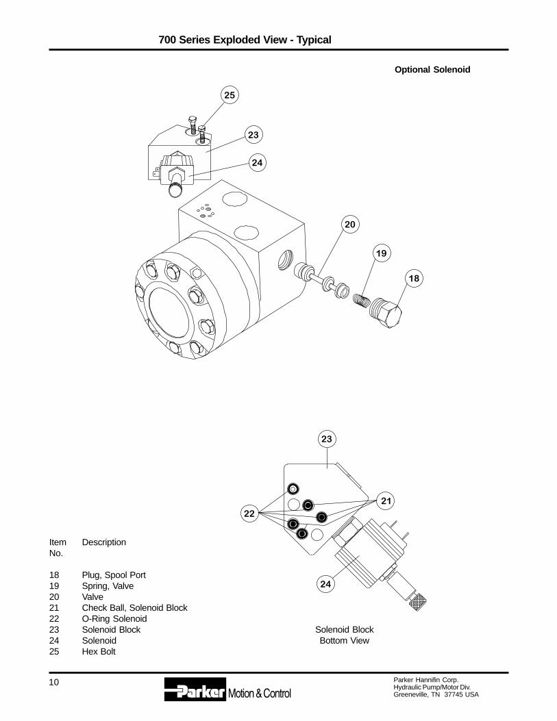
Item DescriptionNo.
18 Plug, Spool Port19 Spring, Valve20 Valve21 Check Ball, Solenoid Block22 O-Ring Solenoid23 Solenoid Block24 Solenoid25 Hex Bolt
700 Series Exploded View - Typical
Optional Solenoid
21
22
23
24

Parker Hannifin Corp.Hydraulic Pump/Motor Div.Greeneville, TN 37745 USA
11
(Preparation Before Disassembly)
• Before you disassemble the motor unit or any of its components read this entiremanual. It provides important information on parts and procedures you will needto know to service the motor.
• Refer to page four for tools and other items required to service the motor andhave them available.
• Thoroughly clean off all outside dirt, especially from around fittings and hoseconnections, before disconnecting and removing the motor. Remove rust orcorrosion from coupling shaft.
• Remove coupling shaft connections and hose fittings and immediately plug portholes and fluid lines.
• Remove the motor from system, drain it of fluid and take it to a clean worksurface.
• Clean and dry the motor before you start to disassemble the unit.
• As you disassemble the motor clean all parts, except seals, in clean petroleumbased solvent, and blow them dry.
WARNING: Since they are flammable, be extremely careful whenusing any solvent. Even a small explosion or fire couldcause injury of death.
WARNING: Wear eye protection and be sure to comply with OHSA orother maximum air pressure requirements.
CAUTION: Never steam or high pressure wash hydrauliccomponents. Do not force or abuse closely fitted parts.
• Keep parts separate to avoid nicks and burrs.
• Discard all seals and seal rings, as they are removed from the motor. Replace allseals, seal rings and any damaged or worn parts with genuine Parker or OEMapproved service parts.
Disassembly and Inspection
Parker Hannifin Corp.Hydraulic Pump/Motor Div.Greeneville, TN 37745 USA
12
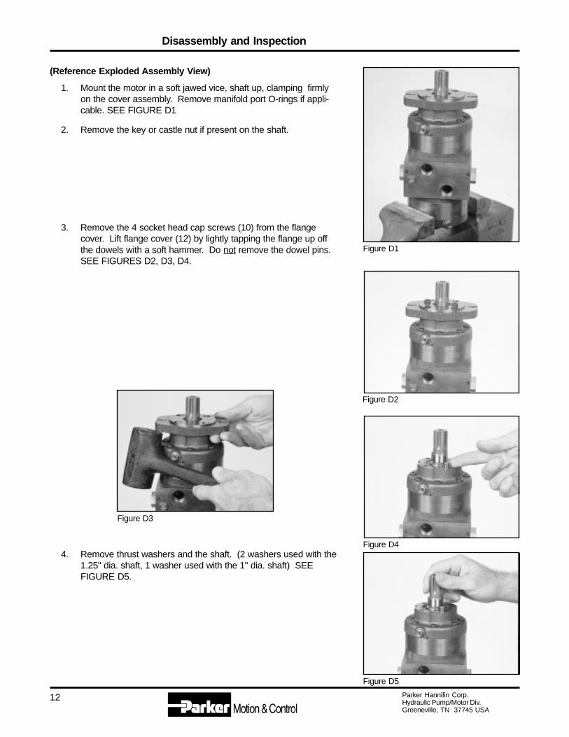
(Reference Exploded Assembly View)
1. Mount the motor in a soft jawed vice, shaft up, clamping firmlyon the cover assembly. Remove manifold port O-rings if appli-cable. SEE FIGURE D1
2. Remove the key or castle nut if present on the shaft.
3. Remove the 4 socket head cap screws (10) from the flangecover. Lift flange cover (12) by lightly tapping the flange up offthe dowels with a soft hammer. Do not remove the dowel pins.SEE FIGURES D2, D3, D4.
4. Remove thrust washers and the shaft. (2 washers used with the1.25" dia. shaft, 1 washer used with the 1" dia. shaft) SEEFIGURE D5.
Figure D5
Figure D3
Figure D4
Figure D2
Figure D1
Disassembly and Inspection

Parker Hannifin Corp.Hydraulic Pump/Motor Div.Greeneville, TN 37745 USA
13
5. Loosen and remove the 8 socket screws (15) to remove thefront bearing housing (16) and the locating ring. Removerollers and check balls. SEE FIGURES D6 & D7.
Caution: The rollers & check balls will fall out so beready to catch them to prevent damage andloss.
Note: The check balls may fall into the bolt holesor into the commutator ports.
6. Separate the locating ring from the front bearing housing (16)by holding the locating ring in hand and tapping the housingwith a soft nosed hammer.
Caution: If placed in a vise, use minimal clampingforce to prevent a permanent out of roundcondition.
7. Remove the outer carefully to prevent rolls from falling orremove rolls with a magnet. SEE FIGURE D8.
8. Remove rolls, inner and valve plate. SEE FIGURES D9 &D10.
Figure D6
Figure D7
Figure D8
Figure D9
Disassembly and Inspection

Parker Hannifin Corp.Hydraulic Pump/Motor Div.Greeneville, TN 37745 USA
14
9. Remove commutator plate assembly (7) and seal (6). SEEFIGURE D11.
10. Turn motor assembly upside down and clamp center block (9) invise. SEE FIGURE D12.
11. Loosen and remove the 8 5/16-24 bolts (1), remove the cover(2), locating ring, check valve balls (quantity 2) (8) and rollers.SEE FIGURES D13 & D14.
CAUTION: The rollers will fall out so be ready to catchthem to prevent damage and loss.
Figure D10
Figure D11
Figure D12
Figure D13
Disassembly and Inspection

Parker Hannifin Corp.Hydraulic Pump/Motor Div.Greeneville, TN 37745 USA
15
Figure D14
Figure D15
Figure D16
Figure D17
12. Remove the outer, rolls, inner and valve plate.SEE FIGURE D15.
13. Lift shaft (6) up a short distance, push the valve plate downand remove the 2 snap ring pieces (5). SEE FIGURE D16.
Note: With the snap ring removed the shaft willfall out of the motor unless, you maintain agrip on the it.
14. Remove valve plate, shaft (6) commutator plate (7) and seal(3). SEE FIGURE D17
Disassembly and Inspection
Parker Hannifin Corp.Hydraulic Pump/Motor Div.Greeneville, TN 37745 USA
16
Figure D18
Figure D19
Figure D20
Figure D21
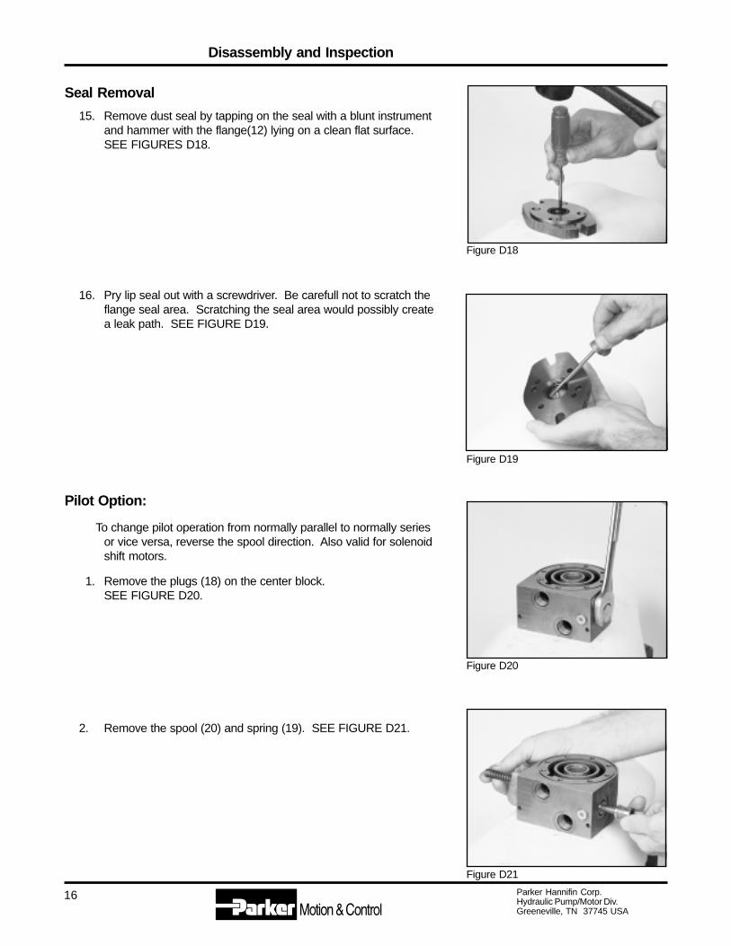
Seal Removal
15. Remove dust seal by tapping on the seal with a blunt instrumentand hammer with the flange(12) lying on a clean flat surface.SEE FIGURES D18.
16. Pry lip seal out with a screwdriver. Be carefull not to scratch theflange seal area. Scratching the seal area would possibly createa leak path. SEE FIGURE D19.
Pilot Option:
To change pilot operation from normally parallel to normally seriesor vice versa, reverse the spool direction. Also valid for solenoidshift motors.
1. Remove the plugs (18) on the center block.SEE FIGURE D20.
2. Remove the spool (20) and spring (19). SEE FIGURE D21.
Disassembly and Inspection

Parker Hannifin Corp.Hydraulic Pump/Motor Div.Greeneville, TN 37745 USA
17
3. Looking at the port surface, install the spool with ...
A) the “double” or "wide" land nearest the “pilot port” fornormally parallel operation. SEE FIGURE 22.
B) the “double” or "wide" land opposite the “pilot port” fornormally series operation. SEE FIGURE 23.
4. The spring is always located on the side, opposite the “pilotport”. SEE FIGURE 21.
THE DISASSEMBLY OF THE MOTOR IS COMPLETED.
PARTS INSPECTION:Inspect the shaft for a smooth polish in the bearing and sealareas.
If scratched, polish with fine emery paper in circumferentialdirection. If pitted, or if scratches are deep, replace shaft andcheck the rest of the motor for scratches, galling, or contamina-tion damage. Replace parts as needed.
If your motor has a thru shaft option and the seals were leaking,the entire cover must be replaced. Thru covers contain noservicable parts.
Figure D22
Figure D23
Disassembly and Inspection

Parker Hannifin Corp.Hydraulic Pump/Motor Div.Greeneville, TN 37745 USA
18
Figure A02
Figure A01
PROCEDURE:
1. Assemble the new dust seal flat edge facing in into the flange(12).
2. Assemble the new shaft seal, and place flat side facing out, overthe shaft (11) to the shoulder. Insert shaft into flange. Tap shaftend with soft hammer to seat seal. SEE FIGURE A01.
NOTE: With 1" Dia. shafts (2970-X); thrust bearing mustnow be pressed into the flange with the copper sidefacing inward.
3. Position the center block (9) so the pilot port or solenoid ports areon your right and lock in the vise. SEE FIGURE A02.
Replace all seals and seal rings with new ones each time you reassemble the motor unit. Lubricate all sealsand seal rings with oil or clean grease before assembly.
NOTE: Individual seals and seal rings as well as a complete seal kit are available. The parts shouldbe available through most OEM parts distributors or Parker distributors. (Contact your localdealer for availability.)
NOTE: Unless otherwise indicated, do not oil or grease parts before assembly.
Wash all parts in clean petroleum-based solvents before assembly. Blow them dry with compressed air.Remove any paint chips from mating surfaces and from port and sealing areas.
WARNING: Since they are flammable, be extremely careful when using any solvent. Even a smallexplosion or fire could cause injury of death.
WARNING: Wear eye protection and be sure to comply with OHSA or other maximum airpressure requirements.
Motor Assembly

Parker Hannifin Corp.Hydraulic Pump/Motor Div.Greeneville, TN 37745 USA
19
Figure A03
Figure A04
Figure A05
Figure A06
4. Place the square cut seal (3) in center block seal gland. SEEFIGURE A03.
5. Place commutator plate (7) on the center block (9) with thesquare ring groove facing up. Align the 8 bolt holes in theplate with the 8 tapped holes in the body. (The holes will alignin only 1 position). Note: Do not dislodge square ring seal (3)while positioning the commutator plate (7). SEE FIGURE A04
6. Insert the internal shaft through the commutator plate andcenter block with the spline snap ring groove “up”. Then placethe counterbored (at the splines) valve plate on the shaft withthe counterbore facing up to accept the snap ring halves (5) inthe next step. SEE FIGURE A05
7. Next put both snap ring halves (5) into the snap ring grooveon the shaft (6). Hold the snap rings in place with pliers whilegently tapping the shaft down, seating the snap rings into thevalve plate counterbore SEE FIGURES A06.
Motor Assembly

Parker Hannifin Corp.Hydraulic Pump/Motor Div.Greeneville, TN 37745 USA
20
Figure A07
Figure A09
Figure A10
8. Place the square cut seal (3) in the commutator plate (7) sealgland. SEE FIGURE A07.
9. Place the inner counterbored side down on the splines so thatthe semicircular roll pockets are between the rotary valve portwindows. Rotate the shaft and align one valve plate windowperpendicular to the flat center block port face. Keep this valve/shaft position to enable proper timing of the motor in step 17. Aproperly timed motor will help smooth out low speed operation( i.e. 180° out of phase). SEE FIGURE A08.
10. Place the outer over the inner and insert the rolls. The rollsshould not block the ports in the valve plate. SEE FIGURE A09Place the check balls (8) on their seats on the commutator plate.(Assembly grease can be used to keep the check balls in placeduring assembly). SEE FIGURE A10.
11. Place the locating ring over the inner with the square oil returngroove up and the check ball counterbores over the check balls.Align the 8 bolt holes with the commutator holes. SEE FIGUREA10.
12. Alternate inserting long and short rollers between the outer andlocating ring to match up with 4 dowels in the cover.
NOTE: The difference between rolls and rollers is thatrolls have square ends and rollers have aradius on the ends.
Figure A08
Motor Assembly
Parker Hannifin Corp.Hydraulic Pump/Motor Div.Greeneville, TN 37745 USA
21
Figure A11
Figure A12
Figure A13
Figure A14
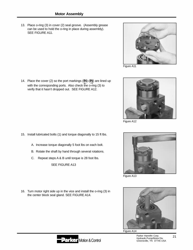
13. Place o-ring (3) in cover (2) seal groove. (Assembly greasecan be used to hold the o-ring in place during assembly).SEE FIGURE A11.
14. Place the cover (2) so the port markings (IN)-(IN) are lined up
with the corresponding ports. Also check the o-ring (3) toverify that it hasn’t dropped out. SEE FIGURE A12.
15. Install lubricated bolts (1) and torque diagonally to 15 ft lbs.
A. Increase torque diagonally 5 foot lbs on each bolt.
B. Rotate the shaft by hand through several rotations.
C. Repeat steps A & B until torque is 28 foot lbs.
SEE FIGURE A13
16. Turn motor right side up in the vice and install the o-ring (3) inthe center block seal gland. SEE FIGURE A14.
Motor Assembly
➞
➞

Parker Hannifin Corp.Hydraulic Pump/Motor Div.Greeneville, TN 37745 USA
22
Figure A15
Figure A16
Figure A17
Figure A18
17. Place the commutator plate on the center block with the squarering groove facing up. Align the 8 bolt holes with the 8 tappedholes in the center block. SEE FIGURE A15
18. With the valve plate windows sharp edge facing the commutatorplate, place the valve plate over the splines of the shaft. Theplate should be positioned one tooth off the opposite end valveplate when viewing valve plate port timing with respect to thecommutator plate. SEE FIGURE A16.
19. Install a o-ring into the grove in the commutator plate. SEEFIGURE A17
20. Place the inner over the splines of the shaft. Position the innerso the semi-circular roll pockets are between the rotary valveport windows. SEE FIGURE A18.
21. Place the outer over the inner and insert the rolls into the innerpockets.
NOTE: The difference between rolls and rollers is thatrolls have square ends and rollers have aradius on the end.
Motor Assembly

Parker Hannifin Corp.Hydraulic Pump/Motor Div.Greeneville, TN 37745 USA
23
Figure A19
Figure A20
Figure A21
Figure A22
WARNING: Do not rotate the locating ring or checkballs will drop into bolt holes.
22. Place the check balls (8) on their seats on the commutatorplate. Place the locating ring section onto the commutatorplate with the check ball counterbored facing downward overthe balls. Align the 8 bolt holes with the commutator holes.Place the rollers in position alternating long and short to matchup with the 4 dowels in the front bearing housing (16). SEEFIGURE A19
23. Install a o-ring (3) into the groove of the front bearing housing(16). Place the front bearing housing w/ o-ring over the shaftand onto the locating ring. Be sure to align the 4 dowels withthe short dowels inside the locating ring and to align the boltholes with the holes in the locating ring. ( bolt hole pattern willonly match one way.) SEE FIGURE A20
24. Insert o-ring seal (13) into the front bearing housing (16). SEEFIGURE A21.
25. Insert shaft (11). Gently tap in with a soft hammer, rotating theshaft if necessary to align the splines. SEE FIGURE A22
Motor Assembly

Parker Hannifin Corp.Hydraulic Pump/Motor Div.Greeneville, TN 37745 USA
24
Figure A23
Figure A24
For the 1.25" dia. shaft;
Place the thrust washer (11A) on the shaft and placethe thrust bearing (11A) on top of the thrust washer. theGrooves on the bearing washer must face towards theshaft seal. SEE FIGURE A23
For the 1" dia. shaft;
There is only one thrust washer and it can be as-sembled either way. The thrust bearing is pressed inthe front bearing housing.
26. Install the 8 lubricated bolts and torque diagonally to 15 ft lbs.
A. Increase torque diagonally 5 foot lbs on each bolt.
B. Rotate the shaft by hand through several rotations.
C. Repeat steps A & B until torque is 30 foot lbs.
27. Place the flange ( ) with 2 dowels ( ) over the shaft and onto thefront bearing housing, align the dowel pins as you install theflange. Lubricate and install the 4 socket head cap screws andtorque to 25 lb ft. SEE FIGURE A24.
Motor Assembly
Parker Hannifin Corp.Hydraulic Pump/Motor Div.Greeneville, TN 37745 USA
25
Figure A25
Figure A26
Figure A27
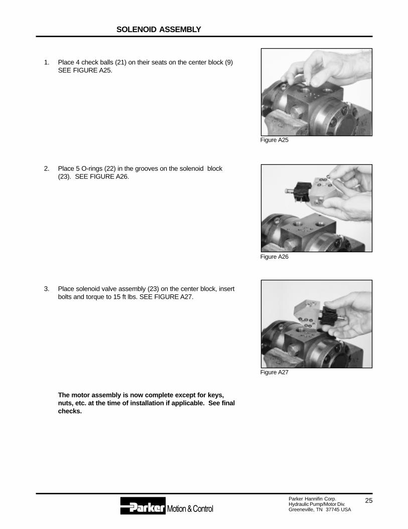
1. Place 4 check balls (21) on their seats on the center block (9)SEE FIGURE A25.
2. Place 5 O-rings (22) in the grooves on the solenoid block(23). SEE FIGURE A26.
3. Place solenoid valve assembly (23) on the center block, insertbolts and torque to 15 ft lbs. SEE FIGURE A27.
The motor assembly is now complete except for keys,nuts, etc. at the time of installation if applicable. See finalchecks.
SOLENOID ASSEMBLY

Parker Hannifin Corp.Hydraulic Pump/Motor Div.Greeneville, TN 37745 USA
26
Final Checks
• Pressurize the motor with 100 p.s.i. dry air or nitrogen and submerge in solvent to check for external leaks.
• Port with → cast adjacent to the port indicates shaft rotation.
• Check operation of the motor with a test stand.
Hydraulic Fluid
Keep the hydraulic system filled with one of the following:
• Hydraulic fluid as recommended by equipment manufacturer, with viscosity no less than 50 SSU.
CAUTION: Do not mix oil types. Any mixture, or a non approved oil, could deteriorate theseals. Maintain the proper fluid level in the reservoir. When changing fluid,completely drain old oil from the system. It is suggested also that you flush thesystem with clean oil, especially if there was a major hydraulic component failure.In addition run the system with no load for a period of time to allow the filters toclean up the oil. Then change the filters before returning the machine to service.
Filtration
• Recommended filtration: Beta 25 ratio of at least 2.
Oil Temperature• Maximum operating temperature 180º
General
IN

Parker Hannifin Corp.Hydraulic Pump/Motor Div.Greeneville, TN 37745 USA
27
• Adjust fluid level in reservoir as necessary.
• Encourage all operators to report any malfunction or accident that may have damaged the hydraulic system orcomponent.
• Do not attempt to weld any broken motor component. Replace the component with original equipment only.
• Do not cold straighten, or bend any motor part.
• Prevent dirt or other foreign matter from entering the hydraulic system. Clean the area around the filler capsbefore checking oil level.
• Investigate and correct any external leak in the hydraulic system, no matter how minor.
• Comply with manufacturer’s specifications for cleaning or replacing the filter.
CAUTION: Do not strike or drop the motor on the shaft end. This will cause internal damage.
CAUTION: Do not weld, braze, solder, or in any way alter any motor component.
CAUTION: Maximum operating pressure must not exceed recommended motor pressurecapacity.
CAUTION: Always carefully inspect any system component that may have been struck ordamaged during operation or in an accident. Replace any component that isdamaged or that is questionable.
CAUTION: Do not force any coupling onto the motor coupling shaft as this could damage theunit internally.
Parker Hannifin Corp. extends close technical cooperation and assistance. If problems occur which youcannot solve, please contact our Parker Technical Service Representative or local Parker Distributor. See theback cover of this manual for our address, phone and fax numbers.
Maintenance Tips