low voltage systems subtitle - abb group —seismic qualification circuit breaker ... (1120 mm)...
TRANSCRIPT

© BU 3101 Low Voltage SystemsMay 5, 2009| Slide 1
Low Voltage SystemsMaxSB - Low Voltage Switchboard
BU 3101 Low Voltage Systems, March 2009

© BU 3101 Low Voltage Systems April 8, 2011 | Slide 2
MaxSB Product Overview
Description Value
Rated Main bus current 1600A, 2000A, 3000A,
3200A, 4000A, 5000A
Group Mounted Vertical bus 800A, 1500A, 2250A
Distribution vertical bus 1000A-5000A
Rated tested maximum
voltage
254Vac, 508Vac, 635Vac
Rated voltage 240Vac, 480Vac, 600Vac
Phases 3 phase 3 wire, 3 phase 4
wire
Neutral 100% rated
Frequency 50/60 Hz
Short circuit current 480V 65kA, 100kA
Short circuit current 600V 50kA
Service Entrance Yes (Optional)
Enclosure NEMA 1

© BU 3101 Low Voltage Systems April 8, 2011 | Slide 3
MaxSB Standards
SWITCHBOARD
UL 891 — Low Voltage Switchboards
CSA C22.2 No. 244-05 — Canadian Standards Association
ANCE NMX-J-1182/2 — Association of Standardization and Certification
ANCE-2006
IEEE-STD-693-2005 — Seismic Qualification
CIRCUIT BREAKER
ANSI C37.13 – LV AC Power Circuit Breakers Used in Equipment
ANSI C37.16 – Preferred Rating, Related Requirement, Application
Recommendations For LV Power Circuit Breakers and AC Power
Circuit Protectors
ANSI C37.50 – Testing of Low Voltage AC Power Circuit Breakers
UL 1066 – Low Voltage Power Circuit Breakers
UL489 – Standard for Molded-Case Circuit. Breakers and Circuit Breaker
Enclosures
CSA 22.2 – Canadian standard for enclosures
© BU 3101 Low Voltage Systems April 8, 2011 | Slide 4
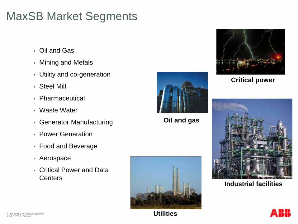
MaxSB Market Segments
Oil and Gas
Mining and Metals
Utility and co-generation
Steel Mill
Pharmaceutical
Waste Water
Generator Manufacturing
Power Generation
Food and Beverage
Aerospace
Critical Power and Data
Centers
Critical power
Industrial facilities
Oil and gas
Utilities

© BU 3101 Low Voltage Systems April 8, 2011 | Slide 5
MaxSB Offerings
Hinged door, large wire
ways save time and money
in field wiring.
Plated copper bus used in
all three phases and
neutral.
Copper ground bus extends
full width of switchboard.
Horizontal bus up to 5000A
Vertical bus up to 2250A

© BU 3101 Low Voltage Systems April 8, 2011 | Slide 6
MaxSB Structure
Standard Textured Paint Finish RAL7035
Frame is made of Turati ArTu-K made of zinc coated steel of thickness 1.5 mm
Frame is reinforced with #12 ga galvanized supports
Frame is secured on corners by a three way aluminum joint
Shipping base is four inches high #12 ga galvanized steel
All switchboards are shipped on wooden pallets
Maximum shipping split is 78‖
Four inch base is standard
92‖ Height
Lifting eyes on roof

© BU 3101 Low Voltage Systems April 8, 2011 | Slide 7
MaxSB Dimensions - Widths

© BU 3101 Low Voltage Systems April 8, 2011 | Slide 8
MaxSB Dimensions - Depths

© BU 3101 Low Voltage Systems April 8, 2011 | Slide 9
MaxSB Covers and Doors
All doors and covers are
painted RAL 7035
Emax breaker doors are #14 ga
thickness and are secured by screws
Side panels and rear panels are
#16 ga galvanized steel
Top panel is #14 ga steel
Group mounted door and breaker
covers are #16 ga steel and is
locked by door handle

© BU 3101 Low Voltage Systems April 8, 2011 | Slide 10
MaxSB Layouts – Main and Tie Sections
Dimensions Line/Load Lug Information
Amperage (A)
Frame
Size Width Depth Quantity
(per phase)
Size (kcmil)
Mechanical
800 2
1200 3
1600 4
2000 5
2500
E3 28.3‖
(720mm) 33‖
(840 mm)
6
3000 8
3200 E4
37‖ (940 mm)
33‖ (840 mm) 8
4000 10
5000 E6
44‖ (1120 mm)
41‖ (1037 mm) 12
#2-600

© BU 3101 Low Voltage Systems April 8, 2011 | Slide 11
MaxSB Layouts – Emax Feeder Sections
The MaxSB can provide stacked
feeder sections up to 2000A
using fixed or drawout type Emax
power circuit breakers (UL1066).
Each circuit breaker is located
behind a hinged door secured by
screws.
The MaxSB utilizes only the E3
frame size.
Dimensions Line/Load Lug Information
Amperage (A)
Frame
Size Width Depth Quantity
(per phase)
Size (kcmil)
Mechanical
800 2
1200 3
1600 4
2000
E3 28.3‖
(720mm) 33‖
(840 mm)
5
#2-600

© BU 3101 Low Voltage Systems April 8, 2011 | Slide 12
MaxSB Layouts – Group Mounted Sections
Breaker are mounted by bus
straps
Bus straps are covered with
electrical tape
holes on vertical bus allow
for mounting of breakers at
different location
Incoming can be main lug or
single main for single group
mounted sections
3P4W require depth of 33‖
(840mm)
Single group mounted can be
15‖ (385 mm) deep
3000A requires an incoming pull
section

© BU 3101 Low Voltage Systems April 8, 2011 | Slide 13
MaxSB Layouts – Group Mounted Sections
For 2500A and 3000A sections
an incoming pull section is
required
Only uses Tmax breakers

© BU 3101 Low Voltage Systems April 8, 2011 | Slide 14
MaxSB Layouts
Pull Sections
28.3" 37"
92"
Instrument
Compartment
Instrument
Compartment
40"
Instrument
Compartment

© BU 3101 Low Voltage Systems April 8, 2011 | Slide 15
MaxSB Horizontal Bus Design
Horizontal bus ratings:
1600A, 2000A, 3000A,
3200A, 4000A, and 5000A
Short Circuit Current: 100
kA (3 Cycle Rating)
Silver-plated standard with
option for tin-plated
Location is top, bottom, or
middle depending on
incoming and application
© BU 3101 Low Voltage Systems April 8, 2011 | Slide 16
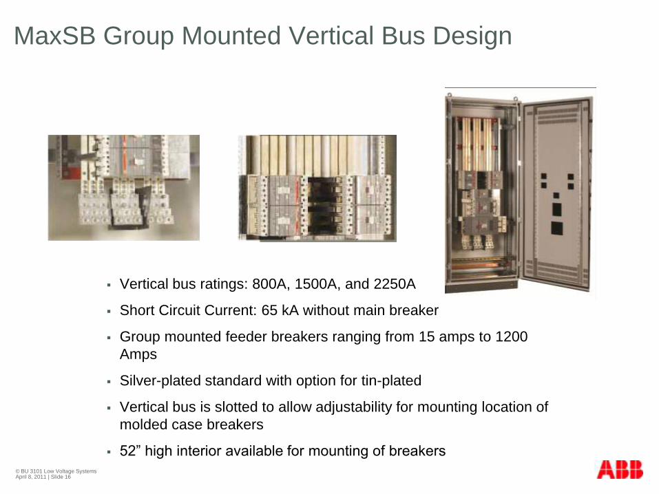
MaxSB Group Mounted Vertical Bus Design
Vertical bus ratings: 800A, 1500A, and 2250A
Short Circuit Current: 65 kA without main breaker
Group mounted feeder breakers ranging from 15 amps to 1200
Amps
Silver-plated standard with option for tin-plated
Vertical bus is slotted to allow adjustability for mounting location of
molded case breakers
52‖ high interior available for mounting of breakers

© BU 3101 Low Voltage Systems April 8, 2011 | Slide 17
MaxSB Group Mounted Vertical Bus Design
1P 1P 2.06 in T1 100 Amp
2/3 Pole 2/3 Pole 4.13 in T2 100 Amp
2/3 Pole 2/3 Pole 4.13 in T3 225 Amp
2/3 Pole 2/3 Pole 4.13 in TS3 225 Amp
2/3 Pole 4.13 in T4 250 Amp
3 Pole 5.51 in T5 400 Amp
3 Pole 5.61 in T4/T5 400 Dbl
2/3 Pole 8.27 inT6 800 Amp
T7 1200 Amp
36" Wide Structure
52‖ o
f availa
ble
space

© BU 3101 Low Voltage Systems April 8, 2011 | Slide 18
MaxSB Group Mounted – Sizing Section
Example:
2 - T2 40A
1 – T6 600A
2 –T4 200A
2 – T5 400A
Total amperage sum = 1888A
Total number of breakers = 7, reduction percentage = 60%
Therefore total available current = 1888 X .6 = 1128A, therefore 1250A vertical
bus is required

© BU 3101 Low Voltage Systems April 8, 2011 | Slide 19
MaxSB Ground Bus Design
Single group mounted sections: ¼ x 2‖ bare copper
All other types of sections: ¼ X 4‖ bare copper
One TA600-NS lug per section is provided as standard,
others may be added upon request

© BU 3101 Low Voltage Systems April 8, 2011 | Slide 20
MaxSB Barriers
Instrument mounting panels
are used for mounting electrical
equipment and as barriers to
isolate electrical components
from the main bus when
accessing through the front.
Optional glastic or steel
barriers are available between
each section to segregate each
section completely.
When service entrance is
required, the MaxSB will
incorporate all appropriate
service entrance barriers.

© BU 3101 Low Voltage Systems April 8, 2011 | Slide 21
MaxSB Emax Power Circuit Breakers
800 - 5000 Amps
Frame Sizes: E3, E4, and E6
Fixed/Drawout
Electronic Trip
Compact Size
High Interrupting Rating
Extremely High Mechanical & Electrical life

© BU 3101 Low Voltage Systems April 8, 2011 | Slide 22
MaxSB Emax Power Circuit Breaker
PR121
Protection Features Only
PR122
Protection Features
LCD Display
Current Measurement
Contact Wear
Communications option
PR123
PR122 Features
Harmonic Measurements
Communications option
There are three types of trip units available

© BU 3101 Low Voltage Systems April 8, 2011 | Slide 23
MaxSB Emax Power Circuit Breaker
PR121P Trip Unit
LED Display
LSIG Protection
Wireless communication by means of the BT030 adapter unit
plugged in the front

© BU 3101 Low Voltage Systems April 8, 2011 | Slide 24
MaxSB Emax Power Circuit Breaker
PR122P Trip Unit
LCD Display
LSIG Protection
Phase unbalance protection U
Zone discrimination for S and G protection
Self-diagnosis
Data Logging
Modbus Communication
Measurement function

© BU 3101 Low Voltage Systems April 8, 2011 | Slide 25
MaxSB Emax Power Circuit Breaker
PR123P Trip Unit
LCD Display
LSIG Protection
Double selective S and G function
Phase unbalance protection U
Zone discrimination for S and G protection
Self-diagnosis
Data Logging
Modbus Communication
Measurement function
Harmonic calculation up to the 40th harmonic

© BU 3101 Low Voltage Systems April 8, 2011 | Slide 26
MaxSB Emax Power Circuit Breaker
There are multiple modules that can be incorporated in the PR122 and PR123 trip units
PR120/V – Measurement Module
Provides voltage, data logging, power, power factor, frequency, energy, UV, OV, RV, Reverse power protection, and frequency protection
PR120/K – Electrical Signaling Module
Provides remote signaling of alarms and trips of breaker and can be provided with a digital input enabling external trip, activation of alternate set of parameter, trip reset, and reset of PR120/K power relays
PR120/D-M – Modbus Communication Module
Provides Modbus Communication to PR122 and PR123 trip unit
PR021/K – Signaling Unit
Converts digital signals by PR121, PR122, and PR123 into electrical signals. (overload pre-alarm, timing and tripping of protections, overtemperature, trip unit tripped, dialogue fault on serial line, and phase unbalance)

© BU 3101 Low Voltage Systems April 8, 2011 | Slide 27
MaxSB Emax Power Circuit Breaker
Breaker Electrical Contacts
Aux Contacts: 4, 10, and
15
TOC Contacts: 5 and 10
Sliding Contacts
Contacts for signaling
closing springs charged
Contacts for signaling
undervoltage release

© BU 3101 Low Voltage Systems April 8, 2011 | Slide 28
MaxSB Emax Power Circuit Breaker
Breaker Electrical Accessories
Shunt Trip
Second Shunt Trip
Charging Motor
Bell Alarm
Undervoltage Release

© BU 3101 Low Voltage Systems April 8, 2011 | Slide 29
MaxSB Emax Power Circuit Breaker
Breaker Mechanical Accessories
Operation Counter
Circuit breaker lock in
racked-in/test
isolated/racked-out position
Key locking provisions
Padlock provisions
Button Guard

© BU 3101 Low Voltage Systems April 8, 2011 | Slide 30
MaxSB Tmax Molded Case Breakers
Frame sizes from T1 -100A to T7 - 1200A
Thermal Magnetic or Electronic Trip Units
Fixed Mounted
Double insulation provided between live power parts and the front of
the apparatus preventing any risk of contact
Interrupting rating up 100kA

© BU 3101 Low Voltage Systems April 8, 2011 | Slide 31
MaxSB Tmax Molded Case Breakers
Four types of Trip Units for T1- T6
Thermal Magnetic
PR221DS LI
PR222DS/P LSI
PR222DS/PD-A LSIG
Four types of Trip Units for T7
PR231/P LI
PR232/P LSI
PR331/P LSIG
PR332/P LI, LSI, LSIG

© BU 3101 Low Voltage Systems April 8, 2011 | Slide 32
MaxSB Tmax Interrupting Ratings

© BU 3101 Low Voltage Systems April 8, 2011 | Slide 33
MaxSB Tmax Molded Case Breakers
Multiple Common
Accessories between each
frame
Undervoltage Release
Shunt Trip
Closing Coil
Aux Contacts
Charging Motor

© BU 3101 Low Voltage Systems April 8, 2011 | Slide 34
MaxSB Instrumentation and Metering
Door mounted lights, meters and control
ABB Indicating Lights
Volt, amp, and watt meters
Electroswitch Series 20 and 24 control
switch
Multifunction Metering
Electro Industries
Others (optional)
Relays
ABB (provided standard when
required)
Others (Optional)
Surge Protectors
APT or ABB TVSS (Standard)
Others (Optional)

© BU 3101 Low Voltage Systems April 8, 2011 | Slide 35
MaxSB Accessories
Lift Truck for removing of
Emax power breakers
Breaker test cabinets for
testing Emax breakers
PR010/T portable test unit
for all breakers

© BU 3101 Low Voltage Systems April 8, 2011 | Slide 36
MaxSB Applications
Main-Tie-Main transfer schemes
(open and close)
ABB standard only
Kirk Key Interlock
© BU 3101 Low Voltage Systems April 8, 2011 | Slide 37
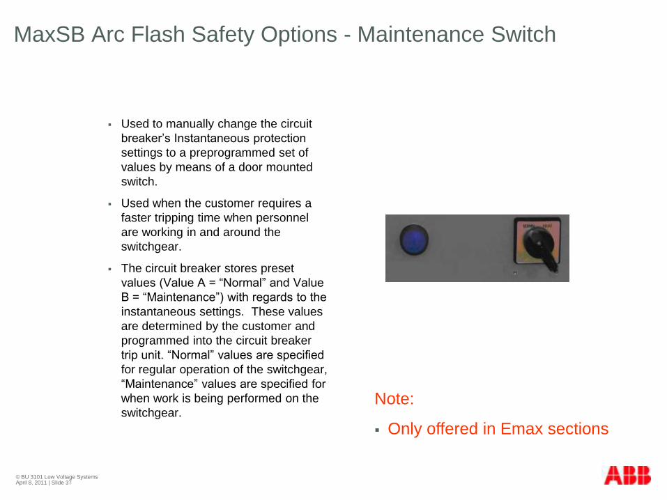
MaxSB Arc Flash Safety Options - Maintenance Switch
Used to manually change the circuit
breaker’s Instantaneous protection
settings to a preprogrammed set of
values by means of a door mounted
switch.
Used when the customer requires a
faster tripping time when personnel
are working in and around the
switchgear.
The circuit breaker stores preset
values (Value A = ―Normal‖ and Value
B = ―Maintenance‖) with regards to the
instantaneous settings. These values
are determined by the customer and
programmed into the circuit breaker
trip unit. ―Normal‖ values are specified
for regular operation of the switchgear,
―Maintenance‖ values are specified for
when work is being performed on the
switchgear. Note:
Only offered in Emax sections
© BU 3101 Low Voltage Systems April 8, 2011 | Slide 38
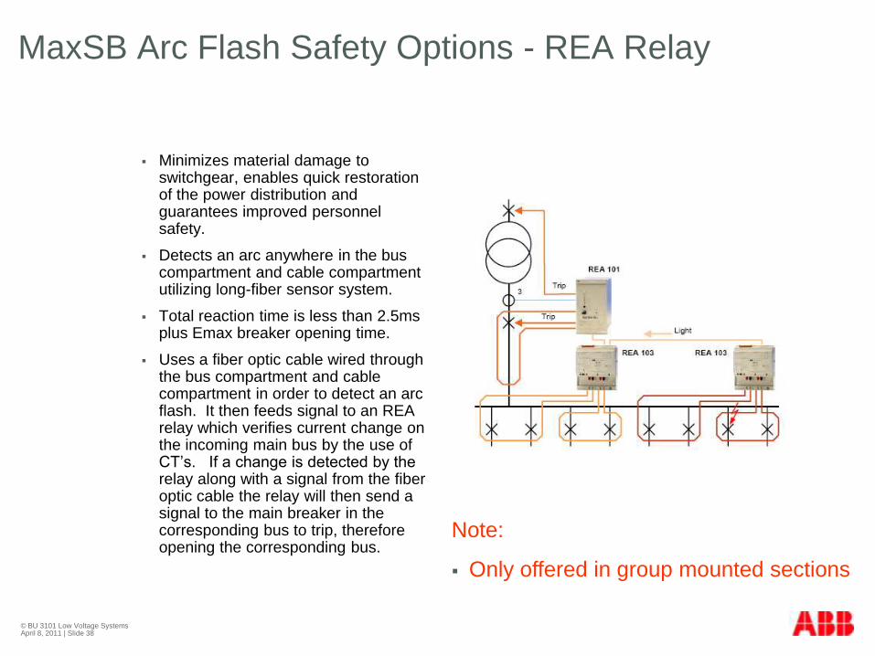
MaxSB Arc Flash Safety Options - REA Relay
Minimizes material damage to switchgear, enables quick restoration of the power distribution and guarantees improved personnel safety.
Detects an arc anywhere in the bus compartment and cable compartment utilizing long-fiber sensor system.
Total reaction time is less than 2.5ms plus Emax breaker opening time.
Uses a fiber optic cable wired through the bus compartment and cable compartment in order to detect an arc flash. It then feeds signal to an REA relay which verifies current change on the incoming main bus by the use of CT’s. If a change is detected by the relay along with a signal from the fiber optic cable the relay will then send a signal to the main breaker in the corresponding bus to trip, therefore opening the corresponding bus.
Note:
Only offered in group mounted sections

© BU 3101 Low Voltage Systems April 8, 2011 | Slide 39
MaxSB Features and Benefits
Strong frame construction isolates
bus and breaker assemblies from
enclosure ―skin‖.
Unique bus layout delivers the
freedom to locate feeder breakers
independent of any hole pattern.
Optional barriers for increased
personnel protection
Hinged door, large wire ways save time
and money in field wiring.
Standard connections to a full range
of ABB products
Modbus Communication
Transfer Schemes

© BU 3101 Low Voltage Systems April 8, 2011 | Slide 40
MaxSB Competitive Aspects
Competitive Footprint
Stability and strong structure
Emax breaker
Trip Units PR121P, PR122P, and PR123P
Safety Features
Tmax breakers
Multiple frame sizes with common accessories
Communication Capabilities (SCADA, Modbus,
Ethernet, etc.)

Visit us at www.abb.com/us