ltc 8100, ltc 8200, ltc 8300 series - bosch security and...
TRANSCRIPT

Instruction Manual
EN AllegiantMicroprocessor-basedSwitcher/ControlSystems
LTC 8100, LTC 8200, LTC 8300 Series

LTC 8100, LTC 8200, LTC 8300 Series | Instruction Manual | Important Safeguards EN | 2
Bosch Security Systems | December 8, 2004
Important Safeguards
1. Read, Follow, and Retain Instructions - All safetyand operating instructions should be read andfollowed before operating the unit. Retain instructionsfor future reference.
2. Heed Warnings – Adhere to all warnings on the unitand in the operating instructions.
3. Attachments - Attachments not recommended bythe product manufacturer should not be used, as theymay cause hazards.
4. Installation Cautions - Do not place this unit on anunstable stand, tripod, bracket, or mount. The unitmay fall, causing serious injury to a person andserious damage to the unit. Use only manufacturer-recommended accessories, or those sold with theproduct. Mount the unit per the manufacturer'sinstructions. Appliance and cart combination shouldbe moved with care. Quick stops, excessive force, oruneven surfaces may cause the appliance and cartcombination to overturn.
5. Cleaning - Unplug the unit from the outlet beforecleaning. Follow any instructions provided with theunit. Generally, using a damp cloth for cleaning issufficient. Do not use liquid cleaners or aerosolcleaners.
6. Servicing - Do not attempt to service this unityourself. Opening or removing covers may exposeyou to dangerous voltage or other hazards. Refer allservicing to qualified service personnel.
7. Damage Requiring Service - Unplug the unit fromthe main AC power source and refer servicing toqualified service personnel under the followingconditions:• When the power supply cord or plug is damaged.• If liquid has been spilled or an object has fallen
into the unit.• If the unit has been exposed to water and/or
inclement weather (rain, snow, etc.).• If the unit does not operate normally, when
following the operating instructions. Adjust onlythose controls specified in the operatinginstructions. Improper adjustment of other controlsmay result in damage, and require extensive workby a qualified technician to restore the unit tonormal operation.
• If the unit has been dropped or the cabinetdamaged.
• If the unit exhibits a distinct change inperformance, this indicates that service is needed.
8. Replacement Parts - When replacement parts arerequired, the service technician should usereplacement parts specified by the manufacturer, orthat have the same characteristics as the original part.Unauthorized substitutions may result in fire,electrical shock, or other hazards.
9. Safety Check - Upon completion of servicing orrepairs to the unit, ask the service technician toperform safety checks to ensure proper operatingcondition.
10. Power Sources - Operate the unit only from the typeof power source indicated on the label. If unsure ofthe type of power supply to use, contact your dealeror local power company. • For units intended to operate from battery power,
refer to the operating instructions. • For units intended to operate with External Power
Supplies, use only the recommended approvedpower supplies.
• For units intended to operate with a limited powersource, this power source must comply withEN60950. Substitutions may damage the unit orcause fire or shock.
• For units intended to operate at 24VAC, normalinput voltage is 24VAC. Voltage applied to theunit's power input should not exceed 30VAC. User-supplied wiring, from the 24VAC supply tounit, must be in compliance with electrical codes(Class 2 power levels). Do not ground the 24VACsupply at the terminals or at the unit's powersupply terminals.
11. Coax Grounding - If an outside cable system isconnected to the unit, ensure that the cable system isgrounded. U.S.A. models only--Section 810 of theNational Electrical Code, ANSI/NFPA No.70,provides information regarding proper grounding ofthe mount and supporting structure, grounding of thecoax to a discharge unit, size of groundingconductors, location of discharge unit, connection togrounding electrodes, and requirements for thegrounding electrode.
12. Grounding or Polarization - This unit may beequipped with a polarized alternating current lineplug (a plug with one blade wider than the other).This safety feature allows the plug to fit into thepower outlet in only one way. If unable to insert theplug fully into the outlet, try reversing the plug. If theplug still fails to fit, contact an electrician to arrangereplacement of the obsolete outlet. Do not defeat thesafety purpose of the polarized plug.Alternately, this unit may be equipped with a 3-wire grounding plug (a plug with a third pin, forgrounding). This safety feature allows the plug to fitinto a grounding power outlet only. If unable to insertthe plug into the outlet, contact an electrician toarrange replacement of the obsolete outlet. Do notdefeat the safety purpose of the grounding plug.
13. Lightning - For added protection during a lightningstorm, or when this unit is left unattended andunused for long periods of time, unplug the unit fromthe wall outlet and disconnect the cable system. Thiswill prevent damage to the unit due to lightning andpower line surges.
LTC 8100, LTC 8200, LTC 8300 Series | Instruction Manual | Safety Precautions EN | 3
Bosch Security Systems | December 8, 2004
For Indoor Product1. Water and Moisture - Do not use this unit near
water - for example, in a wet basement, in anunprotected outdoor installation, or in any areaclassified as a wet location.
2. Object and Liquid Entry - Never push objects ofany kind into this unit through openings, as theymay touch dangerous voltage points or short outparts that could result in a fire or electrical shock.Never spill liquid of any kind on the unit.
3. Power Cord and Power Cord Protection - Forunits intended to operate with 230VAC, 50Hz,the input and output power cord must complywith the latest versions of IEC Publication 227 orIEC Publication 245. Power supply cords should be routed so they arenot likely to be walked on or pinched. Payparticular attention to location of cords and plugs,convenience receptacles, and the point of exitfrom the appliance.
4. Overloading - Do not overload outlets andextension cords; this can result in a risk of fire orelectrical shock.
For Outdoor ProductPower Lines - An outdoor system should not belocated in the vicinity of overhead power lines,electric lights, or power circuits, or where it maycontact such power lines or circuits. Wheninstalling an outdoor system, extreme care shouldbe taken to keep from touching power lines orcircuits, as this contact might be fatal. U.S.A.models only - refer to the National ElectricalCode Article 820 regarding installation of CATVsystems.
For Rack-mount Product1. Ventilation - This unit should not be placed in a
built-in installation or rack, unless properventilation is provided, or the manufacturer’sinstructions have been adhered to. Theequipment must not exceed its maximumoperating temperature requirements.
2. Mechanical Loading - Mounting of theequipment in a rack shall be such that ahazardous condition is not achieved due touneven mechanical loading.
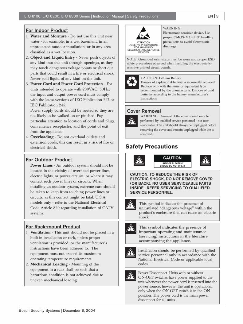
WARNING: Electrostatic-sensitive device. Useproper CMOS/MOSFET handlingprecautions to avoid electrostatic discharge.
NOTE: Grounded wrist straps must be worn and proper ESDsafety precautions observed when handling the electrostatic-sensitive printed circuit boards.
ATTENTIONOBSERVE PRECAUTIONS
FOR HANDLING ELECTROSTATIC SENSITIVE
DEVICES
CAUTION: Lithium Battery Danger of explosion if battery is incorrectly replaced.Replace only with the same or equivalent typerecommended by the manufacturer. Dispose of usedbatteries according to the battery manufacturer’sinstructions.
Cover RemovalWARNING: Removal of the cover should only be performed by qualified service personnel - not user serviceable. The unit should always be unplugged beforeremoving the cover and remain unplugged while the isremoved.
Safety Precautions
Installation should be performed by qualifiedservice personnel only in accordance with theNational Electrical Code or applicable localcodes.
Power Disconnect. Units with or without ON-OFF switches have power supplied to theunit whenever the power cord is inserted into thepower source; however, the unit is operationalonly when the ON-OFF switch is in the ONposition. The power cord is the main powerdisconnect for all units.
CAUTION: TO REDUCE THE RISK OFELECTRIC SHOCK, DO NOT REMOVE COVER(OR BACK). NO USER SERVICEABLE PARTSINSIDE. REFER SERVICING TO QUALIFIEDSERVICE PERSONNEL.
This symbol indicates the presence ofuninsulated “dangerous voltage” within theproduct’s enclosure that can cause an electricshock.
This symbol indicates the presence ofimportant operating and maintenance(servicing) instructions in the literatureaccompanying the appliance.

LTC 8100, LTC 8200, LTC 8300 Series | Instruction Manual | FCC & ICES Information EN | 4
Bosch Security Systems | December 8, 2004
Sicherheitshinweise
Achtung! Die Installation sollte nur von qualifiziertemKundendienstpersonal gemäß jeweils zutreffenderElektrovorschriften ausgeführt werden.
Unterbrechung des Netzanschlusses. Geräte mit oder ohneNetzschalter haben Spannung am Gerät anliegen, sobald derNetzstecker in die Steckdose gesteckt wird. Das Gerät ist jedochnur betriebsbereit, wenn der Netzschalter (EIN/AUS) auf EINsteht. Wenn das Netzkabel aus der Steckdose gezogen wird, istdie Spannungszuführung zum Gerät vollkommen unterbrochen.
VORSICHT: UM EINEN ELEKTRISCHEN SCHLAG ZU
VERMEIDEN, IST DIE ABDECKUNG (ODER RÜCKSEITE) NICHT
ZU ENTFERNEN. ES BEFINDEN SICH KEINE TEILE IN DIESEM
BEREICH, DIE VOM BENUTZER GEWARTET WERDEN
KÖNNEN. LASSEN SIE WARTUNGSARBEITEN NUR VON
QUALIFIZIERTEM WARTUNGSPERSONAL AUSFÜHREN.
Das Symbol macht auf nicht isolierte „gefährliche Spannung"im Gehäuse aufmerksam. Dies kann zu einem elektrischenSchlag führen.
Der Benutzer sollte sich ausführlich über Anweisungen fürdie Bedienung und Instandhaltung (Wartung) in denbegleitenden Unterlagen informieren.
Precauciones de Seguridad
Atención: la instalación la debe realizar únicamente personalcualificado de conformidad con el National Electric Code o lasnormas aplicables en su país.
Desconexión de la alimentación. Las unidades con o sininterruptores de encendido/apagado reciben alimentacióneléctrica siempre que el cable de alimentación esté conectado ala fuente de alimentación. Sin embargo, la unidad sólo funcionacuando el interruptor está en la posición de encendido. El cablede alimentación es la principal fuente de desconexión de todaslas unidades.
PRECAUCIÓN: PARA DISMINUIR EL RIESGO DE DESCARGAELÉCTRICA, NO RETIRE LA CUBIERTA (NI LA PARTEPOSTERIOR). NO EXISTEN PIEZAS DE RECAMBIO EN ELINTERIOR DEL EQUIPO. EL PERSONAL DE SERVICIOCUALIFICADO SE ENCARGA DE REALIZAR LASREPARACIONES.
Este símbolo indica que existen puntos de tensión peligrosossin aislamiento dentro de la cubierta de la unidad. Estospuntos pueden constituir un riesgo de descarga eléctrica.
El usuario debe consultar las instrucciones de funcionamiento ymantenimiento (reparación) en la documentación que sesuministra con el aparato.
FCC & ICES INFORMATION(U.S.A. and Canadian Models Only)This device complies with part 15 of the FCC Rules. Operation issubject to the following two conditions:
(1) This device may not cause harmful interference, and(2) This device must accept any interference received,
including interference that may cause undesiredoperation.
NOTE: This equipment has been tested and found to complywith the limits for a Class B digital device, pursuant to Part 15 ofthe FCC Rules and ICES-003 of Industry Canada. These limitsare designed to provide reasonable protection against harmfulinterference when the equipment is operated in a residentialinstallation. This equipment generates, uses and can radiate radiofrequency energy, and if not installed and used in accordancewith the instructions, may cause harmful interference to radiocommunications. However, there is no guarantee that interferencewill not occur in a particular installation. If this equipment doescause harmful interference to radio or television reception, whichcan be determined by turning the equipment off and on, the useris encouraged to try to correct the interference by one or more of the following measures:
• Reorient or relocate the receiving antenna.• Increase the separation between the equipment and receiver.• Connect the equipment into an outlet on a circuit different
from that to which the receiver is connected.• Consult the dealer, or an experienced radio/TV technician for
help.Intentional or unintentional changes or modifications, notexpressly approved by the party responsible for compliance, shallnot be made. Any such changes or modifications could void theuser’s authority to operate the equipment.The user may find the following booklet, prepared by the FederalCommunications Commission, helpful: How to Identify andResolve Radio-TV Interference Problems. This booklet isavailable from the U.S. Government Printing Office, Washington,DC 20402, Stock No. 004-000-00345-4.
Sécurité
Attention : l'installation doit exclusivement être réalisée par dupersonnel qualifié, conformément au code national d'électricitéaméricain (NEC) ou au code d'électricité local en vigueur.
Coupure de l'alimentation. Qu'ils soient pourvus ou non d'uncommutateur ON/OFF, tous les appareils reçoivent de l'énergie unefois le cordon branché sur la source d'alimentation. Toutefois,l'appareil ne fonctionne réellement que lorsque le commutateur est réglé sur ON. Le débranchement du cordond'alimentation permet de couper l'alimentation des appareils.
ATTENTION : POUR ÉVITER TOUT RISQUE D'ÉLECTROCUTION,
N'ESSAYEZ PAS DE RETIRER LE CAPOT (OU LE PANNEAU
ARRIÈRE). CET APPAREIL NE CONTIENT AUCUN COMPOSANT
SUSCEPTIBLE D'ÊTRE RÉPARÉ PAR L'UTILISATEUR. CONFIEZ
LA RÉPARATION DE L'APPAREIL À DU PERSONNEL QUALIFIÉ.
Ce symbole signale que le produit renferme une « tensionpotentiellement dangereuse » non isolée susceptible deprovoquer une électrocution.
Ce symbole invite l'utilisateur à consulter les instructionsd'utilisation et d'entretien (dépannage) reprises dans ladocumentation qui accompagne l'appareil.

LTC 8100, LTC 8200, LTC 8300 Series | Instruction Manual | Safety Precautions EN | 5
Bosch Security Systems | December 8, 2004
Veiligheidsmaatregelen
Attentie: het apparaat mag alleen door gekwalificeerd personeelworden geïnstalleerd. De installatie dient in overeenstemmingmet de nationale elektrische richtlijnen of de van toepassingzijnde lokale richtlijnen te worden uitgevoerd.
Spanning uitschakelen. Apparatuur met of zonder aan-uitschakelaar staat onder spanning zolang de stekker isaangesloten op de wandcontactdoos. De apparatuur is uitsluitendin werking als de aan-uitschakelaar aan staat. Het netsnoer is de"hoofdschakelaar" voor alle apparatuur.
VOORZICHTIG: OPEN DE BEHUIZING OF DE ACHTERKANTVAN HET APPARAAT NIET. ZO VERMINDERT U HET RISICOOP ELEKTRISCHE SCHOKKEN. IN HET APPARAATBEVINDEN ZICH GEEN ONDERDELEN DIE U ZELF KUNTREPAREREN. LAAT SERVICE EN ONDERHOUD UITVOERENDOOR GEKWALIFICEERD PERSONEEL.
Dit symbool geeft aan dat er binnen in het apparaatongeïsoleerde, gevaarlijke spanning aanwezig is die mogelijkelektrische schokken kan veroorzaken.
De gebruiker dient de bedienings- en onderhoudsvoorschriftente raadplegen in de documentatie die werd meegeleverd methet apparaat.
Sicurezza
Attenzione: l'installazione deve essere effettuata esclusivamenteda personale tecnico qualificato in conformità con il NationalElectrical Code o con le normative locali vigenti.
Scollegamento dell'alimentazione. Le unità dotate o sprovviste diinterruttori ON-OFF vengono alimentate quando si inserisce ilcavo nella presa dell'alimentazione. L'unità è tuttavia in funzionesolo quando l'interruttore ON-OFF si trova nella posizione ON. Ilcavo di alimentazione costituisce il dispositivo di scollegamentodell'alimentazione principale per tutte le unità.
ATTENZIONE: PER RIDURRE IL RISCHIO DI SCOSSEELETTRICHE NON RIMUOVERE LA COPERTURA (O ILPANNELLO POSTERIORE). L'UNITÀ NON CONTIENECOMPONENTI INTERNI RIPARABILI DALL'UTENTE. PERQUALSIASI INTERVENTO, RIVOLGERSI A PERSONALETECNICO QUALIFICATO.
Questo simbolo indica la presenza di "tensione pericolosa" nonisolata all'interno del contenitore del prodotto. Ciò comportaun potenziale rischio di scosse elettriche.
Si consiglia di consultare le istruzioni operative e dimanutenzione (interventi tecnici) contenute nelladocumentazione fornita con il dispositivo.
Medidas de Segurança
Atenção: a instalação deve ser executada apenas por técnicosqualificados da assistência, de acordo com o código eléctriconacional ou os códigos locais aplicáveis.
Corte de corrente. As unidades com ou sem interruptores ON-OFF (ligar/desligar) recebem corrente sempre que o fio dealimentação está introduzido na fonte de alimentação; contudo, aunidade apenas está operacional quando o interruptor ON-OFFestá na posição ON. O fio de alimentação destina-se a desligar acorrente em todas as unidades.
CUIDADO: PARA REDUZIR O RISCO DE CHOQUE
ELÉCTRICO, NÃO RETIRE A TAMPA (OU A PARTE
POSTERIOR). NO INTERIOR, NÃO EXISTEM PEÇAS QUE
POSSAM SER REPARADAS PELO UTILIZADOR. REMETA A
ASSISTÊNCIA PARA OS TÉCNICOS QUALIFICADOS.
Este símbolo indica a presença de "tensão perigosa" nãoisolada dentro da estrutura do produto, o que pode constituirrisco de choque eléctrico.
O utilizador deve consultar as instruções de funcionamentoe manutenção (assistência) nos documentos queacompanham o aparelho.
Zasady Bezpieczeństwa
Uwaga: Instalacja może być wykonywana wyłącznie przezwykwalifikowanych pracowników obsługi, zgodnie z zasadamikodeksu National Electrical Code lub innych obowiązującychnorm.
Odłączanie zasilania Niezależnie od wyposażenia w wyłącznikzasilania, prąd do urządzenia jest doprowadzany zawsze, gdyprzewód zasilania jest podłączony do źródła zasilania; jednakurządzenie działa tylko wtedy, gdy wyłącznik zasilania jestwłączony. Przewód zasilania jest głównym wyłącznikiem zasilaniawe wszystkich urządzeniach.
PRZESTROGA: ABY ZMNIEJSZYĆ RYZYKO PORAŻENIA
ELEKTRYCZNEGO, NIE NALEŻY ZDEJMOWAĆ POKRYWY
GÓRNEJ (ani tylnej). WEWNĄTRZ URZĄDZENIA NIE MA
ŻADNYCH ELEMENTÓW, KTÓRE MOGĄ BYĆ NAPRAWIANE
SAMODZIELNIE PRZEZ UŻYTKOWNIKA. SERWIS NALEŻY
ZLECAĆ WYKWALIFIKOWANYM PRACOWNIKOM OBSŁUGI.
Ten symbol wskazuje na obecność nieizolowanego„niebezpiecznego napięcia” we wnętrzu urządzenia. Napięcieto grozi porażeniem elektrycznym.
Użytkownik powinien zapoznać się z instrukcjami obsługi ikonserwacji (serwisu), zamieszczonymi w dokumentacjitowarzyszącej urządzeniu.

EN | 6
Bosch Security Systems | December 8, 2004
LTC 8100, LTC 8200, LTC 8300 Series | Instruction Manual | Table of Contents
Table of ContentsImportant Safeguards . . . . . . . . . . . . . . . . . . . . . . . . . . . . . . . . . . . . . . . . . . . . . . . . . . . . . . . . . . . . . . . . . .2FCC & ICES Information . . . . . . . . . . . . . . . . . . . . . . . . . . . . . . . . . . . . . . . . . . . . . . . . . . . . . . . . . . . . . .41.0 UNPACKING . . . . . . . . . . . . . . . . . . . . . . . . . . . . . . . . . . . . . . . . . . . . . . . . . . . . . . . . . . . . . . . . .81.1 Parts List . . . . . . . . . . . . . . . . . . . . . . . . . . . . . . . . . . . . . . . . . . . . . . . . . . . . . . . . . . . . . . . . . . . . . .82.0 SERVICE . . . . . . . . . . . . . . . . . . . . . . . . . . . . . . . . . . . . . . . . . . . . . . . . . . . . . . . . . . . . . . . . . . . . .83.0 DESCRIPTION . . . . . . . . . . . . . . . . . . . . . . . . . . . . . . . . . . . . . . . . . . . . . . . . . . . . . . . . . . . . . . . .84.0 ALLEGIANT FEATURE SUMMARY TABLE . . . . . . . . . . . . . . . . . . . . . . . . . . . . . . . . . . . . . .105.0 SYSTEM ACCESSORY COMPONENTS . . . . . . . . . . . . . . . . . . . . . . . . . . . . . . . . . . . . . . . . .115.1 Alarm Interface . . . . . . . . . . . . . . . . . . . . . . . . . . . . . . . . . . . . . . . . . . . . . . . . . . . . . . . . . . . . . . . .115.2 Signal Distribution . . . . . . . . . . . . . . . . . . . . . . . . . . . . . . . . . . . . . . . . . . . . . . . . . . . . . . . . . . . . .115.3 IntuiKey Keyboard . . . . . . . . . . . . . . . . . . . . . . . . . . . . . . . . . . . . . . . . . . . . . . . . . . . . . . . . . . . .115.4 LTC 8555/00 & LTC 8555/01 Series Keyboards . . . . . . . . . . . . . . . . . . . . . . . . . . . . . . . . . . . . . .115.5 LTC 8555/02 & LTC 8555/03 Series Keyboards . . . . . . . . . . . . . . . . . . . . . . . . . . . . . . . . . . . . . .115.6 KBD-Rack Keyboard Mounting Kit . . . . . . . . . . . . . . . . . . . . . . . . . . . . . . . . . . . . . . . . . . . . . . . .125.7 LTC 8558/00 Keyboard Extension Cable . . . . . . . . . . . . . . . . . . . . . . . . . . . . . . . . . . . . . . . . . . .125.8 LTC 8557 Series Keyboard Extension Kits . . . . . . . . . . . . . . . . . . . . . . . . . . . . . . . . . . . . . . . . . . .125.9 LTC 8560 Series Receiver/Driver Units . . . . . . . . . . . . . . . . . . . . . . . . . . . . . . . . . . . . . . . . . . . . .125.10 AutoDome Series . . . . . . . . . . . . . . . . . . . . . . . . . . . . . . . . . . . . . . . . . . . . . . . . . . . . . . . . . . . . . .125.11 LTC 8569, LTC 8570, LTC 8571, LTC 8572 Series Code Merger Unit . . . . . . . . . . . . . . . . . . . . .125.12 LTC 8770 Switcher Follower Series . . . . . . . . . . . . . . . . . . . . . . . . . . . . . . . . . . . . . . . . . . . . . . . . .125.13 LTC 8712 Series Console Port Expander Units . . . . . . . . . . . . . . . . . . . . . . . . . . . . . . . . . . . . . . .125.14 LTC 8780 Series Data Converter Units . . . . . . . . . . . . . . . . . . . . . . . . . . . . . . . . . . . . . . . . . . . . .125.15 LTC 8785 Series Code Converters . . . . . . . . . . . . . . . . . . . . . . . . . . . . . . . . . . . . . . . . . . . . . . . . .135.16 LTC 8782 Series Code Translator Units . . . . . . . . . . . . . . . . . . . . . . . . . . . . . . . . . . . . . . . . . . . . .135.17 LTC 8808/00 Video Interconnect Panel . . . . . . . . . . . . . . . . . . . . . . . . . . . . . . . . . . . . . . . . . . . . .135.18 LTC 8059/00 Series Allegiant Master Control Software for Windows . . . . . . . . . . . . . . . . . . . . . .135.19 LTC 8850/00 Windows Based Graphical User Interface Allegiant Software . . . . . . . . . . . . . . . . .135.20 Logging Printer . . . . . . . . . . . . . . . . . . . . . . . . . . . . . . . . . . . . . . . . . . . . . . . . . . . . . . . . . . . . . . . .136.0 INSTALLATION PROCEDURE . . . . . . . . . . . . . . . . . . . . . . . . . . . . . . . . . . . . . . . . . . . . . . . . .166.1 Internal Selections . . . . . . . . . . . . . . . . . . . . . . . . . . . . . . . . . . . . . . . . . . . . . . . . . . . . . . . . . . . . . .166.2 Enclosure Mounting . . . . . . . . . . . . . . . . . . . . . . . . . . . . . . . . . . . . . . . . . . . . . . . . . . . . . . . . . . . .166.3 Cover Removal . . . . . . . . . . . . . . . . . . . . . . . . . . . . . . . . . . . . . . . . . . . . . . . . . . . . . . . . . . . . . . . .166.4 Termination Practices . . . . . . . . . . . . . . . . . . . . . . . . . . . . . . . . . . . . . . . . . . . . . . . . . . . . . . . . . . .176.5 Looping Video Connections . . . . . . . . . . . . . . . . . . . . . . . . . . . . . . . . . . . . . . . . . . . . . . . . . . . . . .186.6 Keyboard Hookup . . . . . . . . . . . . . . . . . . . . . . . . . . . . . . . . . . . . . . . . . . . . . . . . . . . . . . . . . . . . .186.7 Biphase Control Code Output Connections . . . . . . . . . . . . . . . . . . . . . . . . . . . . . . . . . . . . . . . . . .186.8 External Alarm Connections . . . . . . . . . . . . . . . . . . . . . . . . . . . . . . . . . . . . . . . . . . . . . . . . . . . . .186.9 Satellite Configuration Installations . . . . . . . . . . . . . . . . . . . . . . . . . . . . . . . . . . . . . . . . . . . . . . . .196.10 Feature Selection . . . . . . . . . . . . . . . . . . . . . . . . . . . . . . . . . . . . . . . . . . . . . . . . . . . . . . . . . . . . . . .226.11 Main Power Connections . . . . . . . . . . . . . . . . . . . . . . . . . . . . . . . . . . . . . . . . . . . . . . . . . . . . . . . .227.0 OPTIONAL ACCESSORIES . . . . . . . . . . . . . . . . . . . . . . . . . . . . . . . . . . . . . . . . . . . . . . . . . . . .247.1 Logging Printer Option Installation . . . . . . . . . . . . . . . . . . . . . . . . . . . . . . . . . . . . . . . . . . . . . . . .247.2 Windows Compatible Computer Interface Installation . . . . . . . . . . . . . . . . . . . . . . . . . . . . . . . . .24

EN | 7
Bosch Security Systems | December 8, 2004
LTC 8100, LTC 8200, LTC 8300 Series | Instruction Manual | Table of Contents
8.0 VIDEO MONITOR DISPLAY . . . . . . . . . . . . . . . . . . . . . . . . . . . . . . . . . . . . . . . . . . . . . . . . . .258.1 Time/Date . . . . . . . . . . . . . . . . . . . . . . . . . . . . . . . . . . . . . . . . . . . . . . . . . . . . . . . . . . . . . . . . . . .258.2 Monitor Title/System Status Display . . . . . . . . . . . . . . . . . . . . . . . . . . . . . . . . . . . . . . . . . . . . . . .268.3 Monitor Message . . . . . . . . . . . . . . . . . . . . . . . . . . . . . . . . . . . . . . . . . . . . . . . . . . . . . . . . . . . . . .278.4 Broadcast Message . . . . . . . . . . . . . . . . . . . . . . . . . . . . . . . . . . . . . . . . . . . . . . . . . . . . . . . . . . . . .278.5 Program Prompts . . . . . . . . . . . . . . . . . . . . . . . . . . . . . . . . . . . . . . . . . . . . . . . . . . . . . . . . . . . . . .278.6 Camera Number . . . . . . . . . . . . . . . . . . . . . . . . . . . . . . . . . . . . . . . . . . . . . . . . . . . . . . . . . . . . . . .288.7 Camera Title . . . . . . . . . . . . . . . . . . . . . . . . . . . . . . . . . . . . . . . . . . . . . . . . . . . . . . . . . . . . . . . . . .288.8 Video Loss Detection . . . . . . . . . . . . . . . . . . . . . . . . . . . . . . . . . . . . . . . . . . . . . . . . . . . . . . . . . . .289.0 FACTORY DEFAULT SETTINGS . . . . . . . . . . . . . . . . . . . . . . . . . . . . . . . . . . . . . . . . . . . . . . . .289.1 User Selectable DIP Switch Settings for System Configuration Options . . . . . . . . . . . . . . . . . . . .2810.0 USER INFORMATION . . . . . . . . . . . . . . . . . . . . . . . . . . . . . . . . . . . . . . . . . . . . . . . . . . . . . . . .3010.1 User Priority Access Table . . . . . . . . . . . . . . . . . . . . . . . . . . . . . . . . . . . . . . . . . . . . . . . . . . . . . . .3011.0 ALARM INFORMATION . . . . . . . . . . . . . . . . . . . . . . . . . . . . . . . . . . . . . . . . . . . . . . . . . . . . . .3111.1 Basic Alarm Response Mode . . . . . . . . . . . . . . . . . . . . . . . . . . . . . . . . . . . . . . . . . . . . . . . . . . . . .3111.2 Auto-Build Alarm Response Mode . . . . . . . . . . . . . . . . . . . . . . . . . . . . . . . . . . . . . . . . . . . . . . . .3111.3 Sequence & Display Alarm Response Mode . . . . . . . . . . . . . . . . . . . . . . . . . . . . . . . . . . . . . . . . .3111.4 Alarm Activated Pre-Position . . . . . . . . . . . . . . . . . . . . . . . . . . . . . . . . . . . . . . . . . . . . . . . . . . . . .3111.5 Sample Alarm Responses . . . . . . . . . . . . . . . . . . . . . . . . . . . . . . . . . . . . . . . . . . . . . . . . . . . . . . . .3212.0 KEYBOARD OPERATION . . . . . . . . . . . . . . . . . . . . . . . . . . . . . . . . . . . . . . . . . . . . . . . . . . . . .3412.1 General . . . . . . . . . . . . . . . . . . . . . . . . . . . . . . . . . . . . . . . . . . . . . . . . . . . . . . . . . . . . . . . . . . . . . .3412.2 System Commands . . . . . . . . . . . . . . . . . . . . . . . . . . . . . . . . . . . . . . . . . . . . . . . . . . . . . . . . . . . . .3412.3 Switcher Commands . . . . . . . . . . . . . . . . . . . . . . . . . . . . . . . . . . . . . . . . . . . . . . . . . . . . . . . . . .3412.4 Controlling Camera Movement . . . . . . . . . . . . . . . . . . . . . . . . . . . . . . . . . . . . . . . . . . . . . . . . . . .3412.5 Alarm Commands . . . . . . . . . . . . . . . . . . . . . . . . . . . . . . . . . . . . . . . . . . . . . . . . . . . . . . . . . . . . .3612.6 Sequence Control . . . . . . . . . . . . . . . . . . . . . . . . . . . . . . . . . . . . . . . . . . . . . . . . . . . . . . . . . . . . . . .3712.7 Sequence Programming . . . . . . . . . . . . . . . . . . . . . . . . . . . . . . . . . . . . . . . . . . . . . . . . . . . . . . . . . .3813.0 KEYBOARD USER FUNCTIONS . . . . . . . . . . . . . . . . . . . . . . . . . . . . . . . . . . . . . . . . . . . . . . .4013.1 General . . . . . . . . . . . . . . . . . . . . . . . . . . . . . . . . . . . . . . . . . . . . . . . . . . . . . . . . . . . . . . . . . . . . . .4014.0 MAINTENANCE INFORMATION . . . . . . . . . . . . . . . . . . . . . . . . . . . . . . . . . . . . . . . . . . . . . .4814.1 Cleaning The Keyboard . . . . . . . . . . . . . . . . . . . . . . . . . . . . . . . . . . . . . . . . . . . . . . . . . . . . . . . .4814.2 Replacement of Memory Backup Batteries . . . . . . . . . . . . . . . . . . . . . . . . . . . . . . . . . . . . . . . . . .4815.0 CHARACTER ROM TABLES . . . . . . . . . . . . . . . . . . . . . . . . . . . . . . . . . . . . . . . . . . . . . . . . . .4916.0 ERROR MESSAGES . . . . . . . . . . . . . . . . . . . . . . . . . . . . . . . . . . . . . . . . . . . . . . . . . . . . . . . . . .5117.0 TROUBLESHOOTING GUIDE . . . . . . . . . . . . . . . . . . . . . . . . . . . . . . . . . . . . . . . . . . . . . . . . .5318.0 GLOSSARY OF TERMS . . . . . . . . . . . . . . . . . . . . . . . . . . . . . . . . . . . . . . . . . . . . . . . . . . . . . . .55APPENDIX A SATELLITE SYSTEMS . . . . . . . . . . . . . . . . . . . . . . . . . . . . . . . . . . . . . . . . . . . . . . . . .56APPENDIX B INSTALLATION CHECKLISTS . . . . . . . . . . . . . . . . . . . . . . . . . . . . . . . . . . . . . . . . .59APPENDIX C QUICK REFERENCE CABLE INTERCONNECTIONS . . . . . . . . . . . . . . . . . . . . .60APPENDIX D REAR PANEL CONNECTOR PINOUTS . . . . . . . . . . . . . . . . . . . . . . . . . . . . . . . . . .61
EN | 8
Bosch Security Systems | December 8, 2004
LTC 8100, LTC 8200, LTC 8300 Series | Instruction Manual | Unpacking
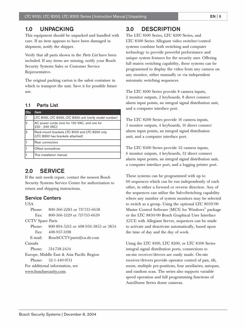
1.0 UNPACKINGThis equipment should be unpacked and handled withcare. If an item appears to have been damaged inshipment, notify the shipper.
Verify that all parts shown in the Parts List have beenincluded. If any items are missing, notify your BoschSecurity Systems Sales or Customer ServiceRepresentative.
The original packing carton is the safest container inwhich to transport the unit. Save it for possible futureuse.
1.1 Parts List
2.0 SERVICEIf the unit needs repair, contact the nearest BoschSecurity Systems Service Center for authorization toreturn and shipping instructions.
Service CentersUSA
Phone: 800-366-2283 or 717-735-6638Fax: 800-366-1329 or 717-735-6639
CCTV Spare PartsPhone: 800-894-5215 or 408-956-3853 or 3854
Fax: 408-957-3198E-mail: [email protected]
CanadaPhone: 514-738-2434
Europe, Middle East & Asia Pacific RegionPhone: 32-1-440-0711
For additional information, seewww.boschsecurity.com.
3.0 DESCRIPTIONThe LTC 8100 Series, LTC 8200 Series, and LTC 8300 Series Allegiant video switcher/controlsystems combine both switching and computertechnology to provide powerful performance andunique system features for the security user. Offeringfull matrix switching capability, these systems can beprogrammed to display the video from any camera onany monitor, either manually or via independentautomatic switching sequences.
The LTC 8100 Series provide 8 camera inputs, 2 monitor outputs, 2 keyboards, 8 direct connect alarm input points, an integral signal distribution unit,and a computer interface port.
The LTC 8200 Series provide 16 camera inputs, 5 monitor outputs, 4 keyboards, 16 direct connectalarm input points, an integral signal distribution unit, and a computer interface port.
The LTC 8300 Series provide 32 camera inputs, 6 monitor outputs, 4 keyboards, 32 direct connectalarm input points, an integral signal distribution unit,a computer interface port, and a logging printer port.
These systems can be programmed with up to 60 sequences which can be run independently of eachother, in either a forward or reverse direction. Any ofthe sequences can utilize the SalvoSwitching capabilitywhere any number of system monitors may be selectedto switch as a group. Using the optional LTC 8059/00Master Control Software (MCS) for Windows® packageor the LTC 8850/00 Bosch Graphical User Interface(GUI) with Allegiant Server, sequences can be madeto activate and deactivate automatically, based uponthe time of day and the day of week.
Using the LTC 8100, LTC 8200, or LTC 8300 Seriesintegral signal distribution ports, connections to on-site receiver/drivers are easily made. On-sitereceiver/drivers provide operator control of pan, tilt,zoom, multiple pre-positions, four auxiliaries, autopan,and random scan. The series also supports variablespeed operation and full programming functions ofAutoDome Series dome cameras.
Qty Item
1 LTC 8100, LTC 8200, LTC 8300 unit (verify model number)
2 AC power cords (one for 120 VAC, and one for 220 - 240 VAC)
2 Rack-mount brackets LTC 8100 and LTC 8200 only (LTC 8300 has brackets attached)
1 Rear connectors
1 Offset screwdriver
1 This installation manual

EN | 9
Bosch Security Systems | December 8, 2004
LTC 8100, LTC 8200, LTC 8300 Series | Instruction Manual | Description
With its built-in alarm interface capability, an externalcontact closure or logic level can be used toautomatically display any camera. Any monitor orgroup of monitors can be set to display cameras underalarm conditions. The base system contains three built-in alarm response modes: basic, auto-build, andsequence and display. In addition to these threemodes, the PC based software packages offerVersAlarm - a new dimension in alarm handling.VersAlarm has the ability to combine any or all threestandard modes. Alarm video may be selected to reset either manually or automatically. In addition, a16 character alarm title can be selected to appearinstead of the camera title during alarm conditions.
System operation and programming is accomplishedusing a full-function, ergonomically designed keyboard.Multiple keyboards may be used in the system. Built-inoperator priority levels and the ability to restrictcertain operators from controlling designated functionsprovide maximum flexibility.
The LTC 8100, LTC 8200, and LTC 8300 Seriesincludes a black outlined 48 character on-screendisplay for time-date, camera number, camera ID (16 characters), and monitor (12 characters) or statusinformation. When programming camera ID andmonitor titles, 235 different characters are available.
Enhanced programming and switching features can beobtained by utilizing a standard Windows equippedPC and the optional LTC 8059/00 MCS for Windowspackage or LTC 8850/00 GUI software. A user-friendly spreadsheet format provides the ability toenter camera titles, enter operator names, schedule 64 timed events, change system parameters, programcamera sequences, install lockouts, and access theadvanced VersAlarm alarm handling screens withspeed and efficiency. The programmed informationmay then be transferred into the Allegiant system,stored on disk, or printed from a PC.
The LTC 8850/00 Bosch GUI software is designedaround an intuitive graphic-based interface. The GUIprovides high performance programming, control andmonitoring of all system functions by using on-screenicons to reflect real time status of the devicescontrolled by the system.
The LTC 8850/00 GUI software also provides theability to monitor system status events. System alarms,switching functions, sequence events, keyboard actions,and video loss information can be viewed in real timeon the PC screen and, if desired, logged to the PC hard drive.
The LTC 8850/00 GUI software can also be used to enable a special on-screen icon for identifyingcontrollable cameras.
The CPU inside these matrix switchers supportspowerful macro capabilities. The macros can beactivated using system keyboards, system time eventfunctions, alarm activations, and via special functionicons in the LTC 8850/00 GUI software.
The LTC 8100, LTC 8200, or LTC 8300 Series canserve as the master switcher in a SatelliteSwitchconfiguration. This innovative SatelliteSwitch featureenables a single LTC 8100, LTC 8200, or LTC 8300Series system to communicate with remotely located"Satellite" systems. Any Allegiant system model canserve as a remote Satellite switcher. This powerfulfeature permits the design of a distributed matrix videoswitching system with control at one central locationand individual control at the local sites. The maincontrol site can view/control local cameras pluscameras located at any of the remotely distributedSatellite sites. The Satellite sites can view/control onlycameras associated with their own site. When thesemodels are used in this type of configuration, the mainsystem can access up to 256 cameras located anywherein the system.

EN | 10
Bosch Security Systems | December 8, 2004
LTC 8100, LTC 8200, LTC 8300 Series | Instruction Manual | Allegiant Feature Summary Table
4.0 ALLEGIANT FEATURESUMMARY TABLE
The Allegiant LTC 8100, LTC 8200, and LTC 8300 Seriessystem are available in two operating configurations: abase system and the base system with an optional PCbased software package. The base system includesfeatures required for most switching/controller systems.
The addition of the optional LTC 8059/00 MCS for Windows or optional LTC 8850/00 GUIsoftware package enables the user to customize thesystem’s configuration using a menu driven programrun on any personal computer using Microsoft®
Windows 95, 98 SE, ME, NT, 2000, or XP.The following TABLE lists available features.
Base With OptionalAllegiant PC-Based
Feature System Software1. Full camera switching/control on all monitors Y Y2. Up to 4 (LTC 8300 and LTC 8200) or 2 (LTC 8100) external keyboards Y Y3. 32 Alarm inputs (LTC 8300), 16 alarms (LTC 8200), 8 alarms (LTC 8100) Y Y4. 3 User-selectable pre-defined alarm response modes Y Y5. Full control of on-site receiver/drivers Y Y6. SalvoSwitching Y Y7. 60 Programmable sequences Y Y8. Alarm call-up of pre-position scenes Y Y9. RS-232 Interface port for Computer
(all models), Logging Printer (LTC 8300 only) Y Y10. Keyboard logon/logoff function Y Y11. User-selectable password security Y Y12. 16 Character camera titles and 12 character monitor titles Y Y13. Format selection time/date format Y Y14. Local keyboard test function Y Y15. Table and Sequence printout feature (LTC 8300 only) Y Y16. Parameter designation for RS-232 communication Y Y17. Integral video loss detection N Y18 Satellite configurations N Y19. Restrict user/keyboard access to cameras N Y20. Restrict user/keyboard access to receiver/drivers N Y21. Restrict user access to keyboard N Y22. Restrict user/keyboard access to monitors N Y23. Designate user name and ID number N Y24. Designate zoned alarm call-ups N Y25. VersAlarm alarm feature N Y26. Designate displayed camera number N Y27. Designate receiver/driver functions on alarm N Y28. Program 64 Time Activated Events N Y29. Designate receiver/driver functions in sequences N Y30. Broadcast monitor messages N Y31. Alarm title designation N Y32. Personal computer displayed monitoring of system status N Y33. Personal computer emulation of system keyboard N Y

EN | 11
Bosch Security Systems | December 8, 2004
LTC 8100, LTC 8200, LTC 8300 Series | Instruction Manual | System Accessory Components
In addition, the LTC 8100, LTC 8200, and LTC 8300Series systems provide the capability to control on-sitereceiver/driver units and the AutoDome Series ofintegral pan/tilt/zoom/camera dome series.
The LTC 8300 Series systems contain a logging printeroutput port, to which an inexpensive RS-232 serialprinter may be attached. This provides a permanentrecord showing time and date of changes to systemstatus, such as:
1. Incoming Alarms
2. Acknowledgment of alarms by users
3. Loading sequences
4. User logon to keyboard or console port
5. Console broadcast message
6. Console transfer of system tables
7. Activation of Time Event Functions
8. Power up reset message
9. Video loss message
The printer may also be used to provide a hard copyof all system configuration Tables and Sequences.
If a logging printer port is required for the LTC 8200or LTC 8100 Series system, the console port can beconverted to operate in this mode via DIP switchconfiguration, or by the appropriate command viaCommand Console Language (CCL). Refer to theCCL manual available for download from our web sitefor details.
If a logging printer and a standard console port arerequired for the LTC 8200 or LTC 8100 Series systems,an LTC 8712 Series Console Port Expander can beused to add additional console ports to the system.
5.0 SYSTEM ACCESSORYCOMPONENTS
The Allegiant Series accessory products provide many optional features to the base system. A briefdescription of accessory products is provided below.Complete specification information can be found inrespective product data sheets. Applicable accessoriesare designed to be compatible throughout the AllegiantSeries.
5.1 Alarm InterfaceThese systems contain an integral 32 (LTC 8300), 16 (LTC 8200), or 8 (LTC 8100) input alarm inputcapability. The series also provides 6 (LTC 8300), 5 (LTC 8200), or 2 (LTC 8100) alarm output relays forconnecting external alerting devices or VCRs. Theseparate LTC 8540/00 Alarm Interface accessory is not applicable to the LTC 8100, LTC 8200, or LTC 8300 Series.
5.2 Signal Distribution The series contain an integral signal distribution unitfor communicating to Receiver/Drivers, SwitcherFollowers, and Satellite systems. The integral unitprovides 16 (LTC 8300), 12 (LTC 8200), or 8 (LTC 8100) outputs, each capable of driving up to 8 remote devices. Either star or daisy chain wiringconfigurations may be used. The separate LTC 8568/00and LTC 8768/00 Signal Distribution accessory units,are not applicable to the series.
5.3 IntuiKey Keyboard This full-function, multipurpose keyboard is used forsystem control and programming, and includes integralpan/tilt/zoom joystick and a splash resistant design.The IntuiKey’s LCD displays and softkeys provide amenu driven system for ease of use, supporting amultitude of languages.
5.4 LTC 8555/00 and LTC 8555/01 Series Keyboards
These full-function, compact keyboards are used forsystem control and programming and include integralpan/tilt joystick with LED readouts to display cameraand monitor numbers.
The LTC 8555/01 is identical to the LTC 8555/00, buthas ICON characters instead of English text.
5.5 LTC 8555/02 and LTC 8555/03 Series Keyboards
These keyboards are similar to the LTC 8555/00except that RS-232 protocol is used for datacommunication. These keyboards have the capability ofremotely locating an Allegiant keyboard via RS-232transmission medium such as phone line modems, fiberoptics, etc. Requires a full duplex RS-232 link capableof operating at 9600 baud. All other specifications arethe same as for the LTC 8555/00 keyboard.

EN | 12
Bosch Security Systems | December 8, 2004
LTC 8100, LTC 8200, LTC 8300 Series | Instruction Manual | System Accessory Components
These keyboards connect to an Allegiant’s console port or to a port provided by an LTC 8712 ConsoleExpander accessory unit. Up to 4 may be connected to a single LTC 8712 unit. When used with dial-up typephone modems, these keyboards provide rudimentarydialing capability.
The LTC 8555/03 is identical to the LTC 8555/02, but has ICON characters instead of English text.
5.6 KBD-Rack Keyboard Mounting Kit
Rack-mounting kit designed to provide vertical,horizontal, or inclined mounting for IntuiKeykeyboards.
5.7 LTC 8558/00 Keyboard Extension Cable
Six-conductor extension cable that carries data/powerfor remote keyboards up to 30 m (100 ft) away frommain CPU bay.
5.8 LTC 8557 Series Keyboard Extension Kits
Interface kit used to remote keyboards up to 1.6 km (5000 ft) away from main CPU bay. Customer-supplied24 gauge shielded twisted pair (Belden 9841 orequivalent) required between main CPU bay site andkeyboard site. Kit provides two junction boxes, interfacecable, and appropriate keyboard power supply.
5.9 LTC 8560 Series Receiver/Driver Units
Decodes data transmitted from the biphase control dataoutputs of the Allegiant system, for camera site control ofPan/Tilt, Zoom Lens, pre-positions, and auxiliaries. Unitcontains integral local test feature, autopan or randomscanning, and is available in several input and outputdrive voltage versions.
5.10 AutoDome SeriesIntegral camera, high speed pan/tilt, zoom lens, andreceiver/driver system in compact dome enclosure.Various enclosure mounting options are available forindoor and outdoor applications.
5.11 LTC 8569, LTC 8570, LTC 8571, LTC 8572 Series Code Merger Unit
Control code merger and line driver unit used tocombine control code from two systems (up to four with LTC 8570 model) for communicating toReceiver/Drivers, Switcher Followers, and satellitesystems. Provides 32 or 64 outputs capable of driving upto 256 or 512 remote devices. Either star or daisy chainwiring configurations may be used. Unit will accept signalinput either from Allegiant main CPU bay, LTC 8568output, or an output from another code merger unit.Multiple units may be cascaded to obtain additionaloutputs.
5.12 LTC 8770 Switcher Follower Series
Accessory unit which provides relay contact closurescorresponding to cameras displayed on system monitors.The LTC 8770 may be configured to follow non-alarmedvideo, alarmed video, or both. Each unit provides 24 relay contact outputs.
5.13 LTC 8712 Series Console Port Expander Units
The LTC 8712 Series port expander interfaces to the RS-232 Console port of an Allegiant system to permit up to 4 external PCs, logging printers, or othercomputing devices. This permits multiple PCs orcomputing devices to communicate with a singleAllegiant system.
5.14 LTC 8780 Series Data Converter Units
The LTC 8780 Series convert the biphase control codegenerated by Allegiant Series matrix switchers intostandard RS-232, and converts RS-232 back to biphasecode. This provides transmission of the biphase controlcode over conventional RS-232 transmission media(phone modems, fiber optics, microwaves, etc.). The LTC 8780 Series can also be used to perform the Satellite Selector functions in Allegiant satellite systemconfigurations and operate as a 15-channel remote signaldistribution unit.

EN | 13
Bosch Security Systems | December 8, 2004
LTC 8100, LTC 8200, LTC 8300 Series | Instruction Manual | System Accessory Components
5.15 LTC 8785 Series Code ConvertersLTC 8785 Series units are designed for use in pre-1996Allegiant systems which have been upgraded to operateAutoDome Series of cameras. The LTC 8785 Series CodeConverters are used to provide the source for the fixedspeed control code when the system is generating thenew variable speed control code preferred by theAutoDome cameras. The LTC 8785 Series CodeConverter receives the variable speed control code fromone of the Allegiant Signal Distribution outputs andconverts it into the appropriate fixed speed control code.Outputs from the LTC 8785 Series Code Converter maybe connected to older LTC 8561 Series receiver/driversusing existing field cables.
5.16 LTC 8782 Series Code Translator Units
Code translators convert Allegiant control code to andfrom other manufacturer’s code formats. Contact yourlocal manufacturer’s representative for additionalinformation.
5.17 LTC 8808/00 Video Interconnect Panel
Optional accessory item which provides the LTC 8300 orLTC 8200 Series systems with the capability of looping itsvideo inputs (the LTC 8100 provides integral BNCs forlooping so the LTC 8808/00 is not required). This patchpanel contains 32 BNC connectors on front for externalvideo connections, and two 16-contact ribbon connectorson the rear. Two 16-conductor ribbon cables are includedfor interfacing the patch panel to the video loopingconnectors on the LTC 8300 or LTC 8200 Seriesequipment bay (only one ribbon cable is used for theLTC 8200). The patch panel is one standard EIA 19-inchrack unit high, and one unit wide.
5.18 LTC 8059/00 Series Allegiant Master Control Software for Windows
The LTC 8059/00 Series Allegiant MCS for Windowsconsists of a Windows NT, Windows 95 or Windows 98compatible program for configuration of standard systemfeatures. The program provides advanced alarm andsequence programming, in addition to other features notavailable via the system keyboard. Online real timemonitoring of system status is also included.
Other standard MCS for Windows features include: userpasswords, lockout tables, 64 programmable time eventfunctions, and custom alarm responses using theVersAlarm alarm mode. In addition to the operationalswitching sequences entered via standard keyboard, morecomplex switching sequences may be programmed, toincorporate remote control commands into the switchingsequence. Video loss detection in LTC 8100, LTC 8200,and LTC 8300 Series systems and monitoring of allsystem operation in real-time, are standard features of theAllegiant MCS for Windows package.
5.19 LTC 8850/00 Windows Based Graphical User Interface Allegiant Software
The LTC 8850/00 software package uses a GUI tointegrate and control security systems. The GUIinterfaces directly to the Allegiant system and providescomplete control and programming of all system features.Refer to the LTC 8850/00 data sheet for specifications.
5.20 Logging PrinterAn optional RS-232 serial printer may be connected tothe LTC 8300 Series to provide a permanent record ofsignificant system status changes. Time and date isprinted for system events such as alarms, start-up afterpower failure, sequence loading, operator logon/logoff tokeyboards, and download of information from theoptional MCS for Windows or LTC 8850/00 GUI. Theprinter may also be used to obtain hard copies of allsystem Tables and Sequences.
NOTE: The Printer port does not provide a standardizedpinout connection. An interface cable designed for astandard serial printer connection is available. If desired,a cable can be made up at installation, by following thecable pinout information provided at the end of thismanual.

EN | 14
Bosch Security Systems | December 8, 2004
LTC 8100, LTC 8200, LTC 8300 Series | Instruction Manual | System Accessory Components
Up to 32Video Inputs
MaximumAdditionalSystem Cameras
1 2 3
4 5 6
7 8 9
0
Shot
MonProd
Clr
BOSCH
1 2 3
4 5 6
7 8 9
0
Shot
MonProd
Clr
BOSCH
LTC 8300 SeriesMain CPU Bay
3 m (10 ft) InterconnectCable Supplied with Keyboard
Video CoaxUp to 6
Monitor Outputs
Maximum of four Allegiant SeriesFull Function Keyboards up to 1.5 km (5000 ft)
away using optional Remote Hookup Kit
Monitor 1 Monitor 2 Monitor 3 Monitor 4 Monitor 5 Monitor 6
Figure 1 LTC 8300 Series Video Switching System

EN | 15
Bosch Security Systems | December 8, 2004
LTC 8100, LTC 8200, LTC 8300 Series | Instruction Manual | System Accessory Components
AutoDome®
1 2 3
4 5 6
7 8 9
0
Shot
MonProd
Clr
BOSCH
1 2 3
4 5 6
7 8 9
0
Shot
MonProd
Clr
BOSCH
LTC 8300 SeriesMain CPU Bay
3 m (10 ft) InterconnectCable Supplied with Keyboard
Video Coax
Video Coax
VideoCoax
Video Coax
Video Coax
Up to 6 Monitor Outputs
Maximum of four Allegiant SeriesFull Function Keyboards up to 1.5 km (5000 ft)
away using optional Remote Hookup Kit
Monitor 1 Monitor 2 Monitor 3 Monitor 4 Monitor 5 Monitor 6
Pan/TiltReceiver/
Driver
Up to 1.5 km (5000 ft)using 18 AWG ShieldedTwisted Pair Cable(Belden 8760 orequivalent)
3 m (10 ft) Interface Cable providedwith Optional Software Package
Serial LoggingPrinter Capability
RS-232 Data
RS-232 Data
Optional LTC 8059/00 Master Control Softwareor LTC 8850/00 Graphical User Interface (GUI)Software Package can be Run on Windows® based PC.
6 Pairsof RelayOutputs
Contact Closureor Active Low Logic Level
Twisted-PairTypical
32 SeparateAlarm Inputs
AdditionalSystem Cameras
Figure 2 LTC 8300 Series Full Capacity Configuration

EN | 16
Bosch Security Systems | December 8, 2004
LTC 8100, LTC 8200, LTC 8300 Series | Instruction Manual | Installation Procedure
6.0 INSTALLATION PROCEDURECAUTION: Do Not Apply Power toEquipment Until Instructed to do so.
6.1 Internal SelectionsThe LTC 8100, LTC 8200, and LTC 8300 Seriesincorporate printed circuit boar/ds (PCB) that contain user-selectable DIP switches. If necessary, follow theinstructions in the COVER REMOVAL Section below toaccess the DIP switches. Removal of the cover shouldonly be performed by qualified service personnel.
The LTC 8x00 Series circuit board contains the videoinput termination switches S0801, S0802, S0803, andS0804 (S0803 and S0804 are only present on the LTC 8300 Series). The video termination switches on theAllegiant must be set to the correct position prior toinstallation. Read the TERMINATION PRACTICES Sectionprior to installing the system to determine if it isnecessary to change the video module terminationswitches.
The circuit board contains two 8-position DIP switchesfor system configuration options, and two lithiumbatteries. The DIP switches can be used to modify certainsystem operating conditions. Review the FACTORYDEFAULT SETTINGS Section to determine if it isnecessary to change the DIP switches from the factorydefault positions.
The circuit board’s lithium batteries require attention onlywhen it is necessary to change them. These batteriesenable the RAM memory to retain its contents for up toa year without power. Since the batteries are not usedwhile the AC power is on, several years of service shouldbe expected before it becomes necessary to change them.
6.2 Enclosure MountingIf the unit is to be installed into a standard 19-inch EIArack, remove the four (4) rubber bumper foot pads on thebottom. Four holes are provided for mounting the bay inthe rack.
The LTC 8300 is supplied with the rack-mountingbrackets attached. The LTC 8200 and LTC 8100 areshipped with the rack-mounting brackets unattached. On these systems, the brackets must be attached prior to being installed into a rack. Use the supplied offsetscrewdriver to remove the two (2) star head screwslocated on each side near the front of the unit. Thenattach the supplied rack mounting brackets to the unit.
If the LTC 8300 Series are not going to be rack-mounted,the enclosure’s mounting brackets can be removed. Thecover of the unit must be removed before access to themounting brackets is possible.
6.3 Cover Removal
Cover removal is necessary only if changes need to bemade to the video input termination switches, systemconfiguration DIP switches, or batteries.
For the LTC 8300, the top cover is fastened to the case by 4 screws located on the rear of the unit. For theLTC 8100 and LTC 8200 units, the top cover is fastenedby 8 screws on the top and 4 screws on each side. Usethe supplied offset screwdriver to remove the star headscrews. After the screws have been removed, the coverslides back and off the unit. Reverse procedure to re-install.
WARNING: Electrostatic-sensitive device. Useproper CMOS/MOSFET handlingprecautions to avoid electrostatic discharge.
NOTE: Grounded wrist straps must be worn and proper ESDsafety precautions observed when handling the electrostatic-sensitive printed circuit boards.
ATTENTIONOBSERVE PRECAUTIONS
FOR HANDLING ELECTROSTATIC SENSITIVE
DEVICES
Cover RemovalWARNING: Removal of the cover should only be performed by qualified service personnel - not user serviceable. The unit should always be unplugged beforeremoving the cover and remain unplugged while the cover is removed.

EN | 17
Bosch Security Systems | December 8, 2004
LTC 8100, LTC 8200, LTC 8300 Series | Instruction Manual | Installation Procedure
6.3.1 Mounting Ear RemovalIf the LTC 8300 Series is to be used as a desk top unit, remove each mounting ear by removing the screw holding the mounting ear to the enclosure chassis (see Figure 3).
Figure 3 Cover and Rack Brackets Removal
6.3.2 Video Termination SelectionsThe video input termination DIP switches are locatedtoward the rear of the circuit board. Note that theFactory Default Settings are all ON (input terminated with 75Ω). Only those switches associated with loopingvideo inputs need to be changed to OFF (unterminated).
6.3.3 CPU Module SelectionsTo access the circuit board, remove the cover and lid asdescribed in the COVER REMOVAL Section. The batteriesand the two 8-position system configuration DIP switches(S0201 and S0202) near the front of the unit will now bevisible. Change only the desired CPU DIP switchesbased on the features described in the FACTORY DEFAULTSETTINGS Section of this manual.
6.3.4 Battery Replacement
If the batteries have reached the end of their useful life,the Time and Date portion of on-screen display willbegin to alternate with an indication of ?? ?? ??. TheLED on the front panel of the unit will also light,indicating a low battery condition. Access the circuitboard as described in the INTERNAL SELECTIONSSection above, then follow the instructions found in theMAINTENANCE INFORMATION Section of this manualfor replacement procedures.
6.4 Termination PracticesVideo from every camera should be terminated with a 75Ω resistance. Each video line should be terminatedexactly once. If video from a camera is going to severaldevices, only the last device on the video line should beterminated.
6.4.1 Video TerminationsThe main circuit board has DIP switches to select thetermination of each video line. To terminate an input line,ensure that the appropriate DIP switch on the videomodule is ON (Factory Default Setting). If non-terminated operation is required for looping purposes,turn the switch OFF. See the TABLE below to determinethe DIP switch numbers that correspond to video input.
Video Switch Switch SystemsInputs No.
1-4 S0801 1-4 LTC 8100, LTC 8200, LTC 8300
5-8 S0802 1-4 LTC 8100, LTC 8200, LTC 8300
9-12 S0801 5-8 LTC 8200, LTC 8300
13-16 S0802 5-8 LTC 8200, LTC 8300
17-20 S0803 1-4 LTC 8300
21-24 S0804 1-4 LTC 8300
25-28 S0803 5-8 LTC 8300
29-32 S0804 5-8 LTC 8300
Video Input Termination Switches
If looping video inputs are desired, the LTC 8200 and theLTC 8300 Series require an optional LTC 8808/00 patchpanel (for the LTC 8100 Series, the looping BNCs areincluded on the unit). A single LTC 8808/00 provideslooping capability for all 16 (LTC 8200) or 32 (LTC 8300)video inputs. If necessary, refer to the Section onLOOPING VIDEO CONNECTIONS below.
Just like camera inputs, monitor outputs on the Allegiantsystem are designed to be terminated. Each monitoroutput expects to be connected to a 75Ω load. This is theload typically provided by a monitor. If a monitor outputline is looped through several monitors or otherequipment, ensure that only the last unit on the line isterminated.
CAUTION: Lithium Battery Danger of explosion if battery is incorrectly replaced.Replace only with the same or equivalent typerecommended by the manufacturer. Dispose of usedbatteries according to the battery manufacturer’sinstructions.

EN | 18
Bosch Security Systems | December 8, 2004
LTC 8100, LTC 8200, LTC 8300 Series | Instruction Manual | Installation Procedure
6.5 Looping Video ConnectionsThe Allegiant Series has outputs available for video input looping connections. Looping connections for LTC 8200 and LTC 8300 require the optional LTC 8808/00 Video Interconnect (patch) Panel. Thepatch panel provides 32 BNCs for video connections.Patch panels are connected to the rear of the main bayvia supplied ribbon cables. Each cable can carry videofor up to 16 cameras. For LTC 8300 Series systems, 2 cables can be attached to the patch panel to support up to 32 cameras. Each ribbon cable should be attachedto the appropriate VIDEO connector on the rear of themain bay.
LTC 8808/00 Typical Use
Figure 4 Video Interconnect Panel
6.6 Keyboard Hookup Connect a maximum of 4 (LTC 8300 or LTC 8200Series) or 2 (LTC 8100 Series) system keyboards to any of the keyboard ports (modular phone type jacks)provided on the rear of the main bay. Be sure to connect a keyboard to at least port #1.
NOTE: The LTC 8555 Series RS-232 type keyboards are not connected to the standard keyboard ports. The keyboards connect to the Console port, or to a LTC 8712 Series Port Expander. Note that when LTC 8555 RS-232 type keyboards are connected to the system, the corresponding standard keyboard ports are automatically disabled.
Each keyboard is supplied with a 3 m (10 ft) cable forlocal hookups. Allegiant systems can provide power to keyboards up to 30 m (100 ft) away via the optional LTC 8558/00 hookup cable. For distances of up to 1.5 km (5000 ft), the optional LTC 8557 Series hookup kit is required. This product is supplied with a remotepower pack, and requires user-supplied shielded twistedpair (Belden 9841 or equivalent) for communication.
6.7 Biphase Control Code Output Connections
Allegiant systems provide separate outputs (16 for LTC 8300, 12 for LTC 8200, 8 for LTC 8100 Series) fordriving remote receiver/drivers, switcher/followers, andsatellite systems. Either star or daisy chain wiringconfigurations may be used.
Connect shielded twisted pair cable between the camerasite receiver/driver locations (or other accessory device)and any of the outputs provided on the Allegiant’s rearpanel. Use the straight slot side of the supplied offsetscrewdriver to tighten the terminal block screws.Maximum transmission distance is 1.5 km (5000 ft) using 1 mm2 (18 AWG) shielded twisted pair (Belden 8760 orequivalent). Contact removable screw terminal blocks areprovided with up to 4 separate connection groups perblock. Each group provides three connections; +, –, and S(Shield). Do not mix connections between groups, i.e.connecting one wire of the cable to the + of one group andanother wire of the same cable to the – of another group.Each output is rated to handle up to 8 receiver/drivers, asin a daisy chain configuration, to a maximum of 1.5 km(5000 ft). Select and maintain a wire color convention toavoid confusion at the various camera sites.
Example: White to +, Black to –, and Shield to S.
The CODE OUT LED located on the Allegiant frontpanel will flash when the joystick, a lens control, or avideo switching action is activated. The CODE OUTLED also flashes occasionally when system statusinformation is being generated by the system.
6.8 External Alarm ConnectionsThe LTC 8100, LTC 8200, and LTC 8300 Series containintegral alarm input and output connections. These alarminputs provide automatic display of video under alarmconditions. The units accept up to 32 (LTC 8300), 16 (LTC 8200), 8 (LTC 8100) contact closures or logiclevel inputs from remote sensing devices (door contacts,PIRs, etc.). The alarm inputs are designed to generatealarm conditions upon closure of the external contacts(normally open contacts). The units also provide 6 (LTC 8300), 5 (LTC 8200), or 2 (LTC 8100) relayclosure outputs upon alarm conditions.
Alarm input connections are made to 12 contactremovable screw terminal blocks located on the rear panel.Each terminal block provides 8 alarm input connections.
Lower LTC 8809/00 Cable
Upper LTC 8809/00 Cable
LTC 8300

EN | 19
Bosch Security Systems | December 8, 2004
LTC 8100, LTC 8200, LTC 8300 Series | Instruction Manual | Installation Procedure
Connect any 2-conductor shielded wire (the shield andground wire are both connected to the connector pinslabeled G) between the alarming device (contact closureor logic level) and the appropriate Allegiant input. Usethe straight slot side of the supplied offset screwdriver totighten the terminal block screws. The alarm inputnumbers are marked on the removable connector block.Note that every two alarm inputs share a commonground connection. The total wire loop resistanceshould not exceed 1,000Ω. Input #1 corresponds tocamera #1 in the Factory Default Settings, but thisrelationship can be changed via programming with theoptional LTC 8059/00 MCS for Windows package orLTC 8850/00 GUI software package.
Allegiant units also provide isolated alarm relay outputs.An alarm output is typically used to activate the alarminput of a security DVR/VCR or other alerting device. AVCR is normally programmed to change recordingspeeds from a slower time lapse mode to a faster realtime mode upon alarm activation. Operation of the relayoutputs depends on the system configuration forresponding to alarm events. The alarm output relaysactivate accordingly under the following conditions:
1. Relay 1 activates if the system is set to use theBasic alarm response mode, and an alarm occurson any system monitor. Relay 1 deactivates afterall alarms have been removed from the inputs.Relay 1 also deactivates if the system (monitor oralarm(s)) is disarmed by an operator via thekeyboard. Pressing Acknowledge on the systemkeyboard does not deactivate Relay 1 since thealarm video follows the contact applied to the unitin this alarm response mode. Other relays arenot used in this mode.
2. Relay 1 activates if the base system is set to usethe Sequence & Display alarm response modeand an alarm occurs on any system monitor.Relay 1 deactivates after all alarm videos havebeen acknowledged (by pressing theAcknowledge key) via system operator(s) from all system monitors. Relay 1 also deactivates if the system is disarmed (either the monitor or the alarm(s)) by an operator via the keyboard.Removal of the alarm input does not deactivateRelay 1 since the alarm video(s) are notdependent on duration of the contact applied tothe unit in this alarm response mode. Other relaysare not used in this mode.
3. If the base system is set to use the Autobuildalarm response mode, and an alarm occurs onsystem monitors, the relay corresponding to themonitor number activates for the duration that thecorresponding alarm input is applied to the unit.The relay deactivates if the monitor associatedwith the relay or if the alarm(s) being displayed onthe monitor is disarmed by an operator via thekeyboard. Pressing Acknowledge on the systemkeyboard does not deactivate the relays since thealarm video follows the contact applied to the unitin this alarm response mode.
4. If the VersAlarm Group table screen in the PC- based LTC 8059/00 MCS for Windowspackage or the LTC 8850/00 GUI softwarecontains an alarm group that includes monitors,and the Monitor option has been selected in theRelay Action column, the corresponding relayactivates for the duration the alarm video remainson the monitor. The relay deactivates if theassociated monitor (or the alarm(s) beingdisplayed on the monitor) is disarmed by anoperator via the keyboard. Pressing Acknowledgeon the system keyboard does not deactivate therelay unless this feature has been selected for theassociated alarm group. If the Monitor option hasbeen set to 1 in the Group table, only Relay 1activates when monitors in that alarm groupbecome alarmed.
Typically, any 2-conductor wire can be used between therear panel terminal block containing the relay outputs,and the VCR alarm input. Use the straight slot side of thesupplied offset screwdriver to tighten the terminal blockscrews. If another external device is to be controlled, donot exceed the relay ratings of 1 A, 40 VAC/DC.
6.9 Satellite Configuration InstallationsDue to many variables, only general guidelines will becovered for installing satellite systems. Refer to theAPPENDICES of this manual and either the LTC 8059/00 MCS for Windows or LTC 8850/00 GUIsoftware manual for additional information on satellitesystems.

EN | 20
Bosch Security Systems | December 8, 2004
LTC 8100, LTC 8200, LTC 8300 Series | Instruction Manual | Installation Procedure
Figure 5 Satellite Concept Configuration
6.9.1 Satellite Site Trunk Line Monitor OutputsAt each of the remote satellite sites, a desired number ofmonitor outputs from the switcher must be assigned astrunk lines. The number of trunk lines can range from 1 to the maximum number of monitor outputs providedby the switcher. Note that the number of trunk linescoming from a satellite site determines the maximumnumber of cameras from that site that may be viewedsimultaneously at the main site. If operators will bestationed at the satellite site, they should be preventedfrom accessing the monitor outputs designated as trunklines. This can be accomplished via the MonitorLockout tables in either the LTC 8059/00 MCS forWindows or the LTC 8850/00 GUI software (see below).
6.9.2 Main Site Trunk Line Video InputsAt the main site, video trunk line connections comingfrom each of the remote site(s) should be connected (andproperly terminated) using an available video input at the main bay. There are no programming restrictionsconcerning their connections, but a sense of order can be maintained if a group of video inputs are used at theupper end of the system’s designed capacity. This allowsthe main system to be more easily expanded in the future with additional local cameras or trunk lines. As an example, assume that there are a total of 8 trunk linescoming from all satellite sites which will be connected toa main site system designed for 32 inputs. Inputs 25 to 32can be reserved for the trunk lines, leaving inputs 1 to 24for local camera connections. If there will be no localcamera inputs, the trunk lines can start at the first videoinput.
6.9.3 Control Data Lines in Satellite SystemsEach satellite site must be provided with an Allegiantbiphase control data line coming from the SignalDistribution located at the main site. The SignalDistribution unit is an integral part of the LTC 8100, LTC 8200, and LTC 8300 Series. This data line carries all pan/tilt/zoom control commands, in addition to theswitching commands generated by the main site switcher.The control data line should be connected to an LTC 8780 Series Data Converter unit, which providesaddress decoding functions for the satellite site. An LTC 8780 Series is required at each satellite site, and must be given a unique site address number.
If operators stationed at the satellite site are permitted tocontrol pan/tilt/zoom-equipped cameras, an LTC 8569Series Code Merger unit must be installed at the satellitesite. The Code Merger combines code generated by themain site and the satellite sites so both sites have controlover pan/tilt/zoom-equipped cameras at the satellite site.The LTC 8780 Series can then be connected to one of thedata outputs of the LTC 8569 Series unit.
6.9.4 Satellite Site Programming RequirementsThe optional LTC 8059/00 MCS for Windows or theoptional LTC 8850/00 GUI software is required toproperly program a satellite system.
Programming the satellite sites is usually limited todesignating their logical camera numbers to appropriatevalues via the Camera ID table of the MCS or GUIsoftware.
Note that no duplicate camera numbers are permittedanywhere in the system. Allegiant logical cameradesignations can be renumbered to any four-digit numberon the LTC 8100, LTC 8200, LTC 8300 Series, LTC 8600Series, LTC 8800 Series, or LTC 8900 Series systems, andany three-digit number on LTC 8500 systems.
Few other restrictions exist. These camera numbers arethe numbers entered at both the satellite and the mainsite keyboards when camera selections are made. On anypan/tilt/zoom-equipped camera, this logical number mustalso be entered as the receiver/driver’s site addressnumber.
CentralControlStationVideo and
Data Links
S9507002AE
SatelliteSysem
#6
SatelliteSysem
#5
SatelliteSysem
#4
SatelliteSysem
#3
SatelliteSysem
#2
SatelliteSysem
#1

EN | 21
Bosch Security Systems | December 8, 2004
LTC 8100, LTC 8200, LTC 8300 Series | Instruction Manual | Installation Procedure
To maintain a sense of order, it is preferable to program asatellite for a range of camera numbers. For example, in athree Allegiant type satellite system, the first satellite canbe programmed for camera numbers 1 to 50. Satellitetwo can be programmed for camera numbers 101 to 131,and satellite three can use numbers 201 to 225.
If necessary, the MCS or GUI software Keyboard-to-Monitor Lockout table can be programmed in thesatellite switcher to prevent any local operators frominadvertently accessing the satellite’s monitor outputsbeing used as trunk lines.
If operators will be stationed at the satellite site, cameratitles should be entered into the switcher. If desired, thesetitles can be selected (explained below) to appear at themain site.
The only other requirement is to ensure that the Consoleports of all Allegiant type satellites have the handshakeoption disabled (CTS = off). This is done via keyboardUser Function 30 (see Section 13, KEYBOARD USERFUNCTIONS), the MCS or GUI software’s Parameters-System screen.
6.9.5 Main Site Programming RequirementsAt the main site, the Camera ID table must beprogrammed to ensure proper satellite operation. It iseasiest to start with the trunk line inputs. For each trunkline, the satellite’s monitor output number and its bayaddress must be entered (same number as the satellite’sLTC 8780 address).
Camera numbers should be programmed next. Noduplicate camera numbers are allowed anywhere in theentire system. Designate remote cameras (located atsatellite sites) using numbers above those at the mainbay’s physical video inputs (9+ on LTC 8100 Series, 17+ on LTC 8200 Series, 33+ on LTC 8300 Series, 65+ on LTC 8500, 129+ on LTC 8600, 257+ on LTC 8800 Series, 4097+ on LTC 8900 Series). Enter thedesired camera number, (the satellite bay that it isactually connected to), and select if either a local title willbe used, or if the remotely generated title will be used.For satellite camera entries, only those numbersrepresenting actual cameras need to be entered. Forexample, all 16 cameras associated with an LTC 8200switcher do not need to be entered if only 5 cameras areactually connected to the switcher. If desired, a few extracamera numbers may be included at this time for futureexpansion. If a local title is specified, the camera’s titlecan also be entered at this time. Designate any localcamera numbers appropriately, and enter theircorresponding titles.
NOTE: Either a local camera, or a remote cameraprogrammed with a local title, will need to be selected toview certain on-screen prompts or data duringprogramming of the main site via a system keyboard.
Once the system is programmed and configured, anyunused monitor outputs located at the main site shouldbe selected to display a local camera via the systemkeyboard. This prevents unused monitor outputs fromusing up trunk lines which may result in some confusingoperational responses.
BOSCH
BOSCH
Figure 6 Front Panels: LTC 8300 Series - Top, LTC 8200 Series, LTC 8100 Series - Bottom

EN | 22
Bosch Security Systems | December 8, 2004
LTC 8100, LTC 8200, LTC 8300 Series | Instruction Manual | Installation Procedure
6.9.6 Alarm Inputs in Satellite SystemsAny alarm inputs to the main site, which have beenprogrammed to activate cameras located at satellites, willoperate normally except when limited by the number oftrunk lines available. The software automaticallydetermines trunk usage depending on the priority level ofoperators currently viewing satellite cameras. Alarminputs applied at a satellite site will NOT activate alarmvideo at the main site. If the application requires alarmslocated at a satellite to activate video at the main site, theremote alarms must be brought back to the main site. Ifnecessary, the main site’s LTC 8540/00 Alarm Interfaceunit can be remotely located via an RS-232 link. Sincethe Alarm Interface capability is an integral part of the LTC 8100, LTC 8200, and LTC 8300 Series, this is notpossible if an LTC 8100, LTC 8200, or LTC 8300 Seriessystem is being used as the main site system. If more thanone satellite site contains alarms, multiple LTC 8540/00Alarm Interfaces can be remotely located. The number ofalarm interfaces which can be remoted is limited only bythe capacity of the main site system to support thiscapability.
6.10 Feature SelectionCertain user-selectable features can provide enhancedAllegiant system operation capabilities. Any changesinvolving configuration option DIP Switch Settings shouldbe made prior to installation. Refer to FACTORYDEFAULT SETTINGS Section for feature descriptions andinstructions.
6.11 Main Power ConnectionsConnect the AC power cord to an appropriate AC powersource. Verify that the selected LTC 8100, LTC 8200, orLTC 8300 Series model matches the desired voltageinput.
NOTES:
• The system may require several seconds to fullyinitialize after a power up reset. This time can varybased on the activity and general size of thesystem. Verify that the front panel POWER LEDlights and the front panel STATUS LED begin toblink randomly.
• ALL CAMERAS SHOULD BE PHASEDPROPERLY WITH EACH OTHER TOAVOID VERTICAL ROLLING MONITORDISPLAY DURING SWITCHING.
• THE SYSTEM IS DESIGNED TO PROVIDEVERTICAL SYNCHRONIZED SWITCHINGBASED ON THE MAIN VOLTAGE INPUTFREQUENCY.
Proceed to the next applicable accessory installationsection or immediately to the appropriate systemoperating instruction section.

EN | 23
Bosch Security Systems | December 8, 2004
LTC 8100, LTC 8200, LTC 8300 Series | Instruction Manual | Installation Procedure
Rear Panel and Alarm Input Connector Detail
Rear Panel and Alarm Input Connector Detail
Rear Panel and Alarm Input Connector Detail
A1 Gnd A2 A3 Gnd A4 A5 Gnd A6 A7 Gnd A8A9 Gnd A10 A11 Gnd A12 A13 Gnd A14 A15 Gnd A16A17 Gnd A18 A19 Gnd A20 A21 Gnd A22 A24 Gnd A24A25 Gnd A26 A27 Gnd A28 A29 Gnd A30 A31 Gnd A32
A1 Gnd A2 A3 Gnd A4 A5 Gnd A6 A7 Gnd A8A9 Gnd A10 A11 Gnd A12 A13 Gnd A14 A15 Gnd A16
A1 Gnd A2 A3 Gnd A4 A5 Gnd A6 A7 Gnd A8
Figure 10 LTC 8808/00 Video Interconnect Panel
R1 R1 R2 R2 R3 R3 R4 R4 R5 R5 R6 R6
R1 R1 R2 R2 R3 R3 R4 R4 R5 R5
+ S -- + S -- + S -- + S --
Rear Panel Biphase Outputs Connector Detail
Rear Panel Relay Outputs Connector Detail
Rear Panel Biphase Outputs Connector Detail
Rear Panel Biphase Outputs Connector Detail
Rear Panel Relay Outputs Connector Detail
Rear Panel Relay Outputs Connector Detail
R1 R1 R2 R2
+ S -- + S -- + S -- + S --
+ S -- + S -- + S -- + S --
Figure 9 LTC 8100 Series Rear Panel
Figure 7 LTC 8300 Series Rear Panel
Figure 8 LTC 8200 Series Rear Panel

EN | 24
Bosch Security Systems | December 8, 2004
LTC 8100, LTC 8200, LTC 8300 Series | Instruction Manual | Optional Accessories
7.0 OPTIONAL ACCESSORIES7.1 Logging Printer Option InstallationNOTE: Installation for each printer varies; the followingsteps are generally required. Save the printer referencemanual for procedures not covered.
• Switch the main power to the printer OFF.
• Install ribbon cartridge and paper if necessary.
• Set any configuration switches for your particularprinter to match the format provided by the LTC 8300 Series system.
• The system communication protocol can bechanged via keyboard User Function 31(see Section 13, KEYBOARD USER FUNCTIONS),the optional LTC 8059/00 MCS for Windows orthe LTC 8850/00 GUI software. Factory defaultvalues are as follows:
Baud rate 19,200Stop bits 1Data bits 8Parity None
• The required interconnect cable uses a custompinout. Refer to APPENDIX D for wiring details.
1. Attach the 25-pin male D-type connector sideof the RS-232 cable to the connector on theprinter.
2. Attach the 9-pin male connector side of thecable to the LTC 8300 Series bay connectormarked PRINTER.
• Apply power to the printer.
• Verify printer logging by loading a previouslystored sequence into a monitor, activating analarm, or performing a system reset. Any of theseactions should cause printouts to occur.
7.2 Windows-compatible Computer Interface Installation
NOTE: Installation for each computer varies; thefollowing steps are generally required. Save the computerreference manual for procedures not covered here.
• Switch the main power to the computer OFF.
• Attach the PC security key, provided with theMCS for Windows or the LTC 8850/00 GUIsoftware kit, to the computer.
• The supplied interconnect cable uses a custompinout. If it ever becomes necessary to replace the cable, it can be ordered separately (part number:LTC 8506/00). Alternatively, a cable can beconfigured using the information in APPENDIX D.
1. Attach one end of the supplied interface cableto the Allegiant bay connector markedCONSOLE.
2. Attach the other end of the cable to anavailable serial port (COM1 or COM2) on therear of the computer.
• Apply power to the computer and allow it to bootup its operating system before inserting the MCSor GUI software disc.
• Refer to the LTC 8059/00 MCS or LTC 8850/00GUI software reference manual for operatinginstructions.

EN | 25
Bosch Security Systems | December 8, 2004
LTC 8100, LTC 8200, LTC 8300 Series | Instruction Manual | Video Monitor Display
8.0 VIDEO MONITOR DISPLAYThe LTC 8100, LTC 8200, and LTC 8300 systems featurean integral text overlay with two rows of 24 characterseach. There are a total of 235 different characters that canbe displayed. Refer to Section CHARACTER ROMTABLES for further details.
NOTE: If no video signal is present, a third line willappear stating: VIDEO NOT PRESENT.
The display is broken down into five areas as shown inthe Figure 11 below:
8.1 Time / DateThe time/date display is generated by the system CPUmicroprocessor module. It is crystal controlled andbattery protected for one year (minimum) without power.The display is updated once per second and all monitorsupdate simultaneously. The time/date message is alwayson the right side of the video display with the time on thetop line. Time displays hours, minutes, and seconds, andcan be set to either 12-hour or 24-hour operation. Thedate is available in three user-selectable formats:
1. U.S. Format: MM/DD/YY
2. International Format: DD/MM/YY
3. Asian Format: YY/MM/DD
Figure 11 Monitor Overlay Display
12-Character System StatusDisplay or Monitor Title
12-or 24-HourTime Display
Camera Number
XXXX Status/Title 12:00:00Camera Title 10-20-96
16-Character Camera Title
3 Selectable Date Formats(MM-DD-YY, DD-MM-YY,
YY-MM-DD)

EN | 26
Bosch Security Systems | December 8, 2004
LTC 8100, LTC 8200, LTC 8300 Series | Instruction Manual | Video Monitor Display
8.2 Monitor Title/System Status Display
The monitor title/system status display area is a 12-column display to the right of the camera number. It is unique on each of the monitors and has different uses,some of which may be user selected via keyboard. Thevarious uses are described below.
Format of Monitor Overlay’s System Status Display
1 2 3 4 5 6 7 8 9 10 11 12
A A A M C E R M A S S S
l l l o a r e o b e e e
a a a n m r m n s q q q
r r r o /
m m m A A r L L R N N S
r r / o o e u u t
m m D c c l m m a
I k k t
R
8.2.1 System Status Display If this display is enabled (factory default), it allows theAllegiant system to dynamically inform the user of systemstatus. The 12-column display is divided into smallermessage columns (see Figure above), in which specialcharacters report the following:
• Whether the switcher is running or stopped.
• The switcher’s direction.
• Whether a monitor or remote camera is locked.
• The alarm status of the camera and monitor.
8.2.2 Locations 1, 2, and 3 - Alarm Indication When the monitor overlay is in Status Display mode,locations 1 through 3 indicate whether a camera on themonitor is in alarm. If the on-screen camera is currentlyin alarm, an ALM message in a box will flash at thislocation. A in a box means that a camera otherthan the on-screen camera is in alarm. If no cameras arecurrently in alarm on this monitor, these spaces areblank. When a monitor has cameras in alarm, pressNEXT, RUN, or PREVIOUS on the keyboard to movethrough the alarm sequencer rather than the regularcamera sequencer. The alarm switcher status will bedisplayed in location 6 using symbols described.
8.2.3 Location 4 - Monitor Arm Status Indication In the MONITOR ARMED location, the characters SM
or DM will appear if the monitor is armed for alarm. SM
means that the monitor is a step or sequence monitor,and will automatically step through multiple alarmvideos. DM indicates that the monitor is a display orreview monitor, which will collect alarm videos fromone or more step monitors.
When an alarm occurs, the alarmed camera’s video willreplace the current display of the monitor. If the monitoris not armed, this location is blank.
8.2.4 Location 5 - Camera Arm Status Indication In the CAMERA ARMED location characters CA aredisplayed if the camera being viewed is armed for alarmon that monitor. If the alarm signal associated with thiscamera becomes active, the camera will be displayed onthe appropriate armed monitors.
8.2.5 Location 6 - Error Indication This location displays ERR when a user error occurs.The specific error number appears in locations 7 and 8,and also in the Camera Number Display field on thekeyboard. The display will return to normal after a fewseconds, or if the user presses [Enter] on the keyboard.
Location 6 is also used to indicate the sequencingdirection when alarms occur. Possible charactercombinations are:
1. ^R: the alarms are sequencing in a forwarddirection.
2. RV: the alarms are sequencing in a reversedirection.
3. ^S: the alarm sequencing has stopped, but ifstarted again would sequence in a forwarddirection.
4. SV: the alarm sequencing has stopped, but ifstarted again would sequence in a reversedirection.
Location 6 can also be used to display a symbolindicating pan/tilt/zoom-equipped cameras. Using theoptional LTC 8850/00 GUI software, controllablecameras can be individually configured to display asymbol in location 6 whenever they are viewed on asystem monitor.

EN | 27
Bosch Security Systems | December 8, 2004
LTC 8100, LTC 8200, LTC 8300 Series | Instruction Manual | Video Monitor Display
8.2.6 Location 7 - Remote Lock Indication This location will display characters RL to indicate thatcontrol over the movements of the camera being viewedhave been locked by a user. Control over this camera isnow possible only by the user who locked the camera, orhas higher priority. If the camera is not locked, the icon isnot displayed. If a user error has occurred, this locationwill temporarily hold part of the error number.
8.2.7 Location 8 - Monitor Lock IndicationThis location will display characters ML to indicate thatthe monitor has been locked by a user. The cameracurrently being viewed cannot be changed except by theuser who locked the monitor, or has higher priority. If themonitor is not locked, the icon will not be displayed. If auser error has occurred, this location will temporarilyhold part of the error number.
8.2.8 Location 9 - Sequence Type IndicationThis location displays the type of sequence currentlyloaded on the monitor. An absolute sequence isindicated by the characters AS, meaning that monitorsprogrammed in the sequence program refer to the exactmonitor(s) where the sequence may be run. Sequencescreated via the system keyboards are always of this type,so absolute sequences are the only type possible in a basesystem. Relative sequences are designated by thecharacters RS in this location. These sequences will run on any monitor or group of monitors, and can only beprogrammed via the optional LTC 8059/00 MCS forWindows or the LTC 8850/00 GUI software on a PC.
8.2.9 Locations 10 and 11 - Sequence NumberThe sequence number currently active for the monitor isdisplayed here. This is a number between 1 and 60, or 00to indicate that no sequence is loaded.
8.2.10 Location 12 - Sequence Status IndicationThis location indicates the status of the sequence active inthe monitor. Possible character combinations are:
1. ^R: the current sequence is sequencing in aforward direction.
2. RV: the current sequence is sequencing in areverse direction.
3. ^S: the sequence is stopped, but if started againwould sequence in a forward direction.
4. SV: the sequence is stopped, but if started againwould sequence in a reverse direction.
8.3 Monitor MessageThe monitor message is a stationary 12-character titlewhich may be placed on a monitor instead of the System Status display. Specific monitor messages can be programmed from either the keyboard (see User Function 17 in Section 13) or the optional LTC 8059 MCS package or the LTC 8850/00 GUIsoftware.
8.4 Broadcast MessageA message can be sent by the operator of the PC usingthe optional LTC 8059 MCS package or the LTC 8850/00 GUI software to all the monitors in thesystem. This message may be up to 24 characters, andcan be used to notify all users at all monitor locations ofimportant information. The message, along with itsbeginning and ending time and date, is also printed onthe logging printer (if one is connected), as well as anyuser acknowledgment. The broadcast duration may be setfor 1 to 60 seconds. The message is displayed on a lineby itself.
8.5 Program PromptsDuring entry of sequence programming via the keyboard,the Allegiant system prompts the user on the monitor hiskeyboard is currently controlling. The display will returnto its previous form when the user leaves theprogramming mode.

EN | 28
Bosch Security Systems | December 8, 2004
LTC 8100, LTC 8200, LTC 8300 Series | Instruction Manual | Factory Default Settings
8.6 Camera NumberThe left-most display on the top line shows the system-generated camera number is always displayed. Thisunique number identifies this camera when using thekeyboard for video call ups. In base systems, this numberis the same as the numbered BNC connector that thecamera is plugged into on the rear of the bay (physicalcamera number). However, the optional MCS forWindows or the optional GUI software package can beused to change this number to any unique numberbetween 1 and 9999.
8.7 Camera Title The camera identification display, which is the first 16 characters of the lower line, are used to label eachcamera. Each camera has its own title, displayedwhenever that camera is called up for viewing. The 235possible characters can be entered from the keyboard viauser function, or from PC keyboard via the optionalMCS for Windows or optional GUI software.
8.8 Video Loss DetectionThe Allegiant system is capable of detecting loss of video.When the unit detects that an input has lost video, aVIDEO NOT PRESENT message is displayed on therespective monitor.
NOTE: It may take up to five seconds for the unit todisplay the video loss message when a video source isdisconnected.
9.0 FACTORY DEFAULT SETTINGS
As the Allegiant system is shipped from the factory,certain features are set to a default configuration. Some features can be selected by the installer at the time of system installation/configuration. The defaultconfiguration represents the simplest mode of operation.Default settings are detailed in this section.
9.1 User Selectable DIP SwitchSettings for System ConfigurationOptions
NOTE: To access the DIP switches, refer to Section 6 forcover removal instructions.
The circuit board contains two 8-position DIP switches(S0201 and S0202). The options assigned to DIP switchesare:
Switch Default SwitchNumber Setting Function S0201-1 OFF (NTSC) Raster FrequencyS0201-2 to 8 OFF ReservedS0202-1 to 3 OFF ReservedS0202-4 OFF Printer Port ModeS0202-5 ON Security FeatureS0202-6 OFF ReservedS0202-7 ON Keyboard ModeS0202-8 ON Communication
Parameters and BootScreen Execution
Switch 1 of S0201This switch determines the frequency of an internal rastergenerator that is displayed on monitor outputs when acamera loses video or an unused channel is selected. Thepresence of the raster generator allows on-screen text toremain visible and includes a message notifying the userof the video loss condition.
Factory Default Settings for 60 Hz NTSC models isOFF, and ON for 50 Hz PAL models.
Switch 2 to 8 of S0201These switch functions are reserved and should be leftOFF.
Switch 1 to 3 of S0202These switch functions are reserved and should be leftOFF.
Switch 4 of S0202If switch 4 is ON (usually at system installation), thePrinter port on the rear panel is configured as anauxiliary Console port. The Printer port has the samepin-out as the normal Console port, so the Console cablesupplied with the LTC 8059/00 MCS for Windows orLTC 8850/00 GUI software may be used to interfacewith the Printer port when switch 4 is ON.

EN | 29
Bosch Security Systems | December 8, 2004
LTC 8100, LTC 8200, LTC 8300 Series | Instruction Manual | Factory Default Settings
NOTE: This feature can also be implemented via thePRT2CON CCL command using an external PC, dumbterminal, or other computing device.
Communication parameters (baud & handshake) for thePrinter port can be set via Keyboard User Function 31(covered later in this manual), with the optional LTC 8059/00 MCS for Windows, or the LTC 8850/00GUI software.
Switch 5 of S0202Switch 5 controls the system security modes. When thisswitch is ON (factory default), the system login featurescan be controlled using Keyboard User Function 27 andUser Function 28 (see Section 13, KEYBOARD USERFUNCTIONS). Users with priority 1 can access UserFunction 27 to enable or disable the system keyboardlogin feature. When enabled, the system keyboardsrequire each user to logon and logoff the system. Allusers are required to enter a user number and the correctpassword before system interaction is permitted.
Users with priority 1 can also access User Function 28 toenable or disable the Console port login feature. Whenenabled, any external PC or other computing device willbe required to logon and logoff the system, and enter auser number and correct password. If this switch is OFF(usually at time of system installation) or if features aredisabled via User Function 27 and 28, the systemkeyboards and the Console port are always online withthe system.
Switch 6 of S0202This switch is reserved, and should be left off.
Switch 7 of S0202Switch 7 controls the system keyboard polling mode.When switch 7 is ON (factory default), the CPUcommunicates with system keyboards via a 6 poll byteprotocol. This format provides variable speed pan/tiltcontrol for AutoDome-equipped camera sites.
NOTE: The variable speed mode is not compatible withthe pre-1996 LTC 8561 Receiver/Drivers without using aLTC 8785 Series Code Converter unit.
Dip switch 7 can be turned off (usually at systeminstallation) to allow operation with the older fixedspeed only type keyboards that use a 4 poll byteprotocol. In this mode, the system can communicate withthe older LTC 8561 Series of Receiver/Drivers, withoutusing the LTC 8785 Code Converter unit. Note that fixedspeed keyboard mode allows only the first 63 auxiliaryand pre-position functions to be accessed. This is not anissue on older receiver/driver versions, but may pose aproblem if the system must be expected to access allfunctions available in the AutoDome Series ofpan/tilt/zoom dome cameras.
Switch 8 of S0202Switch 8 controls the Protocol Settings of the Consoleand Printer external RS-232 ports.
If the switch is OFF, the system will use the FactoryDefault Settings for the RS-232 data communicationprotocols listed below.
With switch 8 ON, any RS-232 port protocols changedusing keyboard User Function 30 (covered later in thismanual), the optional LTC 8059 MCS, or the optionalLTC 8850/00 GUI software are active.
Users with priority level 1 can also use Keyboard UserFunction 29 to reset any changed protocols back to thedefault settings (see below).
Switch 8 also controls the activation of a boot screenprogram previously downloaded into CPU memory. Thiscustom program is entered via the optional LTC 8059MCS, or the optional LTC 8850/00 GUI software, toprovide special system functions/features. If the Switch isOFF, any existing boot screen will not be active.
If Dip switch 8 is OFF (or after activation of keyboardUser Function 29), Data Communication Settings forthe Allegiant systems:
Setting Console Port Printer PortBaud 19,200 19,200Stop Bits 1 1Data Bits 8 8Parity None NoneHandshake Yes No

EN | 30
Bosch Security Systems | December 8, 2004
LTC 8100, LTC 8200, LTC 8300 Series | Instruction Manual | User Information
10.0 USER INFORMATIONThere are eight levels of user priority in the system. Eachof the 32 users in the Allegiant system has a defaultpriority level assigned. User levels determine access tosystem functions and provide prioritization of user controlof monitors and pan/tilt/zoom-equipped camera sites.Users with higher priority (highest = 1) can regain controlover monitors or pan/tilt/zoom cameras locked byanother user.
User Default Priority DefaultNumber Password Level Keyboard
1 1 1 1
2 2 2 2
3 3 2 3*
4 4 2 4*
5 5 8 —
6 6 8 —
7 7 8 —
8 8 2 —
9 9 2 —
10 10 2 —
11 11 2 —
12 12 2 —
13 13 2 —
14 14 2 —
15 15 2 —
16 16 2 —
17 17 2 —
18 18 2 —
19 19 2 —
20 20 2 —
21 21 8 —
22 22 8 —
23 23 8 —
24 24 8 —
25 25 8 —
26 26 8 —
27 27 8 —
28 28 8 —
29 29 8 —
30 30 8 —
31 31 8 —
32 32 8 —
*Not applicable to LTC 8100 Series.
The 8 priority level user assignments can be changed viathe optional LTC 8059/00 MCS for Windows or the LTC 8850/00 GUI software. For a base system, theabove TABLE shows the default values set. Note that inbase systems where the login feature has not beenselected, user number is automatically assigned to aspecific keyboard port. This essentially sets the keyboardas the priority determinator. Also shown in the TABLEare factory default user passwords. Once a user is loggedon to the system, the password can be changed viakeyboard User Function 10. Refer to Section 13, KEYBOARD USER FUNCTIONS.
10.1 User Priority Access Table The following TABLE shows system function access as itapplies to the 8 levels of users.
Priority LevelSystem Function 1 2 to 7 8
Switch Video On Monitors Yes Yes Yes
Control Pan/Tilt/Zoom Camera Yes Yes Yes
Lock Monitor Yes Yes Yes
Lock Pan/Tilt/Zoom Camera Yes Yes Yes
Acknowledge Alarms Yes Yes Yes
Perform Keyboard Test Yes Yes Yes
Show Keyboard Number Yes Yes Yes
Activate Keyboard Beeper Yes Yes Yes
Change User Password Yes Yes Yes
Program Sequences Yes Yes No
Position Video Overlay Display Yes Yes No
Set Overlay Display Brightness Yes Yes No
Select Overlay Display Type Yes Yes No
Set System Time/Date Yes Yes No
Program Pre-positions Yes Yes No
Set Time/Date Format Yes No No
Set Camera and Monitor Titles Yes No No
Enable Time Events Yes No No
Reset System Yes No No
Printout Tables and Sequences Yes No No
Default Monitor Overlay Yes No No
Select Alarm Response Mode Yes No No
Select Printer Mode Yes No No
Designate Alarm Monitor Type Yes No No
Select Keyboard LogIn Yes No No
Select Console LogIn Yes No No
Configure/Reset RS-232 Ports Yes No No

EN | 31
Bosch Security Systems | December 8, 2004
LTC 8100, LTC 8200, LTC 8300 Series | Instruction Manual | Alarm Information
11.0 ALARM INFORMATIONAutomatically switching video in response to an externalsignal (usually a contact closure) is necessary in any videoswitching system. The Allegiant system permits users withpriority level 1 to select 1 of 3 predefined alarm responsemodes (via keyboard User Function 19). A description ofthe three modes appear below. Pictorial examples ofalarm responses are shown on the following pages.
The system can also be programmed with a variety ofalarm response characteristics using the flexibleVersAlarm system. See the LTC 8059/00 MCS forWindows or the LTC 8850/00 GUI software manual for details.
11.1 Basic Alarm Response ModeIn BASIC alarm response mode, any/all monitors can beselected as alarm display monitors. Each alarm can thenbe armed to display its camera(s) on any set of armedmonitors. Multiple alarms, on the same monitor,sequence at a 1 second rate. Monitors and alarms can bearmed and disarmed individually as required. Alarmedvideo automatically clears when the alarm input signal isreset.
11.2 Auto-Build Alarm Response Mode This mode uses a set of (or all) monitors as alarm displaymonitors. Each triggered alarm displays its alarm videoon a different monitor, starting with the lowest numberedarmed monitor. If all armed monitors are alreadydisplaying alarm video, subsequent alarms will build onthe existing alarmed monitors. Each monitor sequencesthrough its alarm videos at a 1 second rate. Monitors andalarms can be armed and disarmed individually, asrequired. Alarmed video automatically clears when thealarm input signal is reset.
11.3 Sequence & Display Alarm Response Mode
This mode designates two monitors as alarm responsemonitors. Monitor #1 is the DISPLAY monitor (alsocalled a REVIEW monitor) and monitor #2 is theSEQUENCE (or STEP) monitor. The first alarm willappear on both monitors; additional alarms will begin tosequence at a 1 second rate on the SEQUENCEmonitor. The DISPLAY monitor holds the first alarmedcamera video until manually acknowledged via thekeyboard. When the first video is cleared from theDISPLAY monitor, the next alarmed video (next is thecamera that alarmed second) is displayed until cleared.Operation continues in this manner. Alarms can bearmed and disarmed individually, as required. All alarmsmust be manually cleared; the presence of alarm video isnot dependent upon the duration of the alarm inputsignal to the system.
11.4 Alarm Activated Pre-PositionAlarm activated pre-position enables a pan/tilt/zoom-equipped camera to automatically position itself to apreprogrammed scene as a result of an alarm signal. This capability exists in each of the three alarm responsemodes. The pan/tilt and zoom on the camera must havethe necessary options for pre-position control. The systemdefault is to activate pre-position #16 of the systemcamera receiving an alarm. Use the optional MCS forWindows package or the LTC 8850/00 GUI software, toconfigure the response to alarms as required by the user.

EN | 32
Bosch Security Systems | December 8, 2004
LTC 8100, LTC 8200, LTC 8300 Series | Instruction Manual | Alarm Information
11.5 Sample Alarm Responses11.5.1 Basic ModeIn Basic alarm response mode, cameras are individuallyarmed for each alarm monitor.
Alarm Status Alarm Station Display1st Alarm Video associated with 1st alarm is displayed on
any/all appropriately armed monitors.2nd Alarm Video associated with 2nd alarm is displayed on
any/all appropriately armed monitors.3rd Alarm Video associated with 3rd alarm is displayed on
any/all appropriately armed monitors.
Monitors and their respectively armed cameras areprogrammed individually.
Multiple alarms on monitors are sequenced automatically.
Alarmed video remains on monitors for duration ofalarm input signal.
11.5.2 Auto-build ModeIn the Auto-build alarm response mode, alarms buildup on armed monitors as new alarms are received.
Alarm Status Alarm Station Display1st Alarm Video associated with 1st alarm is displayed on
monitor # 1 (if armed).2nd Alarm Video associated with 2nd alarm is displayed on
monitor # 2 (if armed).3rd Alarm Video associated with 3rd alarm is displayed on
monitor # 3 (if armed).(C o n t i n u e s e q u e n c e)
6th Alarm Video associated with 6th alarm is displayed onmonitor # 6 (if armed).
7th Alarm Video associated with 7th alarm is sequencedwith video of 1st alarm on monitor # 1.
Any number of monitors may be armed.
Multiple alarms on monitors are sequenced automatically.
Alarm video remains on monitors for duration of alarminput signal.
MONITOR1
MONITOR2
MONITOR6
MONITOR6
MONITOR2
MONITOR1
1
7
2 6

EN | 33
Bosch Security Systems | December 8, 2004
LTC 8100, LTC 8200, LTC 8300 Series | Instruction Manual | Alarm Information
11.5.3 Sequence & Display ModeIn the Sequence & Display mode alarm response mode, a monitor pair is used to display alarmed video.
Display Sequence Keyboard OperatorMonitor Monitor Monitor Actions Action
1st Alarm D = Video associated with NONEOccurs 1st alarm is displayed.
S = Video associated with 1st alarm is displayed.
2nd Alarm D = Video associated with NONEOccurs 1st alarm is still displayed.
S = Video associated with 1st and 2nd alarms are sequenced.
3rd Alarm D = Video associated with NONEOccurs 1st alarm is still displayed.
S = Video associated with 1st, 2nd, and 3rd alarms are sequenced.
D = 1st alarm video is removed. 1st ALARM IS2nd alarm video is now displayed. ACKNOWLEDGED
S = Video associated with 2nd and 3rd alarms continue to sequence.
D = 2nd alarm video is removed. 2nd ALARM IS3rd alarm video is now displayed. ACKNOWLEDGED
S = Only video associated with 2nd alarm remains.
Since all alarms have been 3rd ALARM ISacknowledged, both monitors return ACKNOWLEDGEDto normal operator control.
1
2
1
12
3
2
3
1
1
1
2
33

EN | 34
Bosch Security Systems | December 8, 2004
LTC 8100, LTC 8200, LTC 8300 Series | Instruction Manual | Keyboard Operation
12.0 KEYBOARD OPERATION 12.1 GeneralPrimary operation of an Allegiant switcher is controlledvia system keyboard. The 2 types of keyboards currentlyavailable are:
• Conventional LTC 8555 Series (incorporatesLEDs and pushbuttons)
• IntuiKey model (uses dynamic LCD menuscreens)
General operation steps for both keyboard modelsfollows. Refer to the individual instruction manualssupplied with the keyboard for additional information.
As the system is supplied from the factory, various user-selectable features have been set to a default state. SeeSection 9, FACTORY DEFAULT SETTINGS for featuredescriptions. Since these features are user selectable andcan have a significant effect on the operation of thesystem, it is important to take note of any changes thatmay be in effect.
12.2 System Commands12.2.1 Keyboard Login Procedure
Keyboard modes:• Via Factory Default Settings, a keyboard is
ready for use as soon as power is applied to thesystem.
• System operator must logon to a keyboard toaccess the system. When a system is configured to use the keyboard logon, operators must be pre-assigned a user number and password. Up to 32 user numbers are available, each havingdefault priority level. User specific priority levelscan only be changed via the optional PC-basedMCS program. Refer to the MCS manual forcomplete details.
If the logon feature is enabled and an operator is notlogged in, LED keyboards show flashing dashes in theirdisplay. IntuiKey keyboards prompt for entry of a usernumber when attempting to enter the main Allegiantsoftscreen menu.
Enter your assigned user number via the numeric keypadand press [Enter]. When prompted, enter the password.Invalid passwords cause the keyboard to revert to itsinitial state. Once the login is successful, the keyboardwill show camera and monitor numbers in its display.
Upon logging in, the monitor controlled by the keyboardmay automatically switch to a pre-assigned cameranumber. This function is only applicable if enabled by thesystem administrator (via the optional MCS package)and may not function if the monitor is running asequence and/or in an alarm condition.
12.2.2 Keyboard Logoff ProcedureIf the login feature has not been enabled, this action isnot applicable. If the feature has been enabled, pressUser Logoff [User, then OFF].
12.3 Switcher Commands12.3.1 Camera SelectionThe keyboard default mode is the camera mode, so entera camera number for viewing, and press [Enter].
12.3.2 Monitor SelectionPress MON [Monitor], enter a monitor number, andpress [Enter].
12.4 Controlling Camera Movement 12.4.1 GeneralCamera positioning is controlled via an eight-way joystickon the right-hand side of the keyboard. This joystickmoves the camera pan/tilt, (if equipped), up, down, left,right, or diagonally. Rotate the joystick knob to controlthe zoom lens in or out.
NOTE: The information below applies to bothIntuiKey keyboards and LTC 8555 Series keyboards.
Where applicable, button designations specific toIntuiKey keyboards will be shown in plain text.Equivalent button designations that apply to
LTC 8555 Series keyboards will be placed in [ ]immediately after the IntuiKey button text.

EN | 35
Bosch Security Systems | December 8, 2004
LTC 8100, LTC 8200, LTC 8300 Series | Instruction Manual | Keyboard Operation
Moving the joystick up and to the right simultaneouslymoves the camera in a diagonal direction. Rotating theZOOM control knob causes the lens to either zoom in orout. The direction of its response depends on thecamera/lens model, and certain system configurationsettings that are determined at installation.
Up to four pan/tilt/zoom commands may be sent to aremote camera site at a time (Example - Zoom In, FocusFar, Pan Left, and Tilt Down). All three zoom lensfunctions can also be sent simultaneously (Example -Zoom Out, Focus Near, Iris Open).
12.4.2 Focus and Iris Lens ControlThe lens control buttons are on the right side of thekeyboard. The camera's zoom lens, (if equipped), can becontrolled to focus near or far, and open or close the iris(if the lens supports manual iris operation).
12.4.3 Lock or Unlock Control of a Camera When using IntuiKey keyboards, press Device Lockout,located on the main Allegiant menu screen to enter amenu screen for these options.
With LTC 8555 Series keyboards, press [Lock], then[ON] to lock a camera, or [OFF] to unlock a camera. Ifthe camera to be locked is not the one currently beingviewed, enter the camera number via the numerickeyboard (but do not press [Enter]) before pressing the[Lock].
If the Status option is enabled, the section of the on-screen overlay between the camera number and the timeshows RL, indicating the camera is locked. Activating acamera lock immediately prevents other operators (unlessthey have a higher priority) from controlling the lockedpan/tilt/zoom camera. Remember to unlock the camerawhen finished so other operators can access it.
12.4.4 Lock or Unlock Control of a MonitorWhen using IntuiKey keyboards, press Device Lockout,located on the main Allegiant menu screen, to enter amenu screen with these options.
With LTC 8555 Series keyboards, press [Monitor],[Lock], then [ON] to lock a monitor, or [OFF] to unlockthe monitor. If the monitor to be unlocked is not the onecurrently being controlled by the keyboard, enter themonitor number (but do not press [Enter]) after youpress [Monitor].
If the Status option is enabled, the section of the on-screen overlay between the camera number and thetime shows a ML indicating the monitor is locked. Thisprevents other operators from changing the video on themonitor being used (unless they have a higher priority).Remember to unlock the monitor when finished so otheroperators can access it.
If an operator with a higher priority accesses a lockedmonitor and switches to a different camera, the lock isautomatically removed.
12.4.5 Recording a Camera Pre-position SceneSelect a camera with pan/tilt/zoom control with pre-position options. Using the joystick and lens controls,adjust the camera to view the scene you wish to store. When using IntuiKey keyboards, press Camera Control,located on the main Allegiant menu screen to enter amenu screen with this option. Press Set Shot [Set], thenselect the scene number via the numeric keypad, andpress [Enter]. The camera position will now be stored forrecall later.
If an AutoDome Series camera is being used, certain pre-position commands are also used to activateoperational features/functions. Refer to the AutoDomeoperation manual for complete information. If anAllegiant conventional receiver/driver is being controlled,the pan/tilt and zoom lens must have the necessaryoptions for pre-position operation.
On certain models of AutoDomes and AllegiantReceiver/Driver Series, it is possible to disable apreviously stored pre-position, or remove it from a pre-position tour, by pressing Set Shot [Set], the digit 9,followed by the 2-digit pre-position number. Refer toinformation supplied with the device to determinewhether it supports this feature.
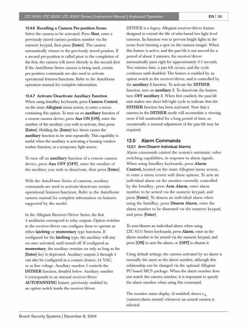
EN | 36
Bosch Security Systems | December 8, 2004
LTC 8100, LTC 8200, LTC 8300 Series | Instruction Manual | Keyboard Operation
12.4.6 Recalling a Camera Pre-position SceneSelect the camera to be activated. Press Shot, enter apreviously stored camera position number via thenumeric keypad, then press [Enter]. The cameraautomatically returns to the previously stored position. Ifa second pre-position is called prior to the completion ofthe first, the camera will move directly to the second shot.If the AutoDome Series camera is being used, certain pre-position commands are also used to activateoperational features/functions. Refer to the AutoDomeoperation manual for complete information.
12.4.7 Activate/Deactivate Auxiliary FunctionWhen using IntuiKey keyboards, press Camera Control,on the main Allegiant menu screen, to enter a menucontaining this option. To turn on an auxiliary function ofa remote camera device, press Aux ON [ON], enter thenumber of the auxiliary you wish to activate, then press[Enter]. Holding the [Enter] key down causes theauxiliary function to be sent repeatedly. This capability isuseful when the auxiliary is activating a housing windowwasher function, or a temporary light source.
To turn off an auxiliary function of a remote cameradevice, press Aux OFF [OFF], enter the number ofthe auxiliary you wish to deactivate, then press [Enter].
With the AutoDome Series of cameras, auxiliarycommands are used to activate/deactivate certainoperational features/functions. Refer to the AutoDomecamera manual for complete information on featuressupported by the model.
In the Allegiant Receiver/Driver Series, the first 4 auxiliaries correspond to relay outputs. Option switchesin the receiver/driver can configure these to operate aseither latching or momentary type functions. Ifconfigured for the latching type, the auxiliary will stayon once activated, until turned off. If configured asmomentary, the auxiliary remains on only as long as the[Enter] key is depressed. Auxiliary outputs 2 through 4can also be configured as a contact closure, 24 VAC, or as line voltage. Auxiliary number 5 controls theDITHER function, detailed below. Auxiliary number 6 corresponds to an internal receiver/driverAUTOPANNING feature, previously enabled by an option switch inside the receiver/driver.
DITHER is a legacy Allegiant receiver/driver featuredesigned to extend the life of tube-based low-light levelcameras. Its function was to prevent bright lights in thescene from burning a spot on the camera imager. Whenthis feature is active, and the pan/tilt is not moved for aperiod of about 2 minutes, the receiver/driverautomatically pans right for approximately 0.5 seconds.Two minutes later, a pan left occurs, and the cyclecontinues until disabled. The feature is enabled by anoption switch in the receiver/driver, and is controlled bythe auxiliary 5 function. To activate the DITHERfunction, turn on auxiliary 5. To deactivate the feature,turn OFF auxiliary 5. When first enabled, the pan/tiltunit makes one short left/right cycle to indicate that theDITHER function has been activated. Note that acamera in the DITHER mode will accumulate a viewingerror if left unattended for a long period of time, sooccasionally a manual adjustment of the pan/tilt may berequired.
12.5 Alarm Commands12.5.1 Arm/Disarm Individual AlarmsAlarm commands control the system's automatic videoswitching capabilities, in response to alarm signals.When using IntuiKey keyboards, press AlarmControl, located on the main Allegiant menu screen,to enter a menu screen with these options. To arm anindividual alarm on the monitor currently controlledby the IntuiKey, press Arm Alarm, enter alarmnumber to be armed via the numeric keypad, andpress [Enter]. To disarm an individual alarm whenusing the IntuiKey, press Disarm Alarm, enter thealarm number to be disarmed via the numeric keypad,and press [Enter].
To arm/disarm an individual alarm when using LTC 8555 Series keyboards, press Alarm, enter in thealarm number to be armed via the numeric keypad, andpress [ON] to arm the alarm, or [OFF] to disarm it.
Using default settings, the camera activated by an alarm isnormally the same as the alarm number, although thisrelationship can be changed via the optional AllegiantPC-based MCS package. When the alarm number doesnot match the camera number, it is important to specifythe alarm number when using this command.
The monitor status display (if enabled) shows CA
(camera/alarm armed) whenever an armed camera isselected.

EN | 37
Bosch Security Systems | December 8, 2004
LTC 8100, LTC 8200, LTC 8300 Series | Instruction Manual | Keyboard Operation
12.5.2 Arm/Disarm All AlarmsPress Alarm Control, located on the main Allegiantmenu screen to enter the menu screen containing theseoptions.
When using the IntuiKey: • To arm all alarms on the monitor currently
controlled, press Arm All Alarms.
• To disarm all alarms, press Disarm All Alarms.
When using LTC 8555 Series keyboards:• To arm all alarms, press User, Alarm, and then
[ON].
• To disarm all alarms, press [OFF].
12.5.3 Arm/Disarm MonitorWhen using IntuiKey keyboards:
• Press Alarm Control, located on the mainAllegiant menu screen to enter the screen withthese options.
• To arm the monitor currently controlled, pressArm Monitor.
• To disarm the monitor, press Disarm Monitor.
When using the LTC 8555 Series:• To arm the monitor, press User, Monitor, then
[ON] to arm all alarms.
• To disarm all alarms, press [OFF].
NOTE: Alarm video will appear on a monitor only if themonitor is armed and the alarm is armed for thatmonitor. The monitor status display (if enabled) will showa MA (monitor armed).
12.5.4 Alarms AcknowledgementBell [Ack] is provided so system operators can respondto alarms from the keyboard. Pressing Bell [Ack] whilethe keyboard is beeping (due to an alarm condition)always silences the beeper. Depending on alarmconfiguration programming, subsequent pressing of Bell[Ack] either clears alarm video from the monitors or hasno effect.
12.6 Sequence Control12.6.1 Load/Clear a SequenceTo load a previously programmed sequence to run onyour monitor, press Load Sequence [Seq], enter thedesired sequence number (1 to 60), then press [Enter].Note that loading a sequence does not automatically startthe sequence running.
Since sequences may be programmed to use more thanone monitor, all required monitors must be available. If asequence is already on a monitor, the operator wholoaded it originally (or an operator with a higher priority)is permitted to load a new sequence on the monitor(s).Others will receive an error message.
To clear a monitor sequence, press Load sequence[Seq], then press [Enter]. Only the operator whooriginally loaded it (or an operator with a higher priority)is permitted to clear a monitor sequence. Others willreceive an error message.
If enabled, the status display area of the monitor indicatesthe sequence number in the appropriate location. If nosequence is currently loaded, 00 is displayed.
12.6.2 Run a SequenceTo run a sequence currently loaded on a monitor, pressStart Sequence [Run]. If the sequence was stopped, thecommand starts sequencing. Direction of the sequencingis indicated in the monitor status display (if enabled), by adirectional arrow and the letter R to the right of thesequence number. If Start Sequence [Run] is pressedwhile a sequence is already running, the switcher goesimmediately to the next step in the sequence. Holdingdown Start Sequence [Run] produces a quick-scaneffect. If Start Sequence [Run] is depressed when nosequence is loaded, an error results. If the monitor is inalarm, Start Sequence [Run] controls switching of alarmvideo rather than a loaded sequence.
12.6.3 Stop a Running SequenceTo stop a sequence that is currently running, press HoldSequence [Hold]. The monitor status display now showsa S to the right of the sequence number. If the sequenceis already stopped, pressing Hold Sequence [Hold] hasno effect. If no sequence is currently loaded, pressingHold Sequence [Hold] results in an error condition. Ifthe monitor is in alarm, Hold Sequence [Hold] stops thealarm switcher rather than a loaded sequence.
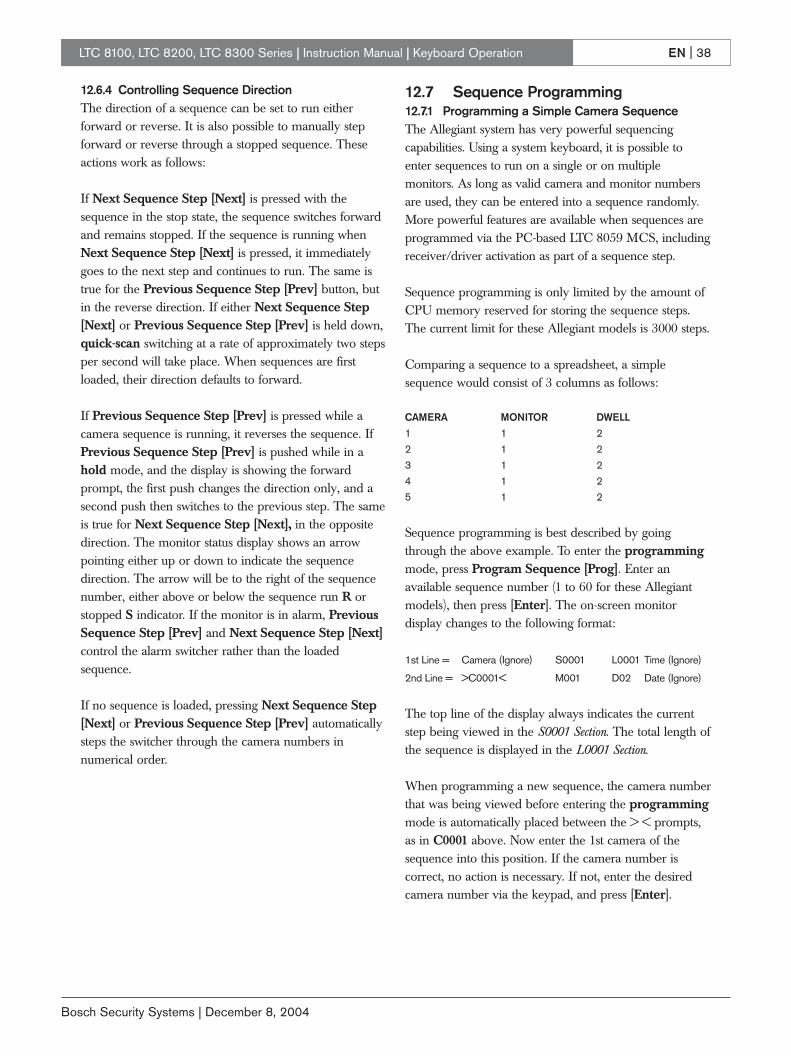
EN | 38
Bosch Security Systems | December 8, 2004
LTC 8100, LTC 8200, LTC 8300 Series | Instruction Manual | Keyboard Operation
12.6.4 Controlling Sequence Direction The direction of a sequence can be set to run eitherforward or reverse. It is also possible to manually stepforward or reverse through a stopped sequence. Theseactions work as follows:
If Next Sequence Step [Next] is pressed with thesequence in the stop state, the sequence switches forwardand remains stopped. If the sequence is running whenNext Sequence Step [Next] is pressed, it immediatelygoes to the next step and continues to run. The same istrue for the Previous Sequence Step [Prev] button, butin the reverse direction. If either Next Sequence Step[Next] or Previous Sequence Step [Prev] is held down,quick-scan switching at a rate of approximately two stepsper second will take place. When sequences are firstloaded, their direction defaults to forward.
If Previous Sequence Step [Prev] is pressed while acamera sequence is running, it reverses the sequence. IfPrevious Sequence Step [Prev] is pushed while in ahold mode, and the display is showing the forwardprompt, the first push changes the direction only, and asecond push then switches to the previous step. The sameis true for Next Sequence Step [Next], in the oppositedirection. The monitor status display shows an arrowpointing either up or down to indicate the sequencedirection. The arrow will be to the right of the sequencenumber, either above or below the sequence run R orstopped S indicator. If the monitor is in alarm, PreviousSequence Step [Prev] and Next Sequence Step [Next]control the alarm switcher rather than the loadedsequence.
If no sequence is loaded, pressing Next Sequence Step[Next] or Previous Sequence Step [Prev] automaticallysteps the switcher through the camera numbers innumerical order.
12.7 Sequence Programming12.7.1 Programming a Simple Camera SequenceThe Allegiant system has very powerful sequencingcapabilities. Using a system keyboard, it is possible toenter sequences to run on a single or on multiplemonitors. As long as valid camera and monitor numbersare used, they can be entered into a sequence randomly.More powerful features are available when sequences areprogrammed via the PC-based LTC 8059 MCS, includingreceiver/driver activation as part of a sequence step.
Sequence programming is only limited by the amount ofCPU memory reserved for storing the sequence steps.The current limit for these Allegiant models is 3000 steps.
Comparing a sequence to a spreadsheet, a simplesequence would consist of 3 columns as follows:
CAMERA MONITOR DWELL1 1 22 1 23 1 24 1 25 1 2
Sequence programming is best described by goingthrough the above example. To enter the programmingmode, press Program Sequence [Prog]. Enter anavailable sequence number (1 to 60 for these Allegiantmodels), then press [Enter]. The on-screen monitordisplay changes to the following format:
1st Line = Camera (Ignore) S0001 L0001 Time (Ignore)
2nd Line = >C0001< M001 D02 Date (Ignore)
The top line of the display always indicates the currentstep being viewed in the S0001 Section. The total length ofthe sequence is displayed in the L0001 Section.
When programming a new sequence, the camera numberthat was being viewed before entering the programmingmode is automatically placed between the > < prompts,as in C0001 above. Now enter the 1st camera of thesequence into this position. If the camera number iscorrect, no action is necessary. If not, enter the desiredcamera number via the keypad, and press [Enter].

EN | 39
Bosch Security Systems | December 8, 2004
LTC 8100, LTC 8200, LTC 8300 Series | Instruction Manual | Keyboard Operation
Using the joystick, move RIGHT one step. The promptswill shift over to the monitor number shown in theexample as M001. The monitor that was being controlledby the keyboard before entering the programmingmode is defaulted to this position. If correct, no action isnecessary. If not, enter the desired monitor number viathe keypad, and press [Enter].
Move RIGHT again. The prompts now shift over to thedwell time shown in the example as D02. The defaultdwell time for a new sequence is always 2 seconds. If adifferent dwell period is desired, change the value to anynumber between 1 and 60. One line is now complete.
Press Next Step [Next] to add a second line. The cameranumber automatically increments, while the monitornumber and dwell remain the same as the first line. Sincethis line is correct, no change is necessary and Next Step[Next] may be pressed 3 more times until line 5 isreached. The joystick can be used to move around withinthe spreadsheet, but only the Next Step [Next] key canadd new lines.
Continue entering camera, monitor, and dwell times inthis fashion, until finished.
If you only want to store the sequence for future use andthen exit the programming mode, press Exit / Save[Prog]. Press Exit / Run [Run], to exit theprogramming mode, store the sequence into memory,and start the sequence running. The switcher stepsthrough the 5 steps in the order shown, and repeats thesequence when it reaches the last step. To program asequence to run once through all its steps and then stop,enter the value 62 for the dwell time in the last step andpress [Enter]. The dwell display will change to STP,meaning stop. To program a sequence to run oncethrough all its steps and then unload itself, enter the value63 for the dwell time in the last step, and press [Enter].The dwell display will change to ULD, meaning unload.
To edit an existing sequence, press Program Sequence[Prog], enter the existing sequence number, then press[Enter]. You can insert a line into a sequence bynavigating down to the line where inserting a new line,and press Insert Step [ON]. A new line identical to theone you are on is added to the next step. To delete a step,navigate to the line to be deleted, and press DeleteCurrent Step [OFF]. To delete all steps below the lineyou are viewing, press Delete From Here To End[Lock]. (Be careful with this feature!)
It is also possible to erase a sequence: Press Delete From Here To End [Lock] while on thefirst line of the sequence. Then press Delete CurrentStep [OFF]. The sequence will be erased, and theprogramming mode is automatically exited.
12.7.2 Programming a SalvoSwitching Camera Sequence
A SalvoSwitching sequence can be used to switch a groupof monitors simultaneously as a synchronized group. Toprogram a Salvo sequence, enter the programmingmode as described above for a simple camera sequence.By definition, Salvo sequencing involve more than onemonitor. An example of a simple Salvo sequence thatswitches cameras on three monitors simutaneously isshown below:
CAMERA MONITOR DWELL1 1 SLV2 2 SLV3 3 27 1 SLV8 2 SLV9 3 221 1 SLV22 3 SLV23 3 2
In general, follow the instructions used for the simplecamera sequence (described above), but instead ofentering a number of seconds for steps that must switchinstantly, enter 61 and press [Enter]. This causes theswitcher to automatically change to the salvo abbreviationSLV. Dwell time (in seconds) is entered only when youreach the step containing the last monitor that will beswitched within the synchronized group.

EN | 40
Bosch Security Systems | December 8, 2004
LTC 8100, LTC 8200, LTC 8300 Series | Instruction Manual | Keyboard User Functions
13.0 KEYBOARD USER FUNCTIONS
13.1 GeneralUser functions are keyboard operations which are usedinfrequently, but provide important system options. Thesefunctions are listed below.
NOTE: Certain functions are restricted to certain userpriority levels. Information on user priority levels can befound in Section 10, USER INFORMATION. To executethese user functions, select the desired function, andfollow the steps below.
For IntuiKey Keyboards:1. From the main Allegiant screen, press User
Functions (softkey).
2. Use Previous or Next to navigate to the desiredfunction.
3. Press the desired softkey.
For LTC 8555 Series Keyboards:1. Press USER and verify the indicator lights.
2. Using the numeric keypad, enter the desired userfunction number.
3. Press [Enter]. Note that the keyboard cameradisplay shows F followed by the selected functionnumber.
4. Follow the directions for the specific user function(described in its section, herein). In many cases,the joystick is used to select options
5. Press USER to exit back to normal mode.
EXAMPLE: USER 2 ENTERThe above example accesses User Function #2 asdescribed in THIS SECTION.

EN | 41
Bosch Security Systems | December 8, 2004
LTC 8100, LTC 8200, LTC 8300 Series | Instruction Manual | Keyboard User Functions
Joystick Joystick Access LevelFn# Up/Down Left/Right Function Description 1 2-7 8
1 n/a n/a Local keyboard test Y Y Y2 n/a n/a Show keyboard port number Y Y Y3 n/a n/a Select keyboard beeper ON/OFF Y Y Y4 Up/Down Left/Right Adjust position of monitor display Y Y N5 Brightness Msg vs. Stat Monitor display brightness / status selection Y Y N6 Time/Date ON/OFF Overlay ON/OFF Select monitor display option Y Y N7 Set Select Set time Y Y N8 Set Select Set date Y Y N9 Set Select Set camera ID Y N N
10 n/a n/a Change user password Y Y Y11 Select n/a Select time/date format Y N N12 n/a n/a Default all monitor overlays Y N N13 Select n/a Print configuration tables to system printer Y N N14 n/a n/a Reserved — — —15 n/a n/a Reset system (password required) Y N N16 Select Enable/Disable Time event enable/disable Y N N17 Set Select Set monitor ID Y N N18 Select n/a Print sequence Y N N19 Select n/a Select alarm response (password req’d) Y N N20 Select n/a Select printer verbosity Y N N21 Select n/a Designate alarm monitor type (password) Y N N22 Select n/a Select control code format (fixed/variable) Y N N23 n/a n/a Display CPU software version number Y Y Y24 Up/Down Left/Right Set positions on all monitor displays Y Y N25 Brightness Msg vs. Stat Set brightness on all monitor displays Y Y N26 Time/Date Overlay Set display option on all monitors Y Y N27 Keyboard Login Select Select keyboard login Y N N28 Console Login Select Select console login Y N N29 Default Parameters Select Default RS-232 parameters Y N N30 Console Parameters Select Set console RS-232 parameters Y N N31 Printer Parameters Select Set printer RS-232 parameters (LTC 8300 only) Y N N32 n/a n/a Reserved — — —33 n/a n/a Display user number and priority Y Y Y34 Select n/a Camera indicator Y N N35 Camera No. Enable/Disable Controllable cameras Y N N36 Select Enable/Disable Select crosspoint data Y N N37 Select n/a R/D addresses mode Y N N38 Select n/a Printer port mode Y N N39 Select n/a Select DIU interface port Y N N40 n/a n/a Vertical sync adjust Y N N41 Select n/a Cache remote Cameras Y N N42 Select n/a Keyboard login auto-off mode Y N N43 n/a n/a CPU battery status Y Y Y99 Select n/a Use functions index Y Y Y

EN | 42
Bosch Security Systems | December 8, 2004
13.1.2 User Function 1 - Local Keyboard Test
User Function 1 can be used as a local test to ensurethat all the keyboard LEDs and switches are working.This function automatically calibrates the center positionof the analog joystick on LTC 8555 keyboards. Uponentering this test, the keyboard will beep and all LEDswill light for about two seconds. The USER should noteif there are any LED failures.
Each key may be pressed to display a unique codenumber associated with that key. Follow the TABLEbelow to ensure that all keys are properly beingprocessed by the keyboard. Push USER last, as thiscauses the keyboard to exit the test mode.If the logon system feature has been selected by thesystem installer, the same local test may be initiated while the keyboard is not ON LINE by pressing *.
1Keyboard tests show a speed indicator value in the first digit positionwhen performing pan, tilt, or zoom actions.
13.1.3 User Function 2 - Show Keyboard Port Number
User Function 2 may be used to identify which port a keyboard is plugged into. After entering User Function 2, read the keyboard port number from the monitor display on the keyboard. If using the LTC 8555 Series keyboard, press [User] to exit.
13.1.4 User Function 3 - Select Keyboard Beeper ON/OFF
When User Function 3 is selected, the keyboard usermay enable/disable the keyboard audio beeper. Ifusing the LTC 8555 Series keyboard, press [ON] toenable the beeper or [OFF] to disable it. Press [User]to exit. Upon power up of the keyboard and wheneverthe Allegiant system undergoes a reset, this setting isset to [ON].
13.1.5 User Function 4 - Adjust Position of Monitor Overlay
User Function 4 allows the characters on the videomonitor display to be positioned from the keyboard.Only the display on the monitor that the keyboard iscurrently connected to is effected.
If using the LTC 8555 Series keyboard, use the joystickto position the display as required. Press [Enter] tostore the position. Press [User] to exit.
13.1.6 User Function 5 - Monitor Display Brightness / Status Selection
The white portion of the characters on the videomonitor display may be made brighter or dimmer bythe User Function 5. Only the display on the monitorthat the keyboard is currently connected to is effected.After entering the mode, there are four possiblesettings. If using the LTC 8555 Series keyboard, movingthe joystick up increases the brightness, and moving itdown decreases the brightness.
The User Function 5 also permits selection of eitherthe status display or a 12-character monitor messageto appear in the first line of the monitor display. Thestatus display indicates alarm, sequence, and lockoutinformation regarding the monitor. The monitormessage is a stationary display. This means the displaywill not change as video is switched from camera tocamera on the monitor. After entering the mode, movethe joystick left to select monitor message format, andright to select status format. If using LTC 8555 Serieskeyboard, to exit the mode, press [User].
LTC 8100, LTC 8200, LTC 8300 Series | Instruction Manual | Keyboard User Functions
Key No.IRIS UP 044IRIS DOWN 045FOCUS UP 042FOCUS DOWN 043ZOOM CLOCKWISE1 041ZOOM COUNTER1 040CLOCKWISEALARM 004USER 000SEQUENCE 032HOLD 036RUN 033PREVIOUS 035NEXT 034#1 010#2 018#3 026#4 011#5 019#6 027
Key No.CAMERA 024MONITOR 008ACKNOWLEDGE 005PROGRAM 002SET 001SHOT 009OFF 025ON 017* 016LOCK 003#7 012#8 020#9 028CLEAR 037#0 013ENTER1 029UP1 052RIGHT1 051DOWN1 050LEFT1 053

EN | 43
Bosch Security Systems | December 8, 2004
LTC 8100, LTC 8200, LTC 8300 Series | Instruction Manual | Keyboard User Functions
13.1.7 User Function 6 - Select Monitor Display Option
User Function 6 allows the user to remove the timeand date (the left side of the display), or the entiredisplay from the individual monitor. If using the LTC 8555 Series keyboard, move the joystick down toblank the time and date from the screen. This issometimes desirable when a VCR with its own timeand date is being used. Move the joystick up to addthe time and date back.
Move the joystick left to blank the left side portion ofthe display from the monitor, and right to return it.Refer to User Function 5 to verify brightness level.Press [User] to exit the mode.
13.1.8 User Function 7 - Set Time
User Function 7 enables operator setting of the timedisplayed on all system monitors. After entering themode, use the joystick select hours, minutes, or secondsin an edit line (displayed on the monitor screen). Ifusing the LTC 8555 Series keyboard, moving thejoystick up or down counts the data item up or down;moving right or left selects between data items. NEXTis used to set the seconds to zero. If NEXT is pressedwhen the seconds are over 30, the minute count(shown on the operating clock display) is incremented.If NEXT is pressed when the seconds are under 30,the minutes are left unaffected. Press [Enter] to updatethe time displayed on all system monitors, and press[User] to exit the mode.
13.1.9 User Function 8 - Set Date
User Function 8 enables the operator to set the datedisplayed on all system monitors. If using the LTC 8555Series keyboard, the joystick is used to select the day,month, or year in an edit line (displayed on the monitorscreen). Move the joystick up or down to count the dataitem up or down; move right or left selects between thedata items. If using the LTC 8555 Series keyboard, press[Enter] to update the date displayed on all systemmonitors. Press [User] to exit the mode.
13.1.10 User Function 9 - Set Camera ID
User Function 9 permits entry of a 16-charactercamera identification message. This message appearson the video monitor display whenever the specificcamera is called up for viewing. If desired, thismessage can be used to identify the particular scenebeing viewed. Refer to Section 15, the CHARACTER ROM
TABLES for the various characters available. Afterentering the mode, users with priority level 1 can usethe joystick to move right or left to select the characterto be changed. The selected character will be identifiedby a box with a question mark inside it. The first lineof the video monitor screen indicates the code numberof the character selected. Move the joystick up ordown to step through the Character ROM table, orenter the character’s number (as identified in thetables) via the numeric keypad, and press [Enter].Once the title has been set, press [Enter] to store it tomemory. If using the LTC 8555 Series keyboard, press[User] to exit the mode.
13.1.11 User Function 10 - Change USER Password
User Function 10 allows an operator to change systemaccess passwords. This feature is only required insystems where the system installer has enabledkeyboard login and the password security feature.After entering the mode, the video monitor displayprompts for the current password OLD PASSWORD.Enter the current user password via the numerickeypad, and press [Enter]. If the system does notaccept the old password, the system reamins at thisprompt. If the entered password is valid, the displaychanges to the NEW PASSWORD prompt for entryof the new password (up to 6 numerals) via thenumeric keypad, then press [Enter]. Leave this stepblank if no password is desired. If none is used, atlogon, press [Enter] at the P prompt. To safeguardagainst typographical errors, the system promptsVERIFY PASSWORD requiring reentry of the newpassword. If the entered passwords do not agree, thesystem prompts for reentry and verification of the newpassword. If the two password entries agree, the videomonitor prompt indicates PASSWORD UPDATED.Press [User] to exit the mode.
13.1.12 User Function 11 - Select Time / Date Format
User Function 11 can be used by priority level 1 toselect time and date format used throughout thesystem. The 2 formats of time available are - 12-hourmode and 24-hour mode. The date is available in aMM-DD-YY format (U.S.), a DD-MM-YY format(Int’l), and a YY-MM-DD format (Asian). Afterentering the mode, move the joystick up or down toselect the desired format. If using the LTC 8555 Serieskeyboard, press [Enter] to convert the system to theformat chosen, then press [User] to exit the mode.

EN | 44
Bosch Security Systems | December 8, 2004
LTC 8100, LTC 8200, LTC 8300 Series | Instruction Manual | Keyboard User Functions
13.1.13 User Function 12 - Default All Monitor Overlays
User Function 12 can be used by users with thepriority level 1, to reset all monitor overlays to defaultcharacteristics; bottom center of screen, and fullbrightness. After entering the mode, press [Enter] toreset all monitor overlays. If using the LTC 8555 Serieskeyboard, press [User] to exit.
13.1.14 User Function 13 - Print System Configuration Tables
Users with priority level 1 can use this function to printthe contents of the various tables programmed. Movethe joystick up and down to select a table, then press[Enter] to send it to the printer port. If using the LTC 8555 Series keyboard, press [User] to exit.
13.1.15 User Function 14 - Reserved Function
13.1.16 User Function 15 - System Reset
The system may be reset from the keyboard by userswith priority level 1. After entering this mode, thevideo monitor screen indicates RESET SYSTEM.Enter the password via the numeric keypad, and press [Enter]. The system will then reset. If using the LTC 8555 Series keyboard, press [User] to exit themode without resetting the system.
NOTE: The system should be reset whenever a changeis made on the main CPU module’s DIP switches.
Alternatively, the main power to the CPU bay may beswitched off for 10 seconds, then restored. Dependingon the size and complexity of the system, severalseconds may be required before operation is restored.This time is due to the amount of initialization tasksbeing performed, and is considered normal.
13.1.17 User Function 16 - Time Event Enable/Disable
Users with priority level 1 can use this function toenable or disable any of the programmed time eventfunctions. Up to 64 time event functions can beprogrammed with the optional LTC 8059/00 MCS forWindows, or the LTC 8850/00 GUI software. Movingthe joystick up and down steps through a table of the64 time events. If an event has been programmed,moving the joystick to the right enables the event, andto the left disables it. The current status of an enabledtime event is displayed by this user function.
13.1.18 User Function 17 - Set Monitor ID
User Function 17 can be used by users with thepriority level 1, to enter a (12-character) monitoridentification message for display in the top line of themonitor overlay display on any system monitor(s).This monitor title will be visible on the displayregardless of the camera currently being viewed. Thismessage can be used to identify the particular monitoror a group of cameras assigned to this monitor. Referto Section 15, CHARACTER ROM TABLES, for theavailable characters. After entering the mode, thejoystick is moved right or left to select the character tobe changed. The selected character is identified by abox with a question mark inside it. The first line of thevideo monitor display indicates the code number of thecharacter selected. Move the joystick up or down tostep through the Character ROM Table, or enter thecharacter’s number identified in the Tables via thenumeric keypad, then press [Enter]. Once the monitortitle has been set, press [Enter] to store it to memory. If using the LTC 8555 Series keyboard, press [User]to exit the mode. The user may select between thismonitor message and the status display by using the User 5 Function described above.
13.1.19 User Function 18 - Print Sequence
Use this function to print the contents of aprogrammed sequence. Users with priority level 1 canuse the joystick to select the desired sequence, thenpress [Enter] to print it to the printer port. Only thosesequences currently existing in memory will be shownin the list. If using the LTC 8555 Series keyboard, press[User] to exit.
13.1.20 User Function 19 - Select Alarm Response
Users with the priority level 1 can use this function toreset the system alarm configuration tables to one ofthese predefined alarm response modes: BASIC,AUTOBUILD, or SEQUENCE & DISPLAY. Movethe joystick up or down to select the desired mode,then enter your user password on the numeric keypad,and press [Enter] to update the alarm system. If usingthe LTC 8555 Series keyboard, press [User] to exit.

EN | 45
Bosch Security Systems | December 8, 2004
LTC 8100, LTC 8200, LTC 8300 Series | Instruction Manual | Keyboard User Functions
13.1.21 User Function 20 - Select Printer Verbosity
Priority level 1 users can use this function to selectbetween print modes; Limited Printing and FullPrinting. This selection determines the amount ofinformation printed during alarm processing. Bothmodes print alarm activation and deactivationmessages, but Full Printing goes into much moredetail. Use the joystick to select the desired mode, thenpress [Enter]. If using the LTC 8555 Series keyboard,press [User] to exit without changing the print mode.
13.1.22 User Function 21 - Designate Alarm Monitor Type
Priority level 1 users can use this function to designatethe monitor currently controlled by the keyboard aseither a STEP monitor or a REVIEW monitor. Thisfunction can only be used in the predefinedSEQUENCE & DISPLAY alarm response mode (seeSection 11, ALARM INFORMATION) to select whichmonitor is the STEP (also called SEQUENCE)monitor, and which is the REVIEW (also calledDISPLAY or CONTROL) monitor. To designate amonitor as the STEP or REVIEW monitor, enter User Function 21, then move the joystick up or downto select the monitor type. Enter your password on thekeyboard and press [Enter]. If using the LTC 8555Series keyboard, press [User] to exit. After selectingnew STEP and REVIEW monitors, the previous onesmay be disarmed (see Setion 12.5.3, Arm/Disarm Monitorinstructions).
13.1.23 User Function 22 -Select Control Code Format
This function designates whether variable speedpan/tilt and zoom commands are enabled (FactoryDefault Setting). In most cases, there is no need todisable this function. If it becomes necessary to enableor disable variable speed operation, users with prioritylevel 1 have this capability. Move the joystick up ordown to select the desired setting, then press [Enter]. Ifusing the LTC 8555 Series keyboard, press [User] toexit.
13.1.24 User Function 23 - Display CPU Software Version Number
Users can use this function to display the revisionnumber of the Allegiant’s CPU software on themonitor screen.
13.1.25 User Function 24 - Set Positions on All Monitor Displays
This function is similar to User Function 4, except itchanges the monitor display positions of all monitorsin the system.
After entering User Function 24, use the joystick toposition the display as required on the monitorcontrolled by the keyboard. Press [Enter] to store andchange all system monitor displays to this position. Ifusing the LTC 8555 Series keyboard, press [User] to exit.
13.1.26 User Function 25 - Set Brightness on All Monitor Displays
This function is similar to User Function 5, except itchanges the monitor display brightness of all monitorsin the system.
The white portion of the characters on the videomonitor displays may be made brighter or dimmer viathe User Function 25. Move the joystick up toincrease brightness, or down to decrease brightness.Once the display on the monitor that the keyboard iscurrently controlling is adjusted, press [Enter] tochange all system monitors to the same setting. Press[User] to exit the mode.
The User Function 25 mode can also select either thestatus display or a 12-character monitor message toappear in the first line of the monitor display. Thestatus display indicates alarm, sequence, and lockoutinformation regarding the monitor. The monitormessage is a stationary display; the display will notchange as video is switched from camera to camera onthe monitor. After entering the mode, move thejoystick left to select the monitor message format, orright to select the status format on the monitor thekeyboard is controlling. Press [Enter] to change allsystem monitors to the same setting. If using the LTC 8555 Series keyboard, press [User] to exit.
13.1.27 User Function 26 - Set Display Option On All Monitors
This function is similar to User Function 6, except itselects the monitor display option of all monitors inthe system. The User Function 26 mode allowsremoval of the time and date, the left side of thedisplay, or to remove the entire display from thesystem monitors. Move the joystick down to blank thetime and date from the screen. This is sometimesdesirable when a VCR with its own time and date isbeing used. Move the joystick up to add the time anddate back again.

EN | 46
Bosch Security Systems | December 8, 2004
LTC 8100, LTC 8200, LTC 8300 Series | Instruction Manual | Keyboard User Functions
Move the joystick left to blank the left side of thedisplay from the monitor and right to return it. Referto User Function 5 or 25 to verify brightness level.Press [Enter] to update all system monitors to theselected format. If using the LTC 8555 Series keyboard,press [User] to exit.
13.1.28 User Function 27 - Select Keyboard Login
This function controls the system’s keyboard loginfeature. Move the joystick up or down to select themode for the system to function in. If the login featureis enabled (MUST USE KBD PWD is selected), thesystem keyboards require each user to login and logoffthe system. All users are required to enter a usernumber and correct password to interact with thesystem. If the login feature is disabled (NO KBDPWD LOGIN is selected), system keyboards arealways online with the system.
Once selection is made, exit the User Function modeand reset the system either via keyboard User Function15, or by removing and restoring the main AC powerto the system. Once the system has been reset, thekeyboard login function will be active and all systemkeyboards will need to be logged in to access thesystem.
13.1.29 User Function 28 - Select Console Login
This function controls the system’s external Console port login feature. After entering the mode,move the joystick up or down to select the mode inwhich the system should function. If the login featureis enabled (MUST USE CON PWD is selected), anyexternal PC or other computing device will berequired to login to communicate with the system.External computing devices are required to enter auser number and correct password. If the Consolelogin feature is disabled (NO CON PWD LOGIN isselected), the Console port is available forcommunication.
Once the selection is made, exit the User Functionmode and reset the system, either via keyboard User Function 15 or by removing and restoring themain AC power to the system. Once the system hasbeen reset, the Console login function is active, andall external computing devices need to login to accessthe system.
13.1.30 User Function 29 - Reset RS-232 Parameters to Default
This function returns the system’s external RS-232 ports to a known default state. After enteringthe mode, enter a valid password. The system willreset after placing the RS-232 protocols back to thedefault state. Refer to the Section 9, FACTORYDEFAULT SETTINGS for additional information.
13.1.31 User Function 30 - Set Console RS-232 Parameters
Priority level 1 users can select the RS-232 baud rateand handshake options for the system’s Console port,via this function. Upon entry to this mode, the currentsettings are displayed. Move the joystick up/down toselect the baud rate, and left/right to select thehandshake option. After being changed, the port is also automatically set to eight data bits, no parity, andone stop bit. Once new settings have been selected,enter the user password and press [Enter]. If using the LTC 8555 Series keyboard, press [User] to exit.
13.1.32 User Function 31 - Set Printer RS-232 Parameters
Priority level 1 users can select the RS-232 baud rateand handshake options for the LTC 8300 system’sPrinter port, via this function. Upon entry to the mode,the current settings are displayed. Move the joystickup/down to select the baud rate, and left/right to selectthe handshake option. After being changed, the port isalso automatically set to eight data bits, no parity, andone stop bit. Once new settings have been selected,enter the user password and press [Enter]. If using theLTC 8555 Series keyboard, press [User] to exit.
13.1.33 User Function 32 - Reserved Function
13.1.34 User Function 33 - Display User Number and Priority
This function displays the current user’s number andpriority level on the monitor screen. The user numberwill be displayed on the top line and the user’s prioritylevel will be displayed on the bottom line of themonitor screen. If using the LTC 8555 Series keyboard,press [User] to exit.

EN | 47
Bosch Security Systems | December 8, 2004
LTC 8100, LTC 8200, LTC 8300 Series | Instruction Manual | Keyboard User Functions
13.1.35 User Function 34 - Camera Indicator
Priority 1 users can use this function to enable an on-screen indicator to identify a pan/tilt equipped camera.Move the joystick up or down to select DISP CAMCONTROL or NO CAM CONTL DISPL. Press[Enter] to activate your selection. When enabled,cameras identified as controllable (via User Function35 or the optional PC software package), show a ↔ inthe middle of the first line of monitor text.
13.1.36 User Function 35 - Controllable Cameras
Priority 1 users can use this function to select camerasites equipped with pan/tilt devices. Move the joystickup or down to select the camera number, and left orright to select FIXED or MOVABLE. User Function34 or the optional PC software package enables ordisables the display of the controllable cameraindicators on the system monitor displays.
13.1.37 User Function 36 - Select Crosspoint Data
Priority 1 users can use this function to select optionsfor accessory device data that can be sent out thebiphase control port. Move the joystick up or down toselect XPOINT DATA, ALARM XPOINT, orPHYSICAL CAMERA NUMBER, and left or rightto enable/disable the selected option. These optionsneed only be enabled when Switcher Followeraccessory devices are being used in the system.
13.1.38 User Function 37 - R/D Address Mode
Priority 1 users can use this function to select whetherthe biphase control data commands will be addressedusing the cameras’ logical numbers or physicalindexes in the camera table. Move the joystick up ordown to select LOGICAL or PHYSICAL and press[Enter] to activate your selection. If this option is setto LOGICAL, receiver/drivers should be addressedusing the cameras’ logical identification number. If it is set to PHYSICAL, receiver/drivers should beaddressed using the cameras’ physical number.
13.1.39 User Function 38 - Printer Port Mode (LTC 8300 Series only)
This function allows configuration of the system’sPRINTER port, for use with a Console Port Expanderaccessory device. Priority 1 users can move the joystick upor down to select the Printer port function; NORMAL orEXPANDED. Press [Enter] to activate your selection.You must reset the system for this setting to take effect.
13.1.40 User Function 39 – Select DIU Interface Port
Priority 1 users can use this function to select theswitcher’s interface port to be connected to an externalAllegiant Bilinx Data Interface unit accessory unit.Move the joystick up or down until the desired portfor use as a data interface (DIU) is displayed. Press[Enter] to configure the port. If using the LTC 8555keyboard, press [User] to exit the mode.
13.1.41 User Function 40 - Vertical Sync Adjust
Priority 1 users can use this function to synchronize thevertical switching action of the switcher to the cameracurrently selected on the monitor. Press either [NEXT]or [PREVIOUS] to synchronize the phase delay of thesystem to the camera signal. The system maytemporarily stop functioning for 1 or 2 seconds whilethe adjustment is being made. The current phase delaysetting will be displayed on the bottom line of themonitor text.
13.1.42 User Function 41 – Cache Remote Cameras
This function is only applicable to Allegiant Satellitesystems that employ a multi-level cascaded systemconfiguration. Priority 1 users can eliminate generationof repetitive Satellite commands (that could causeundesirable operation) by disabling the remote cameracache feature using this function. After entering themode, move the joystick up or down to select thedesired option. Enter a valid password, and press[Enter]. After a change is made, the system must bereset either via User Function 15 or by temporarilyremoving AC power to the unit.
13.1.43 User Function 42 – Keyboard Login Auto-off Mode
Priority 1 users can use this function to select a keyboardlogoff feature to automatically log a keyboard off after apreselected time of inactivity. After entering the mode,move the joystick up or down to select the desired timeperiod. Enter a valid password, and press [Enter]. If usingthe LTC 8555 keyboard, press [User] to exit the mode.
13.1.44 User Function 43 – CPU Battery Status
Use this function to view the condition of the batteriesused to backup CPU memory. Once the function isentered, the condition is displayed on the monitor textdisplay. If using the LTC 8555 keyboard, press [User] toexit the mode.

EN | 48
Bosch Security Systems | December 8, 2004
LTC 8100, LTC 8200, LTC 8300 Series | Instruction Manual | Maintenance Information
13.1.45 User Function 99 - User Function IndexThis function is an index listing of all Keyboard UserFunctions. Move the joystick up or down to view anabbreviated description of the function numbercurrently shown in the first line of the monitor display.
14.0 MAINTENANCE INFORMATIONTHE ALLEGIANT SYSTEM IS DESIGNED TOPERFORM FOR LONG PERIODS OF TIME WITH LITTLE OR NO MAINTENANCE.OCCASIONALLY, KEYBOARD CLEANING OR CPU BATTERY REPLACEMENT MAY BE NECESSARY. INSTRUCTIONS AREPROVIDED IN THIS SECTION.
14.1 Cleaning the Keyboard The keyboard may be cleaned when necessary, bytemporarily removing it from the system and wiping itwith a damp cloth. If a conventional spray cleaner isrequired, spray the cloth first, then wipe off the surfaces.Do not use petroleum-based cleaners or those containingbenzene, triclorethylene, ammonia or acetone, whichcould damage plastic surfaces.
14.2 Replacement of Memory Backup Batteries
The circuit board’s lithium batteries only require attentionwhen replacement is necessary. The batteries enableRAM memory to retain its contents for up to a yearwithout the unit being powered. Since these batteries arenot used while the AC power is on, several years ofservice should be expected before replacing them isnecessary.
When the batteries have reached the end of their usefullife, the Time and Date portion of on-screen monitordisplays alternate with ?? ?? ??. This display informs theuser that the CPU batteries must be replaced. The frontpanel of the unit must also provides LED indication of alow battery condition.
The memory backup batteries are located on the CPUmodule. Refer to the INSTALLATION PROCEDURE,Section 6 for information on removing the unit cover toaccess the CPU module.
The two batteries are mounted on the left edge of thecircuit board. Insert a small flat-blade screwdriver into theslot on one of the battery holder sockets and gently prythe battery from the holder until it can be removed byyour fingers. Replace the old battery with the new batteryby lifting the retaining clip up while inserting the batteryinto the socket. Ensure that the negative side of thebattery contacts the socket by seating the battery until it issomewhat flush with the battery holder. Repeat thisprocedure for the other battery.
Reprogramming of the system’s time and date andsequences must now be reentered. Other system-programmed data (camera titles, alarm configurations,user lockout data etc.), are stored in nonvolatile memory,and should be unaffected.

EN | 49
Bosch Security Systems | December 8, 2004
LTC 8100, LTC 8200, LTC 8300 Series | Instruction Manual | Character ROM Tables
15.0 CHARACTER ROM TABLES
(continued on next page)

EN | 50
Bosch Security Systems | December 8, 2004
LTC 8100, LTC 8200, LTC 8300 Series | Instruction Manual | Error Messages

EN | 51
Bosch Security Systems | December 8, 2004
LTC 8100, LTC 8200, LTC 8300 Series | Instruction Manual | Error Messages
16.0 ERROR MESSAGESError Description Error Description Error 01 - Invalid camera request
The camera number entered from thekeyboard does not exist. If using theoptional LTC 8059/00 MCS or the LTC 8850/00 GUI software, ensure thatthe number exists in the CameraIdentification table. Download the table tobe sure.
Error 20 - Acknowledge denied
ACKNOWLEDGE has beenpressed by a user without authorityto acknowledge alarms.
Error 02 - Invalid monitor request
The monitor number entered from thekeyboard does not exist. Enter a validmonitor number.
Error 21 - Incorrect acknowledge
To properly acknowledge an alarmevent, the keyboard must beswitched to a monitor that isdisplaying the alarms.
Error 03 - Locked remote device
The remote device requested cannot becontrolled because it is locked by a userwith equal or higher priority. Check withthe other users or request that a higherpriority user unlock the remote device.
Error 22 - Acknowledge disabled
Alarms on this monitor cannot beacknowledged because thatcapability has been disabled by thesystem programmer.
Error 04 - Monitor locked
The monitor requested cannot be accessedbecause it is locked by a user with equal orhigher priority. Check with the other usersor request that a higher priority userunlock the monitor.
Error 23 - Camera not in alarm
The camera displayed on themonitor is not an alarm video;only alarm-generated video can beacknowledged.
Error 05 - Remote device access restricted
Remote is locked out by Remote Lock Outtable.
Error 24 - Keyboard not enabled foracknowledge
This keyboard may notacknowledge alarm video on thismonitor; it has been disabled bythe system programmer.
Error 06 - Monitor accessrestricted
Monitor is locked out by Monitor LockOut Table.
Error 25 - Alarm switcher running
Alarm video may only beacknowledged if the alarm switcheris not running; press HOLD tostop the switcher.
Error 10 - Access denied
A function was requested that requires ahigher user priority. Only a Priority 2 useror a supervisor with Priority 1 may accessthis function.
Error 50 - SEQUENCE not available
Error 51 - SEQUENCE not available
The user tried to load a switchersequence that does not exist. Thisis a good way to tell from thekeyboard, which sequencenumbers are unused when desiringto add one.
A request was made to load anABSOLUTE sequence without thekeyboard being on one of themonitors in that sequence. Becauseinadvertent loading of monitorsshould be avoided, the user isrequired to switch his keyboard toone of the monitors used by thesequence. The PROGRAM modemay be used to review whichmonitors are used in the sequence.
Error 11 - Access denied
A function was requested for which youruser priority is too low. Only a supervisorwith Priority 1 may access this function.
Error 52 - SEQUENCE request
A request was made to load aRELATIVE sequence on amonitor number that is too high.The monitors used by thesequence would extend past thehighest monitor. Try switching to alower monitor number beforeloading the sequence.
Error 15 - Invalid user function
The function number requested from thekeyboard is invalid. Refer to the UserFunction table for a listing of the validuser function numbers.
Error 53 - Switcher empty
The user has tried to control asequence using NEXT, PREV,RUN, or HOLD without asequence having been loaded.

EN | 52
Bosch Security Systems | December 8, 2004
LTC 8100, LTC 8200, LTC 8300 Series | Instruction Manual | Error Messages
Error Description Error Description Error 55 - SEQUENCE priority
The switcher sequence being requested orcleared requires monitors that are in use bya user of equal or higher priority. Contact auser with higher priority, or have thesystem administrator clear the monitors inquestion.
Error 80 - Trunk not available
An attempt was made to access aremote camera connected to asatellite system, but no unusedtrunk lines are currently available.
Error 56 - SEQUENCE request
The user has tried to load a sequence thatis being edited in the PROGRAM mode.Once editing has been completed, thesequence may be loaded.
Error 81 - Satellite Trunk Siezed
The camera currently viewed haschanged because an operator witha higher priority has selected adifferent camera that seized thetrunk line from the satellite.
Error 58 - SEQUENCE request
The sequence being requested is a Relativesequence, and the user is only permittedaccess to Absolute sequences.
Error 89 - Internal stack error
A stack overflow has occurredwithin the system. Report this tothe manufacturer.
Error 60 - PROGRAM request
The user has tried to program a sequencethat is currently running. The sequencemust first be stopped before any editingcan be performed.
Error 90 - Keyboard entry undefined
The keyboard entry is not defined.Check the appropriate section ofthe instruction manual for thedesired operation and try again.
Error 62 - PROGRAM request
The user has tried to program a newsequence when the system is out ofsequence memory space. Delete unusedsequences and then program the newsequence.
Error 92 - Keyboard entry out ofrange
The data entered for a validcommand was not in the permittedrange. Check the appropriatesection of this instruction manualfor the acceptable ranges for thecommand in question and tryagain.
Error 63 - PROGRAM request
Some other user is already programming asequence on this monitor.
Error 94 - Keyboard entry invalid An invalid character has beenreceived from the keyboard,usually caused by acommunication error. Verify thatthe keyboard-to-system cable issecurely connected.
Error 70 - Monitor not allocatedto alarm monitorgroup
This monitor cannot be used for alarmoperations; it has not been designated asalarm-capable by the system programmer.
Error 95 - Keyboard entryincomplete
The control sequence sent from thekeyboard was incomplete, usuallyindicating a communication error.Verify that the keyboard-to-systemcable is not producing anintermittent connection.
Error 71 - Step monitor required
A group of alarm monitors may not havean armed Review (display) monitor withouthaving armed Step (sequence) monitors.
Error 96 - * (STAR) undefined The * key has been pressed, butthere is no definition for thisbutton.
Error 78 - Must enter alarmnumber
A specific alarm number must be enteredwhen arming or disarming an alarm.

EN | 53
Bosch Security Systems | December 8, 2004
LTC 8100, LTC 8200, LTC 8300 Series | Instruction Manual | Troubleshooting
17.0 TROUBLESHOOTING Allegiant systems are designed to perform reliably for long periods of time. All circuitry consists of state of the artcomponents designed around a single bay concept. If troubleshooting becomes necessary, follow these guidelines:
Problem Description/Solution
System CheckoutFront panel power LED is not lit. • Check the main AC supply source.
Green STATUS LED on front panel is not blinkingand BATTERY LED is off.
• Remove power from unit for 30 seconds. Apply power and verify that the STATUSLED is blinking. If still not functional, seek service.
• If Red BATTERY LED is lit, replace microprocessor board batteries. Followprocedure outlined in Maintenance Information Section.
Keyboard Checkout
No keyboard display indicators. • Check interconnect cable for cut or broken wires between the keyboard and themain bay and replace cable if necessary.
• Relocate keyboard connector on the bay to another keyboard input port.
• Replace keyboard.
Keyboard indicators lit but keyboard is inoperative. • Verify that the keyboard is loggedon to the system (if logon feature is enabled).
• Check interconnect cable for cut or broken wires between the keyboard and themain bay and replace cable if necessary.
• Relocate the keyboard connector on the bay to another keyboard input port.
• Replace the keyboard.
Limited keyboard functions. • If possible, perform local the keyboard test described in Section 13, KEYBOARDUSER FUNCTIONS to verify operation of all keys. If this local test cannot be performed,replace the keyboard.
• LTC 8059/00 MCS for Windows package users or LTC 8850/00 GUI softwareusers should refer to lockout tables to determine if the problem is related to userrestriction tables. If table settings are verified and no discrepancies are found,replace the keyboard.
Keyboard Joystick not centered. • If the analog joystick of the system keyboard becomes un-centered due to normalwear, it can be recalibrated. If using the IntuiKey keyboard, go to the KeyboardControl menu and press Joystick Auto Calibrate. If using the LTC 8555 Serieskeyboard, refer to User Function 1 procedure.
Video Monitor Display Checkout
No video display on any monitor. • Verify proper CPU operation as described above under System Checkout.
No video display on some monitors. • Verify that an operational camera is selected on suspect monitors.
• Confirm that the monitor is operational.
• Check the monitor coax connections.
• Verify that the coax connection is to the correct monitor output on the rear of thebay.
Poor video on monitor. • Check the monitor for proper termination.
• Check operation of a known good camera, directly to monitor.
Partial or no on-screen alphanumeric display. • Check user-selectable brightness feature (via User 5 Function) and then verify thatalphanumeric display has been enabled (via User 6 Function). Position the overlaywith User 4 Function.
Time and Date portion of the on-screen displayalternates with ?? ?? ??, and the LED on the frontpanel indicates a low battery condition.
• Replace CPU batteries.

EN | 54
Bosch Security Systems | December 8, 2004
LTC 8100, LTC 8200, LTC 8300 Series | Instruction Manual | Troubleshooting
Problem Description/Solution
Remote Receiver/Driver Functions Inoperative
All receiver/drivers and functions inoperative. • Verify that the CODE LED indicator on the front panel lights during P/T/Z controlactions. If not, the unit requires service.
Individual receiver/driver nonoperative. • Check the Green LED code indicator inside the receiver/driver box. If not lighting,check shielded twisted-pair cable between the unit and receiver/driver box.
• Confirm that the camera address setting in the receiver/driver corresponds to thecamera number selected by the keyboard.
• Perform internal receiver/driver local test to verify operation its receiver/drivercircuitry and the pan/tilt/zoom wiring.
AutoDome Series cameras are not operating in avariable speed fashion.
• Verify that CPU DIP switch 7 is selected for variable speed mode.
No Alarm Response
No system alarms are operative. • Verify that the Alarm LED on the front panel lights when the unit is in alarm. If not,verify that alarm programming is correctly enabled.
Individual cameras/monitors not responding whenalarmed.
• Ensure that the desired cameras are properly armed on the appropriate armedsystem monitors.
• Verify that the alarming device and the cable to the unit’s alarm interface connectionsare intact.
Incorrect system alarm response. • Verify that the desired alarm response mode has been selected.
• Refer to Section 13, KEYBOARD USER FUNCTIONS for instructions.
Alarms cannot be reset. • Power off/on unit to clear all alarms. (Any alarms that re-initiate are still active.)
• Verify alarm response and user settings for alarm acknowledge authority.
• Remove alarm connections to rear of unit. If alrams are still present, investigatepossibility that alarm input polarity has been changed by the installer using “CCL”commands.
CPU Software Version NumbersDuring the system evolution, new CPU softwareversions will be released. Some troubleshootingcases require Factory Technical Support personnelto ask for the version of the CPU. To obtain a CPUsoftware version:
• Using a system keyboard, an operator with a priority level 1 can enter keyboard User Function 23. Press [User], then Enter 23 using the numeric keypad, andpress [Enter].
• The CPU version number will be displayed on the overlay of the monitor currentlybeing controlled by the keyboard. Record this number for future reference.

EN | 55
Bosch Security Systems | December 8, 2004
LTC 8100, LTC 8200, LTC 8300 Series | Instruction Manual | Glossary of Terms
18.0 GLOSSARY OF TERMS
Term Definition
AUXILIARY An auxiliary is an additional function of the remote receiver/driver which permits on/off control of outputsavailable to the user. In the Allegiant system, four relay outputs are available, which can be configured forcontact closures, 24 VAC output, or LINE voltage output. Additionally they can also be set to activate eithermomentarily, or in a latching mode.
COMMAND SCRIPT A unique feature of the Allegiant system wherein a section of nonvolatile memory can be used to storespecialized factory programming. This program then provides custom features, not ordinarily obtainable.
DITHER A receiver/driver feature providing added protection to very low light level cameras, by periodically panninga few degrees left and right automatically.
LOCKOUTS Switcher/controller system ability to restrict access to certain system functions/features. The Allegiantsystem modes of lockouts are:
• By operator level, allowing a higher priority level operator to lockout lower level operators fromviewing or controlling specific cameras.
• By MCS setups to:
1. Restrict operators/keyboards from viewing/accessing any camera.
2. Restrict operators/keyboards from controlling/accessing any pan/tilt.
3. Restrict operators from using certain keyboards.
4. Restrict operators/keyboards from accessing certain monitors.
LOGON, LOGOFF A selectable Allegiant feature requiring operators to enter a User number and optional password into thekeyboard prior to access.
MATRIX SWITCHING The ability of a switching system to display any camera on any monitor, or the same camera on all monitors.
PHASED CAMERAS These are properly integrated cameras, giving a roll-free video display when switching from one camera tothe next in a sequential switcher system. Phased cameras are the result of line-locked cameras poweredfrom the same AC power, externally synchronized, or vertically phased adjusted on cameras equipped withthis option.
PRE-POSITION The ability to store the position of a pan/tilt/zoom lens, so that the desired scene can later be automaticallyrecalled. With the Allegiant system, there can be multiple preset scenes stored for each pan/tilt camera. Foreach scene, the pan, tilt, zoom, and focus settings are stored.
SalvoSwitching The ability of the Allegiant system to switch multiple video monitors as a synchronized group. Since multiplemonitors switch together, multiple scenes of an area or zone are viewable before switching to the next area.
SEQUENCE A series of camera scenes that can be preprogrammed to switch automatically. The Allegiant system canstore up to 60 sequences, each one capable of having random camera order, individual camera dwelltimes, and SalvoSwitching steps.
TIME EVENT An Allegiant system feature (available with the LTC 8059/00 MCS for Windows or the LTC 8850/00 GUIsoftware) enabling various system functions to periodically be activated automatically. Event functions(monitor message broadcasts, sequence and switching operations, receiver/driver actions, messageprinting, alarm settings, and execution of custom factory programming) can be stored in the system memoryfor execution at a predetermined time. The task can be specified to begin on a specific year, month, day,and time, and can repeat at intervals from every five minutes to a year.
VERTICAL INTERVAL
SWITCHING
Camera to camera video switching during the vertical blanking interval of the video signal. This minimizesvisual switching disturbances such as rolling, jitter, video flashes, etc., and eliminates frame information losswhen used with video tape machines.
VersAlarm A flexible system of configuring alarms via the optional LTC 8059/00 MCS for Windows or the LTC 8850/00 GUI software. Multiple groups of monitors can be programmed to respond to alarmconditions in various ways. Additionally, each alarm may call up 1 to 4 cameras with user-selectable remoteoperations. Alarm video may also be programmed to display user-defined alarm titles on the monitor overlaydisplay rather than the usual camera titles.

EN | 56
Bosch Security Systems | December 8, 2004
LTC 8100, LTC 8200, LTC 8300 Series | Instruction Manual | Appendix A - Satellite Systems
APPENDIX A - SATELLITE SYSTEMSA satellite system configuration is usually used for alarge distributed system, or to obtain extremely largematrix sizes configured more conventionally. Typically,a single Main control site can be used to view/controlcameras located both locally and at various remotesatellite sites. Since many satellite sites can be linked toa single Main control site, very large, distributedsystems can be achieved. If the satellite systems arelocated at the same site as the Main system, the resultis a large conventional-type system. In a satelliteconfiguration, the Main control site can view/controlany camera in the entire system, but the remotesatellite sites can only view/control cameras associatedwith their own site. Satellites may be configured tooperate either independently or, with no localviewing/control capability.
The Main site must consist of any Allegiant Seriesswitcher (LTC 8100, LTC 8200, LTC 8300, LTC 8500,LTC 8600, or LTC 8800). Satellite site switchers can beany Allegiant model switcher. A LTC 8780 Series DataConverter is required at each satellite site, to performaddress decoding and data conversion for theswitching system. If the satellite site containspan/tilt/zoom cameras, a LTC 8569 Code Merger isalso required at the satellite site. All products arestandard models, and the only required option is touse either the Master Control Software for WindowsLTC 8059/00 or the LTC 8850/00 GUI softwarepackage for initial programming of each Allegiantsystem.
Each satellite site must have an Allegiant control dataline from the code distribution unit at the Main site.This data line carries all pan/tilt/zoom controlcommands, in addition to the switching commandsgenerated by the Main site switcher. The control dataline should be connected to a LTC 8780 Series DataConverter to provide address decoding functions forthe satellite site. If operators at the satellite site arepermitted to control pan/tilt/zoom-equipped cameras,a LTC 8569 Series Code Merger must be installed atthe satellite site. The Code Merger combines codegenerated by the main site and the satellite site, soboth sites have control over pan/tilt/zoom-equippedcameras located at the satellite site. The LTC 8780Series unit can then be connected to one of the dataoutputs of the LTC 8569 Series unit.
One or more monitor outputs from each satellitesystem are used as trunk lines to link the remote sitesto the Main site. The number of trunk lines from asatellite site determines the maximum number ofcameras from that site that may be viewedsimultaneously at the Main site. A satellite switcher can provide only as many trunk lines as it has monitor outputs.
Sufficient monitor outputs used as trunk lines must beincluded in remote satellite switcher sites. The Mainsite switcher must include sufficient camera inputs forlocal cameras plus trunk lines. The maximum physicalnumber of camera inputs or monitor outputs used astrunk lines cannot exceed the capacity of the system.
A single Main site switcher can control multiplesatellite sites up to its video input limit. If full matrixswitching is required at the Main site, the number oftrunk lines from each satellite site must equal thenumber of monitors connected to the Main siteswitcher. Multiple independently controlled Main sitesystems can be combined to provide large numbers ofmonitor outputs at the Main site. System capacities arelisted below:
Max. Max. Max.System Camera Monitor No. ofType Inputs Outputs Satellite Sites
LTC 8100 Series 8 2 8
LTC 8200 Series 16 5 16
LTC 8300 Series 32 6 32
LTC 8500 Series 64 8 64
LTC 8600 Series 128 16 128
LTC 8800 Series 256 64 256
LTC 8900 4096 512 256

EN | 57
Bosch Security Systems | December 8, 2004
LTC 8100, LTC 8200, LTC 8300 Series | Instruction Manual | Appendix A Satellite Systems
Since Allegiant Series switchers can act as Main siteswitchers, they provide additional logical cameranumbers for identifying the location of the satellitecamera inputs in the system. These logical cameranumbers can also be used to provide titles whichwould appear on the Main site’s monitors for anyremote cameras. Since each camera (anywhere in thesystem) must have a unique camera number, logicalcamera numbers together with physical camera inputsmake up the total system camera capacity. Thus, thereis a trade-off between the total number of Main sitecameras and the number of inputs used as trunk lines.The more inputs used as trunk lines, the fewer thereare for use as direct camera inputs.
*Camera inputs at all sites, plus trunk lines.
The Main site system must be programmed via the Master Control Software for Windows LTC 8059/00 or the LTC 8850/00 GUI, to identifycamera trunk line inputs as well as remote satellitecameras. All systems must be configured with noduplicate camera numbers anywhere in the system.
Any alarm inputs to the Main site configured toactivate satellite cameras operate normally exceptwhen limited by the number of available trunk lines.The software automatically determines trunk usage,depending on the priority level of operators currentlyviewing satellite cameras. Alarm inputs applied at asatellite site will NOT activate alarm video at the Mainsite. If the application requires alarms located at asatellite to activate video at the Main site, the Mainsite’s LTC 8540/00 Alarm Interface unit must beremotely located. Multiple LTC 8540/00 AlarmInterfaces may be remoted via the LTC 8713 AlarmPort expander accessory, located at the Main switchersite in LTC 8800 and LTC 8900 systems. Up to 2 LTC 8540/00 Alarm Interfaces with a LTC 8713 AlarmPort Expander can be used in a LTC 8600 system.One LTC 8540/00 can be used in LTC 8500 systems.Since the LTC 8100, LTC 8200, and LTC 8300 Seriescontain an integral alarm interface, the remote alarminterface application does not apply.
A unique time and date synchronizing featureprovided in the Time Event table of the MCS forWindows or the GUI software may be programmedinto the Main site switcher. This permits periodicsynchronizing of the time and date to all switchers inthe system based on the Main site’s clock.
A conceptual diagram of a satellite switching system isfollows.
Model No. Maximum Number* System Cameras
LTC 8100 Series 264
LTC 8200 Series 272
LTC 8300 Series 288
LTC 8500 Series 320
LTC 8600 Series 1152
TC 8700 Series 2304
LTC 8800 Series 2304
LTC 8900 Series 4608

EN | 58
Bosch Security Systems | December 8, 2004
LTC 8100, LTC 8200, LTC 8300 Series | Instruction Manual | Appendix A Satellite Systems
Typical Local Monitors(Local Video Only)
BOSCH
BOSCH
Typical Fixed Cameras
Typical Controllable Camera
IntuiKey Keyboard(P/T/Z Control of Local Cameras Only)
1 2 3
4 5 6
7 8 9
0
Shot
MonProd
Clr
BOSCH
BOSCH
Typical LTC 8100, LTC 8200,or LTC 8300 Allegiant system
Biphase Data Lines to AllLocal P/T/Z Camera Sites
Video
Video
Video
Biphase Control + Satellite Data
Typical Alarm Input Contact
(For Local Alarms Only)
Typical Allegiant Satellite Site
Typical System Monitors(Local and/or Remote Video)
BOSCH BOSCHBOSCH
BOSCH
Typical Fixed Cameras
Typical Controllable Camera
Typical IntuiKey Keyboard
1 2 3
4 5 6
7 8 9
0
Shot
MonProd
Clr
BOSCH
BOSCH
Typical LTC 8100, LTC 8200,or LTC 8300 Allegiant System
Biphase Data Lines to AllLocal P/T/Z Camera Sites
Video
Video
Video
Biphase Controland Satellite
Switching Data
Typical AlarmInput Contact toActivate Local orSatellite Cameras
Typical Main Allegiant Control Center
BOSCH BOSCH
Incoming Video TRUNK LinesFrom All Satellite Sites
1 Biphase Data Line to EachRemote Satellite Site
LTC 8569 Code Merger
LTC 8780 DataConverter
ConsoleRS-232 Port
BiphaseData
EN | 59
Bosch Security Systems | December 8, 2004
LTC 8100, LTC 8200, LTC 8300 Series | Instruction Manual | Appendix B - Installation Checklists
APPENDIX B - INSTALLATIONCHECKLISTSThis is a simplified guide for those already familiarwith installing and programming Allegiant systems.
1 System Hardware InstallationUnpack equipment and verify that there is no damage.
• Set applicable CPU DIP switches to activatedesired features.
• If applicable, install bay into EIA 19-inch rack(remember to remove the rubber bumper footpads).
• Connect camera inputs and monitor outputs toappropriate connections on equipment bay(s).
• Connect system keyboards, any alarmconnections, and any signal distributionconnections to bay.
• Apply main AC power to the equipment.
• Verify proper system operation, then beginappropriate programming.
2 Satellite Configuration Hardware InstallationMain Site:
• Install Allegiant Series bay and appropriateaccessory products accordingly. Verify biphasecontrol code line is run to each satellite site.
• Attach trunk line inputs, local camera inputs, andmonitor outputs to the Allegiant Series bay. Applymain AC power to the equipment.
• Program the Camera ID table via the MCS orGUI software.
• Switch all unused monitor outputs located at themain site to display a local camera input.
Satellite Site(s):
• Install the satellite switcher and appropriateaccessories.
• Connect the biphase code line to LTC 8780 DataConverter and configure it to the desired satelliteaddress and the switcher’s baud rate.
• If necessary, program the satellite switcher for theappropriate camera titles, and any other relatedrequirements.
3 Programming Via System Keyboard• Enter the system time (User Function 7) and date
(User Function 8) and Camera ID titles (UserFunction 9. If desired, adjust the monitor overlaydisplays (User Functions 4, 5, and 6 or, 24, 25 and26).
• Enter the desired Sequences.
• Configure and test the alarm response mode.

EN | 60
Bosch Security Systems | December 8, 2004
LTC 8100, LTC 8200, LTC 8300 Series | Instruction Manual | Appendix C - Quick Reference Cable Interconnections
APPENDIX C - QUICK REFERENCE CABLEINTERCONNECTIONS1 System Video ConnectionsCOAX — All video input and output connections to theAllegiant system should be made using a good grade ofRG59U, RG6, or RG11U coaxial cable, using BNCconnectors. Use the following guidelines for proper cablespecifications:
1. Center conductor should be copper, not copperweld or steel. Use stranded wire where there willbe cable movement, as with pan/tilts, elevators,etc.
2. Copper braided shield at 93% coverage or better.
3. Cable impedance of 75Ω.
4. Select cable based on a target of no more than 15Ω of the center conductor resistance. A typicalvalue for RG59U is 15Ω per 300 m (1000 ft),therefore the maximum cable run should be nomore than 300 m (1000 ft). RG11U/RG6 istypically rated for 6Ω per 300 m (1000 ft), whichpermits runs up to 760 m (2500 ft).
5. Use video amplifiers to extend cable distancesbeyond the maximum limitations listed above.
2 Keyboards1. The keyboard is supplied with 3 m (10 ft) of
6-conductor phone-type cable with RJ-11connectors. The cable plugs directly into the rearof the system’s main bay on one end, and into theback of the keyboard on the other end. Both dataand power for the keyboard travel over this cable.
2. An optional 30 m (100 ft) cable is also available.
3. An optional kit which permits the keyboard to beextended beyond 30 m (100 ft) is available, anduses customer-supplied shielded twisted pair. Thekit consists of two breakout boxes which convertfrom phone-type cables to shielded twisted pair,and provide for local keyboard power. Themaximum distance using 24-gauge wire (Belden9841 or equivalent) is typically 1.5 km (500 ft).
3 Alarm ConnectionsThe alarm inputs can be dry contact closures or logiclevels. Connect the alarm inputs to removable screw-typeterminal blocks; the use of simple twisted pair wire isacceptable.
4 Signal Distribution ConnectionsOnly shielded twisted pair wire should be used betweenthe integral distribution unit outputs and the camera sitereceiver/drivers. Connect the distribution unit toremovable screw-type terminal blocks. Each output israted to handle up to 8 receiver/driver loads (as in adaisy chain configuration) to a maximum of 1.5 km(5000 ft) using 1 mm2 (18) gauge wire (Belden 8760 orequivalent).
5 Receiver/DriversCODE INPUT — The code input is supplied by theshielded twisted pair cable from the signal distributionconnections. This cable is connected to a removablescrew-type terminal block, which has provisions forlooping the code cable to another receiver/driver.
OUTPUT CONNECTIONS — All pan/tilt and lensconnections require multiconductor cable. Refer to theappropriate specification sheet for cable gauge, number ofconductors required, and maximum distances allowable.The lens cables and any pre-position cables should bekept shielded from other signal wires to minimizeinterference.

EN | 61
Bosch Security Systems | December 8, 2004
LTC 8100, LTC 8200, LTC 8300 Series | Instruction Manual | Appendix D - Rear Panel Connector Pinouts
APPENDIX D - REAR PANEL CONNECTOR PINOUTS
1 Console Port RS-232 Pinouts
Pin # Designation1 CHASSIS GND
2 RX
3 TX
4 CTS
5 RTS
6 NO CONNECTION
7 DATA GND
8 NO CONNECTION
9 NO CONNECTION
2 Keyboard RS-485 Ports
Pin # Designation1 12 VAC2 GND
3 -DATA
4 +DATA
5 GND
6 12 VAC
3 Printer Port RS-232 PinoutsPin # Designation
1 CHASSIS GND
2 RX
3 TX
4 CTS
5 RTS
6 NO CONNECTION
7 DATA GND
8 NO CONNECTION
9 NO CONNECTION
The LTC 8506/00 cable (used to connect the Allegiant’sCONSOLE port to an external PC) uses the followingpinouts:9-Pin Male Allegiant 9-Pin Female(CONSOLE) Designation (PC)
1 Chassis GND None
2 RX 3
3 TX 2
4 CTS 1
5 RTS 8
6 No Connection None
7 Data GND 5
8 No connection None
9 No connection None
(pins 4 & 6 are jumpered)
(pins 1 & 7 are jumpered)
The cable used to connect the LTC 8300’s PRINTERport to a standard serial printer uses the followingpinouts:9-Pin Male Allegiant 25-Pin Female(8300 Port) Designation (Printer)
1 Chassis GND 1
2 RX 2
3 TX 3
4 CTS 4, 8
5 RTS 5
6 GND None
7 Data GND 7
8 GND None
9 GND None
(pins 6 & 20 are jumpered)

EN | 62
Bosch Security Systems | December 8, 2004
LTC 8100, LTC 8200, LTC 8300 Series | Instruction Manual |

LTC 8100, LTC 8200, LTC 8300 Series | Instruction Manual | EN | 63
Bosch Security Systems | December 8, 2004

© 2004 Bosch Security Systems GmbH3935 890 12013 04-50 | December 08, 2004 | Data subject to change without notice.
Bosch Security Systems, Inc.850 Greenfield Road Lancaster, PA 17601 USATel: 800-326-3270Fax: 1-717-735-6560www.boschsecurity.com
Bosch Security Systems B.V.P.O. Box 800025600 JB EindhovenThe NetherlandsTele +31 40 27 87113
Bosch Security Systems Pte Ltd.38C Jalan PemimpinSingapore 577180Republic of SingaporeTel: 65 (6) 319 3486
Windows is a registered trademark of Microsoft Corporation.
Bilinx, Allegiant, AutoDome, SalvoSwitching, and StatelliteSwitch are registered by Bosch Security Systems, Inc. in the US patent trademark office.