luke arron gray
DESCRIPTION
1. Project X. New York, NY. LUKE ARRON GRAY. SENIOR THESIS PRESENTATION. CONSTRUCTION MANAGEMENT | 2010-2011. AFTER. BEFORE. PRESENTATION OUTLINE. 2. Overview Structural Bracing Electrical connection to CHP Matrix Scheduling BIM and Facility Management Integration - PowerPoint PPT PresentationTRANSCRIPT

LUKE ARRON GRAY
New York, NY
CONSTRUCTION MANAGEMENT | 2010-2011SENIOR THESIS PRESENTATION
1
Project X

Overview
Structural Bracing
Electrical connection to CHP
Matrix Scheduling
BIM and Facility Management Integration
Conclusion and Recommendations
2PRESENTATION OUTLINE AFTERBEFORE

4 Project Overview Structural Lateral Bracing Structural Loads Computer Model Conclusion and Recommendations Electrical Connection to CHP Electrical Loads Electrical Equipment Conclusion and Recommendations Matrix Schedule Create Zones Create Matrix Schedule Conclusion and Recommendations BIM and Facility Integration Conclusion and Recommendations
PRESENTATION OUTLINE PROJECT OVERVIEW PROJECT OVERVIEW
Location : New York City, NY Function: Office building and theatre Size: 54,640 Square Feet Stories: 6 levels Construction Schedule: August 2008- July 2010 Project Delivery: Fast track with CM At Risk
PROJECT TEAM :Contractor: SKANSKAArchitect: MA ArchitectsStructural : Robert Silman Assoc.MEP: FMC Associates

4 Project Overview Structural Lateral Bracing Structural Loads Computer Model Conclusion and Recommendations Electrical Connection to CHP Electrical Loads Electrical Equipment Conclusion and Recommendations Matrix Schedule Create Zones Create Matrix Schedule Conclusion and Recommendations BIM and Facility Integration Conclusion and Recommendations
PRESENTATION OUTLINE PROJECT OVERVIEW PROJECT OVERVIEWSTRUCTURAL SYSTEM:10” DEEP TWO-WAY FLAT PLATE FLOOR SLABCOLUMNS 24’ x 24’
BUILDING ENCLOSURE:GRANITE BASEMASONRY BRICK WITH CMU BACKUPGLASS CURTAIN WALLTERACCOTA CROWN
ELECTRICAL SYSTEM:208Y/120V, 3-PHASE
MECHANICAL SYSTEM:HW/CW SUPPLIED BY CENTRAL UTILITY PLANT

4 Project Overview Structural Lateral Bracing Structural Loads Computer Model Conclusion and Recommendations Electrical Connection to CHP Electrical Loads Electrical Equipment Conclusion and Recommendations Matrix Schedule Create Zones Create Matrix Schedule Conclusion and Recommendations BIM and Facility Integration Conclusion and Recommendations
PRESENTATION OUTLINE
STRUCTURAL BRACING
4 Project Overview Structural Lateral Bracing Structural Loads Computer Model Conclusion and Recommendations Electrical Connection to CHP Electrical Loads Electrical Equipment Conclusion and Recommendations Matrix Schedule Create Zones Create Matrix Schedule Conclusion and Recommendations BIM and Facility Integration Conclusion and Recommendations
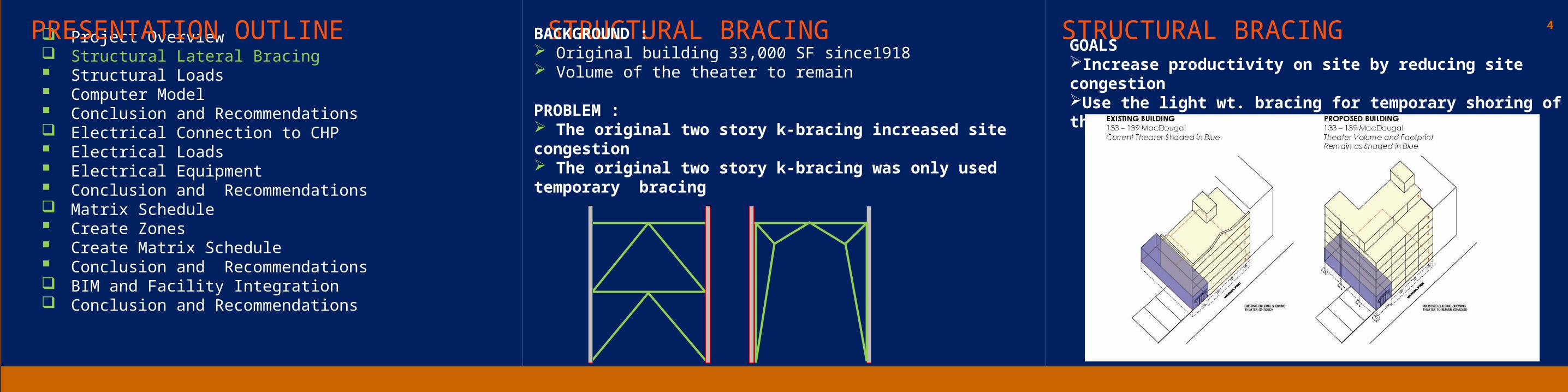
PRESENTATION OUTLINE STRUCTURAL BRACING STRUCTURAL BRACINGBACKGROUND : Original building 33,000 SF since1918 Volume of the theater to remain PROBLEM : The original two story k-bracing increased site congestion The original two story k-bracing was only used temporary bracing
GOALS Increase productivity on site by reducing site congestionUse the light wt. bracing for temporary shoring of the concrete slab
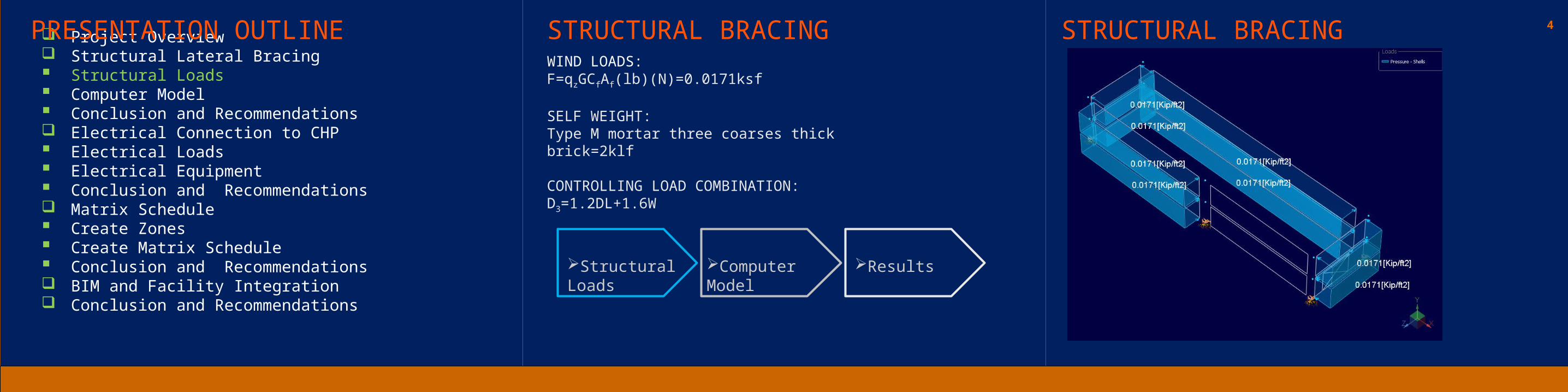
WIND LOADS:F=qzGCfAf(lb)(N)=0.0171ksf
SELF WEIGHT:Type M mortar three coarses thick brick=2klf
CONTROLLING LOAD COMBINATION:D3=1.2DL+1.6W
4 Project Overview Structural Lateral Bracing Structural Loads Computer Model Conclusion and Recommendations Electrical Connection to CHP Electrical Loads Electrical Equipment Conclusion and Recommendations Matrix Schedule Create Zones Create Matrix Schedule Conclusion and Recommendations BIM and Facility Integration Conclusion and Recommendations
PRESENTATION OUTLINE STRUCTURAL BRACING STRUCTURAL BRACING
Structural Loads
Computer Model
Results
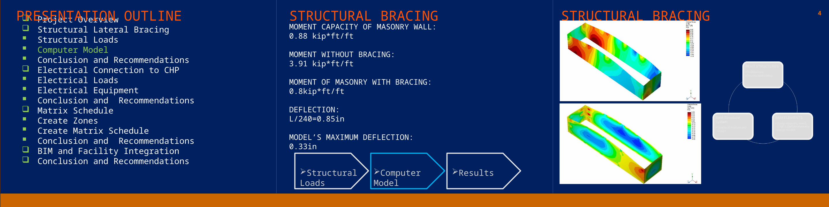
MOMENT CAPACITY OF MASONRY WALL:0.88 kip*ft/ft
MOMENT WITHOUT BRACING:3.91 kip*ft/ft
MOMENT OF MASONRY WITH BRACING:0.8kip*ft/ft
DEFLECTION:L/240=0.85in
MODEL’S MAXIMUM DEFLECTION:0.33in
4 Project Overview Structural Lateral Bracing Structural Loads Computer Model Conclusion and Recommendations Electrical Connection to CHP Electrical Loads Electrical Equipment Conclusion and Recommendations Matrix Schedule Create Zones Create Matrix Schedule Conclusion and Recommendations BIM and Facility Integration Conclusion and Recommendations
PRESENTATION OUTLINE STRUCTURAL BRACING STRUCTURAL BRACING
Structural Loads
Computer Model
Results

MATERIAL TAKEOFF WITH RAM ELEMENTSL 3x3x3/16L 5x5x5/16MC 6x12W6x9
COST$32,000
SCHEDULEOriginal 18.9 daysAlternative 25.1 days
4 Project Overview Structural Lateral Bracing Structural Loads Computer Model Conclusion and Recommendations Electrical Connection to CHP Electrical Loads Electrical Equipment Conclusion and Recommendations Matrix Schedule Create Zones Create Matrix Schedule Conclusion and Recommendations BIM and Facility Integration Conclusion and Recommendations
PRESENTATION OUTLINE STRUCTURAL BRACING STRUCTURAL BRACING
Structural Loads
Computer Model
Results
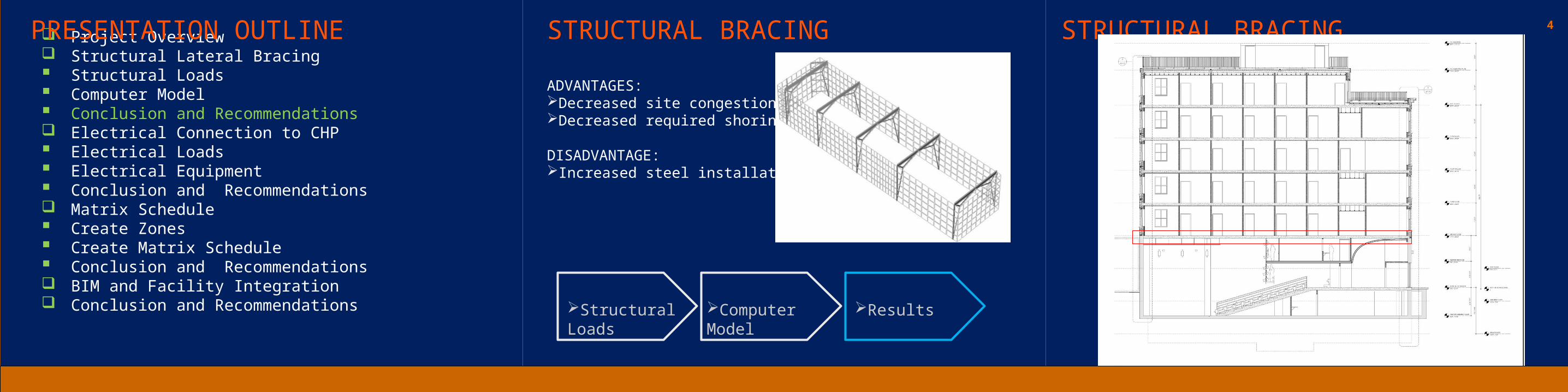
ADVANTAGES:Decreased site congestionDecreased required shoring
DISADVANTAGE:Increased steel installation time
4 Project Overview Structural Lateral Bracing Structural Loads Computer Model Conclusion and Recommendations Electrical Connection to CHP Electrical Loads Electrical Equipment Conclusion and Recommendations Matrix Schedule Create Zones Create Matrix Schedule Conclusion and Recommendations BIM and Facility Integration Conclusion and Recommendations
PRESENTATION OUTLINE STRUCTURAL BRACING STRUCTURAL BRACING
Structural Loads
Computer Model
Results
4 Project Overview Structural Lateral Bracing Structural Loads Computer Model Conclusion and Recommendations Electrical Connection to CHP Electrical Loads Electrical Equipment Conclusion and Recommendations Matrix Schedule Create Zones Create Matrix Schedule Conclusion and Recommendations BIM and Facility Integration Conclusion and Recommendations
PRESENTATION OUTLINE
ELECTRICAL CHP CONNECTION
4 Project Overview Structural Lateral Bracing Structural Loads Computer Model Conclusion and Recommendations Electrical Connection to CHP Electrical Loads Electrical Equipment Conclusion and Recommendations Matrix Schedule Create Zones Create Matrix Schedule Conclusion and Recommendations BIM and Facility Integration Conclusion and Recommendations
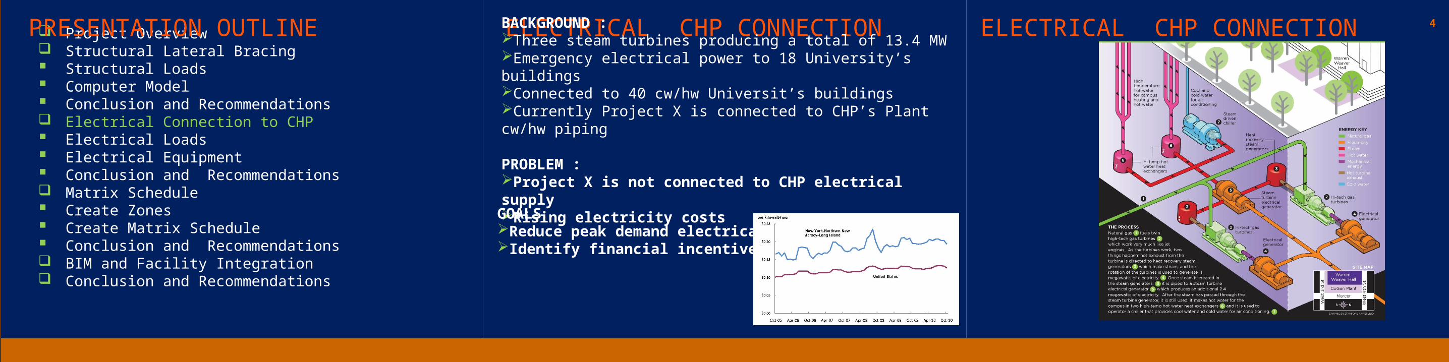
PRESENTATION OUTLINE ELECTRICAL CHP CONNECTION ELECTRICAL CHP CONNECTIONBACKGROUND :Three steam turbines producing a total of 13.4 MWEmergency electrical power to 18 University’s buildingsConnected to 40 cw/hw Universit’s buildingsCurrently Project X is connected to CHP’s Plant cw/hw piping PROBLEM :Project X is not connected to CHP electrical supplyRising electricity costs
GOALS Reduce peak demand electrical loads Identify financial incentives in New York
4 Project Overview Structural Lateral Bracing Structural Loads Computer Model Conclusion and Recommendations Electrical Connection to CHP Electrical Loads Electrical Equipment Conclusion and Recommendations Matrix Schedule Create Zones Create Matrix Schedule Conclusion and Recommendations BIM and Facility Integration Conclusion and Recommendations
PRESENTATION OUTLINE ELECTRICAL CHP CONNECTION ELECTRICAL CHP CONNECTION
Electrical Loads
Equipment Results
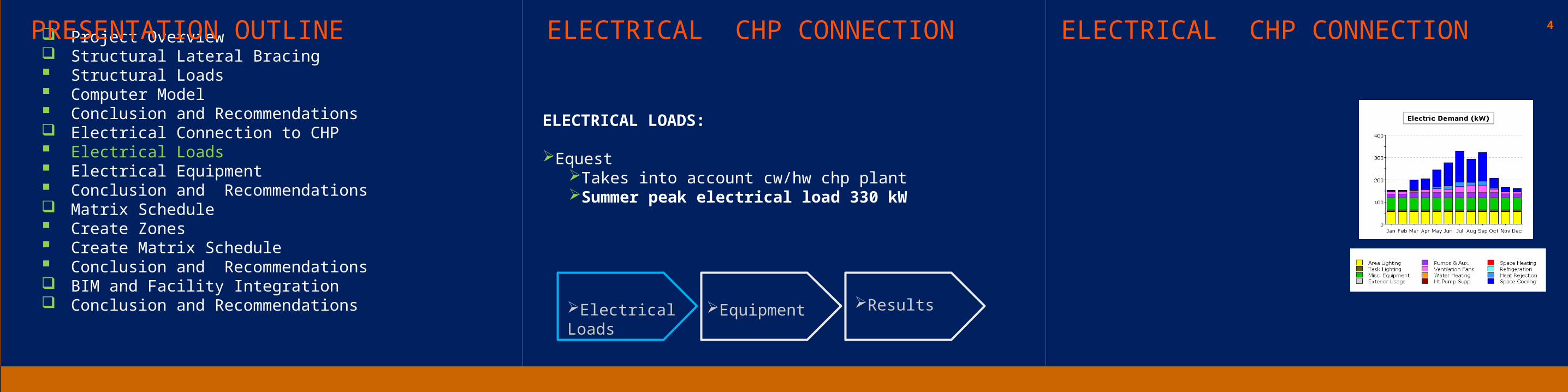
ELECTRICAL LOADS:
EquestTakes into account cw/hw chp plantSummer peak electrical load 330 kW
4 Project Overview Structural Lateral Bracing Structural Loads Computer Model Conclusion and Recommendations Electrical Connection to CHP Electrical Loads Electrical Equipment Conclusion and Recommendations Matrix Schedule Create Zones Create Matrix Schedule Conclusion and Recommendations BIM and Facility Integration Conclusion and Recommendations
PRESENTATION OUTLINE ELECTRICAL CHP CONNECTION ELECTRICAL CHP CONNECTION
Electrical Loads
Equipment Results
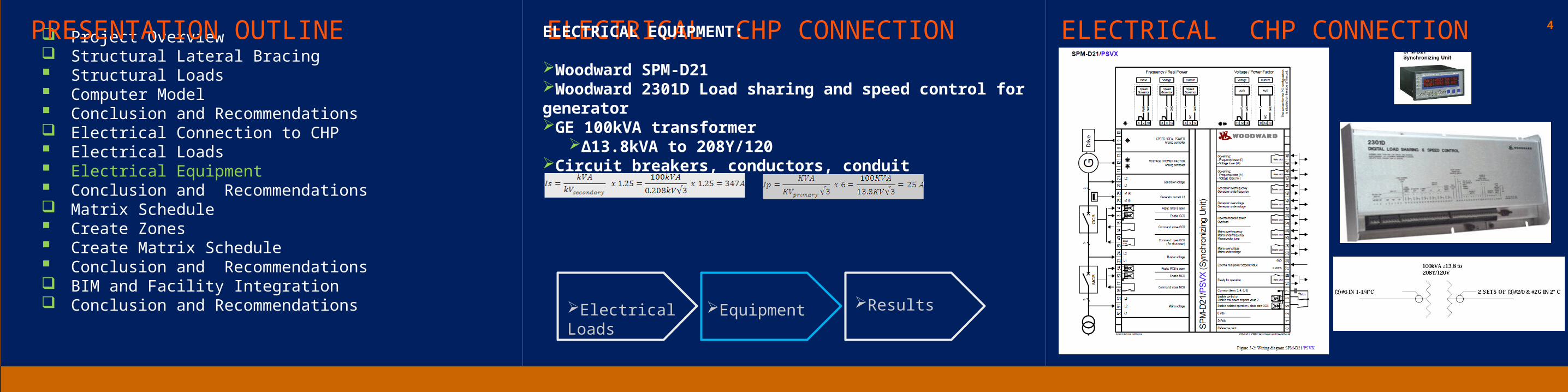
ELECTRICAL EQUIPMENT:
Woodward SPM-D21Woodward 2301D Load sharing and speed control for generator GE 100kVA transformer
∆13.8kVA to 208Y/120Circuit breakers, conductors, conduit
4 Project Overview Structural Lateral Bracing Structural Loads Computer Model Conclusion and Recommendations Electrical Connection to CHP Electrical Loads Electrical Equipment Conclusion Matrix Schedule Create Zones Create Matrix Schedule Conclusion and Recommendations BIM and Facility Integration Conclusion and Recommendations
PRESENTATION OUTLINE ELECTRICAL CHP CONNECTION ELECTRICAL CHP CONNECTION
Electrical Loads
Equipment Results
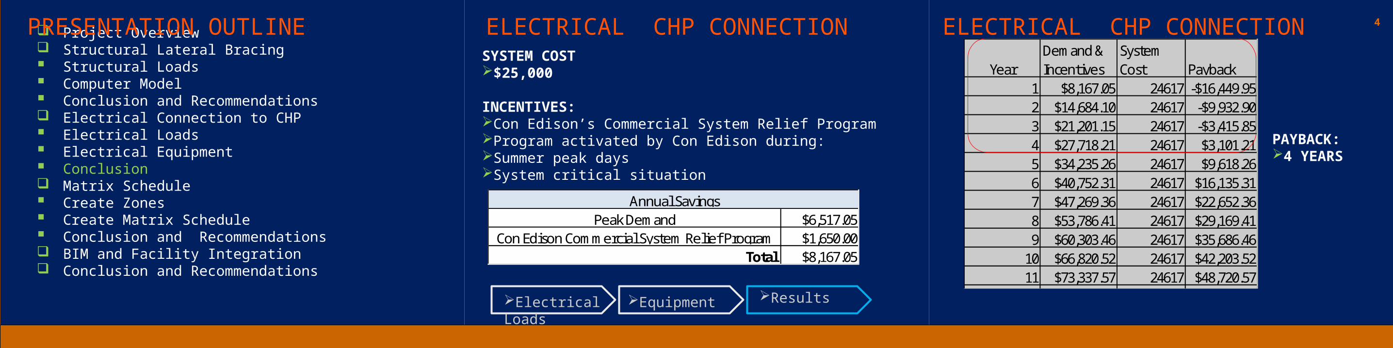
SYSTEM COST$25,000
INCENTIVES:Con Edison’s Commercial System Relief ProgramProgram activated by Con Edison during: Summer peak days System critical situation
YearDemand & Incentives
System Cost Payback
1 $8,167.05 24617 -$16,449.952 $14,684.10 24617 -$9,932.903 $21,201.15 24617 -$3,415.854 $27,718.21 24617 $3,101.215 $34,235.26 24617 $9,618.266 $40,752.31 24617 $16,135.317 $47,269.36 24617 $22,652.368 $53,786.41 24617 $29,169.419 $60,303.46 24617 $35,686.46
10 $66,820.52 24617 $42,203.5211 $73,337.57 24617 $48,720.5712 $79,854.62 24617 $55,237.6213 $86,371.67 24617 $61,754.6714 $92,888.72 24617 $68,271.7215 $99,405.77 24617 $74,788.77
$6,517.05$1,650.00$8,167.05Total
Annual SavingsPeak Demand
Con Edison Commercial System Relief Program
PAYBACK:4 YEARS
4 Project Overview Structural Lateral Bracing Structural Loads Computer Model Conclusion and Recommendations Electrical Connection to CHP Electrical Loads Electrical Equipment Conclusion and Recommendations Matrix Schedule Create Zones Create Matrix Schedule Conclusion and Recommendations BIM and Facility Integration Conclusion and Recommendations
PRESENTATION OUTLINE
MATRIX SCHEDULE
4 Project Overview Structural Lateral Bracing Structural Loads Computer Model Conclusion and Recommendations Electrical Connection to CHP Electrical Loads Electrical Equipment Conclusion and Recommendations Matrix Schedule Create Zones Create Matrix Schedule Conclusion and Recommendations BIM and Facility Integration Conclusion and Recommendations
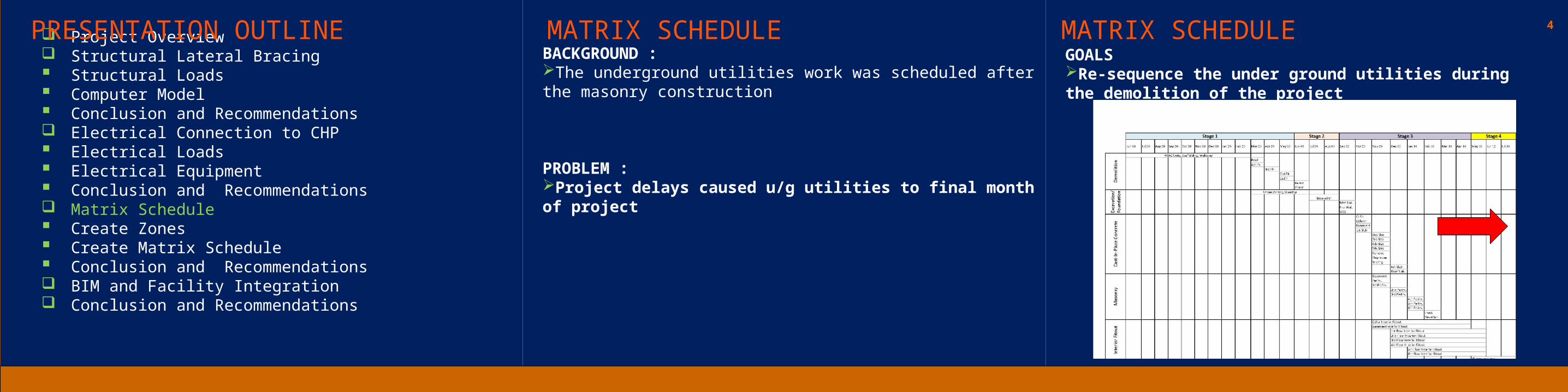
PRESENTATION OUTLINE MATRIX SCHEDULE MATRIX SCHEDULEBACKGROUND :The underground utilities work was scheduled after the masonry construction
PROBLEM :Project delays caused u/g utilities to final month of project
GOALS Re-sequence the under ground utilities during the demolition of the project

4 Project Overview Structural Lateral Bracing Structural Loads Computer Model Conclusion and Recommendations Electrical Connection to CHP Electrical Loads Electrical Equipment Conclusion and Recommendations Matrix Schedule Create Zones Create Matrix Schedule Conclusion and Recommendations BIM and Facility Integration Conclusion and Recommendations
PRESENTATION OUTLINE MATRIX SCHEDULE

4 Project Overview Structural Lateral Bracing Structural Loads Computer Model Conclusion and Recommendations Electrical Connection to CHP Electrical Loads Electrical Equipment Conclusion and Recommendations Matrix Schedule Create Zones Create Matrix Schedule Conclusion and Recommendations BIM and Facility Integration Conclusion and Recommendations
PRESENTATION OUTLINE MATRIX SCHEDULE MATRIX SCHEDULE
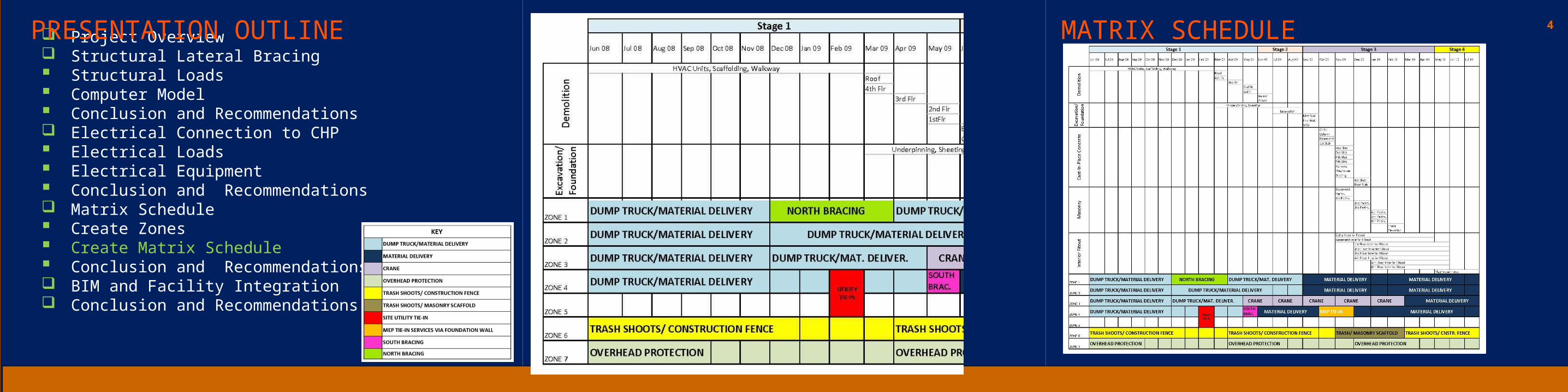
PROJECT PHASES:
Stage 1: UNDER GROUND CHP/UTILITY, DEMOLITION
Stage 2: EXCAVATION, FOUNDATIONS
Stage 3: CAST-IN-PLACE BUILDING FRAME, FAÇADE, INTERIOR FIT-OUT
Stage 4: THEATER INTERIOR FIT-OUT, LANDSCAPING
4 Project Overview Structural Lateral Bracing Structural Loads Computer Model Conclusion and Recommendations Electrical Connection to CHP Electrical Loads Electrical Equipment Conclusion and Recommendations Matrix Schedule Create Zones Create Matrix Schedule Conclusion and Recommendations BIM and Facility Integration Conclusion and Recommendations
PRESENTATION OUTLINE MATRIX SCHEDULE MATRIX SCHEDULE
CONCLUSIONS:FOR LOGISTICAL REASONS IT IS ALWAYS BETTER TO DO THE SITE U/G UTILITY BEFORE THE SUPER STRUCTURE CONSTRUCTION BEGINSTHE CROWDED CONSTRUCTION SITE IN NYC PROVED TO BE THE IDEAL SELECTION FOR CREATING A MATRIX SCHEDULE
4 Project Overview Structural Lateral Bracing Structural Loads Computer Model Conclusion and Recommendations Electrical Connection to CHP Electrical Loads Electrical Equipment Conclusion and Recommendations Matrix Schedule Utilities Schedule Facade Schedule Super Structure Schedule Integrated Schedule Conclusion and Recommendations BIM and Facility Integration Conclusion and Recommendations
PRESENTATION OUTLINE
BIM AND FM INTEGRATION

4 Project Overview Structural Lateral Bracing Structural Loads Computer Model Conclusion and Recommendations Electrical Connection to CHP Electrical Loads Electrical Equipment Conclusion and Recommendations Matrix Schedule Utilities Schedule Facade Schedule Super Structure Schedule Integrated Schedule Conclusion and Recommendations BIM and Facility Integration Conclusion and Recommendations
PRESENTATION OUTLINE BIM AND FM INTEGRATION BIM AND FM INTEGRATIONBACKGROUND :
50% of the building construction industry is now using BIM
PROBLEM :Building owners don’t know how to use BIM after constructionBuilding owners don’t require the FM data to be included in the BIMInputting FM data into CMMS (Computer Maintenance Management System) can take up to six months
GOALS

4 Project Overview Structural Lateral Bracing Structural Loads Computer Model Conclusion and Recommendations Electrical Connection to CHP Electrical Loads Electrical Equipment Conclusion and Recommendations Matrix Schedule Create Zones Create Matrix Schedule Conclusion and Recommendations BIM and Facility Integration Conclusion and Recommendations
PRESENTATION OUTLINE BIM AND FM INTEGRATIONJob Shadowing
Field Data
ParametersUniformatCoBie
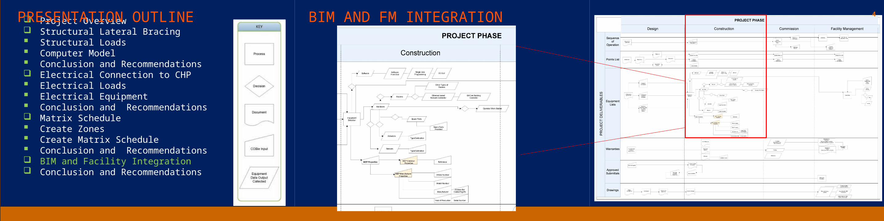
Process Map
Available TechnologyMost technicians don’t have laptopsMost only have a PDA
Limited screen size and Limited File SizeComputer work stations are available throughout campus
Facility Management Work Orders Description of Work: Room too cold. HVAC Unit Blowing Cold Air Location: 0503000-543 DEIKE Building -05 Staff Office Equipment: F/P: Facility planningRPT: 3:45pm 12/15/2010 Contact: Name Phone Number:
Location: Hyperlink to drawingEquipment: link to equipment’s Excel file

4 Project Overview Structural Lateral Bracing Structural Loads Computer Model Conclusion and Recommendations Electrical Connection to CHP Electrical Loads Electrical Equipment Conclusion and Recommendations Matrix Schedule Create Zones Create Matrix Schedule Conclusion and Recommendations BIM and Facility Integration Conclusion and Recommendations
PRESENTATION OUTLINE BIM AND FM INTEGRATIONJob Shadowing
Field Data
ParametersUniformatCoBie
Process Map
Equipment NumberOperate Range Temp -20ºF to 140ºF (-29ºC to 60ºC)Operate Range Humidity 10 to 90% relative humidity,
Multi-Equipment Contoller & Router Type Controller & RouterController, receiver Model # ME-LGR LineElectric, Single Snap switch Manufacturer ALC
Communication BACnet Building Controller (B-BC)Communication EIA-232-485 port 156kbpsMicroprocessor 32-bitMemory 16 MbyteProtection Built-in surge and transient protectionVoltage 24 V-ac ± 10%Frequency 50 to 60HzPower 10 WattsServices MS-TP Channel for ctrl integration
D3068 Building Automation SystemsD3060 Controls & InstrumentationD30 HVAC
Asset Information organized according to PSU UNIFORMAT Standard

4 Project Overview Structural Lateral Bracing Structural Loads Computer Model Conclusion and Recommendations Electrical Connection to CHP Electrical Loads Electrical Equipment Conclusion and Recommendations Matrix Schedule Create Zones Create Matrix Schedule Conclusion and Recommendations BIM and Facility Integration Conclusion and Recommendations
PRESENTATION OUTLINE BIM AND FM INTEGRATIONJob Shadowing
Field Data
ParametersUniformatCOBie
Process Map
Name Contoller & RouterCreatedBy [email protected] 7/31/2011Category ATCDescriptionAssetTypeManufacturer ALCModelNumber ME-LGR LinePartsWarrantyGuarantorPartsWarrantyEndDateLaborWarrantyGuarantorLaborWarrantyStartDateLaborWarrantyEndDateExtSystemExtObjectExtIdentifierReplacementCostExpectedLifeDurationUnitWarrantyDescription
Type Worksheet
Multi-Equipment Contoller & Router Controller,
receiver Electric, Single Snap switch
NameCreatedByCreatedOnCategoryDescriptionTypeNameSuppliersExtSystemExtObjectExtIdentifierSetNumberPartNumber
Spare Worksheet
Multi-Equipment Contoller & Router Controller, receiver Electric, Single Snap
switch
Name Contoller/RouterCreatedBy [email protected] 7/31/2011Category ATCDescriptionExtSystemExtObjectExtIdentifier
Resource Worksheet
Multi-Equipment Contoller & Router Controller, receiver Electric, Single Snap
switch
NameCreatedByCreatedOnTypeNameSpace NamesDescriptionExtSystemExtObjectExtIdentifierSerialNumberInstallationDateTagNumberBarCodeAssetIdentifier
Component Worksheet
Multi-Equipment Contoller & Router Controller, receiver Electric, Single Snap
switch
Type worksheet:Overview of the designers, builders, and manufactures’ information.
4 Project Overview Structural Lateral Bracing Structural Loads Computer Model Conclusion and Recommendations Electrical Connection to CHP Electrical Loads Electrical Equipment Conclusion and Recommendations Matrix Schedule Create Zones Create Matrix Schedule Conclusion and Recommendations BIM and Facility Integration Conclusion and Recommendations
PRESENTATION OUTLINE BIM AND FM INTEGRATION
4 Project Overview Structural Lateral Bracing Structural Loads Computer Model Conclusion and Recommendations Electrical Connection to CHP Electrical Loads Electrical Equipment Conclusion and Recommendations Matrix Schedule Create Zones Create Matrix Schedule Conclusion and Recommendations BIM and Facility Integration Conclusion and Recommendations
PRESENTATION OUTLINE BIM AND FM INTEGRATION BIM AND FM INTEGRATION
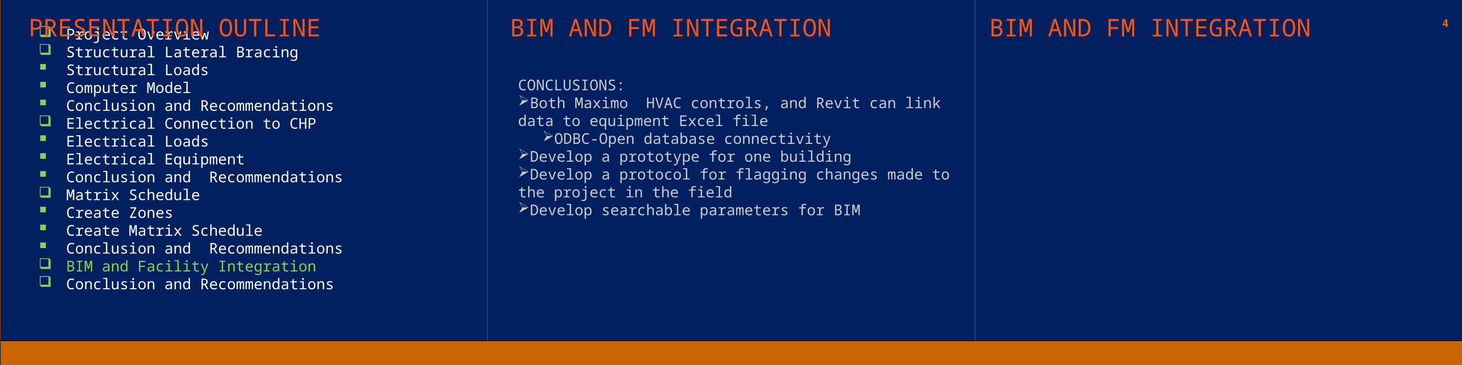
CONCLUSIONS:Both Maximo HVAC controls, and Revit can link data to equipment Excel file
ODBC-Open database connectivityDevelop a prototype for one buildingDevelop a protocol for flagging changes made to the project in the fieldDevelop searchable parameters for BIM

FRIENDS AND FAMILY ARCHITECTURAL ENGINEERING FACULTYSKANSKA BUILDING USAOFFICE OF PHYSICAL PLANT (OPP)
4 Project Overview Structural Lateral Bracing Structural Loads Computer Model Conclusion and Recommendations Electrical Connection to CHP Electrical Loads Electrical Equipment Conclusion and Recommendations Matrix Schedule Create Zones Create Matrix Schedule Conclusion and Recommendations BIM and Facility Integration Conclusion and Recommendations
PRESENTATION OUTLINE ACKNOWLEDGEMENTS QUESTIONSSUMMARY & CONCLUSIONS
STRUCTURAL BRACING Reduce site congestionDecreased required shoringIncreased installation time
ELECTRICAL CHP CONNECTIONSystem cost $25,000 with 4 year payback
MATRIX SCHEDULEFor logistical reasons it is always better to do the u/g utilities before structureThe crowded construction site of NYC proved to be the ideal selection for creating a matrix schedule.
BIM AND FM INTEGRATION:Both Maximo HVAC controls and Revit can link data to equipment Excel fileDevelop a prototype for one buildingDevelop a protocol for flagging changesDevelop searchable parameters for BIM and FM