m21 knig2461 04 ism c21 - media.physicsisbeautiful.com
TRANSCRIPT
© Copyright 2017 Pearson Education, Inc. All rights reserved. This material is protected under all copyright laws as they currently exist. No portion of this material may be reproduced, in any form or by any means, without permission in writing from the publisher.
21-1
Conceptual Questions
21.1. sW W= − . (a) s0, 0W W< > . Work is done by the system; the area under the curve is positive. (b) s0, 0W W> < . Work is done on the system to compress it to a smaller volume. (c) s0, 0W W> < . More work is done on the system than by the system.
21.2. 3 1 2 4W W W W> = > . The amount of work done by the gas is the area inside the closed cycle loop (traversed in a clockwise direction).
21.3. No. out
H
what you getwhat you had to pay
WQ
η = = . You cannot get out more than you put in.
21.4. (a) 1 (b) 3 (c) 3 (d) 2 In stage 1 the volume is fixed (so no work is done) but the temperature increases, so heat was added. In stage 2 on the isotherm work is done by the gas. In stage 3 work is done on the gas and heat is removed.
21.5. 3 1 2 4η η η η> = > . out
H
WQ
η = 14
10η = 2
40100
η = 36
10η = 4
6100
η =
21.6. The thermal efficiency is larger for engine 1; the same amount of heat is added per cycle in both engines, but
the cycle for engine 1 has a larger outW due to the larger enclosed area: out
H
WQ
η = .
21.7. It is an isothermal process with equal amounts of heat added to the system and work done by the system.
21.8. (a) No; cannot have out in15 J 10 J .>
(b) Yes, this is a heat engine with out
H
4 0 4,10
WQ
η = = = . which is less than Carnot 0 5.η = .
(c) No, it isn’t possible to have Carnot:η η> out
H
6 0 6,10
WQ
η = = = . but Carnot 0 5.η = .
HEAT ENGINES AND REFRIGERATORS
21

21-2 Chapter 21
© Copyright 2017 Pearson Education, Inc. All rights reserved. This material is protected under all copyright laws as they currently exist. No portion of this material may be reproduced, in any form or by any means, without permission in writing from the publisher.
21.9. (a) No, the purpose of a refrigerator is to remove heat from the cold reservoir, and this diagram dumps heat into the cold reservoir. (b) Yes, which is less than Carnot 1.K =
(c) No, C
in
20 2,10
QKW
= = = which is less than Carnot 1.K =
21.10. No. The first law of thermodynamics (energy conservation) for a refrigerator or air conditioner requires H C .Q Q W= + There are no perfect refrigerators (second law), so 0W > (work must be done by the compressor) and
thus H C.Q Q> Because the “air conditioner” exhausts more heat into the room than it extracts from the room, the net effect is to increase the room temperature, not decrease it.
21.11. Yes, the first law says that energy is conserved, so we will never get more work out of the heat engine than heat energy is transferred to the system. In fact, the second law (informal statement #4) says that there are no perfect heat engines with 1,η = so there is always some waste heat exhausted to the cold reservoir.
Exercises and Problems
Exercises Section 21.1 Turning Heat into Work Section 21.2 Heat Engines and Refrigerators 21.1. Solve: During each cycle, the work done by the engine is out 200 JW = and the engine exhausts C 400 JQ = of heat energy. By conservation of energy,
H out C 200 J 400 J 600 JQ W Q= + = + = Thus, the efficiency of the engine is
out
H
400 J 0 33600 J
WQ
η = = = .
21.2. Solve: (a) The engine has a thermal efficiency of 40% 0 40η = = . and a work output of 100 J per cycle. The heat input is calculated as follows:
outH
H H
100 J0 40 250 JW QQ Q
η = ⇒ . = ⇒ =
(b) Because out H C,W Q Q= − the heat exhausted is
C H out 250 J 100 J 150 JQ Q W= − = − =
21.3. Solve: (a) During each cycle, the heat transferred into the engine is H 55 kJ,Q = and the heat exhausted is
C 40 kJ.Q = The thermal efficiency of the heat engine is
C
H
40 kJ1 1 0 27 27%55 kJ
η = − = − = . =
(b) The work done by the engine per cycle is out H C 55 kJ 40 kJ 15 kJW Q Q= − = − =
21.4. Solve: (a) The heat extracted from the cold reservoir is calculated as follows:
C CC
in4 0 200 J
50 JQ QK QW
= ⇒ . = ⇒ =
(b) The heat exhausted to the hot reservoir is
H C in 200 J 50 J 250 JQ Q W= + = + =

Heat Engines and Refrigerators 21-3
© Copyright 2017 Pearson Education, Inc. All rights reserved. This material is protected under all copyright laws as they currently exist. No portion of this material may be reproduced, in any form or by any means, without permission in writing from the publisher.
21.5. Solve: The coefficient of performance of the refrigerator is C H in
in in
600 J 200 J 2 0200 J
Q Q WKW W
− −= = = = .
21.6. Solve: The amount of heat discharged per second is calculated as follows:
9out outC out
H C out
1 11 (900 MW) 1 1 913 10 W0 32
W W Q WQ Q W
ηη
⎛ ⎞ ⎛ ⎞= = ⇒ = − = − = . ×⎜ ⎟ ⎜ ⎟+ .⎝ ⎠⎝ ⎠
That is, each second the electric power plant discharges 91 913 10 J. × of energy into the ocean. Since a typical American house needs 42 0 10 J. × of energy per second for heating, the number of houses that could be heated with the waste heat is 9 4(1 913 10 J)/(2 0 10 J) 96,000.. × . × =
21.7. Model: Assume that the car engine follows a closed cycle. Solve: (a) Since 2400 rpm is 40 cycles per second, the work output of the car engine per cycle is
outkJ 1 s kJ kJ500 12 5 13s 40 cycles cycle cycle
W⎛ ⎞⎛ ⎞= = . ≈⎜ ⎟⎜ ⎟
⎝ ⎠⎝ ⎠
(b) The heat input per cycle is calculated as follows:
outH
H
12 5 kJ 62 5 kJ0 20
W QQ
η .= ⇒ = = .
.
The heat exhausted per cycle is
C H in 62 5 kJ 12 5 kJ 50 kJQ Q W= − = . − . =
21.8. Solve: The amount of heat removed from the water in cooling it down in 1 hour is C water waterQ m c T= Δ . The mass of the water is
3 3 3 3water water water
4C
(1000 kg/m )(1 L) (100 kg/m )(10 m ) 1 0 kg
(1 0 kg)(4190 J/kg K)(20 C 5 C) 6 285 10 J
m V
Q
ρ −= = = = .
= . ° − ° = . ×
The rate of heat removal from the refrigerator is 4
C6 285 10 J 17 46 J/s
3600 sQ . ×
= = .
The refrigerator does work 8.0W = W 8.0 J/s= to remove this heat. Thus the performance coefficient of the refrigerator is
17 46 J/s 2 28 0 J/s
K .= = .
.
Section 21.3 Ideal-Gas Heat Engines Section 21.4 Ideal-Gas Refrigerators 21.9. Model: Process A is adiabatic, process B is isochoric, and process C is isothermal. Solve: Process A is adiabatic, so 0 J.Q = Work sW is positive as the gas expands. Since s th th0 J, Q W E E= + Δ = Δ must be negative. The temperature falls during an adiabatic expansion. Process B is isochoric. No work is done
s( 0 J),W = and Q is positive as heat energy is added to raise the temperature th( positive).EΔ Process C is isothermal so 0TΔ = and th 0 J.EΔ = The gas is compressed, so sW is negative. sQ W= for an isothermal process, so Q is negative. Heat energy is withdrawn during the compression to keep the temperature constant.

21-4 Chapter 21
© Copyright 2017 Pearson Education, Inc. All rights reserved. This material is protected under all copyright laws as they currently exist. No portion of this material may be reproduced, in any form or by any means, without permission in writing from the publisher.
thEΔ sW Q A − + 0 B + 0 + C 0 − −
21.10. Model: Process A is isochoric, process B is adiabatic, process C is isothermal, and process D is isobaric. Solve: Process A is isochoric, so the increase in pressure increases the temperature and hence the thermal energy. Because th s s and 0 J,E Q W WΔ = − = Q increases for process A. Process B is adiabatic, so Q = 0 J. Ws is positive because of the increase in volume. Since s th th0 J , Q W E E= = + Δ Δ is negative for process B. Process C is isothermal, so T is constant and hence th 0 J.EΔ = The work done sW is positive because the gas expands. Because
s th ,Q W E= + Δ Q is positive for process B. Process D is isobaric, so the decrease in volume leads to a decrease in temperature and hence a decrease in the thermal energy. Due to the decrease in volume, sW is negative. Because
s th ,Q W E= + Δ Q also decreases for process D.
thEΔ sW Q A + 0 + B − + 0 C 0 + + D − − −
21.11. Model: The work done by the gas per cycle is the area inside the closed p-versus-V curve. Solve: The area inside the triangle is
6 3 6 31out 2
56 31
2
(3 atm 1 atm)(600 10 m 200 10 m )
1 013 10 Pa2 atm (400 10 m ) 40 J1 atm
W − −
−
= − × − ×
⎛ ⎞. ×= × × =⎜ ⎟⎜ ⎟
⎝ ⎠
21.12. Solve: The work done by the gas per cycle is the area enclosed within the pV curve. We have
3 3 51max max2 6 3
5max
2(60 J)60 J ( 100 kPa)(800 cm 200 cm ) 1 0 10 Pa600 10 m
3 0 10 Pa 300 kPa
p p
p
−= − − ⇒ = − . ××
= . × =
21.13. Model: The heat engine follows a closed cycle, which consists of four individual processes. Solve: (a) The work done by the heat engine per cycle is the area enclosed by the p-versus-V graph. We get
6 3out (400 kPa 100 kPa)(100 10 m ) 30 JW −= − × =
The heat energy leaving the engine is C 90 J 25 J 115 J.Q = + = The heat input is calculated as follows:
out H C H C out 115 J 30 J 145 J 0.15 kJW Q Q Q Q W= − ⇒ = + = + = ≈
(b) The thermal efficiency of the engine is
out
H
30 J 0 21145 J
WQ
η = = = .

Heat Engines and Refrigerators 21-5
© Copyright 2017 Pearson Education, Inc. All rights reserved. This material is protected under all copyright laws as they currently exist. No portion of this material may be reproduced, in any form or by any means, without permission in writing from the publisher.
21.14. Model: The heat engine follows a closed cycle, starting and ending in the original state. The cycle consists of three individual processes. Solve: (a) The work done by the heat engine per cycle is the area enclosed by the p-versus-V graph. We get
6 31out 2 (200 kPa)(100 10 m ) 10 JW −= × =
The heat energy leaving the engine is C 114 J.Q = Because out H C,W Q Q= − the heat energy exhausted is
H out C 10 J 114 J 124 JQ W Q= + = + =
(b) The thermal efficiency of the engine is
out
H
10 J 0 081124 J
WQ
η = = = .
Assess: Practical engines have thermal efficiencies in the range 0 1 0 4η ≈ . − . and this one isn’t quite there.
21.15. Model: The heat engine follows a closed cycle. Solve: (a) The work done by the gas per cycle is the area inside the closed p-versus-V curve. We get
3 3 3 6 31 1out 2 2(300 kPa 100 kPa)(600 cm 200 cm ) (200 10 Pa)(400 10 m ) 40 JW −= − − = × × =
The heat exhausted is C 180 J 100 J 280 J.Q = + = The thermal efficiency of the engine is
out out
H C out
40 J 0 13280 J 40 J
W WQ Q W
η = = = = .+ +
(b) The heat extracted from the hot reservoir is H C out 320 J.Q Q W= + =
21.16. Model: The heat engine follows a closed cycle. Solve: The work done by the gas per cycle is the area inside the closed p-versus-V curve. We get
3 3 3 6 31 1out 2 2(300 kPa 100 kPa)(600 cm 300 cm ) (200 10 Pa)(300 10 m ) 30 JW −= − − = × × =
Because out H C,W Q Q= − the heat exhausted is
C H out (225 J 90 J) 30 J 315 J 30 J 285 JQ Q W= − = + − = − =
21.17. Model: The Brayton cycle involves two adiabatic processes and two isobaric processes. The adiabatic processes involve compression and expansion through the turbine. Solve: The thermal efficiency for the Brayton cycle is (1 )/
B p1 ,r γ γη −= − where P V/C Cγ = and pr is the pressure ratio. For a diatomic gas 1.4.γ = For an adiabatic process,
1 2 2 1 1 21 2 / ( / )p V p V p p V Vγ γ γ= ⇒ =
Because the volume is halved, 12 12V V= so
1 4p 2 1/ (2) 2 2 639r p p γ .= = = = .
The efficiency is 0.4/1.4
B 1 (2.639) 0.24η −= − =
21-6 Chapter 21
© Copyright 2017 Pearson Education, Inc. All rights reserved. This material is protected under all copyright laws as they currently exist. No portion of this material may be reproduced, in any form or by any means, without permission in writing from the publisher.
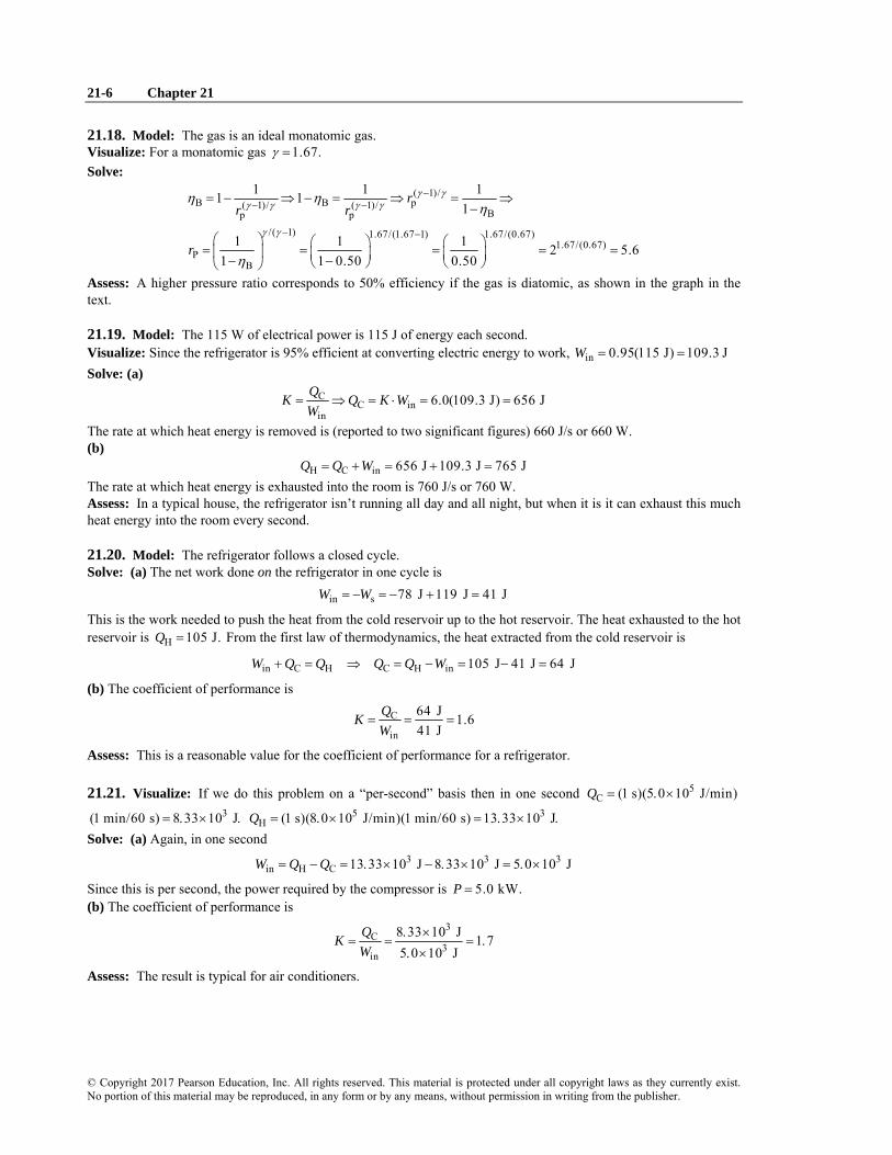
21.18. Model: The gas is an ideal monatomic gas. Visualize: For a monatomic gas 1.67.γ = Solve:
( 1)/B B p( 1)/ ( 1)/
Bp p
/( 1) 1.67/(1.67 1) 1.67/(0.67)1.67/(0.67)
PB
1 1 11 11
1 1 1 2 5.61 1 0.50 0.50
rr r
r
γ γγ γ γ γ
γ γ
η ηη
η
−− −
− −
= − ⇒ − = ⇒ = ⇒−
⎛ ⎞ ⎛ ⎞ ⎛ ⎞= = = = =⎜ ⎟ ⎜ ⎟ ⎜ ⎟− −⎝ ⎠ ⎝ ⎠⎝ ⎠
Assess: A higher pressure ratio corresponds to 50% efficiency if the gas is diatomic, as shown in the graph in the text.
21.19. Model: The 115 W of electrical power is 115 J of energy each second. Visualize: Since the refrigerator is 95% efficient at converting electric energy to work, in 0.95(115 J) 109.3 JW = = Solve: (a)
CC in
in6.0(109.3 J) 656 JQK Q K W
W= ⇒ = ⋅ = =
The rate at which heat energy is removed is (reported to two significant figures) 660 J/s or 660 W. (b)
H C in 656 J 109.3 J 765 JQ Q W= + = + = The rate at which heat energy is exhausted into the room is 760 J/s or 760 W. Assess: In a typical house, the refrigerator isn’t running all day and all night, but when it is it can exhaust this much heat energy into the room every second.
21.20. Model: The refrigerator follows a closed cycle. Solve: (a) The net work done on the refrigerator in one cycle is
in s 78 J 119 J 41 JW W= − = − + =
This is the work needed to push the heat from the cold reservoir up to the hot reservoir. The heat exhausted to the hot reservoir is H 105 J.Q = From the first law of thermodynamics, the heat extracted from the cold reservoir is
in C H C H in 105 J 41 J 64 JW Q Q Q Q W+ = ⇒ = − = − =
(b) The coefficient of performance is
C
in
64 J 1.641 J
QKW
= = =
Assess: This is a reasonable value for the coefficient of performance for a refrigerator.
21.21. Visualize: If we do this problem on a “per-second” basis then in one second 5C (1 s)(5 0 10 J/min)Q = . ×
3(1 min/60 s) 8 33 10 J= . × . 5 3H (1 s)(8 0 10 J/min)(1 min/60 s) 13 33 10 JQ = . × = . × .
Solve: (a) Again, in one second 3 3 3
in H C 13 33 10 J 8 33 10 J 5 0 10 JW Q Q= − = . × − . × = . ×
Since this is per second, the power required by the compressor is 5.0 kW.P = (b) The coefficient of performance is
3C
3in
8 33 10 J 1 75 0 10 J
QKW
. ×= = = .
. ×
Assess: The result is typical for air conditioners.

Heat Engines and Refrigerators 21-7
© Copyright 2017 Pearson Education, Inc. All rights reserved. This material is protected under all copyright laws as they currently exist. No portion of this material may be reproduced, in any form or by any means, without permission in writing from the publisher.
Section 21.5 The Limits of Efficiency Section 21.6 The Carnot Cycle 21.22. Model: The efficiency of a Carnot engine Carnot( )η depends only on the temperatures of the hot and cold reservoirs. On the other hand, the thermal efficiency ( )η of a heat engine depends on the heats HQ and C.Q Solve: (a) According to the first law of thermodynamics, H out C.Q W Q= + For engine (a), H 500 J,Q = C 200 JQ = and out 300 J,W = so the first law of thermodynamics is obeyed. For engine (b), H C500 J, 200 JQ Q= = and
out 200 J,W = so the first law is violated. For engine (c) H C300 J, 200 JQ Q= = and out 100 J,W = so the first law of thermodynamics is obeyed. (b) For the three heat engines, the maximum or Carnot efficiency is
CCarnot
H
300 K1 1 0 50600 K
TT
η = − = − = .
Engine (a) has
C out
H H
300 J1 0 60500 J
Q WQ Q
η = − = = = .
This is larger than Carnot ,η thus violating the second law of thermodynamics. For engine (b),
outCarnot
H
200 J 0 40500 J
WQ
η η= = = . <
so the second law is obeyed. Engine (c) has a thermal efficiency of
Carnot100 J 0 33300 J
η η= = . <
so the second law of thermodynamics is obeyed.
21.23. Model: For a refrigerator H C in ,Q Q W= + and the coefficient of performance and the Carnot coefficient of performance are
C CCarnot
in H C,Q TK K
W T T= =
−
Solve: (a) For refrigerator (a) H C in (60 J 40 J 20 J),Q Q W= + = + so the first law of thermodynamics is obeyed. For refrigerator (b) 50 J 40 J 10 J,= + so the first law of thermodynamics is obeyed. For the refrigerator (c) 40 J 30 J 20 J,≠ + so the first law of thermodynamics is violated. (b) For the three refrigerators, the maximum coefficient of performance is
CCarnot
H C
300 K 3400 K 300 K
TKT T
= = =− −
For refrigerator (a),
CCarnot
in
40 J 220 J
QK KW
= = = <
so the second law of thermodynamics is obeyed. For refrigerator (b),
CCarnot
in
40 J 410 J
QK KW
= = = >
so the second law of thermodynamics is violated. For refrigerator (c),
Carnot30 J 1 520 J
K K= = . <
so the second law is obeyed.

21-8 Chapter 21
© Copyright 2017 Pearson Education, Inc. All rights reserved. This material is protected under all copyright laws as they currently exist. No portion of this material may be reproduced, in any form or by any means, without permission in writing from the publisher.
21.24. Model: The efficiency of a Carnot engine depends only on the absolute temperatures of the hot and cold reservoirs. Solve: The efficiency of a Carnot engine is
C CCarnot C
H1 0 60 1 280 K 7 C
(427 273) KT T TT
η = − ⇒ . = − ⇒ = = °+
Assess: A “real” engine would need a lower temperature than 7 C° to provide 60% efficiency because no real engine can match the Carnot efficiency.
21.25. Model: The efficiency of an ideal engine (or Carnot engine) depends only on the temperatures of the hot and cold reservoirs. Solve: (a) The engine’s thermal efficiency is
out out
H C out
10 J 0 40 40%15 J 10 J
W WQ Q W
η = = = = . =+ +
(b) The efficiency of a Carnot engine is Carnot C H1 / .T Tη = − The minimum temperature in the hot reservoir is found as follows:
HH
293 K0 40 1 488 K 215 CTT
. = − ⇒ = = °
This is the minimum possible temperature. In a real engine, the hot-reservoir temperature would be higher than 215°C because no real engine can match the Carnot efficiency.
21.26. Model: Assume that the heat engine follows a closed cycle. Solve: (a) The engine’s thermal efficiency is
out out
H C out
200 J 0 25 25%600 J 200 J
W WQ Q W
η = = = = . =+ +
(b) The thermal efficiency of a Carnot engine is Carnot C H1 / .T Tη = − For this to be 25%,
CC0 25 1 504 8 K 232 C
(400 273) KT T. = − ⇒ = . = °+
21.27. Solve: (a) The efficiency of the Carnot engine is
CCarnot
H
300 K1 1 0 40 40%500 K
TT
η = − = − = . =
(b) An engine with power output of 1000 W does out 1000 JW = of work during each 1 s.tΔ = A Carnot engine has a heat input that is
outin
Carnot
1000 J 2500 J0 40
WQη
= = =.
during each 1 s.tΔ = The rate of heat input is 2500 J/s 2500 W.= (c) out in out| |,W Q Q= − so the heat output during 1 stΔ = is out in out| | 1500 J.Q Q W= − = The rate of heat output is thus 1500 J/s 1500 W.=
21.28. Model: We will use Equation 21.27 for the efficiency of a Carnot engine.
CCarnot
H1 T
Tη = −
We are given H 673 KT = and the original efficiency Carnot 0 40.η = .

Heat Engines and Refrigerators 21-9
© Copyright 2017 Pearson Education, Inc. All rights reserved. This material is protected under all copyright laws as they currently exist. No portion of this material may be reproduced, in any form or by any means, without permission in writing from the publisher.
Solve: First solve for CT .
C H Carnot(1 ) (673 K)(1 0 40) 404 KT T η= − = − . =
Solve for CT ′ again with Carnot 0 60η′ = . .
C H Carnot(1 ) (673 K)(1 0 60) 269 KT T η′ ′= − = − . =
The difference of these CT values is 135 K, so the temperature of the cold reservoir should be decreased by 135 °C to raise the efficiency from 40% to 60%. Assess: We expected to have to lower CT by quite a bit to get the better efficiency.
21.29. Model: The ideal gas in the Carnot engine follows a closed cycle in four steps. During the isothermal expansion at temperature H,T heat HQ is transferred from the hot reservoir into the gas. During the isothermal compression at C,T heat CQ is removed from the gas. No heat is transferred during the remaining two adiabatic steps. Solve: The thermal efficiency of the Carnot engine is
C out outCarnot out
H H
323 K1 1 436 J573 K 1000 J
T W W WT Q
η = − = ⇒ − = ⇒ =
Using H C out ,Q Q W= + we obtain
isothermal C H out 1000 J 436 J 0 56 kJQ Q Q W= = − = − ≈ .
21.30. Model: The maximum possible efficiency for a heat engine is provided by the Carnot engine. Solve: The maximum efficiency is
Cmax Carnot
H
(273 20) K1 1 0 6644(273 600) K
TT
η η += = − = − = .
+
Because the heat engine is running at only 30% of the maximum efficiency, max(0 30) 0 1993.η η= . = . The amount of heat that must be extracted is
outH
1000 J 5 0 kJ0 1993
WQη
= = = ..
21.31. Model: We are given H 773 KT = and C 273 K,T = therefore (by Equation 21.27) the Carnot efficiency is 273 K
Carnot 773 K1 0 647n = − = . We are also given Carnot0 60( ).η η= .
Solve: Rearrange Equation 21.5: H out (1 ).Q W η= − outW is the same for both engines, so it cancels.
H out Carnot
H Carnot out Carnot Carnot
(1 ) 1 0 60( ) 1 0 60(0 647) 1 7( ) (1 ) 1 1 0 647
Q WQ W
η ηη η− − . − . .
= = = = .− − − .
Assess: This engine requires 1.7 times as much heat energy during each cycle as a Carnot engine to do the same amount of work.
21.32. Model: The coefficient of performance of a Carnot refrigerator depends only on the temperatures of the cold and hot reservoirs. Solve: (a) The Carnot performance coefficient of a refrigerator is
CCarnot
H C
( 20 273) K 6 325 6 3(20 273) K ( 20 273) K
TKT T
− += = = . ≈ .
− + − − +
(b) The rate at which work is done on the refrigerator is found as follows:
C Cin
in
200 J/s 32 J/s 32 W6 325
Q QK WW K
= ⇒ = = = =.

21-10 Chapter 21
© Copyright 2017 Pearson Education, Inc. All rights reserved. This material is protected under all copyright laws as they currently exist. No portion of this material may be reproduced, in any form or by any means, without permission in writing from the publisher.
(c) The heat exhausted to the hot side per second is
H C in 200 J/s 32 J/s 232 J/s 0 23 kWQ Q W= + = + = ≈ .
21.33. Model: The minimum possible value of CT occurs with a Carnot refrigerator. Solve: (a) For the refrigerator, the coefficient of performance is
CC in
in(5 0)(10 J) 50 JQK Q KW
W= ⇒ = = . =
The heat energy exhausted per cycle is
H C in 50 J 10 J 60 JQ Q W= + = + =
(b) If the hot-reservoir temperature is 27°C 300 K,= the lowest possible temperature of the cold reservoir can be obtained as follows:
C CCarnot C
H C C5 0 250 K 23 C
300 KT TK T
T T T= ⇒ . = ⇒ = = − °
− −
21.34. Model: Equation 21.27 gives CCarnot
H1 .
TTη = − We are given Carnot 1/3η = .
Solve:
C CCarnot H C
H H
1 2 313 3 2
T T T TT T
η = − = ⇒ = ⇒ =
Equation 21.28 gives the coefficient of performance for the Carnot refrigerator.
C CCarnot 3 3
H C C C2 2
1 21
T TKT T T T
= = = =− − −
Assess: This result is in the ballpark for coefficients of performance.
Problems
21.35. Model: The heat engine follows a closed cycle, starting and ending in the original state. Visualize: The figure indicates the following seven steps. First, the pin is inserted when the heat engine has the initial conditions. Second, heat is turned on and the pressure increases at constant volume from 1 to 3 atm. Third, the pin is removed. The flame continues to heat the gas and the volume increases at constant pressure from 350 cm to
3100 cm . Fourth, the pin is inserted and some of the weights are removed. Fifth, the container is placed on ice and the gas cools at constant volume to a pressure of 1 atm. Sixth, with the container still on ice, the pin is removed. The gas continues to cool at constant pressure to a volume of 350 cm . Seventh, with no ice or flame, the pin is inserted back in and the weights returned bringing the engine back to the initial conditions and ready to start over. Solve: (a)

Heat Engines and Refrigerators 21-11
© Copyright 2017 Pearson Education, Inc. All rights reserved. This material is protected under all copyright laws as they currently exist. No portion of this material may be reproduced, in any form or by any means, without permission in writing from the publisher.
(b) The work done per cycle is the area inside the curve: 6 3
out ( )( ) (2 101,300 Pa)(50 10 m ) 10 JW p V −= Δ Δ = × × =
(c) Heat energy is input during processes 1 → 2 and 2 → 3, so H 12 23.Q Q Q= + This is a diatomic gas, with 3
V 2C R= and 5P 2 .C R= The number of moles of gas is
6 31 1
1
(101,300 Pa)(50 10 m ) 0.00208 mol(8.31 J/mol K)(293 K)
p VnRT
−×= = =
Process 1 → 2 is isochoric, so 2 2 1 1 1( / ) 3 879 K.T p p T T= = = Process 2 → 3 is isobaric, so 3 3 2 2 2( / ) 2T V V T T= = = 1758 K. Thus
5 512 V 2 12 2( ) (0.00208 mol)(8.31 J/mol K)(586 K) 25.32 JQ nC T nR T T= Δ = − = =
Similarly, 7 7
23 P 3 22 2( ) (0.00208 mol)(8.31 J/mol K)(879 K) 53.18 JQ nC T nR T T= Δ = − = =
Thus H 25.32 J 53.18 J 78.50 JQ = + = and the engine’s efficiency is
out
H
10.13 J 0.13 13,78.50 J
WQ
η = = = =
21.36. Solve: The work done by the engine is equal to the change in the gravitational potential energy. Thus, 2
out grav (2000 kg)(9 8 m/s )(30 m) 588,000 JW U mgh= Δ = = . =
The efficiency of this engine is
CCarnot
H
(273 20) K0 40 0 40 1 0 40 1 0 3484(273 2000) K
TT
η η⎛ ⎞ ⎛ ⎞+
= . = . − = . − = .⎜ ⎟ ⎜ ⎟+⎝ ⎠⎝ ⎠
The amount of heat energy transferred is calculated as follows:
6out outH
H
588,000 J 1 7 10 J0 3484
W WQQ
ηη
= ⇒ = = = . ×.
21.37. Model: Assume an ideal spring for which 2(1/2) ( ) .U k x= Δ Visualize: We are given C H H293 K, 473 K, 63 J each second.T T Q= = = For the spring we are given
0.22 m, 0.50 s.x tΔ = Δ = Solve:
C out outCarnot
H H H
out C H
H
/0.50 0.50 1/
293 K0.50 1 0.50 1 (63 W) 12 W473 K
T W W tT Q Q t
W T Qt T t
η η⎛ ⎞ Δ
= = − = =⎜ ⎟Δ⎝ ⎠
⎛ ⎞ ⎛ ⎞⎛ ⎞⇒ = − = − =⎜ ⎟ ⎜ ⎟⎜ ⎟Δ Δ⎝ ⎠ ⎝ ⎠⎝ ⎠
The spring is compressed in 0.50 s, so the energy it takes to compress it is (12 W)(0.50 s) 6.0 J.U = = The potential energy in a compressed spring is
212 2 2
2 2(6.0 J)( ) 250 N/m( ) (0.22 m)
UU k x kx
= Δ ⇒ = = =Δ
Assess: This is a typical value for a spring constant.

21-12 Chapter 21
© Copyright 2017 Pearson Education, Inc. All rights reserved. This material is protected under all copyright laws as they currently exist. No portion of this material may be reproduced, in any form or by any means, without permission in writing from the publisher.
21.38. Solve: An adiabatic process has 0Q = and thus, from the first law, s th .W E= −Δ For any ideal-gas process,
th V ,E nC TΔ = Δ so s V .W nC T= − Δ We can use the ideal-gas law to find
f i f f i i( ) ( ) ( )pV pV pV pV p V p VT TnR nR nR nR
Δ − −= ⇒ Δ = = =
Consequently, the work is
f f i i Vs V V f f i i( )p V p V CW nC T nC p V p V
nR R−⎛ ⎞= − Δ = − = − −⎜ ⎟
⎝ ⎠
Because P V ,C C R= + we can use the specific heat ratio γ to find
P V V V
V V V
/ 1 1/ 1
C C R C R CC C C R R
γγ
+ += = = ⇒ =
−
With this, the work done in an adiabatic process is
V f f i is f f i i f f i i
1( ) ( )1 1
C p V p VW p V p V p V p VR γ γ
−= − − = − − =
− −
21.39. Model: We are given H 323 KT = and C 253 K.T = See Figure 21.11. Solve: Every second, the refrigerator must draw enough heat from the cold reservoir to compensate for the heat lost through the stainless-steel panel. Therefore, the heat transferred from the cold reservoir to the system is
C(0.40 m)(0.40 m)(14 W/m K) [25 C ( 20 C)](1.0 s) 10,080 J.
0.010 mAQ k T tL
= Δ Δ = ° − − ° =
Using the coefficient of performance for a Carnot refrigerator, we can find the energy required to operate for one second:
C H CCarnot in
H C in C
( ) (10,080 J)(70 K) 2.8 kJ253 K
C CT Q Q T TK WT T W T
−= = ⇒ = = =
−
The power required is therefore in = / (2.8 kJ)(1.0 s) 2.8 kW.P W tΔ = = Assess: This is much more power than is required for the Brayton-cycle refrigerator of Example 21.3, which shows why refrigerators are insulated with more than simple steel doors.
21.40. Solve: For any heat engine, C H1 / .Q Qη = − For a Carnot heat engine, Carnot C H1 / .T Tη = − Thus a property of the Carnot cycle is that C H C H/ / .Q Q T T= Consequently, the coefficient of performance of a Carnot refrigerator is
C C C H C H CCarnot
in H C C H C H H C
/ /1 / 1 /
Q Q Q Q T T TKW Q Q Q Q T T T T
= = = = =− − − −
21.41. Model: We are given H 298 KT = and C 273 K.T = See Figure 21.11.
Solve: 5 6C f (10 kg)(3 33 10 J/kg) 3 33 10 J.Q mL= = . × = . ×
(a) For a Carnot cycle CCarnot
H1 T
Tη = − but that must also equal C
H1 ,
QQη = − so C C
H H.Q T
Q T=
6 6HH C
C
298 K(3 33 10 J) 3 6 10 J273 K
TQ QT
⎛ ⎞= = . × = . ×⎜ ⎟⎝ ⎠
(b) 6 6 6 5in H C 3 63 10 J 3 33 10 J 0 30 10 J 3 0 10 JW Q Q= − = . × − . × = . × = . ×
Assess: This is a reasonable amount of work to freeze 10 kg of water.
Heat Engines and Refrigerators 21-13
© Copyright 2017 Pearson Education, Inc. All rights reserved. This material is protected under all copyright laws as they currently exist. No portion of this material may be reproduced, in any form or by any means, without permission in writing from the publisher.
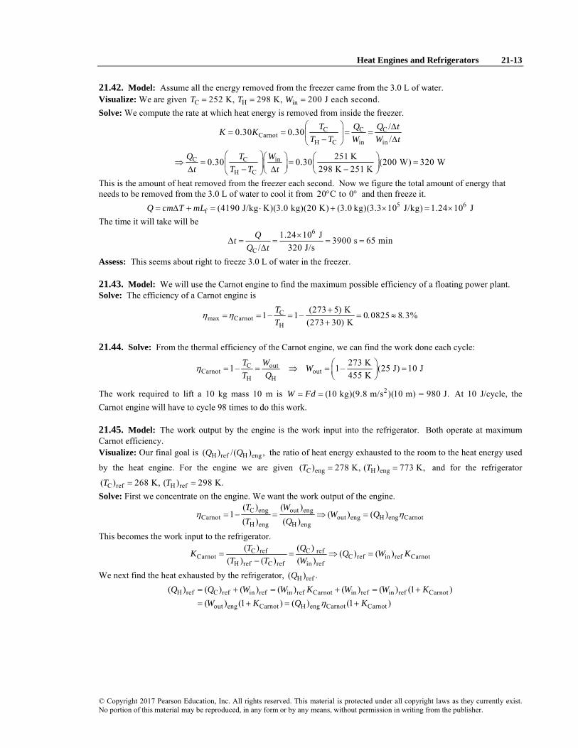
21.42. Model: Assume all the energy removed from the freezer came from the 3.0 L of water. Visualize: We are given C H in252 K, 298 K, 200 J each second.T T W= = = Solve: We compute the rate at which heat energy is removed from inside the freezer.
C C CCarnot
H C in in
C C in
H C
/0.30 0.30/
251 K0.30 0.30 (200 W) 320 W298 K 251 K
T Q Q tK KT T W W t
Q T Wt T T t
⎛ ⎞ Δ= = = =⎜ ⎟
− Δ⎝ ⎠⎛ ⎞⎛ ⎞ ⎛ ⎞⇒ = = =⎜ ⎟⎜ ⎟ ⎜ ⎟Δ − Δ −⎝ ⎠ ⎝ ⎠⎝ ⎠
This is the amount of heat removed from the freezer each second. Now we figure the total amount of energy that needs to be removed from the 3.0 L of water to cool it from 20 C to 0° ° and then freeze it.
5 6f (4190 J/kg K)(3.0 kg)(20 K) (3.0 kg)(3.3 10 J/kg) 1.24 10 JQ cm T mL= Δ + = ⋅ + × = ×
The time it will take will be 6
C
1.24 10 J 3900 s 65 min/ 320 J/s
QtQ t
×Δ = = = =
Δ
Assess: This seems about right to freeze 3.0 L of water in the freezer.
21.43. Model: We will use the Carnot engine to find the maximum possible efficiency of a floating power plant. Solve: The efficiency of a Carnot engine is
Cmax Carnot
H
(273 5) K1 1 0 0825 8 3%(273 30) K
TT
η η += = − = − = . ≈ .
+
21.44. Solve: From the thermal efficiency of the Carnot engine, we can find the work done each cycle:
C outCarnot out
H H
273 K1 1 (25 J) 10 J455 K
T W WT Q
η ⎛ ⎞= − = ⇒ = − =⎜ ⎟⎝ ⎠
The work required to lift a 10 kg mass 10 m is 2(10 kg)(9.8 m/s )(10 m) = 980 J.W Fd= = At 10 J/cycle, the Carnot engine will have to cycle 98 times to do this work.
21.45. Model: The work output by the engine is the work input into the refrigerator. Both operate at maximum Carnot efficiency. Visualize: Our final goal is H ref H eng( ) /( ) ,Q Q the ratio of heat energy exhausted to the room to the heat energy used
by the heat engine. For the engine we are given C eng H eng( ) 278 K, ( ) 773 K,T T= = and for the refrigerator
C ref H ref( ) 268 K, ( ) 298 K.T T= = Solve: First we concentrate on the engine. We want the work output of the engine.
C eng out engCarnot out eng H eng Carnot
H eng H eng
( ) ( )1 ( ) ( )
( ) ( )T W
W QT Q
η η= − = ⇒ =
This becomes the work input to the refrigerator. C ref C ref
Carnot C ref in ref CarnotH ref C ref in ref
( ) ( ) ( ) ( )( ) ( ) ( )
T QK Q W KT T W
= = ⇒ =−
We next find the heat exhausted by the refrigerator, H ref( ) .Q
H ref C ref in ref in ref Carnot in ref in ref Carnot
out eng Carnot H eng Carnot Carnot
( ) ( ) ( ) ( ) ( ) ( ) (1 ) ( ) (1 ) ( ) (1 )Q Q W W K W W K
W K Q Kη= + = + = += + = +

21-14 Chapter 21
© Copyright 2017 Pearson Education, Inc. All rights reserved. This material is protected under all copyright laws as they currently exist. No portion of this material may be reproduced, in any form or by any means, without permission in writing from the publisher.
Now we find our end goal.
( )C engH ref C ref
Carnot CarnotH eng H eng H C refref
C eng H ref
H eng H ref C ref
( )( ) ( )(1 ) 1 1( ) ( ) ( )
( ) ( ) 278 K 298 K 1 1 6.4( ) ( ) ( ) 773 K 298 K 268 K
TQ TKQ T T T
T TT T T
η⎛ ⎞⎛ ⎞⎜ ⎟⎜ ⎟= + = − +⎜ ⎟⎜ ⎟−⎝ ⎠⎝ ⎠
⎛ ⎞⎛ ⎞ ⎛ ⎞⎛ ⎞⎜ ⎟= − = − =⎜ ⎟ ⎜ ⎟⎜ ⎟⎜ ⎟ − −⎝ ⎠⎝ ⎠⎝ ⎠⎝ ⎠
So the refrigerator exhausts 6.4 J into the room for each joule of heat energy used by the heat engine. Assess: Since these are the best possible efficiencies, any real system would be less efficient.
21.46. Solve: (a) 1Q is given as 1000 J. Using the energy transfer equation for the heat engine,
H C out 1 2 out 2 1 outQ Q W Q Q W Q Q W= + ⇒ = + ⇒ = −
The thermal efficiency of a Carnot engine is
C out
H 1
2 1 1 1
300 K1 1 0 50600 K
(1 ) (1000 J)(1 0 50) 500 J
T WT Q
Q Q Q Q
η
η η
= − = − = . =
= − = − = − . =
To determine 3Q and 4,Q we turn our attention to the Carnot refrigerator, which is driven by the output of the heat engine with in out .W W= The coefficient of performance is
C C 4 4
H C in out 1
4 1
400 K 4 0500 K 400 K
(4 0)(0 50)(1000 J) 2000 J
T Q Q QKT T W W Q
Q K Qη
η
= = = . = = =− −
= = . . =
Using now the energy transfer equation in 4 3,W Q Q+ = we have
3 out 4 1 4 (0 50)(1000 J) 2000 J 2500 JQ W Q Q Qη= + = + = . + =
(b) From part (a) 3 2500 JQ = and 1 1000 J,Q = so 3 1.Q Q> (c) Although 1 1000 JQ = and 3 2500 J,Q = the two devices together do not violate the second law of thermodynamics. This is because the hot and cold reservoirs are different for the heat engine and the refrigerator.
21.47. Solve: The work done by the Carnot engine powers the refrigerator, so out Carnot Eng in Refrigerator( ) ( ) .W W= We
are given that H 350 KT = and C = 250 KT for both the Carnot engine and the refrigerator and H Carnot Eng( )Q = 10.0 J for the Carnot engine. The work done by the Carnot engine is
out Carnot EngCout Carnot Eng
H H Carnot Eng
( ) 250 K1 ( ) 1 (10.0 J) 2.857 J( ) 350 KWT W
T Qη ⎛ ⎞= − = ⇒ = − =⎜ ⎟
⎝ ⎠
The heat extracted from the cold reservoir by the refrigerator may be found from its coefficient of performance:
C CC
in Refrigerator out Carnot Eng(2.00)(2.857 J) 5.713 J
( ) ( )Q QK Q
W W= = ⇒ = =
The heat exhausted by the refrigerator to the hot reservoir may be found from the first law of thermodynamics:
in Refrigerator C H H( ) 2.857 J 5.713 J 8.57 JW Q Q Q+ = ⇒ = + =
Assess: The work done on the refrigerator is less than the heat exhausted to the hot reservoir, as expected.

Heat Engines and Refrigerators 21-15
© Copyright 2017 Pearson Education, Inc. All rights reserved. This material is protected under all copyright laws as they currently exist. No portion of this material may be reproduced, in any form or by any means, without permission in writing from the publisher.
21.48. Model: A heat pump is a refrigerator that is cooling the already cold outdoors and warming the indoors with its exhaust heat. Solve: (a) The coefficient of performance for this heat pump is C in5 0 / ,K Q W= . = where CQ is the amount of heat removed from the cold reservoir. HQ is the amount of heat exhausted into the hot reservoir. H C in ,Q Q W= + where
inW is the amount of work done on the heat pump. We have
C in H in in in5 0 5 0 6 0Q W Q W W W= . ⇒ = . + = .
If the heat pump is to deliver 15 kJ of heat per second to the house, then
H in in15 kJ15 kJ 6 0 2 5 kJ
6 0Q W W= = . ⇒ = = .
.
In other words, 2.5 kW of electric power is used by the heat pump to deliver 15 kJ/s of heat energy to the house. (b) The monthly heating cost in the house using an electric heater is
15 kJ 3600 s 1$(200 h) $270s 1 h 40 MJ
⎛ ⎞ ⎛ ⎞⎛ ⎞ =⎜ ⎟ ⎜ ⎟⎜ ⎟⎝ ⎠ ⎝ ⎠⎝ ⎠
The monthly heating cost in the house using a heat pump is
2 5 kJ 3600 s 1$(200 h) $45s 1 h 40 MJ
.⎛ ⎞ ⎛ ⎞⎛ ⎞ =⎜ ⎟ ⎜ ⎟⎜ ⎟⎝ ⎠ ⎝ ⎠⎝ ⎠
21.49. Model: The useful work done by the heat engine changes the kinetic energy of the car; ignore the drag and friction forces. Visualize: For the engine we are given H C1773 K, 293 K.T T= = Solve: First we compute the efficiency
CCarnot
H
293 K0.30 0.30 1 0.30 1 0.251773 K
TT
η η⎛ ⎞ ⎛ ⎞= = − = − =⎜ ⎟ ⎜ ⎟
⎝ ⎠⎝ ⎠
Use the work-kinetic energy theorem: W K= Δ and compute the gas needed to change the kinetic energy of the car. 2 21 1
car 2 2gas
gas gas gas gas
(1500 kg)(30 m/s)57 g
( / ) ( / ) (0.25)(47 kJ/g)mvKm
Q m Q mη ηΔ
= = = =
Assess: The efficiency η is not very high, but gasoline has a lot of energy per gram.
21.50. Model: All of the CQ output by the power plant goes directly into heating homes. Assume the homes are heated steadily for 6 months each year. Visualize: For the engine we are given H C723 K, 303 K.T T= = The 1.0 MW power plant supplies 1.0 MJ each second. Solve: First we compute the efficiency
CCarnot
H
303 K0.65 0.65 1 0.65 1 0.378723 K
TT
η η⎛ ⎞ ⎛ ⎞= = − = − =⎜ ⎟ ⎜ ⎟
⎝ ⎠⎝ ⎠
Now we compute the energy needed by a home in one second—for each second for the six months of heating. 70 GJ 1 y 1 d 1 h 4440 J/s0.5 y 365 d 24 h 3600 s
⎛ ⎞⎛ ⎞⎛ ⎞ =⎜ ⎟⎜ ⎟⎜ ⎟⎝ ⎠⎝ ⎠⎝ ⎠
CQ from the power plant will be used to heat the homes. We compute CQ for one second.
( )outC H out out out
H
C
1 11 1.0 MJ 1 1.65 MJ0.378
per second 1.65 MJ/s#homes 370 homes(energy needed)/home/second 4440 J/s
WQ Q W W WQ
Qη
⎛ ⎞ ⎛ ⎞= − = − = − = − =⎜ ⎟ ⎜ ⎟⎝ ⎠⎝ ⎠
= = =
Assess: This sounds like a reasonable number. Of course there would be many inefficiencies in getting the heat to the homes.

21-16 Chapter 21
© Copyright 2017 Pearson Education, Inc. All rights reserved. This material is protected under all copyright laws as they currently exist. No portion of this material may be reproduced, in any form or by any means, without permission in writing from the publisher.
21.51. Model: The power plant is to be treated as a heat engine. Solve: (a) Every hour 300 metric tons or 53 10 kg× of coal is burnt. The volume of coal is
5 333 10 kg m (24 h) 4800 m
1 h 1500 kg⎛ ⎞⎛ ⎞×
=⎜ ⎟⎜ ⎟⎜ ⎟⎜ ⎟⎝ ⎠⎝ ⎠
The height of the room will be 48 m. (b) The thermal efficiency of the power plant is
8 8out
95 6H
7 50 10 J/s 7 50 10 J 0 32 32%2 333 10 J3 10 kg 28 10 J 1 h
1 h kg 3600 s
WQ
η . × . ×= = = = . =
⎛ ⎞⎛ ⎞ . ×× × ⎛ ⎞⎜ ⎟⎜ ⎟⎜ ⎟⎜ ⎟⎜ ⎟⎝ ⎠⎝ ⎠⎝ ⎠
Assess: An efficiency of 32% is typical of power plants.
21.52. Model: The power plant is treated as a heat engine. Solve: We are given that H 300°C 573 KT = = and C 25°C 298 K.T = = (a) The maximum possible thermal efficiency of the power plant is
Cmax
H
298 K1 1 0 48 48%573 K
TT
η = − = − = . =
(b) In one second, the plant generates 6out 1000 10 JW = × of work and 6
H 3000 10 JQ = × of heat energy to replace the energy taken from the hot reservoir to heat the water. The plant’s actual efficiency is
6out
6H
1000 10 J 0 33 33%3000 10 J
WQ
η ×= = . =
×
(c) Because H C out ,Q Q W= +
9 9 9C H out C 3 0 10 J/s 1 0 10 J/s 2 0 10 J/sQ Q W Q= − ⇒ = . × − . × = . ×
The mass of water that flows per second through the condenser is 3 3
8 43
L 1 hr 10 m 1000 kg1 2 10 (1s) 3 333 10 kgh 3600 s 1 L m
m−⎛ ⎞⎛ ⎞⎛ ⎞ ⎛ ⎞= . × = . ×⎜ ⎟⎜ ⎟⎜ ⎟ ⎜ ⎟⎜ ⎟⎝ ⎠⎝ ⎠ ⎝ ⎠⎝ ⎠
The change in the temperature as 9C 2 0 10 JQ = . × of heat is transferred to 43 333 10 kgm = . × of water is
9 4C 2 0 10 J (3 333 10 kg)(4186 J/kg K) 14 CQ mc T T T= Δ ⇒ . × = . × Δ ⇒ Δ = °
The exit temperature is 18°C 14°C 32°C.+ = Assess: A temperature increase of 14 °C would certainly affect wildlife in and around the river!
21.53. Model: The power plant is treated as a heat engine. Solve: The mass of water per second that flows through the plant every second is
3 38 4
3L 1 hr 10 m 1000 kg1 0 10 2 778 10 kg/sh 3600 s 1 L m
m−⎛ ⎞⎛ ⎞⎛ ⎞ ⎛ ⎞= . × = . ×⎜ ⎟⎜ ⎟⎜ ⎟ ⎜ ⎟⎜ ⎟⎝ ⎠⎝ ⎠ ⎝ ⎠⎝ ⎠
The amount of heat transferred per second to the cooling water is thus 4 9
C (2 778 10 kg/s)(4186 J/kg K)(27 C 16 C) 1 279 10 J/sQ mc T= Δ = . × ° − ° = . ×
The amount of heat per second input into the power plant is 9 9 9
H out C 0 750 10 J/s 1 279 10 J/s 2 029 10 J/sQ W Q= + = . × + . × = . ×
Heat Engines and Refrigerators 21-17
© Copyright 2017 Pearson Education, Inc. All rights reserved. This material is protected under all copyright laws as they currently exist. No portion of this material may be reproduced, in any form or by any means, without permission in writing from the publisher.
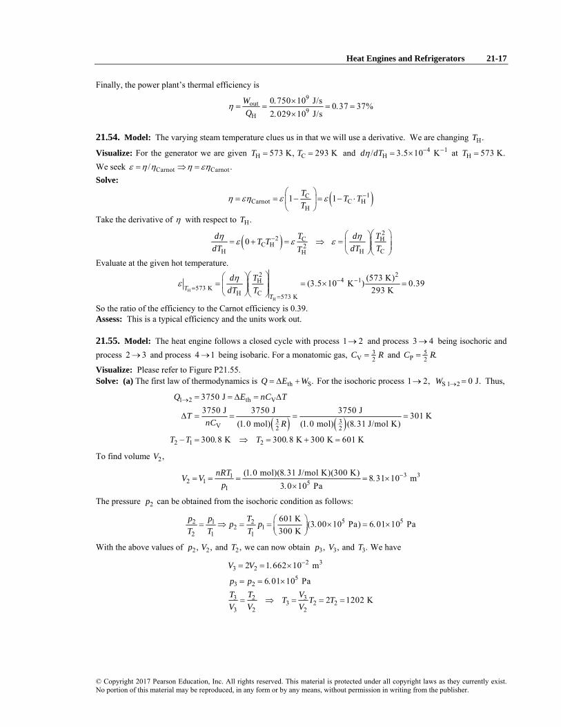
Finally, the power plant’s thermal efficiency is 9
out9
H
0 750 10 J/s 0 37 37%2 029 10 J/s
WQ
η . ×= = = . =
. ×
21.54. Model: The varying steam temperature clues us in that we will use a derivative. We are changing H.T
Visualize: For the generator we are given H C573 K, 293 KT T= = and 4 1H/ 3.5 10 Kd dTη − −= × at H 573 K.T =
We seek Carnot Carnot/ .ε η η η εη= ⇒ = Solve:
( )1CCarnot C H
H1 1T T T
Tη εη ε ε −⎛ ⎞
= = − = − ⋅⎜ ⎟⎝ ⎠
Take the derivative of η with respect to H.T
( )2
2 C HC H 2
H H CH0 d T d TT T
dT dT TTη ηε ε ε− ⎛ ⎞⎛ ⎞
= + = ⇒ = ⎜ ⎟⎜ ⎟⎜ ⎟⎝ ⎠⎝ ⎠
Evaluate at the given hot temperature.
H
H
2 24 1H
573 KH C 573 K
(573 K)(3.5 10 K ) 0.39293 KT
T
d TdT T
ηε − −=
=
⎛ ⎞⎛ ⎞= = × =⎜ ⎟⎜ ⎟⎜ ⎟⎝ ⎠⎝ ⎠
So the ratio of the efficiency to the Carnot efficiency is 0.39. Assess: This is a typical efficiency and the units work out.
21.55. Model: The heat engine follows a closed cycle with process 1 2→ and process 3 4→ being isochoric and process 2 3→ and process 4 1→ being isobaric. For a monatomic gas, 3
V 2C R= and 5P 2C R= .
Visualize: Please refer to Figure P21.55. Solve: (a) The first law of thermodynamics is th S.Q E W= Δ + For the isochoric process 1 2,→ S 1 2 0 J.W → = Thus,
( ) ( )
1 2 th V
3 3V 2 2
2 1 2
3750 J3750 J 3750 J 3750 J 301 K
(1 0 mol) (1 0 mol) (8 31 J/mol K)
300 8 K 300 8 K 300 K 601 K
Q E nC T
TnC R
T T T
→ = = Δ = Δ
Δ = = = =. . .
− = . ⇒ = . + =
To find volume 2,V
3 312 1 5
1
(1 0 mol)(8 31 J/mol K)(300 K) 8 31 10 m3 0 10 Pa
nRTV Vp
−. .= = = = . ×
. ×
The pressure 2p can be obtained from the isochoric condition as follows:
5 52 1 22 1
2 1 1
601 K (3 00 10 Pa) 6 01 10 Pa300 K
p p Tp pT T T
⎛ ⎞= ⇒ = = . × = . ×⎜ ⎟⎝ ⎠
With the above values of 2 2, ,p V and 2,T we can now obtain 3,p 3,V and 3.T We have
2 33 2
53 2
3 2 33 2 2
3 2 2
2 1 662 10 m
6 01 10 Pa
2 1202 K
V V
p pT T VT T TV V V
−= = . ×
= = . ×
= ⇒ = = =

21-18 Chapter 21
© Copyright 2017 Pearson Education, Inc. All rights reserved. This material is protected under all copyright laws as they currently exist. No portion of this material may be reproduced, in any form or by any means, without permission in writing from the publisher.
For the isobaric process 2 3,→
( ) ( )5 52 3 P 3 22 2
5 3 3S 2 3 3 3 2
th 2 3 S 2 3
(1 0 mol) ( ) (1 0 mol) (8 31 J/mol K)(601 K) 12,480 J
( ) (6 01 10 Pa)(8 31 10 m ) 4990 J12,480 J 4990 J 7490 J
Q nC T R T T
W p V VE Q W
→
−→
→ →
= Δ = . − = . . =
= − = . × . × =
Δ = − = − =
We are now able to obtain 4,p 4,V and 4.T We have
2 34 3
54 1
54 3 4
4 3 54 3 3
1 662 10 m
3 00 10 Pa
3 00 10 Pa (1202 K) 600 K6 01 10 Pa
V V
p p
T T pT Tp p p
−= = . ×
= = . ×
⎛ ⎞. ×= ⇒ = = =⎜ ⎟⎜ ⎟. ×⎝ ⎠
For isochoric process 3 4,→
( ) ( )3 33 4 V 4 32 2
S 3 4 th 3 4 S 3 4
(1 0 mol) ( ) (1 0 mol) (8 31 J/mol K)( 602) 7500 J
0 J 7500 J
Q nC T R T T
W E Q W→
→ → →
= Δ = . − = . . − = −
= ⇒ Δ = − = −
For isobaric process 4 1,→ 5
4 1 P 25 3 3 2 3
S 4 1 4 1 4
th 4 1 S 4 1
(1 0 mol) (8 31 J/mol K)(300 K 600 K) 6230 J
( ) (3 00 10 Pa) (8 31 10 m 1 662 10 m ) 2490 J6230 J ( 2490 J) 3740 J
Q nC T
W p V VE Q W
→
− −→
→ →
= Δ = . . − = −
= − = . × × . × − . × = −
Δ = − = − − − = −
S (J)W Q (kJ) th (kJ)EΔ 1 2→ 0 3750 3750 2 3→ 4990 12,480 7490 3 4→ 0 –7500 –7500 4 1→ –2490 –6230 –3740 Net 2500 2500 0
(b) The thermal efficiency of this heat engine is
out out
H 1 2 2 3
2500 J 0 15 15%3750 J 12,480 J
W WQ Q Q
η→ →
= = = = . =+ +
Assess: Note that more than two significant figures are retained in part (a) because the results are intermediate. For a closed cycle, as expected, s net net( )W Q= and th net( ) 0 JEΔ =
21.56. Model: The heat engine follows a closed cycle. For a diatomic gas, 5V 2C R= and 7
P 2C R= .
Visualize: Please refer to Figure P21.56. Solve: (a) Since 1 293 K,T = the number of moles of the gas is
5 6 341 1
1
(0 5 1 013 10 Pa)(10 10 m ) 2 08 10 mol(8 31 J/mol K)(293 K)
p VnRT
−−. × . × ×
= = = . ×.
At point 2, 2 1 2 14 and 3 .V V p p= = The temperature is calculated as follows:
1 1 2 2 2 22 1
1 2 1 1(3)(4)(293 K) 3516 Kp V p V p VT T
T T p V= ⇒ = = =
At point 3, 3 2 1 3 14 and .V V V p p= = = The temperature is calculated as before:
3 33 1
1 1(1)(4)(293 K) 1172 Kp VT T
p V= = =

Heat Engines and Refrigerators 21-19
© Copyright 2017 Pearson Education, Inc. All rights reserved. This material is protected under all copyright laws as they currently exist. No portion of this material may be reproduced, in any form or by any means, without permission in writing from the publisher.
For process 1 2,→ the work done is the area under the p-versus-V curve. That is, 3 3 3 31
s 25
6 3
(0 5 atm)(40 cm 10 cm ) (1 5 atm 0 5 atm)(40 cm 10 cm )
1 013 10 Pa(30 10 m )(1 atm) 3 04 J1 atm
W
−
= . − + . − . −
⎛ ⎞. ×= × = .⎜ ⎟⎜ ⎟
⎝ ⎠
The change in the thermal energy is 4 5
th V 2(2 08 10 mol) (8 31 J/mol K)(3516 K 293 K) 13 93 JE nC T −Δ = Δ = . × . − = .
The heat is s th 16 97 J.Q W E= + Δ = . For process 2 3,→ the work done is s 0 JW = and
( )5th V 3 22
4 52
( )
(2 08 10 mol) (8 31 J/mol K)(1172 K 3516 K) 10 13 J
Q E nC T n R T T−
= Δ = Δ = −
= . × . − = − .
For process 3 1,→ 3 3 5 6 3
s4 5
th V 2
(0 5 atm)(10 cm 40 cm ) (0 5 1 013 10 Pa)( 30 10 m ) 1 52 J
(2 08 10 mol) (8 31 J/mol K)(293 K 1172 K) 3 80 J
W
E nC T
−
−
= . − = . × . × − × = − .
Δ = Δ = . × . − = − .
The heat is th s 5 32 J.Q E W= Δ + = − .
s (J)W Q (J) thEΔ
1 2→ 3.04 16.97 13.93 2 3→ 0 −10.13 −10.13 3 1→ −1.52 −5.32 −3.80 Net 1.52 1.52 0
(b) The efficiency of the engine is
net
H
1 52 J 0 090 9 0%16 97 J
WQ
η .= = = . = .
.
(c) The power output of the engine is
netrevolutions 1 min 500500 (1 52 J/s) 13 Wmin 60 s revolution 60
W⎛ ⎞⎛ ⎞⎛ ⎞ ⎛ ⎞= . =⎜ ⎟⎜ ⎟⎜ ⎟ ⎜ ⎟⎝ ⎠⎝ ⎠⎝ ⎠ ⎝ ⎠
Assess: Note that more than two significant figures are retained in part (a) because the results are intermediate. For a closed cycle, as expected, s net net( )W Q= and th net( ) 0 J.EΔ =
21.57. Model: For the closed cycle, process 1 2→ is isothermal, process 2 3→ is isobaric, and process 3 1→ is isochoric. Visualize: Please refer to Figure P21.57. Solve: (a) We first need to find the conditions at points 1, 2, and 3. We can then use that information to find SW and Q for each of the three processes that make up this cycle. Using the ideal-gas equation the number of moles of the gas is
5 6 31 1
1
(1 013 10 Pa)(600 10 m ) 0 0244 mol(8 31 J/mol K)(300 K)
p VnRT
−. × ×= = = .
.
We are given that 1.25,γ = which means this is not a monatomic or a diatomic gas. The specific heats are
V P V4 51
RC R C C R Rγ
= = = + =−

21-20 Chapter 21
© Copyright 2017 Pearson Education, Inc. All rights reserved. This material is protected under all copyright laws as they currently exist. No portion of this material may be reproduced, in any form or by any means, without permission in writing from the publisher.
At point 2, process 1 2→ is isothermal, so we can find the pressure 2p as follows:
4 351
1 1 2 2 2 1 1 14 32
6 00 10 m 3 3 atm 3 039 10 Pa2 00 10 m
Vp V p V p p p pV
−
−. ×
= ⇒ = = = = = . ×. ×
At point 3, process 2 3→ is isobaric, so we can find the temperature 3T as follows:
4 32 3 3
3 2 2 24 32 3 2
6 00 10 m 3 900 K2 00 10 m
V V VT T T TT T V
−
−. ×
= ⇒ = = = =. ×
Point P (Pa) 3(m )V T (K)
1 51.0 atm 1.013 10= × 46.00 10−× 300 2 53.0 atm 3.039 10= × 42.00 10−× 300 3 53.0 atm 3.039 10= × 46.00 10−× 900
Process 1 2→ is isothermal:
S 12 1 1 2 1( ) ln( / ) 66 8 JW p V V V= = − . 12 S 12( ) 66 8 JQ W= = − .
Process 2 3→ is isobaric:
S 23 2 2 3 2( ) ( ) 121 6 JW p V p V V= Δ = − = . 23 P P 3 2( ) 608 3 JQ nC T nC T T= Δ = − = .
Process 3 1→ is isochoric:
S 31( ) 0 JW = 31 V V 1 3( ) 486 7 JQ nC T nC T T= Δ = − = − .
We find that
S cycle( ) 66 8 J 121 6 J 0 J 54 8 JW = − . + . + = . cycle 66 8 J 608 3 J 486 7 J 54 8 JQ = − . + . − . = .
These are equal, as they should be. Knowing that the work done is out S cycle( ) 54.8 J/cycle,W W= = an engine operating at 20 cycles/s has a power output of
out54 8 J 20 cycle J1096 1096 W 1 10 kWcycle s s
P⎛ ⎞. ⎛ ⎞= = = ≈ .⎜ ⎟⎜ ⎟
⎝ ⎠⎝ ⎠
(b) Only 23Q is positive, so in 23 608 J.Q Q= = Thus, the thermal efficiency is
out
in
54 8 J 0 0901 9 01%608 3 J
WQ
η .= = = . = .
.
21.58. Model: For the closed cycle of the heat engine, process 1 2→ is isobaric, process 2 3→ is isochoric, and process 3 1→ is adiabatic. 3
V 2C R= and 5P 2C R= for a monatomic gas, so 5/3.γ =
Visualize: Please refer to Figure P21.58. Solve: (a) We can use the adiabat 3 1→ to calculate 1p as follows:
5/333
1 3 1 31 3 31
600 cm(100 kPa) 1981 kPa100 cm
Vp V p V p pV
γγ γ ⎛ ⎞⎛ ⎞
= ⇒ = = =⎜ ⎟⎜ ⎟ ⎜ ⎟⎝ ⎠ ⎝ ⎠
1T can be determined by taking the ratio of the ideal-gas equation applied to points 1 and 2. This gives
1 1 1
2 2 23
11 2 3
2
100 cm(600 K) 100 K600 cm
p V Tp V T
VT TV
=
= = =
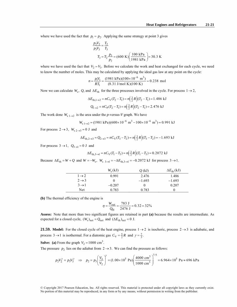
Heat Engines and Refrigerators 21-21
© Copyright 2017 Pearson Education, Inc. All rights reserved. This material is protected under all copyright laws as they currently exist. No portion of this material may be reproduced, in any form or by any means, without permission in writing from the publisher.
where we have used the fact that 1 2.p p= Applying the same strategy at point 3 gives
2 2 2
3 3 3
33 2
2
100 kPa(600 K) 30 3 K1981 kPa
p V Tp V T
pT Tp
=
⎛ ⎞= = = .⎜ ⎟⎝ ⎠
where we have used the fact that 2 3.V V= Before we calculate the work and heat exchanged for each cycle, we need to know the number of moles. This may be calculated by applying the ideal gas law at any point on the cycle:
6 31 1
1
(1981 kPa)(100 10 m ) 0.238 mol(8.31 J/mol K)(100 K)
p VnRT
−×= = =
Now we can calculate s ,W Q, and thEΔ for the three processes involved in the cycle. For process 1 2,→
( )( )
3th,1 2 V 2 1 2 12
51 2 P 2 1 2 12
( ) ( ) 1 486 kJ
( ) ( ) 2 476 kJ
E nC T T n R T T
Q nC T T n R T T
→
→
Δ = − = − = .
= − = − = .
The work done s 1 2W → is the area under the p-versus-V graph. We have
6 3 6 3s 1 2 (1981 kPa)(600 10 m 100 10 m ) 0 991 kJW − −
→ = × − × = .
For process 2 3,→ s 2 3 0 JW → = and
( )3th,2 3 2 3 V 3 2 3 22( ) ( ) 1 693 kJE Q nC T T n R T T→ →Δ = = − = − = − .
For process 3 1,→ 3 1 0 JQ → = and
( )3th,3 1 V 1 3 1 32( ) ( ) 0 2072 kJE nC T T n R T T→Δ = − = − = .
Because thE W QΔ = + and s ,W W= − s 3 1 th,3 1 0 2072 kJW E→ →= −Δ = − . for process 3 1.→
s (kJ)W Q (kJ) th (kJ)EΔ 1 2→ 0.991 2.476 1.486 2 3→ 0 −1.693 −1.693 3 1→ −0.207 0 0.207 Net 0.783 0.783 0
(b) The thermal efficiency of the engine is
out
H
783 J 0 32 32%2476 J
WQ
η = = = . =
Assess: Note that more than two significant figures are retained in part (a) because the results are intermediate. As expected for a closed cycle, s net net( )W Q= and th net( ) 0 J.EΔ =
21.59. Model: For the closed cycle of the heat engine, process 1 2→ is isochoric, process 2 3→ is adiabatic, and process 3 1→ is isothermal. For a diatomic gas 5
V 2C R= and 75 .γ =
Solve: (a) From the graph 32 1000 cm .V =
The pressure 2p lies on the adiabat from 2 3.→ We can find the pressure as follows:
7/535 53
2 3 2 32 3 32
4000 cm(1 00 10 Pa) 6 964 10 Pa 696 kPa1000 cm
Vp V p V p pV
γγ γ ⎛ ⎞⎛ ⎞
= ⇒ = = . × = . × ≈⎜ ⎟⎜ ⎟ ⎜ ⎟⎝ ⎠ ⎝ ⎠

21-22 Chapter 21
© Copyright 2017 Pearson Education, Inc. All rights reserved. This material is protected under all copyright laws as they currently exist. No portion of this material may be reproduced, in any form or by any means, without permission in writing from the publisher.
The temperature 2T can be obtained from the ideal-gas equation relating points 1 and 2:
51 1 2 2 2 2
2 1 51 2 1 1
6 964 10 Pa(300 K) (1) 522 3 K 522 K4 00 10 Pa
p V p V p VT TT T p V
⎛ ⎞. ×= ⇒ = = = . ≈⎜ ⎟⎜ ⎟. ×⎝ ⎠
(b) The number of moles of the gas is 5 3 3
1 1
1
(4 00 10 Pa)(1 00 10 m ) 0 1604 mol(8 31 J/mol K)(300 K)
p VnRT
−. × . ×= = = .
.
For isochoric process s1 2, 0 JW→ = and
( )5th V 2 741 1 JQ E nC T n R T= Δ = Δ = Δ = .
For adiabatic process 2 3, 0 JQ→ = and
( )5th V 3 22 ( ) 741 1 JE nC T n R T TΔ = Δ = − = − .
Using the first law of thermodynamics, th s ,E W QΔ = + which means s th 741.1 J.W E= −Δ = + sW can also be determined from
( )( )
433 3 2 2 3 2
s 25
J/K (300 K 522 3 K)( ) 741 1 J1 1
p V p V nR T TWγ γ
− .− −= = = = .
− − −
For isothermal process 3 1,→ th 0 JEΔ = and
1s 1
3ln 554 5 JVW nRT
V= = − .
Using the first law of thermodynamics, th s ,E W QΔ = − + s 554 5 J.Q W= = − .
th (J)EΔ s (J)W Q (J) 1 2→ 741.1 0 741.1 2 3→ −741.1 741.1 0 3 1→ 0 −554.5 −554.5 Net 0 186.6 186.6
(c) The work per cycle is 187 J and the thermal efficiency is
s
H
186 6 J 0 25 25%741 1 J
WQ
η .= = = . =
.
21.60. Model: Processes 2 → 1 and 4 → 3 are isobaric. Processes 3 → 2 and 1 → 4 are isochoric. Visualize:
Solve: (a) Except in an adiabatic process, heat must be transferred into the gas to raise its temperature. Thus heat is transferred in during processes 4 → 3 and 3 → 2. This is the reverse of the heat engine in Example 21.2.

Heat Engines and Refrigerators 21-23
© Copyright 2017 Pearson Education, Inc. All rights reserved. This material is protected under all copyright laws as they currently exist. No portion of this material may be reproduced, in any form or by any means, without permission in writing from the publisher.
(b) Heat flows from hot to cold. Since heat energy is transferred into the gas during processes 4 → 3 and 3 → 2, which end with the gas at temperature 2700 K, the reservoir temperature must be T > 2700 K. This is the hot reservoir, so the heat transferred is H.Q Similarly, heat energy is transferred out of the gas during processes 2 → 1 and 1 → 4. This requires that the reservoir temperature be T < 300 K. This is the cold reservoir, and the energy transferred during these two processes is C.Q (c) The heat energies were calculated in Example 21.2, but now they have the opposite signs.
5 5 5H 43 32
5 5 5C 21 14
7.09 10 J 15.19 10 J 22.28 10 J
21.27 10 J 5.06 10 J 26.33 10 J
Q Q Q
Q Q Q
= + = × + × = ×
= + = × + × = ×
(d) For a counterclockwise cycle in the pV diagram, the work is in.W Its value is the area inside the curve, which is inW = 3 5( ) 2 101,300 Pa (2 m ) 4.05 10 J.p V(Δ ) Δ = ( × ) = × Note that in C ,W Q QΗ= − as expected from energy conservation.
(e) No. A refrigerator uses work input to transfer heat energy from the cold reservoir to the hot reservoir. This device uses work input to transfer heat energy from the hot reservoir to the cold reservoir.
21.61. Model: Process 1 → 2 of the cycle is isochoric, process 2 → 3 is isothermal, and process 3 → 1 is isobaric. For a monatomic gas, 3
V 2C R= and 5P 2 RC = .
Visualize: Please refer to Figure P21.61. Solve: (a) At point 1, the pressure 5
1 1 atm 1.013 10 Pap = = × and the volume 6 3 3 31 1000 10 m 1 10 m .V − −= × = ×
The number of moles is
0 120 g 0 03 mol4 g/mol
n .= = .
Using the ideal-gas law, 5 3 3
1 11
(1 013 10 Pa)(1 0 10 m ) 406 K 0 4 kK(0 030 mol)(8 31 J/mol K)
p VTnR
−. × . ×= = = ≈ .
. .
At point 2, the pressure 52 5 atm 5 06 10 Pap = = . × and 3 3
2 1 10 m .V −= × The temperature is
5 3 32 2
2(5 06 10 Pa)(1 0 10 m ) 2030 K 2 kK
(0 030 mol)(8 31 J/mol K)p VTnR
−. × . ×= = = ≈
. .
At point 3, the pressure is 53 1 atm 1 013 10 Pap = = . × and the temperature is 3 2 2030 K.T T= = The volume is
3 3 3 323 2
3
5 atm(1 10 m ) 5 10 m1 atm
pV Vp
− −⎛ ⎞= = × = ×⎜ ⎟⎝ ⎠
(b) For the isochoric process 1 → 2, W1→2 = 0 J and
( )31 2 V 2(0.030 mol) (2030 K 406 K) 607 JQ nC T R→ = Δ = − =
For the isothermal process 2 → 3, th 2 3 0 JE →Δ = and
3 33
2 3 2 3 2 3 32
5 0 10 mln (0 030 mol)(8 31 J/mol K)(2030 K)ln 815 J1 0 10 m
VQ W nRTV
−
→ → −
⎛ ⎞. ×= = = . . =⎜ ⎟⎜ ⎟. ×⎝ ⎠
For the isobaric process 3 → 1,
( )5 3 3 3 3
3 1 35
3 1 P 2
(1 013 10 Pa)(1 0 10 m 5 0 10 m ) 405 J
(0.030 mol) (8.31 J/mol K)(406 K 2030 K) 1012 J
W p V
Q nC T
− −→
→
= Δ = . × . × − . × = −
= Δ = − = −
The total work done is net 1 2 2 3 3 1 410 J.W W W W→ → →= + + = The total heat input is H 1 2 2 3 1422 J.Q Q Q→ →= + = The thermal efficiency of the engine is

21-24 Chapter 21
© Copyright 2017 Pearson Education, Inc. All rights reserved. This material is protected under all copyright laws as they currently exist. No portion of this material may be reproduced, in any form or by any means, without permission in writing from the publisher.
net
H
410 J 29,1422 J
WQ
η = = =
(c) The maximum possible efficiency of a heat engine that operates between Tmax and Tmin is
minmax
max
406 K1 1 80,2030 K
TT
η = − = − =
Assess: The actual efficiency of an engine is less than the maximum possible efficiency.
21.62. Model: The process 2 → 3 of the heat engine cycle is isochoric and the process 3 → 1 is isobaric. For a monatomic gas 3
V 2C R= and 5P 2 .C R=
Solve: (a) The three temperatures are 5 3
1 11
5 32 2
2
5 33 3
3
(4.0 10 Pa)(0.025 m ) 601.7 K 0.60 kK(2.0 mol)(8.31 J/mol K)
(6.0 10 Pa)(0.050 m ) 1805.1 K 1.8 kK(2.0 mol)(8.31 J/mol K)
(4.0 10 Pa)(0.050 m ) 1203.4 K 1.2 kK(2.0 mol)(8.31 J/mol K)
p VTnR
p VTnR
p VTnR
×= = = ≈
×= = = ≈
×= = = ≈
(b) For process 1 → 2, the work done is the area under the p-versus-V graph. The work and the change in internal energy are
( )( )
5 5 3 3 5 3 31s 2
4
3th V 2 12
432
(6.0 10 Pa 4.0 10 Pa)(0.050 m 0.025 m ) (4.0 10 Pa)(0.050 m 0.025 m )
1.25 10 J
(2.0 mol) ( )
(2.0 mol) (8.31 J/mol K)(1805.1 K 601.7 K) 3.00 10 J
W
E nC T R T T
= × − × − + × −
= ×
Δ = Δ = −
= − = ×
The heat input is 4s th 4.25 10 J.Q W E= + Δ = × For isochoric process 2 → 3, s 0 JW = and
43th V 2(2.0 mol) (8.31 J/mol K)(1203.4 K 1805.1 K) 1.50 10 JQ E nC T= Δ = Δ = − = − ×
For isobaric process 3 → 1, the work done is the area under the p-versus-V curve. Hence,
( )5 3 3 4
s43 3
th V 1 32 2
(4.0 10 Pa)(0.025 m 0.050 m ) 1.0 10 J
( ) (2.0 mol) (8.31 J/mol K)(601.7 K 1203.4 K) 1.5 10 J
W
E nC T n R T T
= × − = − ×
Δ = Δ = − = − = − ×
The heat input is 4S th 2.50 10 J.Q W E= + Δ = − ×
th (J)EΔ S (J)W Q (J)
1 → 2 43.0 10× 41.25 10× 44.25 10× 2 → 3 4. 10−1 5× 0 41.50 10− × 3 → 1 4. 10−1 5× 4.0 10−1 × 42.50 10− × Net 0 32.5 10× 32.5 10×
(c) The thermal efficiency is 3
net4
H
2.5 10 J 5.9,4.25 10 J
WQ
η ×= = =
×

Heat Engines and Refrigerators 21-25
© Copyright 2017 Pearson Education, Inc. All rights reserved. This material is protected under all copyright laws as they currently exist. No portion of this material may be reproduced, in any form or by any means, without permission in writing from the publisher.
21.63. Model: The closed cycle in this heat engine includes adiabatic process 1 → 2, isobaric process 2 → 3, and isochoric process 3 → 1. For a diatomic gas, 5 7 7
V P2 2 5, , and 1.4.C R C R γ= = = =
Visualize: Please refer to Figure P21.63. Solve: (a) We can find the temperature 2T from the ideal-gas equation as follows:
5 3 32 2
2(4.0 10 Pa)(1.0 10 m ) 2407 K 2.4 kK(0.020 mol)(8.31 J/mol K)
p VTnR
−× ×= = = ≈
We can use the equation 2 12 1p V p Vγ γ= to find 1,V
1 1.41 53 3 3 32
1 2 51
4.0 10 Pa(1.0 10 m ) 2.692 10 m1.0 10 Pa
pV Vp
γ //− −⎛ ⎞⎛ ⎞ ×
= = × = ×⎜ ⎟⎜ ⎟ ⎜ ⎟×⎝ ⎠ ⎝ ⎠
The ideal-gas equation can now be used to find 1,T 5 3 3
1 11
(1.0 10 Pa)(2.692 10 m ) 1620 K 1.6 kK(0.020 mol)(8.31 J/mol K)
p VTnR
−× ×= = = ≈
At point 3, 3 1V V= so we have
5 3 33 3
3(4 10 Pa)(2.692 10 m ) 6479 K 6.5 kK
(0.020 mol)(8.31 J/mol K)p VTnR
−× ×= = = ≈
(b) For adiabatic process 1 → 2, Q = 0 J, th s ,E WΔ = − and
2 2 1 1 2 1s
( ) (0.020 mol)(8.31 J/mol K)(2407 K 1620 K) 327.0 J1 1 (1 1.4)
p V p V nR T TWγ γ
− − −= = = = −
− − −
For isobaric process 2 → 3,
( )( )
7 7P 2 2
5th V 2
( ) (0.020 mol) (8.31 J/mol K)(6479 K 2407 K) 2369 J
1692 J
Q nC T n R T
E nC T n R T
= Δ = Δ = − =
Δ = Δ = Δ =
The work done is the area under the p-versus-V graph. Hence, 5 3 3 3 3
s (4.0 10 Pa)(2.692 10 m 1.0 10 m ) 677 JW − −= × × − × =
For isochoric process 3 → 1, s 0 JW = and
( )5th V 2(0.020 mol) (8.31 J/mol K)(1620 K 6479 K) 2019 JE Q nC TΔ = = Δ = − = −
th (J)EΔ S (J)W Q (J) 1 → 2 327 −327 0 2 → 3 1692 677 2369 3 → 1 −2019 0 −2019 Net 0 350 350
(c) The engine’s thermal efficiency is
net
H
350 J 0.15 15,2369 J
WQ
η = = = =

21-26 Chapter 21
© Copyright 2017 Pearson Education, Inc. All rights reserved. This material is protected under all copyright laws as they currently exist. No portion of this material may be reproduced, in any form or by any means, without permission in writing from the publisher.
21.64. Model: The closed cycle of the heat engine involves the following four processes: isothermal expansion, isochoric cooling, isothermal compression, and isochoric heating. For a monatomic gas 3
V 2 .C R=
Visualize:
Solve: Using the ideal-gas law, 51
1 3 31
(0.20 mol)(8.31 J/mol K)(600 K) 4.986 10 Pa2.0 10 m
nRTpV −= = = ×
×
At point 2, because of the isothermal conditions, 2 1 600 KT T= = and
3 35 51
2 1 3 32
2.0 10 m(4.986 10 Pa) 2.493 10 Pa4.0 10 m
Vp pV
−
−
⎛ ⎞×= = × = ×⎜ ⎟⎜ ⎟×⎝ ⎠
At point 3, because it is an isochoric process, 33 2 4000 cmV V= = and
5 533 2
2
300 K(2.493 10 Pa) 1.247 10 Pa600 K
Tp pT
⎛ ⎞= = × = ×⎜ ⎟
⎝ ⎠
Likewise at point 4, 4 3 300 KT T= = and
3 35 53
4 3 3 34
4.0 10 m(1.247 10 Pa) 2.493 10 Pa2.0 10 m
Vp pV
−
−
⎛ ⎞×= = × = ×⎜ ⎟⎜ ⎟×⎝ ⎠
Let us now calculate net 1 2 2 3 3 4 4 1.W W W W W→ → → →= + + + For the isothermal processes,
( )
21 2 1
1
4 13 4 3 2
3
ln (0.20 mol)(8.31 J/mol K)(600 K)ln(2) 691.2 J
ln (0.20 mol)(8.31 J/mol K)(300 K)ln 345.6 J
VW nRTVVW nRTV
→
→
= = =
= = = −
For the isochoric processes, 2 3 4 1 0 J.W W→ →= = Thus, the work done per cycle is net 345.6 J 350 J.W = ≈ Because
S th ,Q W E= + Δ
1 2 1 2 th 1 2( ) 691.2 J 0 J 691.2 JQ W E→ → →= + Δ = + =
For the first isochoric process,
( )32 3 V 3 22
32
(0.20 mol) ( )
(0.20 mol) (8.31 J/mol K)(300 K 600 K) 747.9 K
Q nC T R T T→ = Δ = −
= − = −

Heat Engines and Refrigerators 21-27
© Copyright 2017 Pearson Education, Inc. All rights reserved. This material is protected under all copyright laws as they currently exist. No portion of this material may be reproduced, in any form or by any means, without permission in writing from the publisher.
For the second isothermal process
3 4 3 4 th 3 4( ) 345.6 J 0 J 345.6 JQ W E→ → →= + Δ = − + = −
For the second isochoric process,
( )( )
34 1 V 1 42
32
( )
(0.20 mol) (8.31 J/mol K)(600 K 300 K) 747.9 K
Q nC T n R T T→ = Δ = −
= − =
Thus, H 1 2 4 1 1439.1 J.Q Q Q→ →= + = The thermal efficiency of the engine is
net
H
345.6 J 0.24 24,1439.1 J
WQ
η = = = =
21.65. Solve: (a) If you wish to build a Carnot engine that is 80% efficient and exhausts heat into a cold reservoir at 0°C, what temperature (in °C) must the hot reservoir be? (b)
3H
H H
(0 C 273) 2730.80 1 0.20 1.1 10 C( 273) 273
TT T° +
= − ⇒ = ⇒ = × °+ +
21.66. Solve: (a) A refrigerator with a coefficient of performance of 4.0 exhausts 100 J of heat in each cycle. What work is required each cycle and how much heat is removed each cycle from the cold reservoir? (b) We have C in C in4.0 / 4 .Q W Q W= ⇒ = This means
HH C in in in in in
100 J4 5 20 J5 5
QQ Q W W W W W= + = + = ⇒ = = =
Hence, C H in 100 J 20 J 80 J.Q Q W= − = − =
21.67. Solve: (a) A heat engine operates at 20% efficiency and produces 20 J of work in each cycle. What is the net heat extracted from the hot reservoir and the net heat exhausted in each cycle? (b) We have C H0.20 1 / .Q Q= − Using the first law of thermodynamics,
out H C C H20 J 20 JW Q Q Q Q= − = ⇒ = −
Substituting into the definition of efficiency,
HH
H H H
20 J 20 J 20 J 20 J0.20 1 1 1 100 J0.20
Q QQ Q Q−
= − = − + = ⇒ = =
The heat exhausted is C H 20 J 100 J 20 J 80 J.Q Q= − = − =
21.68. Solve: (a)
In this heat engine, 400 kJ of work is done each cycle. What is the maximum pressure?

21-28 Chapter 21
© Copyright 2017 Pearson Education, Inc. All rights reserved. This material is protected under all copyright laws as they currently exist. No portion of this material may be reproduced, in any form or by any means, without permission in writing from the publisher.
(b)
5 3 5 5max max
1 ( 1.0 10 Pa)(2.0 m ) 4.0 10 J 5.0 10 Pa 500 kPa2
p p− × = × ⇒ = × =
Challenge Problems
21.69. Solve: The mass of the water is 3 3
33
10 m 1000 kg(100 10 L) 0 100 kg1 L m
−− ⎛ ⎞⎛ ⎞× = .⎜ ⎟⎜ ⎟⎜ ⎟⎝ ⎠⎝ ⎠
The heat energy is removed from the water in three steps: (1) cooling from +15 °C to 0 °C, (2) freezing at 0 °C, and (3) cooling from 0 °C to −15 °C. The three heat energies are
15
2 f
3
(0 100 kg)(4186 J/kg K)(15 K) 6279 J
(0 100 kg)(3 33 10 J/kg) 33,300 J(0 100 kg)(2090 J/kg K)(15 K) 3135 J
Q mc T
Q mLQ mc T
= Δ = . =
= = . . × == Δ = . =
C 1 2 3 42,714 JQ Q Q Q= + + =
Using the performance coefficient,
Cin
in in
42,714 J 42,714 J4 0 10,679 J4 0
QK WW W
= ⇒ . = ⇒ = =.
The heat exhausted into the room is thus 4
H C in 42,714 J 10,679 J 5 3 10 JQ Q W= + = + = . ×
21.70. Model: System 1 undergoes an isochoric process and system 2 undergoes an isobaric process. Solve: (a) Heat will flow from system 1 to system 2 because system 1 is hotter. Because there is no heat input from (or loss to) the outside world, we have 1 2 0 J.Q Q+ = Heat 1,Q which is negative, will change the temperature of system 1. Heat 2Q will both change the temperature of system 2 and do work by lifting the piston. But these consequences of heat flow don’t change the fact that 1 2 0 J.Q Q+ = System 1 undergoes constant volume cooling from 1i f600 K to .T T= System 2, whose pressure is controlled by the weight of the piston, undergoes constant pressure heating from 2i f300 K to .T T= Thus,
( ) ( )3 51 2 1 V f 1i 2 P f 2i 1 f 1i 2 f 2i2 20 J ( ) ( ) ( ) ( )Q Q n C T T n C T T n R T T n R T T+ = = − + − = − + −
Solving this equation for fT gives
1 1i 2 2if
1 2
3 5 3(0.060 mol)(600 K) 5(0 030 mol)(300 K) 464 K3 5 3(0 060 mol) 5(0 030 mol)
n T n TTn n
+ + .= = =
+ . + .
(b) Knowing f ,T we can compute the heat transferred from system 1 to system 2:
( )52 2 P f 2i 2 f 2i2( ) ( ) 102 JQ n C T T n R T T= − = − =
(c) The change of thermal energy in system 2 is
( )3 3th 2 V 2 f 2i 22 5( ) 61.2 JE n C T n R T T QΔ = Δ = − = =
According to the first law of thermodynamics, 2 S th.Q W E= + Δ Thus, the work done by system 2 is S thW Q E= − Δ = 102.0 J 61.2 J 40.8 J.− = The work is done to lift the weight of the cylinder and the air above it by a height Δy. The
weight of the air is 2 2 2air (101.3 10 N/m ) (0.050 m) 795.6 N.w pA p rπ π= = = × = Therefore,
ss cyl air 2
cyl air
40.8 J( ) 0.050 m( ) (2 0 kg)(9.8 m/s ) 795.6 N
WW w w y yw w
= + Δ ⇒ Δ = = =+ . +

Heat Engines and Refrigerators 21-29
© Copyright 2017 Pearson Education, Inc. All rights reserved. This material is protected under all copyright laws as they currently exist. No portion of this material may be reproduced, in any form or by any means, without permission in writing from the publisher.
(d) The fraction of heat converted to work is
s
2
40.8 J 0.40 40%102.0 J
WQ
= = =
21.71. Model: Call 1 the point at –73 °C, 2 the point at –23 °C, etc. For the closed cycle of the refrigerator, process 1 → 2 is isochoric, process 2 → 3 is adiabatic, process 3 → 4 is isochoric, and process 4 → 1 is adiabatic. For a monatomic gas 3
V 2C R= and 53 .γ =
Visualize: Please refer to the figure below.
Solve: (a) The number of moles of gas may be found by applying the ideal-gas equation to point 2. The result is 4 3
2 2
2
150 kPa (1.00 10 m ) 7.22 10 mol(8.31 J/mol K)(250 K)
p VnRT
−−3( ) ×
= = = ×
The temperatures at points 3 and 4 may be found using Table 21.1: 2/31 3
23 2 3
3
2/31 31
4 1 34
100 cm(250 K) 461 K40 cm
100 cm(200 K) 368 K40 cm
VT TV
VT TV
γ
γ
−
−
⎛ ⎞⎛ ⎞= = =⎜ ⎟⎜ ⎟ ⎜ ⎟⎝ ⎠ ⎝ ⎠
⎛ ⎞⎛ ⎞= = =⎜ ⎟⎜ ⎟ ⎜ ⎟⎝ ⎠ ⎝ ⎠
Only the adiabatic segments do work, so the total work done by the system is
( )( )
3S S, 2 3 S, 4 1 v 2 3 4 1 3 2 1 42
3 32
( ) ( )
(7.22 10 mol) (8.31 J/molK)(461 K 250 K 200 K 368 K) 3.87 J
W W W nC T T n R T T T T→ → → →
−
= + = − Δ + Δ = − − + −
= − × − + − = −
Thus, the work done on the system is in S (3.87 J) 3.87 J.W W= − = − = During the adiabatic segments, no heat is exchanged with the heat reservoirs, so heat is exchanged only during the isochoric segments. For a refrigerator, the heat exchanged with the cold reservoir is the heat that is put into the system (i.e., > 0), which occurs in segment 1 2.→ With the help of Table 21.1, this is
( ) ( )33 31 2 2 12 2( ) (7.22 10 mol) (8.31 J/molK)(250 K 200 K) 4.50 JC VQ nC T n R T T −→= Δ = − = × − =
Thus, the coefficient of performance is
C
in
4.50 J 1.16 1.23.87 J
QKW
= = = ≈

21-30 Chapter 21
© Copyright 2017 Pearson Education, Inc. All rights reserved. This material is protected under all copyright laws as they currently exist. No portion of this material may be reproduced, in any form or by any means, without permission in writing from the publisher.
(b) Since each cycle takes 1/60 s, the power needed to run the refrigerator is
in 230 W1 s60
WP = =
Assess: This coefficient of performance is fairly typical.
21.72. Model: For the closed cycle of the heat engine, process 1 → 2 is isothermal, process 2 → 3 is isobaric, and process 3 → 1 is isochoric. For a diatomic gas 5
V 2C R= and 75 .γ =
Visualize: Please refer to the figure below.
Solve: (a) Begin by expressing the pressure, volume, and temperature in terms of the pressure, volume, and temperature at point 1. In the isothermal expansion 1 → 2, the volume is halved so the pressure must double (ideal gas equation). Therefore 2 12 .p p= Because 2 → 3 is isobaric, 3 2 12 .p p p= = We are given that 2 1/2V V= and that 3 1.V V= Finally, we know that 2 1T T= because they are on the same isotherm, and the ideal gas equation gives
3 3 1 13 1
2 2p V p VT TnR nR
= = =
The table below summarizes:
1p 1V 1T
2 12p p= 2 1/2V V= 2 1T T=
3 12p p= 3 1V V= 3 12T T=
With the help of Table 21.1, we can find expressions for the work and heat for each segment in the cycle. The results are given in the table below.
SW Q
1 → 2 1 2 1 1ln( / ) ln 2nRT V V nRT= − 1 ln 2nRT−
2 → 3 2 1 2 1 1 1 1 1( ) (2 )( /2)p V V p V p V nRT− = = = 7P 3 2 12( )nC T T nRT− =
3 → 1 0 5V 1 3 12( )nC T T nRT− = −
The heat transferred from the hot reservoir into the heat engine (> 0) is done in the isochoric segment 2 → 3. The total work done by the system is
out 1 1 1ln 2 (1 ln 2)W nRT nRT nRT= − + = −

Heat Engines and Refrigerators 21-31
© Copyright 2017 Pearson Education, Inc. All rights reserved. This material is protected under all copyright laws as they currently exist. No portion of this material may be reproduced, in any form or by any means, without permission in writing from the publisher.
The thermal efficiency is therefore
out 17
H 12
(1 ln 2) 0.088 8.8,W nRTQ nRT
η −= = = =
(b) The thermal efficiency of a Carnot engine operating between 1T and 3T is
C 1Carnot
31 1 0.5 50,
H
T TT T
η = − = − = =
Assess: The efficiency is much less than the Carnot efficiency.
21.73. Model: Process 1 → 2 and process 3 → 4 are adiabatic, and process 2 → 3 and process 4 → 1 are isochoric. Visualize: Please refer to Figure CP21.73. Solve: (a) For adiabatic process 1 → 2, 12 0 JQ = and
2 2 1 1 2 112
( )1 1
p V p V nR T TWγ γ
− −= =
− −
For isochoric process 2 → 3, 23 23 V 3 20 J and ( ).W Q nC T T= = − For adiabatic process 3 → 4, 34 0 JQ = and
4 4 3 3 4 334
( )1 1
p V p V nR T TWγ γ
− −= =
− −
For isochoric process 4 → 1, 41 41 V 1 40 J and ( ).W Q nC T T= = − The work done per cycle is
2 1 4 3net 12 23 34 41 2 1 4 3
( ) ( )0 J 0 J ( )1 1 1
nR T T nR T T nRW W W W W T T T Tγ γ γ− −
= + + + = + + + = − + −− − −
(b) The thermal efficiency of the heat engine is
out C 41 V 4 1
H H 23 V 3 2
| | ( )1 1 1| | ( )
W Q Q nC T TQ Q Q nC T T
η −= = − = − = −
−
The last step follows from the fact that 3 2 4 1and .T T T T> > We will now simplify this expression further as follows:
11 1 1 1 11
1 2 2 1 11 22
VpV pVV nRTV nRTV nRT V T T T rV
γγ γ γ γ γ γ
−− − − − −⎛ ⎞
= = ⇒ = ⇒ = =⎜ ⎟⎝ ⎠
Similarly, 13 4 .T T rγ −= The equation for thermal efficiency now becomes
4 11 1 1
4 1
11 1T TT r T r rγ γ γη − − −
−= − = −
−
(c)

21-32 Chapter 21
© Copyright 2017 Pearson Education, Inc. All rights reserved. This material is protected under all copyright laws as they currently exist. No portion of this material may be reproduced, in any form or by any means, without permission in writing from the publisher.
21.74. Model: For the Diesel cycle, process 1 → 2 is an adiabatic compression, process 2 → 3 is an isobaric expansion, process 3 → 4 is an adiabatic expansion, and process 4 → 1 is isochoric. Visualize: Please refer to CP19.72. Solve: (a) It will be useful to do some calculations using the compression ratio, which is
3max 1
3min 2
1050 cm 2150 cm
V VrV V
= = = =
The number of moles of gas is 5 6 3
1 1
1
(1 013 10 Pa)(1050 10 m ) 0.0430 mol(8 31 J/mol K)[(25 273) K]
p VnRT
−. × ×= = =
. +
For an adiabatic process,
1.40 611 2 2 1 11 2
21
1 1 1 0 4111 2 2 1 11 2
2
21 1atm 71.0 atm 7.19 10 Pa
21 298 K 1007 K
Vp V p V p p r pV
VTV T V T T r TV
γγ γ γ
γγ γ γ
−− − − .
⎛ ⎞= ⇒ = = = × = = ×⎜ ⎟⎝ ⎠
⎛ ⎞= ⇒ = = = × =⎜ ⎟⎝ ⎠
Process 2 → 3 is an isobaric heating with Q = 1000 J. Constant pressure heating obeys
PP
QQ nC T TnC
= Δ ⇒ Δ =
The gas has a specific heat ratio 1.40 7/5,γ = = thus 5V 2C R= and 7
P 2 .C R= Knowing p,C we can calculate first
ΔT = 800 K and then 3 2 1807 K.T T T= + Δ = Finally, for an isobaric process we have
6 3 6 32 3 33 2
2 3 2
1807 K (50 10 m ) 89.7 10 m1007 K
V V TV VT T T
− −= ⇒ = = × = ×
Process 3 → 4 is an adiabatic expansion to 4 1.V V= Thus,
1 46 36 53
3 4 4 33 4 6 34
0 41 6 31 1 3
3 4 4 33 4 6 34
89.7 10 m (7.19 10 Pa) 2.30 10 Pa 2.27 atm1050 10 m
89.7 10 m (1807 K) 675 K1050 10 m
Vp V p V p pV
VT V T V T TV
γγ γ
γγ γ
.−
−
.− −− −
−
⎛ ⎞⎛ ⎞ ×= ⇒ = = × = × =⎜ ⎟⎜ ⎟ ⎜ ⎟×⎝ ⎠ ⎝ ⎠
⎛ ⎞⎛ ⎞ ×= ⇒ = = =⎜ ⎟⎜ ⎟ ⎜ ⎟×⎝ ⎠ ⎝ ⎠
Point P V T
1 51.00 atm 1.013 Pa= ×10 6 31050 10 m−× 298 K 25 C= °
2 671.0 atm 7.19 Pa= ×10 6 350.0 10 m−× 1007 K 734 C= °
3 671.0 atm 7.19 Pa= ×10 6 389.7 10 m−× 1807 K 1534 C= °
4 52.27 atm 2.30 Pa= ×10 6 31050 10 m−× 675 K 402 C= °
(b) For adiabatic process 1 → 2,
2 2 1 1s 12( ) 633 J
1p V p VW
γ−
= = −−
For isobaric process 2 → 3,
s 23 2 2 3 2( ) ( ) 285 JW p V p V V= Δ = − =

Heat Engines and Refrigerators 21-33
© Copyright 2017 Pearson Education, Inc. All rights reserved. This material is protected under all copyright laws as they currently exist. No portion of this material may be reproduced, in any form or by any means, without permission in writing from the publisher.
For adiabatic process 3 → 4,
4 4 3 3s 34( ) 1009 J
1p V p VW
γ−
= =−
For isochoric process 4 → 1, s 41( ) 0 J.W = Thus,
s cycle out s 12 s 23 s 34 s 41( ) ( ) ( ) ( ) ( ) 661 JW W W W W W= = + + + =
(c) The efficiency is
out
H
661 J 66.1 661000 J
WQ
η = = = % ≈ %
(d) The power output of one cylinder is
661 J 2400 cycle 1 min J26,440 26.4 kWcycle min 60 sec s
⎛ ⎞⎛ ⎞⎛ ⎞ = =⎜ ⎟⎜ ⎟⎜ ⎟⎝ ⎠⎝ ⎠ ⎝ ⎠
For an 8-cylinder engine the power will be 211 kW or 283 horsepower.