ma mp -manuals.english - piusiusa.com€¦ · air circuit maintenance ... ce produit est conforme...
TRANSCRIPT

37/72
DECLARATION OF CONFORMITY
FOREWORD
INTRODUCTION
PUMP IDENTIFICATION
IDENTIFICATION CODES
PUMP DESCRIPTION
TECHNICAL FEATURES
WARRANTY
SAFETY RULES
TRANSPORT AND POSITIONING
CONNECTING THE PRODUCT CIRCUIT
PNEUMATIC CONNECTION
COMMISSIONING
PRODUCT CIRCUIT MAINTENANCE
P1 CLEANING AND REPLACING BALLS AND BALL SEATS
P2 CLEANING AND REPLACING THE DIAPHRAGMS
AIR CIRCUIT MAINTENANCE
Q1 REPLACING THE COAXIAL EXCHANGER
TROUBLESHOOTING
DECOMMISSIONING
DEMOLITION AND DISPOSAL
A
B
C
D
E
F
G
H
I
L
M
N
O
P
Q
R
S
T
INDEX
DIAPHRAGM PUMPS
EN
MA - MPINSTRUCTIONS FOR USE AND MAINTENANCE

38/72
DICHIARAZIONE DI CONFORMITÀDECLARATION DE CONFORMITE - DECLARACION DE CONFORMIDAD
ERKLÄRUNG BEZÜGLICH EINHALTUNG DER VORSCHRIFTEN - DECLARATION OF CONFORMITY
TIPO/SERIE TYPE / SERIE- TIPO / SERIE - TYP / SERIE - TYPE / SERIES
MARCATURA ATEXMARKING ATEX - MARQUAGE ATEX - MARKIERUNG ATEX - MARCAR ATEX
MODELLOMODELE - MODELO - MODELL - MODEL
CODICECODE - CODE - KODE - CODICE
II 3/3 GD c IIB T135ºC
PIUSI MA-MP
POMPE PNEUMATICHE A DOPPIA MEMBRANA
PIUSI MA 130, PIUSI MA 180, PIUSI MA 190, PIUSI MP 130,PIUSI MA 140, PIUSI MP 140, PIUSI MP 180, PIUSI MP 190
F00208A00, F00208A10, F00208A20, F00208P00, F00208P10, F00208P20, F00208P30, F00208P40
Questo prodotto è conforme alle seguenti direttive CE/EX e relativi standard armonizzati:This product complies with the following European Community Directives CE/EX and relating harmonized standards: Ce produit est conforme aux directives de la Communautè europèenne suivantes CE/EX et les normes correspondantes harmonisées:Este producto cumple con las siguientes Directrices de la Comunidad Europea CE/EX y relativas normas armonizadas:Dieses Produkt erfüllt die folgenden Vorschriften der Europäischen Gemeinschaft CE/EXund entsprechende harmonisierte Normen:
2006/42/CE Direttiva Macchine / Machinery Directive / Maschinenrichtlinie / Directive Machines / Directiva Máquinas94/9/CE: Direttiva ATEX, concernente il ravvicinamento delle legislazioni degli Stati Membri relative agli apparecchi e sistemi di protezione destinati a essere utilizzati in atmosfera potenzialmente esplosiva.94/9/EC: ATEX Directive, on the approximation of European Member States laws concerning protection equipments and systems to be used in potentially explosive environments.94/9/CE : Directive ATEX, concernant le rapprochement des législations des états-membres relatives aux appareils et aux dispositifs de protection utilisés en environnement potentiellement explosif.94/9 CE: ATEX Richtlinie über die Angleichung der Rechtsvorschriften der Mitgliedstaaten für Geräte und Schutzsysteme zur bestimmungsgemäßen Verwendung in explosionsgefährdeten Bereichen.94/9/CE: Directiva ATEX, relativa el acercamiento de las legislaciones de los Estados Miembros relativas a los aparatos y sistemas de protección destinados a ser utilizados en atmósfera potencialmente explosiva.
UNI EN ISO 12100:2010 – Sicurezza del macchinario. Concetti fondamentali, principi generali di progettazione. Parte 1: terminologia di base, me-todologia.UNI EN ISO 12100:2010 – Safety of the machinery. Fundamental notions, design general principles. Part 1: Basic terminology, methods.UNI EN ISO 12100:2010 – Sécurité des machines. Concepts fondamentaux, principes généraux de conception. Partie 1 : terminologie de base, méthodologie.UNI EN ISO 12100:2010 – Sicherheit von Maschinen.. Grundbegriffe, allgemeine Gestaltungsleitsätze. Teil 1: Grundsätzliche Terminologie, Metho-dologie.UNI EN ISO 12100:2010 – Seguridad de la maquinaria. Conceptos fundamentales, principios generales de diseño. Parte 1: terminología de base, metodología.
UNI EN ISO 12100:2010 – Sicurezza del macchinario. Concetti fondamentali, principi generali di progettazione. Parte 2: principi tecnici.UNI EN ISO 12100:2010 – Safety of the machinery. Fundamental notions, design general principles. Part 2: Technical principles.UNI EN ISO 12100:2010 – Sécurité des machines. Concepts fondamentaux, principes généraux de conception. Partie 2 : principes techniques.UNI EN ISO 12100:2010 – Sicherheit von Maschinen. Grundbegriffe, allgemeine Gestaltungsleitsätze. Teil 2: Technische Leitsätze.UNI EN ISO 12100:2010 – Seguridad de la maquinaria. Conceptos fundamentales, principios generales de diseño. Parte 2: principios técnicos.UNI EN ISO 3746: 2011 – Acustica. Determinazione dei livelli di potenza sonora delle sorgenti di rumore mediante misurazione della pressione
A DECLARATION OF CONFORMITY

39/72
EN
UNI EN ISO 3746: 2011 – Sound. Determination of sound power levels for noise sources by measuring the sound pressure. Monitoring method with
UNI EN ISO 3746: 2011 – Acoustique. Détermination des niveaux de puissance sonore des sources de bruit par mesure de la pression acoustique.
UNI EN ISO 3746: 2011 – Acústica. Determinación de los niveles de potencia sonora de las fuentes de ruido mediante medición de la presión sonora.
UNI EN ISO 11200: 2009 – Acustica. Rumore emesso dalle macchine e dalle apparecchiature. Linee guida per l’uso della norme di base per la
UNI EN ISO 11200: 2009 – Sound. Noise done by the machines and the equipments. Guidelines for using the basic norms for determining the sound
UNI EN ISO 11200: 2009 – Acoustique. Niveau de bruit émis par les machines et par les appareils. Directives concernant l’utilisation de la norme de
UNI EN ISO 11200: 2009 – Akustik. Geräuschabstrahlung von maschinen und Geräten.. Leitlinien zur Anwendung der Grundnormen zur Bestimmung von Emissions-Schalldruckpegeln am Arbeitsplatz und an anderen festgelegten Orten.UNI EN ISO 11200: 2009 – Acústica. Ruido emitido por las máquinas y los aparatos. Líneas guía para el uso de las normas de base para la determi-
UNI EN ISO 4414: 2012 - Sicurezza del macchinario. Requisiti di sicurezza relativi a sistemi e loro componenti per trasmissioni oleoidrauliche e pneumatiche. Pneumatica.UNI EN ISO 4414: 2012 - Safety of the machinery. Safety requirements concerning the systems and their components for hydraulic and pneumatic transmissions. Pneumatic.UNI EN ISO 4414: 2012 - Sécurité des machines. Impératifs de sécurité relatifs à des systèmes et à leurs composants pour les transmissions oléohydrauliques et pneumatiques. Pneumatique.
-matik.UNI EN ISO 4414: 2012 - Seguridad de la maquinaria. Requisitos de seguridad relativos a sistemas y sus componentes para transmisiones oleohi-dráulicas y neumáticas. Neumática.
EN 13463-1: 2009 - Apparecchi non elettrici destinati ad essere utilizzati in atmosfere potenzialmente esplosive. Parte 1: metodo e requisiti di base.EN 13463-1: 2009 - Non-electrical equipments to be used in potentially explosive environments. Part 1: Method and basic requirements.EN 13463-1: 2009 – Appareils non électriques destinés à être utilisés dans des environnements potentiellement explosifs. Partie 1 : méthodes et impératifs de base.EN 13463-1: 2009 – Nicht-elektrische Geräte für den Einsatz in explosionsgefährdeten Bereichen. Teil 1: Grundlagen und Anforderungen.EN 13463-1: 2009 - Aparatos no eléctricos destinados a ser utilizados en atmósferas potencialmente explosivas. Parte 1: método y requisitos de base.
EN 13463-5: 2011 - Apparecchi non elettrici per atmosfere potenzialmente esplosive. Parte 5: protezione per sicurezza costruttiva “c”.EN 13463-5: 2011 – Non-electrical equipments for potentially explosive environments. Part 5: protection for building safety “c”.EN 13463-5: 2011 - Appareils non électriques pour environnements potentiellement explosifs Partie 5 : protection sécurité constructive “c”.EN 13463-5: 2011 – Nicht-elektrische Geräte für den Einsatz in explosionsgefährdeten Bereichen. Teil 5: Schutz durch konstruktive Sicherheit “C”.EN 13463-5: 2011 - Aparatos no eléctricos para atmósferas potencialmente explosivas. Parte 5: protección para seguridad constructiva “c”.
LA SEGUENTE CONFORMITÀ È RIFERITA AL PROTOTIPO DELLA PIUSI MP 190.THIS COMPLIANCE REFERS TO PIUSI MP 190.LA NORME SUIVANTE SE RAPPORTE AU PROTOTYPE DE LA PIUSI MP 190.DIE VORLIEGENDE KONFORMITÄTSERKLÄRUNG BEZIEHT SICH AUF DEN PROTOTYP DER PIUSI MP 190.LA SIGUIENTE CONFORMIDAD SE REFIERE AL PROTOTIPO DE LA PIUSI MP 190.
ESTENSIONI: la presente dichiarazione si estende anche ai modelli, PIUSI MP 130, PIUSI MA 130, PIUSI MP 140, PIUSI MA 140, PIUSI MA 180, PIUSI MP 180, PIUSI MA 190, PIUSI MP 190.EXTENSION: this declarations is also valid for the following versions, PIUSI MP 130, PIUSI MA 130, PIUSI MP 140, PIUSI MA 140, PIUSI MA 180, PIUSI MP 180, PIUSI MA 190, PIUSI MP 190.EXTENSION:cette declaration est également valable pour les modèles suivantes, PIUSI MP 130, PIUSI MA 130, PIUSI MP 140, PIUSI MA 140, PIUSI MA 180, PIUSI MP 180, PIUSI MA 190, PIUSI MP 190.ERWEITERUNGEN: die vorliegende erklarung erstrecktsich auch auf die modelle, PIUSI MP 130, PIUSI MA 130, PIUSI MP 140, PIUSI MA 140, PIUSI MA 180, PIUSI MP 180, PIUSI MA 190, PIUSI MP 190.EXTENSIONES: la presente declaraciòn se extiende también a los modelos, PIUSI MP 130, PIUSI MA 130, PIUSI MP 140, PIUSI MA 140, PIUSI MA 180, PIUSI MP 180, PIUSI MA 190, PIUSI MP 190.
ATTENZIONE: data l’innumerevole varietà di prodotti e composizioni chimiche, l’utilizzatore è ritenuto il maggior conoscitore delle reazioni e compatibilità con i
se remote che non possono essere conosciute ed imputabili al costruttore.
ATTENZIONE: since there exists an endless variety of products and chemical compositions, the user is presumed to have the best knowledge of their reaction and compatibility with the materials used to build the pump. Therefore, before using the pump, all the necessary checks and tests must be performed with great care to avoid even the slightest risk, an event that the manufacturer cannot foresee and of which he cannot be held responsible.
ATTENTION: compte tenu de la grande quantité de produits et de compositions chimiques, il appartient l’utilisateur, et à lui seul, de connaître les réactions et la compatibilité de ces produits avec les matériaux constituant la pompe. Avant d’utiliser la pompe, il est par conséquent conseillé d’effectuer avec maîtrise toutes les
cas la responsabilité ne pourra lui être attribuée.
ACHTUNG: Aufgrund der Vielfalt der Produkte und der chemischen Zusammensetzungen sollte der Benutzer die Reaktionen und die Veträglichkeit mit den Konstruktionsmaterialien der Pumpe am besten kennen. Vor der Benutzung sollte er daher mit Sachverständdnis alle notwendigen Prüfungen und Versuche durchführen, um gefährliche Situationen, auch wenn selten, zu vermeiden, die nicht dem Hersteller anzulasten sind.
ATENCION: a raíz de la innumerable variedad de productos y composiciones químicas, el utilizador es la persona más indicada para conocer las reacciones y la compatibilidad con los materiales de fabricación de la bomba; po lo tanto, antes de emplearla, tendrá que llevar a cabo los correspondientes controles y las prue-bas necesarias para evitar situaciones peligrosas, aún remotas, que el fabricante no puede prever ni, por consiguiente, considerarse responsable de las mismas.

40/72
PERSONA AUTORIZZATA A CUSTODIRE IL FASCICOLO:PERSON AUTHORISED TO KEEP THE FILE - PERSONNE AUTORISÉE POUR ENREGISTRER UN FICHIER - PERSONA AUTORIZADA PARA
GUARDAR EL ARCHIVO - PERSON ZUM SPEICHERN DER DATEI
OTTO VARINI
OTTO VARINI
LUOGO PRESSO CUI È CUSTODITO IL FASCICOLO:PLACE WHERE THE FILE IS KEPT - LIEU OÙ LE DOSSIER EST GARDE’ - LUGAR DONDE ESTA’ GUARDADO EL FASCICULO - ORT WO DIE
DATEI VERWAHRT IST
APPROVATO DA:APPROVED BY - APPROUVÉ PAR - APROBADO POR - GENEHMIGT VON
PIUSI SPAVIA PACINOTTI 16/A - 46029 - SUZZARA (MN) - ITALY

41/72
EN
Piusi MA and Piusi MP pumps have been manufactured to the 2006/42/CE, 94/9/CEE
and 99/92/EC directives.
The relevant area criteria are indicated in the EN-60079-10 and EN 1127-1 harmo-
nized European standards.
Therefore, if used according to the instructions contained in this manual, the Piusi
MA and Piusi MP pumps will not represent any risk to the operator. This manual
must be preserved in good condition and/or accompany the machine as reference
for maintenance purposes. The manufacturer rejects any liability for any alteration,
modi!cation, incorrect application or operation not complying with the content of
this manual and that may cause damage to the health and safety of persons, animals
or objects stationing near the pumps.
The Manufacturer trusts you will be able to make full use of the performances of-
fered by Piusi MA and Piusi MP pumps. All the technical values refer to the standard
version of Piusi MA and Piusi MP pumps (please see “TECHNICAL FEATURES”). How-
ever, our continuous search for innovation and improvements in the technological
quality means that some of the features may change without notice. All drawings
and any other representation in the documents supplied with the pump are prop-
erty of the Manufacturer who reserves all rights and FORBIDS distribution to third
parties without his authorization in writing.
THEREFORE REPRODUCTION, EVEN PARTIAL, OF THIS MANUAL, TEXT OR DRAWINGS
ARE STRICTLY FORBIDDEN.
This manual is an integral part of the pump, and represents a SAFETY DEVICE. It
contains important information that will assist the purchaser and his personnel in
installing, using and servicing the pumps in good condition and safety during ser-
vice life. At the head of every chapter an information !eld with symbols indicates
the personnel who are authorized to perform the operation described in that page
along with the individual protective devices that must be worn and/or the energetic
state of the pump. Any residual risk that may occur during these operations is high-
lighted by special symbols embedded in the text.
Special symbols are also used to highlight and di"erentiate any particular informa-
tion or suggestion concerning safety and correct use of the pumps.
PLEASE CONTACT THE MANUFACTURER’S CUSTOMER ASSISTANCE DEPARTMENT
FOR ANY FURTHER INFORMATION REGARDING THE CONTENTS OF THIS MANUAL.
WARNING
CAUTION
REMARK
B
C
FOREWORD
INTRODUCTION
this sign warns the personnel involved that failure to perform the operation described in compliance with the procedures and prescriptions related to safety regulations entails residual risks that may cause damage to health or injuries.
this sign informs involved personnel that failure to perform the described operation in compliance with safety regulations may cause damage to the machine and/or its components hence risks for the operator and/or the environment.
this sign provides information regarding the current operation and its contents are very important.
42/72
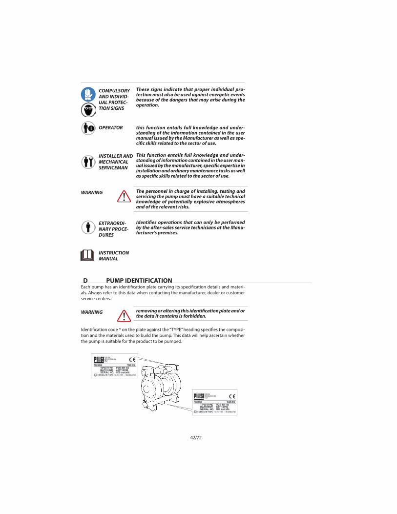
Each pump has an identi!cation plate carrying its speci!cation details and materi-
als. Always refer to this data when contacting the manufacturer, dealer or customer
service centers.
Identi!cation code * on the plate against the “TYPE” heading speci!es the composi-
tion and the materials used to build the pump. This data will help ascertain whether
the pump is suitable for the product to be pumped.
D PUMP IDENTIFICATION
COMPULSORY AND INDIVID-UAL PROTEC-TION SIGNS
OPERATOR
INSTALLER AND MECHANICAL SERVICEMAN
EXTRAORDI-NARY PROCE-DURES
INSTRUCTION MANUAL
These signs indicate that proper individual pro-tection must also be used against energetic events because of the dangers that may arise during the operation.
The personnel in charge of installing, testing and servicing the pump must have a suitable technical knowledge of potentially explosive atmospheres and of the relevant risks.
removing or altering this identi!cation plate and or the data it contains is forbidden.
this function entails full knowledge and under-standing of the information contained in the user manual issued by the Manufacturer as well as spe-ci!c skills related to the sector of use.
This function entails full knowledge and under-standing of information contained in the user man-ual issued by the manufacturer, speci!c expertise in installation and ordinary maintenance tasks as well as speci!c skills related to the sector of use.
Identi!es operations that can only be performed by the after-sales service technicians at the Manu-facturer’s premises.
WARNING
WARNING

43/72
EN
In compliance with the 94/9/CEE standards, the pumps carry the following identi-
!cation marks:
II 3/3 GD c IIB T135°C
: safety symbol to Din 40012 attachment A.
II 3/3GD: surface equipment used in areas where the presence of gas, vapors or mists
in addition to clouds of combustible powder in the air is unlikely during normal op-
eration both in external and internal areas and, if it does occur, it will only persist for
a short period (ZONE 2).
c: protection by constructional safety (EN 13463-5).
IIB: Excluding the following products: hydrogen, acetylene, carbon disulphide.
T135°C: Class of admitted temperatures. The processed $uid temperature value
must fall within such class range and the user must comply with the instructions
contained in the manual and with the current laws. Furthermore, the user must take
into account the ignition point of the gases, vapors and mists in addition to clouds
of combustible powder in the air existing in the area of use.
MARKINGS AND GENERAL INFORMATION
IDENTIFICATION CODE
D1
E
CODE PUMPPump casing
Diaphragmair side
Diaphragm!uid side
Balls Balls seats O-RINGS
F00208P00 PIUSI MP 130 PP HYTREL PTFE PTFE PP PTFE
F00208A00 PIUSI MA 130 ALU NBR NBR NBR ALU NBR
F00208P20 Piusi MP 140 PP HYTREL PTFE PTFE PP PTFE
F00208P10 Piusi MA 140 PP NBR NBR NBR PP NBR
F00208P30 Piusi MP 180 PP HYTREL PTFE PTFE PP PTFE
F00208A10 Piusi MA 180 ALU NBR NBR NBR PPS-V NBR
F00208P40 Piusi MP 190 PP HYTREL PTFE PTFE PP PTFE
F00208A20 PIUSI MA 190 ALU NBR NBR NBR PPS-V NBR

44/72
Proposed use
Functioning principles
F PUMP DESCRIPTIONThe air-driven Piusi Ma and Piusi MP pumps have been designed and constructed to pump liquids with an apparent viscosity of between 1 and 50.000 cps at 20°C that are chemically compat-ible with the pump’s components. Fluid service temperatures must range from +3°C to a maximum of 65/95°C according to the material of the components. Its use is de!ned by the type of material used to build the pump, the temperature class and the type of $uid. The maximum temperature allowed for process $uid or powder depends on and/or is declassed by the material of the pump; if exceeded, respect of the maximum temperature shown on the marking cannot be guaranteed.
TEMPERATURE CLASSES FOR PUMPS TO BE INSTALLED IN AN EXPLOSIVE ENVIRONMENT
DEFINITION OF THE CALCULATION DATA:
T4 = ATEX temperature class 135°CTa = maximum ambient temperature 40°C;Tl = maximum temperature for dry use of the pump in the work-place (50°C);Δs = safety factor (5°C);Tf = maximum allowed $uid processing temperature
In particular, it is FORBIDDEN to use Piusi MA and Piusi MP pumps for : - production of vacuum;- operation as an on-o" valve, as a non-return valve or as a metering valve- operation with liquid that is chemically incompatible, with the materials of construction;- operation with suspended products whose speci!c weight is higher than the liquid’s (for example with water and sand);- with air pressures, temperatures or product characteristics that do not comply with the pump’s technical data;
The air introduced behind the diaphragm pushes the product to the delivery side. At the same time, it uses the shaft to draw the opposite diaphragm, which causes suction at the intake side. When complete, the cycle reverses.
Improper use:
use of a Piusi MA and Piusi MP pumps for any other use other than that previously described in the chapter entitled “TECHNICAL CHARACTERISTICS” is to be considered improper use of the pump and is therefore forbidden by Piusi.
since an endless variety of products and chemical compositions exist, the user is presumed to have the best knowledge of their reaction and compatibility with the pump’s construction materials. Therefore, before using the pump, all necessary checks and tests must be performed with great care to avoid even the slightest risk, an event that the manufac-turer cannot foresee and for which he cannot be held responsible.
WARNING
WARNING

45/72
EN
the user must consider the ratio between the pump’s maximum surface temperature indicated on the marking and the minimum ignition temperature of the layers and clouds of powder as shown in the EN1227-1.
Use of the pump that does not comply with the instructions indicated in the use and maintenance manual will cancel the safety and explosion protec-tion requirements. The risks associated with use of the pumps under the exact conditions set forth in the use and maintenance manual have been analysed, whilst the analysis of the risks associated with the interface with other system components must be carried out by the installer.
the declared capacity of dry negative suction refers to the intake of "uids with a viscosity and speci!c weight equal to 1; the performance and duration of the pump’s membrane depend on the following factors:- the "uid’s viscosity and speci!c weight;- the length and diameter of the suction pipe.
NEGATIVE SUCTION: with "uids max. up to 5,000 cps at 18° C
BELOW HEAD SUCTION: with "uids up to 50,000 cps at 18° C
ATEX: The user is responsible for classifying the area of use whilst identi!cation of the equipment category is the responsibility of the manufacturer.
WARNING
WARNING
WARNING
WARNING
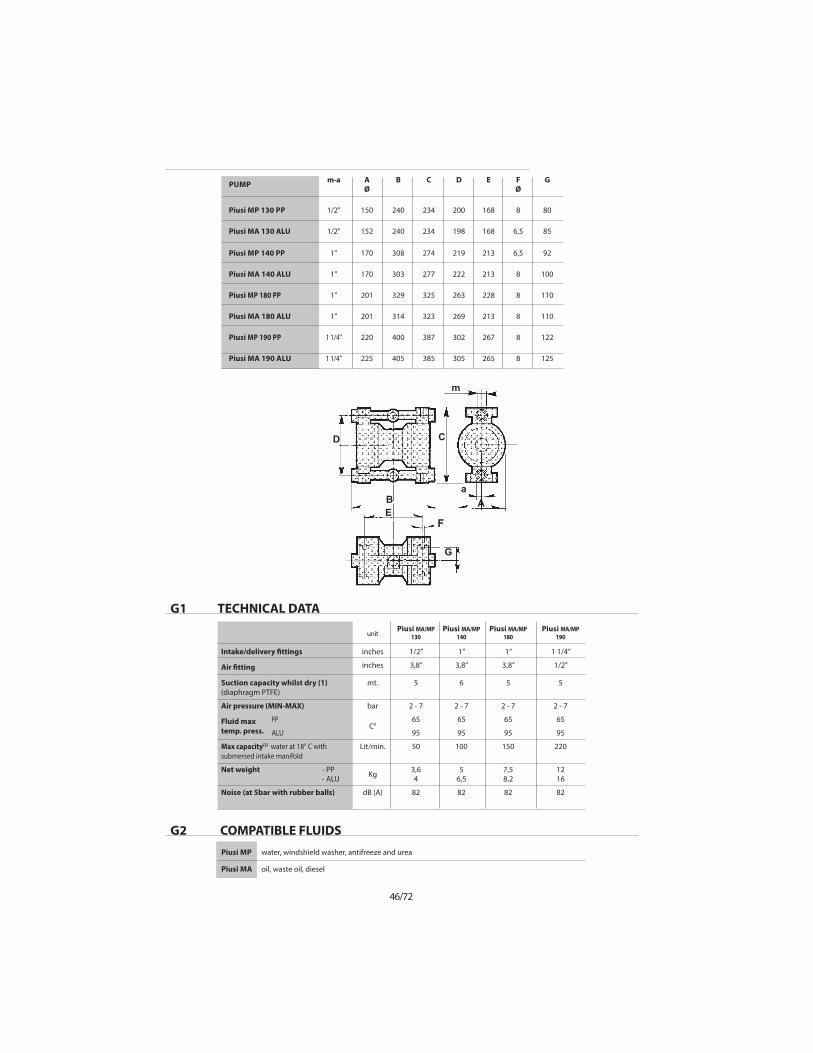
G TECHNICAL FEATURESThe performances data refers to standard versions. “MAX delivery” and “Suction ca-pacity” values refer to the pumping of water at 18°C with a submersed manifold (please see !g. 1). (1) (2)
"g. 1
46/72
G1
G2
TECHNICAL DATA
COMPATIBLE FLUIDS
PUMPm-a A
ØB C D E F
ØG
Piusi MP 130 PP 1/2” 150 240 234 200 168 8 80
Piusi MA 130 ALU 1/2” 152 240 234 198 168 6,5 85
Piusi MP 140 PP 1” 170 308 274 219 213 6,5 92
Piusi MA 140 ALU 1” 170 303 277 222 213 8 100
Piusi MP 180 PP 1” 201 329 325 263 228 8 110
Piusi MA 180 ALU 1” 201 314 323 269 213 8 110
Piusi MP 190 PP 1 1/4” 220 400 387 302 267 8 122
Piusi MA 190 ALU 1 1/4” 225 405 385 305 265 8 125
AB
CD
EF
G
m
a
unitPiusi MA/MP
130
Piusi MA/MP
140
Piusi MA/MP
180
Piusi MA/MP
190
Intake/delivery "ttings inches 1/2” 1” 1” 1 1/4”
Air "tting inches 3,8” 3,8” 3,8” 1/2”
Suction capacity whilst dry (1)
(diaphragm PTFE)
mt. 5 6 5 5
Air pressure (MIN-MAX) bar 2 - 7 2 - 7 2 - 7 2 - 7
Fluid max
temp. press.
PPC°
65 65 65 65
ALU 95 95 95 95
Max capacity(2) water at 18° C with
submersed intake manifold
Lit/min. 50 100 150 220
Net weight - PP- ALU
Kg3,64
56,5
7,58,2
1216
Noise (at 5bar with rubber balls) dB (A) 82 82 82 82
Piusi MP
Piusi MA
water, windshield washer, antifreeze and urea
oil, waste oil, diesel

47/72
EN
H
I
WARRANTY
SAFETY RULES
The high quality of Piusi MA and Piusi MP pumps is often con!rmed to us by the
end users.
However, should any defect appear, please contact the Manufacturer’s After-Sales
Service, your dealer or the nearest Customer Service Centre twhere you will receive
assistance as quickly as possible. In any case, please provide:
A. Your complete address
B. Pump identi"cation
C. Explosion risk protection class
D. Anomaly description
All Piusi MA and Piusi MP pumps are covered by the following warranty:
1. Twelve months for any faulty mechanical parts. The warranty period starts from
the date of supply.
2. Any fault or anomaly must be reported to the Manufacturer within eight days.
3. Warranty repair will be carried out exclusively at the Manufacturer’s premises.
Transportation charges will be at the client’s expense.
4. Warranty shall not be extended in case of repair or replacement.
5. Faulty parts must be forwarded to the Manufacturer who
reserves the right to test them in this own factory to identify the fault or any external
reason that may have caused it. Should the parts be found not faulty, the Manufac-
turer reserves the right to invoice the total cost of the parts that had been replaced
under this warranty.
Costs and transportation risks of faulty, repaired or replaced parts including custom
charges will be borne entirely by the client.
Repair or replacement of faulty parts cover any obligation under this warranty.
The warranty DOES NOT cover any indirect damage and in particular any normal
consumable material such as diaphragms, ball seats, and others.
The warranty does not cover parts damaged as a consequence of incorrect installa-
tion, carelessness, neglect, incorrect maintenance, or damages due to transporta-
tion or to any other reason or event that is not directly linked to functional or man-
ufacturing defects.
The warranty excludes all cases of improper use of the pump or incorrect appli-
cations or non-observance of the information contained in this manual.
these instructions are essential for the pumps’ compliance to the requirements of the 94/9/CE directive and must therefore be available, known, understood and applied.
the personnel in charge of installing, inspecting and servicing the pumps must have suitable technical knowledge and training in matters con-cerning potentially explosive atmospheres and the related risks.
WARNING
WARNING
Dangerous or hazardous practices or practice not complying with the safety rules
and with the recommendations contained herein, may cause serious injuries, mate-
rial damage and even explosions and /or death for which the manufacturer cannot
be held responsible.

48/72
use of the pumps in a manner that does not comply with the instructions indicated in the use and main-tenance manual will cancel all the requirements for safety and protection against of explosions.
the maximum allowed temperature for process "uids or powder is equal to 65/95°C depending on the construction materials; if exceeded, respect of the maximum temperature marked on the machine cannot be guaranteed.
before using the pump, make sure that the "uid to be pumped is compatible with the explosion protection class and with construction materials of the pump: danger of corrosion,product spills and/or explosions caused by chemical reactions.
before intervening on the pump and/or servicing or repairing it, please note that you must:
A. Discharge any product that was being pumpedB. Wash it internally using a suitable non-"ammable "uid, then drain.C. Cut-o$ the air supply using the relevant valve and make sure that no residual pressure remains inside it. D. Close all on-o$ valves (delivery and intake sides) relative to the product;E. Disconnect the network air supply;F. Wear suitable individual protection before any mainte-nance or repair (goggles/face protection, gloves, closed shoes, aprons and others).
WARNING
WARNING
WARNING
WARNING
For installation and use in a potentially explosive environment, comply with these
general precautions:
- ascertain that the pump is full and if possible, that the level is above it by 0.5 m;
- ascertain that the $uid treated does not contain or cannot contain large solids or
solids of a dangerous shape;
- ensure thet the intake or delivery ports are not obstructed nor limited to avoid
cavitation or pneumatic motor strain;
- also ascertain that the connection piping is strong enough and cannot be de-
formed by the pump weight or by the intake. Also check that the pump is not bur-
dened by the weight of the piping.
- If the pump is to stay in disuse for a long period of time, clean it carefully by running
a non-$ammable liquid detergent through it that is compatible with the pump’s
construction materials;
- if the pump was turned o" for a long period of time, circulate clean water it in for
some minutes to avoid incrustations.
- before starting, after long periods of disuse, clean the internal and external surfac-
es with a damp cloth;
- check the grounding;
- always protect the pump against possible collisions caused by moving objects or
by various blunt materials that may damage it or react with its materials;
- protect the pump’s surrounding ambient from splashes caused by accidental
pump failure;
- if the diaphragms are completely torn, the $uid may enter the air circuit, damaging
it, and be discharged from the exhaust port. It is therefore necessary for the exhaust
port to be conveyed by pipes to a safe area.

49/72
EN
the air supply pressure must never be over 7 bar or below 2 bar.
when using the pump with aggressive or toxic liq-uids or with liquids that may represent a health haz-ard you must install suitable protection on the pump to contain, collect and signal any spills: danger of pollution, contamination, injuries and/or death.
installing the pumps without on-o$ valves on the intake and delivery sides to intercept the product in case of spillage is forbidden: danger of uncontrolled product spillage.
installing the pumps without on-o$, three-way or check valves on the air supply piping to prevent the pumped liquid from entering the pneumatic circuit if the diaphragms are broken is forbidden: danger of "uid entering the compressed air circuit and being discharged into the environment.
should the user think that the temperature limits set forth in this manual may be exceeded during service, a protective device must be installed on the system to prevent the maximum allowed process temperature from being reached. If exceeded, re-spect of the maximum temperature marked cannot be guaranteed.
the pumps must always be grounded irrespective of any organ to which they are connected. Lack of grounding or incorrect grounding will cancel the requirements for safety and protection against the risk of explosion.
the use of pumps made with non-conductive material, which become charged with static, and without suitable grounding for "ammable liquids is forbidden: risk of explosions due to static charge.
aggressive, toxic or dangerous liquids may cause serious injuries or damage to health, therefore it is forbi$en to return a pump containing such products to the manufacturer or to a service center. You must empty the internal circuits from the product !rst and wash and treat it.
pumps containing aluminium parts or components coming into contact with the product cannot be used to pump III-trichloroethane, methylene chloride or solvents based on other halogenated hydrocarbons: danger of an explosion caused by a chemical reaction.
the pump must not be used with "uids that are not compatible with its construction materials or in a place containing incompatible "uids.
WARNING
WARNING
WARNING
WARNING
WARNING
WARNING
WARNING
WARNING
WARNING
WARNING

50/72
The components of the pneumatic exchanger, including the shaft are made from materials that are not speci!cally resistant to chemical products. If the diaphragm should break, replace these ele-ments completely if they have come into contact with the product.
the diaphragms (in contact with the product or the external ones) are highly subject to wear. Their duration is strongly a$ected by the conditions of use and by chemical and physical stress. Fields tests carried out on thousands of pumps with a head val-ue from 0° to 18° C have shown that normal service life exceeds one hundred million cycles. However, in places at risk of explosion, the diaphragm must be disassembled and checked every 5 million cycles and replaced every 20 million cycles.
The air-driven motor of the Piusi MA and Piusi MP pumps is self-lubricating and will not require any greasing. Therefore avoid using lubricated and non-dried air.
periodic controls must be made to ensure that there is no powder and/or deposits on the external and internal surfaces of the pump and, if necessary, they must be cleaned with a damp cloth.
removal of the silencer and the air supply !tting must be done when free from powder. Before restarting the pump, ensure that no powder has entered the pneumatic distributor.
ascertain that during service no anomalous noise appears. In that case, stop the pump immediately.
contain gas. Therwise stop the pump immediately.
WARNING
WARNING
WARNING
WARNING
WARNING
WARNING
WARNING
To replace worn parts, use only original spare parts.
Failure to comply with the above may give rise to risks for the operator, the
technicians, the persons, the pump and/or the environment that cannot be as-
cribed to the manufacturer.
L TRANSPORT AND POSITIONING
The operators in charge of the assembly / disassembly must be informed and trained
on the dangers relating to the use of mechanical tools, even small ones.
The noise levels of the machine correspond to:
• The sound pressure level of the A weighted emission, in the working place, is less
than 78 dB.
Upon receipt, please check that the packing and the pump are intact and have not
been damaged. Then:
1. Depending on the size and weight, the material is forwarded packed in cardboard
cases on a pallet or in a crate: on receipt open and remove the packing.
2. Read the User and Maintenance Manual and proceed as explained.

51/72
EN
3. Make sure that all of the pump’s screws are well tightened.
4. Hoist the pump using suitable equipment according to the weight shown on the
plate.
5. If the pump has been forwarded with drain silencer disassembled, mount the
same.
6. Position the pump correctly on the site chosen for installation, as close as possible
to the point of collection and secure onto the feet using the bolts supplied. Arrange
for enough room to carry out maintenance.
1 2
3
4
5
Position and secure the pump horizontally using hangers !xed to the ceiling or feet resting on the ground. The product delivery manifold must al-ways be positioned on the upper part according to the signs: “OUT” = DELIVERY (up)“IN” = INTAKE (down) or according to the pump model, check that the arrows shown onto the casing are always poin-ting upwards.
diaphragm pumps with negative suction are a$ect-ed by the following factors:- viscosity and speci!c weight of the "uid;- suction diameter and length.Position the pump as close as possible to the point of collection (within 2,5 m.) and in any case never more than 5 m.
WARNING
WARNING

52/72
7. If the pump is made from conductive materials and is suitable for $ammable prod-
ucts, each pump casing must be equip-ped with a suitable earthing cable: DANGER
OF EXPLOSION AND/OR FIRE.
This completes positioning.
The diameter of the intake pipe must never be smaller than the connection of the pump, but must be increased as the distance increases. Fluid to be pumped with negative suction must never exceed a viscosity of 5,000 cps at 20° C and a speci!c weight of 1.4 Kg/l. These elements can cause derating and reduce the duration of the diaphragm: DANGER OF PREMATURE BREAKAGE.
The pumps must always be grounded irrespective of any organ to which it is connected. Lack of grounding or incorrect grounding will cancel the requirements for safety and protection against the risk of explosion.
WARNING
WARNING
!
OK
OUT
IN
6

53/72
EN
M CONNECTING THE PRODUCT CIRCUITAfter positioning the pump you can now connect it to the product circuit as follows:
1. On the delivery and discharge manifold install a manual valve of the same diam-
eter as the pump inlet (never smaller) to intercept the $uid correctly in case of spills
and/or when servicing the pump.
2. Install the sleeves to secure the $exible hoses on both valves.
3. In the event of a vertical delivery higher than 5 meters, we advise to use a check
valve to prevent the $uid from returning into the pump.
only !ttings with cylindrical gas threads in materials compatible with both the "uid to be pumped and the pump’s construction materials must be used. For example: Pump made from PP = PP !tting
the pump must be connected with FLEXIBLE HOSES REINFORCED WITH A RIGID SPIRAL of a diameter never smaller than the pump’s connection. The !lters or other equipment installed at the intake side must be suitably dimensioned in order to avoid pressure drops. For negative installations and/or viscous "uids, use hoses with an OVERSIZE DIAME-TER, especially on the intake side. Do not attach the pump DIRECTLY with rigid metal pipes (on plastic pumps) and/or pipes with tapered thread, as they can cause severe stress and/or vi-brations and breakage of the manifolds and other parts of the pump.Always use flexible joints with fittings made of the same material of the pump (PP with PP, ALU with ALU)Do not use threadlockers and/or Te"on paste. The installer must ensure that the !ttings are centred during assembly to prevent cracks and/or to prevent the threads from yielding.Also check that any excess PTFE tape and excessive clamping pressure does not place stress on the manifold or other parts of the pump.Pay particular attention to stress corrosion crack-ing. The pump material may deteriorate due to the combined action of corrosion and application of a load, which may cause parts subjected to stress to break suddenly and unexpectedly, especially at low temperatures.Check if the connection tubes to the pump are clean inside and do no contain any working residue.
WARNING
WARNING
1 2

54/72
4. Connect the product intake and delivery hoses to their respective !ttings whilst
taking into consideration the signs on the pump:
“IN” = INTAKE (down) and
“OUT” = DELIVERY (up)
or according to that indicated by the arrows.
5. Secure the hoses using the relevant clamps.
6. If used for drum suction (not below head), the submersed end of the intake hose
must be provided with a diagonally cut !xing to prevent it from adhering to the
drum bottom.
Connection of the product circuit "nishes here.
Provide appropriate support for the piping. THE PIPING MUST BE STRONG ENOUGH TO AVOID DEFORMATION DURING THE SUCTION PHASE AND MUST NEVER WEIGH DOWN ON THE PUMP IN ANY WAY OR VICE VERSA.
WARNING
Ascertain that the "uid treated does not contain or cannot contain large solids or solids of a dangerous shape and that the intake or delivery ports are not obstructed nor limited to avoid either cavitation or pneumatic motor strain.
WARNING
4
5
OK

55/72
EN
pneumatic supply to the Piusi MA and Piusi MP pumps must be made using FILTERED, DRIED, NON LUBRICATED OIL FREE AIR at a pressure of not less than 2 bars and not more than 7 bars.
do not remove RESET for any reason and/or do not con-nect the air supply to the RESET channel.
to measure the actual air pressure, install a pressure gauge on the air connection of the pump and check the value while the pump is running.
WARNING
WARNING
REMARK
N PNEUMATIC CONNECTIONTo connect the pump to the pneumatic circuit, you must:
1. Remove the adhesive sticker from the air connection.
2. Install an on-o" valve, a three-way valve and a check valve on the pneumatic cir-
cuit connection on board the pump according to the layout shown in !gure 1.
ONLY FILTER NO OIL
E CONNE T TERE L’ AR IA
RIM
UO
VERE QUESTA E T ICHE T TA

56/72
to avoid in pressure drops, use hoses, accessories and control and regulation elements whose deliv-ery and pressure characteristics are suitable to the pump’s own characteristics.
most snap-on !ttings cause pressure drops.
WARNING
WARNING
3. Connect the supply hose from the net work to the pump circuit.
4. Adjust the network pressure of the compressed air to guarantee a pressure of
NOT LESS THAN 2 bars AND NOT MORE THAN 7 bars when the pump is running. For
Piusi MA and Piusi MP pumps equipped WITH RUBBER BALLS, DO NOT EXCEED 5
bars. Lower or higher pressure may cause functional problems or pump breakage,
product spills and damages to persons or objects.
5. In the event that the pump stalls, whatever may have caused the stall must be
eliminated (see page 66), after which reset by rotating the manual device by half a
turn in an anti-clockwise direction. Wait for the pump to re-start and re-screw the
reset device.
6. If the number of pump cycles needs to be recorded or displayed, install the
STROKE COUNTER.
7. Always protect the pump from possible accidental collisions with moving objects
or various blunt materials that may damage it or react on contact with it.
8. Protect the site and the persons from accidental failures by installing a protection
guard to hold and collect any product leakage: DANGER OF SERIOUS INJURIES AND
DAMAGE TO HEALTH AND/OR OBJECTS.
9. If the diaphragms are completely torn, the $uid may enter the air circuit, damag-
ing it, and be discharged through the exhaust port. It is therefore necessary that the
air exhaust be conveyed by pipes to a safe area.
to feed more than one pump with the same air control device, please ask our engineers.
REMARK
min 2 bar
max 7 bar
NO OIL

57/72
EN
6
7
O COMMISSIONINGThe user must always use materials that are compatible with the pumped liquid according to the pump’s design conditions.
To commission the pump, proceed as follows:
1. Make sure that the product delivery and intake hoses are correctly connected - check the signs on the pump: “IN” = INTAKE (down) and“OUT” = DELIVERY (up)
2. Check that the pump’s pneumatic circuit valves are correctly installed (on-o" ball valve, three-way valve and check valve).
3. Open the $uid intake and delivery valves.
it is forbidden to use the pump with "uids that are not compatible with the pump’s construction mate-rials or in a place that contains incompatible "uids.
WARNING
1
OUT
IN 23

58/72
4. Open the on-o" ball valve mounted on the pump connection.
5. Open the three-way valve.
6. Check and regulate the network air pressure when the pump is running: MIN 2 bar
MAX 7 bar; max 5 bar for pumps with rubber balls.
7. To regulate the speed of the pump according to the !uid viscosity, you can
operate in two ways:
A. regulate the network air pressure
B. choke the air volume ($ow rate) by means of the on-o" valve mounted on the
pump
never start the pump with the product valves (intake and delivery) closed: DANGER OF DIAPHRAGM BREAKAGE.
If the pump has negative suction, reduce the speed of the pump using the ball valve on the sir supply.
if the pressure is below 2 bars when the pump is run-ning, the pump may STALL. At a pressure higher than the MAXIMUM threshold, yielding and leakages of the product under pressure may occur and/or the pump may break.
WARNING
WARNING
CAUTION
5
min 2 bar
max 7 bar
4 6
unprimed pumps have a negative suction head capacity that varies according to the type of dia-phragm and packing mounted. PLEASE CONTACT THE MANUFACTURER’S CUSTOMER ASSISTANCE SERVICE FOR FURTHER DETAILS.
REMARK
7A 7B

59/72
EN
In pumps with split manifold, DO NOT USE TWO FLUIDS WITH DIFFERENT VISCOSITIES as STALL, PREMATURE DIAPHRAGM AND PNEUMATIC CIRCUIT WEAR may occur.
WARNING
8. Only the air supply must be used to stop the pump, by closing the three-way valve
to discharge any residual pressure from the pump’s pneumatic circuit.
After two hours of operation, and after stopping the pump correctly, check that all
of the bolts are tight.
Besides being damaging for the pump, cavitation is dangerous in a potentially ex-
plosive atmophere: You must ascertain that the pump has been sized correctly. In
case of doubt, please contact PIUSI.
never stop the pump when it is running and/or when the pneumatic circuit is under pressure by closing the intake and/or delivery valves on the "uid circuit: DANGER OF PUMP STALLING AND PREMATURE WEAR AND/OR BREAKAGE OF THE DIAPHRAGM.
ascertain that no anomalous noises occur during operation. If so, stop the pump immediately.
In the case of high viscosity "uids, do not use un-der-sized !lters or piping, especially on the intake side. Furthermore, you must decrease the pump speed by choking the volume of air whilst leaving pressure unchanged.
ascertain that the "uid at the delivery side does not contain gas. Otherwise stop the pump immediately.
WARNING
WARNING
WARNING
WARNING
9

60/72
General
Danger Sign
Danger
Corrosive
Material
Danger
Flammable
Material
Danger
Explosive
Material
Danger Toxic
Material
Danger
Incandes-
cent Liquid
Sprinkles
Prohibition
on Open
Flames’ Use
No smoking
Put the following prohibition and danger signs near the place where the pump is
installed
P PRODUCT CIRCUIT MAINTENANCE
A. discharge the product being pumped and close the product on-o" valves (both on the intake and delivery sides).
B. Circulate a suitable non-$ammable washing $uid then drain it o" and close the product shut-o" valve.
C. Shut-o" the air supply using the relevant three-way valve whilst making sure that no residual pressure subsists.
D. Shut-o" air supply upstream;
E. Wait for the pump to cool down for at least !fteen minutes;
F. Perform the necessary operations while wearing protection gloves and any other appropriate personal protection equipment (face masks, gloves, closed shoes, etc.): DANGER OF BURNING AND EJECTION OF LIQUID UNDER PRESSURE.
before intervening on the pump and/or performing any maintenance or repair, you must:
WARNING
CA

61/72
EN
÷ 0 bar
D E
remove deposits of powder from the external sur-faces of the pump with a cloth soaked in suitable neutral detergents.
before carrying out this operation all external surfaces of the pump must be cleaned using a damp cloth.
WARNING
WARNING
1. Disconnect $uid intake and delivery hoses from pump.
2. Disconnect the compressed air supply pipe from the pump.
3. Disassemble and remove the pump from its place of installation using suitable hoisting equipment.
4. Periodically control and clean the internal surfaces with a damp cloth.
To clean and/or replace the balls and ball seats, proceed as follows:
A1. disassemble the intake and delivery manifolds by removing the !xing elements.
A2. Remove the seats and the balls and clean them with a damp cloth and/or replace them with genuine spare parts of the same type.
A3. Check the condition of the gasket and, if necessary, replace with original spare parts of the same type.
P1 CLEANING AND REPLACING THE BALLS AND BALLS SEATS
A1

62/72
the diaphragms (in contact with the product or the external ones) are highly subject to wear. Their duration is strongly a$ected by the conditions of use and by chemical and physical stress. Fields tests carried out on thousands of pumps installed with a head equal to 0 and with "uid at 18° C have shown that normal service like exceeds 100,000,000 (one hundred million) cycles. For safety reasons, in environments at risk of explosion, the diaphragms must be replaced every 20,000,000 (twenty million) cycles.
the components of the pneumatic exchanger, including the shaft, are made from materials that are not speci!cally resistant to chemicals. Should the diaphragms break and the components come into contact with the "uid, replace them completely.
WARNING
WARNING
For good operation of the pump and to guarantee that all the safety and protection requirements against explosion risks have been taken, it is indispensable that the controls, cleaning and/or replacement of the diaphragms are carried out in accordance with the intervals shown in the table.
To replace product diaphragms proceed as follows:
B1. Disassemble the intake and delivery manifolds by removing the !xing elements.
P2 CLEANING AND REPLACING THE DIAPHRAGMS
A2 A3
check that there are no deposits of any kind inside the pump, and if found remove them with a damp cloth.
CAUTION
A4. Reassemble by repeating the previous sequence in reverse order. Tighten the !xing bolts evenly.
Cleaning and/or replacement of balls and ball seats "nishes here. You can now reposition the pump and reconnect it as described in the previous sections.
A4
OBLIGATORY
OPERATION
OPERATION TIME (nr. of cycles)
every 500.000 every 5 milion after 20
milion
CONTROL AND
INTERNAL CLEANING
•
DIAPHRAGM
CHECK
_ • _
DIAPHRAGM
REPLACEMENT
_ _ •

63/72
EN
periodic controls must be made to ensure that there are no deposits of powder on the internal surfaces and, if necessary, they must be cleaned with a damp cloth.
Should the pump be returned to the manufacturer or to a service center, you must !rst empty it out com-pletely. If toxic, noxious or other types of dangerous products have been used, the pump must be suitably treated and washed before it is sent.
before intervening on the pump and/or performing any maintenance or repair, you must:
WARNING
WARNING
WARNING
B2. Remove any deposits on the internal surfaces with a damp cloth.
B3. Disassemble the two pump casings by removing the !xing screws.
B4. Remove the external diaphragm locking cap from both circuits.
B5. Check and/or replace the diaphragms on both sides of the pump with original spare parts of the same type.
B6. Reassemble the pump following the disassembly sequence described earlier in reverse order. Tighten the !xing bolts evenly.
Replacing the diaphragms "nishes here. You can now reposition the pump and reconnect it as described in the previous sections.
ascertain that the inner part of the pump is free from all types of deposits,and if they are present proceed with their removal.
CAUTION
A. discharge the product being pumped and close the product on-o" valves (both on the intake and delivery sides).
B. Circulate a suitable non-$ammable washing $uid then drain it o" and close the product shut-o" valve.
C. Shut-o" the air supply using the relevant three-way valve whilst making sure that no residual pressure subsists.
D. Shut-o" air supply upstream;
E. Wear suitable individual protective devices before intervening: goggles/masks, gloves, closed shoes, aprons, and others): DANGER OF FLUID EJECTION UNDER PRESSURE.
Q AIR CIRCUIT MAINTENANCE
B6B5

64/72
before removing the air supply pipe or !tting, clean the external surfaces of the pump. Before restarting the pump, ensure that no powder has entered the pneumatic distributor.
WARNING
CA
÷ 0 bar
D E
1. Disconnect $uid intake and delivery hoses from pump.
2. Disconnect the compressed air supply pipe from the pump.
3. Disassemble and remove the pump from its place of installation using suitable hoisting equipment.
All Piusi MA and Piusi MP pumps have a coaxial pneumatic exchanger; to replace it proceed as follows:
1
2
3
Should the pump be returned to the manufacturer or to a service center, you must empty it out com-pletely. If toxic, noxious or other types of dangerous products have been used, the pump must be suitably treated and washed before it is sent.
WARNING
Q1 REPLACING THE COAXIAL PNEUMATIC EXCHANGER

65/72
EN
B1. Disassemble the intake and delivery manifolds by removing their !xing elements.
B2. Disassemble the two pump casings by removing the relevant !xing screws.
B3. Remove the external diaphragm locking cap from both the circuits.
B4. Remove the diaphragms from both sides of the pump.
B5. Disassemble the pneumatic exchanger by removing the relevant !xing elements.
B6. Replace the exchanger and the connection shaft with original spare parts having the same characteristics.
B6.1 For pumps with manual reset on the main casing, the air exchanger must be placed so that the reference bevel is turned towards the resetting duct.
B7. Reassemble the pump according to the previously described sequence but in reverse order and tighten the !xing bolts evenly.
Replacement of the coaxial pneumatic exchanger "nishes here. You can now reposition the pump and reconnect it as described in the previous sections.
B1 B2 B3 B4
to avoid incorrect reassembly and subseguent malfunction of the pump the coaxial pneumatic exchangers must not be open.
WARNING
B5B6
B6.1 B7
66/72
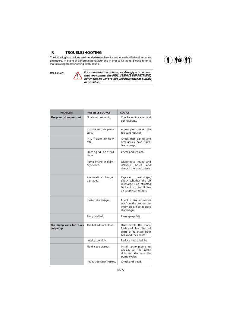
R TROUBLESHOOTING
The pump does not start
The pump runs but does not pump
POSSIBLE SOURCEPROBLEM ADVICE
No air in the circuit.
Insufficient air pres-sure.
Insufficient air flow rate.
D a m a g e d c o n t r o l valve.
Pump intake or deliv-ery closed.
Pneumatic exchanger damaged.
Broken diaphragm.
Pump stalled.
The balls do not close.
Intake too high.
Intake side is obstructed.
Fluid is too viscous.
Check circuit, valves and connections.
Adjust pressure on the relevant reducer.
Check that piping and accessories have suita-ble passage.
Check and replace.
Disconnect intake and delivery hoses and check if the pump starts.
Replace exchanger; check whether the air discharge is ob- structed by ice. If so, clear it. See air supply paragraph.
Check if any air comes out from the product de-livery pipe. If so, replace diaphragm.
Reset (page 56).
Disassemble the mani-folds and clean the ball seats or re place both balls and their seats.
Reduce intake height.
Check and clean.
Install larger piping es-pecially on the intake side and decrease the pump cycles.
The following instructions are intended excluvively for authorised skilled maintenance
the following trobleshooting instructions.
For more serious problems, we strongly oraccomend that you contact the PIUSI SERVICE DEPARTMENT; our engineers will provide you assistance as quickly as possible.
WARNING
67/72
EN
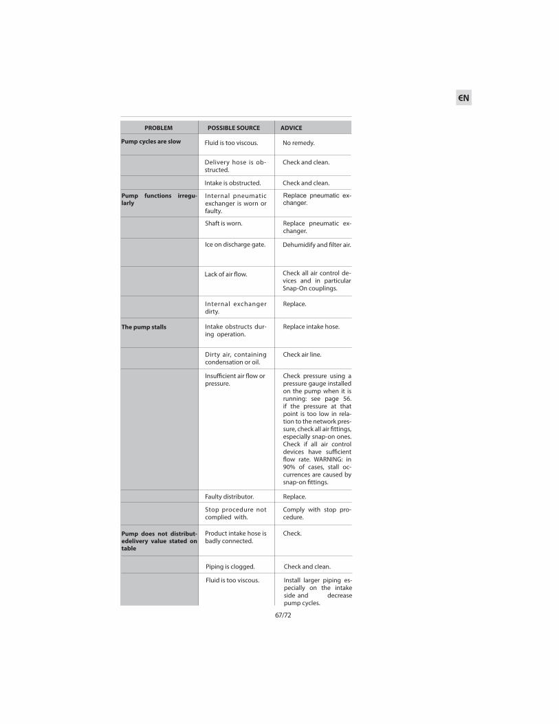
Pump functions irregu-larly
The pump stalls
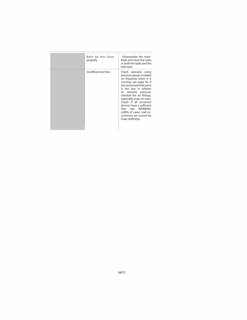
Pump does not distribut-edelivery value stated on table
POSSIBLE SOURCEPROBLEM ADVICE
Internal pneumatic exchanger is worn or faulty.
Shaft is worn.
Ice on discharge gate.
Lack of air $ow.
Internal exchanger dirty.
Intake obstructs dur-ing operation.
Product intake hose is badly connected.
Dirty air, containing condensation or oil.
Faulty distributor.
Stop procedure not complied with.
Insu&cient air $ow or pressure.
Replace pneumatic ex-changer.
Replace pneumatic ex-changer.
Dehumidify and !lter air.
Check all air control de-vices and in particular Snap-On couplings.
Replace.
Replace intake hose.
Check.
Check air line.
Replace.
Comply with stop pro-cedure.
Check pressure using a pressure gauge installed on the pump when it is running: see page 56. if the pressure at that point is too low in rela-tion to the network pres-sure, check all air !ttings, especially snap-on ones. Check if all air control devices have su&cient $ow rate. WARNING: in 90% of cases, stall oc-currences are caused by snap-on !ttings.
Pump cycles are slow Fluid is too viscous.
Delivery hose is ob-structed.
Intake is obstructed.
No remedy.
Check and clean.
Check and clean.
Piping is clogged.
Fluid is too viscous.
Check and clean.
Install larger piping es-pecially on the intake side and decrease pump cycles.
68/72
Balls do not close properly.
Insu&cient air $ow.
Disassemble the mani-folds and clean the seats or both the balls and the ball seats.
Check pressure using pressure gauge installed on thepump when it is running: see page 56. if the pressureat that point is too low in relation to network pressure, checkall the air !ttings, especially snap-on ones. Check if all aircontrol devices have a su&cient $ow rate. WARNING: in90% of cases, stall oc-currences are caused by snap-on!ttings.

69/72
EN
S DECOMISSIONINGShould the pump remain inactive for long periods, proceed as follows
1. Wash internally using products suitable for to the $uid being pumped.
2. Close the $uid intake and delivery valves mounted on the pump.3. Close the air supply using the three-way valve; this will discharge any residual pressure.
4. If you want to store the pump in the warehouse, you must respect the following:
5. If the pump was in disuse for a long period of time, circulate clean water through it for some minutes before restarting it to avoid incrustations.
Discharge any residual "uid from the pump. In case of dangerous, toxic "uids and/or otherwise noxious products, wash and treat as suitable:danger of injuries, damage to health and/or death.
Storage must be in a closed and protected environ-ment at temperatures ranging from 5 to 45°C, and a humidity level not above 90%.
WARNING
WARNING
T DEMOLITION AND DISPOSALThe Piusi MA and Piusi MP pump does not contain dangerous parts; however, when they are worn out, they must be disposed of in the following manner.
discharge any residual "uid from the pump. In case of dangerous, toxic "uids and/or otherwise noxious products, wash and treat as suitable: danger of injuries, damage to health and/or death.
WARNING
for disposal please contact specialized disposal businesses and make sure that no small or large components are dispersed in the environment which may cause pollution, accidents or direct and/or indirect damage.
WARNING
1. Disconnect pneumatic supply from pump. 2. Disassemble and remove the pump from its position.
3. Separate elements according to type (see the pump’s composition codes).

70/72

71/72
EN

PIUSI S.p.A.
Suzzara (MN) Italy