maharashtra state boarad of technical …msbte.engg-info.website/sites/default/files/summer 2016 b...
TRANSCRIPT

MAHARASHTRA STATE BOARAD OF TECHNICAL EDUCATIOD (Autonomous)
(ISO/IEC-27001-2005 Certified)
SUMMER– 2016 Examinations
Subject Code: 17329 Model Answer Page 1 of 25
Important suggestions to examiners:
1) The answers should be examined by key words and not as word-to-word as given in the model answer scheme.
2) The model answer and the answer written by candidate may vary but the examiner may try to assess the understanding level of the candidate.
3) The language errors such as grammatical, spelling errors should not be given more importance. (Not applicable for subject English and communication skills)
4) While assessing figures, examiner may give credit for principle components indicated in a figure. The figures drawn by candidate and model answer may vary. The examiner may give credit for any equivalent figure drawn.
5) Credits may be given step wise for numerical problems. In some cases, the assumed constant values may vary and there may be some difference in the candidate’s answers and model answer.
6) In case some questions credit may be given by judgment on part of examiner of relevant answer based on candidate understands.
7) For programming language papers, credit may be given to any other program based on equivalent concept.
SECTION — I
Q.1 Solve any Nine of the following: 18 Marks
a) Define the following terms related to A. C. fundamental. i) Frequency ii) RMS value. Ans: i) Frequency: ------------------------ (1 Mark)
The number of cycles completed by an alternating quantity in one second is
called as frequency.
ii) Meaning of R.M.S Value: ----------------------- (1 Mark)
The r.m.s. value of an alternating current is that steady current (d.c.) which when
flowing through a given resistance for a given time produces the same amount of heat as
produced by the alternating current when flowing through the same resistance for the same
time. OR
RMS Value = Form Factor Average Value OR
RMS Value = 0.707 maximum value
b) For delta connected load, state numerical relationship between, i) Line current and phase current ii) Line voltage and phase voltage.
Ans: Following are the : 1. The relation between line current and phase current in delta connected circuit. (1 Mark)
CurrntsphaseisIandCurrentlineisIwhereIIORII phLLphphL 33

MAHARASHTRA STATE BOARAD OF TECHNICAL EDUCATIOD (Autonomous)
(ISO/IEC-27001-2005 Certified)
SUMMER– 2016 Examinations
Subject Code: 17329 Model Answer Page 2 of 25
2. The relation between line voltage and phase voltage in delta connected circuit (1 Mark) volatgePhaseVphvoltagelineVwhereVV LLph &
c) State working principle of transformer. Ans: Working Principle of Transformer: - ------------------------------------------------- (2 Marks)
The primary winding is connected to AC supply current starts flowing through primary
winding.
The primary current produces an alternating flux in the core.
These flux gets linked with the secondary winding through the core
The alternating flux will induce voltage into the secondary winding according to the
faraday’s laws of electromagnetic induction.
OR
A Transformer works on the principle of Faradays laws of electromagnetic
induction. When their primary winding is connected to a.c. supply, a current flows
through it.
This current flowing through the primary winding produces an alternating magenetic flux .This flux links with secondary winding through the magenetic core & induces an emf in it according to the faraday’s laws of electromagnetic induction.
d) Define energy and power. State its unit.
Ans: 1. Meaning of Electric Energy: (Meaning : 1/2 Mark & Unit: 1/2 Mark)
Energy is the capacity of doing work OR Power multiplied by time is called power
tIVEnergyElectrical .. OR TimePowerElectricalEnergyElectrical The Unit of Electric Energy: KWh 2. Meaning of Electric power: (Meaning : 1/2 Mark & Unit: 1/2 Mark)
Power is defined as the rate of doing work
OR
IVPowerElectrical . The Unit of Electric Power: Watts
MAHARASHTRA STATE BOARAD OF TECHNICAL EDUCATIOD (Autonomous)
(ISO/IEC-27001-2005 Certified)
SUMMER– 2016 Examinations
Subject Code: 17329 Model Answer Page 3 of 25
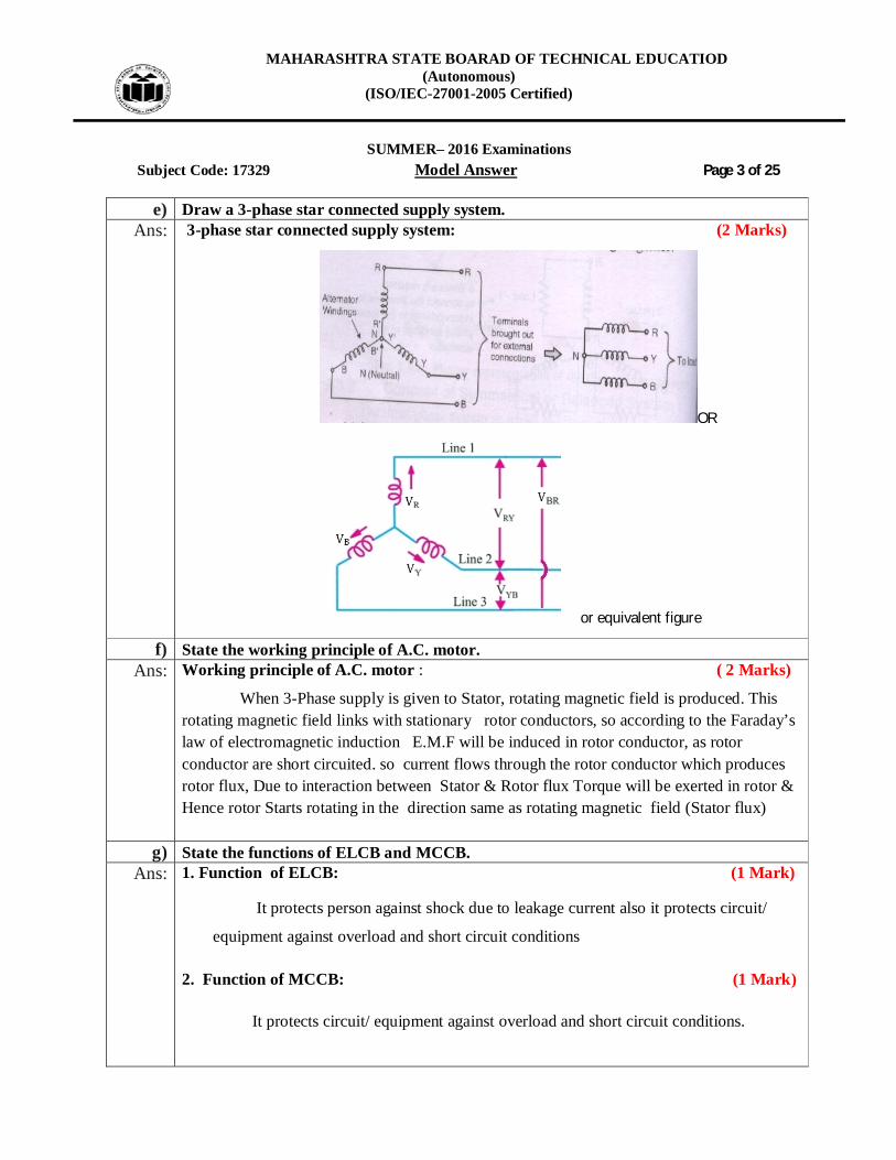
e) Draw a 3-phase star connected supply system. Ans: 3-phase star connected supply system: (2 Marks)
OR
or equivalent figure
f) State the working principle of A.C. motor. Ans: Working principle of A.C. motor : ( 2 Marks)
When 3-Phase supply is given to Stator, rotating magnetic field is produced. This rotating magnetic field links with stationary rotor conductors, so according to the Faraday’s law of electromagnetic induction E.M.F will be induced in rotor conductor, as rotor conductor are short circuited. so current flows through the rotor conductor which produces rotor flux, Due to interaction between Stator & Rotor flux Torque will be exerted in rotor & Hence rotor Starts rotating in the direction same as rotating magnetic field (Stator flux)
g) State the functions of ELCB and MCCB. Ans: 1. Function of ELCB: (1 Mark)
It protects person against shock due to leakage current also it protects circuit/
equipment against overload and short circuit conditions
2. Function of MCCB: (1 Mark)
It protects circuit/ equipment against overload and short circuit conditions.

MAHARASHTRA STATE BOARAD OF TECHNICAL EDUCATIOD (Autonomous)
(ISO/IEC-27001-2005 Certified)
SUMMER– 2016 Examinations
Subject Code: 17329 Model Answer Page 4 of 25
h) List applications of autotransformer. Ans: Autotransformer Applications- (Any Two accepted : 1 Mark each)
1. Autotransformer used as variac (to change the voltage). 2. Autotransformer can be used to start the ac machines such as induction motor. 3. Autotransformer is used to vary the supply voltage of a furnace. 4. Autotransformer can be used as a dimmerstat. 5. To give small boost to a distribution cable to correct the voltage drop. 6. Autotransformer used in control equipment for 1 phase and 3- phase electrical
locomotives. i) Name different types of safety tools.
Ans: Following are the safety tools: ( Each point: 1/2 Mark)
1. Rubber Mats: are placed in front of electrical panels and switch boards.
2. Hand Gloves: from protect shock in the working period.
3. Tester: To test the supply before working.
4. Earthing: Earth rod
OR
(Any Four Tools Expected: 1 /2Mark each, Total 2 Marks)
1. Rubber hand gloves of proper voltage rating.
2. Safety shoes
3. Safety Belt
4. Ladder
5. Earthing devices
6. Helmet
7. Line tester
8. Rope
9. Hand tools insulated
10. Dress code 100 % cotton etc.
j) State emf equation of single phase transformer. Write the meaning of each term. Ans: EMF equation of Transformer:- ( 2 Marks)
Let, N1= Number of turns in the primary
N2= Number of turns in the Secondary
MAHARASHTRA STATE BOARAD OF TECHNICAL EDUCATIOD (Autonomous)
(ISO/IEC-27001-2005 Certified)
SUMMER– 2016 Examinations
Subject Code: 17329 Model Answer Page 5 of 25
m= Maximum flux in core (wb)= BmxA
F= Frequency
E1 = 4.44 f 1mN
E1 = 4.44 f BmAN1
Secondary winding:
E2 = 4.44 f 2mN
E2 = 4.44 f Bm A N2
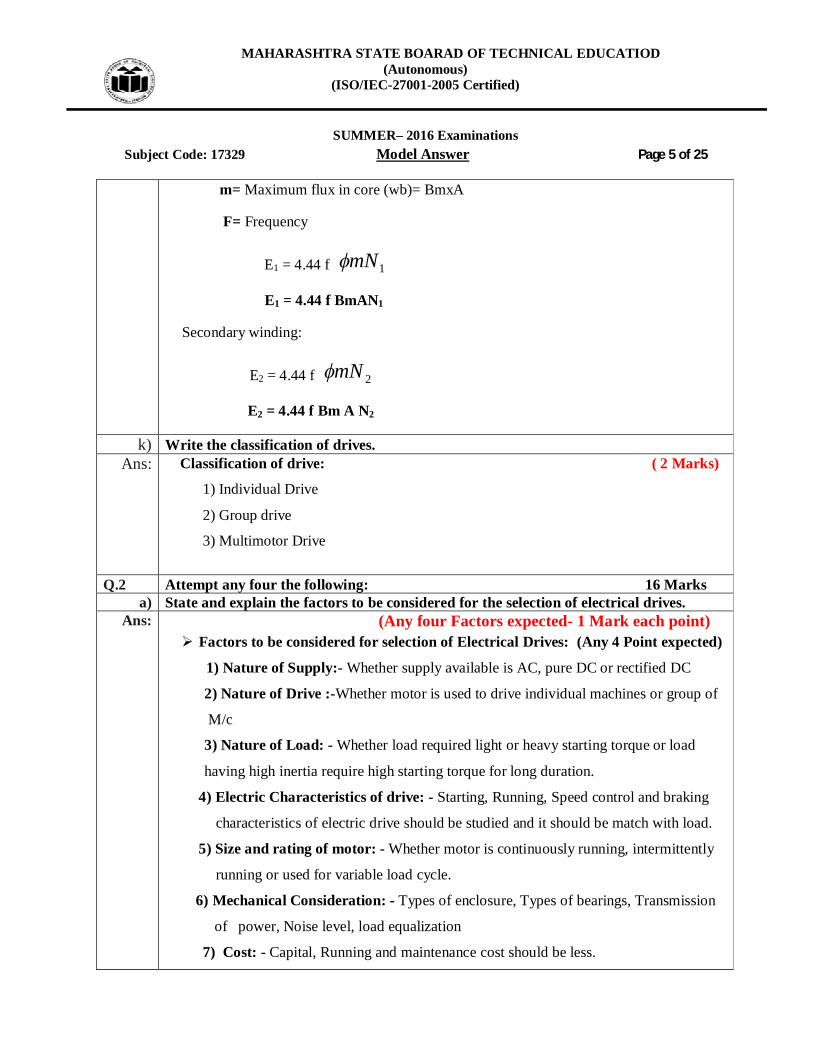
k) Write the classification of drives. Ans: Classification of drive: ( 2 Marks)
1) Individual Drive
2) Group drive
3) Multimotor Drive
Q.2 Attempt any four the following: 16 Marks
a) State and explain the factors to be considered for the selection of electrical drives. Ans: (Any four Factors expected- 1 Mark each point)
Factors to be considered for selection of Electrical Drives: (Any 4 Point expected)
1) Nature of Supply:- Whether supply available is AC, pure DC or rectified DC
2) Nature of Drive :-Whether motor is used to drive individual machines or group of
M/c
3) Nature of Load: - Whether load required light or heavy starting torque or load
having high inertia require high starting torque for long duration.
4) Electric Characteristics of drive: - Starting, Running, Speed control and braking
characteristics of electric drive should be studied and it should be match with load.
5) Size and rating of motor: - Whether motor is continuously running, intermittently
running or used for variable load cycle.
6) Mechanical Consideration: - Types of enclosure, Types of bearings, Transmission
of power, Noise level, load equalization
7) Cost: - Capital, Running and maintenance cost should be less.

MAHARASHTRA STATE BOARAD OF TECHNICAL EDUCATIOD (Autonomous)
(ISO/IEC-27001-2005 Certified)
SUMMER– 2016 Examinations
Subject Code: 17329 Model Answer Page 6 of 25
b) Explain the concept of voltage and current with their units.
Ans:
(Each definition & Unit-2 Mark: Total: 4 Mark) 1) Voltage:- Work done per unit charge is called voltage.
OR The electrical potential or voltage at a point is the work done in moving unit
charge form infinity to that point. OR
QWV Unit for voltage = Volt
2) Current: It is defined as the movement of free electrons or flow of electrons inside a conducting material. It is denoted by I and measured in ampere. OR tQI Where, I = Average current in amperes Q = Total charge flowing T = Time in seconds required for the flow of charge AmperesorcoulombUnits .sec/: .
c) Three resistances of 25 ohm each are connected in delta across a 3-phase 400 volt a.c. supply. Draw the circuit. Find phase current, line voltage and phase voltage.
Ans: Given Data:
VL = 400V, Rph= 25 ohm, 3-Ph
i) Draw the Circuit: --------------------------------------------------------------------- (1 Mark)
In Delta connection:
volatgePhaseVphvoltagelineVVV LLph &
CurrntsphaseisIandCurrentlineisIwhere3IIORI3I phLLphphL

MAHARASHTRA STATE BOARAD OF TECHNICAL EDUCATIOD (Autonomous)
(ISO/IEC-27001-2005 Certified)
SUMMER– 2016 Examinations
Subject Code: 17329 Model Answer Page 7 of 25
ii) Line voltage & Phase voltage:
Volt400VVph L --------------------------------------------------- (2 Mark)
iii) Phase Current:
25
400RphVphIph
Amp16Iph --------------------------------------------------------------- (1 Mark)
d) Define the following terms : i) Transformation ratio ii) voltage ratio iii) Current ratio iv) Turns ratio.
Ans: i) Transformation Ratio (k):- --------------------------------------------------------- (1 Marks) It is the ratio of secondary number of turns to primary number of turns.
OR It is the ratio of secondary voltage to primary voltage. OR It is the ratio of primary
current to secondary current.
OR
2
1
1
2
1
2
1
2)(IIor
VVor
EEor
NNkratiotionTransforma
ii) Voltage Ratio:- -------------------------------------------------------------------------(1 Marks) It is the ratio of secondary voltage to primary voltage.
2
1
VVratioVoltage OR Student may write
1
2
VV
ratioVoltage
iii) Current Ratio (I):- ---------------------------------------------------------------------(1 Marks) It is the ratio of secondary number of turns to primary number of turns.
2
1)(II
IRatioCurrent
iv) Turns ratio: ----------------------------------- (1 Marks)
It is the ratio of secondary number of turns to primary number of turns of
transformer.
2
1)(NNkratioTurns OR Student may write
1
2)(NNkratioTurns

MAHARASHTRA STATE BOARAD OF TECHNICAL EDUCATIOD (Autonomous)
(ISO/IEC-27001-2005 Certified)
SUMMER– 2016 Examinations
Subject Code: 17329 Model Answer Page 8 of 25
e) Explain safety precautions to be taken to avoid electrical shocks. Ans: Following are the safety precautions to be taken to avoid electrical shocks:
(Any four Factors expected- 1 Mark each point) 1. Avoid working on live parts. 2. Switch off the supply before starting the work. 3. Never touch a wire till you are sure that no currents are flowing. 4. Do not guess, whether electric current is flowing through a circuit by touching. 5. Insulate yourself on the insulating material like wood, plastic etc. before starting the
work on live main. 6. Your hand & feet must be dry (not wet) while working on live main. 7. Rubber mats must be placed in front of electrical switch board/ panel. 8. Use hand gloves, Safety devices & proper insulated tools. 9. Ground all machine tools, body, and structure of equipments. 10. Earthing should be checked frequently. 11. Do not use aluminum ladders but use wooden ladders. 12. Do not operate the switches without knowledge. 13. Use proper insulated tools & safety devices. 14. When working on live equipment obey proper instruction. 15. Do not work on defective equipment. 16. Use safe clothing. 17. Use shoes with rubber soles to avoid shock. 18. Do not wear suspected Necklace, arm bands, finger ring, key chain, and watch with
metal parts while working. 19. Do not use defective material. Do not work if there is improper illumination such as in
sufficient light or unsuitable location producing glare or shadows. 20. Do not work if there is an unfavorable condition such as rain fall, fog or high wind. 21. Do not sacrifice safety rules for speed. 22. Do not allotted work to untrained person (worker) to handle electrical equipment. 23. Make habit to look out for danger notice, caution board, flags, and tags. 24. Warn others when they seen to be in danger near live conductors or apparatus. 25. Inspect all electrical equipment & devices to ensure there is no damage or exposed
wires that may causes a fire or shock. 26. Avoid using electrical equipment near wet, damp areas. 27. Use approved discharge earth rod for before working. 28. Never speak to any person working upon live mains. 29. Do not Do the work if you are not sure or knowledge of the condition of equipment/
machine. 30. Safety book/ Training should be given to all persons working in plants.

MAHARASHTRA STATE BOARAD OF TECHNICAL EDUCATIOD (Autonomous)
(ISO/IEC-27001-2005 Certified)
SUMMER– 2016 Examinations
Subject Code: 17329 Model Answer Page 9 of 25
f) Explain construction and working principle of universal motor.
Ans: Diagram of Universal Motor: ( Construction & Working : 2 Marks& Figure:2 Marks)
OR OR Equivalent Figure
The motor which operates on both AC and DC supply is called universal motor.
Construction of Universal Motors:-
The main parts of the concentrated field universal motor are the
1. frame 2. field core 3. armature 4. end plates.
Working :- A universal motor is a single-phase series motor, which is able to run on either alternating current (ac) or direct current (dc) and the characteristics are similar for both ac and dc. The field windings of a series motors are connected in series with the armature windings
OR Explanation of Construction & Working of Universal Motor:
Universal Motors are so named because they can run both on AC as well as DC. Internally, its nothing but a DC Series Motor with a laminated Field Poles. Well, for that, we use the Force equation F=I(l x B)

MAHARASHTRA STATE BOARAD OF TECHNICAL EDUCATIOD (Autonomous)
(ISO/IEC-27001-2005 Certified)
SUMMER– 2016 Examinations
Subject Code: 17329 Model Answer Page 10 of 25
Where I is the current flowing through the windings. From the fig., the direction of the Resultant Force due to Current in the winding in presence of Magnetic field can be seen. This Force (Called Lorentz Forece) is the direction along which the Armature Coil rotates and hence the shaft. If the supply is DC, the polarity never reverses. So we get the field and the current in the same direction always. If the supply is AC. the polarity changes between +ve and -ve 50 times per second. So, the direction of current as well as the Field changes. And we get the Resultant Force in different directions. ( That’s what happens in a Separately Excited DC motor where we can change the direction of rotation simply by changing the supply polarity to the Armature.) But, in a DC Series motor motor, since the field is connected in series with the Armature, both the Current and Field Direction changes simultaneously and as a result, the Resultant Force always remains in the same direction, as can be seen from the direction ( take the direction of I as the opposite to the original and B as the opposite to the original. Curl your fingers). Thus, even if the polarity is changed, the motor continues to run in the same direction. Thus the name Universal Motor. The poles are laminated because they invariably run on AC and Eddy Currents are induced in it.
Q.3 Attempt any Four of the following: 16 Marks
a) Draw a speed-torque characteristic of 3-phase induction motor and explain the nature of the same characterize.
Ans: Speed torque characteristics of 3-phase induction motor: Speed- Torque characteristics : (Figure-2 Marks & Explanation:- 2 Marks)
or equivalent figuer
MAHARASHTRA STATE BOARAD OF TECHNICAL EDUCATIOD (Autonomous)
(ISO/IEC-27001-2005 Certified)
SUMMER– 2016 Examinations
Subject Code: 17329 Model Answer Page 11 of 25
or Equivalent fig Explanation: the nature of the above characterize:-
When Slip (S) 0 (i.e N Ns) torque is almost zero at no load, hence characteristics start from origin
As load on motor increases Slip increases and therefore torques increases. For lower values of load, torque proportional to slip, and characteristics will having
linear nature. At a particular value of Slip, maximum torque conditions will be obtained which is R2
= SX2 For higher values of load i.e. for higher values of slip, torque inversely proportional
to slip and characteristics will having hyperbolic nature. In short breakdown occurs due to over load.
The maximum torque condition can be obtained at any required slip by changing rotor resistance.
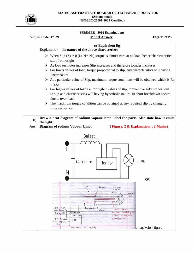
b) Draw a neat diagram of sodium vapour lamp. label the parts. Also state how it emits the light.
Ans: Diagram of sodium Vapour lamp: ( Figure: 2 & Explanation: : 2 Marks)
OR
or equivalent figure
MAHARASHTRA STATE BOARAD OF TECHNICAL EDUCATIOD (Autonomous)
(ISO/IEC-27001-2005 Certified)
SUMMER– 2016 Examinations
Subject Code: 17329 Model Answer Page 12 of 25
Following reason for it emits the light: When the lamp is turned on, a high voltage at staring is applied across two
electrodes, to initiate an arc which discharges and vaporizes xenon /neon gas (starting gas), sodium and mercury.
The energized metal atoms emit light. After 2 to 5 minutes lamp will glow 100 %. For running the lamp low voltage of about 165V is sufficient. The color of light produce is yellowish.
c) Define earthing. State the necessity of earthing of an electrical motors and appliances. Ans: Meaning of earthing: ( 2 Marks)
Connecting the metallic frame of the electrical machines /any electrical equipment body etc to ground is known as earthing. Earthing protected against the electric shock.
Necessity Earthing of electrical motors and appliances: ( 2 Marks)
The purpose of earthing is to minimize risk of receiving an electric shock if touching metal parts when a leakage current is present.
Earthing is to ensure safety or Protection of electrical equipment and Human by
discharging the electrical leakage current to the earth.
OR Earthing is provided to protect human from shocks due to leakage current. Earthing provides protection to the electrical motors and appliances. due to leakage
current. Earthing provides protection to the electrical motors to protect against over voltage
(Neutral earthing)
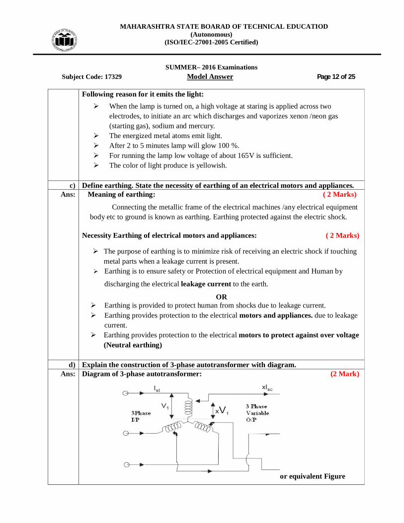
d) Explain the construction of 3-phase autotransformer with diagram. Ans: Diagram of 3-phase autotransformer: (2 Mark)
or equivalent Figure

MAHARASHTRA STATE BOARAD OF TECHNICAL EDUCATIOD (Autonomous)
(ISO/IEC-27001-2005 Certified)
SUMMER– 2016 Examinations
Subject Code: 17329 Model Answer Page 13 of 25
Explanation of construction of 3-Ph Auto Transformer:- (2 Mark)
It is a transformer with three winding.
Autotransformer is a special transformer in which a part of winding is common for
the primary and secondary windings.
It consists of only three winding wound on a laminated magnetic core, with a rotary
movable contact.
Autotransformer can operate as a step down or a step up transformer.
e) With neat sketch explain Direct ON line starter for 3-phase Induction motor. Ans: Circuit diagram of direct on line starter: (2 Mark)
OR
or equivalent figure
Explanation: (2 Mark)
To start, the contactor is closed, applying full line voltage to the motor windings. The motor will draw a very high inrush current for a very short time, the magnetic field in the iron, and then the current will be limited to the Locked Rotor Current of the motor.
The motor will develop Locked Rotor Torque and begin to accelerate towards full speed.
As the motor accelerates, the current will begin to drop, but will not drop significantly until the motor is at a high speed, typically about 85% of synchronous speed. The actual starting current curve is a function of the motor design, and the terminal voltage, and is totally independent of the motor load.

MAHARASHTRA STATE BOARAD OF TECHNICAL EDUCATIOD (Autonomous)
(ISO/IEC-27001-2005 Certified)
SUMMER– 2016 Examinations
Subject Code: 17329 Model Answer Page 14 of 25
The motor load will affect the time taken for the motor to accelerate to full speed
and therefore the duration of the high starting current, but not the magnitude of the
starting current.
Provided the torque developed by the motor exceeds the load torque at all speeds
during the start cycle, the motor will reach full speed. If the torque delivered by the
motor is less than the torque of the load at any speed during the start cycle, the
motor will stops accelerating.
If the starting torque with a DOL starter is insufficient for the load, the motor must
be replaced with a motor which can develop a higher starting torque.
f) Explain the functions of enclosures and mountings used for electrical drives. Ans: (functions of Enclosures: 2 Marks & Method of mounting: 2 Marks)
Function of motor enclosure:-
1. It protects the operator against the contact with live and moving parts. 2. It provides protection to internal parts of motor against mechanical injury. 3. It gives mechanical support. 4. It provides protection against entry of moisture, dirt, dust particles inside the
motor. 5. Main purpose of enclosure is to fold the machines.
Method of mounting: (2 Marks)
1. Open type enclosure: where motor is installed
2. Screen protected enclosure: Provided for rotating parts for better protection &
where motor is installed
3. Drip (moisture) proof enclosure: Water pumping station, Motor on ship, sub-
miscible motor etc
4. Flame (fire) proof enclosure: Chemical plants, Mines etc
5. Totally enclosed type enclosure: Saw mill, stone crushing plant, coal handling
plant, cement manufacturing plant and cotton industry etc.
Pipe ventilation totally enclosed type enclosure : Stone crushing, coal handling
plant, cement industry, cotton industry, saw mill etc
----------------------------------------------- (END PART-I) ---------------------------------------------------

MAHARASHTRA STATE BOARAD OF TECHNICAL EDUCATIOD (Autonomous)
(ISO/IEC-27001-2005 Certified)
SUMMER– 2016 Examinations
Subject Code: 17329 Model Answer Page 15 of 25
SECTION — II
Q.4 Attempt any NINE of the following: 18 Marks a) Define insulator and semiconductor with example.
Ans: Insulator: (1/2 Mark for definition and 1/2 Mark for 1 example)
In most solid materials the outermost electrons are so tightly bound that there are no free
electrons that can freely move throughout the material. These materials are known as
insulators. .OR In energy band diagram, where there is large gap (band gap) present between
conduction band and valenceband, it is called as insulator. e.g. glass, paper, air, etc.
Semiconductor: (1/2 Mark for definition and 1/2 Mark for 1 example)
The materials which have four electrons in the outermost orbit of the atoms are called as
semiconductor. There are no free electrons in semiconductor. OR In energy band diagram,
where there is band gap of 1.1eV or 0.67eV for Si & Ge respectively present between
conduction band and valence band ,it is called as semiconductor. e.g. Silicon, Germanium etc.
b) Draw the symbols of: i) Photodiode ii) Zener diode iii) UJT iv) PN junction diode Ans: i) Symbol of photodiode: (1/2 Mark for each symbol)
(ii) Symbol of Zener diode:
(iii )Symbol of UJT:
(iv) Symbol of PN junction diode:-

MAHARASHTRA STATE BOARAD OF TECHNICAL EDUCATIOD (Autonomous)
(ISO/IEC-27001-2005 Certified)
SUMMER– 2016 Examinations
Subject Code: 17329 Model Answer Page 16 of 25
c) What is rectifier ? What are its types? Ans: Rectifier: ( 1 Mark)
A rectifier is an electrical device that converts alternating current (AC), which periodically reverses direction, to direct current (DC), which flows in only one direction.
Types: ( 1 Mark) 1) Half wave rectifier
2) Center tap full wave rectifier
3) bridge rectifier
d) Draw the labelled symbol of OP-AMP. Ans: Symbol of OP-AMP: ( 2 Marks)
e) Define filter. State the function of filter.
Ans: Filter Definition: ( 1 Mark) A filter is used to remove unwanted AC components or ripple present on the output of rectifier.
Function: ( 1 Mark) 1) A filter is used to get pure DC from pulsating DC.
2) It removes ripples present on output of rectifier.
f) Draw the symbol of PNP and N PN transistor and state one application of transistor. Ans: Symbol of PNP and N PN transistor: (1/2 Mark for each symbol)
Applications: 1) As amplifier 2) As Switch. (1 Mark for any one application)

MAHARASHTRA STATE BOARAD OF TECHNICAL EDUCATIOD (Autonomous)
(ISO/IEC-27001-2005 Certified)
SUMMER– 2016 Examinations
Subject Code: 17329 Model Answer Page 17 of 25 g) Draw the energy band diagram for conductor and semiconductor.
Ans: Energy band diagram for conductor and semiconductor : (1 Mark for each diagrm) Conductor Semiconductor
h) Draw the circuit diagram of single stage CB amplifier.
Ans: Circuit diagram of single stage CB amplifier: ( 2 Mark)
i) Name the universal gates. Draw their symbol.
Ans: Name of universal gates: (1 Mark for each name & symbol)
i)NOR gate ii) NAND gate :
j) List two ideal characteristics of operational amplifier.
Ans: Ideal characteristics of operational amplifier: (Any two characteristics 2 Marks ) 1) Infinite open-loop gain G = vout / v. ... 2) Infinite input impedance Rin, and so zero input current.
MAHARASHTRA STATE BOARAD OF TECHNICAL EDUCATIOD (Autonomous)
(ISO/IEC-27001-2005 Certified)
SUMMER– 2016 Examinations
Subject Code: 17329 Model Answer Page 18 of 25
3) Zero input offset voltage. 4) Infinite output voltage range. 5) Infinite bandwidth with zero phase shift and infinite slew rate. 6)Zero output impedance R. ... 7) Zero noise.
k) Convert (100)10 to binary
Ans: Ans : (100)10 =(1100100)2 (2 Marks)
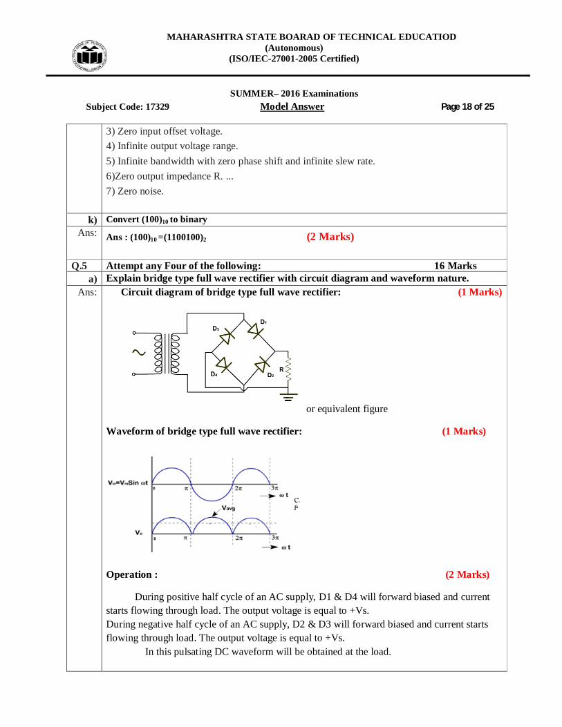
Q.5 Attempt any Four of the following: 16 Marks a) Explain bridge type full wave rectifier with circuit diagram and waveform nature.
Ans: Circuit diagram of bridge type full wave rectifier: (1 Marks)
or equivalent figure
Waveform of bridge type full wave rectifier: (1 Marks)
Operation : (2 Marks)
During positive half cycle of an AC supply, D1 & D4 will forward biased and current starts flowing through load. The output voltage is equal to +Vs. During negative half cycle of an AC supply, D2 & D3 will forward biased and current starts flowing through load. The output voltage is equal to +Vs. In this pulsating DC waveform will be obtained at the load.
MAHARASHTRA STATE BOARAD OF TECHNICAL EDUCATIOD (Autonomous)
(ISO/IEC-27001-2005 Certified)
SUMMER– 2016 Examinations
Subject Code: 17329 Model Answer Page 19 of 25
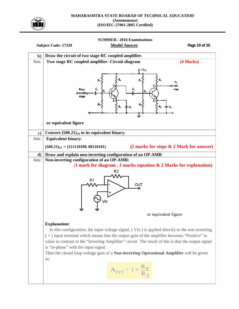
b) Draw the circuit of two stage RC coupled amplifier. Ans: Two stage RC coupled amplifier- Circuit diagram (4 Marks)
or equivalent figure
c) Convert (500.21)10 to its equivalent binary. Ans: Equivalent binary:
(500.21)10 = (111110100. 00110101) (2 marks for steps & 2 Mark for answer)
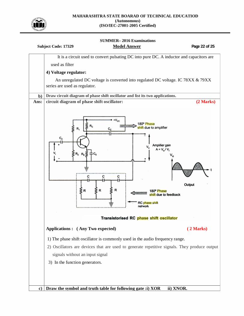
d) Draw and explain non-inverting configuration of an OP-AMR Ans: Non-inverting configuration of an OP-AMR:
(1 mark for diagram , 1 marks equation & 2 Marks for explanation)
or equivalent figure
Explanation: In this configuration, the input voltage signal, ( Vin ) is applied directly to the non-inverting ( + ) input terminal which means that the output gain of the amplifier becomes “Positive” in value in contrast to the “Inverting Amplifier” circuit The result of this is that the output signal is “in-phase” with the input signal. Then the closed loop voltage gain of a Non-inverting Operational Amplifier will be given as:

MAHARASHTRA STATE BOARAD OF TECHNICAL EDUCATIOD (Autonomous)
(ISO/IEC-27001-2005 Certified)
SUMMER– 2016 Examinations
Subject Code: 17329 Model Answer Page 20 of 25
e) With the help of a neat diagram, explain the working and characteristics of LED. Ans: Diagram of LED: (1 Mark for diagram , 1 Mark characteristics & 2 Marks for
explanation)
or equivalent figure A light emitting diode (LED) is known to be one of the best optoelectronic devices out of the lot. The device is capable of emitting a fairly narrow bandwidth of visible or invisible light when its internal diode junction attains a forward electric current or voltage. The visible lights that an LED emits are usually orange, red, yellow, or green. The invisible light includes the infrared light. The P-N junction emits light when energy is applied on it. This phenomenon is generally called electroluminance, which can be defined as the emission of light from a semi-conductor under the influence of an electric field. The charge carriers recombine in a forward P-N junction as the electrons cross from the N-region and recombine with the holes existing in the P-region. Free electrons are in the conduction band of energy levels, while holes are in the valence energy band. Thus the energy level of the holes will be lesser than the energy levels of the electrons. Some part of the energy must be dissipated in order to recombine the electrons and the holes. This energy is emitted in the form of heat and light. Characteristics of LED:
or equivalent figure

MAHARASHTRA STATE BOARAD OF TECHNICAL EDUCATIOD (Autonomous)
(ISO/IEC-27001-2005 Certified)
SUMMER– 2016 Examinations
Subject Code: 17329 Model Answer Page 21 of 25
f) Draw the logic symbol and write the truth table for each of the following :i) AND gate ii) NOT gate.
Ans: i) AND gate: ( 2 Marks)
ii) NOT gate: ( 2 Marks)
Q.6 Attempt any Four of the following: 16 Marks a) Draw and explain block diagram of regulated power supply.
Ans: Block diagram of regulated power supply: ( 2 Mark)
Explanation : ( 2 Mark)
1) Transformer:
It Converts an AC input source to AC required output without changing frequency. The
transformer is step up or step down transformer.
2) Rectifier:
It is a circuit which is used to convert AC into pulsating DC. A rectifying diode is used.
3) Filter:
MAHARASHTRA STATE BOARAD OF TECHNICAL EDUCATIOD (Autonomous)
(ISO/IEC-27001-2005 Certified)
SUMMER– 2016 Examinations
Subject Code: 17329 Model Answer Page 22 of 25
It is a circuit used to convert pulsating DC into pure DC. A inductor and capacitors are
used as filter
4) Voltage regulator:
An unregulated DC voltage is converted into regulated DC voltage. IC 78XX & 79XX series are used as regulator.
b) Draw circuit diagram of phase shift oscillator and list its two applications. Ans: circuit diagram of phase shift oscillator: (2 Marks)
Applications : ( Any Two expected) ( 2 Marks) 1) The phase shift oscillator is commonly used in the audio frequency range.
2) Oscillators are devices that are used to generate repetitive signals. They produce output
signals without an input signal
3) In the function generators.
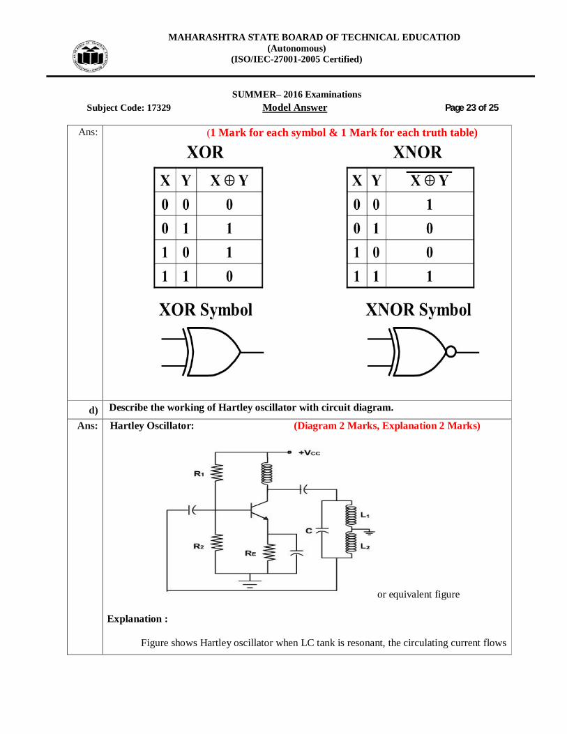
c) Draw the symbol and truth table for following gate :i) XOR ii) XNOR.
MAHARASHTRA STATE BOARAD OF TECHNICAL EDUCATIOD (Autonomous)
(ISO/IEC-27001-2005 Certified)
SUMMER– 2016 Examinations
Subject Code: 17329 Model Answer Page 23 of 25
Ans: (1 Mark for each symbol & 1 Mark for each truth table)
d) Describe the working of Hartley oscillator with circuit diagram.
Ans: Hartley Oscillator: (Diagram 2 Marks, Explanation 2 Marks)
or equivalent figure
Explanation :
Figure shows Hartley oscillator when LC tank is resonant, the circulating current flows
MAHARASHTRA STATE BOARAD OF TECHNICAL EDUCATIOD (Autonomous)
(ISO/IEC-27001-2005 Certified)
SUMMER– 2016 Examinations
Subject Code: 17329 Model Answer Page 24 of 25
through L1 in series with L2. Thus, equivalent inductance is L = L1 + L2.
In the oscillator, the feedback voltage can be developed by the inductive voltage
divider, L1 & L2. Since output voltage appears across L1 and feedback voltage across L2, the
feedback fraction can be given by
β = V / Vout = XL2 / XL1 = L2 / L1
As usual, loading effect of the base is ignored. For the oscillations to begin, the voltage gain should be greater than 1/ β. The frequency of oscillation can be given by
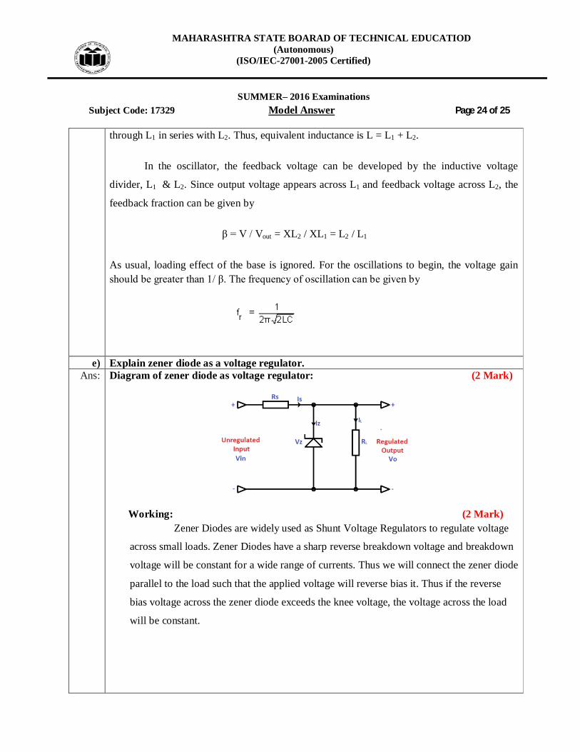
e) Explain zener diode as a voltage regulator.
Ans: Diagram of zener diode as voltage regulator: (2 Mark)
Working: (2 Mark) Zener Diodes are widely used as Shunt Voltage Regulators to regulate voltage
across small loads. Zener Diodes have a sharp reverse breakdown voltage and breakdown
voltage will be constant for a wide range of currents. Thus we will connect the zener diode
parallel to the load such that the applied voltage will reverse bias it. Thus if the reverse
bias voltage across the zener diode exceeds the knee voltage, the voltage across the load
will be constant.

MAHARASHTRA STATE BOARAD OF TECHNICAL EDUCATIOD (Autonomous)
(ISO/IEC-27001-2005 Certified)
SUMMER– 2016 Examinations
Subject Code: 17329 Model Answer Page 25 of 25 f) Explain OP-AMP as subtractor.
Ans: 1 Mark for diagram , 1 marks equation & 2 Marks for explanation)
or equivalent figure
By connecting one voltage signal onto one input terminal and another voltage signal
onto the other input terminal the resultant output voltage will be proportional to the
“Difference” between the two input voltage signals of V1 and V2.
Then differential amplifiers amplify the difference between two voltages making this
type of operational amplifier circuit a Subtractor unlike a summing amplifier which adds or
sums together the input voltages. This type of operational amplifier circuit is commonly known
as a Differential Amplifier configuration.
)( 12
1
VVRR
V fout
---------------------------------------------------- END-----------------------------------------------------------