mansouri saffari 2015
DESCRIPTION
Recent Research published in ASIAN JOURNAL OF CIVIL ENGINEERINGTRANSCRIPT

ASIAN JOURNAL OF CIVIL ENGINEERING (BHRC) VOL. 16, NO. 4 (2015)
PAGES 451-466
NEW MATHEMATICAL MODELING OF STEEL PANEL ZONE
WITH THIN TO THICK COLUMN FLANGES
I. Mansouri1 and H. Saffari2 1Department of Civil Engineering, Birjand University of Technology, Birjand, Iran,
2Department of Civil Engineering, Shahid Bahonar University of Kerman, Kerman, Iran
Received: 15 October 2014; Accepted: 12 January 2015
ABSTRACT
The response of a steel moment resisting frame (MRF) depends on the specifications of its
main components, namely the columns, beams and connections. One important connection
element which can significantly affect frame behavior is the panel zone (PZ). The PZ is
described to be an element mainly subjected to shear stresses and its failure mode is often
governed by shear yielding. Several analytical models for PZ behavior exist, in terms of
shear force-shear distortion relationships. Among these models, the Krawinkler PZ model is
the most popular one which is used in codes. Some studies have pointed out that
Krawinkler’s model gives good results for the range of thin to medium column flanges
thickness. The model presented here is applicable to both thin and thick column flange.
More than four-hundred beam-column connections are included in the parametric study,
with varied parameters being: beam depth, column flange thickness, column web thickness,
and beam flange thickness. The elastic stiffness, shear yield strength and ultimate shear
strength of the PZ obtained from FE analysis, are compared with those obtained from
available mathematical models to show differences, especially in the case of thick column
flanges. In the paper a simple mathematical model for estimating the stiffness and shear
strength in the PZ is introduced. In this model both shear and bending deformations are
considered. A comparison between the results of proposed method herein with FE analyses
shows the average error is significantly reduced which demonstrates the accuracy,
efficiency, and simplicity of the proposed model.
Keywords: Panel zone; shear strength; beam-column connection; mathematical model;
FEM analysis.
1. INTRODUCTION
In linear analysis, the beam-column joint is treated as a point at the intersection of the beam
E-mail address of the corresponding author: [email protected] (H. Saffari)
Archive
of S
ID
www.SID.ir

I. Mansouri and H. Saffari
452
and the column and generally the joint stiffness is formulated based on the clear span of the
member. To further the calculation of the joint deformations in the structure without using
additional elements, a reduced rigid end offset as a fraction of the actual joint size at both
ends of the beams and columns can be defined [1]. Using this approximate approach it is
difficult to determine the appropriate fraction of actual joint sizes for the member end offsets
to account for the flexibilities of these joints. In addition, in nonlinear analysis, the beam-
column joint can yield in shear due to the large moment transferred through the joint. The
hinge formation pattern of the structure will be erroneous without considering the relative
flexibilities of joints with respect to other elements; therefore, a separate element that
realistically specifies the behavior of the beam-column joint is needed. For this aim, a panel
zone (PZ) joint element for modeling steel beam-column joints for nonlinear analyses of
moment resisting frames was developed.
In the 1994 Northridge earthquake, brittle fractures in beam-column connection areas
occurred causing considerable damage. Following this event, various related American
institutions have been conducting experimental researches on the behavior of steel moment
connection and developing analytical modeling techniques. In a modified pre-Northridge
connection, now called the post-Northridge connection, there are only two sources to
dissipate seismic energy, the beam-end and the PZ [2-4].
Depending on the basis for computing the required shear strength, PZs can behave quite
differently. If the PZ is weak relative to the girder flexural strength, most of inelastic
behavior may take place within the connection, while stronger PZs will allow shared energy
dissipation between the joint and the connected girders. Specifically, a weak PZ will put
relatively high stress and strain concentrations at the location of the kink in the column
flange adjacent to the critical girder flange-to-column welds. This may increase the
potential for low-cycle fatigue and brittle fracture. A strong PZ may increase the stress and
strain concentrations in the girder, on the other side of the critical girder flange-to-column
welds and at the critical weld access hole area. It is presently not clear whether a weak or
strong PZ is best for the overall resistance of the connection [5].
The PZ, which is the region in the column web defined by the extension of the beam
flange lines into the column (Fig. 1), is known to have stable hysteretic and ductile
properties [6,7]. These features make the PZ an attractive component for energy dissipation
in steel MRFs under seismic loading.
At the beginning of the 1970’s, studies were conducted to understand the inelastic
behavior of joints in moment-resisting frames [7,8]. In order to figure out different loading
regimes, several loading conditions were simulated on the tests, whereby gravity and cyclic
seismic loads were applied to different sub-assemblages. Several years later, a number of
test were performed by Popov et al. [9] in order to verify the extreme loading conditions on
joints and to study the cyclic behavior of large beam assemblies. Tsai et al. [10] carried out
further testing on similar joint subassemblies. The main purpose was to study the
performance of seismic steel beam-column moment joints. The research concluded that the
PZ has a significant effect on joint behavior and that the inelastic deformation capacity of
the joint can be increased if the PZ is correctly proportioned. Hence, among the parameters
studied in both studies was the design criteria used for the PZ.
Archive
of S
ID
www.SID.ir

NEW MATHEMATICAL MODELING OF STEEL PANEL ZONE WITH THIN TO ...
453
Figure 1. Joint panel of an interior beam-to-column connection
It has been demonstrated analytically and experimentally that high shear forces are often
developed in a joint panel, and the PZ shear and deformation effect will have a pronounced
influence on frame behavior [11].
Among several analytical models, the Krawinkler joint model is used in codes and
guidelines (e.g. [12,13]); however, this model gives good results for joints with thin to
medium column flange thicknesses [11]. In this paper, using an extensive nonlinear finite
element analysis, a new sample mathematical model is proposed to cover the range of thin to
thick column flanges. In the recent years several studies have been done to evaluate the
behavior of panel zones [14-17].
2. EXİSTİNG MATHEMATİCAL MODELS
Mathematical models for the behavior of the steel PZ in terms of shear force-shear distortion
)( V relationships have been suggested by many researchers (e.g., [18-20] based on either
experimental observations or modifications to pre-existing models. This representation can
be carried out by means of different relationships and levels of precision. Techniques for
modeling the beam-column connections in steel structures are classified in the following
sections [21,22].
2.1 Linear centerline model
To design structures or evaluate the performance of existing buildings, two criteria are
needed, the strength of members and the stiffness of system. The linear elastic model using
the central line model is suitable for designing a steel moment resisting frame. Although the
model shows appropriate results for design, it cannot accurately forecast the distribution of
the inelastic member forces created by the dynamic load.
Archive
of S
ID
www.SID.ir

I. Mansouri and H. Saffari
454
2.2 Elastic model with panel zone
Fig. 2 shows the scissors model, which includes a PZ. In this model, beams and columns are
connected via rigid links in a PZ, and the crossroad hinge is connected via a spring with the
stiffness of the PZ. Since this model contains dimension and stiffness of the PZ, it forecasts
more accurately the distribution of shear forces, flexural moments, and axial forces than the
above model.
2.3 Nonlinear centerline model
The inelastic model is useful in assessing the behavior of existing buildings. To conduct
nonlinear analysis, most commercial programs, as shown in Fig. 3, connect springs with
nonlinear features with section properties of beams and columns.
Figure 2. Joint panel of an interior beam-to-column connection
Figure 3. Nonlinear Centerline Model
Archive
of S
ID
www.SID.ir

NEW MATHEMATICAL MODELING OF STEEL PANEL ZONE WITH THIN TO ...
455
2.4 Nonlinear model with panel zone
The nonlinear analytical models, which include PZs, are categorized into three techniques.
The first model is the scissors model in Fig.2 containing nonlinear property for a spring
element. The second model [23], shown in Fig. 4, uses two springs having a PZ stiffness and
the average strength of the PZ and the beams.
Figure 4. Shi’s model [23]
Although this model can express stiffness and strength of a PZ, it cannot accurately
express its shear deformation without expression of the accurate dimension of the PZ. The
third model, developed by Krawinkler [24], models a PZ into 8 rigid bodies (Fig. 5).
Actually, this model shows the least difference between the actual behavior of a structure
and the behavior of the analytical model.
Figure 5. Krawinkler model [24]
Archive
of S
ID
www.SID.ir

I. Mansouri and H. Saffari
456
2.5 Characteristics of original Krawinkler model
The Krawinkler joint model [18] is a simple and useful model to describe the shear force-
shear distortion )( V behavior of a joint panel. Physically, this is the only model that
makes sense. The others seem either much more complicated (for no reason) or physically,
they don't make sense. AISC and FEMA 355D specifications also include this model in the
PZ design.
The model is simple and gives generally conservative results. Krawinkler's model is the
most simple model (requires the fewest number of parameters) that completely describes PZ
behavior in steel moment frames. One could develop a more complicated model with
increased number of parameters, and calibrate that model to better fit experimental response.
However, complicated models are, by nature, more cumbersome to use. In many cases, even
if extra effort is spent calibrating a model to a particular test, the same model will not work
as well for another test result. For these reasons, Krawinkler's model is the model of choice.
The control values for the model are given as follows:
pcypc
y
eff
y
y tdFtdF
AF
V 55.0)95.0(33
(1)
where Vy is the PZ shear yield strength, Fy is the yielding strength of the PZ, Aeff is the
effective shear area, dc is the depth of the column, and tp is the panel thickness (thickness of
the column web, plus the doubler plate thickness, if present). The corresponding yield
distortion, )( V , is given as:
3G
Fy
y (2)
The elastic stiffness, Ke, of the PZ can then be written as:
GtdV
K pc
y
y
e 95.0
(3)
where G is the shear modulus of the column material.
When the panel shear exceeds Vy, the elastic stiffness contribution from the panel web is
assumed to be zero. The stiffness contribution when V > Vy can only come from the
resistance of the elements surrounding the panel. This post-yield panel stiffness, Kp, is given
as [18]:
b
cfc
b
cfc
pd
Gtb
d
GtbK
95.0
04.1095.122
(4)
where bc and tcf are the width and thickness of the column flange, respectively, and db is
the beam depth.
Archive
of S
ID
www.SID.ir

NEW MATHEMATICAL MODELING OF STEEL PANEL ZONE WITH THIN TO ...
457
If it is assumed that the post-yield stiffness of the joint panel as given by Eq. (4) is valid
for the rangeyy 4 , the ultimate strength, Vp, of a joint panel is given by:
pcb
cfc
pcy
e
p
yptdd
tbtdF
K
KVV
23
155.03
1 (5)
This strength is assumed to be reached at a value ofyp 4 . Beyond
p an appropriate
value of the strain-hardening can be assumed to fully define the trilinear shear force-shear
deformation relationship of the PZs (α is the ratio between post-yield tangent and initial
elastic tangent). A schematic plot of V versus for the Krawinkler panel model is shown in
Fig. 6.
Figure 6. Shear force-distortion response of the Krawinkler joint panel model
3. FINITE ELEMENT MODEL
To determine the PZ model behavior, the effects of PZ strength and stiffness on connection
response are parametrically studied using finite element models. Version 14.0 of the general
purpose nonlinear finite element program ANSYS [25] was used to model 432 fully
restrained bolted web-welded flange beam-to-column moment connections. The whole
computational volume for the present parametric study is estimated to be of the order of (4
specimens) × (6 column flange thicknesses) × (6 column web thicknesses) × (3 beam flange
thicknesses) = 432 finite element analysis. Shell-element models were prepared to study
local and global instabilities in the connections because such models are computationally
more efficient than solid-element models for this purpose [26]. A four-node shell element
(Shell 181 element with six degrees of freedom at each node) has been used to model the
Archive
of S
ID
www.SID.ir

I. Mansouri and H. Saffari
458
specimens. Such elements were successfully employed by El-Tawil et al. [27] for a related
study funded by the SAC Joint Venture. The size of the finite element mesh varied over the
length and height of the specimen. A fine mesh was used near the connection of the beam to
the column. A coarser mesh was used elsewhere in order to reduce the computational efforts.
Beam flanges were modeled using 5 layers of elements through the flange depth and 10
elements across the flange half-width. The distribution of geometric imperfections matched
the first eigenvector of the loaded connection configuration. The maximum imperfection
was chosen as one percent of the beam flange thickness.
Two lines of nodes at each end of the column were restrained against translation only
(i.e., a pinned connection) to approximately replicate the support conditions used for the
laboratory tests. A vertical displacement history was imposed at the free end of the beam
using the displacement control feature in ANSYS.
Since verification is necessary for numerical models, before performing the parametric
study some well-known experimental programs were considered to verify the finite element
modeling methodology and general assumptions on the nonlinear analysis.
3.1 Verification study
To verify the accuracy of finite element modeling, specimens SAC3, SAC5 and SAC7 (Fig.
7) of reference [28] and specimen SPE1 of reference [29] was remodeled using finite
element method. Shown in Fig. 8 is a comparison between analytical and experimental
results. As this figure shows, the analytical result is in good agreement with experimental
result.
Archive
of S
ID
www.SID.ir
NEW MATHEMATICAL MODELING OF STEEL PANEL ZONE WITH THIN TO ...
459
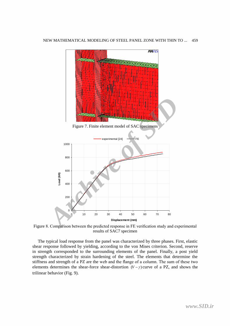
Figure 7. Finite element model of SAC specimens
Figure 8. Comparison between the predicted response in FE verification study and experimental
results of SAC7 specimen
The typical load response from the panel was characterized by three phases. First, elastic
shear response followed by yielding, according to the von Mises criterion. Second, reserve
in strength corresponded to the surrounding elements of the panel. Finally, a post yield
strength characterized by strain hardening of the steel. The elements that determine the
stiffness and strength of a PZ are the web and the flange of a column. The sum of these two
elements determines the shear-force shear-distortion )( V curve of a PZ, and shows the
trilinear behavior (Fig. 9).
0
200
400
600
800
1000
0 10 20 30 40 50 60 70 80
Displacement (mm)
Lo
ad
(k
N)
experimental [24] FE
Archive
of S
ID
www.SID.ir

I. Mansouri and H. Saffari
460
(a) column web (b) column flange (c) trilinear PZ
Figure 9. Moment-rotation Behavior of PZ
The Krawinkler PZ model proposes relationships between PZ shear force and
deformation for monotonic loading. These relationships have been used as a basis of
mathematical models for nonlinear rotational springs representing the PZ. As it can be seen
in Figs. 10a and 10b, Krawinkler’s model gives good results for joints with thin to medium
thickness column flanges.
However, it is pointed out by Krawinkler that a new model might be needed for joints
with thick column flanges [18]. This issue can be observed in Fig. 11. This paper proposes a
model that considers both bending and shear deformation, covering the range of thin to thick
column flanges.
(a)
0
200
400
600
800
1000
0 0.005 0.01 0.015 0.02 0.025
γ (rad)
Vp
z (k
N)
Krawinkler FE Present model
Archive
of S
ID
www.SID.ir

NEW MATHEMATICAL MODELING OF STEEL PANEL ZONE WITH THIN TO ...
461
(b)
Figure 10. Comparison of the FE model and Krawinkler’s model (a) with tcf 16.3 mm (b) with tcf
21.7 mm
Figure 11. Comparison of the FE model and Krawinkler’s model with tcf 48 mm
4. PROPOSED ANALYTİCAL MODEL
Column flange thickness effects PZ yield shear and elastic stiffness [30]. In this study, to
find the mathematical model of PZ behavior both bending and shear deformations of the PZ
are considered. For this purpose, it is assumed that the equivalent of column web and
column flanges (Fig. 12a) is similar to an element shown in Fig. 12b.
0
200
400
600
800
1000
1200
0 0.002 0.004 0.006 0.008 0.01
γ (rad)
Vp
z (k
N)
Krawinkler FE Present model
0
1000
2000
3000
4000
0 0.005 0.01 0.015 0.02 0.025
Shear distortion (rad)
Vp
z (
kN
)
FE Krawinkler
Archive
of S
ID
www.SID.ir

I. Mansouri and H. Saffari
462
Figure 12. Panel zone (a) complex of column web and column flanges (b) equivalent model
In order to achieve the stiffness of PZ the energy method and a simplified model are used
(Fig. 12b). Based on stiffness concept and using the method of least work the external
displacement, Δ, is given by:
122
)(
220 0
22
0
2
0
2
b bbb d ddd
GA
dxK
EI
dxKxM
KGA
dxV
EI
dxm
K (6)
where m = internal moment in the member, expressed as a function of x; E = modulus of
elasticity of the steel; I = moment of inertia of cross-sectional area; V = internal shear in the
member, expressed as a function of x; A = cross-sectional area of the member, and η = form
factor for the cross-sectional area.
After simplifying:
132
32
GA
Kd
EI
Kd
EI
Md bbb
(7)
and it can be written that:
bd
EI
dxKxM
M
U
0
0)(
(8)
therefore from Eq. (8):
20
2
2
bbb KdM
EI
Kd
EI
Md (9)
Archive
of S
ID
www.SID.ir

NEW MATHEMATICAL MODELING OF STEEL PANEL ZONE WITH THIN TO ...
463
Substituting Eq. (9) into Eq. (7), the stiffness, K, is given as follows:
EI
d
GA
dK
bb
12
13
(10)
Often, the shear force-shear distortion )( V relation is used to investigate the behavior
of PZ. Thus, the Eq. (10) is multiplied by db and the related stiffness can be written as:
)(12
112
1
122
GAEI
d
GA
EI
d
GA
Kbb
(11)
Replacing E = 2.6G, and 2/2
ccf dAI (Acf =bctcf) in Eq. (11), the modified initial
stiffness, Ke,mod, of the panel component is expressed as follows:
2mod,
)(064.01c
b
cf
e
d
d
A
A
GAK
(12)
if A = Aw (area of the web), then the parameter η is equal to 1 [31]. A comparison
between results of 432 finite element models and above formulation showed that if Aw is
considered as dctcw, the following equation is better matched with results obtained from FE,
therefore:
2mod,
)(064.01c
b
cf
w
we
d
d
A
A
GAK
(13)
Consequently, the following relationships can be used to make the mathematical model:
yey KV mod,mod, (14)
mod,
mod,mod,
31
e
p
ypK
KVV (15)
it is assumed that strain hardening begins at y 4 . The results show that the modified
relations also depend on the ratios of web area to flange area (Aw/Acf) and beam depth to
column depth (db/dc).
A comparison between this mathematical model and all of 432 FE models shows the
average and maximum error among are equal to 1.15% and 8.8%, respectively. As an
example Fig. 13 shows a sample that using these corrections (Eqs. 13 through 15), the
proposed trilinear model is compatible with FE results, especially in the case of thick
Archive
of S
ID
www.SID.ir

I. Mansouri and H. Saffari
464
column flanges.
Also, the obtained errors of the proposed mathematical model and other mathematical
models in comparison with 432 FE models are listed in Table 1 and Table 2 to show the
accuracy of the present model.
Figure 13. Comparison of the FE model, Krawinkler’s model and proposed model with tcf 48 mm
Tables 1 and 2 show that the model introduced in the present work has better
performance as compared to the other models; especially in comparison with initial model
(Krawinkler’s model) the proposed model has significantly reduced the error.
Table 1: Errors in PZ elastic stiffness of different mathematical models in comparison with 432
FE models
elastic stiffness Ke
model Krawinkler scissors Shi Lu proposed model
average error (%) 18.05 18.05 16.94 12.77 1.15
max error (%) 31.95 31.95 24.55 22.72 8.8
Table 2. Errors in PZ shear ultimate strength of different mathematical models in comparison
with 432 FE models
ultimate shear
strength Vp
model Krawinkler scissors Shi Lu proposed model
average error (%) 16.61 16.61 15.04 14.73 1.08
max error (%) 25.66 - 18.64 17.11 6.83
0
1000
2000
3000
4000
0 0.005 0.01 0.015 0.02 0.025
Shear distortion (rad)
Vp
z (
kN
)
Present model FE Krawinkler
Archive
of S
ID
www.SID.ir

NEW MATHEMATICAL MODELING OF STEEL PANEL ZONE WITH THIN TO ...
465
5. CONCLUSIONS
The research performed and presented in this paper aimed at inquiring the development of a
panel zone model which eliminates the limitations of other mathematical models. More than
four-hundred finite element modeling have been carried out in order to present the new
model. In this model, both bending and shear deformation modes are considered which leads
to more accurate results. The proposed model is simple and can be used for both thin and
thick column flanges. The results show that the modified relations also depend on the ratios
of web area to flange area and beam depth to column depth. The developed PZ model
permits a realistic representation of the behavior of the PZ, especially in the case of thick
column flanges.
REFERENCES
1. Tsai KC, Popov EP. Steel beam-column joints in seismic moment resisting frames,
EERC Report No. UCB/EERC-88/19, University of California Berkeley, CA, 1988.
2. Hedayat AA, Celikag M. Enhancement of panel zone (PZ) contribution to the ductility
of post-Northridge welded connections, WSEAS Transactions on Applied and
Theoretical Mechanics, 3(2008) 165-74.
3. Mehrabian A, Haldar A. Mathematical modelling of a "post-Northridge" steel
connection, International Journal of Modelling Identification and Control, 2(2007)
195-207.
4. Saffari H, Hedayat AA, Nejad MP. Post-Northridge connections with slit dampers to
enhance strength and ductility, Journal of Constructional Steel Research, 80(2013) 138-52.
5. Lee D, Cotton S, Dexter RJ, Hajjar JF, Ye Y, Ojard SD. Column stiffener detailing and
panel zone behavior of steel moment frame connections, Report No. ST-01-3.2,
Department of Civil Engineering, University of Minnesota, Minneapolis, MN, 2002.
6. Krawinkler H, Bertero VV, Popov EP. Inelastic behavior of steel beam-to-column
subassemblages, Report No. EERC 71/07, University of California Berkeley, CA, 1971.
7. Fielding DJ, Huang JS. Shear in steel beam-to-column connections, Welding Journal,
50(1971) 313-26 (research supplement).
8. Bertero VV, Popov EP, Krawinkler H. Beam-column subassemblies under repeated
load, Journal of the Structural Division, 98(1972) 1137-59.
9. Popov EP, Amin NR, Louie JJC, Stephen RM. Cyclic behavior of large beam-column
assemblies, Earthquake Spectra, 1(1985) 203-38.
10. Tsai KC, Wu S, Popov EP. Cyclic performance of steel beam-column moment joints,
Engineering Structures, 17(1995) 596-602.
11. Chen WF, Lui EM. Stability Design of Steel Frames, Florida, CRC Press, 1991.
12. AISC. Specification for structural steel buildings, ANSI/AISC 360-10, American
Institute of Steel Construction, Chicago, USA, 2010.
13. State of the art report on connection performance, FEMA, Report No. FEMA-355D,
Federal Emergency Management Agency, Washington, DC, 2000.
14. Saffari H, Hedayat AA, Soltani Goharrizi N. New alternatives for continuity plates in I-
beam to box columns, Asian Journal of Civil Engineering, 16(2015) 219-33.
Archive
of S
ID
www.SID.ir

I. Mansouri and H. Saffari
466
15. Mansouri I, Saffari H. A new steel panel zone model including axial force for thin to
thick column flanges, Steel and Composite Structures, 16(2014) 417-36.
16. Hedayat AA, Saffari H, Mousavi M. Behavior of steel reduced beam web (RBW)
connections with arch-shape cut, Advances in Structural Engineering, 16(2013) 1645-62.
17. Saffari H, Hedayat AA, Soltani Goharrizi N. Suggesting double-web I-shaped columns
for omitting continuity plates in a box-shaped column, Steel and Composite Structures,
15(2013) 585-603.
18. Krawinkler H. Shear in beam-column joints in seismic design of steel frames, AISC,
Engineering Journal, 15(1978) 82-91.
19. Lu LW, Wang SJ, Lee SJ. Cyclic behavior of steel and composite joints with panel zone
deformation, Proceedings of the 9th World Conference on Earthquake Engineering,
Tokyo-Kyoto, Japan, 1988.
20. Kim K, Engelhardt MD. Development of analytical models for earthquake analysis of
steel moment frames, Report No. PMFSEL 95-2, Phil M. Ferguson, Structures
Engineering Laboratory, University of Texas at Austin, Austin, TX, 1995.
21. Foutch DA, Yun SY. Modeling of steel moment frames for seismic loads, Journal of
Constructional Steel Research, 58(2002) 529-64.
22. State of the art report on performance prediction and evaluation of steel moment frame
buildings, Report No. FEMA 355F, FEMA, Federal Emergency Management Agency,
Washington, DC, 2000.
23. Shi S. Evaluation of connection fracture and hysteresis type on the seismic response of
steel buildings, Ph.D. dissertation, University of Illinois at Urbana-Champaign, Urbana,
IL, 1997.
24. Gupta A, Krawinkler H. Seismic demands for performance evaluation of steel moment
resisting frame structures, Report No. 132, The John A. Blume Earthquake Engineering
Center, Department of Civil Engineering, Stanford University, Stanford, CA, 1999.
25. ANSYS. Theory Reference, ANSYS Inc, Canonsburg, PA, USA, 2011.
26. Kim T. Cover-plate and flange-plate reinforced steel moment-resisting connections,
Report No. PEER SAC/BD-00/27, Pacific Earthquake Engineering Research Center,
University of California at Berkeley, Berkeley, CA, 2000.
27. El-Tawil S, Mikesell T, Vidarsson E, Kunnath SK. Strength and ductility of FR welded-
bolted connections, Report No. SAC/BD-98/01, SAC Joint Venture, 1998.
28. Lee KH, Stojadinovic B, Goel SC, Margarin AG, Choi J, Wongkaew A, Reyher BP,
Lee DY. Parametric tests on unreinforced connections, SAC Background Document,
SAC/BD-00/01, SAC Joint Venture, Richmond, CA, 2000.
29. Hedayat AA, Celikag M. Post-Northridge connection with modified beam end
configuration to enhance strength and ductility, Journal of Constructional Steel Research,
65(2009) 1413-30.
30. Wang SJ. Seismic response of steel building frames with inelastic joint deformation,
Ph.D. dissertation, Department of Civil Engineering, Lehigh University, Bethlehem,
PA, 1988.
31. Hibbeler RC. Structural Analysis, 8th Ed. New Jersey, Prentice Hall, 2011.
Archive
of S
ID
www.SID.ir