manual be.ip plus - bintec elmeg€¦ · chapter 3 basic configuration . . . . . . . . . . . . . ....
TRANSCRIPT

Manual
be.IP plus
Copyright© Version 10.2.7 RC (SVN 8981) 11/2019 bintec elmeg GmbH
bintec elmeg GmbH Manual
be.IP plus 1
Legal Notice
Warranty
This publication is subject to change.
bintec elmeg GmbH offers no warranty whatsoever for information contained in this manu-
al. bintec elmeg GmbH is not liable for any direct, indirect, collateral, consequential or any
other damage connected to the delivery, supply or use of this manual.
Copyright © bintec elmeg GmbH.
All rights to the data included, in particular the right to copy and propagate, are reserved by
bintec elmeg GmbH.
Open source software in this product
Along with other components, this product contains open source software that has been
developed by third party suppliers and which is licensed under an open source software li-
cense. These open source software files are subject to copyright. For a current list of the
open source software programs and the open source software licenses, go to
www.bintec-elmeg.com .
GEMA
This product uses internal music for calls on hold for which approval from GEMA (German
Society for Musical Performance and Mechanical Reproduction Rights) is not required. This
has been confirmed by GEMA with the following approval certification. The approval certi-
fication can be viewed at the following web address: www.bintec-elmeg.com . System hold
music: elmeg Song, Hold the line.
Manual bintec elmeg GmbH
2 be.IP plus
Table of Contents
Chapter 1 Introduction . . . . . . . . . . . . . . . . . . . . . . . . . . . 1
1.1 be.IP plus . . . . . . . . . . . . . . . . . . . . . . . . . . . . . 1
1.1.1 Setting up and connecting . . . . . . . . . . . . . . . . . . . . . . 1
1.1.2 Connectors . . . . . . . . . . . . . . . . . . . . . . . . . . . . 3
1.1.3 Connections (on the side) . . . . . . . . . . . . . . . . . . . . . . 3
1.1.4 Mounting brackets . . . . . . . . . . . . . . . . . . . . . . . . . 3
1.1.5 LEDs . . . . . . . . . . . . . . . . . . . . . . . . . . . . . . . 4
1.1.6 Scope of supply . . . . . . . . . . . . . . . . . . . . . . . . . . 6
1.1.7 General Product Features . . . . . . . . . . . . . . . . . . . . . . 6
1.2 Reset . . . . . . . . . . . . . . . . . . . . . . . . . . . . . . . 7
1.3 Presettings . . . . . . . . . . . . . . . . . . . . . . . . . . . . 8
1.4 Support-Information . . . . . . . . . . . . . . . . . . . . . . . . 13
Chapter 2 Mounting . . . . . . . . . . . . . . . . . . . . . . . . . . . 14
2.1 Connecting terminals . . . . . . . . . . . . . . . . . . . . . . . 14
2.1.1 Internal ISDN connection . . . . . . . . . . . . . . . . . . . . . 14
2.1.2 Termination of ISDN interfaces . . . . . . . . . . . . . . . . . . . 14
2.2 Reset button . . . . . . . . . . . . . . . . . . . . . . . . . . . 15
2.3 Wall mounting . . . . . . . . . . . . . . . . . . . . . . . . . . 15
2.4 Pin Assignments . . . . . . . . . . . . . . . . . . . . . . . . . 16
2.4.1 Ethernet interfaces . . . . . . . . . . . . . . . . . . . . . . . . 16
2.4.2 ISDN interface . . . . . . . . . . . . . . . . . . . . . . . . . . 16
2.4.3 Analogue interfaces (FXS a/b) . . . . . . . . . . . . . . . . . . . 17
2.4.4 xDSL interface . . . . . . . . . . . . . . . . . . . . . . . . . . 18
2.4.5 Serial interface . . . . . . . . . . . . . . . . . . . . . . . . . . 18
2.4.6 USB interface . . . . . . . . . . . . . . . . . . . . . . . . . . 19
bintec elmeg GmbH Table of Contents
be.IP plus i
Chapter 3 Basic configuration . . . . . . . . . . . . . . . . . . . . . . 20
3.1 Preparations . . . . . . . . . . . . . . . . . . . . . . . . . . . 20
3.1.1 Systemsoftware . . . . . . . . . . . . . . . . . . . . . . . . . 20
3.1.2 System requirements . . . . . . . . . . . . . . . . . . . . . . . 20
3.1.3 Gathering data . . . . . . . . . . . . . . . . . . . . . . . . . . 21
3.1.4 Setting up a PC . . . . . . . . . . . . . . . . . . . . . . . . . 22
3.2 Configuring the system . . . . . . . . . . . . . . . . . . . . . . 23
3.2.1 Network setting (LAN) . . . . . . . . . . . . . . . . . . . . . . . 24
3.2.2 Enter SIP provider . . . . . . . . . . . . . . . . . . . . . . . . 24
3.3 Setting up an internet connection . . . . . . . . . . . . . . . . . . 24
3.3.1 Internet connection via the internal VDSL modem . . . . . . . . . . . 24
3.3.2 Other internet connections . . . . . . . . . . . . . . . . . . . . . 24
3.3.3 Testing the configuration. . . . . . . . . . . . . . . . . . . . . . 25
3.4 User access . . . . . . . . . . . . . . . . . . . . . . . . . . . 25
3.5 Software updates for be.IP plus . . . . . . . . . . . . . . . . . . 26
Chapter 4 Operation via the telephone . . . . . . . . . . . . . . . . . 28
Chapter 5 Access and configuration. . . . . . . . . . . . . . . . . . . 29
5.1 Access via LAN . . . . . . . . . . . . . . . . . . . . . . . . . 29
5.1.1 HTTP/HTTPS . . . . . . . . . . . . . . . . . . . . . . . . . . 29
5.2 Configuration. . . . . . . . . . . . . . . . . . . . . . . . . . . 29
5.2.1 Configuration interface . . . . . . . . . . . . . . . . . . . . . . 29
Chapter 6 Assistants . . . . . . . . . . . . . . . . . . . . . . . . . . . 40
Chapter 7 System Management . . . . . . . . . . . . . . . . . . . . . 41
7.1 Status . . . . . . . . . . . . . . . . . . . . . . . . . . . . . . 41
Table of Contents bintec elmeg GmbH
ii be.IP plus
7.2 Global Settings . . . . . . . . . . . . . . . . . . . . . . . . . 44
7.2.1 System . . . . . . . . . . . . . . . . . . . . . . . . . . . . . 44
7.2.2 Passwords . . . . . . . . . . . . . . . . . . . . . . . . . . . 50
7.2.3 Date and Time . . . . . . . . . . . . . . . . . . . . . . . . . . 53
7.2.4 Timer . . . . . . . . . . . . . . . . . . . . . . . . . . . . . . 57
7.2.5 System Licences . . . . . . . . . . . . . . . . . . . . . . . . . 59
7.3 Access Codes . . . . . . . . . . . . . . . . . . . . . . . . . . 61
7.3.1 Alternative Access Codes . . . . . . . . . . . . . . . . . . . . . 61
7.4 Interface Mode / Bridge Groups . . . . . . . . . . . . . . . . . . 62
7.4.1 Interfaces . . . . . . . . . . . . . . . . . . . . . . . . . . . . 64
7.5 Administrative Access . . . . . . . . . . . . . . . . . . . . . . 67
7.5.1 Access . . . . . . . . . . . . . . . . . . . . . . . . . . . . . 67
7.5.2 SSH . . . . . . . . . . . . . . . . . . . . . . . . . . . . . . 68
7.5.3 SNMP . . . . . . . . . . . . . . . . . . . . . . . . . . . . . 72
7.6 Remote Authentication . . . . . . . . . . . . . . . . . . . . . . 73
7.6.1 RADIUS . . . . . . . . . . . . . . . . . . . . . . . . . . . . 73
7.6.2 Options . . . . . . . . . . . . . . . . . . . . . . . . . . . . . 78
7.7 Configuration Access . . . . . . . . . . . . . . . . . . . . . . . 79
7.7.1 Access Profiles . . . . . . . . . . . . . . . . . . . . . . . . . . 79
7.7.2 Users . . . . . . . . . . . . . . . . . . . . . . . . . . . . . . 81
7.8 Certificates . . . . . . . . . . . . . . . . . . . . . . . . . . . 83
7.8.1 Certificate List . . . . . . . . . . . . . . . . . . . . . . . . . . 83
7.8.2 CRLs . . . . . . . . . . . . . . . . . . . . . . . . . . . . . . 90
7.8.3 Certificate Servers . . . . . . . . . . . . . . . . . . . . . . . . 91
Chapter 8 Physical Interfaces . . . . . . . . . . . . . . . . . . . . . . 92
8.1 Ethernet Ports . . . . . . . . . . . . . . . . . . . . . . . . . . 92
8.1.1 Port Configuration . . . . . . . . . . . . . . . . . . . . . . . . 93
8.2 ISDN Ports (PBX) . . . . . . . . . . . . . . . . . . . . . . . . 94
bintec elmeg GmbH Table of Contents
be.IP plus iii

8.2.1 ISDN External . . . . . . . . . . . . . . . . . . . . . . . . . . 95
8.2.2 ISDN Internal . . . . . . . . . . . . . . . . . . . . . . . . . . 97
8.2.3 ISDN Configuration . . . . . . . . . . . . . . . . . . . . . . . . 98
8.3 Analogue Ports . . . . . . . . . . . . . . . . . . . . . . . . . . 98
8.3.1 Analogue Internal (FXS) . . . . . . . . . . . . . . . . . . . . . . 99
8.4 DSL Modem . . . . . . . . . . . . . . . . . . . . . . . . . . . 99
8.4.1 DSL Configuration . . . . . . . . . . . . . . . . . . . . . . . . 99
8.5 UMTS/LTE. . . . . . . . . . . . . . . . . . . . . . . . . . . . 102
8.5.1 UMTS/LTE. . . . . . . . . . . . . . . . . . . . . . . . . . . . 102
Chapter 9 VoIP (PABX) . . . . . . . . . . . . . . . . . . . . . . . . 111
9.1 Settings . . . . . . . . . . . . . . . . . . . . . . . . . . . . . 111
9.1.1 SIP Provider . . . . . . . . . . . . . . . . . . . . . . . . . . . 111
9.1.2 Locations . . . . . . . . . . . . . . . . . . . . . . . . . . . . 122
9.1.3 Codec Profiles . . . . . . . . . . . . . . . . . . . . . . . . . . 124
9.1.4 Options . . . . . . . . . . . . . . . . . . . . . . . . . . . . . 127
Chapter 10 Numbering . . . . . . . . . . . . . . . . . . . . . . . . . 129
10.1 Trunk Settings . . . . . . . . . . . . . . . . . . . . . . . . . . 129
10.1.1 Trunks . . . . . . . . . . . . . . . . . . . . . . . . . . . . . 129
10.1.2 Trunk Numbers . . . . . . . . . . . . . . . . . . . . . . . . . 132
10.1.3 Trunk Groups . . . . . . . . . . . . . . . . . . . . . . . . . . 134
10.1.4 X.31 . . . . . . . . . . . . . . . . . . . . . . . . . . . . . . 135
10.2 User Settings . . . . . . . . . . . . . . . . . . . . . . . . . . 136
10.2.1 Users . . . . . . . . . . . . . . . . . . . . . . . . . . . . . . 136
10.2.2 Class of Services . . . . . . . . . . . . . . . . . . . . . . . . 144
10.2.3 Parallel Ringing . . . . . . . . . . . . . . . . . . . . . . . . . 158
10.3 Groups &Teams . . . . . . . . . . . . . . . . . . . . . . . . . 159
10.3.1 Teams . . . . . . . . . . . . . . . . . . . . . . . . . . . . . 159
Table of Contents bintec elmeg GmbH
iv be.IP plus
10.4 Call Distribution . . . . . . . . . . . . . . . . . . . . . . . . . 166
10.4.1 Incoming Distribution . . . . . . . . . . . . . . . . . . . . . . . 166
10.4.2 Misdial Routing . . . . . . . . . . . . . . . . . . . . . . . . . 169
10.4.3 Caller number distribution . . . . . . . . . . . . . . . . . . . . . 169
Chapter 11 Terminals . . . . . . . . . . . . . . . . . . . . . . . . . . 172
11.1 elmeg System Phones . . . . . . . . . . . . . . . . . . . . . . 172
11.1.1 System Phone . . . . . . . . . . . . . . . . . . . . . . . . . . 172
11.1.2 elmeg IP . . . . . . . . . . . . . . . . . . . . . . . . . . . . 192
11.1.3 elmeg DECT . . . . . . . . . . . . . . . . . . . . . . . . . . 204
11.2 Other phones . . . . . . . . . . . . . . . . . . . . . . . . . . 208
11.2.1 VoIP . . . . . . . . . . . . . . . . . . . . . . . . . . . . . . 208
11.2.2 VoIP - Configuration example (a smartphone as an internal VoIP telephone) 212
11.2.3 ISDN . . . . . . . . . . . . . . . . . . . . . . . . . . . . . . 231
11.2.4 analog . . . . . . . . . . . . . . . . . . . . . . . . . . . . . 232
11.2.5 CAPI . . . . . . . . . . . . . . . . . . . . . . . . . . . . . . 236
11.3 Overview . . . . . . . . . . . . . . . . . . . . . . . . . . . . 236
11.3.1 Overview . . . . . . . . . . . . . . . . . . . . . . . . . . . . 236
Chapter 12 Call Routing . . . . . . . . . . . . . . . . . . . . . . . . 238
12.1 Outgoing Services . . . . . . . . . . . . . . . . . . . . . . . . 238
12.1.1 Direct Call . . . . . . . . . . . . . . . . . . . . . . . . . . . . 238
12.1.2 Call Forwarding . . . . . . . . . . . . . . . . . . . . . . . . . 239
12.1.3 Dial Control . . . . . . . . . . . . . . . . . . . . . . . . . . . 241
12.1.4 Priority Numbers . . . . . . . . . . . . . . . . . . . . . . . . . 242
12.1.5 Special Numbers . . . . . . . . . . . . . . . . . . . . . . . . . 243
12.2 Automatic Route Selection . . . . . . . . . . . . . . . . . . . . 243
12.2.1 General . . . . . . . . . . . . . . . . . . . . . . . . . . . . . 243
12.2.2 Interfaces / Provider . . . . . . . . . . . . . . . . . . . . . . . 244
12.2.3 Zones &Routing . . . . . . . . . . . . . . . . . . . . . . . . . 245
bintec elmeg GmbH Table of Contents
be.IP plus v
Chapter 13 Applications . . . . . . . . . . . . . . . . . . . . . . . . 247
13.1 Calendar . . . . . . . . . . . . . . . . . . . . . . . . . . . . 247
13.1.1 Calendar . . . . . . . . . . . . . . . . . . . . . . . . . . . . 247
13.1.2 Public Holiday . . . . . . . . . . . . . . . . . . . . . . . . . . 250
13.2 Rerouting . . . . . . . . . . . . . . . . . . . . . . . . . . . . 251
13.2.1 Rerouting Functions . . . . . . . . . . . . . . . . . . . . . . . 251
13.2.2 Rerouting Applications . . . . . . . . . . . . . . . . . . . . . . 255
13.3 Voice Applications . . . . . . . . . . . . . . . . . . . . . . . . 256
13.3.1 Wave Files . . . . . . . . . . . . . . . . . . . . . . . . . . . 257
13.4 System Phonebook . . . . . . . . . . . . . . . . . . . . . . . . 258
13.4.1 Entries . . . . . . . . . . . . . . . . . . . . . . . . . . . . . 259
13.4.2 Import / Export . . . . . . . . . . . . . . . . . . . . . . . . . . 260
13.4.3 General . . . . . . . . . . . . . . . . . . . . . . . . . . . . . 262
13.5 Call Data Records . . . . . . . . . . . . . . . . . . . . . . . . 262
13.5.1 Outgoing . . . . . . . . . . . . . . . . . . . . . . . . . . . . 263
13.5.2 Incoming . . . . . . . . . . . . . . . . . . . . . . . . . . . . 263
13.5.3 General . . . . . . . . . . . . . . . . . . . . . . . . . . . . . 264
13.6 Call List . . . . . . . . . . . . . . . . . . . . . . . . . . . . . 266
13.6.1 Incoming . . . . . . . . . . . . . . . . . . . . . . . . . . . . 266
13.6.2 Outgoing . . . . . . . . . . . . . . . . . . . . . . . . . . . . 266
13.6.3 General . . . . . . . . . . . . . . . . . . . . . . . . . . . . . 267
13.7 Mini Call Center . . . . . . . . . . . . . . . . . . . . . . . . . 268
13.7.1 Status . . . . . . . . . . . . . . . . . . . . . . . . . . . . . 268
13.7.2 Lines . . . . . . . . . . . . . . . . . . . . . . . . . . . . . . 269
13.7.3 Agents . . . . . . . . . . . . . . . . . . . . . . . . . . . . . 272
13.7.4 General . . . . . . . . . . . . . . . . . . . . . . . . . . . . . 273
13.8 Doorcom Units . . . . . . . . . . . . . . . . . . . . . . . . . . 273
13.8.1 Doorcom Units . . . . . . . . . . . . . . . . . . . . . . . . . . 274
13.8.2 Doorcom Signalling . . . . . . . . . . . . . . . . . . . . . . . . 274
Table of Contents bintec elmeg GmbH
vi be.IP plus
13.9 Alarm Calls . . . . . . . . . . . . . . . . . . . . . . . . . . . 277
13.9.1 Alarm Calls . . . . . . . . . . . . . . . . . . . . . . . . . . . 278
13.10 Voice Mail System . . . . . . . . . . . . . . . . . . . . . . . . 281
13.10.1 Voice Mail Boxes . . . . . . . . . . . . . . . . . . . . . . . . . 281
13.10.2 Status . . . . . . . . . . . . . . . . . . . . . . . . . . . . . 286
13.10.3 General . . . . . . . . . . . . . . . . . . . . . . . . . . . . . 287
Chapter 14 LAN . . . . . . . . . . . . . . . . . . . . . . . . . . . . . 289
14.1 IP Configuration . . . . . . . . . . . . . . . . . . . . . . . . . 289
14.1.1 Interfaces . . . . . . . . . . . . . . . . . . . . . . . . . . . . 289
14.2 VLAN . . . . . . . . . . . . . . . . . . . . . . . . . . . . . . 301
14.2.1 VLANs . . . . . . . . . . . . . . . . . . . . . . . . . . . . . 302
14.2.2 Port Configuration . . . . . . . . . . . . . . . . . . . . . . . . 302
14.2.3 Administration . . . . . . . . . . . . . . . . . . . . . . . . . . 303
Chapter 15 Wireless LAN . . . . . . . . . . . . . . . . . . . . . . . . 304
15.1 WLAN . . . . . . . . . . . . . . . . . . . . . . . . . . . . . 304
15.1.1 Radio Settings . . . . . . . . . . . . . . . . . . . . . . . . . . 304
15.1.2 Wireless Networks (VSS) . . . . . . . . . . . . . . . . . . . . . 313
15.1.3 Bridge Links . . . . . . . . . . . . . . . . . . . . . . . . . . . 322
15.2 Administration . . . . . . . . . . . . . . . . . . . . . . . . . . 323
15.2.1 Basic Settings . . . . . . . . . . . . . . . . . . . . . . . . . . 323
Chapter 16 Wireless LAN Controller . . . . . . . . . . . . . . . . . . 325
16.1 Wizard . . . . . . . . . . . . . . . . . . . . . . . . . . . . . 325
16.1.1 Wireless LAN Controller Wizard . . . . . . . . . . . . . . . . . . 325
16.1.2 Wireless LAN Controller VLAN Configuration . . . . . . . . . . . . 331
16.2 Controller Configuration . . . . . . . . . . . . . . . . . . . . . . 332
16.2.1 General . . . . . . . . . . . . . . . . . . . . . . . . . . . . . 332
bintec elmeg GmbH Table of Contents
be.IP plus vii
16.2.2 Slave AP Autoprofile . . . . . . . . . . . . . . . . . . . . . . . 335
16.3 Slave AP configuration . . . . . . . . . . . . . . . . . . . . . . 336
16.3.1 Slave Access Points . . . . . . . . . . . . . . . . . . . . . . . 336
16.3.2 Radio Profiles . . . . . . . . . . . . . . . . . . . . . . . . . . 339
16.3.3 Wireless Networks (VSS) . . . . . . . . . . . . . . . . . . . . . 345
16.4 Monitoring . . . . . . . . . . . . . . . . . . . . . . . . . . . . 353
16.4.1 WLAN Controller . . . . . . . . . . . . . . . . . . . . . . . . . 353
16.4.2 Slave Access Points . . . . . . . . . . . . . . . . . . . . . . . 354
16.4.3 Active Clients . . . . . . . . . . . . . . . . . . . . . . . . . . 354
16.4.4 Wireless Networks (VSS) . . . . . . . . . . . . . . . . . . . . . 355
16.4.5 Client Management . . . . . . . . . . . . . . . . . . . . . . . . 355
16.5 Neighbor Monitoring . . . . . . . . . . . . . . . . . . . . . . . 355
16.5.1 Neighbor APs . . . . . . . . . . . . . . . . . . . . . . . . . . 356
16.5.2 Rogue APs . . . . . . . . . . . . . . . . . . . . . . . . . . . 356
16.5.3 Rogue Clients . . . . . . . . . . . . . . . . . . . . . . . . . . 357
16.6 Maintenance . . . . . . . . . . . . . . . . . . . . . . . . . . 358
16.6.1 Firmware Maintenance . . . . . . . . . . . . . . . . . . . . . . 358
Chapter 17 Networking . . . . . . . . . . . . . . . . . . . . . . . . . 360
17.1 Routes . . . . . . . . . . . . . . . . . . . . . . . . . . . . . 360
17.1.1 IPv4 Route Configuration . . . . . . . . . . . . . . . . . . . . . 360
17.1.2 IPv6 Route Configuration . . . . . . . . . . . . . . . . . . . . . 365
17.1.3 IPv4 Routing Table . . . . . . . . . . . . . . . . . . . . . . . . 367
17.1.4 IPv6 Routing Table . . . . . . . . . . . . . . . . . . . . . . . . 368
17.1.5 Options . . . . . . . . . . . . . . . . . . . . . . . . . . . . . 369
17.2 IPv6 General Prefixes . . . . . . . . . . . . . . . . . . . . . . 370
17.2.1 General Prefix Configuration . . . . . . . . . . . . . . . . . . . . 370
17.3 NAT . . . . . . . . . . . . . . . . . . . . . . . . . . . . . . 371
17.3.1 NAT Interfaces . . . . . . . . . . . . . . . . . . . . . . . . . . 372
17.3.2 NAT Configuration . . . . . . . . . . . . . . . . . . . . . . . . 372
Table of Contents bintec elmeg GmbH
viii be.IP plus
17.3.3 NAT - Configuration example. . . . . . . . . . . . . . . . . . . . 378
17.4 Load Balancing . . . . . . . . . . . . . . . . . . . . . . . . . 381
17.4.1 Load Balancing Groups . . . . . . . . . . . . . . . . . . . . . . 382
17.4.2 Special Session Handling . . . . . . . . . . . . . . . . . . . . . 385
17.4.3 Load balancing - Configuration example . . . . . . . . . . . . . . . 388
17.5 QoS . . . . . . . . . . . . . . . . . . . . . . . . . . . . . . 391
17.5.1 IPv4/IPv6 Filter . . . . . . . . . . . . . . . . . . . . . . . . . 391
17.5.2 QoS Classification . . . . . . . . . . . . . . . . . . . . . . . . 395
17.5.3 QoS Interfaces/Policies . . . . . . . . . . . . . . . . . . . . . . 397
17.6 Access Rules . . . . . . . . . . . . . . . . . . . . . . . . . . 404
17.6.1 Access Filter . . . . . . . . . . . . . . . . . . . . . . . . . . 405
17.6.2 Rule Chains . . . . . . . . . . . . . . . . . . . . . . . . . . . 409
17.6.3 Interface Assignment . . . . . . . . . . . . . . . . . . . . . . . 410
Chapter 18 Multicast. . . . . . . . . . . . . . . . . . . . . . . . . . . 412
Chapter 19 WAN. . . . . . . . . . . . . . . . . . . . . . . . . . . . . 420
19.1 Internet + Dialup . . . . . . . . . . . . . . . . . . . . . . . . . 420
19.1.1 PPPoE . . . . . . . . . . . . . . . . . . . . . . . . . . . . . 421
19.1.2 Dual Stack Lite . . . . . . . . . . . . . . . . . . . . . . . . . . 429
19.1.3 PPTP . . . . . . . . . . . . . . . . . . . . . . . . . . . . . . 430
19.1.4 PPPoA . . . . . . . . . . . . . . . . . . . . . . . . . . . . . 434
19.1.5 ISDN . . . . . . . . . . . . . . . . . . . . . . . . . . . . . . 442
19.1.6 UMTS/LTE. . . . . . . . . . . . . . . . . . . . . . . . . . . . 449
19.1.7 IP Pools . . . . . . . . . . . . . . . . . . . . . . . . . . . . 452
19.2 ATM . . . . . . . . . . . . . . . . . . . . . . . . . . . . . . 453
19.2.1 Profiles . . . . . . . . . . . . . . . . . . . . . . . . . . . . . 454
19.2.2 Service Categories . . . . . . . . . . . . . . . . . . . . . . . . 458
19.2.3 OAM Controlling . . . . . . . . . . . . . . . . . . . . . . . . . 461
19.3 Real Time Jitter Control . . . . . . . . . . . . . . . . . . . . . . 464
bintec elmeg GmbH Table of Contents
be.IP plus ix

19.3.1 Controlled Interfaces . . . . . . . . . . . . . . . . . . . . . . . 465
Chapter 20 VPN . . . . . . . . . . . . . . . . . . . . . . . . . . . . . 466
20.1 IPSec . . . . . . . . . . . . . . . . . . . . . . . . . . . . . . 466
20.1.1 IPSec Peers . . . . . . . . . . . . . . . . . . . . . . . . . . . 467
20.1.2 Phase-1 Profiles . . . . . . . . . . . . . . . . . . . . . . . . . 483
20.1.3 Phase-2 Profiles . . . . . . . . . . . . . . . . . . . . . . . . . 490
20.1.4 XAUTH Profiles . . . . . . . . . . . . . . . . . . . . . . . . . 495
20.1.5 IP Pools . . . . . . . . . . . . . . . . . . . . . . . . . . . . 497
20.1.6 Options . . . . . . . . . . . . . . . . . . . . . . . . . . . . . 497
20.2 be.IP Secure Client . . . . . . . . . . . . . . . . . . . . . . . . 501
20.3 LISP Light . . . . . . . . . . . . . . . . . . . . . . . . . . . . 501
20.3.1 Router (ITR/ETR) . . . . . . . . . . . . . . . . . . . . . . . . 503
20.3.2 Local/Remote-Sites . . . . . . . . . . . . . . . . . . . . . . . 505
20.3.3 EID Prefix Segregation (LISP Instances) . . . . . . . . . . . . . . 507
20.4 L2TP . . . . . . . . . . . . . . . . . . . . . . . . . . . . . . 508
20.4.1 Tunnel Profiles . . . . . . . . . . . . . . . . . . . . . . . . . . 509
20.4.2 Users . . . . . . . . . . . . . . . . . . . . . . . . . . . . . . 512
20.4.3 Options . . . . . . . . . . . . . . . . . . . . . . . . . . . . . 516
Chapter 21 Firewall . . . . . . . . . . . . . . . . . . . . . . . . . . . 518
21.1 Policies . . . . . . . . . . . . . . . . . . . . . . . . . . . . . 519
21.1.1 IPv4 Filter Rules . . . . . . . . . . . . . . . . . . . . . . . . . 520
21.1.2 IPv6 Filter Rules . . . . . . . . . . . . . . . . . . . . . . . . . 522
21.1.3 Options . . . . . . . . . . . . . . . . . . . . . . . . . . . . . 524
21.2 Interfaces . . . . . . . . . . . . . . . . . . . . . . . . . . . . 526
21.2.1 IPv4 Groups . . . . . . . . . . . . . . . . . . . . . . . . . . . 526
21.2.2 IPv6 Groups . . . . . . . . . . . . . . . . . . . . . . . . . . . 527
21.3 Addresses . . . . . . . . . . . . . . . . . . . . . . . . . . . 527
21.3.1 Address List . . . . . . . . . . . . . . . . . . . . . . . . . . . 527
Table of Contents bintec elmeg GmbH
x be.IP plus
21.3.2 Groups . . . . . . . . . . . . . . . . . . . . . . . . . . . . . 528
21.4 Services . . . . . . . . . . . . . . . . . . . . . . . . . . . . 529
21.4.1 Service List . . . . . . . . . . . . . . . . . . . . . . . . . . . 529
21.4.2 Groups . . . . . . . . . . . . . . . . . . . . . . . . . . . . . 531
21.5 Configuration. . . . . . . . . . . . . . . . . . . . . . . . . . . 532
21.5.1 SIF - Configuration example . . . . . . . . . . . . . . . . . . . . 532
Chapter 22 Local Services . . . . . . . . . . . . . . . . . . . . . . . 537
22.1 DNS . . . . . . . . . . . . . . . . . . . . . . . . . . . . . . 537
22.1.1 Global Settings . . . . . . . . . . . . . . . . . . . . . . . . . 538
22.1.2 DNS Servers . . . . . . . . . . . . . . . . . . . . . . . . . . 541
22.1.3 Static Hosts . . . . . . . . . . . . . . . . . . . . . . . . . . . 543
22.1.4 Domain Forwarding . . . . . . . . . . . . . . . . . . . . . . . 544
22.1.5 Dynamic Hosts . . . . . . . . . . . . . . . . . . . . . . . . . 546
22.1.6 Cache . . . . . . . . . . . . . . . . . . . . . . . . . . . . . 546
22.1.7 Statistics . . . . . . . . . . . . . . . . . . . . . . . . . . . . 546
22.2 HTTPS . . . . . . . . . . . . . . . . . . . . . . . . . . . . . 547
22.2.1 HTTPS Server . . . . . . . . . . . . . . . . . . . . . . . . . . 547
22.3 DynDNS Client . . . . . . . . . . . . . . . . . . . . . . . . . 548
22.3.1 DynDNS Update . . . . . . . . . . . . . . . . . . . . . . . . . 548
22.3.2 DynDNS Provider . . . . . . . . . . . . . . . . . . . . . . . . 550
22.4 DHCP Server . . . . . . . . . . . . . . . . . . . . . . . . . . 552
22.4.1 IP Pool Configuration . . . . . . . . . . . . . . . . . . . . . . . 552
22.4.2 DHCP Configuration . . . . . . . . . . . . . . . . . . . . . . . 553
22.4.3 IP/MAC Binding . . . . . . . . . . . . . . . . . . . . . . . . . 557
22.4.4 DHCP Relay Settings . . . . . . . . . . . . . . . . . . . . . . . 558
22.4.5 DHCP - Configuration example . . . . . . . . . . . . . . . . . . . 559
22.5 DHCPv6 Server . . . . . . . . . . . . . . . . . . . . . . . . . 562
22.5.1 DHCPv6 Server . . . . . . . . . . . . . . . . . . . . . . . . . 564
22.5.2 DHCPv6 Global Options . . . . . . . . . . . . . . . . . . . . . 565
bintec elmeg GmbH Table of Contents
be.IP plus xi

22.5.3 Stateful Clients . . . . . . . . . . . . . . . . . . . . . . . . . 567
22.5.4 Stateful Clients Configuration. . . . . . . . . . . . . . . . . . . . 567
22.6 CAPI Server . . . . . . . . . . . . . . . . . . . . . . . . . . . 568
22.6.1 User . . . . . . . . . . . . . . . . . . . . . . . . . . . . . . 568
22.6.2 Options . . . . . . . . . . . . . . . . . . . . . . . . . . . . . 569
22.7 Scheduling . . . . . . . . . . . . . . . . . . . . . . . . . . . 569
22.7.1 Trigger . . . . . . . . . . . . . . . . . . . . . . . . . . . . . 570
22.7.2 Actions . . . . . . . . . . . . . . . . . . . . . . . . . . . . . 575
22.7.3 Options . . . . . . . . . . . . . . . . . . . . . . . . . . . . . 586
22.7.4 Configuration example - Time-controlled Tasks (Scheduling) . . . . . . 587
22.8 Surveillance . . . . . . . . . . . . . . . . . . . . . . . . . . . 590
22.8.1 Hosts . . . . . . . . . . . . . . . . . . . . . . . . . . . . . . 590
22.8.2 Interfaces . . . . . . . . . . . . . . . . . . . . . . . . . . . . 593
22.8.3 Ping Generator . . . . . . . . . . . . . . . . . . . . . . . . . 594
22.9 UPnP . . . . . . . . . . . . . . . . . . . . . . . . . . . . . . 594
22.9.1 Interfaces . . . . . . . . . . . . . . . . . . . . . . . . . . . . 595
22.9.2 General . . . . . . . . . . . . . . . . . . . . . . . . . . . . . 596
22.10 HotSpot Gateway . . . . . . . . . . . . . . . . . . . . . . . . 597
22.10.1 HotSpot Gateway . . . . . . . . . . . . . . . . . . . . . . . . 599
22.10.2 Options . . . . . . . . . . . . . . . . . . . . . . . . . . . . . 602
22.11 Wake-On-LAN . . . . . . . . . . . . . . . . . . . . . . . . . . 602
22.11.1 Wake-On-LAN Filter . . . . . . . . . . . . . . . . . . . . . . . 602
22.11.2 WOL Rules . . . . . . . . . . . . . . . . . . . . . . . . . . . 606
22.11.3 Interface Assignment . . . . . . . . . . . . . . . . . . . . . . . 608
22.12 Trace Interface . . . . . . . . . . . . . . . . . . . . . . . . . 608
22.12.1 Trace Interface . . . . . . . . . . . . . . . . . . . . . . . . . 609
22.12.2 Trace VoIP/SIP. . . . . . . . . . . . . . . . . . . . . . . . . . 609
Chapter 23 Maintenance . . . . . . . . . . . . . . . . . . . . . . . . 610
23.1 Log out Users . . . . . . . . . . . . . . . . . . . . . . . . . . 610
Table of Contents bintec elmeg GmbH
xii be.IP plus
23.1.1 Log out Users . . . . . . . . . . . . . . . . . . . . . . . . . . 610
23.2 Diagnostics . . . . . . . . . . . . . . . . . . . . . . . . . . . 611
23.2.1 Ping Test . . . . . . . . . . . . . . . . . . . . . . . . . . . . 611
23.2.2 DNS Test . . . . . . . . . . . . . . . . . . . . . . . . . . . . 611
23.2.3 Traceroute Test . . . . . . . . . . . . . . . . . . . . . . . . . 612
23.3 Memory Card . . . . . . . . . . . . . . . . . . . . . . . . . . 612
23.3.1 Memory Card . . . . . . . . . . . . . . . . . . . . . . . . . . 612
23.4 Software &Configuration . . . . . . . . . . . . . . . . . . . . . 612
23.4.1 Options . . . . . . . . . . . . . . . . . . . . . . . . . . . . . 613
23.5 Update System Phones . . . . . . . . . . . . . . . . . . . . . . 617
23.5.1 elmeg System Phones . . . . . . . . . . . . . . . . . . . . . . 618
23.5.2 elmeg OEM . . . . . . . . . . . . . . . . . . . . . . . . . . . 619
23.5.3 Firmware Files . . . . . . . . . . . . . . . . . . . . . . . . . . 622
23.5.4 Settings . . . . . . . . . . . . . . . . . . . . . . . . . . . . . 623
23.6 Reboot . . . . . . . . . . . . . . . . . . . . . . . . . . . . . 624
23.6.1 System Reboot . . . . . . . . . . . . . . . . . . . . . . . . . 624
23.7 Factory Reset . . . . . . . . . . . . . . . . . . . . . . . . . . 624
Chapter 24 External Reporting . . . . . . . . . . . . . . . . . . . . . 625
24.1 Syslog . . . . . . . . . . . . . . . . . . . . . . . . . . . . . 625
24.1.1 Syslog Servers . . . . . . . . . . . . . . . . . . . . . . . . . 625
24.2 IP Accounting . . . . . . . . . . . . . . . . . . . . . . . . . . 627
24.2.1 Interfaces . . . . . . . . . . . . . . . . . . . . . . . . . . . . 627
24.2.2 Options . . . . . . . . . . . . . . . . . . . . . . . . . . . . . 628
24.3 Alert Service . . . . . . . . . . . . . . . . . . . . . . . . . . . 629
24.3.1 Alert Recipient . . . . . . . . . . . . . . . . . . . . . . . . . . 629
24.3.2 Alert Settings . . . . . . . . . . . . . . . . . . . . . . . . . . 631
24.4 SNMP . . . . . . . . . . . . . . . . . . . . . . . . . . . . . 633
24.4.1 SNMP Trap Options . . . . . . . . . . . . . . . . . . . . . . . 633
bintec elmeg GmbH Table of Contents
be.IP plus xiii

24.4.2 SNMP Trap Hosts . . . . . . . . . . . . . . . . . . . . . . . . 634
24.5 SIA . . . . . . . . . . . . . . . . . . . . . . . . . . . . . . . 634
24.5.1 SIA . . . . . . . . . . . . . . . . . . . . . . . . . . . . . . . 635
Chapter 25 Monitoring . . . . . . . . . . . . . . . . . . . . . . . . . 636
25.1 Status Information . . . . . . . . . . . . . . . . . . . . . . . . 636
25.1.1 Users . . . . . . . . . . . . . . . . . . . . . . . . . . . . . . 636
25.1.2 Teams . . . . . . . . . . . . . . . . . . . . . . . . . . . . . 637
25.2 Internal Log . . . . . . . . . . . . . . . . . . . . . . . . . . . 638
25.2.1 System Messages . . . . . . . . . . . . . . . . . . . . . . . . 638
25.3 IPSec . . . . . . . . . . . . . . . . . . . . . . . . . . . . . . 638
25.3.1 IPSec Tunnels . . . . . . . . . . . . . . . . . . . . . . . . . . 639
25.3.2 IPSec Statistics . . . . . . . . . . . . . . . . . . . . . . . . . 640
25.4 Interfaces . . . . . . . . . . . . . . . . . . . . . . . . . . . . 641
25.4.1 Statistics . . . . . . . . . . . . . . . . . . . . . . . . . . . . 641
25.4.2 Network Status . . . . . . . . . . . . . . . . . . . . . . . . . 643
25.5 WLAN. . . . . . . . . . . . . . . . . . . . . . . . . . . . . . 643
25.5.1 WLANx . . . . . . . . . . . . . . . . . . . . . . . . . . . . . 643
25.5.2 VSS . . . . . . . . . . . . . . . . . . . . . . . . . . . . . . 644
25.5.3 Client Management . . . . . . . . . . . . . . . . . . . . . . . . 646
25.5.4 Bridge Links . . . . . . . . . . . . . . . . . . . . . . . . . . . 646
25.6 Bridges . . . . . . . . . . . . . . . . . . . . . . . . . . . . . 648
25.6.1 br<x> . . . . . . . . . . . . . . . . . . . . . . . . . . . . . . 648
25.7 HotSpot Gateway . . . . . . . . . . . . . . . . . . . . . . . . 648
25.7.1 HotSpot Gateway . . . . . . . . . . . . . . . . . . . . . . . . 648
25.8 QoS . . . . . . . . . . . . . . . . . . . . . . . . . . . . . . 649
25.8.1 QoS . . . . . . . . . . . . . . . . . . . . . . . . . . . . . . 649
Chapter 26 User Access . . . . . . . . . . . . . . . . . . . . . . . . 650
Table of Contents bintec elmeg GmbH
xiv be.IP plus
26.1 Status . . . . . . . . . . . . . . . . . . . . . . . . . . . . . 650
26.2 Phonebook . . . . . . . . . . . . . . . . . . . . . . . . . . . 652
26.2.1 System Phonebook . . . . . . . . . . . . . . . . . . . . . . . . 652
26.2.2 User Phonebook . . . . . . . . . . . . . . . . . . . . . . . . . 653
26.3 Call Data Records . . . . . . . . . . . . . . . . . . . . . . . . 653
26.3.1 Outgoing . . . . . . . . . . . . . . . . . . . . . . . . . . . . 653
26.3.2 Incoming . . . . . . . . . . . . . . . . . . . . . . . . . . . . 654
26.4 Call List . . . . . . . . . . . . . . . . . . . . . . . . . . . . . 654
26.4.1 Incoming . . . . . . . . . . . . . . . . . . . . . . . . . . . . 655
26.4.2 Outgoing . . . . . . . . . . . . . . . . . . . . . . . . . . . . 655
26.5 Settings . . . . . . . . . . . . . . . . . . . . . . . . . . . . . 656
26.5.1 Feature Settings . . . . . . . . . . . . . . . . . . . . . . . . . 656
26.5.2 General Settings . . . . . . . . . . . . . . . . . . . . . . . . . 660
26.6 Assigned elmeg Phones . . . . . . . . . . . . . . . . . . . . . 661
26.6.1 Assigned elmeg Phones . . . . . . . . . . . . . . . . . . . . . 662
26.7 elmeg System Phones . . . . . . . . . . . . . . . . . . . . . . 662
26.7.1 Assigned System Phones . . . . . . . . . . . . . . . . . . . . . 663
26.8 Voice Mail System . . . . . . . . . . . . . . . . . . . . . . . . 677
26.8.1 Settings . . . . . . . . . . . . . . . . . . . . . . . . . . . . . 677
26.8.2 Messages . . . . . . . . . . . . . . . . . . . . . . . . . . . . 680
Glossary. . . . . . . . . . . . . . . . . . . . . . . . . . . 682
Index . . . . . . . . . . . . . . . . . . . . . . . . . . . . 720
bintec elmeg GmbH Table of Contents
be.IP plus xv

Table of Contents bintec elmeg GmbH
xvi be.IP plus
Chapter 1 Introduction
1.1 be.IP plus
This chapter will show you how to set your device up, connect it and get it working in just a
few minutes.
We shall then explain, step-by-step, more detail about the configuration. No particular in-
depth knowledge of telephone systems or routers is required. A detailed online help system
gives you extra support.
The PDF version of this document contains a slim version of the manual. It comprises all
information on installation as well as the description of all configuration parameters, but no
screen shots. An HTML-based version containing the screen shots is available as a ZIP file
in the download section of your device. Unpack the ZIP file into a folder of your choice and
call “start.html” in a web browser.
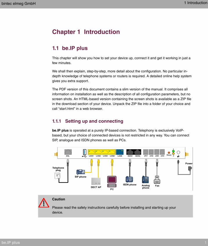
1.1.1 Setting up and connecting
be.IP plus is operated at a purely IP-based connection. Telephony is exclusively VoIP-
based, but your choice of connected devices is not restricted in any way. You can connect
SIP, analogue and ISDN phones as well as PCs.
Caution
Please read the safety instructions carefully before installing and starting up your
device.
bintec elmeg GmbH 1 Introduction
be.IP plus 1
Caution
Using an incorrect power supply unit may damage your device! You should only use
the power supply unit provided!
Set up and connect in the following sequence:
(1) Installation
When operational, be.IP plus needs to be wall-mounted in an upright position or
well ventilated inside of a device rack (please read chapter Mounting on page 14
carefully).
(2) Mains connection
Connect the network connection on the device with the power supply unit provided
to a 230 V mains socket.
(3) Antennas
Screw the standard antennas supplied on to the connectors provided for this pur-
pose
(4) DSL
Connect the DSL connector to the TAE plug using the grey cable.
(5) ISDN telephones
Connect an ISDN telephone at the internal ISDN connector of the be.IP plus .
(6) Analogue telephones
Connect your analogue terminals to the internal interfaces for analogue terminals
(a/b1 - a/b4). To do this, use the cable provided with the terminal.
(7) SIP telephones
Connect your SIP telephones to the 10/100/1000 Base-T Ethernet interfaces. In a
last step connect your PC and follow the instructions from the installation poster.
(8) PC
Connect a suitable PC to one of the Ethernet ports of be.IP plus using an Ethernet
cable. Should you run into any problems with the connection between your C and
your be.IP plus , read the corresponding sections on the basic configuration of your
device.
(9) VoIP
For a pure IP connection without ISDN refer to the instruction provided by your ser-
vice provider.
1 Introduction bintec elmeg GmbH
2 be.IP plus

1.1.2 Connectors
1 DSL interface Annex B/J
2 USB interface
3 10/100/1000 Base-T Ethernet interface (LAN 1 - LAN4)
4 Etherne WAN interface (LAN5)
5 Interface for ISDN telephones (ISDN1, ISDN2)
6 Internal interface for analogue telephones (a/b1 - a/b 4)
7 Socket for the power supply unit
1.1.3 Connections (on the side)
1 Antenna connector
2 Function key
3 Console
1.1.4 Mounting brackets
Due to the position of the devices in a rack it is recommended to use remote antenna. At-
tach the mounting brackets to the device using the supplied screws. The mounting brackets
and screws are available as an accessory (Part No. MN40285514).
bintec elmeg GmbH 1 Introduction
be.IP plus 3
Note
During operation in a rack the ambient temperature must not exceed 40 °C.
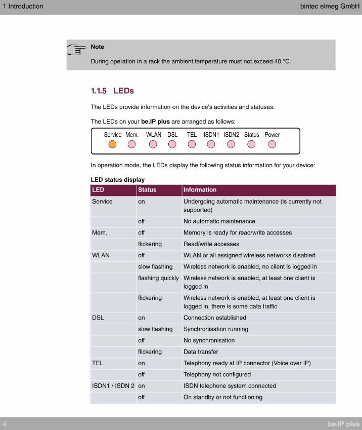
1.1.5 LEDs
The LEDs provide information on the device's activities and statuses.
The LEDs on your be.IP plus are arranged as follows:
In operation mode, the LEDs display the following status information for your device:
LED status display
LED Status Information
Service on Undergoing automatic maintenance (is currently not
supported)
off No automatic maintenance
Mem. off Memory is ready for read/write accesses
flickering Read/write accesses
WLAN off WLAN or all assigned wireless networks disabled
slow flashing Wireless network is enabled, no client is logged in
flashing quickly Wireless network is enabled, at least one client is
logged in
flickering Wireless network is enabled, at least one client is
logged in, there is some data traffic
DSL on Connection established
slow flashing Synchronisation running
off No synchronisation
flickering Data transfer
TEL on Telephony ready at IP connector (Voice over IP)
off Telephony not configured
ISDN1 / ISDN 2 on ISDN telephone system connected
off On standby or not functioning
1 Introduction bintec elmeg GmbH
4 be.IP plus

LED Status Information
Status onAfter switching on: Device is started
While operation: Fault
slow flashing The device is active
Power on The power supply is connected
off No power supply
The LEDs for the Ethernet sockets LAN 1-4 (LAN) and LAN5 (WAN) show the following
status information:
Ethernet-LEDs
LED Colour Status Information
LAN 1 to 4
(Link/Act)
Green on Ethernet connection established
LAN 1 to 4
(Link/Act)
Green flashing Data transmission via Ethernet
LAN 1 to 4
(Link/Act)
off No Ethernet connection
LAN 1 to 4 (Speed) Green on 1000 Mbit/s transfer rate
LAN 1 to 4 (Speed) Orange on 100 Mbit/s transfer rate
LAN 1 to 4 (Speed) off 10 Mbit/s transfer rate
LAN 5 (Link/Act) Green on WAN Ethernet connection established
LAN 5 (Link/Act) Green flashing Data transmission via ETH5t
LAN 5 (Link/Act) off No Ethernet connection
LAN 5 (Speed) Green on 1000 Mbit/s transfer rate
LAN 5 (Speed) Orange on 100 Mbit/s transfer rate
LAN 5 (Speed) off 10 Mbit/s transfer rate
LEDs back view
The LEDs are linked to those on the top of the device and show the identical behavior.
1 Status Green
bintec elmeg GmbH 1 Introduction
be.IP plus 5
2 Service Yellow (currently unsupported)
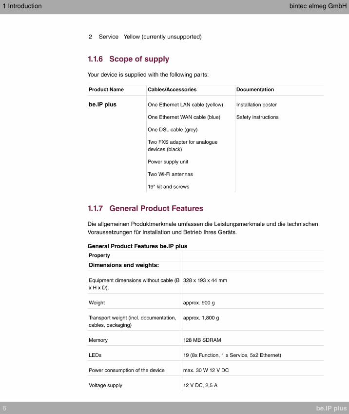
1.1.6 Scope of supply
Your device is supplied with the following parts:
Product Name Cables/Accessories Documentation
be.IP plus One Ethernet LAN cable (yellow)
One Ethernet WAN cable (blue)
One DSL cable (grey)
Two FXS adapter for analogue
devices (black)
Power supply unit
Two Wi-Fi antennas
19" kit and screws
Installation poster
Safety instructions
1.1.7 General Product Features
Die allgemeinen Produktmerkmale umfassen die Leistungsmerkmale und die technischen
Voraussetzungen für Installation und Betrieb Ihres Geräts.
General Product Features be.IP plus
Property
Dimensions and weights:
Equipment dimensions without cable (B
x H x D):
328 x 193 x 44 mm
Weight approx. 900 g
Transport weight (incl. documentation,
cables, packaging)
approx. 1,800 g
Memory 128 MB SDRAM
LEDs 19 (8x Function, 1 x Service, 5x2 Ethernet)
Power consumption of the device max. 30 W 12 V DC
Voltage supply 12 V DC, 2,5 A
1 Introduction bintec elmeg GmbH
6 be.IP plus

Property
Environmental requirements:
Storage temperature -20 °C to +70 °C
Operating temperature +5 °C to +40 °C
Relative atmospheric humidity max. 85%
Room classification Operate only in dry rooms
Available interfaces:
DSL interface Internal DSL modem
Ethernet IEEE 802.3 LAN (4-port
switch)
Permanently installed (twisted pair only), 10/100/1000 mbps,
autosensing, MDIX
ISDN interfaces 2 internal ISDN interfaces, ISDN termination
FXS 4 FXS interfaces (a/b1 - a/b4)
Serial interface V.24 Permanently installed, supports Baud rates: 1200 to 115200
Baud
Available sockets:
WLAN antennas R-SMA socket
Ethernet interfaces 1- 4 (LAN) RJ45 socket
Ethernet interface 5 (WAN) RJ45 socket
ISDN interface (ISDN1, ISDN2) RJ45 socket
FXS interface (a/b1 to a/b4) RJ12 socket
DSL interface RJ45 socket
Serial interface V.24 5-pole mini USB socket
USB USB connection type A
Barrel connector socket for power sup-
ply
1.2 Reset
The reset is performed by using the reset button at the terminal area.
bintec elmeg GmbH 1 Introduction
be.IP plus 7
The device is rebooted by quickly pressing the key (ca. one second). Pressing the key is
equivalent to an interruption of the power supply. Saved data are preserved, but all connec-
tions are interrupted.
If you press the reset key for approx. 30 seconds, the device performs a factory reset. Con-
nection data for incoming and for outgoing phone calls are preserved. The configuration is
deleted and all passwords are reset.
The reset has finished once the status LED flashes continuously again after approx. 30
seconds.
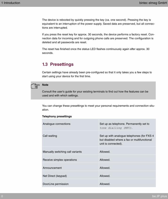
1.3 Presettings
Certain settings have already been pre-configured so that it only takes you a few steps to
start using your device for the first time.
Note
Consult the user's guide for your existing terminals to find out how the features can be
used and with which settings.
You can change these presettings to meet your personal requirements and connection situ-
ation.
Telephony presettings
Analogue connections Set up as telephone. Permanently set to
.
Call waiting Set up with analogue telephones (for FXS 4
but disabled where a fax or multifunctional
unit is connected).
Manually switching call variants Allowed.
Receive simplex operations Allowed.
Announcement Allowed.
Net Direct (keypad) Allowed.
DoorLine permission Allowed.
1 Introduction bintec elmeg GmbH
8 be.IP plus

TAPI Allowed.
Save connection data Set up.
Outside line Outside line via is set up.
International prefix Not set up.
Country code Not set up.
National prefix Not set up.
Area code Not set up.
Currency for billing Not set up.
Authorisation for the terminals Unrestricted authorisation.
Dir. call Not set up.
Own telephone number Is sent to the caller.
External calls Are signalled to all pre-configured internal
numbers ( ).
Call pickup Set up.
Internal telephone numbers For the ISDN (BRI) internal to the internal
ISDN bus, the internal telephone numbers
and are provided, for the analogue
connections FXS1 to FXS4 the internal tele-
phone numbers to are provided, and
for the system telephones the telephone
numbers and are provided, for DECT
systems the telephone number is
provided.
Pre-configured teams Internal number : Team All
Misdial routing To internal number (Team All)
Team call forwarding Allowed.
bintec elmeg GmbH 1 Introduction
be.IP plus 9
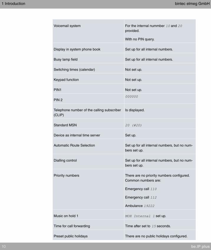
Voicemail system For the internal nummber and
provided.
With no PIN query.
Display in system phone book Set up for all internal numbers.
Busy lamp field Set up for all internal numbers.
Switching times (calendar) Not set up.
Keypad function Not set up.
PIN1 Not set up.
PIN 2
Telephone number of the calling subscriber
(CLIP)
Is displayed.
Standard MSN
Device as internal time server Set up.
Automatic Route Selection Set up for all internal numbers, but no num-
bers set up.
Dialling control Set up for all internal numbers, but no num-
bers set up.
Priority numbers There are no priority numbers configured.
Common numbers are:
Emergency call
Emergency call
Ambulance
Music on hold 1 set up.
Time for call forwarding Time after set to seconds.
Preset public holidays There are no public holidays configured.
1 Introduction bintec elmeg GmbH
10 be.IP plus
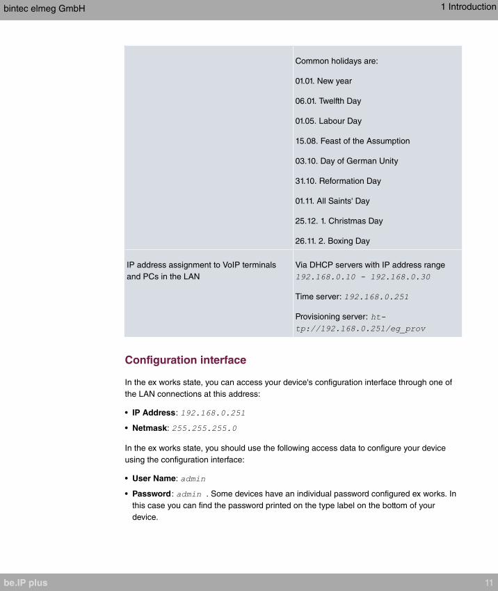
Common holidays are:
01.01. New year
06.01. Twelfth Day
01.05. Labour Day
15.08. Feast of the Assumption
03.10. Day of German Unity
31.10. Reformation Day
01.11. All Saints' Day
25.12. 1. Christmas Day
26.11. 2. Boxing Day
IP address assignment to VoIP terminals
and PCs in the LAN
Via DHCP servers with IP address range
Time server:
Provisioning server:
Configuration interface
In the ex works state, you can access your device's configuration interface through one of
the LAN connections at this address:
• IP Address:
• Netmask:
In the ex works state, you should use the following access data to configure your device
using the configuration interface:
• User Name:
• Password : . Some devices have an individual password configured ex works. In
this case you can find the password printed on the type label on the bottom of your
device.
bintec elmeg GmbH 1 Introduction
be.IP plus 11
Note
After you log into the device for the first time, you will be prompted to enter a secure
password. When you do this, please note the guidance that is displayed on secure
passwords! When the configuration procedure is complete, select the Save configura-
tion button! Otherwise the new, secure password will be lost when there is a restart.
Select operating mode
be.IP plus allows you to switch between the operation modes of a PABX and that of a me-
dia gateway.
Note
After switching to the media gateway operation mode you can find an adequate docu-
mentation of the software in the manual of the be.IP.
You can change the operating mode in the menu Assistants+First Steps->Operating
Mode. Note that some features will not then be available. Assembly and the basic configur-
ation are exactly the same.
When the operating mode is changed, the device is restarted. Settings made in the current
operating mode are backed up and reloaded on return to the current operating mode, so
you do not have to completely rebuild the configuration. If you change the operating mode
for the first time, the current configuration is converted once to a configuration of the new
operating mode. It can happen that not all settings are completely adopted, so check the
new configuration for completeness after the change. Thereafter, the configurations for op-
eration as a telephone system and as a media gateway are stored separately from each
other and changes in one mode are not adopted in the configuration of the other mode.
Provider selection
After the first login to the web interface you are given the option to choose your Internet
provider.
If you want to configure a connection provided by Deutschen Telekom, follow the steps of
the Initial operation Telekom menu. Clicking Apply takes you through the individual steps
(see also the installation poster section First time use with the initial operation menu).
If you want to configure a connection offered by a different provider, you are taken to User
view of the status page of your device. If you click on one of the buttons, you are taken
to the corresponding configuration assistent.
1 Introduction bintec elmeg GmbH
12 be.IP plus

1.4 Support-Information
If you have any questions about your new product, please contact a local, certified retailer
for prompt technical support. Resellers have been trained by us and receive privileged sup-
port.
Further information on our support and service offers can be found on our web site at
www.bintec-elmeg.com .
bintec elmeg GmbH 1 Introduction
be.IP plus 13
Chapter 2 Mounting
Warning
To avoid electric shocks, please take care when connecting telecommunications net-
works (TNV electric circuits). LAN ports also use RJ connectors.
Caution
To ensure that the be.IP plus can operate free of faults, it must be mounted upright on
a wall or well ventilated inside of a device rack. The device should not be exposed to
direct sunlight or other sources of heat. Please note, too, the gaps that you need to
comply with (see Wall mounting on page 15).
2.1 Connecting terminals
2.1.1 Internal ISDN connection
The internal ISDN connection on the be.IP plus gives each internal ISDN connection a 2.5
watt power supply for connecting a maximum of two unpowered ISDN terminals. In its ex
works state, the internal ISDN connection is set up as a "short passive bus" ("S0 bus"). It is
the simple bus cabling in an ISDN system with a length of up to 120 m.
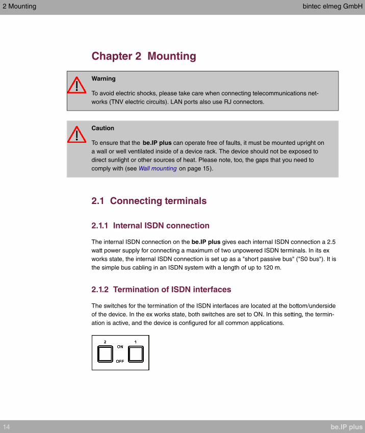
2.1.2 Termination of ISDN interfaces
The switches for the termination of the ISDN interfaces are located at the bottom/underside
of the device. In the ex works state, both switches are set to ON. In this setting, the termin-
ation is active, and the device is configured for all common applications.
2 Mounting bintec elmeg GmbH
14 be.IP plus
2.2 Reset button
The reset button which allows you to restart the device or to reset it to the ex works state is
located at the terminal area (cf. Reset on page 7).
2.3 Wall mounting
The various assembly processes are described in this section. Please comply with these
processes.
(1) Find an installation site which is a maximum of 1.5 metres away from a 230 V mains
socket and 2.5 metres from the network operator's transfer point.
(2) To prevent devices interfering with each other, do not install the device close to elec-
tronic devices such as hi-fi systems, office equipment or microwave ovens. Neither
should you install it near heat sources such as radiators, or in damp rooms.
(3) Comply with the gaps as indicated at the bottom in the picture.
(4) Mark the drilling holes in the wall.
(5) Check that all the points where the be.IP plus is attached to the wall can bear its
weight. Ensure that there are no utility lines, cables etc located in the area where the
holes are marked.
(6) Drill the holes at the points marked (if inserting into rawlplugs, use a 5 mm masonry
drill). Insert the rawlplug.
(7) Screw the top two screws in in such a way that there is still a gap of about 5 mm
between the screw head and the wall.
(8) Hang the be.IP plus with the rear brackets from above behind the screw heads.
(9) If necessary, install the sockets for the terminals. Connect the socket installation to
that of the device. The sockets are used for a permanent installation, for example in a
hallway. When they are installed, the connecting cables are connected to the connect-
ors on the device,
(10) Plug the connectors on the device into the sockets.
(11) Connect the be.IP plus to the external connections. To do this, you can follow the in-
structions given on the installation poster provided.
(12) Plug the power supply unit into the 230 V socket.
(13) Plug the barrel connector on the power supply unit into the corresponding socket on
your device.
(14) Now you are ready to use the device.
bintec elmeg GmbH 2 Mounting
be.IP plus 15

2.4 Pin Assignments
2.4.1 Ethernet interfaces
The devices feature an Ethernet interface with integrated 4 port switch (ETH1 - ETH4).
The 4-port switch is used to connect individual PCs or other switches. The connection oc-
curs via RJ45 sockets.
The pin assignment for the Ethernet 10/100/1000 Base-T interface (RJ45 connector) is as
follows:
RJ45 socket for Ethernet connection
Pin Function
1 Pair 0 +
2 Pair 0 -
3 Pair 1 +
4 Pair 2 +
5 Pair 2 -
6 Pair 1 -
7 Pair 3 +
8 Pair 3 -
2.4.2 ISDN interface
The connection is made via an RJ45 socket:
2 Mounting bintec elmeg GmbH
16 be.IP plus
The pin assignment for the ISDN interface (RJ45 socket) is as follows:
RJ45 socket for ISDN connection
Pin Function (NT)
1 Not used
2 Not used
3 Receive (+) 2a
4 Transmit (+) 1a
5 Transmit (-) 1b
6 Receive (-) 2b
7 Not used
8 Not used
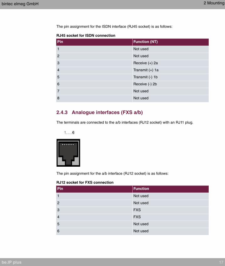
2.4.3 Analogue interfaces (FXS a/b)
The terminals are connected to the a/b interfaces (RJ12 socket) with an RJ11 plug.
The pin assignment for the a/b interface (RJ12 socket) is as follows:
RJ12 socket for FXS connection
Pin Function
1 Not used
2 Not used
3 FXS
4 FXS
5 Not used
6 Not used
bintec elmeg GmbH 2 Mounting
be.IP plus 17
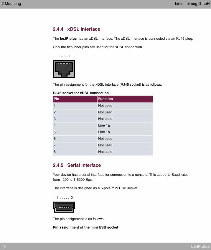
2.4.4 xDSL interface
The be.IP plus has an xDSL interface. The xDSL interface is connected via an RJ45 plug.
Only the two inner pins are used for the xDSL connection.
The pin assignment for the xDSL interface (RJ45 socket) is as follows:
RJ45 socket for xDSL connection
Pin Function
1 Not used
2 Not used
3 Not used
4 Line 1a
5 Line 1b
6 Not used
7 Not used
8 Not used
2.4.5 Serial interface
Your device has a serial interface for connection to a console. This supports Baud rates
from 1200 to 115200 Bps.
The interface is designed as a 5-pole mini USB socket.
The pin assignment is as follows:
Pin assignment of the mini USB socket
2 Mounting bintec elmeg GmbH
18 be.IP plus
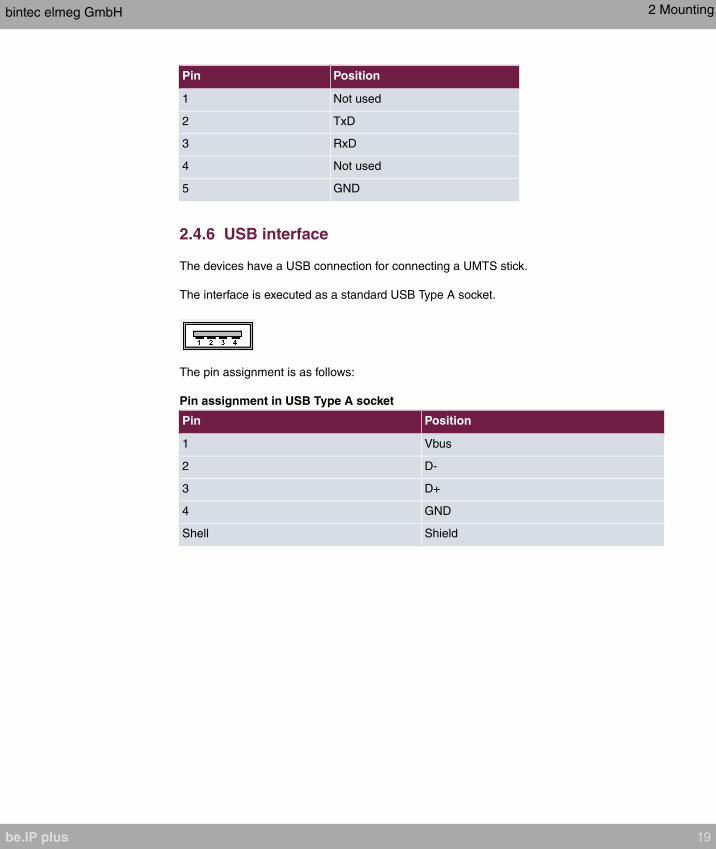
Pin Position
1 Not used
2 TxD
3 RxD
4 Not used
5 GND
2.4.6 USB interface
The devices have a USB connection for connecting a UMTS stick.
The interface is executed as a standard USB Type A socket.
The pin assignment is as follows:
Pin assignment in USB Type A socket
Pin Position
1 Vbus
2 D-
3 D+
4 GND
Shell Shield
bintec elmeg GmbH 2 Mounting
be.IP plus 19

Chapter 3 Basic configuration
The way to obtain the basic configuration is explained below step-by-step. A detailed online
help system gives you extra support.
3.1 Preparations
Your device is factory configured as a DHCP server so that it can provide PCs on your LAN
that have no IP configuration with all the information required for a connection. How you set
up the PC that you want to do the basic configuration on so that it automatically gets an IP
configuration is described in Setting up a PC on page 22.
Note
If you already run a DHCP server on your LAN, it is recommended that you connect
only a single PC to your be.IP plus so that a separate network is created.
3.1.1 Systemsoftware
Your device contains the version of the system software available at the time of production.
More recent versions may have since been released.
You can easily update it using the configuration interface in the Maintenance->Software
&Configuration menu. For a description of the procedure, see Software updates for be.IP
plus on page 26.
3.1.2 System requirements
To configure the device, your PC must meet the following system requirements:
• Suitable operating system (Windows, Linux, MAC OS)
• A web browser (Internet Explorer, Firefox, Chrome) in the current version
• Installed network card (Ethernet)
• Installed TCP/IP protocol
• High colour display to show the graphics correctly
3 Basic configuration bintec elmeg GmbH
20 be.IP plus

3.1.3 Gathering data
You will quickly collect the main data for doing the configuration with the configuration inter-
face.
Before you start the configuration, you should gather the data for the following purposes:
• Network settings (only if you intend to integrate your device into an existing network infra-
structure)
• SIP provider
• Internet access
The following table shows examples of possible values for the necessary access data. You
can enter your personal data in the "Your values" column, so that you can refer to these
values later when needed.
Basic configuration
For a basic configuration of your device, you need information that relates to your network
environment:
Network settings
Access data Example value Your values
IP address of your gateway
Netmask of your gateway
SIP provider
Access data Example value Your values
Description Enter the name of your
SIP provider, e.g.
.
Authentication ID Enter you ID, e.g. your
Email Address
Password Enter your password that
you received from your
SIP provider.
Registrar Enter the appropriate re-
bintec elmeg GmbH 3 Basic configuration
be.IP plus 21

Access data Example value Your values
gistrar, e. g.
.
Call numbere. g.
Data for internet access over xDSL
Access data Example value Your values
Provider name
Protocol
Encapsulation
VPI (Virtual Path Identifier)
VCI (Virtual Circuit Identifier)
Connection ID (12-digit)
T-Online number (usually 12 digits)
Joint user account
Password
3.1.4 Setting up a PC
To access your device via the network and to be able to do a configuration using the con-
figuration interface, the PC used for the configuration has to satisfy some prerequisites.
• Make sure that the TCP/IP protocol is installed on the PC.
Checking the TCP/IP protocol
Proceed as follows to check whether you have the protocol installed:
(1) Click the Windows Start button and then Settings -> Control Panel -> Network Con-
nections (Windows XP) or Control Panel -> Network and Sharing Center->
Change Adapter Settings (Windows 7).
3 Basic configuration bintec elmeg GmbH
22 be.IP plus
(2) Click on LAN Connection.
(3) Click on Properties in the status window.
(4) Look for the Internet Protocol (TCP/IP) entry in the list of network components.
Installing the TCP/IP protocol
If you cannot find the Internet Protocol (TCP/IP) entry, install the TCP/IP protocol as fol-
lows:
(1) First click Properties, then Install in the status window of the LAN Connection.
(2) Select the Protocol entry.
(3) Click Add.
(4) Select Internet Protocol (TCP/IP) and click on OK.
(5) Follow the on-screen instructions and restart your PC when you have finished.
Configuring a Windows PC as a DHCP client
Assign an IP address to your PC as follows:
(1) Initially, proceed as described to display the network properties.
(2) Select Internet Protocol (TCP/IP) and click on Properties.
(3) Choose Determine IP address automatically .
(4) Also choose Determine DNS server address automatically .
(5) Close all the windows by selecting OK.
Your PC should now meet all the prerequisites for configuring your device.
Note
You can now launch the configuration interface for doing the configuration by entering
the preconfigured IP address of your device (192.168.0.251) in a supported browser
(Internet Explorer 6 or later, Mozilla Firefox 1.2 or later) and entering the pre-set login
data (User: , Password : ).
3.2 Configuring the system
bintec elmeg GmbH 3 Basic configuration
be.IP plus 23

3.2.1 Network setting (LAN)
If you intend to integrate your device into an existing network infrastructure, select the As-
sistants->First steps->Basic Settings menu for the network settings. For the LAN IP con-
figuration, the Address Mode is set to Static by default, since your system is delivered ex
works with a fixed IP. Enter the necessary IP Address for your device in your LAN and the
associated Netmask. Leave all the other settings and click OK. Save the configuration by
clicking on the Save Configuration button above the menu navigation.
3.2.2 Enter SIP provider
As an option, you may enter SIP providers for external telephone connections. Please note
the description in the online help for the menu VoIP->Settings->SIP Provider->New.
3.3 Setting up an internet connection
You can establish an Internet connection with your device.
3.3.1 Internet connection via the internal VDSL modem
To make it easier to configure an VDSL internet connection, the configuration interface has
a wizard to guide you through the connection set-up process simply and quickly.
(1) In the user interface, go to the Assistants->Internet menu.
(2) Use New to create a new entry, and copy the Connection Type
.
(3) Follow the steps shown by the wizard. The wizard has its own online help, which of-
fers all of the information you may require.
(4) Once you have exited the wizard, save the configuration by clicking on the Save con-
figuration button above the menu navigation.
3.3.2 Other internet connections
In addition to an VDSL connection over the internal VDSL modem, you can connect your
device to the internet with other types of connection or via an external modem. The Inter-
net wizard in the configuration interface provides support with configurations of this type.
3 Basic configuration bintec elmeg GmbH
24 be.IP plus

3.3.3 Testing the configuration
Once you have finished configuring your device, you can test the connection in your LAN
and to the Internet.
Carry out the following steps to test your device:
(1) Test the connection from any device in the local network to your device. In the Win-
dows Start menu, click Run and enter followed by a space and then the IP ad-
dress of your device (e.g. ). A window appears with the message
.
(2) Test the Internet access by entering www.bintec-elmeg.com in the Internet browser.
Note
Incorrectly configured terminals may lead to unwanted connections and higher
charges! Monitor your device and make sure it only sets up connections at the times
you want it to. Watch the light indicators on your device (indicators for ISDN, DSL and
the Ethernet interfaces).
3.4 User access
Those who administer and set up the system can set up a personalised configuration ac-
cess for the users. This will enable the users to view their main personal settings and cus-
tomise some of them.
Note
Those who administer and set up the system can access the settings and data of all
the users. It is only the personal telephone book (User Phonebook) which the user
can set up for themselves which can only be managed and viewed with the personal
user login data.
To log into the configuration interface with the access data you have been assigned, enter
your user name and your password in the login window.
The administrator configures the user accesses in the Numbering->User Settings->Users
menu.
Users can also find help with the available configuration options in the online help system.
bintec elmeg GmbH 3 Basic configuration
be.IP plus 25
3.5 Software updates for be.IP plus
The range of functions in the be.IP plus is continuously being extended. For new software
versions can be carried out easily with the GUI.
A functional Internet connection is required for any kind of an automatic update.
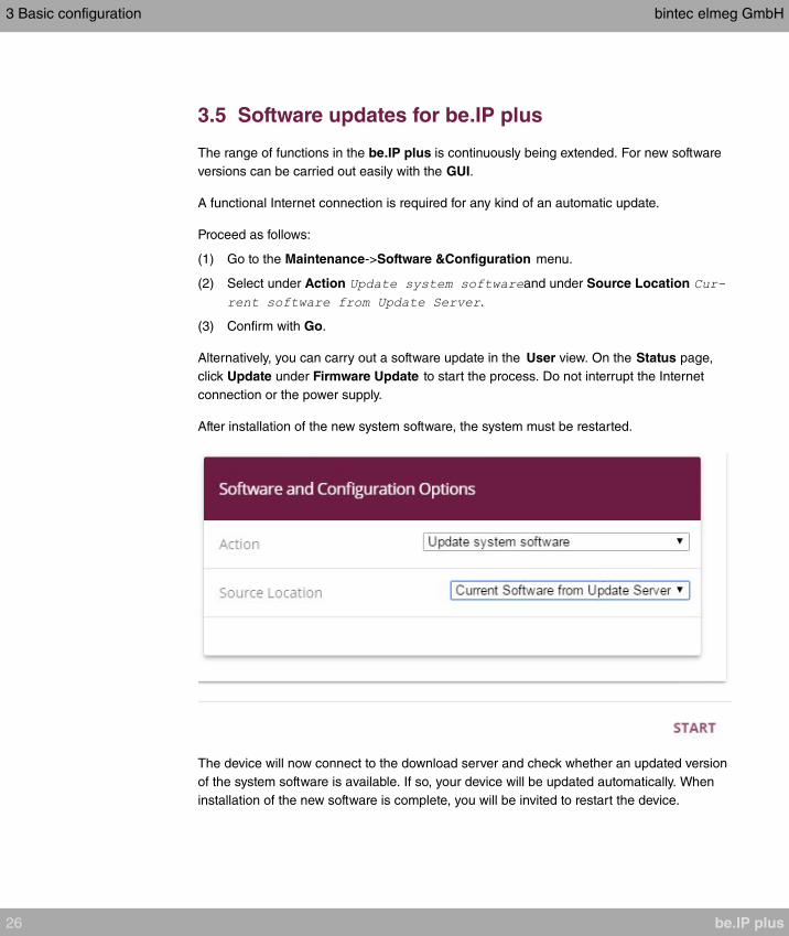
Proceed as follows:
(1) Go to the Maintenance->Software &Configuration menu.
(2) Select under Action and under Source Location
.
(3) Confirm with Go.
Alternatively, you can carry out a software update in the User view. On the Status page,
click Update under Firmware Update to start the process. Do not interrupt the Internet
connection or the power supply.
After installation of the new system software, the system must be restarted.
The device will now connect to the download server and check whether an updated version
of the system software is available. If so, your device will be updated automatically. When
installation of the new software is complete, you will be invited to restart the device.
3 Basic configuration bintec elmeg GmbH
26 be.IP plus
Caution
Once you have clicked on Go the update cannot be cancelled/interrupted. If an error
occurs during the update, do not re-start the device and contact support.
bintec elmeg GmbH 3 Basic configuration
be.IP plus 27
Chapter 4 Operation via the telephone
The operation and configuration of the system via a connected telephone is described in
two separate documents. You will find the document as download under ht-
tp://bintec-elmeg.com
4 Operation via the telephone bintec elmeg GmbH
28 be.IP plus

Chapter 5 Access and configuration
5.1 Access via LAN
Access via one of your device's Ethernet interfaces allows you to open the configuration in-
terface in a web browser.
5.1.1 HTTP/HTTPS
With a current web browser, you can use the HTML interface to configure your device. For
this, enter the following in your web browser's address field
•
or
5.2 Configuration
The configuration is done using the HTML configuration interface.
5.2.1 Configuration interface
The configuration interface is a web-based graphic user surface that you can use from any
PC with an up-to-date Web browser via an HTTP or HTTPS connection.
With the configuration interface you can perform all the configuration tasks easily and con-
veniently. It is integrated in your device and is available in English.
The settings you make are applied with the OK or Apply button in the relevant menu, and
you do not have to restart the device.
If you finish the configuration and want to save your settings so that they are loaded as the
boot configuration when you reboot your device, save these by clicking the Save configur-
ation button.
You can also use the configuration interface to monitor the most important function para-
meters of your device.
bintec elmeg GmbH 5 Access and configuration
be.IP plus 29
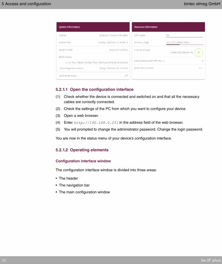
5.2.1.1 Open the configuration interface
(1) Check whether the device is connected and switched on and that all the necessary
cables are correctly connected.
(2) Check the settings of the PC from which you want to configure your device.
(3) Open a web browser.
(4) Enter in the address field of the web browser.
(5) You will prompted to change the administrator password. Change the login password.
You are now in the status menu of your device's configuration interface.
5.2.1.2 Operating elements
Configuration interface window
The configuration interface window is divided into three areas:
• The header
• The navigation bar
• The main configuration window
5 Access and configuration bintec elmeg GmbH
30 be.IP plus
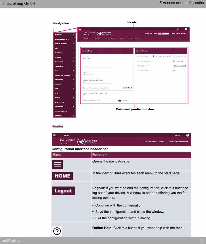
Header
Configuration interface header bar
Menu Function
Opens the navigation bar.
In the view of User executes each menu to the start page.
Logout: If you want to end the configuration, click this button to
log out of your device. A window is opened offering you the fol-
lowing options:
• Continue with the configuration,
• Save the configuration and close the window,
• Exit the configuration without saving.
Online Help: Click this button if you want help with the menu
bintec elmeg GmbH 5 Access and configuration
be.IP plus 31

Menu Function
now active. The description of the sub-menu where you are now
is displayed.
Language: From the dropdown menu, select the language in
which the configuration interface is to be displayed. Here, you
can select the language in which you want to carry out the con-
figuration. and are available.
View: Select the desired view from the dropdown menu.
, and can be selected. Also the Initial
operation can be start again from here.
Save configuration button.
If you click the Save configuration button, you will be asked
"Do you really want to save the current configuration as a boot
configuration?"
You can
• Save configuration
• Save configuration with boot backup
Navigation bar
5 Access and configuration bintec elmeg GmbH
32 be.IP plus
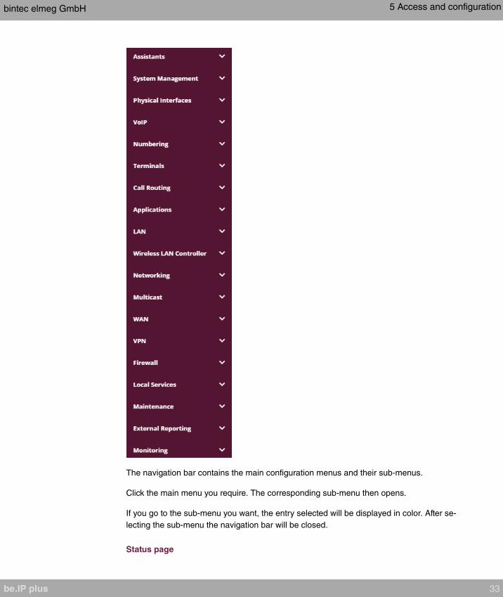
The navigation bar contains the main configuration menus and their sub-menus.
Click the main menu you require. The corresponding sub-menu then opens.
If you go to the sub-menu you want, the entry selected will be displayed in color. After se-
lecting the sub-menu the navigation bar will be closed.
Status page
bintec elmeg GmbH 5 Access and configuration
be.IP plus 33

If you open the configuration interface the status page of your device is displayed after you
log in. The most important data of your device can be seen on this at a glance.
Main configuration window
The sub-menus generally contain several pages. These are called using the buttons at the
top of the main window. If you click a button, the window is opened with the basic paramet-
ers. You can extend this by clicking the Advanced Settings tab, which displays the addi-
tional options.
Configuration elements
The various actions that you can perform when configuring your device in the configuration
interface are triggered by means of the following buttons:
Buttons
Button Function
Updates the view.
If you do not want to save a newly configured list entry, cancel
this and any settings made by pressing Cancel.
Confirms the settings of a new entry and the parameter
changes in a list.
Immediately starts the configured action.
Calls the sub-menu to create a new entry.
Inserts an entry in an internal list.
Symbols
Icon Function
Deletes the list entry.
Displays the menu for changing the settings of an entry.
Displays the details for an entry.
Voicemail message can be intercepted.
5 Access and configuration bintec elmeg GmbH
34 be.IP plus

Icon Function
Messages will be saved.
Select the button to go to the elmeg IP1x0 telephone user inter-
face administrator page.
Moves an entry. A combo box opens in which you can choose
the list entry that selected entry is to be placed in front of/after.
Creates another list entry first and opens the configuration
menu.
Sets the status of the entry to .
Sets the status of the entry to .
Indicates "Dormant" status for an interface or connection.
Indicates "Up" status for an interface or connection.
Indicates "Down" status for an interface or connection.
Indicates "Blocked" status for an interface or connection.
Indicates that data traffic is encrypted.
Triggers a WLAN bandscan.
Displays the next page in a list.
Displays the previous page in a list.
List options
Menu Function
Update Interval Here you can set the interval in which the view is to be updated.
To do this, enter a period in seconds in the input field and con-
firm it with .
bintec elmeg GmbH 5 Access and configuration
be.IP plus 35

Menu Function
Filter You can have the list entries filtered and displayed according to
certain criteria.
You can determine the number of entries displayed per page by
entering the required number in Viewxper page.
Use the and buttons to scroll one page forward and one
page back.
You can filter according to certain keywords within the configur-
ation parameters by selecting the filter rule you want under Fil-
ter inx <Option> y and entering the search word in the input
field. launches filter operation.
Configuration elements Some lists contain configuration elements.
You can therefore change the configuration of the correspond-
ing list entry directly in the list.
Configuration of the update interval
Filter list
On the status page you can open the option Automatic Refresh Interval using the button
.
5 Access and configuration bintec elmeg GmbH
36 be.IP plus
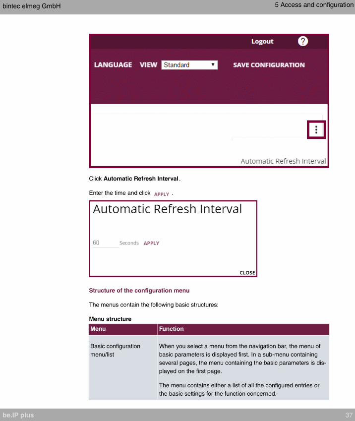
Click Automatic Refresh Interval .
Enter the time and click .
Structure of the configuration menu
The menus contain the following basic structures:
Menu structure
Menu Function
Basic configuration
menu/list
When you select a menu from the navigation bar, the menu of
basic parameters is displayed first. In a sub-menu containing
several pages, the menu containing the basic parameters is dis-
played on the first page.
The menu contains either a list of all the configured entries or
the basic settings for the function concerned.
bintec elmeg GmbH 5 Access and configuration
be.IP plus 37
Menu Function
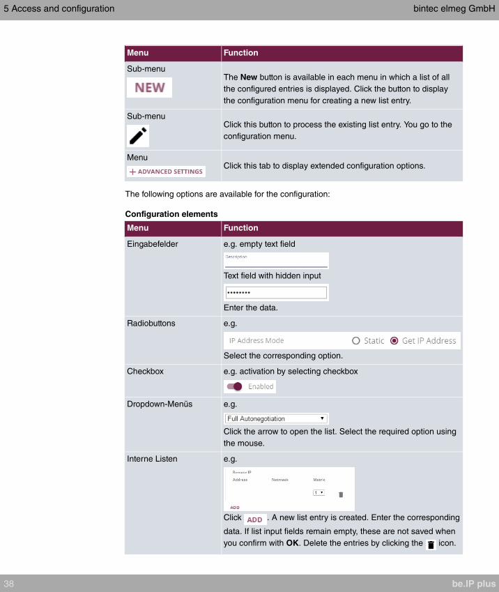
Sub-menuThe New button is available in each menu in which a list of all
the configured entries is displayed. Click the button to display
the configuration menu for creating a new list entry.
Sub-menuClick this button to process the existing list entry. You go to the
configuration menu.
MenuClick this tab to display extended configuration options.
The following options are available for the configuration:
Configuration elements
Menu Function
Eingabefelder e.g. empty text field
Text field with hidden input
Enter the data.
Radiobuttons e.g.
Select the corresponding option.
Checkbox e.g. activation by selecting checkbox
Dropdown-Menüs e.g.
Click the arrow to open the list. Select the required option using
the mouse.
Interne Listen e.g.
Click . A new list entry is created. Enter the corresponding
data. If list input fields remain empty, these are not saved when
you confirm with OK. Delete the entries by clicking the icon.
5 Access and configuration bintec elmeg GmbH
38 be.IP plus
Display of options that are not available
Options that are not available because they depend on the selection of other options are
generally hidden. If the display of these options could be helpful for a configuration de-
cision, they are instead greyed out and cannot be selected.
Important
Please look at the messages displayed in the sub-menus. These provide information
on any incorrect configurations.
5.2.1.3 Menus
The configuration options of your device are contained in the sub-menus, which are dis-
played in the navigation bar in the left-hand part of the window.
Note
Please note that not all devices have the full range of functions. Use your product spe-
cification to check which software your device has.
bintec elmeg GmbH 5 Access and configuration
be.IP plus 39

Chapter 6 Assistants
The Assistants menu offers step-by-step instructions for the following basic configuration
tasks:
• Initial operation Telekom
• First steps
• Internet
• WLAN
• Telephony
• VPN
Choose the corresponding task from the navigation bar and follow the instructions and ex-
planations on the separate pages of the Wizard.
6 Assistants bintec elmeg GmbH
40 be.IP plus

Chapter 7 System Management
The System Management menu contains general system information and settings.
You see a system status overview. Global system parameters such as the system name,
date/time, passwords and licences are managed and the access and authentication meth-
ods are configured.
7.1 Status
If you log into the GUI, your device displays the status page in the Users view.
Here you can find links to the configuration assistants that will support you with an easy
configuration of the most important settings.
Moreover, you can carry out a Firmware Update . Click Update to start the process.
Note
Do not interrupt the Internet connection or the power supply.
After installation of the new system software, the system must be restarted.
In the Full Access and Expert views of your device, the status page displays the most
important system information.
You see an overview of the following data:
• System status
• Your device's activities: Resource utilisation, active sessions and tunnels
• Status and basic configuration of the LAN, WAN, ISDN, and ADSL interfaces
• Information on plugged add-on modules (if any)
Note
The information displayed depends on the layout and the operation mode of your
device.
You can customise the update interval of the status page by entering the desired period in
seconds as Automatic Refresh Interval and clicking on the Apply button.
bintec elmeg GmbH 7 System Management
be.IP plus 41
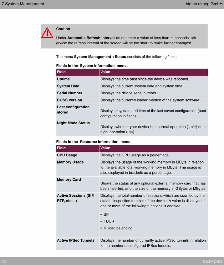
Caution
Under Automatic Refresh Interval do not enter a value of less than seconds, oth-
erwise the refresh interval of the screen will be too short to make further changes!
The menu System Management->Status consists of the following fields:
Fields in the System Information menu.
Field Value
Uptime Displays the time past since the device was rebooted.
System Date Displays the current system date and system time.
Serial Number Displays the device serial number.
BOSS Version Displays the currently loaded version of the system software.
Last configuration
stored Displays day, date and time of the last saved configuration (boot
configuration in flash).
Night Mode StatusDisplays whether your device is in normal operation ( ) or in
night operation ( ).
Fields in the Resource Information menu.
Field Value
CPU Usage Displays the CPU usage as a percentage.
Memory Usage Displays the usage of the working memory in MByte in relation
to the available total working memory in MByte. The usage is
also displayed in brackets as a percentage.
Memory CardShows the status of any optional external memory card that has
been inserted, and the size of the memory in GBytes or MBytes.
Active Sessions (SIF,
RTP, etc... )
Displays the total number of sessions which are counted by the
stateful inspection function of the device. A value is displayed if
one or more of the following functions is enabled:
• SIF
• TDCR
• IP load balancing
.
Active IPSec Tunnels Displays the number of currently active IPSec tunnels in relation
to the number of configured IPSec tunnels.
7 System Management bintec elmeg GmbH
42 be.IP plus
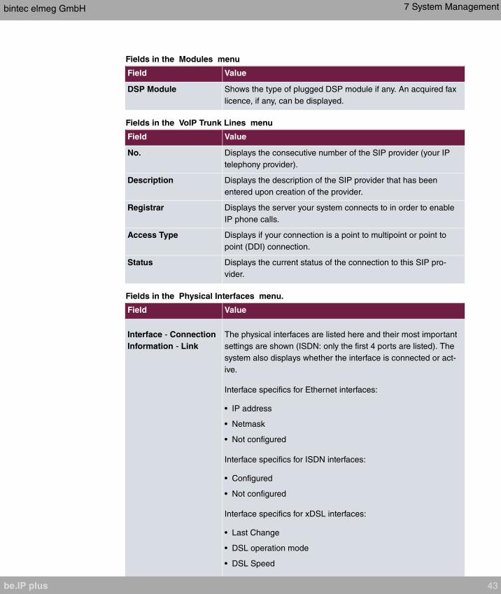
Fields in the Modules menu
Field Value
DSP Module Shows the type of plugged DSP module if any. An acquired fax
licence, if any, can be displayed.
Fields in the VoIP Trunk Lines menu
Field Value
No. Displays the consecutive number of the SIP provider (your IP
telephony provider).
Description Displays the description of the SIP provider that has been
entered upon creation of the provider.
Registrar Displays the server your system connects to in order to enable
IP phone calls.
Access Type Displays if your connection is a point to multipoint or point to
point (DDI) connection.
Status Displays the current status of the connection to this SIP pro-
vider.
Fields in the Physical Interfaces menu.
Field Value
Interface - Connection
Information - Link
The physical interfaces are listed here and their most important
settings are shown (ISDN: only the first 4 ports are listed). The
system also displays whether the interface is connected or act-
ive.
Interface specifics for Ethernet interfaces:
• IP address
• Netmask
• Not configured
Interface specifics for ISDN interfaces:
• Configured
• Not configured
Interface specifics for xDSL interfaces:
• Last Change
• DSL operation mode
• DSL Speed
bintec elmeg GmbH 7 System Management
be.IP plus 43
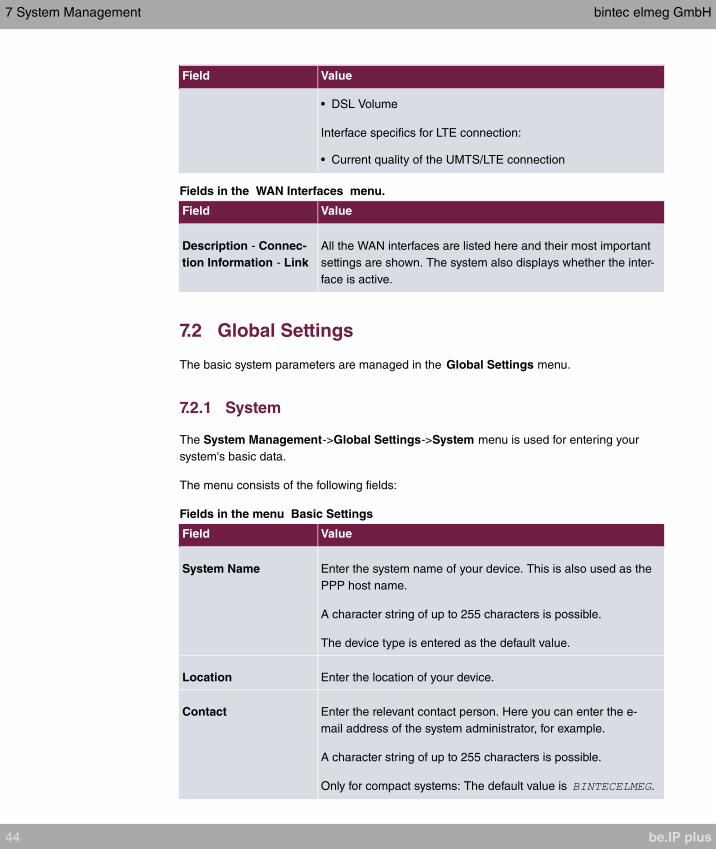
Field Value
• DSL Volume
Interface specifics for LTE connection:
• Current quality of the UMTS/LTE connection
Fields in the WAN Interfaces menu.
Field Value
Description - Connec-
tion Information - Link
All the WAN interfaces are listed here and their most important
settings are shown. The system also displays whether the inter-
face is active.
7.2 Global Settings
The basic system parameters are managed in the Global Settings menu.
7.2.1 System
The System Management->Global Settings->System menu is used for entering your
system's basic data.
The menu consists of the following fields:
Fields in the menu Basic Settings
Field Value
System Name Enter the system name of your device. This is also used as the
PPP host name.
A character string of up to 255 characters is possible.
The device type is entered as the default value.
Location Enter the location of your device.
Contact Enter the relevant contact person. Here you can enter the e-
mail address of the system administrator, for example.
A character string of up to 255 characters is possible.
Only for compact systems: The default value is .
7 System Management bintec elmeg GmbH
44 be.IP plus

Field Value
Maximum Number of
Syslog Entries
Enter the maximum number of syslog messages that are stored
internally in the device.
Possible values are to .
The default value is . You can display the stored messages in
Monitoring->Internal Log.
Maximum Message
Level of Syslog Entries
Select the priority of system messages above which a log
should be created.
System messages are only recorded internally if they have a
higher or identical priority to that indicated, i.e. all messages
generated are recorded at syslog level .
Possible values:
• : Only messages with emergency priority are re-
corded.
• : Messages with emergency and alert priority are recor-
ded.
• : Messages with emergency, alert and critical prior-
ity are recorded.
• : Messages with emergency, alert, critical and error pri-
ority are recorded.
• : Messages with emergency, alert, critical, error and
warning priority are recorded.
• : Messages with emergency, alert, critical, error,
warning and notice priority are recorded.
• (default value): Messages with emergency,
alert, critical, error, warning, notice and information priority are
recorded.
• : All messages are recorded.
Maximum Number of
Accounting Log
Entries
Enter the maximum number of login process entries that are
stored internally in the device.
Possible values are to .
The default value is
Show Manufacturer Here you can determine if the manufacturer part of a MAC ad-
bintec elmeg GmbH 7 System Management
be.IP plus 45

Field Value
Names dress is to be "translated". The manufacturer part takes up to
eight characters at the beginning of the MAC address. Instead
of, e.g., , is dis-
played if this option is enabled.
Autosave Configura-
tion
Here you can choose whether configuration changes are auto-
matically saved.
The option is enabled per default.
You can find a detailed description of this function below.
Autosave Configuration
Whenever you make a change to the current configuration using the GUI, this change be-
comes immediately active once you confirm the change (e.g. with the OK button). Addition-
ally, the status of the configuration is stored, the syslog (syslogl evel = ) shows
. As soon as this state has been reached, and the next bit of
HTTP(S) traffic between the browser and the GUI is registered, the change is confirmed
and cleared for saving. The syslog shows .
As soon as this state has been reached and the configuration session via the browser is
terminated without the user actively saving the new configuration, your device automatically
saves the new configuration once the HTTP(S) session has timed out. The syslog first in-
forms about the termination of the active session (e.g.
), and
then confirms the configuration .
In case a configuration error has locked you out of the GUI, the implicit confirmation of the
change ( ) does not take place, and it is not saved
after session termination. A reboot of your device then resets the change.
Transfer to busy subscriber
In configuration, you can define whether transfer of a call to an engaged subscriber is pos-
sible, or whether the caller hears the busy tone on Off and the call is thus ended. Other-
wise, the caller remains on hold and hears the music-on-hold. If the target subscriber
hangs up, the subscriber on hold hears the ringing tone if has been
selected, or Music on Hold if has been selected until the target
subscriber accepts the call. The target subscriber is called and can take the call on hold.
Fields in the menu System Settings
7 System Management bintec elmeg GmbH
46 be.IP plus

Field Value
Transfer Signalling Set how the connecting to an internal subscriber shut be man-
aged.
Possible values:
• (default value): While being trans-
ferred, the caller hears music on hold from the system; after
being transferred, the ringing tone.
• : The caller hears the system's on-
hold music until the targte subscriber accepts the call.
Transfer to busy exten-
sion
Set whether a caller may be transferred to a busy subscriber.
The function is activated with .
The function is disabled by default.
Rerouting to Number Set the destination to which incoming calls should be diverted
to, e. g. in the case of a misdial.
Possible values:
• : The caller hears the engaged tone by
default and cannot be redirected to a destination.
• : By default, the incoming call is
routed to the number selected.
The default value is the preset internal number
.
Interconnect external
calls
When brokering with two external subscribers, select whether
they are to be connected after you hang up.
The function is activated with .
The function is disabled by default.
Country settings
Your business is an international company with subsidiaries in several countries. Despite
the differences in network implementation in the different countries, you want to use the
same system in each subsidiary. By setting the respective country variants, the system can
be adjusted to the particular features of the network in the required country.
bintec elmeg GmbH 7 System Management
be.IP plus 47
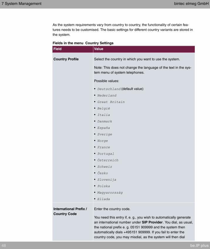
As the system requirements vary from country to country, the functionality of certain fea-
tures needs to be customised. The basic settings for different country variants are stored in
the system.
Fields in the menu Country Settings
Field Value
Country Profile Select the country in which you want to use the system.
Note: This does not change the language of the text in the sys-
tem menu of system telephones.
Possible values:
• (default value)
•
•
•
•
•
•
•
•
•
•
•
•
•
•
•
•
•
International Prefix /
Country Code
Enter the country code.
You need this entry if, e. g., you wish to automatically generate
an international number under SIP Provider. You dial, as usual,
the national prefix e. g. 05151 909999 and the system then
automatically dials +495151 909999. If you fail to enter the
country code, you may misdial, as the system will then dial
7 System Management bintec elmeg GmbH
48 be.IP plus
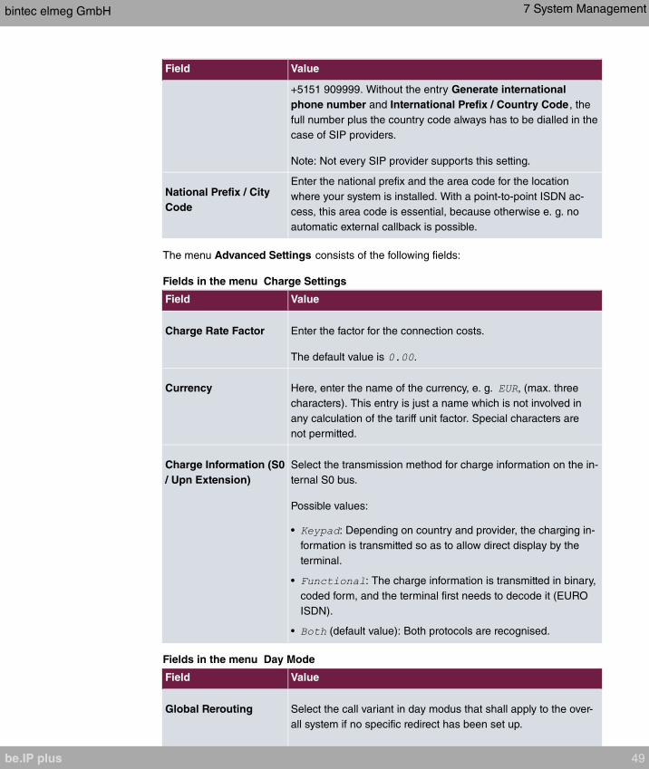
Field Value
+5151 909999. Without the entry Generate international
phone number and International Prefix / Country Code , the
full number plus the country code always has to be dialled in the
case of SIP providers.
Note: Not every SIP provider supports this setting.
National Prefix / City
Code
Enter the national prefix and the area code for the location
where your system is installed. With a point-to-point ISDN ac-
cess, this area code is essential, because otherwise e. g. no
automatic external callback is possible.
The menu Advanced Settings consists of the following fields:
Fields in the menu Charge Settings
Field Value
Charge Rate Factor Enter the factor for the connection costs.
The default value is .
Currency Here, enter the name of the currency, e. g. , (max. three
characters). This entry is just a name which is not involved in
any calculation of the tariff unit factor. Special characters are
not permitted.
Charge Information (S0
/ Upn Extension)
Select the transmission method for charge information on the in-
ternal S0 bus.
Possible values:
• : Depending on country and provider, the charging in-
formation is transmitted so as to allow direct display by the
terminal.
• : The charge information is transmitted in binary,
coded form, and the terminal first needs to decode it (EURO
ISDN).
• (default value): Both protocols are recognised.
Fields in the menu Day Mode
Field Value
Global Rerouting Select the call variant in day modus that shall apply to the over-
all system if no specific redirect has been set up.
bintec elmeg GmbH 7 System Management
be.IP plus 49
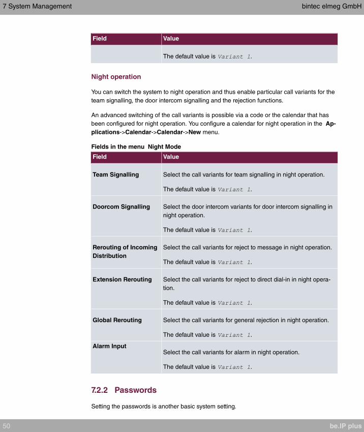
Field Value
The default value is .
Night operation
You can switch the system to night operation and thus enable particular call variants for the
team signalling, the door intercom signalling and the rejection functions.
An advanced switching of the call variants is possible via a code or the calendar that has
been configured for night operation. You configure a calendar for night operation in the Ap-
plications->Calendar->Calendar->New menu.
Fields in the menu Night Mode
Field Value
Team Signalling Select the call variants for team signalling in night operation.
The default value is .
Doorcom Signalling Select the door intercom variants for door intercom signalling in
night operation.
The default value is .
Rerouting of Incoming
Distribution
Select the call variants for reject to message in night operation.
The default value is .
Extension Rerouting Select the call variants for reject to direct dial-in in night opera-
tion.
The default value is .
Global Rerouting Select the call variants for general rejection in night operation.
The default value is .
Alarm InputSelect the call variants for alarm in night operation.
The default value is .
7.2.2 Passwords
Setting the passwords is another basic system setting.
7 System Management bintec elmeg GmbH
50 be.IP plus
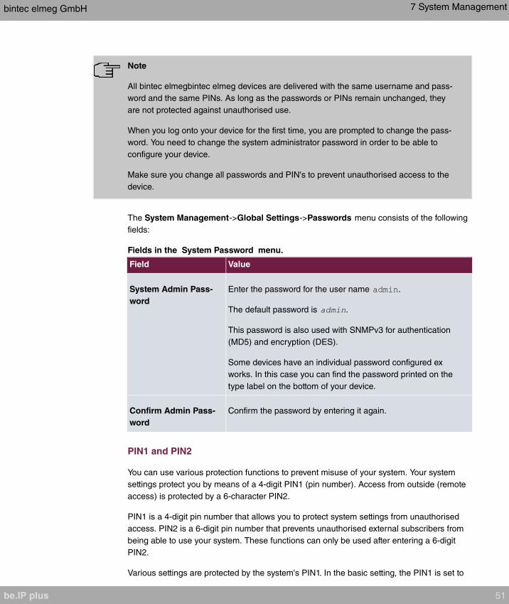
Note
All bintec elmegbintec elmeg devices are delivered with the same username and pass-
word and the same PINs. As long as the passwords or PINs remain unchanged, they
are not protected against unauthorised use.
When you log onto your device for the first time, you are prompted to change the pass-
word. You need to change the system administrator password in order to be able to
configure your device.
Make sure you change all passwords and PIN's to prevent unauthorised access to the
device.
The System Management->Global Settings->Passwords menu consists of the following
fields:
Fields in the System Password menu.
Field Value
System Admin Pass-
word
Enter the password for the user name .
The default password is .
This password is also used with SNMPv3 for authentication
(MD5) and encryption (DES).
Some devices have an individual password configured ex
works. In this case you can find the password printed on the
type label on the bottom of your device.
Confirm Admin Pass-
word
Confirm the password by entering it again.
PIN1 and PIN2
You can use various protection functions to prevent misuse of your system. Your system
settings protect you by means of a 4-digit PIN1 (pin number). Access from outside (remote
access) is protected by a 6-character PIN2.
PIN1 is a 4-digit pin number that allows you to protect system settings from unauthorised
access. PIN2 is a 6-digit pin number that prevents unauthorised external subscribers from
being able to use your system. These functions can only be used after entering a 6-digit
PIN2.
Various settings are protected by the system's PIN1. In the basic setting, the PIN1 is set to
bintec elmeg GmbH 7 System Management
be.IP plus 51
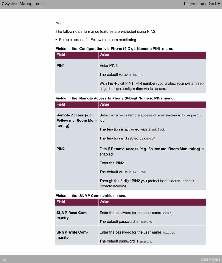
.
The following performance features are protected using PIN2:
• Remote access for Follow me, room monitoring
Fields in the Configuration via Phone (4-Digit Numeric PIN) menu.
Field Value
PIN1 Enter PIN1.
The default value is .
With the 4-digit PIN1 (PIN number) you protect your system set-
tings through configuration via telephone.
Fields in the Remote Access to Phone (6-Digit Numeric PIN) menu.
Field Value
Remote Access (e.g.
Follow me, Room Mon-
itoring)
Select whether a remote access of your system is to be permit-
ted.
The function is activated with .
The function is disabled by default.
PIN2 Only if Remote Access (e.g. Follow me, Room Monitoring) is
enabled.
Enter the PIN2.
The default value is .
Through the 6-digit PIN2 you protect from external access
(remote access).
Fields in the SNMP Communities menu.
Field Value
SNMP Read Com-
munity
Enter the password for the user name .
The default password is .
SNMP Write Com-
munity
Enter the password for the user name .
The default password is .
7 System Management bintec elmeg GmbH
52 be.IP plus

Field in the Global Password Options menu
Field Value
Show passwords and
keys in clear text
Define whether the passwords are to be displayed in clear text
(plain text).
The function is enabled with
The function is disabled by default.
If you activate the function, all passwords and keys in all menus
are displayed and can be edited in plain text.
One exception is IPSec keys. They can only be entered in plain
text. After pressing OK or calling the menu again, they are dis-
played as asterisks.
7.2.3 Date and Time
You need the system time for tasks such as correct time-stamps for system messages, or
accounting.
You have the following options for determining the system time (local time):
ISDN/Manual
The system time can be updated via ISDN, i.e. with every existing external connection the
date and time are taken from the ISDN. The date and time can also be entered manually,
e. g. if time and date are not sent in the ISDN or no time server is provided. The time re-
mains for approx. 3 hours after the system's power supply is switched off.
The clock switches from summer to winter time (and back) automatically. This is independ-
ent of the exchange time or the ntp server time. Summer time starts on the last Sunday in
March by switching from 2 a.m. to 3 a.m. The calendar-related or schedule-related
switches that are scheduled for the missing hour are then carried out. Winter time starts on
the last Sunday in October by switching from 3 a.m. to 2 a.m. The calendar-related or
schedule-related switches that are scheduled for the additional hour are then carried out.
Time server
You can obtain the system time automatically, e.g. using various time servers. To ensure
that the device uses the desired current time, you should configure one or more time serv-
ers.
bintec elmeg GmbH 7 System Management
be.IP plus 53

Note
If a method for automatically deriving the time is defined on the device, the values ob-
tained in this way automatically have higher priority. A manually entered system time is
therefore overwritten.
The menu System Management->Global Settings->Date and Time consists of the fol-
lowing fields:
Fields in the Basic Settings menu.
Field Description
Time Zone Select the time zone in which your device is installed.
You can select Universal Time Coordinated (UTC) plus or
minus the deviation in hours or a predefined location.
compact systems: The default value is .
Current Local Time The current date and current system time are shown here. The
entry cannot be changed.
Fields in the Manual Time Settings menu.
Field Description
Set Date Clicking into the field for adding a date brings up a standard cal-
ender. Clicking the desired date will enter it into the configura-
tion interface.
Set Time Enter a new time.
Format:
• Hour: hh
• Minute: mm
Fields in the Automatic Time Settings (Time Protocol) menu.
Field Description
ISDN Timeserver Determine whether the system time is to be updated via ISDN.
If a time server is configured, the time is only determined over
ISDN until a successful update is received from this time server.
Updating over ISDN is deactivated for the period in which the
7 System Management bintec elmeg GmbH
54 be.IP plus
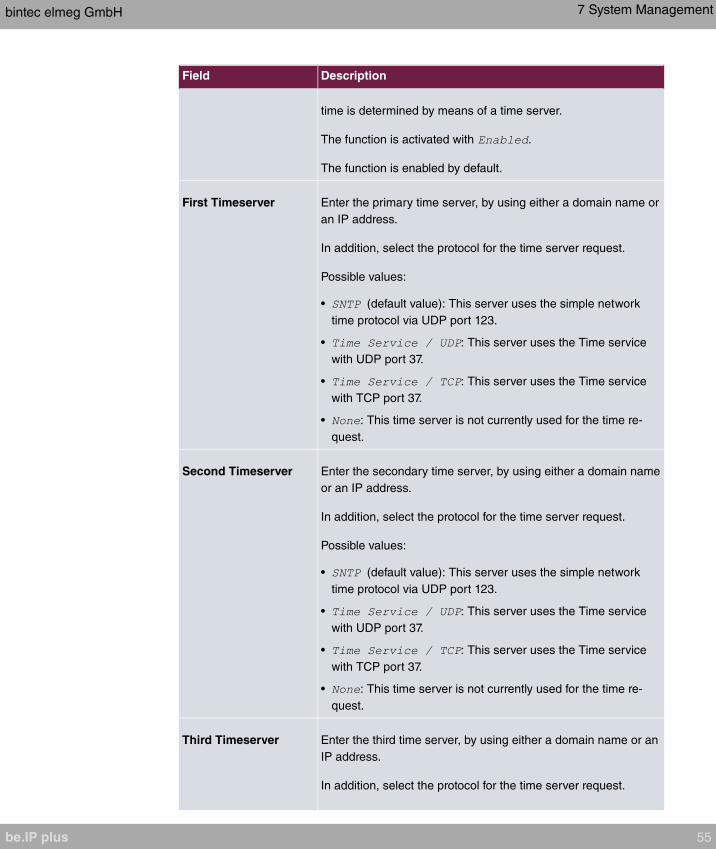
Field Description
time is determined by means of a time server.
The function is activated with .
The function is enabled by default.
First Timeserver Enter the primary time server, by using either a domain name or
an IP address.
In addition, select the protocol for the time server request.
Possible values:
• (default value): This server uses the simple network
time protocol via UDP port 123.
• : This server uses the Time service
with UDP port 37.
• : This server uses the Time service
with TCP port 37.
• : This time server is not currently used for the time re-
quest.
Second Timeserver Enter the secondary time server, by using either a domain name
or an IP address.
In addition, select the protocol for the time server request.
Possible values:
• (default value): This server uses the simple network
time protocol via UDP port 123.
• : This server uses the Time service
with UDP port 37.
• : This server uses the Time service
with TCP port 37.
• : This time server is not currently used for the time re-
quest.
Third Timeserver Enter the third time server, by using either a domain name or an
IP address.
In addition, select the protocol for the time server request.
bintec elmeg GmbH 7 System Management
be.IP plus 55

Field Description
Possible values:
• (default value): This server uses the simple network
time protocol via UDP port 123.
• : This server uses the Time service
with UDP port 37.
• : This server uses the Time service
with TCP port 37.
• : This time server is not currently used for the time re-
quest.
Time Update Interval Enter the time interval in minutes at which the time is automatic-
ally updated.
The default value is .
Time Update Policy Enter the time period after which the system attempts to contact
the time server again following a failed time update.
Possible values:
• (default value): The system attempts to contact the
time server after 1, 2, 4, 8, and 16 minutes.
• : For ten minutes, the system attempts to con-
tact the time server after 1, 2, 4, 8 seconds and then every 10
seconds.
• : For an unlimited period, the system attempts to
contact the time server after 1, 2, 4, 8 seconds and then every
10 seconds.
If certificates are used to encrypt data traffic in a VPN, it is ex-
tremely important that the correct time is set on the device. To
ensure this is the case, for Time Update Policy, select the
value .
Internal Time Server Select whether the internal timeserver is to be used.
The function is activated by selecting . Time requests
from a client will be answered with the current system time. This
is given as GMT, without offset.
The function is enabled by default. Clients' time requests are
answered in the LAN.
7 System Management bintec elmeg GmbH
56 be.IP plus

7.2.4 Timer
In the Timer menu you can configure the times at which particular system features are to
be switched on by default.
The menu System Management->Global Settings->Timer consists of the following fields:
Fields in the Basic Settings menu.
Field Description
Call Forwarding
(CFNR)
Enter the time in seconds after which a Call Forwarding
(CFNR) will be executed.
Possible values are to .
The default value is .
Direct Call Enter the time in seconds after which the configured number will
be dialled when the receiver is lifted.
You wish to set up a telephone for which the connection to a
specific number is established without entering the number (e.g.
emergency telephone). You are not at home. However, there is
someone at home who needs to be able to reach you quickly
and easily by telephone if necessary (e. g. children or grandpar-
ents). If you have set up the "Direct Call" function for one or
more telephones, the receiver of the corresponding telephone
only needs to be lifted. After a time period without further entries
set in configuration, the system automatically dials the con-
figured direct call number.
If you do not dial within the specified period from picking up the
receiver, automatic dialling is initiated.
Possible values are to .
The default value is .
External Door Connec-
tions
If an external telephone requests a door intercom call, here you
can set the time in seconds after which this call is forcefully ter-
minated.
Possible values:
•
bintec elmeg GmbH 7 System Management
be.IP plus 57
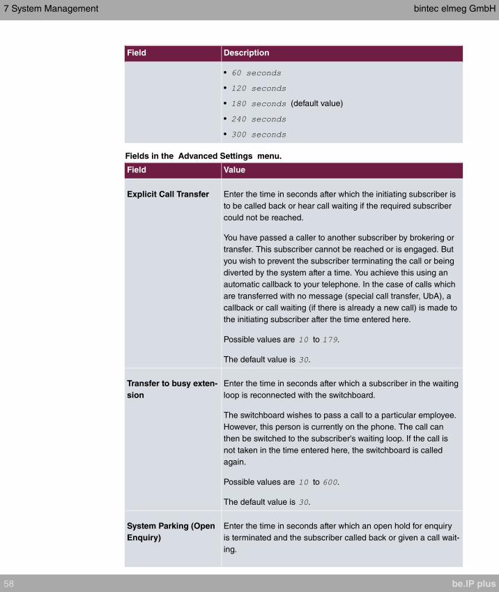
Field Description
•
•
• (default value)
•
•
Fields in the Advanced Settings menu.
Field Value
Explicit Call Transfer Enter the time in seconds after which the initiating subscriber is
to be called back or hear call waiting if the required subscriber
could not be reached.
You have passed a caller to another subscriber by brokering or
transfer. This subscriber cannot be reached or is engaged. But
you wish to prevent the subscriber terminating the call or being
diverted by the system after a time. You achieve this using an
automatic callback to your telephone. In the case of calls which
are transferred with no message (special call transfer, UbA), a
callback or call waiting (if there is already a new call) is made to
the initiating subscriber after the time entered here.
Possible values are to .
The default value is .
Transfer to busy exten-
sion
Enter the time in seconds after which a subscriber in the waiting
loop is reconnected with the switchboard.
The switchboard wishes to pass a call to a particular employee.
However, this person is currently on the phone. The call can
then be switched to the subscriber's waiting loop. If the call is
not taken in the time entered here, the switchboard is called
again.
Possible values are to .
The default value is .
System Parking (Open
Enquiry)
Enter the time in seconds after which an open hold for enquiry
is terminated and the subscriber called back or given a call wait-
ing.
7 System Management bintec elmeg GmbH
58 be.IP plus

Field Value
You are making a call and want to transfer it to a colleague. Un-
fortunately, you do not know where this colleague is. System
Parking (Open Enquiry) holds the caller in the system's queue.
You can now make an announcement from your telephone to
notify your colleague that the call is waiting. Using a code for
the open hold for enquiry, the colleague can take the call on any
telephone.
If a call waiting in the queue is not taken by a subscriber within
the time entered here, the initiating subscriber is called back or
given a call waiting.
Possible values are to .
The default value is .
7.2.5 System Licences
This chapter describes how to activate the functions of the software licences you have pur-
chased.
The following licence types exist:
• Licences already available in the device's ex works state
• Free extra licences
• Extra licences at additional cost
The data sheet for your device tells you which licences are available in the device's ex
works state and which can also be obtained free of charge or at additional cost. You can
access this data sheet at www.bintec-elmeg.com .
Entering licence data
You can obtain the licence data for extra licences via the online licensing pages in the sup-
port section at www.bintec-elmeg.com . Please follow the online licensing instructions.
(Please also note the information on the licence card for licences at additional cost.) You
will then receive an e-mail containing the following data:
• Licence Key and
• Licence Serial Number.
You enter this data in the System Management->Global Settings->System
Licences->New menu.
bintec elmeg GmbH 7 System Management
be.IP plus 59

In the System Management->Global Settings->System Licences->New menu, a list of
all registered licences is displayed (Description, Licence Type, Licence Serial Number,
Status).
Possible values for Status
Licence Meaning
OK Subsystem is activated.
Not OK Subsystem is not activated.
Not supported You have entered a licence for a subsystem your device does
not support.
In addition, above the list is shown the System Licence ID required for online licensing.
Note
To restore the standard licences for a device, click the Default Licences button
(standard licences).
7.2.5.1 Edit or New
Choose the icon to edit existing entries. Choose the New button to enter more licences.
Activating extra licences
You activate extra licences by adding the received licence information in the System Man-
agement->Global Settings->System Licences->New menu.
The menu System Management->Global Settings->System Licences->New consists of
the following fields:
Fields in the Basic Settings menu.
Field Value
Licence Serial Number Enter the licence serial number you received when you bought
the licence.
Licence Key Enter the licence key you received by e-mail.
Note
If is displayed as the status:
• Enter the licence data again.
7 System Management bintec elmeg GmbH
60 be.IP plus
• Check your hardware serial number.
If is displayed as the status, you have entered a license for a sub-
system that your device does not support. This means you cannot use the functions of
this licence.
Deactivating a licence
Proceed as follows to deactivate a licence:
(1) Go to System Management->Global Settings->System Licences->New.
(2) Press the icon in the line containing the licence you want to delete.
(3) Confirm with OK.
The licence is deactivated. You can reactivate your additional licence at any time by enter-
ing the valid licence key and licence serial number.
7.3 Access Codes
In your day-to-day work you have employed codes to use particular features and you wish
to use them again with your new system. However, other codes are set for these features
in the basic setting. No problem - you can change the codes for different features. So you
can use your usual codes for these features in the future.
7.3.1 Alternative Access Codes
You use the Alternative Access Codes menu to configure the system's access number
plan.
The access number can be set individually for some performance features in the system
configuration. The access number preset in the system is supplemented with a call number
from the system's internal number plan. For performance features Open inquiry and
Bundles, several access codes can be assigned. The performance feature with modified
access number is operated as described for the corresponding performance feature. You
can use the modified access number (internal number) or the access number described in
the user guide (excluding dialling code).
The System Management->Access Codes->Alternative Access Codes menu consists
of the following fields:
Fields in the Basic Settings menu.
bintec elmeg GmbH 7 System Management
be.IP plus 61
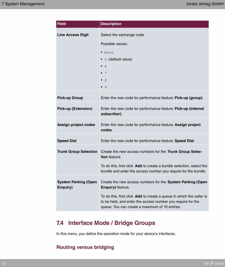
Field Description
Line Access Digit Select the exchange code.
Possible values:
•
• (default value)
•
•
•
•
Pick-up Group Enter the new code for performance feature Pick-up (group).
Pick-up (Extension) Enter the new code for performance feature Pick-up (internal
subscriber).
Assign project codes Enter the new code for performance feature Assign project
codes.
Speed Dial Enter the new code for performance feature Speed Dial.
Trunk Group Selection Create the new access numbers for the Trunk Group Selec-
tion feature.
To do this, first click Add to create a bundle selection, select the
bundle and enter the access number you require for the bundle.
System Parking (Open
Enquiry)
Create the new access numbers for the System Parking (Open
Enquiry) feature.
To do this, first click Add to create a queue in which the caller is
to be held, and enter the access number you require for the
queue. You can create a maximum of 10 entries.
7.4 Interface Mode / Bridge Groups
In this menu, you define the operation mode for your device's interfaces.
Routing versus bridging
7 System Management bintec elmeg GmbH
62 be.IP plus
Bridging connects networks of the same type. In contrast to routing, bridges operate at lay-
er 2 of the OSI model (data link layer), are independent of higher-level protocols and trans-
mit data packets using MAC addresses. Data transmission is transparent, which means the
information contained in the data packets is not interpreted.
With routing, different networks are connected at layer 3 (network layer) of the OSI model
and information is routed from one network to the other.
Conventions for port/interface names
If your device has a radio port, it receives the interface name WLAN. If there are several ra-
dio modules, the names of wireless ports in the user interface of your device are made up
of the following parts:
(a) WLAN
(b) Number of the physical port (1 or 2)
Example: The name of the Ethernet port is made up of the following parts:
(a) ETH
(b) Number of the port
Example:
The name of the interface connected to an Ethernet port is made up of the following parts:
(a) Abbreviation for interface type, whereby stands for internet.
(b) Number of the Ethernet port
(c) Number of the interface
Example: (first interface on the first Ethernet port)
The name of the bridge group is made up of the following parts:
(a) Abbreviation for interface type, whereby stands for bridge group.
(b) Number of the bridge group
Example: (first bridge group)
The name of the wireless network (VSS) is made up of the following parts:
Abbreviation for interface type, whereby stands for wireless network.
(a) Number of the wireless module
(b) Number of the interface
bintec elmeg GmbH 7 System Management
be.IP plus 63
Example: (first wireless network on the first wireless module)
The name of the bridge link is made up of the following parts:
(a) Abbreviation for interface type
(b) Number of the wireless module on which the bridge link is configured
(c) Number of the bridge link
Example: (first bridge link on the first wireless module)
The name of the client link is made up of the following parts:
(a) Abbreviation for interface type
(b) Number of the wireless module on which the client link is configured
(c) Number of the client link
Example: (first client link on the first wireless module)
The name of the virtual interface connected to an Ethernet port is made up of the following
parts:
(a) Abbreviation for interface type
(b) Number of the Ethernet port
(c) Number of the interface connected to the Ethernet port
(d) Number of the virtual interface
Example: (first virtual interface based on the first interface on the first Ethernet
port)
7.4.1 Interfaces
You define separately whether each interface is to operate in routing or bridging mode.
If you want to set bridging mode, you can either use existing bridge groups or create a new
bridge group.
The default setting for all existing interfaces is routing mode. When selecting the option
for Mode / Bridge Group, a bridge group, i.e. , etc. is
automatically created and the interface is run in bridging mode.
The System Management->Interface Mode / Bridge Groups->Interfaces menu consists
of the following fields:
Fields in the Interfaces menu.
7 System Management bintec elmeg GmbH
64 be.IP plus
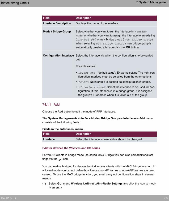
Field Description
Interface Description Displays the name of the interface.
Mode / Bridge Group Select whether you want to run the interface in
or whether you want to assign the interface to an existing
( , etc.) or new bridge group ( ).
When selecting , a new bridge group is
automatically created after you click the OK button.
Configuration Interface Select the interface via which the configuration is to be carried
out.
Possible values:
• (default value): Ex works setting The right con-
figuration interface must be selected from the other options.
• : No interface is defined as configuration interface.
• : Select the interface to be used for con-
figuration. If this interface is in a bridge group, it is assigned
the group's IP address when it is taken out of the group.
7.4.1.1 Add
Choose the Add button to edit the mode of PPP interfaces.
The System Management->Interface Mode / Bridge Groups->Interfaces->Add menu
consists of the following fields:
Fields in the Interfaces menu.
Field Description
Interface Select the interface whose status should be changed.
Edit for devices the WIxxxxn and RS series
For WLAN clients in bridge mode (so-called MAC Bridge) you can also edit additional set-
tings via the icon.
You can realise bridging for devices behind access clients with the MAC Bridge function. In
wildcard mode you cannot define how Unicast non-IP frames or non-ARP frames are pro-
cessed. To use the MAC bridge function, you must carry out configuration steps in several
menus.
(1) Select GUI menu Wireless LAN->WLAN->Radio Settings and click the icon to modi-
fy an entry.
bintec elmeg GmbH 7 System Management
be.IP plus 65
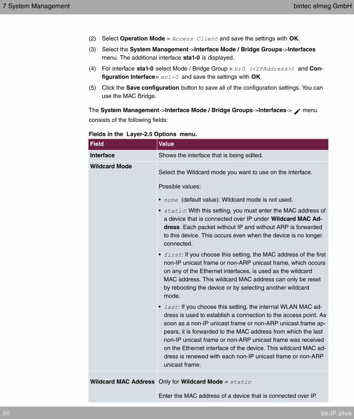
(2) Select Operation Mode = and save the settings with OK.
(3) Select the System Management->Interface Mode / Bridge Groups->Interfaces
menu. The additional interface sta1-0 is displayed.
(4) For interface sta1-0 select Mode / Bridge Group = and Con-
figuration Interface= and save the settings with OK.
(5) Click the Save configuration button to save all of the configuration settings. You can
use the MAC Bridge.
The System Management->Interface Mode / Bridge Groups->Interfaces-> menu
consists of the following fields:
Fields in the Layer-2.5 Options menu.
Field Value
Interface Shows the interface that is being edited.
Wildcard ModeSelect the Wildcard mode you want to use on the interface.
Possible values:
• (default value): Wildcard mode is not used.
• : With this setting, you must enter the MAC address of
a device that is connected over IP under Wildcard MAC Ad-
dress. Each packet without IP and without ARP is forwarded
to this device. This occurs even when the device is no longer
connected.
• : If you choose this setting, the MAC address of the first
non-IP unicast frame or non-ARP unicast frame, which occurs
on any of the Ethernet interfaces, is used as the wildcard
MAC address. This wildcard MAC address can only be reset
by rebooting the device or by selecting another wildcard
mode.
• : If you choose this setting, the internal WLAN MAC ad-
dress is used to establish a connection to the access point. As
soon as a non-IP unicast frame or non-ARP unicast frame ap-
pears, it is forwarded to the MAC address from which the last
non-IP unicast frame or non-ARP unicast frame was received
on the Ethernet interface of the device. This wildcard MAC ad-
dress is renewed with each non-IP unicast frame or non-ARP
unicast frame.
Wildcard MAC Address Only for Wildcard Mode =
Enter the MAC address of a device that is connected over IP.
7 System Management bintec elmeg GmbH
66 be.IP plus
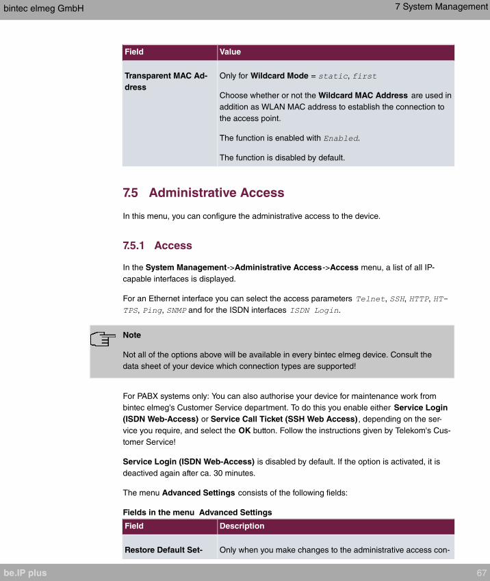
Field Value
Transparent MAC Ad-
dress
Only for Wildcard Mode = ,
Choose whether or not the Wildcard MAC Address are used in
addition as WLAN MAC address to establish the connection to
the access point.
The function is enabled with .
The function is disabled by default.
7.5 Administrative Access
In this menu, you can configure the administrative access to the device.
7.5.1 Access
In the System Management->Administrative Access->Access menu, a list of all IP-
capable interfaces is displayed.
For an Ethernet interface you can select the access parameters , , ,
, , and for the ISDN interfaces .
Note
Not all of the options above will be available in every bintec elmeg device. Consult the
data sheet of your device which connection types are supported!
For PABX systems only: You can also authorise your device for maintenance work from
bintec elmeg's Customer Service department. To do this you enable either Service Login
(ISDN Web-Access) or Service Call Ticket (SSH Web Access) , depending on the ser-
vice you require, and select the OK button. Follow the instructions given by Telekom's Cus-
tomer Service!
Service Login (ISDN Web-Access) is disabled by default. If the option is activated, it is
deactived again after ca. 30 minutes.
The menu Advanced Settings consists of the following fields:
Fields in the menu Advanced Settings
Field Description
Restore Default Set- Only when you make changes to the administrative access con-
bintec elmeg GmbH 7 System Management
be.IP plus 67

Field Description
tings figuration are relevant access rules set up and activated. You
can restore the default settings with the icon.
7.5.1.1 Add
Select the Add button to configure administrative access for additional interfaces.
The System Management->Administrative Access->Access->Add menu consists of the
following fields:
Fields in the menu Access
Field Description
Interface Select the interface for which administrative access is to be con-
figured.
7.5.2 SSH
Your devices offers encrypted access to the shell. You can enable or disable this access in
the System Management->Administrative Access->SSH Enabled menu (standard
value). You can also access the options for configuring the SSH login.
You need an SSH client application, e.g. PuTTY, to be able to reach the SSH Daemon.
If you wish to use SSH Login together with the PuTTY client, you may need to comply with
some special configuration requirements, for which we have prepared FAQs. You will find
these in the Service/Support section at www.bintec-elmeg.com .
To be able to reach the shell of your device via an SSH client, make sure the settings for
the SSH Daemon and SSH client are the same.
Note
If configuration of an SSH connection is not possible, restart the device to initialise the
SSH Daemon correctly.
The System Management->Administrative Access->SSH menu consists of the following
fields:
Fields in the menu SSH (Secure Shell) Parameters
7 System Management bintec elmeg GmbH
68 be.IP plus

Field Value
SSH service active Select whether the SSH Daemon is to be enabled for the inter-
face.
The function is activated by selecting .
The function is enabled by default.
SSH PortHere you can enter the port via which the SSH connection is to
be established.
The default value is .
Maximum number of
concurrent connec-
tions
Enter the maximum number of simultaneously active SSH con-
nections.
The default value is .
Fields in the menu Authentication and Encryption Parameters
Field Value
Encryption Algorithms Select the algorithms that are to be used to encrypt the SSH
connection.
Possible options:
•
•
•
•
By default , and are enabled.
Hashing Algorithms Select the algorithms that are to be available for message au-
thentication of the SSH connection.
Possible options:
•
•
•
By default , and are enabled.
bintec elmeg GmbH 7 System Management
be.IP plus 69

Fields in the menu Key Status
Field Value
RSA Key Status Shows the status of the RSA key.
If an RSA key has not been generated yet, is
displayed and a link, , is provided. If you select the
link, the generation process is triggered and the view is up-
dated. The status is displayed. When generation
has been completed successfully, the status changes from
to . If an error occurs during the gen-
eration, and the link are displayed
again. You can then repeat generation.
If the status is displayed, generation of a key is not
possible, for example because there is not enough space in the
FlashROM.
ECDSA Key Status Shows the status of the ECDSA key.
If no ECDSA key has yet been generated, is
displayed and a link, , is provided. If you select the
link, the generation process is triggered and the view is up-
dated. The status is displayed. When generation
has been completed successfully, the status changes from
to . If an error occurs during the gen-
eration, and the link are displayed
again. You can then repeat generation.
If the status is displayed, generation of a key is not
possible, for example because there is not enough space in the
FlashROM.
ED25519 Key Status Shows the status of the ED25519 key.
If an ED25519 key has not been generated yet,
is displayed and a link, , is provided. If you se-
lect the link, the generation process is triggered and the view is
updated. The status is displayed. When genera-
tion has been completed successfully, the status changes from
to . If an error occurs during the gen-
eration, and the link are displayed
again. You can then repeat generation.
If the status is displayed, generation of a key is not
7 System Management bintec elmeg GmbH
70 be.IP plus

Field Value
possible, for example because there is not enough space in the
FlashROM.
The menu Advanced Settings consists of the following fields:
Fields in the menu Advanced Settings
Field Value
Login Grace TimeEnter the time (in seconds) that is available for establishing the
connection. If a client cannot be successfully authenticated dur-
ing this time, the connection is terminated.
The default value is seconds.
Compression Select whether data compression should be used.
The function is activated by selecting .
The function is disabled by default.
TCP Keepalives Select whether the device is to send keepalive packets.
The function is activated by selecting .
The function is enabled by default.
Logging Level Select the syslog level for the syslog messages generated by
the SSH Daemon.
Possible settings:
• (default value): Fatal and simple errors of the
SSH Daemon and information messages are recorded.
• : Only fatal errors of the SSH Daemon are recorded.
• : Fatal and simple errors of the SSH Daemon are re-
corded.
• : All messages are recorded.
bintec elmeg GmbH 7 System Management
be.IP plus 71
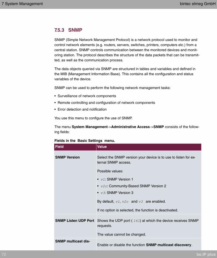
7.5.3 SNMP
SNMP (Simple Network Management Protocol) is a network protocol used to monitor and
control network elements (e.g. routers, servers, switches, printers, computers etc.) from a
central station. SNMP controls communication between the monitored devices and monit-
oring station. The protocol describes the structure of the data packets that can be transmit-
ted, as well as the communication process.
The data objects queried via SNMP are structured in tables and variables and defined in
the MIB (Management Information Base). This contains all the configuration and status
variables of the device.
SNMP can be used to perform the following network management tasks:
• Surveillance of network components
• Remote controlling and configuration of network components
• Error detection and notification
You use this menu to configure the use of SNMP.
The menu System Management->Administrative Access->SNMP consists of the follow-
ing fields:
Fields in the Basic Settings menu.
Field Value
SNMP Version Select the SNMP version your device is to use to listen for ex-
ternal SNMP access.
Possible values:
• : SNMP Version 1
• : Community-Based SNMP Version 2
• : SNMP Version 3
By default, , and are enabled.
If no option is selected, the function is deactivated.
SNMP Listen UDP Port Shows the UDP port ( ) at which the device receives SNMP
requests.
The value cannot be changed.
SNMP multicast dis-Enable or disable the function SNMP multicast discovery.
7 System Management bintec elmeg GmbH
72 be.IP plus
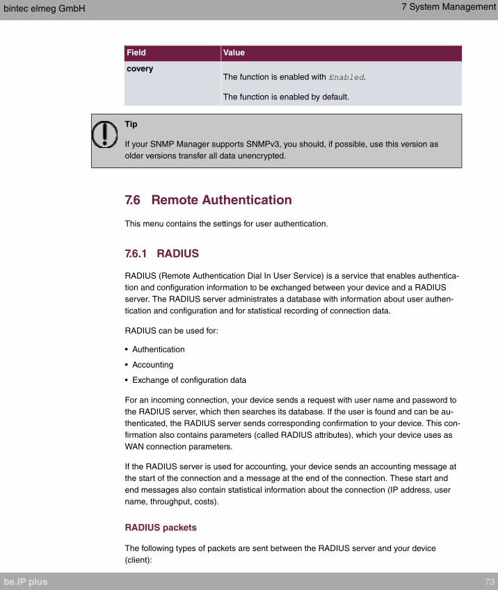
Field Value
coveryThe function is enabled with .
The function is enabled by default.
Tip
If your SNMP Manager supports SNMPv3, you should, if possible, use this version as
older versions transfer all data unencrypted.
7.6 Remote Authentication
This menu contains the settings for user authentication.
7.6.1 RADIUS
RADIUS (Remote Authentication Dial In User Service) is a service that enables authentica-
tion and configuration information to be exchanged between your device and a RADIUS
server. The RADIUS server administrates a database with information about user authen-
tication and configuration and for statistical recording of connection data.
RADIUS can be used for:
• Authentication
• Accounting
• Exchange of configuration data
For an incoming connection, your device sends a request with user name and password to
the RADIUS server, which then searches its database. If the user is found and can be au-
thenticated, the RADIUS server sends corresponding confirmation to your device. This con-
firmation also contains parameters (called RADIUS attributes), which your device uses as
WAN connection parameters.
If the RADIUS server is used for accounting, your device sends an accounting message at
the start of the connection and a message at the end of the connection. These start and
end messages also contain statistical information about the connection (IP address, user
name, throughput, costs).
RADIUS packets
The following types of packets are sent between the RADIUS server and your device
(client):
bintec elmeg GmbH 7 System Management
be.IP plus 73

Packet types
Field Value
ACCESS_REQUEST Client -> Server
If an access request is received by your device, a request is
sent to the RADIUS server if no corresponding connection part-
ner has been found on your device.
ACCESS_ACCEPT Server -> Client
If the RADIUS server has authenticated the information con-
tained in the ACCESS_REQUEST, it sends an AC-
CESS_ACCEPT to your device together with the parameters
used for setting up the connection.
ACCESS_REJECT Server -> Client
If the information contained in the ACCESS_REQUEST does
not correspond to the information in the user database of the
RADIUS server, it sends an ACCESS_REJECT to reject the
connection.
ACCOUNTING_START Client -> Server
If a RADIUS server is used for accounting, your device sends
an accounting message to the RADIUS server at the start of
each connection.
ACCOUNTING_STOP Client -> Server
If a RADIUS server is used for accounting, your device sends
an accounting message to the RADIUS server at the end of
each connection.
A list of all entered RADIUS servers is displayed in the System Management->Remote
Authentication->RADIUS menu.
7.6.1.1 Edit or New
Choose the icon to edit existing entries. Choose the New button to add RADIUS serv-
ers.
The System Management->Remote Authentication->RADIUS->New menu consists of
the following fields:
7 System Management bintec elmeg GmbH
74 be.IP plus

Fields in the Basic Parameters menu.
Field Value
Authentication Type Select what the RADIUS server is to be used for.
Possible values:
• (default value only for PPP connec-
tions): The RADIUS server is used for controlling access to a
network.
• (for PPP connections only): The RADIUS serv-
er is used for recording statistical call data.
• : The RADIUS server is used for
controlling access to the SNMP shell of your device.
• : The RADIUS server is used for
sending configuration data for IPSec peers to your device.
• : The RADIUS server is used for controlling
access to a wireless network.
• : The RADIUS server is used for authenticating IPSec
peers via XAuth.
Vendor Mode Only for Authentication Type =
In hotspot applications, select the mode define by the provider.
In standard applications, leave the value set to .
Possible values for hotspot applications:
• : For France Telecom hotspot applications.
• : For hotspot applications.
Server IP Address Enter the IP address of the RADIUS server.
RADIUS Secret Enter the shared password used for communication between
the RADIUS server and your device.
Default User Password Some Radius servers require a user password for each RADI-
US request. Enter the password that your device sends as the
default user password in the prompt for the dialout routes on the
RADIUS server.
Priority If a number of RADIUS server entries were created, the server
with the highest priority is used first. If this server does not an-
bintec elmeg GmbH 7 System Management
be.IP plus 75
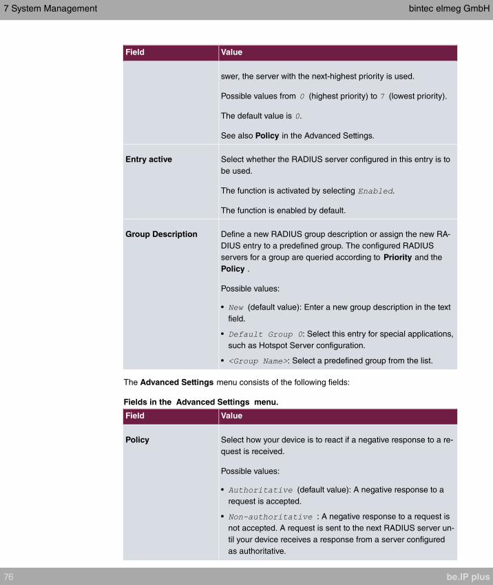
Field Value
swer, the server with the next-highest priority is used.
Possible values from (highest priority) to (lowest priority).
The default value is .
See also Policy in the Advanced Settings.
Entry active Select whether the RADIUS server configured in this entry is to
be used.
The function is activated by selecting .
The function is enabled by default.
Group Description Define a new RADIUS group description or assign the new RA-
DIUS entry to a predefined group. The configured RADIUS
servers for a group are queried according to Priority and the
Policy .
Possible values:
• (default value): Enter a new group description in the text
field.
• : Select this entry for special applications,
such as Hotspot Server configuration.
• : Select a predefined group from the list.
The Advanced Settings menu consists of the following fields:
Fields in the Advanced Settings menu.
Field Value
Policy Select how your device is to react if a negative response to a re-
quest is received.
Possible values:
• (default value): A negative response to a
request is accepted.
• : A negative response to a request is
not accepted. A request is sent to the next RADIUS server un-
til your device receives a response from a server configured
as authoritative.
7 System Management bintec elmeg GmbH
76 be.IP plus
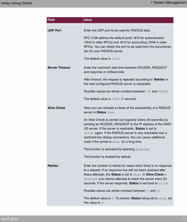
Field Value
UDP Port Enter the UDP port to be used for RADIUS data.
RFC 2138 defines the default ports 1812 for authentication
(1645 in older RFCs) and 1813 for accounting (1646 in older
RFCs). You can obtain the port to be used from the documenta-
tion for your RADIUS server.
The default value is .
Server Timeout Enter the maximum wait time between ACCESS_REQUEST
and response in milliseconds.
After timeout, the request is repeated according to Retries or
the next configured RADIUS server is requested.
Possible values are whole numbers between and .
The default value is (1 second).
Alive Check Here you can activate a check of the accessibility of a RADIUS
server in Status .
An Alive Check is carried out regularly (every 20 seconds) by
sending an ACCESS_REQUEST to the IP address of the RADI-
US server. If the server is reachable, Status is set to
again. If the RADIUS server is only reachable over a
switched line (dialup connection), this can cause additional
costs if the server is for a long time.
The function is activated by selecting .
The function is enabled by default.
Retries Enter the number of retries for cases when there is no response
to a request. If an response has still not been received after
these attempts, the Status is set to . In Alive Check =
your device attempts to reach the server every 20
seconds. If the server responds, Status is set back to .
Possible values are whole numbers between and .
The default value is . To prevent Status being set to , set
this value to .
bintec elmeg GmbH 7 System Management
be.IP plus 77
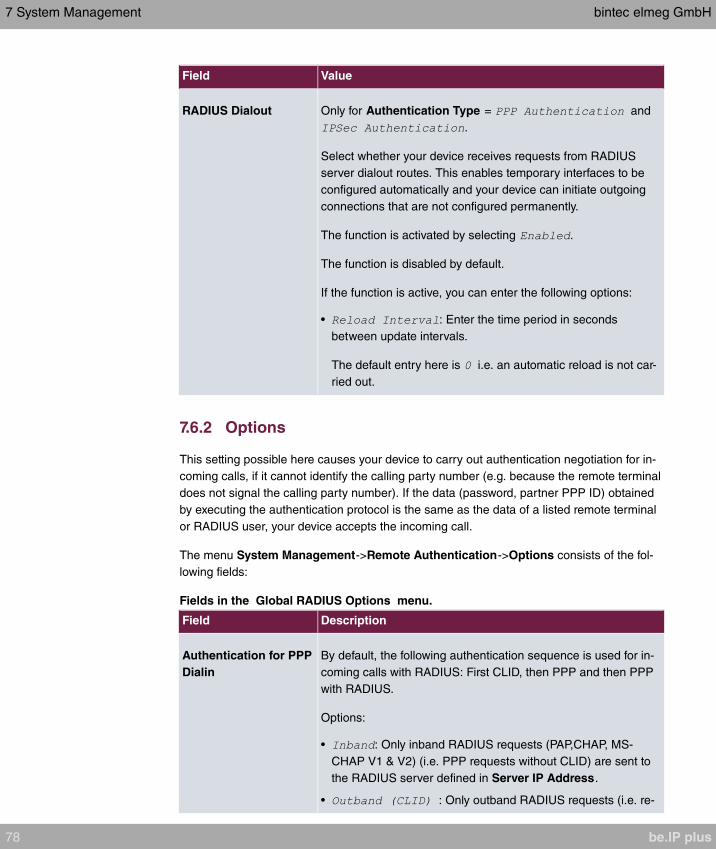
Field Value
RADIUS Dialout Only for Authentication Type = and
.
Select whether your device receives requests from RADIUS
server dialout routes. This enables temporary interfaces to be
configured automatically and your device can initiate outgoing
connections that are not configured permanently.
The function is activated by selecting .
The function is disabled by default.
If the function is active, you can enter the following options:
• : Enter the time period in seconds
between update intervals.
The default entry here is i.e. an automatic reload is not car-
ried out.
7.6.2 Options
This setting possible here causes your device to carry out authentication negotiation for in-
coming calls, if it cannot identify the calling party number (e.g. because the remote terminal
does not signal the calling party number). If the data (password, partner PPP ID) obtained
by executing the authentication protocol is the same as the data of a listed remote terminal
or RADIUS user, your device accepts the incoming call.
The menu System Management->Remote Authentication->Options consists of the fol-
lowing fields:
Fields in the Global RADIUS Options menu.
Field Description
Authentication for PPP
Dialin
By default, the following authentication sequence is used for in-
coming calls with RADIUS: First CLID, then PPP and then PPP
with RADIUS.
Options:
• : Only inband RADIUS requests (PAP,CHAP, MS-
CHAP V1 & V2) (i.e. PPP requests without CLID) are sent to
the RADIUS server defined in Server IP Address.
• : Only outband RADIUS requests (i.e. re-
7 System Management bintec elmeg GmbH
78 be.IP plus
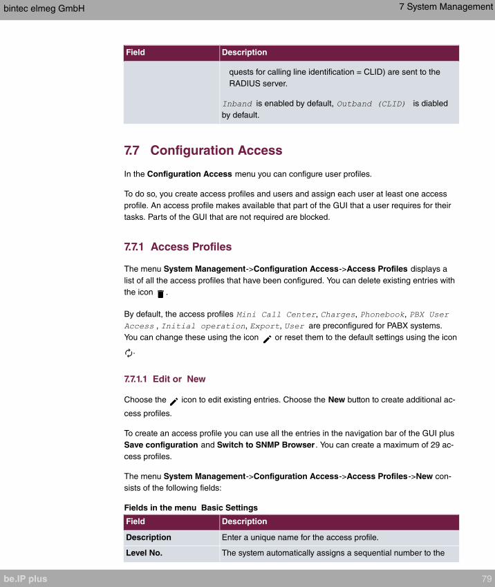
Field Description
quests for calling line identification = CLID) are sent to the
RADIUS server.
is enabled by default, is diabled
by default.
7.7 Configuration Access
In the Configuration Access menu you can configure user profiles.
To do so, you create access profiles and users and assign each user at least one access
profile. An access profile makes available that part of the GUI that a user requires for their
tasks. Parts of the GUI that are not required are blocked.
7.7.1 Access Profiles
The menu System Management->Configuration Access->Access Profiles displays a
list of all the access profiles that have been configured. You can delete existing entries with
the icon .
By default, the access profiles , , ,
, , , are preconfigured for PABX systems.
You can change these using the icon or reset them to the default settings using the icon
.
7.7.1.1 Edit or New
Choose the icon to edit existing entries. Choose the New button to create additional ac-
cess profiles.
To create an access profile you can use all the entries in the navigation bar of the GUI plus
Save configuration and Switch to SNMP Browser . You can create a maximum of 29 ac-
cess profiles.
The menu System Management->Configuration Access->Access Profiles->New con-
sists of the following fields:
Fields in the menu Basic Settings
Field Description
Description Enter a unique name for the access profile.
Level No. The system automatically assigns a sequential number to the
bintec elmeg GmbH 7 System Management
be.IP plus 79
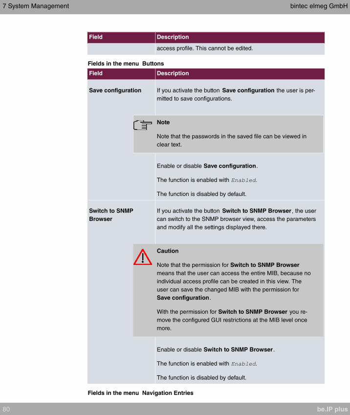
Field Description
access profile. This cannot be edited.
Fields in the menu Buttons
Field Description
Save configuration If you activate the button Save configuration the user is per-
mitted to save configurations.
Note
Note that the passwords in the saved file can be viewed in
clear text.
Enable or disable Save configuration.
The function is enabled with .
The function is disabled by default.
Switch to SNMP
Browser
If you activate the button Switch to SNMP Browser , the user
can switch to the SNMP browser view, access the parameters
and modify all the settings displayed there.
Caution
Note that the permission for Switch to SNMP Browser
means that the user can access the entire MIB, because no
individual access profile can be created in this view. The
user can save the changed MIB with the permission for
Save configuration.
With the permission for Switch to SNMP Browser you re-
move the configured GUI restrictions at the MIB level once
more.
Enable or disable Switch to SNMP Browser .
The function is enabled with .
The function is disabled by default.
Fields in the menu Navigation Entries
7 System Management bintec elmeg GmbH
80 be.IP plus

Field Description
Menus You see all the menus from the GUI's navigation bar. Menus
that contain at least one sub-menu are flagged by and .
The icon indicates pages.
When you create a new access profile, no elements are as-
signed yet, i.e. all the available menus, sub-menus and pages
are flagged with the icon .
Each element in the navigation bar can have three values. Click
the icon in the row you want to display these three values.
Possible values:
• : The menu and all its lower-level menus are blocked.
• : The menu is released. Lower-level menus may need
to be specifically released.
• : The menu and all its lower-level menus are re-
leased.
You can select and in the corresponding
row to assign elements to the current access profile.
Elements that are assigned to the current access profile are
flagged with the icon .
indicates a menu that is blocked, but which has at least one
released sub-menu.
7.7.2 Users
The menu System Management->Configuration Access->Users displays a list of all the
users that have been configured. You can delete existing entries with the icon .
There are no preconfigured users.
You can click the button to display the details of the configured user. You can see which
fields and menus are assigned to the user.
The icon means that Read-only is permitted. If a row is flagged with the icon
the information is released for reading and writing. The icon indicates blocked
entries.
bintec elmeg GmbH 7 System Management
be.IP plus 81

7.7.2.1 Edit or New
Choose the icon to edit existing entries. Choose the New button to enter additional
users.
The menu System Management->Configuration Access->Users->New consists of the
following fields:
Fields in the menu Basic Settings
Field Description
User Enter a unique name for the user.
Password Enter a password for the user.
User must change
password
The administrator can use the option User must change pass-
word to specify that the user must select their own password
the first time they log in. To do this, the option Save configura-
tion needs to be enabled in the menu Access Profiles . If this
option is not enabled, a warning message displays.
Enable or disable User must change password.
The function is enabled with .
The function is disabled by default.
Access Level Use Add to assign at least one access profile to the user. Se-
lecting Read-only specifies that the user can view the paramet-
ers of the access profile, but not change them. Selecting Read-
only is only possible if the option Switch to SNMP Browser in
the menu Access Profiles is not enabled.
If the option Switch to SNMP Browser is enabled, a warning
message displays because the user can switch to the SNMP
browser view, access the parameters and make any changes
they like. The option Read-only is not available in the SNMP
browser view.
If intersecting access profiles are assigned to a user, read and
write have a higher priority than Read-only. Buttons cannot be
set to the setting Read-only.
7 System Management bintec elmeg GmbH
82 be.IP plus

7.8 Certificates
An asymmetric cryptosystem is used to encrypt data to be transported in a network, to gen-
erate or check digital signatures and the authenticate users. A key pair consisting of a pub-
lic key and a private key is used to encrypt and decrypt the data.
For encryption the sender requires the public key of the recipient. The recipient decrypts
the data using his private key. To ensure that the public key is the real key of the recipient
and is not a forgery, a so-called digital certificate is required.
This confirms the authenticity and the owner of a public key. It is similar to an official pass-
port in that it confirms that the holder of the passport has certain characteristics, such as
gender and age, and that the signature on the passport is authentic. As there is more than
one certificate issuer, e.g. the passport office for a passport, and as such certificates can
be issued by several different issuers and in varying qualities, the trustworthiness of the is-
suer is extremely important. The quality of a certificate is regulated by the German Signa-
ture Act or respective EU Directives.
Certification authorities that issue so-called qualified certificates are organised in a hier-
archy with the Federal Network Agency as the higher certifying authority. The structure and
content of a certificate are stipulated by the standard used. X.509 is the most important and
the most commonly use standard for digital certificates. Qualified certificates are personal
and extremely trustworthy.
Digital certificates are part of a so-called Public Key Infrastructure (PKI). PKI refers to a
system that can issue, distribute and check digital certificates.
Certificates are issued for a specific period, usually one year, i.e. they have a limited valid-
ity period.
Your device is designed to use certificates for VPN connections and for voice connections
over Voice over IP.
7.8.1 Certificate List
A list of all existing certificates is displayed in the System
Management->Certificates->Certificate List menu.
7.8.1.1 Edit
Click the icon to display the content of the selected object (key, certificate, or request).
The certificates and keys themselves cannot be changed, but a few external attributes can
be changed, depending on the type of the selected entry.
bintec elmeg GmbH 7 System Management
be.IP plus 83
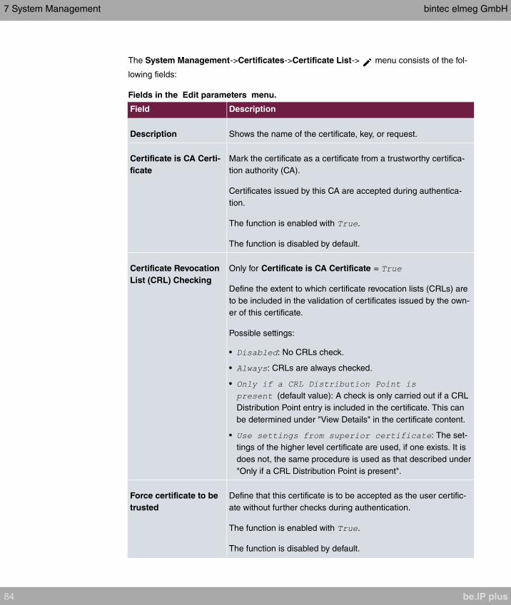
The System Management->Certificates->Certificate List-> menu consists of the fol-
lowing fields:
Fields in the Edit parameters menu.
Field Description
Description Shows the name of the certificate, key, or request.
Certificate is CA Certi-
ficate
Mark the certificate as a certificate from a trustworthy certifica-
tion authority (CA).
Certificates issued by this CA are accepted during authentica-
tion.
The function is enabled with .
The function is disabled by default.
Certificate Revocation
List (CRL) Checking
Only for Certificate is CA Certificate =
Define the extent to which certificate revocation lists (CRLs) are
to be included in the validation of certificates issued by the own-
er of this certificate.
Possible settings:
• : No CRLs check.
• : CRLs are always checked.
•
(default value): A check is only carried out if a CRL
Distribution Point entry is included in the certificate. This can
be determined under "View Details" in the certificate content.
• : The set-
tings of the higher level certificate are used, if one exists. It is
does not, the same procedure is used as that described under
"Only if a CRL Distribution Point is present".
Force certificate to be
trusted
Define that this certificate is to be accepted as the user certific-
ate without further checks during authentication.
The function is enabled with .
The function is disabled by default.
7 System Management bintec elmeg GmbH
84 be.IP plus
Caution
It is extremely important for VPN security that the integrity of all certificates manually
marked as trustworthy (certification authority and user certificates) is ensured. The dis-
played "fingerprints" can be used to check this integrity: Compare the displayed values
with the fingerprints specified by the issuer of the certificate (e.g. on the Internet). It is
sufficient to check one of the two values.
7.8.1.2 Certificate Request
Registration authority certificates in SCEP
If SCEP (Simple Certificate Enrollment Protocol) is used, your device also supports separ-
ate registration authority certificates.
Registration authority certificates are used by some Certificate Authorities (CAs) to handle
certain tasks (signature and encryption) during SCEP communication with separate keys,
and to delegate the operation to separate registration authorities, if applicable.
When a certificate is downloaded automatically, i.e. if CA Certificate =
is selected, all the certificates needed for the operation are loaded automatically.
If all the necessary certificates are already available in the system, these can also be selec-
ted manually.
Select the Certificate Request button to request or import more certificates.
The menu System Management->Certificates->Certificate List->Certificate Request
consists of the following fields:
Fields in the Certificate Request menu.
Field Description
Certificate Request De-
scription
Enter a unique description for the certificate.
Mode Select the way in which you want to request the certificate.
Possible settings:
• (default value): Your device generates a PKCS#10
for the key. This file can then be uploaded directly in the
browser or copied in the menu using the View details
field. This file must be provided to the CA and the received
bintec elmeg GmbH 7 System Management
be.IP plus 85

Field Description
certificate must then be imported manually to your device.
• : The key is requested from a CA using the Simple Cer-
tificate Enrolment Protocol.
Generate Private Key Only for Mode =
Select an algorithm for key creation.
(default value) and are available.
Also select the length of the key to be created.
Possible values: , , , , , .
Please note that a key with a length of 512 bits could be rated
as unsecure, whereas a key of 4096 bits not only needs a lot of
time to create, but also occupies a major share of the resources
during IPSec processing. A value of 768 or more is, however,
recommended and the default value is 1024 bits.
SCEP URL Only for Mode =
Enter the URL of the SCEP server, e.g. ht-
tp://scep.bintec-elmeg.com:8080/scep/scep.dll
Your CA administrator can provide you with the necessary data.
CA Certificate Only for Mode =
Select the CA certificate.
• In : In CA Name, enter the name of the CA
certificate of the certification authority (CA) from which you
wish to request your certificate, e.g. . Your CA ad-
ministrator can provide you with the necessary data.
If no CA certificates are available, the device will first down-
load the CA certificate of the relevant CA. It then continues
with the enrolment process, provided no more important para-
meters are missing. In this case, it returns to the Generate
Certificate Request menu.
If the CA certificate does not contain a CRL distribution point
(Certificate Revocation List, CRL), and a certificate server is
not configured on the device, the validity of certificates from
7 System Management bintec elmeg GmbH
86 be.IP plus
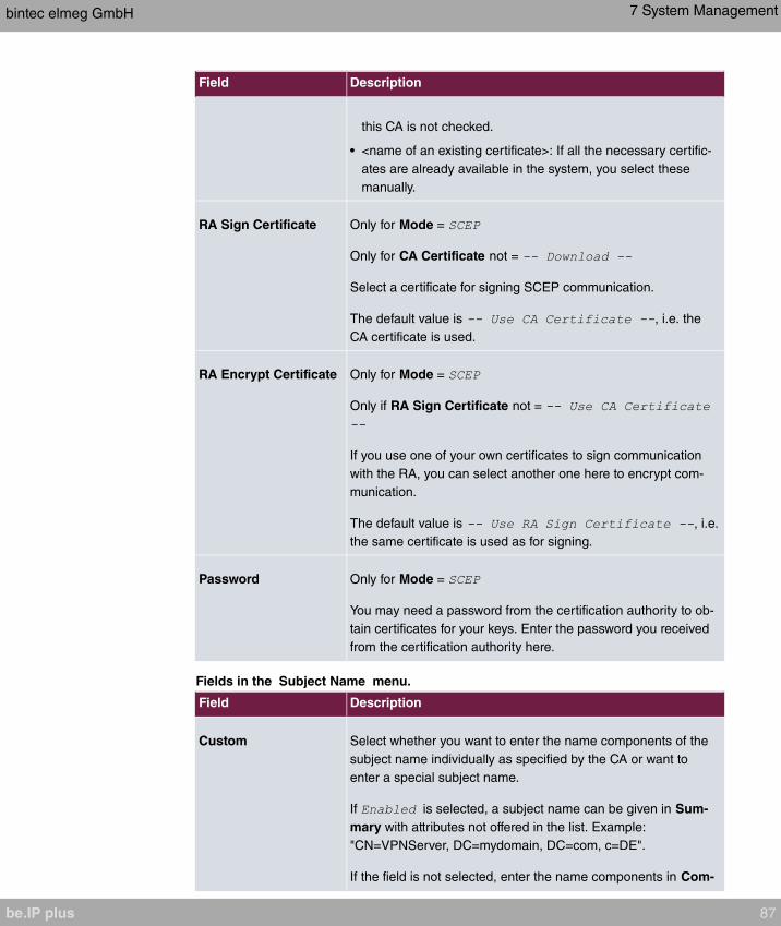
Field Description
this CA is not checked.
• <name of an existing certificate>: If all the necessary certific-
ates are already available in the system, you select these
manually.
RA Sign Certificate Only for Mode =
Only for CA Certificate not =
Select a certificate for signing SCEP communication.
The default value is , i.e. the
CA certificate is used.
RA Encrypt Certificate Only for Mode =
Only if RA Sign Certificate not =
If you use one of your own certificates to sign communication
with the RA, you can select another one here to encrypt com-
munication.
The default value is , i.e.
the same certificate is used as for signing.
Password Only for Mode =
You may need a password from the certification authority to ob-
tain certificates for your keys. Enter the password you received
from the certification authority here.
Fields in the Subject Name menu.
Field Description
Custom Select whether you want to enter the name components of the
subject name individually as specified by the CA or want to
enter a special subject name.
If is selected, a subject name can be given in Sum-
mary with attributes not offered in the list. Example:
"CN=VPNServer, DC=mydomain, DC=com, c=DE".
If the field is not selected, enter the name components in Com-
bintec elmeg GmbH 7 System Management
be.IP plus 87
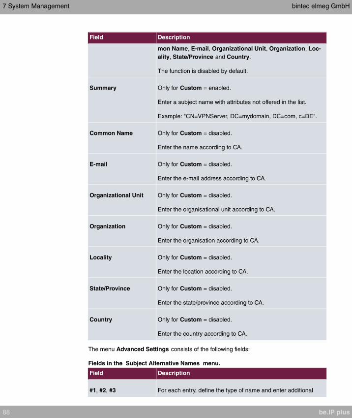
Field Description
mon Name, E-mail, Organizational Unit, Organization, Loc-
ality, State/Province and Country.
The function is disabled by default.
Summary Only for Custom = enabled.
Enter a subject name with attributes not offered in the list.
Example: "CN=VPNServer, DC=mydomain, DC=com, c=DE".
Common Name Only for Custom = disabled.
Enter the name according to CA.
E-mail Only for Custom = disabled.
Enter the e-mail address according to CA.
Organizational Unit Only for Custom = disabled.
Enter the organisational unit according to CA.
Organization Only for Custom = disabled.
Enter the organisation according to CA.
Locality Only for Custom = disabled.
Enter the location according to CA.
State/Province Only for Custom = disabled.
Enter the state/province according to CA.
Country Only for Custom = disabled.
Enter the country according to CA.
The menu Advanced Settings consists of the following fields:
Fields in the Subject Alternative Names menu.
Field Description
#1, #2, #3 For each entry, define the type of name and enter additional
7 System Management bintec elmeg GmbH
88 be.IP plus
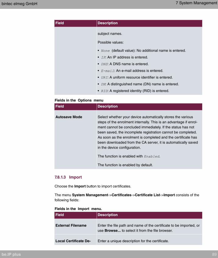
Field Description
subject names.
Possible values:
• (default value): No additional name is entered.
• : An IP address is entered.
• : A DNS name is entered.
• : An e-mail address is entered.
• : A uniform resource identifier is entered.
• : A distinguished name (DN) name is entered.
• : A registered identity (RID) is entered.
Fields in the Options menu
Field Description
Autosave Mode Select whether your device automatically stores the various
steps of the enrolment internally. This is an advantage if enrol-
ment cannot be concluded immediately. If the status has not
been saved, the incomplete registration cannot be completed.
As soon as the enrolment is completed and the certificate has
been downloaded from the CA server, it is automatically saved
in the device configuration.
The function is enabled with .
The function is enabled by default.
7.8.1.3 Import
Choose the Import button to import certificates.
The menu System Management->Certificates->Certificate List->Import consists of the
following fields:
Fields in the Import menu.
Field Description
External Filename Enter the file path and name of the certificate to be imported, or
use Browse... to select it from the file browser.
Local Certificate De- Enter a unique description for the certificate.
bintec elmeg GmbH 7 System Management
be.IP plus 89

Field Description
scription
File Encoding Select the type of coding so that your device can decode the
certificate.
Possible values:
• (default value): Activates automatic code recognition. If
downloading the certificate in auto mode fails, try with a cer-
tain type of encoding.
•
•
Password You may need a password to obtain certificates for your keys.
Enter the password here.
7.8.2 CRLs
In the System Management->Certificates->CRLs menu, a list of all CRLs (Certification
Revocation List) is displayed.
If a key is no longer to be used, e.g. because it has fallen into the wrong hands or has been
lost, the corresponding certificate is declared invalid. The certification authority revokes the
certificate and publishes it on a certificate blacklist, so-called CRL. Certificate users should
always check against these lists to ensure that the certificate used is currently valid. This
check can be automated via a browser.
The Simple Certificate Enrollment Protocol (SCEP) supports the issue and revocation of
certificates in networks.
7.8.2.1 Import
Choose the Import button to import CRLs.
The System Management->Certificates->CRLs->Import menu consists of the following
fields:
Fields in the CRL Import menu.
Field Description
External Filename Enter the file path and name of the CRL to be imported, or use
Browse... to select it from the file browser.
7 System Management bintec elmeg GmbH
90 be.IP plus

Field Description
Local Certificate De-
scription
Enter a unique description for the CRL.
File Encoding Select the type of encoding, so that your device can decode the
CRL.
Possible values:
• (default value): Activates automatic code recognition. If
downloading the CRL in auto mode fails, try with a certain
type of encoding.
•
•
Password Enter the password required for the import.
7.8.3 Certificate Servers
A list of certificate servers is displayed in the System Management->Certificates->Certi-
ficate Servers menu.
A certification authority (certification service provider, Certificate Authority, CA) issues your
certificates to clients applying for a certificate via a certificate server. The certificate server
also issues the private key and provides certificate revocation lists (CRL) that are accessed
by the device via LDAP or HTTP in order to verify certificates.
7.8.3.1 New
Choose the New button to set up a certificate server.
The System Management->Certificates->Certificate Servers->New menu consists of
the following fields:
Fields in the Basic Parameters menu.
Field Description
Description Enter a unique description for the certificate server.
LDAP URL Path Enter the LDAP URL or the HTTP URL of the server.
bintec elmeg GmbH 7 System Management
be.IP plus 91
Chapter 8 Physical Interfaces
In this menu, you configure the physical interfaces that you have used when connecting
your gateway. The configuration interface only shows the interfaces that are available on
your device. In the System Management->Status menu, you can see a list of all physical
interfaces and information on whether the interfaces are connected or active and whether
they have already been configured.
8.1 Ethernet Ports
An Ethernet interface is a physical interface for connection to the local network or external
networks.
The Ethernet ports ETH1 to ETH4 are assigned to a single logical Ethernet interface in ex
works state. The logical Ethernet interface is assigned and is preconfigured with the
IP Address and Netmask .
Note
To ensure your system can be reached, when splitting ports make sure that Ethernet
interface with the preconfigured IP address and netmask is assigned to a port
that can be reached via Ethernet. If in doubt, carry out the configuration using a serial
connection via the Serial 1 interface.
ETH1 - ETH4
The interfaces can be used separately. They are logically separated from each other, each
separated port is assigned the desired logical Ethernet interface in the Ethernet Interface
Selection field of the Port Configuration menu. For each assigned Ethernet interface, an-
other interface is displayed in the list in the LAN->IP Configuration menu, and the inter-
face can be confugred completely independently.
VLANs for Routing Interfaces
Configure VLANs to separate individual network segments from each other, for example
(e.g. individual departments of a company) or to reserve bandwidth for individual VLANs
when managed switches are used with the QoS function.
8 Physical Interfaces bintec elmeg GmbH
92 be.IP plus
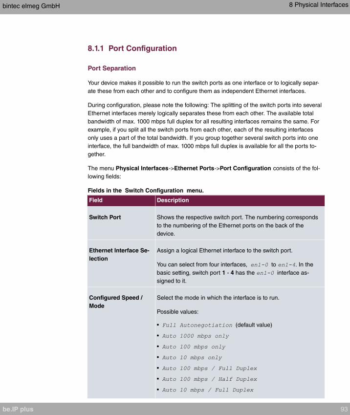
8.1.1 Port Configuration
Port Separation
Your device makes it possible to run the switch ports as one interface or to logically separ-
ate these from each other and to configure them as independent Ethernet interfaces.
During configuration, please note the following: The splitting of the switch ports into several
Ethernet interfaces merely logically separates these from each other. The available total
bandwidth of max. 1000 mbps full duplex for all resulting interfaces remains the same. For
example, if you split all the switch ports from each other, each of the resulting interfaces
only uses a part of the total bandwidth. If you group together several switch ports into one
interface, the full bandwidth of max. 1000 mbps full duplex is available for all the ports to-
gether.
The menu Physical Interfaces->Ethernet Ports->Port Configuration consists of the fol-
lowing fields:
Fields in the Switch Configuration menu.
Field Description
Switch Port Shows the respective switch port. The numbering corresponds
to the numbering of the Ethernet ports on the back of the
device.
Ethernet Interface Se-
lection
Assign a logical Ethernet interface to the switch port.
You can select from four interfaces, to . In the
basic setting, switch port 1 - 4 has the interface as-
signed to it.
Configured Speed /
Mode
Select the mode in which the interface is to run.
Possible values:
• (default value)
•
•
•
•
•
•
bintec elmeg GmbH 8 Physical Interfaces
be.IP plus 93
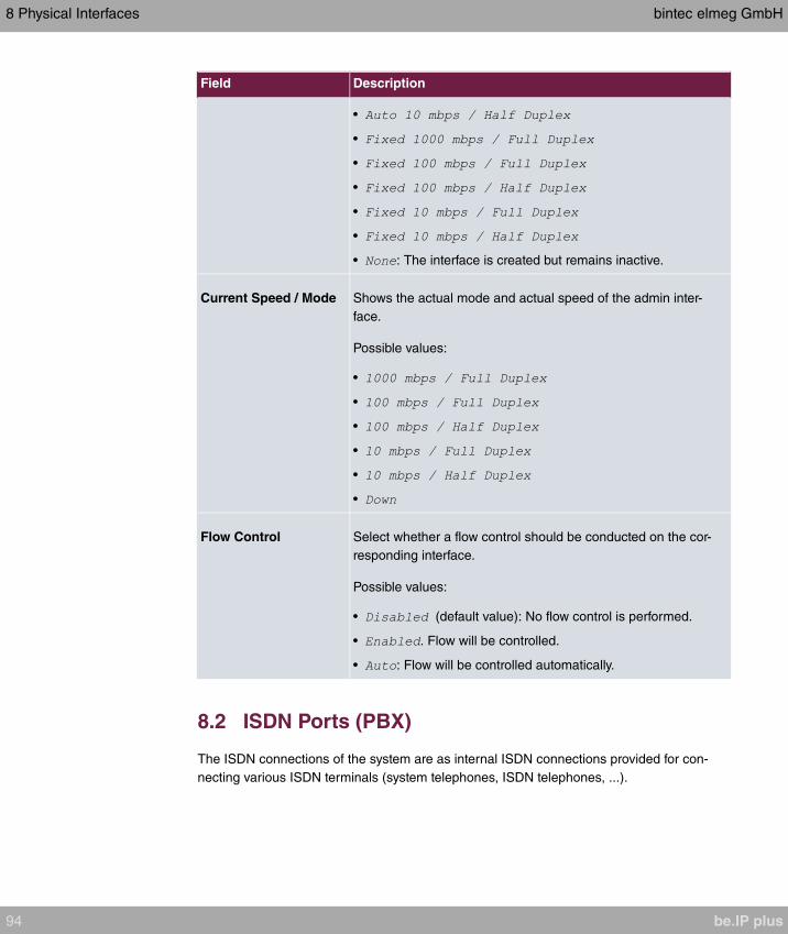
Field Description
•
•
•
•
•
•
• : The interface is created but remains inactive.
Current Speed / Mode Shows the actual mode and actual speed of the admin inter-
face.
Possible values:
•
•
•
•
•
•
Flow Control Select whether a flow control should be conducted on the cor-
responding interface.
Possible values:
• (default value): No flow control is performed.
• . Flow will be controlled.
• : Flow will be controlled automatically.
8.2 ISDN Ports (PBX)
The ISDN connections of the system are as internal ISDN connections provided for con-
necting various ISDN terminals (system telephones, ISDN telephones, ...).
8 Physical Interfaces bintec elmeg GmbH
94 be.IP plus
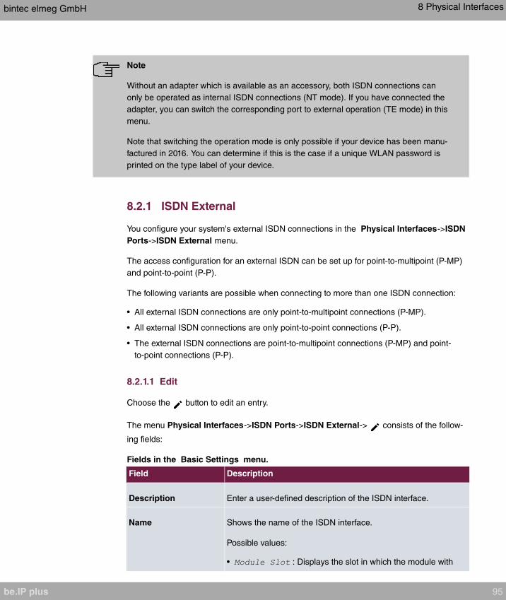
Note
Without an adapter which is available as an accessory, both ISDN connections can
only be operated as internal ISDN connections (NT mode). If you have connected the
adapter, you can switch the corresponding port to external operation (TE mode) in this
menu.
Note that switching the operation mode is only possible if your device has been manu-
factured in 2016. You can determine if this is the case if a unique WLAN password is
printed on the type label of your device.
8.2.1 ISDN External
You configure your system's external ISDN connections in the Physical Interfaces->ISDN
Ports->ISDN External menu.
The access configuration for an external ISDN can be set up for point-to-multipoint (P-MP)
and point-to-point (P-P).
The following variants are possible when connecting to more than one ISDN connection:
• All external ISDN connections are only point-to-multipoint connections (P-MP).
• All external ISDN connections are only point-to-point connections (P-P).
• The external ISDN connections are point-to-multipoint connections (P-MP) and point-
to-point connections (P-P).
8.2.1.1 Edit
Choose the button to edit an entry.
The menu Physical Interfaces->ISDN Ports->ISDN External-> consists of the follow-
ing fields:
Fields in the Basic Settings menu.
Field Description
Description Enter a user-defined description of the ISDN interface.
Name Shows the name of the ISDN interface.
Possible values:
• : Displays the slot in which the module with
bintec elmeg GmbH 8 Physical Interfaces
be.IP plus 95

Field Description
the ISDN interface is inserted.
• : Displays the port on the module to which the ISDN connec-
tion is connected.
• : 4 wire (S)
Example: = The interface is located
on the module inserted in slot 3 on port 2, and is used as an S
connection.
Access Type Select whether the ISDN interface will be operated as a point-
to-multipoint connection or as a point-to-point connection.
Possible values:
•
•
The menu Advanced Settings consists of the following fields:
Fields in the Advanced Settings menu.
Field Description
Permanent Layer 2 Ac-
tivation
This function (also known as permanent monitoring) constantly
monitors the functionality and transmission quality of an external
ISDN connection. For this purpose, the system is in permanent
contact with your network operator's exchange. If the exchange
does not keep the ISDN layer 2 permanently enabled, the sys-
tem can initiate the repeated establishment of layer 2.
The function is activated by selecting .
The function is disabled by default.
ISDN Synchronisation When an external device (e. g. GSM gateway) is connected to
an external point-to-point ISDN access in the system, the ex-
ternal device's signal can disturb the synchronisation in the
ISDN signal. Only if such a disturbance occurs should you
switch off the layer 1 synchronisation.
The function is activated by selecting .
The function is enabled by default.
8 Physical Interfaces bintec elmeg GmbH
96 be.IP plus
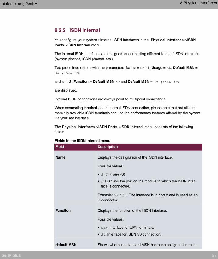
8.2.2 ISDN Internal
You configure your system's internal ISDN interfaces in the Physical Interfaces->ISDN
Ports->ISDN Internal menu.
The internal ISDN interfaces are designed for connecting different kinds of ISDN terminals
(system phones, ISDN phones, etc.)
Two predefined entries with the parameters Name = 1, Usage = , Default MSN =
and 2, Function = Default MSN and Default MSN =
are displayed.
Internal ISDN connections are always point-to-multipoint connections
When connecting terminals to an internal ISDN connection, please note that not all com-
mercially available ISDN terminals can use the performance features offered by the system
via your key interface.
The Physical Interfaces->ISDN Ports->ISDN Internal menu consists of the following
fields:
Fields in the ISDN Internal menu
Field Description
Name Displays the designation of the ISDN interface.
Possible values:
• : 4 wire (S)
• : Displays the port on the module to which the ISDN inter-
face is connected.
Example: = The interface is in port 2 and is used as an
S-connector.
Function Displays the function of the ISDN interface.
Possible values:
• : Interface for UPN terminals.
• : Interface for ISDN S0 connection.
default MSN Shows whether a standard MSN has been assigned for an in-
bintec elmeg GmbH 8 Physical Interfaces
be.IP plus 97
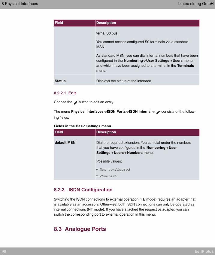
Field Description
ternal S0 bus.
You cannot access configured S0 terminals via a standard
MSN.
As standard MSN, you can dial internal numbers that have been
configured in the Numbering->User Settings->Users menu
and which have been assigned to a terminal in the Terminals
menu.
Status Displays the status of the interface.
8.2.2.1 Edit
Choose the button to edit an entry.
The menu Physical Interfaces->ISDN Ports->ISDN Internal-> consists of the follow-
ing fields:
Fields in the Basic Settings menu
Field Description
default MSN Dial the required extension. You can dial under the numbers
that you have configured in the Numbering->User
Settings->Users->Numbers menu.
Possible values:
•
•
8.2.3 ISDN Configuration
Switching the ISDN connections to external operation (TE mode) requires an adapter that
is available as an accessory. Otherwise, both ISDN connections can only be operated as
internal connections (NT mode). If you have attached the respective adapter, you can
switch the corresponding port to external operation in this menu.
8.3 Analogue Ports
8 Physical Interfaces bintec elmeg GmbH
98 be.IP plus
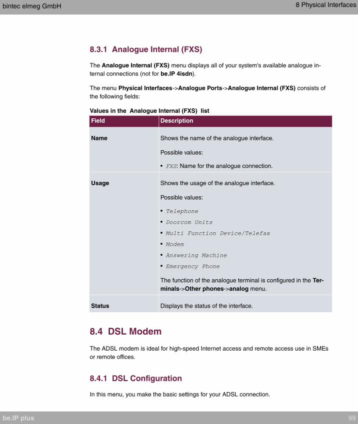
8.3.1 Analogue Internal (FXS)
The Analogue Internal (FXS) menu displays all of your system's available analogue in-
ternal connections (not for be.IP 4isdn).
The menu Physical Interfaces->Analogue Ports->Analogue Internal (FXS) consists of
the following fields:
Values in the Analogue Internal (FXS) list
Field Description
Name Shows the name of the analogue interface.
Possible values:
• : Name for the analogue connection.
Usage Shows the usage of the analogue interface.
Possible values:
•
•
•
•
•
•
The function of the analogue terminal is configured in the Ter-
minals->Other phones->analog menu.
Status Displays the status of the interface.
8.4 DSL Modem
The ADSL modem is ideal for high-speed Internet access and remote access use in SMEs
or remote offices.
8.4.1 DSL Configuration
In this menu, you make the basic settings for your ADSL connection.
bintec elmeg GmbH 8 Physical Interfaces
be.IP plus 99
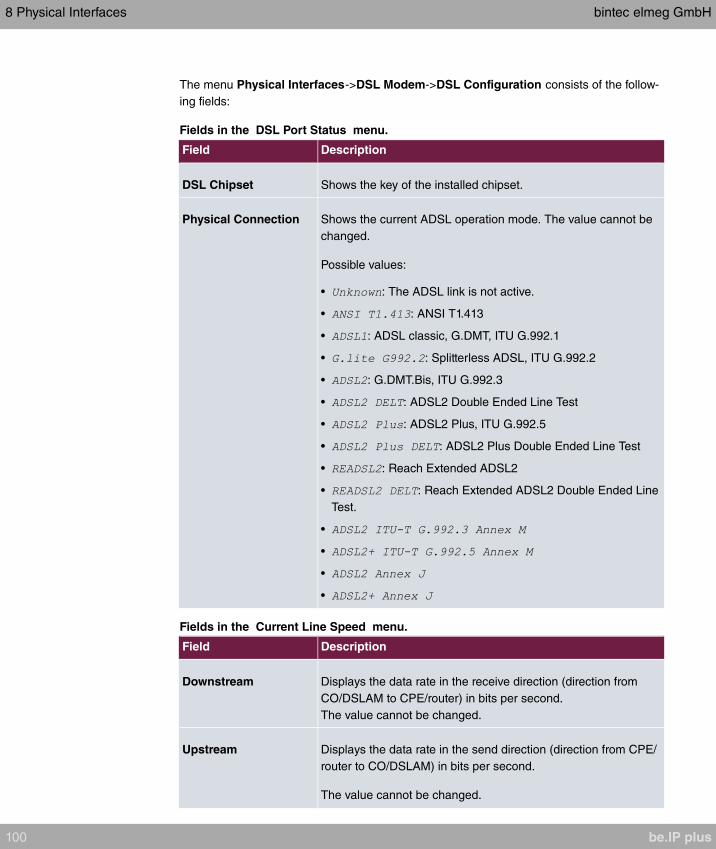
The menu Physical Interfaces->DSL Modem->DSL Configuration consists of the follow-
ing fields:
Fields in the DSL Port Status menu.
Field Description
DSL Chipset Shows the key of the installed chipset.
Physical Connection Shows the current ADSL operation mode. The value cannot be
changed.
Possible values:
• : The ADSL link is not active.
• : ANSI T1.413
• : ADSL classic, G.DMT, ITU G.992.1
• : Splitterless ADSL, ITU G.992.2
• : G.DMT.Bis, ITU G.992.3
• : ADSL2 Double Ended Line Test
• : ADSL2 Plus, ITU G.992.5
• : ADSL2 Plus Double Ended Line Test
• : Reach Extended ADSL2
• : Reach Extended ADSL2 Double Ended Line
Test.
•
•
•
•
Fields in the Current Line Speed menu.
Field Description
Downstream Displays the data rate in the receive direction (direction from
CO/DSLAM to CPE/router) in bits per second.
The value cannot be changed.
Upstream Displays the data rate in the send direction (direction from CPE/
router to CO/DSLAM) in bits per second.
The value cannot be changed.
8 Physical Interfaces bintec elmeg GmbH
100 be.IP plus
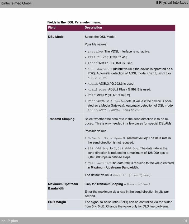
Fields in the DSL Parameter menu.
Field Description
DSL Mode Select the DSL Mode.
Possible values:
• : The VDSL interface is not active.
• : ETSI T1.413
• :ADSL1 / G.DMT is used.
• (default value if the device is operated as a
PBX): Automatic detection of ADSL mode , or
• : ADSL2 / G.992.3 is used.
• : ADSL2 Plus / G.992.5 is used.
• : VDSL2 (ITU-T G.993.2)
• (default value if the device is oper-
ated as a Media Gateway): Automatic detection of DSL mode
, , or
Transmit Shaping Select whether the data rate in the send direction is to be re-
duced. This is only needed in a few cases for special DSLAMs.
Possible values:
• (default value): The data rate in
the send direction is not reduced.
• to : The data rate in the
send direction is reduced to a maximum of 128,000 bps to
2,048,000 bps in defined steps.
• :The data rate is reduced to the value entered
in Maximum Upstream Bandwidth.
The default value is .
Maximum Upstream
Bandwidth
Only for Transmit Shaping =
Enter the maximum data rate in the send direction in bits per
second.
SNR Margin The signal-to-noise ratio (SNR) can be controlled via the slider
from 0 to 5 dB. Change the value only for DLS line problems.
bintec elmeg GmbH 8 Physical Interfaces
be.IP plus 101

The menu Advanced Settings consists of the following fields:
Fields in the Advanced Settings menu.
Field Description
DSL Line Profile Select the internet service provider you require and, in doing so,
implicitly select the modem parameter set used by this provider.
is entered as the default value.
If your provider is not shown in the list, use the set-
ting.
8.5 UMTS/LTE
8.5.1 UMTS/LTE
In the UMTS/LTE menu, configure the connection for the integrated UMTS/HSDPA/LTE
modem (depending on the configuration of your device) or an optional pluggable UMTS/
LTE USB stick.
A list of compatible UMTS/LTE USB sticks can be found at www.bintec-elmeg.com under
Products.
Note
If you are connecting to the internet via UMTS and are using the SMS alert service, the
connection is briefly interrupted when an SMS is sent.
Note
LTE cannot currently be used for incoming connections via ISDN login.
LTE cannot currently be used together with the SMS alert service.
8.5.1.1 Edit
Click the icon to edit the respective entry for the integrated modem or a plugged UMTS/
LTE USB stick.
8 Physical Interfaces bintec elmeg GmbH
102 be.IP plus

Select the following entry for the corresponding UMTS/LTE modem:
• : The integrated modem is to be configured.
• : The plug-in UMTS USB stick is to be configured.
Note
Please note that the technology used not only depends on availability and the setting
in the Preferred Network Type field; rather it is also determined by the strength and
quality of the signal.
The menu Physical Interfaces->UMTS/LTE->UMTS/LTE-> consists of the following
fields:
Fields in the Basic Settings menu.
Field Description
UMTS/LTE Status Select whether the chosen UMTS/LTE modem should be en-
abled or disabled.
The function is enabled with .
The function is enabled by default.
Modem Status Only for UMTS/LTE Status =
Shows the status of the UMTS/LTE modem.
Possible values:
•
•
•
•
•
•
•
•
•
•
bintec elmeg GmbH 8 Physical Interfaces
be.IP plus 103
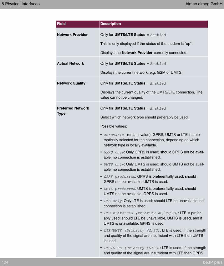
Field Description
Network Provider Only for UMTS/LTE Status =
This is only displayed if the status of the modem is "up".
Displays the Network Provider currently connected.
Actual Network Only for UMTS/LTE Status =
Displays the current network, e.g. GSM or UMTS.
Network Quality Only for UMTS/LTE Status =
Displays the current quality of the UMTS/LTE connection. The
value cannot be changed.
Preferred Network
Type
Only for UMTS/LTE Status =
Select which network type should preferably be used.
Possible values:
• (default value): GPRS, UMTS or LTE is auto-
matically selected for the connection, depending on which
network type is locally available.
• : Only GPRS is used; should GPRS not be avail-
able, no connection is established.
• : Only UMTS is used; should UMTS not be avail-
able, no connection is established.
• : GPRS is preferentially used; should
GPRS not be available, UMTS is used.
• : UMTS is preferentially used; should
UMTS not be available, GPRS is used.
• : Only LTE is used; should LTE be unavailable, no
connection is established.
• : LTE is prefer-
ably used; should LTE be unavailable, UMTS is used, and if
UMTS is unavailable, GPRS is used.
• : LTE is used. If the strength
and quality of the signal are insufficient with LTE then UMTS
is used.
• : LTE is used. If the strength
and quality of the signal are insufficient with LTE then GPRS
8 Physical Interfaces bintec elmeg GmbH
104 be.IP plus
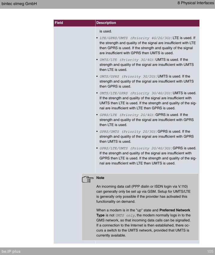
Field Description
is used.
• : LTE is used. If
the strength and quality of the signal are insufficient with LTE
then GPRS is used. If the strength and quality of the signal
are insufficient with GPRS then UMTS is used.
• : UMTS is used. If the
strength and quality of the signal are insufficient with UMTS
then LTE is used.
• : UMTS is used. If the
strength and quality of the signal are insufficient with UMTS
then GPRS is used.
• : UMTS is used.
If the strength and quality of the signal are insufficient with
UMTS then LTE is used. If the strength and quality of the sig-
nal are insufficient with LTE then GPRS is used.
• : GPRS is used. If the
strength and quality of the signal are insufficient with GPRS
then LTE is used.
• : GPRS is used. If the
strength and quality of the signal are insufficient with GPRS
then UMTS is used.
• : GPRS is used.
If the strength and quality of the signal are insufficient with
GPRS then LTE is used. If the strength and quality of the sig-
nal are insufficient with LTE then UMTS is used.
Note
An incoming data call (PPP dialin or ISDN login via V.110)
can generally only be set up via GSM. Setup for UMTS/LTE
is generally only possible if the provider has activated this
functionality on demand.
When a modem is in the "up" state and Preferred Network
Type is not , the modem normally logs in to the
GMS network, so that incoming data calls can be signalled.
If a connection to the Internet is then established, there oc-
curs a switch to the UMTS network, provided that UMTS is
currently available.
bintec elmeg GmbH 8 Physical Interfaces
be.IP plus 105

Field Description
Incoming Service Type Only for UMTS/LTE Status =
Here you select the gateway subsystem to which an incoming
call over the modem is to be assigned.
Possible values:
• : Call is not accepted (default value for LTE con-
nections).
• : The call is assigned to the ISDN Login subsys-
tem (default value for UMTS connections).
• : The call is assigned to the PPP subsystem.
• : The call is made via IPSec.
Please note the following for the setting Incoming Service
Type :
IPSec callback is used to cause an IPSec peer to set up an In-
ternet connection, thus allowing an IPSec tunnel over the Inter-
net. You can make a direct call via the UMTS/LTE wireless net-
work in order to signal to a peer that you are online and waiting
for an IPSec tunnel to be set up over the Internet. If the called
peer currently has no connection to the Internet, the mobile call
causes a connection to be set up.
In the VPN->IPSec->IPSec Peers-> ->Advanced Settings
menu, you can also choose whether the IP address for IPSec
tunnel setup should be transmitted with the UMTS/LTE callback
call under Transfer own IP address over ISDN/GSM . This
may shorten and simplify tunnel setup.
PUK This is only displayed if the device has made three failed at-
tempts to establish a connection, e.g. if the PIN for the SIM card
(see the SIM Card Uses PIN field) has been entered incorrectly
three times.
Enter the PUK (personal unblocking key) for your SIM card to
unblock the SIM card.
SIM Card Uses PIN Only for UMTS/LTE Status =
Enter the PIN for your UMTS/LTE modem card.
8 Physical Interfaces bintec elmeg GmbH
106 be.IP plus

Field Description
Note
Entering a wrong PIN blocks communication until the entry
is corrected.
Note
If the device has made three failed attempts to establish a
connection, e.g. because the PIN has been entered incor-
rectly three times, you will need to enter the PUK in order
to unblock the SIM card.
Fallback Number Only for UMTS/LTE Status =
Enter the call number for the GSM fallback function.
When a voice calls goes in on this number, any active connec-
tion is immediately disconnected and the operating mode of the
modem reset to GSM, where the modem remains until another
data call (PPP, ISDN login, IPSec callback) comes in. If flat-rate
mode is enabled for the WAN connection (option Always active
enabled in WAN->Internet + Dialup->UMTS/LTE-> ), this
means that the connection will be re-established immediately.
Note
Please note that the SIM card must support this function,
and that not all mobile telephony providers relay voice calls
over data SIM cards.
APN (Access Point
Name)
Only for UMTS/LTE Status =
If GPRS/UMTS/LTE is to be used, you must enter the so-called
Access Point Name that you received from your provider here.
A maximum of 80 characters can be entered.
If no APN or an incorrect APN has been entered, a configured
GPRS/UMTS/LTE connection will not function.
bintec elmeg GmbH 8 Physical Interfaces
be.IP plus 107
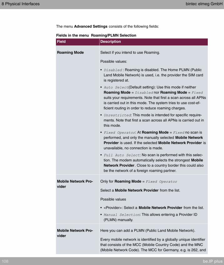
The menu Advanced Settings consists of the following fields:
Fields in the menu Roaming/PLMN Selection
Field Description
Roaming Mode Select if you intend to use Roaming.
Possible values:
• : Roaming is disabled. The Home PLMN (Public
Land Mobile Network) is used, i.e. the provider the SIM card
is registered at.
• (Default setting): Use this mode if neither
Roaming Mode = nor Roaming Mode =
suits your requirements. Note that first a scan across all APNs
is carried out in this mode. The system tries to use cost-ef-
ficient routing in order to reduce roaming charges.
• : This mode is intended for specific require-
ments. Note that first a scan across all APNs is carried out in
this mode.
• : At Roaming Mode = no scan is
performed, and only the manually selected Mobile Network
Provider is used. If the selected Mobile Network Provider is
unavailable, no connection is made.
• : No scan is performed with this selec-
tion. The modem automatically selects the strongest Mobile
Network Provider . Close to a country border this could also
be the network of a foreign roaming partner.
Mobile Network Pro-
vider
Only for Roaming Mode =
Select a Mobile Network Provider from the list.
Possible values
• <Provider>: Select a Mobile Network Provider from the list.
• : This allows entering a Provider ID
(PLMN) manually.
Mobile Network Pro-
vider
Here you can add a PLMN (Public Land Mobile Network).
Every mobile network is identified by a globally unique identifier
that consists of the MCC (Mobile Country Code) and the MNC
(Mobile Network Code). The MCC for Germany, e.g. is 262, and
8 Physical Interfaces bintec elmeg GmbH
108 be.IP plus

Field Description
the MNC for T-Mobile in Germany is 01. This results in the
PLMN .
Fields in the menu Closed User Group
Field Description
Authentication APN Enter the Authentication Access Point Name for the Closed
User Group, that you have received from your provider.
Authentication Method Select an authentication protocol for the Closed User Group.
Select only an authentication method that has been specified by
your provider.
Possible values:
• : Some providers do not use authentication. Select this
option if your provider is among them.
• : Execute only PAP (PPP Password Authentication Pro-
tocol), the password is sent unenctypted.
• : Execute only CHAP (PPP Challenge Handshake Au-
thentication Protocol according to RFC 1994) the password is
sent encrypted.
• (Default value): Prefer CHAP, use PAP if not avail-
able.
Username Enter the user name that has been supplied by your provider.
Password Enter the password that has been supplied by your provider.
Fixed IP Address Enter the Ip address that has been supplied by your provider.
Clicking the button opens a page with detailed statistics on the current UMTS/LTE con-
nection.
Values in the list Mobile Device Status
Field Description
Device Displays the description of the internal modem port.
Modem Model Displays the modem model description.
IMEI The IMEI (International Mobile Station Equipment Identity) dis-
plays the 15 digit serial number of the modem.
Oper Status Displays the operation mode of the modem.
bintec elmeg GmbH 8 Physical Interfaces
be.IP plus 109

Field Description
ICC ID Displays the card ID stored on the SIM card.
Subscriber Number Displays the calling number stored on the SIM card.
Service Center Ad-
dress
Displays the address of the provider's service center stored on
the SIM card.
Home PLMN Displays the Home PLMN (Public Land Mobile Network), i.e. the
provider the SIM card is registered at.
Selected PLMN Displays the selected PLMN. If no PLMN is selected, the Home
PLNM is displayed.
Actual Network Displays which kind of network is currently used (e.g., UMTS or
GPRS).
Network Quality Displays the current connection quality.
Location Area Code Displays the radio cell code of the cell the modem is currently
connected to.
Cell ID Displays the Cell ID of the cell the modem is currently registered
in.
Last Command Displays the last command sent to the modem by the system.
Last Reply Displays the last reply sent by the modem.
Values in the list Mobile Operators
Field Description
PLMN Displays the PLMN of the carrier.
Name Displays the name of the carrier.
Access Type Displays the currently available network type (e.g., UMTS oder
GSM).
State Displays the registration status.
8 Physical Interfaces bintec elmeg GmbH
110 be.IP plus
Chapter 9 VoIP (PABX)
Voice over IP (VoIP) uses the IP protocol for voice and video transmission.
The main difference compared with conventional telephony is that the voice information is
not transmitted over a switched connection in a telephone network, but divided into data
packets by the Internet protocol and these packets are then passed to the destination over
undefined paths in a network. This technology uses the existing network infrastructure for
voice transmission and shares this with other communication services.
9.1 Settings
You set up your VoIP connections in the VoIP->Settings menu.
You can telephone over the internet using all internally connected telephones. The number
of connections depends on various parameters:
• The availability of the system's free channels.
• The available bandwidth of the DSL connection.
• The configured, available SIP providers.
• The SIP-out licenses that have been entered.
9.1.1 SIP Provider
You configure the SIP provider you want in the VoIP->Settings->SIP Provider menu.
You change the status of the SIP provider by pressing the button or the button in the
Action column.
After about one minute, registration with the provider has taken place and the status is
automatically set to (active).
9.1.1.1 Edit or New
Choose the icon to edit existing entries. Select the New button to create new entries.
The menu VoIP->Settings->SIP Provider->New consists of the following fields:
Fields in the Basic Settings menu.
bintec elmeg GmbH 9 VoIP (PABX)
be.IP plus 111

Field Description
Description You can enter a name for the SIP provider. A 20 digit alpha-
numeric sequence is possible.
Provider Status Select whether this VoIP provider entry is enabled ( ,
default value) or not ( ).
Access Type Select which type of VoIP phonenumbers you wish to configure.
Possible values:
• (default value): Enter the individual
DSL phonenumbers.
• : Enter a basic number in conjunction with
an extension number block.
Authentication ID Enter your provider's authentication ID. A 64 digit alpha-numeric
sequence is possible.
PasswordAt this point, you can assign a password. A 64 digit alpha-nu-
meric sequence is possible.
User Name Enter the user name you received from your VoIP provider. A
64 digit alpha-numeric sequence is possible.
Domain / Realm Enter a new domain name or a new IP address for the SIP
proxy server.
If you do not make an entry, the entry in the Registrar field is
used.
Note: Enter a name or IP address only if this is explicitly spe-
cified by the provider.
Fields in the Outgoing Signalisation Settings menu.
Field Description
Outgoing Signalisation Select the signal you want for outgoing calls.
Possible values:
• (default value)
•
•
9 VoIP (PABX) bintec elmeg GmbH
112 be.IP plus
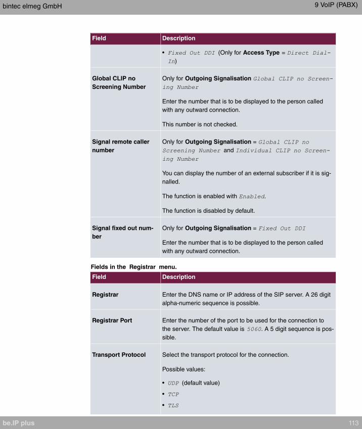
Field Description
• (Only for Access Type =
)
Global CLIP no
Screening Number
Only for Outgoing Signalisation
Enter the number that is to be displayed to the person called
with any outward connection.
This number is not checked.
Signal remote caller
number
Only for Outgoing Signalisation =
and
You can display the number of an external subscriber if it is sig-
nalled.
The function is enabled with .
The function is disabled by default.
Signal fixed out num-
ber
Only for Outgoing Signalisation =
Enter the number that is to be displayed to the person called
with any outward connection.
Fields in the Registrar menu.
Field Description
Registrar Enter the DNS name or IP address of the SIP server. A 26 digit
alpha-numeric sequence is possible.
Registrar Port Enter the number of the port to be used for the connection to
the server. The default value is . A 5 digit sequence is pos-
sible.
Transport Protocol Select the transport protocol for the connection.
Possible values:
• (default value)
•
•
bintec elmeg GmbH 9 VoIP (PABX)
be.IP plus 113
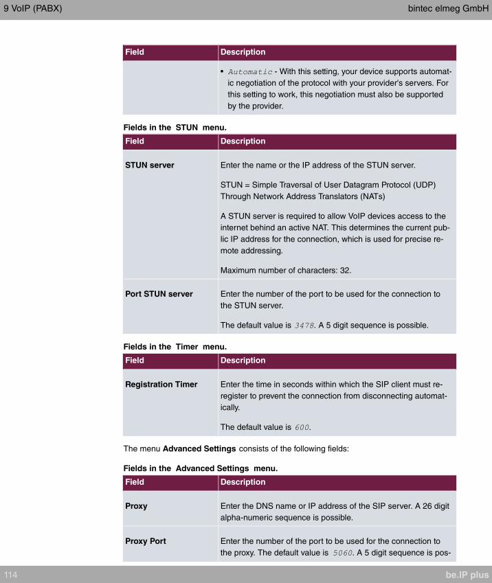
Field Description
• - With this setting, your device supports automat-
ic negotiation of the protocol with your provider's servers. For
this setting to work, this negotiation must also be supported
by the provider.
Fields in the STUN menu.
Field Description
STUN server Enter the name or the IP address of the STUN server.
STUN = Simple Traversal of User Datagram Protocol (UDP)
Through Network Address Translators (NATs)
A STUN server is required to allow VoIP devices access to the
internet behind an active NAT. This determines the current pub-
lic IP address for the connection, which is used for precise re-
mote addressing.
Maximum number of characters: 32.
Port STUN server Enter the number of the port to be used for the connection to
the STUN server.
The default value is . A 5 digit sequence is possible.
Fields in the Timer menu.
Field Description
Registration Timer Enter the time in seconds within which the SIP client must re-
register to prevent the connection from disconnecting automat-
ically.
The default value is .
The menu Advanced Settings consists of the following fields:
Fields in the Advanced Settings menu.
Field Description
Proxy Enter the DNS name or IP address of the SIP server. A 26 digit
alpha-numeric sequence is possible.
Proxy Port Enter the number of the port to be used for the connection to
the proxy. The default value is . A 5 digit sequence is pos-
9 VoIP (PABX) bintec elmeg GmbH
114 be.IP plus

Field Description
sible.
Transport Protocol Select the transport protocol for the connection.
Possible values:
• (default value)
•
•
• - With this setting, your device supports automat-
ic negotiation of the protocol with your provider's servers. For
this setting to work, this negotiation must also be supported
by the provider.
Fields in the Further Settings menu
Field Description
From Domain Enter the SIP provider's "From Domain". It is used after the @
as sender data in the SIP header of the SIP data packages.
Number of allowed
simultaneous Calls
Select the maximum number of calls that shall be simultan-
eously possible Please also note the settings for bandwidth
management here.
Possible values:
• (default value): An unlimited number of sim-
ultaneous calls is possible.
•
•
•
•
•
•
Location Select the location of the SIP server. Locations are defined in
the VoIP->Settings->Locations menu.
Possible values:
• (default value): The server is not operated at
any defined location.
bintec elmeg GmbH 9 VoIP (PABX)
be.IP plus 115
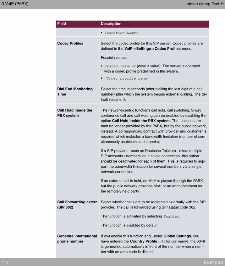
Field Description
•
Codec Profiles Select the codec profile for this SIP server. Codec profiles are
defined in the VoIP->Settings->Codec Profiles menu.
Possible values:
• (default value): The server is operated
with a codec profile predefined in the system.
•
Dial End Monitoring
Time
Select the time in seconds (after dialling the last digit of a call
number) after which the system begins external dialling. The de-
fault value is .
Call Hold inside the
PBX system
The network-centric functions call hold, call switching, 3-way
conference call and call waiting can be enabled by disabling the
option Call Hold inside the PBX system. The functions are
then no longer provided by the PABX, but by the public network,
instead. A corresponding contract with provider and customer is
required which incluides a bandwidth limitation (number of sim-
ultaneously usable voice channels).
If a SIP provider - such as Deutsche Telekom - offers multiple
SIP accounts / numbers via a single connection, this option
should be deactivated for each of them. This is required to sup-
port the bandwidth limitation for several numbers via a single
network connection.
If an external call is held, no MoH is played through the PABX,
but the public network provides MoH or an announcement for
the remotely held party.
Call Forwarding extern
(SIP 302)
Select whether calls are to be redirected externally with the SIP
provider. The call is forwarded using SIP status code 302.
The function is activated by selecting .
The function is disabled by default.
Generate international
phone number
If you enable this function and, under Global Settings, you
have entered the Country Profile ( for Germany), the 0049
is generated automatically in front of the number when a num-
ber with an area code is dialled.
9 VoIP (PABX) bintec elmeg GmbH
116 be.IP plus
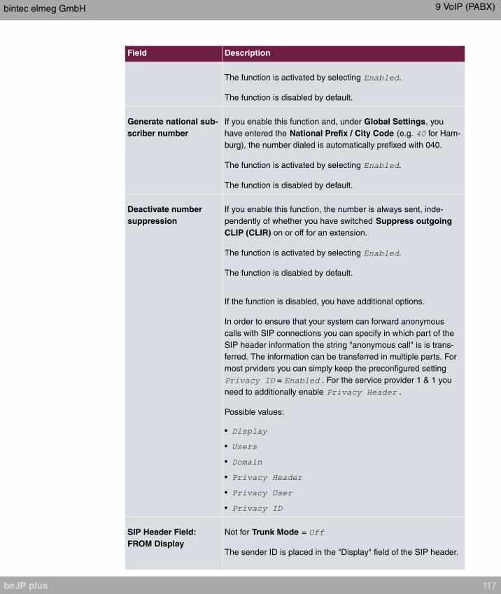
Field Description
The function is activated by selecting .
The function is disabled by default.
Generate national sub-
scriber number
If you enable this function and, under Global Settings, you
have entered the National Prefix / City Code (e.g. for Ham-
burg), the number dialed is automatically prefixed with 040.
The function is activated by selecting .
The function is disabled by default.
Deactivate number
suppression
If you enable this function, the number is always sent, inde-
pendently of whether you have switched Suppress outgoing
CLIP (CLIR) on or off for an extension.
The function is activated by selecting .
The function is disabled by default.
If the function is disabled, you have additional options.
In order to ensure that your system can forward anonymous
calls with SIP connections you can specify in which part of the
SIP header information the string "anonymous call" is is trans-
ferred. The information can be transferred in multiple parts. For
most prviders you can simply keep the preconfigured setting
= . For the service provider 1 & 1 you
need to additionally enable .
Possible values:
•
•
•
•
•
•
SIP Header Field:
FROM Display
Not for Trunk Mode =
The sender ID is placed in the "Display" field of the SIP header.
bintec elmeg GmbH 9 VoIP (PABX)
be.IP plus 117

Field Description
Possible values:
• (default value): The sender ID is not sent.
• : The user-configured user name is displayed.
• : The user-configured number the called
party is displayed.
• : The actual phone number from which the
calls is initiated (e.g. for billing purposes) is displayed.
SIP Header Field:
FROM User
Not for Trunk Mode =
The sender ID is sent in the "User" field of the SIP header.
Possible values:
• (default value): The user-configured user name is
displayed.
• : The user-configured number the called
party is displayed.
• : The actual phone number from which the
calls is initiated (e.g. for billing purposes) is displayed.
SIP Header Field: P-
Preferred
Not for Trunk Mode =
The so-called "p-preferred-identity" field is added to the SIP
header and contains the sender ID.
Possible values:
• (default value): The sender ID is not sent.
• : The user-configured user name is displayed.
• : The user-configured number the called
party is displayed.
• : The actual phone number from which the
calls is initiated (e.g. for billing purposes) is displayed.
SIP Header Field: P-
Asserted
Not for Trunk Mode =
The so-called "p-asserted-identity" field is added to the SIP
header and contains the sender ID.
Possible values:
9 VoIP (PABX) bintec elmeg GmbH
118 be.IP plus
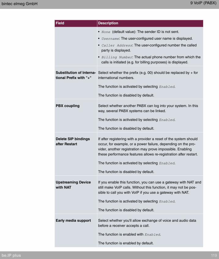
Field Description
• (default value): The sender ID is not sent.
• : The user-configured user name is displayed.
• : The user-configured number the called
party is displayed.
• : The actual phone number from which the
calls is initiated (e.g. for billing purposes) is displayed.
Substitution of Interna-
tional Prefix with "+"
Select whether the prefix (e.g. 00) should be replaced by + for
international numbers.
The function is activated by selecting .
The function is disabled by default.
PBX coupling Select whether another PABX can log into your system. In this
way, several PABX systems can be linked.
The function is activated by selecting .
The function is disabled by default.
Delete SIP bindings
after Restart
If after registering with a provider a reset of the system should
occur, for example, or a power failure, depending on the pro-
vider, another registration may prove impossible. Enabling
these performance features allows re-registration after restart.
The function is activated by selecting .
The function is disabled by default.
Upstreaming Device
with NAT
If you enable this function, you can use a gateway with NAT and
still make VoIP calls. Without this function, it may not be pos-
sible to call you with VoIP if you use a gateway with NAT.
The function is activated by selecting .
The function is disabled by default.
Early media support Select whether you'll allow exchange of voice and audio data
before a receiver accepts a call.
The function is enabled with .
The function is enabled by default.
bintec elmeg GmbH 9 VoIP (PABX)
be.IP plus 119
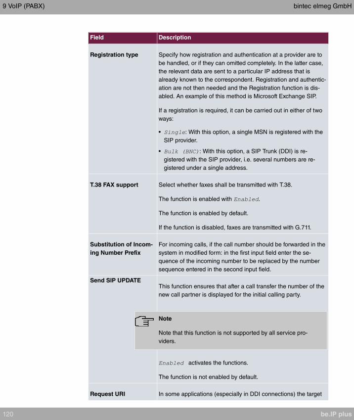
Field Description
Registration type Specify how registration and authentication at a provider are to
be handled, or if they can omitted completely. In the latter case,
the relevant data are sent to a particular IP address that is
already known to the correspondent. Registration and authentic-
ation are not then needed and the Registration function is dis-
abled. An example of this method is Microsoft Exchange SIP.
If a registration is required, it can be carried out in either of two
ways:
• : With this option, a single MSN is registered with the
SIP provider.
• : With this option, a SIP Trunk (DDI) is re-
gistered with the SIP provider, i.e. several numbers are re-
gistered under a single address.
T.38 FAX support Select whether faxes shall be transmitted with T.38.
The function is enabled with .
The function is enabled by default.
If the function is disabled, faxes are transmitted with G.711.
Substitution of Incom-
ing Number Prefix
For incoming calls, if the call number should be forwarded in the
system in modified form: in the first input field enter the se-
quence of the incoming number to be replaced by the number
sequence entered in the second input field.
Send SIP UPDATEThis function ensures that after a call transfer the number of the
new call partner is displayed for the initial calling party.
Note
Note that this function is not supported by all service pro-
viders.
activates the functions.
The function is not enabled by default.
Request URI In some applications (especially in DDI connections) the target
9 VoIP (PABX) bintec elmeg GmbH
120 be.IP plus

Field Description
address of a SIP call needs to be extracted from the Request
URI. By activating this option the address is preferably read
from this field of the invite. The option is not active per default.
Check Source IP As a response to a DNS SRV request, your SIP provider trans-
mits the addresses of valid registration servers. If you activate
this option, each SIP invite has its source IP checked against
these valid addresses. If it does not originate from one of them,
the invite is ignored. The option is not active per default.
TLS certificate check Only for DDI / SIP trunk connections. If a connection is encryp-
ted using TLS (Transport Layer Security) a validity check on the
server certificate of the remote station is performed. The option
is not active per default.
Fields in the Codec Settings menu
Field Description
Codec ProfilesSelect the location of the SIP server. Locations are defined in
the VoIP->Settings->Codec Profiles menu.
Possible values:
• (default value): The server is not operated
at any defined location.
•
Video Select if calls between IP telephones are to support the trans-
mission of video data. Video transmission can only be negoti-
ated between the participants if both support this feature.
SRTP Select if calls via this SIP provider may be secured with SRTP
(Secure Real-Time Transport Protocol).
MediaSec: MediaSec negotiates the protection of RTP data
with the SIP servers.
For seamless support, automatic negotiation of the transport
protocol is mandatory. Fixed transport protocol settings (UDP
and TCP) may cause problems during registration. Additionally,
the use of SRTP must be allowed. Your VoIP provider must
support MediaSec.
bintec elmeg GmbH 9 VoIP (PABX)
be.IP plus 121

9.1.2 Locations
In the VoIP->Settings->Locations menu you configure the locations of the VoIP sub-
scribers who have been configured on your system, and define the bandwidth management
for the VoIP traffic.
Individual locations can be set up for using the bandwidth management. A location is identi-
fied from its fixed IP address or DynDNS address or from the interface to which the device
is connected. The available VoIP bandwidth (up- and downstream) can be set up for each
location.
Only for compact systems: A predefined entry with the parameters Description = ,
Parent Location = , Type = , Interfaces = is displayed.
Fields in the Registration behavior for VoIP subscribers without assigned loca-
tion menu.
Field Description
Default Behavior Specify how the system is to behave when VoIP subscribers for
whom no location has been defined are being registered.
Possible values:
• (default
value): The VoIP subscriber is only registered if they are with-
in the private network.
• : The VoIP subscriber is never registered.
• : The VoIP subscriber is al-
ways registered.
9.1.2.1 Edit or New
Choose the icon to edit existing entries. Select the New button to create new entries.
The menu VoIP->Settings->Locations->New consists of the following fields:
Fields in the Basic Settings menu.
Field Description
Description Enter the description of the entry.
Parent Location You can cascade the SIP locations as you wish. Define here
which SIP location that has been defined constitutes the high-
9 VoIP (PABX) bintec elmeg GmbH
122 be.IP plus
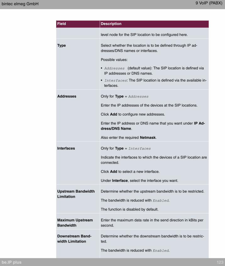
Field Description
level node for the SIP location to be configured here.
Type Select whether the location is to be defined through IP ad-
dresses/DNS names or interfaces.
Possible values:
• (default value): The SIP location is defined via
IP addresses or DNS names.
• : The SIP location is defined via the available in-
terfaces.
Addresses Only for Type =
Enter the IP addresses of the devices at the SIP locations.
Click Add to configure new addresses.
Enter the IP address or DNS name that you want under IP Ad-
dress/DNS Name.
Also enter the required Netmask.
Interfaces Only for Type =
Indicate the interfaces to which the devices of a SIP location are
connected.
Click Add to select a new interface.
Under Interface, select the interface you want.
Upstream Bandwidth
Limitation
Determine whether the upstream bandwidth is to be restricted.
The bandwidth is reduced with .
The function is disabled by default.
Maximum Upstream
Bandwidth
Enter the maximum data rate in the send direction in kBits per
second.
Downstream Band-
width Limitation
Determine whether the downstream bandwidth is to be restric-
ted.
The bandwidth is reduced with .
bintec elmeg GmbH 9 VoIP (PABX)
be.IP plus 123
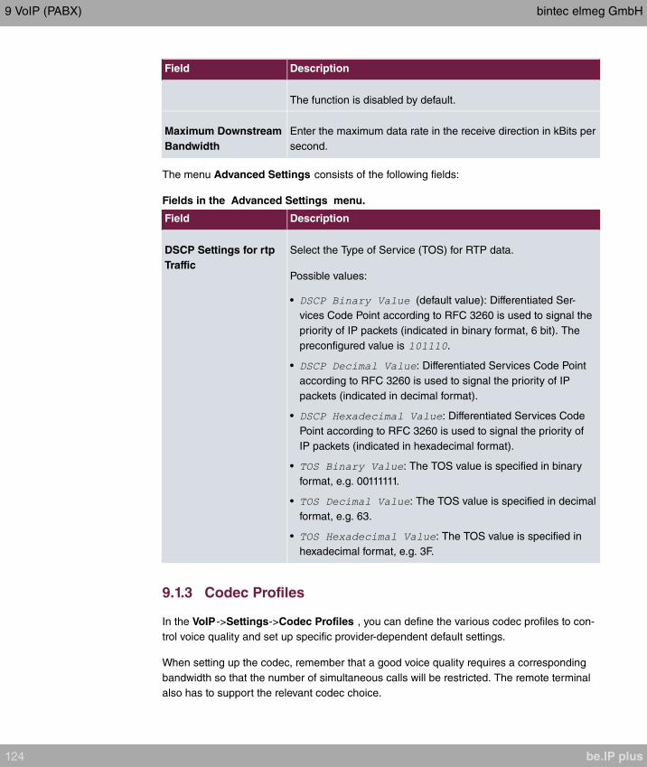
Field Description
The function is disabled by default.
Maximum Downstream
Bandwidth
Enter the maximum data rate in the receive direction in kBits per
second.
The menu Advanced Settings consists of the following fields:
Fields in the Advanced Settings menu.
Field Description
DSCP Settings for rtp
Traffic
Select the Type of Service (TOS) for RTP data.
Possible values:
• (default value): Differentiated Ser-
vices Code Point according to RFC 3260 is used to signal the
priority of IP packets (indicated in binary format, 6 bit). The
preconfigured value is .
• : Differentiated Services Code Point
according to RFC 3260 is used to signal the priority of IP
packets (indicated in decimal format).
• : Differentiated Services Code
Point according to RFC 3260 is used to signal the priority of
IP packets (indicated in hexadecimal format).
• : The TOS value is specified in binary
format, e.g. 00111111.
• : The TOS value is specified in decimal
format, e.g. 63.
• : The TOS value is specified in
hexadecimal format, e.g. 3F.
9.1.3 Codec Profiles
In the VoIP->Settings->Codec Profiles , you can define the various codec profiles to con-
trol voice quality and set up specific provider-dependent default settings.
When setting up the codec, remember that a good voice quality requires a corresponding
bandwidth so that the number of simultaneous calls will be restricted. The remote terminal
also has to support the relevant codec choice.
9 VoIP (PABX) bintec elmeg GmbH
124 be.IP plus

9.1.3.1 Edit or New
Choose the icon to edit existing entries. Select the New button to create new entries.
The menu VoIP->Settings->Codec Profiles->New consists of the following fields:
Fields in the Basic Parameters menu.
Field Description
Description Enter a description for the entry.
Codec Proposal Se-
quence
Choose the order in which the codecs are offered for use by the
system. If the first codec cannot be used, the second is tried
and so on.
Possible values:
• (default value): the codec in the first position in the
menu will be used if possible.
• : The codecs are sorted by quality. The codec with
the best quality is used if possible.
• : The codecs are sorted by required band-
width. If possible, the codec with the lowest bandwidth re-
quirement is used.
• : The codecs are sorted by required band-
width. If possible, the codec with the highest bandwidth re-
quirement is used.
G.711 uLaw Only for Codec Proposal Sequence not
ISDN codec with US characteristic
G.711 uLaw passes audio signals in the range of 300-3500 Hz
and samples them at the rate of 8,000 samples per second. At
64 kbit/s bit rate the mean opinion score (MOS) is 4,4. This au-
dio codec uses µlaw quantization.
G.711 aLaw Only for Codec Proposal Sequence not
ISDN codec with EU characteristic
G.711 aLaw passes audio signals in the range of 300-3400 Hz
and samples them at the rate of 8,000 samples per second. At
64 kbit/s bit rate the mean opinion score (MOS) is 4,4. This au-
bintec elmeg GmbH 9 VoIP (PABX)
be.IP plus 125
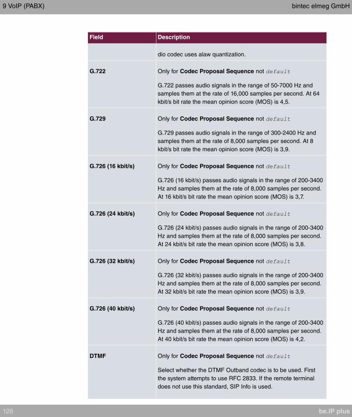
Field Description
dio codec uses alaw quantization.
G.722 Only for Codec Proposal Sequence not
G.722 passes audio signals in the range of 50-7000 Hz and
samples them at the rate of 16,000 samples per second. At 64
kbit/s bit rate the mean opinion score (MOS) is 4,5.
G.729 Only for Codec Proposal Sequence not
G.729 passes audio signals in the range of 300-2400 Hz and
samples them at the rate of 8,000 samples per second. At 8
kbit/s bit rate the mean opinion score (MOS) is 3,9.
G.726 (16 kbit/s) Only for Codec Proposal Sequence not
G.726 (16 kbit/s) passes audio signals in the range of 200-3400
Hz and samples them at the rate of 8,000 samples per second.
At 16 kbit/s bit rate the mean opinion score (MOS) is 3,7.
G.726 (24 kbit/s) Only for Codec Proposal Sequence not
G.726 (24 kbit/s) passes audio signals in the range of 200-3400
Hz and samples them at the rate of 8,000 samples per second.
At 24 kbit/s bit rate the mean opinion score (MOS) is 3,8.
G.726 (32 kbit/s) Only for Codec Proposal Sequence not
G.726 (32 kbit/s) passes audio signals in the range of 200-3400
Hz and samples them at the rate of 8,000 samples per second.
At 32 kbit/s bit rate the mean opinion score (MOS) is 3,9.
G.726 (40 kbit/s) Only for Codec Proposal Sequence not
G.726 (40 kbit/s) passes audio signals in the range of 200-3400
Hz and samples them at the rate of 8,000 samples per second.
At 40 kbit/s bit rate the mean opinion score (MOS) is 4,2.
DTMF Only for Codec Proposal Sequence not
Select whether the DTMF Outband codec is to be used. First
the system attempts to use RFC 2833. If the remote terminal
does not use this standard, SIP Info is used.
9 VoIP (PABX) bintec elmeg GmbH
126 be.IP plus
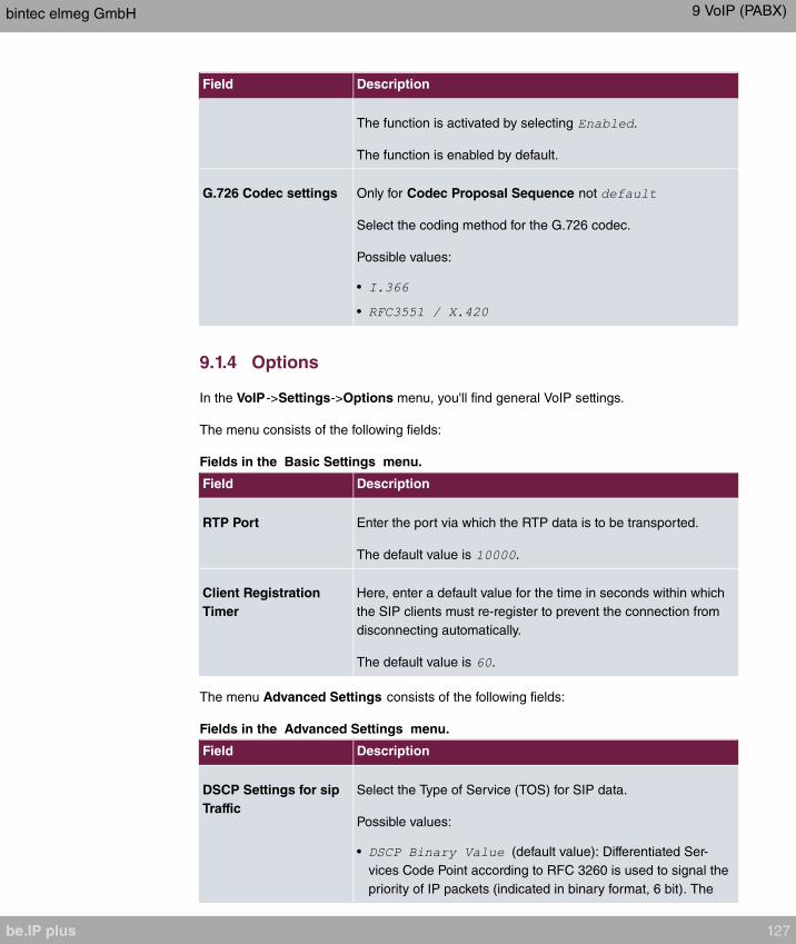
Field Description
The function is activated by selecting .
The function is enabled by default.
G.726 Codec settings Only for Codec Proposal Sequence not
Select the coding method for the G.726 codec.
Possible values:
•
•
9.1.4 Options
In the VoIP->Settings->Options menu, you'll find general VoIP settings.
The menu consists of the following fields:
Fields in the Basic Settings menu.
Field Description
RTP Port Enter the port via which the RTP data is to be transported.
The default value is .
Client Registration
Timer
Here, enter a default value for the time in seconds within which
the SIP clients must re-register to prevent the connection from
disconnecting automatically.
The default value is .
The menu Advanced Settings consists of the following fields:
Fields in the Advanced Settings menu.
Field Description
DSCP Settings for sip
Traffic
Select the Type of Service (TOS) for SIP data.
Possible values:
• (default value): Differentiated Ser-
vices Code Point according to RFC 3260 is used to signal the
priority of IP packets (indicated in binary format, 6 bit). The
bintec elmeg GmbH 9 VoIP (PABX)
be.IP plus 127
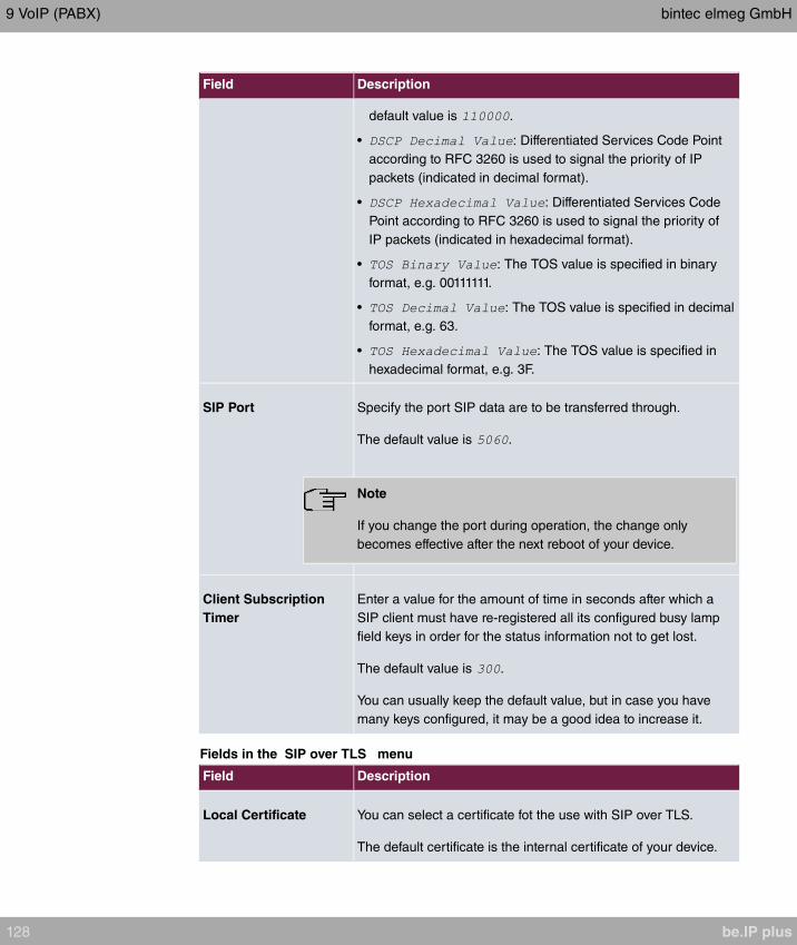
Field Description
default value is .
• : Differentiated Services Code Point
according to RFC 3260 is used to signal the priority of IP
packets (indicated in decimal format).
• : Differentiated Services Code
Point according to RFC 3260 is used to signal the priority of
IP packets (indicated in hexadecimal format).
• : The TOS value is specified in binary
format, e.g. 00111111.
• : The TOS value is specified in decimal
format, e.g. 63.
• : The TOS value is specified in
hexadecimal format, e.g. 3F.
SIP Port Specify the port SIP data are to be transferred through.
The default value is .
Note
If you change the port during operation, the change only
becomes effective after the next reboot of your device.
Client Subscription
Timer
Enter a value for the amount of time in seconds after which a
SIP client must have re-registered all its configured busy lamp
field keys in order for the status information not to get lost.
The default value is .
You can usually keep the default value, but in case you have
many keys configured, it may be a good idea to increase it.
Fields in the SIP over TLS menu
Field Description
Local Certificate You can select a certificate fot the use with SIP over TLS.
The default certificate is the internal certificate of your device.
9 VoIP (PABX) bintec elmeg GmbH
128 be.IP plus
Chapter 10 Numbering
10.1 Trunk Settings
Your system is a telecommunication installation for external connection to the Euro ISDN
(DSS1) and the Internet:
ISDN connections (S0): Depending on module extension, the system features external
ISDN connections (if supported by you device) configured for connection to the network op-
erator's ISDN connection. Depending on module extension, several ISDN connections can
either be set as an internal or external ISDN connection.
10.1.1 Trunks
In the menu Numbering->Trunk Settings ->Trunks you can see the configured external
connections of your system. External connections are configured in the menu VoIP->Set-
tings->SIP Provider or through the respective configuration assistant.
Note
Pure IP devices do not support the creation of new entries.
Values in the Trunks list
Field Description
Nr. Shows the sequential number of the connection.
Description Shows the description of the connection you have configured.
External Port Shows the port this external connections is connected to.
10.1.1.1 Edit or New
Choose the icon to edit existing entries. Choose the New button to create new connec-
tions.
The Numbering->Trunk Settings ->Trunks->New menu consists of the following fields:
Fields in the Basic Settings menu
bintec elmeg GmbH 10 Numbering
be.IP plus 129

Field Description
Description You can enter a designation for the connection you selected.
Access Type Displays the connection type that has been configured.
Possible values:
•
•
•
Port Only for Access Type = or
Select the description for the port via which this external con-
nection is made.
Ports Only for Access Type =
Select the description for the port via which this external con-
nection is made.
All free external ISDN interfaces are available.
Select additional ports with the Add button, e.g. to configure a
party line.
Fields in the Outgoing Signalisation Settings menu
Field Description
Outgoing Signalisation Select the signalling you want for outgoing calls.
Possible values:
• (default value)
•
•
•
Global CLIP no
Screening Number
Only for Outgoing Signalisation =
Here you can enter a number that is to be displayed to the
called party for all external connections.
10 Numbering bintec elmeg GmbH
130 be.IP plus
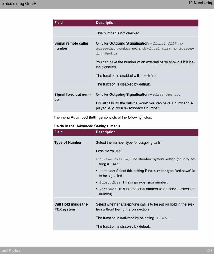
Field Description
This number is not checked.
Signal remote caller
number
Only for Outgoing Signalisation =
and
You can have the number of an external party shown if it is be-
ing signalled.
The function is enabled with .
The function is disabled by default.
Signal fixed out num-
ber
Only for Outgoing Signalisation =
For all calls "to the outside world" you can have a number dis-
played, e. g. your switchboard's number.
The menu Advanced Settings consists of the following fields:
Fields in the Advanced Settings menu
Field Description
Type of Number Select the number type for outgoing calls.
Possible values:
• : The standard system setting (country set-
ting) is used.
• : Select this setting if the number type "unknown" is
to be signalled.
• : This is an extension number.
• : This is a national number (area code + extension
number).
Call Hold inside the
PBX system
Select whether a telephone call is to be put on hold in the sys-
tem without losing the connection.
The function is activated by selecting .
The function is disabled by default.
bintec elmeg GmbH 10 Numbering
be.IP plus 131
10.1.2 Trunk Numbers
In the menu Numbering->Trunk Settings ->Trunk Numbers you assign the external num-
bers and the name indicated in a system telephone display to the external connections
you've defined.
An external connection can be configured as a point-to-multipoint or point-to-point connec-
tion; in the process, the connection description is defined. The intended port name is then
assigned to this connection. The port name (Description) can be defined under Physical
Interfaces->ISDN Ports->ISDN External for the module connection.
External numbers at the point-to-point connection
For a point-to-point connection, you receive a PBX number together with a 1-, 2-, 3- or
4-character extension number range. This extension number range comprises the direct
dial-in numbers for the PBX connection. If you've requested several point-to-point connec-
tions, the number of extensions can be expanded, or you receive another PBX number with
your own extension number range.
With a point-to-point connection, external calls are signalled to the subscriber whose as-
signed internal number corresponds to the dialled extension number. You configure the in-
ternal numbers to be reached directly via direct dial-in of the extension numbers as Intern-
al Number in the menu Numbering->User Settings->User->Add->Trunk Numbers ->In-
ternal Numbers.
Example: You have a point-to-point connection with the PBX number and extension
numbers from to . A call under is normally signalled at the internal sub-
scriber with call number . However, if you enter extension number in this list, you can
define that calls under are signalled at the internal subscriber by call number
.
External subscriber numbers at point-to-multipoint connection
For a point-to-multipoint connection, you can request up to 10 numbers (MSN, multiple
subscriber number) per ISDN connection. These MSNs are the external subscriber num-
bers for your ISDN connections. Definition of the internal number occurs under
Numbering->User Settings->User->Add->Trunk Numbers .
10.1.2.1 Edit or New
Choose the icon to edit existing entries. Choose the New button to create new num-
bers.
The Numbering->Trunk Settings ->Trunk Numbers ->New menu consists of the following
10 Numbering bintec elmeg GmbH
132 be.IP plus
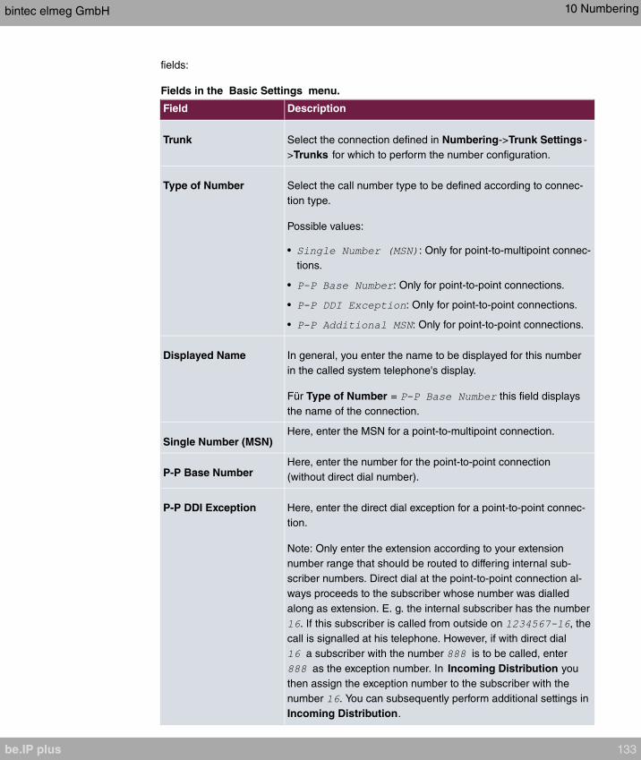
fields:
Fields in the Basic Settings menu.
Field Description
Trunk Select the connection defined in Numbering->Trunk Settings -
>Trunks for which to perform the number configuration.
Type of Number Select the call number type to be defined according to connec-
tion type.
Possible values:
• : Only for point-to-multipoint connec-
tions.
• : Only for point-to-point connections.
• : Only for point-to-point connections.
• : Only for point-to-point connections.
Displayed Name In general, you enter the name to be displayed for this number
in the called system telephone's display.
Für Type of Number = this field displays
the name of the connection.
Single Number (MSN)Here, enter the MSN for a point-to-multipoint connection.
P-P Base NumberHere, enter the number for the point-to-point connection
(without direct dial number).
P-P DDI Exception Here, enter the direct dial exception for a point-to-point connec-
tion.
Note: Only enter the extension according to your extension
number range that should be routed to differing internal sub-
scriber numbers. Direct dial at the point-to-point connection al-
ways proceeds to the subscriber whose number was dialled
along as extension. E. g. the internal subscriber has the number
. If this subscriber is called from outside on , the
call is signalled at his telephone. However, if with direct dial
a subscriber with the number is to be called, enter
as the exception number. In Incoming Distribution you
then assign the exception number to the subscriber with the
number . You can subsequently perform additional settings in
Incoming Distribution.
bintec elmeg GmbH 10 Numbering
be.IP plus 133
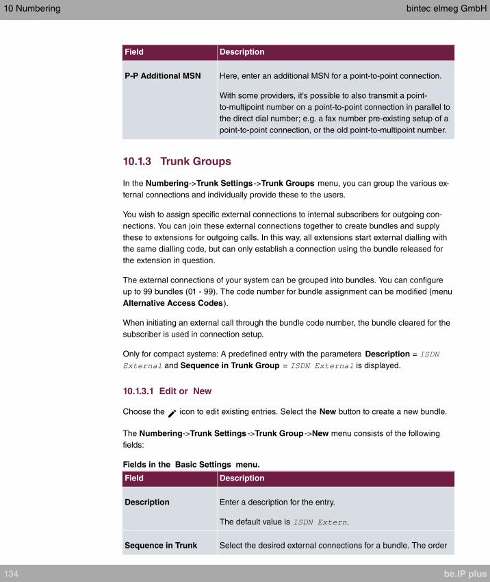
Field Description
P-P Additional MSN Here, enter an additional MSN for a point-to-point connection.
With some providers, it's possible to also transmit a point-
to-multipoint number on a point-to-point connection in parallel to
the direct dial number; e.g. a fax number pre-existing setup of a
point-to-point connection, or the old point-to-multipoint number.
10.1.3 Trunk Groups
In the Numbering->Trunk Settings ->Trunk Groups menu, you can group the various ex-
ternal connections and individually provide these to the users.
You wish to assign specific external connections to internal subscribers for outgoing con-
nections. You can join these external connections together to create bundles and supply
these to extensions for outgoing calls. In this way, all extensions start external dialling with
the same dialling code, but can only establish a connection using the bundle released for
the extension in question.
The external connections of your system can be grouped into bundles. You can configure
up to 99 bundles (01 - 99). The code number for bundle assignment can be modified (menu
Alternative Access Codes).
When initiating an external call through the bundle code number, the bundle cleared for the
subscriber is used in connection setup.
Only for compact systems: A predefined entry with the parameters Description =
and Sequence in Trunk Group = is displayed.
10.1.3.1 Edit or New
Choose the icon to edit existing entries. Select the New button to create a new bundle.
The Numbering->Trunk Settings ->Trunk Group ->New menu consists of the following
fields:
Fields in the Basic Settings menu.
Field Description
Description Enter a description for the entry.
The default value is .
Sequence in Trunk Select the desired external connections for a bundle. The order
10 Numbering bintec elmeg GmbH
134 be.IP plus

Field Description
Group when dialling to the outside matches the sequence of external
connections in this list.
You wish to assign specific external connections for outgoing
connections to the internal subscribers of your system. You can
group external connections into bundles and provide these to
subscribers for the outgoing dialling. In this way, all subscribers
initiate the external dialling with same bundle access code, but
can only set up a connection over the bundles for which they
have been cleared.
10.1.4 X.31
Packet-switched data transmission (X.31)
To improve customer service, you wish to allow cashless payment methods such as debit
or credit card, or record purchase data for a customer card. For this purpose, you connect
a data device to your system, which transmits data for customers and credit cards to a
central location.
You can connect a data device which operates according to the X.31 transmission stand-
ard (data transmission over the D channel) to the system's internal ISDN connections.
These are, for example, checkout terminals, cashpoints or customer card terminals.
For use of these performance features, your network operator provides you TEI's (Terminal
Endpoint Identifier), which you assign to individual connections when configuring your sys-
tem. An additional addressing of these terminals occurs via these TEI's.
Note
You can only use this performance feature if performance feature X.31 has been re-
quested from the network operator, and you operate a corresponding terminal on this
connection. For information on operation, please see the user's guide for your termin-
als.
10.1.4.1 Edit or New
Choose the icon to edit existing entries. Select the New button to set up new X.31 ap-
plications.
The Numbering->Trunk Settings ->X.31->New menu consists of the following fields:
bintec elmeg GmbH 10 Numbering
be.IP plus 135
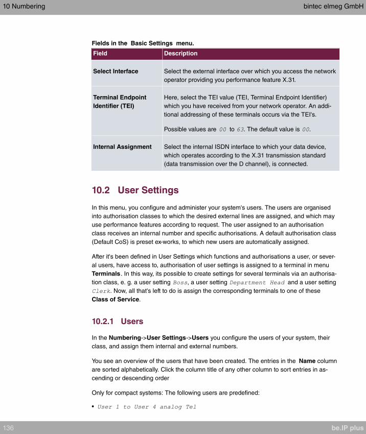
Fields in the Basic Settings menu.
Field Description
Select Interface Select the external interface over which you access the network
operator providing you performance feature X.31.
Terminal Endpoint
Identifier (TEI)
Here, select the TEI value (TEI, Terminal Endpoint Identifier)
which you have received from your network operator. An addi-
tional addressing of these terminals occurs via the TEI's.
Possible values are to . The default value is .
Internal Assignment Select the internal ISDN interface to which your data device,
which operates according to the X.31 transmission standard
(data transmission over the D channel), is connected.
10.2 User Settings
In this menu, you configure and administer your system's users. The users are organised
into authorisation classes to which the desired external lines are assigned, and which may
use performance features according to request. The user assigned to an authorisation
class receives an internal number and specific authorisations. A default authorisation class
(Default CoS) is preset ex-works, to which new users are automatically assigned.
After it's been defined in User Settings which functions and authorisations a user, or sever-
al users, have access to, authorisation of user settings is assigned to a terminal in menu
Terminals. In this way, its possible to create settings for several terminals via an authorisa-
tion class, e. g. a user setting , a user setting and a user setting
. Now, all that's left to do is assign the corresponding terminals to one of these
Class of Service.
10.2.1 Users
In the Numbering->User Settings->Users you configure the users of your system, their
class, and assign them internal and external numbers.
You see an overview of the users that have been created. The entries in the Name column
are sorted alphabetically. Click the column title of any other column to sort entries in as-
cending or descending order
Only for compact systems: The following users are predefined:
•
10 Numbering bintec elmeg GmbH
136 be.IP plus
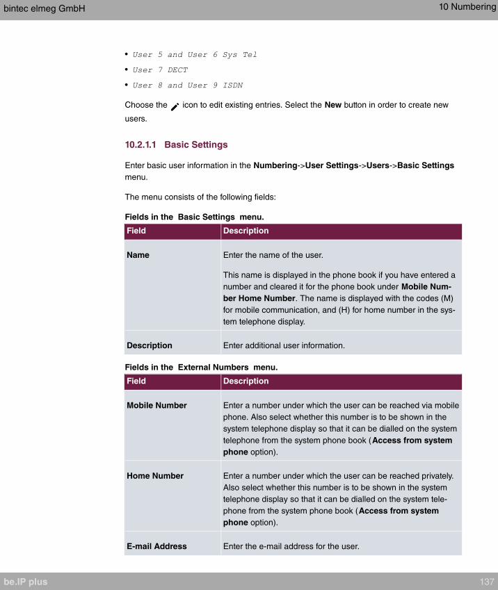
•
•
•
Choose the icon to edit existing entries. Select the New button in order to create new
users.
10.2.1.1 Basic Settings
Enter basic user information in the Numbering->User Settings->Users->Basic Settings
menu.
The menu consists of the following fields:
Fields in the Basic Settings menu.
Field Description
Name Enter the name of the user.
This name is displayed in the phone book if you have entered a
number and cleared it for the phone book under Mobile Num-
ber Home Number. The name is displayed with the codes (M)
for mobile communication, and (H) for home number in the sys-
tem telephone display.
Description Enter additional user information.
Fields in the External Numbers menu.
Field Description
Mobile Number Enter a number under which the user can be reached via mobile
phone. Also select whether this number is to be shown in the
system telephone display so that it can be dialled on the system
telephone from the system phone book (Access from system
phone option).
Home Number Enter a number under which the user can be reached privately.
Also select whether this number is to be shown in the system
telephone display so that it can be dialled on the system tele-
phone from the system phone book (Access from system
phone option).
E-mail Address Enter the e-mail address for the user.
bintec elmeg GmbH 10 Numbering
be.IP plus 137
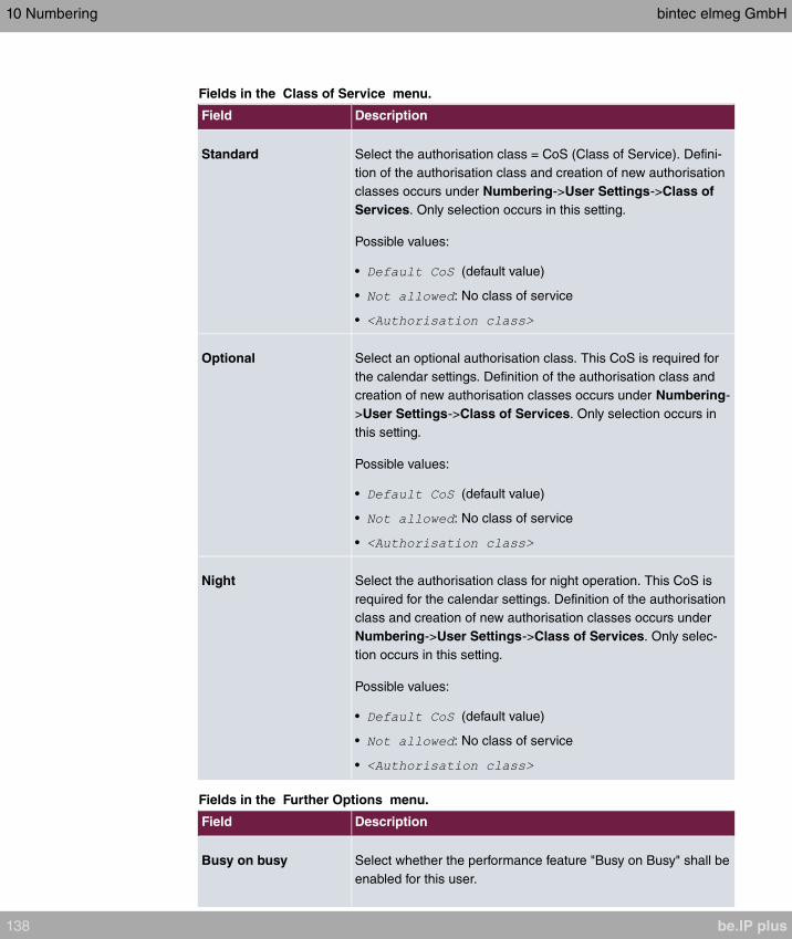
Fields in the Class of Service menu.
Field Description
Standard Select the authorisation class = CoS (Class of Service). Defini-
tion of the authorisation class and creation of new authorisation
classes occurs under Numbering->User Settings->Class of
Services. Only selection occurs in this setting.
Possible values:
• (default value)
• : No class of service
•
Optional Select an optional authorisation class. This CoS is required for
the calendar settings. Definition of the authorisation class and
creation of new authorisation classes occurs under Numbering-
>User Settings->Class of Services. Only selection occurs in
this setting.
Possible values:
• (default value)
• : No class of service
•
Night Select the authorisation class for night operation. This CoS is
required for the calendar settings. Definition of the authorisation
class and creation of new authorisation classes occurs under
Numbering->User Settings->Class of Services. Only selec-
tion occurs in this setting.
Possible values:
• (default value)
• : No class of service
•
Fields in the Further Options menu.
Field Description
Busy on busy Select whether the performance feature "Busy on Busy" shall be
enabled for this user.
10 Numbering bintec elmeg GmbH
138 be.IP plus

Field Description
If a subscriber for whom multiple telephone numbers have been
configured makes a call, you can decide whether additional
calls for this user shall be signalled. If "Busy on Busy" is set for
this user, other callers get an Engaged signal if the user is call-
ing on one of her numbers.
The function is activated by selecting .
The function is disabled by default.
10.2.1.2 Numbers
In the menu Numbering->User Settings->Users->Numbers internal numbers which are
later assigned to the terminals can be entered. Depending on the type, one or more num-
bers can be assigned per terminal.
The menu consists of the following fields:
Fields in the Internal Numbers menu.
Field Description
Internal Numbers Enter the internal numbers for the user and the description to be
shown in the system telephone display (Displayed
Description). In addition, select whether this internal number
shall be displayed in the System Phonebook, and whether the
LED next to the corresponding function key (Busy Lamp Field)
should light up.
The functions are activated by default.
Add new Internal Numbers with Add.
Only for compact systems: Users with the internal numbers ,
, , , , , , and are predefined.
10.2.1.3 Outgoing Signalisation
In the Numbering->User Settings->Users->Outgoing Signalisation menu, select the
outgoing numbers for the user.
For an outgoing call, if the remote subscriber should not see the number assigned to your
own connection, one of the existing numbers can be selected here for display. If no number
is defined, the system transmits no number to the provider.
bintec elmeg GmbH 10 Numbering
be.IP plus 139

Fields in the list Outgoing Signalisation
Field Description
Internal Number Displays the internal numbers configured for the user.
Displayed Description Displays, for each internal number, the description configured
for the system telephone display.
Outgoing Signalisation Select the signal you want for outgoing calls.
Possible values:
• : The user's own exten-
sion is used as the Outgoing Signalisation. This option is
available when there is a point-to-point configuration or a SIP
provider with direct dialling.
• : No Outgoing Signalisation is sent. In this case,
the switchboard uses the port's main number.
• : For a FXO port, the phone num-
ber configured is already assigned as the Outgoing Signal-
isation and is displayed.
• : When more than one number has been
configured, you can select a number that you wish to use as
the Outgoing Signalisation.
Select the icon to specify for each internal number (indicated in the table by Internal
Number and Displayed Description) which number shall be displayed for outgoing calls.
Here, for each configured external connection, select one of the numbers configured for
this purpose.
If more than one external connection has been configured, you can specify the procedure
for outgoing calls. When an external line is engaged, the order of the entries determines
the sequence in which the other lines assigned will be used to dial.
The configured Outgoing Signalisation can be hidden for each outgoing line; to do so, put
a tick under Hide Number in the relevant row.
If you wish to move an entry in the list displayed, select the icon in the relevant row. A
new window opens.
The selected entry is displayed under External Connection, here e. g. .
Proceed as follows to move the selected entry:
(1) Under Move, select in the list the entry relative to which you wish to move the selec-
10 Numbering bintec elmeg GmbH
140 be.IP plus
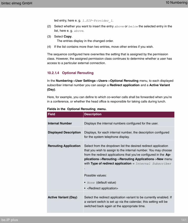
ted entry, here e. g. .
(2) Select whether you want to insert the entry or the selected entry in the
list, here e. g. .
(3) Select Copy.
The entries display in the changed order.
(4) If the list contains more than two entries, move other entries if you wish.
The sequence configured here overwrites the setting that is assigned by the permission
class. However, the assigned permission class continues to determine whether a user has
access to a particular external connection.
10.2.1.4 Optional Rerouting
In the Numbering->User Settings->Users->Optional Rerouting menu, to each displayed
subscriber internal number you can assign a Redirect application and a Active Variant
(Day).
Here, for example, you can define to which co-worker calls shall be forwarded when you're
in a conference, or whether the head office is responsible for taking calls during lunch.
Fields in the Optional Rerouting menu.
Field Description
Internal Number Displays the internal numbers configured for the user.
Displayed Description Displays, for each internal number, the description configured
for the system telephone display.
Rerouting Application Select from the dropdown list the desired redirect application
that you wish to assign to the internal number. You may choose
from the redirect applications that you've configured in the Ap-
plications->Rerouting->Rerouting Applications->New menu
with Type of redirect application =
.
Possible values:
• (default value)
• <Redirect application>
Active Variant (Day) Select the redirect application variant to be currently enabled. If
a variant switch is set up via the calendar, this setting will be
switched back again at the appropriate time.
bintec elmeg GmbH 10 Numbering
be.IP plus 141

Field Description
Possible values:
•
•
•
•
10.2.1.5 Authorizations
In the menu Numbering->User Settings->Users->Authorizations you can allow this user
to make certain settings himself via HTML configuration. For this, a user name and pass-
word must be entered in the user HTML configuration, and personal access authorised.
Once logged out, you can view and modify the corresponding settings after entering this
user name and password.
The menu consists of the following fields:
Fields in the Basic Settings menu.
Field Description
Password for IP Phone
Registration
Enter the password with which a user IP telephone must log into
the system.
The password can remain free if IP telephones log in but need
not authenticate themselves.
PIN for Phone Access Here you can create the PIN for access to protected functions.
These functions are:
• Access to the voice mailbox from a phone not assigned to the
user
• Access to the configuration of the system via the phone via
dial codes
. In the default configuration no PIN is created.
Fields in the User HTML Configuration menu.
Field Description
Personal Access Select whether this user shall receive access authorisation to a
personalised user interface (user access) where he can perform
his own entries and settings.
10 Numbering bintec elmeg GmbH
142 be.IP plus

Field Description
The function is activated by selecting .
The function is disabled by default.
Login Name Only for Personal Access enabled.
Enter a user name for this user. This is required for login on the
user interface.
Password Only for Personal Access enabled.
Enter a password for this user. This is required for login on the
user interface.
Call Through
Call Through consists in dialin to the system via an external connection and the call put
through from the system via another external connection.
Note
In the connection data records, one data record is created for the incoming connection
and one for the outgoing connection.
Fields in the Further Options menu.
Field Description
Call Through Select whether Call Through should be authorised for this user.
The function is activated by selecting .
The function is disabled by default.
When you enable the function, you must select under Use rout-
ing and signalisation from number the internal number from
which the authorised external lines and call options for Call
Through shall be used.
bintec elmeg GmbH 10 Numbering
be.IP plus 143
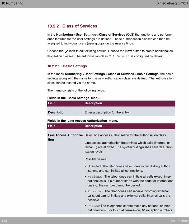
10.2.2 Class of Services
In the Numbering->User Settings->Class of Services (CoS) the functions and perform-
ance features for the user settings are defined. These authorisation classes can then be
assigned to individual users (user groups) in the user settings.
Choose the icon to edit existing entries. Choose the New button to create additional au-
thorisation classes. The authorisation class is configured by default.
10.2.2.1 Basic Settings
In the menu Numbering->User Settings->Class of Services->Basic Settings, the basic
settings along with the name for the new authorisation class are defined. The authorisation
class can be located via the name.
The menu consists of the following fields:
Fields in the Basic Settings menu.
Field Description
Description Enter a description for the entry.
Fields in the Line Access Authorization menu.
Field Description
Line Access Authoriza-
tion
Select line access authorisation for the authorisation class.
Line access authorisation determines which calls (internal, ex-
ternal,...) are allowed. The system distinguishes several author-
isation levels.
Possible values:
• Unlimited: The telephones have unrestricted dialling author-
isations and can initiate all connections.
• : The telephones can initiate all calls except inter-
national calls. If a number starts with the code for international
dialling, the number cannot be dialled.
• : The telephones can receive incoming external
calls, but cannot initiate any external calls. Internal calls are
possible.
• : The telephones cannot make any national or inter-
national calls. For this dial permission, 10 exception numbers
10 Numbering bintec elmeg GmbH
144 be.IP plus

Field Description
allowing national or international dialling can be configured.
An exception number can consist of complete call numbers or
sections thereof (e. g. the first numerals).
• : The telephones can make local calls. National and in-
ternational calls are not possible.
• : The telephones do not have authorisation for in-
coming or outgoing external calls. Only internal telephone
calls are possible.
Automatic Outside
Line
This setting defines whether automatic outside line is set up for
this authorisation class. With automatic outside line, users of
this authorisation class hear the external dialling tone after pick-
ing up the receiver and can immediately dial outside. To make
internal calls, press the star key after picking up the receiver.
Note
If you are conducting an external call when automatic out-
side line access is active and then want to start a second
external call, you must select a leading for the second
call so that it can be set up.
If you have set up an automatic outside line for an internal sub-
scriber, the keypad functions cannot be directly used. First dis-
able the Automatic Outside Line or dial the star key, then the
code for manual outside line (e. g. 0) followed by keypad dial-
ling, beginning with the star or hash key.
Trunk Line Selection
with Line Access Num-
ber
Select the connections over which outgoing calls from these
telephones shall be externally routed. The order of entries de-
termines in which sequence, in case of an engaged external
line, dialling shall occur over the other assigned lines
Allow manual trunk
group selection
Besides general exchange access, a telephone can also select-
ively use a bundle. Here an external connection is initiated with
the corresponding code for the target assignment of the bundle
and not by dialling the dialling code.
To be able to perform a selective bundle assignment, the au-
thorisation class must possess the appropriate authorisation.
The authorisation can also include bundles that the authorisa-
tion class can otherwise not assign. If a telephone does not pos-
bintec elmeg GmbH 10 Numbering
be.IP plus 145

Field Description
sess the authorisation for selective bundle assignment, or if the
selected bundle is in use, the busy tone is heard after dialling
the code. If Automatic outside line is set up for an authorisa-
tion class, users of this authorisation class must press the star
key before selective bundle assignment, then initiate external di-
alling with the code for bundle assignment.
The function is activated by selecting .
The function is disabled by default.
Then select the bundles for which manual bundle assignment is
to be allowed. You can configure bundles in the
Numbering->Trunk Settings ->Trunk Groups menu.
Number display
If you call a subscriber, your number is displayed to him. The person you're calling thus
sees that you are calling even before picking up the receiver. If you don't want the person
you're calling to see your number before picking up the receiver, you can prevent display of
your number to your called party.
If your called party has set up call forwarding, you won't know at which telephone you've
reached him. In this case, you can display the number to which your called party has for-
warded the call. However, the person you're calling also has the option of preventing dis-
play of this number.
Call number display allows display of the caller's number already at call signaling, even on
analogue telephones. Thus, you know who wishes to speak to you even before you've ac-
cepted the call.
Note
Transmission of analogue CLIP data can be set up separately for every analogue con-
nection. Please refer to the users' guides for your analogue terminals to determine
whether these support the "CLIP" and "CLIP off Hook" performance features.
Not all described performance features are included in the ISDN standard connection.
Please inquire of your network operator the extent to which individual performance fea-
tures must be separately ordered for your ISDN connection.
The menu Advanced Settings consists of the following fields:
10 Numbering bintec elmeg GmbH
146 be.IP plus

Fields in the Further Settings menu.
Field Description
Dial Control Select whether numbers entered in the Call Routing->Outgo-
ing Services->Dial Control menu shall be allowed or denied
also for this authorisation class.
The function is activated by selecting .
The function is disabled by default.
Automatic Route Se-
lection (ARS)
Select whether the routing rules entered in the Call
Routing->Automatic Route Selection menu shall also be ap-
plied to this authorisation class.
The function is activated by selecting .
The function is disabled by default.
Show Outgoing Num-
ber (CLIP)
Select whether the caller number shall be displayed to the
called party.
The function is activated by selecting .
The function is enabled by default.
Show Connected Num-
ber (COLP)
Select whether the called party number shall be displayed to the
caller.
If, for example, the called party has set up call forwarding to a
third subscriber, the caller can display the number of the call for-
warding destination using this performance feature.
The function is activated by selecting .
The function is enabled by default.
Additional Info for Ex-
tern Call
Select what should be displayed for an exchange call.
Possible values:
• : The display shows the ex-
change connection and the assigned name alternatively.
• : Only the name assigned to the ex-
change connection is displayed.
• (default value): The display shows the
bintec elmeg GmbH 10 Numbering
be.IP plus 147
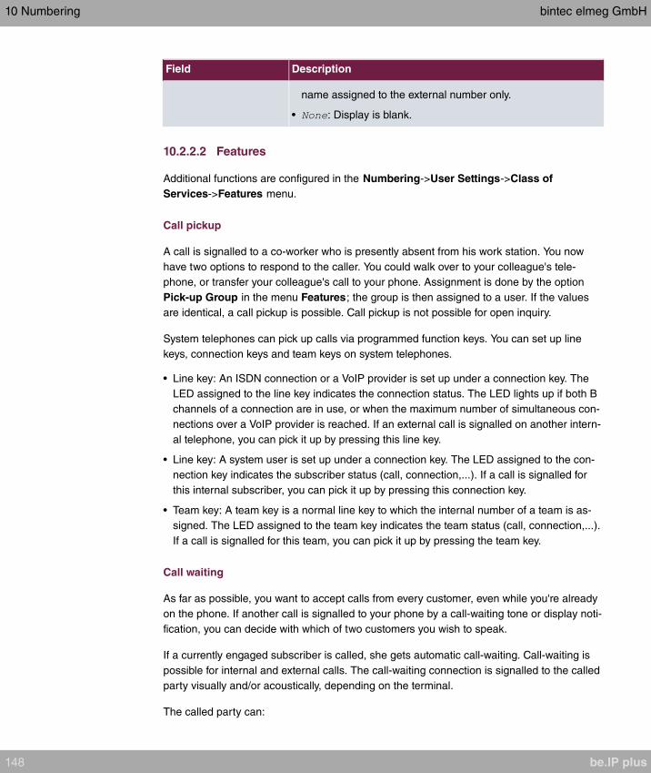
Field Description
name assigned to the external number only.
• : Display is blank.
10.2.2.2 Features
Additional functions are configured in the Numbering->User Settings->Class of
Services->Features menu.
Call pickup
A call is signalled to a co-worker who is presently absent from his work station. You now
have two options to respond to the caller. You could walk over to your colleague's tele-
phone, or transfer your colleague's call to your phone. Assignment is done by the option
Pick-up Group in the menu Features; the group is then assigned to a user. If the values
are identical, a call pickup is possible. Call pickup is not possible for open inquiry.
System telephones can pick up calls via programmed function keys. You can set up line
keys, connection keys and team keys on system telephones.
• Line key: An ISDN connection or a VoIP provider is set up under a connection key. The
LED assigned to the line key indicates the connection status. The LED lights up if both B
channels of a connection are in use, or when the maximum number of simultaneous con-
nections over a VoIP provider is reached. If an external call is signalled on another intern-
al telephone, you can pick it up by pressing this line key.
• Line key: A system user is set up under a connection key. The LED assigned to the con-
nection key indicates the subscriber status (call, connection,...). If a call is signalled for
this internal subscriber, you can pick it up by pressing this connection key.
• Team key: A team key is a normal line key to which the internal number of a team is as-
signed. The LED assigned to the team key indicates the team status (call, connection,...).
If a call is signalled for this team, you can pick it up by pressing the team key.
Call waiting
As far as possible, you want to accept calls from every customer, even while you're already
on the phone. If another call is signalled to your phone by a call-waiting tone or display noti-
fication, you can decide with which of two customers you wish to speak.
If a currently engaged subscriber is called, she gets automatic call-waiting. Call-waiting is
possible for internal and external calls. The call-waiting connection is signalled to the called
party visually and/or acoustically, depending on the terminal.
The called party can:
10 Numbering bintec elmeg GmbH
148 be.IP plus

• Decline the call-waiting connection and proceed with the current call. The caller is then
signalled "engaged".
• Accept the call-waiting connection and hold the current connection.
• Accept the call-waiting connection after the current connection is ended.
• Ignore the call-waiting connection. Call-waiting automatically ends after 30 seconds and
the caller hears a "busy" signal.
Analogue terminals
The call-waiting option can be individually configured for every subscriber. Allowing call
waiting or not can be set via configuration or via a code number in operations.
Analogue terminals get the system call waiting tone. The number of the call-waiting party
can be shown in the analogue telephone display if it features the corresponding perform-
ance feature (CLIP off Hook). CLIP off Hook is disabled for analogue terminals in the basic
setting, but may be enabled via configuration.
Call waiting can only occur simultaneously in the system for a limited number of analogue
connections. If call waiting is already operating with this maximum number of call-waiting
tones on analogue connections, additional call-waiting callers will get the busy tone.
If you hear the call-waiting tone during a call, you can take that call and transfer the ongo-
ing call An operating procedure allows transfer of the ongoing call and acceptance of the
call waiting. The following conditions apply here:
• Every dialled number is accepted by the system.
• After the operation procedure, the subscriber and the call-waiting subscriber are immedi-
ately connected to each other (no acknowledge tones).
• Transfer to one's own number is possible, then call waiting.
• Internal, external target subscribers as well as teams can be dialled.
• A return call occurs in case of invalid or engaged target number.
• If the subscriber is free, a return call is made according to the target subscriber's defined
period.
• With transfer to a team number, there is no return call in case of an engaged or unreach-
able team
• With transfer to a team number only return call after time is supported.
ISDN terminals
Configuration and operation of call waiting occurs as described in the users' guides of the
corresponding terminals. ISDN terminals use their own tones to signal call waiting.
bintec elmeg GmbH 10 Numbering
be.IP plus 149

Note
Call waiting is not possible:
• for conference calls
• for do not disturb (analogue terminals)
• for announcements
• for room monitoring
• for terminals, for which the Data Protection performance feature is set up (e. g. fax,
modem)
• in analogue subscriber's dialling status (the receiver has been picked up, but there is
no connection yet)
• for current call-waiting protection
• for dialling a team number. Then there is no call waiting for analogue team sub-
scribers.
ISDN telephones can also transfer a call waiting to another subscriber via the "Call De-
flection" performance feature. An active connection is ended by replacing the receiver,
for example. The call waiting connection is then signalled and can be accepted, e. g.
by picking up the receiver.
The Numbering->User Settings->Class of Services->Features menu consists of the fol-
lowing fields:
Fields in the Feature Authorization menu.
Field Description
Pick-up Group Enter the number of the group in which calls may be picked up.
Call Waiting Select whether call waiting shall be allowed for this authorisa-
tion class.
The function is activated by selecting .
The function is enabled by default.
Use global rerouting Select whether global redirect shall be allowed for this author-
isation class.
The function is activated by selecting .
The function is disabled by default.
10 Numbering bintec elmeg GmbH
150 be.IP plus

Field Description
Note
The redirect target must be in a class of service that does
not allow global redirect.
Switch signalling vari-
ants manually
Select whether manual switching of call options shall be allowed
for this authorisation class.
The function is activated by selecting .
The function is disabled by default.
Call Through Select whether Call Through shall be allowed for this authorisa-
tion class.
The function is activated by selecting .
The function is enabled by default.
Simplex operation
The simplex operation function allows you to set up a connection from a system telephone
to another system telephone without this connection having to be actively accepted by the
called system telephone (pick up receiver, switch on loudspeaker/hands-free). As soon as
the system telephone has accepted the simplex operation connection, the connection is set
up. The caller and the called system telephone hear an attention tone at the beginning of
the simplex operation. Duration of the simplex operation is limited to two minutes. If the re-
ceiver of a concerned telephone is picked up during this period, the call is translated into a
normal connection.
System telephones can initiate a simplex operation call via the system telephone menu or a
programmed function key. If the simplex operation is initiated via a function key, notifica-
tions appear in the system telephone display as with a normal connection and the simplex
operation key LED is switched on. The simplex operation can be ended by renewed press-
ing of the function key or by pressing the loudspeaker key. The LED switches off again at
conclusion of the simplex operation.
If a telephone or a system telephone is the destination of a simplex operation call, the
caller's number is indicated in the display. The simplex operation call is signalled over the
loudspeaker with an attention tone. Simplex operation can be terminated with the ESC key.
A function key can also be configured on a system telephone to deny or allow simplex op-
eration calls.
bintec elmeg GmbH 10 Numbering
be.IP plus 151

Note
Simplex operation calls are automatically accepted by the called telephone by enabling
the hands-free function, if:
• the telephone is not in use
• simplex operation is allowed and
• the "Do not disturb" function (Call Protection) is disabled.
If a simplex operation connection is not ended by both subscribers, the connection is
automatically ended by the system after ca. 2 minutes.
Message
Do you wish to call your co-workers to a meeting or to a meal? You could call each of them
individually, or simply use the announcement function. With just one call, you reach all the
announcement-enabled telephones without subscribers having to pick up the receiver.
Caution
Although you can be heard with the announcement, you cannot hear any comments
your colleagues or family members make.
The announcement function allows you to set up a connection to another telephone without
this connection having to be actively accepted by the latter (pick up receiver or switch on
loudspeaker/hands-free). As soon as a telephone has accepted the announcement, the
connection is active. The announcer and the called subscriber initially hear a positive ac-
knowledge tone. Announcement duration is unlimited.
Announcements are possible to ISDN and analogue telephones if these support the an-
nouncement performance feature. Please refer to the user's guide for your telephones to
determine whether the performance feature is supported.
Announcements can be allowed or denied to telephones via a code number.
System telephones
Announcement to and from system telephones is possible. System telephones can initiate
an announcement via the system telephone menu or using a programmed function key. If
the announcement is initiated via a function key, notifications appear in your telephone dis-
play as with a normal connection and the announcement key LED is switched on. The an-
nouncement can be ended by renewed pressing of the function key or by pressing the
10 Numbering bintec elmeg GmbH
152 be.IP plus

loudspeaker key. The LED switches off again at conclusion of the announcement.
If a system telephone is the destination for an announcement, the number of the announcer
appears on the display. The announcement is signalled with a positive acknowledge tone
over the loudspeaker. The announcement can be terminated with the ESC key.
A function key with associated LED can also be set up on a system telephone to deny or
allow announcements.
Individual announcement
You can initiate the announcement in a selective manner by dialling an internal number.
The announcement can be allowed or denied by the destination subscriber via an operating
procedure. The announcement is signalled to the destination subscriber and the announcer
with a positive acknowledge tone.
Team announcement
An announcement can also be made to a team by dialling a team number. The team sub-
scribers hear the announcement simultaneously. The announcement is signalled to the
destination subscribers and the announcers with a positive acknowledge tone. The an-
nouncement to a team is also possible from an inquiry. With a team announcement, it can
take up to four seconds before the connection to the individual team subscribers is estab-
lished. The announcement then proceeds to the team subscribers who have accepted the
announcement within this period.
Note
Announcements are automatically accepted by the called telephone by enabling the
loudspeaker function, if:
• the telephone is not in use
• the announcement is set up and
• the "Do not disturb" function is not active.
MWI (Message Waiting Indication)
You've got new messages in your mailbox, or new e-mails waiting at your Internet service
provider. as you have no prior knowledge, you must constantly check whether you do actu-
ally have new messages. With the MWI performance feature, your system receives the in-
formation about new messages from the corresponding service provider. Now you merely
need query your mailbox or e-mail POB if new messages really are present. You can also
send a MWI from a voicebox connected to the system, or from a system telephone set up
bintec elmeg GmbH 10 Numbering
be.IP plus 153

as a reception telephone.
This information can be displayed or signalled on terminals (analogue terminals, ISDN ter-
minals and system telephones) that support this performance feature. MMW information
from outside is conveyed transparently by the system. When an MMI is present, the bintec
elmeg telephone displays an envelope symbol and a text generated in the telephone, along
with the caller's phone number.
Analogue terminals
• Switching on the MMI can only occur with receiver replaced.
• If there's a message from a voicemail system, there's a short call. Depending on the ter-
minal, a symbol, a text generated in the telephone as well as the caller's telephone num-
ber can be displayed. If MWI information is deleted, there is no signalling.
• For the terminal, CLIP must be set up and enabled in the configuration.
• Callback to the voice mail system or reception telephone is possible; the MMI information
is deleted in the process.
ISDN terminals
• Switching on the MWI is possible at all times (also during the call).
• If there's a message from a voicemail system, there's a short call. Depending on the ter-
minal, a symbol, a text generated in the telephone as well as the caller's telephone num-
ber can be displayed. If MWI information is deleted, there is no signalling.
• Callback to the voice mail system or reception telephone is possible; the MMI information
is deleted in the process.
System telephones
• Switching on the MWI is possible at all times (also during the call). The caller's number is
entered in the caller list. Depending on the type of system telephone, e. g. external voice-
mail, Netbox Heute, the name and number of the caller are entered. In addition, the
Caller list LED flashes.
• Callback to the voice mail system or reception telephone is possible; the MMI information
is deleted in the process.
Hotel room telephone
• If a message from a voicemail system is present, a special dialling tone is heard after the
receiver is picked up.
Reception telephone
• MWI information can be switched on and off from a reception telephone to a room tele-
10 Numbering bintec elmeg GmbH
154 be.IP plus

phone via a telephone procedure. If MWI information is switched to a room telephone,
the reception telephone number is entered into the caller list and the special dialling tone
is enabled.
Disabling the MWI announcement
• Manual disabling via reception telephone procedure.
• Call from reception telephone to room telephone. The MWI information is automatically
deleted in call status.
• Callback from room telephone to reception telephone deletes the MWI information.
Note
This performance feature must be requested for your ISDN connection from the net-
work operator. There, you will also be informed of available services. The information
can only be displayed on the internal ISDN terminal if an external MSN has been as-
signed to the terminal in the configuration.
All MWI data are deleted after a system reset.
Net Direct (keypad)
Some time ago, you purchased the most advanced telephone of the time. Since then,
however, a number of new performance features have appeared on the public network,
which cannot be used by simply pressing a key. You can use the keypad function to em-
ploy your network operator's current ISDN functions by entering a key sequence from your
ISDN or analogue telephone.
The keypad function allows control of service or performance features in your operator's
network by entering character and numerical sequences.
Note
You can only use the keypad performance feature if it is supported by your network
operator and has been requested for your ISDN connection. If you have set up an
automatic outside line for an internal subscriber, the keypad functions cannot be dir-
ectly used. First disable the Automatic Outside Line or dial the star key, then the
code for manual outside line (e. g. 0) followed by keypad dialling, beginning with the
star or hash key.
Keypad functions can only operate from terminals that have been assigned an external
multiple subscriber number (MSN) in configuration and possess a keypad authorisa-
tion.
bintec elmeg GmbH 10 Numbering
be.IP plus 155

Your network operator's performance features are always set up for the number (MSN)
sent by your terminal.
The menu Advanced Settings consists of the following fields:
Fields in the Advanced Settings menu.
Field Description
Receive System Inter-
com Call
Select whether simplex operation calls to the system telephone
shall be allowed for this authorisation class.
The function is activated by selecting .
The function is enabled by default.
Receive Announce-
ment Calls
Select whether this authorisation class may receive announce-
ments.
The function is activated by selecting .
The function is enabled by default.
Receive MWI Informa-
tion
Select whether this authorisation class may receive information
about existing messages (MWI = Message Waiting Indication).
The function is activated by selecting .
The function is enabled by default.
Net Direct (Keypad) Select whether you wish to use your network operator's current
ISDN functions also from older ISDN or analogue telephones by
entering a key sequence.
The function is activated by selecting .
The function is disabled by default.
10.2.2.3 Applications
Additional applications are configured in the Numbering->User Settings->Class of Ser-
vices->Applications menu.
The menu consists of the following fields:
Fields in the Application Authorization menu.
10 Numbering bintec elmeg GmbH
156 be.IP plus

Field Description
System Phonebook
Authorization
Select whether this authorisation class may use entries in the
system phone book and, if so, to what extent.
Possible values:
•
(default value): System phone book entries
may be used unless located beyond the configured line ac-
cess authorisation.
• : System phone book
entries may be used in unrestricted access.
• : System phone book entries may not be used.
Music on Hold Select whether and which MoH (Music on Hold) shall be used.
Possible values:
• (default value): A caller on hold shall hear no music-
on-hold.
• : A caller on hold should hear the selec-
ted Wave file as music-on-hold.
• (default value for compact systems)
•
•
Doorcom Access Select whether this authorisation class may connect to the door
intercom.
The function is activated by selecting .
The function is enabled by default.
TAPI Select whether this authorisation class may use the system's
TAPI functionalities.
The function is activated by selecting .
The function is enabled by default.
Save call data records Define whether the connection data of this authorisation class
shall be saved.
The function is activated by selecting .
bintec elmeg GmbH 10 Numbering
be.IP plus 157
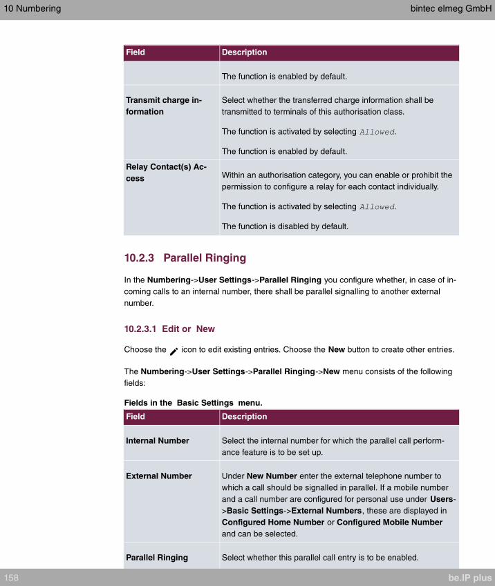
Field Description
The function is enabled by default.
Transmit charge in-
formation
Select whether the transferred charge information shall be
transmitted to terminals of this authorisation class.
The function is activated by selecting .
The function is enabled by default.
Relay Contact(s) Ac-
cess Within an authorisation category, you can enable or prohibit the
permission to configure a relay for each contact individually.
The function is activated by selecting .
The function is disabled by default.
10.2.3 Parallel Ringing
In the Numbering->User Settings->Parallel Ringing you configure whether, in case of in-
coming calls to an internal number, there shall be parallel signalling to another external
number.
10.2.3.1 Edit or New
Choose the icon to edit existing entries. Choose the New button to create other entries.
The Numbering->User Settings->Parallel Ringing->New menu consists of the following
fields:
Fields in the Basic Settings menu.
Field Description
Internal Number Select the internal number for which the parallel call perform-
ance feature is to be set up.
External Number Under New Number enter the external telephone number to
which a call should be signalled in parallel. If a mobile number
and a call number are configured for personal use under Users-
>Basic Settings->External Numbers, these are displayed in
Configured Home Number or Configured Mobile Number
and can be selected.
Parallel Ringing Select whether this parallel call entry is to be enabled.
10 Numbering bintec elmeg GmbH
158 be.IP plus
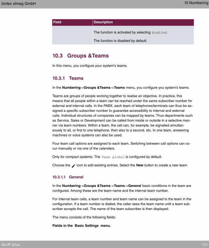
Field Description
The function is activated by selecting .
The function is disabled by default.
10.3 Groups &Teams
In this menu, you configure your system's teams.
10.3.1 Teams
In the Numbering->Groups &Teams->Teams menu, you configure you system's teams.
Teams are groups of people working together to realise an objective. In practice, this
means that all people within a team can be reached under the same subscriber number for
external and internal calls. In the PABX, each team of telephones/terminals can thus be as-
signed a specific subscriber number to guarantee accessibility to internal and external
calls. Individual structures of companies can be mapped by teams. Thus departments such
as Service, Sales or Development can be called from inside or outside in a selective man-
ner via team numbers. Within a team, the call can, for example, be signalled simultan-
eously to all, or first to one telephone, then also to a second, etc. In one team, answering
machines or voice systems can also be used.
Four team call options are assigned to each team. Switching between call options can oc-
cur manually or via one of the calendars.
Only for compact systems: The is configured by default.
Choose the icon to edit existing entries. Select the New button to create a new team.
10.3.1.1 General
In the Numbering->Groups &Teams->Teams->General basic conditions in the team are
configured. Among these are the team name and the internal team number.
For internal team calls, a team number and team name can be assigned to the team in the
configuration. If a team number is dialled, the caller sees the team name until a team sub-
scriber accepts the call. The name of the team subscriber is then displayed.
The menu consists of the following fields:
Fields in the Basic Settings menu.
bintec elmeg GmbH 10 Numbering
be.IP plus 159

Field Description
Description Enter a description for the team.
Internal Number Enter the internal number of the team.
Fields in the Further Settings menu.
Field Description
Switch call signalling Define whether the call option configured for the team shall be
enabled manually over the telephone, or via the calendar. For
this, calendar and switching times must first have been con-
figured. You can create up to four call variants for each team in
the menu Numbering->Groups
&Teams->Teams->New->Variant1-4 .
Possible values:
• (default value): Manual
switch is enabled.
• : Select one of the configured calendars.
Active Variant (Day) Select one of the call options to be currently enabled. If a switch
is set up via the calendar, this setting will be switched back
again in a timely manner.
The default value is .
Permit Call Forwarding Define whether call forwarding may occur for the team.
The function is activated by selecting .
The function is disabled by default.
Call Forwarding to Ex-
ternal Numbers
Define whether there shall be call forwarding within the system
itself (Through PABX , default value) or via an exchange
(provider, Through Exchange Office ). Please note that for call
forwarding within the system two external connections are used.
The menu Advanced Settings consists of the following fields:
Fields in the Timer menu.
Field Description
Team Speed Timer Here, enter the Team Speed Timer following which call for-
10 Numbering bintec elmeg GmbH
160 be.IP plus

Field Description
warding after time shall be performed in the team. The default
value is seconds.
Simultaneous after
time
With linear and rotating team calls, there is the option for all
team subscribers to be simultaneously called after a defined
period.
The default value is seconds.
Wrap-up Timer This setting is only enabled in Signalling
.
For every subscriber who has ended a call, a Post processing
time is configured, during which he receives no more calls.
Calls received by the subscriber on his number rather than via
the team and self-initiated calls are not included in the time cal-
culation.
The default value is seconds; the range … seconds.
10.3.1.2 Variant 1 - 4
In the Numbering->Groups &Teams->Teams->Variant 1 - 4 you configure a team's four
call variants. You can create up to four different call options for each team. For this, assign
either an internal or external number to the call option, and define how an incoming call
should be signalled within the team.
Internal numbers of a team
Under Internal Assignment, select the internal subscribers who are to belong to this team.
If you wish to temporarily exclude a team subscribers from call signalling (e. g. team sub-
scriber is on holiday), you can Logout the subscriber. Team calls are not signalled to
logged out subscribers. Every team subscriber can also control login and logout himself via
a system code.
For internal team calls, a team number and team name can be assigned to the team in the
configuration. If a team number is dialled, the caller sees the team name until a team sub-
scriber accepts the call. The name of the team subscriber is then displayed. A call to a
team can be simultaneous, linear, rotating, setting up or parallel after time. With linear and
rotating team calls, there is the option for all team subscribers to be simultaneously called
after a defined period (1 - 99).
The Numbering->Groups &Teams->Teams->Variant menu consists of the following
fields:
bintec elmeg GmbH 10 Numbering
be.IP plus 161

Fields in the Basic Settings menu.
Field Description
Assignment You can assign several internal numbers to each team, or an
external number to each. Define whether calls for a team shall
be signalled to internal or external subscribers.
Possible values:
• : The entered external number is called.
• (default value): The subscribers assigned to the
selected number are called according to the defined sig-
nalling.
Internal Assignment Only if Assignment =
Select the internal team subscribers.
With Add, you add more internal numbers.
Only for compact systems: The numbers , , , are as-
signed to the .
External Assignment Only if Assignment =
Enter the number of the external subscriber.
Route and Charge As-
signment
Only if Assignment =
Charges for the call and assignment of an external connection
occur via the selected internal subscriber.
Automatic call acceptance in the team
You want a caller to be accepted already at call signalling and not to hear the ringing tone.
That's no problem if you're using automatic call acceptance for team calls. In this case, the
caller is automatically accepted by the system and hears an announcement or system mu-
sic-on-hold. During this time, the call is signalled to the entered team subscribers. If a sub-
scriber takes the call, the connection to the caller is established.
If a team is called, it can be defined in configuration that the call is automatically accepted,
and that the caller hears an announcement or music. The target subscriber(s) are called
during this time. After the receiver is picked up, the announcement or music is turned off
and the subscribers are connected to each other.
Possible settings for automatic call acceptance:
10 Numbering bintec elmeg GmbH
162 be.IP plus
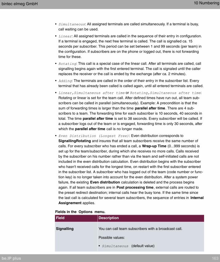
• : All assigned terminals are called simultaneously. If a terminal is busy,
call waiting can be used.
• : All assigned terminals are called in the sequence of their entry in configuration.
If a terminal is engaged, the next free terminal is called. The call is signalled ca. 15
seconds per subscriber. This period can be set between 1 and 99 seconds (per team) in
the configuration. If subscribers are on the phone or logged out, there is not forwarding
time for these.
• : This call is a special case of the linear call. After all terminals are called, call
signalling begins again with the first entered terminal. The call is signaled until the caller
replaces the receiver or the call is ended by the exchange (after ca. 2 minutes).
• : The terminals are called in the order of their entry in the subscriber list. Every
terminal that has already been called is called again, until all entered terminals are called.
• or :
Rotating or linear is set for the team call. After defined times have run out, all team sub-
scribers can be called in parallel (simultaneously). Example: A precondition is that the
sum of forwarding times is larger than the time parallel after time. There are 4 sub-
scribers to a team. The forwarding time for each subscriber is 10 seconds, 40 seconds in
total. The time parallel after time is set to 38 seconds. Every subscriber will be called. If
a subscriber logs out of the team or is engaged, forwarding time is only 30 seconds, after
which the parallel after time call is no longer made.
• : Even distribution corresponds to
SignallingRotating and insures that all team subscribers receive the same number of
calls. For every subscriber who has ended a call, a Wrap-up Time (0...999 seconds) is
set up for the team/subscriber, during which she receives no more calls. Calls received
by the subscriber on his number rather than via the team and self-initiated calls are not
included in the even distribution calculation. Even distribution begins with the subscriber
who hasn't received calls for the longest time, on restart with the first subscriber entered
in the subscriber list. A subscriber who has logged out of the team (code number or func-
tion key) is no longer taken into account for the even distribution. After a system power
failure, the existing Even distribution calculation is deleted and the process begins
again. If all team subscribers are in Post processing time, external calls are routed to
the preset redirect destination; internal calls hear the busy tone. If the same time since
the last call is calculated for several team subscribers, the sequence of entries in Internal
Assignement applies.
Fields in the Options menu.
Field Description
Signalling You can call team subscribers with a broadcast call.
Possible values:
• (default value)
bintec elmeg GmbH 10 Numbering
be.IP plus 163
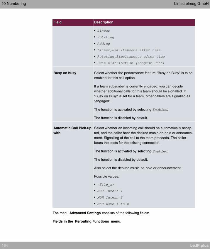
Field Description
•
•
•
•
•
•
Busy on busy Select whether the performance feature "Busy on Busy" is to be
enabled for this call option.
If a team subscriber is currently engaged, you can decide
whether additional calls for this team should be signalled. If
"Busy on Busy" is set for a team, other callers are signalled as
"engaged".
The function is activated by selecting .
The function is disabled by default.
Automatic Call Pick-up
with
Select whether an incoming call should be automatically accep-
ted, and the caller hear the desired music-on-hold or announce-
ment. Signalling of the call to the team proceeds. The caller
bears the costs for the existing connection.
The function is activated by selecting .
The function is disabled by default.
Also select the desired music-on-hold or announcement.
Possible values:
•
•
•
•
The menu Advanced Settings consists of the following fields:
Fields in the Rerouting Functions menu.
10 Numbering bintec elmeg GmbH
164 be.IP plus

Field Description
Rerouting on no re-
sponse
Select whether and, if so, to which team an incoming call should
be redirected on no reply.
Possible values:
• (default value)
•
Also enter the time after which the call should be redirected.
Further Rerouting Select whether and, if so, to which redirect option an incoming
call shall be switched.
Possible values:
• (default value): No other redirect options are used.
• : The incoming call is immediately rerouted to
the redirect function selected in Immediately.
• : The incoming call is rerouted to the redirect func-
tion selected in On Busy.
Immediately Only if Further Rerouting =
Select the redirect function for immediate redirect. Configure re-
direct functions in Applications->Rerouting->Rerouting Func-
tions.
On Busy Only if Further Rerouting =
Select the redirect function for redirect on engaged. Configure
redirect functions in Applications->Rerouting->Rerouting
Functions.
Busy starting with Only if Further Rerouting =
Select from which number of subscribers the team is considered
engaged.
10.3.1.3 Log on / Log off
In the Numbering->Groups &Teams->Teams->Log on / Log off individual team mem-
bers are logged in or out.
bintec elmeg GmbH 10 Numbering
be.IP plus 165
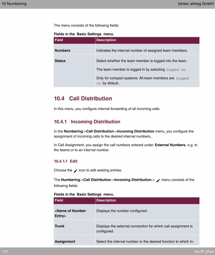
The menu consists of the following fields:
Fields in the Basic Settings menu.
Field Description
Numbers Indicates the internal number of assigned team members.
Status Select whether the team member is logged into the team.
The team member is logged in by selecting .
Only for compact systems: All team members are
by default..
10.4 Call Distribution
In this menu, you configure internal forwarding of all incoming calls.
10.4.1 Incoming Distribution
In the Numbering->Call Distribution->Incoming Distribution menu, you configure the
assignment of incoming calls to the desired internal numbers..
In Call Assignment, you assign the call numbers entered under External Numbers, e.g. to
the teams or to an internal number.
10.4.1.1 Edit
Choose the icon to edit existing entries.
The Numbering->Call Distribution->Incoming Distribution-> menu consists of the
following fields:
Fields in the Basic Settings menu.
Field Description
<Name of Number-
Entry>
Displays the number configured.
Trunk Displays the external connection for which call assignment is
configured.
Assignment Select the internal number or the desired function to which in-
10 Numbering bintec elmeg GmbH
166 be.IP plus

Field Description
coming calls shall be assigned via the line selected in Trunk .
Possible values:
• (default value): The internal team num-
ber is selected for assignment to a team.
•
•
•
•
•
Fields in the Internal Number and Rerouting Settings menu.
Field Description
Internal Number Only for Assignment =
Select the internal number to which incoming calls shall be as-
signed via the line selected in Trunk .
Rerouting Application Only for Assignment =
Select the desired redirect application to be assigned to the
number. You can configure redirect applications in the Applica-
tions->Rerouting->Rerouting Applications menu.
Active Variant (Day) Only for redirect application =
Select the redirect application variant to be currently enabled. If
a variant switch is set up via the calendar, this setting will be
switched back again at the appropriate time.
Possible values:
•
•
•
•
Fields in the Call Through Settings menu.
bintec elmeg GmbH 10 Numbering
be.IP plus 167

Field Description
Authorization Only for Assignment =
Define the authorisation for which the Call Through function
shall be released.
Possible values:
• : Dialling release occurs after matching
the entered number with the entry in the system phone book
or with the user's call number entries (Mobile Number and
Home Number).
• : Dialling release occurs after
matching the entered number with the entry in the system
phone book or with the user's call number entries (Mobile
Number and Home Number) AND PIN entry.
• : Dialling release occurs after PIN entry.
• : Dialling release occurs after
matching the entered number with the entry in the system
phone book or with the user's call number entries (Mobile
Number and Home Number) OR PIN entry.
PIN (6 Digit Numeric) Only for Authorization = , ,
The system checks the caller's authorisation for Call Through,
then activates a simulated external dialling tone for the call. Au-
thorisation is granted if the caller has entered the correct 6-digit
PIN.
Internal Number and
Rerouting Settings
Select the internal subscriber via which Call Through is to occur.
One of the system's telephone numbers is defined in the config-
uration for Call Through. An external caller using this telephone
number first hears the system's attention tone.
10 Numbering bintec elmeg GmbH
168 be.IP plus
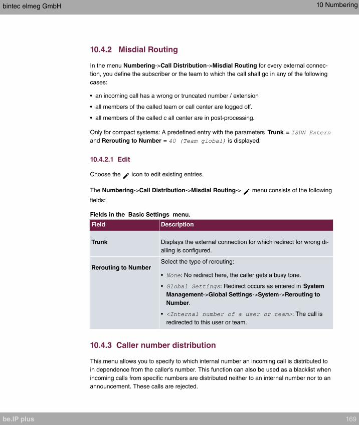
10.4.2 Misdial Routing
In the menu Numbering->Call Distribution->Misdial Routing for every external connec-
tion, you define the subscriber or the team to which the call shall go in any of the following
cases:
• an incoming call has a wrong or truncated number / extension
• all members of the called team or call center are logged off.
• all members of the called c all center are in post-processing.
Only for compact systems: A predefined entry with the parameters Trunk =
and Rerouting to Number = is displayed.
10.4.2.1 Edit
Choose the icon to edit existing entries.
The Numbering->Call Distribution->Misdial Routing-> menu consists of the following
fields:
Fields in the Basic Settings menu.
Field Description
Trunk Displays the external connection for which redirect for wrong di-
alling is configured.
Rerouting to NumberSelect the type of rerouting:
• : No redirect here, the caller gets a busy tone.
• : Redirect occurs as entered in System
Management->Global Settings->System->Rerouting to
Number.
• : The call is
redirected to this user or team.
10.4.3 Caller number distribution
This menu allows you to specify to which internal number an incoming call is distributed to
in dependence from the caller's number. This function can also be used as a blacklist when
incoming calls from specific numbers are distributed neither to an internal number nor to an
announcement. These calls are rejected.
bintec elmeg GmbH 10 Numbering
be.IP plus 169
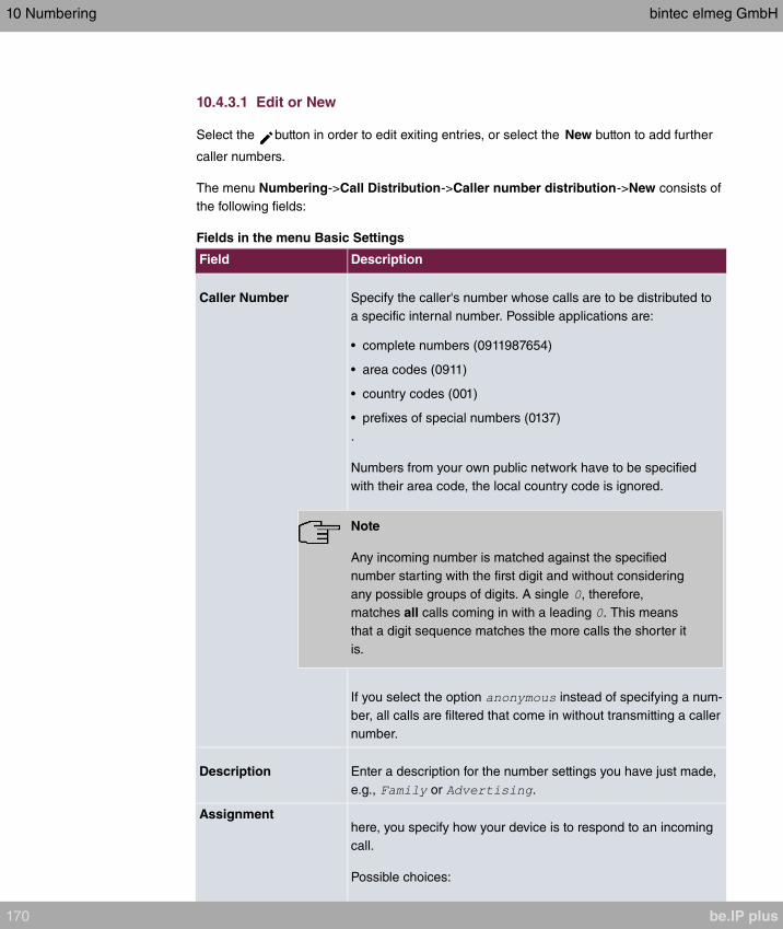
10.4.3.1 Edit or New
Select the button in order to edit exiting entries, or select the New button to add further
caller numbers.
The menu Numbering->Call Distribution->Caller number distribution->New consists of
the following fields:
Fields in the menu Basic Settings
Field Description
Caller Number Specify the caller's number whose calls are to be distributed to
a specific internal number. Possible applications are:
• complete numbers (0911987654)
• area codes (0911)
• country codes (001)
• prefixes of special numbers (0137)
.
Numbers from your own public network have to be specified
with their area code, the local country code is ignored.
Note
Any incoming number is matched against the specified
number starting with the first digit and without considering
any possible groups of digits. A single , therefore,
matches all calls coming in with a leading . This means
that a digit sequence matches the more calls the shorter it
is.
If you select the option instead of specifying a num-
ber, all calls are filtered that come in without transmitting a caller
number.
Description Enter a description for the number settings you have just made,
e.g., or .
Assignmenthere, you specify how your device is to respond to an incoming
call.
Possible choices:
10 Numbering bintec elmeg GmbH
170 be.IP plus

Field Description
• : The incoming call is not distributed, at all, and is re-
fused.
• : The call is distributed to an internal
number. If you choose this option, another card
(Assignment) is displayed that allows you to choose from the
available internal numbers.
• : The caller is played an announcement. You
can choose from the available announcements in the card As-
signment.
Note
If you want to assign more than one internal number to an incoming number, create
multiple entries for the same incoming number.
bintec elmeg GmbH 10 Numbering
be.IP plus 171
Chapter 11 Terminals
11.1 elmeg System Phones
In this menu, you perform the assignment of configured internal numbers to the terminals
and manage additional functions depending on the type of terminal.
The system telephone end devices (or DECT bases, respectively) are listed alphabetically
in the Description column. Click the column title of any other column to sort entries in as-
cending or descending order.
Connected telephones or DECT bases are automatically recognized and listed in the re-
spective summary; they can, however, also be manually configured before being connec-
ted to the system.
11.1.1 System Phone
A list of system telephones is displayed in the Terminals->elmeg System Phones->Sys-
tem Phone menu; it shows manually configured telephones as well as automatically detec-
ted ones.
The basic configuration is the same for all telephones, but there are differences in the
scope of service and configuration of several features (depending on the telephone type). If
you cannot use a specific feature with the selected telephone, it is not offered for configura-
tion.
Depending on its type, you can connect the system telephone to the internal ISDN, S0,
UP0 or Ethernet port. The system telephone offers typical system features in connection
with the PABX system. For example:
• Dialling from the system phone book
• Announcement and simplex operation with other system telephones on the system
• Function keys for control of system features (enable call options, login/logout in teams,
line keys, connection keys). The status of a feature can be indicated via LED's assigned
to individual function keys.
• Access to the system menu of the system. In this menu, advanced functions are offered
by the PABX system.
Choose the icon to edit existing entries.
As soon as a Description is entered for the system telephone and an entry is selected in
11 Terminals bintec elmeg GmbH
172 be.IP plus

the Internal Numbers field and copied with OK, the entry for that device is moved to the
upper part of the overview. To continue configuration, click the symbol again.
Choose the icon to copy existing entries. Copying an entry can prove useful if you wish
to create an entry only distinguished by a few parameters from an existing entry. In this
case, you copy the entry and modify the desired parameters.
Select the New button to create a new system telephone entry.
Note
Configuration modifications are transmitted to the system telephones at the earliest 30
seconds after confirming the modification with the Apply button.
11.1.1.1 General
In the Terminals->elmeg System Phones->System Phone->General menu, you perform
basic settings for a system telephone.
Telephone type
Various types of telephones can be configured.
If the system telephones are first configured in the system with type and serial number, the
system detects the system telephone after hook up to the connection. Then the configura-
tion created for this system telephone is transmitted by the system to the system tele-
phone.
Alternatively, you can create a system telephone in your PABX system, select the appropri-
ate telephone type, and assign an MSN. If you connect a telephone with default settings to
your PABX system, the telephone answers with the question for the language and the first
MSN. When you enter the language into the system telephone, and the MSN that you have
configured in the PABX system, the PABX system sends the configuration to the tele-
phone.
If the system telephone is removed, the system detects this and identifies the entry into the
system with a red arrow. If another system telephone of the same type is subsequently
connected, the system detects this and assigns the detected system telephone the corres-
ponding configuration. The system telephone thus receives the same configuration as its
predecessor, despite a different serial number. Only the first MSN must be identically
entered in the system telephone and the system.
The Terminals->elmeg System Phones->System Phone->General menu consists of the
following fields:
bintec elmeg GmbH 11 Terminals
be.IP plus 173
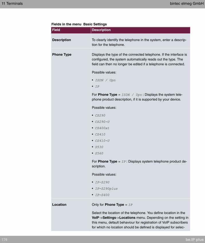
Fields in the menu Basic Settings
Field Description
Description To clearly identify the telephone in the system, enter a descrip-
tion for the telephone.
Phone Type Displays the type of the connected telephone. If the interface is
configured, the system automatically reads out the type. The
field can then no longer be edited if a telephone is connected.
Possible values:
•
•
For Phone Type = : Displays the system tele-
phone product description, if it is supported by your device.
Possible values:
•
•
•
•
•
•
•
For Phone Type = : Displays system telephone product de-
scription.
Possible values:
•
•
•
Location Only for Phone Type =
Select the location of the telephone. You define location in the
VoIP->Settings->Locations menu. Depending on the setting in
this menu, default behaviour for registration of VoIP subscribers
for which no location should be defined is displayed for selec-
11 Terminals bintec elmeg GmbH
174 be.IP plus
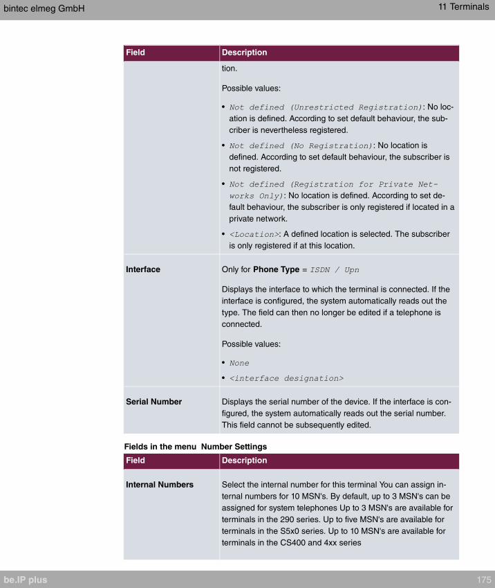
Field Description
tion.
Possible values:
• : No loc-
ation is defined. According to set default behaviour, the sub-
criber is nevertheless registered.
• : No location is
defined. According to set default behaviour, the subscriber is
not registered.
•
: No location is defined. According to set de-
fault behaviour, the subscriber is only registered if located in a
private network.
• : A defined location is selected. The subscriber
is only registered if at this location.
Interface Only for Phone Type =
Displays the interface to which the terminal is connected. If the
interface is configured, the system automatically reads out the
type. The field can then no longer be edited if a telephone is
connected.
Possible values:
•
•
Serial Number Displays the serial number of the device. If the interface is con-
figured, the system automatically reads out the serial number.
This field cannot be subsequently edited.
Fields in the menu Number Settings
Field Description
Internal Numbers Select the internal number for this terminal You can assign in-
ternal numbers for 10 MSN's. By default, up to 3 MSN's can be
assigned for system telephones Up to 3 MSN's are available for
terminals in the 290 series. Up to five MSN's are available for
terminals in the S5x0 series. Up to 10 MSN's are available for
terminals in the CS400 and 4xx series
bintec elmeg GmbH 11 Terminals
be.IP plus 175

Field Description
Please note that for proper operation of the telephone, at least
the first MSN must be entered in the system.
Possible values:
• : All configured internal
numbers are already in use. First configure another user with
additional numbers.
• : No internal number shall be as-
signed to this MSN.
• : Select one of the existing numbers of
the configured users.
Key extensions
The T400 key extension (available for CS4xx series telephones and for IP-S400) features
20 keys with LED's usable as function keys on two levels. The LED's are assigned to the
first key level. Two other LEDs are used to display additional information. You can connect
up to 3 key extensions in sequence (cascading) to your telephone. A plug power supply
unit must be used if using more than two key extensions.
The T400 /2 key extension (available for CS4xx series telephones and for IP-S400) fea-
tures 10 keys with LED's usable as function keys on two levels. The LED's are assigned to
the first key level. Two other LEDs are used to display additional information.
The T500 key extension (available for CS530 and S560 telephones) features 30 keys that
can be used as function keys on two levels. To the right of each key, two LED's indicate
which level is active. You can connect up to 3 key extensions in sequence (cascading) to
your telephone. A plug power supply unit is required from the first key extensions.
Fields in the menu Extensions
Field Description
Key Extension Module
1 - 3
Displays whether you're operating the system telephone with a
key extension module.
Possible values (each according to Phone Type):
•
•
•
•
11 Terminals bintec elmeg GmbH
176 be.IP plus

The menu Advanced Settings consists of the following fields:
Fields in the menu Codec Settings
Field Description
Codec ProfileSelect the codec profile to be used if the connection is over a
VoIP line. Codec profiles are configured in the VoIP->Settings-
>Codec Profiles menu.
Fields in the menu Further Settings
Field Description
Emergency Phone The system telephones of your system can be set up as emer-
gency telephones. You can immediately begin dialling extern-
ally, whether any external connections are active or not. If all
external connections are already in use, one of the active calls
is terminated and the connection is used for the emergency call.
If an emergency call is already being made, it is not interrupted.
You can use this performance feature regardless of the per-
formance feature priority for emergency calls.
The function is activated by selecting .
The function is disabled by default.
11.1.1.2 Settings
In the Terminals->elmeg System Phones->System Phone->Settings you can release
specific performance features and functions for this system telephone.
The Terminals->elmeg System Phones->System Phone->Settings menu consists of the
following fields:
Fields in the menu Basic Settings
Field Description
Display Language Select the display language for your telephone.
Possibe values:
•
• : Not for S530 and S560
•
•
bintec elmeg GmbH 11 Terminals
be.IP plus 177

Field Description
• : Not for S530 and S560
• : Not for S530 and S560
• : Not for S530 and S560
• : Not for S530 and S560
• : Not for S530 and S560
• : Not for S530 and S560
• : Not for S530 and S560
• : Not for S530 , S560 , CS290 , CS290-U , IP-S290 ,
IP-S290plus
• : Not for S530 , S560 , CS400, CS410 , CS410-U
, IP-S400
• : Not for S530 and S560
• : Not for S530 and S560
• : Not for S530 , S560 , CS290 , CS290-U , IP-S290 ,
IP-S290plus
Headset Support Not for S530 and S560.
Select whether the headset should automatically accept calls.
Note
If you wish to use a headset, you must configure a headset
key and a key for automatic call acceptance on your PABX
system. On the system telephone, you must select a head-
set type and enable the key for automatic call acceptance.
Call Waiting Select whether another call shall be supported for this tele-
phone through call waiting or a display notification.
The function is activated by selecting .
The function is disabled by default.
If Call Waiting is enabled, define for which calls you wish to al-
low call waiting.
Possible values:
11 Terminals bintec elmeg GmbH
178 be.IP plus
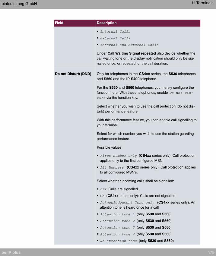
Field Description
•
•
•
Under Call Waiting Signal repeated also decide whether the
call waiting tone or the display notification should only be sig-
nalled once, or repeated for the call duration.
Do not Disturb (DND) Only for telephones in the CS4xx series, the S530 telephones
and S560 and the IP-S400 telephone.
For the S530 and S560 telephones, you merely configure the
function here. With these telephones, enable
via the function key.
Select whether you wish to use the call protection (do not dis-
turb) performance feature.
With this performance feature, you can enable call signalling to
your terminal.
Select for which number you wish to use the station guarding
performance feature.
Possible values:
• (CS4xx series only): Call protection
applies only to the first configured MSN.
• (CS4xx series only): Call protection applies
to all configured MSN's.
Select whether incoming calls shall be signalled:
• : Calls are signalled.
• (CS4xx series only): Calls are not signalled.
• (CS4xx series only): An
attention tone is heard once for a call
• (only S530 and S560)
• (only S530 and S560)
• (only S530 and S560)
• (only S530 and S560)
• (only S530 and S560)
bintec elmeg GmbH 11 Terminals
be.IP plus 179

The menu Advanced Settings consists of the following fields:
Fields in the menu Advanced Settings
Field Description
Status LED Select whether and, if so, which events should be signalled by
the system telephone status LED.
Possible values:
• : The status LED function is not used.
• : The status LED signals calls and new mes-
sages.
• : The status LED only signals new mes-
sages (MWI).
• (nur S5x0)
• (nur S5x0)
• (nur S5x0)
You can use the options ,
and individually, or combine them freely.
Directory Softkey Only for telephones in the CS4xx series
Select whether calls shall be made with the softkey entries from
the system phone book ( ) or from the telephone phone
book ( ).
Conversation Display Not for S5x0
Select which information shall be indicated in the system tele-
phone display during a call.
Possible values:
•
•
•
•
•
•
Default Signalling dur- Select whether DTMF signals or keypad functions shall be
11 Terminals bintec elmeg GmbH
180 be.IP plus
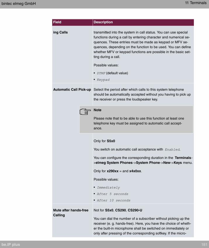
Field Description
ing Calls transmitted into the system in call status. You can use special
functions during a call by entering character and numerical se-
quences. These entries must be made as keypad or MFV se-
quences, depending on the function to be used. You can define
whether MFV or keypad functions are possible in the basic set-
ting during a call.
Possible values:
• (default value)
•
Automatic Call Pick-up Select the period after which calls to this system telephone
should be automatically accepted without you having to pick up
the receiver or press the loudspeaker key.
Note
Please note that to be able to use this function at least one
telephone key must be assigned to automatic call accept-
ance.
Only for S5x0
You switch on automatic call acceptance with .
You can configure the corresponding duration in the Terminals-
>elmeg System Phones->System Phone->New->Keys menu.
Only for x290xx = and x4x0xx.
Possible values:
•
•
•
Mute after hands-free
Calling
Not for S5x0, CS290, CS290-U
You can dial the number of a subscriber without picking up the
receiver (e. g. hands-free). Here, you have the choice of wheth-
er the built-in microphone shall be switched on immediately or
only after pressing of the corresponding softkey. If the micro-
bintec elmeg GmbH 11 Terminals
be.IP plus 181
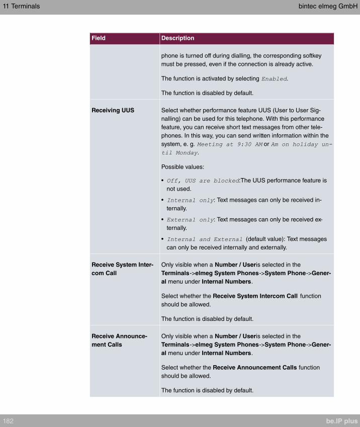
Field Description
phone is turned off during dialling, the corresponding softkey
must be pressed, even if the connection is already active.
The function is activated by selecting .
The function is disabled by default.
Receiving UUS Select whether performance feature UUS (User to User Sig-
nalling) can be used for this telephone. With this performance
feature, you can receive short text messages from other tele-
phones. In this way, you can send written information within the
system, e. g. or
.
Possible values:
• :The UUS performance feature is
not used.
• : Text messages can only be received in-
ternally.
• : Text messages can only be received ex-
ternally.
• (default value): Text messages
can only be received internally and externally.
Receive System Inter-
com Call
Only visible when a Number / Useris selected in the
Terminals->elmeg System Phones->System Phone->Gener-
al menu under Internal Numbers.
Select whether the Receive System Intercom Call function
should be allowed.
The function is disabled by default.
Receive Announce-
ment Calls
Only visible when a Number / Useris selected in the
Terminals->elmeg System Phones->System Phone->Gener-
al menu under Internal Numbers.
Select whether the Receive Announcement Calls function
should be allowed.
The function is disabled by default.
11 Terminals bintec elmeg GmbH
182 be.IP plus

11.1.1.3 Keys / T400 / T400/2 / T500
The menu Terminals->elmeg System Phones->System Phone->Keys displays the con-
figuration of your system telephone's keys.
Your telephone features several function keys to which you can assign various functions on
two levels The functions that can be programmed on the keys vary from telephone to tele-
phone.
Every function key with automatic LED functions (e. g. connection keys, line keys) can only
be programmed once per system (telephone and key extensions).
Values in the list Keys
Field Description
Key Displays the name of the key.
Label Description Displays the configured key name. This appears on the labelling
page (label strips).
Key Type Displays the key type.
Settings Displays the additional settings with a summary
Print allows you to print out a label sheet for the description field of your system phone or
key extension.
Edit
Choose the icon to edit existing entries. In the pop-up menu, you configure the func-
tions of your system telephone keys.
You can use the following functions with system telephones:
• : You can perform an internal or external call so that your system
telephone transmits a specific number (MSN) to the caller. This number (MSN) has to be
configured on your system telephone. If the LED is active, there is an active connection
via this key.
• : You can store a number on each function key. External num-
bers have to be prefixed by the exchange code if has
been configured for your Class of Serviceon the telephone.
• : You can store a DTMF sequence on every function key.
• : You can store a keypad sequence on every function
key.
bintec elmeg GmbH 11 Terminals
be.IP plus 183
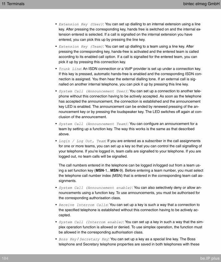
• : You can set up dialling to an internal extension using a line
key. After pressing the corresponding key, hands free is switched on and the internal ex-
tension entered is selected. If a call is signalled on the internal extension you have
entered, you can pick this up by pressing the line key.
• : You can set up dialling to a team using a line key. After
pressing the corresponding key, hands-free is activated and the entered team is called
according to its enabled call option. If a call is signalled for the entered team, you can
pick it up by pressing this connection key.
• : An ISDN connection or a VoIP provider is set up under a connection key.
If this key is pressed, automatic hands-free is enabled and the corresponding ISDN con-
nection is assigned. You then hear the external dialling tone. If an external call is sig-
nalled on another internal telephone, you can pick it up by pressing this line key.
• : You can set up a connection to another tele-
phone without this connection having to be actively accepted. As soon as the telephone
has accepted the announcement, the connection is established and the announcement
key LED is enabled. The announcement can be ended by renewed pressing of the an-
nouncement key or by pressing the loudspeaker key. The LED switches off again at con-
clusion of the announcement.
• : You can configure an announcement for a
team by setting up a function key. The way this works is the same as that described
above.
• : If you are entered as a subscriber in the call assignments
for one or more teams, you can set up a key so that you can control the call signalling of
your telephone. If you're logged in, team calls are signalled to your telephone. If you are
logged out, no team calls will be signalled.
The call numbers entered in the telephone can be logged in/logged out from a team us-
ing a set function key (MSN-1... MSN-9). Before entering a team number, you must select
the telephone call number index (MSN) that is entered in the corresponding team call as-
signments.
• : You can also selectively deny or allow an-
nouncements using a function key. To use announcements, you must be authorised for
the corresponding authorisation class.
• : You can set up a key is such a way that a connection to
the specified telephone is established without this connection having to be actively ac-
cepted.
• : You can set up a key in such a way that the sim-
plex operation function is allowed or denied. To use simplex operation, the function must
be allowed in the corresponding authorisation class.
• / : You can set up a key as a special line key. The Boss
telephone and Secretary telephone properties are saved in both telephones with these
11 Terminals bintec elmeg GmbH
184 be.IP plus
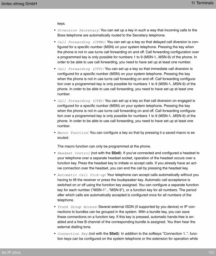
keys.
• : You can set up a key in such a way that incoming calls to the
Boss telephone are automatically routed to the Secretary telephone.
• : You can set up a key so that delayed call diversion is con-
figured for a specific number (MSN) on your system telephone. Pressing the key when
the phone is not in use turns call forwarding on and off. Call forwarding configuration over
a programmed key is only possible for numbers 1 to 9 (MSN-1...MSN-9) of the phone. In
order to be able to use call forwarding, you need to have set up at least one number.
• : You can set up a key so that immediate call diversion is
configured for a specific number (MSN) on your system telephone. Pressing the key
when the phone is not in use turns call forwarding on and off. Call forwarding configura-
tion over a programmed key is only possible for numbers 1 to 9 (MSN-1...MSN-9) of the
phone. In order to be able to use call forwarding, you need to have set up at least one
number.
• : You can set up a key so that call diversion on engaged is
configured for a specific number (MSN) on your system telephone. Pressing the key
when the phone is not in use turns call forwarding on and off. Call forwarding configura-
tion over a programmed key is only possible for numbers 1 to 9 (MSN-1...MSN-9) of the
phone. In order to be able to use call forwarding, you need to have set up at least one
number.
• : You can configure a key so that by pressing it a saved macro is ex-
ecuted.
The macro function can only be programmed at the phone.
• (not with the S5x0): If you've connected and configured a headset to
your telephone over a separate headset socket, operation of the headset occurs over a
function key. Press the headset key to initiate or accept calls. If you already have an act-
ive connection over the headset, you can end the call by pressing the headset key.
• : Your telephone can accept calls automatically without you
having to lift the receiver or press the loudspeaker key. Automatic call acceptance is
switched on or off using the function key assigned. You can configure a separate function
key for each number ("MSN-1"..."MSN-9"), or a function key for all numbers. The period
after which calls are automatically accepted is configured once for all numbers of the
telephone.
• : Several external ISDN (if supported by you device) or IP con-
nections to bundles can be grouped in the system. With a bundle key, you can save
these connections on a function key. If this key is pressed, automatic hands-free is en-
abled and a free B channel of the corresponding bundle is assigned. You then hear the
external dialling tone.
• (not with the S5x0): In addition to the softkeys "Connection 1..", func-
tion keys can be configured on the system telephone or the extension for operation while
bintec elmeg GmbH 11 Terminals
be.IP plus 185
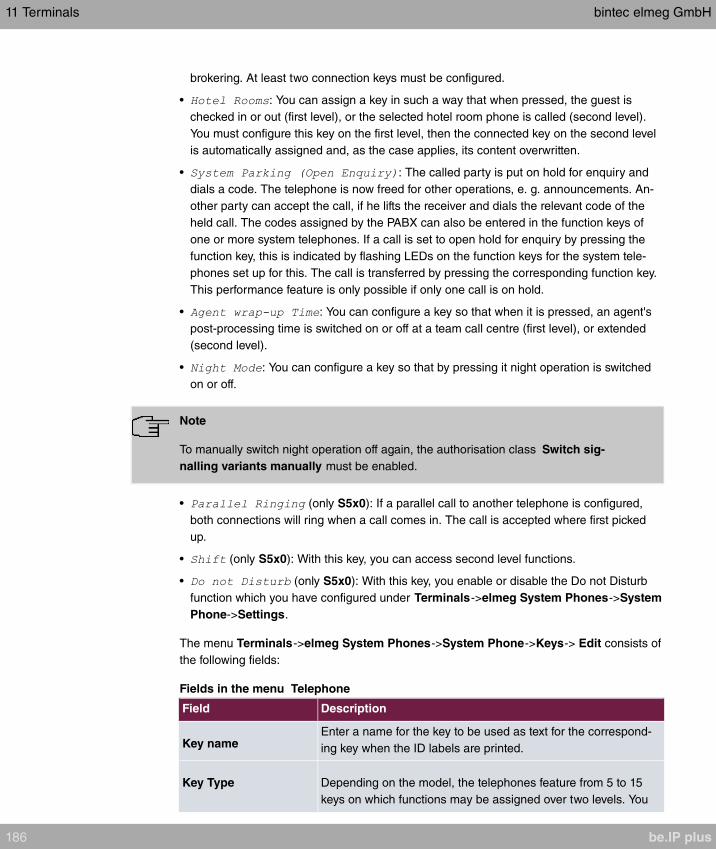
brokering. At least two connection keys must be configured.
• : You can assign a key in such a way that when pressed, the guest is
checked in or out (first level), or the selected hotel room phone is called (second level).
You must configure this key on the first level, then the connected key on the second level
is automatically assigned and, as the case applies, its content overwritten.
• : The called party is put on hold for enquiry and
dials a code. The telephone is now freed for other operations, e. g. announcements. An-
other party can accept the call, if he lifts the receiver and dials the relevant code of the
held call. The codes assigned by the PABX can also be entered in the function keys of
one or more system telephones. If a call is set to open hold for enquiry by pressing the
function key, this is indicated by flashing LEDs on the function keys for the system tele-
phones set up for this. The call is transferred by pressing the corresponding function key.
This performance feature is only possible if only one call is on hold.
• : You can configure a key so that when it is pressed, an agent's
post-processing time is switched on or off at a team call centre (first level), or extended
(second level).
• : You can configure a key so that by pressing it night operation is switched
on or off.
Note
To manually switch night operation off again, the authorisation class Switch sig-
nalling variants manually must be enabled.
• (only S5x0): If a parallel call to another telephone is configured,
both connections will ring when a call comes in. The call is accepted where first picked
up.
• (only S5x0): With this key, you can access second level functions.
• (only S5x0): With this key, you enable or disable the Do not Disturb
function which you have configured under Terminals->elmeg System Phones->System
Phone->Settings.
The menu Terminals->elmeg System Phones->System Phone->Keys-> Edit consists of
the following fields:
Fields in the menu Telephone
Field Description
Key nameEnter a name for the key to be used as text for the correspond-
ing key when the ID labels are printed.
Key Type Depending on the model, the telephones feature from 5 to 15
keys on which functions may be assigned over two levels. You
11 Terminals bintec elmeg GmbH
186 be.IP plus
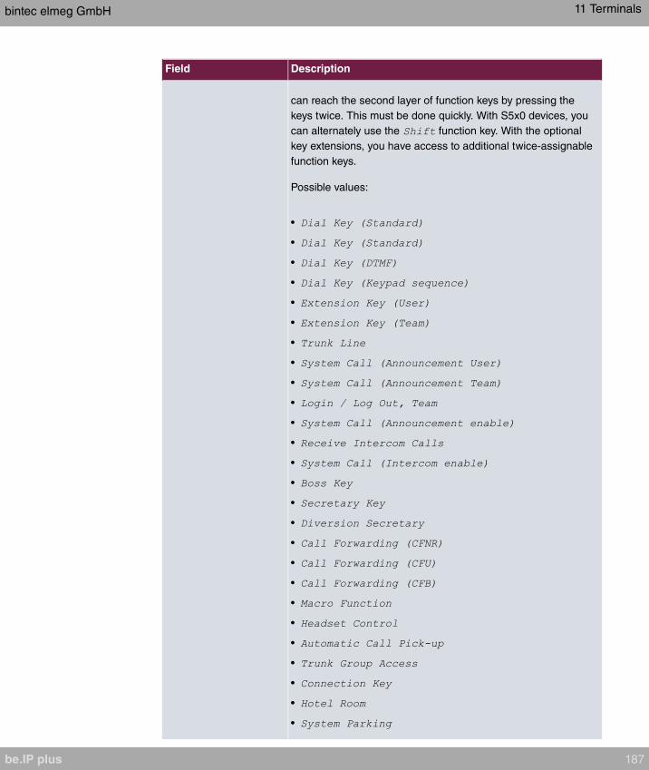
Field Description
can reach the second layer of function keys by pressing the
keys twice. This must be done quickly. With S5x0 devices, you
can alternately use the function key. With the optional
key extensions, you have access to additional twice-assignable
function keys.
Possible values:
•
•
•
•
•
•
•
•
•
•
•
•
•
•
•
•
•
•
•
•
•
•
•
•
•
•
bintec elmeg GmbH 11 Terminals
be.IP plus 187
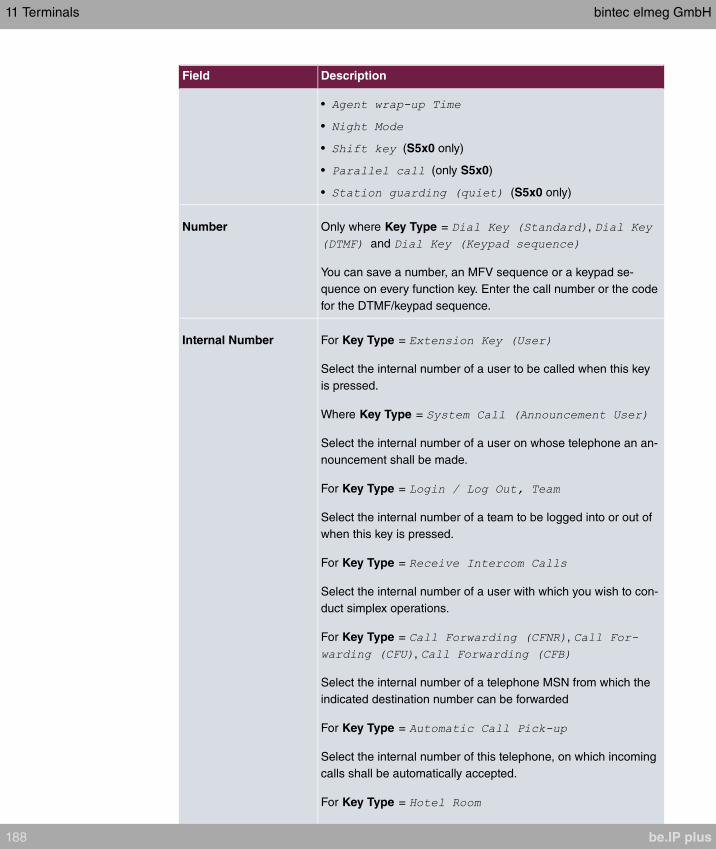
Field Description
•
•
• (S5x0 only)
• (only S5x0)
• (S5x0 only)
Number Only where Key Type = ,
and
You can save a number, an MFV sequence or a keypad se-
quence on every function key. Enter the call number or the code
for the DTMF/keypad sequence.
Internal Number For Key Type =
Select the internal number of a user to be called when this key
is pressed.
Where Key Type =
Select the internal number of a user on whose telephone an an-
nouncement shall be made.
For Key Type =
Select the internal number of a team to be logged into or out of
when this key is pressed.
For Key Type =
Select the internal number of a user with which you wish to con-
duct simplex operations.
For Key Type = ,
,
Select the internal number of a telephone MSN from which the
indicated destination number can be forwarded
For Key Type =
Select the internal number of this telephone, on which incoming
calls shall be automatically accepted.
For Key Type =
11 Terminals bintec elmeg GmbH
188 be.IP plus

Field Description
Select the internal number of a hotel guest.
For Key Type =
Select the internal number of a user whose post-processing
time shall be modified at regular intervals when this key is
pressed.
For Key Type =
Select the internal number of a user whose phone should also
ring when a call goes in to you.
For Key Type =
Select that number of your telephone you intend to use.
Automatic Call Pick-up For Key Type =
Select when a call shall be automatically accepted by the
entered internal subscriber.
Possible values:
• : The call is immediately and automatically ac-
cepted.
• : The call is automatically accepted after
5 seconds.
• : The call is automatically accepted after
10 seconds.
• (only S5x0): The call is automatically
accepted after 15 seconds.
• (only S5x0): The call is automatically
accepted after 20 seconds.
• (only S5x0): The call is not automatically accepted.
Team For Key Type =
Select the internal number of a team to be called when this key
is pressed.
Where Key Type =
Select the internal number of a team on whose telephone an
bintec elmeg GmbH 11 Terminals
be.IP plus 189
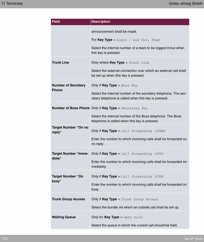
Field Description
announcement shall be made.
For Key Type =
Select the internal number of a team to be logged in/out when
this key is pressed.
Trunk Line Only where Key Type =
Select the external connection over which an external call shall
be set up when this key is pressed.
Number of Secretary
Phone
Only if Key Type =
Select the internal number of the secretary telephone. The sec-
retary telephone is called when this key is pressed.
Number of Boss Phone Only if Key Type =
Select the internal number of the Boss telephone. The Boss
telephone is called when this key is pressed.
Target Number "On no
reply" Only if Key Type =
Enter the number to which incoming calls shall be forwarded on
no reply .
Target Number "Imme-
diate"
Only if Key Type =
Enter the number to which incoming calls shall be forwarded im-
mediately.
Target Number "On
busy"
Only if Key Type =
Enter the number to which incoming calls shall be forwarded on
busy.
Trunk Group Access Only if Key Type =
Select the bundle via which an outside call shall be set up.
Waiting Queue Only for Key Type =
Select the queue in which the current call should be held.
11 Terminals bintec elmeg GmbH
190 be.IP plus
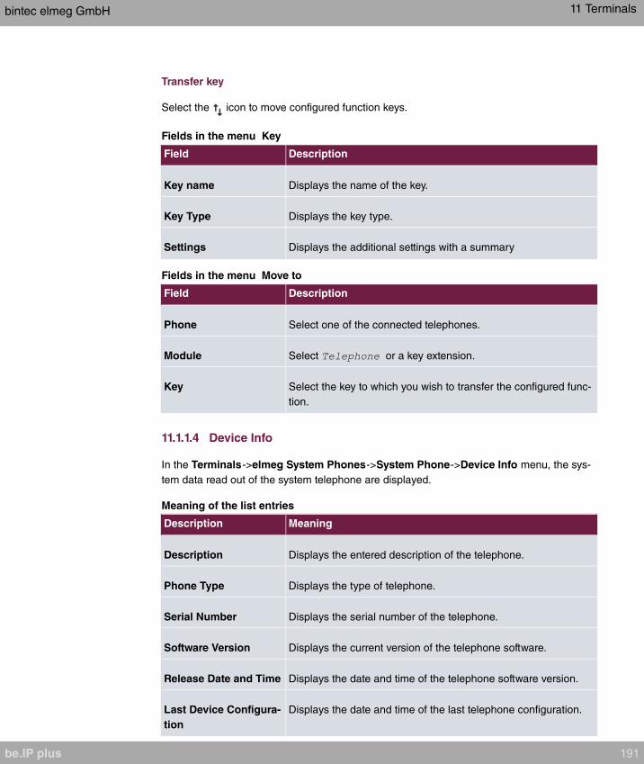
Transfer key
Select the icon to move configured function keys.
Fields in the menu Key
Field Description
Key name Displays the name of the key.
Key Type Displays the key type.
Settings Displays the additional settings with a summary
Fields in the menu Move to
Field Description
Phone Select one of the connected telephones.
Module Select or a key extension.
Key Select the key to which you wish to transfer the configured func-
tion.
11.1.1.4 Device Info
In the Terminals->elmeg System Phones->System Phone->Device Info menu, the sys-
tem data read out of the system telephone are displayed.
Meaning of the list entries
Description Meaning
Description Displays the entered description of the telephone.
Phone Type Displays the type of telephone.
Serial Number Displays the serial number of the telephone.
Software Version Displays the current version of the telephone software.
Release Date and Time Displays the date and time of the telephone software version.
Last Device Configura-
tion
Displays the date and time of the last telephone configuration.
bintec elmeg GmbH 11 Terminals
be.IP plus 191
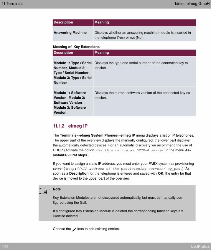
Description Meaning
Answering Machine Displays whether an answering machine module is inserted in
the telephone (Yes) or not (No).
Meaning of Key Extensions
Description Meaning
Module 1: Type / Serial
Number, Module 2:
Type / Serial Number,
Module 3: Type / Serial
Number
Displays the type and serial number of the connected key ex-
tension.
Module 1: Software
Version, Module 2:
Software Version ,
Module 3: Software
Version
Displays the current software version of the connected key ex-
tension.
11.1.2 elmeg IP
The Terminals->elmeg System Phones->elmeg IP menu displays a list of IP telephones.
The upper part of the overview displays the manually configured, the lower part displays
the automatically detected devices. For an automatic discovery we recommend the use of
DHCP. (Activate the option in the menu As-
sistants->First steps.)
If you want to assign a static IP address, you must enter your PABX system as provisioning
server ( ). As
soon as a Description for the telephone is entered and saved with OK, the entry for that
device is moved to the upper part of the overview.
Note
Key Extension Modules are not discovered automatically, but must be manually con-
figured using the GUI.
If a configured Key Extension Module is deleted the corresponding function keys are
likewise deleted.
Choose the icon to edit existing entries.
11 Terminals bintec elmeg GmbH
192 be.IP plus
After a short time, the icons and are displayed for this device.
After clicking the Apply button it takes several seconds until the changes have been trans-
mitted to the respective IP telephone.
Choose the symbol in order to copy an existing entry. This can be useful if you intend to
create an entry that differs only in a few parameters from the already existing entry. In this
case, copy the entry and change only the desired paramaters.
Select the button to go to the elmeg IP telephone user interface administrator page.
This is described in the telephone user guide.
Select the New button to manually set up a new IP end device.
Employ automatic provisioning in order to have your PABX system transmit basic tele-
phony parameters to the IP telephones. When using the assistent First steps activate the
option for the field Transmit Provisioning Server for in the Assist-
ants->First steps->Advanced Settings->Add section. Alternatively, you can create a new
entry in the menu Local Services->DHCP Server->DHCP Configuration->New->Ad-
vanced Settings->DHCP Options and set the fields Option =
and Value =
.
To register the handsets you first set the base station to login mode. Then you perform the
registering of the handsets on the handests themselves. To configure the base station in
any more detail, you need to use the DECT system's web configurator.
Select the button to trigger an update of the device's provisioning. If the update is suc-
cessful, the updated value displays in the Last seen column within 10 seconds.
Note
If you wish to test whether your base station is correctly configured and accessible, se-
lect the button and check whether an updated value is displayed within 10 seconds
in the Last seen column.
11.1.2.1 General
In the menu Terminals->elmeg System Phones->elmeg IP->General, you make the ba-
sic settings for an IP telephone.
The menu consists of the following fields:
Fields in the menu Basic Settings
bintec elmeg GmbH 11 Terminals
be.IP plus 193
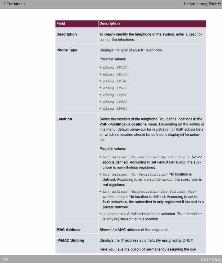
Field Description
Description To clearly identify the telephone in the system, enter a descrip-
tion for the telephone.
Phone Type Displays the type of your IP telephone.
Possible values:
•
•
•
•
•
•
•
Location Select the location of the telephone. You define locations in the
VoIP->Settings->Locations menu. Depending on the setting in
this menu, default behaviour for registration of VoIP subscribers
for which no location should be defined is displayed for selec-
tion.
Possible values:
• : No loc-
ation is defined. According to set default behaviour, the sub-
criber is nevertheless registered.
• : No location is
defined. According to set default behaviour, the subscriber is
not registered.
•
: No location is defined. According to set de-
fault behaviour, the subscriber is only registered if located in a
private network.
• : A defined location is selected. The subscriber
is only registered if at this location.
MAC Address Shows the MAC address of the telephone.
IP/MAC Binding Displays the IP address automatically assigned by DHCP.
Here you have the option of permanently assigning the dis-
11 Terminals bintec elmeg GmbH
194 be.IP plus
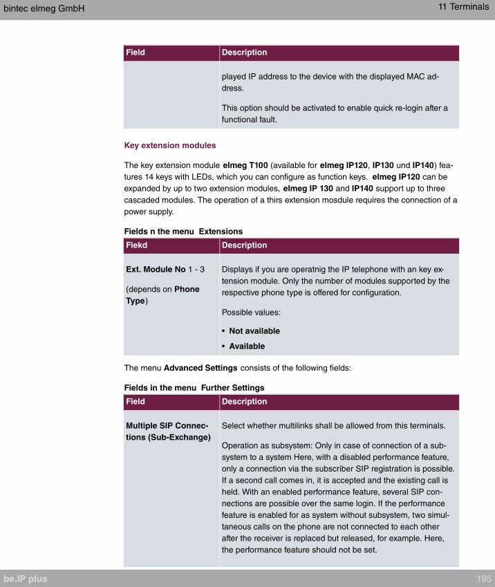
Field Description
played IP address to the device with the displayed MAC ad-
dress.
This option should be activated to enable quick re-login after a
functional fault.
Key extension modules
The key extension module elmeg T100 (available for elmeg IP120, IP130 und IP140) fea-
tures 14 keys with LEDs, which you can configure as function keys. elmeg IP120 can be
expanded by up to two extension modules, elmeg IP 130 and IP140 support up to three
cascaded modules. The operation of a thirs extension mosdule requires the connection of a
power supply.
Fields n the menu Extensions
Fiekd Description
Ext. Module No 1 - 3
(depends on Phone
Type)
Displays if you are operatnig the IP telephone with an key ex-
tension module. Only the number of modules supported by the
respective phone type is offered for configuration.
Possible values:
• Not available
• Available
The menu Advanced Settings consists of the following fields:
Fields in the menu Further Settings
Field Description
Multiple SIP Connec-
tions (Sub-Exchange)
Select whether multilinks shall be allowed from this terminals.
Operation as subsystem: Only in case of connection of a sub-
system to a system Here, with a disabled performance feature,
only a connection via the subscriber SIP registration is possible.
If a second call comes in, it is accepted and the existing call is
held. With an enabled performance feature, several SIP con-
nections are possible over the same login. If the performance
feature is enabled for as system without subsystem, two simul-
taneous calls on the phone are not connected to each other
after the receiver is replaced but released, for example. Here,
the performance feature should not be set.
bintec elmeg GmbH 11 Terminals
be.IP plus 195

Field Description
The function is activated by selecting .
The function is disabled by default.
No Hold and Retrieve The performance features hold a call and retrieve a held call are
not available on certain telephones.
The function is activated by selecting .
The function is disabled by default.
Fields in the menu Codec Settings
Field Description
Codec ProfileSelect the Codec profile to be used. Codec profiles are con-
figured in the VoIP->Settings->Codec Profiles menu.
Video Select if calls between IP telephones are to support the trans-
mission of video data. Video transmission can only be negoti-
ated between the participants if both support this feature.
SRTP Select if calls via this SIP provider may be secured with SRTP
(Secure Real-Time Transport Protocol).
11.1.2.2 Numbers
In the menu Terminals->elmeg System Phones->elmeg IP->Numbers you assign an IP
telephone up to twelve internal phone numbers using Add.
The available internal phone numbers are created under Numbering->User
Settings->Users->New.
You can delete assigned numbers from the list with .
Values in the list Number Settings
Field Description
Connections Nr. Shows the serial number of the connection.
Internal Number Displays the assigned internal number.
Displayed Description Displays the description that will be displayed on the IP tele-
phone's display.
User Displays the user's name.
11 Terminals bintec elmeg GmbH
196 be.IP plus

11.1.2.3 Keys / T100
The menu Terminals->elmeg System Phones->elmeg IP->Keys displays the configura-
tion of your system telephone's keys.
Note
You can configure the key assigment either through your PABX system or on the tele-
phone itself. We recommend using your PABX system for this, since it overwrites the
telephone configuration.
You can avoid the overwriting for individual keys that have already been configured on
the telephone by choosing on the PABX system.
Your telephone is equipped with several function keys that allow the assignment of different
functions. The functions available for programming are different across different types of
telephones.
Values in the list Keys
Field Description
Key Displays the name of the key.
Label Description Displays the configured key name. This appears on the labelling
page (label strips).
Key Type Displays the key type.
Settings Displays the additional settings with a summary
Print allows you to print out a label sheet for the description field of your system phone or
key extension.
Edit
Choose the icon to edit existing entries. In the pop-up menu, you configure the func-
tions of your system telephone keys.
You can use the following functions with system telephones:
• : You can store a number on each function key. External num-
bers have to be prefixed by the exchange code if has
been configured for your Class of Service on the telephone.
bintec elmeg GmbH 11 Terminals
be.IP plus 197

• : You can store a DTMF sequence on every function key.
• : You can set up dialling to an internal extension using a line
key. After pressing the corresponding key, hands free is switched on and the internal ex-
tension entered is selected. If a call is signalled on the internal extension you have
entered, you can pick this up by pressing the line key.
• : Assigns a specific connection (i.e. a specific SIP account) to the
function key. You can use this key to initiate a call via this connection, or you can accept
a call coming in via this connection. The key flashes if a call is received, it is lit if the con-
nection is busy. Select the desired connection. All configured connections are available.
Configure SIP accounts exclusively on your PABX system.
• : Assigns activating or deactivating a call forwarding that
has been configured on the telephone. You can only store a single call forwarding on the
device; it is applied to all calls.
• : The called extension enters an enquiry and dials
a code. The telephone is now open for additional operations like e.g.an announcement. A
second subscriber can accept the call by picking up the receiver and dialing the code cor-
responding to the call. The codes are determined by the PABX, but can also be assigned
to the functions keys of one or more system phones. If a call is put into open enquiry by
pressing a function key, this is indicated by the flashing of the respective function key
LED on all system phones with a corresponding configuration. Pressing the function key
accepts the call. This function is only available if a call has been parked.
• : If you are entered as a subscriber in the call assignments
for one or more teams, you can set up a key so that you can control the call signalling of
your telephone. If you're logged in, team calls are signalled to your telephone. If you are
logged out, no team calls will be signalled.
The call numbers entered in the telephone can be logged in/logged out from a team us-
ing a set function key (MSN-1... MSN-9). Before entering a team number, you must select
the telephone call number index (MSN) that is entered in the corresponding team call as-
signments.
• : You can set up a key so that delayed call diversion is con-
figured for a specific number (MSN) on your system telephone. Pressing the key when
the phone is not in use turns call forwarding on and off. Call forwarding configuration over
a programmed key is only possible for numbers 1 to 9 (MSN-1...MSN-9) of the phone. In
order to be able to use call forwarding, you need to have set up at least one number.
• : You can set up a key so that immediate call diversion is
configured for a specific number (MSN) on your system telephone. Pressing the key
when the phone is not in use turns call forwarding on and off. Call forwarding configura-
tion over a programmed key is only possible for numbers 1 to 9 (MSN-1...MSN-9) of the
phone. In order to be able to use call forwarding, you need to have set up at least one
number.
• : You can set up a key so that call diversion on engaged is
11 Terminals bintec elmeg GmbH
198 be.IP plus
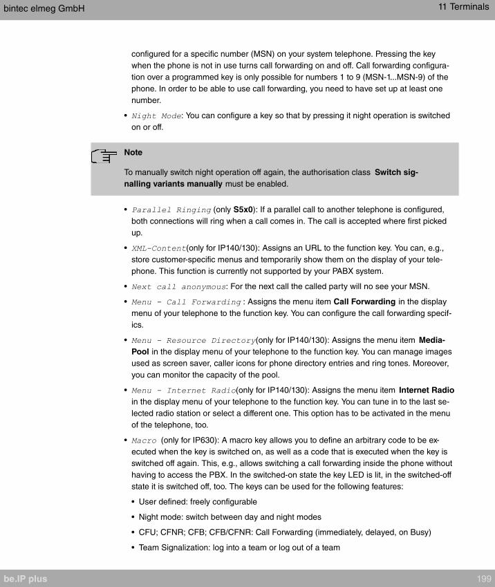
configured for a specific number (MSN) on your system telephone. Pressing the key
when the phone is not in use turns call forwarding on and off. Call forwarding configura-
tion over a programmed key is only possible for numbers 1 to 9 (MSN-1...MSN-9) of the
phone. In order to be able to use call forwarding, you need to have set up at least one
number.
• : You can configure a key so that by pressing it night operation is switched
on or off.
Note
To manually switch night operation off again, the authorisation class Switch sig-
nalling variants manually must be enabled.
• (only S5x0): If a parallel call to another telephone is configured,
both connections will ring when a call comes in. The call is accepted where first picked
up.
• (only for IP140/130): Assigns an URL to the function key. You can, e.g.,
store customer-specific menus and temporarily show them on the display of your tele-
phone. This function is currently not supported by your PABX system.
• : For the next call the called party will no see your MSN.
• : Assigns the menu item Call Forwarding in the display
menu of your telephone to the function key. You can configure the call forwarding specif-
ics.
• (only for IP140/130): Assigns the menu item Media-
Pool in the display menu of your telephone to the function key. You can manage images
used as screen saver, caller icons for phone directory entries and ring tones. Moreover,
you can monitor the capacity of the pool.
• (only for IP140/130): Assigns the menu item Internet Radio
in the display menu of your telephone to the function key. You can tune in to the last se-
lected radio station or select a different one. This option has to be activated in the menu
of the telephone, too.
• (only for IP630): A macro key allows you to define an arbitrary code to be ex-
ecuted when the key is switched on, as well as a code that is executed when the key is
switched off again. This, e.g., allows switching a call forwarding inside the phone without
having to access the PBX. In the switched-on state the key LED is lit, in the switched-off
state it is switched off, too. The keys can be used for the following features:
• User defined: freely configurable
• Night mode: switch between day and night modes
• CFU; CFNR; CFB; CFB/CFNR: Call Forwarding (immediately, delayed, on Busy)
• Team Signalization: log into a team or log out of a team
bintec elmeg GmbH 11 Terminals
be.IP plus 199
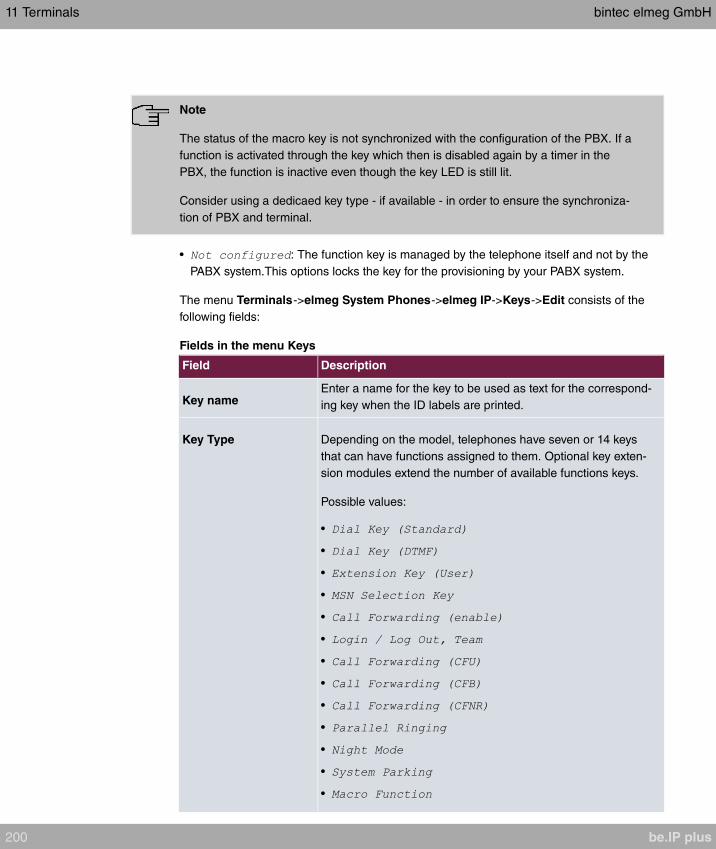
Note
The status of the macro key is not synchronized with the configuration of the PBX. If a
function is activated through the key which then is disabled again by a timer in the
PBX, the function is inactive even though the key LED is still lit.
Consider using a dedicaed key type - if available - in order to ensure the synchroniza-
tion of PBX and terminal.
• : The function key is managed by the telephone itself and not by the
PABX system.This options locks the key for the provisioning by your PABX system.
The menu Terminals->elmeg System Phones->elmeg IP->Keys->Edit consists of the
following fields:
Fields in the menu Keys
Field Description
Key nameEnter a name for the key to be used as text for the correspond-
ing key when the ID labels are printed.
Key Type Depending on the model, telephones have seven or 14 keys
that can have functions assigned to them. Optional key exten-
sion modules extend the number of available functions keys.
Possible values:
•
•
•
•
•
•
•
•
•
•
•
•
•
11 Terminals bintec elmeg GmbH
200 be.IP plus

Field Description
•
•
•
•
•
•
Internal MSN Only for Key Type = ,
, ,
or
You can select one of the internal MSNs configured in the menu
Terminals->elmeg System Phones->elmeg IP->Numbers.
Number Only for Key Type = or
You can save a number or a DTMF sequence to any function
kye. Specify the number or the characters for the DTMF se-
quence.
Internal Number For Key Type =
Select the internal number of the subscriber that is to be called
when pressing this key.
For Key Type = : Select the intern-
al number of the terminal that is to be logged in to or out of the
team.
For Key Type = ,
und : Select the in-
ternal number the incoming calls of which are to be forwarded.
For Key Type = : Select the internal num-
ber the incoming calls of which are to trigger a parallel ringing.
Parallel ringing is configured in the menu Numbering->User
Settings Parallel Ringing.
Team Only for Key Type = :
Select the calling number of the team, the terminal is to be
looged in to or out of.
bintec elmeg GmbH 11 Terminals
be.IP plus 201

Field Description
Pick-Up Code Only for Key Type =
The code that is required for the busy lamp field to allow you
picking up a call on an IP telephone when the LED is flashing.
The default value is .
Waiting Queue Only for Key Type =
Select the waiting queue to which the currect connection is to
be added.
Macro Function Only for Key Type =
The keys can be used for the following features:
• : Freely configurable
• : Switch between day and night modes
• : Call Forwarding
(immediately, delayed, on Busy)
• : You can log in to a team or log out
of a team.
On Code Only forMacro Function =
Define an arbitrary code to be executed when the key is
switched on.
Off Code Only forMacro Function =
Define an arbitrary code to be executed when the key is
switched off.
URL Only for Key Type =
For this function you can store the URL to a server which hosts
the desired information. This function is currently not supported
by your PABX system.
Transfer key
Select the icon to move configured function keys.
11 Terminals bintec elmeg GmbH
202 be.IP plus
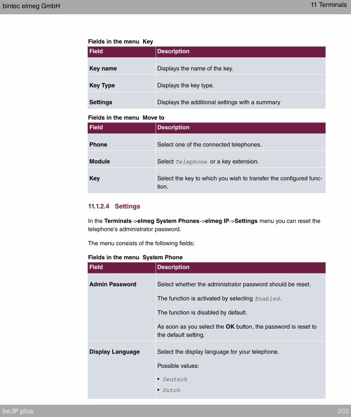
Fields in the menu Key
Field Description
Key name Displays the name of the key.
Key Type Displays the key type.
Settings Displays the additional settings with a summary
Fields in the menu Move to
Field Description
Phone Select one of the connected telephones.
Module Select or a key extension.
Key Select the key to which you wish to transfer the configured func-
tion.
11.1.2.4 Settings
In the Terminals->elmeg System Phones->elmeg IP->Settings menu you can reset the
telephone's administrator password.
The menu consists of the following fields:
Fields in the menu System Phone
Field Description
Admin Password Select whether the administrator password should be reset.
The function is activated by selecting .
The function is disabled by default.
As soon as you select the OK button, the password is reset to
the default setting.
Display Language Select the display language for your telephone.
Possible values:
•
•
bintec elmeg GmbH 11 Terminals
be.IP plus 203

Field Description
•
•
•
•
•
•
•
•
•
•
11.1.3 elmeg DECT
The menu Terminals->elmeg System Phones->elmeg DECT displays the base stations
of the connected DECT single-cell and multi-cell systems.
All base stations that are connected are automatically detected and listed in the lower part
of the overview. For an automatic discovery we recommend the use of DHCP. (Activate the
option in the menu Assistants->First steps.)
If you want to assign a static IP address, you must enter your PABX system as provisioning
server ( ).
As soon as a Description for the base station is entered and saved with OK, the entry for
that device is moved to the upper part of the overview.
After a short time, the icons and are displayed for this device.
Choose the icon to edit existing entries.
After clicking the Apply button it takes several seconds until the changes have been trans-
mitted to the respective device.
Select the New button to manually set up a new base station.
Select the button to go to the base station's Web configurator. This is described in the
user guide for the relevant DECT system.
In order to be able to use automatic provisioning, click the icon again and add the re-
spectice numbers.
11 Terminals bintec elmeg GmbH
204 be.IP plus
Use automatic provisioning to have your PABX system transfer elementary telephony para-
meters to the DECT system. If you want to use the assistant First Steps to do this, you ac-
tivate the value under Assistants->First steps->Advanced Settings-
>Add in the field Transmit Provisioning Server for . Alternatively, you can create a new
entry in the menu Local Services->DHCP Server->DHCP Configuration->New->Ad-
vanced Settings->DHCP Options and set the fields Option =
and Value =
.
To register the handsets you first set the base station to login mode. Then you perform the
registering of the handsets on the handests themselves. To configure the base station in
any more detail, you need to use the DECT system's web configurator.
Select the button to trigger an update of the device's provisioning. If the update is suc-
cessful, the updated value displays in the Last seen column within 10 seconds.
Note
If you wish to test whether your base station is correctly configured and accessible, se-
lect the button and check whether an updated value is displayed within 10 seconds
in the Last seen column.
Note
If you wish to change the language currently used with a DECT single-cell system, the
system has to be connected to the provisioning server of the PABX. You require an in-
stalled SD card (if supported by you device). All languages to be deployed need to be
stored on the SD card. Single-cell systems load a required language from the SD card
on demand.
11.1.3.1 General
In the menu Terminals->elmeg System Phones->elmeg DECT->General you make the
basic settings for base stations.
The Terminals->elmeg System Phones->elmeg DECT->General menu consists of the
following fields:
Fields in the menu Basic Settings
bintec elmeg GmbH 11 Terminals
be.IP plus 205
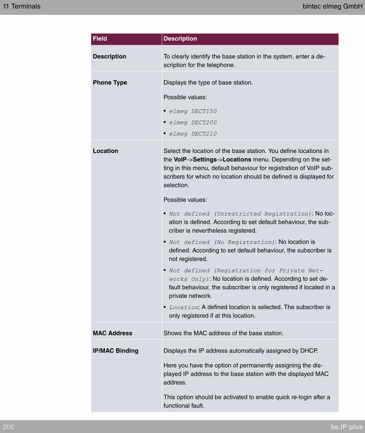
Field Description
Description To clearly identify the base station in the system, enter a de-
scription for the telephone.
Phone Type Displays the type of base station.
Possible values:
•
•
•
Location Select the location of the base station. You define locations in
the VoIP->Settings->Locations menu. Depending on the set-
ting in this menu, default behaviour for registration of VoIP sub-
scribers for which no location should be defined is displayed for
selection.
Possible values:
• : No loc-
ation is defined. According to set default behaviour, the sub-
criber is nevertheless registered.
• : No location is
defined. According to set default behaviour, the subscriber is
not registered.
•
: No location is defined. According to set de-
fault behaviour, the subscriber is only registered if located in a
private network.
• : A defined location is selected. The subscriber is
only registered if at this location.
MAC Address Shows the MAC address of the base station.
IP/MAC Binding Displays the IP address automatically assigned by DHCP.
Here you have the option of permanently assigning the dis-
played IP address to the base station with the displayed MAC
address.
This option should be activated to enable quick re-login after a
functional fault.
11 Terminals bintec elmeg GmbH
206 be.IP plus

The menu Advanced Settings consists of the following fields:
Fields in the menu Further Settings
Field Description
No Hold and Retrieve The performance features hold a call and retrieve a held call are
not available on certain telephones.
The function is activated by selecting .
The function is disabled by default.
Fields in the menu Codec Settings
Field Description
Codec Profile Select the Codec profile to be used. Codec profiles are con-
figured in the VoIP->Settings->Codec Profiles menu.
11.1.3.2 Numbers
In the menu Terminals->elmeg System Phones->elmeg DECT->Numbers you assign In-
ternal Numbers to the mobile parts. You can select from the numbers that you have cre-
ated for this purpose under Numbering->User Settings->Users.
The system automatically assigns a serial number, the Mobile Number, to each mobile
part so that you can identify the device. You can then use Add to assign a Internal Num-
ber to a mobile part from the list.
You can delete assigned numbers with .
Values in the list Numbers
Field Description
Mobile Number Displays the serial number of the mobile part. This number is
permanently assigned to the mobile part so that it can be
uniquely identified.
Internal Number Displays the assigned internal number.
Displayed Description Displays the description entered for the internal number. In
standby mode this description is shown on the mobile part's dis-
play.
User Displays the user's name.
bintec elmeg GmbH 11 Terminals
be.IP plus 207

11.1.3.3 Settings
In the Terminals->elmeg System Phones->elmeg DECT->Settings menu you can reset
the administrator password for the base station.
The menu consists of the following fields:
Fields in the menu Basic Settings
Field Description
Admin Password Select whether the administrator password should be reset.
The function is activated by selecting .
The function is disabled by default.
As soon as you select the OK button, the password is reset to
the default setting.
11.2 Other phones
In this menu, you perform assignment of configured internal numbers to the terminals and
set additional functions according to terminal type.
Terminals of the corresponding category (VoIP, ISDN, or analog) are sorted alphabetically
in the Description column. Click the column title of any other column to sort entries in as-
cending or descending order.
11.2.1 VoIP
In the Terminals->Other phones->VoIP menu, you configure the connected VoIP termin-
als. For example, you perform assignment of a configured internal number.
Specific instructions for configuring VoIP, see VoIP - Configuration example (a smartphone
as an internal VoIP telephone) on page 212.
11.2.1.1 Edit or New
Choose the icon to edit existing entries. Select the New button to add VoIP terminals.
The Terminals->Other phones->VoIP->New menu consists of the following fields:
Fields in the menu Basic Settings
11 Terminals bintec elmeg GmbH
208 be.IP plus

Field Description
Description Enter a description for the IP telephone.
Location Select the location of the telephone. You define locations in the
VoIP->Settings->Locations menu. Depending on the setting in
this menu, default behaviour for registration of VoIP subscribers
for which no location should be defined is displayed for selec-
tion.
Possible values:
• : No loc-
ation is defined. According to set default behaviour, the sub-
criber is nevertheless registered.
• : No location is
defined. According to set default behaviour, the subscriber is
not registered.
•
: No location is defined. According to set de-
fault behaviour, the subscriber is only registered if located in a
private network.
• : A defined location is selected. The subscriber
is only registered if at this location.
Fields in the menu Number Settings
Field Description
Internal Numbers Select the internal number for this terminal You can define sev-
eral internal numbers.
Possible values:
• : All configured internal
numbers are already in use. First configure another user with
additional numbers.
• : Select one of the existing numbers of
the configured users.
The menu Advanced Settings consists of the following fields:
Fields in the menu SIP Client Settings
bintec elmeg GmbH 11 Terminals
be.IP plus 209
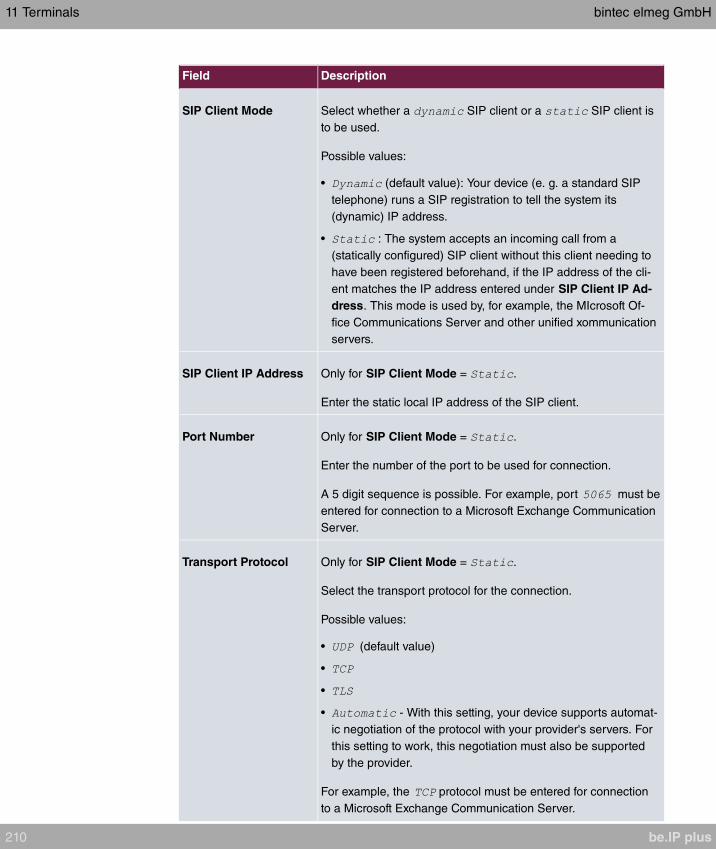
Field Description
SIP Client Mode Select whether a SIP client or a SIP client is
to be used.
Possible values:
• (default value): Your device (e. g. a standard SIP
telephone) runs a SIP registration to tell the system its
(dynamic) IP address.
• : The system accepts an incoming call from a
(statically configured) SIP client without this client needing to
have been registered beforehand, if the IP address of the cli-
ent matches the IP address entered under SIP Client IP Ad-
dress. This mode is used by, for example, the MIcrosoft Of-
fice Communications Server and other unified xommunication
servers.
SIP Client IP Address Only for SIP Client Mode = .
Enter the static local IP address of the SIP client.
Port Number Only for SIP Client Mode = .
Enter the number of the port to be used for connection.
A 5 digit sequence is possible. For example, port must be
entered for connection to a Microsoft Exchange Communication
Server.
Transport Protocol Only for SIP Client Mode = .
Select the transport protocol for the connection.
Possible values:
• (default value)
•
•
• - With this setting, your device supports automat-
ic negotiation of the protocol with your provider's servers. For
this setting to work, this negotiation must also be supported
by the provider.
For example, the protocol must be entered for connection
to a Microsoft Exchange Communication Server.
11 Terminals bintec elmeg GmbH
210 be.IP plus

Fields in the menu Codec Settings
Field Description
Codec Profile Select the codec profile to be used if the connection is over a
VoIP line. Codec profiles are configured in the VoIP->Settings-
>Codec Profiles menu.
Video Select if calls between IP telephones are to support the trans-
mission of video data. Video transmission can only be negoti-
ated between the participants if both support this feature.
SRTP Select if calls via this SIP provider may be secured with SRTP
(Secure Real-Time Transport Protocol).
Fields in the menu Further Settings
Field Description
Multiple SIP Connec-
tions (Sub-Exchange)
Select whether multilinks shall be allowed from this terminals.
Operation as subsystem: Only in case of connection of a sub-
system to a system Here, with a disabled performance feature,
only a connection via the subscriber SIP registration is possible.
If a second call comes in, it is accepted and the existing call is
held. With an enabled performance feature, several SIP con-
nections are possible over the same login. If the performance
feature is enabled for as system without subsystem, two simul-
taneous calls on the phone are not connected to each other
after the receiver is replaced but released, for example. Here,
the performance feature should not be set.
The function is activated by selecting .
The function is disabled by default.
No Hold and Retrieve The performance features "hold a call" and "retrieve a held call"
are not available on certain telephones.
The function is activated by selecting .
The function is disabled by default.
T.38 FAX support Select if you want to transmit FAX documents via Voice over IP
using the T.38 standard.
activates T.38 support.
Per default, the function is disabled.
bintec elmeg GmbH 11 Terminals
be.IP plus 211

Field Description
If the function is disabled, FAX documents are transmitted using
G.711.
11.2.2 VoIP - Configuration example (a smartphone as an in-
ternal VoIP telephone)
Requirements
• An be.IP
• A configured with the Assistents Initial operation SIP connection
• A taken with the Assistents in operation WLAN access point
• An Smartphone e.g. iPhone 4
• Available connection to the WLAN access poin the be.IP
• SIP app, Media5-fone, installed on the smartphone
Note
Please note that the scope of settings and supported functions may vary with different
versions of smartphone operating systems (iOS, Android) and the smartphone app,
Media5-fone.
Example scenario
11 Terminals bintec elmeg GmbH
212 be.IP plus

Configuration target
Integration of a smartphone as an internal VoIP phone
Overview of Configuration Steps
Creating a User and integrate Smartphone
Field Menu Value
Name N
e
Assistants->Telephony->Users->w
e.g.
Description N
e
Assistants->Telephony->Users->w
e.g.
Password N
e
Assistants->Telephony->Users->w
e.g.
Displayed Description N
e
Assistants->Telephony->Users->w-
>Add
e.g.
Internal Number N
e
Assistants->Telephony->Users->w-
>Add
e.g.
bintec elmeg GmbH 11 Terminals
be.IP plus 213

Field Menu Value
Description Terminals->Other
phones->VoIP->New
e.g.
Internal Numbers Terminals->Other
phones->VoIP->New
Configuration of the smartphone app using the example Media5-fone
Field Menu Value
Title New SIP Account -> Manual Set-
tings
e.g.
User Name New SIP Account -> Manual Set-
tings
e.g.
Password New SIP Account -> Manual Set-
tings
e.g.
Address New SIP Account -> Manual Set-
tings-> Server
e. g.
Port New SIP Account -> Manual Set-
tings-> Server
Activating a proxy New SIP Account -> Manual Set-
tings-> Server
SIP Transport New SIP Account -> Manual Set-
tings-> Server
Switch SRTP New SIP Account -> Manual Set-
tings-> Server
Mailbox Number New SIP Account -> Manual Set-
tings ->Advanced
e.g.
Write MWI New SIP Account -> Manual Set-
tings ->Advanced
DTMF Method New SIP Account -> Manual Set-
tings ->Advanced
Codecs Wi-Fi New SIP Account -> Manual Set-
tings ->Advanced
Configuration of external number
Field Menu Value
International Prefix /
Country Code
Assistants->Telephony->First
steps
e.g. /
National Prefix / City Assistants->Telephony->First e.g. /
11 Terminals bintec elmeg GmbH
214 be.IP plus

Field Menu Value
Code steps
Connection Type
bintec elmeg GmbH 11 Terminals
be.IP plus 215

Field Menu Value
New
Type
11 Terminals bintec elmeg GmbH
216 be.IP plus

Field Menu Value
New
Description e.g.
bintec elmeg GmbH 11 Terminals
be.IP plus 217
Field Menu Value
New->Next
Single Number (MSN) e.g.
11 Terminals bintec elmeg GmbH
218 be.IP plus

Field Menu Value
New->Next
Description e.g.
bintec elmeg GmbH 11 Terminals
be.IP plus 219

Field Menu Value
New->Next
Connection Type
11 Terminals bintec elmeg GmbH
220 be.IP plus

Field Menu Value
New
Type
bintec elmeg GmbH 11 Terminals
be.IP plus 221

Field Menu Value
New
Name e.g.
11 Terminals bintec elmeg GmbH
222 be.IP plus

Field Menu Value
New->Next
Single Number (MSN) e.g.
bintec elmeg GmbH 11 Terminals
be.IP plus 223
Field Menu Value
New->Next
Description e.g.
11 Terminals bintec elmeg GmbH
224 be.IP plus
Field Menu Value
New->Next
Connection Type
bintec elmeg GmbH 11 Terminals
be.IP plus 225

Field Menu Value
New
Type
11 Terminals bintec elmeg GmbH
226 be.IP plus

Field Menu Value
New
Name e.g.
bintec elmeg GmbH 11 Terminals
be.IP plus 227

Field Menu Value
New->Next
Single Number (MSN) e.g.
11 Terminals bintec elmeg GmbH
228 be.IP plus

Field Menu Value
New->Next
Description e.g.
bintec elmeg GmbH 11 Terminals
be.IP plus 229
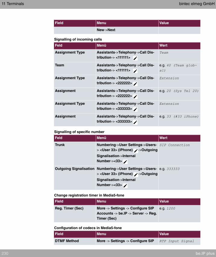
Field Menu Value
New->Next
Signalling of incoming calls
Feld Menü Wert
Assignment Type Assistants->Telephony->Call Dis-
tribution-> <111111>
Team Assistants->Telephony->Call Dis-
tribution-> <111111>
e.g.
Assignment Type Assistants->Telephony->Call Dis-
tribution-> <222222>
Assignment Assistants->Telephony->Call Dis-
tribution-> <222222>
e.g.
Assignment Type Assistants->Telephony->Call Dis-
tribution-> <333333>
Assignment Assistants->Telephony->Call Dis-
tribution-> <333333>
e.g.
Signalling of specific number
Feld Menü Wert
Trunk Numbering->User Settings->Users-
> <User 33> (iPhone) ->Outgoing
Signalisation->Internal
Number-><33>
Outgoing Signalisation Numbering->User Settings->Users-
> <User 33> (iPhone) ->Outgoing
Signalisation->Internal
Number-><33>
e.g.
Change registration timer in Media5-fone
Field Menu Value
Reg. Timer (Sec) More -> Settings -> Configure SIP
Accounts -> be.IP -> Server -> Reg.
Timer (Sec)
e.g.
Configuration of codecs in Media5-fone
Field Menu Value
DTMF Method More -> Settings -> Configure SIP
11 Terminals bintec elmeg GmbH
230 be.IP plus
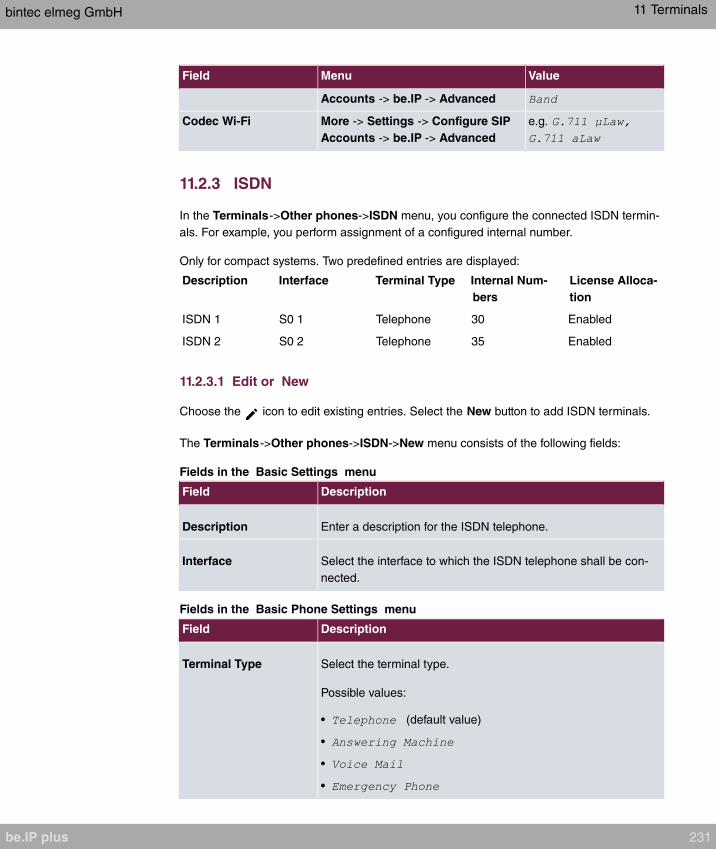
Field Menu Value
Accounts -> be.IP -> Advanced
Codec Wi-Fi More -> Settings -> Configure SIP
Accounts -> be.IP -> Advanced
e.g.
11.2.3 ISDN
In the Terminals->Other phones->ISDN menu, you configure the connected ISDN termin-
als. For example, you perform assignment of a configured internal number.
Only for compact systems. Two predefined entries are displayed:
Description Interface Terminal Type Internal Num-
bers
License Alloca-
tion
ISDN 1 S0 1 Telephone 30 Enabled
ISDN 2 S0 2 Telephone 35 Enabled
11.2.3.1 Edit or New
Choose the icon to edit existing entries. Select the New button to add ISDN terminals.
The Terminals->Other phones->ISDN->New menu consists of the following fields:
Fields in the Basic Settings menu
Field Description
Description Enter a description for the ISDN telephone.
Interface Select the interface to which the ISDN telephone shall be con-
nected.
Fields in the Basic Phone Settings menu
Field Description
Terminal Type Select the terminal type.
Possible values:
• (default value)
•
•
•
bintec elmeg GmbH 11 Terminals
be.IP plus 231
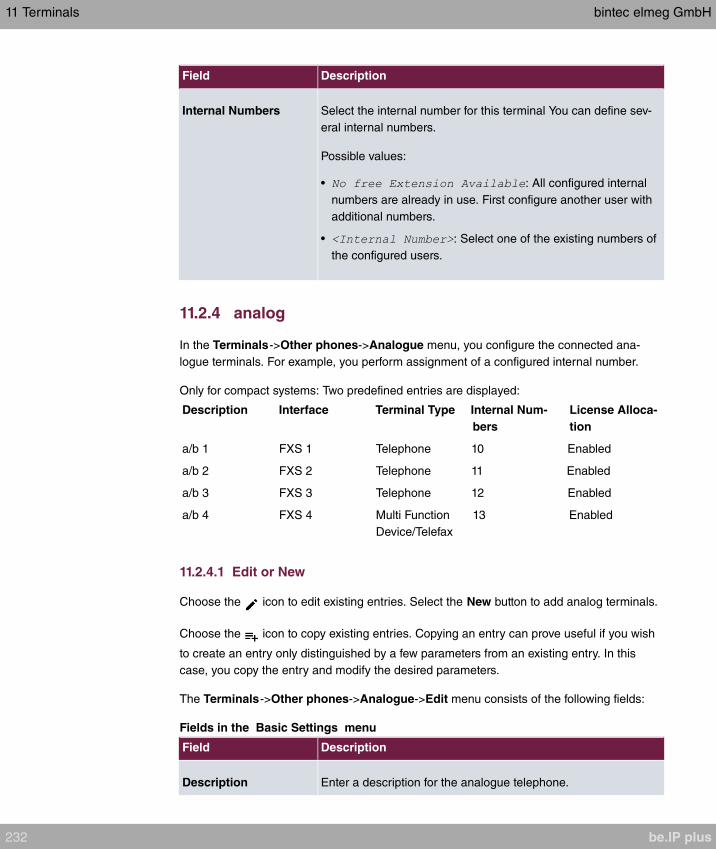
Field Description
Internal Numbers Select the internal number for this terminal You can define sev-
eral internal numbers.
Possible values:
• : All configured internal
numbers are already in use. First configure another user with
additional numbers.
• : Select one of the existing numbers of
the configured users.
11.2.4 analog
In the Terminals->Other phones->Analogue menu, you configure the connected ana-
logue terminals. For example, you perform assignment of a configured internal number.
Only for compact systems: Two predefined entries are displayed:
Description Interface Terminal Type Internal Num-
bers
License Alloca-
tion
a/b 1 FXS 1 Telephone 10 Enabled
a/b 2 FXS 2 Telephone 11 Enabled
a/b 3 FXS 3 Telephone 12 Enabled
a/b 4 FXS 4 Multi Function
Device/Telefax
13 Enabled
11.2.4.1 Edit or New
Choose the icon to edit existing entries. Select the New button to add analog terminals.
Choose the icon to copy existing entries. Copying an entry can prove useful if you wish
to create an entry only distinguished by a few parameters from an existing entry. In this
case, you copy the entry and modify the desired parameters.
The Terminals->Other phones->Analogue->Edit menu consists of the following fields:
Fields in the Basic Settings menu
Field Description
Description Enter a description for the analogue telephone.
11 Terminals bintec elmeg GmbH
232 be.IP plus
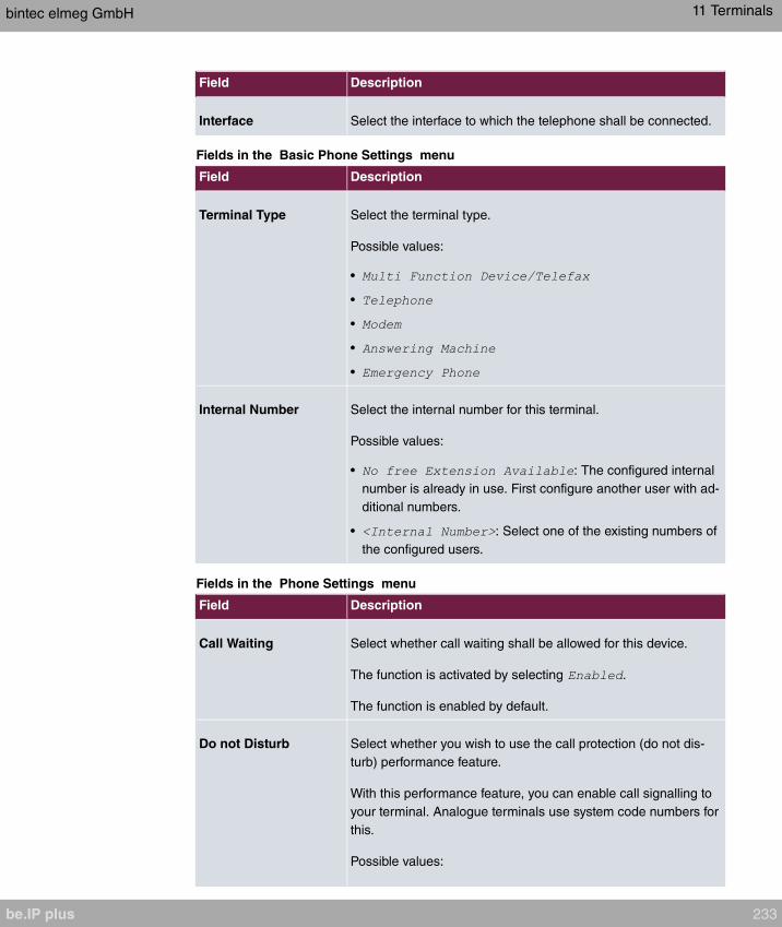
Field Description
Interface Select the interface to which the telephone shall be connected.
Fields in the Basic Phone Settings menu
Field Description
Terminal Type Select the terminal type.
Possible values:
•
•
•
•
•
Internal Number Select the internal number for this terminal.
Possible values:
• : The configured internal
number is already in use. First configure another user with ad-
ditional numbers.
• : Select one of the existing numbers of
the configured users.
Fields in the Phone Settings menu
Field Description
Call Waiting Select whether call waiting shall be allowed for this device.
The function is activated by selecting .
The function is enabled by default.
Do not Disturb Select whether you wish to use the call protection (do not dis-
turb) performance feature.
With this performance feature, you can enable call signalling to
your terminal. Analogue terminals use system code numbers for
this.
Possible values:
bintec elmeg GmbH 11 Terminals
be.IP plus 233

Field Description
•
•
•
The menu Advanced Settings consists of the following fields:
Fields in the CLIP Settings menu
Field Description
Show incoming Num-
ber (CLIP)
Select whether the subscriber's number shall be transmitted.
The function is activated by selecting .
The function is enabled by default.
Show Date and Time Only for Show incoming Number (CLIP)
Select whether the time and date should be taken from your
PABX system and displayed on the telephone.
The function is activated by selecting .
The function is enabled by default.
Show incoming Name
(CNIP)
Only for Show incoming Number (CLIP)
Select whether the caller's number shall be displayed. The
caller's number can be displayed if an entry exists in the system
telephone book.
The function is activated by selecting .
The function is enabled by default.
Show incoming wait-
ing Number (CLIP off
Hook)
Only for Show incoming Number (CLIP)
Select whether the number of a caller waiting during an existing
call shall be displayed.
The function is activated by selecting .
The function is enabled by default.
Fields in the Further Settings menu
11 Terminals bintec elmeg GmbH
234 be.IP plus

Field Description
Show new Messages
(MWI)
Only for Show incoming Number (CLIP)
Select whether new messages shall be signalled on a voice
mail system.
The function is activated by selecting .
The function is enabled by default.
Transmit Charges
Pulses
Select whether the system shall generate charge pulses for the
terminal from the ISDN network charge information. For this
purpose, you can define the charge impulse at 12 kHz or 16
kHz.
Possible values:
• : Charge information from the ISDN network is not trans-
mitted.
•
•
The default value is
FXS Ringing Fre-
quency
Call signalling in analogue terminals occurs by configuring a call
switching voltage at the called analogue connections. This call
switching voltage is converted into a specific ring tone by the
analogue terminal. In the system, for the analogue connections
you can set a call switching voltage with a frequency of
or .
The default value is Hz.
Flash Time for DTMF
Dialling
When operating analogue terminals with the multifrequency
code dialling method, you can set the flashtime that the system
detects as maximum flash length. If the terminal flash is longer
than the defined period, "replaced receiver" is detected.
Values from to are possible.
The default value is .
bintec elmeg GmbH 11 Terminals
be.IP plus 235

11.2.5 CAPI
If your device supports CAPI, you configure the connected CAPI terminals in the menu Ter-
minals->Other phones->CAPI. For example, you perform assignment of a configured in-
ternal number.
11.2.5.1 Edit or New
Choose the icon to edit existing entries. Select the New button to add CAPI terminals.
The Terminals->Other phones->CAPI->New menu consists of the following fields:
Fields in the menu Basic Settings
Field Description
Description Enter a description for the CAPI telephone.
Fields in the menu Basic Phone Settings
Field Description
Internal Numbers Use Add to select the internal number for this terminal. You can
define several internal numbers.
Possible values:
• : All configured internal
numbers are already in use. First configure another user with
additional numbers.
• : Select one of the existing numbers of
the configured users.
11.3 Overview
11.3.1 Overview
In the Terminals->Overview->Overview menu, you get an overview of all configured ter-
minals.
Values in the Overview list
11 Terminals bintec elmeg GmbH
236 be.IP plus
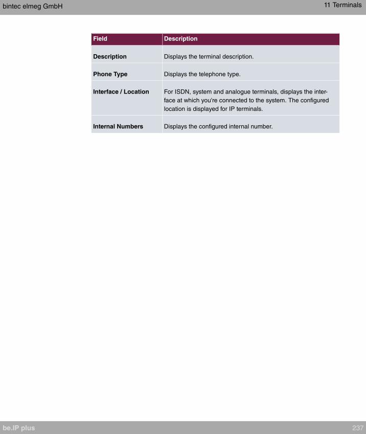
Field Description
Description Displays the terminal description.
Phone Type Displays the telephone type.
Interface / Location For ISDN, system and analogue terminals, displays the inter-
face at which you're connected to the system. The configured
location is displayed for IP terminals.
Internal Numbers Displays the configured internal number.
bintec elmeg GmbH 11 Terminals
be.IP plus 237
Chapter 12 Call Routing
The functions for external calls and automatic route selections for external calls are defined
in call routing.
12.1 Outgoing Services
In the Call Routing->Outgoing Services menu, you can configure the performance fea-
tures Direct Call, Call Forwarding, Dial Control and Priority Numbers.
12.1.1 Direct Call
In the Call Routing->Outgoing Services->Direct Call menu you configure numbers that
are dialled directly without the subscriber needing to dial a number themselves on the
phone.
You wish to configure a telephone for which a call to a specific number is set up even
without entry of the number (e.g. emergency telephone). You are not at home. However,
there is someone at home who needs to be able to reach you quickly and easily by tele-
phone, if required (e.g. children or grandparents). If you have set up the "Direct Call" func-
tion for one or more telephones, the receiver of the corresponding telephone only needs to
be lifted. After a period without further entries set in configuration, the system automatically
dials the configured direct call number.
If you do not dial within the specified period from picking up the receiver, automatic dialling
is initiated.
The time for Direct Call is set under System Management->Global Settings->Timer->Dir-
ect Call.
Note
In the system, up to 10 direct call destinations with names and telephone numbers can
be set up by the administrator. These destinations should then only be assigned to the
terminals by the user via the user configuration interface. In the configuration, system
direct call, or a direct call specifically configured for the terminal, can then be set by the
user.
12 Call Routing bintec elmeg GmbH
238 be.IP plus

12.1.1.1 Edit or New
Choose the icon to edit existing entries. Select the New button to create new entries.
The Call Routing->Outgoing Services->Direct Call->New menu consists of the following
fields:
Fields in the Basic Settings menu
Field Description
Description Enter a description for the entry.
Direct Call Number Enter the number to be automatically dialled if no number is to
be dialled for a certain time after the receiver has been picked
up.
12.1.2 Call Forwarding
In the Call Routing->Outgoing Services->Call Forwarding menu, you configure call for-
warding of external calls for an internal subscriber.
You are temporarily away from your office, but don't want to miss a call. With call forward-
ing to another number, e.g. your mobile, you can receive your calls even when you are not
at your desk. You can forward calls on your number to any call number. It can occur
, or . Call forwarding and can
exist concurrently. If you are not near your telephone, for example, the call is forwarded to
another number (e.g. your mobile phone) after a short period. If you are making a call at
your desk, other caller may receive the busy signal. You can forward these callers e.g. to a
colleague or the secretary by using call forwarding on busy.
Every internal subscriber to the system can forward her calls to another number. Calls can
be forwarded to internal subscriber numbers, internal team numbers or external numbers
When the number to which calls shall be forwarded is entered, the system automatically
checks whether it's an internal or external number.
In a team, call forwarding can be set up for one subscriber in the team. This call continues
to be signalled to the other team subscribers. Call forwarding to an internal or external sub-
scriber is performed in the system.
Call forwarding to an internal number is performed in the system. If an internal call to an ex-
ternal number is to be forwarded, forwarding also occurs in the system. Here, the connec-
tion is on the bundle cleared for the subscriber doing the setup. If call forwarding occurs via
an ISDN connection, one B channels remains in use; in case of forwarding from external to
external, it's both B channels. Two possibilities exist for call forwarding of an external call to
bintec elmeg GmbH 12 Call Routing
be.IP plus 239
an external number:
• Call forwarding in the exchange: Call forwarding is conducted at the exchange if only one
subscriber is entered in the call allocation for an external call. For call forwarding in the
exchange, the performance features Call Deflection (point-to-multipoint connection) or
Partial Rerouting (point-to-point connection) must be enabled with the network operator
for the relevant ISDN connections.
• Call forwarding in the system: Call forwarding occurs in the system if the required per-
formance features for call forwarding at the exchange are not available for the relevant
ISDN connections. If several telephones (e. g. a team), some of which have set up call
forwarding, receive an external call, the corresponding call forwarding is performed in the
system. Here, the external connection is set up over a bundle's B channel, cleared for the
subscriber initiating the setup. This B-channel remains assigned for the duration of active
call forwarding.
Note
If the system is connected to the external ISDN (if supported by you device), for ex-
ternal-to-external connections, the system systematically attempts to initiate call for-
warding via the exchange For teams, there can be manual definition of whether call
forwarding shall occur via the exchange or the system. If the system possesses no
ISDN connections, or if Call Deflection (point-to-multipoint connection) or Partial
Rerouting (point-to-point connection) has not been ordered from the network operator,
call forwarding occurs solely in the system.
12.1.2.1 Edit or New
Choose the icon to edit existing entries. Select the New button to create new entries.
The Call Routing->Outgoing Services->Call Forwarding->New menu consists of the fol-
lowing fields:
Fields in the Basic Settings menu
Field Description
Internal Number Select the internal number to which the incoming calls shall be
forwarded.
Type of Call Forward-
ing
Select when incoming calls shall be forwarded to the specified
internal number.
Possible values:
12 Call Routing bintec elmeg GmbH
240 be.IP plus
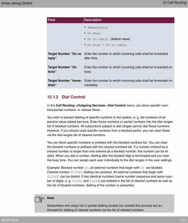
Field Description
•
•
• (default value)
•
Target Number "On no
reply"
Enter the number to which incoming calls shall be forwarded
after time.
Target Number "On
busy"
Enter the number to which incoming calls shall be forwarded on
busy.
Target Number "Imme-
diate"
Enter the number to which incoming calls shall be forwarded im-
mediately.
12.1.3 Dial Control
In the Call Routing->Outgoing Services->Dial Control menu, you block specific num-
bers/partial numbers, or release these .
You wish to prevent dialling of specific numbers in the system, e. g. the numbers of ex-
pensive value-added services. Enter these numbers or partial numbers into the dial ranges
list of blocked numbers. All subscribers subject to dial ranges cannot dial these numbers.
However, if you should need specific numbers from a blocked sector, you can clear these
via the dial ranges list of cleared numbers.
You can block specific numbers or prefixes with the blocked numbers list. You can clear
the blocked numbers or prefixes with the cleared numbers list. If a number entered as a
cleared number is longer than one entered as a blocked number, this number can be di-
alled. When you dial a number, dialling after the blocked digit is terminated and you hear
the busy tone. You can assign each user individually to the dial ranges in the user settings.
Example: Blocked number , all external numbers that begin with are blocked.
Cleared number , dialling can proceed. All external numbers that begin with
can be dialled. If two identical numbers (same number sequence and same num-
ber of digits, e. g. and ) are entered in the list of cleared numbers as well as
the list of blocked numbers, dialling of the number is prevented.
Note
Subscribers who enjoy full or partial dialling access (no outside line access) are au-
thorised for dialling of cleared numbers via the list of cleared numbers.
bintec elmeg GmbH 12 Call Routing
be.IP plus 241

Please ensure that the area code is entered in the configuration, otherwise, the block
can be circumvented in the local network by prefixing the area code.
12.1.3.1 Edit or New
Choose the icon to edit existing entries. Select the New button to create new entries.
The Call Routing->Outgoing Services->Dial Control->New menu consists of the follow-
ing fields:
Fields in the Basic Settings menu.
Field Description
Inhibited number Enter the number that cannot be dialled.
Enabled number Enter the number for which dialling is explicitly permitted.
12.1.4 Priority Numbers
In the Call Routing->Outgoing Services->Priority Numbers menu you configure num-
bers with particular special functions, e. g. emergency functions.
In your system configuration, you can enter numbers that must be accessible in an emer-
gency. If you now dial one of these priority numbers, it is detected by the system and an
ISDN B channel is automatically cleared. If the external ISDN B channels are already in
use, one of the ISDN B channels is freed up and the calling subscribers hear the busy tone.
An ongoing priority call is not interrupted.
12.1.4.1 Edit or New
Choose the icon to edit existing entries. Select the New button to create new entries.
The Call Routing->Outgoing Services->Priority Numbers->New menu consists of the
following fields:
Fields in the Basic Settings menu.
Field Description
Description Enter a description for the entry.
Priority Number Enter the number which can even be dialled if all B channels
are occupied. In this case, an external B channel is released for
12 Call Routing bintec elmeg GmbH
242 be.IP plus

Field Description
this connection and reassigned for the priority call. An ongoing
priority call is not interrupted.
12.1.5 Special Numbers
At a DDI connection, the called number of an outgoing call is automatically converted to the
international E.164 format. This conversion is undesirable for certain numbers. Exceptions
from the conversion can be configured here.
12.1.5.1 Edit or New
Choose the icon to edit existing entries. Select the New button to create new entries.
The Call Routing->Outgoing Services->Special Numbers->New menu consists of the
following fields:
Fields in the Basic Settings menu
Field Description
Description Enter a description for the entry.
Special Number Specify the number that is to be excepted from E.164 conver-
sion.
12.2 Automatic Route Selection
In the Call Routing->Automatic Route Selection menu, you can set up routes for extern-
al calls in addition to configured line occupancy. Here, bundles released for users can be
selectively assigned to ongoing calls according to the dialled number, or new providers
entered along with their network access prefixes. You then specifically define the routing
for individually created zones for every weekday.
12.2.1 General
In the Call Routing->Automatic Route Selection->General menu, you enable the ARS -
Automatic Route Selection - function and select the desired route level.
The menu consists of the following fields:
Fields in the Basic Settings menu.
bintec elmeg GmbH 12 Call Routing
be.IP plus 243
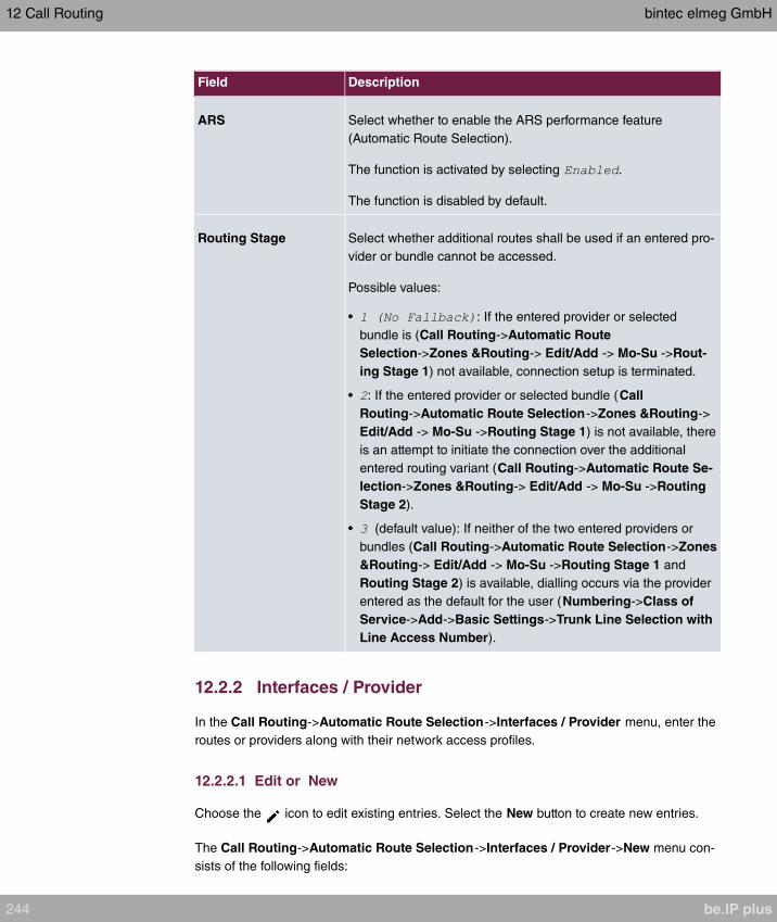
Field Description
ARS Select whether to enable the ARS performance feature
(Automatic Route Selection).
The function is activated by selecting .
The function is disabled by default.
Routing Stage Select whether additional routes shall be used if an entered pro-
vider or bundle cannot be accessed.
Possible values:
• : If the entered provider or selected
bundle is (Call Routing->Automatic Route
Selection->Zones &Routing-> Edit/Add -> Mo-Su ->Rout-
ing Stage 1) not available, connection setup is terminated.
• : If the entered provider or selected bundle (Call
Routing->Automatic Route Selection->Zones &Routing->
Edit/Add -> Mo-Su ->Routing Stage 1) is not available, there
is an attempt to initiate the connection over the additional
entered routing variant (Call Routing->Automatic Route Se-
lection->Zones &Routing-> Edit/Add -> Mo-Su ->Routing
Stage 2).
• (default value): If neither of the two entered providers or
bundles (Call Routing->Automatic Route Selection->Zones
&Routing-> Edit/Add -> Mo-Su ->Routing Stage 1 and
Routing Stage 2) is available, dialling occurs via the provider
entered as the default for the user (Numbering->Class of
Service->Add->Basic Settings->Trunk Line Selection with
Line Access Number).
12.2.2 Interfaces / Provider
In the Call Routing->Automatic Route Selection->Interfaces / Provider menu, enter the
routes or providers along with their network access profiles.
12.2.2.1 Edit or New
Choose the icon to edit existing entries. Select the New button to create new entries.
The Call Routing->Automatic Route Selection->Interfaces / Provider->New menu con-
sists of the following fields:
12 Call Routing bintec elmeg GmbH
244 be.IP plus
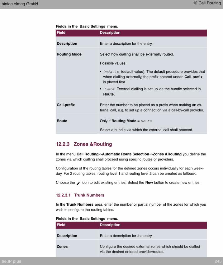
Fields in the Basic Settings menu.
Field Description
Description Enter a description for the entry.
Routing Mode Select how dialling shall be externally routed.
Possible values:
• (default value): The default procedure provides that
when dialling externally, the prefix entered under Call-prefix
is placed first.
• : External dialling is set up via the bundle selected in
Route.
Call-prefix Enter the number to be placed as a prefix when making an ex-
ternal call, e.g. to set up a connection via a call-by-call provider.
Route Only if Routing Mode =
Select a bundle via which the external call shall proceed.
12.2.3 Zones &Routing
In the menu Call Routing->Automatic Route Selection->Zones &Routing you define the
zones via which dialling shall proceed using specific routes or providers.
Configuration of the routing tables for the defined zones occurs individually for each week-
day. For 2 routing tables, routing level 1 and routing level 2 can be created as fallback.
Choose the icon to edit existing entries. Select the New button to create new entries.
12.2.3.1 Trunk Numbers
In the Trunk Numbers area, enter the number or partial number of the zones for which you
wish to configure the routing tables.
Fields in the Basic Settings menu.
Field Description
Description Enter a description for the entry.
Zones Configure the desired external zones which should be dialled
via the desired entered provider/routes.
bintec elmeg GmbH 12 Call Routing
be.IP plus 245

Field Description
Possible values:
• : Enter the number or part of a
number identifying a zone.
• : Enter a name for this zone.
12.2.3.2 Mon - Sun
In the Mon - Sun area, select the desired times for each routing level, and the desired
route or provider via which outgoing calls shall be routed from the entered time.
Fields in the <Weekday> menu
Field Description
Routing Stage 1 Configure the switching times for routing level 1. For this, first
select the Start Time from which routing shall occur over a spe-
cific interface or a specific network provider, and select the latter
under Interface / Provider.
Routing Stage 2 Configure the switching times for routing level 2. For this, first
select the Start Time from which routing shall occur over a spe-
cific interface or a specific network provider, and select the latter
under Interface / Provider.
12 Call Routing bintec elmeg GmbH
246 be.IP plus
Chapter 13 Applications
Internal telephone performance features of the system are set up under Applications.
13.1 Calendar
In the Applications->Calendar menu, you can decide whether to make new entries or
modifications in the calendar.
Every company has fixed business hours. You can enter these in the system's internal cal-
endar. For example, all calls outside of business hours can be signalled to a exchange or
an answering machine. During this period, your employees can perform other tasks,
without being interrupted by telephone calls. The individual call options of a team are auto-
matically switched through the calendars.
You wish to modify the external calling authorisations after business hours for specific sub-
scribers. In the system configuration, you can set individually for each user whether the au-
thorisation for external calls is automatically switched. The switch occurs according to the
data in the assigned calendar.
You can set up five types of calendars in the system. The "Authorisation Class" and "Night
Operation" calendars are intended for central switching and can only be set up once. The
"Team Signalling", "Intercom Signalling" and "Redirect to internal/external number" calen-
dars can be set up repeatedly. Several different switching times can be selected for each
weekday.
In the configuration, a calendar can be assigned to all performance features for which sev-
eral options can be defined (e.g. teams) Switching between the individual call options then
occurs at the switching times of the assigned calendar.
13.1.1 Calendar
In the menu Applications->Calendar->Calendar you can view, modify or copy a previ-
ously set calendar as well as create new calendars.
Choose the icon to edit existing entries. Select the New button to create new entries.
13.1.1.1 General
In the General area you define the name of the calendar to be created.
The menu Applications->Calendar->Calendar->General consists of the following fields:
bintec elmeg GmbH 13 Applications
be.IP plus 247
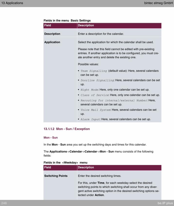
Fields in the menu Basic Settings
Field Description
Description Enter a description for the calendar.
Application Select the application for which the calendar shall be used.
Please note that this field cannot be edited with pre-existing
entries. If another application is to be configured, you must cre-
ate another entry and delete the existing one.
Possible values:
• (default value): Here, several calendars
can be set up.
• : Here, several calendars can be set
up.
• : Here, only one calendar can be set up.
• : Here, only one calendar can be set up.
• : Here,
several calendars can be set up.
• : Here, several calendars can be set
up.
• : Here, several calendars can be set up.
13.1.1.2 Mon - Sun / Exception
Mon - Sun
In the Mon - Sun area you set up the switching days and times for this calendar.
The Applications->Calendar->Calendar->Mon - Sun menu consists of the following
fields:
Fields in the <Weekday> menu
Field Description
Switching Points Enter the desired switching times.
For this, under Time, for each weekday select the desired
switching points to which switching shall occur from any diver-
gent active switching option in the desired switching options se-
lected under Action.
13 Applications bintec elmeg GmbH
248 be.IP plus
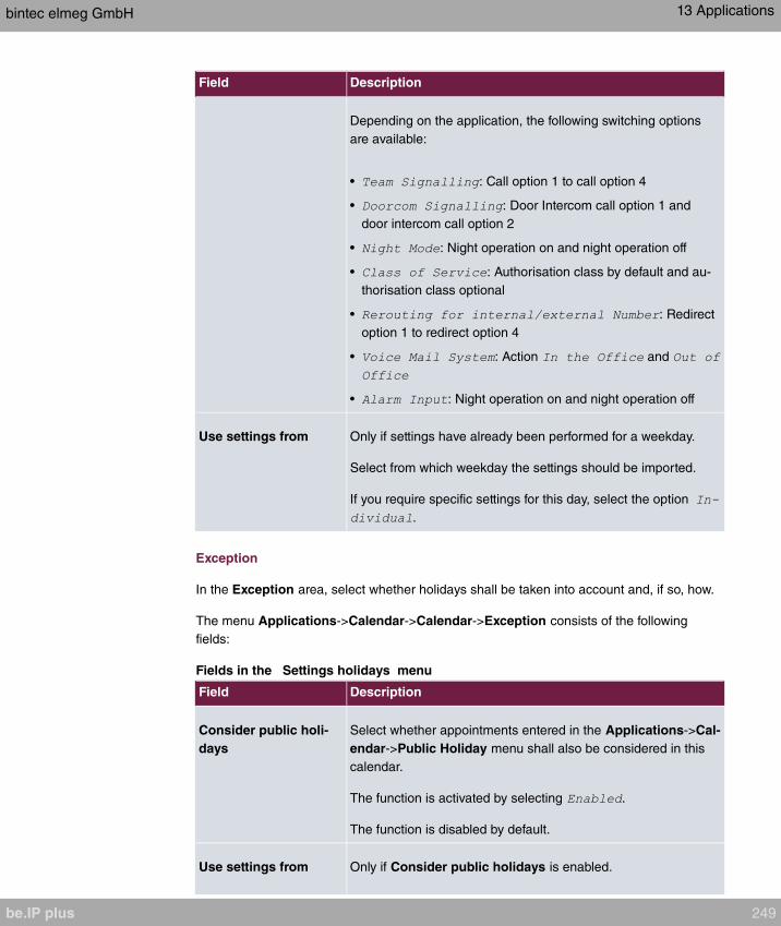
Field Description
Depending on the application, the following switching options
are available:
• : Call option 1 to call option 4
• : Door Intercom call option 1 and
door intercom call option 2
• : Night operation on and night operation off
• : Authorisation class by default and au-
thorisation class optional
• : Redirect
option 1 to redirect option 4
• : Action and
• : Night operation on and night operation off
Use settings from Only if settings have already been performed for a weekday.
Select from which weekday the settings should be imported.
If you require specific settings for this day, select the option
.
Exception
In the Exception area, select whether holidays shall be taken into account and, if so, how.
The menu Applications->Calendar->Calendar->Exception consists of the following
fields:
Fields in the Settings holidays menu
Field Description
Consider public holi-
days
Select whether appointments entered in the Applications->Cal-
endar->Public Holiday menu shall also be considered in this
calendar.
The function is activated by selecting .
The function is disabled by default.
Use settings from Only if Consider public holidays is enabled.
bintec elmeg GmbH 13 Applications
be.IP plus 249
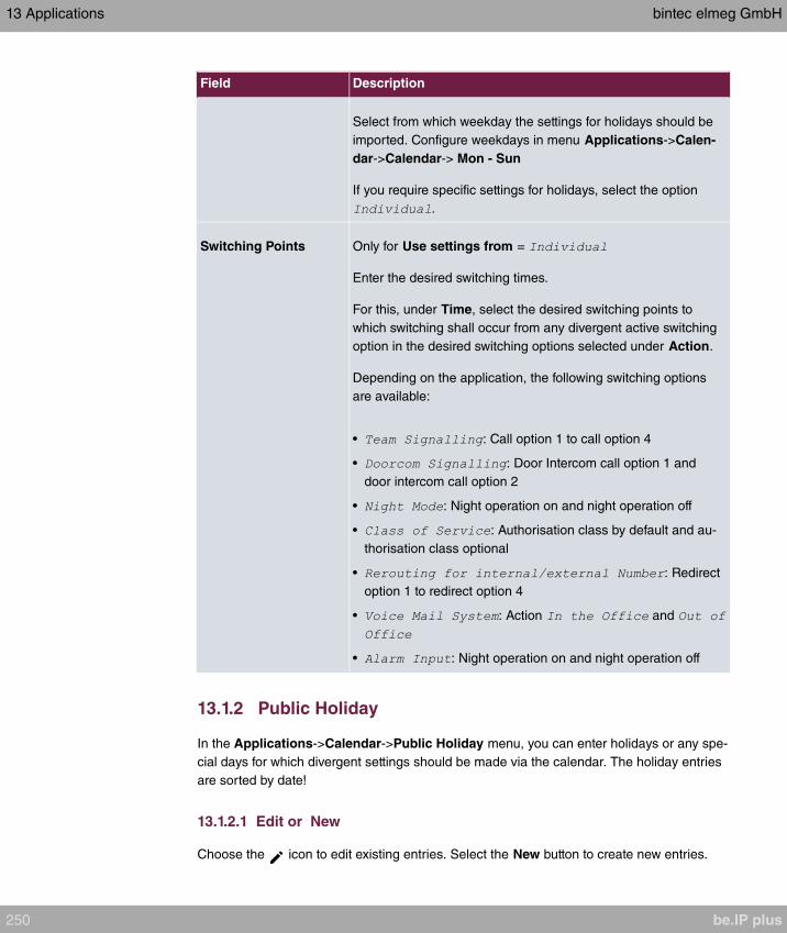
Field Description
Select from which weekday the settings for holidays should be
imported. Configure weekdays in menu Applications->Calen-
dar->Calendar-> Mon - Sun
If you require specific settings for holidays, select the option
.
Switching Points Only for Use settings from =
Enter the desired switching times.
For this, under Time, select the desired switching points to
which switching shall occur from any divergent active switching
option in the desired switching options selected under Action.
Depending on the application, the following switching options
are available:
• : Call option 1 to call option 4
• : Door Intercom call option 1 and
door intercom call option 2
• : Night operation on and night operation off
• : Authorisation class by default and au-
thorisation class optional
• : Redirect
option 1 to redirect option 4
• : Action and
• : Night operation on and night operation off
13.1.2 Public Holiday
In the Applications->Calendar->Public Holiday menu, you can enter holidays or any spe-
cial days for which divergent settings should be made via the calendar. The holiday entries
are sorted by date!
13.1.2.1 Edit or New
Choose the icon to edit existing entries. Select the New button to create new entries.
13 Applications bintec elmeg GmbH
250 be.IP plus

The menu Applications->Calendar->Public Holiday->New consists of the following
fields:
Fields in the Basic Settings menu.
Field Description
Description Enter a description for a holiday.
Date (DD - MM) Enter the date with day and month in two-digit form. Incorrect
entries, e. g. 31.02 are accepted and saved but not executed by
the system.
13.2 Rerouting
In the Applications->Rerouting menu, you configure how incoming calls should be
handled by default in the system.
13.2.1 Rerouting Functions
In the Applications->Rerouting->Rerouting Functions menu you can set up various re-
direct options for , , or
. You then assign these redirect options to the external connections in the Number-
ing->Call Distribution->Incoming Distribution menu.
13.2.1.1 Edit or New
Choose the icon to edit existing entries. Select the New button to create new redirect
options.
The Applications->Rerouting->Rerouting Functions->New menu consists of the follow-
ing fields:
Fields in the Basic Settings menu.
Field Description
Description Enter a description for the redirect function.
Type of Rerouting
Function
Select the desired exchange function.
Possible values:
• (default value)
•
bintec elmeg GmbH 13 Applications
be.IP plus 251
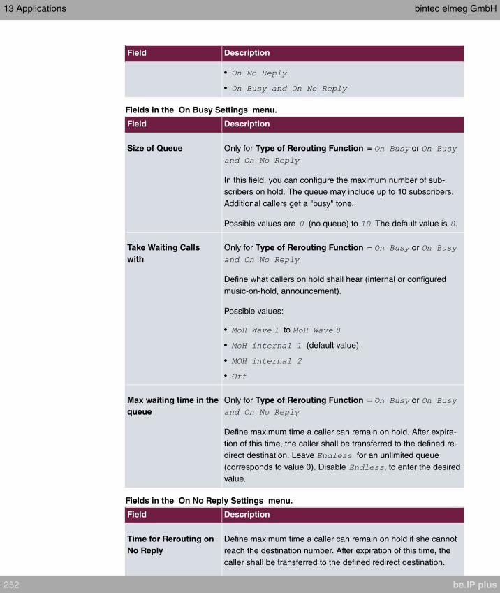
Field Description
•
•
Fields in the On Busy Settings menu.
Field Description
Size of Queue Only for Type of Rerouting Function = or
In this field, you can configure the maximum number of sub-
scribers on hold. The queue may include up to 10 subscribers.
Additional callers get a "busy" tone.
Possible values are (no queue) to . The default value is .
Take Waiting Calls
with
Only for Type of Rerouting Function = or
Define what callers on hold shall hear (internal or configured
music-on-hold, announcement).
Possible values:
• to
• (default value)
•
•
Max waiting time in the
queue
Only for Type of Rerouting Function = or
Define maximum time a caller can remain on hold. After expira-
tion of this time, the caller shall be transferred to the defined re-
direct destination. Leave for an unlimited queue
(corresponds to value 0). Disable , to enter the desired
value.
Fields in the On No Reply Settings menu.
Field Description
Time for Rerouting on
No Reply
Define maximum time a caller can remain on hold if she cannot
reach the destination number. After expiration of this time, the
caller shall be transferred to the defined redirect destination.
13 Applications bintec elmeg GmbH
252 be.IP plus
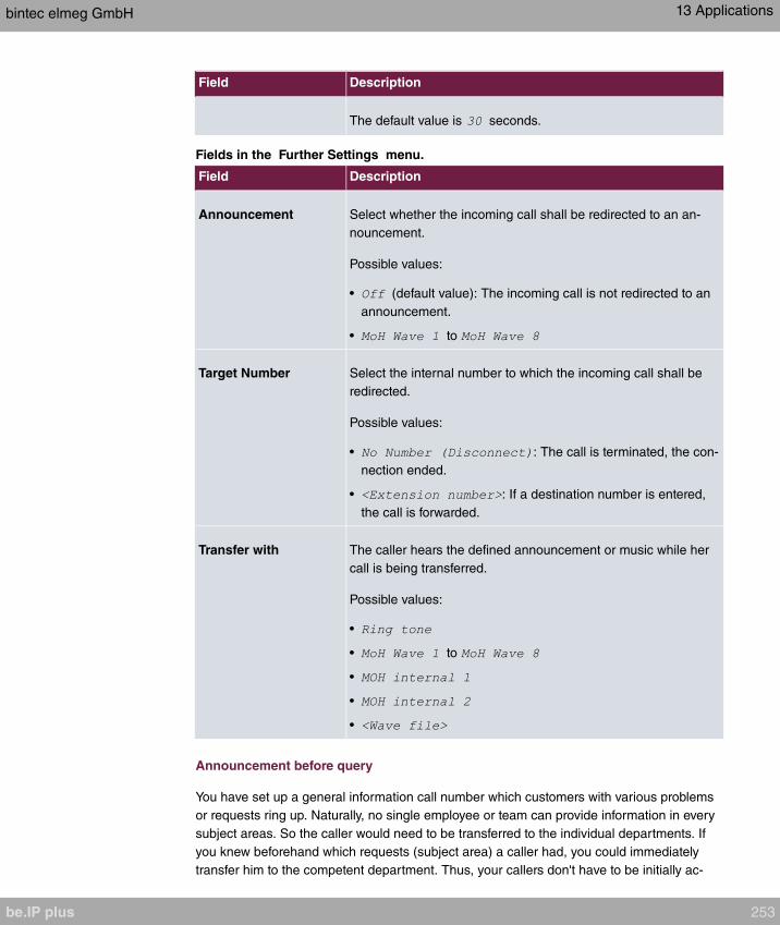
Field Description
The default value is seconds.
Fields in the Further Settings menu.
Field Description
Announcement Select whether the incoming call shall be redirected to an an-
nouncement.
Possible values:
• (default value): The incoming call is not redirected to an
announcement.
• to
Target Number Select the internal number to which the incoming call shall be
redirected.
Possible values:
• : The call is terminated, the con-
nection ended.
• : If a destination number is entered,
the call is forwarded.
Transfer with The caller hears the defined announcement or music while her
call is being transferred.
Possible values:
•
• to
•
•
•
Announcement before query
You have set up a general information call number which customers with various problems
or requests ring up. Naturally, no single employee or team can provide information in every
subject areas. So the caller would need to be transferred to the individual departments. If
you knew beforehand which requests (subject area) a caller had, you could immediately
transfer him to the competent department. Thus, your callers don't have to be initially ac-
bintec elmeg GmbH 13 Applications
be.IP plus 253

cepted and transferred by an exchange. Every caller decides for him/herself with which em-
ployee he/she wishes to be connected.
With the performance feature Auto Attendant with DISA calls are automatically accepted
by the system. The caller then hears an announcement with information about which
entries are possible during or after the announcement. Once the entry is made, the an-
nouncement ends and the caller is transferred to an internal subscriber or team. If the caller
provides a false or no entry, he/she is transferred to the defined redirect destination
(internal subscriber or team). While being transferred, the caller hears a ring tone or the
system's music-on-hold.
Note
DISA - Direct Inward System Access Once a call is received by the system, the caller
is automatically transferred after a code number is entered. This code is assigned to
an internal number in the system. Entry of a number or code must occur during the an-
nouncement. Once the announcement (Wave file) ends, no more entries are accepted.
There follows redirect to a defined redirect destination. The performance feature Auto
Attendant with DISA is an integral part of the system and can accept up to 28 calls
simultaneously.
Fields in the Announcement/Auto Attendant Settings menu.
Field Description
Call Switching Select how incoming calls are to be transferred.
Possible values:
• (default value): The con-
figured announcement is played. There follows either transfer
to the configured internal number, or the connection is inter-
rupted and the caller hears the busy tone.
• : The caller is prompted
to enter an internal number. The call is forwarded to the num-
ber.
• : The caller is prompted to
enter a code number from 0 to 9. The desired internal num-
bers are assigned to the codes. The caller is then transferred
to the configured internal number.
Number of playbacks Select how many times the announcement shall be continuously
repeated. At conclusion, the caller hears the busy tone.
13 Applications bintec elmeg GmbH
254 be.IP plus

Field Description
Auto Attendant with
DISA
Only if Call Switching =
For ever desired DISA code number, select the desired internal
number to which the caller shall be transferred.
13.2.2 Rerouting Applications
In the Applications->Rerouting->Rerouting Applications menu, you can configure when
which redirect option is to be enabled. You can switch the various options either via calen-
dar or manually.
Choose the icon to edit existing entries. Select the New button to create new redirect
applications.
13.2.2.1 General
In the General area, you perform basic settings for a redirect application.
The Applications->Rerouting->Rerouting Applications->New menu consists of the fol-
lowing fields:
Fields in the Basic Settings menu.
Field Description
Description Enter a description for the redirect application.
Type of Rerouting Ap-
plication
Select the destination to which an incoming call shall be redirec-
ted.
Possible values:
• (default value)
•
•
Switch call signalling Select how to switch between options
Possible values:
•
•
bintec elmeg GmbH 13 Applications
be.IP plus 255

13.2.2.2 Variant 1 - 4
In the Variant area, you configure the redirect options. You can define up to 4 options.
The menu Applications->Rerouting->Rerouting Applications->Variant consists of the
following fields:
Fields in the Basic Settings menu.
Field Description
Assignment Choose the redirect function to which you wish to assign the se-
lected option.
13.3 Voice Applications
In the Applications->Voice Applications menu, you configure you system's wave files.
A professional greeting, especially on the telephone, constitutes a company's visiting card.
Voice applications make this possible for every business. Indeed, while being transferred,
the caller receives information that's individually tailored, e. g. according to department, or
is simply entertained with pleasant music-on-hold.
You wish to employ special music as music-on-hold, or specific announcements for your
clients. You can load your self-produced Wave files to the system.
User-specific voice and music files can be saved in the system. Storage space for 2 MoH
melodies is available in the system basic settings. The available storage space can be ex-
tended with an SD card (if supported by you device). The length of the language and music
files that can be saved is based upon the SD card used. Voice and music data is saved in
Wave format.
The following voice applications can be defined in the system:
• Announcement before query
• Announcement without query/Infobox
• Wake-up call
• Music on hold
You can find additional information on function, configuration and operation in the descrip-
tion of the individual performance features.
Basic settings of voice applications
13 Applications bintec elmeg GmbH
256 be.IP plus

The voice applications can be assigned to individual performance features in two different
ways.
Every user employing a voice application with this connection always hears the corres-
ponding voice announcement or music from the start. A newly-arrived user hears the voice
announcement or music from the start. The number of users who can simultaneously use
such a voice application is limited to 28.
Please note that externally played music or voice application music are free of third-party
copyrights (GEMA free). Files in other formats must be converted into the company-specific
Wave format before being saved in the system.
Note
Please note that Wave files must be available in the following format:
• Bit rate: 128 kbps
• Sampling size: 16 bits
• Channels 1 (mono)
• Sampling rate: 8 kHz
• Audio format: PCM
13.3.1 Wave Files
In the Applications->Voice Applications->Wave Files menu, you can configure your an-
nouncement/melody files and volume. You also have the option to play back voicemail
messages or download these to your PC. To save a message, click on the icon. The
download dialog then opens. To listen to a message, click on the icon.
13.3.1.1 Edit
Choose the icon to edit existing entries. Select to change the entry.
and are files specified in the system and can thus
not be deleted.
The Applications->Voice Applications->Wave Files->Edit menu consists of the following
fields:
Fields in the Basic Settings menu.
bintec elmeg GmbH 13 Applications
be.IP plus 257
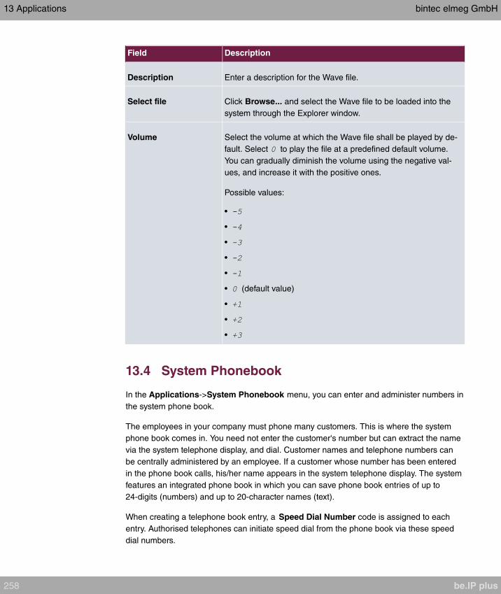
Field Description
Description Enter a description for the Wave file.
Select file Click Browse... and select the Wave file to be loaded into the
system through the Explorer window.
Volume Select the volume at which the Wave file shall be played by de-
fault. Select to play the file at a predefined default volume.
You can gradually diminish the volume using the negative val-
ues, and increase it with the positive ones.
Possible values:
•
•
•
•
•
• (default value)
•
•
•
13.4 System Phonebook
In the Applications->System Phonebook menu, you can enter and administer numbers in
the system phone book.
The employees in your company must phone many customers. This is where the system
phone book comes in. You need not enter the customer's number but can extract the name
via the system telephone display, and dial. Customer names and telephone numbers can
be centrally administered by an employee. If a customer whose number has been entered
in the phone book calls, his/her name appears in the system telephone display. The system
features an integrated phone book in which you can save phone book entries of up to
24-digits (numbers) and up to 20-character names (text).
When creating a telephone book entry, a Speed Dial Number code is assigned to each
entry. Authorised telephones can initiate speed dial from the phone book via these speed
dial numbers.
13 Applications bintec elmeg GmbH
258 be.IP plus
System telephones
System telephones can dial from the system phone book via a special menu. To search for
a telephone entry, enter the first letters (max. 8) of the desired name and confirm the entry.
The system always provides 8 phone book entries, which you can view successively. Se-
lect the desired entry and confirm with OK. You must now begin to dial within 5 seconds.
The system telephone redialling list displays the name of the dialled subscriber instead of
her number. If a system telephone receives a call whose number and name are saved in
the system phone book, the caller's name is indicated in the system telephone display.
Note
The user's other numbers (Mobile Number and Home Number) are only displayed in
the system telephone phone book menu. They are not displayed in the System
Phonebook menu of the user interface. Entries in the system telephone phone book
menu with the (M) mark refer to an entered Mobile Number of a user; those with the
(H) mark to Home Number.
Note
Your PABX system supports LDAP (Lightweight Directory Access Protocol) for provid-
ing the entries of the system phonebook to other devices. Name, Number as well as
mobile and private numbers can be transferred this way.
13.4.1 Entries
In the Applications->System Phonebook->Entries menu, all configured telephone book
entries are displayed with the corresponding speeddial index. The entries in the Descrip-
tion column are sorted alphabetically. Click the column title of any column to sort entries in
ascending or descending order.
13.4.1.1 Edit or New
Choose the icon to edit existing entries. Select the New button to create new entries.
The menu Applications->System Phonebook->Entries->New consists of the following
fields:
Fields in the Phonebook Entry menu.
bintec elmeg GmbH 13 Applications
be.IP plus 259

Field Description
Description Enter a description for the entry. Subsequent sorting in the
phone book follows the initial letters of the entry.
Phone Number Enter the telephone number (internal or external).
Speed Dial Number Enter a speed dial code. If a speed dial code is entered, count-
ing is automatic; i.e. speed dial is automatically assigned.
Numbers from to are possible.
Call Through Select whether the telephone number for the Call Through
function has been activated. If a telephone number is approved
for this, and the caller uses this number for the Call Through
functions, the caller's authorisation to use the function is
checked against the phonebook record.
The function is activated by selecting .
The function is disabled by default.
13.4.2 Import / Export
You can import and export phone book data in the Applications->System
Phonebook->Import / Export menu. You can import data exported from Microsoft Out-
look, for example. The phone book data stored in your device is exported to a text file.
The menu consists of the following fields:
Fields in the Basic Settings menu.
Field Description
Action Select the desired action.
Possible values:
• (default value): You can export the names saved in
Applications->System Phonebook->Entries into a text file
(specifying phone number, speed dial, call through).
• : You can import a text file in the following format: The
file imported must consist of individual rows in the following
format: name, phone number, speed dial, call through (1 = en-
abled, 2 = disabled).
13 Applications bintec elmeg GmbH
260 be.IP plus

Field Description
Example:
Name,Phone Number,Speeddial Number,Call Through
Hans,123456,1,1
Klaus,234567,2,2
Max,345678,3,1
Separator Only for Action = and Default File Format not enabled
Enter the separator type in the import file.
Possible values:
• (default value)
•
•
•
Select file Only for Action = select the file to be imported.
You also have the option to import a CSV file.
Example of a CSV file which can be imported
If the data record consists of more than one column, you have the option to generate two
address book entries from the data record for the import (e.g. one for business and one
private entry.) To do this, specify the data to be used as the name and phone number in an
additional import step. If you want to generate only one phonebook entry, select the blank
option in all selection fields for the second record Phonebook Import.
Fields in the Phonebook Import menu.
Field Description
Phone Number Select which data is to be used from a data record as the
phonenumber.
Name Select which columns are to be used from a data record as the
bintec elmeg GmbH 13 Applications
be.IP plus 261
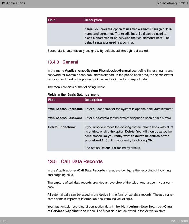
Field Description
name. You have the option to use two elements here (e.g. fore-
name and surname). The middle input field can be used to
place a character string between the two elements here. The
default separator used is a comma.
Speed dial is automatically assigned. By default, call through is disabled.
13.4.3 General
In the menu Applications->System Phonebook->General you define the user name and
password for system phone book administration. In the phone book area, the administrator
can view and modify the phone book, as well as import and export data.
The menu consists of the following fields:
Fields in the Basic Settings menu.
Field Description
Web Access Username Enter a user name for the system telephone book administrator.
Web Access Password Enter a password for the system telephone book administrator.
Delete Phonebook If you wish to remove the existing system phone book with all of
its entries, enable the option Delete. You will then be asked for
confirmation Do you really want to delete all entries of the
phonebook?. Confirm your entry by clicking OK.
The option Delete is disabled by default.
13.5 Call Data Records
In the Applications->Call Data Records menu, you configure the recording of incoming
and outgoing calls.
The capture of call data records provides an overview of the telephone usage in your com-
pany.
All external calls can be saved in the device in the form of call data records. These data re-
cords contain important information about the individual calls.
You must enable recording of connection data in the Numbering->User Settings->Class
of Services->Applications menu. The function is not activated in the ex works state.
13 Applications bintec elmeg GmbH
262 be.IP plus
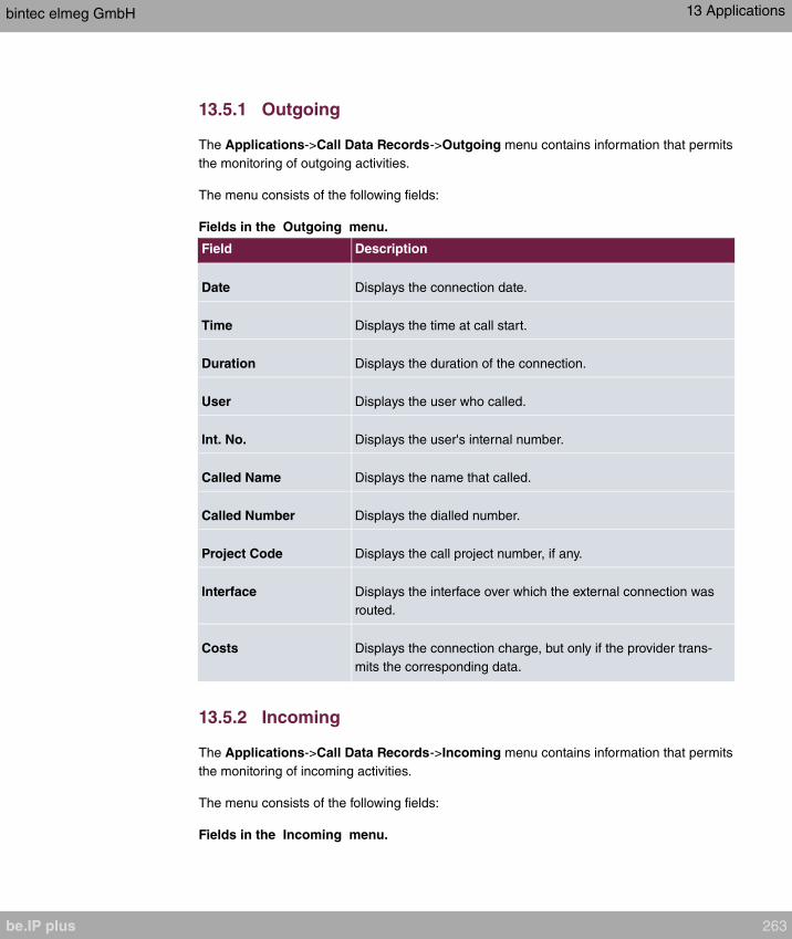
13.5.1 Outgoing
The Applications->Call Data Records->Outgoing menu contains information that permits
the monitoring of outgoing activities.
The menu consists of the following fields:
Fields in the Outgoing menu.
Field Description
Date Displays the connection date.
Time Displays the time at call start.
Duration Displays the duration of the connection.
User Displays the user who called.
Int. No. Displays the user's internal number.
Called Name Displays the name that called.
Called Number Displays the dialled number.
Project Code Displays the call project number, if any.
Interface Displays the interface over which the external connection was
routed.
Costs Displays the connection charge, but only if the provider trans-
mits the corresponding data.
13.5.2 Incoming
The Applications->Call Data Records->Incoming menu contains information that permits
the monitoring of incoming activities.
The menu consists of the following fields:
Fields in the Incoming menu.
bintec elmeg GmbH 13 Applications
be.IP plus 263

Field Description
Date Displays the connection date.
Time Displays the time at call start.
Duration Displays the duration of the connection.
User Displays the user who was called.
Int. No. Displays the user's internal number.
Caller Name Displays the name of the caller.
External Number Displays the caller's number.
Project Code Displays the call project number, if any.
Interface Displays the interface over which the connection from outside
was routed.
13.5.3 General
In the Applications->Call Data Records->General menu, you can define how connection
data are saved in the system.
The menu consists of the following fields:
Fields in the Basic Settings menu.
Field Description
Web Access Username Enter a user name for the call data administrator.
Web Access Password Enter a password for the call data administrator.
Save outgoing calls Select which outgoing connections should be saved.
Possible values:
• (default value)
•
•
13 Applications bintec elmeg GmbH
264 be.IP plus

Field Description
Save incoming calls Select which incoming connections should be saved.
Possible values:
• (default value)
•
•
Privacy Number Trun-
cation
Select whether to save the number in abbreviated form.
If, for data privacy reasons, the number is to be only partially
displayed, you can select the number of positions not to be dis-
played here. For Outgoing Calls and for Incoming Calls you
can separately enter the number of hidden digits. The hiding of
digits occurs from right to left.
Possible values:
• (default value)
•
• to
Transfer call data re-
cords via Serial 2
For modular PABX systems only
Select whether to export call data records over the serial inter-
face (Serial 2) after each call which enables you to connect an
external charge metering software solution (hotel application).
The function is activated by selecting .
The function is disabled by default.
Fields in the Actions menu.
Field Description
Export call data re-
cords
If you wish to save the current connection data record in an ex-
ternal file, click Export and save the file under the desired stor-
age location and file name.
Delete call data re-
cords
If you wish to delete the current connection data record from the
system storage, click Delete.
bintec elmeg GmbH 13 Applications
be.IP plus 265
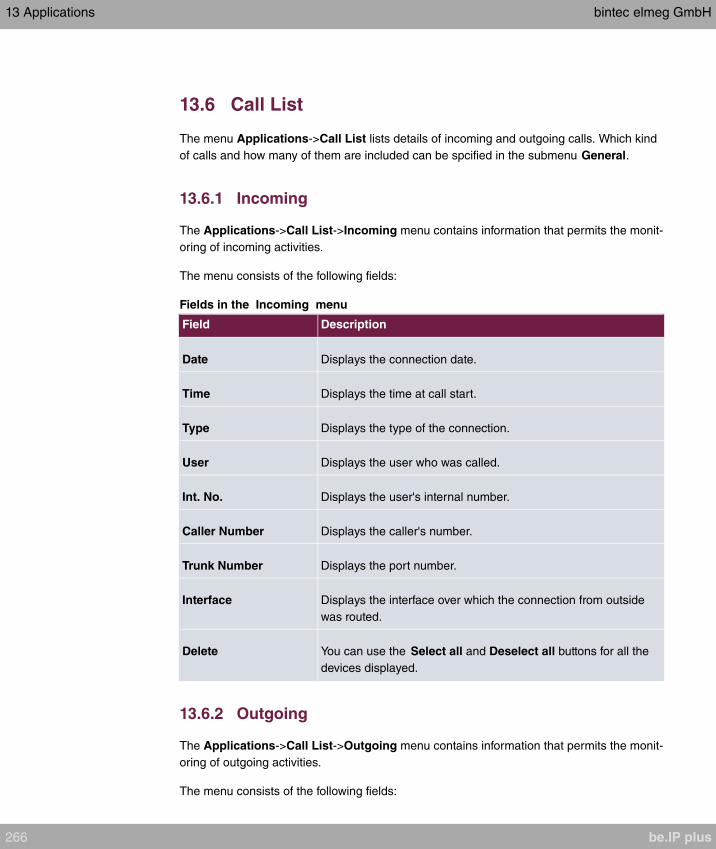
13.6 Call List
The menu Applications->Call List lists details of incoming and outgoing calls. Which kind
of calls and how many of them are included can be spcified in the submenu General.
13.6.1 Incoming
The Applications->Call List->Incoming menu contains information that permits the monit-
oring of incoming activities.
The menu consists of the following fields:
Fields in the Incoming menu
Field Description
Date Displays the connection date.
Time Displays the time at call start.
Type Displays the type of the connection.
User Displays the user who was called.
Int. No. Displays the user's internal number.
Caller Number Displays the caller's number.
Trunk Number Displays the port number.
Interface Displays the interface over which the connection from outside
was routed.
Delete You can use the Select all and Deselect all buttons for all the
devices displayed.
13.6.2 Outgoing
The Applications->Call List->Outgoing menu contains information that permits the monit-
oring of outgoing activities.
The menu consists of the following fields:
13 Applications bintec elmeg GmbH
266 be.IP plus
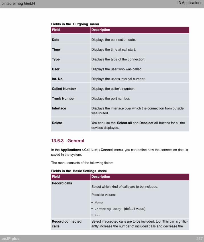
Fields in the Outgoing menu
Field Description
Date Displays the connection date.
Time Displays the time at call start.
Type Displays the type of the connection.
User Displays the user who was called.
Int. No. Displays the user's internal number.
Called Number Displays the caller's number.
Trunk Number Displays the port number.
Interface Displays the interface over which the connection from outside
was routed.
Delete You can use the Select all and Deselect all buttons for all the
devices displayed.
13.6.3 General
In the Applications->Call List->General menu, you can define how the connection data is
saved in the system.
The menu consists of the following fields:
Fields in the Basic Settings menu
Field Description
Record callsSelect which kind of calls are to be included.
Possible values:
•
• (default value)
•
Record connected
calls
Select if accepted calls are to be included, too. This can signific-
antly increase the number of included calls and decrease the
bintec elmeg GmbH 13 Applications
be.IP plus 267

Field Description
amount of time the list can cover until the maximum number of
calls is reached and the first calls are deleted from the list.
Max Call List entries
for System Calls
Specify the maximum amount of system calls that are included
in the list. The maximum number is . System calls include,
e.g., call transfers to extern, calls being accepted by an an-
nouncement, team calls that are not accepted by a single user.
Max Call List entries
per User
Specify the maximum amount of user calls (calls initated of ac-
cepted by a configured user) that are included in the list. The
maximum number is .
13.7 Mini Call Center
The mini call centre is an integrated call centre solution for up to 16 agents. It provides the
ideal solution for small groups with high dynamic telecommunication volumes (e. g insides
sales, support, order acceptance/processing, customer service). Here, a specific solution
with its own administrator has been integrated. The mini call centre is characterised by:
• Flexible allocation of agents and lines
• Dynamic adaptation according to call volume
• Call allocation with off-time for the agent
• Statistical data for agents and lines.
13.7.1 Status
In the Applications->Mini Call Center->Status menu, you can view the current status of
lines and logged-in agents in a block, along with the subscribers assigned to lines.
The menu consists of the following fields:
Values in the Status list
Field Description
View View allows you to select which call centre to display.
Line Displays the mini call centre line.
Agents assigned Displays the number of agents assigned to this line.
Agents logged on Displays the number of agents logged-in on this line.
13 Applications bintec elmeg GmbH
268 be.IP plus

Field Description
Agents in Wrap-up Displays the number of agents in post-processing time.
Active Calls Displays the number of active connections.
Waiting Calls Displays the number of waiting incoming calls.
Answered of Calls Today Displays the current number of accepted calls for this day.
Lost Calls Today Displays the current number of missed calls for this day.
13.7.2 Lines
In the Applications->Mini Call Center->Lines menu, lines are assigned to external and
internal numbers, and the name of the call centre to which the line belongs is displayed.
Choose the icon to edit existing entries. Select the New button to create new entries.
13.7.2.1 General
In the General area, you perform basic settings for a line.
The menu Applications->Mini Call Center->Lines->General consists of the following
fields:
Fields in the Basic Settings menu.
Field Description
Description Enter a description for the line.
External Number Select a number configured as mini call centre for the external
connection of this call centre line.
Internal Number Enter the desired internal number for this line.
Call Center Description Select and enter a name for the new mini call centre.
Or select the name of a mini call centre which has already been
generated.
Fields in the Further Settings menu.
bintec elmeg GmbH 13 Applications
be.IP plus 269

Field Description
Switch call signalling Select whether the call options for this line shall be switched
over a configured calendar and, if so, over which.
Possible values:
•
•
Active Variant Select which call option shall be enabled by default after config-
uration for this line.
The menu Advanced Settings consists of the following fields:
Fields in the Advanced Settings menu.
Field Description
Team Speed Timer Enter the time after which call forwarding to the next free agent
assigned to this line shall occur.
13.7.2.2 Variant 1 - 4
In the area Variant, you set up call options for the mini call centre.
The menu Applications->Mini Call Center->Lines->Variant consists of the following
fields:
Fields in the Settings menu.
Field Description
Automatic Call Pick-up
with
Select whether an incoming call shall be automatically accepted
and, if so, with which announcement or melody.
The function is activated by selecting .
The function is disabled by default.
Select the Wave file to be used for the call acceptance. All pre-
set and additionally-loaded Wave files in the system can be se-
lected.
Fields in the Rerouting Functions menu.
13 Applications bintec elmeg GmbH
270 be.IP plus
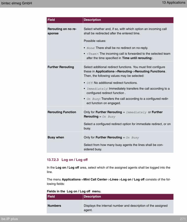
Field Description
Rerouting on no re-
sponse
Select whether and, if so, with which option an incoming call
shall be redirected after the entered time.
Possible values:
• : There shall be no redirect on no-reply.
• : The incoming call is forwarded to the selected team
after the time specified in Time until rerouting:.
Further Rerouting Select additional redirect functions. You must first configure
these in Applications->Rerouting->Rerouting Functions .
Then, the following values may be selected:
• : No additional redirect functions.
• : Immediately transfers the call according to a
configured redirect function .
• : Transfers the call according to a configured redir-
ect function on engaged.
Rerouting Function Only for Further Rerouting = or Further
Rerouting =
Select a configured redirect option for immediate redirect, or on
busy.
Busy when Only for Further Rerouting =
Select from how many busy agents the lines shall be con-
sidered busy.
13.7.2.3 Log on / Log off
In the Log on / Log off area, select which of the assigned agents shall be logged into the
line.
The menu Applications->Mini Call Center->Lines->Log on / Log off consists of the fol-
lowing fields:
Fields in the Log on / Log off menu.
Field Description
Numbers Displays the internal number and description of the assigned
agent.
bintec elmeg GmbH 13 Applications
be.IP plus 271

Field Description
Status Select whether the agent is logged into the line.
The agent is logged in by selecting .
13.7.3 Agents
In the Applications->Mini Call Center->Agents menu, lines are assigned to agents. An
agent can operate one or more mini call centre lines.
13.7.3.1 Edit or New
Choose the icon to edit existing entries. Select the New button to create new entries.
The menu Applications->Mini Call Center->Agents->New consists of the following fields:
Fields in the Basic Settings menu.
Field Description
User Select the configured user who shall serve as a call centre
agent. You configure required users in the Numbering->User
Settings->User menu.
The following users are already created:
•
•
•
•
Internal Number Select the user's internal number to be used for the call centre.
Fields in the Assigned Lines menu.
Field Description
Select lines Select the lines for which the agent shall be responsible. The
name of the corresponding call centre is displayed again when
lines are selected in order to improve the overview.
Under Assign select whether the entry should be enabled.
Fields in the Wrap-up Settings menu.
13 Applications bintec elmeg GmbH
272 be.IP plus

Field Description
Wrap-up Time Enter the time available to this agent for post-processing after
concluding a call. No further call can be assigned to this agent
during this period. The agent has the option of temporarily ex-
tending the period with a telephone procedure.
13.7.4 General
In the Applications->Mini Call Center->General menu, you can set up an HTML web in-
terface access for the mini call centre manager. The latter can then monitor the status of
lines and agents, and modify the settings for lines and agents.
The menu consists of the following fields:
Fields in the Basic Settings menu.
Field Description
Web Access Username Enter a user name for the mini call centre administrator. When a
user logs into the user interface under this name, he/she has
access to the user interface with selected parameters for admin-
istration of the call centre.
Web Access Password Enter a password for the mini call centre administrator.
13.8 Doorcom Units
You can connect a door intercom as an intercom adapter to an analogue connection of
your system.
If a door intercom adapter is connected to your system, you can speak with a visitor at the
door from every authorised telephone. You can assign particular telephones to each ring
button. These phones then ring if the ring button is pressed. On analogue telephones, the
signal on the telephone matches the intercom call. In place of the internal telephones, an
external telephone can also be configured as the call destination for the ring button. Your
door intercom can have up to 4 ring buttons. The door opener can be pressed during an in-
tercom call. It is not possible activate the door opener if an intercom call is not taking place.
bintec elmeg GmbH 13 Applications
be.IP plus 273
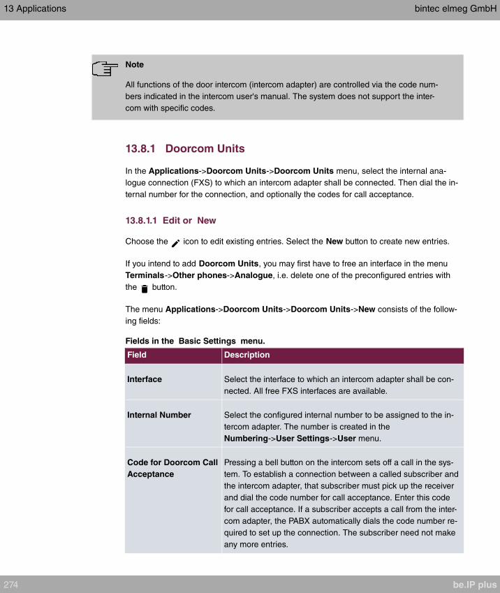
Note
All functions of the door intercom (intercom adapter) are controlled via the code num-
bers indicated in the intercom user's manual. The system does not support the inter-
com with specific codes.
13.8.1 Doorcom Units
In the Applications->Doorcom Units->Doorcom Units menu, select the internal ana-
logue connection (FXS) to which an intercom adapter shall be connected. Then dial the in-
ternal number for the connection, and optionally the codes for call acceptance.
13.8.1.1 Edit or New
Choose the icon to edit existing entries. Select the New button to create new entries.
If you intend to add Doorcom Units, you may first have to free an interface in the menu
Terminals->Other phones->Analogue, i.e. delete one of the preconfigured entries with
the button.
The menu Applications->Doorcom Units->Doorcom Units->New consists of the follow-
ing fields:
Fields in the Basic Settings menu.
Field Description
Interface Select the interface to which an intercom adapter shall be con-
nected. All free FXS interfaces are available.
Internal Number Select the configured internal number to be assigned to the in-
tercom adapter. The number is created in the
Numbering->User Settings->User menu.
Code for Doorcom Call
Acceptance
Pressing a bell button on the intercom sets off a call in the sys-
tem. To establish a connection between a called subscriber and
the intercom adapter, that subscriber must pick up the receiver
and dial the code number for call acceptance. Enter this code
for call acceptance. If a subscriber accepts a call from the inter-
com adapter, the PABX automatically dials the code number re-
quired to set up the connection. The subscriber need not make
any more entries.
13 Applications bintec elmeg GmbH
274 be.IP plus

13.8.2 Doorcom Signalling
In the Applications->Doorcom Units->Doorcom Signalling you configure the signalling
variant for call acceptance via a intercom adapter. Two intercom call options are available.
The code number for the bell button is the number the intercom adapter dials into the sys-
tem when the bell button is pressed. You can perform an internal call allocation for each
bell button. Please note that guidelines for connecting the intercom adapter depend on the
respective manufacturer. For this, read the operating instructions provided by the manufac-
turer of the intercom adapter.
13.8.2.1 General
In the General area you set up the basic features of intercom signalling.
The menu Applications->Doorcom Units->Doorcom Signalling->General consists of
the following fields:
Fields in the Basic Settings menu.
Field Description
Description Select one of the configured intercom settings previously cre-
ated in the Applications->Doorcom Units->Doorcom Units
menu.
Bell ID Enter an unambiguous four-digit code for the bell. Pressing a
bell button on the intercom adapter initiates a call to the termin-
als entered in the assigned intercom call option.
Bell Name Enter a name for the bell.
Switch signalling Select whether the intercom call options for this bell shall be
switched over a configured calendar and, if so, over which. For
every ring, you can create up to two intercom call variants in the
Applications->Doorcom Units->Doorcom
Signalling->New->Variant menu.
Possible values:
•
•
Active Doorcom Vari-
ant
Select which intercom call option shall be enabled by default for
this bell after configuration.
bintec elmeg GmbH 13 Applications
be.IP plus 275

The menu Advanced Settings consists of the following fields:
Fields in the Advanced Settings menu.
Field Description
Call Signalisation
Timer
Enter the time in seconds for which the door intercom call shall
be signalled. The default value is 40 seconds.
Team Speed Timer Here, enter the Team Speed Timer following which call for-
warding after time shall be performed. The default value is 15
seconds.
Simultaneous after
time
It is possible for all numbers assigned to this door intercom sig-
nalling to be called simultaneously after a specified time.
The default value is 60 seconds.
13.8.2.2 Doorcom Signalling Variant 1 and 2
In the Doorcom Signalling Variant area, you configure both intercom call options for this
signalling profile.
The Applications->Doorcom Units->Doorcom Signalling->Intercom call variant con-
sists of the following fields:
Fields in the Basic Settings menu.
Field Description
Assignment Select where pressing of the bell button shall be signalled.
Possible values:
• : Signalling occurs on an internal number.
• : Signalling occurs to an external number.
Internal Assignment Select the internal numbers on which pressing of the door bell
shall be signalled. With Add you add an internal number.
External Assignment Enter the external telephone number to which pressing the door
bell shall be signalled.
Signalling You can call the internal number with a broadcast call.
Possible values:
13 Applications bintec elmeg GmbH
276 be.IP plus
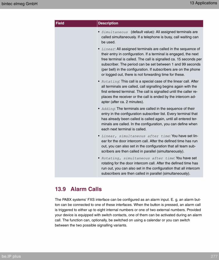
Field Description
• (default value): All assigned terminals are
called simultaneously. If a telephone is busy, call waiting can
be used.
• : All assigned terminals are called in the sequence of
their entry in configuration. If a terminal is engaged, the next
free terminal is called. The call is signalled ca. 15 seconds per
subscriber. The period can be set between 1 and 99 seconds
(per bell) in the configuration. If subscribers are on the phone
or logged out, there is not forwarding time for these.
• : This call is a special case of the linear call. After
all terminals are called, call signalling begins again with the
first entered terminal. The call is signalled until the caller re-
places the receiver or the call is ended by the intercom ad-
apter (after ca. 2 minutes).
• : The terminals are called in the sequence of their
entry in the configuration subscriber list. Every terminal that
has already been called is called again, until all entered ter-
minals are called. In the configuration, you can define when
each next terminal is called.
• : You have set lin-
ear for the door intercom call. After the defined time has run
out, you can also set in the configuration that all team sub-
scribers are then called in parallel (simultaneously).
• : You have set
rotating for the door intercom call. After the defined time has
run out, you can also set in the configuration that all intercom
subscribers are then called in parallel (simultaneously).
13.9 Alarm Calls
The PABX systems' FXS interface can be configured as an alarm input. E. g. an alarm but-
ton can be connected to one of these interfaces. When the button is pressed, an alarm call
is triggered to either up to eight internal numbers or one of two external numbers. Provided
your device is equipped with switch contacts, one of them can be activated during an alarm
call. The function can, optionally, be switched on using a calendar or you can switch
between the two possible signalling variants.
bintec elmeg GmbH 13 Applications
be.IP plus 277
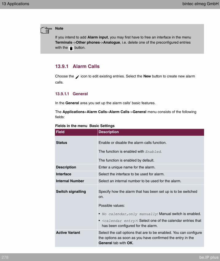
Note
If you intend to add Alarm input, you may first have to free an interface in the menu
Terminals->Other phones->Analogue, i.e. delete one of the preconfigured entries
with the button.
13.9.1 Alarm Calls
Choose the icon to edit existing entries. Select the New button to create new alarm
calls.
13.9.1.1 General
In the General area you set up the alarm calls' basic features.
The Applications+Alarm Calls+Alarm Calls->General menu consists of the following
fields:
Fields in the menu Basic Settings
Field Description
Status Enable or disable the alarm calls function.
The function is enabled with .
The function is enabled by default.
Description Enter a unique name for the alarm.
Interface Select the interface to be used for alarm.
Internal Number Select an internal number to be used for the alarm.
Switch signalling Specify how the alarm that has been set up is to be switched
on.
Possible values:
• : Manual switch is enabled.
• : Select one of the calendar entries that
has been configured for the alarm.
Active Variant Select the call options that are to be enabled. You can configure
the options as soon as you have confirmed the entry in the
General tab with OK.
13 Applications bintec elmeg GmbH
278 be.IP plus

The menu Advanced Settings consists of the following fields:
Fields in the menu Advanced Settings
Field Description
Alarm Signalling Peri-
od
Enter the length of time for which an alarm is to be signalled, in
seconds.
The default value is seconds.
Repeat after Specify the time between the alarm repeats, in seconds.
A value of between and seconds is possible.
The default value is seconds.
Call repeats are not possible via an FXO interface (if an FXO in-
terface is available).
Number of repeats Specify the number of repeats if the alarm is not taken.
A value of between 1 and 10 repeats is possible.
The default value is .
Call repeats are not possible via an FXO interface (if an FXO in-
terface is available).
External Connection
Timer
Specify the maximum duration of an external call once it has
been accepted (in seconds).
A value of between and seconds is possible.
The default value is seconds.
Info Message (UUS1) Optionally, a message (max. 32 characters) can be sent to
ISDN terminals.
Relay ContactOnly applicable if your device is equipped with a relais!
If a relay is to be switched on during the alarm: Select the relay
that is to be used. Configuration of the Relay is done in the
menu Physical Interfaces->Relay.
Wave-File Select whether and which saved WAV file is to be played when
the alarm call is taken.
Possible values:
bintec elmeg GmbH 13 Applications
be.IP plus 279
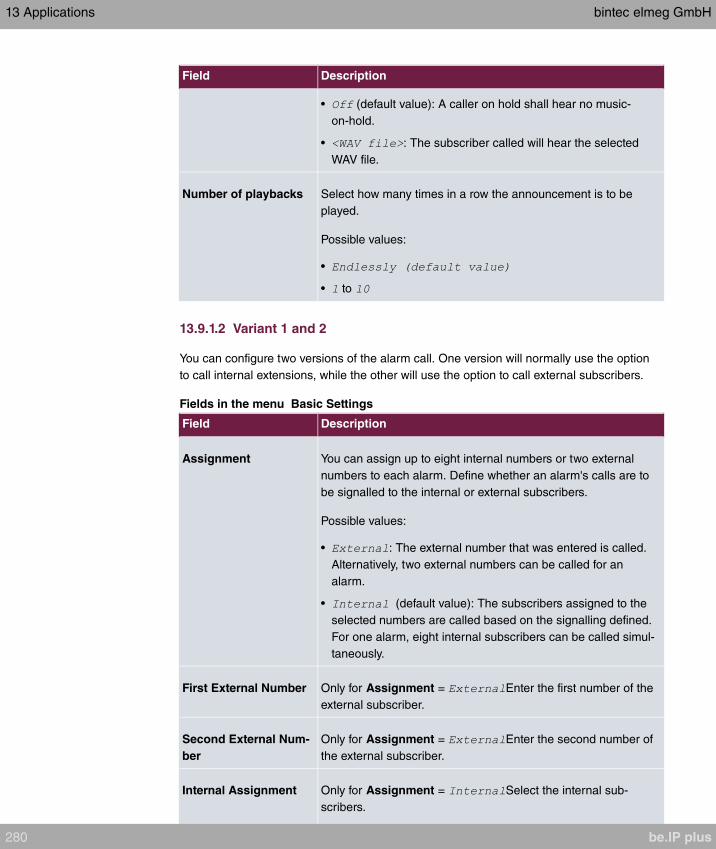
Field Description
• (default value): A caller on hold shall hear no music-
on-hold.
• : The subscriber called will hear the selected
WAV file.
Number of playbacks Select how many times in a row the announcement is to be
played.
Possible values:
•
• to
13.9.1.2 Variant 1 and 2
You can configure two versions of the alarm call. One version will normally use the option
to call internal extensions, while the other will use the option to call external subscribers.
Fields in the menu Basic Settings
Field Description
Assignment You can assign up to eight internal numbers or two external
numbers to each alarm. Define whether an alarm's calls are to
be signalled to the internal or external subscribers.
Possible values:
• : The external number that was entered is called.
Alternatively, two external numbers can be called for an
alarm.
• (default value): The subscribers assigned to the
selected numbers are called based on the signalling defined.
For one alarm, eight internal subscribers can be called simul-
taneously.
First External Number Only for Assignment = Enter the first number of the
external subscriber.
Second External Num-
ber
Only for Assignment = Enter the second number of
the external subscriber.
Internal Assignment Only for Assignment = Select the internal sub-
scribers.
13 Applications bintec elmeg GmbH
280 be.IP plus

Field Description
Use Add to add more internal numbers.
13.10 Voice Mail System
The voicemail system is an intelligent answering machine for those who use your PABX.
An individual voicemail box can be configured for each extension. All subscribers can hear,
save or delete their messages from any telephone using a personal PIN code.
Subscribers can have themselves informed of incoming e-mails. Recorded messages can
be automatically transferred to any e-mail address.
General settings of the voicemail system are performed on your PABX. Operation of the in-
dividual voicemail boxes occurs via telephone.
Every subscriber can use her individual voicemail box by transferring calls to her voicemail
box.
Note
If you wish to use a voicemail box, you'll need an installed SD card (if supportted by
you device). You may need load the required folder structure with the announcement
texts on the SD card. Choose in the Maintenance->Software &Configuration menu
the option .
Caution
Do not remove the SD card during any read or write access to avoid losing data or
damaging the card. Watch the relevant LED on the top of the device: it will flicker dur-
ing any read or write access.
13.10.1 Voice Mail Boxes
In the Applications->Voice Mail System ->Voice Mail Boxes menu, a list of the individual
voicemail boxes for specific subscribers is displayed.
Only for compact systems.
Two predefined voicemail boxes are displayed:
bintec elmeg GmbH 13 Applications
be.IP plus 281
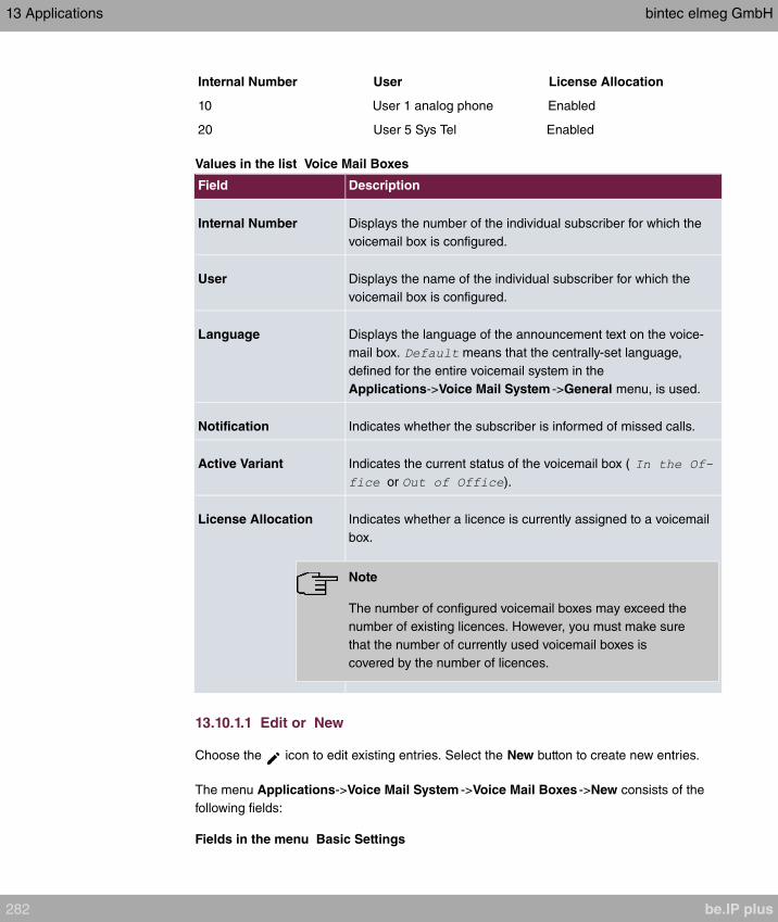
Internal Number User License Allocation
10 User 1 analog phone Enabled
20 User 5 Sys Tel Enabled
Values in the list Voice Mail Boxes
Field Description
Internal Number Displays the number of the individual subscriber for which the
voicemail box is configured.
User Displays the name of the individual subscriber for which the
voicemail box is configured.
Language Displays the language of the announcement text on the voice-
mail box. means that the centrally-set language,
defined for the entire voicemail system in the
Applications->Voice Mail System ->General menu, is used.
Notification Indicates whether the subscriber is informed of missed calls.
Active Variant Indicates the current status of the voicemail box (
or ).
License Allocation Indicates whether a licence is currently assigned to a voicemail
box.
Note
The number of configured voicemail boxes may exceed the
number of existing licences. However, you must make sure
that the number of currently used voicemail boxes is
covered by the number of licences.
13.10.1.1 Edit or New
Choose the icon to edit existing entries. Select the New button to create new entries.
The menu Applications->Voice Mail System ->Voice Mail Boxes ->New consists of the
following fields:
Fields in the menu Basic Settings
13 Applications bintec elmeg GmbH
282 be.IP plus
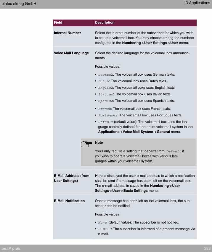
Field Description
Internal Number Select the internal number of the subscriber for which you wish
to set up a voicemail box. You may choose among the numbers
configured in the Numbering->User Settings->User menu.
Voice Mail Language Select the desired language for the voicemail box announce-
ments.
Possible values:
• : The voicemail box uses German texts.
• : The voicemail box uses Dutch texts.
• : The voicemail boxe uses English texts.
• : The voicemail box uses Italian texts.
• : The voicemail box uses Spanish texts.
• : The voicemail box uses French texts.
• : The voicemail box uses Portugues texts.
• (default value): The voicemail box uses the lan-
guage centrally defined for the entire voicemail system in the
Applications->Voice Mail System ->General menu.
Note
You'll only require a setting that departs from if
you wish to operate voicemail boxes with various lan-
guages within your voicemail system.
E-Mail Address (from
User Settings)
Here is displayed the user e-mail address to which a notification
shall be sent if a message has been left on the voicemail box.
The e-mail address in saved in the Numbering->User
Settings->User->Basic Settings menu.
E-Mail Notification Once a message has been left on the voicemail box, the sub-
scriber can be notified.
Possible values:
• (default value): The subscriber is not notified.
• : The subscriber is informed of a present message via
e-mail.
bintec elmeg GmbH 13 Applications
be.IP plus 283
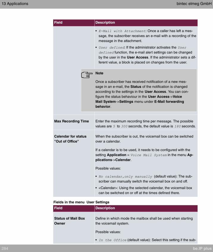
Field Description
• : Once a caller has left a mes-
sage, the subscriber receives an e-mail with a recording of the
message in the attachment.
• : If the administrator activates the
function, the e-mail alert settings can be changed
by the user in the User Access. If the administrator sets a dif-
ferent value, a block is placed on changes from the user.
Note
Once a subscriber has received notification of a new mes-
sage in an e-mail, the Status of the notification is changed
according to the settings in the User Access. You can con-
figure the status behaviour in the User Access->Voice
Mail System->Settings menu under E-Mail forwarding
behavior.
Max Recording Time Enter the maximum recording time per message. The possible
values are to seconds, the default value is seconds.
Calendar for status
"Out of Office"
When the subscriber is out, the voicemail box can be switched
over a calendar.
If a calendar is to be used, it needs to be configured with the
setting Application = in the menu Ap-
plications->Calendar.
Possible values:
• (default value): The sub-
scriber can manually switch the voicemail box on and off.
• <Calendar>: Using the selected calendar, the voicemail box
can be switched on or off at the times defined there.
Fields in the menu User Settings
Field Description
Status of Mail Box
Owner
Define in which mode the mailbox shall be used when starting
the voicemail system.
Possible values:
• (default value): Select this setting if the sub-
13 Applications bintec elmeg GmbH
284 be.IP plus

Field Description
scriber is in the office when the voicemail system is started.
• : Select this setting if the subscriber is out of
office when the voicemail system is started.
Check PIN Select whether the currently configured voicemail box should be
protected with a PIN.
The function is enabled with .
The function is disabled by default.
You can change the PIN for the personal voice box in the Num-
bering->User Settings->Users->Authorizations under PIN
for Phone Access.
Mode for status "In the
Office"
The voicemail box can be operated with two different settings
during office hours.
Possible values:
• (default value): A caller hears
an announcement and can leave a message.
• : A caller hears an announcement, but
cannot leave a message.
Mode for status "Out
of Office"
The voicemail box can be operated with two different settings
outside of office hours.
Possible values:
• (default value): A caller hears an an-
nouncement, but cannot leave a message.
• : A caller hears an announce-
ment and can leave a message.
Select the icon to set up your own voice announcements for the selected voice mail box
in addition to the settings above.
The Applications->Voice Mail System ->Voice Mail Boxes -> menu consists of the fol-
lowing fields:
Fields in the menu Voice Announcement
bintec elmeg GmbH 13 Applications
be.IP plus 285

Feld Beschreibung
In the Office You can upload your own announcement for the In the Office
state. Use the WAV file format for this annoncement.
Click New Message to upload the file. The window Annouce-
ment Options opens.
If an announcement has been stored, use the icon to play
the announcement, the icon to delete it.
Out of Office You can upload your own announcement for the Out of Office
state. Use the WAV file format for this annoncement.
Click New Message to upload the file. The window Annouce-
ment Options opens.
If an announcement has been stored, use the icon to play
the announcement, the icon to delete it.
Fields in the menu Annoucement Options
Feld Beschreibung
Action Displays .
Source Location For Action =
Select the WAV file to be used for the announcement and click
Start to upload.
13.10.2 Status
In the Applications->Voice Mail System ->Status menu, the status of the individual voice-
mail boxes for specific subscribers is indicated. You can see how many calls have gone in-
to which voicemail box, and how many "old" calls are already present.
Values in the System Messages list
Field Description
Internal Number Displays the number of the individual subscriber for which the
voicemail box is configured.
User Displays the name of the individual subscriber for which the
voicemail box is configured.
13 Applications bintec elmeg GmbH
286 be.IP plus

Field Description
New Calls Displays the calls which have not yet been listened to by the
subscriber.
Old Calls Displays the calls which have already been listened to or stored
by the subscriber.
Note
By default, the system can record a maximum of 59 calls per voicemail box. You can-
not change this value in the GUI.
13.10.3 General
In this menu, you can configure the general settings for your voicemail system.
The menu Applications->Voice Mail System ->General consists of the following fields:
Fields in the menu Basic Settings
Field Description
Voice Mail System Select whether to activate your voicemail system.
The function is enabled with .
The function is enabled by default.
Description Only for Voice Mail System enabled.
Enter a description for your voicemail system. This description
is displayed on the telephone when a call goes in to the voice
mail system.
The default value is .
Internal Number Only for Voice Mail System enabled.
Enter the internal number under which to access your voicemail
system.
The default value is .
Language Select the language for the entire voicemail system.
bintec elmeg GmbH 13 Applications
be.IP plus 287

Field Description
Possible values:
• (default value)
•
•
•
•
•
•
Diverging from the language set here, a language can be indi-
vidually set for each voice mail box in the Applications+Voice
Mail System->Voice Mail Boxes ->New menu.
Fields in the menu Mail Settings
Field Description
SMTP Server Enter the address (IP address or valid DNS name) of the e-mail
server to be used for sending the e-mails.
Return Address Enter any address to be used as sender when sending e-mails.
This address merely serves to identify e-mails in the inbox.
SMTP User Name Enter the user name for the SMTP server.
SMTP Password Enter the password for the SNMP server user.
The menu Advanced Settings consists of the following fields:
Fields in the menu Advanced Settings
Field Description
Lifetime Voicemail messages are deleted after an adjustable period of
time.
Possible values are to days. The default value is .
Non-standard SMTP
Server Port
Enter the port to be used for sending e-mails.
The default value is .
13 Applications bintec elmeg GmbH
288 be.IP plus

Chapter 14 LAN
In this menu, you configure the addresses in your LAN and can structure your local network
using VLANs.
14.1 IP Configuration
In this menu, you can edit the IP configuration of the LAN and Ethernet interfaces of your
device.
14.1.1 Interfaces
The existing IP interfaces are listed in the LAN->IP Configuration->Interfaces menu. You
can edit the IP configuration of the interfaces or create virtual interfaces for special applica-
tions. Here is a list of all of the interfaces (logical Ethernet interfaces and others created in
the subsystems) configured in the System Management->Interface Mode / Bridge
Groups->Interfaces menu.
Use the to edit the settings of an existing interface (bridge groups, Ethernet interfaces in
routing mode).
You can use the New button to create virtual interfaces. However, this is only needed in
special applications (e.g. BRRP).
Depending on the option selected, different fields and options are available. All the config-
uration options are listed below.
Change the status of the interface by clicking the or the button in the Action column.
Press the button to display the details of an existing interface.
Note
For IPv4 note that:
If your device has obtained an IP address dynamically from a DHCP server operated
in your network for the basic configuration, the default IP address is deleted automatic-
ally and your device will no longer function over this address.
However, if you have set up a connection to the device over the default IP address or
have assigned an IP address with the Dime Manager in the basic configuration, you
bintec elmeg GmbH 14 LAN
be.IP plus 289
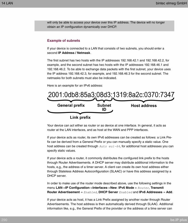
will only be able to access your device over this IP address. The device will no longer
obtain an IP configuration dynamically over DHCP.
Example of subnets
If your device is connected to a LAN that consists of two subnets, you should enter a
second IP Address / Netmask.
The first subnet has two hosts with the IP addresses 192.168.42.1 and 192.168.42.2, for
example, and the second subnet has two hosts with the IP addresses 192.168.46.1 and
192.168.46.2. To be able to exchange data packets with the first subnet, your device uses
the IP address 192.168.42.3, for example, and 192.168.46.3 for the second subnet. The
netmasks for both subnets must also be indicated.
Here is an example for an IPv6 address:
Your device can act either as router or as device at one interface. In general, it acts as
router at the LAN interfaces, and as host at the WAN and PPP interfaces.
If your device acts as router, its own IPv6 addresses can be created as follows: a Link Pre-
fix can be derived from a General Prefix or you can manually specify a static value. One
host address can be created through , for additional host addresses you can
specify static values.
If your device acts a router, it commonly distributes the configured link prefix to the hosts
through Router Advertisements. A DHCP server may distribute additional information to the
hosts, e,g., the address of a timer server. A client can create its own host address either
through Stateless Address Autoconfiguration (SLAAC) or have this address assigned by a
DHCP server.
In order to make use of the router mode described above, use the following settings in the
menu LAN->IP Configuration->Interfaces->New: IPv6 Mode = , Transmit
Router Advertisement = , DHCP Server and IPv6 Addresses = Add.
If your device acts as host, it has a Link Prefix assigned by another router through Router
Advertisements. The host address is then automatically derived through SLAAC. Additional
information like, e.g., the General Prefix of the provider or the address of a time server can
14 LAN bintec elmeg GmbH
290 be.IP plus

be received through DHCP. Use the following settings in the menu LAN->IP
Configuration->Interfaces->New: IPv6 Mode = , Accept Router Advertisement
= and DHCP Client = .
14.1.1.1 Edit or New
Choose the icon to edit existing entries. Choose the New button to create virtual inter-
faces.
The LAN->IP Configuration->Interfaces->/New menu consists of the following fields:
Fields in the Basic Parameters menu.
Field Description
Based on Ethernet In-
terface
This field is only displayed if you are editing a virtual routing in-
terface.
Select the Ethernet interface for which the virtual interface is to
be configured.
Interface Mode Only for physical interfaces in routing mode and for virtual inter-
faces.
Select the configuration mode of the interface.
Possible values:
• (default value): The interface is not assigned for
a specific purpose.
• : This option only applies for routing inter-
faces.
You use this option to assign the interface to a VLAN. This is
done using the VLAN ID, which is displayed in this mode and
can be configured. The definition of a MAC address in MAC
Address is optional in this mode.
VLAN ID Only for Interface Mode =
This option only applies for routing interfaces. Assign the inter-
face to a VLAN by entering the VLAN ID of the relevant VLAN.
Possible values are (default value) to .
MAC Address Enter the MAC address associated with the interface. For virtual
bintec elmeg GmbH 14 LAN
be.IP plus 291

Field Description
interfaces, you can use the MAC address of the physical inter-
face under which the virtual interface was created by activating
Use built-in, but VLAN IDs must be different. You can also al-
locate a virtual MAC address. The first 6 characters of the MAC
are preset (but can be changed).
If Use built-in is active, the predefined MAC address of the al-
located physical interface is used.
Use built-in is activated by default.
Fields in the Basic IPv4 Parameters menu.
Field Description
Security Policy Select the security settings to be used with the interface.
Possible values:
• : All IP packets are allowed through except for
those which are explicitly prohibited..
• : Only those packets are transmitted that can be
attributed to a connection that has been initiated from a trus-
ted zone.
You can configure exceptions for the selected setting in the
Firewall on page 518 menu.
Address Mode Select how an IP address is assigned to the interface.
Possible values:
• (default value): The interface is assigned a static IP
address in IP Address / Netmask.
• : An IP address is assigned to the interface dynamically
via DHCP.
DHCP Metric It is possible to assign a metric for gateway route received by an
interface via DHCP. This may be necessary when configuring
backup connections to ensure a clean switch to the backup and
back again.
The default value is . In case of a backup solution, this option
should be set to a higher value so the backup route does not re-
ceive a too high priority.
14 LAN bintec elmeg GmbH
292 be.IP plus

Field Description
IP Address / Netmask Only for Address Mode =
With Add, add a new address entry, enter the IP Address and
the corresponding Netmask of the virtual interface.
Fields in the Basic IPv6 Parameters menu.
Field Description
IPv6Select whether this interface should use Internet Protocol ver-
sion 6 (IPv6) for data transmission.
The function is activated by selecting .
The function is disabled by default.
Security Policy Only for IPv6 =
Select the security settings to be used with the interface.
Possible values:
• (default value): All IP packets are allowed through
except for those which are explicitly prohibited.
We recommend you use this setting if you want to use IPv6
on your LAN.
• : Only those packets are transmitted that can be
attributed to a connection that has been initiated from a trus-
ted zone.
We recommend you use this setting if you want to use IPv6
outside of your LAN.
You can configure exceptions for the selected setting in the
Firewall on page 518 menu.
IPv6 Mode Only for IPv6 =
Select whether the interface is to be operated in host or in
router mode. Depending on your selection different parameters
are presented for you to configure.
Possible values:
• (default
value): Select whether Router Advertisements are to be sent
via the interface.
bintec elmeg GmbH 14 LAN
be.IP plus 293

Field Description
Using Router Advertisements the list of prefixes is propagated
and the router propagates itself as the standard gateway.
The function is activated by selecting .
The function is enabled by default.
• : The interface is operated in host mode.
DHCP Server Only for IPv6 = and IPv6 Mode =
Specify if your device is to act as DHCP server, i.e., if it is to
transmit DHCP options in order to distribute information about
the DNS servers to the clients.
Enable this option if hosts are to create IPv6 addresses through
SLAAC.
The function is activated by selecting .
The function is enabled by default.
IPv6 Addresses Only for IPv6 =
You can assign IPv6 Addresses to the selected interface..
Add allows you to create one or more address entries.
A new windows opens that allows you to specify an IPv6 ad-
dress consisting of a Link Prefix and a host identifier.
If your device operates in host mode (IPv6 Mode = , Ac-
cept Router Advertisement and DHCP Client =
), its IPv6 addresses are determined through SLAAC.
You need not configure an IPv6 address manually, but you can
enter addtional addresses if desired.
If your device is operating in router mode ( IPv6 Mode =
, Transmit Router
Advertisement = and DHCP Server = ),
you need to configure its IPv6 addresses here.
Accept Router Advert-
isement Only for IPv6 = and IPv6 Mode =
14 LAN bintec elmeg GmbH
294 be.IP plus

Field Description
Select if Router Advertisements are to be received on the selec-
ted interface. Router Advertisements are used, e.g., to create
the prefix list.
The function is activated by selecting .
The function is enabled by default.
DHCP ClientOnly for IPv6 = and IPv6 Mode =
Select if your device is to act as DHCP client, i.e., if it is to re-
ceive DHCP options in order to obtain information about the
DNS servers.
The function is activated by selecting .
The function is enabled by default.
Use Add to create more entries.
Fields in the Basic Parameters menu.
Field Description
AdvertiseOnly for IPv6 Mode =
Here you can determine if the prefix being defined in the current
window is propagated per Router Advertisement over the selec-
ted interface.
The function is activated by selecting .
The function is enabled by default.
Fields in the Link Prefix menu.
Field Description
Setup ModeSelect in which way the Link Prefix is to be determined.
Possible values:
• (default value): The Link Prefix is
derived from a General Prefix.
• : You can enter the link prefix.
bintec elmeg GmbH 14 LAN
be.IP plus 295
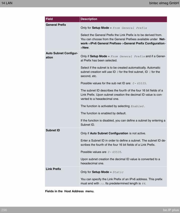
Field Description
General PrefixOnly for Setup Mode =
Select the General Prefix the Link Prefix is to be derived from.
You can choose from the General Prefixes available under Net-
work->IPv6 General Prefixes->General Prefix Configuration -
>New.
Auto Subnet Configur-
ation Only if Setup Mode = and if a Gener-
al Prefix has been selected.
Select if the subnet is to be created automatically. Automatic
subnet creation will use ID for the first subnet, ID for the
second, etc.
Possible values for the sub net ID are: - .
The subnet ID describes the fourth of the four 16 bit fields of a
Link Prefix. Upon subnet creation the decimal ID value is con-
verted to a hexadecimal one.
The function is activated by selecting .
The function is enabled by default.
If the function is disabled, you can define a subnet by entering a
Subnet ID.
Subnet IDOnly if Auto Subnet Configuration is not active.
Enter a Subnet ID in order to define a subnet. The subnet ID de-
scribes the fourth of the four 16 bit fields of a Link Prefix.
Possible values are - .
Upon subnet creation the decimal ID value is converted to a
hexadecimal one.
Link PrefixOnly for Setup Mode =
You can specify the Link Prefix of an IPv6 address. This prefix
must end with . Its predetermined length is .
Fields in the Host Address menu.
14 LAN bintec elmeg GmbH
296 be.IP plus

Field Description
Generation ModeDetermine if the Host Identifier of the IPv6 address is to be
automatically derived from the MAC address through EUI-64.
The function is activated by selecting .
The function is enabled by default.
EUI-64 triggers the following process:
• The hexadecimal 48 bit MAC address is split into 2 x 24 bit.
• is inserted into the created gap in order to obtain 64 bit.
• The hexadecimal notation of the 64 bit is converted to a bin-
ary notation.
• Bit no. 7 of the first 8 bit field is set to .
Static AddressesIndependently of the automatic creation described under Gen-
eration Mode, you can manually specify the Host Identifier of
one or more IPv6 addresses with Add. Its predefined length is
. Start any entry with .
The fields in the Advanced menu are part if the prefix information sent inside of Router Ad-
vertisements if Advertise is enabled. The menu Advanced consists of the following fields:
Fields in the Advanced IPv6 Settings menu
Field Description
On Link Flag Select whether the On-Link Flag (L-Flag) should be set. This al-
lows the host to enter the prefix from the prefix list.
The function is activated by selecting .
The function is enabled by default.
Autonomous Flag Select whether the Autonomous Address Configuration Flag
(A-Flag) should be set. This allows the host to use the prefix
and the 64 bit interface ID, to derive its address.
The function is activated by selecting .
The function is enabled by default.
Preferred LifetimeEnter a time period in seconds. During this time, addresses de-
rived from the prefix through SLAAC are preferred.
The default value is seconds.
bintec elmeg GmbH 14 LAN
be.IP plus 297

Field Description
Valid LifetimeEnter a time period in seconds, for which the prefix is valid.
The default value is seconds.
Note
The value for the valid lifetime should be lower than the one
configured for the option Router Lifetime under Advanced
IPv6 Settings.
The menu Advanced Settings consists of the following fields:
Fields in the Advanced IPv4 Settings menu.
Field Description
DHCP MAC Address Only for Address Mode =
If Use built-in is activated (default setting), the hardware MAC
address of the Ethernet interface is used. In the case of physical
interfaces, the current MAC address is entered by default.
If you disable Use built-in, you enter an MAC address for the
virtual interface, e.g. .
Some providers use hardware-independent MAC addresses to
allocate their clients IP addresses dynamically. If your provider
has assigned you a MAC address, enter this here.
DHCP Hostname Only for Address Mode =
Enter the host name requested by the provider. The maximum
length of the entry is 45 characters.
DHCP Broadcast FlagOnly for Address Mode =
Choose whether or not the BROADCAST bit is set in the DHCP
requests for your device. Some DHCP servers that assign IP
addresses by UNICAST do not respond to DHCP requests with
the set BROADCAST bit. In this case, it is necessary to send
DHCP requests in which this bit is not set. In this case, disable
this option.
The function is activated by selecting .
14 LAN bintec elmeg GmbH
298 be.IP plus

Field Description
The function is enabled by default.
Create Default RouteOnly for Address Mode =
Select, whether a default route is to be defined for this interface.
The function is activated by selecting .
The function is enabled by default.
Proxy ARP Select whether your device is to respond to ARP requests from
its own LAN on behalf of defined remote terminals.
The function is activated by selecting .
The function is disabled by default.
TCP-MSS Clamping Select whether your device is to apply MSS Clamping. To pre-
vent IP packets fragmenting, the MSS (Maximum Segment
Size) is automatically decreased by the device to the value set
here.
The function is activated by selecting .
The function is disabled by default. Once enabled, the default
value is entered in the input field.
Fields in the Advanced IPv6 Settings menu
Field Description
Router Lifetime Only for IPv6 = , IPv6 Mode =
and Transmit Router Advertise-
ment =
Enter a time period in seconds. The router remains in the de-
fault router list throughout this interval.
The default value is seconds. The maximum value is
seconds. A value of means that the router is not a
default router, and will not be entered in the default router list.
bintec elmeg GmbH 14 LAN
be.IP plus 299

Field Description
Note
The value for the Router Lifetime should be higher than
the shortest valid lifetime for a link prefix configured for this
interface under Basic IPv6 Parameters.
Router Preference Only for IPv6 = , IPv6 Mode =
and Transmit Router Advertise-
ment =
Select your router's preference for choice of default router. This
is useful for cases where a node receives advertisements from
multiple routers, or for back-up scenarios.
Possible values:
•
• (default value)
•
DHCP Mode Only for IPv6 = , IPv6 Mode =
and Transmit Router Advertise-
ment =
Select the information to be forwarded to the DHCP client.
Note
To achieve this, your router must not be set up as a DHCP
server.
By selecting
(default value) no address- related information, such
as i.e. DNS, VoIP, etc., is passed through.
Enable this option if hosts inside of the network are to automat-
ically create their IP addresses through SLAAC. In this case, the
router sends only data via DHCP that are not address-related.
By selecting
hosts receive IPv6 addresses as well as not address-related in-
formation through DHCP.
14 LAN bintec elmeg GmbH
300 be.IP plus
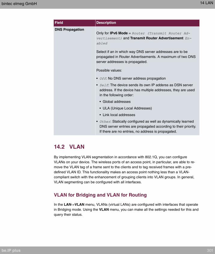
Field Description
DNS PropagationOnly for IPv6 Mode =
and Transmit Router Advertisement
Select if an in which way DNS server addresses are to be
propagated in Router Advertisements. A maximum of two DNS
server addresses is propagated.
Possible values:
• : No DNS server address propagation
• : The device sends its own IP adderss as DSN server
address. If the device has multiple addresses, they are used
in the following order:
• Global addresses
• ULA (Unique Local Addresses)
• Link local addresses
• : Statically configured as well as dynamically learned
DNS server entries are propagated according to their priority.
If there are no entries, no address is propagated.
14.2 VLAN
By implementing VLAN segmentation in accordance with 802.1Q, you can configure
VLANs on your device. The wireless ports of an access point, in particular, are able to re-
move the VLAN tag of a frame sent to the clients and to tag received frames with a pre-
defined VLAN ID. This functionality makes an access point nothing less than a VLAN-
compliant switch with the enhancement of grouping clients into VLAN groups. In general,
VLAN segmenting can be configured with all interfaces.
VLAN for Bridging and VLAN for Routing
In the LAN->VLAN menu, VLANs (virtual LANs) are configured with interfaces that operate
in Bridging mode. Using the VLAN menu, you can make all the settings needed for this and
query their status.
bintec elmeg GmbH 14 LAN
be.IP plus 301

Caution
For interfaces that operate in Routing mode, you only assign a VLAN ID to the inter-
face. You define this via the parameters Interface Mode = and field
VLAN ID in menu LAN->IP Configuration->Interfaces->New.
14.2.1 VLANs
In this menu, you can display all the VLANs already configured, edit your settings and cre-
ate new VLANs. By default, the VLAN with VLAN Identifier = is available,
to which all interfaces are assigned.
14.2.1.1 Edit or New
Choose the icon to edit existing entries. Select the New button in order to create new
VLANs.
The LAN->VLAN->VLANs->New menu consists of the following fields:
Fields in the Configure VLAN menu.
Field Description
VLAN Identifier Enter the number that identifies the VLAN. In the menu, you
can no longer change this value.
Possible values are (default value) to .
VLAN Name Enter a unique name for the VLAN. A character string of up to
32 characters is possible.
The predefined VLAN name is .
VLAN Members Select the ports that are to belong to this VLAN. You can use
the Add button to add members.
For each entry, also select whether the frames to be transmitted
from this port are to be transmitted (i.e. with VLAN in-
formation) or (i.e. without VLAN information).
14.2.2 Port Configuration
In this menu, you can define and view the rules for receiving frames at the VLAN ports.
14 LAN bintec elmeg GmbH
302 be.IP plus

The LAN->VLANs->Port Configuration menu consists of the following fields:
Fields in the Port Configuration menu.
Field Description
Interface Shows the port for which you define the PVID and processing
rules.
PVID Assign the selected port the required PVID (Port VLAN Identifi-
er).
If a packet without a VLAN tag reaches this port, it is assigned
this PVID.
Drop untagged frames If this option is enabled, untagged frames are discarded. If the
option is disabled, untagged frames are tagged with the PVID
defined in this menu.
Drop non-members If this option is enabled, all tagged frames that are tagged with a
VLAN ID to which the selected port does not belong are dis-
carded.
14.2.3 Administration
In this menu, you make general settings for a VLAN. The options must be configured sep-
arately for each bridge group.
The LAN->VLANs->Administrationmenu consists of the following fields:
Fields in the Bridge Group br<ID> VLAN Options menu
Field Description
Enable VLAN Enable or disable the specified bridge group for VLAN.
The function is enabled with .
The function is not activated by default.
bintec elmeg GmbH 14 LAN
be.IP plus 303

Chapter 15 Wireless LAN
In the case of wireless LAN or Wireless LAN (WLAN = Wireless Local Area Network), this
relates to the creation of a network using wireless technology.
Network functions
Like a wired network, a WLAN offers all the main network functions. Access to servers,
files, printers, and the e-mail system is just as reliable as company-wide Internet access.
Because the devices do not require any cables, the great advantage of WLAN is that there
are no building-related restrictions (i.e. the device location does not depend on the position
and number of connections).
Currently applicable standard: IEEE 802.11. Information on the modi contained in the
standard and the correspondingly supported transmission speeds are, e.g., avilable at Wiki-
pedia.
15.1 WLAN
In the Wireless LAN->WLAN menu, you can configure all WLAN modules of your device.
Depending on the model, one or two WLAN modules, WLAN 1 and, where applicable,
WLAN 2, are available.
Specific instructions for configuring an additional WLAN (Guest-WLAN), see on page .
15.1.1 Radio Settings
In the Wireless LAN->WLAN->Radio Settings menu, an overview of the configuration op-
tions for the WLAN module is displayed.
15.1.1.1 Radio Settings->
In this menu, you change the settings for the wireless module.
Note
The WiFi features offered by our products may differ between product series. If a spe-
cific option is not offered for configuration, your device does not support it. In cases of
doubt, refer to your product data sheet.
15 Wireless LAN bintec elmeg GmbH
304 be.IP plus
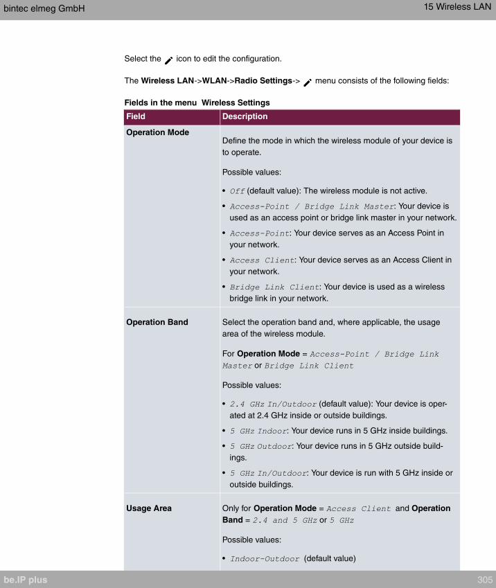
Select the icon to edit the configuration.
The Wireless LAN->WLAN->Radio Settings-> menu consists of the following fields:
Fields in the menu Wireless Settings
Field Description
Operation ModeDefine the mode in which the wireless module of your device is
to operate.
Possible values:
• (default value): The wireless module is not active.
• : Your device is
used as an access point or bridge link master in your network.
• : Your device serves as an Access Point in
your network.
• : Your device serves as an Access Client in
your network.
• : Your device is used as a wireless
bridge link in your network.
Operation Band Select the operation band and, where applicable, the usage
area of the wireless module.
For Operation Mode =
or
Possible values:
• (default value): Your device is oper-
ated at 2.4 GHz inside or outside buildings.
• : Your device runs in 5 GHz inside buildings.
• : Your device runs in 5 GHz outside build-
ings.
• : Your device is run with 5 GHz inside or
outside buildings.
Usage Area Only for Operation Mode = and Operation
Band = or
Possible values:
• (default value)
bintec elmeg GmbH 15 Wireless LAN
be.IP plus 305

Field Description
•
•
Channel The number of channels you can select depends on the country
setting. Please consult the data sheet for your device.
Access Point Mode / Bridge Mode:
Configuring the network name (SSID) in Access Point mode
means that wireless networks can be logically separated from
each other, but they can still physically interfere with each other
if they are operating on the same or closely adjacent wireless
channels. So if you are operating two or more radio networks
close to each other, it is advisable to allocate the networks to
different channels. Each of these should be spaced at least four
channels apart, as a network also partially occupies the adja-
cent channels.
In the case of manual channel selection, please make sure first
that the clients actually support these channels.
Possible values:
• For Operation Band =
Possible values are to and (default value).
is not possible in bridge mode.
• For Operation Band =
Possible values are , , , and (standard
value)
• For Operation Band = and
Only the option is possible here.
Access Client Mode:
In the Access Client Mode no channel you can select. The used
channel is shown.
Selected Channel Displays the channel used.
Used Secondary Chan- Not for Operation Mode =
15 Wireless LAN bintec elmeg GmbH
306 be.IP plus
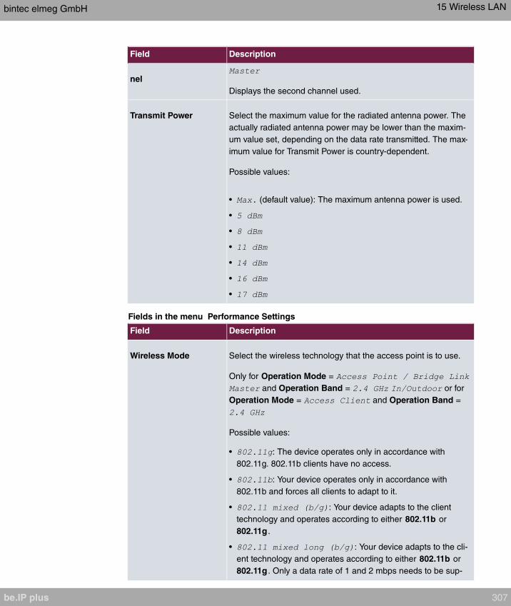
Field Description
nel
Displays the second channel used.
Transmit Power Select the maximum value for the radiated antenna power. The
actually radiated antenna power may be lower than the maxim-
um value set, depending on the data rate transmitted. The max-
imum value for Transmit Power is country-dependent.
Possible values:
• (default value): The maximum antenna power is used.
•
•
•
•
•
•
Fields in the menu Performance Settings
Field Description
Wireless Mode Select the wireless technology that the access point is to use.
Only for Operation Mode =
and Operation Band = or for
Operation Mode = and Operation Band =
Possible values:
• : The device operates only in accordance with
802.11g. 802.11b clients have no access.
• : Your device operates only in accordance with
802.11b and forces all clients to adapt to it.
• : Your device adapts to the client
technology and operates according to either 802.11b or
802.11g .
• : Your device adapts to the cli-
ent technology and operates according to either 802.11b or
802.11g . Only a data rate of 1 and 2 mbps needs to be sup-
bintec elmeg GmbH 15 Wireless LAN
be.IP plus 307

Field Description
ported by all clients (basic rates). This mode is also needed
for Centrino clients if connection problems occur.
• : Your device adapts to the
client technology and operates according to either 802.11b or
802.11g . The following applies for mixed-short: The data rates
5.5 and 11 mbps must be supported by all clients (basic
rates).
• : Your device operates according to either
802.11b, 802.11g or 802.11n.
• : Your device operates according to either
802.11g or 802.11n.
• : Your device operates only according to 802.11n.
For Operation Mode =
and and Operation Band =
, , and for
Operation Mode = and Operation Band =
Possible values:
• : The device operates only in accordance with
802.11a.
• : Your device operates only according to 802.11n.
• : Your device operates according to either
802.11a or 802.11n.
• : Your device operates according to
802.11ac, 802.11a or 802.11n.
• : Your device operates according to either
802.11ac or 802.11n.
Bandwidth For Operation Mode =
or
Not for Operation Band =
Select how many channels are to be used.
Possible values:
• (default value): One channel with 20 MHz bandwidth
is used.
15 Wireless LAN bintec elmeg GmbH
308 be.IP plus

Field Description
• : Two channels each with 20 MHz bandwidth are
used. In the case one channel acts as a control channels and
the other as an expansion channel.
• : In 802.11 ac mode, a bandwidth of 80 MHz is ad-
ditonally available.
Number of Spatial
Streams
Not for Wireless Mode =
Select how many traffic flows are to be used in parallel.
Possible values:
• : Two traffic flows are used.
• : One traffic flow is used.
Airtime fairness This function is not available for all devices.
The Airtime fairness function ensures that the access point's
send resources are distributed intelligently to the connected cli-
ents. This means that a powerful client (e. g. a 802.11n client)
cannot achieve only a poor flow level, because a less powerful
client (e. g. a 802.11a client) is treated in the same way when
apportioning.
The function is enabled with .
The function is disabled by default.
This fuction is only applied to unprioritized frames of the WMM
Classe "Background".
The menu Advanced Settings consists of the following fields:
Fields in the Advanced Settings menu for operating mode = Access Point / Bridge
Link Master
Field Description
Channel Plan Only for Operation Mode =
and Channel =
Select the desired channel plan.
The channel plan makes a preselection when a channel is se-
lected. This ensures that no channels overlap, i.e. a distance of
four channels is maintained between the channels used. This is
bintec elmeg GmbH 15 Wireless LAN
be.IP plus 309
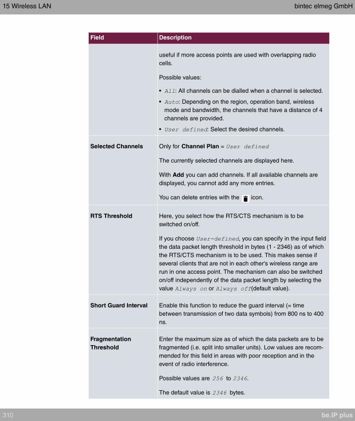
Field Description
useful if more access points are used with overlapping radio
cells.
Possible values:
• : All channels can be dialled when a channel is selected.
• : Depending on the region, operation band, wireless
mode and bandwidth, the channels that have a distance of 4
channels are provided.
• : Select the desired channels.
Selected Channels Only for Channel Plan =
The currently selected channels are displayed here.
With Add you can add channels. If all available channels are
displayed, you cannot add any more entries.
You can delete entries with the icon.
RTS Threshold Here, you select how the RTS/CTS mechanism is to be
switched on/off.
If you choose , you can specify in the input field
the data packet length threshold in bytes (1 - 2346) as of which
the RTS/CTS mechanism is to be used. This makes sense if
several clients that are not in each other's wireless range are
run in one access point. The mechanism can also be switched
on/off independently of the data packet length by selecting the
value or (default value).
Short Guard Interval Enable this function to reduce the guard interval (= time
between transmission of two data symbols) from 800 ns to 400
ns.
Fragmentation
Threshold
Enter the maximum size as of which the data packets are to be
fragmented (i.e. split into smaller units). Low values are recom-
mended for this field in areas with poor reception and in the
event of radio interference.
Possible values are to .
The default value is bytes.
15 Wireless LAN bintec elmeg GmbH
310 be.IP plus

If is selected for Operation Mode, the following parameters are
additionally available under Advanced Settings :
Fields in the menu Advanced Settings for Access Client Mode.
Field Description
Scan channels Choose the channels which the WLAN client automatically
scans for available wireless networks.
Possible values:
• (default value): All channels are scanned.
• : The channel is automatically selected.
• : The desired channels can therefore be
defined.
User Defined Channel
Plan
Only for Scan channels =
Define the channels which the WLAN client automatically scans
for available wireless networks.
Roaming Profile Select the roaming profile. The options available include typical
roaming functions.
Possible values:
• : The WLAN client searches for available
wireless networks as soon as the radio signal of the existing
radio connection becomes unsuitable for higher data rates.
• (default value): Standard roaming.
• : The WLAN client searches for available
wireless networks as soon as the radio signal of the existing
radio connection becomes weaker.
• : The WLAN client searches for available wire-
less networks if it is no longer connected to a wireless net-
work.
• : Specify the individual roaming paramet-
ers.
Scan ThresholdIndicates the value in dBm above which the system scans for
available wireless networks in the background.
The value can only be modified for Roaming Profile =
. The default value is .
bintec elmeg GmbH 15 Wireless LAN
be.IP plus 311

Field Description
Scan Interval Indicates the interval in milliseconds after which the system
scans for available wireless networks.
The value can only be modified for Roaming Profile =
. The default value is .
Min. Period Active
Scan Displays the minimum active scanning time for a frequency in
milliseconds.
The value can only be modified for Roaming Profile =
. The default value is .
Max. Period Active
Scan Displays the maximum active scanning time for a frequency in
milliseconds.
The value can only be modified for Roaming Profile =
. The default value is .
Min. Period Passive
Scan Displays the minimum passive scanning time for a frequency in
milliseconds.
The value can only be modified for Roaming Profile =
. The default value is .
Max. Period Passive
Scan Displays the maximum passive scanning time for a frequency in
milliseconds.
The value can only be modified for Roaming Profile =
. The default value is .
Max. Scan Duration Displays the maximum scanning duration for a frequency in mil-
liseconds.
The value can only be modified for Roaming Profile =
. The default value is .
15 Wireless LAN bintec elmeg GmbH
312 be.IP plus
15.1.2 Wireless Networks (VSS)
If you are operating your device in Access Point Mode ( Wireless LAN->WLAN->Radio
Settings-> ->Operation Mode = ), in the
menu Wireless LAN->WLAN->Wireless Networks (VSS)-> / New you can edit the
wireless networks required or set new ones up.
Note
The preset wireless network default has the following security settings in the ex works
state:
• Security Mode =
• WPA Mode =
• WPA Cipher as well as WPA2 Cipher =
• The Preshared Key is filled with an internal system value, which you must change
during configuration.
Setting network names
In contrast to a LAN set up over Ethernet, a wireless LAN does not have any cables for set-
ting up a permanent connection between the server and clients. Access violations or faults
may therefore occur with directly adjacent radio networks. To prevent this, every radio net-
work has a parameter that uniquely identifies the network and is comparable with a domain
name. Only clients with a network configuration that matches that of your device can com-
municate in this WLAN. The corresponding parameter is called the network name. In the
network environment, it is sometimes also referred to as the SSID.
Protection of wireless networks
As data can be transmitted over the air in the WLAN, this data can in theory be intercepted
and read by any attacker with the appropriate resources. Particular attention must therefore
be paid to protecting the wireless connection.
There are three security modes, WEP, WPA-PSK and WPA Enterprise. WPA Enterprise of-
fers the highest level of security, but this security mode is only really suitable for compan-
ies, because it requires a central authentication server. Private users should choose WEP
or preferably WPA-PSK with higher security as their security mode.
WEP
bintec elmeg GmbH 15 Wireless LAN
be.IP plus 313

802.11 defines the security standard WEP (Wired Equivalent Privacy = encryption of data
with 40 bit (Security Mode = ) or 104 bit (Security Mode = ). However,
this widely used WEP has proven susceptible to failure. However, a higher degree of se-
curity can only be achieved through hardware-based encryption which required additional
configuration (for example 3DES or AES). This permits even sensitive data from being
transferred via a radio path without fear of it being stolen.
IEEE 802.11i
Standard IEEE 802.11i for wireless systems contains basic security specifications for wire-
less networks, in particular with regard to encryption. It replaces the insecure WEP (Wired
Equivalent Privacy) with WPA (Wi-Fi Protected Access). It also includes the use of the ad-
vanced encryption standard (AES) to encrypt data.
WPA
WPA (Wi-Fi Protected Access) offers additional privacy by means of dynamic keys based
on the Temporal Key Integrity Protocol (TKIP), and offers PSK (preshared keys) or Extens-
ible Authentication Protocol (EAP) via 802.1x (e.g. RADIUS) for user authentication.
Authentication using EAP is usually used in large wireless LAN installations, as an authen-
tication instance in the form of a server (e.g. a RADIUS server) is used in these cases. PSK
(preshared keys) are usually used in smaller networks, such as those seen in SoHo (Small
office, Home office). Therefore, all the wireless LAN subscribers must know the PSK, be-
cause it is used to generate the session key.
WPA 2
The enhancement of WPA is WPA 2 . In WPA 2 , the 802.11i standard is not only imple-
mented for the first time in full, but another encryption algorithm AES (Advanced Encryption
Standard) is also used.
Access control
You can control which clients can access your wireless LAN via your device by creating an
Access Control List (Access Control oder MAC-Filter). In the Access Control List, you
enter the MAC addresses of the clients that may access your wireless LAN. All other clients
have no access.
Security measures
To protect the data transferred over the WLAN, the following configuration steps should be
carried out in the Wireless LAN->WLAN->Wireless Networks (VSS)->New menu, where
necessary:
15 Wireless LAN bintec elmeg GmbH
314 be.IP plus

• Change the access passwords for your device.
• Change the default SSID, Network Name (SSID) = , of your access point. Set
Visible = . This will exclude all WLAN clients that attempt to establish a connec-
tion with the general value for Network Name (SSID) and do not know the SSID set-
tings.
• Use the available encryption methods. To do this, select Security Mode = ,
, or and enter the relevant key in the access point un-
der WEP Key 1 - 4 or Preshared Key and in the WLAN clients.
• The WEP key should be changed regularly. To do this, change the Transmit Key . Select
the longer 104 Bit WEP key.
• For transmission of information with very high security relevance, configure Security
Mode = with WPA Mode = . This method contains hardware-
based encryption and RADIUS authentication of the client. In special cases, combination
with IPSec is possible.
• Restrict WLAN access to permitted clients. Enter the MAC addresses of the wireless net-
work cards for these clients in the Allowed Addresses list in the MAC-Filter menu (see
Fields in the menu MAC-Filter on page 319).
A list of all WLAN networks is displayed in the Wireless LAN->WLAN->Wireless Net-
works (VSS) menu.
15.1.2.1 Edit or New
Choose the icon to edit existing entries. Choose the New button to configure additional
wireless networks.
The Wireless LAN->WLAN->Wireless Networks (VSS)-> ->New menu consists of the
following fields:
Fields in the menu Service Set Parameters
Field Description
Network Name (SSID) Enter the name of the wireless network (SSID).
Enter an ASCII string with a maximum of 32 characters.
Also select whether the Network Name (SSID) is to be trans-
mitted.
The network name is displayed by selecting .
It is visible by default.
Intra-cell Repeating Select whether communication between the WLAN clients is to
bintec elmeg GmbH 15 Wireless LAN
be.IP plus 315
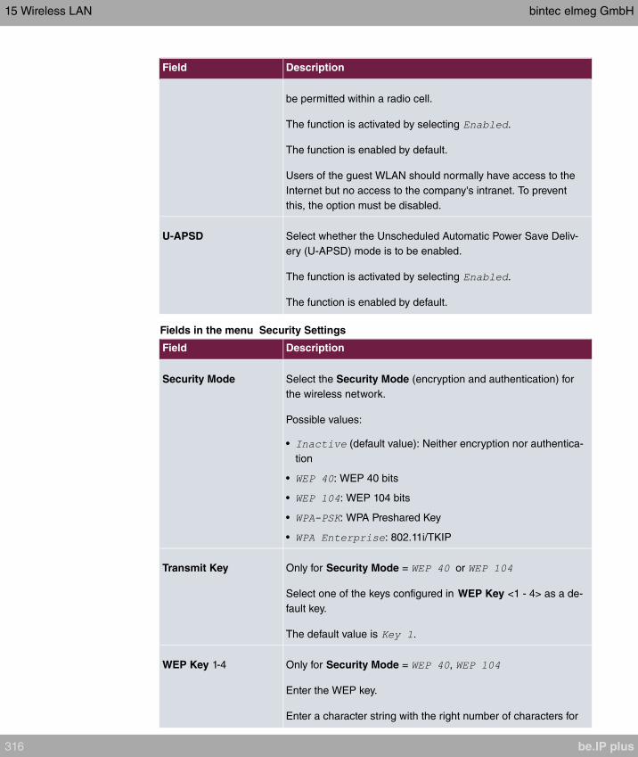
Field Description
be permitted within a radio cell.
The function is activated by selecting .
The function is enabled by default.
Users of the guest WLAN should normally have access to the
Internet but no access to the company's intranet. To prevent
this, the option must be disabled.
U-APSD Select whether the Unscheduled Automatic Power Save Deliv-
ery (U-APSD) mode is to be enabled.
The function is activated by selecting .
The function is enabled by default.
Fields in the menu Security Settings
Field Description
Security Mode Select the Security Mode (encryption and authentication) for
the wireless network.
Possible values:
• (default value): Neither encryption nor authentica-
tion
• : WEP 40 bits
• : WEP 104 bits
• : WPA Preshared Key
• : 802.11i/TKIP
Transmit Key Only for Security Mode = or
Select one of the keys configured in WEP Key <1 - 4> as a de-
fault key.
The default value is .
WEP Key 1-4 Only for Security Mode = ,
Enter the WEP key.
Enter a character string with the right number of characters for
15 Wireless LAN bintec elmeg GmbH
316 be.IP plus
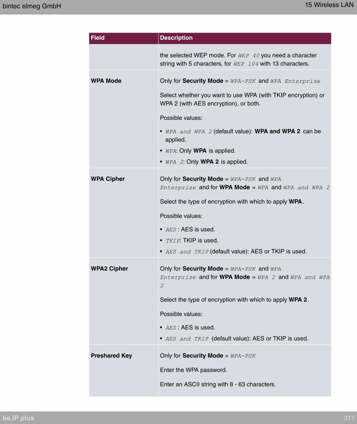
Field Description
the selected WEP mode. For you need a character
string with 5 characters, for with 13 characters.
WPA Mode Only for Security Mode = and
Select whether you want to use WPA (with TKIP encryption) or
WPA 2 (with AES encryption), or both.
Possible values:
• (default value): WPA and WPA 2 can be
applied.
• : Only WPA is applied.
• : Only WPA 2 is applied.
WPA Cipher Only for Security Mode = and
and for WPA Mode = and
Select the type of encryption with which to apply WPA .
Possible values:
• : AES is used.
• : TKIP is used.
• (default value): AES or TKIP is used.
WPA2 Cipher Only for Security Mode = and
and for WPA Mode = and
Select the type of encryption with which to apply WPA 2 .
Possible values:
• : AES is used.
• (default value): AES or TKIP is used.
Preshared Key Only for Security Mode =
Enter the WPA password.
Enter an ASCII string with 8 - 63 characters.
bintec elmeg GmbH 15 Wireless LAN
be.IP plus 317
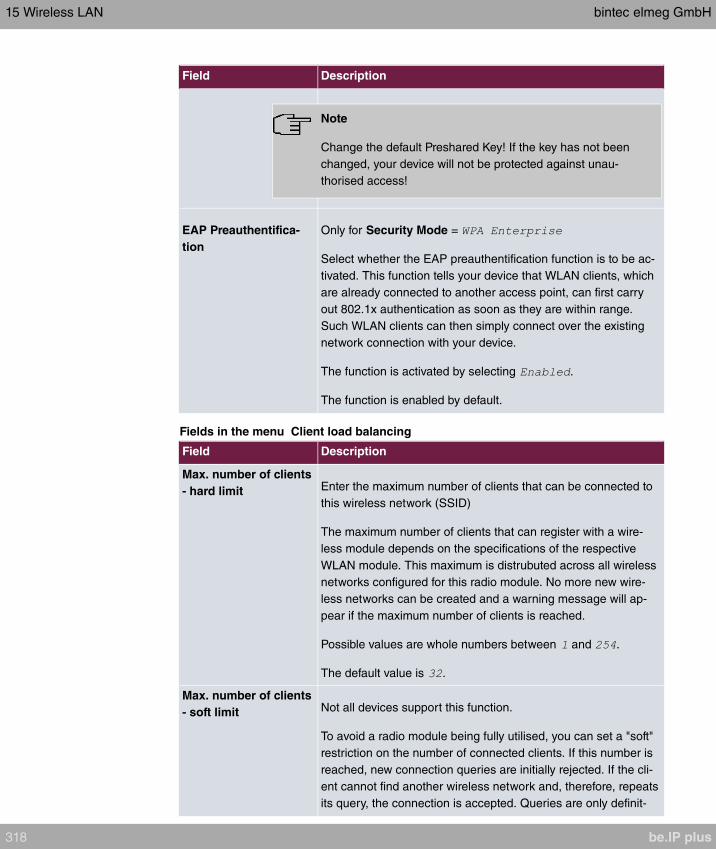
Field Description
Note
Change the default Preshared Key! If the key has not been
changed, your device will not be protected against unau-
thorised access!
EAP Preauthentifica-
tion
Only for Security Mode =
Select whether the EAP preauthentification function is to be ac-
tivated. This function tells your device that WLAN clients, which
are already connected to another access point, can first carry
out 802.1x authentication as soon as they are within range.
Such WLAN clients can then simply connect over the existing
network connection with your device.
The function is activated by selecting .
The function is enabled by default.
Fields in the menu Client load balancing
Field Description
Max. number of clients
- hard limit Enter the maximum number of clients that can be connected to
this wireless network (SSID)
The maximum number of clients that can register with a wire-
less module depends on the specifications of the respective
WLAN module. This maximum is distrubuted across all wireless
networks configured for this radio module. No more new wire-
less networks can be created and a warning message will ap-
pear if the maximum number of clients is reached.
Possible values are whole numbers between and .
The default value is .
Max. number of clients
- soft limit Not all devices support this function.
To avoid a radio module being fully utilised, you can set a "soft"
restriction on the number of connected clients. If this number is
reached, new connection queries are initially rejected. If the cli-
ent cannot find another wireless network and, therefore, repeats
its query, the connection is accepted. Queries are only definit-
15 Wireless LAN bintec elmeg GmbH
318 be.IP plus
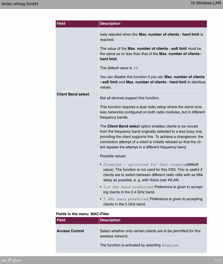
Field Description
ively rejected when the Max. number of clients - hard limit is
reached.
The value of the Max. number of clients - soft limit must be
the same as or less than that of the Max. number of clients -
hard limit.
The default value is .
You can disable this function if you set Max. number of clients
- soft limit and Max. number of clients - hard limit to identical
values.
Client Band selectNot all devices support this function.
This function requires a dual radio setup where the same wire-
less networkis configured on both radio modules, but in different
frequency bands.
The Client Band select option enables clients to be moved
from the frequency band originally selected to a less busy one,
providing the client supports this. To achieve a changeover, the
connection attempt of a client is initially refused so that the cli-
ent repeats the attempt in a different frequency band.
Possible values:
• (default
value): The function is not used for this VSS. This is useful if
clients are to switch between different radio cells with as little
delay as possible, e. g. with Voice over WLAN.
• : Preference is given to accept-
ing clients in the 2.4 GHz band.
• : Preference is given to accepting
clients in the 5 GHz band.
Fields in the menu MAC-Filter
Field Description
Access Control Select whether only certain clients are to be permitted for this
wireless network.
The function is activated by selecting .
bintec elmeg GmbH 15 Wireless LAN
be.IP plus 319

Field Description
The function is disabled by default.
Allowed Addresses Use Add to make entries and enter the MAC addresses (MAC
Address) of the clients to be permitted.
Fields in the menu Bandwidth limitation for each WLAN client
Field Description
Rx Shaping Select a bandwidth limitation in the receive direction.
Possible values are
• (default value)
• , , up to
in single Mbit/s steps, , , ,
and .
Tx Shaping Select a bandwidth limitation in the transmit direction.
Possible values are
• (default value)
• , , up to
in single Mbit/s steps, , , ,
and .
Fields in the menu Advanced Settings
Field Description
Beacon Period Enter the time in milliseconds between the sending of two
beacons.
This value is transmitted in Beacon and Probe Response
Frames.
Possible values are to .
The default value is ms.
DTIM Period Enter the interval for the Delivery Traffic Indication Message
(DTIM).
The DTIM field is a data field in transmitted beacons that in-
forms clients about the window to the next broadcast or multic-
ast transmission. If clients operate in power save mode, they
15 Wireless LAN bintec elmeg GmbH
320 be.IP plus
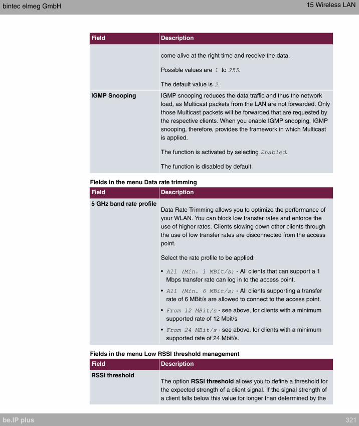
Field Description
come alive at the right time and receive the data.
Possible values are to .
The default value is .
IGMP Snooping IGMP snooping reduces the data traffic and thus the network
load, as Multicast packets from the LAN are not forwarded. Only
those Multicast packets will be forwarded that are requested by
the respective clients. When you enable IGMP snooping, IGMP
snooping, therefore, provides the framework in which Multicast
is applied.
The function is activated by selecting .
The function is disabled by default.
Fields in the menu Data rate trimming
Field Description
5 GHz band rate profileData Rate Trimming allows you to optimize the performance of
your WLAN. You can block low transfer rates and enforce the
use of higher rates. Clients slowing down other clients through
the use of low transfer rates are disconnected from the access
point.
Select the rate profile to be applied:
• - All clients that can support a 1
Mbps transfer rate can log in to the access point.
• - All clients supporting a transfer
rate of 6 MBit/s are allowed to connect to the access point.
• - see above, for clients with a minimum
supported rate of 12 Mbit/s
• - see above, for clients with a minimum
supported rate of 24 Mbit/s.
Fields in the menu Low RSSI threshold management
Field Description
RSSI thresholdThe option RSSI threshold allows you to define a threshold for
the expected strength of a client signal. If the signal strength of
a client falls below this value for longer than determined by the
bintec elmeg GmbH 15 Wireless LAN
be.IP plus 321
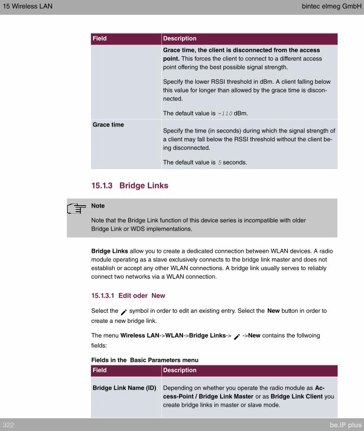
Field Description
Grace time, the client is disconnected from the access
point. This forces the client to connect to a different access
point offering the best possible signal strength.
Specify the lower RSSI threshold in dBm. A client falling below
this value for longer than allowed by the grace time is discon-
nected.
The default value is dBm.
Grace timeSpecify the time (in seconds) during which the signal strength of
a client may fall below the RSSI threshold without the client be-
ing disconnected.
The default value is seconds.
15.1.3 Bridge Links
Note
Note that the Bridge Link function of this device series is incompatible with older
Bridge Link or WDS implementations.
Bridge Links allow you to create a dedicated connection between WLAN devices. A radio
module operating as a slave exclusively connects to the bridge link master and does not
establish or accept any other WLAN connections. A bridge link usually serves to reliably
connect two networks via a WLAN connection.
15.1.3.1 Edit oder New
Select the symbol in order to edit an existing entry. Select the New button in order to
create a new bridge link.
The menu Wireless LAN->WLAN->Bridge Links-> ->New contains the follwoing
fields:
Fields in the Basic Parameters menu
Field Description
Bridge Link Name (ID) Depending on whether you operate the radio module as Ac-
cess-Point / Bridge Link Master or as Bridge Link Client you
create bridge links in master or slave mode.
15 Wireless LAN bintec elmeg GmbH
322 be.IP plus
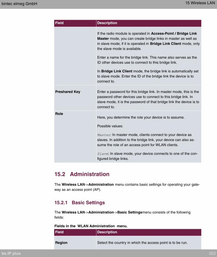
Field Description
If the radio module is operated in Access-Point / Bridge Link
Master mode, you can create bridge links in master as well as
in slave mode; if it is operated in Bridge Link Client mode, only
the slave mode is available.
Enter a name for the bridge link. This name also serves as the
ID other devices use to connect to this bridge link.
In Bridge Link Client mode, the bridge link is automatically set
to slave mode. Enter the ID of the bridge link the device is to
connect to.
Preshared Key Enter a password for this bridge link. In master mode, this is the
password other devices use to connect to this bridge link. In
slave mode, it is the password of that bridge link the device is to
connect to.
RoleHere, you determine the role your device is to assume.
Possible values:
: In master mode, clients connect to your device as
slaves. In addition to the bridge link, your device can also as-
sume the role of an access point for WLAN clients.
: In slave mode, your device connects to one of the con-
figured bridge links.
15.2 Administration
The Wireless LAN->Administration menu contains basic settings for operating your gate-
way as an access point (AP).
15.2.1 Basic Settings
The Wireless LAN->Administration->Basic Settingsmenu consists of the following
fields:
Fields in the WLAN Administration menu.
Field Description
Region Select the country in which the access point is to be run.
bintec elmeg GmbH 15 Wireless LAN
be.IP plus 323
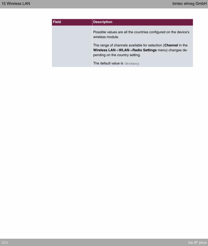
Field Description
Possible values are all the countries configured on the device's
wireless module.
The range of channels available for selection (Channel in the
Wireless LAN->WLAN->Radio Settings menu) changes de-
pending on the country setting.
The default value is .
15 Wireless LAN bintec elmeg GmbH
324 be.IP plus
Chapter 16 Wireless LAN Controller
By using the wireless LAN controller, you can set up and manage a WLAN infrastructure
with multiple access points (APs). The WLAN controller has a Wizard which assists you in
the configuration of your access points. The system uses the CAPWAP protocol (Control
and Provisioning of Wireless Access Points Protocol) for any communication between mas-
ters and slaves.
In smaller WLAN infrastructures with up to six APs, one of the AP's assumes the master
function and manages the other AP's as well as itself. In larger WLAN networks a gateway,
e.g. such as a bintec R1202, assumes the master function and manages the AP's.
Provided the controller has "located" all of the APs in its system, each of these shall re-
ceive a new passport and configuration in succession, i.e. they are managed via the WLAN
controller and can no longer be amended "externally".
With the WLAN controller you can
• automatically detect individual access points (APs) and connect to a WLAN network
• Load the system software into the APs
• Load the configuration into the APs
• Monitor and manage APs
Please refer to your gateway's data sheet to find out the number of APs that you can man-
age with your gateway's wireless LAN controller and details of the licenses required.
16.1 Wizard
The Wizard menu offers step-by-step instructions for the set up of a WLAN infrastructure.
The Wizard guides you through the configuration.
Note
We highly recommended that you use the Wizard when initially configuring your WLAN
infrastructure.
16.1.1 Wireless LAN Controller Wizard
Here you can configure all of the various settings that you require for the actual wireless
LAN controller.
bintec elmeg GmbH 16 Wireless LAN Controller
be.IP plus 325
16.1.1.1 Basic Settings
The wireless LAN controller uses the following settings:
Region
Select the country in which the wireless controller is to be operated.
Please note: The range of channels that can be used varies depending on the country set-
ting.
Interface
Select the interface to be used for the wireless controller.
DHCP Server
Select whether an external DHCP server shall assign IP addresses to the APs or if you
wish to assign fixed IP addresses yourself. Alternatively, you can use your device as a DH-
CP server. For this internal DHCP server, CAPWAP option 138 is active in order to allow
communication between the master and slaves.
If you use static IP addresses in your network, you must enter these to all APs manually.
The IP addresses of the wireless LAN controller must be entered for each AP in the Sys-
tem Management->Global Settings->System menu in the Manual WLAN Controller IP
Address field.
Please note: Make sure that option 138 is active when using an external DHCP server.
If you wish to use a bintec elmegbintec elmeg Gateway for example as a DHCP server,
click on the GUI menu for this device under Local Services->DHCP Server->DHCP Con-
figuration->New->Advanced Settings in the DHCP Options field on the Add button. Se-
lect as Option and in the Value field enter the IP address of the
WLAN controller.
IP Address Range
If the IP addresses are to be assigned internally, you must enter the start and end IP ad-
dress of the desired range.
Please note: If you click on Next, a warning appears which informs you that continuing will
overwrite the wireless LAN controller configuration. By clicking on OK you signal that you
agree with this and wish to continue with the configuration.
16 Wireless LAN Controller bintec elmeg GmbH
326 be.IP plus
16.1.1.2 Radio Profile
Select which frequency band your WLAN controller shall use.
If the is set then the 2.4 GHz frequency band is used.
If the is set then the 5 GHz frequency band is used.
If the corresponding device contains two wireless modules, you can Use two independent
radio profiles. This assigns to module 1 and
to module 2.
The function is activated by selecting .
The function is disabled by default.
16.1.1.3 Wireless Network
All of the configured wireless networks (VSS) are displayed in the list. At least one wireless
network (VSS) is set up. This entry cannot be deleted.
Click on to edit an existing entry.
You can also delete entries using the icon.
With Add, you can create new entries. You can create up to eight wireless networks (VSS)
for a wireless module.
Note
If you wish to use the default wireless network that is set up, you must at least change
the Preshared Key parameters. Otherwise you will be prompted.
16.1.1.3.1 Change or add wireless networks
Click on to edit an existing entry.
With Add, you can create new entries.
The following parameters are available
Network Name (SSID)
Enter the name of the wireless network (SSID).
bintec elmeg GmbH 16 Wireless LAN Controller
be.IP plus 327
Enter an ASCII string with a maximum of 32 characters.
Also select whether the Network Name (SSID) is to be transmitted.
IGMP Snooping
IGMP snooping reduces the data traffic and thus the network load.
The function is activated by selecting .
Security Mode
Select the security mode (encryption and authentication) for the wireless network.
Please note: means 802.11x.
WPA Mode
Select for Security Mode = or , whether you wish to use
WPA oder WPA 2 or both.
Preshared Key
Enter the WPA password for Security Mode = .
Enter an ASCII string with 8 - 63 characters.
Important
Change the default Preshared Key! If the key has not been changed, your device will
not be protected against unauthorised access!
Radius Server
You can control access to a wireless network via a RADIUS server.
With Add, you can create new entries.
Enter the IP address and the password of the desired RADIUS server.
EAP Preauthentification
For Security Mode = , select whether the EAP preauthentification func-
tion is to be . This function tells your device that WLAN clients, which are already
connected to another access point, can first carry out 802.1x authentication as soon as
they are within range. Such WLAN clients can then simply connect over the existing net-
work connection with your device.
16 Wireless LAN Controller bintec elmeg GmbH
328 be.IP plus
VLAN
Select whether the VLAN segmentation is to be used for this wireless network.
If you wish to use VLAN segmentation, enter a value between and in the input
field in order to identify the VLAN. (VLAN ID is not possible!).
Note
Before you continue, please ensure that all access points that the WLAN controller
shall manage are correctly wired and switched on.
16.1.1.4 Start automatic installation
You will see a list of all detected access points.
If you wish to change the settings of a detected AP, click on in the corresponding entry.
You will see the settings for all selected access points. You can change these settings.
The following parameters are available in the Access Point Settings menu:
Location
Displays the stated locality of the AP. You can enter another locality.
Assigned Wireless Network (VSS)
Displays the wireless networks that are currently assigned.
The following parameters are available in the wireless module 1 menu:
(The parts wireless module 1 and wireless module 2 are displayed if the AP has two wire-
less modules.)
Operation Mode
Select the mode in which the wireless module is to be operated.
Possible values:
• (default value): The wireless module is used as an access point in your network.
• : The wireless module is not active.
Active Radio Profile
bintec elmeg GmbH 16 Wireless LAN Controller
be.IP plus 329
Displays the wireless module profile that is currently selected. You can select another wire-
less module profile from the list if more than one wireless module profile are being set up.
Channel
Displays the channel that is assigned. You can select an alternative channel.
The number of channels you can select depends on the country setting. Please consult the
data sheet for your device.
Note
Configuring the network name (SSID) in Access Point mode means that wireless net-
works can be logically separated from each other, but they can still physically interfere
with each other if they are operating on the same or closely adjacent wireless chan-
nels. So if you are operating two or more radio networks close to each other, it is ad-
visable to allocate the networks to different channels. Each of these should be spaced
at least four channels apart, as a network also partially occupies the adjacent chan-
nels.
In the case of manual channel selection, please make sure first that the APs actually sup-
port these channels.
Transmit Power
Displays the transmission power in dBm. You can select another transmission power.
With OK you apply the settings.
Select the access points that your WLAN controller shall manage. In the Manage column,
click on the desired entries or click on Select all in order to select all entries. Click the
Deselect all button to disable all entries and to then select individual entries if required
(e.g. for large lists).
Click on Start in order to install the WLAN and automatically assign the frequencies.
Note
If there are not enough licences available, the message "The maximum number of
slave access points that can be supported has been exceeded". Please check your li-
cences. If this message is displayed then you should obtain additional licences if ap-
propriate.
During the installation of the WLAN and the allocation of frequencies, on the messages dis-
16 Wireless LAN Controller bintec elmeg GmbH
330 be.IP plus

played you will see how far the installation has progressed. The display is continuously up-
dated.
Provided that non-overlapping wireless channels are located for all access points, the con-
figuration that is set in the Wizard is transferred to the access points.
When the installation is complete, you will see a list of the Managed access points.
Under Configure the Alert Service for WLAN surveillance, click Start to monitor your
managed APs. You are taken to the External Reporting->Alert Service->Alert Recipient
menu with the default setting Event = . You can specify that you
wish to be notified by e-mail if the event occurs.
Click under New Neighborscan on Start, to rescan adjacent AP's. You will receive a warn-
ing that the wireless modules of the access points must also be disabled for a certain peri-
od of time. When you start the process with OK, a progress bar is displayed. The located
AP display is updated every ten seconds.
16.1.2 Wireless LAN Controller VLAN Configuration
In order to separate WLANs (VSS) from each other, you can activate the VLAN function
and assign a VLAN ID during the configuration of a VSS. For the separation from other in-
terfaces to work properly, you need to create a virtual interface with its own IP configura-
tion, and, if applicable, a corresponding DHCP pool which provides IP addresses to clients
connecting to this VLAN. You can make this settings - as usual - in the menus LAN->IP
Configuration and Local Services->DHCP Server, correspondingly; or you make use of
the menu offered here. All settings you make here are automatically transferred to the other
menus, as well.
You are shown an overview of VLANs that have already been created with their VLAN IDs
and their corresponding IP and DHCP configuration. In order to edit an entry, select the
icon in the respective line. To create a new entry, select New. A new entry can only be cre-
ated for a VSS with a VLAN ID that does not yet have a VLAN configuration.
16.1.2.1 Edit or Neu
Select the symbol in order to edit an existing entry. Select the New button in order to
create additional VLANs.
The menu Wireless LAN Controller->Wizard->Wireless LAN Controller VLAN Config-
uration->New consists of the following fields:
Fields in the menu VSS VLAN Network Configuration
bintec elmeg GmbH 16 Wireless LAN Controller
be.IP plus 331

Field Dsecription
VLAN ID Select an existing VLAN from the pull down menu. Only those
IDs without a configuration are offered.
IP Address/Netmask Specify the IP configuration of the new interface. Make sure that
the address has not been used before.
DHCP Server In order to provide clients connecting to this VLAN with an IP
configuration, you can either use an external DHCP server, or
you can use the integrated one of your device.
Possiblöe values:
• : Select this option if you are already
operating a DHCP server in you netweork, tor if clients con-
necting to this VLAN have a static IP configuration. Make sure
that an external DHCP server can be reached from the VLAN.
• : Select this option if you intend to use your device
as DHCP server for this VLAN.
IP Address Range Only for DHCP Server =
Specify the first and the last IP address which your device is to
distribute inside the VLAN. Make sure that the address range
corresponds to the IP address of the interface for this VLAN,
and that it does not overlap with other IP address pools.
The DHCP configuration automatically assumes your device to
be the gateway. The lease time is 120 minutes. If you want to
adjust these settings, go the the menu Local Services->DHCP
Server->DHCP Configuration.
16.2 Controller Configuration
In this menu, you make the basic settings for the wireless LAN controller.
16.2.1 General
The Wireless LAN Controller->Controller Configuration->General menu consists of the
following fields:
Fields in the Basic Settings menu.
16 Wireless LAN Controller bintec elmeg GmbH
332 be.IP plus
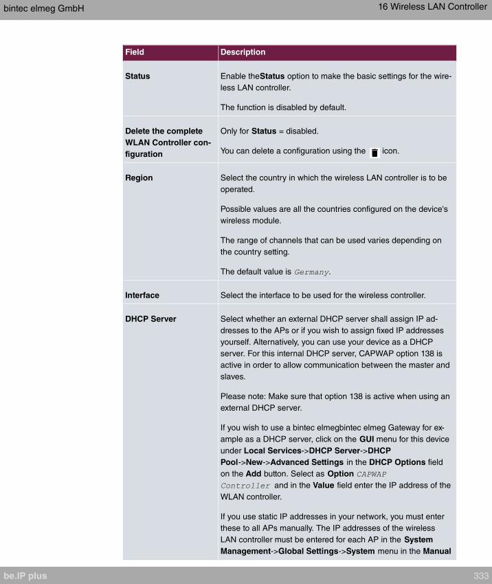
Field Description
Status Enable theStatus option to make the basic settings for the wire-
less LAN controller.
The function is disabled by default.
Delete the complete
WLAN Controller con-
figuration
Only for Status = disabled.
You can delete a configuration using the icon.
Region Select the country in which the wireless LAN controller is to be
operated.
Possible values are all the countries configured on the device's
wireless module.
The range of channels that can be used varies depending on
the country setting.
The default value is .
Interface Select the interface to be used for the wireless controller.
DHCP Server Select whether an external DHCP server shall assign IP ad-
dresses to the APs or if you wish to assign fixed IP addresses
yourself. Alternatively, you can use your device as a DHCP
server. For this internal DHCP server, CAPWAP option 138 is
active in order to allow communication between the master and
slaves.
Please note: Make sure that option 138 is active when using an
external DHCP server.
If you wish to use a bintec elmegbintec elmeg Gateway for ex-
ample as a DHCP server, click on the GUI menu for this device
under Local Services->DHCP Server->DHCP
Pool->New->Advanced Settings in the DHCP Options field
on the Add button. Select as Option
and in the Value field enter the IP address of the
WLAN controller.
If you use static IP addresses in your network, you must enter
these to all APs manually. The IP addresses of the wireless
LAN controller must be entered for each AP in the System
Management->Global Settings->System menu in the Manual
bintec elmeg GmbH 16 Wireless LAN Controller
be.IP plus 333
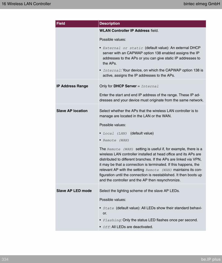
Field Description
WLAN Controller IP Address field.
Possible values:
• (default value): An external DHCP
server with an CAPWAP option 138 enabled assigns the IP
addresses to the APs or you can give static IP addresses to
the APs.
• : Your device, on which the CAPWAP option 138 is
active, assigns the IP addresses to the APs.
IP Address Range Only for DHCP Server =
Enter the start and end IP address of the range. These IP ad-
dresses and your device must originate from the same network.
Slave AP location Select whether the APs that the wireless LAN controller is to
manage are located in the LAN or the WAN.
Possible values:
• (default value)
•
The setting is useful if, for example, there is a
wireless LAN controller installed at head office and its APs are
distributed to different branches. If the APs are linked via VPN,
it may be that a connection is terminated. If this happens, the
relevant AP with the setting maintains its con-
figuration until the connection is reestablished. It then boots up
and the controller and the AP then resynchronize.
Slave AP LED mode Select the lighting scheme of the slave AP LEDs.
Possible values:
• (default value): All LEDs show their standard behavi-
or.
• : Only the status LED flashes once per second.
• : All LEDs are deactivated.
16 Wireless LAN Controller bintec elmeg GmbH
334 be.IP plus

16.2.2 Slave AP Autoprofile
The Wireless LAN Controller offers the option of automatically including and configuring an
access point that is being integrated into the network accessible by the WLAN Controller. In
order to be able to automatically assign a configuration to a new access point you have to
configure a profile that is valid for all new access points that match certain criteria.
16.2.2.1 Edit or New
The Wireless LAN Controller->Controller Configuration->Slave AP Autoprofile ->New
menu consists of the following fields:
Fields in the Access Point Filter menu
Field Description
MAC AddressEnter the MAC address of an access point that is to be con-
figured automatically when it is integrated into the network.
By default, All is activated so that the entry matches every new
access point.
IP Address / Netmask Enter an IP address and a netmask. You can enter host as well
as network addresses so that you can filter for individual access
points as well as for groups of access points from a specific
subnet.
Fields in the Access Point Settings menu
Field Description
Location Specify the location of the AP.
Description Enter a unique description for the AP.
Fields in the Radio 1 or in the Radio 2
Field Description
Operating ModeWählen Sie aus, ob der Betriebsmodus vom verwendeten Funk-
modulprofil bestimmt werden soll.
The function is activated by selecting .
The function is enabled by default.
Active Radio ProfileOnly for Operating Mode =
Select a radio profile.
Possible values:
bintec elmeg GmbH 16 Wireless LAN Controller
be.IP plus 335
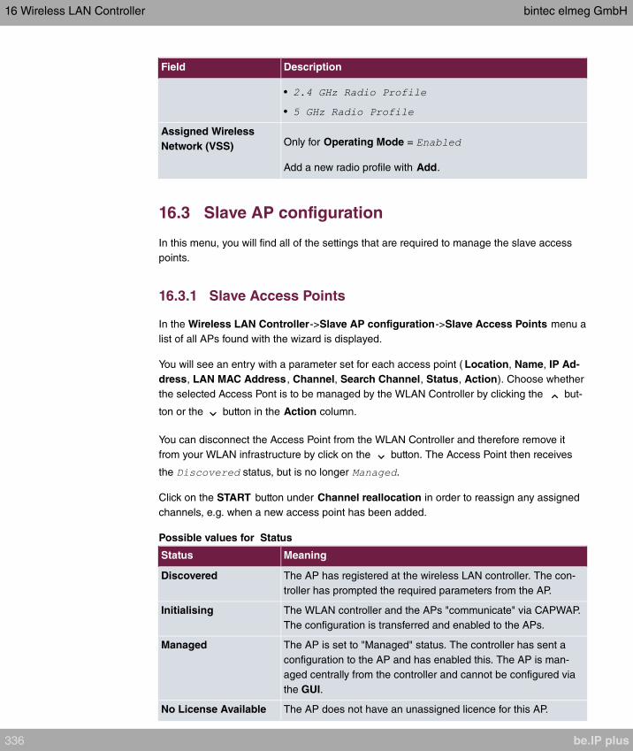
Field Description
•
•
Assigned Wireless
Network (VSS) Only for Operating Mode =
Add a new radio profile with Add.
16.3 Slave AP configuration
In this menu, you will find all of the settings that are required to manage the slave access
points.
16.3.1 Slave Access Points
In the Wireless LAN Controller->Slave AP configuration->Slave Access Points menu a
list of all APs found with the wizard is displayed.
You will see an entry with a parameter set for each access point ( Location, Name, IP Ad-
dress, LAN MAC Address , Channel, Search Channel, Status, Action). Choose whether
the selected Access Pont is to be managed by the WLAN Controller by clicking the but-
ton or the button in the Action column.
You can disconnect the Access Point from the WLAN Controller and therefore remove it
from your WLAN infrastructure by click on the button. The Access Point then receives
the status, but is no longer .
Click on the START button under Channel reallocation in order to reassign any assigned
channels, e.g. when a new access point has been added.
Possible values for Status
Status Meaning
Discovered The AP has registered at the wireless LAN controller. The con-
troller has prompted the required parameters from the AP.
Initialising The WLAN controller and the APs "communicate" via CAPWAP.
The configuration is transferred and enabled to the APs.
Managed The AP is set to "Managed" status. The controller has sent a
configuration to the AP and has enabled this. The AP is man-
aged centrally from the controller and cannot be configured via
the GUI.
No License Available The AP does not have an unassigned licence for this AP.
16 Wireless LAN Controller bintec elmeg GmbH
336 be.IP plus
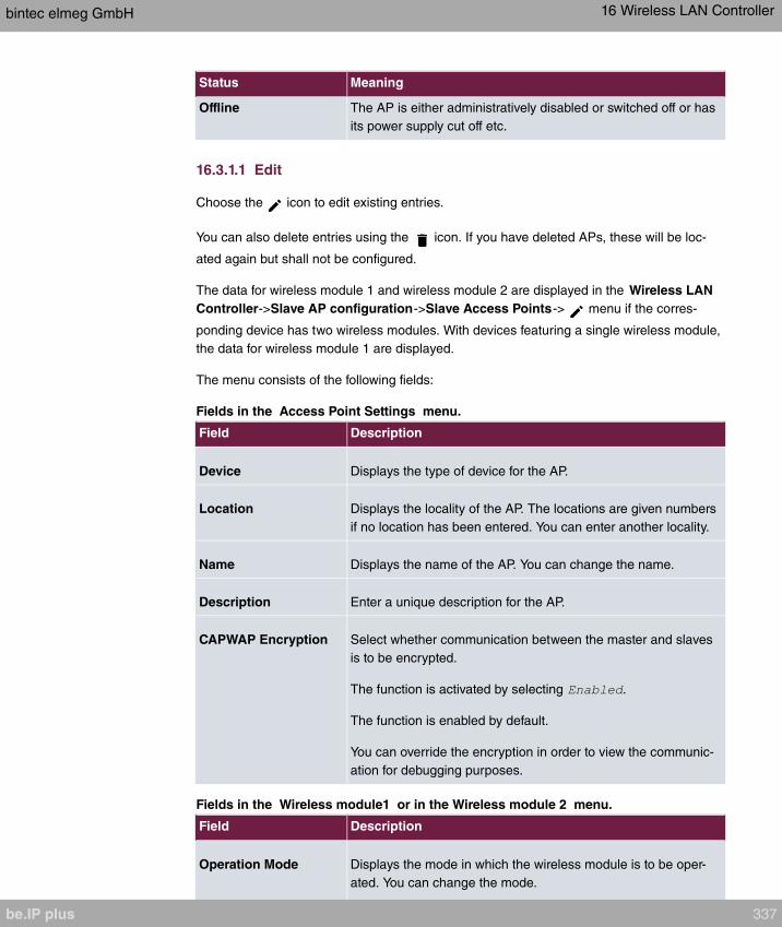
Status Meaning
Offline The AP is either administratively disabled or switched off or has
its power supply cut off etc.
16.3.1.1 Edit
Choose the icon to edit existing entries.
You can also delete entries using the icon. If you have deleted APs, these will be loc-
ated again but shall not be configured.
The data for wireless module 1 and wireless module 2 are displayed in the Wireless LAN
Controller->Slave AP configuration->Slave Access Points-> menu if the corres-
ponding device has two wireless modules. With devices featuring a single wireless module,
the data for wireless module 1 are displayed.
The menu consists of the following fields:
Fields in the Access Point Settings menu.
Field Description
Device Displays the type of device for the AP.
Location Displays the locality of the AP. The locations are given numbers
if no location has been entered. You can enter another locality.
Name Displays the name of the AP. You can change the name.
Description Enter a unique description for the AP.
CAPWAP Encryption Select whether communication between the master and slaves
is to be encrypted.
The function is activated by selecting .
The function is enabled by default.
You can override the encryption in order to view the communic-
ation for debugging purposes.
Fields in the Wireless module1 or in the Wireless module 2 menu.
Field Description
Operation Mode Displays the mode in which the wireless module is to be oper-
ated. You can change the mode.
bintec elmeg GmbH 16 Wireless LAN Controller
be.IP plus 337
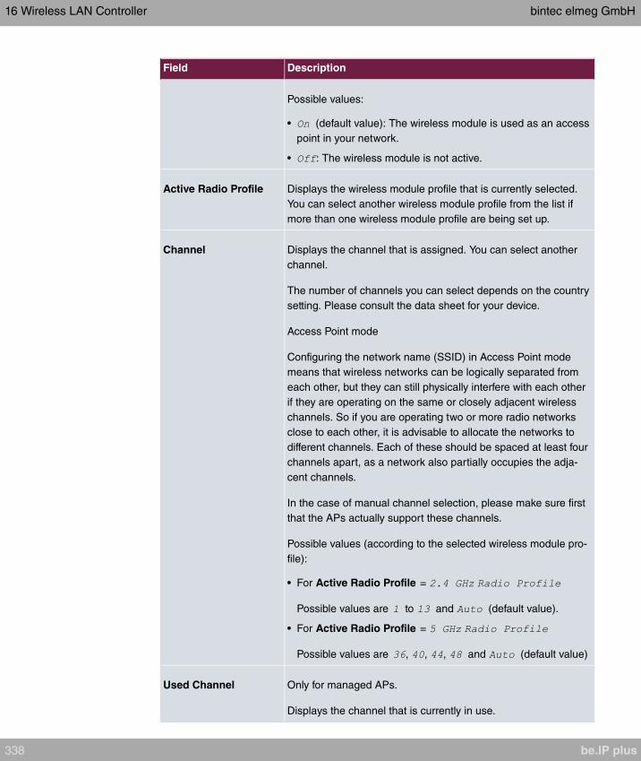
Field Description
Possible values:
• (default value): The wireless module is used as an access
point in your network.
• : The wireless module is not active.
Active Radio Profile Displays the wireless module profile that is currently selected.
You can select another wireless module profile from the list if
more than one wireless module profile are being set up.
Channel Displays the channel that is assigned. You can select another
channel.
The number of channels you can select depends on the country
setting. Please consult the data sheet for your device.
Access Point mode
Configuring the network name (SSID) in Access Point mode
means that wireless networks can be logically separated from
each other, but they can still physically interfere with each other
if they are operating on the same or closely adjacent wireless
channels. So if you are operating two or more radio networks
close to each other, it is advisable to allocate the networks to
different channels. Each of these should be spaced at least four
channels apart, as a network also partially occupies the adja-
cent channels.
In the case of manual channel selection, please make sure first
that the APs actually support these channels.
Possible values (according to the selected wireless module pro-
file):
• For Active Radio Profile =
Possible values are to and (default value).
• For Active Radio Profile =
Possible values are , , , and (default value)
Used Channel Only for managed APs.
Displays the channel that is currently in use.
16 Wireless LAN Controller bintec elmeg GmbH
338 be.IP plus

Field Description
Transmit Power Displays the transmission power. You can select another trans-
mission power.
Possible values:
• (default value): The maximum antenna power is used.
•
•
•
•
•
•
Assigned Wireless
Network (VSS)
Displays the wireless networks that are currently assigned.
16.3.2 Radio Profiles
An overview of all created wireless module profiles is displayed in the Wireless LAN Con-
troller->Slave AP configuration->Radio Profiles menu. A profile with 2.4 GHz and a pro-
file with 5 GHz are created by default; the 2.4 GHz profile cannot be deleted.
For each wireless module profile you will see an entry with a parameter set (Radio
Profiles, Configured Radio Modules, Operation Band, Wireless Mode).
16.3.2.1 Edit or New
Choose the icon to edit existing entries. Select the New button in order to create new
wireless module profiles.
The Wireless LAN Controller->Slave AP configuration->Radio Profiles-> / New
menu consists of the following fields:
Fields in the menu Radio Profile Definition
Field Description
DescriptionEnter the desired description of the wireless module profile.
Operation ModeDefine the mode in which the wireless module profile is to be
operated.
bintec elmeg GmbH 16 Wireless LAN Controller
be.IP plus 339
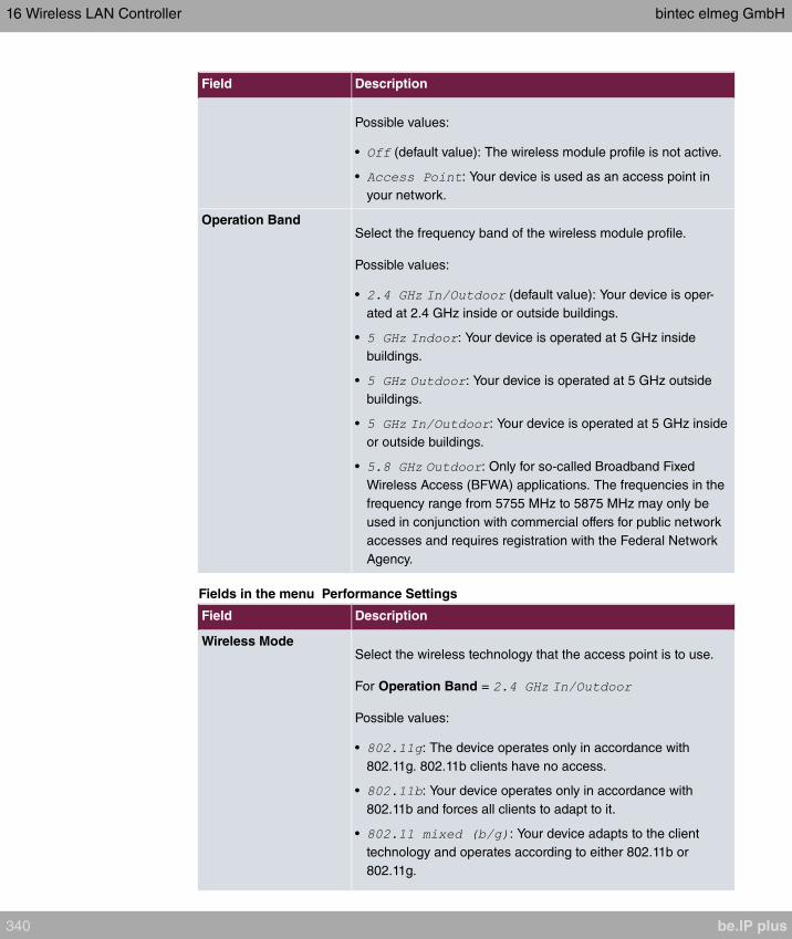
Field Description
Possible values:
• (default value): The wireless module profile is not active.
• : Your device is used as an access point in
your network.
Operation BandSelect the frequency band of the wireless module profile.
Possible values:
• (default value): Your device is oper-
ated at 2.4 GHz inside or outside buildings.
• : Your device is operated at 5 GHz inside
buildings.
• : Your device is operated at 5 GHz outside
buildings.
• : Your device is operated at 5 GHz inside
or outside buildings.
• : Only for so-called Broadband Fixed
Wireless Access (BFWA) applications. The frequencies in the
frequency range from 5755 MHz to 5875 MHz may only be
used in conjunction with commercial offers for public network
accesses and requires registration with the Federal Network
Agency.
Fields in the menu Performance Settings
Field Description
Wireless ModeSelect the wireless technology that the access point is to use.
For Operation Band =
Possible values:
• : The device operates only in accordance with
802.11g. 802.11b clients have no access.
• : Your device operates only in accordance with
802.11b and forces all clients to adapt to it.
• : Your device adapts to the client
technology and operates according to either 802.11b or
802.11g.
16 Wireless LAN Controller bintec elmeg GmbH
340 be.IP plus
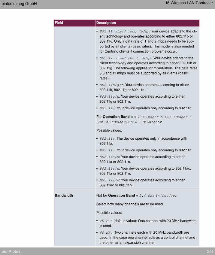
Field Description
• : Your device adapts to the cli-
ent technology and operates according to either 802.11b or
802.11g. Only a data rate of 1 and 2 mbps needs to be sup-
ported by all clients (basic rates). This mode is also needed
for Centrino clients if connection problems occur.
• : Your device adapts to the
client technology and operates according to either 802.11b or
802.11g. The following applies for mixed-short: The data rates
5.5 and 11 mbps must be supported by all clients (basic
rates).
• : Your device operates according to either
802.11b, 802.11g or 802.11n.
• : Your device operates according to either
802.11g or 802.11n.
• : Your device operates only according to 802.11n.
For Operation Band = , ,
or
Possible values:
• : The device operates only in accordance with
802.11a.
• : Your device operates only according to 802.11n.
• : Your device operates according to either
802.11a or 802.11n.
• : Your device operates according to 802.11ac,
802.11a or 802.11n.
• : Your device operates according to either
802.11ac or 802.11n.
Bandwidth Not for Operation Band =
Select how many channels are to be used.
Possible values:
• (default value): One channel with 20 MHz bandwidth
is used.
• : Two channels each with 20 MHz bandwidth are
used. In the case one channel acts as a control channel and
the other as an expansion channel.
bintec elmeg GmbH 16 Wireless LAN Controller
be.IP plus 341
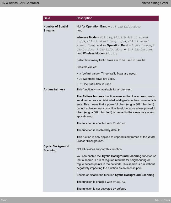
Field Description
Number of Spatial
Streams
Not for Operation Band =
and
Wireless Mode = , ,
, ,
and for Operation Band = ,
, or
and Wireless Mode=
Select how many traffic flows are to be used in parallel.
Possible values:
• (default value): Three traffic flows are used.
• : Two traffic flows are used.
• : One traffic flow is used.
Airtime fairness This function is not available for all devices.
The Airtime fairness function ensures that the access point's
send resources are distributed intelligently to the connected cli-
ents. This means that a powerful client (e. g. a 802.11n client)
cannot achieve only a poor flow level, because a less powerful
client (e. g. a 802.11a client) is treated in the same way when
apportioning.
The function is enabled with .
The function is disabled by default.
This fuction is only applied to unprioritized frames of the WMM
Classe "Background".
Cyclic Background
Scanning Not all devices support this function.
You can enable the Cyclic Background Scanning function so
that a search is run at regular intervals for neighbouring or
rogue access points in the network. This search is run without
negatively impacting the function as an access point.
Enable or disable the function Cyclic Background Scanning .
The function is enabled with .
The function is not activated by default.
16 Wireless LAN Controller bintec elmeg GmbH
342 be.IP plus
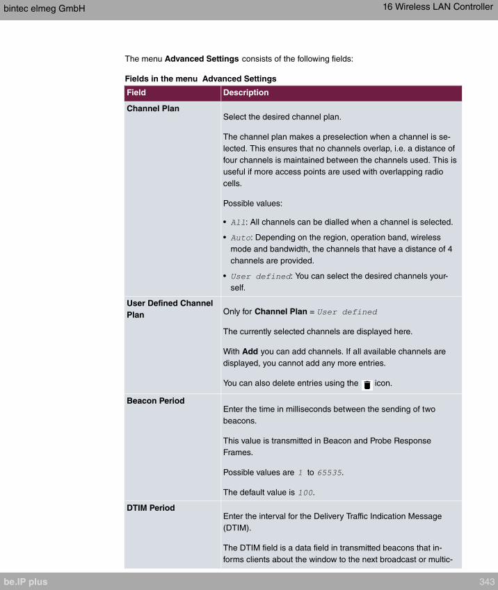
The menu Advanced Settings consists of the following fields:
Fields in the menu Advanced Settings
Field Description
Channel PlanSelect the desired channel plan.
The channel plan makes a preselection when a channel is se-
lected. This ensures that no channels overlap, i.e. a distance of
four channels is maintained between the channels used. This is
useful if more access points are used with overlapping radio
cells.
Possible values:
• : All channels can be dialled when a channel is selected.
• : Depending on the region, operation band, wireless
mode and bandwidth, the channels that have a distance of 4
channels are provided.
• : You can select the desired channels your-
self.
User Defined Channel
Plan Only for Channel Plan =
The currently selected channels are displayed here.
With Add you can add channels. If all available channels are
displayed, you cannot add any more entries.
You can also delete entries using the icon.
Beacon PeriodEnter the time in milliseconds between the sending of two
beacons.
This value is transmitted in Beacon and Probe Response
Frames.
Possible values are to .
The default value is .
DTIM PeriodEnter the interval for the Delivery Traffic Indication Message
(DTIM).
The DTIM field is a data field in transmitted beacons that in-
forms clients about the window to the next broadcast or multic-
bintec elmeg GmbH 16 Wireless LAN Controller
be.IP plus 343
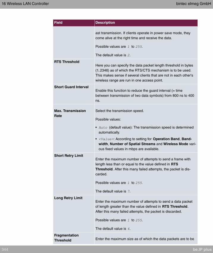
Field Description
ast transmission. If clients operate in power save mode, they
come alive at the right time and receive the data.
Possible values are to .
The default value is .
RTS ThresholdHere you can specify the data packet length threshold in bytes
(1..2346) as of which the RTS/CTS mechanism is to be used.
This makes sense if several clients that are not in each other's
wireless range are run in one access point.
Short Guard IntervalEnable this function to reduce the guard interval (= time
between transmission of two data symbols) from 800 ns to 400
ns.
Max. Transmission
Rate
Select the transmission speed.
Possible values:
• (default value): The transmission speed is determined
automatically.
• : According to setting for Operation Band, Band-
width, Number of Spatial Streams and Wireless Mode vari-
ous fixed values in mbps are available.
Short Retry LimitEnter the maximum number of attempts to send a frame with
length less than or equal to the value defined in RTS
Threshold. After this many failed attempts, the packet is dis-
carded.
Possible values are to .
The default value is .
Long Retry LimitEnter the maximum number of attempts to send a data packet
of length greater than the value defined in RTS Threshold.
After this many failed attempts, the packet is discarded.
Possible values are to .
The default value is .
Fragmentation
Threshold Enter the maximum size as of which the data packets are to be
16 Wireless LAN Controller bintec elmeg GmbH
344 be.IP plus
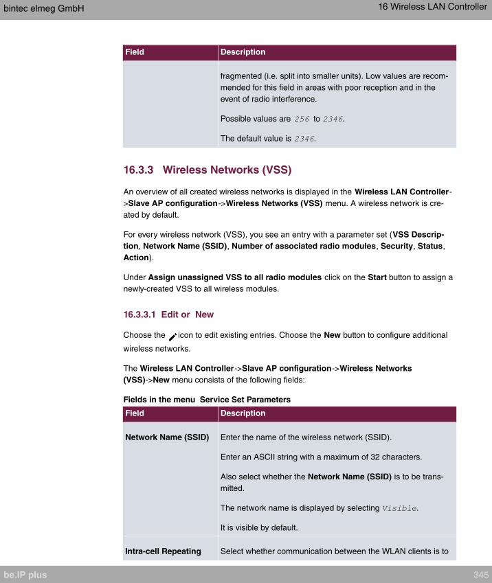
Field Description
fragmented (i.e. split into smaller units). Low values are recom-
mended for this field in areas with poor reception and in the
event of radio interference.
Possible values are to .
The default value is .
16.3.3 Wireless Networks (VSS)
An overview of all created wireless networks is displayed in the Wireless LAN Controller-
>Slave AP configuration->Wireless Networks (VSS) menu. A wireless network is cre-
ated by default.
For every wireless network (VSS), you see an entry with a parameter set (VSS Descrip-
tion, Network Name (SSID), Number of associated radio modules, Security, Status,
Action).
Under Assign unassigned VSS to all radio modules click on the Start button to assign a
newly-created VSS to all wireless modules.
16.3.3.1 Edit or New
Choose the icon to edit existing entries. Choose the New button to configure additional
wireless networks.
The Wireless LAN Controller->Slave AP configuration->Wireless Networks
(VSS)->New menu consists of the following fields:
Fields in the menu Service Set Parameters
Field Description
Network Name (SSID) Enter the name of the wireless network (SSID).
Enter an ASCII string with a maximum of 32 characters.
Also select whether the Network Name (SSID) is to be trans-
mitted.
The network name is displayed by selecting .
It is visible by default.
Intra-cell Repeating Select whether communication between the WLAN clients is to
bintec elmeg GmbH 16 Wireless LAN Controller
be.IP plus 345

Field Description
be permitted within a radio cell.
The function is activated by selecting .
The function is enabled by default.
Users of the guest WLAN should normally have access to the
Internet but no access to the company's intranet. To prevent
this, the option must be disabled. be.
U-APSD Select whether the Unscheduled Automatic Power Save Deliv-
ery (U-APSD) mode is to be enabled.
The function is activated by selecting .
The function is enabled by default.
IGMP Snooping IGMP snooping reduces the data traffic and thus the network
load, as Multicast packets from the LAN are not forwarded. Only
those Multicast packets will be forwarded that are requested by
the respective clients. When you enable IGMP snooping, IGMP
snooping, therefore, provides the framework in which Multicast
is applied.
The function is activated by selecting .
The function is disabled by default.
Fields in the menu Security Settings
Field Description
Security ModeSelect the security mode (encryption and authentication) for the
wireless network.
Possible values:
• (default value): Neither encryption nor authentica-
tion
• : WEP 40 bits
• : WEP 104 bits
• : WPA Preshared Key
• : 802.11x
16 Wireless LAN Controller bintec elmeg GmbH
346 be.IP plus

Field Description
Transmit KeyOnly for Security Mode = or
Select one of the keys configured in WEP Key as a standard
key.
The default value is .
WEP Key 1-4 Only for Security Mode = ,
Enter the WEP key.
Enter a character string with the right number of characters for
the selected WEP mode. For you need a character
string with 5 characters, for with 13 characters.
WPA ModeOnly for Security Mode = and
Select whether you want to use WPA (with TKIP encryption) or
WPA 2 (with AES encryption), or both.
Possible values:
• (default value): WPA and WPA 2 can be
used.
• : Only WPA is used.
• : Only WPA2 is used.
WPA CipherOnly for Security Mode = and
and for WPA Mode = and
Select the type of encryption you want to apply to WPA.
Possible values:
• (default value): TKIP is used.
• : AES is used.
• : AES or TKIP is used.
WPA2 CipherOnly for Security Mode = and
and for WPA Mode = and
Select the type of encryption you want to apply to WPA2.
bintec elmeg GmbH 16 Wireless LAN Controller
be.IP plus 347
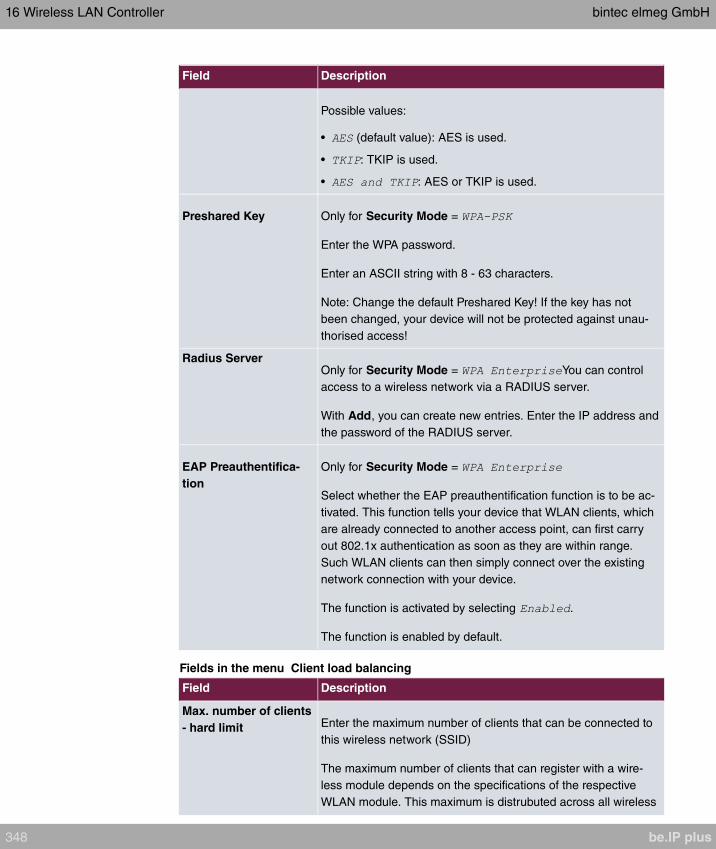
Field Description
Possible values:
• (default value): AES is used.
• : TKIP is used.
• : AES or TKIP is used.
Preshared Key Only for Security Mode =
Enter the WPA password.
Enter an ASCII string with 8 - 63 characters.
Note: Change the default Preshared Key! If the key has not
been changed, your device will not be protected against unau-
thorised access!
Radius ServerOnly for Security Mode = You can control
access to a wireless network via a RADIUS server.
With Add, you can create new entries. Enter the IP address and
the password of the RADIUS server.
EAP Preauthentifica-
tion
Only for Security Mode =
Select whether the EAP preauthentification function is to be ac-
tivated. This function tells your device that WLAN clients, which
are already connected to another access point, can first carry
out 802.1x authentication as soon as they are within range.
Such WLAN clients can then simply connect over the existing
network connection with your device.
The function is activated by selecting .
The function is enabled by default.
Fields in the menu Client load balancing
Field Description
Max. number of clients
- hard limit Enter the maximum number of clients that can be connected to
this wireless network (SSID)
The maximum number of clients that can register with a wire-
less module depends on the specifications of the respective
WLAN module. This maximum is distrubuted across all wireless
16 Wireless LAN Controller bintec elmeg GmbH
348 be.IP plus

Field Description
networks configured for this radio module. No more new wire-
less networks can be created and a warning message will ap-
pear if the maximum number of clients is reached.
Possible values are whole numbers between and .
The default value is .
Max. number of clients
- soft limit Not all devices support this function.
To avoid a radio module being fully utilised, you can set a "soft"
restriction on the number of connected clients. If this number is
reached, new connection queries are initially rejected. If the cli-
ent cannot find another wireless network and, therefore, repeats
its query, the connection is accepted. Queries are only definit-
ively rejected when the Max. number of clients - hard limit is
reached.
The value of the Max. number of clients - soft limit must be
the same as or less than that of the Max. number of clients -
hard limit.
The default value is .
You can disable this function if you set Max. number of clients
- soft limit and Max. number of clients - hard limit to identical
values.
Client Band selectNot all devices support this function.
This function requires a dual radio setup where the same wire-
less networkis configured on both radio modules, but in different
frequency bands.
The Client Band select option enables clients to be moved
from the frequency band originally selected to a less busy one,
providing the client supports this. To achieve a changeover, the
connection attempt of a client is initially refused so that the cli-
ent repeats the attempt in a different frequency band.
Possible values:
• (default
value): The function is not used for this VSS. This is useful if
clients are to switch between different radio cells with as little
bintec elmeg GmbH 16 Wireless LAN Controller
be.IP plus 349

Field Description
delay as possible, e. g. with Voice over WLAN.
• : Preference is given to accept-
ing clients in the 2.4 GHz band.
• : Preference is given to accepting
clients in the 5 GHz band.
Fields in the menu MAC-Filter
Field Description
Access ControlSelect whether only certain clients are to be permitted for this
wireless network.
The function is activated by selecting .
The function is disabled by default.
Allowed AddressesUse Add to make entries and enter the MAC addresses (MAC
Address) of the clients to be permitted.
Dynamic blacklistingYou can use the Dynamic blacklisting function to identify cli-
ents that want to gain possibly unauthorised access to the net-
work and block them for a certain length of time. A client is
blocked if the number of unsuccessful login attempts with a spe-
cified time exceeds a certain number. This threshold value and
the duration of the block can be configured. A blocked client is
blocked at all the APs that are managed by the wireless LAN
controller for the VSS concerned, so neither are they able to log
into a different radio cell in that VSS. If a client needs to be
blocked permanently, this can be done in the Wireless LAN
Controller->Monitoring->Rogue Clients menu.
The function is activated by selecting .
The function is activated by default.
Failed attempts per
Time Enter the number of failed attempts that have to originate from a
specific MAC address during a certain time for a blacklist entry
to be created.
Default values are failed attempts during seconds.
Blacklist blocktimeEnter the time for which an entry in the dynamic blacklist re-
mains valid.
16 Wireless LAN Controller bintec elmeg GmbH
350 be.IP plus
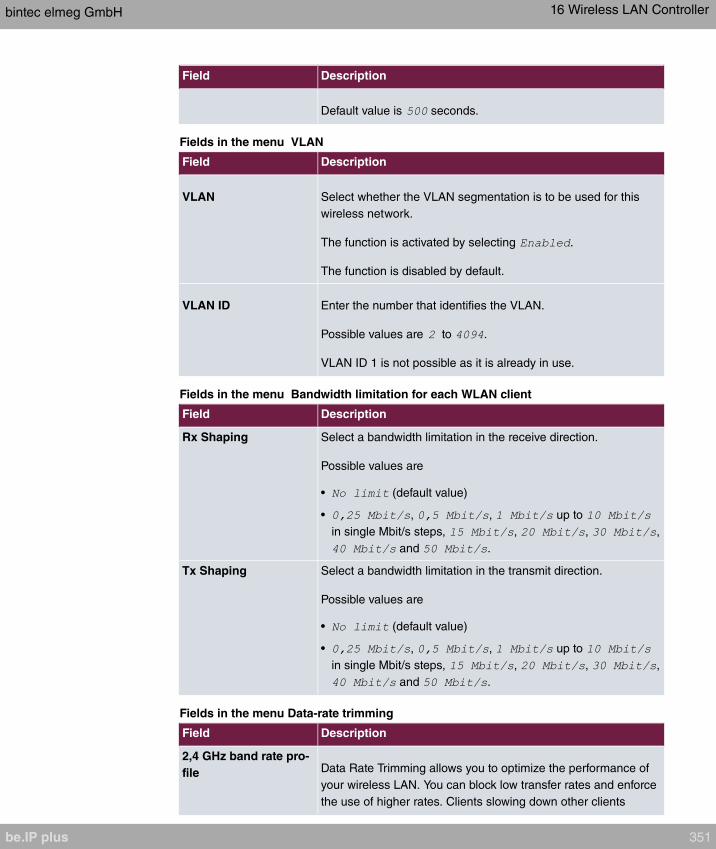
Field Description
Default value is seconds.
Fields in the menu VLAN
Field Description
VLAN Select whether the VLAN segmentation is to be used for this
wireless network.
The function is activated by selecting .
The function is disabled by default.
VLAN ID Enter the number that identifies the VLAN.
Possible values are to .
VLAN ID 1 is not possible as it is already in use.
Fields in the menu Bandwidth limitation for each WLAN client
Field Description
Rx Shaping Select a bandwidth limitation in the receive direction.
Possible values are
• (default value)
• , , up to
in single Mbit/s steps, , , ,
and .
Tx Shaping Select a bandwidth limitation in the transmit direction.
Possible values are
• (default value)
• , , up to
in single Mbit/s steps, , , ,
and .
Fields in the menu Data-rate trimming
Field Description
2,4 GHz band rate pro-
file Data Rate Trimming allows you to optimize the performance of
your wireless LAN. You can block low transfer rates and enforce
the use of higher rates. Clients slowing down other clients
bintec elmeg GmbH 16 Wireless LAN Controller
be.IP plus 351

Field Description
through the use of low transfer rates are disconnected from the
access point.
Select the rate profile to be applied:
• - All clients supporting a transfer
rate of 1 MBit/s are allowed to connect to the access point.
• - see above, for
clients with a minimum supported rate of 6 Mbit/s; clients us-
ing the obsolete standard 802.11b are not allowed.
• - see
above, for clients with a minimum supported rate of 12 Mbit/s
• - see
above, for clients with a minimum supported rate of 24 Mbit/s
5 GHz band rate profilePossible values:
• - All clients supporting a transfer
rate of 6 MBit/s are allowed to connect to the access point.
• - see above, for clients with a minimum
supported rate of 12 Mbit/s
• - see above, for clients with a minimum
supported rate of 24 Mbit/s
Fields in the menu Low RSSI threshold management
Field Description
RSSI thresholdThe option RSSI threshold allows you to define a threshold for
the expected strength of a client signal. If the signal strength of
a client falls below this value for longer than determined by the
Grace time, the client is disconnected from the access
point. This forces the client to connect to a different access
point offering the best possible signal strength.
Specify the lower RSSI threshold in dBm. A client falling below
this value for longer than allowed by the grace time is discon-
nected.
The default value is dBm.
Grace timeSpecify the time (in seconds) during which the signal strength of
a client may fall below the RSSI threshold without the client be-
16 Wireless LAN Controller bintec elmeg GmbH
352 be.IP plus
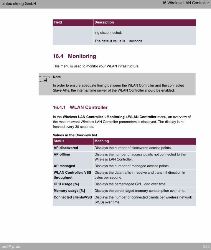
Field Description
ing disconnected.
The default value is seconds.
16.4 Monitoring
This menu is used to monitor your WLAN infrastructure.
Note
In order to ensure adequate timing between the WLAN Controller and the connected
Slave APs, the internal time server of the WLAN Controller should be enabled.
16.4.1 WLAN Controller
In the Wireless LAN Controller->Monitoring->WLAN Controller menu, an overview of
the most relevant Wireless LAN Controller parameters is displayed. The display is re-
freshed every 30 seconds.
Values in the Overview list
Status Meaning
AP discovered Displays the number of discovered access points.
AP offline Displays the number of access points not connected to the
Wireless LAN Controller.
AP managed Displays the number of managed access points.
WLAN Controller: VSS
throughput
Displays the data traffic in receive and transmit direction in
bytes per second.
CPU usage [%] Displays the percentaged CPU load over time.
Memory usage [%] Displays the percentaged memory consumption over time.
Connected clients/VSS Displays the number of connected clients per wireless network
(VSS) over time.
bintec elmeg GmbH 16 Wireless LAN Controller
be.IP plus 353
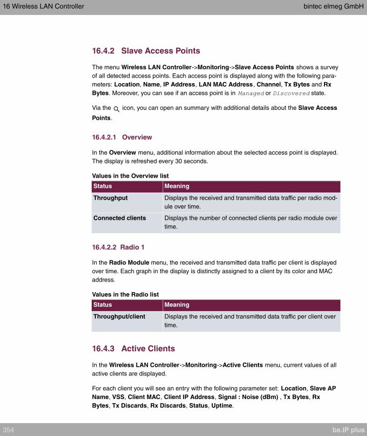
16.4.2 Slave Access Points
The menu Wireless LAN Controller->Monitoring->Slave Access Points shows a survey
of all detected access points. Each access point is displayed along with the following para-
meters: Location, Name, IP Address, LAN MAC Address , Channel, Tx Bytes and Rx
Bytes. Moreover, you can see if an access point is in or state.
Via the icon, you can open an summary with additional details about the Slave Access
Points.
16.4.2.1 Overview
In the Overview menu, additional information about the selected access point is displayed.
The display is refreshed every 30 seconds.
Values in the Overview list
Status Meaning
Throughput Displays the received and transmitted data traffic per radio mod-
ule over time.
Connected clients Displays the number of connected clients per radio module over
time.
16.4.2.2 Radio 1
In the Radio Module menu, the received and transmitted data traffic per client is displayed
over time. Each graph in the display is distinctly assigned to a client by its color and MAC
address.
Values in the Radio list
Status Meaning
Throughput/client Displays the received and transmitted data traffic per client over
time.
16.4.3 Active Clients
In the Wireless LAN Controller->Monitoring->Active Clients menu, current values of all
active clients are displayed.
For each client you will see an entry with the following parameter set: Location, Slave AP
Name, VSS, Client MAC, Client IP Address, Signal : Noise (dBm) , Tx Bytes, Rx
Bytes, Tx Discards, Rx Discards, Status, Uptime.
16 Wireless LAN Controller bintec elmeg GmbH
354 be.IP plus
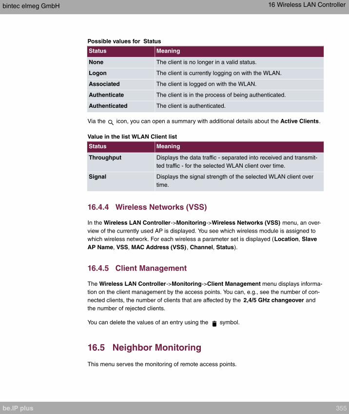
Possible values for Status
Status Meaning
None The client is no longer in a valid status.
Logon The client is currently logging on with the WLAN.
Associated The client is logged on with the WLAN.
Authenticate The client is in the process of being authenticated.
Authenticated The client is authenticated.
Via the icon, you can open a summary with additional details about the Active Clients.
Value in the list WLAN Client list
Status Meaning
Throughput Displays the data traffic - separated into received and transmit-
ted traffic - for the selected WLAN client over time.
Signal Displays the signal strength of the selected WLAN client over
time.
16.4.4 Wireless Networks (VSS)
In the Wireless LAN Controller->Monitoring->Wireless Networks (VSS) menu, an over-
view of the currently used AP is displayed. You see which wireless module is assigned to
which wireless network. For each wireless a parameter set is displayed (Location, Slave
AP Name, VSS, MAC Address (VSS) , Channel, Status).
16.4.5 Client Management
The Wireless LAN Controller->Monitoring->Client Management menu displays informa-
tion on the client management by the access points. You can, e.g., see the number of con-
nected clients, the number of clients that are affected by the 2,4/5 GHz changeover and
the number of rejected clients.
You can delete the values of an entry using the symbol.
16.5 Neighbor Monitoring
This menu serves the monitoring of remote access points.
bintec elmeg GmbH 16 Wireless LAN Controller
be.IP plus 355
16.5.1 Neighbor APs
In the Wireless LAN Controller->Neighbor Monitoring->Neighbor APs menu, the adja-
cent AP's found during the scan are displayed. Rogue APs, i.e. APs which are not man-
aged by the WLAN controller but are using an SSID managed by the WLAN controller are
highlighted in red.
Note
Check the rogue APs shown carefully, as an attacker could attempt to spy on data in
your network using a rogue AP.
Although each AP is found more than once, it is only displayed once with the strongest sig-
nal. You see the following parameters for each AP: SSID, MAC Address , Signal dBm,
Channel, Security, Last seen, Strongest signal received by , Total detections .
The entries are displayed in alphabetical order by SSID. Security shows the security set-
tings of the AP. Under Strongest signal received by, you will see the parameters Loca-
tion and Name of the APs in which the displayed AP was found. Total detections shows
how often the corresponding AP was found during the scan.
Click under New Neighborscan on Start, to rescan adjacent AP's. You will receive a warn-
ing that the wireless modules of the access points must also be disabled for a certain peri-
od of time. When you start the process with OK, a progress bar is displayed. The located
AP display is updated every ten seconds.
16.5.2 Rogue APs
APs which are using an SSID from their own network but are not managed by Wireless
LAN Controller are displayed in the Wireless LAN Controller->Neighbor
Monitoring->Rogue APs menu. Rogue APs which have been found for the first time are
displayed with a red background.
For each rogue AP you will see an entry with the following parameter set: SSID, MAC Ad-
dress, Signal dBm, Channel, Last seen, Detected via AP, Accepted.
Note
Check the rogue APs shown carefully, as an attacker could attempt to spy on data in
your network using a rogue AP.
16 Wireless LAN Controller bintec elmeg GmbH
356 be.IP plus

You can class a rogue AP as trustworthy by enabling the Accepted checkbox. If an alarm
has been configured, this is then removed and no longer sent. The red background disap-
pears.
Click under New Neighborscan on Start, to rescan adjacent AP's. You will receive a warn-
ing that the wireless modules of the access points must also be disabled for a certain peri-
od of time. When you start the process with OK, a progress bar is displayed. The located
AP display is updated every ten seconds.
16.5.3 Rogue Clients
The Wireless LAN Controller->Neighbor Monitoring->Rogue Clients menu displays the
clients which have attempted to gain unauthorised access to the network and which are
therefore on the blacklist. The blacklist is configured for each VSS in the Wireless LAN
Controller->Slave AP configuration->Wireless Networks (VSS) menu. You can also
add a new entry to the static blacklist.
Possible values for Rogue Clients
Status Meaning
Rogue Client MAC Ad-
dress
Displays the MAC address of the client on the blacklist.
Network Name (SSID) Displays the SSID involved.
Attacked Access Point Displays the AP concerned.
Signal dBm Displays the signal strength of the client during the attempted
access.
Type of attack This displays the type of potential attack, e. g. an incorrect au-
thentication.
First seen Displays the time of the first registered attempted access.
Last seen Displays the time of the last registered attempted access.
Static Blacklist You can categorise a rogue client as untrustworthy by selecting
the checkbox in the Static Blacklist column. The block on the
client does not then end automatically, rather you need to lift it
manually.
Delete You can delete entries with the symbol.
16.5.3.1 New
Choose the New button to configure additional blacklist entries.
The menu consists of the following fields:
bintec elmeg GmbH 16 Wireless LAN Controller
be.IP plus 357

Fields in the New Blacklist Entry menu
Field Description
Rogue Client MAC Ad-
dress
Enter the MAC address of the client you intend to include in the
static blacklist.
Network Name (SSID) Pick the wireless network you want to exclude the rogue client
from.
16.6 Maintenance
This menu is used for the maintenance of your managed APs.
16.6.1 Firmware Maintenance
In the Wireless LAN Controller->Maintenance->Firmware Maintenance menu, a list of
all Managed Access Points is displayed.
For each managed AP you will see an entry with the following parameter set: Update firm-
ware, Location, Device, IP Address, LAN MAC Address , Firmware Version , Status.
Click the Select all button to select all of the entries for a firmware update. Click the
Deselect all button to disable all entries and to then select individual entries if required
(e.g. if there is a large number of entries and only individual APs are to be given software
updates).
Possible values for Status
Status Meaning
Image already exists. The software image already exists; no update is required.
Error An error has occurred.
Running The operation is currently in progress.
Done The update is complete.
The Wireless LAN Controller->Maintenance->Firmware Maintenance menu consists of
the following fields:
Fields in the Firmware Maintenance menu
Field Description
ActionSelect the action you wish to execute.
After each task, a window is displayed showing the other steps
16 Wireless LAN Controller bintec elmeg GmbH
358 be.IP plus

Field Description
that are required.
Possible values:
• : You can also start an update
of the system software.
• : You
can save a configuration which contains the AP status inform-
ation.
Source LocationSelect the source for the action.
Possible values:
• (default value): The file is stored respectively
on a remote server specified in the URL.
• : The file is on
the official update server. (Only for Action=
)
• : The file is stored respectively on a TFTP
server specified in the URL.
URLOnly for Source Location = or
Enter the URL of the update server from which the system soft-
ware file is loaded or on which the configuration file is saved.
bintec elmeg GmbH 16 Wireless LAN Controller
be.IP plus 359
Chapter 17 Networking
17.1 Routes
Default Route
With a default route, all data is automatically forwarded to one connection if no other suit-
able route is available. If you set up access to the Internet, you must configure the route to
your Internet Service Provider (ISP) as a default route. If, for example, you configure a cor-
porate network connection, only enter the route to the head office or branch office as a de-
fault route if you do not configure Internet access over your device. If, for example, you
configure both Internet access and a corporate network connection, enter a default route to
the ISP and a network route to the head office. You can enter several default routes on
your device, but only one default route can be active at any one time. If you enter several
default routes, you should thus note differing values for Metric.
17.1.1 IPv4 Route Configuration
A list of all configured routes is displayed in the Network->Routes->IPv4 Route Configur-
ation menu.
In the ex works state, a predefined entry with the parameters Destination IP Address =
, Netmask = ,Gateway = , Interface =
, Route Type = is displayed.
17.1.1.1 Edit or New
Choose the icon to edit existing entries. Choose the New button to create additional
routes.
If the option is selected for the Route Class, an extra configuration section
opens.
The Network->Routes->IPv4 Route Configuration->New menu consists of the following
fields:
Fields in the menu Basic Parameters
Field Description
Route Type Select the type of route.
17 Networking bintec elmeg GmbH
360 be.IP plus

Field Description
Possible values:
• : Route via a specific in-
terface which is to be used if no other suitable route is avail-
able.
• : Route via a specific gate-
way which is to be used if no other suitable route is available.
• : Route to an individual host
via a specific interface.
• : Route to an individual host via
a specific gateway.
• (default value): Route to
a network via a specific interface.
• : Route to a network via a
specific gateway.
Only for interfaces that are operated in DHCP client mode:
Even if an interface is configured for DHCP client mode, routes
can still be configured for data traffic via that interface. The set-
tings received from the DHCP server are then copied, along
with those configured here, to the active routing table. This en-
ables, e. g., in the case of dynamically changing gateway ad-
dresses, particular routes to be maintained, or routes with differ-
ent metrics (i. e. of differing priority) to be specified. However, if
the DHCP server sends static routes, the settings configured
here are not copied to the routing.
• : The information of
the gateway to be used is received via DHCP and integrated
into the route.
• : The settings received
by DHCP are supplemented by routing information about a
particular host.
• : The settings re-
ceived by DHCP are supplemented by routing information
about a particular network.
bintec elmeg GmbH 17 Networking
be.IP plus 361

Field Description
Note
When the DHCP lease expires or when the device is re-
started, the routes that consist from the combination of DH-
CP settings and those made here are initially deleted once
more from the active routing. If the DHCP is reconfigured
they are re-generated and re-activated.
Interface Select the interface to be used for this route.
Route Class Select the type of Route Class.
Possible values:
• (default value): Defines a route with the default
parameters.
• : Select whether the route is to be defined with ex-
tended parameters. If the function is active, a route is created
with extended routing parameters such as source interface
and source IP address, as well as protocol, source and des-
tination port, type of service (TOS) and the status of the
device interface.
Fields in the menu Route Parameters
Field Description
Local IP Address Only for Route Type = ,
or
Enter the own IP address of the router on the selected interface.
Destination IP Ad-
dress/Netmask
Only for Route Type or
Enter the IP address of the destination host or destination net-
work.
When Route Type =
Also enter the relevant netmask in the second field.
17 Networking bintec elmeg GmbH
362 be.IP plus

Field Description
Gateway IP AddressOnly for Route Type = ,
or
Enter the IP address of the gateway to which your device is to
forward the IP packets.
Metric Select the priority of the route.
The lower the value, the higher the priority of the route.
Value range from to . The default value is .
Fields in the menu Extended Route Parameters
Field Description
Description Enter a description for the IP route.
Source Interface Select the interface over which the data packets are to reach
the device.
The default value is .
Source IP Address/
Netmask
Enter the IP address and netmask of the source host or source
network.
Layer 4 Protocol Select a protocol.
Possible values: , ,
, ,
, , , , , , .
The default value is .
Source Port Only for Layer 4 Protocol = or
Enter the source port.
First select the port number range.
Possible values:
• (default value): The route is valid for all port numbers.
• : Enables the entry of a port number.
bintec elmeg GmbH 17 Networking
be.IP plus 363

Field Description
• : Enables the entry of a range of port numbers.
• : Entry of privileged port numbers: 0 ... 1023.
• : Entry of server port numbers: 5000 ... 32767.
• : Entry of client port numbers: 1024 ... 4999.
• : Entry of client port numbers: 32768 ... 65535.
• : Entry of unprivileged port numbers: 1024
... 65535.
Enter the appropriate values for the individual port or start port
of a range in Port and, for a range, the end port in to Port.
Destination Port Only for Layer 4 Protocol = or
Enter the destination port.
First select the port number range.
Possible values:
• (default value): The route is valid for all port numbers.
• : Enables the entry of a port number.
• : Enables the entry of a range of port numbers.
• : Entry of privileged port numbers: 0 ... 1023.
• : Entry of server port numbers: 5000 ... 32767.
• : Entry of client port numbers: 1024 ... 4999.
• : Entry of client port numbers: 32768 ... 65535.
• : Entry of unprivileged port numbers: 1024
... 65535.
Enter the appropriate values for the individual port or start port
of a range in Port and, for a range, the end port in to Port.
DSCP / TOS Value Select the Type of Service (TOS).
Possible values:
• (default value): The type of service is ignored.
• : Differentiated Services Code Point
according to RFC 3260 is used to signal the priority of IP
packets (indicated in binary format).
• : Differentiated Services Code Point
17 Networking bintec elmeg GmbH
364 be.IP plus
Field Description
according to RFC 3260 is used to signal the priority of IP
packets (indicated in decimal format).
• : Differentiated Services Code
Point according to RFC 3260 is used to signal the priority of
IP packets (indicated in hexadecimal format).
• : The TOS value is specified in binary
format, e.g. 00111111.
• : The TOS value is specified in decimal
format, e.g. 63.
• : The TOS value is specified in
hexadecimal format, e.g. 3F.
Enter the relevant value for ,
, ,
, and
.
Mode Select when the interface defined in Route Parameters ->Inter-
face is to be used.
Possible values:
• (default value): The route can be used if
the interface is "up". If the interface is "dormant", then dial and
wait until the interface is "up".
• : The route can always be used.
• : The route can be used when the
interface is "up". If the interface is "dormant", then select and
use the alternative route (rerouting) until the interface is "up".
• : The route can be used when the interface is
"up".
• : The route can be used when the interface
is "up". If the interface is "dormant", then dial and wait until the
interface is "up". In this case, an alternative interface with a
poorer metric is used for routing until the interface is "up".
17.1.2 IPv6 Route Configuration
A list of all configured IPv6 routes is displayed in the Network->Routes->IPv6 Route Con-
figuration menu.
bintec elmeg GmbH 17 Networking
be.IP plus 365

17.1.2.1 Edit or New
Choose the icon to edit existing entries. Choose the New button to create additional
routes.
Routes without an icon have been created by the router automatically and cannot be
edited.
The Network->Routes->IPv6 Route Configuration->New menu consists of the following
fields:
Fields in the Route Parameters menu
Field Description
Description Enter a description for the IPv6 route.
Route Active Select if the route is to be active or inactive..
With the status of the route will be set to active.
The function is enabled by default.
Route Type Select the type of route.
Possible values:
• : Route via a specific in-
terface which is used if no other adequate route is available.
• : Route via a specific gate-
way which is used if no other adequate route is available.
• : Route to a single host via a
specific interface.
• : Route to a single host via a
specific gateway.
• : Route to a network via
a specific interface.
• (default value): Route to a
network via a specific gateway.
Destination Interface Select the IPv6 interface to be used for this route.
You can choose from those interfaces available under LAN->IP
Configuration->Interfaces->New that are IPv6-enabled.
17 Networking bintec elmeg GmbH
366 be.IP plus

Field Description
Source Address /
Length
Enter the source IPv6 address along with the corresponding
prefix length.
describes an unspecific address.
By default the prefix length is predefined.
Destination Address /
Length
Enter the destination IPv6 address along with the corresponding
prefix length.
describes an unspecific address.
By default the prefix length is predefined.
Gateway Address Enter a the IPv6 address for the next hop.
Metric Select the priority of the route.
The lower the value, the higher the priority of the route.
Value range from to . The default value is .
17.1.3 IPv4 Routing Table
A list of all IPv4 routes is displayed in the Network->Routes->IPv4 Routing Table menu.
The routes do not all need to be active, but can be activated at any time by relevant data
traffic.
In the ex works state, a predefined entry with the parameters Destination IP Address =
, Netmask = ,Gateway = , Interface =
, Route Type = , Protocol = is
displayed.
Fields in the menu IPv4 Routing Table
Field Description
Destination IP AddressDisplays the IP address of the destination host or destination
network.
NetmaskDisplays the netmask of the destination host or destination net-
work.
GatewayDisplays the gateway IP address. Nothing is displayed here
bintec elmeg GmbH 17 Networking
be.IP plus 367
Field Description
when routes are received by DHCP.
InterfaceDisplays the interface used for this route.
MetricDisplays the route's priority.
The lower the value, the higher the priority of the route.
Route TypeDisplays the route type.
Extended RouteDisplays whether a route has been configured with advanced
parameters.
ProtocolDisplays how the entry has been created , e.g. manually (
) or via one of the available protocols.
Delete You can delete entries with the symbol.
17.1.4 IPv6 Routing Table
A list of all configured IPv6 routes is displayed in the Network->Routes->IPv6 Routing Ta-
ble menu.
Fields in the IPv6 Routing Table menu
Field Description
RouteDisplays the source and destination address, which is used for
this route, as well as the gateway IP address. Nothing is dis-
played here when routes are received by DHCP.
InterfaceDisplays the interface used for this route.
MetricDisplays the route's priority.
The lower the value, the higher the priority of the route.
ProtocolDisplays how the entry has been created , e.g. manually (
) or via one of the available protocols.
17 Networking bintec elmeg GmbH
368 be.IP plus

17.1.5 Options
Back Route Verify
The term Back Route Verify describes a very simple but powerful function. If a check is ac-
tivated for an interface, incoming data packets are only accepted over this interface if out-
going response packets are routed over the same interface. You can therefore prevent the
acceptance of packets with false IP addresses - even without using filters.
In the ex works state, the two entries and are displayed by default set-
ting .
The Networking->Routes->Options menu consists of the following fields:
Fields in the Back Route Verify menu.
Field Description
Mode Select how the interfaces to be activated for Back Route Verify
are to be specified.
Possible values:
• : Back Route Verify is activ-
ated for all interfaces.
• (default value): A
list of all interfaces is displayed in which Back Route Verify is
only enabled for specific interfaces.
• : Back route verify is dis-
abled for all interfaces.
No. Only for Mode =
Displays the serial number of the list entry.
Interface Only for Mode =
Displays the name of the interface.
Back Route Verify Only for Mode =
Select whether is to be activated for the
interface.
The function is enabled with .
bintec elmeg GmbH 17 Networking
be.IP plus 369

Field Description
By default, the function is deactivated for all interfaces.
17.2 IPv6 General Prefixes
IPv6 General Prefixes are usually distributed by IPv6 providers. They can be statically as-
signed or obtained through DHCP. In most cases, they define /48 or /56 networks. You can
derive /64 subnets from these prefixes and have them distributed in your network.
General Prefixes have two key advantages:
• A single route is sufficient for all traffic between the provider and the customer.
• If your provider assigns a new General Prefix through DHCP or changes the static Gen-
eral Prefix assigned to you, there is little or no configuration to be done: In the case of
DHCP you obtain the new General Prefix automatically; and in the case of a statically as-
signed General Prefix, you need to introduce it into your system once. All subnets and
IPv6 addresses derived from the General Prefix change automatically after an update.
In order to IPv6 you need to configure how subnets and IPV6 addresses are created and
distributed (see Configuring IPv6 addresses in Interfaces on page 289 and the menu LAN-
>IP Configuration->Interfaces for the IPv6-relevant parameters.
17.2.1 General Prefix Configuration
A list of all configured IPv6 prefixes is displayed in the Networking->IPv6 General Pre-
fixes->General Prefix Configuration menu.
17.2.1.1 Edit or New
Choose the icon to edit existing entries. Choose the New button to create additional
prefixes.
Fields in the Basic Parameters menu.
Field Description
General Prefix active Select if the prefix is to be active or inactive..
With the status of the prefix will be set to active.
The function is enabled by default.
NameEnter a name for the General Prefix.
17 Networking bintec elmeg GmbH
370 be.IP plus
Field Description
A meaningful name helps selecting the General Prefix from a
prefix list.
TypeSpecify how the address range is to be assigned.
Possible values:
• (default value): The general prefix will be set dy-
namically by DHCP transmission, e.g. from a provider.
• : The prefix is fixed, e. g. by a provider.
From Interface Only with Type =
Select the IPv6 interface from which a General Prefix is to be
obtained.
You can choose from all interfaces that are availabe under
LAN->IP Configuration->Interfaces->New and that fullfil the
following conditions:
• IPv6 is .
• IPv6 Mode =
• DHCP Client is .
Used Prefix / Length Only with Type =
Enter the prefix to be used. Enter the corresponding length. This
prefix must end with ::.
The default value is .
17.3 NAT
Network Address Translation (NAT) is a function on your device for defined conversion of
source and destination addresses of IP packets. If NAT is activated, IP connections are still
only allowed by default in one direction, outgoing (forward) (= protective function). Excep-
tions to the rule can be configured (in NAT Configuration on page 373).
Specific instructions for configuring NAT, see the end of the chapter NAT - Configuration
example on page 378.
bintec elmeg GmbH 17 Networking
be.IP plus 371

17.3.1 NAT Interfaces
A list of all NAT interfaces is displayed in the Networking->NAT->NAT Interfaces menu.
For every NAT interface, the , , and
can be selected.
In addition, displays how many port forwarding rules were configured
for this interface.
Options in the menu NAT Interfaces
Field Description
NAT active Select whether NAT is to be activated for the interface.
The function is disabled by default.
Loopback active The NAT loopback function also enables network address trans-
lation for connectors whereby NAT is not activated. This is often
used in order to interpret queries from the LAN as if they were
coming from the WAN. You can use this to test the server ser-
vices.
The function is disabled by default.
Silent Deny Select whether IP packets are to be silently denied by NAT. If
this function is deactivated, the sender of the denied IP packet
is informed by means of an appropriate ICMP or TCP RST mes-
sage.
The function is disabled by default.
PPTP Passthrough Select whether the setup and operation of several simultan-
eous, outgoing PPTP connections from hosts in the network are
also to be permitted if NAT is activated.
The function is disabled by default.
If PPTP Passthrough is enabled, the device itself cannot be
configured as a tunnel endpoint.
Portforwardings Shows the number of portforwarding rules configured in Net-
working->NAT->NAT Configuration .
17 Networking bintec elmeg GmbH
372 be.IP plus

17.3.2 NAT Configuration
In the Networking->NAT->NAT Configuration menu you can exclude data from NAT
simply and conveniently as well as translate addresses and ports. For outgoing data traffic
you can configure various NAT methods, i.e. you can determine how an external host es-
tablishes a connection to an internal host.
17.3.2.1 New
Choose the New button to set up NAT.
The Networking->NAT->NAT Configuration ->New menu consists of the following fields:
Fields in the menu Basic Parameters
Field Description
Description Enter a description for the NAT configuration.
Interface Select the interface for which NAT is to be configured.
Possible values:
• (default value): NAT is configured for all interfaces.
• : Select one of the interfaces from the
list.
Type of trafficSelect the type of data traffic for which NAT is to be configured.
Possible values:
• (default value): The data
traffic that comes from outside.
• : Outgoing data traffic.
• : Data traffic excluded from
NAT.
NAT methodOnly for Type of traffic =
Select the NAT method for outgoing data traffic. The starting
point for choosing the NAT method is a NAT scenario in which
an "internal" source host has initiated an IP connection to an "ex-
ternal" destination host over the NAT interface, and in which an
internally valid source address and internally valid source port
are translated to an externally valid source address and an ex-
ternally valid source port.
bintec elmeg GmbH 17 Networking
be.IP plus 373

Field Description
Possible values:
• (UDP only): Any given external host may send IP
packets via the external address and the external port to the
initiating source address and the initial source port.
• (UDP only): Like full-cone NAT; as ex-
ternal host, however, only the initial "external" destination host
is allowed.
• (UDP only): Like restricted-cone
NAT; however, exclusively data from the initial destination
port are allowed.
• (standard value) any protocol: Outbound, an ex-
ternally valid source address and an externally valid source
port are administratively set. Inbound, only response packets
within the existing connection are allowed.
In the NAT Configuration ->Specify original traffic menu, you can configure for which
data traffic NAT is to be used.
Fields in the menu Specify original traffic
Field Description
Service Not for Type of traffic = and NAT
method = , or
.
Select one of the preconfigured services.
Possible values:
• (default value)
•
Action Only for Type of traffic =
Select which data packets are to be excluded by NAT.
Possible values:
• (default value): All the data packets that match the
following parameters that are to be configured (protocol,
source IP address/network mask, destination IP address/net-
mask, etc.) are excluded by NAT.
17 Networking bintec elmeg GmbH
374 be.IP plus
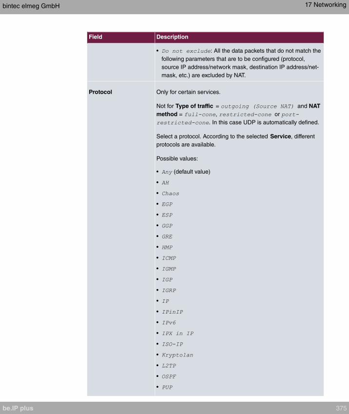
Field Description
• : All the data packets that do not match the
following parameters that are to be configured (protocol,
source IP address/network mask, destination IP address/net-
mask, etc.) are excluded by NAT.
Protocol Only for certain services.
Not for Type of traffic = and NAT
method = , or
. In this case UDP is automatically defined.
Select a protocol. According to the selected Service, different
protocols are available.
Possible values:
• (default value)
•
•
•
•
•
•
•
•
•
•
•
•
•
•
•
•
•
•
•
•
bintec elmeg GmbH 17 Networking
be.IP plus 375
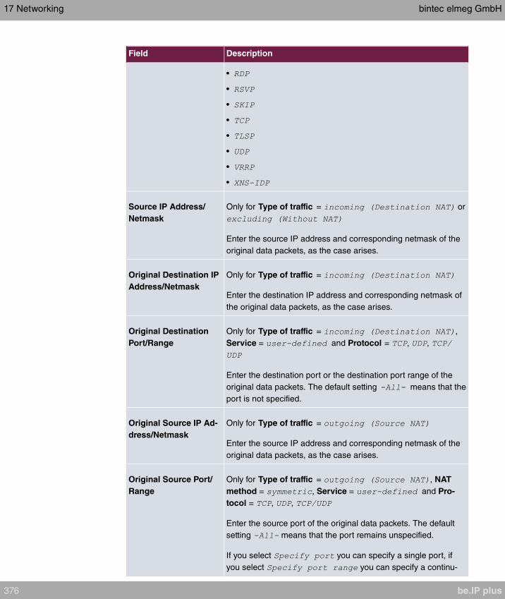
Field Description
•
•
•
•
•
•
•
•
Source IP Address/
Netmask
Only for Type of traffic = or
Enter the source IP address and corresponding netmask of the
original data packets, as the case arises.
Original Destination IP
Address/Netmask
Only for Type of traffic =
Enter the destination IP address and corresponding netmask of
the original data packets, as the case arises.
Original Destination
Port/Range
Only for Type of traffic = ,
Service = and Protocol = , ,
Enter the destination port or the destination port range of the
original data packets. The default setting means that the
port is not specified.
Original Source IP Ad-
dress/Netmask
Only for Type of traffic =
Enter the source IP address and corresponding netmask of the
original data packets, as the case arises.
Original Source Port/
Range
Only for Type of traffic = , NAT
method = , Service = and Pro-
tocol = , ,
Enter the source port of the original data packets. The default
setting means that the port remains unspecified.
If you select you can specify a single port, if
you select you can specify a continu-
17 Networking bintec elmeg GmbH
376 be.IP plus

Field Description
ous range of ports which will be a applied for filtering the outgo-
ing data traffic
Source Port/Range Only for Type of traffic = , Ser-
vice = and Protocol = , ,
Enter the source port or the source port range of the original
data packets. The default setting means that the port re-
mains unspecified.
Destination IP Ad-
dress/Netmask
Only for Type of traffic = or
and NAT method =
Enter the destination IP address and corresponding netmask of
the original data packets, as the case arises.
Destination Port/Range Only for Type of traffic = , NAT
method = , Service = and Pro-
tocol = , , or Type of traffic =
, Service = and Protocol =
, ,
Enter the destination port or the destination port range of the
original data packets. The default setting means that the
port remains unspecified.
In the NAT Configuration ->Replacement Values menu you can define, depending on
whether you're dealing with inbound or outbound data traffic, new addresses and ports, to
which specific addresses and ports from the NAT Configuration ->Specify original traffic
menu can be translated.
Fields in the menu Replacement Values
Field Description
New Destination IP Ad-
dress/Netmask
Only for Type of traffic =
Enter the destination IP address and corresponding netmask to
which the original destination IP address is to be translated.
New Destination Port Only for Type of traffic = ,
Service = and Protocol = , ,
Leave the destination port as it appears or enter the destination
bintec elmeg GmbH 17 Networking
be.IP plus 377

Field Description
port to which the original destination port is to be translated.
Select to leave the original destination port. If you
disable , an input field appears and you can enter a
new destination port.
is active by default.
New Source IP Ad-
dress/Netmask
Only for Type of traffic = and
NAT method =
Enter the source IP address to which the original source IP ad-
dress is to be translated, with corresponding netmask, as the
case arises.
New Source Port Only for Type of traffic = , NAT
method = , Service = , Protocol =
, , and Original Source Port/Range=
or
Leave the source port as it appears or enter a new source port
to which the original source port is to be translated.
leaves the original source port. If you disable
, an input field appears in which you can enter a new
source port. is active by default.
If you select for Original Source Port/
Range, you can choose from the following options:
• : The range specified
for Original Source Port/Range is not changed, all port num-
bers are retained.
• : There is an
input field for you to specify the port number with which to
start the port range that replaces the original port rannge. The
count of ports is retained.
17.3.3 NAT - Configuration example
Requirements
• Basic configuration of the gateway
17 Networking bintec elmeg GmbH
378 be.IP plus
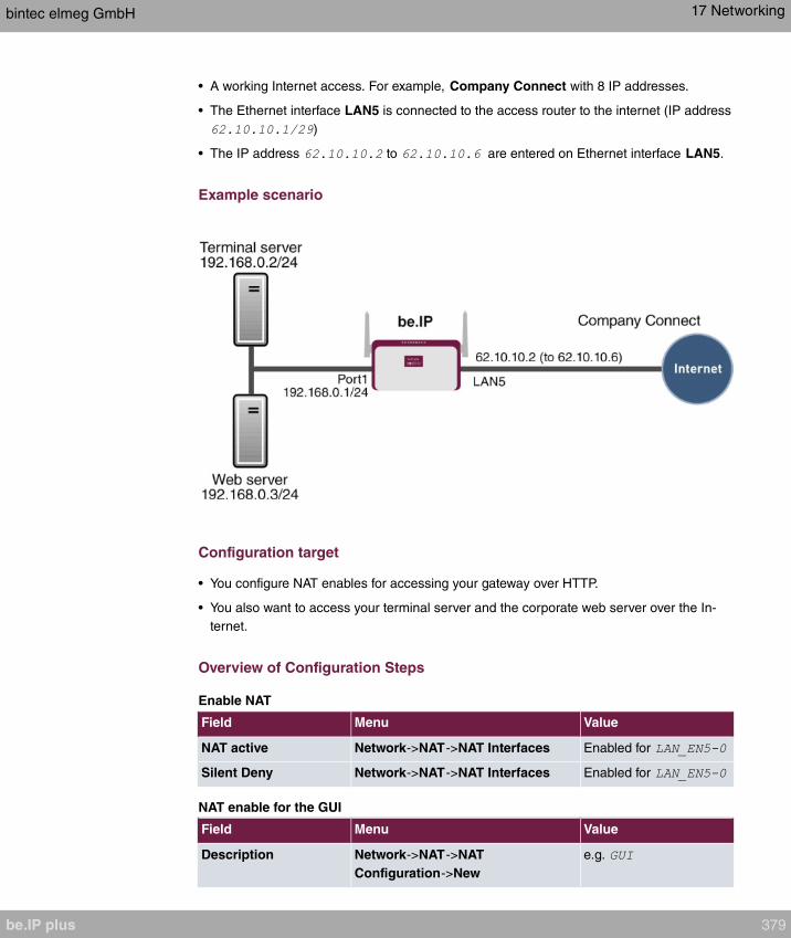
• A working Internet access. For example, Company Connect with 8 IP addresses.
• The Ethernet interface LAN5 is connected to the access router to the internet (IP address
)
• The IP address to are entered on Ethernet interface LAN5.
Example scenario
Configuration target
• You configure NAT enables for accessing your gateway over HTTP.
• You also want to access your terminal server and the corporate web server over the In-
ternet.
Overview of Configuration Steps
Enable NAT
Field Menu Value
NAT active Network->NAT->NAT Interfaces Enabled for
Silent Deny Network->NAT->NAT Interfaces Enabled for
NAT enable for the GUI
Field Menu Value
Description Network->NAT->NAT
Configuration->New
e.g.
bintec elmeg GmbH 17 Networking
be.IP plus 379

Field Menu Value
Interface Network->NAT->NAT
Configuration->New
Type of traffic Network->NAT->NAT
Configuration->New
Service Network->NAT->NAT
Configuration->New
Protocol Network->NAT->NAT
Configuration->New
Source IP Address/
Netmask
Network->NAT->NAT
Configuration->New
Original Destination IP
Address/Netmask
Network->NAT->NAT
Configuration->New
, e.g.
Original Destination
Port/Range
Network->NAT->NAT
Configuration->New
,
New Destination IP Ad-
dress/Netmask
Network->NAT->NAT
Configuration->New
, e.g.
New Destination Port Network->NAT->NAT
Configuration->New
disabled,
Web server
Field Menu Value
Description Network->NAT->NAT
Configuration->New
e.g.
Interface Network->NAT->NAT
Configuration->New
Type of traffic Network->NAT->NAT
Configuration->New
Service Network->NAT->NAT
Configuration->New
Source IP Address/
Netmask
Network->NAT->NAT
Configuration->New
Original Destination IP
Address/Netmask
Network->NAT->NAT
Configuration->New , e.g.
New Destination IP Ad-
dress/Netmask
Network->NAT->NAT
Configuration->New , e.g.
New Destination Port Network->NAT->NAT
17 Networking bintec elmeg GmbH
380 be.IP plus
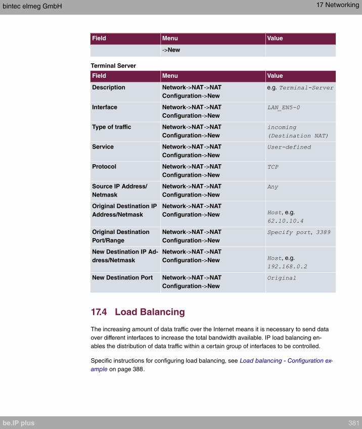
Field Menu Value
->New
Terminal Server
Field Menu Value
Description Network->NAT->NAT
Configuration->New
e.g.
Interface Network->NAT->NAT
Configuration->New
Type of traffic Network->NAT->NAT
Configuration->New
Service Network->NAT->NAT
Configuration->New
Protocol Network->NAT->NAT
Configuration->New
Source IP Address/
Netmask
Network->NAT->NAT
Configuration->New
Original Destination IP
Address/Netmask
Network->NAT->NAT
Configuration->New , e.g.
Original Destination
Port/Range
Network->NAT->NAT
Configuration->New
,
New Destination IP Ad-
dress/Netmask
Network->NAT->NAT
Configuration->New , e.g.
New Destination Port Network->NAT->NAT
Configuration->New
17.4 Load Balancing
The increasing amount of data traffic over the Internet means it is necessary to send data
over different interfaces to increase the total bandwidth available. IP load balancing en-
ables the distribution of data traffic within a certain group of interfaces to be controlled.
Specific instructions for configuring load balancing, see Load balancing - Configuration ex-
ample on page 388.
bintec elmeg GmbH 17 Networking
be.IP plus 381

17.4.1 Load Balancing Groups
If interfaces are combined to form groups, the data traffic within a group is divided accord-
ing to the following principles:
• In contrast to Multilink PPP-based solutions, load balancing also functions with accounts
with different providers.
• Session-based load balancing is achieved.
• Related (dependent) sessions are always routed over the same interface.
• A decision on distribution is only made for outgoing sessions.
A list of all configured load balancing groups is displayed in the Networking->Load Balan-
cing->Load Balancing Groups menu. You can click the icon next to any list entry to
go to an overview of the basic parameters that affect this group.
Note
Note that the interfaces that are combined into a load balancing group must have
routes with the same metric. If necessary, go to the Networking->Routes menu and
check the entries there.
17.4.1.1 New
Choose the New button to create additional groups.
The menu Networking->Load Balancing->Load Balancing Groups->New consists of the
following fields:
Fields in the Basic Parameters menu.
Field Description
Group Description Enter the desired description of the interface group.
Distribution Policy Select the way the data traffic is to be distributed to the inter-
faces configured for the group.
Possible values:
• (default value): A newly added
session is assigned to one of the group interfaces according
to the percentage assignment of sessions to the interfaces.
The number of sessions is decisive.
17 Networking bintec elmeg GmbH
382 be.IP plus
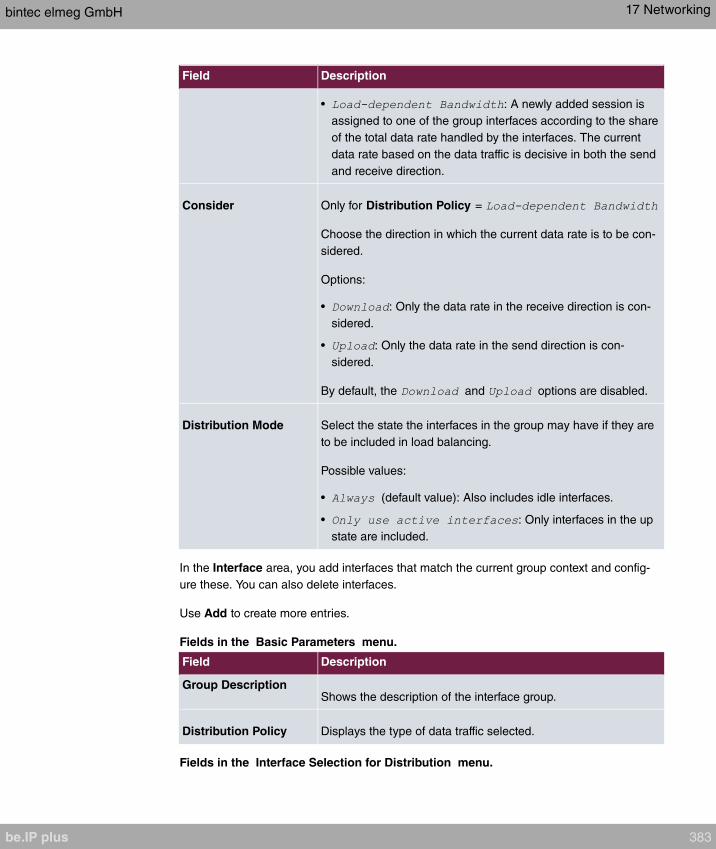
Field Description
• : A newly added session is
assigned to one of the group interfaces according to the share
of the total data rate handled by the interfaces. The current
data rate based on the data traffic is decisive in both the send
and receive direction.
Consider Only for Distribution Policy =
Choose the direction in which the current data rate is to be con-
sidered.
Options:
• : Only the data rate in the receive direction is con-
sidered.
• : Only the data rate in the send direction is con-
sidered.
By default, the and options are disabled.
Distribution Mode Select the state the interfaces in the group may have if they are
to be included in load balancing.
Possible values:
• (default value): Also includes idle interfaces.
• : Only interfaces in the up
state are included.
In the Interface area, you add interfaces that match the current group context and config-
ure these. You can also delete interfaces.
Use Add to create more entries.
Fields in the Basic Parameters menu.
Field Description
Group DescriptionShows the description of the interface group.
Distribution Policy Displays the type of data traffic selected.
Fields in the Interface Selection for Distribution menu.
bintec elmeg GmbH 17 Networking
be.IP plus 383

Field Description
Interface Select the interfaces that are to belong to the group from the
available interfaces.
Distribution Ratio Enter the percentage of the data traffic to be assigned to an in-
terface.
The meaning differs according to the Distribution Ratio em-
ployed:
• For
is based on the number of distrib-
uted sessions.
• For , the data rate is the de-
cisive factor.
The menu Advanced Settings consists of the following fields:
Fields in the Advanced Settings menu.
Field Description
Route Selector The Route Selector parameter is an additional criterion to help
define a load balancing group more precisely. Here, routing in-
formation is added to the "interface" entry within a load balan-
cing group. The route selector is required in certain scenarios to
enable the IP sessions managed by the router to be balanced
uniquely for each load balancing group. The following rules ap-
ply when using the parameter:
• If an interface is only assigned to one load balancing group, it
is not necessary to configure the route selector.
• If an interface is assigned to multiple load balancing groups,
configuration of the route selector is essential.
• The route selector must be configured identically for all inter-
face entries within a load balancing group.
Select the Destination IP Address of the desired route.
You can choose between all routes and all extended routes.
Tracking IP Address You can use the Tracking IP Address parameter to have a
particular route monitored.
17 Networking bintec elmeg GmbH
384 be.IP plus
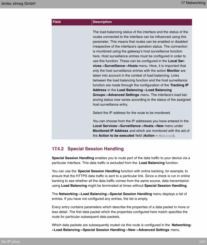
Field Description
The load balancing status of the interface and the status of the
routes connected to the interface can be influenced using this
parameter. This means that routes can be enabled or disabled
irrespective of the interface's operation status. The connection
is monitored using the gateway's host surveillance function
here. Host surveillance entries must be configured in order to
use this function. These can be configured in the Local Ser-
vices->Surveillance->Hosts menu. Here, it is important that
only the host surveillance entries with the action Monitor are
taken into account in the context of load balancing. Links
between the load balancing function and the host surveillance
function are made through the configuration of the Tracking IP
Address in the Load Balancing->Load Balancing
Groups->Advanced Settings menu. The interface's load bal-
ancing status now varies according to the status of the assigned
host surveillance entry.
Select the IP address for the route to be monitored.
You can choose from the IP addresses you have entered in the
Local Services->Surveillance->Hosts->New menu under
Monitored IP Address and which are monitored with the aid of
the Action to be executed field (Action = ).
17.4.2 Special Session Handling
Special Session Handling enables you to route part of the data traffic to your device via a
particular interface. This data traffic is excluded from the Load Balancing function.
You can use the Special Session Handling function with online banking, for example, to
ensure that the HTTPS data traffic is sent to a particular link. Since a check is run in online
banking to see whether all the data traffic comes from the same source, data transmission
using Load Balancing might be terminated at times without Special Session Handling.
The Networking->Load Balancing->Special Session Handling menu displays a list of
entries. If you have not configured any entries, the list is empty.
Every entry contains parameters which describe the properties of a data packet in more or
less detail. The first data packet which the properties configured here match specifies the
route for particular subsequent data packets.
Which data packets are subsequently routed via this route is configured in the Networking-
>Load Balancing->Special Session Handling->New->Advanced Settings menu.
bintec elmeg GmbH 17 Networking
be.IP plus 385

If in the Networking->Load Balancing->Special Session Handling->New menu, for ex-
ample, you select the parameter Service = (and leave the default value for
all the other parameters), the first HTTPS packet specifies the Destination Address and
the Destination Port (i. e. Port 443 with HTTPS) for data packets sent subsequently.
If, underFrozen Parameters , for the two parameters Destination Address and Destina-
tion Port you leave the default setting , the HTTPS packets with the same source
IP address as the first HTTPS packet are routed via port 443 to the same Destination Ad-
dress via the same interface as the first HTTPS packet.
17.4.2.1 Edit or New
Choose the icon to edit existing entries. Select the New button create new entries.
The Networking->Load Balancing->Special Session Handling->New menu consists of
the following fields:
Fields in the Basic Parameters menu.
Field Description
Admin Status Select whether the Special Session Handling should be activ-
ated.
The function is activated by selecting .
The function is enabled by default.
Description Enter a name for the entry.
Service Select one of the preconfigured services, if required. The ex-
tensive range of services configured ex works includes the fol-
lowing:
•
•
•
•
•
•
•
•
The default value is .
17 Networking bintec elmeg GmbH
386 be.IP plus

Field Description
Protocol Select a protocol, if required. The option (default value)
matches any protocol.
Destination IP Ad-
dress/Netmask
Enter, if required, the destination IP address and netmask of the
data packets.
Possible values:
• (default value)
• : Enter the IP address of the host.
• : Enter the network address and the related net-
mask.
Destination Port/Range Enter, if required, a destination port number or a range of des-
tination port numbers.
Possible values:
• (default value): The destination port is not specified.
• : Enter a destination port.
• : Enter a destination port range.
Source Interface If required, select your device's source interface.
Source IP Address/
Netmask
Enter, if required, the source IP address and netmask of the
data packets.
Possible values:
• (default value)
• : Enter the IP address of the host.
• : Enter the network address and the related net-
mask.
Source Port/Range Enter, if required, a source port number or a range of source
port numbers.
Possible values:
• (default value): The destination port is not specified.
• : Enter a destination port.
• : Enter a destination port range.
bintec elmeg GmbH 17 Networking
be.IP plus 387

Field Description
Special Handling Timer Enter the time period during which the specified data packets
are to be routed via the route that has been defined.
The default value is seconds.
The menu Advanced Settings consists of the following fields:
Fields in the Advanced Settings menu.
Field Description
Frozen Parameters Specify whether, when data packets are subsequently sent, the
two parameters Destination Address and Destination Port
must have the same value as the first data packet, i. e. whether
the subsequent data packets must be routed via the same Des-
tination Port to the same Destination Address.
The two parameters Destination Address and Destination
Port are enabled by default.
If you leave the default setting for one or both para-
meters, the value of the parameter concerned must be the
same as in the first data packet with data packets sent sub-
sequently.
You can disable one or both parameters if you wish.
The Source IP Address parameter must always have the same
value in data packets sent subsequently as it did in the first data
packet. So it cannot be disabled.
17.4.3 Load balancing - Configuration example
Requirements
• Gateway with the ADSL modem integrated
• An external ADSL modem
• Two independent ADSL Internet connections
Example scenario
17 Networking bintec elmeg GmbH
388 be.IP plus
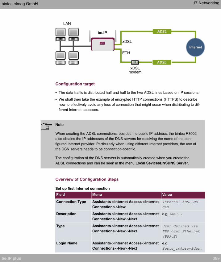
Configuration target
• The data traffic is distributed half and half to the two ADSL lines based on IP sessions.
• We shall then take the example of encrypted HTTP connections (HTTPS) to describe
how to effectively avoid any loss of connection that might occur when distributing to dif-
ferent Internet accesses.
Note
When creating the ADSL connections, besides the public IP address, the bintec R3002
also obtains the IP addresses of the DNS servers for resolving the name of the con-
figured Internet provider. Particularly when using different Internet providers, the use of
the DSN servers needs to be connection-specific.
The configuration of the DNS servers is automatically created when you create the
ADSL connections and can be seen in the menu Local SevicesDNSDNS Server.
Overview of Configuration Steps
Set up first Internet connection
Field Menu Value
Connection Type Assistants->Internet Access->Internet
Connections->New
Description Assistants->Internet Access->Internet
Connections->New->Next
e.g.
Type Assistants->Internet Access->Internet
Connections->New->Next
Login Name Assistants->Internet Access->Internet
Connections->New->Next
e.g.
bintec elmeg GmbH 17 Networking
be.IP plus 389

Field Menu Value
Password Assistants->Internet Access->Internet
Connections->New->Next
e.g.
Note
The message you get when you create the second ADSL connection may be ignored.
The IP load distribution avoids routing conflicts due to multiple standard routes!
Set up the second Internet connection
Field Menu Value
Connection Type Assistants->Internet Access->Internet
Connections->New
Description Assistants->Internet Access->Internet
Connections->New->Next
e.g.
Physical Ethernet
Port
Assistants->Internet Access->Internet
Connections->New->Next
e.g.
Type Assistants->Internet Access->Internet
Connections->New->Next
Login Name Assistants->Internet Access->Internet
Connections->New->Next
e.g.
Password Assistants->Internet Access->Internet
Connections->New->Next
e.g.
Create a load balancing group
Field Menu Value
Group Description Network->Load Balancing->Load Bal-
ancing Groups->New
e.g.
Distribution Policy Network->Load Balancing->Load Bal-
ancing Groups->New
Distribution Mode Network->Load Balancing->Load Bal-
ancing Groups->New
Interface Network->Load Balancing->Load Bal-
ancing Groups->New->Add
Distribution Ratio Network->Load Balancing->Load Bal-
ancing Groups->New->Add
Interface Network->Load Balancing->Load Bal-
17 Networking bintec elmeg GmbH
390 be.IP plus

Field Menu Value
ancing Groups->New->Add
Distribution Ratio Network->Load Balancing->Load Bal-
ancing Groups->New->Add
Special Session Handling
Field Menu Value
Description Network->Load Balancing->Special
Session Handling->New
e.g.
Service Network->Load Balancing->Special
Session Handling->New
Special Handling
Timer
Network->Load Balancing->Special
Session Handling->New
seconds
17.5 QoS
QoS (Quality of Service) makes it possible to distribute the available bandwidths effectively
and intelligently. Certain applications can be given preference and bandwidth reserved for
them. This is an advantage, especially for time-critical applications such as VoIP.
The QoS configuration consists of three parts:
• Creating IP filters
• Classifying data
• Prioritising data
17.5.1 IPv4/IPv6 Filter
In the Networking->IPv4/IPv6 Filter->QoS Filter menu IP filters are configured.
The list also displays any configured entries from Networking->Access Rules->Rule
Chains.
17.5.1.1 New
Choose the New button to define more IP filters.
The Networking->IPv4/IPv6 Filter->QoS Filter->New menu consists of the following
fields:
Fields in the Basic Parameters menu.
bintec elmeg GmbH 17 Networking
be.IP plus 391
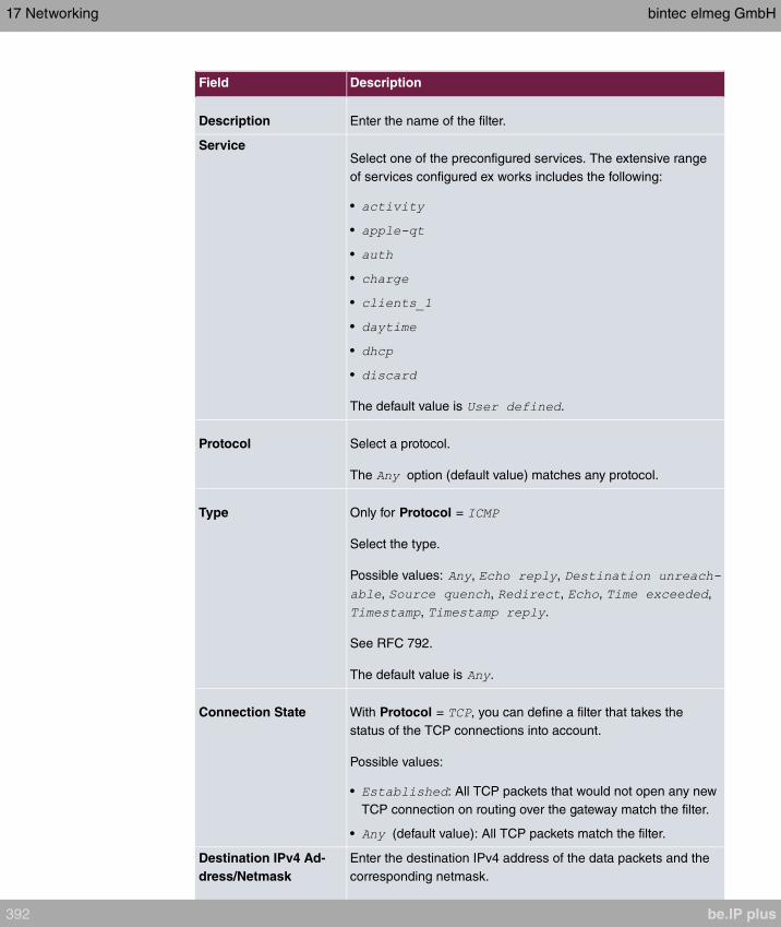
Field Description
Description Enter the name of the filter.
ServiceSelect one of the preconfigured services. The extensive range
of services configured ex works includes the following:
•
•
•
•
•
•
•
•
The default value is .
Protocol Select a protocol.
The option (default value) matches any protocol.
Type Only for Protocol =
Select the type.
Possible values: , ,
, , , , ,
, .
See RFC 792.
The default value is .
Connection State With Protocol = , you can define a filter that takes the
status of the TCP connections into account.
Possible values:
• : All TCP packets that would not open any new
TCP connection on routing over the gateway match the filter.
• (default value): All TCP packets match the filter.
Destination IPv4 Ad-
dress/Netmask
Enter the destination IPv4 address of the data packets and the
corresponding netmask.
17 Networking bintec elmeg GmbH
392 be.IP plus

Field Description
Possible values:
• (default value): The destination IP address/netmask are
not specified.
• : Enter the destination IP address of the host.
• : Enter the destination network address and the cor-
responding netmask.
Destination IPv6 Ad-
dress/Length
Enter the destination IPv6 address of the data packets and the
prefix length.
Possible values:
• (default value): The destination IP address/length are
not specified.
• : Enter the destination IP address of the host.
• : Enter the destination network address and the pre-
fix length.
Destination Port/Range Only for Protocol = , or
Enter a destination port number or a range of destination port
numbers.
Possible values:
• (default value): The destination port is not specified.
• : Enter a destination port.
• : Enter a destination port range.
Source IPv4 Address/
Netmask
Enter the source IPv4 address of the data packets and the cor-
responding netmask.
Possible values:
• (default value): The source IP address/netmask are not
specified.
• : Enter the source IP address of the host.
• : Enter the source network address and the corres-
ponding netmask.
Source IPv6 Address/
Length
Enter the source IPv6 address of the data packets and the pre-
fix length.
Possible values:
bintec elmeg GmbH 17 Networking
be.IP plus 393
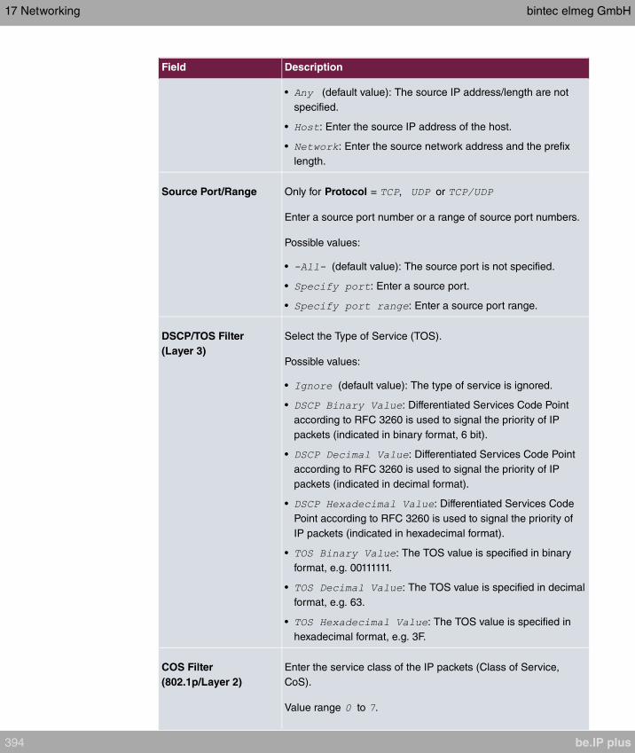
Field Description
• (default value): The source IP address/length are not
specified.
• : Enter the source IP address of the host.
• : Enter the source network address and the prefix
length.
Source Port/Range Only for Protocol = , or
Enter a source port number or a range of source port numbers.
Possible values:
• (default value): The source port is not specified.
• : Enter a source port.
• : Enter a source port range.
DSCP/TOS Filter
(Layer 3)
Select the Type of Service (TOS).
Possible values:
• (default value): The type of service is ignored.
• : Differentiated Services Code Point
according to RFC 3260 is used to signal the priority of IP
packets (indicated in binary format, 6 bit).
• : Differentiated Services Code Point
according to RFC 3260 is used to signal the priority of IP
packets (indicated in decimal format).
• : Differentiated Services Code
Point according to RFC 3260 is used to signal the priority of
IP packets (indicated in hexadecimal format).
• : The TOS value is specified in binary
format, e.g. 00111111.
• : The TOS value is specified in decimal
format, e.g. 63.
• : The TOS value is specified in
hexadecimal format, e.g. 3F.
COS Filter
(802.1p/Layer 2)
Enter the service class of the IP packets (Class of Service,
CoS).
Value range to .
17 Networking bintec elmeg GmbH
394 be.IP plus
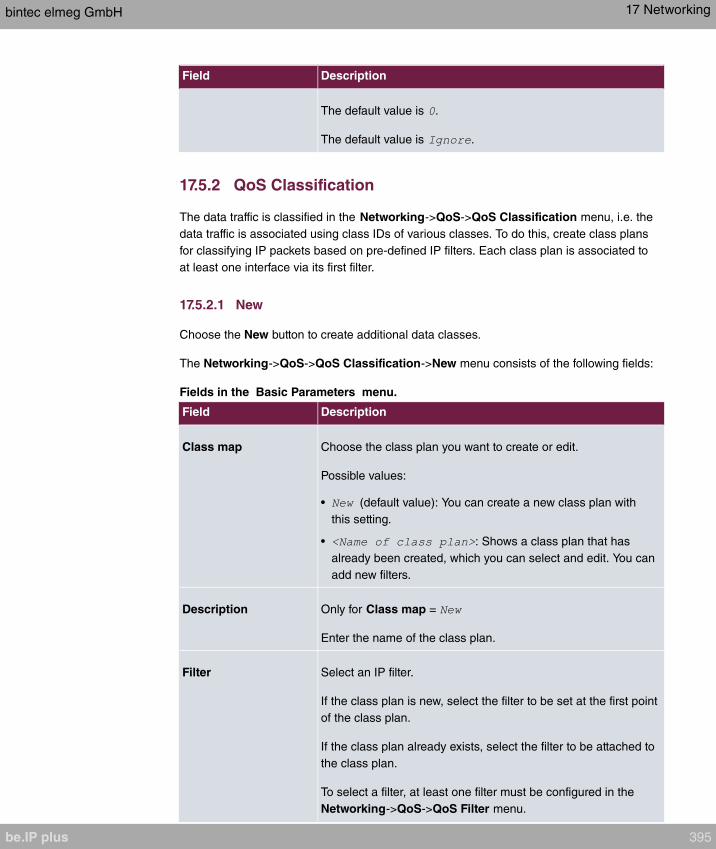
Field Description
The default value is .
The default value is .
17.5.2 QoS Classification
The data traffic is classified in the Networking->QoS->QoS Classification menu, i.e. the
data traffic is associated using class IDs of various classes. To do this, create class plans
for classifying IP packets based on pre-defined IP filters. Each class plan is associated to
at least one interface via its first filter.
17.5.2.1 New
Choose the New button to create additional data classes.
The Networking->QoS->QoS Classification->New menu consists of the following fields:
Fields in the Basic Parameters menu.
Field Description
Class map Choose the class plan you want to create or edit.
Possible values:
• (default value): You can create a new class plan with
this setting.
• : Shows a class plan that has
already been created, which you can select and edit. You can
add new filters.
Description Only for Class map =
Enter the name of the class plan.
Filter Select an IP filter.
If the class plan is new, select the filter to be set at the first point
of the class plan.
If the class plan already exists, select the filter to be attached to
the class plan.
To select a filter, at least one filter must be configured in the
Networking->QoS->QoS Filter menu.
bintec elmeg GmbH 17 Networking
be.IP plus 395

Field Description
Direction Select the direction of the data packets to be classified.
Possible values:
• : Incoming data packets are assigned to the class
(Class ID) that is then to be defined.
• (default value): Outgoing data packets are as-
signed to the class (Class ID) that is then to be defined.
• : Incoming and outgoing data packets are assigned to
the class (Class ID) that is then to be defined.
High Priority Class Enable or disable the high priority class. If the high priority class
is active, the data packets are associated with the class with the
highest priority and priority 0 is set automatically.
The function is enabled with .
The function is disabled by default.
Class ID Only for High Priority Class not active.
Choose a number which assigns the data packets to a class.
Note
The class ID is a label to assign data packets to specific
classes. (The class ID does not define the priority.)
Possible values are whole numbers between and .
Set DSCP/Traffic Class
Filter (Layer 3) Here you can set or change the DSCP/TOS value of the IP data
packets, based on the class (Class ID) that has been defined.
Possible values:
• (default value): The DSCP/TOS value of the IP
data packets remains unchanged.
• : Differentiated Services Code Point
according to RFC 3260 is used to signal the priority of IP
packets (indicated in binary format).
• : Differentiated Services Code Point
according to RFC 3260 is used to signal the priority of IP
17 Networking bintec elmeg GmbH
396 be.IP plus

Field Description
packets (indicated in decimal format).
• : Differentiated Services Code
Point according to RFC 3260 is used to signal the priority of
IP packets (indicated in hexadecimal format).
• : The TOS value is specified in binary
format, e.g. 00111111.
• : The TOS value is specified in decimal
format, e.g. 63.
• : The TOS value is specified in
hexadecimal format, e.g. 3F.
Set COS value
(802.1p/Layer 2) In the header of the Ethernet packets filtered by the selected fil-
ter, you can here set/change the service class (Layer 2 priority).
Possible values are whole numbers between and .
The default value is .
Interfaces Only for Class map =
When creating a new class plan, select the interfaces to which
you want to link the class plan. A class plan can be assigned to
multiple interfaces.
17.5.3 QoS Interfaces/Policies
In the Networking->QoS->QoS Interfaces/Policies menu, you set prioritisation of data.
Note
Data can only be prioritized in the outgoing direction.
Packets in the high-priority class always take priority over data with class IDs 1 - 254.
It is possible to assign or guarantee each queue and thus each data class a certain part of
the total bandwidth of the interface. In addition, you can optimise the transmission of voice
data (real time data).
Depending on the respective interface, a queue is created automatically for each class, but
only for data traffic classified as outgoing and for data traffic classified in both directions. A
priority is assigned to these automatic queues. The value of the priority is equal to the
bintec elmeg GmbH 17 Networking
be.IP plus 397

value of the class ID. You can change the default priority of a queue. If you add new
queues, you can also use classes in other class plans via the class ID.
17.5.3.1 New
Choose the New button to create additional prioritisations.
The Networking->QoS->QoS Interfaces/Policies->New menu consists of the following
fields:
Fields in the Basic Parameters menu.
Field Description
Interface Select the interface for which QoS is to be configured.
Prioritisation Al-
gorithm
Select the algorithm according to which the queues are to be
processed. This activates and deactivates QoS on the selected
interface.
Possible values:
• : QoS is activated on the interface. The
available bandwidth is distributed strictly according to the
queue priority.
• : QoS is activated on the interface.
The available bandwidth is distributed according to the
weighting (weight) of the queue. Exception: High-priority pack-
ets are always handled with priority.
• : QoS is activated on the inter-
face. The available bandwidth is distributed as “fairly” as pos-
sible among the (automatically detected) traffic flows in a
queue. Exception: High-priority packets are always handled
with priority.
• (default value): QoS is deactivated on the inter-
face. The existing configuration is not deleted, but can be ac-
tivated again if required.
Traffic shaping Activate or deactivate data rate limiting in the send direction.
The function is enabled with .
The function is disabled by default.
Maximum Upload Only for Traffic shaping = enabled.
17 Networking bintec elmeg GmbH
398 be.IP plus

Field Description
Speed Enter a maximum data rate for the selected interface in the
send direction in kbit per second.
Possible values are to .
The default value is , i.e. no limits are set, the selected inter-
face can occupy its maximum bandwidth.
Protocol Header Size
below Layer 3
Only for Traffic shaping = enabled.
Choose the interface type to include the size of the respective
overheads of a datagram when calculating the bandwidth.
Possible values:
• : Value in byte.
Possible values are to .
• (default
value)
Can only be selected for Ethernet interfaces
•
•
•
•
Can only be selected for IPSec interfaces:
•
•
•
•
Encryption Method Only if an IPSec Peers is selected as Interface, Traffic shap-
ing is and Protocol Header Size below Layer 3 is
not .
Select the encryption method used for the IPSec connection.
The encryption algorithm determines the length of the block
cipher which is taken into account during bandwidth calculation.
Possible values:
bintec elmeg GmbH 17 Networking
be.IP plus 399

Field Description
•
• AES128, AES192, AES256, Twofish - (cipher block size =
128 Bit)
Real Time Jitter Con-
trol
Only for Traffic shaping = enabled
Real Time Jitter Control optimises latency when forwarding real
time datagrams. The function ensures that large data packets
are fragmented according to the available upload bandwidth.
Real Time Jitter Control is useful for small upload bandwidths (<
800 kbps).
Activate or deactivate Real Time Jitter Control.
The function is enabled with .
The function is disabled by default.
Control Mode Only for Real Time Jitter Control = enabled.
Select the mode for optimising voice transmission.
Possible values:
• : All RTP streams are optimised. The
function activates the RTP stream detection mechanism for
the automatic detection of RTP streams. In this mode, the
Real Time Jitter Control is activated as soon as an RTP
stream has been detected.
• : Voice data transmission is not optimised.
• : This mode is used if
either the VoIP Application Layer Gateway (ALG) or the VoIP
Media Gateway (MGW) is active. Real Time Jitter Control is
activated by the control instances ALG or MGW.
• : Real Time Jitter Control is always active, even if no
real time data is routed.
Queues/Policies Configure the desired QoS queues.
For each class created from the class plan, which is associated
with the selected interface, a queue is generated automatically
and displayed here (only for data traffic classified as outgoing
17 Networking bintec elmeg GmbH
400 be.IP plus
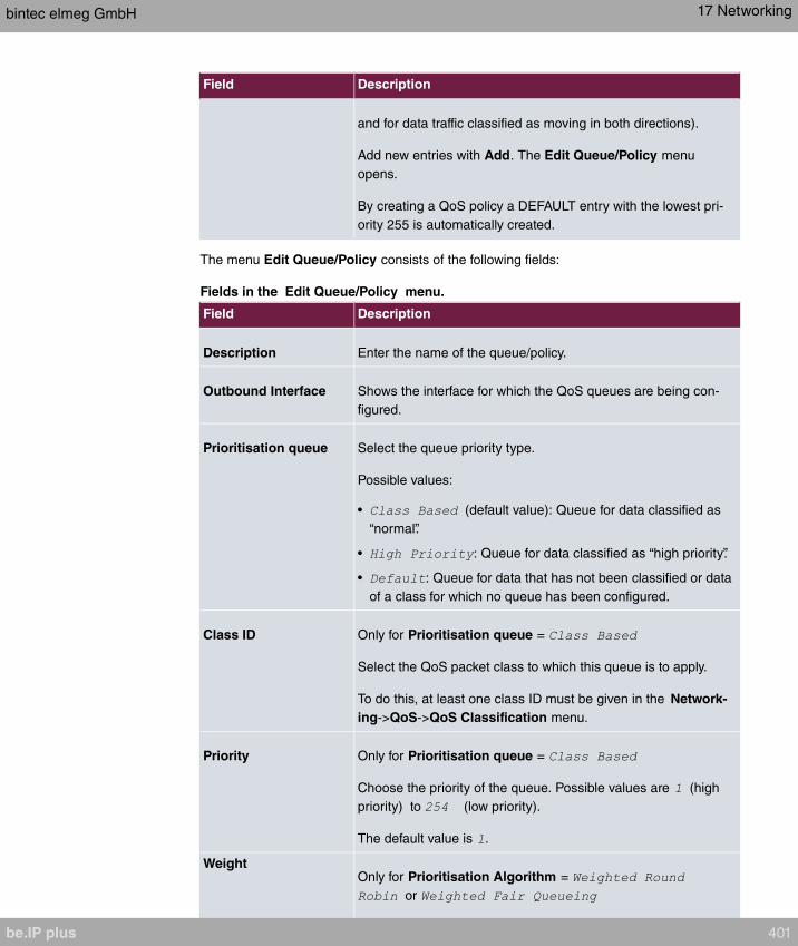
Field Description
and for data traffic classified as moving in both directions).
Add new entries with Add. The Edit Queue/Policy menu
opens.
By creating a QoS policy a DEFAULT entry with the lowest pri-
ority 255 is automatically created.
The menu Edit Queue/Policy consists of the following fields:
Fields in the Edit Queue/Policy menu.
Field Description
Description Enter the name of the queue/policy.
Outbound Interface Shows the interface for which the QoS queues are being con-
figured.
Prioritisation queue Select the queue priority type.
Possible values:
• (default value): Queue for data classified as
“normal”.
• : Queue for data classified as “high priority”.
• : Queue for data that has not been classified or data
of a class for which no queue has been configured.
Class ID Only for Prioritisation queue =
Select the QoS packet class to which this queue is to apply.
To do this, at least one class ID must be given in the Network-
ing->QoS->QoS Classification menu.
Priority Only for Prioritisation queue =
Choose the priority of the queue. Possible values are (high
priority) to (low priority).
The default value is .
WeightOnly for Prioritisation Algorithm =
or
bintec elmeg GmbH 17 Networking
be.IP plus 401

Field Description
Choose the priority of the queue. Possible values are to .
The default value is .
RTT Mode (Realtime
Traffic Mode)
Active or deactivate the real time transmission of the data.
The function is enabled with .
The function is disabled by default.
RTT mode should be activated for QoS classes in which real
time data has priority. This mode improves latency when for-
warding real time datagrams.
It is possible to configure multiple queues when RTT mode is
enabled. Queues with enabled RTT mode must always have a
higher priority than queues with disabled RTT mode.
Traffic Shaping Activate or deactivate data rate (=Traffic Shaping) limiting in the
send direction.
The data rate limit applies to the selected queue. (This is not the
limit that can be defined on the interface.)
The function is enabled with .
The function is disabled by default.
Maximum Upload
Speed
Only for Traffic Shaping = enabled.
Enter a maximum data rate for the queue in kbits.
Possible values are to .
The default value is .
Overbooking allowed Only for Traffic Shaping = enabled.
Enable or disable the function. The function controls the band-
width limit.
If Overbooking allowed is activated, the bandwidth limit set for
this queue can be exceeded, as long as free bandwidth exists
on the interface.
If Overbooking allowed is deactivated, the queue can never
17 Networking bintec elmeg GmbH
402 be.IP plus
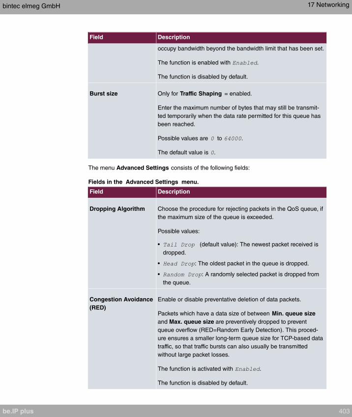
Field Description
occupy bandwidth beyond the bandwidth limit that has been set.
The function is enabled with .
The function is disabled by default.
Burst size Only for Traffic Shaping = enabled.
Enter the maximum number of bytes that may still be transmit-
ted temporarily when the data rate permitted for this queue has
been reached.
Possible values are to .
The default value is .
The menu Advanced Settings consists of the following fields:
Fields in the Advanced Settings menu.
Field Description
Dropping Algorithm Choose the procedure for rejecting packets in the QoS queue, if
the maximum size of the queue is exceeded.
Possible values:
• (default value): The newest packet received is
dropped.
• : The oldest packet in the queue is dropped.
• : A randomly selected packet is dropped from
the queue.
Congestion Avoidance
(RED)
Enable or disable preventative deletion of data packets.
Packets which have a data size of between Min. queue size
and Max. queue size are preventively dropped to prevent
queue overflow (RED=Random Early Detection). This proced-
ure ensures a smaller long-term queue size for TCP-based data
traffic, so that traffic bursts can also usually be transmitted
without large packet losses.
The function is activated with .
The function is disabled by default.
bintec elmeg GmbH 17 Networking
be.IP plus 403
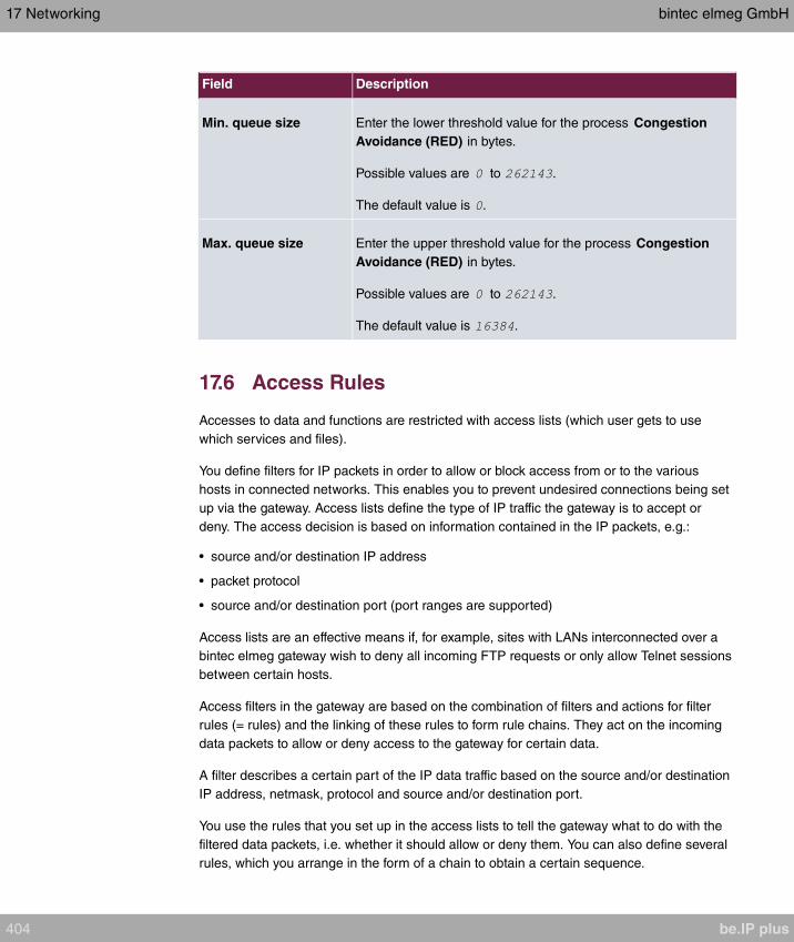
Field Description
Min. queue size Enter the lower threshold value for the process Congestion
Avoidance (RED) in bytes.
Possible values are to .
The default value is .
Max. queue size Enter the upper threshold value for the process Congestion
Avoidance (RED) in bytes.
Possible values are to .
The default value is .
17.6 Access Rules
Accesses to data and functions are restricted with access lists (which user gets to use
which services and files).
You define filters for IP packets in order to allow or block access from or to the various
hosts in connected networks. This enables you to prevent undesired connections being set
up via the gateway. Access lists define the type of IP traffic the gateway is to accept or
deny. The access decision is based on information contained in the IP packets, e.g.:
• source and/or destination IP address
• packet protocol
• source and/or destination port (port ranges are supported)
Access lists are an effective means if, for example, sites with LANs interconnected over a
bintec elmeg gateway wish to deny all incoming FTP requests or only allow Telnet sessions
between certain hosts.
Access filters in the gateway are based on the combination of filters and actions for filter
rules (= rules) and the linking of these rules to form rule chains. They act on the incoming
data packets to allow or deny access to the gateway for certain data.
A filter describes a certain part of the IP data traffic based on the source and/or destination
IP address, netmask, protocol and source and/or destination port.
You use the rules that you set up in the access lists to tell the gateway what to do with the
filtered data packets, i.e. whether it should allow or deny them. You can also define several
rules, which you arrange in the form of a chain to obtain a certain sequence.
17 Networking bintec elmeg GmbH
404 be.IP plus
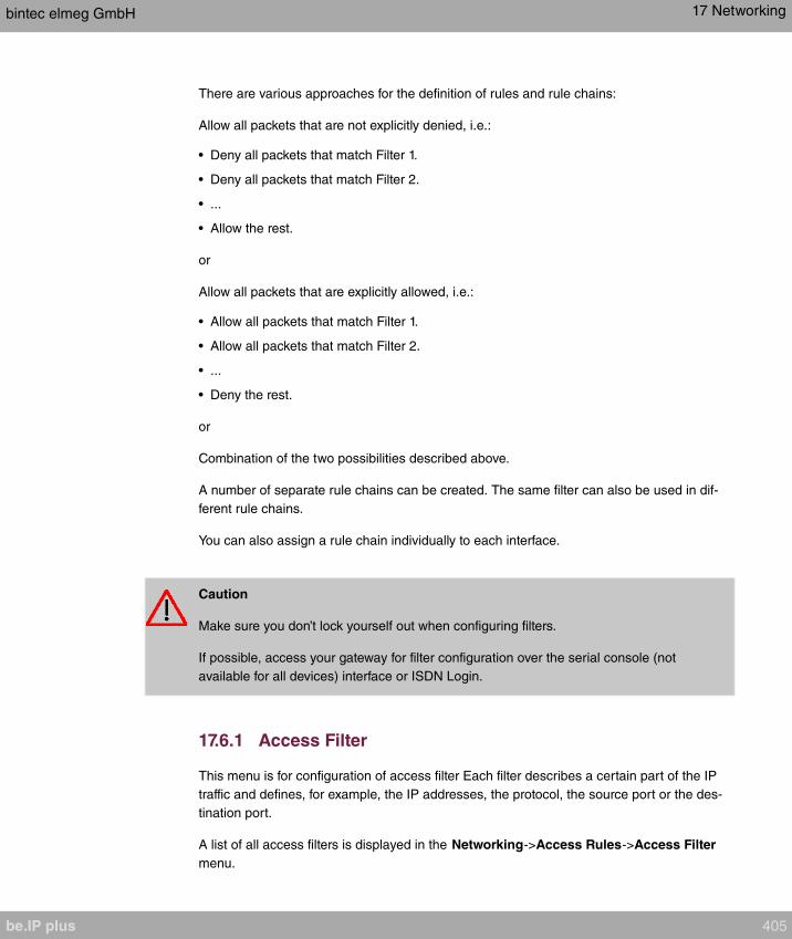
There are various approaches for the definition of rules and rule chains:
Allow all packets that are not explicitly denied, i.e.:
• Deny all packets that match Filter 1.
• Deny all packets that match Filter 2.
• ...
• Allow the rest.
or
Allow all packets that are explicitly allowed, i.e.:
• Allow all packets that match Filter 1.
• Allow all packets that match Filter 2.
• ...
• Deny the rest.
or
Combination of the two possibilities described above.
A number of separate rule chains can be created. The same filter can also be used in dif-
ferent rule chains.
You can also assign a rule chain individually to each interface.
Caution
Make sure you don’t lock yourself out when configuring filters.
If possible, access your gateway for filter configuration over the serial console (not
available for all devices) interface or ISDN Login.
17.6.1 Access Filter
This menu is for configuration of access filter Each filter describes a certain part of the IP
traffic and defines, for example, the IP addresses, the protocol, the source port or the des-
tination port.
A list of all access filters is displayed in the Networking->Access Rules->Access Filter
menu.
bintec elmeg GmbH 17 Networking
be.IP plus 405

17.6.1.1 Edit or New
Choose the icon to edit existing entries. To configure access fitters, select the New but-
ton.
The Networking->Access Rules->Access Filter->New menu consists of the following
fields:
Fields in the Basic Parameters menu.
Field Description
Description Enter a description for the filter.
ServiceSelect one of the preconfigured services. The extensive range
of services configured ex works includes the following:
•
•
•
•
•
•
•
•
The default value is .
Protocol Select a protocol.
The option (default value) matches any protocol.
TypeOnly if Protocol =
Possible values:
•
•
•
•
•
•
•
17 Networking bintec elmeg GmbH
406 be.IP plus
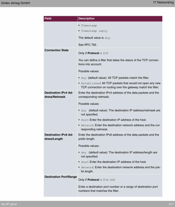
Field Description
•
•
The default value is .
See RFC 792.
Connection StateOnly if Protocol =
You can define a filter that takes the status of the TCP connec-
tions into account.
Possible values:
• (default value): All TCP packets match the filter.
• : All TCP packets that would not open any new
TCP connection on routing over the gateway match the filter.
Destination IPv4 Ad-
dress/Netmask
Enter the destination IPv4 address of the data packets and the
corresponding netmask.
Possible values:
• (default value): The destination IP address/netmask are
not specified.
• : Enter the destination IP address of the host.
• : Enter the destination network address and the cor-
responding netmask.
Destination IPv6 Ad-
dress/Length
Enter the destination IPv6 address of the data packets and the
prefix length.
Possible values:
• (default value): The destination IP address/length are
not specified.
• : Enter the destination IP address of the host.
• : Enter the destination network address and the pre-
fix length.
Destination Port/RangeOnly if Protocol = ,
Enter a destination port number or a range of destination port
numbers that matches the filter.
bintec elmeg GmbH 17 Networking
be.IP plus 407
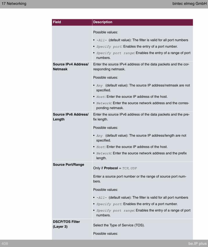
Field Description
Possible values:
• (default value): The filter is valid for all port numbers
• : Enables the entry of a port number.
• : Enables the entry of a range of port
numbers.
Source IPv4 Address/
Netmask
Enter the source IPv4 address of the data packets and the cor-
responding netmask.
Possible values:
• (default value): The source IP address/netmask are not
specified.
• : Enter the source IP address of the host.
• : Enter the source network address and the corres-
ponding netmask.
Source IPv6 Address/
Length
Enter the source IPv6 address of the data packets and the pre-
fix length.
Possible values:
• (default value): The source IP address/length are not
specified.
• : Enter the source IP address of the host.
• : Enter the source network address and the prefix
length.
Source Port/RangeOnly if Protocol = ,
Enter a source port number or the range of source port num-
bers.
Possible values:
• (default value): The filter is valid for all port numbers
• : Enables the entry of a port number.
• : Enables the entry of a range of port
numbers.
DSCP/TOS Filter
(Layer 3) Select the Type of Service (TOS).
Possible values:
17 Networking bintec elmeg GmbH
408 be.IP plus

Field Description
• (default value): The type of service is ignored.
• : Differentiated Services Code Point
according to RFC 3260 is used to signal the priority of IP
packets (indicated in binary format, 6 bit).
• : Differentiated Services Code Point
according to RFC 3260 is used to signal the priority of IP
packets (indicated in decimal format).
• : Differentiated Services Code
Point according to RFC 3260 is used to signal the priority of
IP packets (indicated in hexadecimal format).
• : The TOS value is specified in binary
format, e.g. 00111111.
• : The TOS value is specified in decimal
format, e.g. 63.
• : The TOS value is specified in
hexadecimal format, e.g. 3F.
COS Filter
(802.1p/Layer 2) Enter the service class of the IP packets (Class of Service,
CoS).
Possible values are whole numbers between and .
The default value is .
17.6.2 Rule Chains
Rules for IP filters are configured in the Rule Chains menu. These can be created separ-
ately or incorporated in rule chains.
In the Networking->Access Rules->Rule Chains menu, all created filter rules are listed.
17.6.2.1 Edit or New
Choose the icon to edit existing entries. To configure access lists, select the New but-
ton.
The Networking->Access Rules->Rule Chains->New menu consists of the following
fields:
Fields in the Basic Parameters menu.
bintec elmeg GmbH 17 Networking
be.IP plus 409

Field Description
Rule ChainSelect whether to create a new rule chain or to edit an existing
one.
Possible values:
• (default value): You can create a new rule chain with this
setting.
• : Select an already existing
rule chain, and thus add another rule to it.
Description Enter the name of the rule chain.
Access FilterSelect an IP filter.
If the rule chain is new, select the filter to be set at the first point
of the rule chain.
If the rule chain already exists, select the filter to be attached to
the rule chain.
ActionDefine the action to be taken for a filtered data packet.
Possible values:
• (default value): Allow packet
if it matches the filter.
• : Allow packet if it
does not match the filter.
• : Deny packet if it matches the
filter.
• : Deny packet if it does
not match the filter.
• : Use next rule.
To set the rules of a rule chain in a different order select the button in the list menu for
the entry to be shifted. A dialog box opens, in which you can decide under Move whether
the entry (default value) or another rule of this rule chain is to be shifted.
17.6.3 Interface Assignment
In this menu, the configured rule chains are assigned to the individual interfaces and the
gateway’s behavior is defined for denying IP packets.
17 Networking bintec elmeg GmbH
410 be.IP plus

A list of all configured interface assignments is displayed in the Networking->Access
Rules->Interface Assignment menu.
17.6.3.1 Edit or New
Choose the icon to edit existing entries. Choose the New button to configure additional
assignments.
The Networking->Access Rules->Interface Assignment->New menu consists of the fol-
lowing fields:
Fields in the Basic Parameters menu.
Field Description
Interface Select the interface for which a configured rule chain is to be as-
signed.
Rule Chain Select a rule chain.
Silent DenyDefine whether the sender is to be informed if an IP packet is
denied.
• (default value): The sender is not informed.
• : The sender receives an ICMP message.
Reporting MethodDefine whether a syslog message is to be generated if a packet
is denied.
Possible values:
• : No syslog message.
• (default value): A syslog message is generated with the
protocol number, source IP address and source port number.
• : A syslog message is generated with the contents of the
first 64 bytes of the denied packet.
bintec elmeg GmbH 17 Networking
be.IP plus 411

Chapter 18 Multicast
What is multicasting?
Many new communication technologies are based on communication from one sender to
several recipients. Therefore, modern telecommunication systems such as voice over IP or
video and audio streaming (e.g. IPTV or Webradio) focus on reducing data traffic, e.g. by
offering TriplePlay (voice, video, data). Multicast is a cost-effective solution for effective use
of bandwidth because the sender of the data packet, which can be received by several re-
cipients, only needs to send the packet once. The packet is sent to a virtual address
defined as a multicast group. Interested recipients log in to these groups.
Other areas of use
One classic area in which multicast is used is for conferences (audio/video) with several re-
cipients. The most well-known are probably the MBone Multimedia Audio Tool (VAT),
Video Conferencing Tool (VIC) and Whiteboard (WB). VAT can be used to hold audio con-
ferences. All subscribers are displayed in a window and the speaker(s) are indicated by a
black box. Other areas of use are of particular interest to companies. Here, multicasting
makes it possible to synchronise the databases of several servers, which is valuable for
multinationals or even companies with just a few locations.
Address range for multicast
For, IPv4 the IP addresses 224.0.0.0 to 239.255.255.255 (224.0.0.0/4) are reserved for
multicast in the class D network. An IP address from this range represents a multicast
group to which several recipients can log in. The multicast router then forwards the re-
quired packets to all subnets with logged in recipients.
Multicast basics
Multicast is connectionless, which means that any trouble-shooting or flow control needs to
be guaranteed at application level.
At transport level, UDP is used almost exclusively, as, in contrast to TCP, it is not based on
a point-to-point connection.
At IP level, the main difference is therefore that the destination address does not address a
18 Multicast bintec elmeg GmbH
412 be.IP plus

dedicated host, but rather a group, i.e. during the routing of multicast packets, the decisive
factor is whether a recipient is in a logged-in subnet.
In the local network, all hosts are required to accept all multicast packets. For Ethernet or
FDD, this is based on MAC mapping, where the group address is encoded into the destina-
tion MAC address. For routing between several networks, the routers first need to make
themselves known to all potential recipients in the subnet. This is achieved by means of
Membership Management protocols such as IGMP for IPv4 and MLP for IPv6.
Membership Management protocol
In IPv4, IGMP (Internet Group Management Protocol) is a protocol that hosts can use to
provide the router with multicast membership information. IP addresses of the class D ad-
dress range are used for addressing. An IP address in this class represents a group. A
sender (e.g. Internet radio) sends data to this group. The addresses (IP) of the various
senders within a group are called the source (addresses). Several senders (with different
IP addresses) can therefore transmit to the same multicast group, leading to a 1-to-n rela-
tionship between groups and source addresses. This information is forwarded to the router
by means of reports. In the case of incoming multicast data traffic, a router can use this in-
formation to decide whether a host in its subnet wants to receive it. Your device supports
the current version IGMP V3, which is upwardly compatible, which means that both V3 and
V1/V2 hosts can be managed.
Your device supports the following multicast mechanisms:
• Forwarding: This relates to static forwarding, i.e. incoming data traffic for a group is
passed in all cases. This is a useful option if multicast data traffic is to be permanently
passed.
• IGMP: IGMP is used to gather information about the potential recipients in a subnet. In
the case of a hop, incoming multicast data traffic can thus be selected.
Tip
With multicast, the focus is on excluding data traffic from unwanted multicast groups.
Note that if forwarding is combined with IGMP, the packets can be forwarded to the
groups specified in the forwarding request.
18.1 General
bintec elmeg GmbH 18 Multicast
be.IP plus 413

18.1.1 General
In the Multicast->General->General menu you can disable or enable the multicast func-
tion.
The menu consists of the following fields:
Fields in the Basic Settings menu.
Field Description
Multicast Routing Select whether Multicast Routing should be used.
The function is enabled with .
The function is disabled by default.
18.2 IGMP
IGMP (Internet Group Management Protocol, see RFC 3376) is used to signal the informa-
tion about group (membership) in a subnet. As a result, only the packets explicitly wanted
by a host enter the subnet.
Special mechanisms ensure that the requirements of the individual clients are taken into
consideration. At the moment there are three versions of IGMP (V1 - V3); most current sys-
tems use V3, and less often V2.
Two packet types play a central role in IGMP: queries and reports.
Queries are only transmitted from a router. If several IGMP routers exist in a network, the
router with the lowest IP address is the "querier". We differentiate here between a general
query (sent to 224.0.0.1), a group-specific query (sent to a group address) and the group-
and-source-specific query (sent to a specific group address). Reports are only sent by
hosts to respond to queries.
18.2.1 IGMP
In this menu, you configure the interfaces on which IGMP is to be enabled.
18.2.1.1 Edit or New
Choose the icon to edit existing entries. Choose the New button to configure IGMP on
other interfaces.
18 Multicast bintec elmeg GmbH
414 be.IP plus
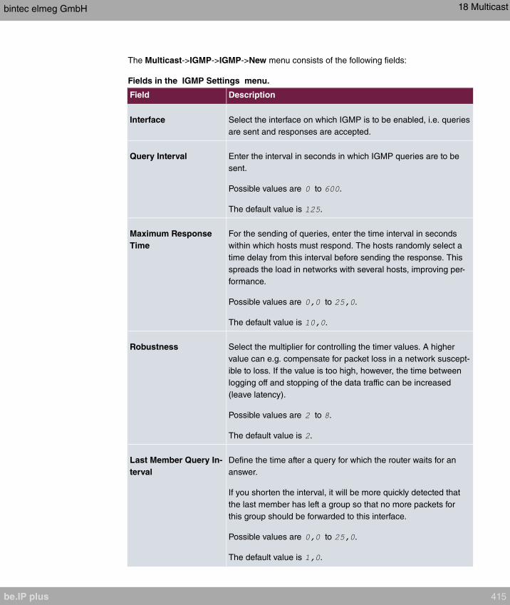
The Multicast->IGMP->IGMP->New menu consists of the following fields:
Fields in the IGMP Settings menu.
Field Description
Interface Select the interface on which IGMP is to be enabled, i.e. queries
are sent and responses are accepted.
Query Interval Enter the interval in seconds in which IGMP queries are to be
sent.
Possible values are to .
The default value is .
Maximum Response
Time
For the sending of queries, enter the time interval in seconds
within which hosts must respond. The hosts randomly select a
time delay from this interval before sending the response. This
spreads the load in networks with several hosts, improving per-
formance.
Possible values are to .
The default value is .
Robustness Select the multiplier for controlling the timer values. A higher
value can e.g. compensate for packet loss in a network suscept-
ible to loss. If the value is too high, however, the time between
logging off and stopping of the data traffic can be increased
(leave latency).
Possible values are to .
The default value is .
Last Member Query In-
terval
Define the time after a query for which the router waits for an
answer.
If you shorten the interval, it will be more quickly detected that
the last member has left a group so that no more packets for
this group should be forwarded to this interface.
Possible values are to .
The default value is .
bintec elmeg GmbH 18 Multicast
be.IP plus 415
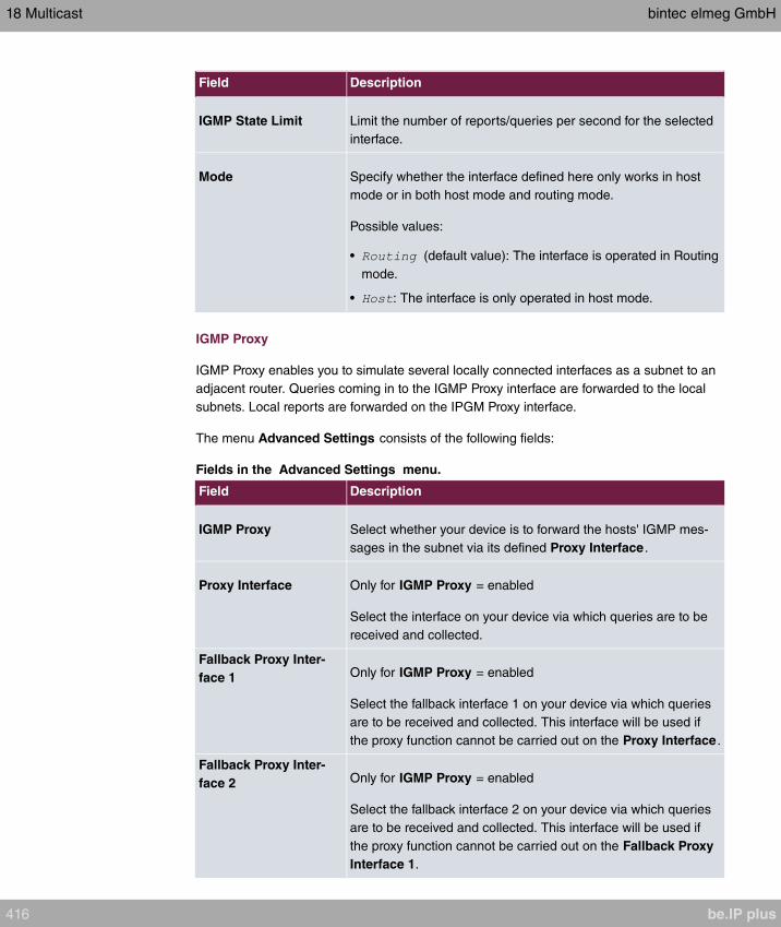
Field Description
IGMP State Limit Limit the number of reports/queries per second for the selected
interface.
Mode Specify whether the interface defined here only works in host
mode or in both host mode and routing mode.
Possible values:
• (default value): The interface is operated in Routing
mode.
• : The interface is only operated in host mode.
IGMP Proxy
IGMP Proxy enables you to simulate several locally connected interfaces as a subnet to an
adjacent router. Queries coming in to the IGMP Proxy interface are forwarded to the local
subnets. Local reports are forwarded on the IPGM Proxy interface.
The menu Advanced Settings consists of the following fields:
Fields in the Advanced Settings menu.
Field Description
IGMP Proxy Select whether your device is to forward the hosts' IGMP mes-
sages in the subnet via its defined Proxy Interface .
Proxy Interface Only for IGMP Proxy = enabled
Select the interface on your device via which queries are to be
received and collected.
Fallback Proxy Inter-
face 1 Only for IGMP Proxy = enabled
Select the fallback interface 1 on your device via which queries
are to be received and collected. This interface will be used if
the proxy function cannot be carried out on the Proxy Interface .
Fallback Proxy Inter-
face 2 Only for IGMP Proxy = enabled
Select the fallback interface 2 on your device via which queries
are to be received and collected. This interface will be used if
the proxy function cannot be carried out on the Fallback Proxy
Interface 1.
18 Multicast bintec elmeg GmbH
416 be.IP plus
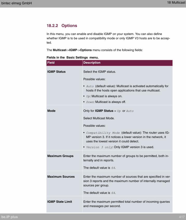
18.2.2 Options
In this menu, you can enable and disable IGMP on your system. You can also define
whether IGMP is to be used in compatibility mode or only IGMP V3 hosts are to be accep-
ted.
The Multicast->IGMP->Options menu consists of the following fields:
Fields in the Basic Settings menu.
Field Description
IGMP Status Select the IGMP status.
Possible values:
• (default value): Multicast is activated automatically for
hosts if the hosts open applications that use multicast.
• : Multicast is always on.
• : Multicast is always off.
Mode Only for IGMP Status = or
Select Multicast Mode.
Possible values:
• (default value): The router uses IG-
MP version 3. If it notices a lower version in the network, it
uses the lowest version it could detect.
• : Only IGMP version 3 is used.
Maximum Groups Enter the maximum number of groups to be permitted, both in-
ternally and in reports.
The default value is .
Maximum Sources Enter the maximum number of sources that are specified in ver-
sion 3 reports and the maximum number of internally managed
sources per group.
The default value is .
IGMP State Limit Enter the maximum permitted total number of incoming queries
and messages per second.
bintec elmeg GmbH 18 Multicast
be.IP plus 417

Field Description
The default value is , i.e. the number of IGMP status mes-
sages is not limited.
The section Advanced Settings allows you to switch IGMP Snooping on or off. IGMP
Snooping ensures that multicast traffic is sent only to those clients that have actually re-
quired a specific multicast stream.
The function is enabled by default.
18.3 Forwarding
18.3.1 Forwarding
In this menu, you specify which multicast groups are always passed between the interfaces
of your device.
18.3.1.1 New
Choose the New button to create forwarding rules for new multicast groups.
The Multicast->Forwarding->Forwarding->New menu consists of the following fields:
Fields in the Basic Parameters menu.
Field Description
All Multicast Groups Select whether all multicast groups, i.e. the complete multicast
address range 224.0.0.0/4, are to be forwarded from the defined
Source Interface to the defined Destination Interface. To do
this, check
Disable the option if you only want to forward one defined mul-
ticast group to a particular interface.
The option is deactivated by default.
Multicast Group Ad-
dress
Only for All Multicast Groups = not active.
Enter here the address of the multicast group you want to for-
ward from a defined Source Interface to a defined Destination
Interface.
Source Interface Select the interface on your device to which the selected multic-
18 Multicast bintec elmeg GmbH
418 be.IP plus

Field Description
ast group is sent.
Destination Interface Select the interface on your device to which the selected multic-
ast group is to be forwarded.
bintec elmeg GmbH 18 Multicast
be.IP plus 419
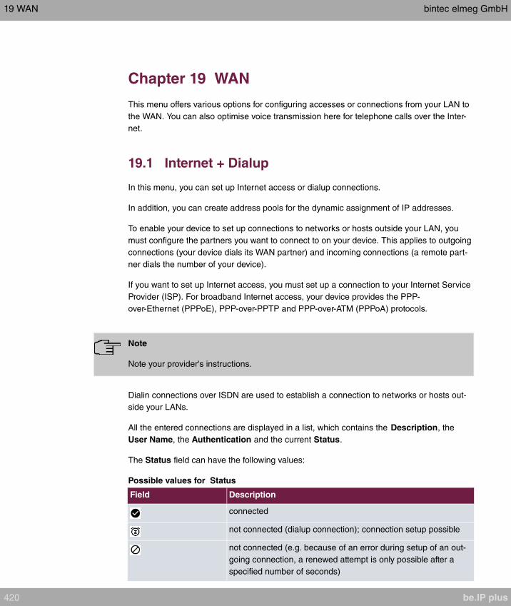
Chapter 19 WAN
This menu offers various options for configuring accesses or connections from your LAN to
the WAN. You can also optimise voice transmission here for telephone calls over the Inter-
net.
19.1 Internet + Dialup
In this menu, you can set up Internet access or dialup connections.
In addition, you can create address pools for the dynamic assignment of IP addresses.
To enable your device to set up connections to networks or hosts outside your LAN, you
must configure the partners you want to connect to on your device. This applies to outgoing
connections (your device dials its WAN partner) and incoming connections (a remote part-
ner dials the number of your device).
If you want to set up Internet access, you must set up a connection to your Internet Service
Provider (ISP). For broadband Internet access, your device provides the PPP-
over-Ethernet (PPPoE), PPP-over-PPTP and PPP-over-ATM (PPPoA) protocols.
Note
Note your provider's instructions.
Dialin connections over ISDN are used to establish a connection to networks or hosts out-
side your LANs.
All the entered connections are displayed in a list, which contains the Description, the
User Name, the Authentication and the current Status.
The Status field can have the following values:
Possible values for Status
Field Description
connected
not connected (dialup connection); connection setup possible
not connected (e.g. because of an error during setup of an out-
going connection, a renewed attempt is only possible after a
specified number of seconds)
19 WAN bintec elmeg GmbH
420 be.IP plus

Field Description
administratively set to down (deactivated); connection setup not
possible
19.1.1 PPPoE
A list of all PPToE interfaces is displayed in the WAN->Internet + Dialup->PPPoE menu.
PPP over Ethernet (PPPoE) is the use of the Point-to-Point Protocol (PPP) network pro-
tocol over an Ethernet connection. Today, PPPoE is used for ADSL connections in Ger-
many. In Austria, the Point To Point Tunnelling Protocol (PPTP) was originally used for AD-
SL access. However, PPPoE is now offered here too by some providers.
19.1.1.1 New
Choose the New button to set up new PPPoE interfaces.
The menu WAN->Internet + Dialup->PPPoE->New consists of the following fields:
Fields in the Basic Parameters menu.
Field Description
Description Enter a name to uniquely identify the PPPoE partner. The first
character in this field must not be a number No special charac-
ters or umlauts must be used.
PPPoE Mode Select whether you want to use a standard Internet connection
over PPPoE ( ) or your Internet access is to be set
up over several interfaces ( ). If you choose
, you can connect several DSL connections from a pro-
vider over PPP as a static bundle in order to obtain more band-
width. Each of these DSL connections should use a separate
Ethernet connection for this. At the moment, many providers are
still in the process of preparing the PPPoE Multilink function.
For PPPoE Multilink, we recommend using your device's Ether-
net switch in Split-Port mode and to use a separate Ethernet in-
terface e.g. , for each PPPoE connection.
If you also want to use an external modem for PPPoE Multilink,
you must run your device's Ethernet switch in Split-Port mode.
PPPoE Ethernet Inter-
face
Only for PPPoE Mode =
Select the Ethernet interface specified for a standard PPPoE
bintec elmeg GmbH 19 WAN
be.IP plus 421

Field Description
connection.
If you want to use an external DSL modem, select the Ethernet
port to which the modem is connected.
When using the internal DSL modem, select here the EthoA in-
terface configured in WAN->ATM->Profiles->New.
Select in order to enable the automatic VDSL/AD-
SL mode. In this mode, the interface for the Internet connection
is selected automatically. Note that there has to be an interface
entry in the ATM menu. This is not required for a VDSL connec-
tion.
PPPoE Interfaces for
Multilink
Only for PPPoE Mode =
Select the interfaces you want to use for your Internet connec-
tion. Click the Add button to create new entries.
User Name Enter the user name.
Password Enter the password.
VLAN Certain Internet service providers require a VLAN-ID. Activate
this function to be able to enter a value under VLAN ID.
VLAN IDOnly if VLAN is enabled.
Enter the VLAN-ID that you received from your provider.
Always on Select whether the interface should always be activated.
The function is enabled with .
The function is disabled by default.
Only activate this option if you have Internet access with a flat-
rate charge.
Connection Idle
Timeout
Only if Always on is disabled.
Enter the idle time in seconds for static short hold. The static
short hold setting determines how many seconds should pass
between sending the last traffic data packet and clearing the
connection.
19 WAN bintec elmeg GmbH
422 be.IP plus
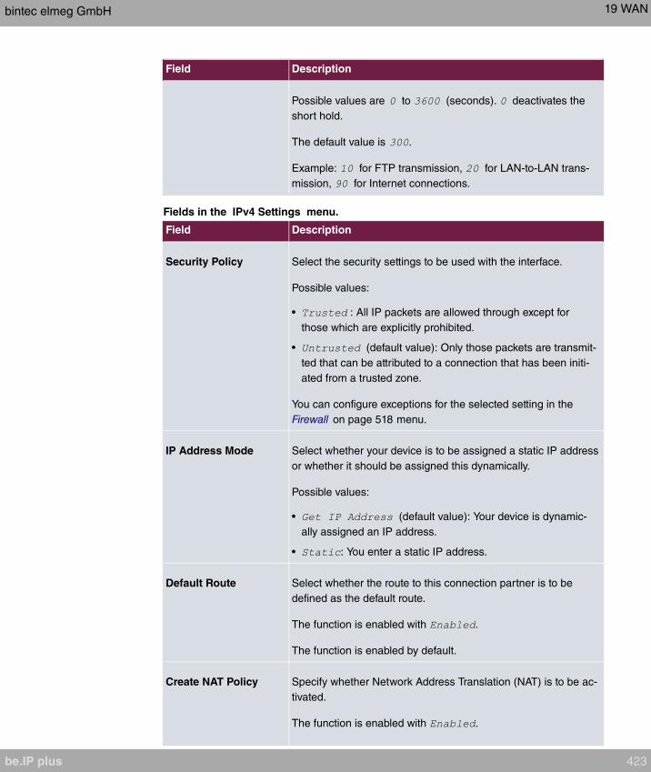
Field Description
Possible values are to (seconds). deactivates the
short hold.
The default value is .
Example: for FTP transmission, for LAN-to-LAN trans-
mission, for Internet connections.
Fields in the IPv4 Settings menu.
Field Description
Security Policy Select the security settings to be used with the interface.
Possible values:
• : All IP packets are allowed through except for
those which are explicitly prohibited.
• (default value): Only those packets are transmit-
ted that can be attributed to a connection that has been initi-
ated from a trusted zone.
You can configure exceptions for the selected setting in the
Firewall on page 518 menu.
IP Address Mode Select whether your device is to be assigned a static IP address
or whether it should be assigned this dynamically.
Possible values:
• (default value): Your device is dynamic-
ally assigned an IP address.
• : You enter a static IP address.
Default Route Select whether the route to this connection partner is to be
defined as the default route.
The function is enabled with .
The function is enabled by default.
Create NAT Policy Specify whether Network Address Translation (NAT) is to be ac-
tivated.
The function is enabled with .
bintec elmeg GmbH 19 WAN
be.IP plus 423

Field Description
The function is enabled by default.
Local IP Address Only if IP Address Mode =
Enter the static IP address of the connection partner.
Route Entries Only if IP Address Mode =
Define other routing entries for this connection partner.
Add new entries with Add.
• : IP address of the destination host or
network.
• : Netmask for Remote IP Address If no entry is
made, your device uses a default netmask.
• : The lower the value, the higher the priority of the
route (range of values ... ). The default value is .
Fields in the IPv6 Settings menu
Field Description
IPv6 Select whether the selected PPPoE interface should use Inter-
net Protocol version 6 (IPv6) for data transmission.
The function is activated by selecting .
The function is disabled by default.
Security Policy Select the security settings to be used with the interface.
Possible values:
• (default value): Only those packets are transmit-
ted that can be attributed to a connection that has been initi-
ated from a trusted zone.
We recommend you use this setting if you want to use IPv6
outside of your LAN.
• : All IP packets are allowed through except for those
which are explicitly prohibited.
We recommend you use this setting if you want to use IPv6
on your LAN.
19 WAN bintec elmeg GmbH
424 be.IP plus

Field Description
You can configure exceptions for the selected setting in the
Firewall on page 518 menu.
IPv6 Mode Only for IPv6 =
The selected PPPoE interface is operated in host mode.
Accept Router Advert-
isement Only for IPv6 = and IPv6 Mode =
Select if Router Advertisements are to be received on the selec-
ted interface. Router Advertisements are used, e.g., to create
the prefix list.
The function is activated by selecting .
The function is enabled by default.
DHCP ClientOnly for IPv6 = and IPv6 Mode =
Determine if your device is to act as DHCP client.
The function is activated by selecting .
The function is enabled by default.
IPv6 Addresses Only for IPv6 =
You can assign IPv6 Addresses to the selected interface..
Add allows you to create one or more address entries.
A new windows opens that allows you to specify an IPv6 ad-
dress consisting of a Link Prefix and a host identifier.
If your device operates in host mode (IPv6 Mode = , Ac-
cept Router Advertisement and DHCP Client =
), its IPv6 addresses are determined through SLAAC.
You need not configure an IPv6 address manually, but you can
enter addtional addresses if desired.
If your device is operating in router mode ( IPv6 Mode =
, Transmit Router
Advertisement = and DHCP Server = ),
you need to configure its IPv6 addresses here.
bintec elmeg GmbH 19 WAN
be.IP plus 425
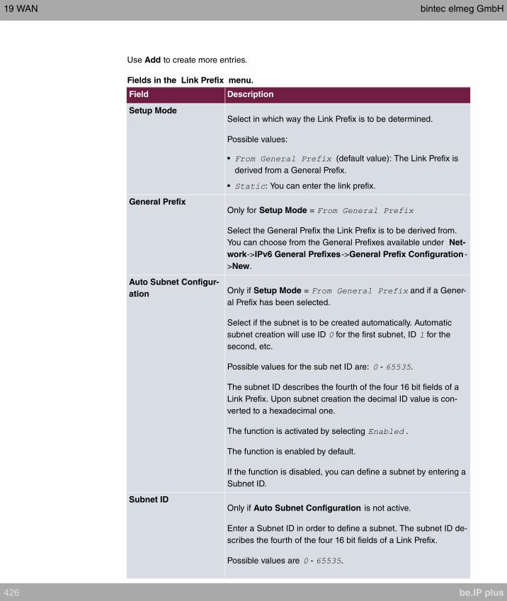
Use Add to create more entries.
Fields in the Link Prefix menu.
Field Description
Setup ModeSelect in which way the Link Prefix is to be determined.
Possible values:
• (default value): The Link Prefix is
derived from a General Prefix.
• : You can enter the link prefix.
General PrefixOnly for Setup Mode =
Select the General Prefix the Link Prefix is to be derived from.
You can choose from the General Prefixes available under Net-
work->IPv6 General Prefixes->General Prefix Configuration -
>New.
Auto Subnet Configur-
ation Only if Setup Mode = and if a Gener-
al Prefix has been selected.
Select if the subnet is to be created automatically. Automatic
subnet creation will use ID for the first subnet, ID for the
second, etc.
Possible values for the sub net ID are: - .
The subnet ID describes the fourth of the four 16 bit fields of a
Link Prefix. Upon subnet creation the decimal ID value is con-
verted to a hexadecimal one.
The function is activated by selecting .
The function is enabled by default.
If the function is disabled, you can define a subnet by entering a
Subnet ID.
Subnet IDOnly if Auto Subnet Configuration is not active.
Enter a Subnet ID in order to define a subnet. The subnet ID de-
scribes the fourth of the four 16 bit fields of a Link Prefix.
Possible values are - .
19 WAN bintec elmeg GmbH
426 be.IP plus
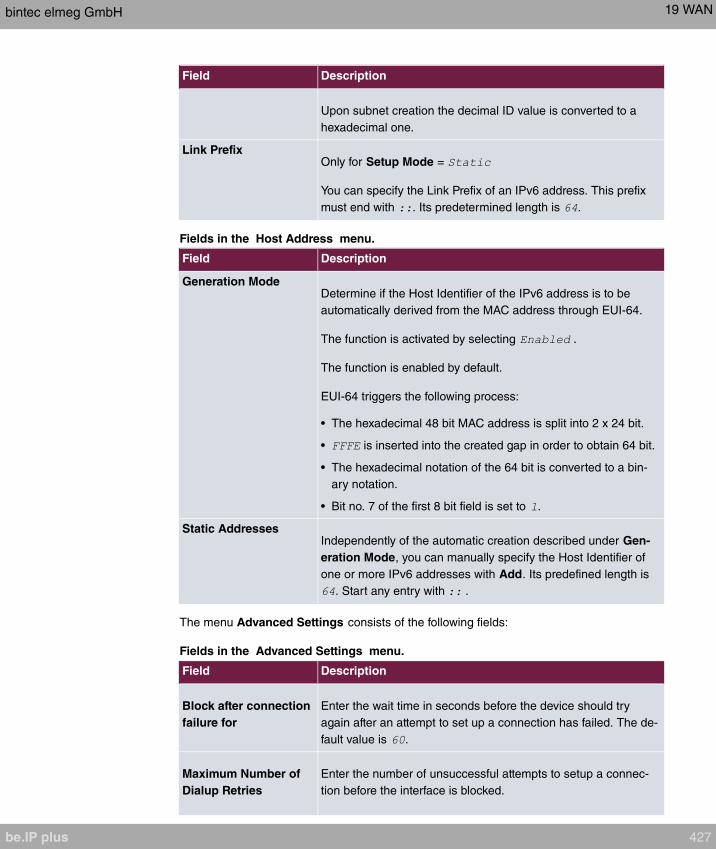
Field Description
Upon subnet creation the decimal ID value is converted to a
hexadecimal one.
Link PrefixOnly for Setup Mode =
You can specify the Link Prefix of an IPv6 address. This prefix
must end with . Its predetermined length is .
Fields in the Host Address menu.
Field Description
Generation ModeDetermine if the Host Identifier of the IPv6 address is to be
automatically derived from the MAC address through EUI-64.
The function is activated by selecting .
The function is enabled by default.
EUI-64 triggers the following process:
• The hexadecimal 48 bit MAC address is split into 2 x 24 bit.
• is inserted into the created gap in order to obtain 64 bit.
• The hexadecimal notation of the 64 bit is converted to a bin-
ary notation.
• Bit no. 7 of the first 8 bit field is set to .
Static AddressesIndependently of the automatic creation described under Gen-
eration Mode, you can manually specify the Host Identifier of
one or more IPv6 addresses with Add. Its predefined length is
. Start any entry with .
The menu Advanced Settings consists of the following fields:
Fields in the Advanced Settings menu.
Field Description
Block after connection
failure for
Enter the wait time in seconds before the device should try
again after an attempt to set up a connection has failed. The de-
fault value is .
Maximum Number of
Dialup Retries
Enter the number of unsuccessful attempts to setup a connec-
tion before the interface is blocked.
bintec elmeg GmbH 19 WAN
be.IP plus 427
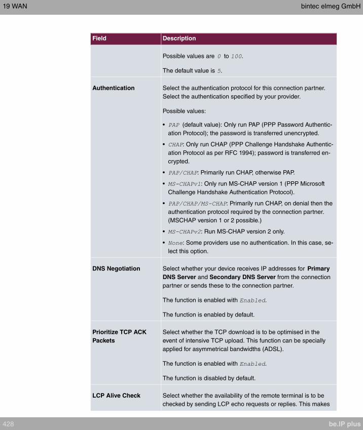
Field Description
Possible values are to .
The default value is .
Authentication Select the authentication protocol for this connection partner.
Select the authentication specified by your provider.
Possible values:
• (default value): Only run PAP (PPP Password Authentic-
ation Protocol); the password is transferred unencrypted.
• : Only run CHAP (PPP Challenge Handshake Authentic-
ation Protocol as per RFC 1994); password is transferred en-
crypted.
• : Primarily run CHAP, otherwise PAP.
• : Only run MS-CHAP version 1 (PPP Microsoft
Challenge Handshake Authentication Protocol).
• : Primarily run CHAP, on denial then the
authentication protocol required by the connection partner.
(MSCHAP version 1 or 2 possible.)
• : Run MS-CHAP version 2 only.
• : Some providers use no authentication. In this case, se-
lect this option.
DNS Negotiation Select whether your device receives IP addresses for Primary
DNS Server and Secondary DNS Server from the connection
partner or sends these to the connection partner.
The function is enabled with .
The function is enabled by default.
Prioritize TCP ACK
Packets
Select whether the TCP download is to be optimised in the
event of intensive TCP upload. This function can be specially
applied for asymmetrical bandwidths (ADSL).
The function is enabled with .
The function is disabled by default.
LCP Alive Check Select whether the availability of the remote terminal is to be
checked by sending LCP echo requests or replies. This makes
19 WAN bintec elmeg GmbH
428 be.IP plus
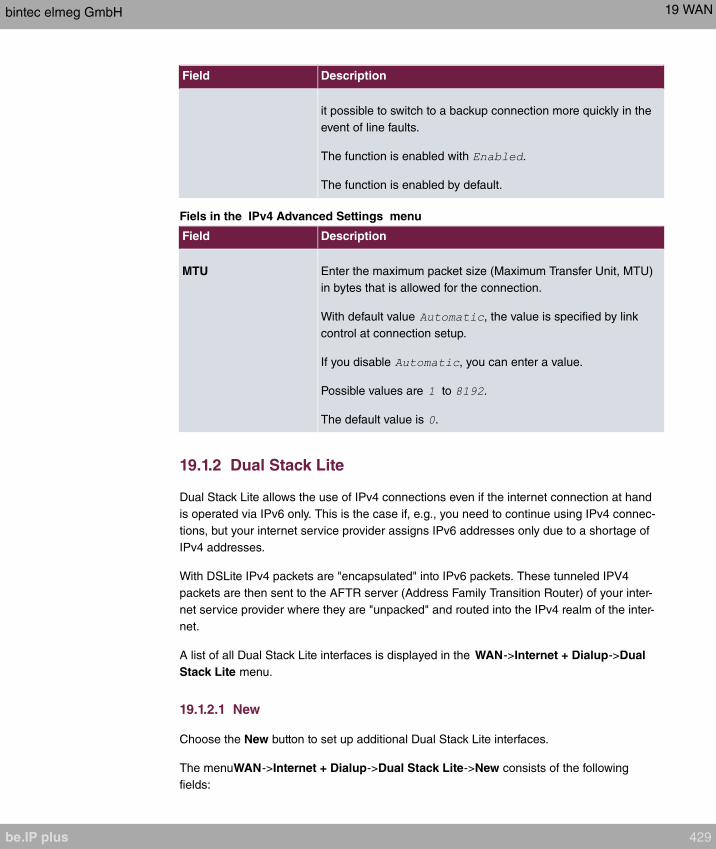
Field Description
it possible to switch to a backup connection more quickly in the
event of line faults.
The function is enabled with .
The function is enabled by default.
Fiels in the IPv4 Advanced Settings menu
Field Description
MTU Enter the maximum packet size (Maximum Transfer Unit, MTU)
in bytes that is allowed for the connection.
With default value , the value is specified by link
control at connection setup.
If you disable , you can enter a value.
Possible values are to .
The default value is .
19.1.2 Dual Stack Lite
Dual Stack Lite allows the use of IPv4 connections even if the internet connection at hand
is operated via IPv6 only. This is the case if, e.g., you need to continue using IPv4 connec-
tions, but your internet service provider assigns IPv6 addresses only due to a shortage of
IPv4 addresses.
With DSLite IPv4 packets are "encapsulated" into IPv6 packets. These tunneled IPV4
packets are then sent to the AFTR server (Address Family Transition Router) of your inter-
net service provider where they are "unpacked" and routed into the IPv4 realm of the inter-
net.
A list of all Dual Stack Lite interfaces is displayed in the WAN->Internet + Dialup->Dual
Stack Lite menu.
19.1.2.1 New
Choose the New button to set up additional Dual Stack Lite interfaces.
The menuWAN->Internet + Dialup->Dual Stack Lite->New consists of the following
fields:
bintec elmeg GmbH 19 WAN
be.IP plus 429

Fields in the Basic Parameters menu
Field Description
Description Assign a name to your Dual Stack Lite connection.
IPv6 Interface Select the IPv6 interface that is used for the DS Lite connection.
This is normally the interface of your internet connection. IPv4
packets sent via this interface are encapsulated into IPv6 pack-
ets.
AFTR Enter the IPv6 address or domain name of your Address Family
Transition Router. The provider of your IPv6 internet connection
will provide you with this information.
Default Route Select whether you want to use this connection as the default
route. This setting is useful in order to have the complete IPv4
data traffic that is to be sent over the internet be sent over the
IPv6 connection. Otherwise, you need to make the correspond-
ing adjustments to your routing.
The function is enabled with .
The function is enabled by default.
19.1.3 PPTP
A list of all PPTP interfaces is displayed in the WAN->Internet + Dialup->PPTP menu.
In this menu, you configure an Internet connection that uses the Point Tunnelling Protocol
(PPTP) to set up a connection. This is required in Austria, for example.
19.1.3.1 New
Choose the New button to set up new PPTP interfaces.
The menu WAN->Internet + Dialup->PPTP->New consists of the following fields:
Fields in the Basic Parameters menu.
Field Description
Description Enter a name for uniquely identifying the internet connection.
The first character in this field must not be a number No special
characters or umlauts must be used.
19 WAN bintec elmeg GmbH
430 be.IP plus
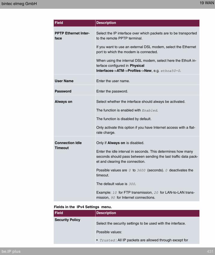
Field Description
PPTP Ethernet Inter-
face
Select the IP interface over which packets are to be transported
to the remote PPTP terminal.
If you want to use an external DSL modem, select the Ethernet
port to which the modem is connected.
When using the internal DSL modem, select here the EthoA in-
terface configured in Physical
Interfaces->ATM->Profiles->New, e.g. .
User Name Enter the user name.
Password Enter the password.
Always on Select whether the interface should always be activated.
The function is enabled with .
The function is disabled by default.
Only activate this option if you have Internet access with a flat-
rate charge.
Connection Idle
Timeout
Only if Always on is disabled.
Enter the idle interval in seconds. This determines how many
seconds should pass between sending the last traffic data pack-
et and clearing the connection.
Possible values are to (seconds). deactivates the
timeout.
The default value is .
Example: for FTP transmission, for LAN-to-LAN trans-
mission, for Internet connections.
Fields in the IPv4 Settings menu.
Field Description
Security PolicySelect the security settings to be used with the interface.
Possible values:
• : All IP packets are allowed through except for
bintec elmeg GmbH 19 WAN
be.IP plus 431

Field Description
those which are explicitly prohibited..
• (default value): Only those packets are transmit-
ted that can be attributed to a connection that has been initi-
ated from a trusted zone.
You can configure exceptions for the selected setting in the
Firewall on page 518 menu.
IP Address Mode Select whether your device is to be assigned a static IP address
or whether it should be assigned this dynamically.
Possible values:
• (default value): Your device is automatic-
ally assigned a temporarily valid IP address from the provider.
• : You enter a static IP address.
Default Route Select whether the route to this connection partner is to be
defined as the default route.
The function is enabled with .
The function is enabled by default.
Create NAT Policy Specify whether Network Address Translation (NAT) is to be ac-
tivated.
The function is enabled with .
The function is enabled by default.
Local IP Address Only for IP Address Mode =
Assign an IP address from your LAN to the PPT interface, which
is to be used as your device's internal source address.
Route Entries Only if IP Address Mode =
Define other routing entries for this PPTP partner.
Add new entries with Add.
• : IP address of the destination host or
network.
• : Netmask for Remote IP Address If no entry is
19 WAN bintec elmeg GmbH
432 be.IP plus
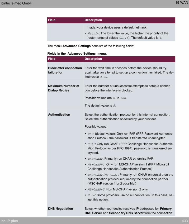
Field Description
made, your device uses a default netmask.
• : The lower the value, the higher the priority of the
route (range of values ... ). The default value is .
The menu Advanced Settings consists of the following fields:
Fields in the Advanced Settings menu.
Field Description
Block after connection
failure for
Enter the wait time in seconds before the device should try
again after an attempt to set up a connection has failed. The de-
fault value is .
Maximum Number of
Dialup Retries
Enter the number of unsuccessful attempts to setup a connec-
tion before the interface is blocked.
Possible values are to .
The default value is .
Authentication Select the authentication protocol for this Internet connection.
Select the authentication specified by your provider.
Possible values:
• (default value): Only run PAP (PPP Password Authentic-
ation Protocol); the password is transferred unencrypted.
• : Only run CHAP (PPP Challenge Handshake Authentic-
ation Protocol as per RFC 1994); password is transferred en-
crypted.
• : Primarily run CHAP, otherwise PAP.
• : Only run MS-CHAP version 1 (PPP Microsoft
Challenge Handshake Authentication Protocol).
• : Primarily run CHAP, on denial then the
authentication protocol required by the connection partner.
(MSCHAP version 1 or 2 possible.)
• : Run MS-CHAP version 2 only.
• : Some providers use no authentication. In this case, se-
lect this option.
DNS Negotiation Select whether your device receives IP addresses for Primary
DNS Server and Secondary DNS Server from the connection
bintec elmeg GmbH 19 WAN
be.IP plus 433
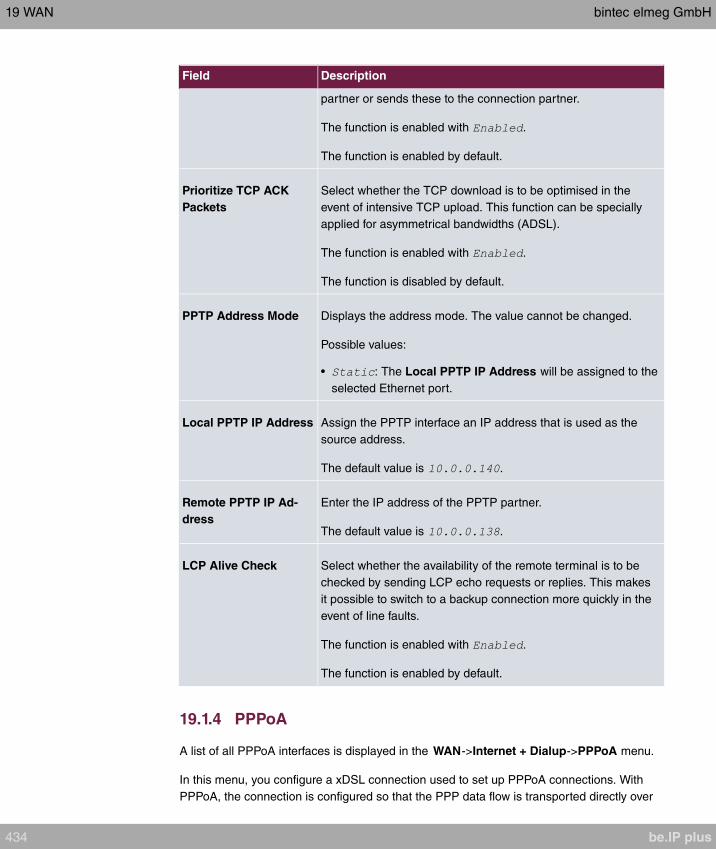
Field Description
partner or sends these to the connection partner.
The function is enabled with .
The function is enabled by default.
Prioritize TCP ACK
Packets
Select whether the TCP download is to be optimised in the
event of intensive TCP upload. This function can be specially
applied for asymmetrical bandwidths (ADSL).
The function is enabled with .
The function is disabled by default.
PPTP Address Mode Displays the address mode. The value cannot be changed.
Possible values:
• : The Local PPTP IP Address will be assigned to the
selected Ethernet port.
Local PPTP IP Address Assign the PPTP interface an IP address that is used as the
source address.
The default value is .
Remote PPTP IP Ad-
dress
Enter the IP address of the PPTP partner.
The default value is .
LCP Alive Check Select whether the availability of the remote terminal is to be
checked by sending LCP echo requests or replies. This makes
it possible to switch to a backup connection more quickly in the
event of line faults.
The function is enabled with .
The function is enabled by default.
19.1.4 PPPoA
A list of all PPPoA interfaces is displayed in the WAN->Internet + Dialup->PPPoA menu.
In this menu, you configure a xDSL connection used to set up PPPoA connections. With
PPPoA, the connection is configured so that the PPP data flow is transported directly over
19 WAN bintec elmeg GmbH
434 be.IP plus

an ATM network (RFC 2364). This is required by some providers. Note your provider's spe-
cifications.
When using the internal DSL modem, a PPPoA interface must be configured with Client
Type = for this connection in WAN->ATM->Profiles->New.
19.1.4.1 New
Choose the New button to set up new PPPoA interfaces.
The menu WAN->Internet + Dialup->PPPoA->New consists of the following fields:
Fields in the Basic Parameters menu.
Field Description
Description Enter a name for uniquely identifying the connection partner.
The first character in this field must not be a number No special
characters or umlauts must be used.
ATM PVC Select an ATM profile created in the ATM->Profiles menu, in-
dicated by the global identifiers VPI and VCI specified by the
provider.
User Name Enter the user name.
Password Enter the password for the PPPoA connection.
Always on Select whether the interface should always be activated.
The function is enabled with .
The function is disabled by default.
Only activate this option if you have Internet access with a flat-
rate charge.
Connection Idle
Timeout
Only if Always on is disabled.
Enter the idle time in seconds for static short hold. The static
short hold setting determines how many seconds should pass
between sending the last traffic data packet and clearing the
connection.
Possible values are to (seconds). deactivates the
short hold.
bintec elmeg GmbH 19 WAN
be.IP plus 435
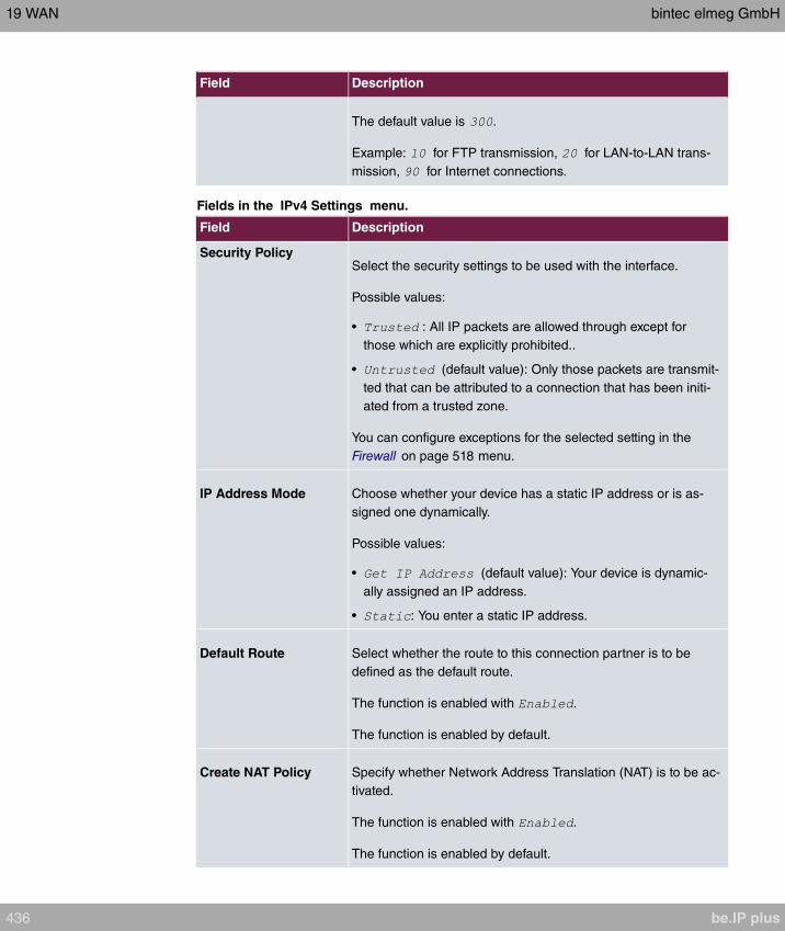
Field Description
The default value is .
Example: for FTP transmission, for LAN-to-LAN trans-
mission, for Internet connections.
Fields in the IPv4 Settings menu.
Field Description
Security PolicySelect the security settings to be used with the interface.
Possible values:
• : All IP packets are allowed through except for
those which are explicitly prohibited..
• (default value): Only those packets are transmit-
ted that can be attributed to a connection that has been initi-
ated from a trusted zone.
You can configure exceptions for the selected setting in the
Firewall on page 518 menu.
IP Address Mode Choose whether your device has a static IP address or is as-
signed one dynamically.
Possible values:
• (default value): Your device is dynamic-
ally assigned an IP address.
• : You enter a static IP address.
Default Route Select whether the route to this connection partner is to be
defined as the default route.
The function is enabled with .
The function is enabled by default.
Create NAT Policy Specify whether Network Address Translation (NAT) is to be ac-
tivated.
The function is enabled with .
The function is enabled by default.
19 WAN bintec elmeg GmbH
436 be.IP plus

Field Description
Local IP Address Only for IP Address Mode =
Enter the static IP address you received from your provider.
Route Entries Only if IP Address Mode =
Define other routing entries for this connection partner.
Add new entries with Add.
• : IP address of the destination host or
network.
• : Netmask for Remote IP Address If no entry is
made, your device uses a default netmask.
• : The lower the value, the higher the priority of the
route (range of values ... ). The default value is .
Fields in the IPv6 Settings menu
Field Description
IPv6 Select whether the selected ATM profile should use Internet
Protocol version 6 (IPv6) for data transmission.
The function is activated by selecting .
The function is disabled by default.
Security Policy Select the security settings to be used with the ATM profile.
Possible values:
• (default value): Only those packets are transmit-
ted that can be attributed to a connection that has been initi-
ated from a trusted zone.
We recommend you use this setting if you want to use IPv6
outside of your LAN.
• : All IP packets are allowed through except for those
which are explicitly prohibited.
We recommend you use this setting if you want to use IPv6
on your LAN.
You can configure exceptions for the selected setting in the
bintec elmeg GmbH 19 WAN
be.IP plus 437
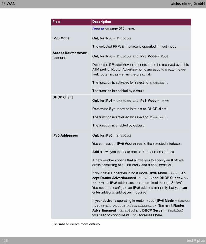
Field Description
Firewall on page 518 menu.
IPv6 Mode Only for IPv6 =
The selected PPPoE interface is operated in host mode.
Accept Router Advert-
isement Only for IPv6 = and IPv6 Mode =
Determine if Router Advertisements are to be received over this
ATM profile. Router Advertisements are used to create the de-
fault router list as well as the prefix list.
The function is activated by selecting .
The function is enabled by default.
DHCP ClientOnly for IPv6 = and IPv6 Mode =
Determine if your device is to act as DHCP client.
The function is activated by selecting .
The function is enabled by default.
IPv6 Addresses Only for IPv6 =
You can assign IPv6 Addresses to the selected interface..
Add allows you to create one or more address entries.
A new windows opens that allows you to specify an IPv6 ad-
dress consisting of a Link Prefix and a host identifier.
If your device operates in host mode (IPv6 Mode = , Ac-
cept Router Advertisement and DHCP Client =
), its IPv6 addresses are determined through SLAAC.
You need not configure an IPv6 address manually, but you can
enter addtional addresses if desired.
If your device is operating in router mode ( IPv6 Mode =
, Transmit Router
Advertisement = and DHCP Server = ),
you need to configure its IPv6 addresses here.
Use Add to create more entries.
19 WAN bintec elmeg GmbH
438 be.IP plus
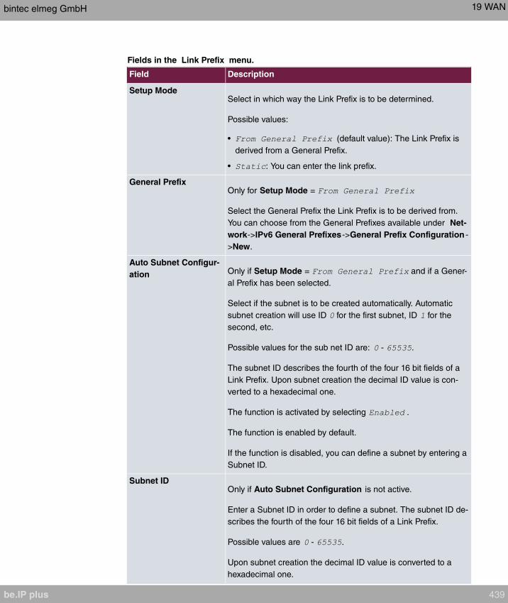
Fields in the Link Prefix menu.
Field Description
Setup ModeSelect in which way the Link Prefix is to be determined.
Possible values:
• (default value): The Link Prefix is
derived from a General Prefix.
• : You can enter the link prefix.
General PrefixOnly for Setup Mode =
Select the General Prefix the Link Prefix is to be derived from.
You can choose from the General Prefixes available under Net-
work->IPv6 General Prefixes->General Prefix Configuration -
>New.
Auto Subnet Configur-
ation Only if Setup Mode = and if a Gener-
al Prefix has been selected.
Select if the subnet is to be created automatically. Automatic
subnet creation will use ID for the first subnet, ID for the
second, etc.
Possible values for the sub net ID are: - .
The subnet ID describes the fourth of the four 16 bit fields of a
Link Prefix. Upon subnet creation the decimal ID value is con-
verted to a hexadecimal one.
The function is activated by selecting .
The function is enabled by default.
If the function is disabled, you can define a subnet by entering a
Subnet ID.
Subnet IDOnly if Auto Subnet Configuration is not active.
Enter a Subnet ID in order to define a subnet. The subnet ID de-
scribes the fourth of the four 16 bit fields of a Link Prefix.
Possible values are - .
Upon subnet creation the decimal ID value is converted to a
hexadecimal one.
bintec elmeg GmbH 19 WAN
be.IP plus 439

Field Description
Link PrefixOnly for Setup Mode =
You can specify the Link Prefix of an IPv6 address. This prefix
must end with . Its predetermined length is .
Fields in the Host Address menu.
Field Description
Generation ModeDetermine if the Host Identifier of the IPv6 address is to be
automatically derived from the MAC address through EUI-64.
The function is activated by selecting .
The function is enabled by default.
EUI-64 triggers the following process:
• The hexadecimal 48 bit MAC address is split into 2 x 24 bit.
• is inserted into the created gap in order to obtain 64 bit.
• The hexadecimal notation of the 64 bit is converted to a bin-
ary notation.
• Bit no. 7 of the first 8 bit field is set to .
Static AddressesIndependently of the automatic creation described under Gen-
eration Mode, you can manually specify the Host Identifier of
one or more IPv6 addresses with Add. Its predefined length is
. Start any entry with .
The menu Advanced Settings consists of the following fields:
Fields in the Advanced Settings menu.
Field Description
Block after connection
failure for
Enter the wait time in seconds before the device should try
again after an attempt to set up a connection has failed. The de-
fault value is .
Maximum Number of
Dialup Retries
Enter the number of unsuccessful attempts to setup a connec-
tion before the interface is blocked.
Possible values are to .
The default value is .
19 WAN bintec elmeg GmbH
440 be.IP plus

Field Description
Authentication Select the authentication protocol for this Internet connection.
Select the authentication specified by your provider.
Possible values:
• (default value): Only run PAP (PPP Password Authentic-
ation Protocol); the password is transferred unencrypted.
• : Only run CHAP (PPP Challenge Handshake Authentic-
ation Protocol as per RFC 1994); password is transferred en-
crypted.
• : Primarily run CHAP, otherwise PAP.
• : Only run MS-CHAP version 1 (PPP Microsoft
Challenge Handshake Authentication Protocol).
• : Primarily run CHAP, on denial then the
authentication protocol required by the connection partner.
(MSCHAP version 1 or 2 possible.)
• : Run MS-CHAP version 2 only.
• : Some providers use no authentication. In this case, se-
lect this option.
DNS Negotiation Select whether your device receives IP addresses for Primary
DNS Server and Secondary DNS Server from the connection
partner or sends these to the connection partner.
The function is enabled with .
The function is enabled by default.
Prioritize TCP ACK
Packets
Select whether the TCP download is to be optimised in the
event of intensive TCP upload. This function can be specially
applied for asymmetrical bandwidths (ADSL).
The function is enabled with .
The function is disabled by default.
LCP Alive Check Select whether the availability of the remote terminal is to be
checked by sending LCP echo requests or replies. This is re-
commended for leased lines, PPTP and L2TP connections.
The function is enabled with .
The function is enabled by default.
bintec elmeg GmbH 19 WAN
be.IP plus 441

19.1.5 ISDN
A list of all ISDN interfaces in TE mode (ISDN extern)is displayed in the WAN->Internet +
Dialup->ISDN menu.
In this menu, you configure the following ISDN connections:
• Internet access over ISDN
• LAN to LAN connection over ISDN
• Remote (Mobile) dial-in
• Use of the ISDN Callback function
19.1.5.1 New
Choose the New button to set up new ISDN interfaces.
The menu WAN->Internet + Dialup->ISDN->New consists of the following fields:
Fields in the Basic Parameters menu.
Field Description
Description Enter a name for uniquely identifying the connection partner.
The first character in this field must not be a number No special
characters or umlauts must be used.
Connection Type Select which layer 1 protocol your device should use.
This setting applies for outgoing connections to the connection
partner and only for incoming connections from the connection
partner if they could be identified on the basis of the calling
party number.
Possible values:
• : For 64-kbps ISDN data connections.
• : For 56-kbps ISDN data connections.
User Name Enter your device code (local PPP user name).
Remote User (for Dial-
in only)
Enter the code of the remote terminal (remote PPP user name).
Password Enter the password.
19 WAN bintec elmeg GmbH
442 be.IP plus

Field Description
Always on Select whether the interface should always be activated.
The function is enabled with .
The function is disabled by default.
Only activate this option if you have Internet access with a flat-
rate charge.
Connection Idle
Timeout
Only if Always on is disabled.
Enter the idle interval in seconds. This determines how many
seconds should pass between sending the last traffic data pack-
et and clearing the connection.
Possible values are to (seconds). deactivates the
timeout. The default value is .
Fields in the IP Mode and Routes menu.
Field Description
IP Address Mode Select whether your device is to be assigned a static IP address
or whether it should be assigned this dynamically.
Possible values:
• (default value): You enter a static IP address.
• : Your device dynamically assigns an
IP address to the remote terminal.
• : Your device is dynamically assigned an
IP address.
Default Route Only for IP Address Mode = and
Select whether the route to this connection partner is to be
defined as the default route.
The function is enabled with .
The function is disabled by default.
Create NAT Policy Only for IP Address Mode = and
When you configure an ISDN Internet connection, specify
whether Network Address Translation (NAT) is to be activated.
bintec elmeg GmbH 19 WAN
be.IP plus 443
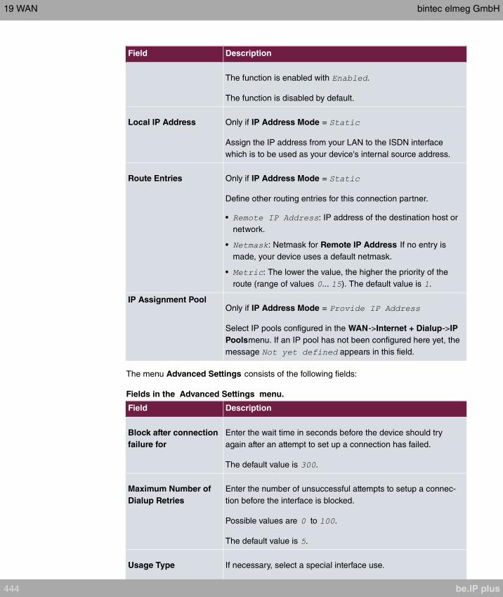
Field Description
The function is enabled with .
The function is disabled by default.
Local IP Address Only if IP Address Mode =
Assign the IP address from your LAN to the ISDN interface
which is to be used as your device's internal source address.
Route Entries Only if IP Address Mode =
Define other routing entries for this connection partner.
• : IP address of the destination host or
network.
• : Netmask for Remote IP Address If no entry is
made, your device uses a default netmask.
• : The lower the value, the higher the priority of the
route (range of values ... ). The default value is .
IP Assignment PoolOnly if IP Address Mode =
Select IP pools configured in the WAN->Internet + Dialup->IP
Poolsmenu. If an IP pool has not been configured here yet, the
message appears in this field.
The menu Advanced Settings consists of the following fields:
Fields in the Advanced Settings menu.
Field Description
Block after connection
failure for
Enter the wait time in seconds before the device should try
again after an attempt to set up a connection has failed.
The default value is .
Maximum Number of
Dialup Retries
Enter the number of unsuccessful attempts to setup a connec-
tion before the interface is blocked.
Possible values are to .
The default value is .
Usage Type If necessary, select a special interface use.
19 WAN bintec elmeg GmbH
444 be.IP plus

Field Description
Possible values:
• (default value): No special type is selected.
• : The interface is used for incoming dialup con-
nections and callbacks initiated externally.
• : The interface is defined as
multi-user connection partner, i.e. several clients dial in with
the same user name and password.
Authentication Select the authentication protocol for this PPTP partner.
Possible values:
• (default value): Only run PAP (PPP Password Authentic-
ation Protocol); the password is transferred unencrypted.
• : Only run CHAP (PPP Challenge Handshake Authentic-
ation Protocol as per RFC 1994); password is transferred en-
crypted.
• : Primarily run CHAP, otherwise PAP.
• : Only run MS-CHAP version 1 (PPP Microsoft
Challenge Handshake Authentication Protocol).
• : Primarily run CHAP, on denial then the
authentication protocol required by the connection partner.
(MSCHAP version 1 or 2 possible.)
• : Run MS-CHAP version 2 only.
• : Some providers use no authentication. In this case, se-
lect this option.
Encryption Only for Authentication =
If necessary, select the type of encryption that should be used
for data traffic to the connection partner. This is only possible if
STAC or MS-STAC compression is not activated for the con-
nection. If Encryption is set, the remote terminal must also sup-
port it, otherwise a connection cannot be set up.
Possible values:
• (default value): MPP encryption is not used.
• : MPP encryption V2 with 128 bit is used to RFC
3078.
bintec elmeg GmbH 19 WAN
be.IP plus 445

Field Description
• : MPP encryption V2 with 128 bit is
used as compatible with Microsoft and Cisco.
Callback Mode Select the Callback Mode function.
Possible values:
• (default value): Your device does not call back.
• : Select one of the following options:
• : Your device calls the connection
partner to request a callback.
• : Your device calls the connection
partner to request a callback via CBCP (Callback Control
Protocol). Needed for Windows clients.
• : Select one of the following options:
• : Your device calls back im-
mediately when requested to do so by the connection part-
ner.
• : Your device calls back after a
period of time suggested by the Microsoft client (NT: 10
seconds, new systems: 12 seconds. It uses the call number
(Entries->Call Number) with the Mode or
entered for the connection partner. If no number is
entered, the required number can be reported by the caller
in a PPP negotiation. This setting should be avoided where
possible for security reasons. At present, this cannot be
avoided when connecting mobile Microsoft clients via a
DCN.
• : Your device calls back after ap-
prox. four seconds if your device is requested to do so by
the connection partner. Only makes sense for CLID.
• : like
with the option of termination.
This setting should be avoided for security reasons. The Mi-
crosoft client also has the option of aborting callback and
maintaining the initial connection to your device without call-
back. This only applies if no fixed, outgoing number has
been configured for the connection partner. This is done by
closing the dialog box that appears with Cancel.
Fields in the Bandwith on Demand Options menu.
19 WAN bintec elmeg GmbH
446 be.IP plus
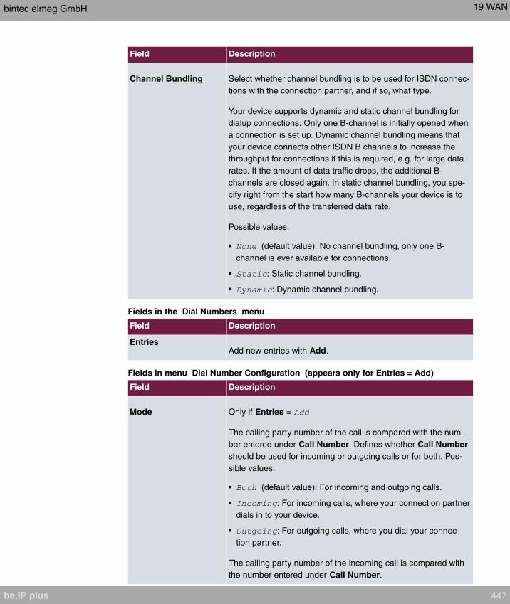
Field Description
Channel Bundling Select whether channel bundling is to be used for ISDN connec-
tions with the connection partner, and if so, what type.
Your device supports dynamic and static channel bundling for
dialup connections. Only one B-channel is initially opened when
a connection is set up. Dynamic channel bundling means that
your device connects other ISDN B channels to increase the
throughput for connections if this is required, e.g. for large data
rates. If the amount of data traffic drops, the additional B-
channels are closed again. In static channel bundling, you spe-
cify right from the start how many B-channels your device is to
use, regardless of the transferred data rate.
Possible values:
• (default value): No channel bundling, only one B-
channel is ever available for connections.
• : Static channel bundling.
• : Dynamic channel bundling.
Fields in the Dial Numbers menu
Field Description
EntriesAdd new entries with Add.
Fields in menu Dial Number Configuration (appears only for Entries = Add)
Field Description
Mode Only if Entries =
The calling party number of the call is compared with the num-
ber entered under Call Number. Defines whether Call Number
should be used for incoming or outgoing calls or for both. Pos-
sible values:
• (default value): For incoming and outgoing calls.
• : For incoming calls, where your connection partner
dials in to your device.
• : For outgoing calls, where you dial your connec-
tion partner.
The calling party number of the incoming call is compared with
the number entered under Call Number.
bintec elmeg GmbH 19 WAN
be.IP plus 447
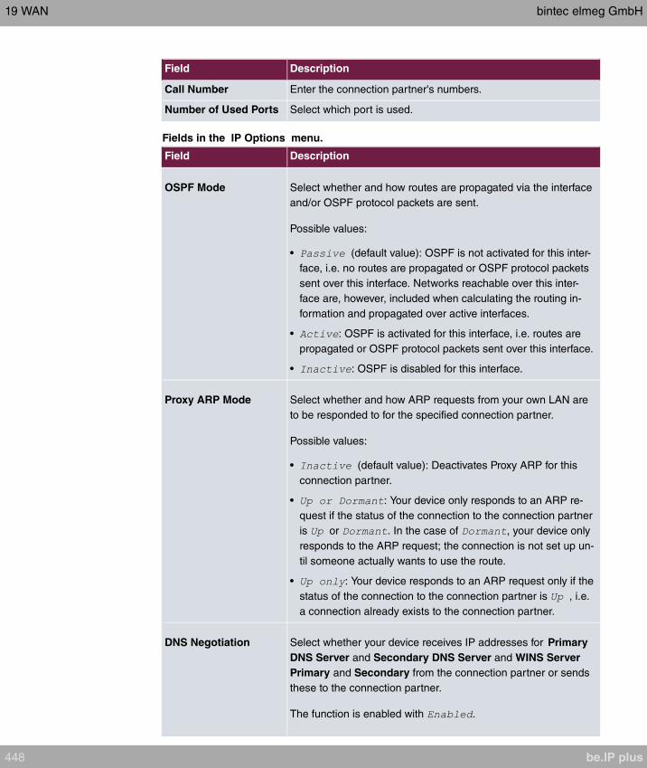
Field Description
Call Number Enter the connection partner's numbers.
Number of Used Ports Select which port is used.
Fields in the IP Options menu.
Field Description
OSPF Mode Select whether and how routes are propagated via the interface
and/or OSPF protocol packets are sent.
Possible values:
• (default value): OSPF is not activated for this inter-
face, i.e. no routes are propagated or OSPF protocol packets
sent over this interface. Networks reachable over this inter-
face are, however, included when calculating the routing in-
formation and propagated over active interfaces.
• : OSPF is activated for this interface, i.e. routes are
propagated or OSPF protocol packets sent over this interface.
• : OSPF is disabled for this interface.
Proxy ARP Mode Select whether and how ARP requests from your own LAN are
to be responded to for the specified connection partner.
Possible values:
• (default value): Deactivates Proxy ARP for this
connection partner.
• : Your device only responds to an ARP re-
quest if the status of the connection to the connection partner
is or . In the case of , your device only
responds to the ARP request; the connection is not set up un-
til someone actually wants to use the route.
• : Your device responds to an ARP request only if the
status of the connection to the connection partner is , i.e.
a connection already exists to the connection partner.
DNS Negotiation Select whether your device receives IP addresses for Primary
DNS Server and Secondary DNS Server and WINS Server
Primary and Secondary from the connection partner or sends
these to the connection partner.
The function is enabled with .
19 WAN bintec elmeg GmbH
448 be.IP plus
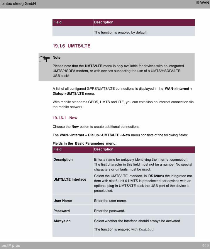
Field Description
The function is enabled by default.
19.1.6 UMTS/LTE
Note
Please note that the UMTS/LTE menu is only available for devices with an integrated
UMTS/HSDPA modem, or with devices supporting the use of a UMTS/HSDPA/LTE
USB stick!
A list of all configured GPRS/UMTS/LTE connections is displayed in the WAN->Internet +
Dialup->UMTS/LTE menu.
With mobile standards GPRS, UMTS and LTE, you can establish an internet connection via
the mobile network.
19.1.6.1 New
Choose the New button to create additional connections.
The WAN->Internet + Dialup->UMTS/LTE->New menu consists of the following fields:
Fields in the Basic Parameters menu.
Field Description
Description Enter a name for uniquely identifying the internet connection.
The first character in this field must not be a number No special
characters or umlauts must be used.
UMTS/LTE InterfaceSelect the UMTS/LTE interface. In RS120wu the integrated mo-
dem with slot 6 unit 0 UMTS is preselected; for devices with an
optional plug-in UMTS/LTE stick the USB port of the device is
preselected.
User Name Enter the user name.
Password Enter the password.
Always on Select whether the interface should always be activated.
The function is enabled with .
bintec elmeg GmbH 19 WAN
be.IP plus 449
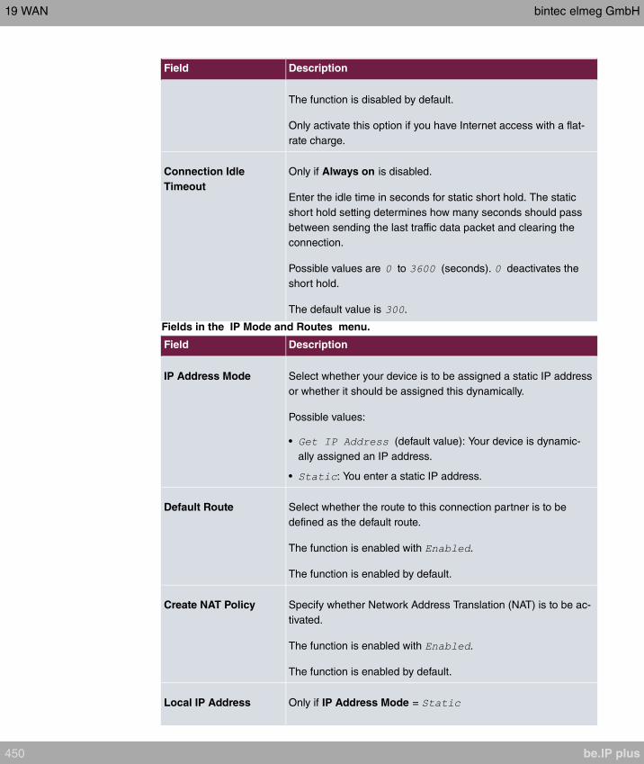
Field Description
The function is disabled by default.
Only activate this option if you have Internet access with a flat-
rate charge.
Connection Idle
Timeout
Only if Always on is disabled.
Enter the idle time in seconds for static short hold. The static
short hold setting determines how many seconds should pass
between sending the last traffic data packet and clearing the
connection.
Possible values are to (seconds). deactivates the
short hold.
The default value is .
Fields in the IP Mode and Routes menu.
Field Description
IP Address Mode Select whether your device is to be assigned a static IP address
or whether it should be assigned this dynamically.
Possible values:
• (default value): Your device is dynamic-
ally assigned an IP address.
• : You enter a static IP address.
Default Route Select whether the route to this connection partner is to be
defined as the default route.
The function is enabled with .
The function is enabled by default.
Create NAT Policy Specify whether Network Address Translation (NAT) is to be ac-
tivated.
The function is enabled with .
The function is enabled by default.
Local IP Address Only if IP Address Mode =
19 WAN bintec elmeg GmbH
450 be.IP plus
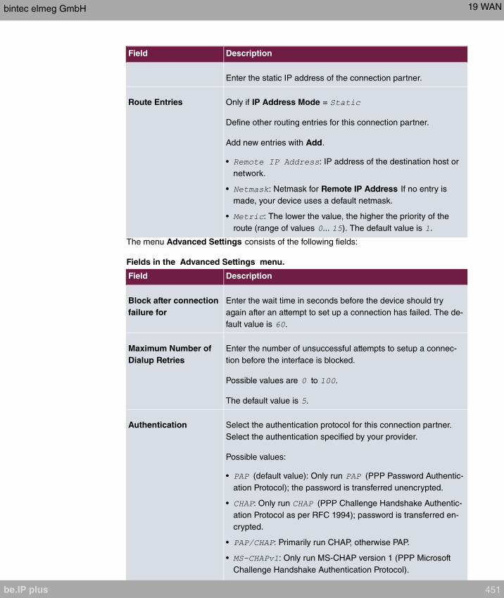
Field Description
Enter the static IP address of the connection partner.
Route Entries Only if IP Address Mode =
Define other routing entries for this connection partner.
Add new entries with Add.
• : IP address of the destination host or
network.
• : Netmask for Remote IP Address If no entry is
made, your device uses a default netmask.
• : The lower the value, the higher the priority of the
route (range of values ... ). The default value is .
The menu Advanced Settings consists of the following fields:
Fields in the Advanced Settings menu.
Field Description
Block after connection
failure for
Enter the wait time in seconds before the device should try
again after an attempt to set up a connection has failed. The de-
fault value is .
Maximum Number of
Dialup Retries
Enter the number of unsuccessful attempts to setup a connec-
tion before the interface is blocked.
Possible values are to .
The default value is .
Authentication Select the authentication protocol for this connection partner.
Select the authentication specified by your provider.
Possible values:
• (default value): Only run (PPP Password Authentic-
ation Protocol); the password is transferred unencrypted.
• : Only run (PPP Challenge Handshake Authentic-
ation Protocol as per RFC 1994); password is transferred en-
crypted.
• : Primarily run CHAP, otherwise PAP.
• : Only run MS-CHAP version 1 (PPP Microsoft
Challenge Handshake Authentication Protocol).
bintec elmeg GmbH 19 WAN
be.IP plus 451

Field Description
• : Primarily run CHAP, on denial then the
authentication protocol required by the connection partner.
(MSCHAP version 1 or 2 possible.)
• : Run MS-CHAP version 2 only.
• : Some providers use no authentication. In this case, se-
lect this option.
DNS Negotiation Select whether your device receives IP addresses for DNS
Serverprimary domain name server Primary and DNS
Serversecondary domain name server Secondary from the
connection partner or sends these to the connection partner.
The function is enabled with .
The function is enabled by default.
Prioritize TCP ACK
Packets
Select whether the TCP download is to be optimised in the
event of intensive TCP upload. This function can be specially
applied for asymmetrical bandwidths (ADSL).
The function is enabled with .
The function is disabled by default.
LCP Alive Check Select whether the availability of the remote terminal is to be
checked by sending LCP echo requests or replies. This makes
it possible to switch to a backup connection more quickly in the
event of line faults.
The function is enabled with .
The function is enabled by default.
19.1.7 IP Pools
Note
Note that the menu IP Pools is only available if a port in the menu Physical Inter-
faces->ISDN Ports-> ISDN Configuration is set to external operation (TE mode). A
corresponding adapter which is available seperately needs to be connected for extern-
al operation.
19 WAN bintec elmeg GmbH
452 be.IP plus

The IP Pools menu displays a list of all IP pools.
Your device can operate as a dynamic IP address server for PPP connections. You can
use this function by providing one or more pools of IP addresses. These IP addresses can
be assigned to dialling-in connection partners for the duration of the connection.
Any host routes entered always have priority over IP addresses from the address pools.
This means that, if an incoming call has been authenticated, your device first checks
whether a host route is entered in the routing table for this caller. If not, your device can al-
locate an IP address from an address pool (if available). If address pools have more than
one IP address, you cannot specify which connection partner receives which address. The
addresses are initially assigned in order. If a new dial-in takes place within an interval of
one hour, an attempt is made to allocate the same IP address that was assigned to this
partner the previous time.
19.1.7.1 Edit or New
Choose the New button to set up new IP address pools. Choose the icon to edit exist-
ing entries.
Fields in the menu Basic Parameters
Field Description
IP Pool Name Enter any description to uniquely identify the IP pool.
IP Address Range Enter the first (first field) and last (second field) IP address of
the IP address pool.
DNS Server Primary: Enter the IP address of the DNS server that is to be
used, preferably, by clients who draw an address from this pool.
Secondary: Optionally, enter the IP address of an alternative
DNS server.
19.2 ATM
ATM (Asynchronous Transfer Mode) is a data transmission procedure that was originally
designed for broadband ISDN.
ATM is currently used in high-speed networks. You will need ATM, for example, if you want
high-speed access to the Internet via the integrated ADSL or SHDSL modem.
In an ATM network, different applications such as speech, video and data, can be transmit-
ted side-by-side in the asynchronous time multiplex procedure. Each transmitter is provided
bintec elmeg GmbH 19 WAN
be.IP plus 453

with time sections for transmitting data. With asynchronous transmission, unused time sec-
tions of a transmitter are used by another transmitter.
With ATM, the packet switching procedure is connected-based. A virtual connection is used
for data transmission that negotiates between the transmitter and recipient or is configured
on both sides. This determines the route that the data should take, for example. Multiple
virtual connections can be set up over a single physical interface.
The data is transmitted in so-called cells or slots of constant size. Each cell consists of 48
bytes of usage data and 5 bytes of control information. The control information contains,
amongst other things, the ATM address which is similar to the Internet address. The ATM
address is made up of the Virtual Path Identifier (VPI) and the Virtual Connection Identifier
(VCI); this identifies the virtual connection.
Various types of traffic flows are transported over ATM. To take account of the various de-
mands of these traffic flows on the networks, e.g. in terms of cell loss and delay time, suit-
able values can be defined using the service categories. Uncompressed video data, for ex-
ample, requires different parameters to time-uncritical data.
In ATM networks Quality of Service (QoS) is available, i.e. the size of various network para-
meters, such as bit rate, delay and jitter can be guaranteed.
OAM (Operation, Administration and Maintenance) is used to monitor the data transmission
in ATM. OAM includes configuration management, error management and performance
measurement.
19.2.1 Profiles
A list of all ATM profiles is displayed in the WAN->ATM->Profiles menu.
If the connection for your Internet access is set up using the internal modem, the ATM con-
nection parameters must be set for this. An ATM profile combines a set of parameters for a
specific provider.
Note
The ATM encapsulations are described in RFCs 1483 and 2684. You will find the
RFCs on the relevant pages of the IETF (www.ietf.org/rfc.html ).
19.2.1.1 New
Choose the New button to set up new ATM profiles.
The menu WAN->ATM->Profiles->New consists of the following fields:
19 WAN bintec elmeg GmbH
454 be.IP plus

Fields in the ATM Profiles Parameter menu.
Field Description
Provider Select one of the preconfigured ATM profiles for your provider
from the list or manually define the profile using
.
Description Only for Provider =
Enter the desired description for the connection.
ATM Interface Only if several ATM interfaces are available, e.g. if several inter-
faces are separately configured in devices with SHDSL.
Select the ATM interface that you wish to use for the connec-
tion.
Type Only for Provider =
Select the protocol for the ATM connection.
Possible values:
• (default value): Ethernet over ATM
(EthoA) is used for the ATM connection (Permanent Virtual
Circuit, PVC).
• : Routed Protocols over
ATM (RPoA) is used for the ATM connection (Permanent Vir-
tual Circuit, PVC).
• : PPP over ATM (PPPoA) is used for the ATM
connection (Permanent Virtual Circuit, PVC).
Virtual Path Identifier
(VPI)
Only for Provider =
Enter the VPI value of the ATM connection. The VPI is the iden-
tification number of the virtual path to be used. Note your pro-
vider's instructions.
Possible values are to .
The default value is .
Virtual Channel Identi-
fier (VCI)
Only for Provider =
Enter the VCI value of the ATM connection. The VCI is the iden-
bintec elmeg GmbH 19 WAN
be.IP plus 455

Field Description
tification number of the virtual channel. A virtual channel is the
logical connection for the transport of ATM cells between two or
more points. Note your provider's instructions.
Possible values are to .
The default value is 32.
Encapsulation Only for Provider =
Select the encapsulation to be used. Note your provider's in-
structions.
Possible values (in accordance with RFC 2684):
• (Default value for Ethernet over
ATM : Is only displayed for Type = .
Bridged Ethernet with LLC/SNAP encapsulation without
Frame Check Sequence (checksums).
• : only displayed for Type =
.
Bridged Ethernet with LLC/SNAP encapsulation with Frame
Check Sequence (checksums).
• (default value for Routed Protocols over ATM): Is
only displayed for Type = .
Encapsulation with LLC/SNAP header, suitable for IP routing.
• : only displayed for Type = .
Encapsulation with LLC header.
• (default value for PPP over ATM):
Bridged Ethernet without additional encapsulation (Null En-
capsulation) with Frame Check Sequence (checksums).
Fields in menu Ethernet over ATM Settings (appears only for Type = Ethernet over
ATM)
Field Description
Default Ethernet for
PPPoE Interfaces
Only for Type =
Select whether this Ethernet-over-ATM interface is to be used
for all PPPoE connections
19 WAN bintec elmeg GmbH
456 be.IP plus
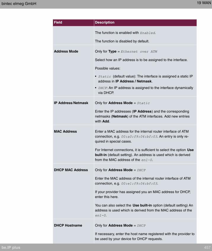
Field Description
The function is enabled with .
The function is disabled by default.
Address Mode Only for Type =
Select how an IP address is to be assigned to the interface.
Possible values:
• (default value): The interface is assigned a static IP
address in IP Address / Netmask.
• : An IP address is assigned to the interface dynamically
via DHCP.
IP Address/Netmask Only for Address Mode =
Enter the IP addresses (IP Address) and the corresponding
netmasks (Netmask) of the ATM interfaces. Add new entries
with Add.
MAC Address Enter a MAC address for the internal router interface of ATM
connection, e.g. . An entry is only re-
quired in special cases.
For Internet connections, it is sufficient to select the option Use
built-in (default setting). An address is used which is derived
from the MAC address of the .
DHCP MAC Address Only for Address Mode =
Enter the MAC address of the internal router interface of ATM
connection, e.g. .
If your provider has assigned you an MAC address for DHCP,
enter this here.
You can also select the Use built-in option (default setting) An
address is used which is derived from the MAC address of the
.
DHCP Hostname Only for Address Mode =
If necessary, enter the host name registered with the provider to
be used by your device for DHCP requests.
bintec elmeg GmbH 19 WAN
be.IP plus 457
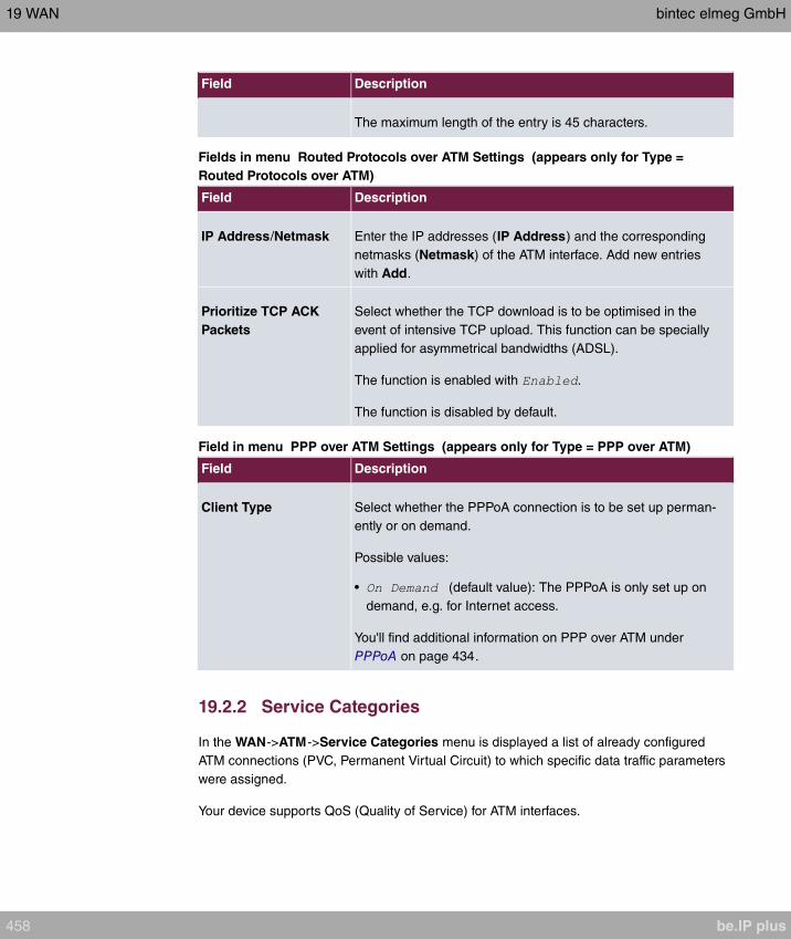
Field Description
The maximum length of the entry is 45 characters.
Fields in menu Routed Protocols over ATM Settings (appears only for Type =
Routed Protocols over ATM)
Field Description
IP Address/Netmask Enter the IP addresses (IP Address) and the corresponding
netmasks (Netmask) of the ATM interface. Add new entries
with Add.
Prioritize TCP ACK
Packets
Select whether the TCP download is to be optimised in the
event of intensive TCP upload. This function can be specially
applied for asymmetrical bandwidths (ADSL).
The function is enabled with .
The function is disabled by default.
Field in menu PPP over ATM Settings (appears only for Type = PPP over ATM)
Field Description
Client Type Select whether the PPPoA connection is to be set up perman-
ently or on demand.
Possible values:
• (default value): The PPPoA is only set up on
demand, e.g. for Internet access.
You'll find additional information on PPP over ATM under
PPPoA on page 434.
19.2.2 Service Categories
In the WAN->ATM->Service Categories menu is displayed a list of already configured
ATM connections (PVC, Permanent Virtual Circuit) to which specific data traffic parameters
were assigned.
Your device supports QoS (Quality of Service) for ATM interfaces.
19 WAN bintec elmeg GmbH
458 be.IP plus

Caution
ATM QoS should only be used if your provider specifies a list of data traffic parameters
(traffic contract).
The configuration of ATM QoS requires extensive knowledge of ATM technology and
the way the bintec elmegbintec elmeg devices function. An incorrect configuration can
cause considerable disruption during operation. If applicable, save the original config-
uration on your PC.
19.2.2.1 New
Choose the New button to create additional categories.
The menu WAN->ATM->Service Categories->New consists of the following fields:
Fields in the Basic Parameters menu.
Field Description
Virtual Channel Con-
nection (VCC)
Select the already configured ATM connection (displayed by the
combination of VPI and VCI) for which the service category is to
be defined.
ATM Service Category Select how the data traffic of the ATM connection is to be con-
trolled.
A priority is implicitly assigned when you select the ATM service
category: from CBR (highest priority) through VBR.1 /VBR.3 to
VBR (lowest priority).
Possible settings:
• (default value): No spe-
cific data rate is guaranteed for the connection. The Peak Cell
Rate (PCR) specifies the limit above which data is discarded.
This category is suitable for non-critical applications.
• : (Constant Bit Rate) The con-
nection is assigned a guaranteed data rate determined by the
Peak Cell Rate (PCR). This category is suitable for critical
(real-time) applications that require a guaranteed data rate.
• : A guaranteed data
rate is assigned to the connection - Sustained Cell Rate
(SCR). This may be exceeded by the volume configured in
Maximum Burst Size (MBS). Any additional ATM traffic is
bintec elmeg GmbH 19 WAN
be.IP plus 459

Field Description
discarded. The Peak Cell Rate (PCR) constitutes the maxim-
um possible data rate. This category is suitable for non-critical
applications with burst data traffic.
• : A guaranteed data
rate is assigned to the connection - Sustained Cell Rate
(SCR). This may be exceeded by the volume configured in
Maximum Burst Size (MBS). Additional ATM traffic is
marked and handled with low priority based on the utilisation
of the destination network, i.e. is discarded if necessary. The
Peak Cell Rate (PCR) constitutes the maximum possible data
rate. This category is suitable for critical applications with
burst data traffic.
Peak Cell Rate (PCR) Enter a value for the maximum data rate in bits per second.
Possible values: to .
The default value is .
Sustained Cell Rate
(SCR)
Only for ATM Service Category =
or
Enter a value for the minimum available, guaranteed data rate
in bits per second.
Possible values: to .
The default value is .
Maximum Burst Size
(MBS)
Only for ATM Service Category =
or
Enter a value for the maximum number of bits per second by
which the PCR can be exceeded briefly.
Possible values: to .
The default value is .
19 WAN bintec elmeg GmbH
460 be.IP plus

19.2.3 OAM Controlling
OAM is a service for monitoring ATM connections. A total of five hierarchies (flow level F1
to F5) are defined for OAM information flow. The most important information flows for an
ATM connection are F4 and F5. The F4 information flow concerns the virtual path (VP) and
the F5 information flow the virtual channel (VC). The VP is defined by the VPI value, the
VC by VPI and VCI.
Note
Generally, monitoring is not carried out by the terminal but is initiated by the ISP. Your
device then only needs to react correctly to the signals received. This is ensured
without a specific OAM configuration for both flow level 4 and flow level 5.
Two mechanisms are available for monitoring the ATM connection: Loopback Tests and
OAM Continuity Check (OAM CC). These can be configured independently of each other.
Caution
The configuration of OAM requires extensive knowledge of ATM technology and the
way the bintec elmegbintec elmeg devices functions. An incorrect configuration can
cause considerable disruption during operation. If applicable, save the original config-
uration on your PC.
In the WAN->ATM->OAM Controlling menu, a list of all monitored OAM flow levels is dis-
played.
19.2.3.1 New
Choose the New button to set up monitoring for other flow levels.
The menu WAN->ATM->OAM Controlling->New consists of the following fields:
Fields in the OAM Flow Configuration menu.
Field Description
OAM Flow Level Select the OAM flow level to be monitored.
Possible values:
• : (virtual channel level) The OAM settings are used for the
bintec elmeg GmbH 19 WAN
be.IP plus 461
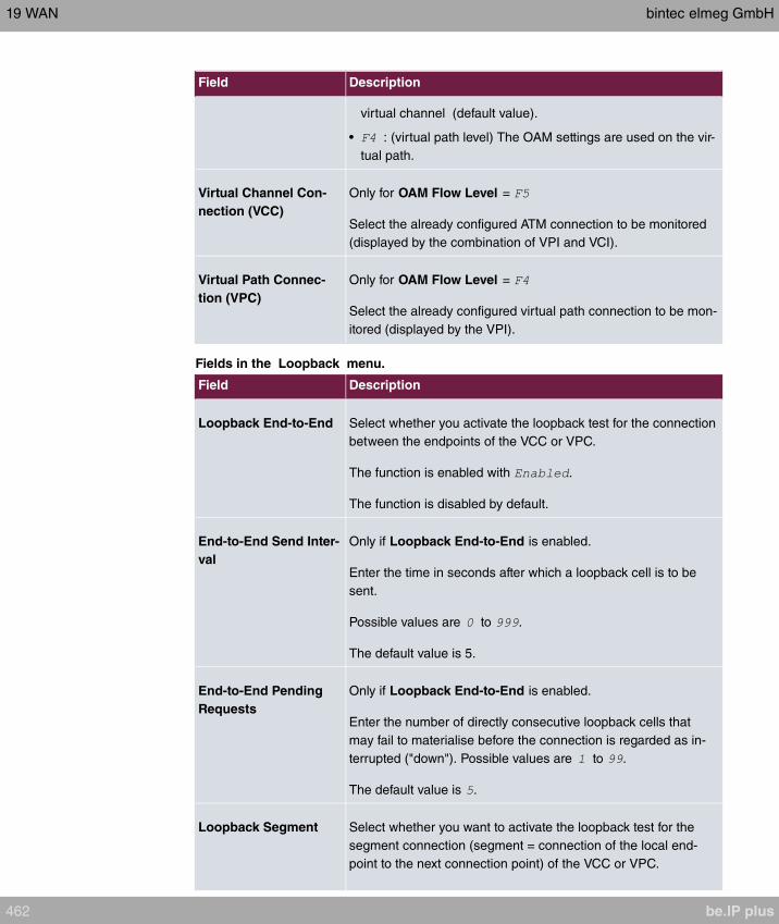
Field Description
virtual channel (default value).
• : (virtual path level) The OAM settings are used on the vir-
tual path.
Virtual Channel Con-
nection (VCC)
Only for OAM Flow Level =
Select the already configured ATM connection to be monitored
(displayed by the combination of VPI and VCI).
Virtual Path Connec-
tion (VPC)
Only for OAM Flow Level =
Select the already configured virtual path connection to be mon-
itored (displayed by the VPI).
Fields in the Loopback menu.
Field Description
Loopback End-to-End Select whether you activate the loopback test for the connection
between the endpoints of the VCC or VPC.
The function is enabled with .
The function is disabled by default.
End-to-End Send Inter-
val
Only if Loopback End-to-End is enabled.
Enter the time in seconds after which a loopback cell is to be
sent.
Possible values are to .
The default value is 5.
End-to-End Pending
Requests
Only if Loopback End-to-End is enabled.
Enter the number of directly consecutive loopback cells that
may fail to materialise before the connection is regarded as in-
terrupted ("down"). Possible values are to .
The default value is .
Loopback Segment Select whether you want to activate the loopback test for the
segment connection (segment = connection of the local end-
point to the next connection point) of the VCC or VPC.
19 WAN bintec elmeg GmbH
462 be.IP plus

Field Description
The function is enabled with .
The function is disabled by default.
Segment Send Interval Only if Loopback Segment is enabled.
Enter the time in seconds after which a loopback cell is sent.
Possible values are to .
The default value is .
Segment Pending Re-
quests
Only if Loopback Segment is enabled.
Enter the number of directly consecutive loopback cells that
may fail to materialise before the connection is regarded as in-
terrupted ("down").
Possible values are to .
The default value is .
Fields in the CC Activation menu.
Field Description
Continuity Check (CC)
End-to-End
Select whether you activate the OAM-CC test for the connection
between the endpoints of the VCC or VPC.
Possible values:
• (default value): OAM CC requests are responded
to after CC negotiation (CC activation negotiation).
• : OAM CC requests are sent after CC negotiation (CC
activation negotiation).
• : OAM CC requests are sent and answered after CC ne-
gotiation (CC activation negotiation).
• : Depending on the setting in the Direction
field, OAM CC requests are either sent and/or responded to.
There is no CC negotiation.
• : The function is disabled.
Also select whether the test cells of the OAM CC are to be sent
or received.
bintec elmeg GmbH 19 WAN
be.IP plus 463

Field Description
Possible values:
• (default value): CC data is both received and gener-
ated.
• : CC data is received.
• : CC data is generated.
Continuity Check (CC)
Segment
Select whether you want to activate the OAM-CC test for the
segment connection (segment = connection of the local end-
point to the next connection point) of the VCC or VPC.
Possible values:
• (default value): OAM CC requests are responded
to after CC negotiation (CC activation negotiation).
• : OAM CC requests are sent after CC negotiation (CC
activation negotiation).
• : OAM CC requests are sent and answered after CC ne-
gotiation (CC activation negotiation).
• : Depending on the setting in the Direction
field, OAM CC requests are either sent and/or responded to.
There is no CC negotiation.
• : The function is disabled.
Also select whether the test cells of the OAM CC are to be sent
or received.
Possible settings:
• (default value): CC data is both received and gener-
ated.
• : CC data is received.
• : CC data is generated.
19.3 Real Time Jitter Control
When telephoning over the Internet, voice data packets normally have the highest priority.
Nevertheless, if the upstream bandwidth is low, noticeable delays in voice transmission can
occur when other packets are routed at the same time.
The real time jitter control function solves this problem. So that the "line" is not blocked for
19 WAN bintec elmeg GmbH
464 be.IP plus

too long for the voice data packets, the size of the other packets can be reduced, if re-
quired, during a telephone call.
19.3.1 Controlled Interfaces
In the WAN->Real Time Jitter Control->Controlled Interfaces a list of functions is dis-
played for which the Real Time Jitter Control function is configured.
19.3.1.1 New
Click the New button to optimise voice transmission for other interfaces.
The menu WAN->Real Time Jitter Control->Controlled Interfaces->New consists of the
following fields:
Fields in the Basic Settings menu.
Field Description
Interface Define for which interfaces voice transmission is to be optim-
ised.
Control Mode Select the mode for the optimisation.
Possible values:
• (default value): By
means of the data routed via the media gateway, the system
detects voice data traffic and optimises the voice transmis-
sion.
• : All RTP streams are optimised.
• : Voice data transmission is not optimised.
• : Voice data transmission is always optimised.
Maximum Upload
Speed
Enter the maximum available upstream bandwidth in kbp/s for
the selected interface.
bintec elmeg GmbH 19 WAN
be.IP plus 465
Chapter 20 VPN
A connection that uses the Internet as a "transport medium" but is not publicly accessible is
referred to as a VPN (Virtual Private Network). Only authorised users have access to such
a VPN, which is seemingly also referred to as a VPN tunnel. Normally the data transported
over a VPN is encrypted.
A VPN allows field staff or staff working from home offices to access data on the company's
network. Subsidiaries can also connect to head office over VPN.
The connection partner is authenticated with a password, using preshared keys or certific-
ates.
With IPSec the data is encrypted using AES or 3DES, for example.
20.1 IPSec
IPSec enables secure connections to be set up between two locations (VPN). This enables
sensitive business data to be transferred via an unsecure medium such as the Internet.
The devices used function here as the endpoints of the VPN tunnel. IPSec involves a num-
ber of Internet Engineering Task Force (IETF) standards, which specify mechanisms for the
protection and authentication of IP packets. IPSec offers mechanisms for encrypting and
decrypting the data transferred in the IP packets. The IPSec implementation can also be
smoothly integrated in a Public Key Infrastructure (PKI, see Certificates on page 83). IPSec
implementation achieves this firstly by using the Authentication Header (AH) protocol and
Encapsulated Security Payload (ESP) protocol and secondly through the use of crypto-
graphic key administration mechanisms like the Internet Key Exchange (IKE) protocol.
Additional IPv4 Traffic Filter
bintec elmeg gateways support two different methods of setting up IPSec connections:
• a method based on policies and
• a method based on routing.
The policy-based method uses data traffic filters to negotiate the IPSec phase 2 SAs. This
allows for a very "fine-grained" filter to be applied to the IP packet, even at the level of the
protocol and the port.
The routing-based method offers various advantages over the policy-based method, e.g.,
NAT/PAT within a tunnel, IPSec in combination with routing protocols and the creation of
VPN backup scenarios. With the routing-based method, the configured or dynamically
20 VPN bintec elmeg GmbH
466 be.IP plus

learned routes are used to negotiate the IPSec phase 2 SAs. Although this method does
simplify many configurations, problems may also be caused by competing routes or the
"coarser" filtering of data traffic.
The Additional IPv4 Traffic Filter parameter fixes this problem. You can apply a "finer" fil-
ter, i.e. you can enter the source IP address or the source port. If a Additional IPv4 Traffic
Filter is configured, this is used to negotiate the IPSec phase 2 SAs; the route now only
determines which data traffic is to be routed.
If an IP packet does not match the defined Additional IPv4 Traffic Filter , it is rejected.
If an IP packet meets the requirements in an Additional IPv4 Traffic Filter , IPSec phase 2
negotiation begins and data traffic is transferred over the tunnel.
Note
The parameter Additional IPv4 Traffic Filter is exclusively relevant for the initiator of
the IPSec connection, it is only used for outgoing traffic.
Note
Please note that the phase 2 policies must be configured identically on both of the
IPSec tunnel endpoints.
20.1.1 IPSec Peers
An endpoint of a communication is defined as peer in a computer network. Each peer of-
fers its services and uses the services of other peers.
A list of all configured IPSec Peers is sorted by priority displayed in the
VPN->IPSec->IPSec Peers menu.
Peer Monitoring
The menu for monitoring a peer is called by selecting the button for the peer in the peer
list. See Values in the IPSec Tunnels list on page 639.
20.1.1.1 New
Choose the New button to set up more IPSec peers.
bintec elmeg GmbH 20 VPN
be.IP plus 467
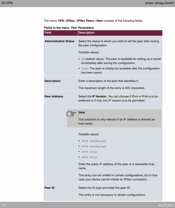
The menu VPN->IPSec->IPSec Peers->New consists of the following fields:
Fields in the menu Peer Parameters
Field Description
Administrative Status Select the status to which you wish to set the peer after saving
the peer configuration.
Possible values:
• (default value): The peer is available for setting up a tunnel
immediately after saving the configuration.
• : The peer is initially not available after the configuration
has been saved.
Description Enter a description of the peer that identifies it.
The maximum length of the entry is 255 characters.
Peer Address Select the IP Version. You can choose if IPv4 or IPv6 is to be
preferred or if only one IP version is to be permitted.
Note
This selection is only relevant if an IP address is entered as
host name.
Possible values:
•
•
•
•
Enter the public IP address of the peer or a resolvable host
name.
This entry can be omitted in certain configurations, but in that
case your device cannot initiate an IPSec connection.
Peer ID Select the ID type and enter the peer ID.
This entry is not necessary in certain configurations.
20 VPN bintec elmeg GmbH
468 be.IP plus
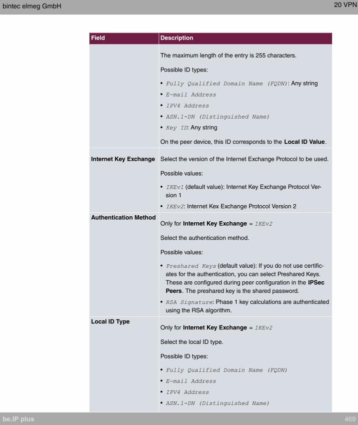
Field Description
The maximum length of the entry is 255 characters.
Possible ID types:
• : Any string
•
•
•
• : Any string
On the peer device, this ID corresponds to the Local ID Value.
Internet Key Exchange Select the version of the Internet Exchange Protocol to be used.
Possible values:
• (default value): Internet Key Exchange Protocol Ver-
sion 1
• : Internet Kex Exchange Protocol Version 2
Authentication MethodOnly for Internet Key Exchange =
Select the authentication method.
Possible values:
• (default value): If you do not use certific-
ates for the authentication, you can select Preshared Keys.
These are configured during peer configuration in the IPSec
Peers. The preshared key is the shared password.
• : Phase 1 key calculations are authenticated
using the RSA algorithm.
Local ID TypeOnly for Internet Key Exchange =
Select the local ID type.
Possible ID types:
•
•
•
•
bintec elmeg GmbH 20 VPN
be.IP plus 469

Field Description
• : Any string
Local IDOnly for Internet Key Exchange =
Enter the ID of your device.
For Authentication Method = or
the option Use Subject Name from certificate is dis-
played.
When you enable the option Use Subject Name from certific-
ate, the subject name indicated in the certificate is used.
Preshared Key Enter the password agreed with the peer.
The maximum length of the entry is 50 characters. All charac-
ters are possible except for at the start of the entry.
IP Version of the
tunneled Networks Select if IPv4, IPv6 or both versions are allowed for the VPN
tunnel.
Possible values:
•
•
•
Fields in the menu IPv4 Interface Routes
Field Description
Security PolicySelect the security settings to be used with the interface.
Possible values:
• : All IP packets are allowed through except for
those which are explicitly prohibited.
• (default value): Only those packets are transmit-
ted that can be attributed to a connection that has been initi-
ated from a trusted zone.
You can configure exceptions for the selected setting in the
Firewall on page 518 menu.
20 VPN bintec elmeg GmbH
470 be.IP plus
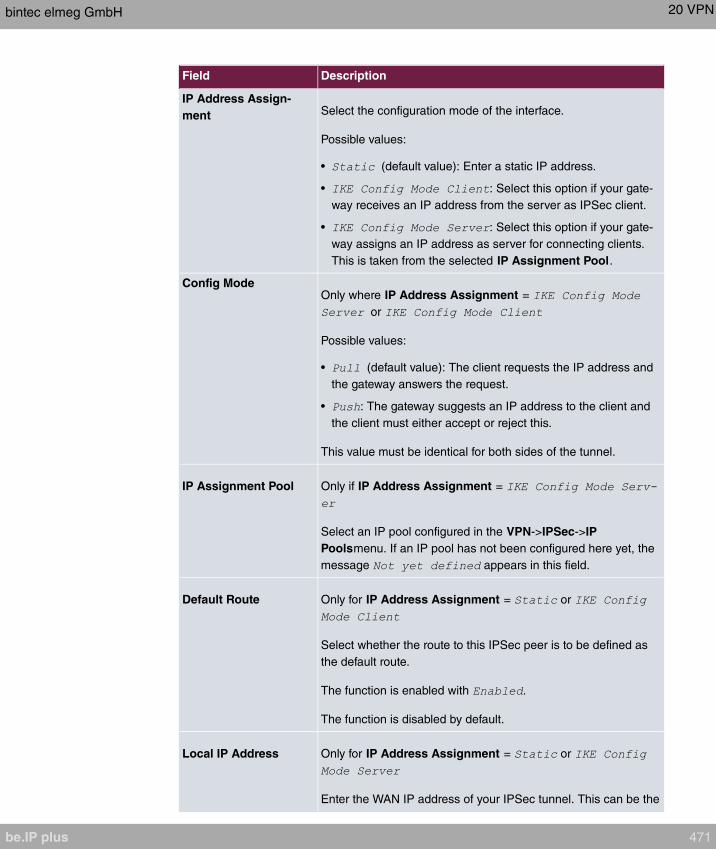
Field Description
IP Address Assign-
ment Select the configuration mode of the interface.
Possible values:
• (default value): Enter a static IP address.
• : Select this option if your gate-
way receives an IP address from the server as IPSec client.
• : Select this option if your gate-
way assigns an IP address as server for connecting clients.
This is taken from the selected IP Assignment Pool.
Config ModeOnly where IP Address Assignment =
or
Possible values:
• (default value): The client requests the IP address and
the gateway answers the request.
• : The gateway suggests an IP address to the client and
the client must either accept or reject this.
This value must be identical for both sides of the tunnel.
IP Assignment Pool Only if IP Address Assignment =
Select an IP pool configured in the VPN->IPSec->IP
Poolsmenu. If an IP pool has not been configured here yet, the
message appears in this field.
Default Route Only for IP Address Assignment = or
Select whether the route to this IPSec peer is to be defined as
the default route.
The function is enabled with .
The function is disabled by default.
Local IP Address Only for IP Address Assignment = or
Enter the WAN IP address of your IPSec tunnel. This can be the
bintec elmeg GmbH 20 VPN
be.IP plus 471

Field Description
same IP address as the address configured on your router as
the LAN IP address.
MetricOnly for IP Address Assignment = or
and Default Route =
Select the priority of the route.
The lower the value, the higher the priority of the route.
Value range from to . The default value is .
Route Entries Only for IP Address Assignment = or
Define routing entries for this connection partner.
• : IP address of the destination host or
LAN.
• : Netmask for .
• : The lower the value, the higher the priority of the
route (possible values ). The default value is .
Fields in the menu Additional IPv4 Traffic Filter
Field Description
Additional IPv4 Traffic
Filter
Only for Internet Key Exchange =
Use Add to create a new filter.
Fields in the IPv6 Interface Routes menu
Field Description
Security Policy Select the security settings to be used with the interface..
Possible values:
• : IP packets are only allowed through if the con-
nection has been initiated from "inside".
We recommend you use this setting if you want to use IPv6
outside of your LAN.
• (default value): All IP packets are allowed through
except for those which are explicitly prohibited.
20 VPN bintec elmeg GmbH
472 be.IP plus

Field Description
We recommend you use this setting if you want to use IPv6
on your LAN.
You can configure exceptions for the selected setting in the
Firewall on page 518 menu.
Local IPv6 NetworkSelect a network. You can choose from the Link Prefixes avial-
bale under LAN->IP Configuration->Interfaces->New.
Enter the Local IPv6 address and the corresponding prefix
length. The default prefix length is /64.This prefix must end with
::.
Remote IPv6 Network Add a new prefix. Enter the address of the other tunnel end-
point. The default prefix Length is and the default Priority is
. The lower the value entered for Priority, the higher the prior-
ity of the route.
Additional data traffic filters
bintec elmeg Gateways support two different methods for establishing IPSec connections:
• a method based on policies and
• a method based on routing.
The policy-based method uses data traffic filters to negotiate the IPSec phase 2 SAs. This
enables the filtering of the IP packets to be very "fine grained" down to protocol and port
level.
The routing-based method offers various advantages over the policy-based method, e.g.,
NAT/PAT within a tunnel, IPSec in combination with routing protocols and the creation of
VPN backup scenarios. With the routing-based method, the configured or dynamically
learned routes are used to negotiate the IPSec phase 2 SAs. While it is true that this meth-
od simplifies many configurations, at the same time there can be problems due to compet-
ing routes or the "coarser" filtering of the data traffic.
The Additional IPv4 Traffic Filter parameter fixes this problem. You can filter more
"finely", i. e. you can, e. g., specify the source IP address or the source port. If there is a
Additional IPv4 Traffic Filter configured, it is used to negotiate the IPSec phase 2 SAs;
the route only determines which data traffic is to be routed.
If an IP packet does not match the defined Additional IPv4 Traffic Filter it is discarded.
If an IP packet meets the requirements in an Additional IPv4 Traffic Filter , IPSec phase 2
bintec elmeg GmbH 20 VPN
be.IP plus 473

negotiation begins and data traffic is transferred over the tunnel.
Note
The parameter Additional IPv4 Traffic Filter is only relevant to the initiator of the
IPSec connection, it only applies to outgoing data traffic.
Note
Please note that the phase 2 policies must be configured identically on both of the
IPSec tunnel endpoints.
Add new entries with Add.
Fields in the menu Basic Parameters
Field Description
Description Enter a description for the filter.
Protocol Select a protocol. The option (default value) matches all
protocols.
Source IP Address/
Netmask
Enter, if required, the source IP address and netmask of the
data packets.
Possible values:
•
• : Enter the IP address of the host.
• (default value): Enter the network address and the
related netmask.
Source Port Only for Protocol = or
Enter the source port of the data packets. The default setting
(= -1) means that the port remains unspecified.
Destination IP Ad-
dress/Netmask
Enter the destination IP address and corresponding netmask of
the data packets.
Destination Port Only for Protocol = or
20 VPN bintec elmeg GmbH
474 be.IP plus

Field Description
Enter the destination port of the data packets. The default set-
ting (= -1) means that the port remains unspecified.
The menu Advanced Settings consists of the following fields:
Fields in the menu Advanced IPSec Options
Field Description
Phase-1 Profile Select a profile for Phase 1. Besides user-defined profiles, pre-
defined profiles are available.
Possible values:
• : Uses the profile marked
as standard in VPN->IPSec->Phase-1 Profiles
• : Uses a special profile which contains the
proposals for Phase 1 3DES/MD5, AES/MD5 and Blowfish/
MD5 regardless of the proposal selection in menu
VPN->IPSec->Phase-1 Profiles.
• : Uses a profile configured in menu
VPN->IPSec->Phase-1 Profiles for Phase 1.
Phase-2 Profile Select a profile for Phase 2. Besides user-defined profiles, pre-
defined profiles are available.
Possible values:
• : Uses the profile marked
as standard in VPN->IPSec->Phase-2 Profiles
• : Uses a special profile which contains the
proposals for Phase 2 3DES/MD5, AES-128/MD5 and Blow-
fish/MD5 regardless of the proposal selection in menu
VPN->IPSec->Phase-2 Profiles.
• : Uses a profile configured in menu
VPN->IPSec->Phase-2 Profiles for Phase 2.
XAUTH Profile Select a profile created in VPN->IPSec->XAUTH Profiles if you
wish to use this IPSec peer XAuth for authentication.
If XAuth is used together with IKE Config Mode, the transac-
tions for XAuth are carried out before the transactions for IKE
Config Mode.
bintec elmeg GmbH 20 VPN
be.IP plus 475
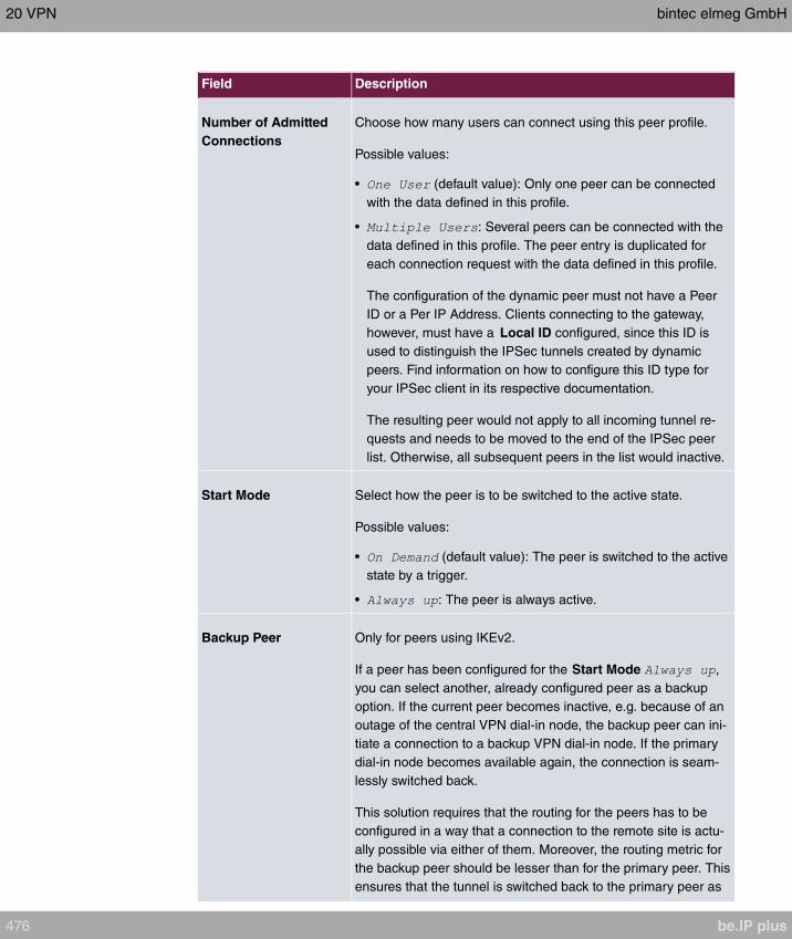
Field Description
Number of Admitted
Connections
Choose how many users can connect using this peer profile.
Possible values:
• (default value): Only one peer can be connected
with the data defined in this profile.
• : Several peers can be connected with the
data defined in this profile. The peer entry is duplicated for
each connection request with the data defined in this profile.
The configuration of the dynamic peer must not have a Peer
ID or a Per IP Address. Clients connecting to the gateway,
however, must have a Local ID configured, since this ID is
used to distinguish the IPSec tunnels created by dynamic
peers. Find information on how to configure this ID type for
your IPSec client in its respective documentation.
The resulting peer would not apply to all incoming tunnel re-
quests and needs to be moved to the end of the IPSec peer
list. Otherwise, all subsequent peers in the list would inactive.
Start Mode Select how the peer is to be switched to the active state.
Possible values:
• (default value): The peer is switched to the active
state by a trigger.
• : The peer is always active.
Backup Peer Only for peers using IKEv2.
If a peer has been configured for the Start Mode ,
you can select another, already configured peer as a backup
option. If the current peer becomes inactive, e.g. because of an
outage of the central VPN dial-in node, the backup peer can ini-
tiate a connection to a backup VPN dial-in node. If the primary
dial-in node becomes available again, the connection is seam-
lessly switched back.
This solution requires that the routing for the peers has to be
configured in a way that a connection to the remote site is actu-
ally possible via either of them. Moreover, the routing metric for
the backup peer should be lesser than for the primary peer. This
ensures that the tunnel is switched back to the primary peer as
20 VPN bintec elmeg GmbH
476 be.IP plus

Field Description
soon as its connection is available again.
Delay until returning to
primary peer If in a fallback case the primary peer is coming up again, it may
be desirable to delay the use of the primary peer and thus the
reset of the secondary peer. This option defines the intended
delay time.
Fields in the menu Advanced IP Options
Field Description
Public Interface Specify the public (or WAN) interface that this peer is to use to
connect to its VPN partner. If you select
, the decision as to via which interface the data traffic is
routed is made based on the current routing table. If you select
an interface, the interface is used taking into consideration the
setting under Public Interface Mode.
Public Interface ModeOnly when an interface is selected for Public Interface.
Specify how strictly the setting is handled.
Possible values:
• : Only the selected interface is used, independently
from the priorities in the current routing table.
• : The priorities in the current routing table will be
used. Only if several equivalent routes are available, the route
via the selected interface will be applied.
Public Source IPv4 Ad-
dress If you are operating more than one Internet connection in paral-
lel, here you can specify the public IP address that is to be used
as the source address for the peer's data traffic. Select whether
the Public Source IPv4 Address is to be enabled.
The function is enabled with .
In the input field, enter the public IP address that is to be used
as the sender address.
The function is disabled by default.
Public Source IPv6 Ad-
dress If you are operating more than one Internet connection in paral-
lel, here you can specify the public IP address that is to be used
as the source address for the peer's data traffic. Select whether
bintec elmeg GmbH 20 VPN
be.IP plus 477
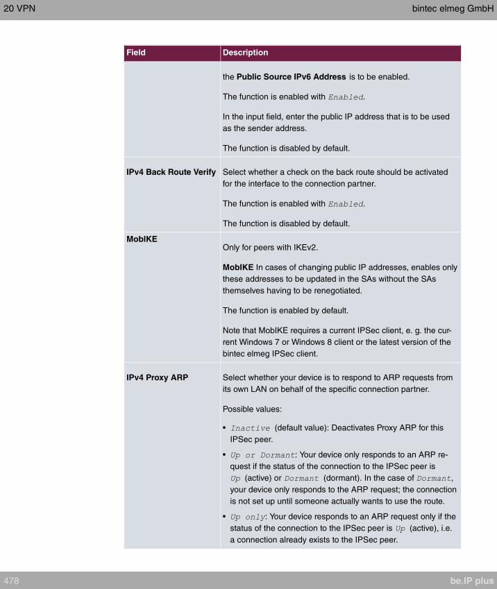
Field Description
the Public Source IPv6 Address is to be enabled.
The function is enabled with .
In the input field, enter the public IP address that is to be used
as the sender address.
The function is disabled by default.
IPv4 Back Route Verify Select whether a check on the back route should be activated
for the interface to the connection partner.
The function is enabled with .
The function is disabled by default.
MobIKEOnly for peers with IKEv2.
MobIKE In cases of changing public IP addresses, enables only
these addresses to be updated in the SAs without the SAs
themselves having to be renegotiated.
The function is enabled by default.
Note that MobIKE requires a current IPSec client, e. g. the cur-
rent Windows 7 or Windows 8 client or the latest version of the
bintec elmeg IPSec client.
IPv4 Proxy ARP Select whether your device is to respond to ARP requests from
its own LAN on behalf of the specific connection partner.
Possible values:
• (default value): Deactivates Proxy ARP for this
IPSec peer.
• : Your device only responds to an ARP re-
quest if the status of the connection to the IPSec peer is
(active) or (dormant). In the case of ,
your device only responds to the ARP request; the connection
is not set up until someone actually wants to use the route.
• : Your device responds to an ARP request only if the
status of the connection to the IPSec peer is (active), i.e.
a connection already exists to the IPSec peer.
20 VPN bintec elmeg GmbH
478 be.IP plus

Field Description
CA Certificates Only available if certificates are in use on the device.
If you enable the Trust the following CA certificates option,
you can select CA certificates that are accepted for this profile.
This option can only be configured if certificates are loaded.
IPSec Callback
bintec elmeg devices support the DynDNS service to enable hosts without fixed IP ad-
dresses to obtain a secure connection over the Internet. This service enables a peer to be
identified using a host name that can be resolved by DNS. You do not need to configure
the IP address of the peer.
The DynDNS service does not signal whether a peer is actually online and cannot cause a
peer to set up an Internet connection to enable an IPSec tunnel over the Internet. This pos-
sibility is created with IPSec callback: Using a direct ISDN call to a peer, you can signal
that you are online and waiting for the peer to set up an IPSec tunnel over the Internet. If
the called peer currently has no connection to the Internet, the ISDN call causes a connec-
tion to be set up. This ISDN call costs nothing (depending on country), as it does not have
to be accepted by your device. The identification of the caller from his or her ISDN number
is enough information to initiate setting up a tunnel.
To set up this service, you must first configure a call number for IPSec callback on the
passive side in the Physical Interfaces->ISDN Ports->MSN Configuration->New menu.
The value is available for this purpose in the field Service. This entry ensures that
incoming calls for this number are routed to the IPSec service.
If callback is active, the peer is caused to initiate setting up an IPSec tunnel by an ISDN
call as soon as this tunnel is required. If callback is set to passive, setting up a tunnel to the
peer is always initiated if an ISDN call is received on the relevant number ( MSN in menu
Physical Interfaces->ISDN Ports->MSN Configuration->New for Service ). This
ensures that both peers are reachable and that the connection can be set up over the Inter-
net. The only case in which callback is not executed is if SAs (Security Associations)
already exist, i.e. the tunnel to the peer already exists.
Note
If a tunnel is to be set up to a peer, the interface over which the tunnel is to be imple-
mented is activated first by the IPSec Daemon. If IPSec with DynDNS is configured on
the local device, the own IP address is propagated first and then the ISDN call is sent
to the remote device. This ensures that the remote device can actually reach the local
device if it initiates the tunnel setup.
bintec elmeg GmbH 20 VPN
be.IP plus 479
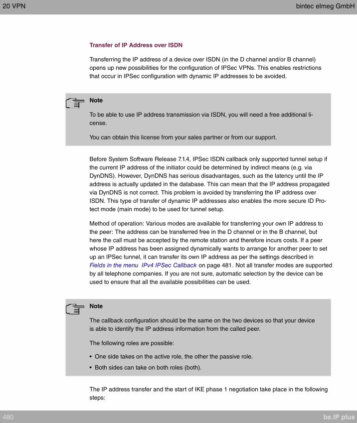
Transfer of IP Address over ISDN
Transferring the IP address of a device over ISDN (in the D channel and/or B channel)
opens up new possibilities for the configuration of IPSec VPNs. This enables restrictions
that occur in IPSec configuration with dynamic IP addresses to be avoided.
Note
To be able to use IP address transmission via ISDN, you will need a free additional li-
cense.
You can obtain this license from your sales partner or from our support.
Before System Software Release 7.1.4, IPSec ISDN callback only supported tunnel setup if
the current IP address of the initiator could be determined by indirect means (e.g. via
DynDNS). However, DynDNS has serious disadvantages, such as the latency until the IP
address is actually updated in the database. This can mean that the IP address propagated
via DynDNS is not correct. This problem is avoided by transferring the IP address over
ISDN. This type of transfer of dynamic IP addresses also enables the more secure ID Pro-
tect mode (main mode) to be used for tunnel setup.
Method of operation: Various modes are available for transferring your own IP address to
the peer: The address can be transferred free in the D channel or in the B channel, but
here the call must be accepted by the remote station and therefore incurs costs. If a peer
whose IP address has been assigned dynamically wants to arrange for another peer to set
up an IPSec tunnel, it can transfer its own IP address as per the settings described in
Fields in the menu IPv4 IPSec Callback on page 481. Not all transfer modes are supported
by all telephone companies. If you are not sure, automatic selection by the device can be
used to ensure that all the available possibilities can be used.
Note
The callback configuration should be the same on the two devices so that your device
is able to identify the IP address information from the called peer.
The following roles are possible:
• One side takes on the active role, the other the passive role.
• Both sides can take on both roles (both).
The IP address transfer and the start of IKE phase 1 negotiation take place in the following
steps:
20 VPN bintec elmeg GmbH
480 be.IP plus
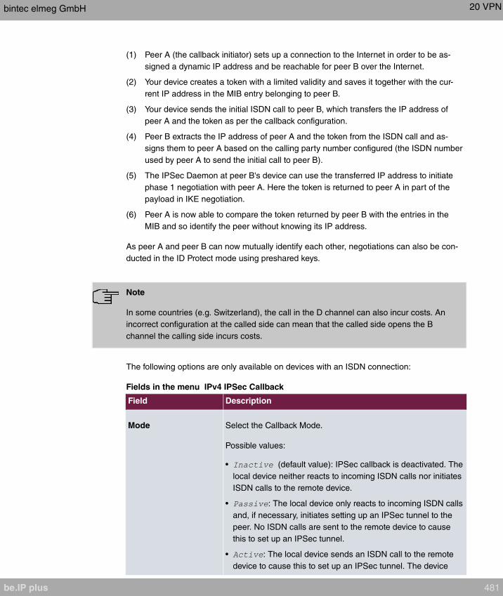
(1) Peer A (the callback initiator) sets up a connection to the Internet in order to be as-
signed a dynamic IP address and be reachable for peer B over the Internet.
(2) Your device creates a token with a limited validity and saves it together with the cur-
rent IP address in the MIB entry belonging to peer B.
(3) Your device sends the initial ISDN call to peer B, which transfers the IP address of
peer A and the token as per the callback configuration.
(4) Peer B extracts the IP address of peer A and the token from the ISDN call and as-
signs them to peer A based on the calling party number configured (the ISDN number
used by peer A to send the initial call to peer B).
(5) The IPSec Daemon at peer B's device can use the transferred IP address to initiate
phase 1 negotiation with peer A. Here the token is returned to peer A in part of the
payload in IKE negotiation.
(6) Peer A is now able to compare the token returned by peer B with the entries in the
MIB and so identify the peer without knowing its IP address.
As peer A and peer B can now mutually identify each other, negotiations can also be con-
ducted in the ID Protect mode using preshared keys.
Note
In some countries (e.g. Switzerland), the call in the D channel can also incur costs. An
incorrect configuration at the called side can mean that the called side opens the B
channel the calling side incurs costs.
The following options are only available on devices with an ISDN connection:
Fields in the menu IPv4 IPSec Callback
Field Description
Mode Select the Callback Mode.
Possible values:
• (default value): IPSec callback is deactivated. The
local device neither reacts to incoming ISDN calls nor initiates
ISDN calls to the remote device.
• : The local device only reacts to incoming ISDN calls
and, if necessary, initiates setting up an IPSec tunnel to the
peer. No ISDN calls are sent to the remote device to cause
this to set up an IPSec tunnel.
• : The local device sends an ISDN call to the remote
device to cause this to set up an IPSec tunnel. The device
bintec elmeg GmbH 20 VPN
be.IP plus 481
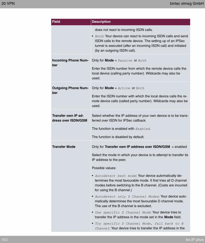
Field Description
does not react to incoming ISDN calls.
• : Your device can react to incoming ISDN calls and send
ISDN calls to the remote device. The setting up of an IPSec
tunnel is executed (after an incoming ISDN call) and initiated
(by an outgoing ISDN call).
Incoming Phone Num-
ber
Only for Mode = or
Enter the ISDN number from which the remote device calls the
local device (calling party number). Wildcards may also be
used.
Outgoing Phone Num-
ber
Only for Mode = or
Enter the ISDN number with which the local device calls the re-
mote device calls (called party number). Wildcards may also be
used.
Transfer own IP ad-
dress over ISDN/GSM
Select whether the IP address of your own device is to be trans-
ferred over ISDN for IPSec callback.
The function is enabled with .
The function is disabled by default.
Transfer Mode Only for Transfer own IP address over ISDN/GSM = enabled
Select the mode in which your device is to attempt to transfer its
IP address to the peer.
Possible values:
• : Your device automatically de-
termines the most favourable mode. It first tries all D channel
modes before switching to the B channel. (Costs are incurred
for using the B channel.)
• : Your device auto-
matically determines the most favourable D channel mode.
The use of the B channel is excluded.
• : Your device tries to
transfer the IP address in the mode set in the Mode field.
•
: Your device tries to transfer the IP address in the
20 VPN bintec elmeg GmbH
482 be.IP plus

Field Description
mode set in the Mode field. If this does not succeed, the IP
address is transferred in the B channel. (This incurs costs.)
• : Your device transfers the IP
address in the B channel. This incurs costs.
D Channel Mode Only for Transfer Mode =
or
Select the D channel mode in which your device tries to transfer
the IP address.
Possible values:
• (default value): The IP address is transferred in the "LLC
information elements" of the D channel.
• : The IP address is transferred in the subaddress "in-
formation elements" of the D channel.
• : The IP address is transferred in both the
"LLC" and "subaddress information elements".
20.1.2 Phase-1 Profiles
A list of all configured tunnel profiles is displayed in the VPN->IPSec->Phase-1 Profiles
menu.
In the Default column, you can mark the profile to be used as the default profile.
20.1.2.1 New
Choose the Create new IKEv1 Profile or Create new IKEv2 Profile button to create addi-
tional profiles.
The menu VPN->IPSec->Phase-1 Profiles->Create new IKEv1 Profile consists of the fol-
lowing fields:
Fields in the Phase-1 (IKE) Parameters / Phase-1 (IKEv2) Parameters menu.
Field Description
Description Enter a description that uniquely defines the type of rule.
Proposals In this field, you can select any combination of encryption and
bintec elmeg GmbH 20 VPN
be.IP plus 483

Field Description
message hash algorithms for IKE phase 1 on your device. The
combination of six encryption algorithms and four message
hash algorithms gives 24 possible values in this field. At least
one proposal must exist. Therefore the first line of the table can-
not be deactivated.
Encryption algorithms (Encryption):
• : 3DES is an extension of the DES algorithm with an ef-
fective key length of 112 bits, which is rated as secure. It is
the slowest algorithm currently supported.
• : Twofish was a final candidate for the AES
(Advanced Encryption Standard). It is rated as just as secure
as Rijndael (AES), but is slower.
• : Blowfish is a very secure and fast algorithm.
Twofish can be regarded as the successor to Blowfish.
• : CAST is also a very secure algorithm, marginally
slower than Blowfish, but faster than 3DES.
• : DES is an older encryption algorithm, which is rated as
weak due to its small effective length of 56 bits.
• (default value): Rijndael has been nominated as AES
due to its fast key setup, low memory requirements, high level
of security against attacks and general speed. The partner's
AES key length is used here. If this has also selected the
parameter , a key length of 128 bits is used.
• : Rijndael has been nominated as AES due to its
fast key setup, low memory requirements, high level of secur-
ity against attacks and general speed. Here, it is used with a
key length of 128 bits.
• : Rijndael has been nominated as AES due to its
fast key setup, low memory requirements, high level of secur-
ity against attacks and general speed. Here, it is used with a
key length of 192 bits.
• : Rijndael has been nominated as AES due to its
fast key setup, low memory requirements, high level of secur-
ity against attacks and general speed. Here, it is used with a
key length of 256 bits.
Hash algorithms (Authentication):
• : MD5 (Message Digest #5) is an older hash algorithm. It
20 VPN bintec elmeg GmbH
484 be.IP plus
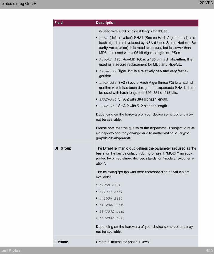
Field Description
is used with a 96 bit digest length for IPSec.
• (default value): SHA1 (Secure Hash Algorithm #1) is a
hash algorithm developed by NSA (United States National Se-
curity Association). It is rated as secure, but is slower than
MD5. It is used with a 96 bit digest length for IPSec.
• : RipeMD 160 is a 160 bit hash algorithm. It is
used as a secure replacement for MD5 and RipeMD.
• : Tiger 192 is a relatively new and very fast al-
gorithm.
• : SH2 (Secure Hash Algorithmus #2) is a hash al-
gorithm which has been designed to supersede SHA 1. It can
be used with hash lengths of 256, 384 or 512 bits.
• : SHA-2 with 384 bit hash length.
• : SHA-2 with 512 bit hash length.
Depending on the hardware of your device some options may
not be available.
Please note that the quality of the algorithms is subject to relat-
ive aspects and may change due to mathematical or crypto-
graphic developments.
DH Group The Diffie-Hellman group defines the parameter set used as the
basis for the key calculation during phase 1. "MODP" as sup-
ported by bintec elmeg devices stands for "modular exponenti-
ation".
The following groups with their corresponding bit values are
available:
•
•
•
•
•
•
Depending on the hardware of your device some options may
not be available.
Lifetime Create a lifetime for phase 1 keys.
bintec elmeg GmbH 20 VPN
be.IP plus 485
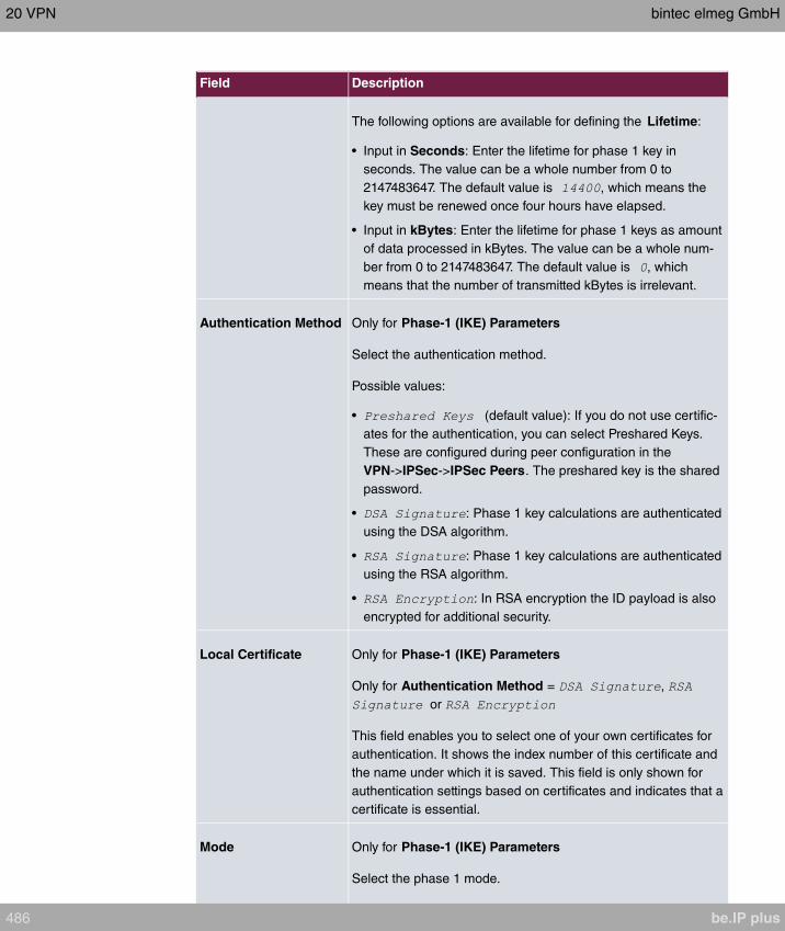
Field Description
The following options are available for defining the Lifetime:
• Input in Seconds: Enter the lifetime for phase 1 key in
seconds. The value can be a whole number from 0 to
2147483647. The default value is , which means the
key must be renewed once four hours have elapsed.
• Input in kBytes: Enter the lifetime for phase 1 keys as amount
of data processed in kBytes. The value can be a whole num-
ber from 0 to 2147483647. The default value is , which
means that the number of transmitted kBytes is irrelevant.
Authentication Method Only for Phase-1 (IKE) Parameters
Select the authentication method.
Possible values:
• (default value): If you do not use certific-
ates for the authentication, you can select Preshared Keys.
These are configured during peer configuration in the
VPN->IPSec->IPSec Peers. The preshared key is the shared
password.
• : Phase 1 key calculations are authenticated
using the DSA algorithm.
• : Phase 1 key calculations are authenticated
using the RSA algorithm.
• : In RSA encryption the ID payload is also
encrypted for additional security.
Local Certificate Only for Phase-1 (IKE) Parameters
Only for Authentication Method = ,
or
This field enables you to select one of your own certificates for
authentication. It shows the index number of this certificate and
the name under which it is saved. This field is only shown for
authentication settings based on certificates and indicates that a
certificate is essential.
Mode Only for Phase-1 (IKE) Parameters
Select the phase 1 mode.
20 VPN bintec elmeg GmbH
486 be.IP plus
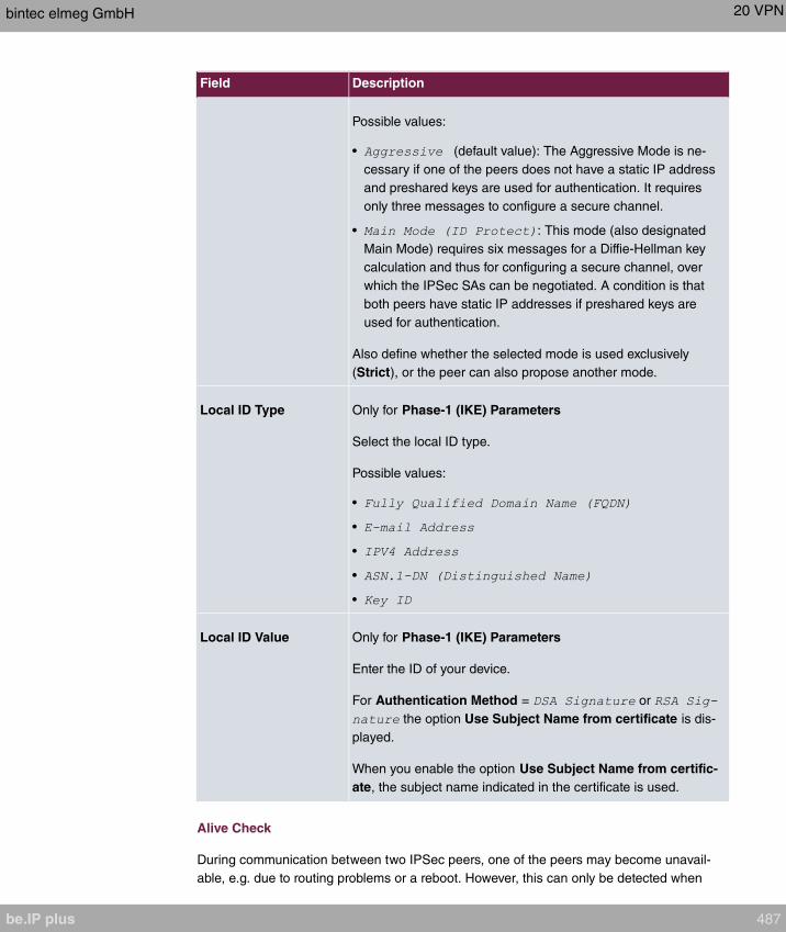
Field Description
Possible values:
• (default value): The Aggressive Mode is ne-
cessary if one of the peers does not have a static IP address
and preshared keys are used for authentication. It requires
only three messages to configure a secure channel.
• : This mode (also designated
Main Mode) requires six messages for a Diffie-Hellman key
calculation and thus for configuring a secure channel, over
which the IPSec SAs can be negotiated. A condition is that
both peers have static IP addresses if preshared keys are
used for authentication.
Also define whether the selected mode is used exclusively
(Strict), or the peer can also propose another mode.
Local ID Type Only for Phase-1 (IKE) Parameters
Select the local ID type.
Possible values:
•
•
•
•
•
Local ID Value Only for Phase-1 (IKE) Parameters
Enter the ID of your device.
For Authentication Method = or
the option Use Subject Name from certificate is dis-
played.
When you enable the option Use Subject Name from certific-
ate, the subject name indicated in the certificate is used.
Alive Check
During communication between two IPSec peers, one of the peers may become unavail-
able, e.g. due to routing problems or a reboot. However, this can only be detected when
bintec elmeg GmbH 20 VPN
be.IP plus 487

the end of the lifetime of the security connection is reached. Up until this point the data
packets are lost. These are various methods of performing an alive check to prevent this
happening. In the Alive Check field you can specify whether a method should be used to
check the availability of a peer.
Two methods are available: Heartbeats and Dead Peer Detection.
The menu Advanced Settings consists of the following fields:
Fields in the Advanced Settings menu.
Field Description
Alive Check Only for Phase-1 (IKE) Parameters
Select the method to be used to check the functionality of the
IPSec connection.
In addition to the default method Dead Peer Detection (DPD),
the (proprietary) Heartbeat method is implemented. This sends
and receives signals every 5 seconds, depending on the config-
uration. If these signals are not received after 20 seconds, the
SA is discarded as invalid.
Possible values:
• (default value): Your device detects and uses
the mode supported by the remote terminal.
• : Your device sends and expects no heartbeat. Set
this option if you use devices from other manufacturers.
• : Your device expects a
heartbeat from the peer but does not send one itself.
• : Your device expects no heart-
beat from the peer, but sends one itself.
• : Your device expects a
heartbeat from the peer and sends one itself.
• : Use DPD (dead peer detection) in
accordance with RFC 3706. DPD uses a request-reply pro-
tocol to check the availability of the remote terminal and can
be configured independently on both sides. This option only
checks the availability of the peer if data is to be sent to it.
• : Use DPD (dead peer de-
tection) in accordance with RFC 3706. DPD uses a request-
reply protocol to check the availability of the remote terminal
and can be configured independently on both sides. This op-
20 VPN bintec elmeg GmbH
488 be.IP plus
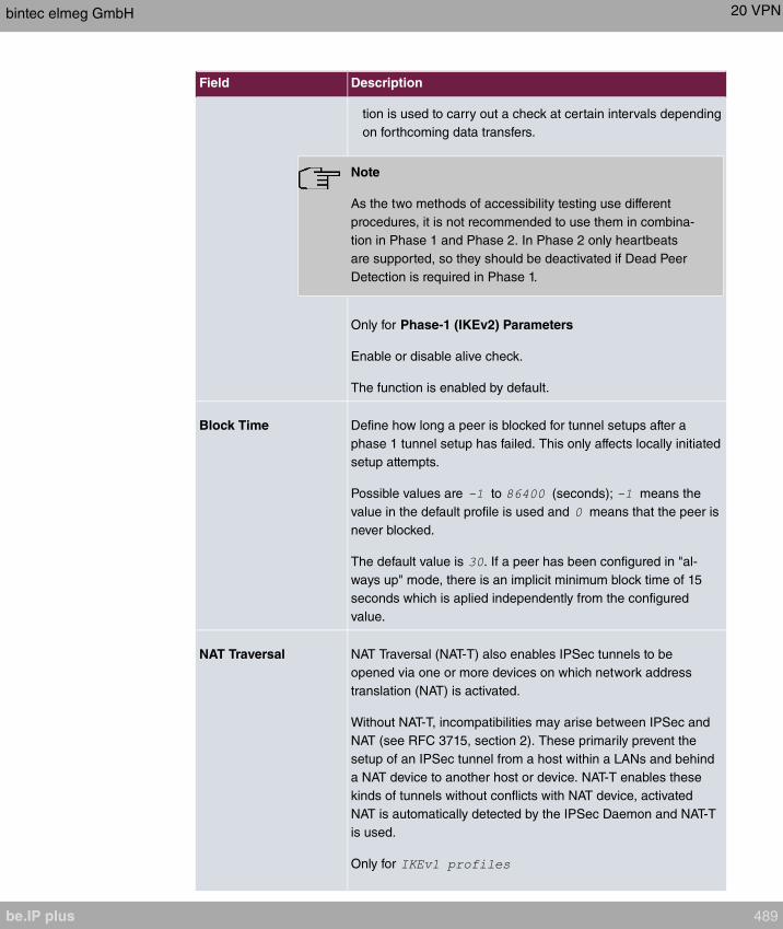
Field Description
tion is used to carry out a check at certain intervals depending
on forthcoming data transfers.
Note
As the two methods of accessibility testing use different
procedures, it is not recommended to use them in combina-
tion in Phase 1 and Phase 2. In Phase 2 only heartbeats
are supported, so they should be deactivated if Dead Peer
Detection is required in Phase 1.
Only for Phase-1 (IKEv2) Parameters
Enable or disable alive check.
The function is enabled by default.
Block Time Define how long a peer is blocked for tunnel setups after a
phase 1 tunnel setup has failed. This only affects locally initiated
setup attempts.
Possible values are to (seconds); means the
value in the default profile is used and means that the peer is
never blocked.
The default value is . If a peer has been configured in "al-
ways up" mode, there is an implicit minimum block time of 15
seconds which is aplied independently from the configured
value.
NAT Traversal NAT Traversal (NAT-T) also enables IPSec tunnels to be
opened via one or more devices on which network address
translation (NAT) is activated.
Without NAT-T, incompatibilities may arise between IPSec and
NAT (see RFC 3715, section 2). These primarily prevent the
setup of an IPSec tunnel from a host within a LANs and behind
a NAT device to another host or device. NAT-T enables these
kinds of tunnels without conflicts with NAT device, activated
NAT is automatically detected by the IPSec Daemon and NAT-T
is used.
Only for
bintec elmeg GmbH 20 VPN
be.IP plus 489

Field Description
Possible values:
• (default value): NAT Traversal is enabled.
• : NAT Traversal is disabled.
• : The device always behaves as it would if NAT were in
use.
Only for
The function is enabled with .
The function is enabled by default.
CA Certificates Only for Phase-1 (IKE) Parameters
Only for Authentication Method = ,
or
If you enable the Trust the following CA certificates option,
you can select up to three CA certificates that are accepted for
this profile.
This option can only be configured if certificates are loaded.
20.1.3 Phase-2 Profiles
You can define profiles for phase 2 of the tunnel setup just as for phase 1.
In the VPN->IPSec->Phase-2 Profiles menu, a list of all configured IPSec phase 2 profiles
is displayed.
In the Default column, you can mark the profile to be used as the default profile.
20.1.3.1 New
Choose the New button to create additional profiles.
The menu VPN->IPSec->Phase-2 Profiles->New consists of the following fields:
Fields in the Phase-2 (IPSEC) Parameters menu.
Field Description
Description Enter a description that uniquely identifies the profile.
20 VPN bintec elmeg GmbH
490 be.IP plus

Field Description
The maximum length of the entry is 255 characters.
Proposals In this field, you can select any combination of encryption and
message hash algorithms for IKE phase 2 on your default. The
combination of six encryption algorithms and two message hash
algorithms gives 12 possible values in this field.
Encryption algorithms (Encryption):
• : 3DES is an extension of the DES algorithm with an ef-
fective key length of 112 bits, which is rated as secure. It is
the slowest algorithm currently supported.
• : All options can be used.
• (default value): Rijndael has been nominated as AES
due to its fast key setup, low memory requirements, high level
of security against attacks and general speed. The partner's
AES key length is used here. If this has also selected the
parameter , a key length of 128 bits is used.
• : Rijndael has been nominated as AES due to its
fast key setup, low memory requirements, high level of secur-
ity against attacks and general speed. Here, it is used with a
key length of 128 bits.
• : Rijndael has been nominated as AES due to its
fast key setup, low memory requirements, high level of secur-
ity against attacks and general speed. Here, it is used with a
key length of 192 bits.
• : Rijndael has been nominated as AES due to its
fast key setup, low memory requirements, high level of secur-
ity against attacks and general speed. Here, it is used with a
key length of 256 bits.
• : Twofish was a final candidate for the AES
(Advanced Encryption Standard). It is rated as just as secure
as Rijndael (AES), but is slower.
• : Blowfish is a very secure and fast algorithm.
Twofish can be regarded as the successor to Blowfish.
• : CAST is also a very secure algorithm, marginally
slower than Blowfish, but faster than 3DES.
• : DES is an older encryption algorithm, which is rated as
weak due to its small effective length of 56 bits.
bintec elmeg GmbH 20 VPN
be.IP plus 491
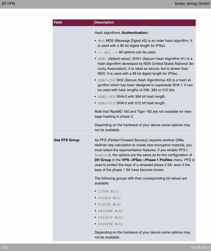
Field Description
Hash algorithms (Authentication):
• : MD5 (Message Digest #5) is an older hash algorithm. It
is used with a 96 bit digest length for IPSec.
• : All options can be used.
• (default value): SHA1 (Secure Hash Algorithm #1) is a
hash algorithm developed by NSA (United States National Se-
curity Association). It is rated as secure, but is slower than
MD5. It is used with a 96 bit digest length for IPSec.
• : SH2 (Secure Hash Algorithmus #2) is a hash al-
gorithm which has been designed to supersede SHA 1. It can
be used with hash lengths of 256, 384 or 512 bits.
• : SHA-2 with 384 bit hash length.
• : SHA-2 with 512 bit hash length.
Note that RipeMD 160 and Tiger 192 are not available for mes-
sage hashing in phase 2.
Depending on the hardware of your device some options may
not be available.
Use PFS Group As PFS (Perfect Forward Secrecy) requires another Diffie-
Hellman key calculation to create new encryption material, you
must select the exponentiation features. If you enable PFS (
), the options are the same as for the configuration of
DH Group in the VPN->IPSec->Phase-1 Profiles menu. PFS is
used to protect the keys of a renewed phase 2 SA, even if the
keys of the phase 1 SA have become known.
The following groups with their corresponding bit values are
available:
•
•
•
•
•
•
Depending on the hardware of your device some options may
not be available.
20 VPN bintec elmeg GmbH
492 be.IP plus
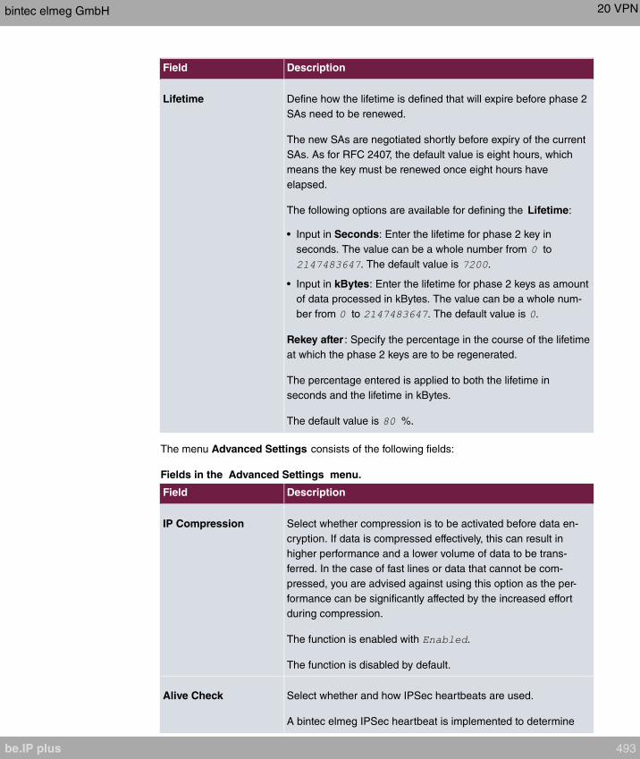
Field Description
Lifetime Define how the lifetime is defined that will expire before phase 2
SAs need to be renewed.
The new SAs are negotiated shortly before expiry of the current
SAs. As for RFC 2407, the default value is eight hours, which
means the key must be renewed once eight hours have
elapsed.
The following options are available for defining the Lifetime:
• Input in Seconds: Enter the lifetime for phase 2 key in
seconds. The value can be a whole number from to
. The default value is .
• Input in kBytes: Enter the lifetime for phase 2 keys as amount
of data processed in kBytes. The value can be a whole num-
ber from to . The default value is .
Rekey after : Specify the percentage in the course of the lifetime
at which the phase 2 keys are to be regenerated.
The percentage entered is applied to both the lifetime in
seconds and the lifetime in kBytes.
The default value is %.
The menu Advanced Settings consists of the following fields:
Fields in the Advanced Settings menu.
Field Description
IP Compression Select whether compression is to be activated before data en-
cryption. If data is compressed effectively, this can result in
higher performance and a lower volume of data to be trans-
ferred. In the case of fast lines or data that cannot be com-
pressed, you are advised against using this option as the per-
formance can be significantly affected by the increased effort
during compression.
The function is enabled with .
The function is disabled by default.
Alive Check Select whether and how IPSec heartbeats are used.
A bintec elmeg IPSec heartbeat is implemented to determine
bintec elmeg GmbH 20 VPN
be.IP plus 493

Field Description
whether or not a Security Association (SA) is still valid. This
function sends and receives signals every 5 seconds, depend-
ing on the configuration. If these signals are not received after
20 seconds, the SA is discarded as invalid.
Possible values:
• (default value): Automatic detection of whether
the remote terminal is a bintec elmeg device. If it is,
(for a remote terminal with bintec
elmeg) or (for a remote terminal without bintec el-
meg) is set.
• : Your device sends and expects no heartbeat. Set
this option if you use devices from other manufacturers.
• : Your device expects a
heartbeat from the peer but does not send one itself.
• : Your device expects no heart-
beat from the peer, but sends one itself.
• : Your device expects a
heartbeat from the peer and sends one itself.
Note
In Phase 1 and Phase 2, your device supports different
methods of accessibility testing: In Phase 1, dead peer de-
tection and heartbeats, in Phase 2 only heartbeats. Since
the two methods of accessibility testing use different pro-
cedures, it is not recommended to combine them in Phase
1 and Phase 2. Heartbeats should therefore be deactivated
in Phase 2 if Dead Peer Detection is required in Phase 1.
Propagate PMTU Select whether the PMTU (Path Maximum Transfer Unit) is to
be propagated during phase 2.
The function is enabled with .
The function is enabled by default.
20 VPN bintec elmeg GmbH
494 be.IP plus
20.1.4 XAUTH Profiles
In the XAUTH Profiles menu a list of all XAUTH profiles is displayed.
Extended Authentication for IPSec (XAuth) is an additional authentication method for IPSec
tunnel users.
The gateway can take on two different roles when using XAuth as it can act as a server or
as a client:
• As a server the gateway requires a proof of authorisation.
• As a client the gateway provides proof of authorisation.
In server mode, multiple users can obtain authentication via XAuth, e.g. users of Apple
iPhones. Multiple users can dial-in either one after another or simultaneously via a so-
called multi peer. Authorisation is verified either on the basis of a list or via a Radius Serv-
er. If using a one time password (OTP), the password check can be carried out by a token
server (e.g. SecOVID from Kobil), which is installed behind the Radius Server.
If a company's headquarters is connected to several branches via IPSec, several peers can
be configured, for example, one peer for each branch. A password is assigned to each
peer, i.e. each branch. Besides this authentication method per branch, XAuth offers an ad-
ditional method for logging in individually and independently from a user's location via a
private password. A specific user can then use the IPSec tunnel across various peers. This
is useful, for example, if an employee works alternately in different branches and if he
needs to have individual access to the tunnel.
All users are assigned the same password in a so-called multi peer, i.e. a group password.
Here, XAuth offers an individual authentication method to the user, too. If in a branch, for
example, multiple users have access to a tunnel via a multi peer, it may have an adventage
for users with different tasks that each of them uses a private password.
XAuth is carried out once IPSec IKE (Phase 1) has been completed successfully and be-
fore IKE (Phase 2) begins.
If XAuth is used together with IKE Config Mode, the transactions for XAuth are carried out
before the transactions for IKE Config Mode.
20.1.4.1 New
Choose the New button to create additional profiles.
The VPN->IPSec->XAUTH Profiles ->New menu consists of the following fields:
Fields in the Basic Parameters menu.
bintec elmeg GmbH 20 VPN
be.IP plus 495
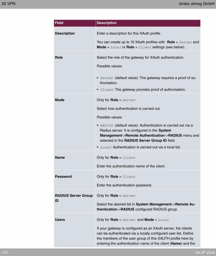
Field Description
Description Enter a description for this XAuth profile.
You can create up to 10 XAuth profiles with Role = and
Mode = or Role = settings (see below).
Role Select the role of the gateway for XAuth authentication.
Possible values:
• (default value): The gateway requires a proof of au-
thorisation.
• : The gateway provides proof of authorisation.
Mode Only for Role =
Select how authentication is carried out.
Possible values:
• (default value): Authentication is carried out via a
Radius server. It is configured in the System
Management->Remote Authentication->RADIUS menu and
selected in the RADIUS Server Group ID field.
• : Authentication is carried out via a local list.
Name Only for Role =
Enter the authentication name of the client.
Password Only for Role =
Enter the authentication password.
RADIUS Server Group
ID
Only for Role =
Select the desired list in System Management->Remote Au-
thentication->RADIUS configured RADIUS group.
Users Only for Role = and Mode =
If your gateway is configured as an XAuth server, the clients
can be authenticated via a locally configured user list. Define
the members of the user group of this XAUTH profile here by
entering the authentication name of the client (Name) and the
20 VPN bintec elmeg GmbH
496 be.IP plus
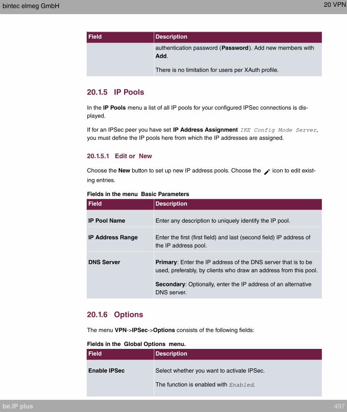
Field Description
authentication password (Password). Add new members with
Add.
There is no limitation for users per XAuth profile.
20.1.5 IP Pools
In the IP Pools menu a list of all IP pools for your configured IPSec connections is dis-
played.
If for an IPSec peer you have set IP Address Assignment ,
you must define the IP pools here from which the IP addresses are assigned.
20.1.5.1 Edit or New
Choose the New button to set up new IP address pools. Choose the icon to edit exist-
ing entries.
Fields in the menu Basic Parameters
Field Description
IP Pool Name Enter any description to uniquely identify the IP pool.
IP Address Range Enter the first (first field) and last (second field) IP address of
the IP address pool.
DNS Server Primary: Enter the IP address of the DNS server that is to be
used, preferably, by clients who draw an address from this pool.
Secondary: Optionally, enter the IP address of an alternative
DNS server.
20.1.6 Options
The menu VPN->IPSec->Options consists of the following fields:
Fields in the Global Options menu.
Field Description
Enable IPSec Select whether you want to activate IPSec.
The function is enabled with .
bintec elmeg GmbH 20 VPN
be.IP plus 497
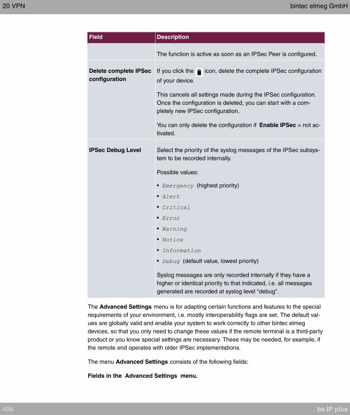
Field Description
The function is active as soon as an IPSec Peer is configured.
Delete complete IPSec
configuration
If you click the icon, delete the complete IPSec configuration
of your device.
This cancels all settings made during the IPSec configuration.
Once the configuration is deleted, you can start with a com-
pletely new IPSec configuration.
You can only delete the configuration if Enable IPSec = not ac-
tivated.
IPSec Debug Level Select the priority of the syslog messages of the IPSec subsys-
tem to be recorded internally.
Possible values:
• (highest priority)
•
•
•
•
•
•
• (default value, lowest priority)
Syslog messages are only recorded internally if they have a
higher or identical priority to that indicated, i.e. all messages
generated are recorded at syslog level "debug".
The Advanced Settings menu is for adapting certain functions and features to the special
requirements of your environment, i.e. mostly interoperability flags are set. The default val-
ues are globally valid and enable your system to work correctly to other bintec elmeg
devices, so that you only need to change these values if the remote terminal is a third-party
product or you know special settings are necessary. These may be needed, for example, if
the remote end operates with older IPSec implementations.
The menu Advanced Settings consists of the following fields:
Fields in the Advanced Settings menu.
20 VPN bintec elmeg GmbH
498 be.IP plus
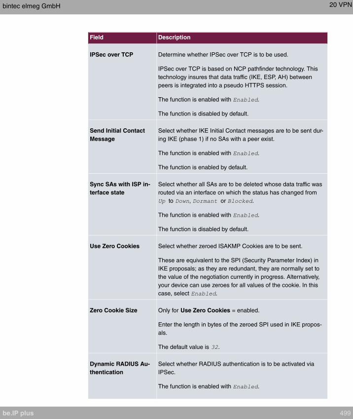
Field Description
IPSec over TCP Determine whether IPSec over TCP is to be used.
IPSec over TCP is based on NCP pathfinder technology. This
technology insures that data traffic (IKE, ESP, AH) between
peers is integrated into a pseudo HTTPS session.
The function is enabled with .
The function is disabled by default.
Send Initial Contact
Message
Select whether IKE Initial Contact messages are to be sent dur-
ing IKE (phase 1) if no SAs with a peer exist.
The function is enabled with .
The function is enabled by default.
Sync SAs with ISP in-
terface state
Select whether all SAs are to be deleted whose data traffic was
routed via an interface on which the status has changed from
to , or .
The function is enabled with .
The function is disabled by default.
Use Zero Cookies Select whether zeroed ISAKMP Cookies are to be sent.
These are equivalent to the SPI (Security Parameter Index) in
IKE proposals; as they are redundant, they are normally set to
the value of the negotiation currently in progress. Alternatively,
your device can use zeroes for all values of the cookie. In this
case, select .
Zero Cookie Size Only for Use Zero Cookies = enabled.
Enter the length in bytes of the zeroed SPI used in IKE propos-
als.
The default value is .
Dynamic RADIUS Au-
thentication
Select whether RADIUS authentication is to be activated via
IPSec.
The function is enabled with .
bintec elmeg GmbH 20 VPN
be.IP plus 499
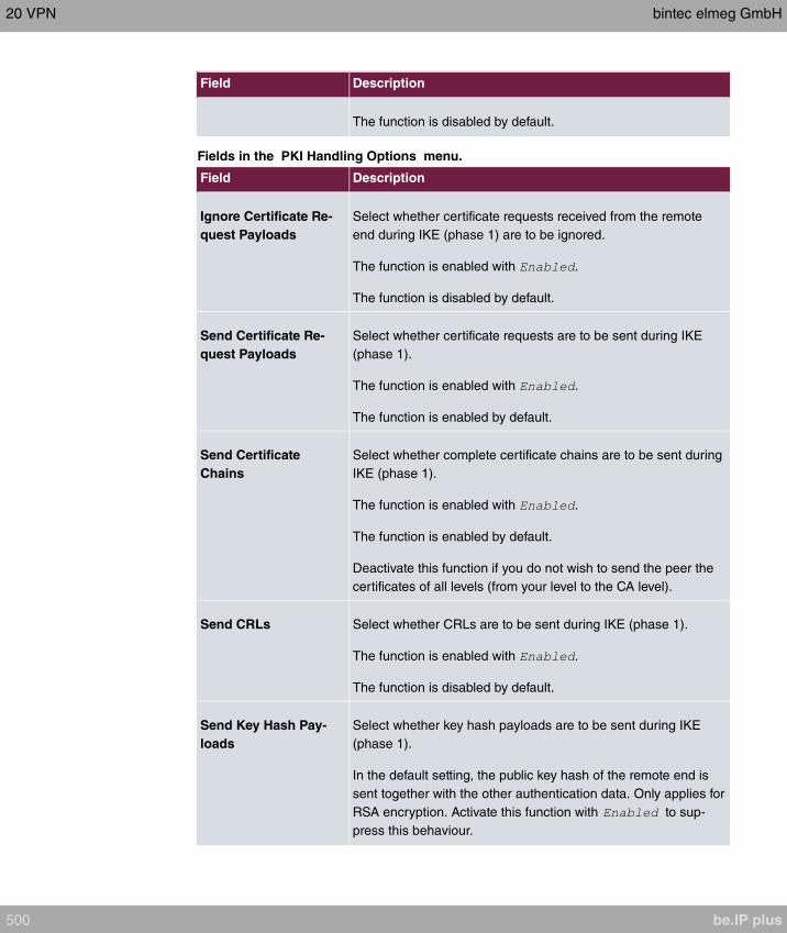
Field Description
The function is disabled by default.
Fields in the PKI Handling Options menu.
Field Description
Ignore Certificate Re-
quest Payloads
Select whether certificate requests received from the remote
end during IKE (phase 1) are to be ignored.
The function is enabled with .
The function is disabled by default.
Send Certificate Re-
quest Payloads
Select whether certificate requests are to be sent during IKE
(phase 1).
The function is enabled with .
The function is enabled by default.
Send Certificate
Chains
Select whether complete certificate chains are to be sent during
IKE (phase 1).
The function is enabled with .
The function is enabled by default.
Deactivate this function if you do not wish to send the peer the
certificates of all levels (from your level to the CA level).
Send CRLs Select whether CRLs are to be sent during IKE (phase 1).
The function is enabled with .
The function is disabled by default.
Send Key Hash Pay-
loads
Select whether key hash payloads are to be sent during IKE
(phase 1).
In the default setting, the public key hash of the remote end is
sent together with the other authentication data. Only applies for
RSA encryption. Activate this function with to sup-
press this behaviour.
20 VPN bintec elmeg GmbH
500 be.IP plus
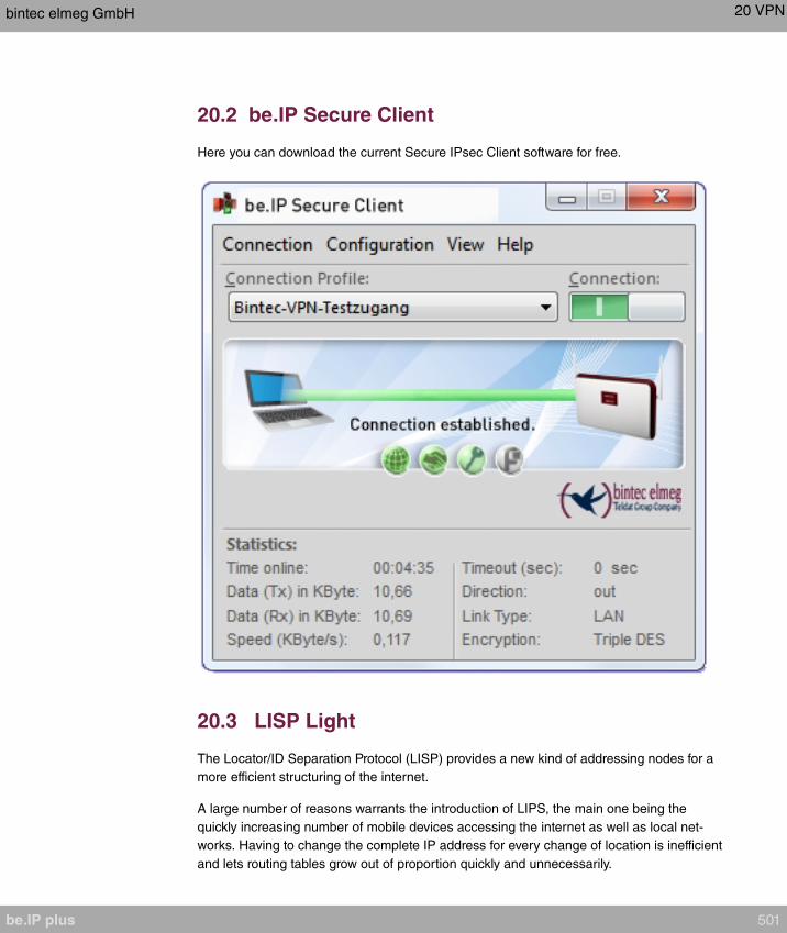
20.2 be.IP Secure Client
Here you can download the current Secure IPsec Client software for free.
20.3 LISP Light
The Locator/ID Separation Protocol (LISP) provides a new kind of addressing nodes for a
more efficient structuring of the internet.
A large number of reasons warrants the introduction of LIPS, the main one being the
quickly increasing number of mobile devices accessing the internet as well as local net-
works. Having to change the complete IP address for every change of location is inefficient
and lets routing tables grow out of proportion quickly and unnecessarily.
bintec elmeg GmbH 20 VPN
be.IP plus 501
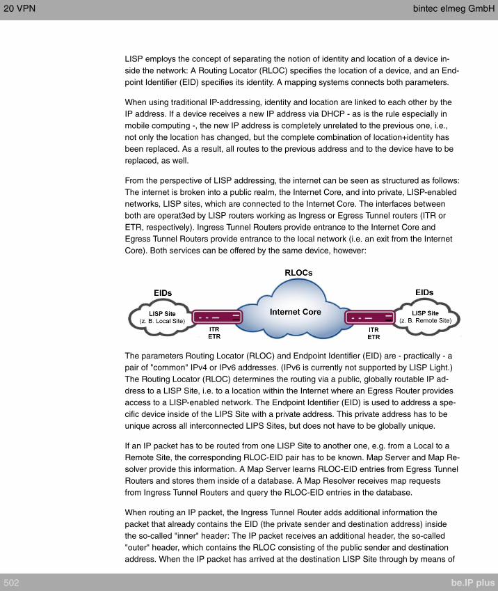
LISP employs the concept of separating the notion of identity and location of a device in-
side the network: A Routing Locator (RLOC) specifies the location of a device, and an End-
point Identifier (EID) specifies its identity. A mapping systems connects both parameters.
When using traditional IP-addressing, identity and location are linked to each other by the
IP address. If a device receives a new IP address via DHCP - as is the rule especially in
mobile computing -, the new IP address is completely unrelated to the previous one, i.e.,
not only the location has changed, but the complete combination of location+identity has
been replaced. As a result, all routes to the previous address and to the device have to be
replaced, as well.
From the perspective of LISP addressing, the internet can be seen as structured as follows:
The internet is broken into a public realm, the Internet Core, and into private, LISP-enabled
networks, LISP sites, which are connected to the Internet Core. The interfaces between
both are operat3ed by LISP routers working as Ingress or Egress Tunnel routers (ITR or
ETR, respectively). Ingress Tunnel Routers provide entrance to the Internet Core and
Egress Tunnel Routers provide entrance to the local network (i.e. an exit from the Internet
Core). Both services can be offered by the same device, however:
The parameters Routing Locator (RLOC) and Endpoint Identifier (EID) are - practically - a
pair of "common" IPv4 or IPv6 addresses. (IPv6 is currently not supported by LISP Light.)
The Routing Locator (RLOC) determines the routing via a public, globally routable IP ad-
dress to a LISP Site, i.e. to a location within the Internet where an Egress Router provides
access to a LISP-enabled network. The Endpoint Identifier (EID) is used to address a spe-
cific device inside of the LIPS Site with a private address. This private address has to be
unique across all interconnected LIPS Sites, but does not have to be globally unique.
If an IP packet has to be routed from one LISP Site to another one, e.g. from a Local to a
Remote Site, the corresponding RLOC-EID pair has to be known. Map Server and Map Re-
solver provide this information. A Map Server learns RLOC-EID entries from Egress Tunnel
Routers and stores them inside of a database. A Map Resolver receives map requests
from Ingress Tunnel Routers and query the RLOC-EID entries in the database.
When routing an IP packet, the Ingress Tunnel Router adds additional information the
packet that already contains the EID (the private sender and destination address) inside
the so-called "inner" header: The IP packet receives an additional header, the so-called
"outer" header, which contains the RLOC consisting of the public sender and destination
address. When the IP packet has arrived at the destination LISP Site through by means of
20 VPN bintec elmeg GmbH
502 be.IP plus

the RLOC, the Egress Tunnel Router unwraps it. Using the EID information the packet is
then transmitted to the final recipient.
LISP Light means that only a subset of the LISP specification from RFC 6830 has been
implemented in order to provide the core routing functions.
20.3.1 Router (ITR/ETR)
The menu VPN->LISP Light->Router (ITR/ETR) displays a list of all Egress Tunnel
Routers (ETR, top card) and of all Ingress Tunnel Routers (ITR, bottom card). Your device
operates as Egress Tunnel Router as well as as Ingress Tunnel Router.
20.3.1.1 Add Egress Tunnel Router
Here you carry out the configuration of the Egress Tunnel Router role. For a standard LISP
configuration you have to configure at least one Map Server.
The device propagates its own IP address to the Map Server(s) in order to signal that it can
receive data packets and via which RLOC it can be accessed as ETR.
An Egress Tunnel Router (ETR) propagates EID-RLOC entries for "its" LISP Sites and re-
ceives LISP data, unwraps them and sends them to the devices specidied in the EID.
The menu VPN->LISP Light->Router (ITR/ETR)->Add Egress Tunnel Router consists of
the following fields:
Fields in the menu Map Server
Field Description
Map Server IP Address Specify the IP address of the Map Server that is to receive the
Map Request messages.
Key type (HMAC Al-
gorithm)
Messages sent to the Map Server can be signed. Here you can
select the signing algorithm.
Possible values:
•
•
•
deactivates message signing.
Authentication key The Authentication key must also be known to the Map Server
in order for it to verify message authenticity.
bintec elmeg GmbH 20 VPN
be.IP plus 503
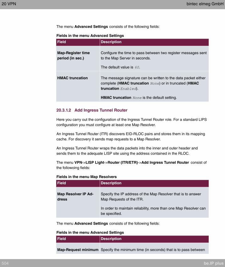
The menu Advanced Settings consists of the following fields:
Fields in the menu Advanced Settings
Field Description
Map-Register time
period (in sec.)
Configure the time to pass between two register messages sent
to the Map Server in seconds.
The default value is .
HMAC truncation The message signature can be written to the data packet either
complete (HMAC truncation ) or in truncated (HMAC
truncation ).
HMAC truncation is the default setting.
20.3.1.2 Add Ingress Tunnel Router
Here you carry out the configuration of the Ingress Tunnel Router role. For a standard LIPS
configuration you must configure at least one Map Resolver.
An Ingress Tunnel Router (ITR) discovers EID-RLOC pairs and stores them in its mapping
cache. For discovery it sends map requests to a Map Resolver.
An Ingress Tunnel Router wraps the data packets into the inner and outer header and
sends them to the adequate LISP site using the address contained in the RLOC.
The menu VPN->LISP Light->Router (ITR/ETR)->Add Ingress Tunnel Router consist of
the followoing fields:
Fields in the menu Map Resolvers
Field Description
Map Resolver IP Ad-
dress
Specify the IP address of the Map Resolver that is to answer
Map Requests of the ITR.
In order to maintain reliability, more than one Map Resolver can
be specified.
The menu Advanced Settings consists of the following fields:
Fields in the menu Advanced Settings
Field Description
Map-Request minimum Specify the minimum time (in seconds) that is to pass between
20 VPN bintec elmeg GmbH
504 be.IP plus
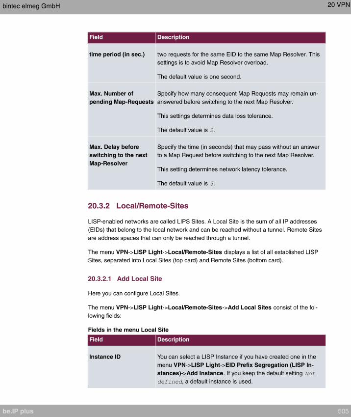
Field Description
time period (in sec.) two requests for the same EID to the same Map Resolver. This
settings is to avoid Map Resolver overload.
The default value is one second.
Max. Number of
pending Map-Requests
Specify how many consequent Map Requests may remain un-
answered before switching to the next Map Resolver.
This settings determines data loss tolerance.
The default value is .
Max. Delay before
switching to the next
Map-Resolver
Specify the time (in seconds) that may pass without an answer
to a Map Request before switching to the next Map Resolver.
This setting determines network latency tolerance.
The default value is .
20.3.2 Local/Remote-Sites
LISP-enabled networks are called LIPS Sites. A Local Site is the sum of all IP addresses
(EIDs) that belong to the local network and can be reached without a tunnel. Remote Sites
are address spaces that can only be reached through a tunnel.
The menu VPN->LISP Light->Local/Remote-Sites displays a list of all established LISP
Sites, separated into Local Sites (top card) and Remote Sites (bottom card).
20.3.2.1 Add Local Site
Here you can configure Local Sites.
The menu VPN->LISP Light->Local/Remote-Sites->Add Local Sites consist of the fol-
lowing fields:
Fields in the menu Local Site
Field Description
Instance ID You can select a LISP Instance if you have created one in the
menu VPN->LISP Light->EID Prefix Segregation (LISP In-
stances)->Add Instance. If you keep the default setting
, a default instance is used.
bintec elmeg GmbH 20 VPN
be.IP plus 505

Field Description
EID prefix (IP address)
/ Length
Specify the IP prefix of the Endpoint Identifier (EID). Use a LAN
address from your network.
Route Locator (RLOC)
IP address
In order for the remote tunnel router to know at which IP ad-
dress your device can be reached, a globally routable IP ad-
dress (RLOC of the ETR role) is automatically determined and
displayed.
The menu Advanced Settings consists of the following fields:
Fields in the menu Advanced Settings
Field Description
Interface binding Selecting and interface is optional. If the same EID is used for
multiple interface, one of the interfaces can be assigned here.
Database Record TTL
(in min.)
Designates the cache entry life time (in minutes) reported to the
Map Server.
The default value is minutes.
Exclude EID prefix
from tree
If you intend to use a continuous address range, keep the de-
fault setting .
You can remove a sub range from an already created address
range. For this, create individual entries with the set-
ting.
20.3.2.2 Add Remote Site
Here you can configure Remote Sites.
The menu VPN->LISP Light->Local/Remote-Sites->Add Remote Site consists of the fol-
lowing fields:
Fields in the menu Remote Site
Field Description
ID You can select a LISP Instance if you have created one in the
menu VPN->LISP Light->EID Prefix Segregation (LISP In-
stances)->Add Instance. If you keep the default setting
, a default instance is used.
20 VPN bintec elmeg GmbH
506 be.IP plus
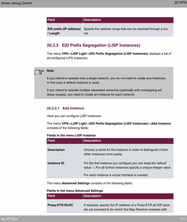
Field Description
EID prefix (IP address)
/ Length
Specify the address range that can be reached through a tun-
nel.
20.3.3 EID Prefix Segregation (LISP Instances)
The menu VPN->LISP Light->EID Prefix Segregation (LISP Instances) displays a list of
all configured LIPS Instances.
Note
If you intend to operate only a single network, you do not need to create any instances.
In this case a default instance is used.
If you intend to operate multiple separated networks (optionally with overlapping ad-
dress ranges), you need to create an instance for each network.
20.3.3.1 Add Instance
Here you can configure LISP Instances.
The menu VPN->LISP Light->EID Prefix Segregation (LISP Instances)->Add Instance
consists of the following fields:
Fields in the menu LISP Instance
Field Description
Description Choose a name for the instance in order to distinguish it from
other instances more easily.
Instance ID For the first instance you configure you can keep the default
value . For all further instances specify a unique integer value.
For each instance a virtual interface is created.
The menu Advanced Settings consists of the following fields:
Fields in the menu Advanced Settings
Field Description
Proxy-ETR-RLOC If required, specify the IP address of a Proxy-ETR all IOP pack-
ets are tunneled to for which the Map Resolver answers with
bintec elmeg GmbH 20 VPN
be.IP plus 507

Field Description
"forward-native".
LISP interface MTU Specify the maximun packet size (Maximum Transfer Unit,
MTU) in bytes that can be used for the connection between the
virtual LISP interfaces.
The default value is .
Maximum number of
cached EID/RLOC
entries per ins
Specify the maximum number of EID/RLOC entries in the
cache.
The default value .
Maximum number of
RLOC addresses per
cached EID
Specify the maximum number of RLOC entries in the cache.
The default value is .
Default TTL of cached
EID/RLOC entry (in
minutes)
Normally, the server provides a value for the TTL (time to live).
Here you can specify a value for the case that the server does
not provide one (Default TTL Mode = ) or the server-
provided value is to be ignored (Default TTL Mode = ).
Default TTL Mode Here you can select the fefaulöt TTL mode.
Possible values:
• (default value): The server does not provide a
TTL value. The value specified for Default TTL of cached
EID/RLOC entry (in minutes) is used.
• : The value provided by the server is ignored. the value
specified for Default TTL of cached EID/RLOC entry (in
minutes) is used.
20.4 L2TP
The layer 2 tunnel protocol (L2TP) enables PPP connections to be tunnelled via a UDP
connection.
Your bintec elmeg device supports the following two modes:
• L2TP LNS Mode (L2TP Network Server): for incoming connections only
• L2TP LAC Mode (L2TP Access Concentrator): for outgoing connections only
20 VPN bintec elmeg GmbH
508 be.IP plus

Note the following when configuring the server and client: An L2TP tunnel profile must be
created on each of the two sides (LAC and LNS). The corresponding L2TP tunnel profile is
used on the initiator side (LAC) to set up the connection. The L2TP tunnel profile is needed
on the responder side (LNS) to accept the connection.
20.4.1 Tunnel Profiles
A list of all configured tunnel profiles is displayed in the VPN->L2TP->Tunnel Profiles
menu.
20.4.1.1 New
Choose the New button to create additional tunnel profiles.
The menu VPN->L2TP->Tunnel Profiles ->New consists of the following fields:
Fields in the Basic Parameters menu.
Field Description
Description Enter a description for the current profile.
The device automatically names the profiles
and numbers them, but the value can be changed.
Local HostnameEnter the host name for LNS or LAC.
• : The local hostname is used in outgoing tunnel setup
messages to identify this device and is associated with the re-
mote hostname of a tunnel profile configured on the LNS.
These tunnel setup messages are SCCRQs (Start Control
Connection Request) sent from the LAC and SCCRPs (Start
Control Connection Reply) sent from the LNS.
• : Is the same as the value for Remote Hostname of the
incoming tunnel setup message from the LAC.
Remote HostnameEnter the host name of the LNS or LAC.
• : Defines the value for Local Hostname of the LNS
(contained in the SCCRQs received from the LNS and the
SCCRPs received from the LAC). A Local Hostname con-
figured in the LAC must match Remote Hostname configured
for the intended profile in the LNS and vice versa.
• : Defines the Local Hostname of the LAC. If the Remote
Hostname field remains empty on the LNS, the related profile
qualifies as the standard entry and is used for all incoming
bintec elmeg GmbH 20 VPN
be.IP plus 509

Field Description
calls for which a profile with a matching remote hostname
cannot be found.
Password Enter the password to be used for tunnel authentication. Au-
thentication between LAC and LNS takes place in both direc-
tions, i.e. the LNS checks the Local Hostname and the Pass-
wordcontained in the SCCRQ of the LAC and compares them
with those specified in the relevant profile. The LAC does the
same with the fields of the SCCRP of the LNS.
If this field remains empty, authentication data in the tunnel
setup messages are not sent and are ignored.
Fields in the LAC Mode Parameters menu.
Field Description
Remote IP Address Enter the fixed IP address of the LNS used as the destination
address for connections based on this profile.
The destination must be a device that can behave like an LNS.
UDP Source Port Enter how the port number to be used as the source port for all
outgoing L2TP connections based on this profile is to be de-
termined.
By default, the Fixed option is disabled, which means that ports
are dynamically assigned to the connections that use this pro-
file.
If you want to enter a fixed port, enable the option. Se-
lect this option if you encounter problems with the firewall or
NAT.
The available values are to .
UDP Destination Port Enter the destination port number to be used for all calls based
on this profile. The remote LNS that receives the call must mon-
itor this port on L2TP connections.
Possible values are to .
The default value is (RFC 2661).
The menu Advanced Settings consists of the following fields:
20 VPN bintec elmeg GmbH
510 be.IP plus
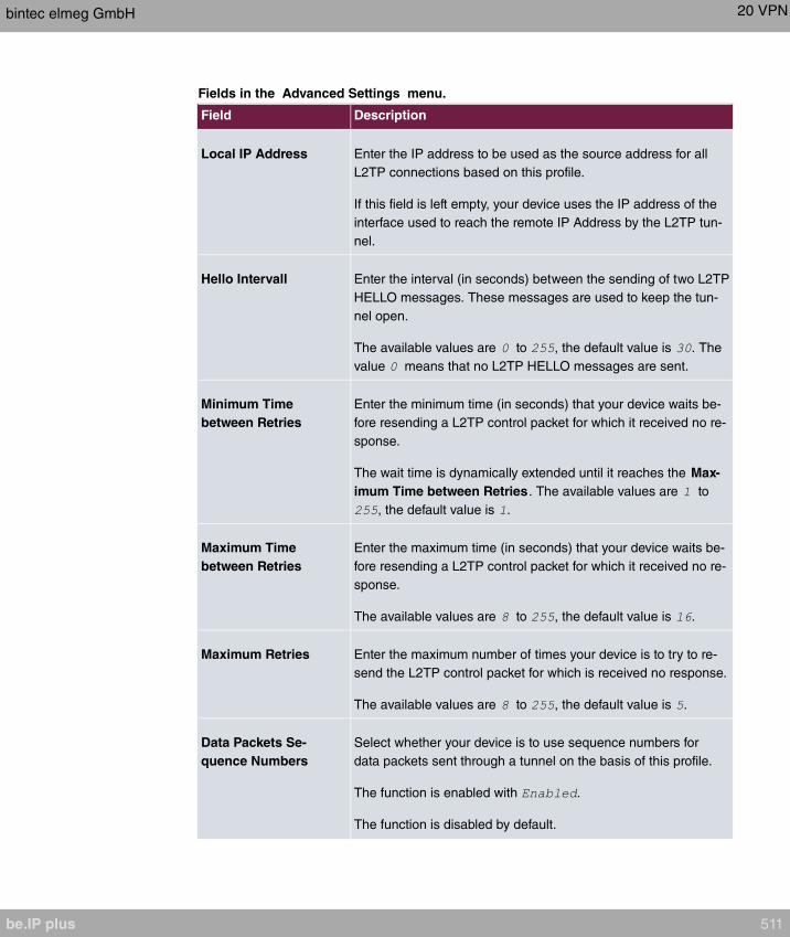
Fields in the Advanced Settings menu.
Field Description
Local IP Address Enter the IP address to be used as the source address for all
L2TP connections based on this profile.
If this field is left empty, your device uses the IP address of the
interface used to reach the remote IP Address by the L2TP tun-
nel.
Hello Intervall Enter the interval (in seconds) between the sending of two L2TP
HELLO messages. These messages are used to keep the tun-
nel open.
The available values are to , the default value is . The
value means that no L2TP HELLO messages are sent.
Minimum Time
between Retries
Enter the minimum time (in seconds) that your device waits be-
fore resending a L2TP control packet for which it received no re-
sponse.
The wait time is dynamically extended until it reaches the Max-
imum Time between Retries. The available values are to
, the default value is .
Maximum Time
between Retries
Enter the maximum time (in seconds) that your device waits be-
fore resending a L2TP control packet for which it received no re-
sponse.
The available values are to , the default value is .
Maximum Retries Enter the maximum number of times your device is to try to re-
send the L2TP control packet for which is received no response.
The available values are to , the default value is .
Data Packets Se-
quence Numbers
Select whether your device is to use sequence numbers for
data packets sent through a tunnel on the basis of this profile.
The function is enabled with .
The function is disabled by default.
bintec elmeg GmbH 20 VPN
be.IP plus 511
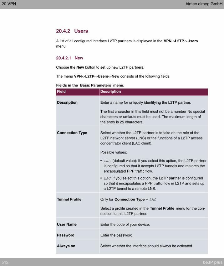
20.4.2 Users
A list of all configured interface L2TP partners is displayed in the VPN->L2TP->Users
menu.
20.4.2.1 New
Choose the New button to set up new L2TP partners.
The menu VPN->L2TP->Users->New consists of the following fields:
Fields in the Basic Parameters menu.
Field Description
Description Enter a name for uniquely identifying the L2TP partner.
The first character in this field must not be a number No special
characters or umlauts must be used. The maximum length of
the entry is 25 characters.
Connection Type Select whether the L2TP partner is to take on the role of the
L2TP network server (LNS) or the functions of a L2TP access
concentrator client (LAC client).
Possible values:
• (default value): If you select this option, the L2TP partner
is configured so that it accepts L2TP tunnels and restores the
encapsulated PPP traffic flow.
• : If you select this option, the L2TP partner is configured
so that it encapsulates a PPP traffic flow in L2TP and sets up
a L2TP tunnel to a remote LNS.
Tunnel Profile Only for Connection Type =
Select a profile created in the Tunnel Profile menu for the con-
nection to this L2TP partner.
User Name Enter the code of your device.
Password Enter the password.
Always on Select whether the interface should always be activated.
20 VPN bintec elmeg GmbH
512 be.IP plus
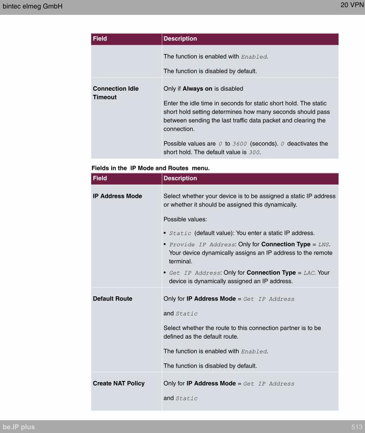
Field Description
The function is enabled with .
The function is disabled by default.
Connection Idle
Timeout
Only if Always on is disabled
Enter the idle time in seconds for static short hold. The static
short hold setting determines how many seconds should pass
between sending the last traffic data packet and clearing the
connection.
Possible values are to (seconds). deactivates the
short hold. The default value is .
Fields in the IP Mode and Routes menu.
Field Description
IP Address Mode Select whether your device is to be assigned a static IP address
or whether it should be assigned this dynamically.
Possible values:
• (default value): You enter a static IP address.
• : Only for Connection Type = .
Your device dynamically assigns an IP address to the remote
terminal.
• : Only for Connection Type = . Your
device is dynamically assigned an IP address.
Default Route Only for IP Address Mode =
and
Select whether the route to this connection partner is to be
defined as the default route.
The function is enabled with .
The function is disabled by default.
Create NAT Policy Only for IP Address Mode =
and
bintec elmeg GmbH 20 VPN
be.IP plus 513
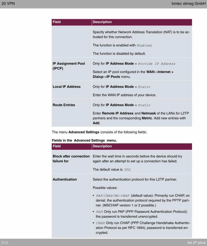
Field Description
Specify whether Network Address Translation (NAT) is to be ac-
tivated for this connection.
The function is enabled with .
The function is disabled by default.
IP Assignment Pool
(IPCP)
Only for IP Address Mode =
Select an IP pool configured in the WAN->Internet +
Dialup->IP Pools menu.
Local IP Address Only for IP Address Mode =
Enter the WAN IP address of your device.
Route Entries Only for IP Address Mode =
Enter Remote IP Address and Netmask of the LANs for L2TP
partners and the corresponding Metric. Add new entries with
Add.
The menu Advanced Settings consists of the following fields:
Fields in the Advanced Settings menu.
Field Description
Block after connection
failure for
Enter the wait time in seconds before the device should try
again after an attempt to set up a connection has failed.
The default value is .
Authentication Select the authentication protocol for this L2TP partner.
Possible values:
• (default value): Primarily run CHAP, on
denial, the authentication protocol required by the PPTP part-
ner. (MSCHAP version 1 or 2 possible.)
• : Only run PAP (PPP Password Authentication Protocol);
the password is transferred unencrypted.
• : Only run CHAP (PPP Challenge Handshake Authentic-
ation Protocol as per RFC 1994); password is transferred en-
crypted.
20 VPN bintec elmeg GmbH
514 be.IP plus

Field Description
• : Primarily run CHAP, otherwise PAP.
• : Only run MS-CHAP version 1 (PPP Microsoft
Challenge Handshake Authentication Protocol).
• : Run MS-CHAP version 2 only.
• : Some providers use no authentication. In this case, se-
lect this option.
Encryption If necessary, select the type of encryption that should be used
for data traffic to the L2TP partner. This is only possible if STAC
or MS-STAC compression is not activated for the connection. If
Encryption is set, the remote terminal must also support it, oth-
erwise a connection cannot be set up.
Possible values:
• : MPP encryption is not used.
• (default value): MPP encryption V2 with 128 bit is
used to RFC 3078.
• : MPP encryption V2 with 128 bit is
used as compatible with Microsoft and Cisco.
LCP Alive Check Select whether the availability of the remote terminal is to be
checked by sending LCP echo requests or replies. This is re-
commended for leased lines, PPTP and L2TP connections.
The function is enabled with .
The function is enabled by default.
Prioritize TCP ACK
Packets
Select whether the TCP download is to be optimised in the
event of intensive TCP upload. This function can be specially
applied for asymmetrical bandwidths (ADSL).
The function is enabled with .
The function is disabled by default.
Fields in the IP Options menu.
Field Description
OSPF Mode Select whether and how routes are propagated via the interface
and/or OSPF protocol packets are sent.
bintec elmeg GmbH 20 VPN
be.IP plus 515
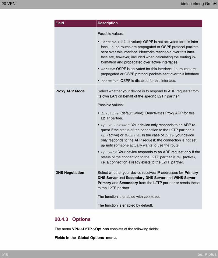
Field Description
Possible values:
• (default value): OSPF is not activated for this inter-
face, i.e. no routes are propagated or OSPF protocol packets
sent over this interface. Networks reachable over this inter-
face are, however, included when calculating the routing in-
formation and propagated over active interfaces.
• : OSPF is activated for this interface, i.e. routes are
propagated or OSPF protocol packets sent over this interface.
• : OSPF is disabled for this interface.
Proxy ARP Mode Select whether your device is to respond to ARP requests from
its own LAN on behalf of the specific L2TP partner.
Possible values:
• (default value): Deactivates Proxy ARP for this
L2TP partner.
• : Your device only responds to an ARP re-
quest if the status of the connection to the L2TP partner is
(active) or . In the case of , your device
only responds to the ARP request; the connection is not set
up until someone actually wants to use the route.
• : Your device responds to an ARP request only if the
status of the connection to the L2TP partner is (active),
i.e. a connection already exists to the L2TP partner.
DNS Negotiation Select whether your device receives IP addresses for Primary
DNS Server und Secondary DNS Server and WINS Server
Primary and Secondary from the L2TP partner or sends these
to the L2TP partner.
The function is enabled with .
The function is enabled by default.
20.4.3 Options
The menu VPN->L2TP->Options consists of the following fields:
Fields in the Global Options menu.
20 VPN bintec elmeg GmbH
516 be.IP plus

Field Description
UDP Destination Port Enter the port to be monitored by the LNS on incoming L2TP
tunnel connections.
Available values are all whole numbers from to , the
default value is , as specified in RFC 2661.
UDP Source Port Se-
lection
Select whether the LNS should only use the monitored port
(UDP Destination Port) as the local source port for the L2TP
connection.
The function is enabled with .
The function is disabled by default.
bintec elmeg GmbH 20 VPN
be.IP plus 517
Chapter 21 Firewall
The Stateful Inspection Firewall (SIF) provided for bintec elmeg gateways is a powerful se-
curity feature.
The SIF with dynamic packet filtering has a decisive advantage over static packet filtering:
The decision whether or not to send a packet cannot be made solely on the basis of source
and destination addresses or ports but also using dynamic packet filtering based on the
state of the connection to a partner.
This means packets that belong to an already active connection can also be forwarded.
The SIF also accepts packets that belong to an "affiliated connection". The negotiation of
an FTP connection takes place over port 21, for example, but the actual data exchange can
take place over a completely different port.
SIF and other security features
The Stateful Inspection Firewall fits into the existing security architecture of bintec elmeg.
The configuration work for the SIF is comparatively straightforward with systems like Net-
work Address Translation (NAT) and IP Access Lists (IPAL).
As SIF, NAT and IPAL are active in the system simultaneously, attention must be given to
possible interaction: If any packet is rejected by one of the security instances, this is done
immediately. This is irrelevant whether another instance would accept it or not. Your need
for security features should therefore be accurately analysed.
The essential difference between SIF and NAT/IPAL is that the rules for the SIF are gener-
ally applied globally, i.e. not restricted to one interface.
In principle, the same filter criteria are applied to the data traffic as those used in NAT and
IPAL:
• Source and destination address of the packet (with an associated netmask)
• Service (preconfigured, e.g. Echo, FTP, HTTP)
• Protocol
• Port number(s)
To illustrate the differences in packet filtering, a list of the individual security instances and
their method of operation is given below.
NAT
21 Firewall bintec elmeg GmbH
518 be.IP plus
One of the basic functions of NAT is the translation of the local IP addresses of your LAN
into the global IP addresses you are assigned by your ISP and vice versa. All connections
initiated externally are first blocked, i.e. every packet your device cannot assign to an exist-
ing connection is rejected. This means that a connection can only be set up from inside to
outside. Without explicit permission, NAT rejects every access from the WAN to the LAN.
IP Access Lists
Here, packets are allowed or rejected exclusively on the basis of the criteria listed above,
i.e. the state of the connection is not considered (except for Services = ).
SIF
The SIF sorts out all packets that are not explicitly or implicitly allowed. The result can be a
"deny", in which case no error message is sent to the sender of the rejected packet, or a
"reject", where the sender is informed of the packet rejection.
The incoming packets are processed as follows:
• The SIF first checks if an incoming packet can be assigned to an existing connection. If
so, it is forwarded. If the packet cannot be assigned to an existing connection, a check is
made to see if a suitable connection is expected (e.g. as affiliated connection of an exist-
ing connection). If so, the packet is also accepted.
• If the packet cannot be assigned to any existing or expected connection, the SIF filter
rules are applied: If a deny rule matches the packet, the packet is discarded without
sending an error message to the sender of the packet; if a reject rule matches, the packet
is discarded and an ICMP Host Unreachable message sent to the sender of the packet.
The packet is only forwarded if an accept rule matches.
• All packets without matching rules are rejected without sending an error message to the
sender when all the existing rules have been checked (=default behaviour).
Specific instructions for the configuration of Stateful Inspection Firewall (SIF), see the end
of the chapter Configuration on page 532.
21.1 Policies
bintec elmeg GmbH 21 Firewall
be.IP plus 519
21.1.1 IPv4 Filter Rules
The default behaviour with Action = consists of two implicit filter rules: If an in-
coming packet can be assigned to an existing connection and if a suitable connection is ex-
pected (e.g. such as an affiliated connection of an existing connection), the packet is al-
lowed.
The sequence of filter rules in the list is relevant: The filter rules are applied to each packet
in succession until a rule matches. If overlapping occurs, i.e. more than one filter rule
matches a packet, only the first rule is executed. This means that if the first rule denies a
packet, whereas a later rule allows it, the packet is rejected. A deny rule also has no effect
if a relevant packet has previously been allowed by another filter rule.
The security concept is based on the assumption that an infrastructure consists of trusted
and untrusted zones. The security policies and describe this as-
sumption. They define the filter rules Trusted Interfaces and Untrusted Interfaces which
are created by default and cannot be deleted.
If you use the Security Policy , all data packets are accepted. You can create
additional filter rules that discard specific packets. In the same way, you can allow specific
packets when using the policy.
A list of all configured filter rules is displayed in the Firewall->Policies+IPv4 Filter Rules
menu.
Using the button in the line Trusted Interfaces , you can determine which interfaces are
Trusted . A new window opens with an interface list. You can mark individual interfaces as
trusted.
You can use the button to insert another policy above the list entry. The configuration
menu for creating a new policy opens.
You can use the button to move the list entry. A dialog box opens, in which you can se-
lect the position to which the policy is to be moved.
21.1.1.1 New
Note
Informationen on the selection of Trusted Interfaces can be found here: IPv4 Filter
Rules on page 520.
Choose the New button to create additional parameters.
21 Firewall bintec elmeg GmbH
520 be.IP plus

The menu Firewall->Policies+IPv4 Filter Rules->New consists of the following fields:
Fields in the Basic Parameters menu.
Field Description
Source Select one of the preconfigured aliases for the source of the
packet.
In the list, all WAN/LAN interfaces, interface groups (see Fire-
wall->Interfaces->Groups), addresses (see Firewall->Ad-
dresses->Address List) and address groups (see
Firewall->Addresses->Groups) are available.
The value means that neither the source interface nor the
source address is checked.
Destination Select one of the preconfigured aliases for the destination of the
packet.
In the list, all WAN/LAN interfaces, interface groups (see Fire-
wall->Interfaces->Groups), addresses (see Firewall->Ad-
dresses->Address List) and address groups (see
Firewall->Addresses->Groups).
The value means that neither the destination interface nor
the destination address is checked.
Service Select one of the preconfigured services to which the packet to
be filtered must be assigned.
The extensive range of services configured ex works includes
the following:
•
•
•
•
•
•
•
•
Additional services are created in Firewall->Services->Service
List.
bintec elmeg GmbH 21 Firewall
be.IP plus 521

Field Description
In addition, the service groups configured in
Firewall->Services->Groups can be selected.
Action Select the action to be applied to a filtered packet.
Possible values:
• (default value): The packets are forwarded on the
basis of the entries.
• : The packets are rejected.
• : The packets are rejected. An error message is is-
sued to the sender of the packet.
21.1.2 IPv6 Filter Rules
The default behaviour with Action = consists of two implicit filter rules: If an in-
coming packet can be assigned to an existing connection and if a suitable connection is ex-
pected (e.g. such as an affiliated connection of an existing connection), the packet is al-
lowed.
The sequence of filter rules in the list is relevant: The filter rules are applied to each packet
in succession until a rule matches. If overlapping occurs, i.e. more than one filter rule
matches a packet, only the first rule is executed. This means that if the first rule denies a
packet, whereas a later rule allows it, the packet is rejected. A deny rule also has no effect
if a relevant packet has previously been allowed by another filter rule.
The security concept is based on the assumption that an infrastructure consists of trusted
and untrusted zones. The security policies and describe this as-
sumption. They define the filter rules Trusted Interfaces and Untrusted Interfaces which
are created by default and cannot be deleted.
If you use the Security Policy , all data packets are accepted. You can create
additional filter rules that discard specific packets. In the same way, you can allow specific
packets when using the policy.
A list of all configured filter rules is displayed in the Firewall->Policies->IPv6 Filter Rules
menu.
Using the button in the line Trusted Interfaces , you can determine which interfaces are
Trusted . A new window opens with an interface list. You can mark individual interfaces as
trusted.
You can use the button to insert another policy above the list entry. The configuration
21 Firewall bintec elmeg GmbH
522 be.IP plus

menu for creating a new policy opens.
You can use the button to move the list entry. A dialog box opens, in which you can se-
lect the position to which the policy is to be moved.
21.1.2.1 New
Choose the New button to create additional parameters.
The menu Firewall->Policies->IPv6 Filter Rules->New consists of the following fields:
Fields in the Basic Parameters menu
Field Description
SourceSelect one of the preconfigured aliases for the source of the
packet.
In the list, all WAN/LAN interfaces, interface groups (see Fire-
wall->Interfaces->IPv6 Groups), adresses (see Firewall->Ad-
dresses->Address List) and address groups (see
Firewall->Addresses->Groups) are available for selection for
IPv6.
DestinationSelect one of the preconfigured aliases for the destination of the
packet.
In the list, all WAN/LAN interfaces, interface groups (see Fire-
wall->Interfaces->IPv6 Groups), addresss (see Firewall->Ad-
dresses->Address List) and address groups (see
Firewall->Addresses->Groups) are available for selection for
IPv6.
ServiceSelect one of the preconfigured services to which the packet to
be filtered must be assigned.
The extensive range of services configured ex works includes
the following:
•
•
•
•
•
•
Additional services are created in Firewall->Services->Service
List.
bintec elmeg GmbH 21 Firewall
be.IP plus 523

Field Description
In addition, the service groups configured in
Firewall->Services->Groups can be selected.
ActionSelect the action to be applied to a filtered packet.
Possible values:
• (default value): The packets are forwarded on the
basis of the entries..
• : The packets are rejected.
• : The packets are rejected. An error message is is-
sued to the sender of the packet.
21.1.3 Options
In this menu, you can disable or enable the IPv4 firewall and can log its activities. In addi-
tion, you can define after how many seconds of inactivity a session shall be ended.
Note
The IPv6 firewall is always active and cannot be disabled.
The menu Firewall->Policies->Options consists of the following fields:
Fields in the Global Firewall Options menu
Field Description
IPv4 Firewall Status Enable or disable the IPv4 firewall function.
The function is enabled with
The function is enabled by default.
Logged Actions Select the firewall syslog level.
The messages are output together with messages from other
subsystems.
Possible values:
• (default value): All firewall activities are displayed.
• : Only reject and deny events are shown, see "Action".
• : Only accept events are shown.
21 Firewall bintec elmeg GmbH
524 be.IP plus

Field Description
• : Syslog messages are not generated.
IPv4 Full Filtering With TCP sessions, the SIF first verifies if a session has been
established completely and correctly. Incomplete sessions will
be blocked. The filtering itself is carried out in a second step.
The default setting IPv4 Full Filtering has been designed to
meet this "standard" case.
If - in a two-way communication - one traffic direction is sent
through the router, but the counter direction takes a different
route, the session is interpreted as "incomplete" by the SIF, and
the data traffic of this connection will be blocked by the router.
In order to allow the data traffic of such "incomplete" sessions in
the special case of identical source and destination interface
you have to disable IPv4 Full Filtering . SIF rules for this data
traffic will be ignored.
STUN Handler Enable this option if you intend to allow network devices (esp.
SIP clients) to use STUN in order to identify the network ad-
dress translation mode and the public IP address. The firewall
creates temporary rules that allow RTP data traffic for SIP
phone calls.
Port STUN serverOnly for STUN Handler= Enabled
Enter the number of the port to be used for the connection to
the STUN server.
The default value is 3478. A 5 digit sequence isd possible.
Fields in the Session Timer menu.
Field Description
UDP Inactivity Enter the inactivity time after which a UDP session is to be re-
garded as expired (in seconds).
Possible values are to .
The default value is .
TCP Inactivity Enter the inactivity time after which a TCP session is to be re-
garded as expired (in seconds).
Possible values are to .
bintec elmeg GmbH 21 Firewall
be.IP plus 525
Field Description
The default value is .
PPTP Inactivity Enter the inactivity time after which a PPTP session is to be re-
garded as expired (in seconds).
Possible values are to .
The default value is .
Other Inactivity Enter the inactivity time after which a session of another type is
to be regarded as expired (in seconds).
Possible values are to .
The default value is .
Fields in the Factory Reset Firewall
Field Description
Factory Reset Firewall Click Reset to reset the firewall to factory defaults.
21.2 Interfaces
21.2.1 IPv4 Groups
A list of all configured IPv4 interface routes is displayed in the Firewall->Interfaces->IPv4
Groups menu.
You can group together the interfaces of your device. This makes it easier to configure fire-
wall rules.
21.2.1.1 New
Choose the New button to set up new IPv4 interface groups.
The menu Firewall->Interfaces->IPv4 Groups->New consists of the following fields:
Fields in the Basic Parameters menu.
Field Description
Description Enter the desired description of the IPv4 interface group.
21 Firewall bintec elmeg GmbH
526 be.IP plus
Field Description
Members Select the members of the group from the available interfaces.
To do this, activate the field in the Selection column.
21.2.2 IPv6 Groups
A list of all configured IPv6 interface routes is displayed in the Firewall->Interfaces+IPv6
Groups menu.
You can group together the IPv6 interfaces of your device. This makes it easier to config-
ure firewall rules.
21.2.2.1 New
Choose the New button to set up new IPv6 interface groups.
The menu Firewall->Interfaces->IPv6 Groups->New consists of the following fields
Fields in the Basic Parameters menu.
Field Description
Description Enter the desired description of the IPv6 interface group.
Members Select the members of the group from the available interfaces.
To do this, activate the field in the Selection column.
21.3 Addresses
21.3.1 Address List
A list of all configured addresses is displayed in the Firewall->Addresses->Address List
menu.
21.3.1.1 New
Choose the New button to create additional addresses.
The menu Firewall->Addresses->Address List->New consists of the following fields:
Fields in the Basic Parameters menu.
bintec elmeg GmbH 21 Firewall
be.IP plus 527

Field Description
Description Enter the desired description of the address.
IPv4 Allows configuration of IPv4 address lists.
The function is enabled with .
The function is enabled by default.
Address Type Only for IPv4 =
Select the type of address you want to specify.
Possible values:
• (default value): Enter an IP address
with subnet mask.
• : Enter an IP address range with a start and
end address.
Address / Subnet Only for IPv4 =
and Address Type =
Enter the IP address of the host or a network address and the
related netmask.
The default value is .
IPv6 Allows configuration of IPv6 address lists.
The function is enabled with .
The function is disabled by default.
Address / Prefix Only for IPv6 =
Enter IPv6 address and the related prefix.
21.3.2 Groups
A list of all configured address groups is displayed in the Firewall->Addresses->Groups
menu.
You can group together addresses. This makes it easier to configure firewall rules.
21 Firewall bintec elmeg GmbH
528 be.IP plus

21.3.2.1 New
Choose the New button to set up additional address groups.
The menu Firewall->Addresses->Groups->New consists of the following fields:
Fields in the Basic Parameters menu.
Field Description
Description Enter the desired description of the address group.
IP Version Select the IP version used.
Possible values:
•
•
is selected by default.
Selection Select the members of the group from the available Addresses.
To do this, activate the Fields in the Selection column.
21.4 Services
21.4.1 Service List
In the Firewall->Services->Service List menu, a list of all available services is displayed.
Choose the icon to edit existing entries. You can delete existing entries with the icon
.
Note
Service is also removed from NAT service list! Recreation possible only by factory re-
set.
21.4.1.1 New
Choose the New button to set up additional services.
The menu Firewall->Services->Service List->New consists of the following fields:
bintec elmeg GmbH 21 Firewall
be.IP plus 529

Fields in the Basic Parameters menu.
Field Description
Description Enter an alias for the service you want to configure.
Protocol Select the protocol on which the service is to be based. The
most important protocols are available for selection.
Destination Port Range Only for Protocol = , or
In the first field, enter the destination port via which the service
is to run.
If a port number range is specified, in the second field enter the
last port of the port range. By default the field does not contain
an entry. If a value is displayed, this means that the previously
specified port number is verified. If a port range is to be
checked, enter the upper limit here.
Possible values are to .
Source Port Range Only for Protocol = , or
In the first field, enter the source port to be checked, if applic-
able.
If a port number range is specified, in the second field enter the
last port of the port range. By default the field does not contain
an entry. If a value is displayed, this means that the previously
specified port number is verified. If a port range is to be
checked, enter the upper limit here.
Possible values are to .
TypeOnly for Protocol =
The Type field shows the class of ICMP messages, the Code
field specifies the type of message in greater detail.
Possible values:
• (default value)
•
•
•
21 Firewall bintec elmeg GmbH
530 be.IP plus
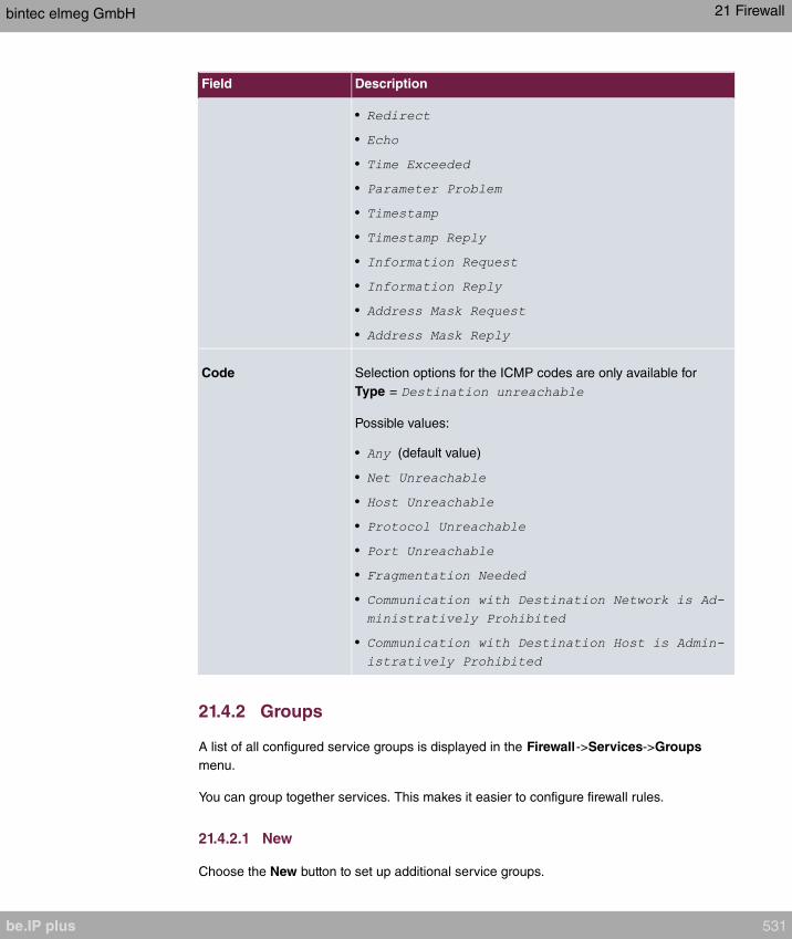
Field Description
•
•
•
•
•
•
•
•
•
•
Code Selection options for the ICMP codes are only available for
Type =
Possible values:
• (default value)
•
•
•
•
•
•
•
21.4.2 Groups
A list of all configured service groups is displayed in the Firewall->Services->Groups
menu.
You can group together services. This makes it easier to configure firewall rules.
21.4.2.1 New
Choose the New button to set up additional service groups.
bintec elmeg GmbH 21 Firewall
be.IP plus 531

The menu Firewall->Services->Groups->New consists of the following fields:
Fields in the Basic Parameters menu.
Field Description
Description Enter the desired description of the service group.
Members Select the members of the group from the available service ali-
ases. To do this, activate the Fields in the Selection column.
21.5 Configuration
21.5.1 SIF - Configuration example
Requirements
• Internet connection
• Your LAN must be connected to one of ports 1, 2, 3 or 4 on the gateway.
Example scenario
Configuration target
• Only certain Internet services are to be available for the staff of a company (HTTP, HT-
TPS, FTP, DNS).
• The gateway should operate as a DNS proxy, which means that the clients use the gate-
way as a DNS server.
• Only the system administrator and the director should be able to established an HTTP
and a Telnet connection to the gateway.
21 Firewall bintec elmeg GmbH
532 be.IP plus

• The director must be able to use all services in the Internet..
• All other data traffic will be blocked.
Important
An incorrect configuration of the firewall can significantly disrupt the functionality of the
gateway or drop the connections.
The usual principle for firewalls also applies: Everything that is not explicitly allowed is
prohibited.
This means accurate planning of the filter rules and filter rule chain is necessary to en-
sure correct operation.
Overview of Configuration Steps
Aliases for IP addresses and network address
Field Menu Value
Description Firewall-> Addresses ->Ad-
dress List-> New
e.g.
Address Type Firewall ->Addresses-> Ad-
dress List ->New
Address / Subnet Firewall-> Addresses ->Ad-
dress List-> New
e.g.
with
Description Firewall-> Addresses ->Ad-
dress List ->New
e.g.
Address Type Firewall-> Addresses ->Ad-
dress List-> New
Address / Subnet Firewall ->Addresses-> Ad-
dress List ->New
e.g.
with
Description Firewall-> Addresses ->Ad-
dress List-> New
e.g.
Address Type Firewall-> Addresses ->Ad-
dress List ->New
Address / Subnet Firewall-> Addresses ->Ad-
dress List-> New
e.g.
with
Description Firewall ->Addresses-> Ad-
dress List ->New
e.g.
bintec elmeg GmbH 21 Firewall
be.IP plus 533

Field Menu Value
Address Type Firewall-> Addresses ->Ad-
dress List-> New
Address / Subnet Firewall-> Addresses ->Ad-
dress List ->New
e.g.
with
Address groups
Field Menu Value
Description Gro
Firewall->Addresses->ups-
>New
e.g.
IP Version Gro
Firewall->Addresses->ups-
>New
Selection Gro
Firewall->Addresses->ups-
>New
e.g. and
Service Sets
Field Menu Value
Description Group
Ne
Firewall->Services->s->w
e.g.
Members Group
Ne
Firewall->Services->s->w
e.g. , and
Description Group
Ne
Firewall->Services->s->w
e.g.
Members Group
Ne
Firewall->Services->s->w
e.g. and
Filter rules 1: Manage Gateway (System administrator)
Field Menu Value
Source Location Firewall ->Policies ->IPv4
Filter Rules-> New
Destination Firewall-> Policies ->IPv4
Filter Rules-> New
21 Firewall bintec elmeg GmbH
534 be.IP plus
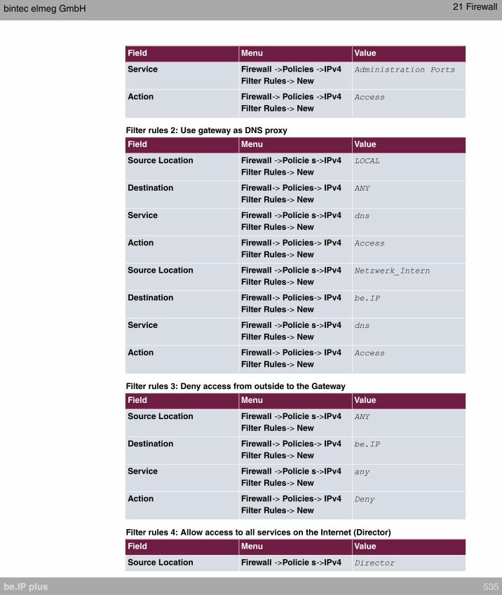
Field Menu Value
Service Firewall ->Policies ->IPv4
Filter Rules-> New
Action Firewall-> Policies ->IPv4
Filter Rules-> New
Filter rules 2: Use gateway as DNS proxy
Field Menu Value
Source Location Firewall ->Policie s->IPv4
Filter Rules-> New
Destination Firewall-> Policies-> IPv4
Filter Rules-> New
Service Firewall ->Policie s->IPv4
Filter Rules-> New
Action Firewall-> Policies-> IPv4
Filter Rules-> New
Source Location Firewall ->Policie s->IPv4
Filter Rules-> New
Destination Firewall-> Policies-> IPv4
Filter Rules-> New
Service Firewall ->Policie s->IPv4
Filter Rules-> New
Action Firewall-> Policies-> IPv4
Filter Rules-> New
Filter rules 3: Deny access from outside to the Gateway
Field Menu Value
Source Location Firewall ->Policie s->IPv4
Filter Rules-> New
Destination Firewall-> Policies-> IPv4
Filter Rules-> New
Service Firewall ->Policie s->IPv4
Filter Rules-> New
Action Firewall-> Policies-> IPv4
Filter Rules-> New
Filter rules 4: Allow access to all services on the Internet (Director)
Field Menu Value
Source Location Firewall ->Policie s->IPv4
bintec elmeg GmbH 21 Firewall
be.IP plus 535

Field Menu Value
Filter Rules-> New
Destination Firewall-> Policies-> IPv4
Filter Rules-> New
Service Firewall ->Policie s->IPv4
Filter Rules-> New
Action Firewall-> Policies-> IPv4
Filter Rules-> New
Filter rules 5: Allow access to the Internet (Staff)
Field Menu Value
Source Location Firewall ->Policie s->IPv4
Filter Rules-> New
Destination Firewall-> Policies-> IPv4
Filter Rules-> New
Service Firewall ->Policie s->IPv4
Filter Rules-> New
Action Firewall-> Policies-> IPv4
Filter Rules-> New
21 Firewall bintec elmeg GmbH
536 be.IP plus
Chapter 22 Local Services
This menu offers services for the following application areas:
• Name resolution (DNS)
• Configuration via web browser (HTTPS)
• Locating of dynamic IP addresses using a DynDNS provider
• Configuration of gateway as a DHCP server (assignment of IP addresses)
• Assignment of incoming and outgoing data and voice calls to authorised users (CAPI
server)
• Automation of tasks according to schedule (scheduling)
• Alive checks for hosts or interfaces, ping tests
• Realtime video/audio conferences (Messenger services, universal plug & play)
• Provision of public Internet accesses (hotspot).
• Start network devices that are switched off via an integrated network card
(Wake-On-LAN)
• Data traffic of a specific interface (Trace Interface)
22.1 DNS
Each device in a TCP/IP network is usually located by its IP address. Because host names
are often used in networks to reach different devices, it is necessary for the associated IP
address to be known. This task can be performed by a DNS server, which resolves the
host names into IP addresses. Alternatively, name resolution can also take place over the
HOSTS file, which is available on all PCs.
Your device offers the following options for name resolution:
• DNS Proxy, for forwarding DNS requests sent to your device to a suitable DNS server.
This also includes specific forwarding of defined domains (Forwarded Domains).
• DNS cache, for saving the positive and negative results of DNS requests.
• Static entries (static hosts), to manually define or prevent assignments of IP addresses to
names.
• DNS monitoring (statistics), to provide an overview of DNS requests on your device.
Name server
bintec elmeg GmbH 22 Local Services
be.IP plus 537

Under Local Services->DNS->DNS Servers->New you enter the IP addresses of name
servers that are queried if your device cannot answer requests itself or by forwarding
entries. Global name servers and name servers that are attached to an interface can both
be entered.
Your device can also receive the name servers attached to an interface dynamically via
PPP or DHCP and transfer them dynamically if necessary.
Strategy for name resolution on your device
A DNS request is handled by your device as follows:
(1) If possible, the request is answered directly from the static or dynamic cache with IP
address or negative response.
(2) Otherwise, if a suitable forwarding entry exists, the relevant DNS server is asked, de-
pending on the configuration of the Internet or dialin connections, if necessary by set-
ting up a WAN connection at extra cost. If the DNS server can resolve the name, the
information is forwarded and a dynamic entry created in the cache.
(3) Otherwise, if name servers have been entered, taking into account the priority con-
figured and if the relevant interface status is "up", the primary DNS server is queried
and then the secondary DNS server. If one of the DNS servers can resolve the name,
the information is forwarded and a dynamic entry created in the cache.
(4) Otherwise, if a suitable Internet or dialin connection is selected as the standard inter-
face, the relevant DNS server is asked, depending on the configuration of the Internet
or dialin connections, if necessary by setting up a WAN connection at extra cost. If
one of the DNS servers can resolve the name, the information is forwarded and a dy-
namic entry created in the cache.
(5) Otherwise, if overwriting the addresses of the global name servers is allowed in the
WAN->Internet + Dialup menu (Interface Mode = ), a connection is set up
– if necessary at extra cost – to the first Internet or dialin connection configured to en-
able DNS server addresses to be requested from DNS servers (DNS Negotiation =
), if this has not been already attempted. When the name servers have been
negotiated successfully, these name servers are then available for more queries.
(6) Otherwise the initial request is answered with a server error.
If one of the DNS servers answers with , the initial request is im-
mediately answered accordingly and a corresponding negative entry is made in the DNS
cache of your device.
22.1.1 Global Settings
The menu Local Services->DNS->Global Settings consists of the following fields:
22 Local Services bintec elmeg GmbH
538 be.IP plus

Fields in the Basic Parameters menu
Field Description
Domain Name Enter the standard domain name of your device.
WINS Server
Primary
Secondary
Enter the IP address of the first and, if necessary, alternative
global Windows Internet Name Server (=WINS) or NetBIOS
Name Server (=NBNS).
The menu Advanced Settings consists of the following fields:
Fields in the Advanced Settings menu
Field Description
Positive Cache Select whether the positive dynamic cache is to be activated,
i.e. successfully resolved names and IP addresses are to be
stored in the cache.
The function is activated by selecting .
The function is enabled by default.
Negative Cache Select whether the negative dynamic cache is to be activated,
i.e. whether queried names for which a DNS server has sent a
negative response are stored as negative entries in the cache.
The function is activated by selecting .
The function is enabled by default.
Cache Size Enter the maximum total number of static and dynamic entries.
Once this value is reached, the dynamic entry not requested for
the longest period of time is deleted when a new entry is added.
Cache Size is reduced by the user, dynamic entries are deleted
if necessary. Statistical entries are not deleted. Cache Size
cannot be set to lower than the current number of static entries.
Possible values: .. .
The default value is .
Maximum TTL for Pos-
itive Cache Entries
Enter the value to which the TTL is to be set for a positive dy-
namic DNS entry in the cache if its TTL is or its TTL exceeds
bintec elmeg GmbH 22 Local Services
be.IP plus 539
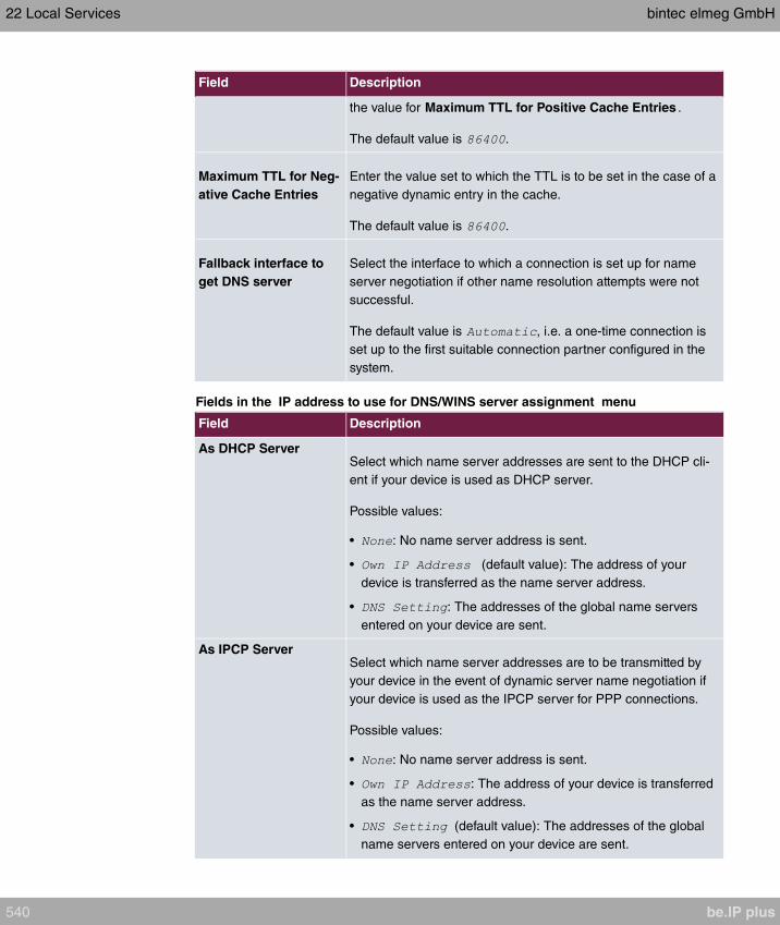
Field Description
the value for Maximum TTL for Positive Cache Entries .
The default value is .
Maximum TTL for Neg-
ative Cache Entries
Enter the value set to which the TTL is to be set in the case of a
negative dynamic entry in the cache.
The default value is .
Fallback interface to
get DNS server
Select the interface to which a connection is set up for name
server negotiation if other name resolution attempts were not
successful.
The default value is , i.e. a one-time connection is
set up to the first suitable connection partner configured in the
system.
Fields in the IP address to use for DNS/WINS server assignment menu
Field Description
As DHCP ServerSelect which name server addresses are sent to the DHCP cli-
ent if your device is used as DHCP server.
Possible values:
• : No name server address is sent.
• (default value): The address of your
device is transferred as the name server address.
• : The addresses of the global name servers
entered on your device are sent.
As IPCP ServerSelect which name server addresses are to be transmitted by
your device in the event of dynamic server name negotiation if
your device is used as the IPCP server for PPP connections.
Possible values:
• : No name server address is sent.
• : The address of your device is transferred
as the name server address.
• (default value): The addresses of the global
name servers entered on your device are sent.
22 Local Services bintec elmeg GmbH
540 be.IP plus

22.1.2 DNS Servers
A list of all configured DNS servers is displayed in the Local Services->DNS->DNS Serv-
ers menu.
22.1.2.1 Edit or New
Choose the icon to edit existing entries. Select the New button to set up additional DNS
servers.
Here you can configure both global DNS servers and DNS servers that are to be assigned
to a particular interface.
Configuring a DNS server for a particular interface can be useful, for example, if accounts
with different providers have been set up via different interfaces and load balancing is be-
ing used.
The Local Services->DNS->DNS Servers->New menu consists of the following fields:
Fields in the Basic Parameters menu.
Field Description
Admin Status Select whether the DNS server should be enabled.
The function is activated by selecting .
The function is enabled by default.
Description Enter a description for DNS server.
Priority Assign a priority to the DNS server.
You can assign more than one pair of DNS servers ( Primary
DNS Server and Secondary DNS Server) to an interface (i. e.
for example, to an Ethernet port or a PPPoE WAN partner) or to
multiple interfaces. The pair with the highest priority is used if
the interface is "up".
Possible values from (highest priority) to (lowest priority).
The default value is .
Interface Mode Select whether the IP addresses of name servers for resolving
the names of Internet addresses are to be obtained automatic-
ally or whether up to two fixed DNS server addresses are to be
bintec elmeg GmbH 22 Local Services
be.IP plus 541

Field Description
entered, depending on the priority.
Possible values:
•
• (default value)
Interface Select the interface to which the DNS server pair is to be as-
signed.
The selected interface is relevant for outgoing DNS requests.
This interface is used for DNS requests directed at the router or
generated by the router itself.
For Interface Mode =
A global DNS server is created with the setting .
For Interface Mode =
A DNS server is configured for all interfaces with the
setting.
IP VersionSelect the IP version used.
Possible values:
•
•
is selected by default.
Primary IPv4 DNS
Server
Only if Interface Mode =
Enter the IPv4 address of the first name server for Internet ad-
dress name resolution.
Secondary IPv4 DNS
Server
Only if Interface Mode =
Optionally, enter the IPv4 address of an alternative name serv-
er.
Primary IPv6 DNS
Server
Only if Interface Mode =
Enter the IPv6 address of the first name server for Internet ad-
22 Local Services bintec elmeg GmbH
542 be.IP plus
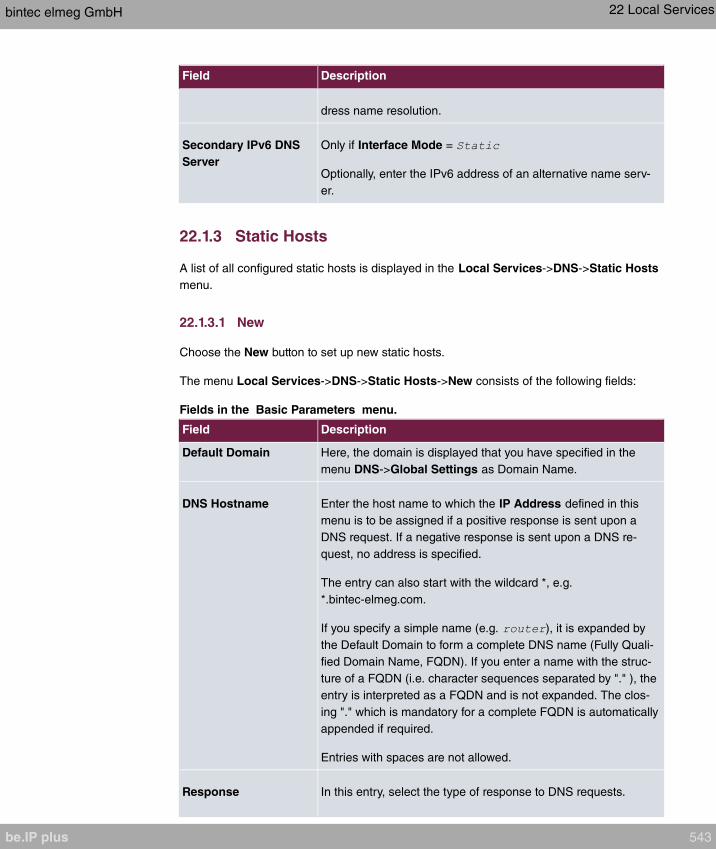
Field Description
dress name resolution.
Secondary IPv6 DNS
Server
Only if Interface Mode =
Optionally, enter the IPv6 address of an alternative name serv-
er.
22.1.3 Static Hosts
A list of all configured static hosts is displayed in the Local Services->DNS->Static Hosts
menu.
22.1.3.1 New
Choose the New button to set up new static hosts.
The menu Local Services->DNS->Static Hosts->New consists of the following fields:
Fields in the Basic Parameters menu.
Field Description
Default Domain Here, the domain is displayed that you have specified in the
menu DNS->Global Settings as Domain Name.
DNS Hostname Enter the host name to which the IP Address defined in this
menu is to be assigned if a positive response is sent upon a
DNS request. If a negative response is sent upon a DNS re-
quest, no address is specified.
The entry can also start with the wildcard *, e.g.
*.bintec-elmeg.com.
If you specify a simple name (e.g. ), it is expanded by
the Default Domain to form a complete DNS name (Fully Quali-
fied Domain Name, FQDN). If you enter a name with the struc-
ture of a FQDN (i.e. character sequences separated by "." ), the
entry is interpreted as a FQDN and is not expanded. The clos-
ing "." which is mandatory for a complete FQDN is automatically
appended if required.
Entries with spaces are not allowed.
Response In this entry, select the type of response to DNS requests.
bintec elmeg GmbH 22 Local Services
be.IP plus 543
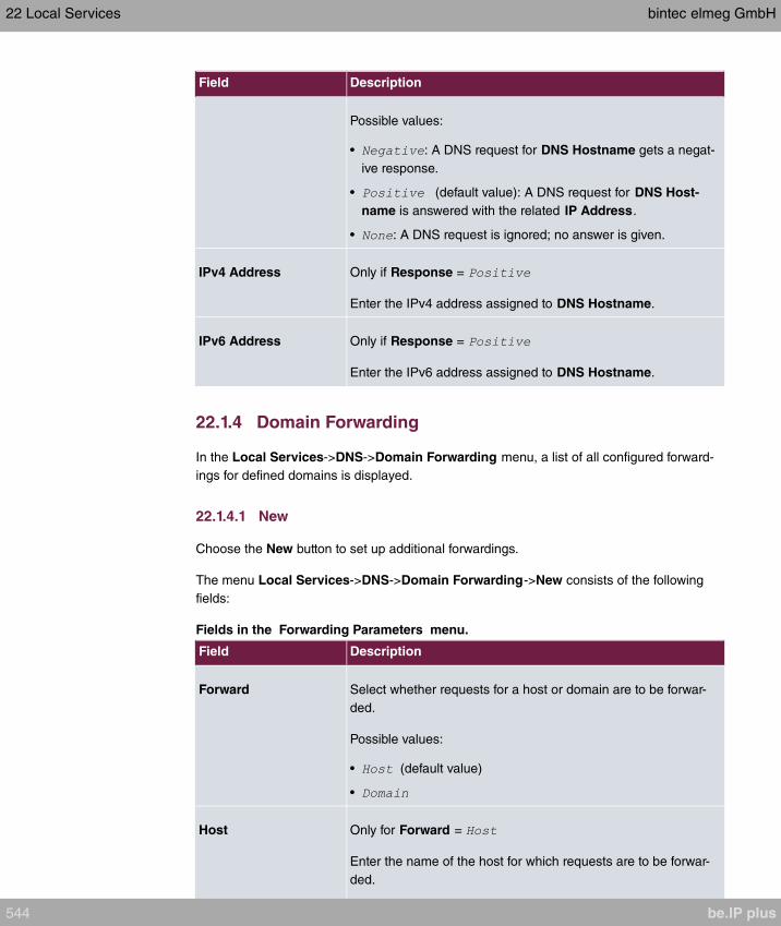
Field Description
Possible values:
• : A DNS request for DNS Hostname gets a negat-
ive response.
• (default value): A DNS request for DNS Host-
name is answered with the related IP Address.
• : A DNS request is ignored; no answer is given.
IPv4 Address Only if Response =
Enter the IPv4 address assigned to DNS Hostname.
IPv6 Address Only if Response =
Enter the IPv6 address assigned to DNS Hostname.
22.1.4 Domain Forwarding
In the Local Services->DNS->Domain Forwarding menu, a list of all configured forward-
ings for defined domains is displayed.
22.1.4.1 New
Choose the New button to set up additional forwardings.
The menu Local Services->DNS->Domain Forwarding->New consists of the following
fields:
Fields in the Forwarding Parameters menu.
Field Description
Forward Select whether requests for a host or domain are to be forwar-
ded.
Possible values:
• (default value)
•
Host Only for Forward =
Enter the name of the host for which requests are to be forwar-
ded.
22 Local Services bintec elmeg GmbH
544 be.IP plus
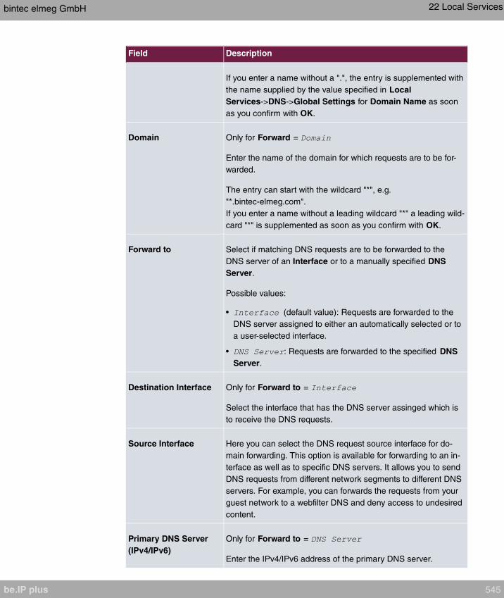
Field Description
If you enter a name without a ".", the entry is supplemented with
the name supplied by the value specified in Local
Services->DNS->Global Settings for Domain Name as soon
as you confirm with OK.
Domain Only for Forward =
Enter the name of the domain for which requests are to be for-
warded.
The entry can start with the wildcard "*", e.g.
"*.bintec-elmeg.com".
If you enter a name without a leading wildcard "*" a leading wild-
card "*" is supplemented as soon as you confirm with OK.
Forward to Select if matching DNS requests are to be forwarded to the
DNS server of an Interface or to a manually specified DNS
Server.
Possible values:
• (default value): Requests are forwarded to the
DNS server assigned to either an automatically selected or to
a user-selected interface.
• : Requests are forwarded to the specified DNS
Server.
Destination Interface Only for Forward to =
Select the interface that has the DNS server assinged which is
to receive the DNS requests.
Source Interface Here you can select the DNS request source interface for do-
main forwarding. This option is available for forwarding to an in-
terface as well as to specific DNS servers. It allows you to send
DNS requests from different network segments to different DNS
servers. For example, you can forwards the requests from your
guest network to a webfilter DNS and deny access to undesired
content.
Primary DNS Server
(IPv4/IPv6)
Only for Forward to =
Enter the IPv4/IPv6 address of the primary DNS server.
bintec elmeg GmbH 22 Local Services
be.IP plus 545
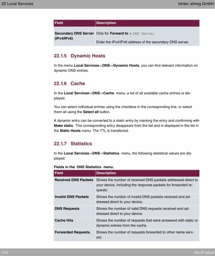
Field Description
Secondary DNS Server
(IPv4/IPv6)
Only for Forward to =
Enter the IPv4/IPv6 address of the secondary DNS server.
22.1.5 Dynamic Hosts
In the menu Local Services->DNS->Dynamic Hosts, you can find relevant information on
dynamic DNS entries.
22.1.6 Cache
In the Local Services->DNS->Cache menu, a list of all available cache entries is dis-
played.
You can select individual entries using the checkbox in the corresponding line, or select
them all using the Select all button.
A dynamic entry can be converted to a static entry by marking the entry and confirming with
Make static. This corresponding entry disappears from the list and is displayed in the list in
the Static Hosts menu. The TTL is transferred.
22.1.7 Statistics
In the Local Services->DNS->Statistics menu, the following statistical values are dis-
played:
Fields in the DNS Statistics menu.
Field Description
Received DNS Packets Shows the number of received DNS packets addressed direct to
your device, including the response packets for forwarded re-
quests.
Invalid DNS Packets Shows the number of invalid DNS packets received and ad-
dressed direct to your device.
DNS Requests Shows the number of valid DNS requests received and ad-
dressed direct to your device.
Cache Hits Shows the number of requests that were answered with static or
dynamic entries from the cache.
Forwarded Requests Shows the number of requests forwarded to other name serv-
ers.
22 Local Services bintec elmeg GmbH
546 be.IP plus
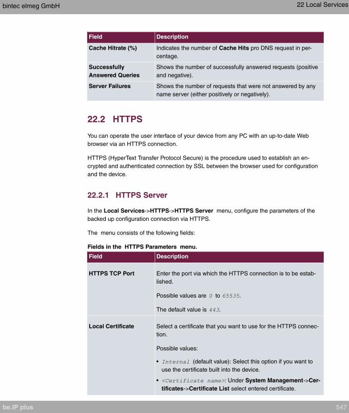
Field Description
Cache Hitrate (%) Indicates the number of Cache Hits pro DNS request in per-
centage.
Successfully
Answered Queries
Shows the number of successfully answered requests (positive
and negative).
Server Failures Shows the number of requests that were not answered by any
name server (either positively or negatively).
22.2 HTTPS
You can operate the user interface of your device from any PC with an up-to-date Web
browser via an HTTPS connection.
HTTPS (HyperText Transfer Protocol Secure) is the procedure used to establish an en-
crypted and authenticated connection by SSL between the browser used for configuration
and the device.
22.2.1 HTTPS Server
In the Local Services->HTTPS->HTTPS Server menu, configure the parameters of the
backed up configuration connection via HTTPS.
The menu consists of the following fields:
Fields in the HTTPS Parameters menu.
Field Description
HTTPS TCP Port Enter the port via which the HTTPS connection is to be estab-
lished.
Possible values are to .
The default value is .
Local Certificate Select a certificate that you want to use for the HTTPS connec-
tion.
Possible values:
• (default value): Select this option if you want to
use the certificate built into the device.
• : Under System Management->Cer-
tificates->Certificate List select entered certificate.
bintec elmeg GmbH 22 Local Services
be.IP plus 547

22.3 DynDNS Client
The use of dynamic IP addresses has the disadvantage that a host in the network can no
longer be found once its IP address has changed. DynDNS ensures that your device can
still be reached after a change to the IP address.
The following configuration steps are necessary:
• Registration of a host name at a DynDNS provider
• Configuration of your device
Registration
The registration of a host name means that you define an individual user name for the
DynDNS service, e.g. . The service providers offer various domain names for
this, so that a unique host name results for your device , e.g.
. The DynDNS provider relieves you of the task of answer-
ing all DNS requests concerning the host with the dynamic
IP address of your device.
To ensure that the provider always knows the current IP address of your device, your
device contacts the provider when setting up a new connection and propagates its present
IP address.
22.3.1 DynDNS Update
In the Local Services->DynDNS Client->DynDNS Update menu, a list of all configured
DynDNS registrations for updating is displayed
22.3.1.1 New
Choose the New button to set up further DynDNS registrations to be updated.
The menu Local Services->DynDNS Client->DynDNS Update->New consists of the fol-
lowing fields:
Fields in the Basic Parameters menu.
Field Description
Host Name Enter the complete host name exactly as registered with the
DynDNS provider.
22 Local Services bintec elmeg GmbH
548 be.IP plus
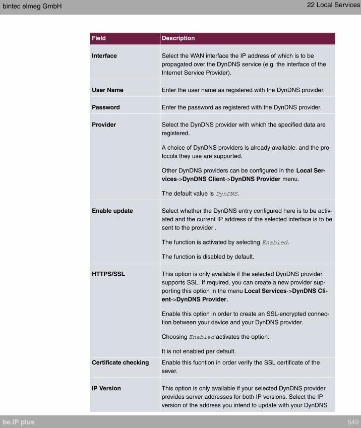
Field Description
Interface Select the WAN interface the IP address of which is to be
propagated over the DynDNS service (e.g. the interface of the
Internet Service Provider).
User Name Enter the user name as registered with the DynDNS provider.
Password Enter the password as registered with the DynDNS provider.
Provider Select the DynDNS provider with which the specified data are
registered.
A choice of DynDNS providers is already available. and the pro-
tocols they use are supported.
Other DynDNS providers can be configured in the Local Ser-
vices->DynDNS Client->DynDNS Provider menu.
The default value is .
Enable update Select whether the DynDNS entry configured here is to be activ-
ated and the current IP address of the selected interface is to be
sent to the provider .
The function is activated by selecting .
The function is disabled by default.
HTTPS/SSL This option is only available if the selected DynDNS provider
supports SSL. If required, you can create a new provider sup-
porting this option in the menu Local Services->DynDNS Cli-
ent->DynDNS Provider.
Enable this option in order to create an SSL-encrypted connec-
tion between your device and your DynDNS provider.
Choosing activates the option.
It is not enabled per default.
Certificate checking Enable this fucntion in order verify the SSL certificate of the
sever.
IP Version This option is only available if your selected DynDNS provider
provides server addresses for both IP versions. Select the IP
version of the address you intend to update with your DynDNS
bintec elmeg GmbH 22 Local Services
be.IP plus 549

Field Description
provider.
Possible values:
IPv4
IPv6.
In order to update the IPv4 as well as the Pv6 address of an in-
terface, create two entries with otherwise identical settings. In-
quire with your service provider if they support multiple updates!
The menu Advanced Settings consists of the following fields:
Fields in the Advanced Settings menu.
Field Description
Mail Exchanger (MX) Enter the full host name of a mail server to which e-mails are to
be forwarded if the host currently configured is not to receive
mail.
Ask your provider about this forwarding service and make sure
e-mails can be received from the host entered as MX.
Wildcard Select whether forwarding of all subdomains of the Host Name
is to be enabled for the current IP address of the Interface
(advanced name resolution).
The function is activated by selecting .
The function is disabled by default.
22.3.2 DynDNS Provider
A list of all configured DynDNS providers is displayed in the Local Services->DynDNS Cli-
ent->DynDNS Provider menu.
22.3.2.1 New
Choose the New button to set up new DynDNS providers.
The menu Local Services->DynDNS Client->DynDNS Provider->New consists of the fol-
lowing fields:
22 Local Services bintec elmeg GmbH
550 be.IP plus
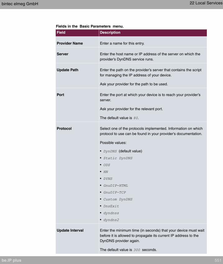
Fields in the Basic Parameters menu.
Field Description
Provider Name Enter a name for this entry.
Server Enter the host name or IP address of the server on which the
provider’s DynDNS service runs.
Update Path Enter the path on the provider’s server that contains the script
for managing the IP address of your device.
Ask your provider for the path to be used.
Port Enter the port at which your device is to reach your provider’s
server.
Ask your provider for the relevant port.
The default value is .
Protocol Select one of the protocols implemented. Information on which
protocol to use can be found in your provider's documentation.
Possible values:
• (default value)
•
•
•
•
•
•
•
•
•
•
Update Interval Enter the minimum time (in seconds) that your device must wait
before it is allowed to propagate its current IP address to the
DynDNS provider again.
The default value is seconds.
bintec elmeg GmbH 22 Local Services
be.IP plus 551
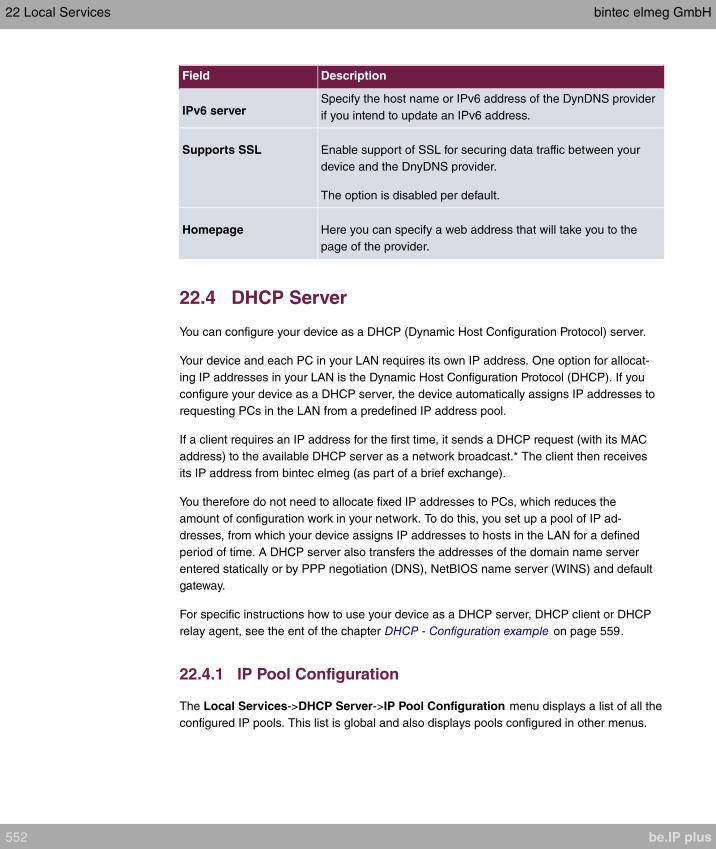
Field Description
IPv6 serverSpecify the host name or IPv6 address of the DynDNS provider
if you intend to update an IPv6 address.
Supports SSL Enable support of SSL for securing data traffic between your
device and the DnyDNS provider.
The option is disabled per default.
Homepage Here you can specify a web address that will take you to the
page of the provider.
22.4 DHCP Server
You can configure your device as a DHCP (Dynamic Host Configuration Protocol) server.
Your device and each PC in your LAN requires its own IP address. One option for allocat-
ing IP addresses in your LAN is the Dynamic Host Configuration Protocol (DHCP). If you
configure your device as a DHCP server, the device automatically assigns IP addresses to
requesting PCs in the LAN from a predefined IP address pool.
If a client requires an IP address for the first time, it sends a DHCP request (with its MAC
address) to the available DHCP server as a network broadcast.* The client then receives
its IP address from bintec elmeg (as part of a brief exchange).
You therefore do not need to allocate fixed IP addresses to PCs, which reduces the
amount of configuration work in your network. To do this, you set up a pool of IP ad-
dresses, from which your device assigns IP addresses to hosts in the LAN for a defined
period of time. A DHCP server also transfers the addresses of the domain name server
entered statically or by PPP negotiation (DNS), NetBIOS name server (WINS) and default
gateway.
For specific instructions how to use your device as a DHCP server, DHCP client or DHCP
relay agent, see the ent of the chapter DHCP - Configuration example on page 559.
22.4.1 IP Pool Configuration
The Local Services->DHCP Server->IP Pool Configuration menu displays a list of all the
configured IP pools. This list is global and also displays pools configured in other menus.
22 Local Services bintec elmeg GmbH
552 be.IP plus

22.4.1.1 Edit or New
Choose the New button to set up new IP address pools. Choose the icon to edit exist-
ing entries.
Fields in the menu Basic Parameters
Field Description
IP Pool Name Enter any description to uniquely identify the IP pool.
IP Address Range Enter the first (first field) and last (second field) IP address of
the IP address pool.
DNS Server Primary: Enter the IP address of the DNS server that is to be
used, preferably, by clients who draw an address from this pool.
Secondary: Optionally, enter the IP address of an alternative
DNS server.
22.4.2 DHCP Configuration
To activate your device as a DHCP server, you must first define IP address pools from
which the IP addresses are distributed to the requesting clients.
A list of all configured DHCP pools is displayed in the Local Services->DHCP
Server->DHCP Configuration menu.
In the list, for each entry, you have the possibility under Status of enabling or disabling the
configured DHCP pools.
Note
In the ex works state the DHCP pool is preconfigured with the IP addresses
192.168.0.10 to 192.168.0.49 and is used if there is no other DHCP server available in
the network.
22.4.2.1 Edit or New
Choose the New button to set up new DHCP pools. Choose the icon to edit existing
entries.
The Local Services->DHCP Server->DHCP Configuration->New menu consists of the
bintec elmeg GmbH 22 Local Services
be.IP plus 553

following fields:
Fields in the menu Basic Parameters
Field Description
Interface Select the interface over which the addresses defined in IP
Pool Name are to be assigned to DHCP clients.
When a DHCP request is received over this Interface, one of
the addresses from the address pool is assigned.
IP Pool Name Select an IP pool name configured in the Local Services->DH-
CP Server->IP Pool Configuration menu.
Pool Usage Select if the DHCP pool is to be used for requests from clients
in a network directly connected to an Ethernet interface, or if it is
to be used for DHCP requests from a remote network that are
sent to your device via a DHCP relay station.
In the second case, it is possible to use an IP address pool for
the remote network.
Possible values:
• (default value): The DHCP pool is only used for DHCP
requests from a network directly connected to an Ethernet in-
terface.
• : The DHCP pool is only used for DHCP requests for-
warded from remote networks.
• : The DHCP pool can be used for both kinds of
requests.
DescriptionEnter any description to uniquely identify the DHCP pool.
The menu Advanced Settings consists of the following fields:
Fields in the menu Advanced Settings
Field Description
Gateway Select which IP address is to be transferred to the DHCP client
as gateway.
Possible values:
• (default value): Here, the IP ad-
dress defined for the Interface is transferred.
22 Local Services bintec elmeg GmbH
554 be.IP plus

Field Description
• : No IP address is sent.
• : Enter the corresponding IP address.
Lease Time Enter the length of time (in minutes) for which an address from
the pool is to be assigned to a host.
After the Lease Time expires, the address can be reassigned
by the server.
The default value is .
DHCP Options Specify which additional data is forwarded to the DHCP client.
Possible values for Option:
• (default value): Enter the IP address of the
time server to be sent to the client.
• : Enter the IP address of the DNS server to be
sent to the client.
• : Enter the DNS domain to be sent to the
client.
• : Enter the IP address of the WINS/
NBNS server to be sent to the client.
• : Select the type of the WINS/NBT
node to be sent to the client.
• : Enter the IP address of the TFTP server to be
sent to the client.
• : Enter the IP address of the CAPWAP
controller to be sent to the client.
• : This option enables you to
send a client any URL.
Use this option to send querying IP1x0 telephones the URL of
the provisioning server if the telephones are to be provisioned
automatically. The URL then needs to take the form
.
Multiple entries are possible. Add additional entries with the
Add button.
bintec elmeg GmbH 22 Local Services
be.IP plus 555
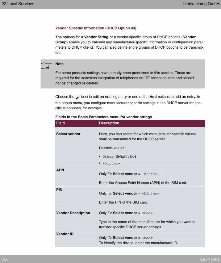
Vendor Specific Information (DHCP Option 43)
The options for a Vendor String or a vendor-specific group of DHCP options ( Vendor
Group) enable you to transmit any manufacturer-specific information or configuration para-
meters to DHCP clients. You can also define entire groups of DHCP options to be transmit-
ted.
Note
For some products settings have already been predefined in this section. These are
required for the seamless integration of telephones or LTE access routers and should
not be changed or deleted.
Choose the icon to edit an existing entry or one of the Add buttons to add an entry. In
the popup menu, you configure manufacturer-specific settings in the DHCP server for spe-
cific telephones, for example.
Fields in the Basic Parameters menu for vendor strings
Field Description
Select vendor Here, you can select for which manufacturer specific values
shall be transmitted for the DHCP server.
Possible values:
• (default value)
•
APNOnly für Select vendor =
Enter the Access Point Namen (APN) of the SIM card.
PINOnly für Select vendor =
Enter the PIN of the SIM card.
Vendor Description Only für Select vendor =
Type in the name of the manufacturer for which you want to
transfer specific DHCP server settings.
Vendor IDOnly für Select vendor =
To identify the device, enter the manufacturer ID.
22 Local Services bintec elmeg GmbH
556 be.IP plus

Field Description
Vendor Option StringOnly für Select vendor =
Enter the manufacturer specific configuration parameters.
Fields in the Basic Parameters menu for vendor groups
Field Description
Select vendor Here, you can select for which manufacturer specific values
shall be transmitted for the DHCP server.
Possible values:
• (default value)
•
Provisioning Server Only für Select vendor =
Enter which manufacturer value shall be transmitted.
For the setting Select vendor = , the default value
is displayed.
You can complete the IP address of the desired server.
Vendor Description Only für Select vendor =
Type in the name of the manufacturer for which you want to
transfer specific DHCP server settings.
Vendor IDOnly für Select vendor =
To identify the device, enter the manufacturer ID.
Custom DHCP Options Only für Select vendor =
Use Add to add more entries.
You can add custom DHCP options.
22.4.3 IP/MAC Binding
The Local Services->DHCP Server->IP/MAC Binding menu displays a list of all clients
that received an IP address from your device via DHCP.
You can allocate an IP address from a defined IP address pool to specific MAC addresses.
bintec elmeg GmbH 22 Local Services
be.IP plus 557

You can do this by selecting the Static Binding option in the list to convert a list entry as a
fixed binding, or you manually create a fixed IP/MAC binding by configuring this in the New
sub-menu.
Note
You can only create new static IP/MAC bindings if IP address ranges were configured
in Local Services->DHCP Server->DHCP Pool, and in the Local Services->DHCP
Server->IP Pool Configuration menu is assigned a valid IP Pool.
22.4.3.1 New
Choose the New button to set up new IP/MAC bindings.
The menu Local Services->DHCP Server->IP/MAC Binding->New consists of the follow-
ing fields:
Fields in the Basic Parameters menu.
Field Description
Description Enter the name of the host to which the MAC Address the IP
Address is to be bound.
A character string of up to 256 characters is possible.
IP Address Enter the IP address to be assigned to the MAC address spe-
cified in MAC Address is to be assigned.
MAC Address Enter the MAC address to which the IP address specified in IP
Address is to be assigned.
22.4.4 DHCP Relay Settings
If your device for the local network does not distribute any IP addresses to the clients by
DHCP, it can still forward the DHCP requests on behalf of the local network to a remote
DHCP server. The DHCP server then assigns the your device an IP address from its pool,
which in turn sends this to the client in the local network.
The menu Local Services->DHCP Server->DHCP Relay Settings consists of the follow-
ing fields:
Fields in the Basic Parameters menu.
22 Local Services bintec elmeg GmbH
558 be.IP plus
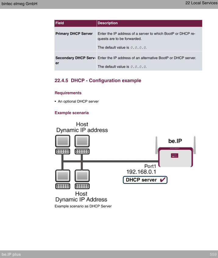
Field Description
Primary DHCP Server Enter the IP address of a server to which BootP or DHCP re-
quests are to be forwarded.
The default value is .
Secondary DHCP Serv-
er
Enter the IP address of an alternative BootP or DHCP server.
The default value is .
22.4.5 DHCP - Configuration example
Requirements
• An optional DHCP server
Example scenaria
Example scenario as DHCP Server
bintec elmeg GmbH 22 Local Services
be.IP plus 559

Example scenario as DHCP Client
22 Local Services bintec elmeg GmbH
560 be.IP plus

Example scenario as DHCP Relay Server
Configuration target
You can use your device as a DHCP server, DHCP client or DHCP relay agent.
Overview of Configuration Steps
DHCP Server
Field Menu Value
IP Pool Name Local Services->DHCP Server->IP
Pool Configuration->New
e.g.
IP Address Range Local Services->DHCP Server->IP
Pool Configuration->New
e.g. and
Interface Local Services->DHCP Server->DH-
CP Configuration->New
e.g.
IP Pool Name Local Services->DHCP Server->DH-
CP Configuration->New
Pool Usage Local Services->DHCP Server->DH-
CP Configuration->New
bintec elmeg GmbH 22 Local Services
be.IP plus 561

Field Menu Value
Gateway Local Services->DHCP Server->DH-
CP Configuration->New->Ad-
vanced Settings
Lease Time Local Services->DHCP Server->DH-
CP Configuration->New->Ad-
vanced Settings
e.g.
IP address to use for
DNS/WINS server as-
signment
Local Services->DNS->Global Set-
tings->Advanced Settings
e.g.
DHCP Client
Field Menu Value
Address Mode LAN->IP Configuration->Interfaces-
> <en1-4>->
DHCP MAC Address
(optional)
LAN->IP Configuration->Interfaces-
> <en1-4> -> ->Advanced Set-
tings
MAC address for a spe-
cific DHCP server
DHCP Relay Server
Field Menu Value
Primary DHCP Server Local Services->DHCP Server->DH-
CP Relay Settings
e.g.
Secondary DHCP Serv-
er (optional)
Local Services->DHCP Server->DH-
CP Relay Settings
if one exists
22.5 DHCPv6 Server
You can operate your device as a DHCPv6 server. The DHCPv6 server can either assign
IP addresses as well as DHCPv6 options or DHCPv6 options only without any addresses.
These parameters are collected in a so called "Option Set". An option set can be linked to
an interface (see Local Services->DHCPv6 Server->DHCPv6 Server->New), or it can be
configured globally (see Local Services->DHCPv6 Server->DHCPv6 Global
Options->New). DHCP options can, e.g., contain information about DNS or time servers.
22 Local Services bintec elmeg GmbH
562 be.IP plus

Note
An IPv6 address pool is created by assigning an IPv6 Link Prefix (a subnet with a
length of /64) to an DHCPv6 option set. The definition of a separate set of IP ad-
dresses like, e.g. fc00:1:2:3::1..fc00:1:2:3::100, is - in contrast with IPv4 - not specified
for IPv6.
The following requirements must be met for the configuration of an IPV6 address pool:
(a) IPv6 has to be activated for the respective interface.
(b) An IPv6 Link Prefix (subnet) with a length of /64 has to be configured for the respective
interface. An IPv6 link prefix can be defined in either of two ways:
• The IPv6 Link Prefix is derived from a General IPv6 Prefix (a prefix with a length of,
e.g., /56 or /48). In this case, the General IPv6 Prefix has to be configured in the
menu Networking->IPv6 General Prefixes->General Prefix Configuration .
• The IPv6 Link Prefix with a length of /64 is manually configured for the respective in-
terface and is not derived from a General IPv6 Prefix.
(c) The DHCP Server option has to be enabled for the interface.
Moreover, the following settings are recommended:
• The options Preferred Lifetime and Valid Lifetime should be set to values higher than
the value configured for the option Router Lifetime.
With a Router Lifetime of 600 seconds a Preferred Lifetime of, e.g., 900 seconds and a
Valid Lifetime of 1800 seconds are reasonable settings.
• The option DHCP Mode should be enabled.
In order to make the settings mentioned above, go to the menu LAN->IP
Configuration->Interfaces. Choose the intended interface with the icon. Activate IPv6
and set the IPv6 Mode to . In the field
IPv6-Adressen, click Add and configure the Link Prefix. Confirm your configuration with
Accept. The configuration of the recommended settings s then carried out in the following
menus:
• Router Lifetime: LAN->IP Configuration->Interfaces->New->Advanced
Settings->Advanced IPv6 Settings
• Preferred Lifetime and Valid Lifetime: LAN->IP
Configuration->Interfaces->New->Basic IPv6 Parameters->Add->Advanced
bintec elmeg GmbH 22 Local Services
be.IP plus 563
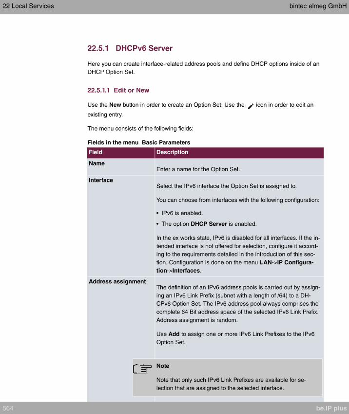
22.5.1 DHCPv6 Server
Here you can create interface-related address pools and define DHCP options inside of an
DHCP Option Set.
22.5.1.1 Edit or New
Use the New button in order to create an Option Set. Use the icon in order to edit an
existing entry.
The menu consists of the following fields:
Fields in the menu Basic Parameters
Field Description
NameEnter a name for the Option Set.
InterfaceSelect the IPv6 interface the Option Set is assigned to.
You can choose from interfaces with the following configuration:
• IPv6 is enabled.
• The option DHCP Server is enabled.
In the ex works state, IPv6 is disabled for all interfaces. If the in-
tended interface is not offered for selection, configure it accord-
ing to the requirements detailed in the introduction of this sec-
tion. Configuration is done on the menu LAN->IP Configura-
tion->Interfaces.
Address assignmentThe definition of an IPv6 address pools is carried out by assign-
ing an IPv6 Link Prefix (subnet with a length of /64) to a DH-
CPv6 Option Set. The IPv6 address pool always comprises the
complete 64 Bit address space of the selected IPv6 Link Prefix.
Address assignment is random.
Use Add to assign one or more IPv6 Link Prefixes to the IPv6
Option Set.
Note
Note that only such IPv6 Link Prefixes are available for se-
lection that are assigned to the selected interface.
22 Local Services bintec elmeg GmbH
564 be.IP plus
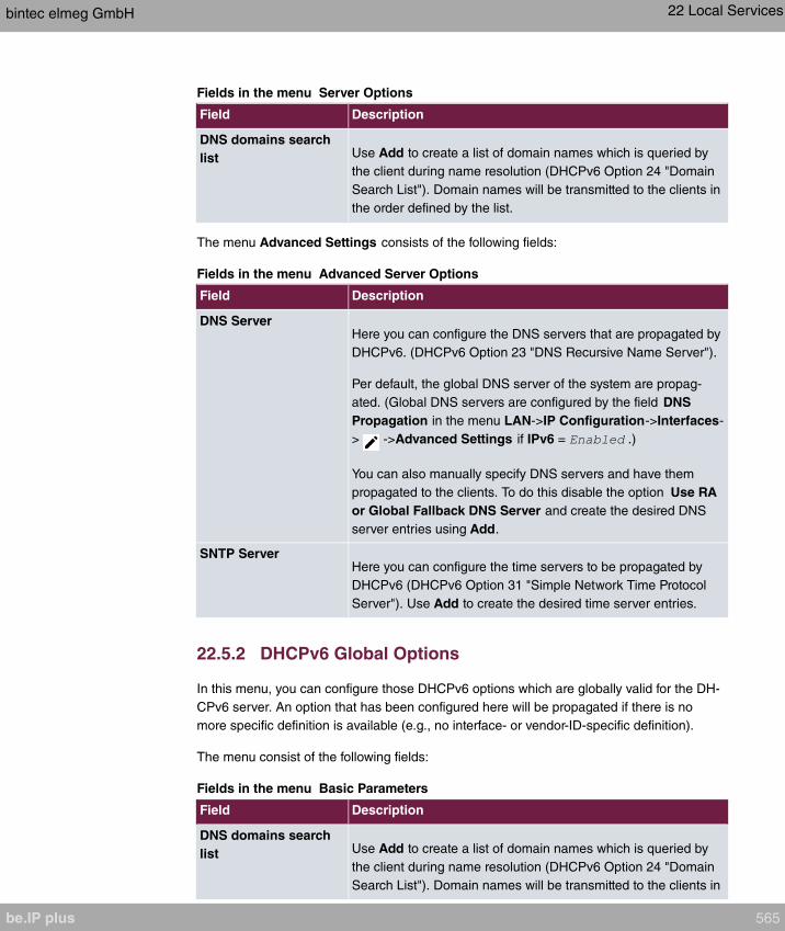
Fields in the menu Server Options
Field Description
DNS domains search
list Use Add to create a list of domain names which is queried by
the client during name resolution (DHCPv6 Option 24 "Domain
Search List"). Domain names will be transmitted to the clients in
the order defined by the list.
The menu Advanced Settings consists of the following fields:
Fields in the menu Advanced Server Options
Field Description
DNS ServerHere you can configure the DNS servers that are propagated by
DHCPv6. (DHCPv6 Option 23 "DNS Recursive Name Server").
Per default, the global DNS server of the system are propag-
ated. (Global DNS servers are configured by the field DNS
Propagation in the menu LAN->IP Configuration->Interfaces-
> ->Advanced Settings if IPv6 = .)
You can also manually specify DNS servers and have them
propagated to the clients. To do this disable the option Use RA
or Global Fallback DNS Server and create the desired DNS
server entries using Add.
SNTP ServerHere you can configure the time servers to be propagated by
DHCPv6 (DHCPv6 Option 31 "Simple Network Time Protocol
Server"). Use Add to create the desired time server entries.
22.5.2 DHCPv6 Global Options
In this menu, you can configure those DHCPv6 options which are globally valid for the DH-
CPv6 server. An option that has been configured here will be propagated if there is no
more specific definition is available (e.g., no interface- or vendor-ID-specific definition).
The menu consist of the following fields:
Fields in the menu Basic Parameters
Field Description
DNS domains search
list Use Add to create a list of domain names which is queried by
the client during name resolution (DHCPv6 Option 24 "Domain
Search List"). Domain names will be transmitted to the clients in
bintec elmeg GmbH 22 Local Services
be.IP plus 565
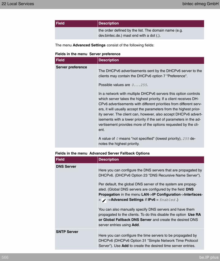
Field Description
the order defined by the list. The domain name (e.g.
dev.bintec.de.) mast end with a dot (.).
The menu Advanced Settings consist of the following fields:
Fields in the menu Server preference
Field Description
Server preferenceThe DHCPv6 advertisements sent by the DHCPv6 server to the
clients may contain the DHCPv6 option 7 "Preference".
Possible values are .
In a network with multiple DHCPv6 servers this option controls
which server takes the highest priority. If a client receives DH-
CPv6 advertisements with different priorities from different serv-
ers, it will usually accept the parameters from the highest prior-
ity server. The client can, however, also accept DHCPv6 advert-
isements with a lower priority if the set of parameters in the ad-
vertisement provides more of the options requested by the cli-
ent.
A value of means "not specified" (lowest priority), de-
notes the highest priority.
Fields in the menu Advanced Server Fallback Options
Field Description
DNS ServerHere you can configure the DNS servers that are propagated by
DHCPv6. (DHCPv6 Option 23 "DNS Recursive Name Server").
Per default, the global DNS server of the system are propag-
ated. (Global DNS servers are configured by the field DNS
Propagation in the menu LAN->IP Configuration->Interfaces-
> ->Advanced Settings if IPv6 = .)
You can also manually specify DNS servers and have them
propagated to the clients. To do this disable the option Use RA
or Global Fallback DNS Server and create the desired DNS
server entries using Add.
SNTP ServerHere you can configure the time servers to be propagated by
DHCPv6 (DHCPv6 Option 31 "Simple Network Time Protocol
Server"). Use Add to create the desired time server entries.
22 Local Services bintec elmeg GmbH
566 be.IP plus
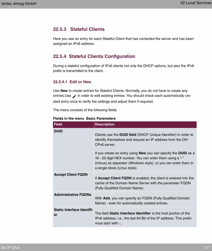
22.5.3 Stateful Clients
Here you see an entry for each Stateful Client that has contacted the server and has been
assigned an IPv6 address.
22.5.4 Stateful Clients Configuration
During a stateful configuration of IPv6 clients not only the DHCP options, but also the IPv6
prefix is transmitted to the client.
22.5.4.1 Edit or New
Use New to create entries for Stateful Clients. Normally, you do not have to create any
entries.Use in order to edit existing entries. You should check each automatically cre-
ated entry once to verify the settings and adjust them if required.
The menu consists of the following fields.
Fields in the menu Basic Parameters
Field Description
DUIDClients use the DUID field (DHCP Unique Identifier) in order to
identify themselves and request an IP address from the DH-
CPv6 server.
If you create an entry using New you can specify the DUID as a
16 - 20 digit HEX number. You can enter them using a "-"
(minus) as separator (Windows style), or you can enter them in
a single block (Linux style).
Accept Client FQDNIf Accept Client FQDN is enabled, the client is entered into the
cache of the Domain Name Server with the parameter FQDN
(Fully Qualified Domain Name).
Administrative FQDNsWith Add, you can specify an FQDN (Fully Qualified Domain
Name) - even for automatically created entries.
Static Interface Identifi-
er The field Static Interface Identifier is the host portion of the
IPv6 address, i.e., the last 64 Bit of the IP address. This prefix
must start with ::.
bintec elmeg GmbH 22 Local Services
be.IP plus 567

22.6 CAPI Server
You can use the CAPI Server function to assign user names and passwords to users of the
CAPI applications on your device. This makes sure that only authorised users can receive
incoming calls and make outgoing calls via CAPI.
The CAPI service allows connection of incoming and outgoing data and voice calls to com-
munications applications on hosts in the LAN that access the Remote CAPI interface of
your device. This enables, for example, hosts connected to your device to receive and
send faxes.
Note
All incoming calls to the CAPI are offered to all registered and "eavesdropping" CAPI
applications in the LAN.
In the ex works state, a user with the user name and no password is
entered for the CAPI subsystem.
Once you've created your intended users with password, you should delete the
user without password.
22.6.1 User
A list of all configured CAPI users is displayed in the Local Services->CAPI Server->User
menu.
22.6.1.1 New
Choose the New button to set up new CAPI users.
The menu Local Services->CAPI Server->User->New consists of the following fields:
Fields in the Basic Parameters menu.
Field Description
User Name Enter the user name for which access to the CAPI service is to
be allowed or denied.
Password Enter the password which the user User Name shall use for
identification to gain access to the CAPI service.
22 Local Services bintec elmeg GmbH
568 be.IP plus

Field Description
Access Select whether access to the CAPI service is to be permitted or
denied for the user.
The function is activated by selecting .
The function is enabled by default.
22.6.2 Options
The menu Local Services->CAPI Server->Options consists of the following fields:
Fields in the Basic Parameters menu.
Field Description
Enable server Select whether your device is to be enabled as a CAPI server.
The function is activated by selecting .
The function is enabled by default.
Faxheader Select whether the fax header should be printed at the top of
outgoing faxes.
The function is activated by selecting .
The function is disabled by default.
CAPI Server TCP Port The field can only be edited if Enable server is enabled.
Enter the TCP port number for remote CAPI connections.
The default value is .
22.7 Scheduling
Your device has an event scheduler which enables certain standard actions (activation or
deactivation of interfaces, for example) to be carried out. In addition, every existing MIB
variable can be configured with any value.
You configure the desired Actions and define the triggers controlling the date and other
conditions of the Actions. A trigger may be a single event or a sequence of events collec-
ted in an Event List. For a single event, create an Event List containing only one element.
bintec elmeg GmbH 22 Local Services
be.IP plus 569
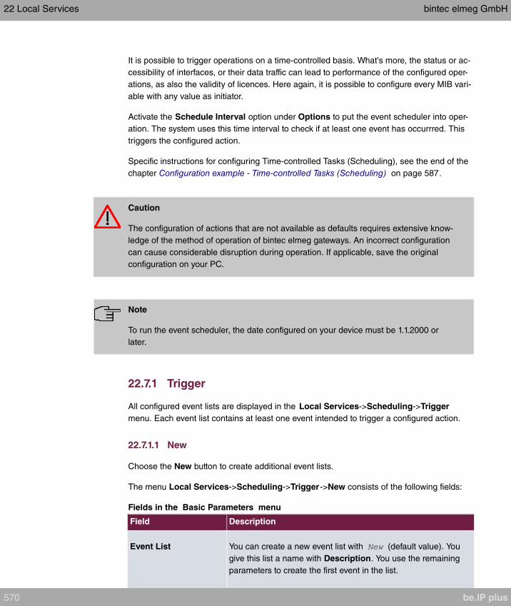
It is possible to trigger operations on a time-controlled basis. What's more, the status or ac-
cessibility of interfaces, or their data traffic can lead to performance of the configured oper-
ations, as also the validity of licences. Here again, it is possible to configure every MIB vari-
able with any value as initiator.
Activate the Schedule Interval option under Options to put the event scheduler into oper-
ation. The system uses this time interval to check if at least one event has occurrred. This
triggers the configured action.
Specific instructions for configuring Time-controlled Tasks (Scheduling), see the end of the
chapter Configuration example - Time-controlled Tasks (Scheduling) on page 587.
Caution
The configuration of actions that are not available as defaults requires extensive know-
ledge of the method of operation of bintec elmeg gateways. An incorrect configuration
can cause considerable disruption during operation. If applicable, save the original
configuration on your PC.
Note
To run the event scheduler, the date configured on your device must be 1.1.2000 or
later.
22.7.1 Trigger
All configured event lists are displayed in the Local Services->Scheduling->Trigger
menu. Each event list contains at least one event intended to trigger a configured action.
22.7.1.1 New
Choose the New button to create additional event lists.
The menu Local Services->Scheduling->Trigger->New consists of the following fields:
Fields in the Basic Parameters menu
Field Description
Event List You can create a new event list with (default value). You
give this list a name with Description. You use the remaining
parameters to create the first event in the list.
22 Local Services bintec elmeg GmbH
570 be.IP plus

Field Description
If you want to add to an existing event list, select the event list
you want and add at least one more event to it.
You can use event lists to create complex conditions for initiat-
ing an action. The events are processed in the same order in
which they are created in the list.
4Description Only for Event List
Enter your chosen designation for the Event List.
Event Type Select the type of initiator.
Possible values:
• (default value): The operations configured and assigned
in Actions are initiated at specific points in time.
• : The operations configured and assigned in Ac-
tions are initiated when the defined MIB variables assumes
the assigned values.
• : Operations configured and assigned in
Actions are initiated, when the defined interfaces take on a
specified status.
• : Operations configured and assigned
in Actions are initiated when the data traffic on the specified
interfaces falls below or exceeds the defined value.
• : Operations configured and assigned in Actions
are initiated when the specified IP address is / is not access-
ible.
• : Operations configured and as-
signed in Actions are initiated when the defined period of
validity is reached.
• : The option determ-
ines that pushing the function button on the device can serve
as a trigger for any configured action. Pushing the button for
approx. one second (but less than three seconds) sets the
button status to , pushing it for more than three
seconds sets it to . Actions depending on the state
of the button are then carried out after the next cyclical query
determined by the Schedule Interval. In this way, e.g., a
WLAN interface can be activated when the button is pushed
bintec elmeg GmbH 22 Local Services
be.IP plus 571
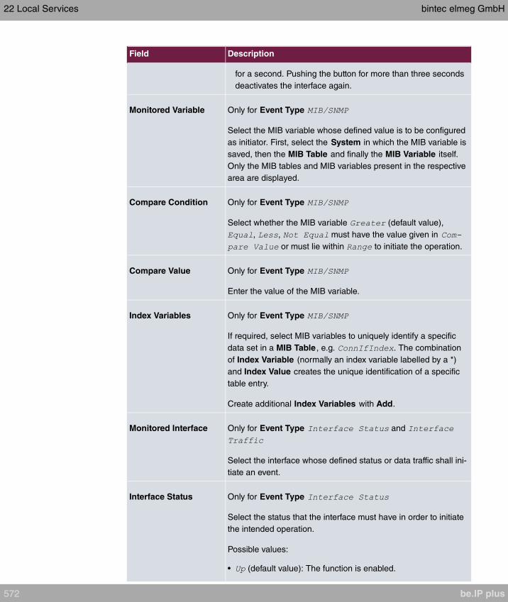
Field Description
for a second. Pushing the button for more than three seconds
deactivates the interface again.
Monitored Variable Only for Event Type
Select the MIB variable whose defined value is to be configured
as initiator. First, select the System in which the MIB variable is
saved, then the MIB Table and finally the MIB Variable itself.
Only the MIB tables and MIB variables present in the respective
area are displayed.
Compare Condition Only for Event Type
Select whether the MIB variable (default value),
, , must have the value given in
or must lie within to initiate the operation.
Compare Value Only for Event Type
Enter the value of the MIB variable.
Index Variables Only for Event Type
If required, select MIB variables to uniquely identify a specific
data set in a MIB Table , e.g. . The combination
of Index Variable (normally an index variable labelled by a *)
and Index Value creates the unique identification of a specific
table entry.
Create additional Index Variables with Add.
Monitored Interface Only for Event Type and
Select the interface whose defined status or data traffic shall ini-
tiate an event.
Interface Status Only for Event Type
Select the status that the interface must have in order to initiate
the intended operation.
Possible values:
• (default value): The function is enabled.
22 Local Services bintec elmeg GmbH
572 be.IP plus
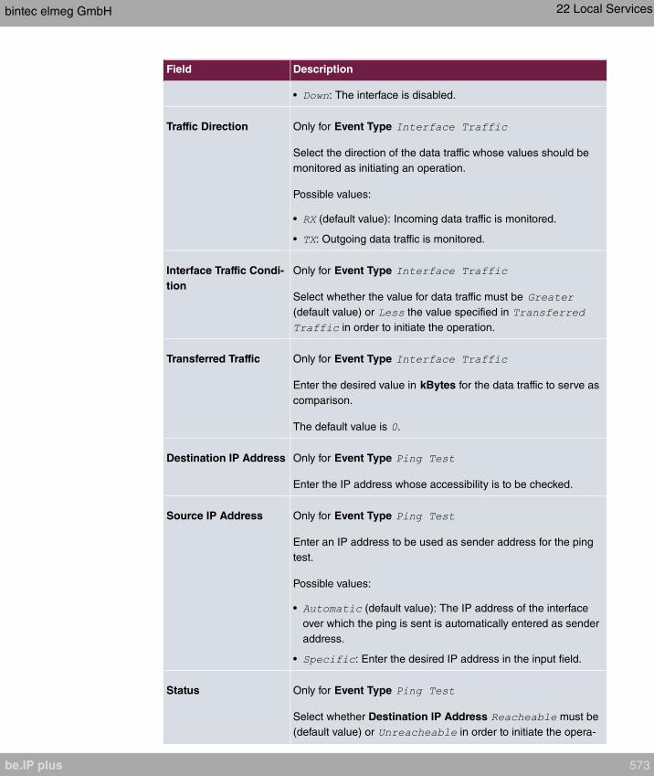
Field Description
• : The interface is disabled.
Traffic Direction Only for Event Type
Select the direction of the data traffic whose values should be
monitored as initiating an operation.
Possible values:
• (default value): Incoming data traffic is monitored.
• : Outgoing data traffic is monitored.
Interface Traffic Condi-
tion
Only for Event Type
Select whether the value for data traffic must be
(default value) or the value specified in
in order to initiate the operation.
Transferred Traffic Only for Event Type
Enter the desired value in kBytes for the data traffic to serve as
comparison.
The default value is .
Destination IP Address Only for Event Type
Enter the IP address whose accessibility is to be checked.
Source IP Address Only for Event Type
Enter an IP address to be used as sender address for the ping
test.
Possible values:
• (default value): The IP address of the interface
over which the ping is sent is automatically entered as sender
address.
• : Enter the desired IP address in the input field.
Status Only for Event Type
Select whether Destination IP Address must be
(default value) or in order to initiate the opera-
bintec elmeg GmbH 22 Local Services
be.IP plus 573
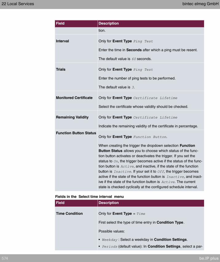
Field Description
tion.
Interval Only for Event Type
Enter the time in Seconds after which a ping must be resent.
The default value is seconds.
Trials Only for Event Type
Enter the number of ping tests to be performed.
The default value is .
Monitored Certificate Only for Event Type
Select the certificate whose validity should be checked.
Remaining Validity Only for Event Type
Indicate the remaining validity of the certificate in percentage.
Function Button StatusOnly for Event Type .
When creating the trigger the dropdown selection Function
Button Status allows you to choose which status of the func-
tion button activates or deactivates the trigger. If you set the
status to , the trigger becomes active if the status of the func-
tion button is , and inactive, if the state of the function
button is . If your set it to , the trigger becomes
active if the state of the function button is , and inact-
ive if the state of the function button is . The current
state is checked cyclically at the configured schedule interval.
Fields in the Select time interval menu
Field Description
Time Condition Only for Event Type =
First select the type of time entry in Condition Type.
Possible values:
• : Select a weekday in Condition Settings.
• (default value): In Condition Settings, select a par-
22 Local Services bintec elmeg GmbH
574 be.IP plus
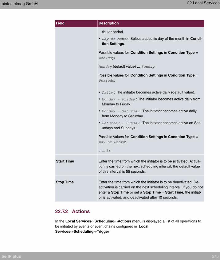
Field Description
ticular period.
• : Select a specific day of the month in Condi-
tion Settings.
Possible values for Condition Settings in Condition Type =
:
(default value) ... .
Possible values for Condition Settings in Condition Type =
:
• : The initiator becomes active daily (default value).
• : The initiator becomes active daily from
Monday to Friday.
• : The initiator becomes active daily
from Monday to Saturday.
• : The initiator becomes active on Sat-
urdays and Sundays.
Possible values for Condition Settings in Condition Type =
:
... .
Start Time Enter the time from which the initiator is to be activated. Activa-
tion is carried on the next scheduling interval. the default value
of this interval is 55 seconds.
Stop Time Enter the time from which the initiator is to be deactivated. De-
activation is carried on the next scheduling interval. If you do not
enter a Stop Time or set a Stop Time = Start Time, the initiat-
or is activated, and deactivated after 10 seconds.
22.7.2 Actions
In the Local Services->Scheduling->Actions menu is displayed a list of all operations to
be initiated by events or event chains configured in Local
Services->Scheduling->Trigger .
bintec elmeg GmbH 22 Local Services
be.IP plus 575

22.7.2.1 New
Choose the New button to configure additional operations.
The menu Local Services->Scheduling->Actions->New consists of the following fields:
Fields in the menu Basic Parameters
Field Description
DescriptionEnter your chosen designation for the action.
Command TypeSelect the desired action.
Possible values:
• (default value): Your device is rebooted.
• : The desired value is entered for a MIB variable.
• : The status of an interface is modified.
• : Only for devices with a wireless LAN. The
status of a WLAN-SSID is modified.
• : A software update is initiated.
• : A configuration file is loaded
onto your device or backed up by your device.
• : Accessibility of an IP address is checked.
• : A certificate is to be renewed,
deleted or entered.
• : Only for devices with a wireless
LAN. A scan of the 5 GHz frequency band is performed.
• : Only for devices with a wireless
LAN. A scan of the 5.8 GHz frequency range is performed.
• : Only for devices with a WLAN
controller. A Neighbor Scan is initiated by the WLAN network
controlled by the WLAN controller.
• : Only for devices with a WLAN controller.
The status of a wireless network is modified.
• : The operating mode of a WLAN
radio module is modified.
Event ListSelect the event list you want which has been created in Local
Services->Scheduling->Trigger .
22 Local Services bintec elmeg GmbH
576 be.IP plus
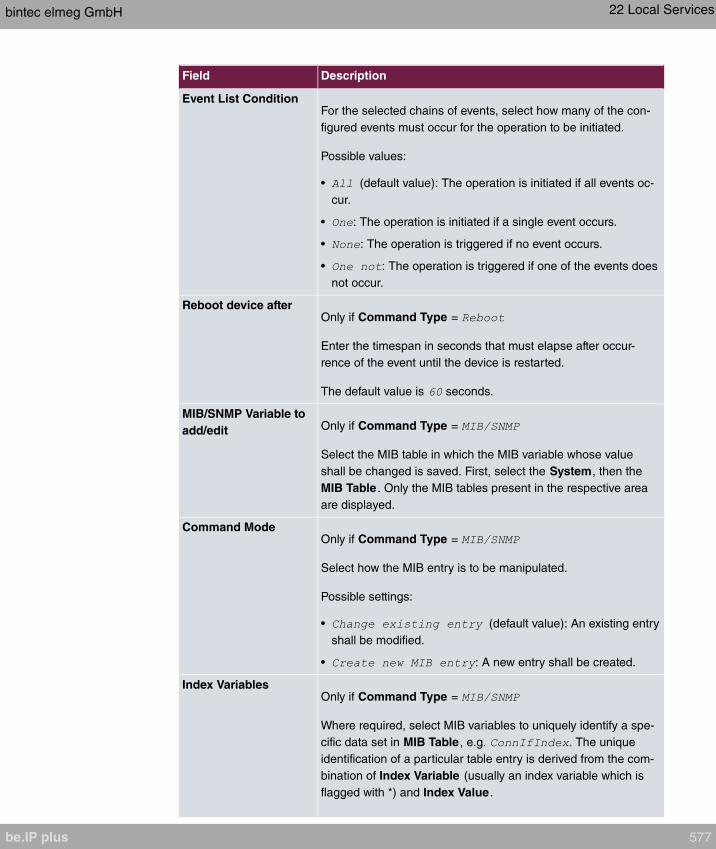
Field Description
Event List ConditionFor the selected chains of events, select how many of the con-
figured events must occur for the operation to be initiated.
Possible values:
• (default value): The operation is initiated if all events oc-
cur.
• : The operation is initiated if a single event occurs.
• : The operation is triggered if no event occurs.
• : The operation is triggered if one of the events does
not occur.
Reboot device afterOnly if Command Type =
Enter the timespan in seconds that must elapse after occur-
rence of the event until the device is restarted.
The default value is seconds.
MIB/SNMP Variable to
add/edit Only if Command Type =
Select the MIB table in which the MIB variable whose value
shall be changed is saved. First, select the System, then the
MIB Table . Only the MIB tables present in the respective area
are displayed.
Command ModeOnly if Command Type =
Select how the MIB entry is to be manipulated.
Possible settings:
• (default value): An existing entry
shall be modified.
• : A new entry shall be created.
Index VariablesOnly if Command Type =
Where required, select MIB variables to uniquely identify a spe-
cific data set in MIB Table , e.g. . The unique
identification of a particular table entry is derived from the com-
bination of Index Variable (usually an index variable which is
flagged with *) and Index Value.
bintec elmeg GmbH 22 Local Services
be.IP plus 577

Field Description
Use Index Variables to create more entries with Add.
Trigger StatusOnly if Command Type =
Select what status the event must have in order to modify the
MIB variable as defined.
Possible values:
• (default value): The value of the MIB variable is mod-
ified if the initiator is active.
• : The value of the MIB variable is modified if the ini-
tiator is inactive.
• : The value of the MIB variable is differentially modified if
the initiator status changes.
MIB VariablesOnly if Command Type =
Select the MIB variable whose value is to be configured as de-
pendent upon initiator status.
If the initiator is active (Trigger Status ), the MIB vari-
able is described with the value entered in Active Value .
If the initiator is inactive (Trigger Status ), the MIB
variable is described with the value entered in Inactive Value.
If the MIB variable is to be modified, depending on whether the
initiator is active or inactive (Trigger Status ), it is de-
scribed with an active initiator with the value entered in Active
Value and with an inactive initiator with the value in Inactive
Value.
Use Add to create more entries.
InterfaceOnly if Command Type =
Select the interface whose status should be changed.
Set interface statusOnly if Command Type =
Select the status to be set for the interface.
Possible values:
22 Local Services bintec elmeg GmbH
578 be.IP plus
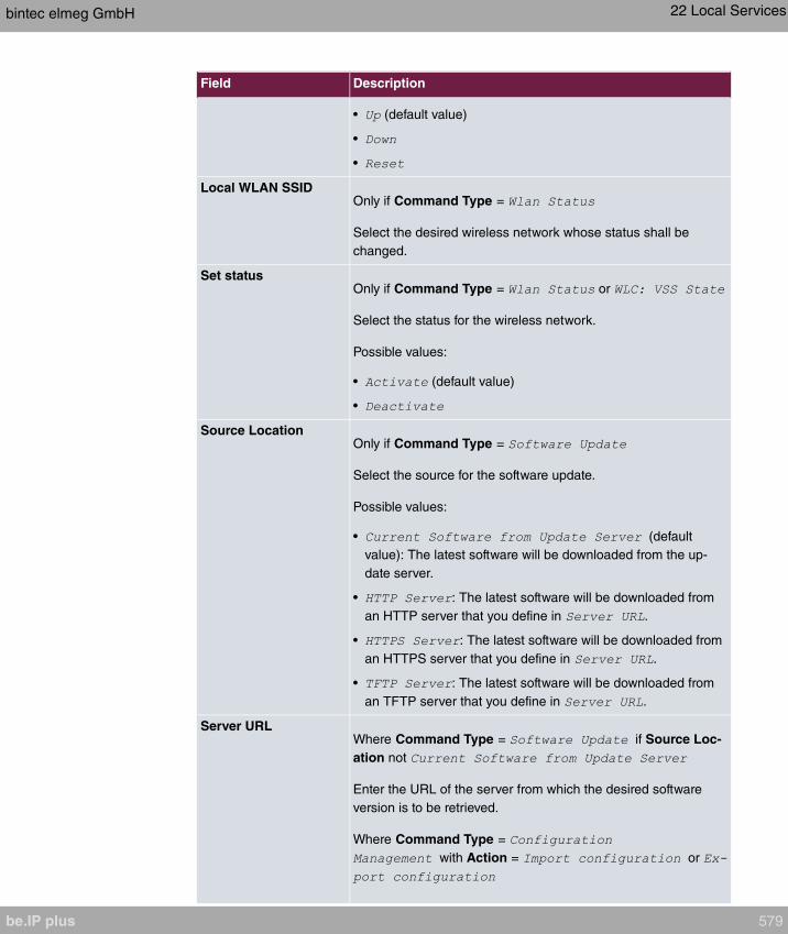
Field Description
• (default value)
•
•
Local WLAN SSIDOnly if Command Type =
Select the desired wireless network whose status shall be
changed.
Set statusOnly if Command Type = or
Select the status for the wireless network.
Possible values:
• (default value)
•
Source LocationOnly if Command Type =
Select the source for the software update.
Possible values:
• (default
value): The latest software will be downloaded from the up-
date server.
• : The latest software will be downloaded from
an HTTP server that you define in .
• : The latest software will be downloaded from
an HTTPS server that you define in .
• : The latest software will be downloaded from
an TFTP server that you define in .
Server URLWhere Command Type = if Source Loc-
ation not
Enter the URL of the server from which the desired software
version is to be retrieved.
Where Command Type =
with Action = or
bintec elmeg GmbH 22 Local Services
be.IP plus 579
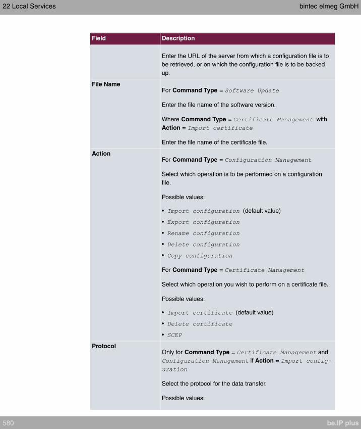
Field Description
Enter the URL of the server from which a configuration file is to
be retrieved, or on which the configuration file is to be backed
up.
File NameFor Command Type =
Enter the file name of the software version.
Where Command Type = with
Action =
Enter the file name of the certificate file.
ActionFor Command Type =
Select which operation is to be performed on a configuration
file.
Possible values:
• (default value)
•
•
•
•
For Command Type =
Select which operation you wish to perform on a certificate file.
Possible values:
• (default value)
•
•
ProtocolOnly for Command Type = and
if Action =
Select the protocol for the data transfer.
Possible values:
22 Local Services bintec elmeg GmbH
580 be.IP plus

Field Description
• (default value)
•
•
CSV File FormatOnly where Command Type =
and Action = or
Select whether the file is to be sent in the CSV format.
The CSV format can easily be read and modified. In addition,
you can view the corresponding file clearly using Microsoft Ex-
cel for example.
The function is enabled by default.
Remote File NameOnly if Command Type =
For Action =
Enter the name of the file under which it is saved on the server
from which it is to be retrieved.
For Action =
Enter the file name under which it should be saved on the serv-
er.
Local File NameOnly where Command Type =
and Action = ,
or
At import, renaming or copying enter a name for the configura-
tion file under which to save it locally on the device.
File Name in FlashWhere Command Type =
and Action =
Select the file to be exported.
Where Command Type =
and Action =
Select the file to be renamed.
bintec elmeg GmbH 22 Local Services
be.IP plus 581
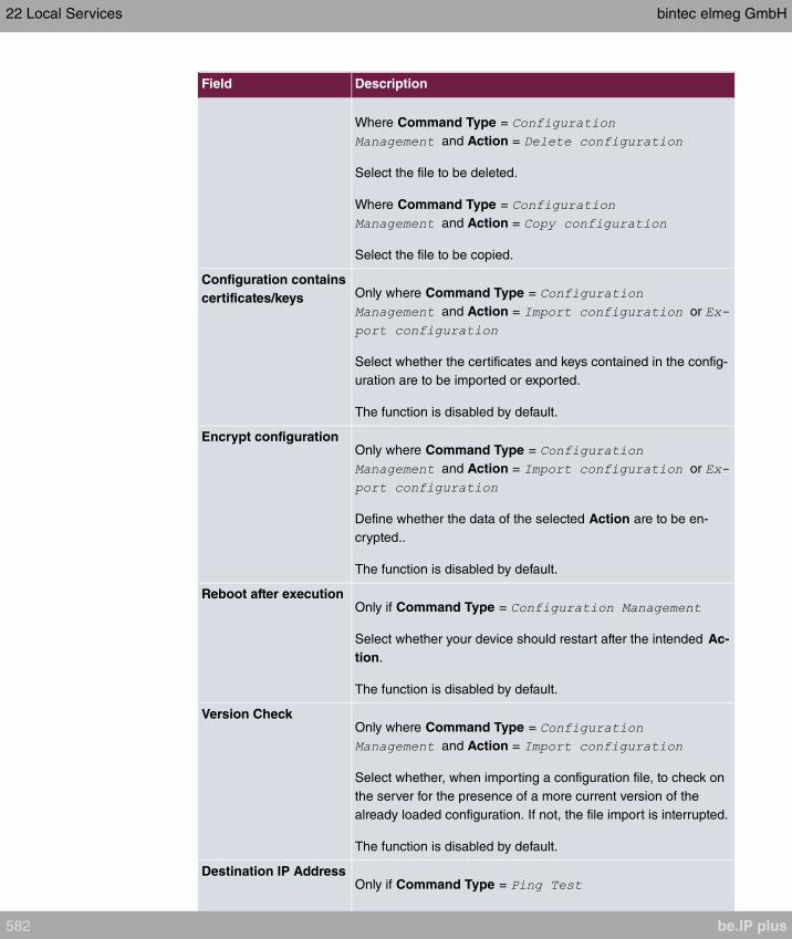
Field Description
Where Command Type =
and Action =
Select the file to be deleted.
Where Command Type =
and Action =
Select the file to be copied.
Configuration contains
certificates/keys Only where Command Type =
and Action = or
Select whether the certificates and keys contained in the config-
uration are to be imported or exported.
The function is disabled by default.
Encrypt configurationOnly where Command Type =
and Action = or
Define whether the data of the selected Action are to be en-
crypted..
The function is disabled by default.
Reboot after executionOnly if Command Type =
Select whether your device should restart after the intended Ac-
tion.
The function is disabled by default.
Version CheckOnly where Command Type =
and Action =
Select whether, when importing a configuration file, to check on
the server for the presence of a more current version of the
already loaded configuration. If not, the file import is interrupted.
The function is disabled by default.
Destination IP AddressOnly if Command Type =
22 Local Services bintec elmeg GmbH
582 be.IP plus
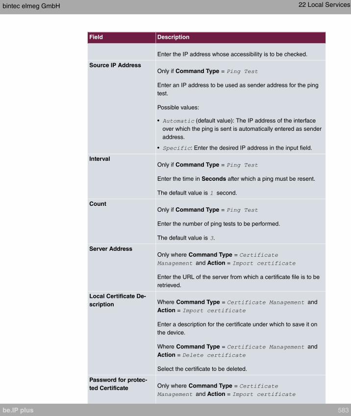
Field Description
Enter the IP address whose accessibility is to be checked.
Source IP AddressOnly if Command Type =
Enter an IP address to be used as sender address for the ping
test.
Possible values:
• (default value): The IP address of the interface
over which the ping is sent is automatically entered as sender
address.
• : Enter the desired IP address in the input field.
IntervalOnly if Command Type =
Enter the time in Seconds after which a ping must be resent.
The default value is second.
CountOnly if Command Type =
Enter the number of ping tests to be performed.
The default value is .
Server AddressOnly where Command Type =
and Action =
Enter the URL of the server from which a certificate file is to be
retrieved.
Local Certificate De-
scription Where Command Type = and
Action =
Enter a description for the certificate under which to save it on
the device.
Where Command Type = and
Action =
Select the certificate to be deleted.
Password for protec-
ted Certificate Only where Command Type =
and Action =
bintec elmeg GmbH 22 Local Services
be.IP plus 583

Field Description
Select whether to use a secure certificate requiring a password
and enter it into the entry field.
The function is disabled by default.
Overwrite similar certi-
ficate Only where Command Type =
and Action =
Select whether to overwrite a certificate already present on the
your device with the new one.
The function is disabled by default.
Write certificate in con-
figuration Only where Command Type =
and Action =
Select whether to integrate the certificate in a configuration file;
and if so, select the desired configuration file.
The function is disabled by default.
Certificate Request De-
scription Only where Command Type =
and Action =
Enter a description under which the SCEP certificate on your
device is to be saved.
URL SCEP Server URLOnly where Command Type =
and Action =
Enter the URL of the SCEP server, e.g.
Your CA administrator can provide you with the necessary data.
Subject NameOnly where Command Type =
and Action =
Enter a subject name with attributes.
Example:
CA NameOnly where Command Type =
and Action =
22 Local Services bintec elmeg GmbH
584 be.IP plus

Field Description
Enter the name of the CA certificate of the certification authority
(CA) from which you wish to request your certificate, e.g.
. Your CA administrator can provide you with the
necessary data.
PasswordOnly where Command Type =
and Action =
To obtain certificates, you may need a password from the certi-
fication authority. Enter the password you received from the cer-
tification authority here.
Key SizeOnly where Command Type =
and Action =
Select the length of the key to be created. Possible values are
(default value), and .
Autosave ModeOnly where Command Type =
and Action =
Select whether your device automatically stores the various
steps of the enrolment internally. This is an advantage if enrol-
ment cannot be concluded immediately. If the status has not
been saved, the incomplete registration cannot be completed.
As soon as the enrolment is completed and the certificate has
been downloaded from the CA server, it is automatically saved
in the device configuration.
The function is enabled by default.
Use CRLOnly where Command Type =
and Action =
Define the extent to which certificate revocation lists (CRLs) are
to be included in the validation of certificates issued by the own-
er of this certificate.
Possible values:
• (default value): In case there is an entry for a CDP,
CRL distribution point this should be evaluated in addition to
the CRLs globally configured in the device.
• : CRLs are always checked.
bintec elmeg GmbH 22 Local Services
be.IP plus 585

Field Description
• : No checking of CRLs.
Select radioOnly where Command Type = ,
or
Select the WLAN module on which to perform the frequency
band scan.
WLC SSIDOnly where Command Type =
Select the wireless network administered over the WLAN con-
troller whose status should be changed.
Operation Mode (Act-
ive) Only where Command Type =
Select the required operating mode for the selected radio mod-
ule if it currently has the status . You may select from
any of the operating modes that your device supports. So the
choice may vary from device to device.
Operation Mode (In-
active) Only where Command Type =
Select the required operating mode for the selected radio mod-
ule if it currently has the status . You may select from any
of the operating modes that your device supports. So the choice
may vary from device to device.
22.7.3 Options
You configure the schedule interval in the Local Services->Scheduling->Options menu.
The menu consists of the following fields:
Fields in the Scheduling Options menu
Field Description
Schedule Interval Select whether the schedule interval is to be enabled.
Enter the interval in seconds after which the system checks
whether events have occured.
Possible values are to .
22 Local Services bintec elmeg GmbH
586 be.IP plus
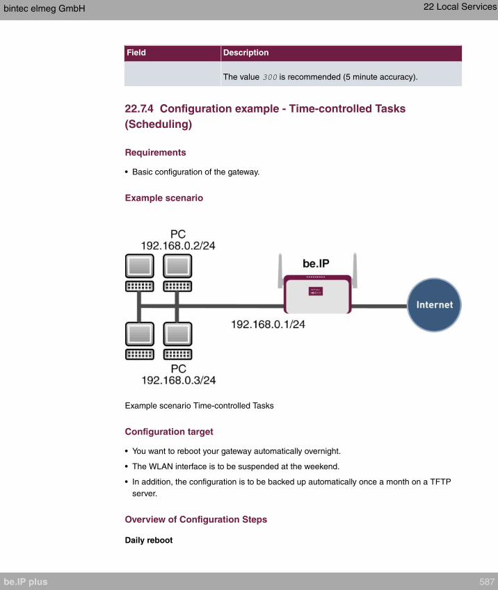
Field Description
The value is recommended (5 minute accuracy).
22.7.4 Configuration example - Time-controlled Tasks
(Scheduling)
Requirements
• Basic configuration of the gateway.
Example scenario
Example scenario Time-controlled Tasks
Configuration target
• You want to reboot your gateway automatically overnight.
• The WLAN interface is to be suspended at the weekend.
• In addition, the configuration is to be backed up automatically once a month on a TFTP
server.
Overview of Configuration Steps
Daily reboot
bintec elmeg GmbH 22 Local Services
be.IP plus 587
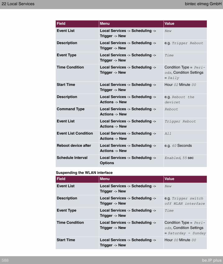
Field Menu Value
Event List Local Services -> Scheduling ->
Trigger -> New
Description Local Services -> Scheduling ->
Trigger -> New
e.g.
Event Type Local Services -> Scheduling ->
Trigger -> New
Time Condition Local Services -> Scheduling ->
Trigger -> New
Condition Type =
, Condition Settings
=
Start Time Local Services -> Scheduling ->
Trigger -> New
Hour Minute
Description Local Services -> Scheduling ->
Actions -> New
e.g.
Command Type Local Services -> Scheduling ->
Actions -> New
Event List Local Services -> Scheduling ->
Actions -> New
Event List Condition Local Services -> Scheduling ->
Actions -> New
Reboot device after Local Services -> Scheduling ->
Actions -> New
e.g. Seconds
Schedule Interval Local Services -> Scheduling ->
Options
, sec
Suspending the WLAN interface
Field Menu Value
Event List Local Services -> Scheduling ->
Trigger -> New
Description Local Services -> Scheduling ->
Trigger -> New
e.g.
Event Type Local Services -> Scheduling ->
Trigger -> New
Time Condition Local Services -> Scheduling ->
Trigger -> New
Condition Type =
, Condition Settings
=
Start Time Local Services -> Scheduling ->
Trigger -> New
Hour Minute
22 Local Services bintec elmeg GmbH
588 be.IP plus
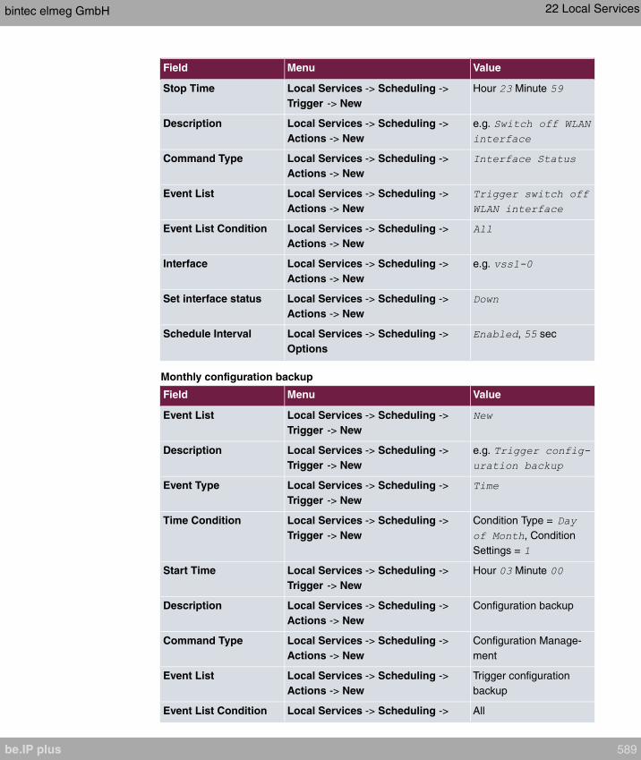
Field Menu Value
Stop Time Local Services -> Scheduling ->
Trigger -> New
Hour Minute
Description Local Services -> Scheduling ->
Actions -> New
e.g.
Command Type Local Services -> Scheduling ->
Actions -> New
Event List Local Services -> Scheduling ->
Actions -> New
Event List Condition Local Services -> Scheduling ->
Actions -> New
Interface Local Services -> Scheduling ->
Actions -> New
e.g.
Set interface status Local Services -> Scheduling ->
Actions -> New
Schedule Interval Local Services -> Scheduling ->
Options
, sec
Monthly configuration backup
Field Menu Value
Event List Local Services -> Scheduling ->
Trigger -> New
Description Local Services -> Scheduling ->
Trigger -> New
e.g.
Event Type Local Services -> Scheduling ->
Trigger -> New
Time Condition Local Services -> Scheduling ->
Trigger -> New
Condition Type =
, Condition
Settings =
Start Time Local Services -> Scheduling ->
Trigger -> New
Hour Minute
Description Local Services -> Scheduling ->
Actions -> New
Configuration backup
Command Type Local Services -> Scheduling ->
Actions -> New
Configuration Manage-
ment
Event List Local Services -> Scheduling ->
Actions -> New
Trigger configuration
backup
Event List Condition Local Services -> Scheduling -> All
bintec elmeg GmbH 22 Local Services
be.IP plus 589

Field Menu Value
Actions -> New
Action Local Services -> Scheduling ->
Actions -> New
Export configuration
Server URL Local Services -> Scheduling ->
Actions -> New
e.g.
CSV File Format Local Services -> Scheduling ->
Actions -> New
Remote File Name Local Services -> Scheduling ->
Actions -> New
e.g.
File Name in Flash Local Services -> Scheduling ->
Actions -> New
Configuration contains
certificates/keys
Local Services -> Scheduling ->
Actions -> New
Schedule Interval Local Services -> Scheduling ->
Options
, sec
22.8 Surveillance
In this menu, you can configure an automatic availability check for hosts or interfaces and
automatic ping tests.
You can monitor temperature with devices from the bintec WI series.
Note
This function cannot be configured on your device for connections that are authentic-
ated via a RADIUS server.
22.8.1 Hosts
A list of all monitored hosts is displayed in the Local Services->Surveillance->Hosts
menu.
22.8.1.1 Edit or New
Choose the icon to edit existing entries. Choose the New button to create additional
monitoring tasks.
22 Local Services bintec elmeg GmbH
590 be.IP plus
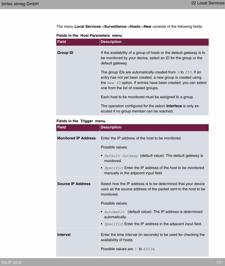
The menu Local Services->Surveillance->Hosts->New consists of the following fields:
Fields in the Host Parameters menu
Field Description
Group ID If the availability of a group of hosts or the default gateway is to
be monitored by your device, select an ID for the group or the
default gateway.
The group IDs are automatically created from to . If an
entry has not yet been created, a new group is created using
the option. If entries have been created, you can select
one from the list of created groups.
Each host to be monitored must be assigned to a group.
The operation configured for the select Interface is only ex-
ecuted if no group member can be reached.
Fields in the Trigger menu.
Field Description
Monitored IP Address Enter the IP address of the host to be monitored.
Possible values:
• (default value): The default gateway is
monitored.
• : Enter the IP address of the host to be monitored
manually in the adjacent input field.
Source IP Address Select how the IP address is to be determined that your device
uses as the source address of the packet sent to the host to be
monitored.
Possible values:
• (default value): The IP address is determined
automatically.
• : Enter the IP address in the adjacent input field.
Interval Enter the time interval (in seconds) to be used for checking the
availability of hosts.
Possible values are to .
bintec elmeg GmbH 22 Local Services
be.IP plus 591

Field Description
The default value is .
Within a group, the smallest Interval of the group members is
used.
Successful Trials Specify how many pings need to be answered for the host to be
regarded as accessible.
You can use this setting to specify, for example, when a host is
deemed to be accessible once more, and used again, instead of
a backup device.
Possible values are to .
The default value is .
Unsuccessful Trials Specify how many pings need to be unanswered for the host to
be regarded as inaccessible.
You can use this setting to specify, for example, when a host is
deemed to be inaccessible, and that a backup device should be
used.
Possible values are to .
The default value is .
Action to be performed Not for Action = .
Select which Action should be execude, when the Host is re-
garded as inaccessible. For most actions, you select an Inter-
face to which the Action relates.
All IP interfaces can be selected.
For each interface, select whether it is to be enabled ( ),
disabled ( default value), reset ( ), or the con-
nection restablished ( ).
The Actions and are also cancelled if the
hosts is regarded as accessible again.
With Action = you can monitor the IP address that is
specified under Monitored IP Address . This information can be
used for other functions, such as the Tracking IP Address
22 Local Services bintec elmeg GmbH
592 be.IP plus
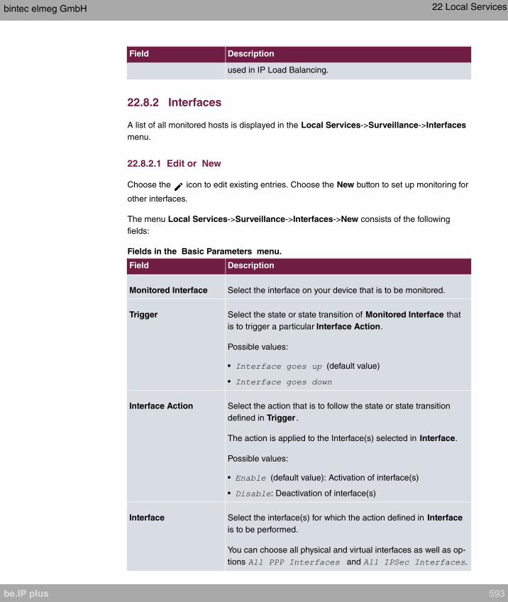
Field Description
used in IP Load Balancing.
22.8.2 Interfaces
A list of all monitored hosts is displayed in the Local Services->Surveillance->Interfaces
menu.
22.8.2.1 Edit or New
Choose the icon to edit existing entries. Choose the New button to set up monitoring for
other interfaces.
The menu Local Services->Surveillance->Interfaces->New consists of the following
fields:
Fields in the Basic Parameters menu.
Field Description
Monitored Interface Select the interface on your device that is to be monitored.
Trigger Select the state or state transition of Monitored Interface that
is to trigger a particular Interface Action.
Possible values:
• (default value)
•
Interface Action Select the action that is to follow the state or state transition
defined in Trigger .
The action is applied to the Interface(s) selected in Interface.
Possible values:
• (default value): Activation of interface(s)
• : Deactivation of interface(s)
Interface Select the interface(s) for which the action defined in Interface
is to be performed.
You can choose all physical and virtual interfaces as well as op-
tions and .
bintec elmeg GmbH 22 Local Services
be.IP plus 593
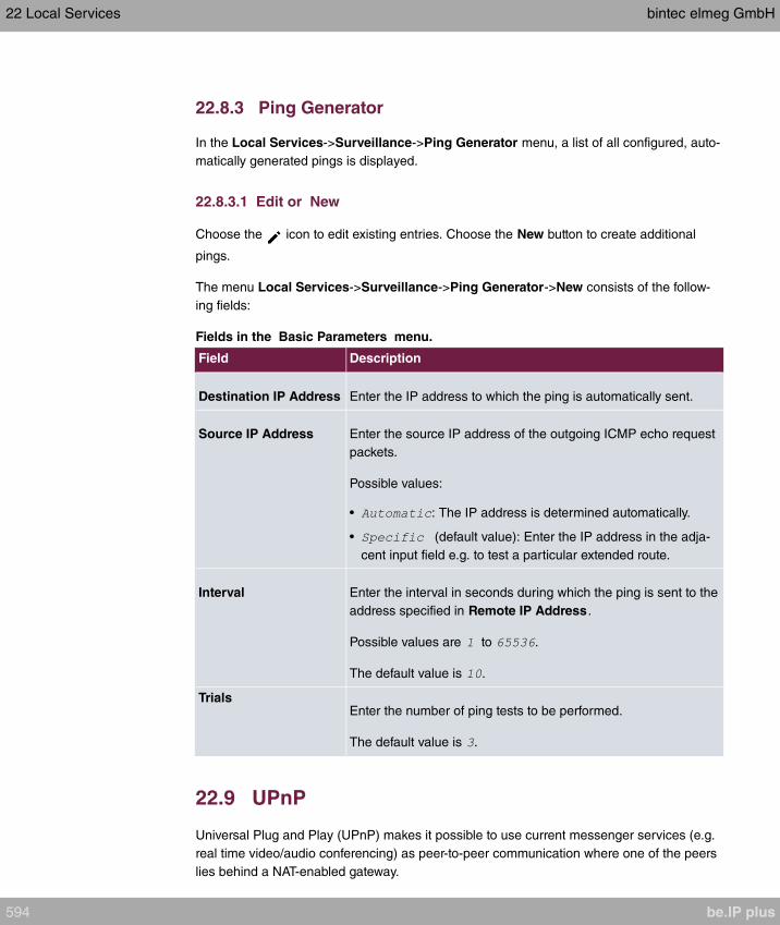
22.8.3 Ping Generator
In the Local Services->Surveillance->Ping Generator menu, a list of all configured, auto-
matically generated pings is displayed.
22.8.3.1 Edit or New
Choose the icon to edit existing entries. Choose the New button to create additional
pings.
The menu Local Services->Surveillance->Ping Generator->New consists of the follow-
ing fields:
Fields in the Basic Parameters menu.
Field Description
Destination IP Address Enter the IP address to which the ping is automatically sent.
Source IP Address Enter the source IP address of the outgoing ICMP echo request
packets.
Possible values:
• : The IP address is determined automatically.
• (default value): Enter the IP address in the adja-
cent input field e.g. to test a particular extended route.
Interval Enter the interval in seconds during which the ping is sent to the
address specified in Remote IP Address .
Possible values are to .
The default value is .
TrialsEnter the number of ping tests to be performed.
The default value is .
22.9 UPnP
Universal Plug and Play (UPnP) makes it possible to use current messenger services (e.g.
real time video/audio conferencing) as peer-to-peer communication where one of the peers
lies behind a NAT-enabled gateway.
22 Local Services bintec elmeg GmbH
594 be.IP plus
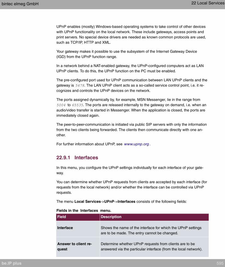
UPnP enables (mostly) Windows-based operating systems to take control of other devices
with UPnP functionality on the local network. These include gateways, access points and
print servers. No special device drivers are needed as known common protocols are used,
such as TCP/IP, HTTP and XML.
Your gateway makes it possible to use the subsystem of the Internet Gateway Device
(IGD) from the UPnP function range.
In a network behind a NAT-enabled gateway, the UPnP-configured computers act as LAN
UPnP clients. To do this, the UPnP function on the PC must be enabled.
The pre-configured port used for UPnP communication between LAN UPnP clients and the
gateway is . The LAN UPnP client acts as a so-called service control point, i.e. it re-
cognizes and controls the UPnP devices on the network.
The ports assigned dynamically by, for example, MSN Messenger, lie in the range from
to . The ports are released internally to the gateway on demand, i.e. when an
audio/video transfer is started in Messenger. When the application is closed, the ports are
immediately closed again.
The peer-to-peer-communication is initiated via public SIP servers with only the information
from the two clients being forwarded. The clients then communicate directly with one an-
other.
For further information about UPnP, see www.upnp.org .
22.9.1 Interfaces
In this menu, you configure the UPnP settings individually for each interface of your gate-
way.
You can determine whether UPnP requests from clients are accepted by each interface (for
requests from the local network) and/or whether the interface can be controlled via UPnP
requests.
The menu Local Services->UPnP->Interfaces consists of the following fields:
Fields in the Interfaces menu.
Field Description
Interface Shows the name of the interface for which the UPnP settings
are to be made. The entry cannot be changed.
Answer to client re-
quest
Determine whether UPnP requests from clients are to be
answered via the particular interface (from the local network).
bintec elmeg GmbH 22 Local Services
be.IP plus 595
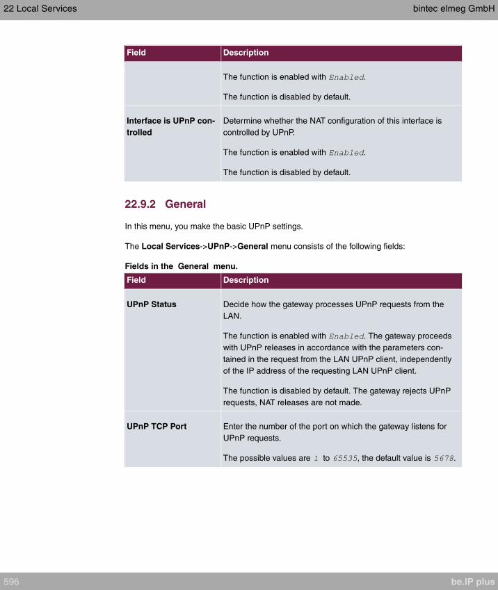
Field Description
The function is enabled with .
The function is disabled by default.
Interface is UPnP con-
trolled
Determine whether the NAT configuration of this interface is
controlled by UPnP.
The function is enabled with .
The function is disabled by default.
22.9.2 General
In this menu, you make the basic UPnP settings.
The Local Services->UPnP->General menu consists of the following fields:
Fields in the General menu.
Field Description
UPnP Status Decide how the gateway processes UPnP requests from the
LAN.
The function is enabled with . The gateway proceeds
with UPnP releases in accordance with the parameters con-
tained in the request from the LAN UPnP client, independently
of the IP address of the requesting LAN UPnP client.
The function is disabled by default. The gateway rejects UPnP
requests, NAT releases are not made.
UPnP TCP Port Enter the number of the port on which the gateway listens for
UPnP requests.
The possible values are to , the default value is .
22 Local Services bintec elmeg GmbH
596 be.IP plus
22.10 HotSpot Gateway
Important
The Hotspot Gateway must not be operated with IPv6 enabled, since IPv6 data traffic
is not registered by the Hotspot Gateway and, therefore, cannot be controlled.
The HotSpot Solution allows provision of public Internet accesses (using WLAN or wired
Ethernet). The solution is adapted to setup of smaller and larger Hotspot solutions for
cafes, hotels, companies, communal residences, campgrounds, etc.
The HotSpot Solution consists of a bintec elmegbintec elmeg gateway installed onsite
(with its own WLAN access point or additional connected WLAN device or wired LAN) and
of the Hotspot server, centrally located at a computing centre. The operator account is ad-
ministered on the server via an administration terminal (e.g., a hotel reception PC); this in-
cludes functions such as registration entry, generating tickets, statistical analysis, etc.
Login sequence at the Hotspot server
• When a new user connects with the Hotspot, he/she is automatically assigned an IP ad-
dress via DHCP.
• As soon as he attempts to access any Internet site with a browser, the user is redirected
to the home/login page.
• After the user has entered the registration data (user/password), these are sent to the
central RADIUS server (Hotspot server) as RADIUS registration.
• Following successful registration, the gateway opens Internet access.
• For each user, the gateway sends regular additional information to the RADIUS server
for recording accounting data.
• When the ticket expires, the user is automatically logged off and again redirected to the
home/login page.
Requirements
To operate a Hotspot, the customer requires:
• a bintec elmegbintec elmeg device as hotspot gateway with active Internet access and
configured hotspot server entries for login and accounting (see menu System Manage-
ment->Remote Authentication->RADIUS->New with Group Description
)
bintec elmeg GmbH 22 Local Services
be.IP plus 597
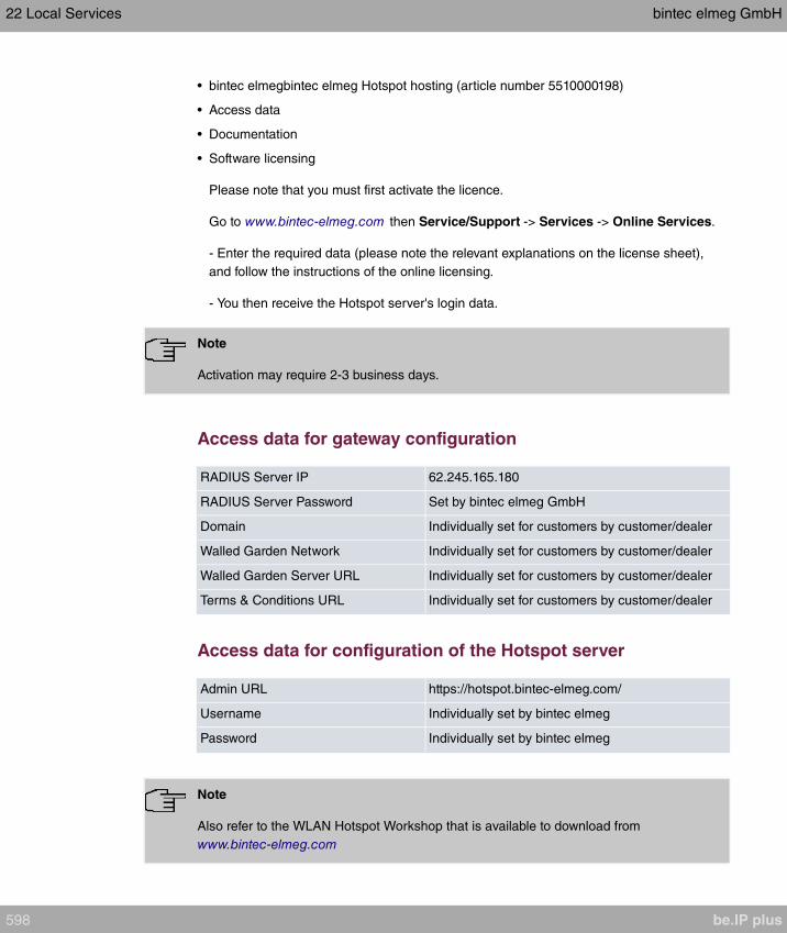
• bintec elmegbintec elmeg Hotspot hosting (article number 5510000198)
• Access data
• Documentation
• Software licensing
Please note that you must first activate the licence.
Go to www.bintec-elmeg.com then Service/Support -> Services -> Online Services.
- Enter the required data (please note the relevant explanations on the license sheet),
and follow the instructions of the online licensing.
- You then receive the Hotspot server's login data.
Note
Activation may require 2-3 business days.
Access data for gateway configuration
RADIUS Server IP 62.245.165.180
RADIUS Server Password Set by bintec elmeg GmbH
Domain Individually set for customers by customer/dealer
Walled Garden Network Individually set for customers by customer/dealer
Walled Garden Server URL Individually set for customers by customer/dealer
Terms & Conditions URL Individually set for customers by customer/dealer
Access data for configuration of the Hotspot server
Admin URL https://hotspot.bintec-elmeg.com/
Username Individually set by bintec elmeg
Password Individually set by bintec elmeg
Note
Also refer to the WLAN Hotspot Workshop that is available to download from
www.bintec-elmeg.com
22 Local Services bintec elmeg GmbH
598 be.IP plus

22.10.1 HotSpot Gateway
In the HotSpot Gateway menu, you can configure the bintec elmeg gateway installed
onsite for the Hotspot Solution.
A list of all configured hotspot networks is displayed in the Local Services->HotSpot
Gateway->HotSpot Gateway menu.
You can use the Enabled option to enable or disable the corresponding entry.
22.10.1.1 Edit or New
You configure the hotspot networks in the Local Services->HotSpot Gateway->HotSpot
Gateway-> menu. Choose the New button to set up additional Hotspot networks.
The Local Services->HotSpot Gateway->HotSpot Gateway-> menu consists of the
following fields:
Fields in the menu Basic Parameters
Field Description
InterfaceChoose the interface to which the Hotspot LAN or WLAN is con-
nected. When operating over LAN, enter the Ethernet interface
here (e. g. en1-0). If operating over WLAN, the WLAN interface
to which the access point is connected must be selected.
Caution
For security reasons you cannot configure your device over
an interface that is configured for the Hotspot. Therefore
take care when selecting the interface you want to use for
the Hotspot.
If you select the interface over which the current configura-
tion session is running, the current connection will be lost.
You must then log in again over a reachable interface that
is not configured for the Hotspot to configure your device.
Domain at the HotSpot
Server
Enter the domain name that you used when setting up the Hot-
Spot server for this customer. The domain name is required so
that the Hotspot server can distinguish between the different cli-
ents (customers).
bintec elmeg GmbH 22 Local Services
be.IP plus 599

Field Description
Walled GardenEnable this function if you want to define a limited and free area
of websites (intranet).
The function is not activated by default.
Walled Network / Net-
mask Only if Walled Garden is enabled.
Enter the network address of the Walled Network and the cor-
responding Netmask of the intranet server.
For the address range resulting from Walled Network / Net-
mask, clients require no authentication.
Example: Enter 192.168.0.0 / 255.255.255.0, if all IP addresses
from 192.168.0.0 to 19.168.0.255 are free. Enter 192.168.0.1 /
255.255.255.255, if only the IP address 192.168.0.1 is free.
Walled Garden URLOnly if Walled Garden is enabled.
Enter the Walled Garden URL of the intranet server. Freely ac-
cessible websites must be reachable over this address.
Terms &ConditionsOnly if Walled Garden is enabled.
In the Terms &Conditions input field, enter the address of the
general terms and conditions on the intranet server, or public
server, e.g., http://www.webserver.de/agb.htm. The page must
lie within the address range of the walled garden network.
Additional freely ac-
cessible Domain
Names
Only if Walled Garden is enabled.
Add further URLs or IP addresses with Add. The web pages
can be accessed via these additional freely accessible ad-
dresses.
Post Login URLHere you can specify the URL a user is redirected to after log-
ging in to the Hotspot Solution.
Language for login
window Here you can choose the language for the start/login page.
The following languages are supported: , ,
, , , and
.
22 Local Services bintec elmeg GmbH
600 be.IP plus
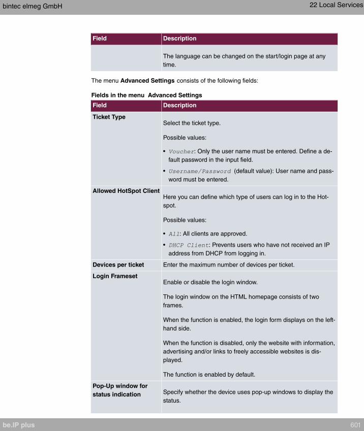
Field Description
The language can be changed on the start/login page at any
time.
The menu Advanced Settings consists of the following fields:
Fields in the menu Advanced Settings
Field Description
Ticket TypeSelect the ticket type.
Possible values:
• : Only the user name must be entered. Define a de-
fault password in the input field.
• (default value): User name and pass-
word must be entered.
Allowed HotSpot ClientHere you can define which type of users can log in to the Hot-
spot.
Possible values:
• : All clients are approved.
• : Prevents users who have not received an IP
address from DHCP from logging in.
Devices per ticket Enter the maximum number of devices per ticket.
Login FramesetEnable or disable the login window.
The login window on the HTML homepage consists of two
frames.
When the function is enabled, the login form displays on the left-
hand side.
When the function is disabled, only the website with information,
advertising and/or links to freely accessible websites is dis-
played.
The function is enabled by default.
Pop-Up window for
status indication Specify whether the device uses pop-up windows to display the
status.
bintec elmeg GmbH 22 Local Services
be.IP plus 601

Field Description
The function is enabled by default.
Default Idle TimeoutEnable or disable the Default Idle Timeout. If a hotspot user
does not trigger any data traffic for a configurable length of time,
they are logged out of the hotspot.
The function is enabled by default.
The default value is seconds.
22.10.2 Options
In the Local Services->HotSpot Gateway->Options menu, general settings are per-
formed for the hotspot.
The menu consists of the following fields:
Fields in the Basic Parameters menu.
Field Description
Host for multiple loca-
tions
If several locations (branches) are set up on the Hotspot server,
enter the value of the NAS identifier (RADIUS server parameter)
that has been registered for this location on the Hotspot server.
22.11 Wake-On-LAN
With the function Wake-On-LAN you can start network devices that are switched off via an
integrated network card. The network card also needs a power supply, even when the com-
puter is switched off. You can use filters and rule chains to define the conditions that need
to be met to send the so-called magic packet, and select the interfaces that are to be mon-
itored for the defined rule chains. Configuring the filters and rule chains is largely like con-
figuring filters and rule chains in the menu Access Rules.
22.11.1 Wake-On-LAN Filter
The menu Local Services->Wake-On-LAN->Wake-On-LAN Filter displays a list of all the
WOL filters that have been configured.
22 Local Services bintec elmeg GmbH
602 be.IP plus
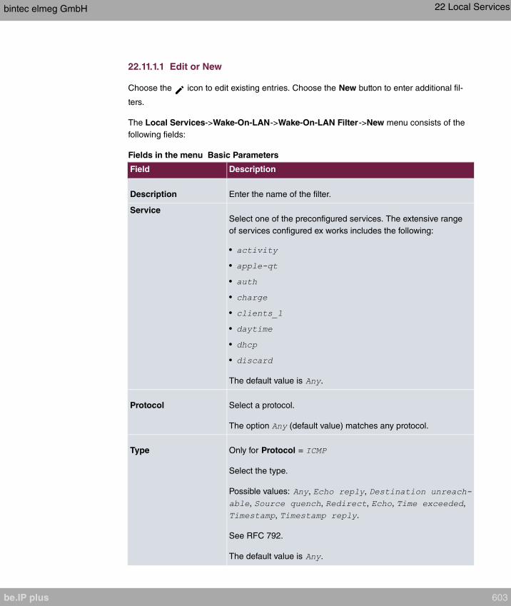
22.11.1.1 Edit or New
Choose the icon to edit existing entries. Choose the New button to enter additional fil-
ters.
The Local Services->Wake-On-LAN->Wake-On-LAN Filter ->New menu consists of the
following fields:
Fields in the menu Basic Parameters
Field Description
Description Enter the name of the filter.
ServiceSelect one of the preconfigured services. The extensive range
of services configured ex works includes the following:
•
•
•
•
•
•
•
•
The default value is .
Protocol Select a protocol.
The option (default value) matches any protocol.
Type Only for Protocol =
Select the type.
Possible values: , ,
, , , , ,
, .
See RFC 792.
The default value is .
bintec elmeg GmbH 22 Local Services
be.IP plus 603
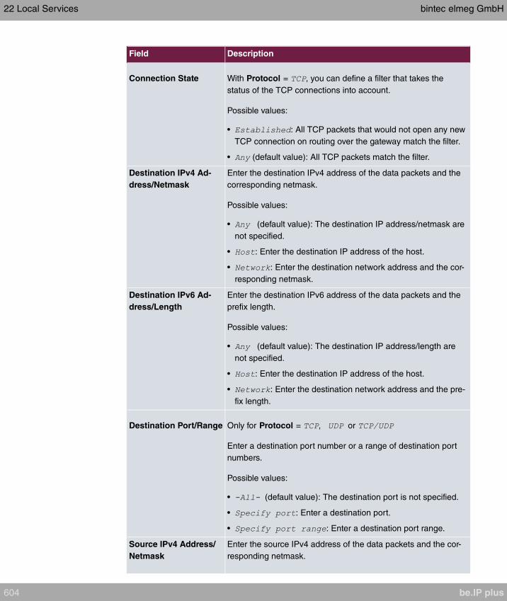
Field Description
Connection State With Protocol = , you can define a filter that takes the
status of the TCP connections into account.
Possible values:
• : All TCP packets that would not open any new
TCP connection on routing over the gateway match the filter.
• (default value): All TCP packets match the filter.
Destination IPv4 Ad-
dress/Netmask
Enter the destination IPv4 address of the data packets and the
corresponding netmask.
Possible values:
• (default value): The destination IP address/netmask are
not specified.
• : Enter the destination IP address of the host.
• : Enter the destination network address and the cor-
responding netmask.
Destination IPv6 Ad-
dress/Length
Enter the destination IPv6 address of the data packets and the
prefix length.
Possible values:
• (default value): The destination IP address/length are
not specified.
• : Enter the destination IP address of the host.
• : Enter the destination network address and the pre-
fix length.
Destination Port/Range Only for Protocol = , or
Enter a destination port number or a range of destination port
numbers.
Possible values:
• (default value): The destination port is not specified.
• : Enter a destination port.
• : Enter a destination port range.
Source IPv4 Address/
Netmask
Enter the source IPv4 address of the data packets and the cor-
responding netmask.
22 Local Services bintec elmeg GmbH
604 be.IP plus

Field Description
Possible values:
• (default value): The source IP address/netmask are not
specified.
• : Enter the source IP address of the host.
• : Enter the source network address and the corres-
ponding netmask.
Source IPv6 Address/
Length
Enter the source IPv6 address of the data packets and the pre-
fix length.
Possible values:
• (default value): The source IP address/length are not
specified.
• : Enter the source IP address of the host.
• : Enter the source network address and the prefix
length.
Source Port/Range Only for Protocol = , or
Enter a source port number or a range of source port numbers.
Possible values:
• (default value): The source port is not specified.
• : Enter a source port.
• : Enter a source port range.
DSCP/TOS Filter
(Layer 3)
Select the Type of Service (TOS).
Possible values:
• (default value): The type of service is ignored.
• : Differentiated Services Code Point
according to RFC 3260 is used to signal the priority of IP
packets (indicated in binary format, 6 bit).
• : Differentiated Services Code Point
according to RFC 3260 is used to signal the priority of IP
packets (indicated in decimal format).
• : Differentiated Services Code
Point according to RFC 3260 is used to signal the priority of
IP packets (indicated in hexadecimal format).
bintec elmeg GmbH 22 Local Services
be.IP plus 605
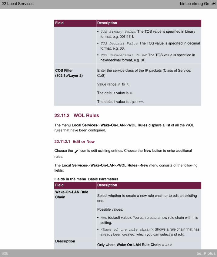
Field Description
• : The TOS value is specified in binary
format, e.g. 00111111.
• : The TOS value is specified in decimal
format, e.g. 63.
• : The TOS value is specified in
hexadecimal format, e.g. 3F.
COS Filter
(802.1p/Layer 2)
Enter the service class of the IP packets (Class of Service,
CoS).
Value range to .
The default value is .
The default value is .
22.11.2 WOL Rules
The menu Local Services->Wake-On-LAN->WOL Rules displays a list of all the WOL
rules that have been configured.
22.11.2.1 Edit or New
Choose the icon to edit existing entries. Choose the New button to enter additional
rules.
The Local Services->Wake-On-LAN->WOL Rules->New menu consists of the following
fields:
Fields in the menu Basic Parameters
Field Description
Wake-On-LAN Rule
Chain Select whether to create a new rule chain or to edit an existing
one.
Possible values:
• (default value): You can create a new rule chain with this
setting.
• : Shows a rule chain that has
already been created, which you can select and edit.
DescriptionOnly where Wake-On-LAN Rule Chain =
22 Local Services bintec elmeg GmbH
606 be.IP plus
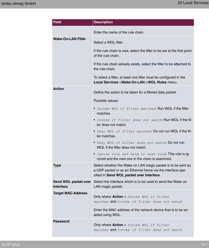
Field Description
Enter the name of the rule chain.
Wake-On-LAN FilterSelect a WOL filter.
If the rule chain is new, select the filter to be set at the first point
of the rule chain.
If the rule chain already exists, select the filter to be attached to
the rule chain.
To select a filter, at least one filter must be configured in the
Local Services->Wake-On-LAN->WOL Rules menu.
ActionDefine the action to be taken for a filtered data packet.
Possible values:
• : Run WOL if the filter
matches.
• : Run WOL if the fil-
ter does not match.
• : Do not run WOL if the fil-
ter matches.
• : Do not run
WOL if the filter does not match.
• : This rule is ig-
nored and the next one in the chain is examined.
Type Select whether the Wake on LAN magic packet is to be sent as
a UDP packet or as an Ethernet frame via the interface spe-
cified in Send WOL packet over Interface .
Send WOL packet over
Interface
Select the interface which is to be used to send the Wake on
LAN magic packet.
Target MAC-AddressOnly where Action =
and
Enter the MAC address of the network device that is to be en-
abled using WOL.
PasswordOnly where Action =
and
bintec elmeg GmbH 22 Local Services
be.IP plus 607

Field Description
If the network device that is to be enabled supports the "Se-
cureOn" function, enter the corresponding password for this
device here. The device is only enabled if the MAC address and
password are correct.
22.11.3 Interface Assignment
In this menu, the configured rule chains are assigned to individual interfaces which are then
monitored for these rule chains.
A list of all configured interface assignments is displayed in the Local Services->Wake-
On-LAN->Interface Assignment menu.
22.11.3.1 Edit or New
Choose the icon to edit existing entries. Choose the New button to create other entries.
The Local Services->Wake-On-LAN->Interface Assignment->New menu consists of the
following fields:
Fields in the menu Basic Parameters
Field Description
Interface Select the interface for which a configured rule chain is to be as-
signed.
Rule Chain Select a rule chain.
22.12 Trace Interface
The menu Trace Interface allows recording the data traffic of a specific interface and al-
lows you to save the recording as a PCAP file once the process has been stopped.
22 Local Services bintec elmeg GmbH
608 be.IP plus
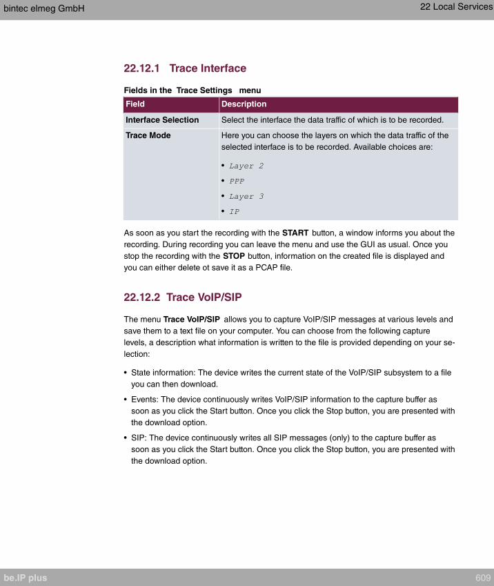
22.12.1 Trace Interface
Fields in the Trace Settings menu
Field Description
Interface Selection Select the interface the data traffic of which is to be recorded.
Trace Mode Here you can choose the layers on which the data traffic of the
selected interface is to be recorded. Available choices are:
•
•
•
•
As soon as you start the recording with the START button, a window informs you about the
recording. During recording you can leave the menu and use the GUI as usual. Once you
stop the recording with the STOP button, information on the created file is displayed and
you can either delete ot save it as a PCAP file.
22.12.2 Trace VoIP/SIP
The menu Trace VoIP/SIP allows you to capture VoIP/SIP messages at various levels and
save them to a text file on your computer. You can choose from the following capture
levels, a description what information is written to the file is provided depending on your se-
lection:
• State information: The device writes the current state of the VoIP/SIP subsystem to a file
you can then download.
• Events: The device continuously writes VoIP/SIP information to the capture buffer as
soon as you click the Start button. Once you click the Stop button, you are presented with
the download option.
• SIP: The device continuously writes all SIP messages (only) to the capture buffer as
soon as you click the Start button. Once you click the Stop button, you are presented with
the download option.
bintec elmeg GmbH 22 Local Services
be.IP plus 609

Chapter 23 Maintenance
This menu provides you with numerous functions for maintaining your device. It firstly
provides a menu for testing availability within the network. You can manage your system
configuration files. If more recent system software is available, you can use this menu to in-
stall it. If you need other languages for the configuration interface, you can import these.
You can also trigger a system reboot in this menu.
23.1 Log out Users
It can happen that an incompletely terminated configuration session affects functions of the
configuration interface. In this case, all active configurations can be checked and - if applic-
able - terminated.
23.1.1 Log out Users
In this menu, you are presented with a list of all active configuration sessions.
Fields in the manu Log out Users
Field Description
Class Dislays the class the signed-on user belongs to.
User Displays the user name.
Remote IP Address Displays the IP address from which the connection has been
established. This may be the address ofa PC, but it may also be
the address of an intermediate router.
Expires Displays when the connection will be automatically terminated
by the device.
Log out immediately If you activate the check box, this user will be disconnected
from the system when you click Logout.
23.1.1.1 Logout Options
After you have confirmed your selection of connections to be terminated with Logout you
can choose if any configuration related to the connections is to be saved before the user is
actually disconnected, and in which way.
23 Maintenance bintec elmeg GmbH
610 be.IP plus

23.2 Diagnostics
In the Maintenance->Diagnostics menu, you can test the availability of individual hosts,
the resolution of domain names and certain routes.
23.2.1 Ping Test
You can use the ping test to check whether a certain host in the LAN or an internet address
can be reached.
Fields in the Ping Test menu
Field Description
Test Ping Mode Select the IP version to be used for the ping test.
Possible values:
•
•
Test Ping Address Enter the IP address to be tested.
Use Interface Only for Test Ping Mode =
For link local addresses select the interface to be used for the
ping test. can be used for global addresses.
Pressing the Go button starts the ping test. The Output field displays the ping test mes-
sages.
23.2.2 DNS Test
The DNS test is used to check whether the domain name of a particular host is correctly re-
solved. The Output field displays the DSN test messages. The ping test is launched by en-
tering the domain name to be tested in DNS Address and clicking the Go button.
bintec elmeg GmbH 23 Maintenance
be.IP plus 611
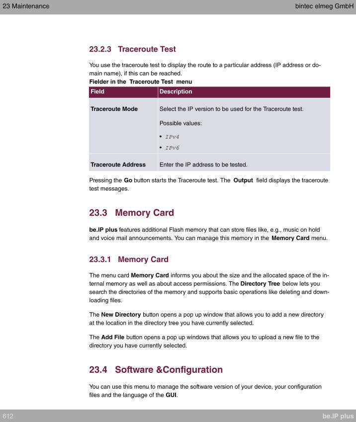
23.2.3 Traceroute Test
You use the traceroute test to display the route to a particular address (IP address or do-
main name), if this can be reached.
Fielder in the Traceroute Test menu
Field Description
Traceroute Mode Select the IP version to be used for the Traceroute test.
Possible values:
•
•
Traceroute Address Enter the IP address to be tested.
Pressing the Go button starts the Traceroute test. The Output field displays the traceroute
test messages.
23.3 Memory Card
be.IP plus features additional Flash memory that can store files like, e.g., music on hold
and voice mail announcements. You can manage this memory in the Memory Card menu.
23.3.1 Memory Card
The menu card Memory Card informs you about the size and the allocated space of the in-
ternal memory as well as about access permissions. The Directory Tree below lets you
search the directories of the memory and supports basic operations like deleting and down-
loading files.
The New Directory button opens a pop up window that allows you to add a new directory
at the location in the directory tree you have currently selected.
The Add File button opens a pop up windows that allows you to upload a new file to the
directory you have currently selected.
23.4 Software &Configuration
You can use this menu to manage the software version of your device, your configuration
files and the language of the GUI.
23 Maintenance bintec elmeg GmbH
612 be.IP plus
23.4.1 Options
Your device contains the version of the system software available at the time of production.
More recent versions may have since been released. You may therefore need to carry out
a software update.
Every new system software includes new features, better performance and any necessary
bugfixes from the previous version. You can find the current system software at
www.bintec-elmeg.com . The current documentation is also available here.
Important
If you want to update your software, make sure you consider the corresponding re-
lease notes. These describe the changes implemented in the new system software.
The result of an interrupted update (e.g. power failure during the update) could be that
your gateway no longer boots. Do not turn your device off during the update.
An update of BOOTmonitor and/or Logic is recommended in a few cases. In this case,
the release notes refer expressly to this fact. Only update BOOTmonitor or Logic if
bintec elmeg GmbH explicitly recommends this.
Flash
Your device saves its configuration in configuration files in the flash EEPROM (Electrically
Erasable Programmable Read Only Memory). The data even remains stored in the flash
when your device is switched off.
RAM
The current configuration and all changes you set on your device during operation are
stored in the working memory (RAM). The contents of the RAM are lost if the device is
switched off. So if you modify your configuration and want to keep these changes for the
next time you start your device, you must save the modified configuration in the flash
memory before switching off: The Save configuration button over the navigation area of
the GUI. This configuration is then saved in the flash in a file with the name . When
you start your device, the configuration file is used by default.
Actions
The files in the flash memory can be copied, moved, erased and newly created. It is also
possible to transfer configuration files between your device and a host via HTTP.
bintec elmeg GmbH 23 Maintenance
be.IP plus 613
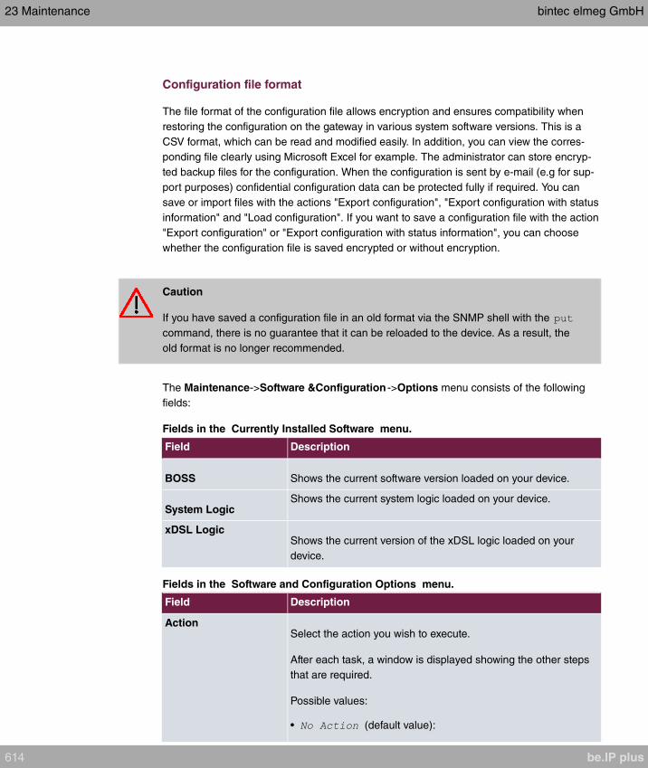
Configuration file format
The file format of the configuration file allows encryption and ensures compatibility when
restoring the configuration on the gateway in various system software versions. This is a
CSV format, which can be read and modified easily. In addition, you can view the corres-
ponding file clearly using Microsoft Excel for example. The administrator can store encryp-
ted backup files for the configuration. When the configuration is sent by e-mail (e.g for sup-
port purposes) confidential configuration data can be protected fully if required. You can
save or import files with the actions "Export configuration", "Export configuration with status
information" and "Load configuration". If you want to save a configuration file with the action
"Export configuration" or "Export configuration with status information", you can choose
whether the configuration file is saved encrypted or without encryption.
Caution
If you have saved a configuration file in an old format via the SNMP shell with the
command, there is no guarantee that it can be reloaded to the device. As a result, the
old format is no longer recommended.
The Maintenance->Software &Configuration ->Options menu consists of the following
fields:
Fields in the Currently Installed Software menu.
Field Description
BOSS Shows the current software version loaded on your device.
System LogicShows the current system logic loaded on your device.
xDSL LogicShows the current version of the xDSL logic loaded on your
device.
Fields in the Software and Configuration Options menu.
Field Description
ActionSelect the action you wish to execute.
After each task, a window is displayed showing the other steps
that are required.
Possible values:
• (default value):
23 Maintenance bintec elmeg GmbH
614 be.IP plus

Field Description
• : The configuration file Current
File Name in Flash is transferred to your local host. If you
click the Go button, a dialog box is displayed, in which you
can select the storage location on your PC and enter the de-
sired file name.
• : Under Filename select a config-
uration file you want to import. Please note: Click Go to first
load the file under the name in the flash memory for the
device. You must restart the device to enable it.
Please note: The files to be imported must be in CSV format!
• : The configuration file in the Source
File Name field is saved as Destination File Name.
• : The configuration in the Select
file field is deleted.
• : The configuration file in the Se-
lect file field is renamed to New File Name.
• : Only if, under Save
configuration with the setting
the current
configuration was saved as boot configuration and the previ-
ous boot configuration was also archived.
You can load back the archived boot configuration.
• : The file in the Select file
field is deleted.
• : You can import additional language ver-
sions of the GUI into your device. You can download the files
to your PC from the download area at
www.bintec-elmeg.com and from there import them to your
device
• : You can launch an update of
the system software, the xDSL logic and the BOOTmonitor.
• :
The active configuration from the RAM is transferred to your
local host. If you click the Go button, a dialog box is dis-
played, in which you can select the storage location on your
PC and enter the desired file name.
The following options require that an MMC/SD card is inserted
(if supported by your device) or that your device is equipped
bintec elmeg GmbH 23 Maintenance
be.IP plus 615
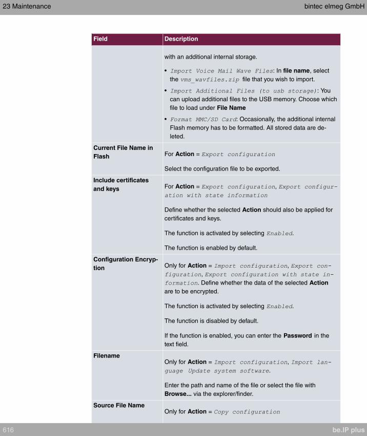
Field Description
with an additional internal storage.
• : In file name, select
the file that you wish to import.
• : You
can upload additional files to the USB memory. Choose which
file to load under File Name
• : Occasionally, the additional internal
Flash memory has to be formatted. All stored data are de-
leted.
Current File Name in
Flash For Action =
Select the configuration file to be exported.
Include certificates
and keys For Action = ,
Define whether the selected Action should also be applied for
certificates and keys.
The function is activated by selecting .
The function is enabled by default.
Configuration Encryp-
tion Only for Action = ,
,
. Define whether the data of the selected Action
are to be encrypted.
The function is activated by selecting .
The function is disabled by default.
If the function is enabled, you can enter the Password in the
text field.
FilenameOnly for Action = ,
.
Enter the path and name of the file or select the file with
Browse... via the explorer/finder.
Source File NameOnly for Action =
23 Maintenance bintec elmeg GmbH
616 be.IP plus

Field Description
Select the source file to be copied.
Destination File NameOnly for Action =
Enter the name of the copy.
Select fileOnly for Action = ,
or
Select the file or configuration to be renamed or deleted.
New File NameOnly for Action =
Enter the new name of the configuration file.
Source LocationOnly for Action =
Select the source of the update.
Possible values:
• (default value): The system software file is
stored locally on your PC.
• : The file is stored on a remote server specified
in the URL.
• : The file is on
the official update server.
URL Only for Source Location =
Enter the URL of the update server from which the system soft-
ware file is loaded.
In the Advanced Settings menu, the version of the currently installed system flash files will
be displayed.
23.5 Update System Phones
In the Maintenance->Update System Phones menu, you can update your system tele-
phone software.
bintec elmeg GmbH 23 Maintenance
be.IP plus 617

Note
Before beginning with the software update of your system telephone, you must load
the software in the Maintenance->Update System Phones->Firmware Files menu
on your SD card (if supported by you device) or in your system.
23.5.1 elmeg System Phones
In the Maintenance->Update System Phones->elmeg System Phones menu, you will
see a list of the connected elmeg system telephones. You can select telephones for imme-
diate updating of the software, or you can have the software updated on a scheduled basis.
In the case of immediate updating, there is no version control.
With time-controlled updating, a check is performed to determine whether a newer version
of the system software is saved on the SD card or in your system than on the telephone.
It's only in that case that an update takes place. The Update by time setting remains after
the update has been received, i.e. within the configured period a daily check is performed
to determine whether a newer version of the system software is available on the SD card or
in your system.
Values in the list elmeg System Phones
Field Description
Description Displays the description entered for the system telephone.
Phone Type Displays the system telephone type.
Serial Number Displays the system telephone serial number.
Systel Version Displays the system telephone software version.
Internal Storage Vers. Displays the inserted SD card version (if supported by you
device) or the version stored in internal storage.
Status/Update Status Displays the system telephone status, or a progress bar during
the update progress.
identifies a connected system telephone whose system soft-
ware is supported by your PABX.
identifies a system telephone that is either not connected, or
whose system software is not supported by your PABX.
23 Maintenance bintec elmeg GmbH
618 be.IP plus

Field Description
identifies an update currently not performed because the
maximum number of possible simultaneous updating processes
is momentarily exceeded. As soon as another updating process
is complete, the telephone is updated in the status.
For IP telephone, there is no restriction on simultaneous updat-
ing of system software.
With ISDN telephones, the number of simultaneous updates is
dependent on system upgrades. Per digital module, two tele-
phones can be simultaneously updated.
If the system telephone system software is not supported by
your PABX, there is still a way to update the system software.
During system software updating, you see a progress bar.
Update by time Displays whether, at a certain point, the system telephone soft-
ware should be updated.
This function is enabled on an individual device by setting a
checkmark. The function is disabled by default.
You can use the Select all and Deselect all buttons for all the
devices displayed.
Update immediately Displays whether the system telephone software should be up-
dated immediately.
This function is enabled on an individual device by setting a
checkmark. The function is disabled by default.
You can use the Select all and Deselect all buttons for all the
devices displayed.
23.5.2 elmeg OEM
In the Maintenance->Update System Phones->elmeg OEM menu, you will see a list of
the connected elmeg OEM telephones or base stations. This view displays both elmeg
IP1x telephones and elmeg DECT base stations, if there are any. You can select devices to
have their software updated immediately or allow them to download completely new soft-
ware from the system.
bintec elmeg GmbH 23 Maintenance
be.IP plus 619

In the case of immediate updating, there is no version control.
Note
Note that immediate software updates for DECT multi-cell systems are only available
via the system's web configurator and that they cannot be initiated by the PABX GUI.
Values in the list Update from internal Server
Field Description
Description Displays the description entered for the system telephone.
Phone Type Displays the system telephone type.
MAC Address Shows the system telephone's MAC address.
Phone Version Displays the software version of the telephone.
Internal Storage Vers. Displays the inserted SD card version (if supported by you
device) or the version stored in internal storage .
Status/Update Status Displays the system telephone status, or a progress bar during
the update progress.
identifies a connected system telephone whose system soft-
ware is supported by your PABX.
identifies a system telephone that is either not connected, or
whose system software is not supported by your PABX.
For IP telephone, there is no restriction on simultaneous updat-
ing of system software.
If the system telephone system software is not supported by
your PABX, there is still a way to update the system software.
During system software updating, you see a progress bar.
Update enabled Shows whether connected telephones can independently down-
load new software from the system.
You can select individual entries using the checkbox in the cor-
responding line, or select them all using the Select all button or
23 Maintenance bintec elmeg GmbH
620 be.IP plus
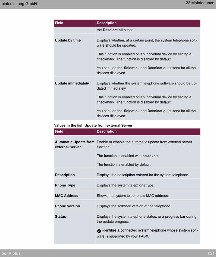
Field Description
the Deselect all button.
Update by time Displays whether, at a certain point, the system telephone soft-
ware should be updated.
This function is enabled on an individual device by setting a
checkmark. The function is disabled by default.
You can use the Select all and Deselect all buttons for all the
devices displayed.
Update immediately Displays whether the system telephone software should be up-
dated immediately.
This function is enabled on an individual device by setting a
checkmark. The function is disabled by default.
You can use the Select all and Deselect all buttons for all the
devices displayed.
Values in the list Update from external Server
Field Description
Automatic Update from
external Server
Enable or disable the automatic update from external server
function.
The function is enabled with .
The function is enabled by default.
Description Displays the description entered for the system telephone.
Phone Type Displays the system telephone type.
MAC Address Shows the system telephone's MAC address.
Phone Version Displays the software version of the telephone.
Status Displays the system telephone status, or a progress bar during
the update progress.
identifies a connected system telephone whose system soft-
ware is supported by your PABX.
bintec elmeg GmbH 23 Maintenance
be.IP plus 621
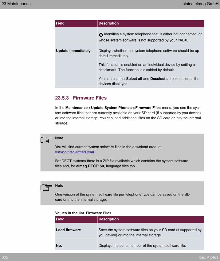
Field Description
identifies a system telephone that is either not connected, or
whose system software is not supported by your PABX.
Update immediately Displays whether the system telephone software should be up-
dated immediately.
This function is enabled on an individual device by setting a
checkmark. The function is disabled by default.
You can use the Select all and Deselect all buttons for all the
devices displayed.
23.5.3 Firmware Files
In the Maintenance->Update System Phones->Firmware Files menu, you see the sys-
tem software files that are currently available on your SD card (if supported by you device)
or into the internal storage. You can load additional files on the SD card or into the internal
storage.
Note
You will find current system software files in the download area, at
www.bintec-elmeg.com .
For DECT systems there is a ZIP file available which contains the system software
files and, for elmeg DECT150, language files too.
Note
One version of the system software file per telephone type can be saved on the SD
card or into the internal storage.
Values in the list Firmware Files
Field Description
Load firmware Save the system software files on your SD card (if supported by
you device) or into the internal storage.
No. Displays the serial number of the system software file.
23 Maintenance bintec elmeg GmbH
622 be.IP plus
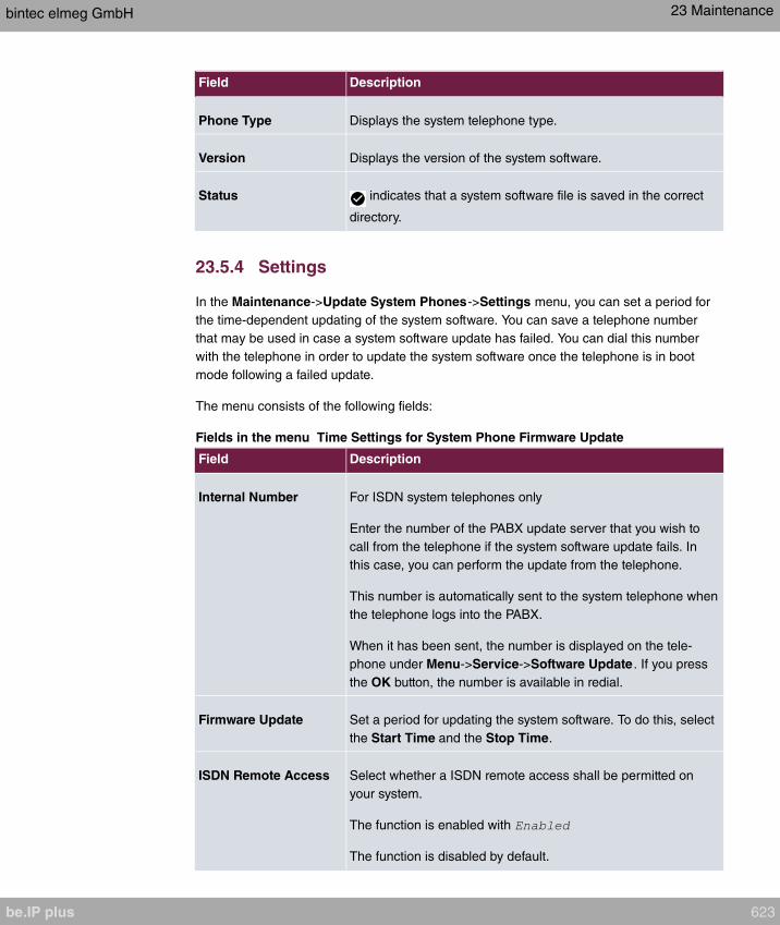
Field Description
Phone Type Displays the system telephone type.
Version Displays the version of the system software.
Status indicates that a system software file is saved in the correct
directory.
23.5.4 Settings
In the Maintenance->Update System Phones->Settings menu, you can set a period for
the time-dependent updating of the system software. You can save a telephone number
that may be used in case a system software update has failed. You can dial this number
with the telephone in order to update the system software once the telephone is in boot
mode following a failed update.
The menu consists of the following fields:
Fields in the menu Time Settings for System Phone Firmware Update
Field Description
Internal Number For ISDN system telephones only
Enter the number of the PABX update server that you wish to
call from the telephone if the system software update fails. In
this case, you can perform the update from the telephone.
This number is automatically sent to the system telephone when
the telephone logs into the PABX.
When it has been sent, the number is displayed on the tele-
phone under Menu->Service->Software Update . If you press
the OK button, the number is available in redial.
Firmware Update Set a period for updating the system software. To do this, select
the Start Time and the Stop Time.
ISDN Remote Access Select whether a ISDN remote access shall be permitted on
your system.
The function is enabled with
The function is disabled by default.
bintec elmeg GmbH 23 Maintenance
be.IP plus 623

23.6 Reboot
23.6.1 System Reboot
In this menu, you can trigger an immediate reboot of your device. Once your system has
restarted, you must call the GUI again and log in.
Pay attention to the LEDs on your device. For information on the meaning of the LEDs, see
the Technical Data chapter of the manual.
Note
Before a reboot, make sure you confirm your configuration changes by clicking the
Save configuration button, so that these are not lost when you reboot.
If you wish to restart your device, click the OK button. The device will reboot.
23.7 Factory Reset
In the menu Maintenance->Factory Reset, you can reset your device to the ex works
state without having to have physical access to it.
23 Maintenance bintec elmeg GmbH
624 be.IP plus

Chapter 24 External Reporting
In this system menu, you define what system protocol messages are saved on which com-
puters, and whether the system administrator should receive an e-mail for certain events.
Information on IP data traffic can also be saved--depending on the individual interfaces. In
addition, SNMP traps can be sent to specific hosts in case of error.
24.1 Syslog
Events in various subsystems of your device (e.g. PPP) are logged in the form of syslog
messages (system logging messages). The number of messages visible depends on the
level set (eight steps from over to ).
In addition to the data logged internally on your device, all information can and should be
transmitted to one or more external PCs for storage and processing, e.g. to the system ad-
ministrator’s PC. The syslog messages saved internally on your device are lost when you
reboot.
Warning
Make sure you only pass syslog messages to a safe computer. Check the data regu-
larly and ensure that there is always enough spare capacity available on the hard disk
of your PC.
Syslog Daemon
All Unix operating systems support the recording of syslog messages. For Windows PCs,
the Syslog Demon included in the DIME Tools can record the data and distribute to various
files depending on the contents (can be called in the download area at
www.bintec-elmeg.com ).
24.1.1 Syslog Servers
Configure your device as a syslog server so that defined system messages can be sent to
suitable hosts in the LAN.
In this menu, you define which messages are sent to which hosts and with which condi-
tions.
bintec elmeg GmbH 24 External Reporting
be.IP plus 625

A list of all configured system log servers displayed in the External
Reporting->Syslog->Syslog Servers menu.
24.1.1.1 New
Select the New button to set up additional syslog servers.
The menu External Reporting->Syslog->Syslog Servers->New consists of the following
fields:
Fields in the Basic Parameters menu.
Field Description
IP Address Enter the IP address of the host to which syslog messages are
passed.
Level Select the priority of the syslog messages that are to be sent to
the host.
Possible values:
• (highest priority)
•
•
•
•
•
• (default value)
• (lowest priority)
Syslog messages are only sent to the host if they have a higher
or identical priority to that indicated, i.e. at syslog level
all messages generated are forwarded to the host.
Facility Enter the syslog facility on the host.
This is only required if the Log Host is a Unix computer.
Possible values:
.
The default value is .
24 External Reporting bintec elmeg GmbH
626 be.IP plus
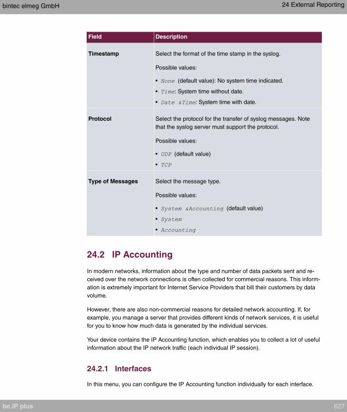
Field Description
Timestamp Select the format of the time stamp in the syslog.
Possible values:
• (default value): No system time indicated.
• : System time without date.
• : System time with date.
Protocol Select the protocol for the transfer of syslog messages. Note
that the syslog server must support the protocol.
Possible values:
• (default value)
•
Type of Messages Select the message type.
Possible values:
• (default value)
•
•
24.2 IP Accounting
In modern networks, information about the type and number of data packets sent and re-
ceived over the network connections is often collected for commercial reasons. This inform-
ation is extremely important for Internet Service Providers that bill their customers by data
volume.
However, there are also non-commercial reasons for detailed network accounting. If, for
example, you manage a server that provides different kinds of network services, it is useful
for you to know how much data is generated by the individual services.
Your device contains the IP Accounting function, which enables you to collect a lot of useful
information about the IP network traffic (each individual IP session).
24.2.1 Interfaces
In this menu, you can configure the IP Accounting function individually for each interface.
bintec elmeg GmbH 24 External Reporting
be.IP plus 627
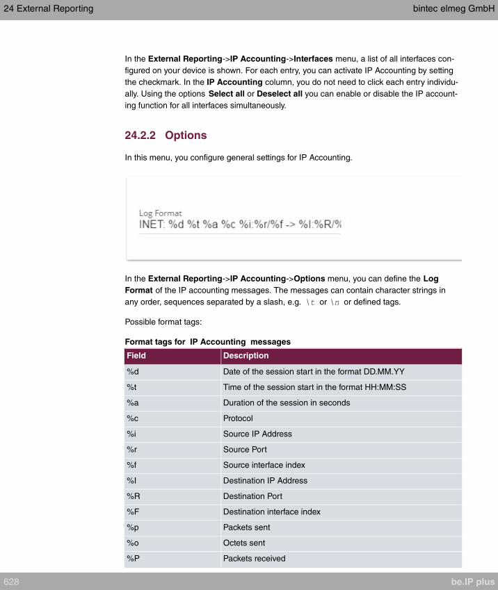
In the External Reporting->IP Accounting->Interfaces menu, a list of all interfaces con-
figured on your device is shown. For each entry, you can activate IP Accounting by setting
the checkmark. In the IP Accounting column, you do not need to click each entry individu-
ally. Using the options Select all or Deselect all you can enable or disable the IP account-
ing function for all interfaces simultaneously.
24.2.2 Options
In this menu, you configure general settings for IP Accounting.
In the External Reporting->IP Accounting->Options menu, you can define the Log
Format of the IP accounting messages. The messages can contain character strings in
any order, sequences separated by a slash, e.g. or or defined tags.
Possible format tags:
Format tags for IP Accounting messages
Field Description
%d Date of the session start in the format DD.MM.YY
%t Time of the session start in the format HH:MM:SS
%a Duration of the session in seconds
%c Protocol
%i Source IP Address
%r Source Port
%f Source interface index
%I Destination IP Address
%R Destination Port
%F Destination interface index
%p Packets sent
%o Octets sent
%P Packets received
24 External Reporting bintec elmeg GmbH
628 be.IP plus
Field Description
%O Octets received
%s Serial number for accounting message
%% %
By default, the following format instructions are entered in the Log Format field:
24.3 Alert Service
It was previously possible to send syslog messages from the router to any syslog host. De-
pending on the configuration, e-mail alerts are sent to the administrator as soon as relevant
syslog messages appear.
24.3.1 Alert Recipient
A list of Syslog messages is displayed in the Alert Recipient menu.
24.3.1.1 New
Select the New to create additional alert recipients.
The menu External Reporting->Alert Service->Alert Recipient->New consists of the fol-
lowing fields:
Fields in the Add / Edit Alert Recipient menu.
Field Description
Alert ServiceDisplays the alert service. You can select an alert service for
devices with UMTS.
Possible values:
• SMS
Recipient Enter the recipient's e-mail address. The entry is limited to 40
characters.
Message CompressionSelect whether the text in the alert E-mail is to be shortened.
The e-mail then contains the syslog message only once plus the
number of relevant events.
bintec elmeg GmbH 24 External Reporting
be.IP plus 629

Field Description
Enable or disable the field.
The function is enabled by default.
SubjectYou can enter a subject.
EventThis feature is available only for devices with Wireless LAN
Controller.
Select the event to trigger an email notification.
Possible values:
• (default value): A Syslog mes-
sage includes a specific string.
• : A new adjacent AP has been
found.
• : A new Rogue AP has been found,
i.e. an AP using an SSID of its own network, yet is not a com-
ponent of this network.
• : A new unconfigured AP has
reported to the WLAN.
• : A managed AP is no longer access-
ible.
Matching StringYou must enter a "Matching String". This must occur in a syslog
message as a necessary condition for triggering an alert.
The entry is limited to 55 characters. Bear in mind that without
the use of wildcards (e.g. "*"), only those strings that correspond
exactly to the entry fulfil the condition. The "Matching String"
entered therefore usually contains wildcards. To be informed of
all syslog messages of the selected level, just enter "*".
SeveritySelect the severity level which the string configured in the
Matching String field must reach to trigger an e-mail alert.
Possible values:
(default value), , , ,
, , ,
Monitored SubsystemsSelect the subsystems to be monitored.
24 External Reporting bintec elmeg GmbH
630 be.IP plus

Field Description
Add new subsystems with Add.
Message TimeoutEnter how long the router must wait after a relevant event be-
fore it is forced to send the alert mail.
Possible values are to . The value disables the
timeout. The default value is .
Number of MessagesEnter the number of syslog messages that must be reached be-
fore an E-mail can be sent for this case. If timeout is configured,
the mail is sent when this expires, even if the number of mes-
sages has not been reached.
Possible values are to ; the default value is .
24.3.2 Alert Settings
The menu External Reporting->Alert Service->Alert Settings consists of the following
fields:
Fields in the Basic Parameters menu.
Field Description
Alert ServiceSelect whether the alert service is to be enabled for the inter-
face.
The function is enabled with .
The function is enabled by default.
Maximum E-mails per
Minute Limit the number of outgoing mails per minute. Possible values
are to , the default value is .
Fields in the E-mail Parameters menu.
Field Description
Sender E-mail Address Enter the mail address to be entered in the sender field of the E-
mail.
SMTP ServerEnter the address (IP address or valid DNS name) of the mail
server to be used for sending the mails.
The entry is limited to 40 characters.
bintec elmeg GmbH 24 External Reporting
be.IP plus 631
Field Description
SMTP PortEncryption of e-mails (SSL / TLS).
The field SMTP Port is per default preset to and SSL En-
cryption is enabled.
SMTP AuthenticationAuthentication expected by the SMTP server.
Possible values:
• (default value): The server accepts and send emails
without further authentication.
• : The server only accepts e-mails if the router logs in
with the correct user name and password.
• : The server requires that e-mails are
called via POP3 by the sending IP with the correct POP3 user
name and password before sending an e-mail.
User NameOnly if SMTP Authentication = or
Enter the user name for the POP3 or SMTP server.
PasswordOnly if SMTP Authentication = or
Enter the password of this user.
POP3 ServerOnly if SMTP Authentication =
Enter the address of the server from which the e-mails are to be
retrieved.
POP3 TimeoutOnly if SMTP Authentication =
Enter how long the router must wait after the POP3 call before it
is forced to send the alert mail.
The default value is seconds.
Fields in the SMS Parameters menu (for devices with UMTS only)
Field Description
SMS Device You can receive notification of system alerts in text messages.
Select the device to be used to send the text message.
Maximum SMS per Day Limit the maximum number of SMS sent during a single day.
24 External Reporting bintec elmeg GmbH
632 be.IP plus

Field Description
Activating allows any number of SMS to be
sent.
The defualt value is 10 SMS per day.
Note: Entering a value of is equivalent to activating
.
24.4 SNMP
SNMP (Simple Network Management Protocol) is a protocol from the IP protocol family for
transporting management information about network components.
Every SNMP management system contains an MIB. SNMP can be used to configure, con-
trol and administrate various network components from one system. Such an SNMP tool is
included on your device: the Configuration Manager. As SNMP is a standard protocol, you
can use any other SNMP managers, e.g. HPOpenView.
For more information on the SNMP versions, see the relevant RFCs and drafts:
• SNMP V. 1: RFC 1157
• SNMP V. 2c: RFC 1901 - 1908
• SNMP V. 3: RFC 3410 - 3418
24.4.1 SNMP Trap Options
In the event of errors, a message - known as a trap packet - is sent unrequested to monitor
the system.
In the External Reporting->SNMP->SNMP Trap Options menu, you can configure the
sending of traps.
The menu consists of the following fields:
Fields in the Basic Parameters menu.
Field Description
SNMP Trap Broadcast-
ing
Select whether the transfer of SNMP traps is to be activated.
Your device then sends SNMP traps to the LAN's broadcast ad-
dress.
The function is activated by selecting .
bintec elmeg GmbH 24 External Reporting
be.IP plus 633
Field Description
The function is disabled by default.
SNMP Trap UDP Port Only if SNMP Trap Broadcasting is enabled.
Enter the number of the UDP port to which your device is to
send SNMP traps.
Any whole number is possible.
The default value is .
SNMP Trap Com-
munity
Only if SNMP Trap Broadcasting is enabled.
Enter a new SNMP code. This must be sent by the SNMP Man-
ager with every SNMP request so that this is accepted by your
device.
A character string of between and characters is pos-
sible.
The default value is .
24.4.2 SNMP Trap Hosts
In this menu, you specify the IP addresses to which your device is to send the SNMP traps.
In the External Reporting->SNMP->SNMP Trap Hosts menu, a list of all configured SN-
MP trap hosts is displayed.
24.4.2.1 New
Select the New button to create additional SNMP trap hosts.
The menu External Reporting->SNMP->SNMP Trap Hosts ->New consists of the follow-
ing fields:
Fields in the Basic Parameters menu.
Field Description
IP Address Enter the IP address of the SNMP trap host.
24.5 SIA
24 External Reporting bintec elmeg GmbH
634 be.IP plus

24.5.1 SIA
In the menu External Reporting->SIA->SIA, you can create and download a file that
provides extensive support information about the status of your device like, e.g., the current
configuration, available memory, uptime etc.
bintec elmeg GmbH 24 External Reporting
be.IP plus 635
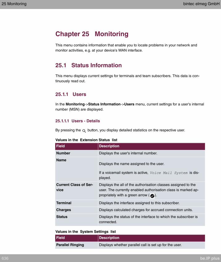
Chapter 25 Monitoring
This menu contains information that enable you to locate problems in your network and
monitor activities, e.g. at your device's WAN interface.
25.1 Status Information
This menu displays current settings for terminals and team subscribers. This data is con-
tinuously read out.
25.1.1 Users
In the Monitoring->Status Information->Users menu, current settings for a user's internal
number (MSN) are displayed.
25.1.1.1 Users - Details
By pressing the button, you display detailed statistics on the respective user.
Values in the Extension Status list
Field Description
Number Displays the user's internal number.
NameDisplays the name assigned to the user.
If a voicemail system is active, is dis-
played.
Current Class of Ser-
vice
Displays the all of the authorisation classes assigned to the
user. The currently enabled authorisation class is marked ap-
propriately with a green arrow ( ).
Terminal Displays the interface assigned to this subscriber.
Charges Displays calculated charges for accrued connection units.
Status Displays the status of the interface to which the subscriber is
connected.
Values in the System Settings list
Field Description
Parallel Ringing Displays whether parallel call is set up for the user.
25 Monitoring bintec elmeg GmbH
636 be.IP plus

Field Description
Call Forwarding Displays current call forwarding for this user.
Do not Disturb Displays whether call waiting protection is set up for the user.
(Only for system telephones)
Call Waiting Displays whether call waiting is allowed for internal and/or ex-
ternal calls.
Direct Call Displays whether direct call on receiver pickup is configured for
the user.
Room Monitoring Displays whether room monitoring is enabled for the user.
Receive Announce-
ment Calls
Displays whether the announcement is allowed for the user.
Receive Intercom Calls Displays whether simplex operation is allowed for the user.
Automatic Call Pick-up Displays whether automatic call acceptance is configured for
the user.
25.1.2 Teams
In the Monitoring->Status Information->Teams menu, current team settings are dis-
played.
25.1.2.1 Teams - Details
By pressing the button, you display detailed statistics for the respective team.
Values in the Team Status list
Field Description
Name Displays the name assigned to the team.
Number Displays the team's internal number.
Users assigned/Users
logged on
Displays the users assigned to the team, and how many of
these users are logged in.
Call Forwarding Displays current call forwarding for this team.
Values in the System Settings list
Field Description
Active Variant (Day) Displays the currently enabled call option for this team.
Switch call signalling Displays whether the call option can be switched manually, over
the calendar or manually and over the calendar.
Signalling Displays the type of call signalling in the team.
bintec elmeg GmbH 25 Monitoring
be.IP plus 637
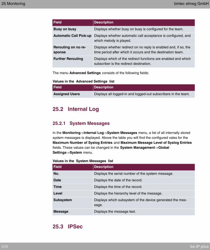
Field Description
Busy on busy Displays whether busy on busy is configured for the team.
Automatic Call Pick-up Displays whether automatic call acceptance is configured, and
which melody is played.
Rerouting on no re-
sponse
Displays whether redirect on no reply is enabled and, if so, the
time period after which it occurs and the destination team.
Further Rerouting Displays which of the redirect functions are enabled and which
subscriber is the redirect destination.
The menu Advanced Settings consists of the following fields:
Values in the Advanced Settings list
Field Description
Assigned Users Displays all logged-in and logged-out subscribers in the team.
25.2 Internal Log
25.2.1 System Messages
In the Monitoring->Internal Log->System Messages menu, a list of all internally stored
system messages is displayed. Above the table you will find the configured vales for the
Maximum Number of Syslog Entries and Maximum Message Level of Syslog Entries
fields. These values can be changed in the System Management->Global
Settings->System menu.
Values in the System Messages list
Field Description
No. Displays the serial number of the system message.
Date Displays the date of the record.
Time Displays the time of the record.
Level Displays the hierarchy level of the message.
Subsystem Displays which subsystem of the device generated the mes-
sage.
Message Displays the message text.
25.3 IPSec
25 Monitoring bintec elmeg GmbH
638 be.IP plus

25.3.1 IPSec Tunnels
A list of all configured IPSec tunnel providers is displayed in the
Monitoring->IPSec->IPSec Tunnels menu.
Values in the IPSec Tunnels list
Field Description
Description Displays the name of the IPSec tunnel.
Remote IP Displays the IP address of the remote IPSec Peers.
Remote Networks Displays the currently negotiated subnets of the remote termin-
al.
Security Algorithm Displays the encryption algorithm of the IPSec tunnel.
Status Displays the operating status of the IPSec tunnel.
Action Enables you to change the status of the IPSec tunnel as dis-
played.
Details Opens a detailed statistics window.
You change the status of the IPSec tunnel by clicking the button or the button in the
Action column.
By clicking the button, you display detailed statistics on the IPSec connection.
Values in the IPSec Tunnels list
Field Description
Description Shows the description of the peer.
Local IP Address Shows the WAN IP address of your device.
Remote IP Address Shows the WAN IP address of the connection partner.
Local ID Shows the ID of your device for this IPSec tunnel.
Remote ID Shows the ID of the peer.
Negotiation Type Shows the exchange type.
Authentication Method Shows the authentication method.
MTU Shows the current MTU (Maximum Transfer Unit).
Alive Check Shows the method for checking that the peer is reachable.
NAT Detection Displays the NAT detection method.
Local Port Shows the local port.
Remote Port Shows the remote port.
bintec elmeg GmbH 25 Monitoring
be.IP plus 639

Field Description
Packets Shows the total number of incoming and outgoing packets.
Bytes Shows the total number of incoming and outgoing bytes.
Errors Shows the total number of errors.
IKE (Phase-1) SAs (x)
Role / Algorithm / Life-
time remaining / Status
The parameters of the IKE (Phase 1) SAs are displayed here.
IPSec (Phase-2) SAs
(x)
Role / Algorithm / Life-
time remaining / Status
Shows the parameters of the IPSec (Phase 2) SAs.
Messages The system messages for this IPSec tunnel are displayed here.
25.3.2 IPSec Statistics
In the Monitoring->IPSec->IPSec Statistics menu, statistical values for all IPSec connec-
tions are displayed.
The menu consists of the following fields:
Fields in the Licences menu
Field Description
IPSec Tunnels Shows the IPSec licences currently in use (In Use) and the
maximum number of licenses usable (Maximum).
Fields in the Peers menu
Field Description
Status Displays the number of IPSec tunnels by their current status.
• Up: Currently active IPSec tunnels.
• Going up: IPSec tunnels currently in the tunnel setup phase.
• Blocked: IPSec tunnels that are blocked.
• Dormant: Currently inactive IPSec tunnels.
• Configured: Configured IPSec tunnels.
Fields in the SAs menu.
25 Monitoring bintec elmeg GmbH
640 be.IP plus

Field Description
IKE (Phase-1) Shows the number of active phase 1 SAs (Established) from
the total number of phase 1 SAs (Total).
IPSec (Phase-2) Shows the number of active phase 2 SAs (Established) from
the total number of phase 2 SAs (Total).
Fields in the Packet Statistics menu.
Field Description
Total Shows the number of all processed incoming (In) or outgoing
(Out) packets.
Passed Shows the number of incoming (In) or outgoing (Out) packets
forwarded in plain text.
Dropped Shows the number of all rejected incoming (In) or outgoing
(Out) packets.
Encrypted Shows the number of all incoming (In) or outgoing (Out) pack-
ets protected by IPSec.
Errors Shows the number of incoming (In) or outgoing (Out) packets
for which processing led to errors.
25.4 Interfaces
25.4.1 Statistics
In the Monitoring->Interfaces->Statistics menu, current values and activities of all device
interfaces are displayed.
With the filter bar, you can select whether to display Transfer Totals or Transfer
Throughput. The values per second are shown on the Transfer Throughput display.
Change the status of the interface by clicking the or the button in the Action column.
Values in the Statistics list
Field Description
No. Shows the serial number of the interface.
Description Displays the name of the interface.
Type Displays the interface text.
Tx Packets Shows the total number of packets sent.
Tx Bytes Displays the total number of octets sent.
bintec elmeg GmbH 25 Monitoring
be.IP plus 641

Field Description
Tx Errors Shows the total number of errors sent.
Rx Packets Shows the total number of packets received.
Rx Bytes Displays the total number of bytes received.
Rx Errors Shows the total number of errors received.
Status Shows the operating status of the selected interface.
Unchanged for Shows the length of time for which the operating status of the
interface has not changed.
Action Enables you to change the status of the interface as displayed.
Click the button to display the statistical data for the individual interfaces in detail.
Values in the Statistics list
Field Description
Description Displays the name of the interface.
MAC Address Displays the MAC address.
IP Address / Netmask Shows the IP address and the netmask.
NAT Indicates if NAT is activated for this interface.
Tx Packets Shows the total number of packets sent.
Tx Bytes Displays the total number of octets sent.
Rx Packets Shows the total number of packets received.
Rx Bytes Displays the total number of bytes received.
Fields in the TCP Connections menu
Field Description
Status Displays the status of an active TCP connection.
Local Address Displays the local IP address of the interface for an active TCP
connection.
Local Port Displays the local port of the IP address for an active TCP con-
nection.
Remote Address Displays the IP address to which an active TCP connection ex-
ists.
Remote Port Displays the port to which an active TCP connection exists.
25 Monitoring bintec elmeg GmbH
642 be.IP plus
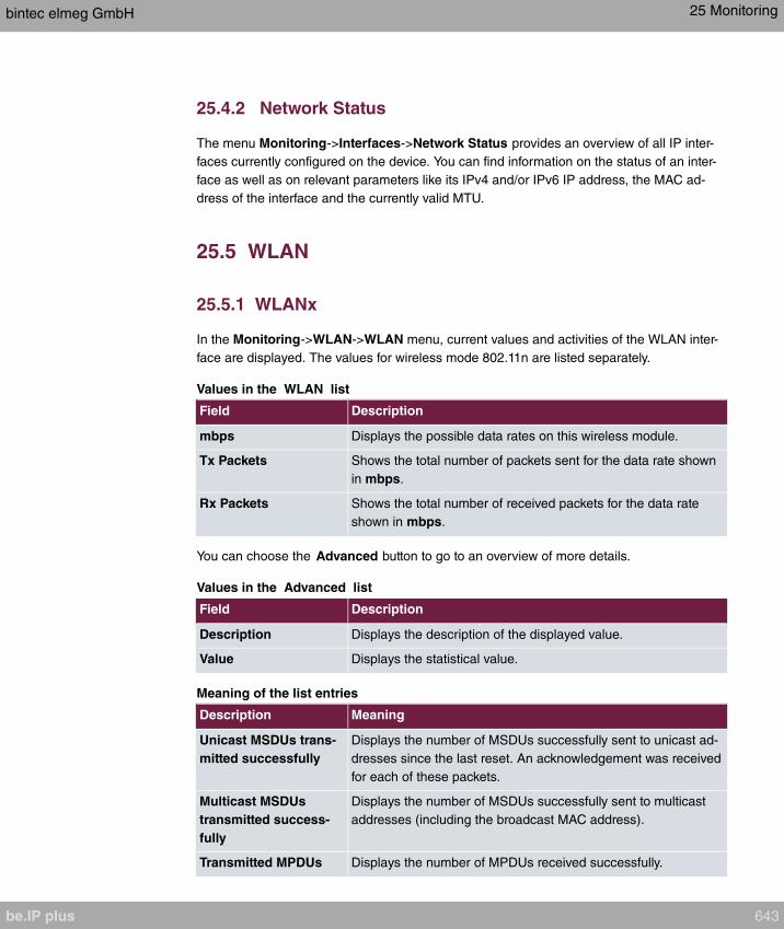
25.4.2 Network Status
The menu Monitoring->Interfaces->Network Status provides an overview of all IP inter-
faces currently configured on the device. You can find information on the status of an inter-
face as well as on relevant parameters like its IPv4 and/or IPv6 IP address, the MAC ad-
dress of the interface and the currently valid MTU.
25.5 WLAN
25.5.1 WLANx
In the Monitoring->WLAN->WLAN menu, current values and activities of the WLAN inter-
face are displayed. The values for wireless mode 802.11n are listed separately.
Values in the WLAN list
Field Description
mbps Displays the possible data rates on this wireless module.
Tx Packets Shows the total number of packets sent for the data rate shown
in mbps.
Rx Packets Shows the total number of received packets for the data rate
shown in mbps.
You can choose the Advanced button to go to an overview of more details.
Values in the Advanced list
Field Description
Description Displays the description of the displayed value.
Value Displays the statistical value.
Meaning of the list entries
Description Meaning
Unicast MSDUs trans-
mitted successfully
Displays the number of MSDUs successfully sent to unicast ad-
dresses since the last reset. An acknowledgement was received
for each of these packets.
Multicast MSDUs
transmitted success-
fully
Displays the number of MSDUs successfully sent to multicast
addresses (including the broadcast MAC address).
Transmitted MPDUs Displays the number of MPDUs received successfully.
bintec elmeg GmbH 25 Monitoring
be.IP plus 643
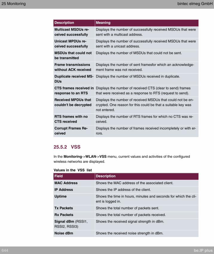
Description Meaning
Multicast MSDUs re-
ceived successfully
Displays the number of successfully received MSDUs that were
sent with a multicast address.
Unicast MPDUs re-
ceived successfully
Displays the number of successfully received MSDUs that were
sent with a unicast address.
MSDUs that could not
be transmitted
Displays the number of MSDUs that could not be sent.
Frame transmissions
without ACK received
Displays the number of sent framesfor which an acknowledge-
ment frame was not received.
Duplicate received MS-
DUs
Displays the number of MSDUs received in duplicate.
CTS frames received in
response to an RTS
Displays the number of received CTS (clear to send) frames
that were received as a response to RTS (request to send).
Received MPDUs that
couldn't be decrypted
Displays the number of received MSDUs that could not be en-
crypted. One reason for this could be that a suitable key was
not entered.
RTS frames with no
CTS received
Displays the number of RTS frames for which no CTS was re-
ceived.
Corrupt Frames Re-
ceived
Displays the number of frames received incompletely or with er-
rors.
25.5.2 VSS
In the Monitoring->WLAN->VSS menu, current values and activities of the configured
wireless networks are displayed.
Values in the VSS list
Field Description
MAC Address Shows the MAC address of the associated client.
IP Address Shows the IP address of the client.
Uptime Shows the time in hours, minutes and seconds for which the cli-
ent is logged in.
Tx Packets Shows the total number of packets sent.
Rx Packets Shows the total number of packets received.
Signal dBm (RSSI1,
RSSI2, RSSI3)
Shows the received signal strength in dBm.
Noise dBm Shows the received noise strength in dBm.
25 Monitoring bintec elmeg GmbH
644 be.IP plus

Field Description
Data Rate mbps Shows the current transmission rate of data received by this cli-
ent in mbps.
The following clock rates are possible: IEEE 802.11b: 11, 5.5, 2
and 1 mbps; IEEE 802.11g/a: 54, 48, 36, 24, 18, 12, 9, 6 mbps.
If the 5 GHz frequency band is used, the indication of 11, 5.5, 2
and 1 mbps is suppressed for IEEE 802.11b.
Rx Discards Displays the number of received data packets that have been
discarded if the bandwidth for receive traffic has been limited in
the Wireless LAN->WLAN->Wireless Networks (VSS)->
menu using the field Rx Shaping
Tx Discards Displays the number of data packets that were queued for
transmission and have been discarded if the bandwidth for
transmit traffic has been limited in the Wireless
LAN->WLAN->Wireless Networks (VSS)-> menu using the
field Rx Shaping.
VSS - Details for Connected Clients
In the Monitoring->WLAN->VSS-><Connected Client> -> menu, the current values
and activities of a connected client are shown. The values for wireless mode 802.11n are
listed separately.
Values in the list <Connected Client>
Field Description
Client MAC Address Shows the MAC address of the associated client.
IP Address Shows the IP address of the client.
Uptime Shows the time in hours, minutes and seconds for which the cli-
ent is logged in.
Signal dBm(RSSI1,
RSSI2, RSSI3)
Shows the received signal strength in dBm.
Noise dBm Shows the received noise strength in dBm.
SNR dB Signal-to-Noise Ratio in dB is an indicator of the quality of the
wireless connection.
Values:
• > 25 dB excellent
bintec elmeg GmbH 25 Monitoring
be.IP plus 645
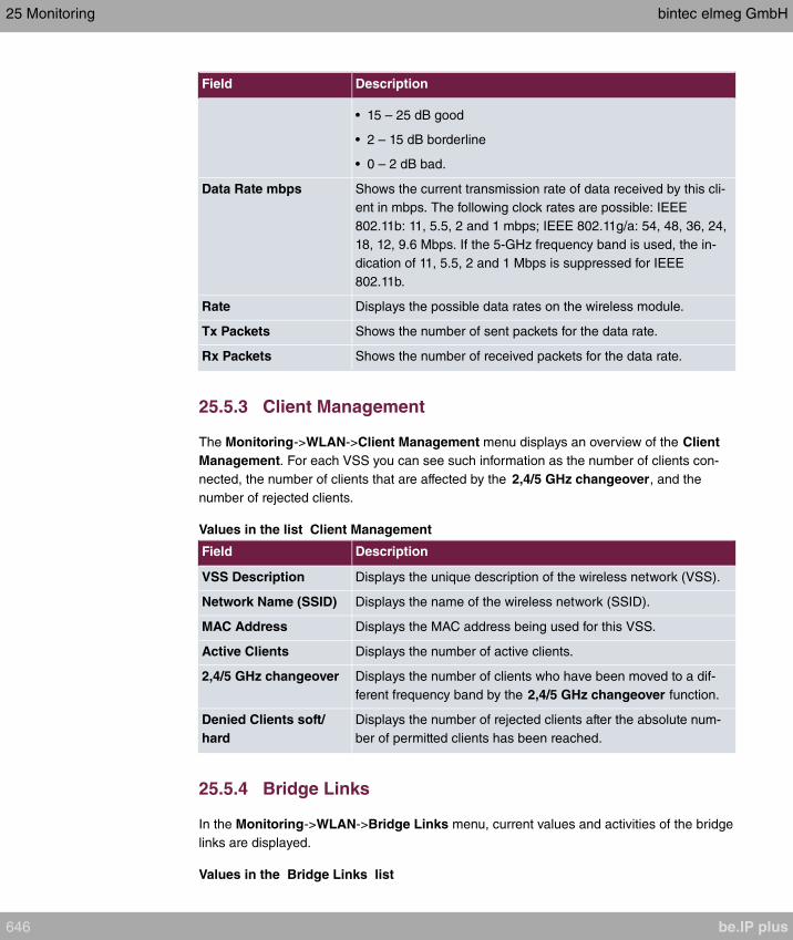
Field Description
• 15 – 25 dB good
• 2 – 15 dB borderline
• 0 – 2 dB bad.
Data Rate mbps Shows the current transmission rate of data received by this cli-
ent in mbps. The following clock rates are possible: IEEE
802.11b: 11, 5.5, 2 and 1 mbps; IEEE 802.11g/a: 54, 48, 36, 24,
18, 12, 9.6 Mbps. If the 5-GHz frequency band is used, the in-
dication of 11, 5.5, 2 and 1 Mbps is suppressed for IEEE
802.11b.
Rate Displays the possible data rates on the wireless module.
Tx Packets Shows the number of sent packets for the data rate.
Rx Packets Shows the number of received packets for the data rate.
25.5.3 Client Management
The Monitoring->WLAN->Client Management menu displays an overview of the Client
Management. For each VSS you can see such information as the number of clients con-
nected, the number of clients that are affected by the 2,4/5 GHz changeover, and the
number of rejected clients.
Values in the list Client Management
Field Description
VSS Description Displays the unique description of the wireless network (VSS).
Network Name (SSID) Displays the name of the wireless network (SSID).
MAC Address Displays the MAC address being used for this VSS.
Active Clients Displays the number of active clients.
2,4/5 GHz changeover Displays the number of clients who have been moved to a dif-
ferent frequency band by the 2,4/5 GHz changeover function.
Denied Clients soft/
hard
Displays the number of rejected clients after the absolute num-
ber of permitted clients has been reached.
25.5.4 Bridge Links
In the Monitoring->WLAN->Bridge Links menu, current values and activities of the bridge
links are displayed.
Values in the Bridge Links list
25 Monitoring bintec elmeg GmbH
646 be.IP plus
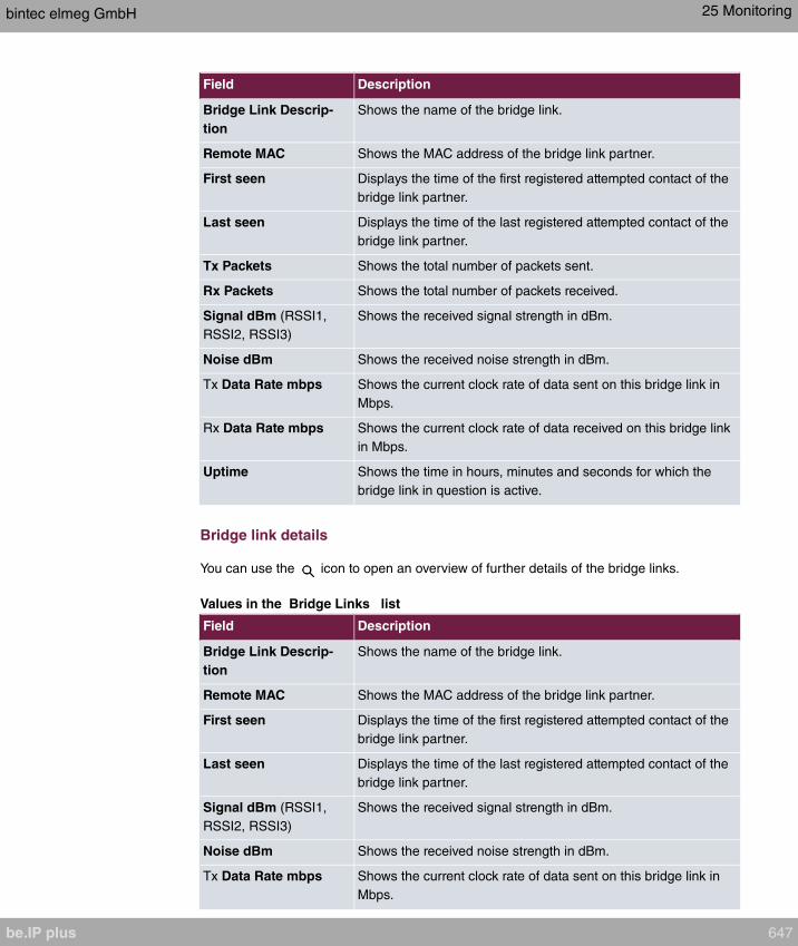
Field Description
Bridge Link Descrip-
tion
Shows the name of the bridge link.
Remote MAC Shows the MAC address of the bridge link partner.
First seen Displays the time of the first registered attempted contact of the
bridge link partner.
Last seen Displays the time of the last registered attempted contact of the
bridge link partner.
Tx Packets Shows the total number of packets sent.
Rx Packets Shows the total number of packets received.
Signal dBm (RSSI1,
RSSI2, RSSI3)
Shows the received signal strength in dBm.
Noise dBm Shows the received noise strength in dBm.
Tx Data Rate mbps Shows the current clock rate of data sent on this bridge link in
Mbps.
Rx Data Rate mbps Shows the current clock rate of data received on this bridge link
in Mbps.
Uptime Shows the time in hours, minutes and seconds for which the
bridge link in question is active.
Bridge link details
You can use the icon to open an overview of further details of the bridge links.
Values in the Bridge Links list
Field Description
Bridge Link Descrip-
tion
Shows the name of the bridge link.
Remote MAC Shows the MAC address of the bridge link partner.
First seen Displays the time of the first registered attempted contact of the
bridge link partner.
Last seen Displays the time of the last registered attempted contact of the
bridge link partner.
Signal dBm (RSSI1,
RSSI2, RSSI3)
Shows the received signal strength in dBm.
Noise dBm Shows the received noise strength in dBm.
Tx Data Rate mbps Shows the current clock rate of data sent on this bridge link in
Mbps.
bintec elmeg GmbH 25 Monitoring
be.IP plus 647
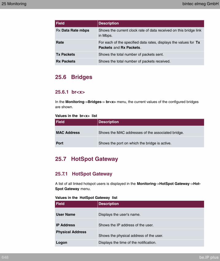
Field Description
Rx Data Rate mbps Shows the current clock rate of data received on this bridge link
in Mbps.
Rate For each of the specified data rates, displays the values for Tx
Packets and Rx Packets.
Tx Packets Shows the total number of packets sent.
Rx Packets Shows the total number of packets received.
25.6 Bridges
25.6.1 br<x>
In the Monitoring->Bridges-> br<x> menu, the current values of the configured bridges
are shown.
Values in the br<x> list
Field Description
MAC Address Shows the MAC addresses of the associated bridge.
Port Shows the port on which the bridge is active.
25.7 HotSpot Gateway
25.7.1 HotSpot Gateway
A list of all linked hotspot users is displayed in the Monitoring->HotSpot Gateway->Hot-
Spot Gateway menu.
Values in the HotSpot Gateway list
Field Description
User Name Displays the user's name.
IP Address Shows the IP address of the user.
Physical AddressShows the physical address of the user.
Logon Displays the time of the notification.
25 Monitoring bintec elmeg GmbH
648 be.IP plus
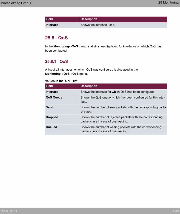
Field Description
Interface Shows the interface used.
25.8 QoS
In the Monitoring->QoS menu, statistics are displayed for interfaces on which QoS has
been configured.
25.8.1 QoS
A list of all interfaces for which QoS was configured is displayed in the
Monitoring->QoS->QoS menu.
Values in the QoS list
Field Description
Interface Shows the interface for which QoS has been configured.
QoS Queue Shows the QoS queue, which has been configured for this inter-
face.
Send Shows the number of sent packets with the corresponding pack-
et class.
Dropped Shows the number of rejected packets with the corresponding
packet class in case of overloading.
Queued Shows the number of waiting packets with the corresponding
packet class in case of overloading.
bintec elmeg GmbH 25 Monitoring
be.IP plus 649

Chapter 26 User Access
The system administrator can set up an individual configuration access interface for the
users. You, the user, can thus display your most important personal settings and individu-
ally customise some of these.
To log in to the configuration interface with your assigned access data, enter your User
Name and Password in the login window.
After successful login, the Status page is displayed. It includes an overview of your most
important settings.
In the Phonebook menu, you can access the System Phonebook and create, edit as well
as delete entries in a user-specific telephone book.
In the Call Data Records menu, you get a detailed overview of the calls you have conduc-
ted and accepted.
The Settings menu contains an overview of current settings of performance features Dir-
ect Call, Call Forwarding and Parallel Ringing. You can individually customise these
here. In addition, you can view general settings and customise access and contact data.
You can also view the settings of the elmeg System Phones assigned to you, and modify
these to your needs.
In the Voice Mail System ->Settings menu, you'll see the current configuration of your indi-
vidual voicemail box, as well as the number of messages present. You can modify several
frequently used voicemail box parameters here. The Voice Mail System ->Messages
menu displays a detailed overview of all received calls.
26.1 Status
The User Access->Status menu displays the most important settings performed for you by
the system administrator.
The menu consists of the following fields:
Values in the User Data list
Field Description
Name, First Name Displays the configured surname and name, if applicable, of
your user.
26 User Access bintec elmeg GmbH
650 be.IP plus

Field Description
Description Displays the configured additional description for your user.
Values in the Internal Numbers &Communication Cost list
Field Description
<Internal Number> Displays the connection charges for the internal numbers as-
signed to your user.
Values in the Further Settings list
Field Description
Current Class of Ser-
vice
Displays the name of the authorisation class to which your user
is assigned.
Dialling Authorization Displays the dial permission for your telephones. This derives
from the setting for the corresponding user class.
Possible values:
• : The telephones have unrestricted dialling
authorisations and can initiate all connections.
• : The telephones can initiate all calls except inter-
national calls. If a number starts with the code for international
dialling, the number cannot be dialled.
• : The telephones can receive incoming external
calls, but cannot initiate any external calls. Internal calls are
possible.
• : The telephones cannot make any national or inter-
national calls. For this dial permission, 10 exception numbers
allowing national or international dialling can be configured.
An exception number can consist of complete call numbers or
sections thereof (e. g. the first numerals).
• : The telephones can make local calls. National and in-
ternational calls are not possible.
• : The telephones do not have authorisation for in-
coming or outgoing external calls. Only internal telephone
calls are possible.
Allow manual trunk
group selection
Indicates whether your user is assigned to an authorisation
class for which manual bundle assignment is allowed. If so, au-
thorised bundles or external connections are displayed.
bintec elmeg GmbH 26 User Access
be.IP plus 651

Field Description
Besides general exchange access, a telephone can also select-
ively use a bundle. Here an external connection is initiated with
the corresponding code for the target assignment of the bundle
and not by dialling the dialling code.
To be able to perform a selective bundle assignment, the au-
thorisation class must possess the appropriate authorisation.
The authorisation can also include bundles that the authorisa-
tion class can otherwise not assign. If a telephone does not pos-
sess the authorisation for selective bundle assignment, or if the
selected bundle is in use, the busy tone is heard after dialling
the code. If Automatic Outside Line is set up for an authorisa-
tion class, users of this authorisation class must press the star
key before selective bundle assignment, then initiate external di-
alling with the code for bundle assignment.
Pick-up Group Displays the number of the group in which calls may be picked
up.
26.2 Phonebook
In the Phonebook menu, telephone book entries are displayed separately according to
System Phonebook and User Phonebook. In User Phonebook the user can create,
modify or delete up to 50 own entries. These entries can only be viewed by the respective
user. These entries are updated via the GUI.
26.2.1 System Phonebook
In the System Phonebook, entries of the overall system created by the administrators are
displayed You cannot modify these.
Values in the System telephone book list
Field Description
Description Displays the subscriber's description. The System Phonebook
is sorted according to these entries.
Phone Number Displays the telephone number.
Speed Dial Number Displays the speed-dial number.
26 User Access bintec elmeg GmbH
652 be.IP plus
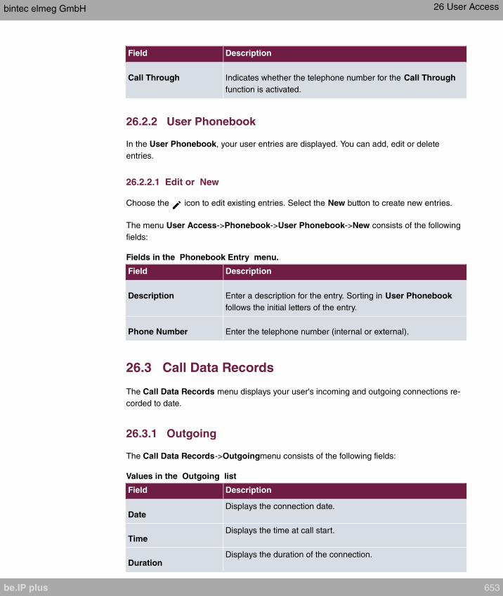
Field Description
Call Through Indicates whether the telephone number for the Call Through
function is activated.
26.2.2 User Phonebook
In the User Phonebook, your user entries are displayed. You can add, edit or delete
entries.
26.2.2.1 Edit or New
Choose the icon to edit existing entries. Select the New button to create new entries.
The menu User Access->Phonebook->User Phonebook->New consists of the following
fields:
Fields in the Phonebook Entry menu.
Field Description
Description Enter a description for the entry. Sorting in User Phonebook
follows the initial letters of the entry.
Phone Number Enter the telephone number (internal or external).
26.3 Call Data Records
The Call Data Records menu displays your user's incoming and outgoing connections re-
corded to date.
26.3.1 Outgoing
The Call Data Records->Outgoingmenu consists of the following fields:
Values in the Outgoing list
Field Description
DateDisplays the connection date.
TimeDisplays the time at call start.
DurationDisplays the duration of the connection.
bintec elmeg GmbH 26 User Access
be.IP plus 653

Field Description
UserDisplays the user who called.
Int. No.Displays the user's internal number.
Called NumberDisplays the dialled number.
Project CodeDisplays the call project number, if any.
InterfaceDisplays the interface over which the external connection was
routed.
CostsDisplays the connection charge, but only if the provider trans-
mits the corresponding data.
26.3.2 Incoming
The Call Data Records->Incoming menu consists of the following fields:
Values in the Incoming list
Field Description
DateDisplays the connection date.
TimeDisplays the time at call start.
DurationDisplays the duration of the connection.
UserDisplays the user who was called.
Int. No.Displays the user's internal number.
External NumberDisplays the caller's number.
Project CodeDisplays the call project number, if any.
InterfaceDisplays the interface over which the connection from outside
was routed.
26.4 Call List
The menu Applications->Call List lists details of incoming and outgoing calls. Which kind
of calls and how many of them are included can be spcified in the submenu General.
26 User Access bintec elmeg GmbH
654 be.IP plus

26.4.1 Incoming
The Applications->Call List->Incoming menu contains information that permits the monit-
oring of incoming activities.
The menu consists of the following fields:
Fields in the Incoming menu
Field Description
Date Displays the connection date.
Time Displays the time at call start.
Type Displays the type of the connection.
Int. No. Displays the user's internal number.
Caller NumberDisplays the caller's number.
Trunk Number Displays the port number.
Interface Displays the interface over which the connection from outside
was routed.
DeleteYou can use the Select all and Deselect all buttons for all the
devices displayed.
26.4.2 Outgoing
The Applications->Call List->Outgoing menu contains information that permits the monit-
oring of outgoing activities.
The menu consists of the following fields:
Fields in the Outgoing menu
Field Description
Date Displays the connection date.
Time Displays the time at call start.
bintec elmeg GmbH 26 User Access
be.IP plus 655
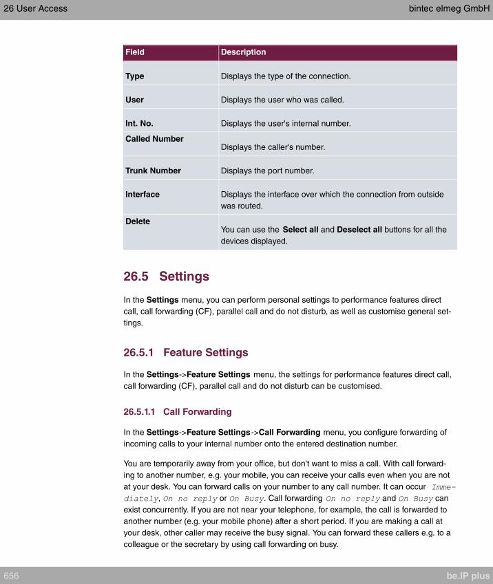
Field Description
Type Displays the type of the connection.
User Displays the user who was called.
Int. No. Displays the user's internal number.
Called NumberDisplays the caller's number.
Trunk Number Displays the port number.
Interface Displays the interface over which the connection from outside
was routed.
DeleteYou can use the Select all and Deselect all buttons for all the
devices displayed.
26.5 Settings
In the Settings menu, you can perform personal settings to performance features direct
call, call forwarding (CF), parallel call and do not disturb, as well as customise general set-
tings.
26.5.1 Feature Settings
In the Settings->Feature Settings menu, the settings for performance features direct call,
call forwarding (CF), parallel call and do not disturb can be customised.
26.5.1.1 Call Forwarding
In the Settings->Feature Settings->Call Forwarding menu, you configure forwarding of
incoming calls to your internal number onto the entered destination number.
You are temporarily away from your office, but don't want to miss a call. With call forward-
ing to another number, e.g. your mobile, you can receive your calls even when you are not
at your desk. You can forward calls on your number to any call number. It can occur
, or . Call forwarding and can
exist concurrently. If you are not near your telephone, for example, the call is forwarded to
another number (e.g. your mobile phone) after a short period. If you are making a call at
your desk, other caller may receive the busy signal. You can forward these callers e.g. to a
colleague or the secretary by using call forwarding on busy.
26 User Access bintec elmeg GmbH
656 be.IP plus

Calls can be forwarded to internal subscriber numbers, internal team numbers or external
numbers When the number to which calls shall be forwarded is entered, the system auto-
matically checks whether it's an internal or external number.
To continue with configuring, click the symbol.
Select the button to go to the IP1x0 telephone user interface administrator page. This is
described in the telephone user guide!
The Settings->Feature Settings->Call Forwarding menu consists of the following fields:
Fields in the Call Forwarding menu.
Field Description
Active Function Select whether to enable the call forwarding (CF) function for
your telephone.
The function is enabled with
The function is disabled by default.
Type Select when incoming calls shall be forwarded to the specified
internal number.
Possible values:
•
•
• (default value)
•
Destination on no
Reply
Enter the number to which incoming calls shall be forwarded
after time.
Destination on BusyEnter the number to which incoming calls shall be forwarded on
busy.
Destination immedi-
ately
Enter the number to which incoming calls shall be forwarded im-
mediately.
26.5.1.2 Parallel Ringing
In the Settings->Feature Settings->Parallel Ringing menu, you configure which calls
should be signalled to your terminal.
bintec elmeg GmbH 26 User Access
be.IP plus 657

The menu consists of the following fields:
Fields in the Parallel Ringing menu.
Field Description
Active Function Select whether to enable the parallel call function for your tele-
phone.
The function is enabled with
The function is disabled by default.
External Number Under enter the external telephone
number to which a call should be signalled in parallel. If a mo-
bile number and a call number are configured for personal use,
these are displayed in or
and can be selected.
26.5.1.3 Direct Call
You wish to install your telephone in such a way that connection to a specific call number is
set up even without entry of the number (e. g. emergency phone). You are not at home.
However, there is someone at home who needs to be able to reach you quickly and easily
by telephone if necessary (e. g. children or grandparents). If you have set up the Direct Call
function for your telephone, the telephone receiver only needs to be picked up. After a time
period without further entries set in configuration, the system automatically dials the con-
figured direct call number.
If you do not dial within the specified period from picking up the receiver, automatic dialling
is initiated.
The Settings->Feature Settings->Direct Call menu consists of the following fields:
Fields in the Direct Call menu.
Field Description
Active Function Select whether to enable the direct call function for your tele-
phone.
The function is enabled with
The function is disabled by default.
Number Select which number to use for direct call.
26 User Access bintec elmeg GmbH
658 be.IP plus
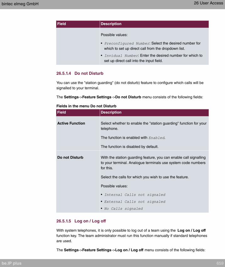
Field Description
Possible values:
• : Select the desired number for
which to set up direct call from the dropdown list.
• : Enter the desired number for which to
set up direct call into the input field.
26.5.1.4 Do not Disturb
You can use the "station guarding" (do not disturb) feature to configure which calls will be
signalled to your terminal.
The Settings->Feature Settings->Do not Disturb menu consists of the following fields:
Fields in the menu Do not Disturb
Field Description
Active Function Select whether to enable the "station guarding" function for your
telephone.
The function is enabled with .
The function is disabled by default.
Do not Disturb With the station guarding feature, you can enable call signalling
to your terminal. Analogue terminals use system code numbers
for this.
Select the calls for which you wish to use the feature.
Possible values:
•
•
•
26.5.1.5 Log on / Log off
With system telephones, it is only possible to log out of a team using the Log on / Log off
function key. The team administrator must run this function manually if standard telephones
are used.
The Settings->Feature Settings->Log on / Log off menu consists of the following fields:
bintec elmeg GmbH 26 User Access
be.IP plus 659

Fields in the menu Log on / Log off
Field Description
Description Shows which teams the user belongs to.
Status Select whether the team member shall be logged in or out of the
team.
The function is activated by selecting .
The function is enabled by default.
26.5.2 General Settings
Your user's most important settings are listed in the Settings->General Settings menu.
Personal access data (configuration password, IP phone password) as well as mobile and
home office numbers can be customised.
The menu consists of the following fields:
Fields in the User Data menu.
Field Description
Name Displays your user's name.
Description Displays the additional description for your user.
Login Name Displays your user name for login to the user configuration inter-
face.
Password for HTML
Configuration Access
If you wish to change your password for access to the user con-
figuration interface, enter a new password here. To check, you
can display the password in plain text by clicking the Show op-
tion.
Password for IP Phone
Registration
If you wish to change your password for IP telephone login,
enter a new password here. To check, you can display the
password in plain text by clicking the Show option.
PIN for Phone Access If you wish to change the PIN for your personal voicebox, enter
a new PIN here. To check, you can display the password in
plain text by clicking the Show option.
26 User Access bintec elmeg GmbH
660 be.IP plus
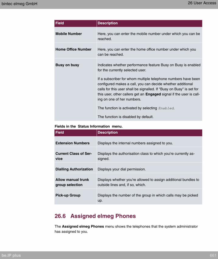
Field Description
Mobile Number Here, you can enter the mobile number under which you can be
reached.
Home Office Number Here, you can enter the home office number under which you
can be reached.
Busy on busy Indicates whether performance feature Busy on Busy is enabled
for the currently selected user.
If a subscriber for whom multiple telephone numbers have been
configured makes a call, you can decide whether additional
calls for this user shall be signalled. If "Busy on Busy" is set for
this user, other callers get an Engaged signal if the user is call-
ing on one of her numbers.
The function is activated by selecting .
The function is disabled by default.
Fields in the Status Information menu.
Field Description
Extension Numbers Displays the internal numbers assigned to you.
Current Class of Ser-
vice
Displays the authorisation class to which you're currently as-
signed.
Dialling Authorization Displays your dial permission.
Allow manual trunk
group selection
Displays whether you're allowed to assign additional bundles to
outside lines and, if so, which.
Pick-up Group Displays the number of the group in which calls may be picked
up.
26.6 Assigned elmeg Phones
The Assigned elmeg Phones menu shows the telephones that the system administrator
has assigned to you.
bintec elmeg GmbH 26 User Access
be.IP plus 661

Note
The Assigned elmeg Phones menu is only displayed if you've already been assigned
system telephones by the administrator.
26.6.1 Assigned elmeg Phones
The Assigned elmeg Phones->Assigned elmeg Phones menu shows a list with the key
information about your telephone. The symbol takes you to the IP1x0 phone's configur-
ation interface.
Select the symbol to reset the phone's user password.
The Assigned elmeg Phones->Assigned elmeg Phones menu consists of the follow-
ing fields:
Fields in the System Phone menu
Field Description
User password Select whether the user password should be reset.
The function is activated by selecting .
The function is disabled by default.
As soon as you select the OK button, the password is reset to
the default setting.
26.7 elmeg System Phones
The menu elmeg System Phones displays the system telephones assigned to you by the
system administrator.
Note
The elmeg System Phones menu is only displayed if you've already been assigned
system telephones by the administrator.
26 User Access bintec elmeg GmbH
662 be.IP plus

26.7.1 Assigned System Phones
The system telephone offers typical system performance features associated with bintec el-
meg systems. For example:
• Dialling from the system phone book
• Announcement and simplex operation with other system telephones on the system
• Function keys for control of system performance features (enable call options, login/
logout in teams, line keys, connection keys). The status of defined performance features
can be indicated via LED's assigned to individual function keys.
Note
Configuration modifications are transmitted to the system telephones at the earliest 30
seconds after confirming the modification with the Apply button.
26.7.1.1 Settings
In the elmeg System Phones->Assigned System Phones->Settings you can release
specific performance features and functions for your system telephone.
The menu consists of the following fields:
Fields in the menu Basic Settings
Field Description
Headset Support Not for S530 and S560.
Select whether the headset should automatically accept calls.
Note
If you wish to use a headset, you must configure a headset
key and a key for automatic call acceptance on your PABX
system. On the system telephone, you must select a head-
set type and enable the key for automatic call acceptance.
Call Waiting Select whether another call shall be supported for this tele-
phone through call waiting or a display notification.
The function is activated by selecting .
bintec elmeg GmbH 26 User Access
be.IP plus 663
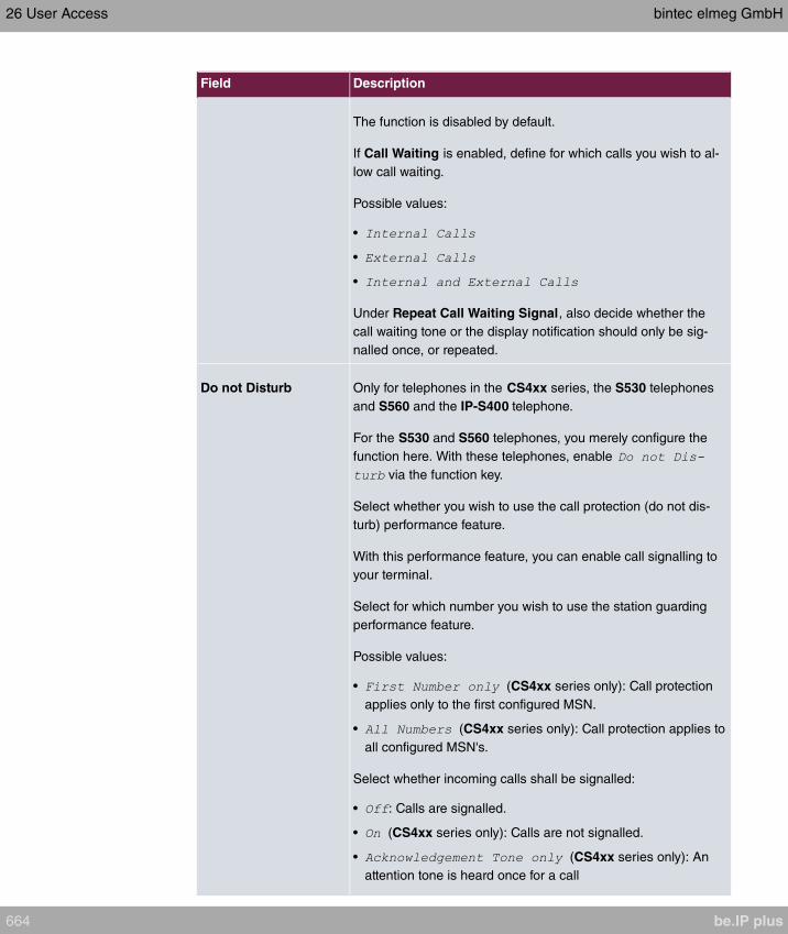
Field Description
The function is disabled by default.
If Call Waiting is enabled, define for which calls you wish to al-
low call waiting.
Possible values:
•
•
•
Under Repeat Call Waiting Signal, also decide whether the
call waiting tone or the display notification should only be sig-
nalled once, or repeated.
Do not Disturb Only for telephones in the CS4xx series, the S530 telephones
and S560 and the IP-S400 telephone.
For the S530 and S560 telephones, you merely configure the
function here. With these telephones, enable
via the function key.
Select whether you wish to use the call protection (do not dis-
turb) performance feature.
With this performance feature, you can enable call signalling to
your terminal.
Select for which number you wish to use the station guarding
performance feature.
Possible values:
• (CS4xx series only): Call protection
applies only to the first configured MSN.
• (CS4xx series only): Call protection applies to
all configured MSN's.
Select whether incoming calls shall be signalled:
• : Calls are signalled.
• (CS4xx series only): Calls are not signalled.
• (CS4xx series only): An
attention tone is heard once for a call
26 User Access bintec elmeg GmbH
664 be.IP plus

Field Description
• (only S530 and S560)
• (only S530 and S560)
• (only S530 and S560)
• (only S530 and S560)
• (only S530 and S560)
The menu Advanced Settings consists of the following fields:
Fields in the menu Advanced Settings
Field Description
Status LED Select whether and, if so, which events should be signalled by
the system telephone status LED.
Possible values:
• : The status LED function is not used.
• : The status LED signals calls and new mes-
sages.
• : The status LED only signals new mes-
sages (MWI).
• (only S5x0)
• (only S5x0)
• (only S5x0)
You can use the options , and
individually, or combine them freely.
Directory Softkey Only for telephones in the CS4xx series
Select whether calls shall be made with the softkey entries from
the system phone book ( ) or from the telephone phone
book ( ).
Conversation Display Not for S5x0
Select which information shall be indicated in the system tele-
phone display during a call.
Possible values:
•
bintec elmeg GmbH 26 User Access
be.IP plus 665

Field Description
•
•
•
•
•
Default Signalling dur-
ing Calls
Select whether DTMF signals or keypad functions shall be
transmitted into the system in call status. You can use special
functions during a call by entering character and numerical se-
quences. These entries must be made as keypad or MFV se-
quences, depending on the function to be used. You can define
whether MFV or keypad functions are possible in the basic set-
ting during a call.
Possible values:
• (default value)
•
Automatic Call Pick-up Select the period after which calls to this system telephone
should be automatically accepted without you having to pick up
the receiver or press the loudspeaker key.
Possible values:
•
•
•
• (only S5x0)
• (only S5x0)
• (only S5x0)
Mute after hands-free
Calling
Not for S5x0, CS290, CS290-U
You can dial the number of a subscriber without picking up the
receiver (e. g. hands-free). Here, you have the choice of wheth-
er the built-in microphone shall be switched on immediately or
only after pressing of the corresponding softkey. If the micro-
26 User Access bintec elmeg GmbH
666 be.IP plus
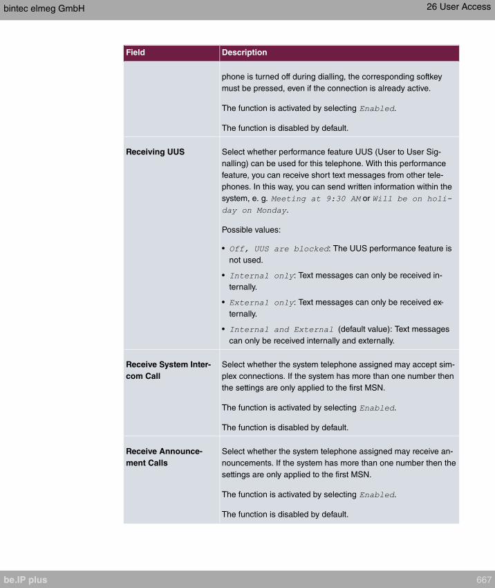
Field Description
phone is turned off during dialling, the corresponding softkey
must be pressed, even if the connection is already active.
The function is activated by selecting .
The function is disabled by default.
Receiving UUS Select whether performance feature UUS (User to User Sig-
nalling) can be used for this telephone. With this performance
feature, you can receive short text messages from other tele-
phones. In this way, you can send written information within the
system, e. g. or
.
Possible values:
• : The UUS performance feature is
not used.
• : Text messages can only be received in-
ternally.
• : Text messages can only be received ex-
ternally.
• (default value): Text messages
can only be received internally and externally.
Receive System Inter-
com Call
Select whether the system telephone assigned may accept sim-
plex connections. If the system has more than one number then
the settings are only applied to the first MSN.
The function is activated by selecting .
The function is disabled by default.
Receive Announce-
ment Calls
Select whether the system telephone assigned may receive an-
nouncements. If the system has more than one number then the
settings are only applied to the first MSN.
The function is activated by selecting .
The function is disabled by default.
bintec elmeg GmbH 26 User Access
be.IP plus 667
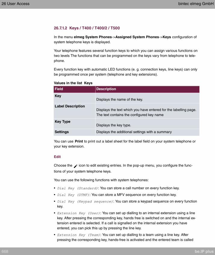
26.7.1.2 Keys / T400 / T400/2 / T500
In the menu elmeg System Phones->Assigned System Phones->Keys configuration of
system telephone keys is displayed.
Your telephone features several function keys to which you can assign various functions on
two levels The functions that can be programmed on the keys vary from telephone to tele-
phone.
Every function key with automatic LED functions (e. g. connection keys, line keys) can only
be programmed once per system (telephone and key extensions).
Values in the list Keys
Field Description
KeyDisplays the name of the key.
Label DescriptionDisplays the text which you have entered for the labelling page.
The text contains the configured key name
Key TypeDisplays the key type.
Settings Displays the additional settings with a summary
You can use Print to print out a label sheet for the label field on your system telephone or
your key extension.
Edit
Choose the icon to edit existing entries. In the pop-up menu, you configure the func-
tions of your system telephone keys.
You can use the following functions with system telephones:
• : You can store a call number on every function key.
• : You can store a MFV sequence on every function key.
• : You can store a keypad sequence on every function
key.
• : You can set up dialling to an internal extension using a line
key. After pressing the corresponding key, hands free is switched on and the internal ex-
tension entered is selected. If a call is signalled on the internal extension you have
entered, you can pick this up by pressing the line key.
• : You can set up dialling to a team using a line key. After
pressing the corresponding key, hands-free is activated and the entered team is called
26 User Access bintec elmeg GmbH
668 be.IP plus
according to its enabled call option. If a call is signalled for the entered team, you can
pick it up by pressing this connection key.
• : An ISDN connection or a VoIP provider is set up under a connection key.
If this key is pressed, automatic hands-free is enabled and the corresponding ISDN con-
nection is assigned. You then hear the external dialling tone. If an external call is sig-
nalled on another internal telephone, you can pick it up by pressing this line key.
• : If you are entered as a subscriber in the call assignments
for one or more teams, you can set up a key so that you can control the call signalling of
your telephone. If you're logged in, team calls are signalled to your telephone. If you are
logged out, no team calls will be signalled.
The call numbers entered in the telephone can be logged in/logged out from a team us-
ing a set function key (MSN-1... MSN-9). Before entering a team number, you must select
the telephone call number index (MSN) that is entered in the corresponding team call as-
signments.
• : You can set up a connection to another tele-
phone without this connection having to be actively accepted. As soon as the telephone
has accepted the announcement, the connection is established and the announcement
key LED is enabled. The announcement can be ended by renewed pressing of the an-
nouncement key or by pressing the loudspeaker key. The LED switches off again at con-
clusion of the announcement.
• : You can configure an announcement for a
team by setting up a function key. The way this works is the same as that described
above.
• : You can also selectively deny or allow an-
nouncements using a function key. To use announcements, you must be authorised for
the corresponding authorisation class.
• : You can set up a key is such a way that a connection to
the specified telephone is established without this connection having to be actively ac-
cepted.
• : You can set up a key in such a way that the sim-
plex operation function is allowed or denied. To use simplex operation, the function must
be allowed in the corresponding authorisation class.
• / : You can set up a key as a special line key. The Boss
telephone and Secretary telephone properties are saved in both telephones with these
keys.
• : You can set up a key in such a way that incoming calls to the
Boss telephone are automatically routed to the Secretary telephone.
• : You can set up a key so that delayed call diversion is set
up for a specific number (MSN) on your system telephone. Pressing the key when the
phone is not in use turns call forwarding on and off. Configuring call forwarding with a
bintec elmeg GmbH 26 User Access
be.IP plus 669
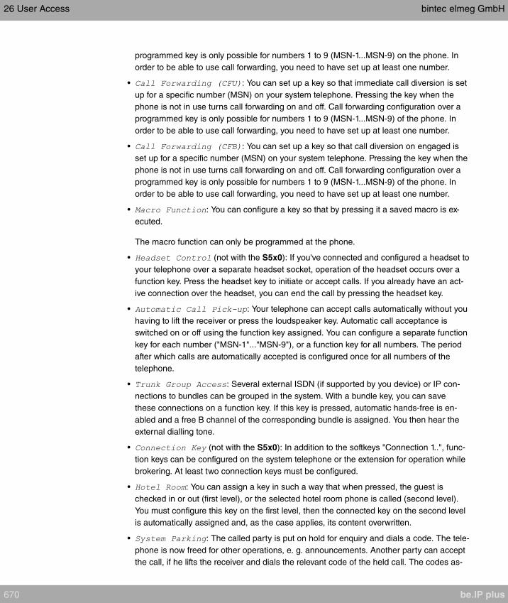
programmed key is only possible for numbers 1 to 9 (MSN-1...MSN-9) on the phone. In
order to be able to use call forwarding, you need to have set up at least one number.
• : You can set up a key so that immediate call diversion is set
up for a specific number (MSN) on your system telephone. Pressing the key when the
phone is not in use turns call forwarding on and off. Call forwarding configuration over a
programmed key is only possible for numbers 1 to 9 (MSN-1...MSN-9) of the phone. In
order to be able to use call forwarding, you need to have set up at least one number.
• : You can set up a key so that call diversion on engaged is
set up for a specific number (MSN) on your system telephone. Pressing the key when the
phone is not in use turns call forwarding on and off. Call forwarding configuration over a
programmed key is only possible for numbers 1 to 9 (MSN-1...MSN-9) of the phone. In
order to be able to use call forwarding, you need to have set up at least one number.
• : You can configure a key so that by pressing it a saved macro is ex-
ecuted.
The macro function can only be programmed at the phone.
• (not with the S5x0): If you've connected and configured a headset to
your telephone over a separate headset socket, operation of the headset occurs over a
function key. Press the headset key to initiate or accept calls. If you already have an act-
ive connection over the headset, you can end the call by pressing the headset key.
• : Your telephone can accept calls automatically without you
having to lift the receiver or press the loudspeaker key. Automatic call acceptance is
switched on or off using the function key assigned. You can configure a separate function
key for each number ("MSN-1"..."MSN-9"), or a function key for all numbers. The period
after which calls are automatically accepted is configured once for all numbers of the
telephone.
• : Several external ISDN (if supported by you device) or IP con-
nections to bundles can be grouped in the system. With a bundle key, you can save
these connections on a function key. If this key is pressed, automatic hands-free is en-
abled and a free B channel of the corresponding bundle is assigned. You then hear the
external dialling tone.
• (not with the S5x0): In addition to the softkeys "Connection 1..", func-
tion keys can be configured on the system telephone or the extension for operation while
brokering. At least two connection keys must be configured.
• : You can assign a key in such a way that when pressed, the guest is
checked in or out (first level), or the selected hotel room phone is called (second level).
You must configure this key on the first level, then the connected key on the second level
is automatically assigned and, as the case applies, its content overwritten.
• : The called party is put on hold for enquiry and dials a code. The tele-
phone is now freed for other operations, e. g. announcements. Another party can accept
the call, if he lifts the receiver and dials the relevant code of the held call. The codes as-
26 User Access bintec elmeg GmbH
670 be.IP plus

signed by the PABX can also be entered in the function keys of one or more system tele-
phones. If a call is set to open hold for enquiry by pressing the function key, this is indic-
ated by flashing LEDs on the function keys for the system telephones set up for this. The
call is transferred by pressing the corresponding function key. This performance feature
is only possible if only one call is on hold.
• : You can configure a key so that when it is pressed, an agent's
post-processing time is switched on or off at a team call centre (first level), or extended
(second level).
• : You can configure a key so that by pressing it night operation is switched
on or off.
Note
To manually switch night operation off again, the authorisation class Switch sig-
nalling variants manually must be enabled.
• (only S5x0): If a parallel call to another telephone is configured,
both connections will ring when a call comes in. The call is accepted where first picked
up.
• (only S5x0): With this key, you can access second level functions.
• (only S5x0): With this key, you enable or disable the Do not Disturb
function which you have configured under Terminals->elmeg System Phones->System
Phone->Settings.
The elmeg System Phones->Assigned System Phones->Keys-> Edit menu consists of
the following fields:
Fields in the menu Phone: Type x
Field Description
Key name Enter a name for the key to be used as text for the correspond-
ing key when the ID labels are printed.
Key TypeDepending on the model, the telephones feature from 5 to 15
keys on which functions may be assigned over two levels. You
can reach the second layer of function keys by pressing the
keys twice. This must be done quickly. With S5x0 devices, you
can alternately use the function key. With the optional
bintec elmeg key extensions, you have access to additional
twice-assignable function keys.
Possible values:
•
bintec elmeg GmbH 26 User Access
be.IP plus 671
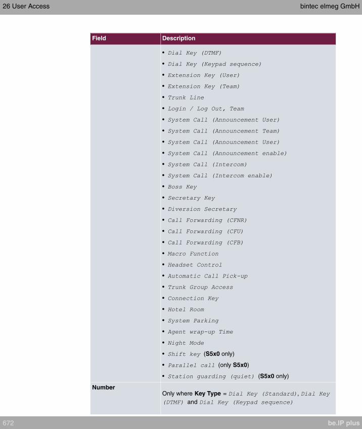
Field Description
•
•
•
•
•
•
•
•
•
•
•
•
•
•
•
•
•
•
•
•
•
•
•
•
•
•
•
• (S5x0 only)
• (only S5x0)
• (S5x0 only)
NumberOnly where Key Type = ,
and
26 User Access bintec elmeg GmbH
672 be.IP plus

Field Description
You can save a number, an MFV sequence or a keypad se-
quence on every function key. Enter the call number or the code
for the MFV/keypad sequence.
Internal Number Where Key Type =
Select the internal number of a user to be called when this key
is pressed.
Where Key Type =
Select the internal number of a user to whose telephone an an-
nouncement shall be sent.
When Key Type =
Select the internal number of a team to be logged into or out of
when this key is pressed.
When Key Type =
Select the internal number of a user on whose telephone an an-
nouncement shall be made.
When Key Type =
Select the internal number of a user with which you wish to con-
duct simplex operations.
When Key Type = ,
,
Select the internal number of a telephone MSN from which the
indicated destination number can be forwarded
When Key Type =
Select the internal number of this telephone, on which incoming
calls shall be automatically accepted.
When Key Type =
Select the internal number of a hotel guest.
When Key Type =
Select the internal number of a user whose post-processing
bintec elmeg GmbH 26 User Access
be.IP plus 673
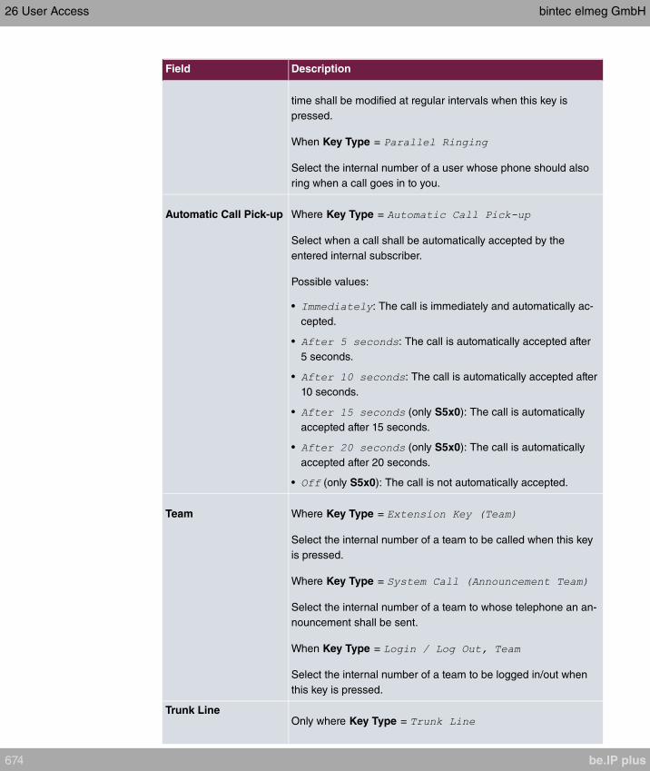
Field Description
time shall be modified at regular intervals when this key is
pressed.
When Key Type =
Select the internal number of a user whose phone should also
ring when a call goes in to you.
Automatic Call Pick-up Where Key Type =
Select when a call shall be automatically accepted by the
entered internal subscriber.
Possible values:
• : The call is immediately and automatically ac-
cepted.
• : The call is automatically accepted after
5 seconds.
• : The call is automatically accepted after
10 seconds.
• (only S5x0): The call is automatically
accepted after 15 seconds.
• (only S5x0): The call is automatically
accepted after 20 seconds.
• (only S5x0): The call is not automatically accepted.
Team Where Key Type =
Select the internal number of a team to be called when this key
is pressed.
Where Key Type =
Select the internal number of a team to whose telephone an an-
nouncement shall be sent.
When Key Type =
Select the internal number of a team to be logged in/out when
this key is pressed.
Trunk LineOnly where Key Type =
26 User Access bintec elmeg GmbH
674 be.IP plus

Field Description
Select the external connection over which an external call shall
be set up when this key is pressed.
Number of Secretary
Phone
Only where Key Type =
Select the internal number of the secretary telephone. The sec-
retary telephone is called when this key is pressed.
Number of Boss Phone Only where Key Type =
Select the internal number of the Boss telephone. The Boss
telephone is called when this key is pressed.
Target Number "On no
reply" Only where Key Type =
Enter the number to which calls shall be forwarded immediately
when call forwarding is enabled.
Target Number "Imme-
diate"
Only where Key Type =
Enter the number to which calls shall be forwarded when call
forwarding when busy is enabled.
Target Number "On
busy"
Only where Key Type =
Enter the number to which calls shall be forwarded when call
forwarding is enabled when the call is not answered.
Trunk Group Access Only where Key Type =
Select the bundle via which an outside call shall be set up.
Waiting Queue Only where Key Type =
Select the queue in which the current call should be held.
Move
Select the icon to move configured function keys.
Fields in the menu Phone
Field Description
Key name Displays the name of the key.
bintec elmeg GmbH 26 User Access
be.IP plus 675

Field Description
Key Type Displays the key type.
Settings Displays the additional settings with a summary
Fields in the menu Move to
Field Description
Phone Displays your system telephone. In User Access you can only
move keys within your own telephone key extension combina-
tion.
Module Select telephone or a key extension module.
Key Select the key to which you wish to transfer the configured func-
tion.
26.7.1.3 Device Info
In the elmeg System Phones->Assigned System Phones->Device Info menu the sys-
tem data read out of the system telephone are displayed.
Meaning of the list entries
Description Meaning
Description Displays the entered description of the telephone.
Phone Type Displays the type of telephone.
Serial Number Displays the serial number of the telephone.
Software Version Displays the current version of the telephone software.
Release Date and Time Displays the date and time of the telephone software version.
Last Device Configura-
tion
Displays the date and time of the last telephone configuration.
Answering Machine Displays whether an answering machine module is inserted in
the telephone (Yes) or not (No).
Meaning of the key extension
26 User Access bintec elmeg GmbH
676 be.IP plus
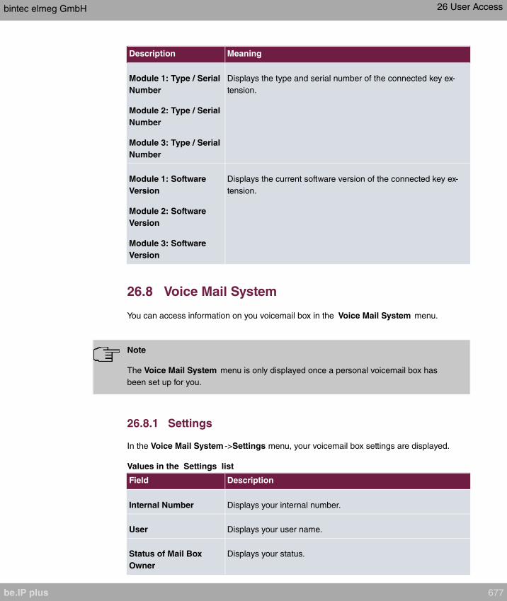
Description Meaning
Module 1: Type / Serial
Number
Module 2: Type / Serial
Number
Module 3: Type / Serial
Number
Displays the type and serial number of the connected key ex-
tension.
Module 1: Software
Version
Module 2: Software
Version
Module 3: Software
Version
Displays the current software version of the connected key ex-
tension.
26.8 Voice Mail System
You can access information on you voicemail box in the Voice Mail System menu.
Note
The Voice Mail System menu is only displayed once a personal voicemail box has
been set up for you.
26.8.1 Settings
In the Voice Mail System ->Settings menu, your voicemail box settings are displayed.
Values in the Settings list
Field Description
Internal Number Displays your internal number.
User Displays your user name.
Status of Mail Box
Owner
Displays your status.
bintec elmeg GmbH 26 User Access
be.IP plus 677
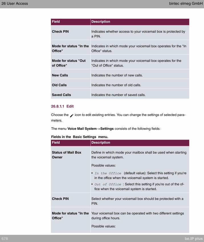
Field Description
Check PIN Indicates whether access to your voicemail box is protected by
a PIN.
Mode for status "In the
Office"
Indicates in which mode your voicemail box operates for the "In
Office" status.
Mode for status "Out
of Office"
Indicates in which mode your voicemail box operates for the
"Out of Office" status.
New Calls Indicates the number of new calls.
Old Calls Indicates the number of old calls.
Saved Calls Indicates the number of saved calls.
26.8.1.1 Edit
Choose the icon to edit existing entries. You can change the settings of selected para-
meters.
The menu Voice Mail System ->Settings consists of the following fields:
Fields in the Basic Settings menu.
Field Description
Status of Mail Box
Owner
Define in which mode your mailbox shall be used when starting
the voicemail system.
Possible values:
• (default value): Select this setting if you're
in the office when the voicemail system is started.
• : Select this setting if you're out of the of-
fice when the voicemail system is started.
Check PIN Select whether your voicemail box should be protected with a
PIN.
Mode for status "In the
Office"
Your voicemail box can be operated with two different settings
during office hours.
Possible values:
26 User Access bintec elmeg GmbH
678 be.IP plus
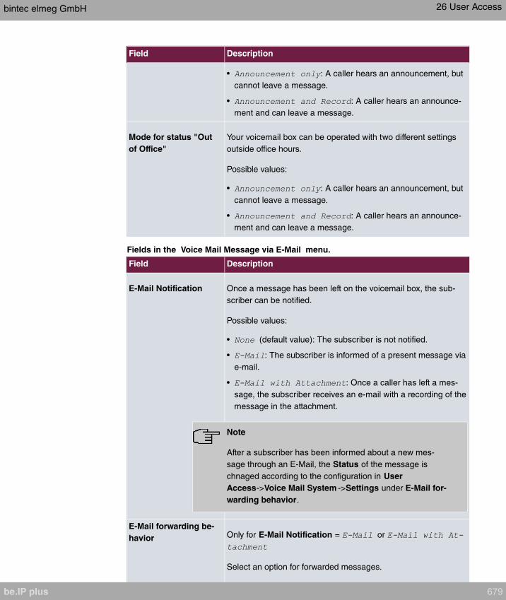
Field Description
• : A caller hears an announcement, but
cannot leave a message.
• : A caller hears an announce-
ment and can leave a message.
Mode for status "Out
of Office"
Your voicemail box can be operated with two different settings
outside office hours.
Possible values:
• : A caller hears an announcement, but
cannot leave a message.
• : A caller hears an announce-
ment and can leave a message.
Fields in the Voice Mail Message via E-Mail menu.
Field Description
E-Mail Notification Once a message has been left on the voicemail box, the sub-
scriber can be notified.
Possible values:
• (default value): The subscriber is not notified.
• : The subscriber is informed of a present message via
e-mail.
• : Once a caller has left a mes-
sage, the subscriber receives an e-mail with a recording of the
message in the attachment.
Note
After a subscriber has been informed about a new mes-
sage through an E-Mail, the Status of the message is
chnaged according to the configuration in User
Access->Voice Mail System ->Settings under E-Mail for-
warding behavior.
E-Mail forwarding be-
havior Only for E-Mail Notification = or
Select an option for forwarded messages.
bintec elmeg GmbH 26 User Access
be.IP plus 679
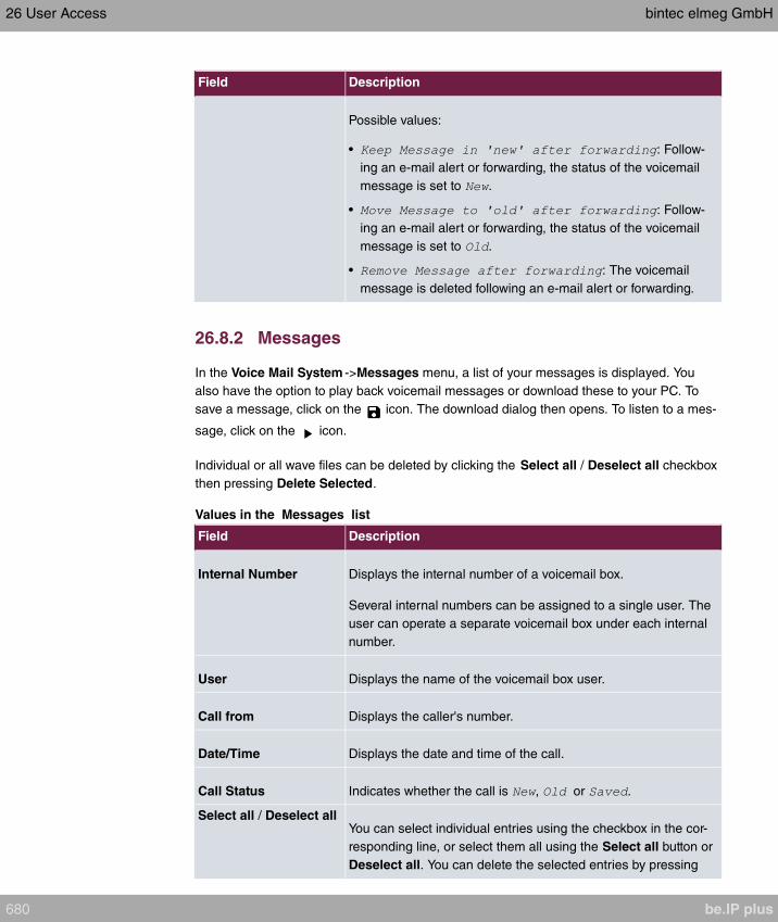
Field Description
Possible values:
• : Follow-
ing an e-mail alert or forwarding, the status of the voicemail
message is set to .
• : Follow-
ing an e-mail alert or forwarding, the status of the voicemail
message is set to .
• : The voicemail
message is deleted following an e-mail alert or forwarding.
26.8.2 Messages
In the Voice Mail System ->Messages menu, a list of your messages is displayed. You
also have the option to play back voicemail messages or download these to your PC. To
save a message, click on the icon. The download dialog then opens. To listen to a mes-
sage, click on the icon.
Individual or all wave files can be deleted by clicking the Select all / Deselect all checkbox
then pressing Delete Selected.
Values in the Messages list
Field Description
Internal Number Displays the internal number of a voicemail box.
Several internal numbers can be assigned to a single user. The
user can operate a separate voicemail box under each internal
number.
User Displays the name of the voicemail box user.
Call from Displays the caller's number.
Date/Time Displays the date and time of the call.
Call Status Indicates whether the call is , or .
Select all / Deselect allYou can select individual entries using the checkbox in the cor-
responding line, or select them all using the Select all button or
Deselect all. You can delete the selected entries by pressing
26 User Access bintec elmeg GmbH
680 be.IP plus

Field Description
the Delete Selected option.
bintec elmeg GmbH 26 User Access
be.IP plus 681

Glossary
2G See GSM.
3DES See DES.
3G See UMTS.
4G See LTE.
802.11 The 802.11 norm describes wireless LAN (WLAN). There are a vari-
ety of amendments: 802.11a: Gross data transfer rates: 54 Mbit/s,
frequency band: 5 GHz, 802.11b/g: Gross data transfer rates: 11
Mbit/s, frequency band: 2.4 GHz, 802.11g: Gross data transfer
rates: 54 Mbit/s, frequency band: 2.4 GHz, 802.11n: Gross data
transfer rates: 600 Mbit/s, frequency band: 2.4 GHz (optional: 5
GHz)
A-subscriber The A-subscriber is the caller.
a/b interface An a/b interface is used to connect an analogue terminal. In the
case of an ISDN terminal (terminal adapter) with a/b interface, a
connected analogue terminal is enabled to use the supported ISDN
performance features.
Access client Client mode is an operating mode of a wireless access point (AP) in
which the latter behaves like a wireless adapter vis-a-vis the higher
level AP. With an AP run in client mode, individual computers or en-
tire sub-networks can be connected to higher level networks.
Access point An access point (AP) is a device for wirelessly connecting clients
(computers). The AP thus serves to create a wireless network
(WLAN) and connect that WLAN to a wired Ethernet network
(bridging).
Accounting Accounting refers to the recording of connection data, e.g. date,
time, connection duration, charging information and number of data
packets transferred.
Activity monitor The activity monitor is used to oversee the status of physical and vir-
tual device interfaces.
Ad-hoc network In an ad-hoc network, individual clients connect to an independent
wireless LAN via a wireless adapter. Ad-hoc networks work inde-
pendently, with no access point on a peer-to-peer basis. The ad-hoc
mode is also referred to as IBSS (Independent Basic Service Set)
Glossary bintec elmeg GmbH
682 be.IP plus
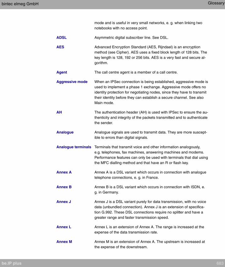
mode and is useful in very small networks, e. g. when linking two
notebooks with no access point.
ADSL Asymmetric digital subscriber line. See DSL.
AES Advanced Encryption Standard (AES, Rijndael) is an encryption
method (see Cipher). AES uses a fixed block length of 128 bits. The
key length is 128, 192 or 256 bits. AES is a very fast and secure al-
gorithm.
Agent The call centre agent is a member of a call centre.
Aggressive mode When an IPSec connection is being established, aggressive mode is
used to implement a phase 1 exchange. Aggressive mode offers no
identity protection for negotiating nodes, since they have to transmit
their identity before they can establish a secure channel. See also
Main mode.
AH The authentication header (AH) is used with IPSec to ensure the au-
thenticity and integrity of the packets transmitted and to authenticate
the sender.
Analogue Analogue signals are used to transmit data. They are more suscept-
ible to errors than digital signals.
Analogue terminals Terminals that transmit voice and other information analogously,
e.g. telephones, fax machines, answering machines and modems.
Performance features can only be used with terminals that dial using
the MFC dialling method and that have an R or flash key.
Annex A Annex A is a DSL variant which occurs in connection with analogue
telephone connections, e. g. in France.
Annex B Annex B is a DSL variant which occurs in connection with ISDN, e.
g. in Germany.
Annex J Annex J is a DSL variant purely for data transmission, with no voice
data (unbundled connection). Annex J is an extension of specifica-
tion G.992. These DSL connections require no splitter and have a
greater range and faster transmission speed.
Annex L Annex L is an extension of Annex A. The range is increased at the
expense of the data transmission rate.
Annex M Annex M is an extension of Annex A. The upstream is increased at
the expense of the downstream.
bintec elmeg GmbH Glossary
be.IP plus 683
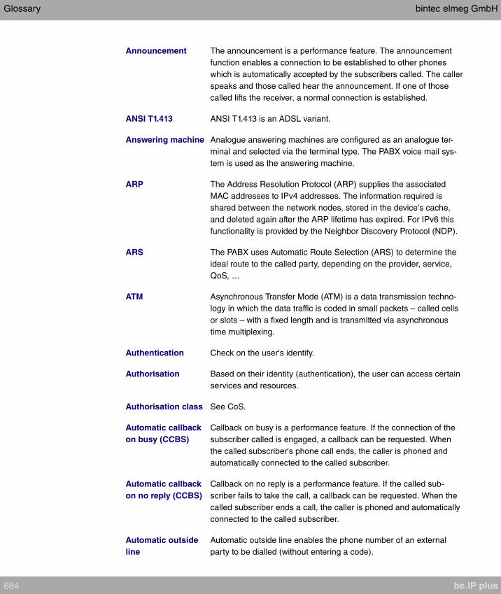
Announcement The announcement is a performance feature. The announcement
function enables a connection to be established to other phones
which is automatically accepted by the subscribers called. The caller
speaks and those called hear the announcement. If one of those
called lifts the receiver, a normal connection is established.
ANSI T1.413 ANSI T1.413 is an ADSL variant.
Answering machine Analogue answering machines are configured as an analogue ter-
minal and selected via the terminal type. The PABX voice mail sys-
tem is used as the answering machine.
ARP The Address Resolution Protocol (ARP) supplies the associated
MAC addresses to IPv4 addresses. The information required is
shared between the network nodes, stored in the device's cache,
and deleted again after the ARP lifetime has expired. For IPv6 this
functionality is provided by the Neighbor Discovery Protocol (NDP).
ARS The PABX uses Automatic Route Selection (ARS) to determine the
ideal route to the called party, depending on the provider, service,
QoS, …
ATM Asynchronous Transfer Mode (ATM) is a data transmission techno-
logy in which the data traffic is coded in small packets – called cells
or slots – with a fixed length and is transmitted via asynchronous
time multiplexing.
Authentication Check on the user's identify.
Authorisation Based on their identity (authentication), the user can access certain
services and resources.
Authorisation class See CoS.
Automatic callback
on busy (CCBS)
Callback on busy is a performance feature. If the connection of the
subscriber called is engaged, a callback can be requested. When
the called subscriber's phone call ends, the caller is phoned and
automatically connected to the called subscriber.
Automatic callback
on no reply (CCBS)
Callback on no reply is a performance feature. If the called sub-
scriber fails to take the call, a callback can be requested. When the
called subscriber ends a call, the caller is phoned and automatically
connected to the called subscriber.
Automatic outside
line
Automatic outside line enables the phone number of an external
party to be dialled (without entering a code).
Glossary bintec elmeg GmbH
684 be.IP plus
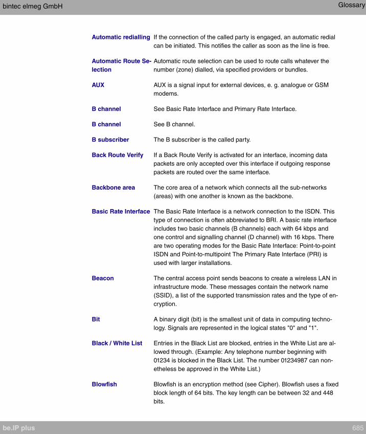
Automatic redialling If the connection of the called party is engaged, an automatic redial
can be initiated. This notifies the caller as soon as the line is free.
Automatic Route Se-
lection
Automatic route selection can be used to route calls whatever the
number (zone) dialled, via specified providers or bundles.
AUX AUX is a signal input for external devices, e. g. analogue or GSM
modems.
B channel See Basic Rate Interface and Primary Rate Interface.
B channel See B channel.
B subscriber The B subscriber is the called party.
Back Route Verify If a Back Route Verify is activated for an interface, incoming data
packets are only accepted over this interface if outgoing response
packets are routed over the same interface.
Backbone area The core area of a network which connects all the sub-networks
(areas) with one another is known as the backbone.
Basic Rate Interface The Basic Rate Interface is a network connection to the ISDN. This
type of connection is often abbreviated to BRI. A basic rate interface
includes two basic channels (B channels) each with 64 kbps and
one control and signalling channel (D channel) with 16 kbps. There
are two operating modes for the Basic Rate Interface: Point-to-point
ISDN and Point-to-multipoint The Primary Rate Interface (PRI) is
used with larger installations.
Beacon The central access point sends beacons to create a wireless LAN in
infrastructure mode. These messages contain the network name
(SSID), a list of the supported transmission rates and the type of en-
cryption.
Bit A binary digit (bit) is the smallest unit of data in computing techno-
logy. Signals are represented in the logical states "0" and "1".
Black / White List Entries in the Black List are blocked, entries in the White List are al-
lowed through. (Example: Any telephone number beginning with
01234 is blocked in the Black List. The number 01234987 can non-
etheless be approved in the White List.)
Blowfish Blowfish is an encryption method (see Cipher). Blowfish uses a fixed
block length of 64 bits. The key length can be between 32 and 448
bits.
bintec elmeg GmbH Glossary
be.IP plus 685
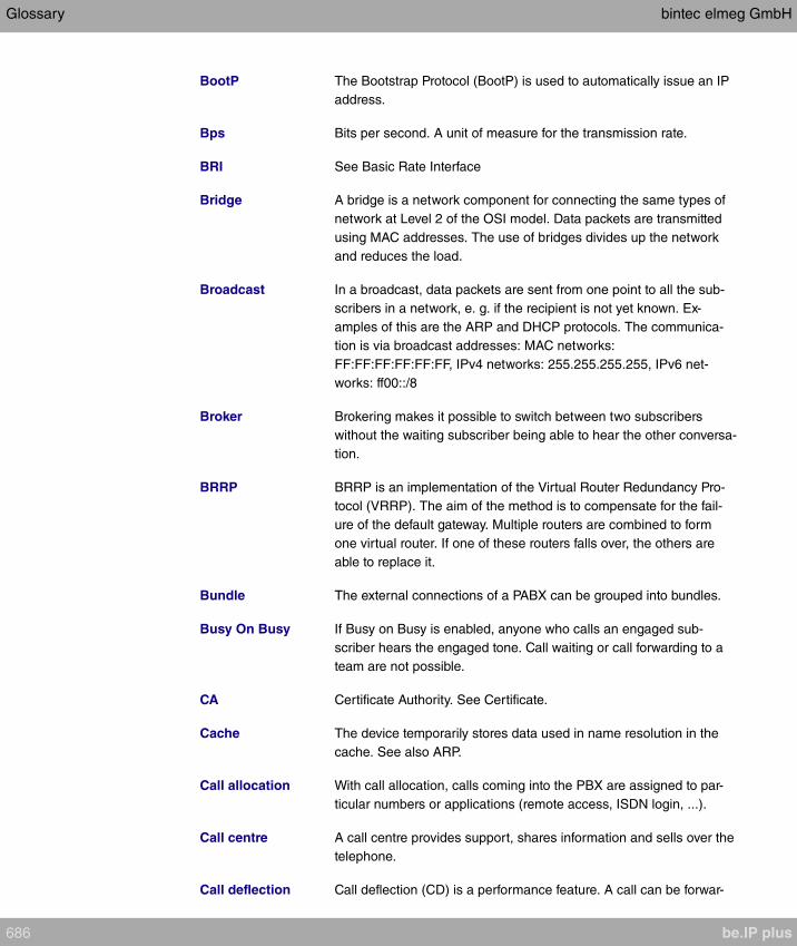
BootP The Bootstrap Protocol (BootP) is used to automatically issue an IP
address.
Bps Bits per second. A unit of measure for the transmission rate.
BRI See Basic Rate Interface
Bridge A bridge is a network component for connecting the same types of
network at Level 2 of the OSI model. Data packets are transmitted
using MAC addresses. The use of bridges divides up the network
and reduces the load.
Broadcast In a broadcast, data packets are sent from one point to all the sub-
scribers in a network, e. g. if the recipient is not yet known. Ex-
amples of this are the ARP and DHCP protocols. The communica-
tion is via broadcast addresses: MAC networks:
FF:FF:FF:FF:FF:FF, IPv4 networks: 255.255.255.255, IPv6 net-
works: ff00::/8
Broker Brokering makes it possible to switch between two subscribers
without the waiting subscriber being able to hear the other conversa-
tion.
BRRP BRRP is an implementation of the Virtual Router Redundancy Pro-
tocol (VRRP). The aim of the method is to compensate for the fail-
ure of the default gateway. Multiple routers are combined to form
one virtual router. If one of these routers falls over, the others are
able to replace it.
Bundle The external connections of a PABX can be grouped into bundles.
Busy On Busy If Busy on Busy is enabled, anyone who calls an engaged sub-
scriber hears the engaged tone. Call waiting or call forwarding to a
team are not possible.
CA Certificate Authority. See Certificate.
Cache The device temporarily stores data used in name resolution in the
cache. See also ARP.
Call allocation With call allocation, calls coming into the PBX are assigned to par-
ticular numbers or applications (remote access, ISDN login, ...).
Call centre A call centre provides support, shares information and sells over the
telephone.
Call deflection Call deflection (CD) is a performance feature. A call can be forwar-
Glossary bintec elmeg GmbH
686 be.IP plus
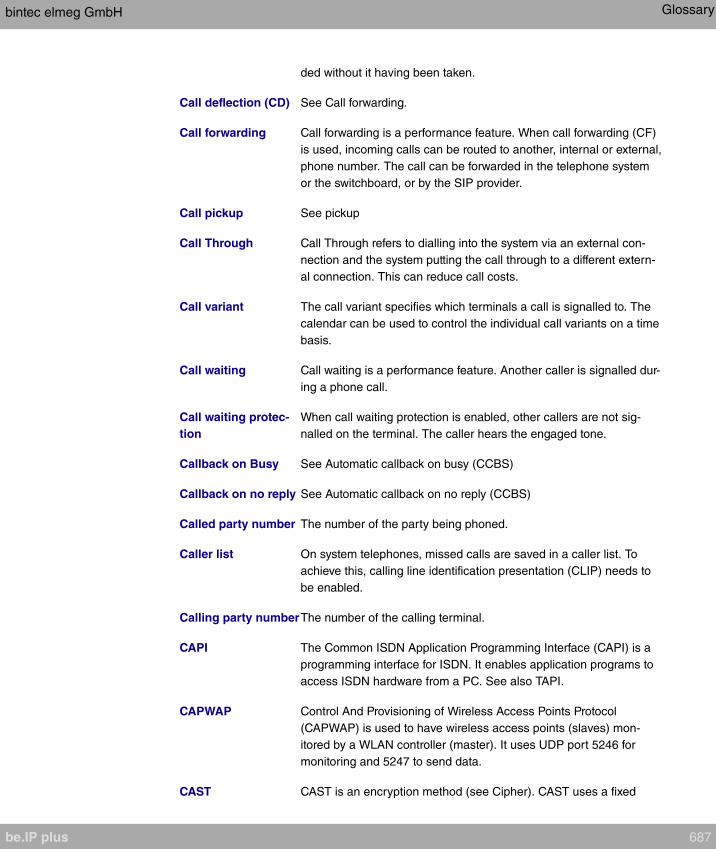
ded without it having been taken.
Call deflection (CD) See Call forwarding.
Call forwarding Call forwarding is a performance feature. When call forwarding (CF)
is used, incoming calls can be routed to another, internal or external,
phone number. The call can be forwarded in the telephone system
or the switchboard, or by the SIP provider.
Call pickup See pickup
Call Through Call Through refers to dialling into the system via an external con-
nection and the system putting the call through to a different extern-
al connection. This can reduce call costs.
Call variant The call variant specifies which terminals a call is signalled to. The
calendar can be used to control the individual call variants on a time
basis.
Call waiting Call waiting is a performance feature. Another caller is signalled dur-
ing a phone call.
Call waiting protec-
tion
When call waiting protection is enabled, other callers are not sig-
nalled on the terminal. The caller hears the engaged tone.
Callback on Busy See Automatic callback on busy (CCBS)
Callback on no reply See Automatic callback on no reply (CCBS)
Called party number The number of the party being phoned.
Caller list On system telephones, missed calls are saved in a caller list. To
achieve this, calling line identification presentation (CLIP) needs to
be enabled.
Calling party numberThe number of the calling terminal.
CAPI The Common ISDN Application Programming Interface (CAPI) is a
programming interface for ISDN. It enables application programs to
access ISDN hardware from a PC. See also TAPI.
CAPWAP Control And Provisioning of Wireless Access Points Protocol
(CAPWAP) is used to have wireless access points (slaves) mon-
itored by a WLAN controller (master). It uses UDP port 5246 for
monitoring and 5247 to send data.
CAST CAST is an encryption method (see Cipher). CAST uses a fixed
bintec elmeg GmbH Glossary
be.IP plus 687
block length of 64 bits. The key length can be between 40 and 128
bits. Alternative names are CAST-128 and CAST5.
Certificate A certificate identifies a person, an institution, a device or an applic-
ation. A public key certificate is a digital certificate and it creates a
connection between the identity and a public key. Certificates with
public keys are issued by a certification authority (CA). Certificates
that can no longer be trusted may be revoked using certificate re-
vocation lists (CRLs)
CFB Call Forwarding Busy (CFB) is a performance feature. CFB forwards
callers to a different connection if the connection of the party called
is engaged.
CFNR Call Forwarding No Reply (CFNR) is a performance feature. CFNR
forwards callers to a different connection if the call is not taken.
Channel A wireless channel is a frequency band used for wireless LAN.
Devices that send on adjacent channels disrupt one another.
Channel bundling When channels are bundled, the B channels in an ISDN connection
are combined to increase data throughput.
CHAP The Challenge Handshake Authentication Protocol (CHAP) is an au-
thentication protocol for PPP connections. As well as the standard
CHAP, Microsoft also has the variants MS-CHAPv1 and MS-
CHAPv2. You dial into a network via PPP and you authenticate
yourself with a username and password. The username and pass-
word are transmitted encrypted. See also PAP.
Cipher A block cipher is an encryption algorithm. In this encryption method,
a data block of a fixed size (normally 64 bit) is rewritten to a block of
the same size using a so-called key. The longer the key, the more
secure the algorithm.
CLID Calling Line Identification (CLID), also known as Caller ID, is used
for authentication. A caller is identified by means of his or her ISDN
extension number before the connection is established.
Client A client uses the services provided by a server. Clients are usually
workstations.
CLIP See Display caller number (CLIP / CLIR).
CLIP no Screening See also Display caller number (CLIP / CLIR). With CLIP no Screen-
ing, as well as the normal caller number, another number is also
sent, e. g. the number of the switchboard or a service number. The
Glossary bintec elmeg GmbH
688 be.IP plus
normal number can also be suppressed using CLIP, so that the
party called only sees the other number.
CLIP off Hook See Display caller number (CLIP / CLIR).
CLIR See Display caller number (CLIP / CLIR).
Code procedure A sequence (code procedure) (consisting of 0 - 9, *, # and R) can be
entered on the telephone keypad in order to access the PBX's func-
tions.
COLP See Display called party number (COLP / COLR).
COLP no Screening See also Display called party number (COLP / COLR). With COLP
no Screening, as well as the normal caller number, another number
is also sent, e. g. the number of the switchboard or a service num-
ber. The normal number can also be suppressed using COLP, so
that the party called only sees the other number.
COLR See Display called party number (COLP / COLR).
Conference call With a conference call, multiple internal subscribers can speak to
one another on the phone at the same time.
Configuration The configuration refers to all of a device's settings. It is stored in-
ternally, in MIB tables. This data can be backed up, loaded and de-
leted externally. The configuration is edited using the HTTP(S) user
interface, an SNMP client or connected telephones.
CoS The term Class of Service (CoS) means different things depending
on the area in which it is applied. In telecommunications CoS refers
to the permission class assigned to the user. The permission class
defines the user's rights, e. g. exchange access right, features that
can be used, access to applications, ... In network technology CoS
refers to the classification of certain services as per IEEE 802.1p.
CoS enables priorities to be set in a targeted way, while Quality of
Service (QoS) is used to set up explicit bandwidth guarantees or re-
strictions. Data packets are classified using a DSCP (Differentiated
Services Code Point) value.
CRC Cyclic Redundancy Check (CRC) is a method of detecting errors in
the data transmission.
CRL See Certificate.
D channel See Basic Rate Interface and Primary Rate Interface.
bintec elmeg GmbH Glossary
be.IP plus 689

Daemon A daemon refers to a program that runs in the background and
provides certain services.
Data compression Data compression is a method of reducing the data volume transmit-
ted. See STAC and MPPC.
Datagram A datagram is a self-contained data entity with user and control
data. It generally stands for the terms data frame, data packet and
data segment.
DCN DCN stands for data communication network.
DDI DDI stands for Direct Dial In. See Point-to-point ISDN access and
Direct dial-in (VoIP).
Dead Peer Detection In IPSec, Dead Peer Detection is used to identify IKE peers that can
no longer be accessed.
DECT Digital Enhanced Cordless Telecommunications (DECT) is a stand-
ard for cordless telephones and wireless PABX systems.
Default gateway All the data traffic which is not intended for one's own network is
sent to the default gateway (default router).
Default route See Standard route
Default route The default route is used when no other suitable route is available.
Default router See Default gateway.
Deffie-Hellman Diffie-Hellman is a public key algorithm for negotiating and estab-
lishing keys. Because data is neither encrypted nor signed, the
method is only secure if the connecting partners authenticate them-
selves using other mechanisms such as RSA and DSA.
Denial-Of-Service At-
tack
In a Denial-Of-Service Attack (DoS), a network component is
flooded with queries so that it becomes totally overloaded. As a res-
ult, the system or a particular service can no longer function.
DES The Data Encryption Standard (DES) is an encryption method (see
Cipher). DES uses a fixed block length of 64 bits. The key length is
56 bits. Triple DES or 3DES is based on using DES three times
(three different, independent keys).
DHCP The Dynamic Host Configuration Protocol (DHCP) allows IP ad-
dresses to be assigned dynamically. A DHCP server allocates each
client in a network an IP address from a defined address pool. The
Glossary bintec elmeg GmbH
690 be.IP plus
clients need to be configured accordingly.
Dial preparation Dial preparation describes the entering of the telephone number be-
fore initiating the call, e. g. by lifting the receiver.
Dialling control See Black / White List.
Dialup connection When required, a dialup connection is established by dialling a
phone number, in contrast to a fixed connection (see Leased line)
which is permanently enabled.
Digital Digital signals are used to transmit data. They are less susceptible
to errors than analogue signals.
DIME Desktop Internetworking Management Environment (DIME) is used
to configure and monitor gateways.
Direct call If the direct call function is set up, the user merely has to lift the tele-
phone receiver to, after a short wait, automatically get a connection
to a particular phone number.
Direct dial exception See Point-to-point ISDN access and Direct dial-in (VoIP).
Direct dial-in (VoIP) Direct dial-in is a VoIP connection that is also known as point-
to-point. It is used to connect a PBX. A main phone number and a
number block are issued. Each of the numbers in the number block
is called a direct dial exception. (Example: Main number 1234, num-
ber block: 1 - 99, numbers of the individual extensions: 1234-1,
1234-2, 1234-3, …)
Direct dialling range See number block in Point-to-point ISDN access and Direct dial-in
(VoIP)
DISA DISA - Direct Inward System Access A call, after it has been taken
by the PBX, is automatically forwarded after a code has been
entered. In the PBX, this code is assigned to an internal telephone
number.
Display called party
number (COLP /
COLR).
Connected Line Identification Presentation (COLP) is used to send
the phone number of the called party (B phone number) to the
caller. Connected Line Identification Restriction (COLR) is used to
suppress the transmission of the phone number of the called party
to the caller.
Display caller num-
ber (CLIP / CLIR).
Calling Line Identification Presentation (CLIP) is used to send the
caller's phone number (A phone number) to the called party. CLIP
off Hook sends the phone number of the caller waiting. Calling Line
bintec elmeg GmbH Glossary
be.IP plus 691
Identification Restriction (CLIR) is used to suppress the transmission
of the phone number of the caller to the called party.
DNS The Domain Name System (DNS) is used to convert the domain
name (e. g. www.example.org) to an IP address (name resolution).
Do not disturb See Station guarding.
Domain A domain is a contiguous sub-set of the DNS (e. g. example.org).
Door intercom A door intercom is mounted on entrances, and may be part of a
PBX.
Downstream The gateway receives the data from a higher-level network and for-
wards it to its connected network.
DSA The Digital Signature Algorithm (DSA) is used to create digital sig-
natures and encrypt data packets. Signatures can be used to verify
changes made to the information in the data packet. DSA is used for
public-key cryptography (IPSec). See also RSA. Key generation is
quicker with DSA than with RSA, but key processing is slower.
DSCP Data packets can be marked with a Differentiated Services Code-
point (DSCP). DSCP values classify data packets in such a way that
important packets can be routed through the network more quickly.
See also QoS.
DSL modem See Modem.
DSP A digital signal processor (DSP) converts analogue, ISDN and VoIP
signals to one another. So, e. g., analogue terminals can also be
used on an SIP connection.
DSS1 Digital Subscriber Signalling System No. 1 (DSS1) is a signalling
protocol for the D channel in the ISDN. It is also known as Euro
ISDN.
DTIM A Delivery Traffic Indication Message informs the clients that multic-
ast or broadcast data is available at the access point.
DTMF See Multifrequency code dialling method.
DTMF Inband / Out-
band
See also Multifrequency code dialling method. With inband, the
DTMF signal is transmitted in the voice band (G.711) With outband,
the DTMF signal is transmitted as specified in RFC 2833.
Dynamic IP address In contrast to a static IP address, a dynamic IP address is assigned
Glossary bintec elmeg GmbH
692 be.IP plus
temporarily by DHCP. Network components such as the web server
or printer usually have static IP address, while clients such as note-
books or workstations usually have dynamic IP addresses.
DynDNS A DynDNS provider can be used to link a domain name with a dy-
namically changing IP address.
Encapsulation Encapsulation of data packets is a particular protocol to transmit the
data packets in a network. See also VPN.
Encryption Refers to the encryption of data, e.g. using MPPE.
Engaged when busy See Busy on Busy.
ESP Encapsulating Security Payload (ESP) is a protocol for IPSec. It
uses protocol number 50 and supports data encryption and authen-
tication.
Ethernet Ethernet is a specification for cable data networks. Ethernet works
on the first and second layer of the OSI model.
Euro ISDN Standard ISDN in Europe, based on the DSS1 signalling protocol.
Eurofile transfer Eurofile transfer (EFT) is a protocol for sharing files over ISDN.
Exchange access
right
The telephone system distinguishes between the following ex-
change access rights: Unlimited: Any international, national or in-
ternal connection is permitted. National long-distance calls: Only do-
mestic connections may be established - i. e. dialling any number
that begins with 0 but not with 00. Incoming external calls can be re-
ceived without restrictions. Locality: Only connections to the same
area code may be established. So the number may not begin with a
0. Incoming external calls can be received without restrictions. In-
coming: Only connections to other terminals in the telephone system
may be established. Incoming external calls can be received without
restrictions. Internal: Only connections within the telephone system
are permitted.
Extension In PBX systems, an extension refers to the terminal connected to
the system.
Extension number See Point-to-point ISDN access and Direct dial-in (VoIP).
Extension number
block
See Point-to-point ISDN access and Direct dial-in (VoIP).
Extension numbers See Extension number block in Point-to-point ISDN access.
bintec elmeg GmbH Glossary
be.IP plus 693

range
Fax Fax is used to send text, graphics and documents over the phone
network. A distinction is drawn between Group 3 fax machines for
the analogue network (transmission rate: 9.6 or 14,4 kbit/s) and
Group 4 fax machines for ISDN (transmission rate: 64 kbit/s). To
connect Group 3 fax machines to ISDN, a terminal adapter or a suit-
able PBX is required.
Filter A filter comprises a number of criteria (e.g. protocol, port number,
source and destination address). If these criteria match a data pack-
et, the data packet can be subjected to a particular action (forward,
reject, ...). This creates a filter rule.
Filter rule A rule that defines which data packets should or should not be
transmitted by the gateway.
Firmware The firmware (system software) is programming code that is per-
manently embedded in the device. It provides the device's functions.
Flash key The flash key on a telephone is the R button. The key interrupts the
line briefly to start certain functions such as inquiries.
Follow-me Follow-me is a performance feature. This function can be used to
route incoming calls from a different extension to one's own termin-
al.
Fragmentation If the overall length of the data packet is greater than the Maximum
Transmission Unit (MTU) of the network interface, the data packet
has to be broken down into multiple physical data blocks using IP
fragmentation. The reverse process is known as reassembly.
Frame A data frame is an information unit (Protocol Data Unit) in the data
link layer in the OSI model.
Frame relay Frame relay is a data transmission technology and upgrade of X.25
(smaller packets, less error checking). Frame relay is primarily used
for GSM networks.
FTP The File Transfer Protocol (FTP) regulates data transmission in IP
networks. It regulates the exchange between FTP server and client.
Full-duplex With full-duplex, data can be sent and received simultaneously over
a line.
Function keys Function keys are special keys on system telephones which can be
assigned phone numbers or functions.
Glossary bintec elmeg GmbH
694 be.IP plus
FXO Foreign Exchange Office (FXO) refers to the connection to the ana-
logue terminal. See also FXS.
FXS Foreign Exchange Station (FXS) refers to the analogue connection
to the connection socket or PBX. See also FXO.
G.711 G.711 is an audio codec. Audio signals from the frequency range
between 300 Hz and 3400 Hz are passed with a sampling rate of 8
kHz. At a data transmission rate of 64 kbit/s, the codec achieves ex-
cellent voice quality (MOS value: 4.4). The A-law quantisation meth-
od is used in Europe, and the µ-law method in the USA.
G.722 G.722 is an audio codec. Audio signals from the frequency range
between 50 Hz and 7000 Hz are passed with a sampling rate of 16
kHz. At a data transmission rate of 64 kbit/s, the codec achieves
outstanding voice quality (MOS value: 4.5).
G.726 G.726 is an audio codec. Audio signals from the frequency range
between 200 Hz and 3400 Hz are passed with a sampling rate of 8
kHz. The codec achieves an acceptable voice quality. MOS value:
3.7 (16 kbit/s), 3.8 (24 kbit/s), 3.9 (32 kbit/s), 4.2 (40 kbit/s). There
are two different coding methods: I.366 and X.420
G.729 G.729 is an audio codec. Audio signals from the frequency range
between 300 Hz and 2400 Hz are passed with a sampling rate of 16
kHz. At a data transmission rate of 8 kbit/s, the codec achieves an
acceptable voice quality (MOS value: 3.9).
G.991.1 Data transmission recommendation for HDSL.
G.991.2 Data transmission recommendation for SHDSL.
G.992.1 Data transmission recommendation for ADSL. There are two coun-
try-specific versions: G.992.1 Annex A and G.992.1 Annex B. Data
transfer rates: 12 Mbit/s (downstream), 1.3 Mbit/s (upstream)
G.992.2 Data transmission recommendation for ADSL (G.LITE / ADSL-Lite).
There are two versions: G.992.2 Annex A and G.992.2 Annex B.
Data transfer rates: 12 Mbit/s (downstream), 1.3 Mbit/s (upstream)
G.992.3 Data transmission recommendation for xDSL2. There are three vari-
ants: G.992.3 Annex A/B (G.DMT to ADSL2) with data transmission
rates of 12 Mbit/s in the downstream and 1.0 Mbit/s in the upstream,
G.992.3 Annex L (RE-ADSL2) with data transmission rates of 5
Mbit/s in the downstream and 0.8 Mbit/s in the upstream and
G.992.3 Annex M (ADSL2) with data transmission rates of 12 Mbit/s
bintec elmeg GmbH Glossary
be.IP plus 695
in the downstream and 2.5 Mbit/s in the upstream.
G.992.4 Data transmission recommendation for ADSL2 with Annex A/B.
Data transmission rates: 12 Mbit/s (downstream), 1.0 Mbit/s
(upstream)
G.992.5 Data transmission recommendation for xDSL2+. There are three
variants: G.992.5 Annex A/B (ADSL2+) with data transmission rates
of 25 Mbit/s in the downstream and 1.0 Mbit/s in the upstream,
G.992.5 Annex L (RE-ADSL2+) with data transmission rates of 25
Mbit/s in the downstream and 1.0 Mbit/s in the upstream and
G.992.5 Annex M (ADSL2+) with data transmission rates of 25 Mbit/
s in the downstream and 3.5 Mbit/s in the upstream.
G.993.1 Data transmission recommendation for VDSL. Data transmission
rates: 52 Mbit/s (downstream), 16 Mbit/s (upstream)
G.993.2 Data transmission recommendation for VDSL2. Data transmission
rates: 200 Mbit/s (downstream), 200 Mbit/s (upstream)
G.DMT See F.992.1.
G.Lite See F.992.2.
G.SHDSL See G.991.2.
Gateway The gateway is a network component for connecting different types
of network.
GPRS General Packet Radio Service (GPRS) is the name for the packet-
oriented service for transmitting data in GSM networks.
GRE Generic Routing Encapsulation (GRE) is a network protocol for en-
capsulating other protocols so that they can be transported via the
Internet Protocol (IP) in the form of a tunnel (VPN). GRE uses pro-
tocol number 47.
GSM The Global System for Mobile Communications (GSM), also known
as 2G, is a mobile communications standard. It achieves, along with
GPRS, a specified max. data transmission rate of 171.2 kbit/s.
Half-duplex With half-duplex, data can only be sent and received back-to-back
over a line.
Hands-free calling With hands-free calling, calls can be made without lifting the receiv-
er. Other people in the room can participate in the conversation us-
ing a microphone and loudspeakers.
Glossary bintec elmeg GmbH
696 be.IP plus
Hash To ensure data integrity, the information needs to be protected from
unauthorised manipulation while it is being transmitted. To ensure
that this happens, every item of communication received has to
match the information originally sent. Therefore erratic mathematical
value functions (hash functions) are used to calculate checksums
(hash values). These are encrypted and sent as a digital signature
with the message. The recipient, in turn, checks the signature before
opening the packet. If the signature and, thus, the content of the
data packet has changed, the packet is discarded. The hash al-
gorithms used most frequently are Message Digest Version 5 (MD5)
and Secure Hash Algorithm (SHA1).
HDSL High Data Rate Digital Subscriber Line. See DSL.
Heartbeat A network's subscribers use heartbeats to signal that they are ready
to receive.
Hold A telephone call is put on hold without breaking the connection
(inquiry/brokering). A distinction is drawn between holding the con-
nection in the PBX (holding in the system) and holding in the switch-
board or by the SIP provider.
Hold for enquiry With hold for enquiry, the phone call with the first party is held while
one conducts a second call.
Hop Hop is the term for the connection from one network node to the
next.
Host A host is a computer system that provides its services to the net-
work.
Host name The domain name of a host. See DNS.
Host route A host route is the name for the route to a single host.
Hotspot A hotspot is a public internet access point via WLAN or wired Ether-
net.
HSDPA High Speed Downlink Packet Access (HSDPA, 3.5G, 3G+ or UMTS
broadband) is a data transmission method in the UMTS mobile com-
munications standard.
HTTP The HyperText Transfer Protocol (HTTP) is a protocol for transmit-
ting HTML pages (web pages) between server and client. By default
it uses port 80.
HTTPS The HyperText Transfer Protocol Secure (HTTPS) is a protocol
bintec elmeg GmbH Glossary
be.IP plus 697

which protects against eavesdropping when transmitting HTML
pages (web pages) between server and client. HTTPS is schematic-
ally identical to HTTP. SSL / TLS is used for additional data encryp-
tion. The standard port for HTTPS connections is 443.
Hyperchannel With a hyperchannel, multiple subscribers have access to the trans-
mission medium. A subscriber can only transmit their data if no oth-
er subscriber is using the medium. A hyperchannel network is
mainly used for short-range operation with top data rates.
IAE IAE refers to the standard socket (ISDN connection unit) to which
ISDN terminals are connected.
ICMP The Internet Control Message Protocol (ICMP) is used to exchange
information and error messages over IPv4. The version ICMPv6 ex-
ists for IPv6.
IGMP The Internet Group Management Protocol (IGMP) is used in IPv4
networks to organise multicast groups.
IKE The Internet Key Exchange Protocol (IKE) is used for automatic key
management with IPSec connections. The IKE process runs in two
phases. During phase 1, the IKE subscribers authenticate them-
selves to one another and establish a secure channel. In phase 2,
the two IPSec subscribers negotiate the SAs. There are two ver-
sions of the IKE mechanism.
Infrastructure net-
work
In an infrastructure network the individual terminals (clients) form a
wireless LAN via a central access point. This central access point
may also be an agent in other networks.
Internal call tone The internal call tone on a PBX is used to differentiate between in-
ternal and external calls.
Internal telephone
numbers
Internal phone numbers are used for calls within the PBX.
IP The Internet Protocol (IP) is a network protocol and it is the basis for
the Internet. It works on the network layer of the OSI model. The
TCP and UDP protocols are based on IP. There are two versions,
Internet Protocol version 4 (IPv4) and Internet Protocol version 6
(IPv6).
IP address IP addresses are used to navigate in an IP network, to unambigu-
ously identify the source and destination. IPv4 addresses consist of
32 bits, IPv6 addresses of 128 bits. So, with IPv4 232, i.e.
Glossary bintec elmeg GmbH
698 be.IP plus
4.294.967.296 addresses can be represented, with IPv6 2128 =
340.282.366.920.938.463.463.374.607.431.768.211.456 addresses.
Dotted decimal notation, e. g. 192.168.0.250, is used for IPv4.
Hexadecimal notation, e. g. 2001:db8:85a3::8a2e:370:7344, is used
for IPv6. See also netmask.
IPCP The Internet Protocol Control Protocol (IPCP) is used, in a similar
way to DHCP, to configure a host with an IP address, gateway and
DNS server, when a PPP network connection is being used. With
the extension Robust Header Compression over PPP, the header
can be compressed for faster data transmission. Similarly, in IPv6
networks, the functionality is provided by the Internet Protocol ver-
sion 6 Control Protocol (IPV6CP).
IPSec IPSec (Internet Protocol Security) is a network protocol for encapsu-
lating other protocols so that they can be transported via the Internet
Protocol (IP) in the form of a tunnel (VPN). The protocol number for
IPSec depends on the protocol used. The Authentification Header
(AH) uses protocol number 51, while the Encapsulating Security
Payload (ESP) uses number 50.
IPv6 See IP.
ISDN Integrated Services Digital Network (ISDN) is a data transmission
standard that includes telephony, fax and data transmission. There
are two ISDN connection variants: Basic Rate Interface and Primary
Rate Interface.
ISDN address The ISDN address of an ISDN device comprises an ISDN number
followed by other numbers that relate to the specific terminal.
ISDN login The ISDN login is used to remotely configure the device via SNMP.
To do so, it needs to have a configured ISDN or wireless connec-
tion.
ISDN number The ISDN number is the network address of the ISDN interface.
ISDN router See Router.
ISDN-BRI See BRI.
ISDN-Intern-
al/External
Alternative name for the So bus.
ISDN-PRI See PRI.
ISP Internet Service Providers (ISPs) supply technical services for using
bintec elmeg GmbH Glossary
be.IP plus 699
the Internet.
ITU The International Telecommunication Union (ITU) coordinates the
setting up and operating of telecommunications networks and ser-
vices.
Keepalive Keepalive packets are used to check that the communication part-
ner can be contacted.
Keepalive Keepalive is a mechanism for maintaining the network connection
and for checking that the communication partner can be reached.
Specific packets are usually sent to the network for this purpose.
Keypad The keypad protocol (network direct) is used to access and manage
performance features provided by the switchboard.
L2TP The Layer 2 Tunneling Protocol (L2TP) is a network protocol for en-
capsulating other protocols so that they can be transported via the
Internet Protocol (IP) in the form of a tunnel (VPN). By default, L2TP
uses protocol number 1701. The architecture in an L2TP network
consists of an L2TP access concentrator (LAC) which may also be
permanently integrated into the client, and the L2TP network server
(LNS). The LAC establishes the connections to the LNS and man-
ages them. The authorisation is regulated using a network access
server (NAS), which can be implemented in the LAC or LNS. The
LNS is responsible for routing and controlling the packets received
from the LAC. The user data itself is exchanged unencrypted, while
control messages for maintaining the accessibility of the tunnel end-
points are transmitted securely.
LAC See L2TP.
LAN A Local Area Network (LAN) refers to a network that is geographic-
ally very limited and normally spans one building or a company head
office.
Layer A layer refers to a layer in the OSI model.
LCP The Link Control Protocol (LCP) is used in PPP connections to auto-
matically negotiate encapsulation, process limits for varying packet
sizes, authenticate the connection partner, determine faulty links,
identify connection faults and terminate the connection.
LDAP The Lightweight Directory Access Protocol (LDAP) regulates the
communication between a client and the directory server. LDAP is
used for sharing and updating directories, e. g. a phone book.
Glossary bintec elmeg GmbH
700 be.IP plus
Lease time The lease time refers to the validity period of a dynamic IP address
that a client has been given by a DHCP server.
Leased line See Leased line
Leased line A leased line is a permanent connection of two communication part-
ners via telecommunications network.
Line access author-
isation
See Exchange access right.
LLC The Link Layer Control (LLC) regulates the media allocation at MAC
level.
LNS See L2TP.
Load balancing With load balancing, data is sent via different interfaces in order to
increase the overall bandwidth available. In contrast to Multilink,
load balancing also functions with accounts with different providers.
Loopback In a loopback switch the sender and recipient are identical.
LTE Long Term Evolution (LTE), also known as 4G, is a mobile commu-
nications standard with a standardised maximum data transmission
rate of 300 Mbit/s.
MAC address The Media Access Control address (MAC address) is the hardware
address of the network adapter and is used to identify the device at
the hardware level.
Main Mode When establishing an IPSec connection, main mode is used to im-
plement a phase 1 exchange by setting up a secure channel. See
also Aggressive mode.
Man-in-the-Middle at-
tack
In a Man-in-the-Middle attack, the attacker is physically or logically
between the two communication partners and so is able to view, and
even manipulate, the data traffic.
MD5 Message Digest Algorithm 5 (MD5) is a hash function that generates
a 128 bit hash value (checksum). See also Hash.
Media gateway A media gateway converts the network type of digital voice, audio or
image information. For example, the signals from an ISDN network
can be converted to an IP network.
Metric The metric is a measure for the properties of the route. The fastest
route has the lowest metric (costs). Simplified, this is connecting
bintec elmeg GmbH Glossary
be.IP plus 701
with the smallest number of node points (routers).
MFC See Multifrequency code dialling method.
MFV See Multifrequency code dialling method.
MIB The Management Information Base (MIB) describes the data that
can be queried or modified via a network management protocol (e.
g. SNMP). The MIB is a database that describes all the devices and
functions in the network.
MLP The Multicast Listener Discovery (MLD) is used in IPv6 networks to
organise multicast groups.
Mobile subscriber If the mobile subscriber is enabled, an external telephone, e. g. a
mobile phone can be called in parallel (parallel calling). The sys-
tem's functions, e. g. callback, can also be used externally. For
these functions, the external telephone's star key is interpreted as
the R key.
Modem A modem is an electronic device that converts digital signals to fre-
quency signals in order to distribute data in a wired or wireless net-
work.
MOH See Music on hold.
MPDU The MAC Protocol Data Unit (MPDU) refers to a data packet, includ-
ing management frames and fragmented MSDUs, exchanged wire-
lessly.
MPPC Microsoft Point-to-Point Compression (MPPC) is a method of data
compression.
MPPE Microsoft Point-To-Point Encryption (MPPE) is used to encrypt data
transmitted via PPP. It was developed by Microsoft and Cisco and
specified as RFC 3078.
MS-CHAP The Microsoft Challenge Handshake Authentication Protocol
(MS-CHAP) is a method of authentication. MS-CHAPv1 is intended
for authenticating DCN connections and is largely the same as the
standard CHAP. MS-CHAPv2 is an authentication method for PPTP
connections (VPN).
MSDU A MAC Service Data Unit (MSDU) is a data packet that is ex-
changed at LLC level.
MSN See Multiple subscriber number
Glossary bintec elmeg GmbH
702 be.IP plus
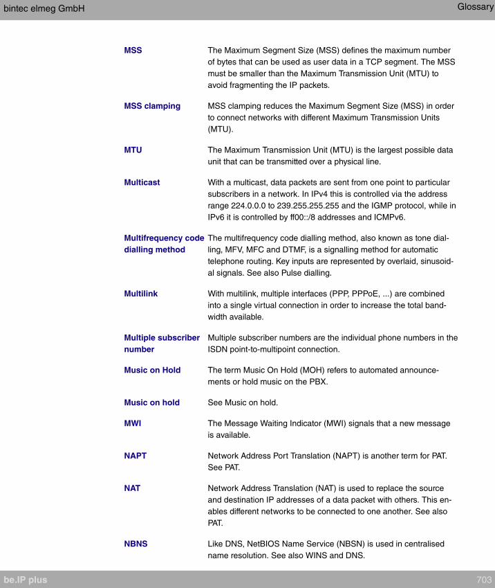
MSS The Maximum Segment Size (MSS) defines the maximum number
of bytes that can be used as user data in a TCP segment. The MSS
must be smaller than the Maximum Transmission Unit (MTU) to
avoid fragmenting the IP packets.
MSS clamping MSS clamping reduces the Maximum Segment Size (MSS) in order
to connect networks with different Maximum Transmission Units
(MTU).
MTU The Maximum Transmission Unit (MTU) is the largest possible data
unit that can be transmitted over a physical line.
Multicast With a multicast, data packets are sent from one point to particular
subscribers in a network. In IPv4 this is controlled via the address
range 224.0.0.0 to 239.255.255.255 and the IGMP protocol, while in
IPv6 it is controlled by ff00::/8 addresses and ICMPv6.
Multifrequency code
dialling method
The multifrequency code dialling method, also known as tone dial-
ling, MFV, MFC and DTMF, is a signalling method for automatic
telephone routing. Key inputs are represented by overlaid, sinusoid-
al signals. See also Pulse dialling.
Multilink With multilink, multiple interfaces (PPP, PPPoE, ...) are combined
into a single virtual connection in order to increase the total band-
width available.
Multiple subscriber
number
Multiple subscriber numbers are the individual phone numbers in the
ISDN point-to-multipoint connection.
Music on Hold The term Music On Hold (MOH) refers to automated announce-
ments or hold music on the PBX.
Music on hold See Music on hold.
MWI The Message Waiting Indicator (MWI) signals that a new message
is available.
NAPT Network Address Port Translation (NAPT) is another term for PAT.
See PAT.
NAT Network Address Translation (NAT) is used to replace the source
and destination IP addresses of a data packet with others. This en-
ables different networks to be connected to one another. See also
PAT.
NBNS Like DNS, NetBIOS Name Service (NBSN) is used in centralised
name resolution. See also WINS and DNS.
bintec elmeg GmbH Glossary
be.IP plus 703

Netmask With IPv4 in connection with the IP address, the netmask, also net-
work mask and subnet mask, defines the network by dividing the IP
address into network and device parts and thus determining which
addresses need to be routed. Example of a netmask:
255.255.255.0. With IPv6 one refers to prefix length.
Network address A network address is the address of the network as a whole. The
network mask and prefix length divide the IP address into the net-
work address and host address (device address). Example of a net-
work address: 192.168.0.250/24
Network direct See Keypad.
Network route The network route refers to the route to a particular network.
Network termination Network termination (NT) refers to a connection or operating type. A
terminal is given access to a communication network at the NT inter-
face (connection socket). The connector is called a TAE with an
analogue connection, an NTBA with the basic ISDN connection, and
NTPMGF with the ISDN Primary Rate Interface. In the NT operation,
the gateway is connected to the PABX's external S0 and is an ex-
ternal exchange connection for it. See also TE.
NT See Network termination.
NTBA See Network termination.
NTP The Network Time Protocol (NTP) is used to synchronise the time of
day.
NTPMGF See Network termination.
OAM OAM is a service for monitoring ATM connections.
Open hold for en-
quiry
With open hold for enquiry, a call is put on hold and either party can
then resume it once more.
OSI model The OSI model divides the flow of communication between the
physical medium and the user level into layers. The requirements at
each layer are met by relevant protocols.
OSPF OSPF is a dynamic routing protocol which is usually used in larger
network installations as an alternative to RIP.
PABX Private Automatic Branch Exchange (PABX) is another expression
for a telephone system.
Glossary bintec elmeg GmbH
704 be.IP plus

PABX PABX is another term for a telephone system.
PAP The Password Authentication Protocol (PAP) is an authentication
method for connections via PPP. Unlike with CHAP, the username
and password are not sent encrypted.
Parallel call See Mobile subscriber.
Park When a call is parked, the connection is held even if the receiver of
the terminal involved is replaced or the cable connection is cut off.
PAT Port and Address Translation (NAT) is used to replace the source
and destination IP addresses and source and destination ports of a
data packet with others. This enables different networks to be con-
nected to one another. See also NAT.
PBX Private Branch Exchange (PABX) is another expression for a tele-
phone system.
PDM See Pulse dialling
Peer A peer is the endpoint of a communication in the network.
Phase 1/2 See IKE.
Pick-up With pick-up, calls can be received using code procedures on an in-
ternal terminal that is not part of active call allocation.
PIM The Protocol Independent Multicast (PIM) enables the dynamic rout-
ing of multicast packets on the Internet.
PIN A personal identification number (PIN) can be used to authenticate
oneself on the device so that one can use the device's functions.
Ping Ping is a diagnostic tool that can be used to check whether a partic-
ular host in an IP network can be contacted. A measurement is
taken of the time interval between sending a data packet (ICMP(v6)
echo request packet) and receiving a response packet sent back im-
mediately. This enables the connection quality to be determined.
PKCS The Public-Key Cryptography Standards (PKCS) are standards for
public key cryptography. The PKCS are designed for binary and AS-
CII data and are compatible with the X.509 standard. The public
standards are PKCS #1, #3, #5, #7, #8, #9, #10, #11, #12 and #15.
PKCS #10 describes the syntax for certification inquiries.
PKI A public key infrastructure (PKI) is used to issue, distribute and veri-
bintec elmeg GmbH Glossary
be.IP plus 705
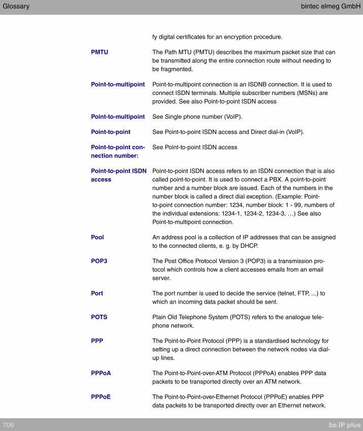
fy digital certificates for an encryption procedure.
PMTU The Path MTU (PMTU) describes the maximum packet size that can
be transmitted along the entire connection route without needing to
be fragmented.
Point-to-multipoint Point-to-multipoint connection is an ISDNB connection. It is used to
connect ISDN terminals. Multiple subscriber numbers (MSNs) are
provided. See also Point-to-point ISDN access
Point-to-multipoint See Single phone number (VoIP).
Point-to-point See Point-to-point ISDN access and Direct dial-in (VoIP).
Point-to-point con-
nection number:
See Point-to-point ISDN access
Point-to-point ISDN
access
Point-to-point ISDN access refers to an ISDN connection that is also
called point-to-point. It is used to connect a PBX. A point-to-point
number and a number block are issued. Each of the numbers in the
number block is called a direct dial exception. (Example: Point-
to-point connection number: 1234, number block: 1 - 99, numbers of
the individual extensions: 1234-1, 1234-2, 1234-3, …) See also
Point-to-multipoint connection.
Pool An address pool is a collection of IP addresses that can be assigned
to the connected clients, e. g. by DHCP.
POP3 The Post Office Protocol Version 3 (POP3) is a transmission pro-
tocol which controls how a client accesses emails from an email
server.
Port The port number is used to decide the service (telnet, FTP, ...) to
which an incoming data packet should be sent.
POTS Plain Old Telephone System (POTS) refers to the analogue tele-
phone network.
PPP The Point-to-Point Protocol (PPP) is a standardised technology for
setting up a direct connection between the network nodes via dial-
up lines.
PPPoA The Point-to-Point-over-ATM Protocol (PPPoA) enables PPP data
packets to be transported directly over an ATM network.
PPPoE The Point-to-Point-over-Ethernet Protocol (PPPoE) enables PPP
data packets to be transported directly over an Ethernet network.
Glossary bintec elmeg GmbH
706 be.IP plus

PPTP The Point-to-Point Tunneling Protocol (PPTP) is a network protocol
for encapsulating other protocols so that they can be transported via
the Internet Protocol (IP) in the form of a tunnel (VPN). PPTP uses
protocol number 1723. The PPTP architecture is divided into two lo-
gical systems. The PPTP Access Concentrator (PAC) and the PPTP
Network Server (PNS). The PAC is usually integrated into the Win-
dows client. It establishes the connection to the PNS and manages
it. The PNS is responsible for routing and controlling the packets re-
ceived by the PNS.
Pre-shared key A pre-shared key (PSK) is a key for an encryption procedure. The
parties shared the key's value beforehand.
Prefix See Network address
Prefix delegation In IPv6 networks, prefix delegation is used to assign the network ad-
dress (prefix) to the router.
Prefix length See netmask.
PRI See Primary Rate Interface.
Primary Rate Inter-
face
The Primary Rate Interface is a network connection to the ISDN.
This type of connection is often also called a PRI or S2Minterface. A
Primary Rate Interface offers 30 user channels (B channels), each
with 64 kbits/s, in Europe and 23 in the USA, one control channel (D
channel) with 64 kbits/s and one synchronisation channel with 64
kbits/s in Europe and 8 64 kbits/s in the USA. See also Basic Rate
Interface.
Proposal When an IPSec connection is being established, the initiator of the
connection makes proposals with relation to the authentication and
encryption methods to be used.
Protocol Protocols regulate the flow of a data communication on different
levels of the OSI model. Protocols control addressing, coding, au-
thentication, formatting, etc. Examples: Ethernet, IP, TCP, HTTP
Proxy A proxy is a network component. The proxy is an agent. It routes a
query from the source with its own IP address to the destination.
Pulse dialling Pulse dialling is a signalling method for automated telephone rout-
ing. Key inputs are represented by a defined number of dc pulses.
See also Multifrequency code dialling method (MF).
PVID The Port VLAN Identifier (PVID) is the standard VLAN ID for the port
concerned. A packet that reaches this port without a VLAN tag is as-
bintec elmeg GmbH Glossary
be.IP plus 707

signed this ID.
Q-SIG Q-Interface Signalling Protocol (Q-SIG) is an ISDN-based signalling
protocol for linking PABX systems.
QoS Quality of Service (QoS) describes the properties of the communica-
tion service. It is defined using bandwidth, delay, packet losses and
jitter. To transmit time-critical data packets for VoIP or video stream-
ing as quickly as possible, QoS is used to sort all the data packets
into groups and forward them on in the network either more quickly
or slowly, depending on their priority.
Queue The data packets accumulate in a queue before they are sent.
RADIUS Remote Authentication Dial-In User Service (RADIUS) is a client-
server protocol for authenticating, authorising and accounting for
users with dial-in connections. The RADIUS server authenticates
the client, e. g. by checking the username and password. See also
TACACS+.
RE-ADSL2 See G.992.5.
Real Time Jitter Con-
trol
Real Time Jitter Control is used, where necessary, to reduce the
size of data packets during a telephone conversation so that voice
packets are not blocked.
Registrar The SIP server (registrar) needs to be used in case the subscribers
to a VoIP call are not using static IP addresses The SIP server re-
gisters the clients' IP addresses and sends this data to the SIP
proxy, which connects the calls. The SIP proxy and SIP registrar are
usually identical.
Reject / reject func-
tion
When a phone number that has not been set up in the telephone
system is dialled, or if the connection of the party called is engaged,
or the party called does not take the call, the reject function determ-
ines how to proceed with the call. The call can be routed to a differ-
ent destination or discarded.
Repeater A repeater is a device that strengthens electric or optical signals and
thus increases the range of the network.
Reset This returns the device to its unconfigured state.
RFC A Request For Comments (RFC) is a document that describes the
standards and guidelines for the Internet.
Rijndael See AES.
Glossary bintec elmeg GmbH
708 be.IP plus

RIP The Routing Information Protocol (RIP) is a routing protocol. It is re-
stricted to small networks. See also OSPF.
RipeMD 160 RACE Integrity Primitives Evaluation Message Digest (RipeMD 160)
is a hash function that generates a 160 bit hash value (checksum).
See also Hash.
RJ45 RJ45 refers to a jack or connector with a maximum of eight wires to
the digital terminals' connection.
Roaming With roaming, a client moves through a WLAN logging on and off at
different access points in the same network.
Room monitoring Room monitoring is a performance feature. One can listen in to the
sounds in a room.
Router A router is a network component for connecting different types of
network at the network layer of the OSI model. Data packets are
transmitted using IP addresses. Routing tables are used to identify
the best routes through the network. In order to keep the routing
tables up to date, the routers exchange information via routing pro-
tocols (e.g. OSPF, RIP).
Router advertise-
ment
Router advertisements are messages that the router sends to the
network. They announce the presence of the router in the network.
Router announcements are also used to issue prefixes, organise the
autoconfiguration and specify the standard router.
Routing Routing refers to the identifying of routes for sending messages.
RSA The RSA algorithm (named after its inventors, Rivest, Shamir and
Adleman) is used to create digital signatures and encrypt data pack-
ets. The signature can be used to verify changes made to the in-
formation in the data packet. RSA is used for public-key crypto-
graphy (IPSec). See also DSA. Key generation is slower with RSA
than with DSA, but key processing is faster.
RTP The Real-Time Transport Protocol (RTP) is used to transmit audio
and video data (streams) via IP-based networks.
RTS threshold Once the number of frames in the data packet exceeds the RTS
threshold, a connection check (RTS/CTS handshake) is run before a
data packet is sent.
RTSP The Real-Time Streaming Protocol (RTSP) controls the transmis-
sion of audio and video data (streams) via IP-based networks. While
the Real-Time Transport Protocol (RTP) is used to transmit user
bintec elmeg GmbH Glossary
be.IP plus 709

data, the main function of RTSP lies in controlling the data streams.
Rule chain A rule chain contains a combination of different filter rules. A filter
rule selects part of the data traffic based on particular features, e. g.
the source IP address, and applies an action, e. g. block, on this
part.
S0 bus The S0 bus is an interface for the ISDN Basic Rate Interface, and
links multiple ISDN terminals to the NTBA. The bus is implemented
by a four-wire circuit. See also UP0.
S2M interface See Primary Rate Interface.
SA So-called security associations (SA) receive information about the
measures to secure the communication connection. One SA, at
least, is a prerequisite for establishing a secure connection. An SA
receives the subscriber's IP address, the authentication protocol
used, the encryption algorithm used, the security parameter index
(SPI), the selector and the period of validity.
SAD All the parameters that are set while configuring IPSec are stored in
the router in the form of databases. These are the Security Policy
Database (SPD) and the Security Association Database (SAD). The
SAD receives information about every security connection. That is,
which encryption algorithms, keys, protocols, session numbers or
periods of validity are to be used. For an outgoing connection, an
SPD entry displays an SAD entry. In this way, the SPD can specify
which SA is to be used for a particular packet. With an incoming
connection, the SAD is addressed in order to specify how the packet
is to be processed.
SCEP The Simple Certificate Enrollment Protocol (SCEP) is used to man-
age digital certificates.
Scheduling Scheduling refers to the planning of tasks. Particular actions (e. g.
deactivating an interface) are triggered by events (e. g. time or
changing a MIB variable).
Serial interface The serial interface is used to exchange data between computers
and peripheral devices. It can be used to configure the device or to
transmit data via an IP infrastructure (Serial over IP).
Server A server offers services used by clients.
SFP Small Form-factor Pluggable (SFP) is a plug-in connector that was
developed for extremely fast Ethernet.
Glossary bintec elmeg GmbH
710 be.IP plus
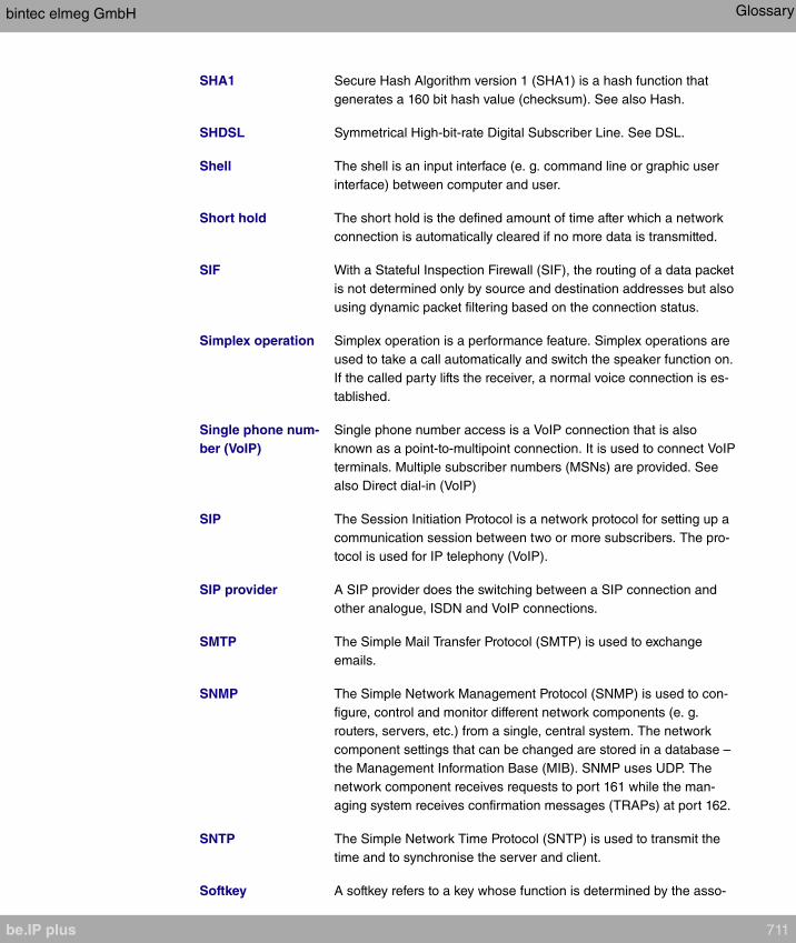
SHA1 Secure Hash Algorithm version 1 (SHA1) is a hash function that
generates a 160 bit hash value (checksum). See also Hash.
SHDSL Symmetrical High-bit-rate Digital Subscriber Line. See DSL.
Shell The shell is an input interface (e. g. command line or graphic user
interface) between computer and user.
Short hold The short hold is the defined amount of time after which a network
connection is automatically cleared if no more data is transmitted.
SIF With a Stateful Inspection Firewall (SIF), the routing of a data packet
is not determined only by source and destination addresses but also
using dynamic packet filtering based on the connection status.
Simplex operation Simplex operation is a performance feature. Simplex operations are
used to take a call automatically and switch the speaker function on.
If the called party lifts the receiver, a normal voice connection is es-
tablished.
Single phone num-
ber (VoIP)
Single phone number access is a VoIP connection that is also
known as a point-to-multipoint connection. It is used to connect VoIP
terminals. Multiple subscriber numbers (MSNs) are provided. See
also Direct dial-in (VoIP)
SIP The Session Initiation Protocol is a network protocol for setting up a
communication session between two or more subscribers. The pro-
tocol is used for IP telephony (VoIP).
SIP provider A SIP provider does the switching between a SIP connection and
other analogue, ISDN and VoIP connections.
SMTP The Simple Mail Transfer Protocol (SMTP) is used to exchange
emails.
SNMP The Simple Network Management Protocol (SNMP) is used to con-
figure, control and monitor different network components (e. g.
routers, servers, etc.) from a single, central system. The network
component settings that can be changed are stored in a database –
the Management Information Base (MIB). SNMP uses UDP. The
network component receives requests to port 161 while the man-
aging system receives confirmation messages (TRAPs) at port 162.
SNTP The Simple Network Time Protocol (SNTP) is used to transmit the
time and to synchronise the server and client.
Softkey A softkey refers to a key whose function is determined by the asso-
bintec elmeg GmbH Glossary
be.IP plus 711
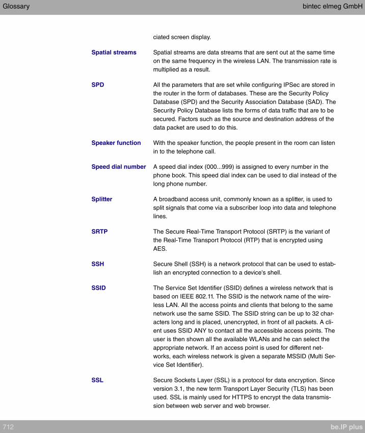
ciated screen display.
Spatial streams Spatial streams are data streams that are sent out at the same time
on the same frequency in the wireless LAN. The transmission rate is
multiplied as a result.
SPD All the parameters that are set while configuring IPSec are stored in
the router in the form of databases. These are the Security Policy
Database (SPD) and the Security Association Database (SAD). The
Security Policy Database lists the forms of data traffic that are to be
secured. Factors such as the source and destination address of the
data packet are used to do this.
Speaker function With the speaker function, the people present in the room can listen
in to the telephone call.
Speed dial number A speed dial index (000...999) is assigned to every number in the
phone book. This speed dial index can be used to dial instead of the
long phone number.
Splitter A broadband access unit, commonly known as a splitter, is used to
split signals that come via a subscriber loop into data and telephone
lines.
SRTP The Secure Real-Time Transport Protocol (SRTP) is the variant of
the Real-Time Transport Protocol (RTP) that is encrypted using
AES.
SSH Secure Shell (SSH) is a network protocol that can be used to estab-
lish an encrypted connection to a device's shell.
SSID The Service Set Identifier (SSID) defines a wireless network that is
based on IEEE 802.11. The SSID is the network name of the wire-
less LAN. All the access points and clients that belong to the same
network use the same SSID. The SSID string can be up to 32 char-
acters long and is placed, unencrypted, in front of all packets. A cli-
ent uses SSID ANY to contact all the accessible access points. The
user is then shown all the available WLANs and he can select the
appropriate network. If an access point is used for different net-
works, each wireless network is given a separate MSSID (Multi Ser-
vice Set Identifier).
SSL Secure Sockets Layer (SSL) is a protocol for data encryption. Since
version 3.1, the new term Transport Layer Security (TLS) has been
used. SSL is mainly used for HTTPS to encrypt the data transmis-
sion between web server and web browser.
Glossary bintec elmeg GmbH
712 be.IP plus

STAC STAC is used to reduce the data volume transmitted (data compres-
sion).
Static IP Address In contrast to a dynamic IP address, the static IP address is as-
signed permanently by the user. Network components such as the
web server or printer usually have static IP address, while clients
such as notebooks or workstations usually have dynamic IP ad-
dresses.
Station guarding When station guarding is enabled, acoustic call signalling is
switched off. This function is also known as Do not disturb.
STUN Server Simple Traversal of User Datagram Protocol (UDP) Through Net-
work Address Translators (NATs). A STUN server enables VoIP
devices behind an active NAT to access the network.
Sub-addressing As well as the ISDN telephone number, a sub-address can also be
sent when establishing the connection. This sub-address can trans-
mit any additional information. It can be used, e. g., to systematically
address multiple ISDN terminals that can be reached under one
telephone number, or to open particular programs on a PC.
Subnet A sub-network in an IP network is known as a subnet. A subnet is
defined like a normal network, via an IP address and (sub-)netmask
(IPv4) and prefix length (IPv6). Example: 192.168.1.250/24
(192.168.1.250/255.255.255.0, 256 possible IP addresses) is a sub-
net of 192.168.1.250/16 (192.168.1.250/255.255.0.0, 65536 pos-
sible IP addresses).
Suppress telephone
number
See Display caller number (CLIP / CLIR) and Display called party
number (COLP / COLR).
Switch A switch is a network component that connects individual network
segments to one another. On the one hand, a switch can be oper-
ated as a bridge to the data link layer in the OSI model. Unlike the
bridge, however, a switch has more than one input and output. On
the other hand, the switch can be operated as a gateway to the net-
work layer in the OSI model. The device comparable to the switch in
the physical layer is known as the hub.
Switch contact A telephone can be used to switch a device connected to the switch
contact, e. g. a door opener, on and off.
SWYX SwyxWare is a software-based communication solution for VoIP.
Syslog The syslog protocol is used to transmit status messages in an IP
bintec elmeg GmbH Glossary
be.IP plus 713
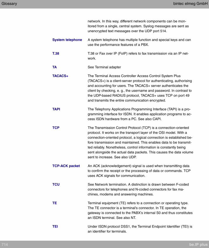
network. In this way, different network components can be mon-
itored from a single, central system. Syslog messages are sent as
unencrypted text messages over the UDP port 514.
System telephone A system telephone has multiple function and special keys and can
use the performance features of a PBX.
T.38 T.38 or Fax over IP (FoIP) refers to fax transmission via an IP net-
work.
TA See Terminal adapter
TACACS+ The Terminal Access Controller Access Control System Plus
(TACACS+) is a client-server protocol for authenticating, authorising
and accounting for users. The TACACS+ server authenticates the
client by checking, e. g., the username and password. In contrast to
the UDP-based RADIUS protocol, TACACS+ uses TCP on port 49
and transmits the entire communication encrypted.
TAPI The Telephony Applications Programming Interface (TAPI) is a pro-
gramming interface for ISDN. It enables application programs to ac-
cess ISDN hardware from a PC. See also CAPI.
TCP The Transmission Control Protocol (TCP) is a connection-oriented
protocol. It works on the transport layer of the OSI model. With a
connection-oriented protocol, a logical connection is established be-
fore transmission and maintained. This enables data to be transmit-
ted reliably. Nonetheless, control information is constantly being
sent alongside the actual data packets. This causes the data volume
sent to increase. See also UDP.
TCP-ACK packet An ACK (acknowledgement) signal is used when transmitting data
to confirm the receipt or the processing of data or commands. TCP
uses ACK signals for communication.
TCU See Network termination. A distinction is drawn between F-coded
connectors for telephones and N-coded connectors for fax ma-
chines, modems and answering machines.
TE Terminal equipment (TE) refers to a connection or operating type.
The TE connector is a terminal's connector. In TE operation, the
gateway is connected to the PABX's internal S0 and thus constitutes
an ISDN terminal. See also NT.
TEI Under ISDN protocol DSS1, the Terminal Endpoint Identifier (TEI) is
an identifier for terminals.
Glossary bintec elmeg GmbH
714 be.IP plus

Telefax See Fax.
Telnet Telecommunication Network (Telnet) is a network protocol. It en-
ables communication with another, remote device in the network, e.
g. PCs, routers, etc.
Terminal adapter A terminal adapter (TA) can be used to connect terminals to an in-
terface on which they cannot be operated directly, e. g. analogue
terminals to an ISDN connection.
TFTP The Trivial File Transfer Protocol (TFTP) regulates the transmission
of files. Compared with FTP, there is no option to display data, issue
permissions or authenticate users.
Three-party confer-
ence
The three-party conference is a performance feature. Three sub-
scribers can speak to one another on the phone simultaneously.
Tiger 192 Tiger 192 is a hash function that generates a 192 bit hash value
(checksum). See also Hash.
Time service The Time protocol is used to synchronise the date and time. The
protocol uses port 37 via TCP and UDP.
Time slot A time slot is a period of time which is permanently assigned within
a transmission frame, and is usually equivalent to one transmission
channel.
TLS See SSL.
Tone dialling See Multifrequency code dialling method.
TOS Type of Service (TOS) is a field in the header of IP data packets. It
specifies the priority of the data packet. See also QoS.
Traceroute Traceroute is used to determine which routers will be used to route
data packets to the queried destination host.
Trigger This refers to a trigger impulse.
Triple DES See DES.
Trunk A trunk consists of bundled connections or transmission channels.
See also Bundle.
TTL The Time to live (TTL) is the configured period of validity of a data
packet. With the Internet Protocol (IP), TTL specifies how many
hops a data packet may pass. The maximum value is 255 hops. The
bintec elmeg GmbH Glossary
be.IP plus 715
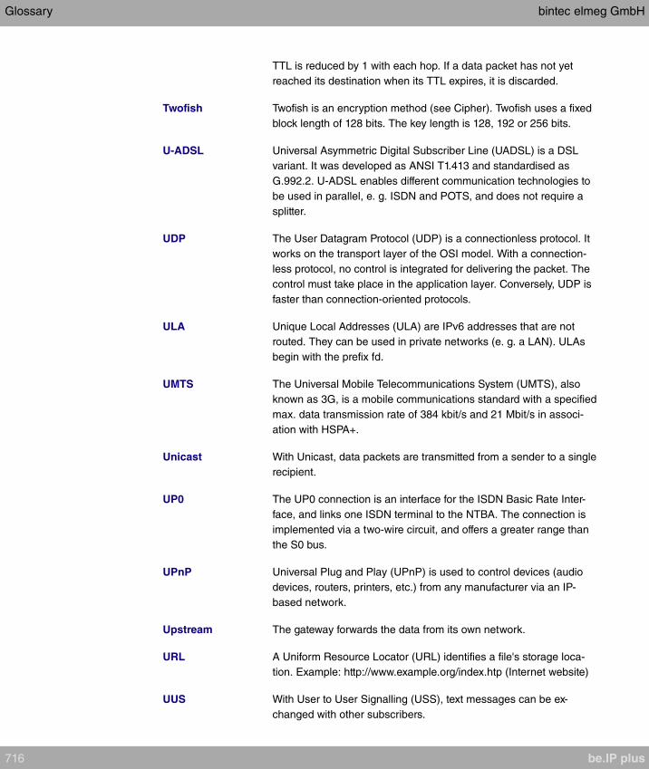
TTL is reduced by 1 with each hop. If a data packet has not yet
reached its destination when its TTL expires, it is discarded.
Twofish Twofish is an encryption method (see Cipher). Twofish uses a fixed
block length of 128 bits. The key length is 128, 192 or 256 bits.
U-ADSL Universal Asymmetric Digital Subscriber Line (UADSL) is a DSL
variant. It was developed as ANSI T1.413 and standardised as
G.992.2. U-ADSL enables different communication technologies to
be used in parallel, e. g. ISDN and POTS, and does not require a
splitter.
UDP The User Datagram Protocol (UDP) is a connectionless protocol. It
works on the transport layer of the OSI model. With a connection-
less protocol, no control is integrated for delivering the packet. The
control must take place in the application layer. Conversely, UDP is
faster than connection-oriented protocols.
ULA Unique Local Addresses (ULA) are IPv6 addresses that are not
routed. They can be used in private networks (e. g. a LAN). ULAs
begin with the prefix fd.
UMTS The Universal Mobile Telecommunications System (UMTS), also
known as 3G, is a mobile communications standard with a specified
max. data transmission rate of 384 kbit/s and 21 Mbit/s in associ-
ation with HSPA+.
Unicast With Unicast, data packets are transmitted from a sender to a single
recipient.
UP0 The UP0 connection is an interface for the ISDN Basic Rate Inter-
face, and links one ISDN terminal to the NTBA. The connection is
implemented via a two-wire circuit, and offers a greater range than
the S0 bus.
UPnP Universal Plug and Play (UPnP) is used to control devices (audio
devices, routers, printers, etc.) from any manufacturer via an IP-
based network.
Upstream The gateway forwards the data from its own network.
URL A Uniform Resource Locator (URL) identifies a file's storage loca-
tion. Example: http://www.example.org/index.htp (Internet website)
UUS With User to User Signalling (USS), text messages can be ex-
changed with other subscribers.
Glossary bintec elmeg GmbH
716 be.IP plus
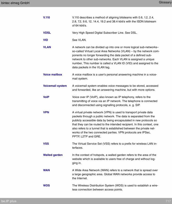
V.110 V.110 describes a method of aligning bitsteams with 0.6, 1.2, 2.4,
2.8, 7.2, 9.6, 12, 14.4, 19.2 and 38.4 kbit/s with the ISDN bitstream
of 64 kbit/s.
VDSL Very High Speed Digital Subscriber Line. See DSL.
VID See VLAN.
VLAN A network can be divided up into one or more logical sub-networks–
so-called Virtual Local Area Networks (VLAN) – by the network com-
ponents no longer forwarding the data packet of a defined sub-
network to other sub-networks. Each VLAN is assigned a unique
number, This number is called a VLAN ID (VID) and assigned to the
data packets in the VLAN tag.
Voice mailbox A voice mailbox is a user's personal answering machine in a voice-
mail system.
Voicemail system A voicemail system enables voice messages to be stored, accessed
and forwarded, like an answering machine, but with more options.
VoIP Voice over IP (VoIP), also known as IP telephony, refers to the
transmitting of voice via an IP network. The telephone is connected
and disconnected using signalling protocols, e. g. SIP.
VPN A virtual private network (VPN) is used to transport private data
packets through a public network. The data is separated from the
publicly accessible data by being encapsulated in new protocols so
that they can be routed to the intended recipient. In this context, one
also refers to a tunnel that is established between the private net-
works of the two connected parties. VPN protocols are IPSec,
PPTP, L2TP and GRE.
VSS The Virtual Service Set (VSS) refers to a prefix for wireless LAN in-
terfaces.
Walled garden In the context of hotspots, a walled garden refers to the area of the
website which is available to users free of charge and without log-
ging in.
WAN A Wide Area Network (WAN) refers to a network that is spread over
a large geographic area. Global WAN networks provide access to
the Internet.
WDS The Wireless Distribution System (WDS) is used to establish a wire-
less connection between access points.
bintec elmeg GmbH Glossary
be.IP plus 717
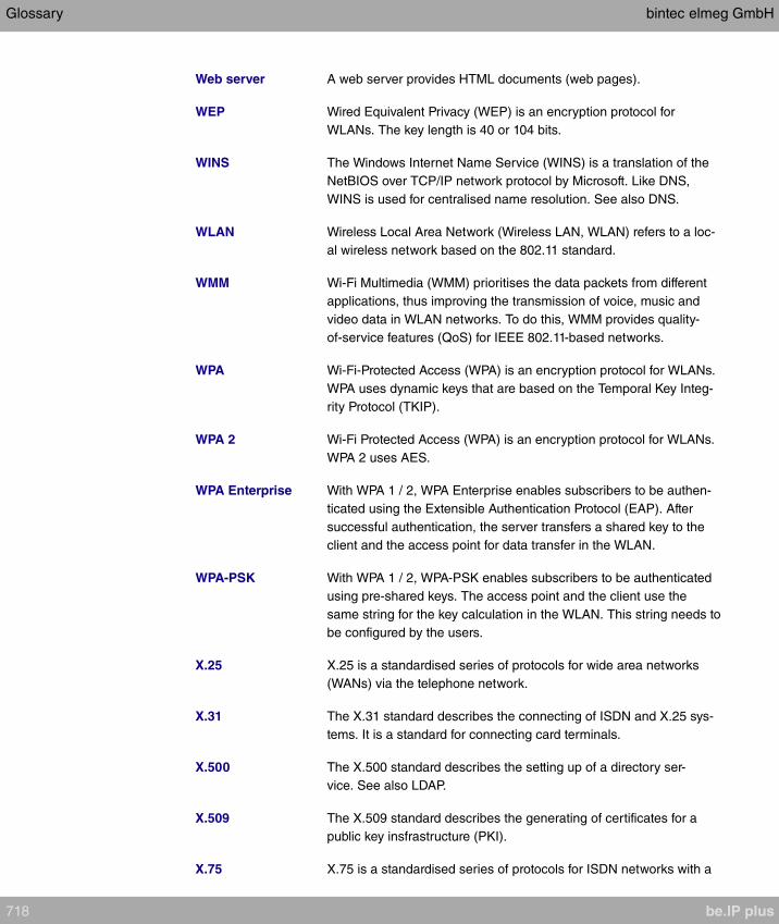
Web server A web server provides HTML documents (web pages).
WEP Wired Equivalent Privacy (WEP) is an encryption protocol for
WLANs. The key length is 40 or 104 bits.
WINS The Windows Internet Name Service (WINS) is a translation of the
NetBIOS over TCP/IP network protocol by Microsoft. Like DNS,
WINS is used for centralised name resolution. See also DNS.
WLAN Wireless Local Area Network (Wireless LAN, WLAN) refers to a loc-
al wireless network based on the 802.11 standard.
WMM Wi-Fi Multimedia (WMM) prioritises the data packets from different
applications, thus improving the transmission of voice, music and
video data in WLAN networks. To do this, WMM provides quality-
of-service features (QoS) for IEEE 802.11-based networks.
WPA Wi-Fi-Protected Access (WPA) is an encryption protocol for WLANs.
WPA uses dynamic keys that are based on the Temporal Key Integ-
rity Protocol (TKIP).
WPA 2 Wi-Fi Protected Access (WPA) is an encryption protocol for WLANs.
WPA 2 uses AES.
WPA Enterprise With WPA 1 / 2, WPA Enterprise enables subscribers to be authen-
ticated using the Extensible Authentication Protocol (EAP). After
successful authentication, the server transfers a shared key to the
client and the access point for data transfer in the WLAN.
WPA-PSK With WPA 1 / 2, WPA-PSK enables subscribers to be authenticated
using pre-shared keys. The access point and the client use the
same string for the key calculation in the WLAN. This string needs to
be configured by the users.
X.25 X.25 is a standardised series of protocols for wide area networks
(WANs) via the telephone network.
X.31 The X.31 standard describes the connecting of ISDN and X.25 sys-
tems. It is a standard for connecting card terminals.
X.500 The X.500 standard describes the setting up of a directory ser-
vice. See also LDAP.
X.509 The X.509 standard describes the generating of certificates for a
public key insfrastructure (PKI).
X.75 X.75 is a standardised series of protocols for ISDN networks with a
Glossary bintec elmeg GmbH
718 be.IP plus
transmission rate of 64 kbit/s.
XAuth XAUTH (Extended Authentication) is used to add further authentica-
tion mechanisms to IKE. After a successful phase 1 authentication,
the user can be separately identified again. The identifying is done
using the username and password, PAP, CHAP or hardware-based
systems.
Zone A zone refers to a phone number or numbers that begin with the
same sequence.
bintec elmeg GmbH Glossary
be.IP plus 719

Index
Interface 68
2,4 GHz band rate profile 351
5 GHz band rate profile 321 , 351
Accept Client FQDN 567
Accept Router Advertisement 293 ,
424 , 437
Access 568
Access Configuration 111
Access Control 319 , 350
Access Filter 409
Access Level 82
Access Type 95 , 98 , 129
Action 286 , 374 , 409 , 521 , 523 ,
576 , 606
Action to be performed 591
Active Doorcom Variant 275
Active Function 657 , 658 , 658 , 659
Active Radio Profile 337
Active Variant 269 , 278
Active Variant (Day) 141 , 160 , 167 ,
637
Additional freely accessible Domain
Names 599
Additional Info for Extern Call 147
Additional IPv4 Traffic Filter 472 , 474
Address assignment 564
Address / Prefix 527
Address / Subnet 527
Address Mode 292 , 456
Address Range 527
Address Type 527
Addresses 122
Admin Password 203 , 208
Admin Status 386
Administrative FQDNs 567
Administrative Status 468 , 541
Advertise 295
AFTR 430
Airtime fairness 307 , 340
Alarm Signalling Period 279
Alert Service 629
Alive Check 76 , 488 , 493
All Multicast Groups 418
Allow manual trunk group selection
144
Allowed Addresses 319 , 350
Allowed HotSpot Client 601
Always on 421 , 430 , 435 , 442 , 449
, 512
Announcement 253
Anrufernummer 170
Answering Machine 191 , 676
APN 556
Application 248
Assigned Users 638
Assigned Wireless Network (VSS)
337
Assignment 162 , 166 , 256 , 276
ATM Interface 455
ATM PVC 435
ATM Service Category 459
Authentication 427 , 433 , 440 , 444 ,
451 , 514
Authentication ID 111
Authentication Method 468 , 483
Authentication Type 75
Authorization 167
Auto Attendant with DISA 254
Auto Subnet Configuration 295 , 426 ,
439
Automatic Call Pick-up 180 , 665
Automatic Call Pick-up 186 , 636 ,
637 , 671
Automatic Call Pick-up with 163 , 270
Automatic Outside Line 144
Automatic Route Selection (ARS) 147
Autonomous Flag 297
Autosave Mode 89 , 576
Bandwidth 305 , 340
Based on Ethernet Interface 291
Beacon Period 320 , 343
Bell ID 275
Bell Name 275
Beschreibung 170
Blacklist blocktime 350
Index bintec elmeg GmbH
720 be.IP plus
Block after connection failure for 427 ,
433 , 440 , 444 , 451 , 514
Block Time 488
Bridge Link Name (ID) 322
Burst size 401
Busy on busy 138 , 163 , 637
Busy starting with 164
Busy when 270
CA Certificate 85
CA Certificates 488
CA Name 576
Calendar for status "Out of Office"
282
Call Center Description 269
Call Forwarding 636 , 637
Call Forwarding extern (SIP 302) 115
Call Forwarding to External Numbers
160
Call Hold inside the PBX system 115 ,
131
Call Number 447
Call Signalisation Timer 276
Call Switching 254
Call Through 143 , 150 , 259
Call Waiting 150 , 177 , 233 , 636 ,
663
Call-prefix 245
Callback Mode 444
CAPWAP Encryption 337
Certificate is CA Certificate 84
Certificate Request Description 85 ,
576
Certificate Revocation List (CRL)
Checking 84
Channel 305 , 337
Channel Bundling 446
Channel Plan 309 , 343
Charges 636
Check PIN 284 , 678
Class ID 395 , 401
Class map 395
Client Band select 318 , 348
Client Type 458
Code 530
Code for Doorcom Call Acceptance
274
Codec Profile 177 , 196 , 207 , 211
Codec Profiles 115 , 121
Codec Proposal Sequence 125
Command Mode 576
Command Type 576
Common Name 87
Compare Condition 570
Compare Value 570
Config Mode 470
Configuration contains certificates/keys
576
Congestion Avoidance (RED) 403
Connected clients 354
Connection Idle Timeout 421 , 430 ,
435 , 442 , 449 , 512
Connection State 391 , 406 , 603
Connection Type 442 , 512
Connections Nr. 196
Consider 382
Consider public holidays 249
Continuity Check (CC) End-to-End
463
Continuity Check (CC) Segment 463
Control Mode 398 , 465
Conversation Display 180 , 665
COS Filter (802.1p/Layer 2) 391 , 406
, 603
Count 576
Country 87
Create Default Route 298
Create NAT Policy 423 , 431 , 436 ,
443 , 450 , 513
CSV File Format 576
Current Class of Service 636
Custom 87
Custom DHCP Options 557
Cyclic Background Scanning 340
D Channel Mode 481
Data Packets Sequence Numbers
511
Date (DD - MM) 251
Deactivate number suppression 115
bintec elmeg GmbH Index
be.IP plus 721
Default Ethernet for PPPoE Interfaces
456
Default Idle Timeout 601
Default Route 430
Default Route 423 , 431 , 436 , 443 ,
450 , 470 , 513
Default Signalling during Calls 180 ,
665
Default User Password 75
Delete SIP bindings after Restart 115
Description 79 , 84 , 91 , 95 , 111 ,
122 , 125 , 129 , 134 , 137 , 144 ,
159 , 174 , 191 , 193 , 205 , 208 ,
231 , 232 , 236 , 239 , 242 , 243 ,
245 , 245 , 248 , 251 , 251 , 255 ,
257 , 259 , 269 , 275 , 278 , 337 ,
339 , 363 , 366 , 373 , 386 , 391 ,
395 , 401 , 406 , 409 , 421 , 430 ,
430 , 435 , 442 , 449 , 455 , 468 ,
474 , 483 , 490 , 495 , 509 , 512 ,
526 , 527 , 527 , 529 , 530 , 532 ,
541 , 554 , 558 , 570 , 576 , 603 ,
606 , 653 , 660 , 676
Destination 521 , 523
Destination immediately 657
Destination Port/Range 374 , 386 ,
391 , 406 , 603
Destination Address / Length 366
Destination Interface 544
Destination Interface 366 , 418
Destination IP Address/Netmask 362
, 374 , 386 , 474
Destination IP Address 570 , 576 ,
594
Destination IPv4 Address/Netmask
391 , 406 , 603
Destination IPv6 Address/Length 391
, 406 , 603
Destination on Busy 657
Destination on no Reply 657
Destination Port 363 , 474
Destination Port Range 530
Device 337
Devices per ticket 601
DH Group 483
DHCP Broadcast Flag 298
DHCP Client 293
DHCP Client 424 , 437
DHCP Hostname 298 , 456
DHCP MAC Address 298 , 456
DHCP Mode 299
DHCP Options 554
DHCP Server 293 , 331
Dial Control 147
Dial End Monitoring Time 115
Dialling Authorization 144
Direct Call 636
Direct Call Number 239
Direction 395
Directory Softkey 180 , 665
Display Language 177 , 203
Displayed Description 140 , 141 , 196
, 207
Displayed Name 133
Distribution Policy 382 , 383
Distribution Mode 382
Distribution Ratio 383
DNS domains search list 565
DNS Hostname 543
DNS Negotiation 427 , 433 , 440 ,
448 , 451 , 515
DNS Propagation 299
DNS Server 453 , 497 , 553 , 565
Do not Disturb 233 , 636 , 659
Do not Disturb (DND) 177 , 663
Domain 544
Domain / Realm 111
Domain at the HotSpot Server 599
Doorcom Access 156
Downstream Bandwidth Limitation
122
Dropping Algorithm 403
DSCP / TOS Value 363
DSCP Settings for rtp Traffic 124
DSCP/Traffic Class Filter (Layer 3)
391 , 406 , 603
DTIM Period 320 , 343
DTMF 125
Index bintec elmeg GmbH
722 be.IP plus
DUID 567
Dynamic blacklisting 350
E-mail 87
E-Mail Notification 282 , 679
E-mail Address 137
E-Mail Address (from User Settings)
282
E-Mail forwarding behavior 679
EAP Preauthentification 316 , 346
Early media support 115
Emergency Phone 177
Enable update 548
Enabled number 242
Encapsulation 455
Encrypt configuration 576
Encryption 444 , 514
Encryption Method 398
End-to-End Pending Requests 462
End-to-End Send Interval 462
Entries 447
Entry active 75
Event 629
Event List 570 , 576
Event List Condition 576
Event Type 570
External Assignment 162 , 276
External Number 658
External Connection Timer 279
External Filename 89 , 90
External Number 158 , 269
Facility 626
Failed attempts per Time 350
File Encoding 89 , 90
File Name 576
File Name in Flash 576
Filter 395
First External Number 280
Flash Time for DTMF Dialling 234
Force certificate to be trusted 84
Forward 544
Forward to 544
Fragmentation Threshold 309 , 343
From Domain 115
From Interface 370
Frozen Parameters 388
Function Button Status 570
Further Rerouting 164 , 270 , 637
FXS Ringing Frequency 234
G.711 aLaw 125
G.711 uLaw 125
G.722 125
G.726 (16 kbit/s) 125
G.726 (24 kbit/s) 125
G.726 (32 kbit/s) 125
G.726 (40 kbit/s) 125
G.726 Codec settings 125
G.729 125
Gateway 554
Gateway Address 366
Gateway IP Address 362
General Prefix 295 , 426 , 439
General Prefix active 370
Generate international phone number
115
Generate national subscriber number
115
Generate Private Key 85
Generation Mode 296 , 427 , 440
Global CLIP no Screening Number
112 , 130
Grace time 321 , 352
Group Description 75 , 382 , 383
Group ID 591
Headset Support 177 , 663
Hello Intervall 511
High Priority Class 395
Home Number 137
Host 544
Host Name 548
IGMP Proxy 416
IGMP Snooping 320 , 345
IGMP State Limit 415
Immediately 164
In the Office 285
Incoming Phone Number 481
Index Variables 570 , 576
Info Message (UUS1) 279
Inhibited number 242
bintec elmeg GmbH Index
be.IP plus 723
Interface 65 , 66 , 174 , 231 , 232 ,
274 , 278 , 360 , 373 , 383 , 398 ,
411 , 415 , 465 , 541 , 548 , 554 ,
564 , 576 , 593 , 599 , 608
Interface Action 593
Interface Mode 291 , 541
Interface Status 570
Interface Traffic Condition 570
Interfaces 122 , 395
Internal Assignment 136 , 162 , 276 ,
280
Internal MSN 200
Internal Number 140 , 141 , 158 , 159
, 167 , 186 , 196 , 200 , 207 , 233 ,
240 , 269 , 272 , 274 , 278 , 282
Internal Number and Rerouting Settings
167
Internal Numbers 139 , 175 , 209 ,
231 , 236
Internet Key Exchange 468
Interval 570 , 576 , 591 , 594
Intra-cell Repeating 315 , 345
IP Version of the tunneled Networks
468
IP Address 456 , 458 , 558 , 626 , 634
IP Address Assignment 470
IP Address / Netmask 292
IP Address Mode 423 , 431 , 436 ,
443 , 450 , 513
IP Address Range 331 , 453 , 497 ,
553
IP Address/Netmask 331
IP Assignment Pool 443 , 470
IP Assignment Pool (IPCP) 513
IP Compression 493
IP Pool Name 453 , 497 , 553 , 554
IP Version 529
IP Version 541
IP/MAC Binding 193 , 205
IPv4 527
IPv4 Address 543
IPv4 Back Route Verify 477
IPv4 Proxy ARP 477
IPv6 293 , 424 , 437 , 527
IPv6 Address 543
IPv6 Addresses 293
IPv6 Interface 430
IPv6 Mode 293 , 424 , 437
ISDN Synchronisation 96
Key 183 , 191 , 197 , 203 , 668 , 676
Key Extension Module 176
Key name 186 , 191 , 200 , 203 , 671
, 675
Key Size 576
Key Type 183 , 186 , 191 , 197 , 200 ,
203 , 668 , 671 , 675
Label Description 183 , 197 , 668
Language for login window 599
Last Device Configuration 191 , 676
Last Member Query Interval 415
Layer 4 Protocol 363
LCP Alive Check 427 , 433 , 440 ,
451 , 514
LDAP URL Path 91
Lease Time 554
Level 626
Level No. 79
Licence Key 60
Licence Serial Number 60
Lifetime 483 , 490
Link Prefix 295 , 426 , 439
Local Certificate 483
Local Certificate Description 89 , 90 ,
576
Local File Name 576
Local Hostname 509
Local ID 468
Local ID Type 468 , 483
Local ID Value 483
Local IP Address 362 , 423 , 431 ,
436 , 443 , 450 , 470 , 511 , 513
Local IPv6 Network 472
Local PPTP IP Address 433
Local WLAN SSID 576
Locality 87
Location 115 , 174 , 193 , 205 , 208 ,
337
Login Frameset 601
Index bintec elmeg GmbH
724 be.IP plus

Long Retry Limit 343
Loopback End-to-End 462
Loopback Segment 462
MAC Address 193 , 205 , 291 , 456 ,
558
Mail Exchanger (MX) 550
Matching String 629
Max Recording Time 282
Max waiting time in the queue 252
Max. number of clients - hard limit
318 , 348
Max. number of clients - soft limit 318
, 348
Max. Period Active Scan 311
Max. Period Passive Scan 311
Max. queue size 403
Max. Scan Duration 311
Max. Transmission Rate 343
Maximum Burst Size (MBS) 459
Maximum Downstream Bandwidth
122
Maximum Number of Dialup Retries
427 , 433 , 440 , 444 , 451
Maximum Response Time 415
Maximum Retries 511
Maximum Time between Retries 511
Maximum Upload Speed 398 , 401 ,
465
Maximum Upstream Bandwidth 122
Members 526 , 527 , 532
Menus 80
Message Compression 629
Message Timeout 629
Metric 362 , 366 , 470
MIB Variables 576
MIB/SNMP Variable to add/edit 576
Min. Period Active Scan 311
Min. Period Passive Scan 311
Min. queue size 403
Minimum Time between Retries 511
MobIKE 477
Mobile Number 137 , 207
Mode 85 , 363 , 415 , 447 , 481 , 483
, 495
Mode for status "In the Office" 284 ,
678
Mode for status "Out of Office" 284 ,
678
Module 191 , 203 , 676
Module 1: Software Version 192 , 676
Module 1: Type / Serial Number 192 ,
676
Monitored Interface 570
Monitored Subsystems 629
Monitored Variable 570
Monitored Certificate 570
Monitored Interface 593
Monitored IP Address 591
MTU 429
Multicast Group Address 418
Multiple SIP Connections
(Sub-Exchange) 211
Music on Hold 156
Mute after hands-free Calling 180 ,
665
Name 95 , 137 , 337 , 370 , 495 , 564
, 636 , 637
NAT method 373
NAT Traversal 488
Net Direct (Keypad) 156
Netmask 456 , 458
Network Name (SSID) 315 , 345
New Destination IP Address/Netmask
377
New Destination Port 377
New Source IP Address/Netmask 377
New Source Port 377
Night 138
No Hold and Retrieve 195 , 207 , 211
Number 186 , 200 , 636 , 637 , 658 ,
671 , 671
Number of allowed simultaneous Calls
115
Number of Admitted Connections 475
Number of Boss Phone 186 , 671
Number of Messages 629
Number of playbacks 254 , 279
Number of repeats 279
bintec elmeg GmbH Index
be.IP plus 725
Number of Secretary Phone 186 , 671
Number of Spatial Streams 305 , 340
Number of Used Ports 447
Numbers 166 , 271
OAM Flow Level 461
On Busy 164
On Link Flag 297
Operation Band 305 , 339
Operation Mode 305 , 337 , 339
Optional 138
Organization 87
Organizational Unit 87
Original Destination Port/Range 374
Original Destination IP Address/Net-
mask 374
Original Source Port/Range 374
Original Source IP Address/Netmask
374
OSPF Mode 448 , 515
Out of Office 285
Outbound Interface 401
Outgoing Signalisation 112 , 130 ,
140
Outgoing Phone Number 481
Overbooking allowed 401
Overwrite similar certificate 576
P-P Additional MSN 133
P-P Base Number 133
P-P DDI Exception 133
Parallel Ringing 158 , 636
Parent Location 122
Password 82 , 85 , 89 , 90 , 111 , 142
, 421 , 430 , 435 , 442 , 449 , 495 ,
509 , 512 , 548 , 568 , 576 , 606
Password for IP Phone Registration
142
Password for protected Certificate
576
PBX coupling 115
Peak Cell Rate (PCR) 459
Peer Address 468
Peer ID 468
Permanent Layer 2 Activation 96
Permit Call Forwarding 160
Personal Access 142
Phase-1 Profile 475
Phase-2 Profile 475
Phone 191 , 203 , 676
Phone Number 259 , 653
Phone Type 174 , 191 , 193 , 205 ,
676
Pick-Up Code 200
Pick-up Group 150
PIN 556
PIN (6 Digit Numeric) 167
PIN for Phone Access 142
Policy 76
Pool Usage 554
Pop-Up window for status indication
601
Port 129 , 551
Port Number 209
Port STUN server 114
Ports 129
Post Login URL 599
PPPoE Ethernet Interface 421
PPPoE Interfaces for Multilink 421
PPPoE Mode 421
PPTP Address Mode 433
PPTP Ethernet Interface 430
Preferred Lifetime 297
Preshared Key 316 , 322 , 346 , 468
Primary DNS Server DNS-Server
(IPv4/IPv6) 544
Primary IPv4 DNS Server 541
Primary IPv6 DNS Server 541
Prioritisation Algorithm 398
Prioritize TCP ACK Packets 427 , 433
, 440 , 451 , 458 , 514
Priority 75 , 401 , 541
Priority Number 242
Priority Queueing 401
Propagate PMTU 493
Proposals 483 , 490
Protocol 374 , 386 , 391 , 406 , 474 ,
530 , 551 , 576 , 603 , 626
Protocol Header Size below Layer 3
398
Index bintec elmeg GmbH
726 be.IP plus

Provider 455 , 548
Provider Name 551
Provider Status 111
Provider without Registration 115
Provisioning Server 557
Proxy 114
Proxy ARP 298
Proxy ARP Mode 448 , 515
Proxy Interface 416
Proxy Port 114
Public Interface 477
Public Interface Mode 477
Public Source IPv4 Address 477
Public Source IPv6 Address 477
Query Interval 415
Queues/Policies 398
RA Encrypt Certificate 85
RA Sign Certificate 85
RADIUS Dialout 76
RADIUS Secret 75
Radius Server 346
RADIUS Server Group ID 495
Real Time Jitter Control 398
Reboot after execution 576
Reboot device after 576
Receive Announcement Calls 156 ,
636 , 665
Receive Intercom Calls 636
Receive MWI Information 156
Receive System Intercom Call 156 ,
665
Receiving UUS 180 , 665
Recipient 629
Registrar 113
Registrar Port 113
Registration Timer 114
Relay Contact 279
Relay Contact(s) Access 156
Release Date and Time 191 , 676
Remaining Validity 570
Remote File Name 576
Remote Hostname 509
Remote IP Address 510
Remote IPv6 Network 472
Remote PPTP IP Address 433
Remote User (for Dialin only) 442
Repeat after 279
Reporting Method 411
Rerouting Application 141 , 167
Rerouting Function 270
Rerouting on no response 164 , 270 ,
637
Rerouting to Number 169
Response 543
Retries 76
Roaming Profile 311
Robustness 415
Role 322 , 495
Room Monitoring 636
Route 245
Route Active 366
Route and Charge Assignment 162
Route Class 360
Route Entries 423 , 431 , 436 , 443 ,
450 , 470 , 513
Route Selector 384
Route Type 360 , 366
Router Preference 299
Router Lifetime 299
Routing Mode 245
Routing Stage 1 246
Routing Stage 2 246
RSSI threshold 321 , 352
RTS Threshold 309 , 343
RTT Mode (Realtime Traffic Mode)
401
Rule Chain 409 , 411 , 608
Rx Shaping 320 , 351
Save call data records 156
Save configuration 80
Scan channels 311
Scan Interval 311
Scan Threshold 311
SCEP URL 85
Second External Number 280
Secondary DNS Server (IPv4/IPv6)
544
Secondary IPv4 DNS Server 541
bintec elmeg GmbH Index
be.IP plus 727

Secondary IPv6 DNS Server 541
Security Mode 316 , 346
Security Policy 292 , 293 , 423 , 424 ,
431 , 436 , 437 , 470 , 472
Segment Pending Requests 462
Segment Send Interval 462
Select file 257
Select Interface 136
Select lines 272
Select radio 576
Select vendor 556 , 557
Selected Channel 305
Selected Channels 309
Selection 529
Send WOL packet over Interface 606
Sequence of Trunk Lines in Group
134
Serial Number 174 , 191 , 676
Server 551
Server Address 576
Server IP Address 75
Server Timeout 76
Server URL 576
Service 374 , 386 , 391 , 406 , 521 ,
523 , 603
Set COS value (802.1p/Layer 2) 395
Set DSCP/Traffic Class Filter (Layer 3)
395
Set interface status 576
Set status 576
Settings 183 , 191 , 197 , 203 , 668 ,
675
Setup Mode 295 , 426 , 439
Severity 629
Short Guard Interval 309 , 343
Short Retry Limit 343
Show Connected Number (COLP)
147
Show Date and Time 234
Show incoming Name (CNIP) 234
Show incoming Number (CLIP) 234
Show incoming waiting Number (CLIP
off Hook) 234
Show new Messages (MWI) 234
Show Outgoing Number (CLIP) 147
Signal fixed out number 112 , 130
Signal remote caller number 112 ,
130
Signalling 163 , 276 , 637
Silent Deny 411
Simultaneous after time 160 , 276
Single Number (MSN) 133
SIP Client IP Address 209
SIP Client Mode 209
Size of Queue 252
SNTP Server 565
Software Version 191 , 676
Source 521 , 523
Source Address / Length 366
Source Interface 363 , 386 , 418 , 544
Source IP Address/Netmask 363 ,
374 , 386 , 474
Source IP Address 570 , 576 , 591 ,
594
Source IPv4 Address/Netmask 391 ,
406 , 603
Source IPv6 Address/Length 391 ,
406 , 603
Source Location 286
Source Location 576
Source Port 363 , 474
Source Port Range 530
Source Port/Range 374 , 386 , 391 ,
406 , 603
Special Handling Timer 386
Special Number 243
Speed Dial Number 259
SRTP 121
Standard 138
Start Mode 475
Start Time 574
State/Province 87
Static Addresses 296 , 427 , 440
Static Interface Identifier 567
Status 166 , 271 , 278 , 280 , 570 ,
636 , 660
Status LED 180 , 665
Status of Mail Box Owner 284 , 678
Index bintec elmeg GmbH
728 be.IP plus

Stop Time 574
STUN server 114
Subject 629
Subject Name 576
Subnet ID 295 , 426 , 439
Substitution of International Prefix with
"+" 115
Substitution of Incoming Number Prefix
115
Successful Trials 591
Summary 87
Sustained Cell Rate (SCR) 459
Switch call signalling 160 , 255 , 269 ,
637
Switch signalling 275 , 278
Switch signalling variants manually
150
Switch to SNMP Browser 80
Switching Points 248 , 249
System Phonebook Authorization 156
T.38 FAX support 115 , 211
Take Waiting Calls with 252
TAPI 156
Target MAC-Address 606
Target Number 253
Target Number "Immediate" 186 , 240
, 671
Target Number "On busy" 186 , 240 ,
671
Target Number "On no reply" 186 ,
240 , 671
TCP-MSS Clamping 298
Team 186 , 671
Team Speed Timer 160 , 270 , 276
Terminal 636
Terminal Endpoint Identifier (TEI) 136
Terminal Type 231 , 233
Terms &Conditions 599
Throughput 354
Throughput/client 354
Ticket Type 601
Time Condition 574
Time for Rerouting on No Reply 252
Timestamp 626
Tracking IP Address 384
Traffic Shaping 401
Traffic Direction 570
Traffic shaping 398
Transfer Mode 481
Transfer own IP address over ISDN/
GSM 481
Transfer with 253
Transferred Traffic 570
Transmit charge information 156
Transmit Charges Pulses 234
Transmit Key 316 , 346
Transmit Power 305 , 337
Transparent MAC Address 66
Transport Protocol 113 , 114 , 209
Trials 570 , 594
Trigger 593
Trigger Status 576
Trunk 133 , 166 , 169
Trunk Group Access 186
Trunk Group Access 671
Trunk Line 186 , 671
Trunk Line Selection with Line Access
Number 144
Tunnel Profile 512
Tx Shaping 320 , 351
Type 122 , 370 , 391 , 406 , 455 , 530
, 603 , 606 , 657
Type of Number 131 , 133
Type of Call Forwarding 240
Type of Messages 626
Type of Rerouting Application 255
Type of Rerouting Function 251
Type of traffic 373
U-APSD 315 , 345
UDP Destination Port 510
UDP Port 76
UDP Source Port 510
UMTS/LTE Interface 449
Unsuccessful Trials 591
Update Interval 551
Update Path 551
Upstream Bandwidth Limitation 122
Upstreaming Device with NAT 115
bintec elmeg GmbH Index
be.IP plus 729
URL 200
URL SCEP Server URL 576
Usage Area 305
Usage Type 444
Use CRL 576
Use global rerouting 150
Use PFS Group 490
Use settings from 248 , 249
Used Channel 337
Used Prefix / Length 370
Used Secondary Channel 305
User 82 , 196 , 207 , 272
User Defined Channel Plan 311 , 343
User must change password 82
User Name 111 , 142 , 421 , 430 ,
435 , 442 , 449 , 512 , 548 , 568
Users 495
Users assigned/Users logged on 637
Valid Lifetime 297
Vendor Description 556 , 557
Vendor ID 556 , 557
Vendor Mode 75
Vendor Option String 556
Vendor Specific Information (DHCP Op-
tion 43) 554
Version Check 576
Video 121
Virtual Channel Connection (VCC)
459 , 461
Virtual Channel Identifier (VCI) 455
Virtual Path Connection (VPC) 461
Virtual Path Identifier (VPI) 455
VLAN 351 , 421
VLAN ID 291 , 331 , 351 , 421
VLAN Identifier 302
VLAN Members 302
VLAN Name 302
Voice Announcement 285
Voice Mail Language 282
Volume 257
Waiting Queue 186 , 200 , 671
Wake-On-LAN Filter 606
Wake-On-LAN Rule Chain 606
Walled Garden 599
Walled Garden URL 599
Wave-File 279
Weight 401
Wildcard 550
Wildcard MAC Address 66
Wildcard Mode 66
Wireless Mode 307 , 340
WLC SSID 576
WPA Cipher 316 , 346
WPA Mode 316 , 346
WPA2 Cipher 316 , 346
Wrap-up Time 272
Wrap-up Timer 160
Write certificate in configuration 576
XAUTH Profile 475
Zones 245
Zuordnung 170
Status 621
2,4/5 GHz changeover 646
ACCESS_ACCEPT 74
ACCESS_REJECT 74
ACCESS_REQUEST 74
ACCOUNTING_START 74
ACCOUNTING_STOP 74
Action 260 , 358 , 614 , 639 , 641
Active Calls 268
Active Clients 646
Active Variant 282
Agents assigned 268
Agents in Wrap-up 268
Agents logged on 268
Alarm Input 50
Alert Service 631
Alive Check 639
Allow manual trunk group selection
661
Answer to client request 595
Answered of Calls Today 268
AP discovered 353
AP managed 353
AP offline 353
Applications 156
ARS 243
As DHCP Server 540
Index bintec elmeg GmbH
730 be.IP plus
As IPCP Server 540
Assign project codes 61
Attacked Access Point 357
Authentication for PPP Dialin 78
Authentication Method 639
Authorizations 142
Back Route Verify 369
Basic Settings 144
BOSS 614
Bridge Link Description 646 , 647
Busy on busy 660
Bytes 639
Cache Hitrate (%) 546
Cache Hits 546
Cache Size 539
Call Forwarding 656
Call Forwarding (CFNR) 57
Call from 680
Call Status 680
Call Through 652
Called Number 263 , 653
Called Number 267 , 655
Caller Number 266 , 655
CAPI Server TCP Port 569
Certificate Request 85
Charge Information (S0 / Upn Exten-
sion) 49
Charge Rate Factor 49
Check PIN 677
Class 610
Client MAC Address 645
Client Registration Timer 127
Client Subscription Timer 127
Compression 71
Configuration Interface 64
Configuration Encryption 614
Confirm Admin Password 51
Connected clients/VSS 353
Contact 44
Corrupt Frames Received 643
Costs 263 , 653
Country Profile 48
CPU usage [%] 353
CTS frames received in response to an
RTS 643
Currency 49
Current Class of Service 661
Current File Name in Flash 614
Current Local Time 54
Data Rate mbps 644 , 645
Date 263 , 263 , 266 , 267 , 638 , 653
, 654 , 655 , 655
Date/Time 680
Default Behavior 122
default MSN 97
Delete 266 , 267 , 357 , 367 , 655 ,
655
Delete call data records 265
Delete complete IPSec configuration
497
Delete Phonebook 262
Delete the complete WLAN Controller
configuration 332
Denied Clients soft/hard 646
Description 129 , 236 , 287 , 618 ,
620 , 621 , 639 , 639 , 641 , 642 ,
643 , 652 , 660
Destination File Name 614
Destination IP Address 367
Details 639
Device Info 191 , 676
DHCP Server 332
Dialling Authorization 661
Direct Call 57 , 658
DNS domains search list 565
DNS Requests 546
DNS Server 566
Do not Disturb 659
Domain Name 539
Done 358
Doorcom Signalling 50
Drop non-members 303
Drop untagged frames 303
Dropped 641 , 649
DSCP Settings for sip Traffic 127
Duplicate received MSDUs 643
Duration 263 , 263 , 653 , 654
Dynamic RADIUS Authentication 498
bintec elmeg GmbH Index
be.IP plus 731

ECDSA Key Status 70
ED25519 Key Status 70
Enable IPSec 497
Enable server 569
Enable VLAN 303
Encrypted 641
Encryption Algorithms 69
Error 358
Errors 639 , 641
Expires 610
Explicit Call Transfer 58
Export call data records 265
Extended Route 367
Extension Numbers 661
Extension Rerouting 50
External Door Connections 57
External Number 263 , 654
External Port 129
Factory Reset Firewall 526
Fallback interface to get DNS server
539
Faxheader 569
Features 148
Filename 614
Firmware Update 623
First seen 357 , 646 , 647
First Timeserver 54
Forwarded Requests 546
Frame transmissions without ACK re-
ceived 643
Function 97
Gateway 367
General 159 , 173 , 193 , 205 , 247 ,
255 , 269 , 275
Global Rerouting 49 , 50
Hashing Algorithms 69
Home Office Number 660
Host for multiple locations 602
HTTPS TCP Port 547
IGMP State Limit 417
IGMP Status 417
Ignore Certificate Request Payloads
500
IKE (Phase-1) 640
IKE (Phase-1) SAs 639
Image already exists. 358
Include certificates and keys 614
Int. No. 263 , 263 , 266 , 267 , 653 ,
654 , 655 , 655
Interconnect external calls 46
Interface 263 , 263 , 266 , 267 , 303 ,
332 , 367 , 368 , 369 , 595 , 648 ,
649 , 653 , 654 , 655 , 655
Interface Selection 609
Interface / Location 236
Interface Description 64
Interface is UPnP controlled 595
Internal Number 282 , 287 , 623 , 677
, 680
Internal Numbers 236
Internal Storage Vers. 620
Internal Time Server 54
International Prefix / Country Code 48
Invalid DNS Packets 546
IP Address 644 , 645 , 648
IP Address / Netmask 642
IP Address Range 332
IPSec (Phase-2) 640
IPSec (Phase-2) SAs 639
IPSec Debug Level 497
IPSec over TCP 498
IPSec Tunnels 640
IPv4 Firewall Status 524
IPv4 Full Filtering 524
ISDN Remote Access 623
ISDN Timeserver 54
Keys 183 , 197
Language 282 , 287
Last seen 357 , 646 , 647
Level 638
License Allocation 282
Lifetime 288
Line 268
Line Access Digit 61
Load firmware 622
Local Address 642
Local Certificate 128 , 547
Local ID 639
Index bintec elmeg GmbH
732 be.IP plus

Local IP Address 639
Local Port 639 , 642
Location 44
Log Format 628
Log on / Log off 165 , 271 , 659
Log out immediately 610
Logged Actions 524
Logging Level 71
Login Grace Time 71
Login Name 660
Logon 648
Logout Options 610
Loopback active 372
Lost Calls Today 268
MAC Address 620 , 621 , 642 , 644 ,
646 , 648
Max Call List entries for System Calls
267
Max Call List entries per User 267
Maximum Message Level of Syslog
Entries 44
Maximum E-mails per Minute 631
Maximum Groups 417
Maximum Number of Accounting Log
Entries 44
Maximum number of concurrent connec-
tions 68
Maximum Number of Syslog Entries
44
Maximum Sources 417
Maximum TTL for Negative Cache
Entries 539
Maximum TTL for Positive Cache
Entries 539
mbps 643
Memory usage [%] 353
Message 638
Messages 639
Metric 367 , 368
Mobile Number 660
Mode 369 , 417
Mode / Bridge Group 64
Mode for status "In the Office" 677
Mode for status "Out of Office" 677
MSDUs that could not be transmitted
643
MTU 639
Multicast MSDUs transmitted success-
fully 643
Multicast MSDUs received successfully
643
Multicast Routing 414
Name 97 , 261 , 660
NAT 642
NAT active 372
NAT Detection 639
National Prefix / City Code 48
Negative Cache 539
Negotiation Type 639
Netmask 367
Network Name (SSID) 357
Network Name (SSID) 646
New Calls 286 , 677
New File Name 614
No. 369 , 622 , 638 , 641
Noise dBm 644 , 645 , 646 , 647
Notification 282
Nr. 129
Number 286
Numbers 139 , 196 , 207
Old Calls 286 , 677
Optional Rerouting 141
Other Inactivity 525
Outgoing Signalisation 139
Overview 354
Packets 639
Parallel Ringing 657
Passed 641
Password 631
Password for HTML Configuration Ac-
cess 660
Password for IP Phone Registration
660
Phone Number 261 , 652
Phone Type 236 , 618 , 620 , 621 ,
622
Phone Version 620 , 621
Physical Address 648
bintec elmeg GmbH Index
be.IP plus 733
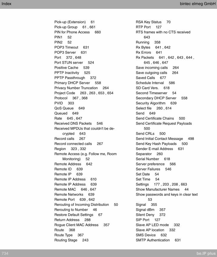
Pick-up (Extension) 61
Pick-up Group 61 , 661
PIN for Phone Access 660
PIN1 52
PIN2 52
POP3 Timeout 631
POP3 Server 631
Port 372 , 648
Port STUN server 524
Positive Cache 539
PPTP Inactivity 525
PPTP Passthrough 372
Primary DHCP Server 558
Privacy Number Truncation 264
Project Code 263 , 263 , 653 , 654
Protocol 367 , 368
PVID 303
QoS Queue 649
Queued 649
Rate 645 , 647
Received DNS Packets 546
Received MPDUs that couldn't be de-
crypted 643
Record calls 267
Record connected calls 267
Region 323 , 332
Remote Access (e.g. Follow me, Room
Monitoring) 52
Remote Address 642
Remote ID 639
Remote IP 639
Remote IP Address 610
Remote IP Address 639
Remote MAC 646 , 647
Remote Networks 639
Remote Port 639 , 642
Rerouting of Incoming Distribution 50
Rerouting to Number 46
Restore Default Settings 67
Return Address 288
Rogue Client MAC Address 357
Route 368
Route Type 367
Routing Stage 243
RSA Key Status 70
RTP Port 127
RTS frames with no CTS received
643
Running 358
Rx Bytes 641 , 642
Rx Errors 641
Rx Packets 641 , 642 , 643 , 644 ,
645 , 646 , 647
Save incoming calls 264
Save outgoing calls 264
Saved Calls 677
Schedule Interval 586
SD Card Vers. 618
Second Timeserver 54
Secondary DHCP Server 558
Security Algorithm 639
Select file 260 , 614
Send 649
Send Certificate Chains 500
Send Certificate Request Payloads
500
Send CRLs 500
Send Initial Contact Message 498
Send Key Hash Payloads 500
Sender E-mail Address 631
Separator 260
Serial Number 618
Server preference 566
Server Failures 546
Set Date 54
Set Time 54
Settings 177 , 203 , 208 , 663
Show Manufacturer Names 44
Show passwords and keys in clear text
53
Signal 355
Signal dBm 357
Silent Deny 372
SIP Port 127
Slave AP LED mode 332
Slave AP location 332
SMS Device 632
SMTP Authentication 631
Index bintec elmeg GmbH
734 be.IP plus
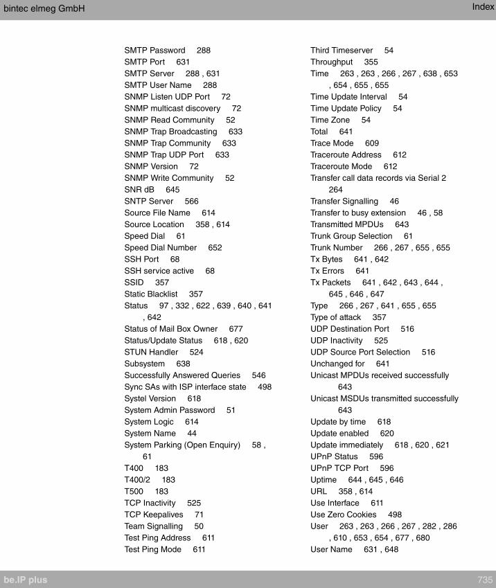
SMTP Password 288
SMTP Port 631
SMTP Server 288 , 631
SMTP User Name 288
SNMP Listen UDP Port 72
SNMP multicast discovery 72
SNMP Read Community 52
SNMP Trap Broadcasting 633
SNMP Trap Community 633
SNMP Trap UDP Port 633
SNMP Version 72
SNMP Write Community 52
SNR dB 645
SNTP Server 566
Source File Name 614
Source Location 358 , 614
Speed Dial 61
Speed Dial Number 652
SSH Port 68
SSH service active 68
SSID 357
Static Blacklist 357
Status 97 , 332 , 622 , 639 , 640 , 641
, 642
Status of Mail Box Owner 677
Status/Update Status 618 , 620
STUN Handler 524
Subsystem 638
Successfully Answered Queries 546
Sync SAs with ISP interface state 498
Systel Version 618
System Admin Password 51
System Logic 614
System Name 44
System Parking (Open Enquiry) 58 ,
61
T400 183
T400/2 183
T500 183
TCP Inactivity 525
TCP Keepalives 71
Team Signalling 50
Test Ping Address 611
Test Ping Mode 611
Third Timeserver 54
Throughput 355
Time 263 , 263 , 266 , 267 , 638 , 653
, 654 , 655 , 655
Time Update Interval 54
Time Update Policy 54
Time Zone 54
Total 641
Trace Mode 609
Traceroute Address 612
Traceroute Mode 612
Transfer call data records via Serial 2
264
Transfer Signalling 46
Transfer to busy extension 46 , 58
Transmitted MPDUs 643
Trunk Group Selection 61
Trunk Number 266 , 267 , 655 , 655
Tx Bytes 641 , 642
Tx Errors 641
Tx Packets 641 , 642 , 643 , 644 ,
645 , 646 , 647
Type 266 , 267 , 641 , 655 , 655
Type of attack 357
UDP Destination Port 516
UDP Inactivity 525
UDP Source Port Selection 516
Unchanged for 641
Unicast MPDUs received successfully
643
Unicast MSDUs transmitted successfully
643
Update by time 618
Update enabled 620
Update immediately 618 , 620 , 621
UPnP Status 596
UPnP TCP Port 596
Uptime 644 , 645 , 646
URL 358 , 614
Use Interface 611
Use Zero Cookies 498
User 263 , 263 , 266 , 267 , 282 , 286
, 610 , 653 , 654 , 677 , 680
User Name 631 , 648
bintec elmeg GmbH Index
be.IP plus 735
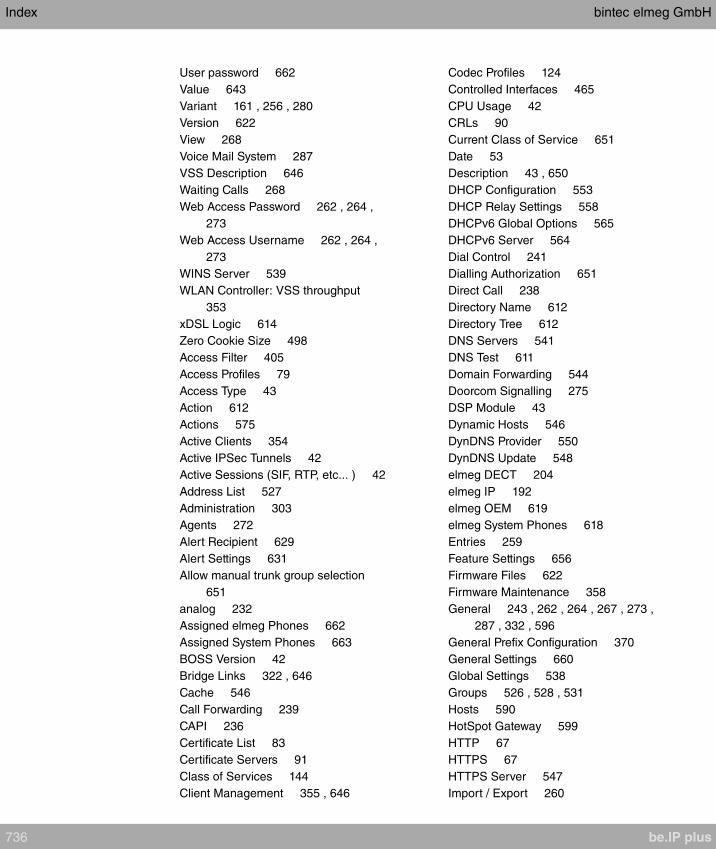
User password 662
Value 643
Variant 161 , 256 , 280
Version 622
View 268
Voice Mail System 287
VSS Description 646
Waiting Calls 268
Web Access Password 262 , 264 ,
273
Web Access Username 262 , 264 ,
273
WINS Server 539
WLAN Controller: VSS throughput
353
xDSL Logic 614
Zero Cookie Size 498
Access Filter 405
Access Profiles 79
Access Type 43
Action 612
Actions 575
Active Clients 354
Active IPSec Tunnels 42
Active Sessions (SIF, RTP, etc... ) 42
Address List 527
Administration 303
Agents 272
Alert Recipient 629
Alert Settings 631
Allow manual trunk group selection
651
analog 232
Assigned elmeg Phones 662
Assigned System Phones 663
BOSS Version 42
Bridge Links 322 , 646
Cache 546
Call Forwarding 239
CAPI 236
Certificate List 83
Certificate Servers 91
Class of Services 144
Client Management 355 , 646
Codec Profiles 124
Controlled Interfaces 465
CPU Usage 42
CRLs 90
Current Class of Service 651
Date 53
Description 43 , 650
DHCP Configuration 553
DHCP Relay Settings 558
DHCPv6 Global Options 565
DHCPv6 Server 564
Dial Control 241
Dialling Authorization 651
Direct Call 238
Directory Name 612
Directory Tree 612
DNS Servers 541
DNS Test 611
Domain Forwarding 544
Doorcom Signalling 275
DSP Module 43
Dynamic Hosts 546
DynDNS Provider 550
DynDNS Update 548
elmeg DECT 204
elmeg IP 192
elmeg OEM 619
elmeg System Phones 618
Entries 259
Feature Settings 656
Firmware Files 622
Firmware Maintenance 358
General 243 , 262 , 264 , 267 , 273 ,
287 , 332 , 596
General Prefix Configuration 370
General Settings 660
Global Settings 538
Groups 526 , 528 , 531
Hosts 590
HotSpot Gateway 599
HTTP 67
HTTPS 67
HTTPS Server 547
Import / Export 260
Index bintec elmeg GmbH
736 be.IP plus

Incoming 263 , 266 , 654 , 655
Incoming Distribution 166
Interface Assignment 410 , 608
Interfaces 64 , 289 , 593 , 595 , 627
Interfaces / Provider 244
IP Pool Configuration 552
IP Pools 452 , 497
IP/MAC Binding 557
IPSec Peers 467
IPSec Statistics 640
IPSec Tunnels 639
IPv4 Filter Rules 520
IPv4 Route Configuration 360
IPv4 Routing Table 367
IPv4/IPv6 Filter 391
IPv6 Route Configuration 365
IPv6 Routing Table 368
ISDN 231 , 442
ISDN External 95
ISDN Internal 97
ISDN Login 67
Last configuration stored 42
Lines 269
Load Balancing Groups 382
Log out Users 610
Memory Card 42
Memory Usage 42
Misdial Routing 169
Name, First Name 650
NAT Configuration 373
NAT Interfaces 372
Neighbor APs 356
Network Status 643
Night Mode Status 42
No. 43
OAM Controlling 461
Options 78 , 369 , 417 , 497 , 516 ,
524 , 569 , 586 , 602 , 613 , 628
Outgoing 263 , 266 , 653 , 655
Overview 236
Parallel Ringing 158
Passwords 50
Phase-1 Profiles 483
Phase-2 Profiles 490
Pick-up Group 651
Ping 67
Ping Generator 594
Ping Test 611
Port Configuration 302
PPPoA 434
PPPoE 421
PPTP 430
Priority Numbers 242
Profiles 454
QoS Classification 395
QoS Interfaces/Policies 397
Radio Profiles 339
Radio Settings 304
RADIUS 73
Registrar 43
Rerouting Applications 255
Rerouting Functions 251
Rogue APs 356
Rogue Clients 357
Routing 245
Rule Chains 409
Serial Number 42
Service Categories 458
Service List 529
Settings 623 , 677
SIP Provider 111
Slave Access Points 336 , 354
SNMP 67 , 72
SNMP Trap Hosts 634
SNMP Trap Options 633
Special Session Handling 385
SSH 67 , 68
Stateful Clients 567
Static Hosts 543
Statistics 546 , 641
Status 43 , 268 , 286
Syslog Servers 625
System 44
System Date 42
System Licences 59
System Messages 638
System Phone 172
System Phonebook 652
bintec elmeg GmbH Index
be.IP plus 737

System Reboot 624
Teams 637
Telnet 67
Time 53
Timer 57
Traceroute Test 612
Trigger 570
Trunk Groups 134
Trunk Numbers 132
Trunks 129
Tunnel Profiles 509
UMTS/LTE 449
Uptime 42
User 568
User Phonebook 653
Users 81 , 136 , 512 , 636
VLANs 302
Voice Mail Boxes 281
VoIP 208
VSS 644
Wake-On-LAN Filter 602
Wave Files 257
Wireless Networks (VSS) 313 , 345 ,
355
WLAN Controller 353
WOL Rules 606
X.31 135
XAUTH Profiles 495
Zones 245
Access Codes 61
Access Rules 404
Additional IPv4 Traffic Filter 466
Addresses 527
Administration 323
Administrative Access 67
Alarm Calls 277
Alert Service 629
Assigned elmeg Phones 661
ATM 453
Automatic Route Selection 243
Bridges 648
Calendar 247
Call Data Records 262 , 653
Call Distribution 166
Call List 266 , 654
CAPI Server 568
Certificates 83
Controller Configuration 332
DHCP Server 552
DHCPv6 Server 562
Diagnostics 611
DNS 537
Doorcom Units 273
DynDNS Client 548
elmeg System Phones 172 , 662
Factory Reset 624
Forwarding 418
General 413
Global Settings 44
Groups 159
HotSpot Gateway 597 , 648
HTTPS 547
IGMP 414
Interface Mode / Bridge Groups 62
Interfaces 526 , 641
Internal Log 638
Internet + Dialup 420
IP Accounting 627
IP Configuration 289
IPSec 466 , 638
IPv6 General Prefixes 370
ISDN Ports 94
L2TP 508
Load Balancing 381
Log out Users 610
Maintenance 358
Mini Call Center 268
Monitoring 353
NAT 371
Neighbor Monitoring 355
Other phones 208
Outgoing Services 238
Phonebook 652
Policies 519
QoS 391 , 649
Real Time Jitter Control 464
Reboot 624
Remote Authentication 73
Index bintec elmeg GmbH
738 be.IP plus
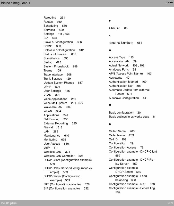
Rerouting 251
Routes 360
Scheduling 569
Services 529
Settings 111 , 656
SIA 634
Slave AP configuration 336
SNMP 633
Software &Configuration 612
Status Information 636
Surveillance 590
Syslog 625
System Phonebook 258
Teams 159
Trace Interface 608
Trunk Settings 129
Update System Phones 617
UPnP 594
User Settings 136
VLAN 301
Voice Applications 256
Voice Mail System 281 , 677
Wake-On-LAN 602
WLAN 304
Applications 247
Call Routing 238
External Reporting 625
Firewall 518
LAN 289
Maintenance 610
Monitoring 636
User Access 650
VoIP 111
Wireless LAN 304
Wireless LAN Controller 325
DHCP-Client (Configuration example)
559
DHCP-Relay-Server (Configuration ex-
ample) 559
DHCP-Server (Configuration
example) 559
NAT (Configuration example) 378
SIF (Configuration example) 532
#
#1#2, #3 88
<
<Internal Number> 651
A
Access Type 110
Access via LAN 29
Actual Network 103 , 109
Analogue Ports 98
APN (Access Point Name) 103
Assistants 40
Authentication Method 109
Authentication key 503
Automatic Update from external
Server 621
Autosave Configuration 44
B
Basic configuration 20
Basic settings in ex works state 8
C
Called Name 263
Caller Name 263
Cell ID 109
Configuration 29
Configuration Access 79
Configuration example - DHCP-Client
559
Configuration example - DHCP-Re-
lay-Server 559
Configuration example -
DHCP-Server 559
Configuration example - Load
balancing 388
Configuration example - NAT 378
Configuration example - Scheduling
587
bintec elmeg GmbH Index
be.IP plus 739
Configuration example - SIF 532
Configuration example - Time-controlled
Tasks 587
Configuration example - VoIP 212
Configured Speed / Mode 93
Current Speed / Mode 93
D
Database Record TTL (in min.) 506
Default TTL in minutes of cached EID/
RLOC entry 507
Default Ttl Mode 507
Description 507
Description - Connection Information -
Link 44
Device 109
Doorcom Signalling Variant 1 and 2
276
Downstream 100
Drilling template 15
DSL Chipset 100
DSL Configuration 99
DSL Line Profile 102
DSL Mode 101
DSL Modem 99
E
EID prefix (IP address) / Length 505
Ethernet Ports 92
Ethernet Interface Selection 93
Exclude EID prefix from tree 506
Ext. Module No 1 - 3 195
F
Fallback Number 103
Fixed IP Address 109
Flow Control 93
Function 99
Function button 570
FXS 99
G
Gathering configuration data 21
H
HMAC truncation 504 , 504
Home PLMN 109
Homepage 551
HTTP/HTTPS 29
HTTPS/SSL 548
I
ICC ID 109
IMEI 109
Incoming Service Type 103
Instance-ID 505 , 507
Interface - Connection Information -
Link 43
Interface binding 506
Internal ISDN connection 14
IP address 21
IP Version 548
K
Key type (HMAC Algorithm) 503
Keys / T400 / T400/2 / T500 668
L
Last Command 109
Last Reply 109
LISP interface MTU 507
Load balancing (Configuration
example) 388
Local Services 537
Location Area Code 109
M
Macro Function 200
Map Resolver IP Address 504
Map Server IP Address 503
Map-Register time period (in sec.)
504 , 504
Map-Resolver IP Address 506
Index bintec elmeg GmbH
740 be.IP plus
Maximum number of cached EID/RLOC
entries per ins 507
Maximum number of RLOC addresses
per cached EID 507
Maximum Upstream Bandwidth 101
MediaSec 121
Mobile Network Provider 108
Modem Model 109
Modem Status 103
Multicast 412
Multiple SIP Connections
(Sub-Exchange) 195
N
Name 99 , 110
Netmask 21
Network Provider 103
Network Quality 103 , 109
Network setting 24
Networking 360
Non-standard SMTP Server Port 288
Numbering 129
O
Off Code 200
On Code 200
Open configuration interface 30
Oper Status 109
Operating elements 30
Operation Mode (Active) 576
Operation Mode (Inactive) 576
Operation via the telephone 28
P
Password 109
Physical Connection 100
Physical Interfaces 92
Pin Assignments 16
PLMN 110
Port Configuration 93
Preferred Network Type 103
Preparations 20
Proxy-ETR-RLOC 507
PUK 103
R
Radio1 354
Reset 7
Reset button 15
Roaming Mode 108
Route Locator (RLOC) IP address
505
Rx Data Rate mbps 646 , 647
S
Scheduling (Configuration example)
587
Select all / Deselect all 680
Selected PLMN 109
Server IPv6 551
Service Center Address 109
Setting up a PC 22
Signal dBm (RSSI1, RSSI2, RSSI3)
644 , 645 , 646 , 647
SIM Card Uses PIN 103
SIP Header Field: FROM Display 115
SIP Header Field: FROM User 115
SIP Header Field: P-Asserted 115
SIP Header Field: P-Preferred 115
Smartphone 212
SNR Margin 101
Software updates 26
SRTP 196 , 211
State 110
Status 41 , 99
Subscriber Number 109
Support 13
Supports SSL 551
Switch Port 93
System Management 41
System requirements 20
Systemsoftware 20
T
T100 197
Terminals 172
bintec elmeg GmbH Index
be.IP plus 741
Termination 14
Time-controlled Tasks (Configuration
example) 587
Transmit Shaping 101
Tx Data Rate mbps 646 , 647
U
UMTS/LTE 102
UMTS/LTE Status 103
Update by time 620
Upstream 100
User access 25
Username 109
V
Variant 1 - 4 270
Video 196 , 211
VoIP (Configuration example) 212
VPN 466
W
Wall mounting 15
Walled Network / Netmask 599
WAN 420
WEP Key 1-4 316 , 346
Wizard for network setting 24
WLAN 643
WLANx 643
Index bintec elmeg GmbH
742 be.IP plus