manual do usurio - entrapassentrapass.com/pdfs/catrax clip manual.pdf · • thoroughly read the...
TRANSCRIPT

www.TURNSTILES.us
www.TURNSTILES.us / www.entrapass.com 8641 S. Warhawk Road, Conifer, CO 80421 / 303-670-1099

TABLE OF CONTENTS
1 DIRECTIONS................................................................................................ 3
2 INTRODUCTION........................................................................................... 3
3 CATRAX CLIP CHARACTERISTICS ................................................................ 4
3.1 CATRAX Clip operation............................................................................. 5 4 CATRAX CLIP INSTALLATION AND ASSEMBLY............................................. 6
4.1 Opening the package............................................................................... 6 4.2 Drilling the floor...................................................................................... 7 4.3 Fastening the column .............................................................................. 7 4.4 Arm Assembly ........................................................................................ 8 4.5 Access to the CATRAX Clip after assembly .................................................. 9
5 INSTALLATION/ASSEMBLY OF OPTIONAL ITEMS ........................................ 9
5.1 Deposit kit with urn................................................................................. 9 5.1.1 Connecting the deposit kit to the control board ................................ 10
5.2 Pictogram kit........................................................................................ 11 5.3 Power supply........................................................................................ 11 5.4 Control board ....................................................................................... 11
5.4.1 Inputs........................................................................................ 13 5.4.2 Outputs...................................................................................... 13 5.4.3 Control board configuration – Dip Switch DS1.................................. 15 5.4.4 Examples of configurations............................................................ 16
6 MAINTENANCE .......................................................................................... 16
6.1 Preventive and corrective maintenance schedule ....................................... 16 6.2 Troubleshooting.................................................................................... 18
7 TECHNICAL CHARACTERISTICS ................................................................. 19
www.TURNSTILES.us, inc. * 8641 South Warhawk Road * Conifer, Colorado 80433 Tel: 303 670 1099 ext 11 Patrick McAllister
www.TURNSTILES.us / www.entrapass.com / 8641 S. Warhawk Road, Conifer, CO 80421 / 303-670-1099

1 DIRECTIONS
• Thoroughly read the information and instructions contained in this manual beforeusing the product. This will extend the life of the product and will enable you tofully benefit from all its features.
• This product was not designed for outdoor use in unprotected areas.
• Retain this manual for future reference.
2 INTRODUCTION
Following a new technological concept focused on sturdiness and reliability, and with innovative design elements, such as varied colors and broadly curved lines, Digicon has launched as part of the CATRAX line the Clip model, aimed at serving physically disabled persons.
CATRAX Clip meets the needs of the vast majority of access control technologies presently available, being acclaimed as the best option in the access control market.
www.TURNSTILES.us, inc. * 8641 South Warhawk Road * Conifer, Colorado 80433 Tel: 303 670 1099 ext 11 Patrick McAllister
www.TURNSTILES.us / www.entrapass.com / 8641 S. Warhawk Road, Conifer, CO 80421 / 303-670-1099

3 CATRAX CLIP CHARACTERISTICS
The CATRAX Clip is an access control miniblock model (column type) aimed at persons with physical disabilities features an arm with brushed stainless steel (AISI 304) finishing and a two-way mechanism with horizontal movement.
The column finishing may be either in brushed stainless steel (AISI 304) or 1020 carbon steel with black epoxy powder electrostatic coating. It features a reinforced structure, fully rounded corners and with no exposed screws, offering space and comfort for practically any access control solution. It also features a space for a collection safe (optional item).
In order to simplify maintenance and assembly, the CATRAX Clip column has an internal U-shaped mounting rack (drawer type) with standard drilling to mount optional electronic boards. Also, extra drilling can be done by the customer according to their needs. Access to the mounting bracket is through a key with a code, and it is removed and inserted through the front door.
The top panel comprises a plastic cover and a stainless steel plate. The cover is made in an injected plastic structure and is available in stainless steel of black (other colors available upon request). Optionally, the cover may feature a slot for reading magnetic or bar code tags/cards.
The top cover stainless steel plate allows for easy configuration and customization of the product at a low cost. The plate can also feature slots for optional items, such as pictogram, deposit urn spout, display kit, or a combination of these items. The figures below show some of these options.
Detail of top cover: flat and with spout todeposit cards.
www.TURNSTILES.us, inc. * 8641 South Warhawk Road * Conifer, Colorado 80433 Tel: 303 670 1099 ext 11 Patrick McAllister
www.TURNSTILES.us / www.entrapass.com / 8641 S. Warhawk Road, Conifer, CO 80421 / 303-670-1099

Detail of pictogram
As well as compatibility with the vast majority of available technologies, Digicon can provide the following optional items:
deposit kit with urn, pictogram kit, power SUPPLY, and control board. These items are described in greater detail in section 5 Installation/Assembly of optional ITEMS
NOTE For detailed information on the dimensions of CATRAX Clip components, see section 7 TECHNICAL CHARACTERISTICS, page 19 in this manual.
3.1 CATRAX CLIP OPERATION
The CATRAX Clip basic mechanism features a two-way turning system with horizontal movement, two 12V electromagnets to activate the locks and two optical sensors that can supply a signal to activate the electromagnets and return the passage.
In the electronic model, which features a micro processed control board (optional), a signal that enables the passage is sent through one of the inputs depending on the direction of passage. If this signal is recognized, the equipment will allow the CATRAX Clip arm to move forward. Once half the turn (45 degrees) is completed, a 400 millisecond return signal is sent informing the direction of passage.
Depending on the CATRAX Clip configuration and model, forcing the arm in the absence of an enabling signal will activate an electromagnet and block the passage. Also, the equipment may also send a signal for an audible alarm and/or activate the pictogram in red in the front panel(models with pictogram). In this case, a return signal is sent indicating that the access controller was forced and informing the direction.
www.TURNSTILES.us, inc. * 8641 South Warhawk Road * Conifer, Colorado 80433 Tel: 303 670 1099 ext 11 Patrick McAllister
www.TURNSTILES.us / www.entrapass.com / 8641 S. Warhawk Road, Conifer, CO 80421 / 303-670-1099

4 CATRAX CLIP INSTALLATION AND ASSEMBLY
4.1 OPENING THE PACKAGE
As the package may contain varied items (depending on the customer order), it is extremely important to carry out a thorough visual inspection before starting the installation and assembly process. All the Digicon packages include a checklist as a guide for the inspection.
ATTENTION To avoid losing the bolts used to assemble the CATRAX Clip, and the spanners, these are shipped taped to the cardboard. Thus, before disposing of any wrapping material (plastics and cardboard), make sure that all the items in the checklist are there.
See below the parts that may come with your CATRAX Clip:
Topcover
Latch toaccess themechanism
Front pictogram
Stainless armfastened to theturing shaft
Latch to access insidethe column (space forcollection safe andcomponent drawer)
NOTE As well as the items above, CATRAX Clip may be supplied with a poser supply kit and a control board.
www.TURNSTILES.us
www.TURNSTILES.us, inc. * 8641 South Warhawk Road * Conifer, Colorado 80433 Tel: 303 670 1099 ext 11 Patrick McAllister
www.TURNSTILES.us / www.entrapass.com / 8641 S. Warhawk Road, Conifer, CO 80421 / 303-670-1099

4.2 DRILLING THE FLOOR
Before installing the CATRAX Clip, check:
1. The site chosen to install the equipment.
2. Whether there is an power source or socket close by (installation ducts).
3. Whether the site chosen is adequate to install the access controller (closedenvironments).
4. Whether there is enough clearance (at least 5 cm) between the rear part of theCATRAX Clip column and the wall. This clearance is important to ensure access to thetop panel locks and the cable passage cover.
5. Whether there is enough room for the arms to turn once the CATRAX Clip isassembled. For further details concerning equipment dimensions, see item 7TECHNICAL CHARACTERISTICS, page 19 in this manual.
6. Whether the floor is in condition to receive anchor bolts (minimum 4 cm of FCK15MPa concrete or equivalent).
ATTENTION Since installation of the CATRAX Clip requires drilling the floor, it is extremely important that the installation site be chosen carefully.
4.3 FASTENING THE COLUMN
To fasten the column to the floor, follow the steps and figures indicated.
1. Drill the floor with a 3/8” bit (redrill with a 12 mm or 1/2” bit). Make four externalholes according to measurements indicated in the figure below.
NOTE The central slit is for the cable output , and the cables must be dimensioned according to the size of the opening.
www.TURNSTILES.us, inc. * 8641 South Warhawk Road * Conifer, Colorado 80433 Tel: 303 670 1099 ext 11 Patrick McAllister
www.TURNSTILES.us / www.entrapass.com / 8641 S. Warhawk Road, Conifer, CO 80421 / 303-670-1099

2. Clean the holes, removing drilling residues.
3. Place the outside of four anchor bolts in the holes. Leave approximately 25 mm ofthe anchor bolt protrude from the hole.
NOTE We recommend the Tecnart brand anchor bolts, model AF38110, 3/8x4”.
4. Position the column and fasten it to the floor with the four bolts that come with theanchor bolts. Use a 3/4” socket wrench or articulated ratchet spanner.
4.4 ARM ASSEMBLY
After drilling the floor and installing the column, it is possible to assemble the arm and plastic covers.
Below is a sequence of instructions and figures to help assemble the CATRAX Clip arm. TURNSTILES recommends that at least two people carry out the assembly.
1. After unpacking and installing the CATRAX Clip, place the arm close to the frontholes on the tube (central shaft). First fit the lower arm rod, then press the top rod forit to reach the respective hole.
2. Once the arm has both rods duly fitted, turn the arm to one side up toapproximately 180 degrees or until it reaches the end of its travel. You will noticethere are two holes on the back part of the tube.
www.TURNSTILES.us, inc. * 8641 South Warhawk Road * Conifer, Colorado 80433 Tel: 303 670 1099 ext 11 Patrick McAllister
www.TURNSTILES.us / www.entrapass.com / 8641 S. Warhawk Road, Conifer, CO 80421 / 303-670-1099

3. Use a # 5 Allen wrench to fasten the arms to the holes using the bolts and washersthat come with the product.
4. The following figures show the CATRAX Clip with the arm assembled and fastened(position zero and end of travel).
4.5 ACCESS TO THE CATRAX CLIP AFTER ASSEMBLY
After the CATRAX Clip has been installed and assembled, access to the inside of the equipment is possible using the key that comes with the equipment in three ways:.
- rear cover;- front cover;- column door.
5 INSTALLATION/ASSEMBLY OF OPTIONAL ITEMS
Although it is compatible with the majority of the access control technologies currently available, Digicon also offers several optional items that allow for improving and adapting the operation of the CATRAX Clip to customer needs. Below are descriptions for each one of these items.
5.1 DEPOSIT KIT WITH URN
The deposit kit with urn features a card or tag collection, retention and retrieval device. Ideally suited for places that receive eventual visitors or users. The kit has a spout, a solenoid-activated retention device and a storage urn. The following figure shows the items that come with the deposit kit and may serve as a guide for its assembly.
www.TURNSTILES.us, inc. * 8641 South Warhawk Road * Conifer, Colorado 80433 Tel: 303 670 1099 ext 11 Patrick McAllister
www.TURNSTILES.us / www.entrapass.com / 8641 S. Warhawk Road, Conifer, CO 80421 / 303-670-1099
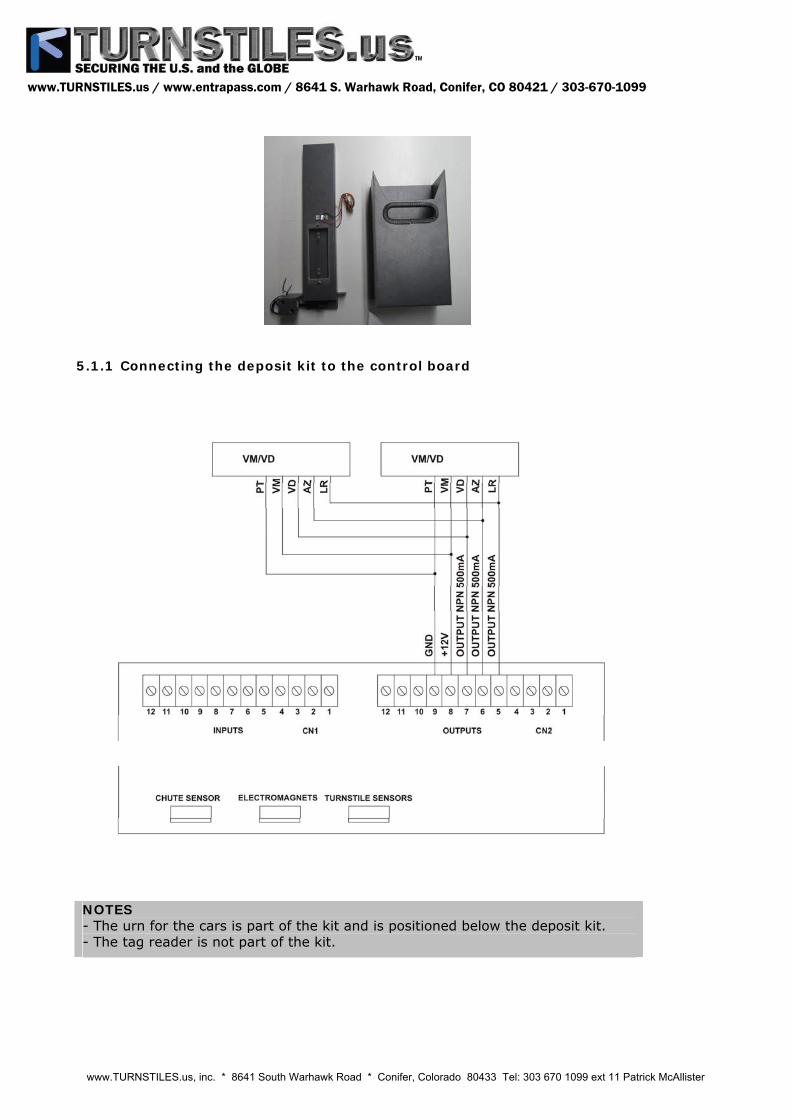
5.1.1 Connecting the deposit kit to the control board
NOTES - The urn for the cars is part of the kit and is positioned below the deposit kit.- The tag reader is not part of the kit.
www.TURNSTILES.us, inc. * 8641 South Warhawk Road * Conifer, Colorado 80433 Tel: 303 670 1099 ext 11 Patrick McAllister
www.TURNSTILES.us / www.entrapass.com / 8641 S. Warhawk Road, Conifer, CO 80421 / 303-670-1099

5.2 PICTOGRAM KIT
The pictogram kit visually signals when the passage is allowed (green color), and when it is blocked (red color). The pictogram is installed on the front part of the plastic cover.
Detail of pictogram
5.3 POWER SUPPLY
This power supply was especially designed for the CATRAX line. Among the main advantages of this optional item is its ability to adapt to voltage variations that are common in many installation sites – the input voltage may vary between 90 and 250 VAC.
The technical characteristics, protections and specific dimensions of this power supply were thoroughly tested and approved under the most adverse environmental and temperature conditions, which ensures an appropriate supply for equipment operation. On top of the input and output voltages indicated in the figure below, the power supply is also protected against short circuits and overheating.
NOTE The power supply can be fastened to the board mounting rack provided with the CATRAX Clip.
ATTENTION The supply does not have a ground cable input. Grounding is to be made directly on the ratchet casing using the board mounting rack fastening bolt.
5.4 CONTROL BOARD
The CATRAX Clip control board was designed to meet the needs of the majority of currently available access control technologies. The controller features three mechanical characteristics and layout perfectly suited to the CATRAX Clip needs, and is one of the best options for equipment operation.
www.TURNSTILES.us, inc. * 8641 South Warhawk Road * Conifer, Colorado 80433 Tel: 303 670 1099 ext 11 Patrick McAllister
www.TURNSTILES.us / www.entrapass.com / 8641 S. Warhawk Road, Conifer, CO 80421 / 303-670-1099

The table below describes the functions of the control board connectors.
Signal
Name/Description
CN1 INPUTS 1 +Vext1 (to enable passage by tension)2 HAB1 (right to left direction)3 GND4 Vext2 (to enable passage by tension)5 HAB2 (left to right direction)6 GND7 +12VDC (available for auxiliary – maximum of 500 mA)8 CLOCK1 (input for reader, left to right direction)9 DATA1 (input for reader, left to right direction)10 CLOCK2 (input for reader, right to left direction)11 DATA2 (input for reader, right to left direction)12 GND
CN2 OUTPUTS 1 NA or NF contact (HAB1 return) 2 C contact (HAB1 return) 3 NO or NC contact (HAB2 return) 4 C contact (HAB2 return) 5 Output for X indicator (NPN open collector – maximum 500 mA) – orange wire 6 Output for → arrow (NPN open collector – maximum 500 mA) – blue wire 7 Output for ← arrow (NPN open collector – maximum 500 mA) – green wire 8 +12VDC (power for indicator arrows) – red wire9 GND (power for indicator arrows) – black wire10 + tag collector urn solenoid11 - tag collector urn solenoid12 audible signal (open collector - NPN)
CN8 POWER – Power input 1 +12VDC power input2 GND power input
CN9 URN SENSOR 1 LED anode 2 Urn signal 3 GND 4 GND
CN10 ELECTROMAGNETS 1 + electromagnet 12 - electromagnet 13 + electromagnet 24 - electromagnet 2
CN11 OPTICAL SENSORS 1 Sensor signal 1 2 LED 1 anode 3 Sensor signal 2 4 GND 5 LED 2 anode
www.TURNSTILES.us, inc. * 8641 South Warhawk Road * Conifer, Colorado 80433 Tel: 303 670 1099 ext 11 Patrick McAllister
www.TURNSTILES.us / www.entrapass.com / 8641 S. Warhawk Road, Conifer, CO 80421 / 303-670-1099

NOTES - Optical sensor (CN11) and electromagnet (CN10) cables are supplied with theCATRAX Clip.- The urn sensor (CN4) cable is supplied with the deposit kit (optional).
5.4.1 Inputs
The input and passage enabling (HAB1 and HAB2) signals can originate from relay contact, pushbutton, or 5 to 24 VAC/DC or 110 to 220 VAC/DC voltages.
To enable the passage through relay contact or pushbutton, make the connection according to the figure below:
Passage enabling through voltage pulse is shown in the following figure. Follow the polarity for DC voltages and use an external resistor for high voltages (110 to 220 V).
The control board also has inputs for optical sensors (CN11) that monitor CATRAX Clip turning (no mechanical wear), and two opto-insulated inputs to release the CATRAX Clip if needed.
5.4.2 Outputs
The CATRAX Clip board features outputs for return signals, electromagnets, pictograms, deposit box, and audible alarm.
5.4.2.1 Return signals
The return signals indicate the moment and the direction of passage and are originated at a relay – normally open (NO), or normally closed (NC) contact. Connect the outputs according to the figure below.
CN2
RET1
NA
NFS2C
RL2
1
2
CN2
RET2
NA
NFS1C
RL1
3
4
www.TURNSTILES.us, inc. * 8641 South Warhawk Road * Conifer, Colorado 80433 Tel: 303 670 1099 ext 11 Patrick McAllister
www.TURNSTILES.us / www.entrapass.com / 8641 S. Warhawk Road, Conifer, CO 80421 / 303-670-1099

5.4.2.2 Electromagnets
The electromagnets are activated to block the passage. Unlike traditional solenoids, electromagnets do not cause friction between the spool and the locking device, preventing malfunction problems. Also, activation is done through a transistor, not a relay, preventing burning the electromagnets due to “contact binding” (no mechanical wear).
5.4.2.3 Audible alarm
The audible alarm output is activated by an NPN transistor (maximum 500 mA) whenever the CATRAX Clip:
- receives a release signal (two brief beeps);- has not been released and is forced for 1 second (1 second beeps);- stops in the middle of a turn for more than 2 seconds (1 second beeps).
Connect the outputs according to the figure below.
5.4.2.4 Connection schematics
www.TURNSTILES.us, inc. * 8641 South Warhawk Road * Conifer, Colorado 80433 Tel: 303 670 1099 ext 11 Patrick McAllister
www.TURNSTILES.us / www.entrapass.com / 8641 S. Warhawk Road, Conifer, CO 80421 / 303-670-1099

5.4.2.5 Pictogram
Pictogram outputs are activated by NPN transistors (maximum 500 mA). On activation, GND is sent through the corresponding output.
5.4.2.6 Pictogram connections
5.4.3 Control board configuration – Dip Switch DS1
DS1 dip switch is used to configure the following actions:
- direction of passage;- maximum passage time;- NO inputs (normally open relay or pushbutton contacts without input voltage) toenable passage in the presence of these signals, or NC inputs (normally closed relay orpushbutton contacts with input voltage) to enable passage in the absence of thesesignals;- enable an audible alarm signal if the access controller stops in mid turn for over 2seconds.
To program the DS1, place each pin in the desired position according to the table below.
01 02 03 04 05 06 07 08 Release both directions - - - OFF OFF - - -Locked left to right direction - - - ON OFF - - -Locked right to left direction - - - OFF ON - - -Locked both directions - - - ON ON - - -
www.TURNSTILES.us, inc. * 8641 South Warhawk Road * Conifer, Colorado 80433 Tel: 303 670 1099 ext 11 Patrick McAllister
www.TURNSTILES.us / www.entrapass.com / 8641 S. Warhawk Road, Conifer, CO 80421 / 303-670-1099

NO inputs - ON - - - - - - NC inputs - OFF - - - - - - Enable audible signal in mid turn - - - - - ON - - Disable audible signal in mid turn - - - - - OFF - - Wait for first turn - - - - - - ON ON Hold for 5 seconds - - - - - - OFF ON Hold for 10 seconds - - - - - - ON OFF Hold for 15 seconds - - - - - - OFF OFF Enable by edge - - OFF - - - - - Enable by level - - ON - - - - -
NOTES - The control board can be fastened to the mounting rack that comes with theCATRAX Clip.- The shaded fields indicate the default configuration of the board.
5.4.4 Examples of configurations
1 - Configuration of controller to receive on relay pulse (normally open contact), release turn the hold the passage for 10 seconds:
1 2 3 4 5 6 7 8 Configuration - ON OFF ON ON - ON OFF
2 - Configuration of controller to leave the clockwise direction always released and, upon receiving the release signal at HAB2 (counter clockwise), release passage for indeterminate time.
1 2 3 4 5 6 7 8 Configuration - ON OFF OFF ON - ON ON
3 - Configuration of the controller to release turn while the relay has a closed contact, and as soon as the relay contact opens remove the release.
1 2 3 4 5 6 7 8 Configuration - ON ON ON ON - ON ON
6 MAINTENANCE
6.1 PREVENTIVE AND CORRECTIVE MAINTENANCE SCHEDULE
Sphere base – Frequency: every 700,000 cycles
Check the sphere tracks for wear.
Corrective actions: 1. If there is excessive wear (shards, perforations, steel filings or grooves where the
sphere runs), replace the part.2. If the part does not show wear signs, clean and grease it using bearing grease.
www.TURNSTILES.us, inc. * 8641 South Warhawk Road * Conifer, Colorado 80433 Tel: 303 670 1099 ext 11 Patrick McAllister
www.TURNSTILES.us / www.entrapass.com / 8641 S. Warhawk Road, Conifer, CO 80421 / 303-670-1099

Optical sensors – Frequency: at least once a year (depending on environmental conditions)
This maintenance procedure requires the use of a multimeter. To check for the need of corrective actions, it is necessary to measure the CN11 when the controller is powered, according to the instructions below: - Set the multimeter to measure DC voltage of up to 20 V. Next, place the blackpointer on pin 4 and the red pointer on pin 1 on CN11. Voltage should be under 0.8 V(non-obstructed sensors). With the pointers in the same position, force the equipmentarm on both sides (on one side the voltage should be higher than 4.5 V).- Repeat the operation in the previous placing the black pointer on pin 4 and the redpointer on pin 3 on CN11. The results obtained should be the same as those on pins 4and 1.- Check the sensors for signs of dust.
Corrective actions: 1. If the measurements do not match the results above, replace the faulty sensor.2. Clean the sensors with a clean brush.
NOTE In excessively dusty environments, perform this maintenance procedure more frequently.
Electromagnets - Frequency: every 700,000 cycles
This maintenance procedure requires the use of a multimeter. To check for the need of corrective actions, disconnect the CN10 from the access controller board and check electromagnet resistance. The value should be between 12.5 and 13.5 ohms on pins 1, 2, 3, and 4 of the electromagnet connector. After measuring, reconnect CN10 to the board.
Corrective actions: 1. Replace the electromagnet if incorrect resistance, electromagnet in short or open
circuit is observed.2. If the electromagnet is not working, check the board and the voltage.3. If the electromagnet is moving, tighten the base bolts.
Electromagnet adjustment (if necessary): 1. Force the lock against the sprocket and the equipment arm until the lock is totally
inside the first tooth (until the arm locks).2. Next, release the fastening bolts and press the electromagnet against the lock
buffer so that all its area contacts the electromagnet.3. Retighten the bolts.
Lock assembly – Frequency: every 700,000 cycles
To check for the need of corrective actions, you should: - Check the correct lock position.- Check the lock fitting to the sprocket for wear.
Corrective actions: 1. If the lock is incorrectly positioned, check the retention ring and the spring that
tensions the assembly.2. If the lock fitting to the sprocket is incorrect, replace the lock or the sprocket.3. If there are signs of wear on the lock end, replace the lock.
www.TURNSTILES.us, inc. * 8641 South Warhawk Road * Conifer, Colorado 80433 Tel: 303 670 1099 ext 11 Patrick McAllister
www.TURNSTILES.us / www.entrapass.com / 8641 S. Warhawk Road, Conifer, CO 80421 / 303-670-1099

Sprocket assembly – Frequency: every 700,000 cycles
To check for the need of corrective actions, you should: - Check the sprocket teeth for wear.- Check the clearance between the central shaft, the sprocket and the cotter pin.
Corrective actions: 1. If you observe any signs of wear on the part teeth replace the sprocket.2. If you notice excess clearance between the sprocket and the shaft/cotter pin
assembly, replace the sprocket or the cotter pin (to change the sprocket, use apulley extractor).
6.2 TROUBLESHOOTING
Defect Likely causes Action • CATRAX Clip will not go
on• Power supply cable is not connected
properly.• Power supply fuse is burnt.
• Check the wiring and the fuse(fuse: 3 A).
• CATRAX Plus is locked • Optical sensors are obstructed ordefective.
• Carry out preventivemaintenance procedures inthe sensors or send theequipment to TechnicalAssistance.
• CATRAX Plus will notactivate electromagnet(always released)
• The cable is broken or the distancebetween the electromagnet and the lockdevice is out of adjustment.
• Adjust the electromagnet orsend the equipment toTechnical Assistance.
• Arm will not stay in thecorrect position
• The sphere base is worn, dirty, has abroken spring or lacks lubrication.
• Request replacement of thedefective part or send theequipment to TechnicalAssistance.
• CATRAX Plus will notlock on the first tooth.
• The distance between the electromagnetand the locking device is out ofadjustment.
• Adjust the electromagnet orsend the equipment toTechnical Assistance.
www.TURNSTILES.us, inc. * 8641 South Warhawk Road * Conifer, Colorado 80433 Tel: 303 670 1099 ext 11 Patrick McAllister
www.TURNSTILES.us / www.entrapass.com / 8641 S. Warhawk Road, Conifer, CO 80421 / 303-670-1099

7 TECHNICAL CHARACTERISTICS
DimensionsSide view:
Top view:
Packaging: Height: 103 cm Width: 27 cm Depth: 55 cm
Other informationGross weight: 37 kg (+ 2 kg of packaging) Electromagnet power supply: 12 V and 2 A Sensor power supply: 5 V and 0.5 A Power supply (optional) Input: 85 V to 250 VAC
Output: 12.3 V ± 5% / 2 A, and 5 V ± 5% / 1 A Dimensions: 35 x 51 x 105 mm Distance between holes: 43 x 98 mm Hole diameter: 3.5 mm
www.TURNSTILES.us, inc. * 8641 South Warhawk Road * Conifer, Colorado 80433 Tel: 303 670 1099 ext 11 Patrick McAllister
www.TURNSTILES.us / www.entrapass.com / 8641 S. Warhawk Road, Conifer, CO 80421 / 303-670-1099