manual. maximailer various options · 2018-03-22 · maximailer/automailer 4, ... c8194a slotted...
TRANSCRIPT

Page 1 of 5ISSUE 1420/102/1SEP 2004
P.F.E. INTERNATIONALTO : ALL UK ENGINEERS AND OVERSEAS AGENTS
TECHNICAL BULLETIN N0. 1420/102
Please ensure this Technical Bulletin is read by all technical staff involved in the maintenanceand repair of P.F.E machines.
This bulletin must be read by all P.F.E. engineers involved in the maintenance and service ofMaximailer/Automailer 4, and must be attached to all copies of the Maximailer/Automailer 4 ServiceManual.
MAXIMAILER VARIOUS OPTIONS
This Technical Bulletins covers a number of options available to enhance functionality for specificneeds.
1. Operator-settable separator (3 Plate Folder)2. Mods for glossy material (3 Plate Folder)3. Anti-static Brushes (3 Plate Folder Accumulator)4. Alternative feed tyres and parts (Feeder, Head & 3 Plate Folder)5. Technical Tips document
Description and fitting of these options is shown below.
1. Operator-settable separator
The standard separator on the 3 plate folder is spring-loaded and operates with a preset gap for 80gsm(20lbs bond) paper. Under certain circumstances (eg. extra thick material) it may be necessary to openthe gap, or in some cases to close it. As standard, this is an engineer operation (described in section3.3.1 in the Service Manual), but with some stationery, this may not provide a sufficiently sensitiveadjustment. The operator-settable separator allows the operator to set the gap using a knurled knobafter opening the side cover of the 3 plate folder. It can be specially useful when double feeding hasbeen a problem with the standard separator, as it allows 'fine tuning'. The retrofit includes a specialinternal (black) cover to provide access to the knurled knob.
Retrofit Kit
To obtain the retrofit kit, order part no. A3263A (3-tray machines) or A3264A (1-tray machines).This consists of the following parts.Quantities shown in brackets are for 1-tray machines
Part No. Description Qty.
B4402A SEPARATOR ADJUSTOR BRKT ASSY. 3 (1)C4405A SEPARATOR ADJUSTOR SHAFT 3 (1)E0062A STEEL BALL 4mm DIA 3 (1)E2505A SCREW M4 SOCKET SET x 6 3 (1)E2566A SCREW M5 SOCKET SET x 8 3 (1)E5073A CIRCLIP 9.5mm ‘E’ TYPE 6 (2)F4029A GEAR CLICK STOP 16T 32DP 3 (1)G1028A SPRING GRIPPER 6 (2)G1046A SPRING INDEX 3 (1)
cont.

Page 2 of 5ISSUE 1420/102/1SEP 2004
G3047A I SEPARATOR INDICATOR 3 (1)P2370E SEPARATOR ADJUSTOR WHEEL 3 (1)R2671A SEPARATOR SIDE ARM OS 3 (1)R2682F INTERNAL COVER BASE 1 (1)R2683F 3 STN INTERNAL COVER 1 (0)R2681F 1 STN INTERNAL COVER 0 (1)
Retrofit Procedure
Note: LH and RH are viewed as from behind the paper path.
1. If not already supplied as a single assembly, assemble the separator bracket assembly as shownin section 4c-40 in the Service Manual.
2. Open the side cover on the LH side of the machine and remove the side cover on the RH side.Also remove the black internal cover on the LH side. This reveals the separators, as shown inFig. 1 below. There is one separator for each tray fitted.
3. Remove and discard the spring, and also the spring on the RH side, then remove the 2 screwssecuring the pivot plate to the separator beam. Take off the plate and discard it. Remove thebracket assembly below the plate and discard it.
4. Fit the new bracket assembly using existing screws, then the new pivot plate, also using existingscrews, as shown in Fig. 2 below.
Pivot arm
Bracketassembly
Fig. 1
Spring
Fig. 2
Page 3 of 5ISSUE 1420/102/1SEP 2004
5. Fit the new spring on both LH and RH sides
6. If not already done, assemble both halves of the new black cover together using M4 x 8 caphead screws E2509A with M4 washers E4011A. Attach the cover using existing screws.
7. Set the separator gap to suit 80gsm (20lbs bond) paper, or to a different setting as required.This is most easily achieved by removing the top tray, and for 3-tray machines, the second trayalso. Lift out the infeed bridge (with cork strips) to prevent drag from the pre-feeder. Slide asheet of the stationery into the separator gap and adjust the knurled knob until a moderate dragis felt on the paper as it is withdrawn rearwards. Refit the infeed plate and trays.
8. Refit the side cover and test run the machine. Make further separator adjustments if required.
2. Mods for glossy material
If glossy material is being used, feeding may be improved by the fitting of an alternative infeed guideB0173A and a stronger platform spring G1215A on the top hopper.
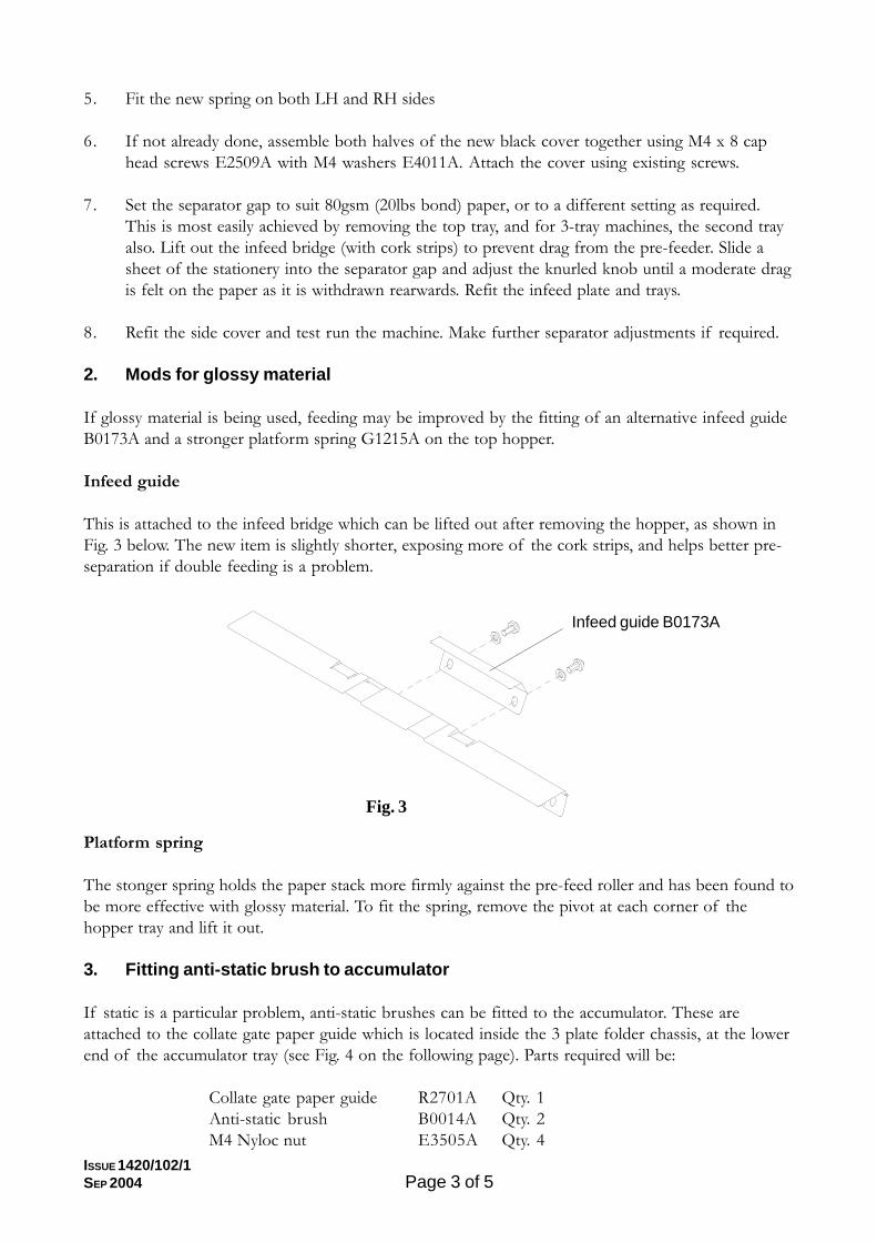
Infeed guide
This is attached to the infeed bridge which can be lifted out after removing the hopper, as shown inFig. 3 below. The new item is slightly shorter, exposing more of the cork strips, and helps better pre-separation if double feeding is a problem.
Platform spring
The stonger spring holds the paper stack more firmly against the pre-feed roller and has been found tobe more effective with glossy material. To fit the spring, remove the pivot at each corner of thehopper tray and lift it out.
3. Fitting anti-static brush to accumulator
If static is a particular problem, anti-static brushes can be fitted to the accumulator. These areattached to the collate gate paper guide which is located inside the 3 plate folder chassis, at the lowerend of the accumulator tray (see Fig. 4 on the following page). Parts required will be:
Collate gate paper guide R2701A Qty. 1Anti-static brush B0014A Qty. 2M4 Nyloc nut E3505A Qty. 4
Infeed guide B0173A
Fig. 3

Page 4 of 5ISSUE 1420/102/1SEP 2004
Collate gate paper guideR2701A
Anti-static brushB0014A
M4 Nyloc nutE3505A
Note that collate gate paper guide R2701A is fitted with M4 studs for attaching the brushes - plateswithout brushes are R2352A. To retrofit the brushes, the overguide must be removed - proceed asfollows:
1. Open the LH side cover of the 3 plate folder and remove the black inner cover. Also removethe RH side cover (section 3.1.2 in the Service Manual).
2. On the RH side, remove gears as shown in Fig. 5 below. Remove the 'E' clip and flanged bear-ing on the overguide shaft. Also remove the 'E' clip, waved washer and flanged bearing on theLH side. Lift the overguide out of the machine.
3. Remove the 2 screws each side securing the collate gate paper guide and fit the new item afterattaching the anti-static brushes.
4. Refit the overguide, gears and side covers. (Remember the drive pin for the gear on the RHside).
Fig. 4
Extrusion shown forreference only
Fig. 5
Overguide shaft -remove gear anddrive pin for accessto 'E' clip
Remove idlepost and gear
Screws for collategate paper guide

Page 5 of 5ISSUE 1420/102/1SEP 2004
4. Feed Problems
Note: This section will also be shown in the Service Manual for a more permanent record.
Below are details of non-standard tyres and parts that may help to solve some feed problems. Note thatsome separation problems with glossy or semi-glossy paper may be due to the separator tyres, pads andtransport wheels becoming coated with paper glazing agent. When this occurs the solution is to ensurefrequent cleaning of these items.
5. Technical Tips
A Technical Tips document is published periodically, and may be accessed from the PFE website atwww.pfe.co.uk. Go to Technical Information/Downloads/Maximailer. Note that this area of the websiteis password protected. If you do not know your userrname and password, contact Russell Barnes [email protected].
PartNumber
Roller/Separat-or Tyre
Appli-cation
Qty. Description
D0052A Jog TyreEnvelopeFeeder &Insert Feeder
2 off (fittedto outerwheels)
These tyres are standard on the envelope feed and areused to provide improved grip and drive.
C8194ASlottedFeed Tyre
EnvelopeFeeder &Insert Feeder
6 offThis feed wheel has advantages when feeding insertswith a powdery finish.
D0037ASiliconFeed Tyre
EnvelopeFeeder &Insert Feeder
6 off These provide added grip on certain glossy stationery.
C8193ARoller Hi -GripEPDM
EnvelopeFeeder &Insert Feeder
6 off These provide added grip on certain glossy stationery.
A7174ASpecial InsSeparatorAssembly
Insert Feeder 1 offThis version exposes more of the friction pad to theinsert pack and can help with forms that are provingdifficult to separate.
B0173AInfeedGuide
3 PlateFolder
1 off perhopper
Alternative infeed guide exposes more cork to assistpre-separation of glossy stationery.
G1215A Spring3 PlateFolder (tophopper)
1 offAlternative Platform Spring (Stronger) that improvesfeeding separation of glossy stationery.
B7803A Overguide Insert Feeder 1 off
An over-guide is available to overcome feed problemsassociated with peeling open of folded documents onpick-up. This is a guide similar to the one used to keepthe envelope flap closed on the envelope feeder.
D0058A
SiliconSlottedFeedWheel
EnvelopeFeeder &Insert Feeder
6 off These provide added grip on certain glossy stationery.
D0059A
CoatedSiliconFeedWheel
EnvelopeFeeder &Insert Feeder
6 off These provide added grip on certain glossy stationery.
A7217A(B1864S
cover)
Pre-feedAssembly
EnvelopeFeeder
1 offThis assembly can be fitted to improve the pickup ofpropeller cut envelopes.Note. B1864S cover must befitted with this assembly.