manual of energy-saving circulation pump magi
TRANSCRIPT
MANUAL OF ENERGY-SAVING CIRCULATION PUMP
MAGI
EEI≤20
Precautions on use of Magi series pumps 1. Before installation, read the following manual carefully 2. Failure to observe the fragments marked with warning signs may cause bodily injury, pump
damage and other property losses, for which the producer takes no lability, including but not limited to liability for damages.
3. The fitter, maintenance technician and user have to observe the local safety regulations.
4. The user must confirm that the installation and maintenance of the product are performed by personnel having adequate knowledge and professional experience connected with the structure and operation of heating systems.
5. Pumps cannot be installed in moist environment or in places which can be exposed to flooding with splattering water.
6. To make maintenance easier, place a ball valve on both sides of the pump. 7. During installation and maintenance, cut off the electric power supply from the pump. 8. The central heating circuit cannot be frequently refilled with non-softened water to avoid
accumulation of scale in the pipeline. High accumulation of scale can block the rotor of the device.
9. The pump cannot be run without a heating medium. 10. If the pump is dismounted from the pipeline, either discharge the heating medium from the
system or close the ball valves cutting the pump off before dismounting to avoid possible burning with the heating medium. Please remember that the heating medium can have high temperature and pressure.
11. In dismounting the pump from the pipeline, the heating medium, which can have high temperature and high pressure, will flow outside. Please be careful not to cause bodily injury due to burning and not to flood other devices.
12. In summer or when the ambient temperature is high, pay attention to proper ventilation in the room where the pump has been installed. It will help prevent condensation of humidity, which can cause an electric failure.
13. In winter, if the central heating system where the pump has been installed does not work and the ambient temperature is below 0 ° C, discharge water from the heating system. Please bear in mind that freezing water can burst the pump body.
14. If the pump does not operate for a long time, close the ball valves cutting off the pump and cut off electric power supply.
15. If the electric wire powering the pump is damaged, refer to an authorised servicing team to replace it along with its switch.
16. If the pump motor heats up excessively (more than usually), immediately disconnect the pump from its power source, close the cut off valves and contact a servicing team.

17. If a pump failure cannot be removed according to the manual, immediately disconnect the pump from its power supply, close the cut off valves and immediately contact the local manufacturer or the servicing centre.
18. The product must be placed in a place far away from children and measures to isolate the product must be taken to avoid children touching it.
19. The product must be connected to the electric mains equipped with efficient electric earthing. The yellow-green core of the connection cable is earthing.
20. The product must be connected to mains equipped with a residual current circuit breaker with tripping current ΔIn not exceeding 30 mA.
21. The product must be placed in a dry, well-ventilated and cool place and stored at room temperature.
22. This equipment is not intended for use by persons (including children) with reduced motor, sensory or mental capacities, or persons without experience or not familiarised with the equipment, unless it is performed under supervision or according to the instruction regarding operation provided by persons responsible for their safety. Attention should be paid so that children do not play with the equipment.
WARNING!!! Before proceeding to install the device, carefully read the instructions for installation and operation of the device. The installation and use of the device must conform to the local regulations and this manual.
WARNING!!!
People (including children) with limited physical, sensory or mental capacity or people without experience or knowledge in equipment must use the pump under supervision and guidance of the people who can take responsibility for their safety.
1. SYMBOLS USED IN THE MANUAL
WARNING: Failure to observe instructions marked in this way will most probably cause bodily injury!
Failure to observe instructions marked in this way can cause equipment damage!
Remarks or instructions facilitating operation and providing safety of use. 2. INSPECTION
2.1. The series of MAGI circulation pumps is used mainly in water circulation in boiler central heating systems in houses. The MAGI series circulation pump serves best in the following systems: • Fixed-temperature heating system with variable flow • Heating system with variable pipeline temperature • Heating system with night mode • Air conditioning system • Industrial circulation system • Home central heating and home hot service water service.
The MAGI series circulation pump is equipped with a motor with
permanent magnets and pressure difference regulator, which
constantly and automatically adapt the pump efficiency to meet
the actual needs of the system. The MAGI series circulation pump
is equipped with a control panel on the top of the motor, which
makes it easier to use it.
2.2. Benefits of installation of MAGI pumps. Ease of installation and launch
MAGI series circulation pump has an auto-adaptation AUTO mode (factory settings). In most cases, the pump can be launched without the necessity to introduce any regulations and it can be automatically adapted to the current needs of the system.
High comfort of use Low noise level of the pump and the entire system
Low power consumption Compared to the traditional circulation pump, power consumption of the MAGI
series pump is very low and can reach even 5W, depending on the system.
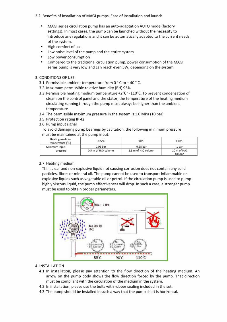
3. CONDITIONS OF USE 3.1. Permissible ambient temperature from 0 ° C to + 40 ° C. 3.2. Maximum permissible relative humidity (RH) 95%
3.3. Permissible heating medium temperature +2℃~110℃. To prevent condensation of steam on the control panel and the stator, the temperature of the heating medium circulating running through the pump must always be higher than the ambient temperature.
3.4. The permissible maximum pressure in the system is 1.0 MPa (10 bar) 3.5. Protection rating IP 42 3.6. Pump input signal
To avoid damaging pump bearings by cavitation, the following minimum pressure must be maintained at the pump input:
Heating medium temperature [OC]
<85℃ 90℃ 110℃
Minimum input pressure
0.05 bar 0.28 bar 1 bar
0.5 m of H2O column 2.8 m of H2O column 10 m of H2O column
3.7. Heating medium Thin, clear and non-explosive liquid not causing corrosion does not contain any solid particles, fibres or mineral oil. The pump cannot be used to transport inflammable or explosive liquids such as vegetable oil or petrol. If the circulation pump is used to pump highly viscous liquid, the pump effectiveness will drop. In such a case, a stronger pump must be used to obtain proper parameters.
4. INSTALLATION 4.1. In installation, please pay attention to the flow direction of the heating medium. An
arrow on the pump body shows the flow direction forced by the pump. That direction must be compliant with the circulation of the medium in the system.
4.2. In installation, please use the bolts with rubber sealing included in the set. 4.3. The pump should be installed in such a way that the pump shaft is horizontal.

4.4. Permissible positioning of the control panel
4.5. Change in arrangement of the control panel
The control panel along with the motor corpus can rotate every 90°. To change
the position of the junction box, perform the following activities:
1. Disconnect the pump from power supply.
2. Close the cut off valves at the inflow and outflow of the pump and perform
decompression;
3. Loosen and remove four bolts fixing the head in the pump body;
4. Rotate the motor into the desired position and fit four openings
for bolts;
5. Insert four ampoule head screws to proper sockets and tighten them;
WARNING!!! The heating medium can have high temperature and pressure,
therefore it is necessary to discharge the liquid from the system or close the cut-off
valves on both sides of the pump before the ampoule head screws are removed.
After the position of the pump control panel is changed, do not start it before
the heating system is refilled with the heating medium or before the cut-off
valves before and after the pump are opened.
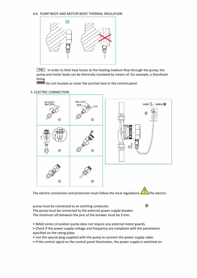
4.6. PUMP BODY AND MOTOR BODY THERMAL INSULATION
In order to limit heat losses at the heating medium flow through the pump, the pump and motor body can be thermally insulated by means of, for example, a Styrofoam lining.
Do not insulate or cover the junction box or the control panel.
5. ELECTRIC CONNECTION:
The electric connection and protection must follow the local regulations. The electric
pump must be connected to an earthing conductor. The pump must be connected to the external power supply breaker. The minimum slit between the pins of the breaker must be 3 mm.
• MAGI series circulation pump does not require any external motor guards. • Check if the power supply voltage and frequency are compliant with the parameters specified on the rating plate. • Use the special plug supplied with the pump to connect the power supply cable. • If the control signal on the control panel illuminates, the power supply is switched on.

6. CONTROL PANEL 6.1. Control panel elements
Numbe
r: Function description: Symbol:
1 AUTO function switch for automatic pump parameter selection depending on the CO system status
AUTO
2 Operating mode change button
3 Operation index acc. to the proportional pressure characteristics (upper and lower range)
BL1/BL2
5 Operation index acc. to the constant pressure characteristics (upper and lower range) HD1/HD2
6 Current consumption in Watt display
7 Operation index acc. to constant rotary speed. 3 ranges: 1-lowest, 3-medium, 3- highest
HS1/HS2/HS3
6.2. Displayed error codes After the power supply is switched on, field no. 6 displays the pump status. During normal operation, the run indicator display is continuously turned on and shows the current power consumption of the operating pump. When the electric pump does not operate properly, the run indicator display will flash, displaying the error codes corresponding to the malfunction type.
Error code: Error description:
E0 Power supply voltage too high
E1 Power supply voltage too low
E2 Blocked rotor and power consumption too high
E3 Pump not vented or too little water in the system
E2-E4 Blocked rotor
If an error is displayed, cut the power supply off to solve the problem. After the problem is solved, turn the power supply on and restart the pump. 6.2. Operating mode selection procedure After the start, the operating mode indicators will be illuminated for a while, and then the pump will set itself into the last operating mode it was in before switch-off. If you press the button no. 2 once, the operating mode will be changed to the next one, in the order as follows: AUTO, BL1, BL2, HD1, HD2, HS3, HS2, HS1 E.g. if the pump operates in the HD1 mode, a single press on the button no. 2 causes switching into the next mode in the list, i.e. mode HD2. Entering into the given mode is signalled by means of illumination of a proper indicator on the panel.
7. OPERATING MODE SELECTION DEPENDING ON THE CENTRAL HEATING INSTALLATION TYPE
Factory settings - AUTO (auto-adaptation mode depending on the central heating system status). Recommended possible pump settings, depending on the heating system type.
Symbol of the
above diagram
System description Pump setting
Optimum Other admissible
A Floor heating AUTO HD1 / HD2
B Heating system with a separate feeding
pipe and separate receiving pipe AUTO BL1 / BL2
C Heating system with a single peripheral
feeding-receiving pipe (serial) BL1 BL1 / BL2
• AUTO (auto-adaptation) adjusts the pump efficiency to the current system heat demand. Since the efficiency is regulated gradually, it is recommended to set the AUTO (auto-adaptation) mode at least a week before changing the pump settings. • If you decide to use the AUTO (auto-adaptation) mode, the MAGI series pump can remember the points from the previous AUTO mode and set the efficiency automatically • The pump settings change from the optimum settings to other optional settings. The heating installation is a free system, it is impossible to reach an optimum operating mode within several minutes or hours. If the optimum pump settings do not reach ideal heat distribution in each room, change the pump settings. • Dependency between the pump settings and the efficiency curve, see chapter 10.1.
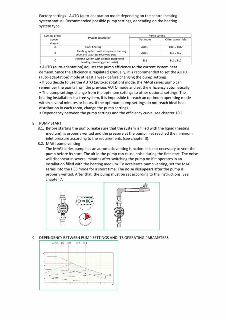
8. PUMP START 8.1. Before starting the pump, make sure that the system is filled with the liquid (heating
medium), is properly vented and the pressure at the pump inlet reached the minimum inlet pressure according to the requirements (see chapter 3).
8.2. MAGI pump venting The MAGI series pump has an automatic venting function. It is not necessary to vent the pump before its start. The air in the pump can cause noise during the first start. The noise will disappear in several minutes after switching the pump on if it operates in an installation filled with the heating medium. To accelerate pump venting, set the MAGI series into the HS3 mode for a short time. The noise disappears after the pump is properly vented. After that, the pump must be set according to the instructions. See chapter 7.
9. DEPENDENCY BETWEEN PUMP SETTINGS AND ITS OPERATING PARAMETERS

Setting Pump operating parameters curve Function
AUTO (factory default setting) From the highest to the lowest curve of proportionate pressure characteristics
- The AUTO function controls the pump efficiency automatically in the specified range. - It adjusts the pump efficiency depending on the system size; - It adjusts the pump efficiency according to the load change for a certain period of time; - In the AUTO mode, the pump is set for the proportional pressure control mode.
BL1 / BL2 Curves of proportionate pressure The operating point will move up and down along the proportional pressure curve depending on the demand of the system flow: when the flow demand decreases - the water pump pressure drops; whereas when the energy demand increases - it increases.
HD1 / HD2 Curves of constant pressure The operating point of the pump moves forward and backward o the constant pressure curve according to the system demand. The water pump pressure remains constant, it has no relation to the flow demand.
HS1/HS2/HS3 Curves of constant rotary speed. HS (1-3), the pump is set for the maximum curve in all operating conditions. If the pump is set in the HS3 mode, the pump will be vented quickly.
10. Efficiency curve 10.1 Efficiency curve guidance Any pump setting will have a proper efficiency curve (Q / H curve). The AUTO (auto-adaptation) mode covers the efficiency scope. The input power curve (P1 curve) belongs to each Q/H curve. The power curve represents the pump power consumption (P1) in Watt for the given Q/H curve. 10.2 Conditions to obtain the curve The description below regards efficiency curves for MAGI series pumps: • Pumped medium: water without gas. • The water density for which the curves were created was ρ= 983.2 kg / m3, temperature: + 60 ° C. • All values expressed with curves are means, they cannot be treated as guaranteed curves. If a specific efficiency is required, carry out a separate measurement for the given pump.
• The curves were created using pumped water kinematic viscosity υ = 0.474 mm2 / s (0.474CcST)
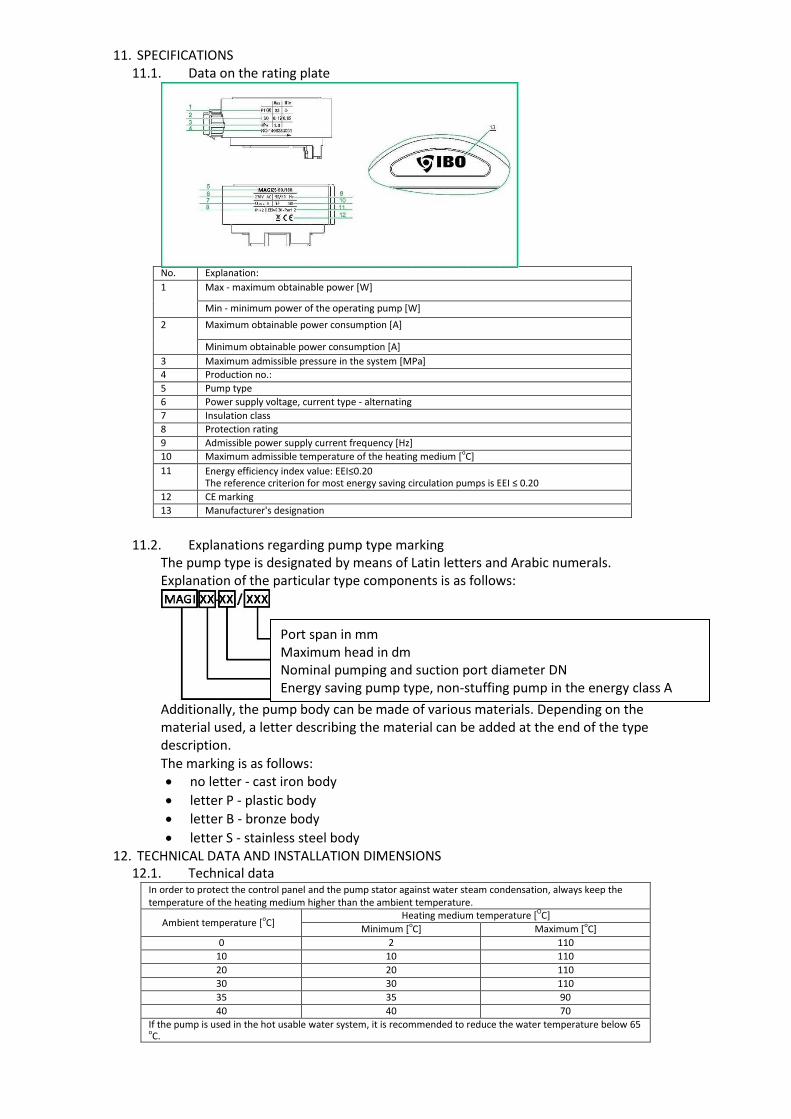
11. SPECIFICATIONS 11.1. Data on the rating plate
No. Explanation:
1 Max - maximum obtainable power [W]
Min - minimum power of the operating pump [W]
2 Maximum obtainable power consumption [A]
Minimum obtainable power consumption [A]
3 Maximum admissible pressure in the system [MPa]
4 Production no.:
5 Pump type
6 Power supply voltage, current type - alternating
7 Insulation class
8 Protection rating
9 Admissible power supply current frequency [Hz]
10 Maximum admissible temperature of the heating medium [oC]
11 Energy efficiency index value: EEI≤0.20 The reference criterion for most energy saving circulation pumps is EEI ≤ 0.20
12 CE marking
13 Manufacturer's designation
11.2. Explanations regarding pump type marking The pump type is designated by means of Latin letters and Arabic numerals. Explanation of the particular type components is as follows:
Additionally, the pump body can be made of various materials. Depending on the material used, a letter describing the material can be added at the end of the type description.
The marking is as follows: no letter - cast iron body
letter P - plastic body
letter B - bronze body
letter S - stainless steel body 12. TECHNICAL DATA AND INSTALLATION DIMENSIONS
12.1. Technical data In order to protect the control panel and the pump stator against water steam condensation, always keep the temperature of the heating medium higher than the ambient temperature.
Ambient temperature [oC] Heating medium temperature [OC]
Minimum [oC] Maximum [oC]
0 2 110
10 10 110
20 20 110
30 30 110
35 35 90
40 40 70
If the pump is used in the hot usable water system, it is recommended to reduce the water temperature below 65 oC.
Port span in mm Maximum head in dm Nominal pumping and suction port diameter DN Energy saving pump type, non-stuffing pump in the energy class A

Power supply 1×230V +6%/-10%,50Hz,PE
Motor protection There is no need for additional motor protection
Protection rating IP 42
Insulation class H
Maximum relative humidity ≤ 95%
Maximum pressure in the central heating system 1 MPa
Minimum inflow pressure at suction depending on heating medium temperature
Medium temperature Minimum inflow pressure
≤ 85 oC 0.005 MPa
≤ 90 oC 0.028 MPa
≤ 110 oC 0.100 MPa
Compliance with EMC standard EN61000-6-1; EN61000-6-3
Acoustic pressure of working pump 43 dB (A)
Permissible ambient temperature 0~+40℃
Maximum heating medium temperature TF110
Maximum heating up of pump surface ≤ 125℃
Range of temperatures of pumped liquid 2~+110℃
12.2. Installation dimensions
Motor power
[W]
Model
Power supply
Material Dimensions [mm]
220~240V 50/60Hz
Cast iron
Plastic Bronze
Stainless steel
L1 L2 B1 B2 H1 H2 G
22
MAGI 20-40P
●
●
65 130 47 93 131 158
1” MAGI 20-40
● ●
● ● 65 130 51 98 133 153
75 150 49 96 131 155
MAGI 25-40
●
●
●
●
65 130 52 99 128 156 11/2” 75 150 49 96 131 155
90 180 52 99 128 156
MAGI 32-40
● ●
90 180 52 99 128 156 2”
32
MAGI 20-50P
●
●
65 130 47 93 131 158
1” MAGI 20-50
● ●
● ● 65 130 52 99 133 153
75 150 49 96 131 155
MAGI 25-50
●
●
●
●
65 130 52 99 128 156 11/2” 75 150 49 96 131 155
90 180 52 99 128 156
MAGI 32-50
● ●
90 180 52 99 128 156 2”
45
MAGI 20-60P
●
●
65 130 47 93 131 158
1” MAGI 20-60
● ●
● ● 65 130 52 99 133 153
75 150 49 96 131 155
MAGI 25-60
●
●
●
●
65 130 52 99 128 156 11/2” 75 150 49 96 131 155
90 180 52 99 128 156
MAGI 32-60
● ●
90 180 52 99 128 156 2”

13. TROUBLESHOOTING
Warning: Before any maintenance or repair activities, make sure that the power supply is cut off and cannot be turned on by accident. Issue: Possible cause: Solution:
The pump fails to launch Tripped installation fuse Check the cause, replace the fuse
Overcurrent circuit breaker switched off Start the breaker
Pump damaged Replace the pump
Voltage too low Check if the main voltage is compliant with the supplier's specification
Pump rotor blocked Unlock the rotor
Loud system operation Air in the installation Vent the installation
Flow too high Decrease the inflow pressure at the pump inlet
Loud pump operation Air in the pump Vent it
Inflow pressure too low - cavitation Increase the inflow pressure at the inlet to the pump
Heat insufficiency in the installation Pump parameters too low If possible, increase the pump operation mode into a more efficient one, otherwise install stronger pump
14. DECLARATION OF CONFORMITY
EC DECLARATION OF CONFORMITY (Module A):
PHU Dambat
Gawartowa Wola 38, 05-085 KAMPINOS, POLAND, e-mail: [email protected]
Under the Act of 30 August 2002 on the conformity system (Journal of Laws of 2004, No.
204, item 2087) we declare with full responsibility that BETA pumps to which this
declaration refers to are consistent with the following guidelines of the Council on legal
regulations unification in member states of EC:
— Low Voltage Directive LVD (2006/95/EC). Applied standard: EN 60335-2-51:2003.
— EMC Directive Applied standards: EN61000-6-1; EN61000-6-3.
— Eco-design Directive (2009/125/EC). Circulation pumps:
Regulation of the Commission (EC) no. 641/2009. Applied standards: EN 16297-1:2012
and EN 16297-2:2012.
15. UTILISATIO
N
Gawartowa Wola 23.04.2017
Adam Jastrzębski
The used product is subject to disposal as wastes only in selective waste collection
systems organised by the Network of Communal Electric and Electronic Waste
Collection Centres. The customer is entitled to return the used equipment to the
network of the electric equipment distributor, at least for free and directly,
if the returned device is of proper type and fulfils the same function as a newly purchased device. It
is prohibited to dispose of electric equipment together with other household wastes.
