map matching and heuristic elimination of gyro drift for - deep blue
TRANSCRIPT

Map matching and heuristic elimination of gyro drift for personal navigation systems in GPS-
denied conditions
This article has been downloaded from IOPscience. Please scroll down to see the full text article.
2011 Meas. Sci. Technol. 22 025205
(http://iopscience.iop.org/0957-0233/22/2/025205)
Download details:
IP Address: 141.211.173.82
The article was downloaded on 06/04/2012 at 16:55
Please note that terms and conditions apply.
View the table of contents for this issue, or go to the journal homepage for more
Home Search Collections Journals About Contact us My IOPscience

IOP PUBLISHING MEASUREMENT SCIENCE AND TECHNOLOGY
Meas. Sci. Technol. 22 (2011) 025205 (12pp) doi:10.1088/0957-0233/22/2/025205
Map matching and heuristic eliminationof gyro drift for personal navigationsystems in GPS-denied conditionsPriyanka Aggarwal1, David Thomas, Lauro Ojeda and Johann Borenstein
The University of Michigan, 2260 Hayward Street, Ann Arbor, MI 48109, USA
E-mail: [email protected] [email protected] [email protected] [email protected]
Received 23 May 2010, in final form 9 December 2010Published 18 January 2011Online at stacks.iop.org/MST/22/025205
AbstractThis paper introduces a method for the substantial reduction of heading errors in inertialnavigation systems used under GPS-denied conditions. Presumably, the method is applicablefor both vehicle-based and personal navigation systems, but experiments were performed onlywith a personal navigation system called ‘personal dead reckoning’ (PDR). In order to workunder GPS-denied conditions, the PDR system uses a foot-mounted inertial measurement unit(IMU). However, gyro drift in this IMU can cause large heading errors after just a few minutesof walking. To reduce these errors, the map-matched heuristic drift elimination (MAPHDE)method was developed, which estimates gyro drift errors by comparing IMU-derived headingto the direction of the nearest street segment in a database of street maps. A heuristiccomponent in this method provides tolerance to short deviations from walking along the street,such as when crossing streets or intersections. MAPHDE keeps heading errors almost at zero,and, as a result, position errors are dramatically reduced. In this paper, MAPHDE was used ina variety of outdoor walks, without any use of GPS. This paper explains the MAPHDE methodin detail and presents experimental results.
Keywords: map-matching techniques, heuristic drift elimination, personal navigationsystems, GPS, inertial sensors
(Some figures in this article are in colour only in the electronic version)
1. Introduction
Pedestrian tracking is the process of determining andmaintaining positional information for a person travelingon foot. Pedestrian tracking systems (PTSs) are usefulfor tracking movements of military personnel, finding andrescuing incapacitated first responders, or for location-awarecomputing and personal navigation assistance [1]. For mostPTSs, GPS is the primary source for obtaining position andvelocity data. Under ideal conditions, GPS provides long-term accurate and absolute measurements. Outdoors, wherethere is a clear line of sight to four or more satellites, GPSprovides location with accuracies ranging from tens of metersto tens of centimeters, depending on the type of GPS receiver[14]. However, GPS is often unavailable in urban areas, where1 Author to whom any correspondence should be addressed.
the urban canyon effect may reduce the number of visiblesatellites. Even when GPS is available, it is often less accuratebecause of multipath effects. Alternative approaches forabsolute PTSs require active radiation sources such as infraredlight [16], ultrasound [17], magnetic fields [18], ultrawideband(UWB) [19] or other radio frequencies [20]. Common to thesemethods is that they require initial setup of the correspondingsources. Many applications exist in which the initial setuptime is not feasible (e.g., firefighting or military) or wherethe installation of such infrastructure is too costly (e.g., cityblocks).
Another approach is to use light emitting and capturingsources such as cameras or light detection and ranging(LIDAR) systems [21]. LIDAR suffers from disturbanceswhen the user walks among other pedestrians, as would be thecase in downtown areas of large cities. Another technology
0957-0233/11/025205+12$33.00 1 © 2011 IOP Publishing Ltd Printed in the UK & the USA

Meas. Sci. Technol. 22 (2011) 025205 P Aggarwal et al
that uses cameras and/or LIDAR is simultaneous localizationand mapping (SLAM), which is based on building a mapwithin an unknown environment (without a priori knowledge)or updating a map within a known environment (with a prioriknowledge from a given map) while at the same time keepingtrack of the current location. SLAM systems may accumulateerrors over time and can fail when used on a busy streetwith pedestrians walking by. A recent development [22] useshead-mounted laser range and inertial sensors to localize aperson in indoor environments, without use of any a prioribuilding or floor map data. All LIDAR-based technologieshave the following limitations in common: have active sourceof radiation which might reveal the military users’ location tothe enemy and the equipment pose is altered when firefighterscrawl on hands and knees for rescue mission. A problemcommon to LIDAR and computer vision systems is that theydo not work well in smoke-filled environments, making themunsuitable for firefighters.
There are a few other radio frequency (RF)-basedtechnologies, such as those using cellular telephones(exploiting time delays) or triangulation methods based onwireless networks for obtaining navigation parameters. Themain limitation of cellular technologies is that they arenot accurate enough for most pedestrian tracking purposes.Wireless local area networks (WLANs) can be used for indoornavigation, where the location fix is determined by measuringsignal strengths from several access points [21]. However,like GPS, this method suffers from multipath and fadingeffects, and often pre-mapping of signal strength is required.Other methods may include active badges or optical trackingsystems that employ specific markers installed in and aroundthe buildings and can assist in detecting the person’s currentlocation [23].
An entirely different approach is the use of relativesensor modalities, predominantly IMUs. IMUs do not requireany external infrastructure and do not actively radiate. Theproblem with IMUs is that the position and heading estimatesderived from the accelerometers and gyros of the IMU developunbounded errors. Moreover and besides their astronomicalcost, very high-end IMUs that develop errors only slowlyare typically too large and heavy to be worn by a person,especially warfighters and first responders who already carrya lot of heavy gear. Smaller and lighter IMUs, typicallyusing micro-electro-mechanical systems (MEMS) technology,develop large position and heading errors quickly. A commonapproach to making MEMS-based IMUs feasible in PTSsapplications is therefore to find ways that allow the boundingof heading and position errors.
The main components of an IMU-based PTS algorithm arefootfall detection, step-length along with altitude estimation,and heading estimation [2–6, 20]. Footfall detection maybe accomplished by examining accelerometer or gyroscopevariances after pre-processing (such as noise reduction byaveraging) [2, 3, 7]. The estimation of step-length can beaccomplished either by GPS updates [3] (when GPS is atleast temporarily available), as a function of step period,acceleration magnitude or acceleration variance [6, 10], bydirect inertial sensor integration [1, 11, 12], or by otheradvanced techniques [15].
One key distinction of IMU-based PTSs is whether theIMU is located on the foot or elsewhere on the body. Locationof the IMU on the body makes system integration morepractical, but existing systems all struggle with the problemof estimating distance traveled, especially when users applydifferent gaits, as well as when walking backward or sideways.Foot-mounted IMUs are more cumbersome to use becausethere are limited options for placing the IMU on or in theuser’s footwear, and typically a cable connection to a body-worn computer is required. However, the great advantageof foot-mounted IMUs is that they allow compensationfor accelerometer drift and thus accurate direct step-lengthmeasurements [7] as will be explained in section 2. In mostIMU-based systems, altitude is not measured by the IMU butrather by barometric pressure sensors [20].
In IMU-based PTSs, the heading or direction of motion ismost commonly obtained from the gyroscopes of the IMU.However, in MEMS-based systems bias drift of the gyrosis significant and if left uncorrected can completely maskthe navigation solution [1, 11, 12]. Therefore, alternativeequipment or additional data sources are required to achievereasonable accuracy. Since heading errors from inertialsensors can grow without bound, reducing heading errorscan dramatically improve position accuracy. Another methodfor obtaining heading information is by using a magneticcompass [2, 10]. A magnetic compass offers absolute headinginformation by measuring the earth’s magnetic field. However,these measurements can be easily distorted by nearby steelstructures or electric fields. For these reasons, magnetometersgenerally do not work reliably enough inside buildings andwork only marginally in urban environments [13].
Map-matching algorithms [24, 25] can also be used forcorrecting heading errors in PTS. Map matching is the processof comparing personal tracking data with the digital mapof streets to match the pedestrian’s navigation data to thestreet segment on which the pedestrian is walking. Thereare several map-matching algorithms such as geometric point-to-point, geometric point-to-curve and geometric curve-to-curve methods. These methods and their shortcomings willbe explained in section 3.2. This paper proposes a modifiedgeometric point-to-curve method to overcome some of thelimitations of these existing map-matching algorithms.
The work was motivated by the goal of creating a PTSthat is capable of tracking walking persons in GPS-deniedurban environments. The focus was on mitigating headingerrors by means of the so-called map-matched heuristic driftelimination method that was developed under this study. Thismethod has two components: (1) obtaining the direction ofthe nearest street segment through map matching and (2)correcting the walker’s estimated heading based on the inertialsensors and the present best estimate of the heading calculatedby the previously developed heuristic drift elimination (HDE)technique.
It should be noted that the term ‘drift elimination’ as usedin this paper is meant to be taken figuratively, not literally. Ofcourse, our method cannot correct gyro drift at the core, namelyinside the gyro. A more precise but stylistically cumbersomename for our method would be ‘heuristics-based elimination of
2

Meas. Sci. Technol. 22 (2011) 025205 P Aggarwal et al
(a) (b)
Figure 1. The foot-mounted IMU of the PDR system has two mounting options: (a) side-mounted IMU (the IMU itself is covered by thebeige-colored thermal insulation), (b) in-heel IMU with temperature-controlled, shock-resistant housing.
the ill-effects of drift and of other slow-changing error sourceson heading estimation’. In the interest of brevity, we chose theshorter term ‘heuristic drift elimination’.
The remainder of this paper is structured as follows.Section 2 describes the earlier developed PDR system.Section 3 describes the TIGER database and OpenStreetMaps(OSMs), where map data are freely available, along withprevious map-matching techniques. The proposed MAPHDEmethod is described in section 4 and results are presented insection 5.
2. The personal dead reckoning system
In earlier work, the Mobile Robotics Laboratory at theUniversity of Michigan developed the personal dead reckoning(PDR) system [7–9, 11]. Using only an IMU for allmeasurements, the PDR system has a zero-radiation signature,i.e. it does not emit any signals. This makes the system‘invisible’ to sensors in hostile environments and immune tointerference or jamming.
2.1. Components of the PDR system
The PDR system uses an IMU strapped to the side of the user’sboot or embedded in the heel of the user’s boot, as shown infigure 1. The side-mounted IMU can be transferred amongdifferent users while the in-heel version better protects theIMU from damage and cannot be dislocated easily. The PDRsystem’s computations are performed on a PC-104 computerthat is located inside a belt pack, together with batteries andsupport electronics. The MEMS-based IMU used in thePDR system is the nano-IMU (‘nIMU’ in short), made byMemsense. Some key specifications for the nIMU are listedin table 1.
The computer runs the Linux operating system patchedwith a real-time extension. An IMU-based position estimationsystem combines two functional components: the estimate ofdistance traveled and the estimate of heading. In the PDRsystem, the accuracy of both components is predominantlyaffected by bias drift (‘drift’, in short). This is especially trueif a relatively low-performance MEMS-based IMU is used.
Table 1. Key specifications of the Memsense nIMU.
Size (mm) 45 × 23 × 13Weight (g) 15Bandwidth (Hz) 75
GyroscopeRange (deg s−1) ±1200Angle random walk (deg h−1/2) 4.2Bias drift (deg h−1) 80
AccelerometerRange (g) ±10
Drift rates for both accelerometers and gyroscopes in a MEMS-based IMU are several orders of magnitude higher than whatis found in high-grade aviation IMUs. Of course, the costof high-grade IMUs is also one or two orders of magnitudehigher than that of the nIMU in the PDR system. However,the reason for using a low-grade IMU in the PDR system isnot just cost. Rather, in order to embed the IMU in the heel ofa regular firefighter or military-style boot, the device must bevery small. Because of this size limitation, the only suitableIMU technology is that of MEMS. Another limiting factor isthe fact that the peak accelerations and rates of turn of thefoot, even at normal walking speed, are significantly higherthan those found on the torso of a person. This limits thechoice of suitable IMUs to less than a handful of models thatoffer the large dynamic range required by that particular IMUlocation.
A foot-mounted IMU makes wiring more difficult,requires greater dynamic ranges of the IMU, and may adddifficulties in heading estimation. However, there is acompelling reason for choosing this mounting location afterall: it is the only way to reset drift of the accelerometersalmost as frequently as once every second and thereby allowsthe accurate determination of step-length, as explained below.
2.2. Estimate of distance traveled
In the PDR system, the estimate of distance traveled isbased on the accelerometers of an IMU. It is well knownthat measured accelerations must be integrated twice to yielddistance traveled. This double integration turns even smallamounts of drift into large position errors. In order to overcome
3

Meas. Sci. Technol. 22 (2011) 025205 P Aggarwal et al
this limitation, a technique known as zero velocity updates(ZUPTs) is used. ZUPT is a well-established techniquefor estimating and counteracting drift in inertial sensors.However, ZUPT is often inconvenient because it can be appliedonly while the sensor has zero velocity. A foot-mounted IMU,on the other hand, lends itself perfectly to the applicationof ZUPT because during walking and many other modes oflegged motion, the sole of the instrumented boot has zerovelocity during parts of a phase of walking called ‘midstance.’To exploit this fact, the PDR system examines the incomingdata from the IMU and flags the instance of minimal footmotion during the midstance phase. This flagged instance ofpresumed zero velocity is called ‘footfall’ in the context of thispaper. The ZUPT method is then implemented by comparingthe accelerometer-derived velocity of the foot to the velocityof the foot during footfall. Since at footfall the velocity shouldbe zero, any accelerometer-derived non-zero velocity estimateat the instance of footfall is considered to be the result of driftand is compensated for.
Another helpful aspect of walking is that footfalls of theinstrumented foot occur with every second step, and thatis almost as frequently as once per second. This assuresthat accelerometer drift is compensated for once per second,thereby not allowing significant drift and position errors toaccumulate. As a result, the PDR system estimates distancetraveled consistently with errors of less than 1% of distancetraveled, on almost all terrains, except for ice, sand, or othernon-solid surfaces. The ZUPT method and its application inthe PDR system are explained in more detail in the authors’earlier papers [7–9, 11].
2.3. Estimate of change in heading
The PDR system estimates changes of heading from the IMU’sgyro data. However, bias drift in the gyros of a MEMS-based IMU is on the order of tens to hundreds of degrees perhour (about 80◦ h−1 in the case of the nIMU). Unfortunately,a method ‘similar to the ZUPT approach’ that works sowell for the PDR system’s accelerometers cannot be used tocompensate for the gyro drift. The main difficulty is that underrealistic walk conditions the shoe heading continues to changeduring the footfall; therefore, it is ‘non-zero’ and a methodsuch as ZUPT would not immediately be applicable.
In earlier work [8] the authors introduced a method, called‘heuristic drift reduction’ (HDR) that partially compensatesfor gyro drift by exploiting the fact that pedestrians often walkalong approximately in straight lines. This is mainly becausepedestrian routes (e.g., sidewalks in urban centers) are oftenstraight and because straight lines are the shortest way to getfrom point A to B. The method of [8] reduced average headingerrors up to fivefold.
In subsequent work [9], the authors introduced asignificantly more effective method, called ‘heuristic driftelimination’. This method is applicable only in indoorenvironments in which corridors and walls are straight andintersect at right angles. In practice, this seemingly severelimitation is met by the vast majority of all buildings. In suchindoor environments, HDE effectively compensates for gyrodrift and other slow-changing heading errors.
Similarly, the key hypothesis or heuristic assumption ofthe work in this paper is that when pedestrians walk alongstreets, they do so predominantly in the general direction ofthese streets. Furthermore, the proposed method presumesthat these streets are mapped with good accuracy and thatthe maps can be obtained in electronic form. Based onthese assumptions, the heuristic method proposed in this papercompares the momentary heading of a walker based on gyroestimates to the known heading of the street segment that thewalker is currently walking on. Any discrepancy is assumedto be due to gyro drift and is compensated for.
However, these heuristic assumptions do not hold true allthe time. In reality, pedestrians do not walk on perfectlystraight lines. Pedestrians cross streets at angles, avoidobstacles and pick occasional shortcuts. Nonetheless, thispaper argues that despite these local aberrations, streetsand walkways channel the motion of pedestrians so that onaverage, the heading of a street segment is a good predictor forthe average heading of the pedestrian along that segment. Thechallenge is to define a practical method that uses the knownheading of street segments to correct gyro drift, while beingtolerant to these local, temporary deviations. The remainderof this paper introduces one such method.
3. Map matching
As a source for digital street maps, the freely available OSM[27] database is used. This database claims a positionalaccuracy range of 7.6 m or better.
3.1. The OSM database
The database of roads used in this study was obtained fromthe OSM database, which is mainly populated by the MasterAddress File/Topologically Integrated Geographic Encodingand Referencing (MAF/TIGER R©) database [26]. This OSMdatabase is a single XML file that is hierarchically composed ofways (including streets, paths, rivers, lakes, legal boundaries,etc), covering the entire United States.
The OSM database is collaboratively updated byvolunteers and is more inclusive and more up-to-date thanthe TIGER database. In the OSM database, straight streetsegments are represented by two points, while curved streetsegments are represented by multiple, rather densely spacedpoints, as shown in figures 2 and 3. The OSM databasecontains digital vector data describing geographic features butit does not include graphic images for visualization.
In preparation for this study, the latitude and longitudeof street centerline points were extracted from OSM databaseand stored in the flash memory of the PDR system. These datawere parsed ahead of time to populate a SQLite database withthe required data. In doing so, streets were split into segmentsof a maximum length of 100 m, to significantly cut down thenumber of viable segments.
4

Meas. Sci. Technol. 22 (2011) 025205 P Aggarwal et al
Figure 2. Typical frequency of points used in the OSM database representation of curved street segments (overlaid over a conventional map,for visualization).
Figure 3. Typical OSM database representation of straight street segments, using only two points (overlaid over a conventional map, forvisualization).
3.2. Map-matching techniques and integration methodsdeveloped by others
A map-matching algorithm identifies the street segmentthat the user travels along. There are several map-matching algorithms and some of them are briefly discussedhere [28].
3.2.1. Geometric point-to-point matching. In this approach,the closest node in the street network database to the user isobtained. This is the simplest, easiest to implement, and fastestmethod, but the accuracy of the solution depends on the waythe street network is digitized. Streets with a greater numberof nodes are more likely to be matched with the user.
3.2.2. Geometric point-to-curve method. With this methoda street segment is identified that is closest to the user, ratherthan the street nodes. From geometry, the minimum distancebetween a point and a line is the perpendicular distance, andthis distance can be readily computed. One problem with thismethod is illustrated in figure 4, where the trajectory is nearest
Uo
U1
U2
U3
A
BUser trajectory
Figure 4. Error in the geometric point-to-curve method nearintersection.
to street A but at point U3 it is equally distant to streets Aand B. In this situation the above-explained algorithm fails
5

Meas. Sci. Technol. 22 (2011) 025205 P Aggarwal et al
to select the correct street segment. Hence, this approachdoes not work well near intersections where different streetscan be equidistant from the walker. Furthermore, the obtainedperpendicular point may be unstable, oscillating back and forthbetween two closely spaced parallel streets common in urbanenvironment [28–31]. A single reading may be matched withseveral street segments, thereby creating an ambiguity in thesolution and causes the user to drift from one parallel street toanother.
3.2.3. Geometric curve-to-curve matching. With thismethod the previous m positions of the user are matched withthe street curve and the nearest street curve is selected as thesolution. This method is very sensitive to outliers and there isno good way to compare curves of different lengths withoutincorporation of GPS data. On connecting GPS data points,a sequence of piecewise linear curves is formed which is thenmatched with a set of possible street segments [25]. Generally,the selected street segment will have the smallest norm distanceto the GPS curve. However, if GPS data are not accurate, thismatching method will produce a wrong match. Furthermore,there should be a sufficient number of GPS readings to form alinear curve for the user’s trajectory.
In this study, a modified geometric point-to-curve methodwas implemented for identifying the nearest street segmentto the walker. In addition, only the direction of the neareststreet was matched to the walker’s estimated heading, sincethe algorithm does not attempt to correct the walker’s positiondirectly.
There are many possible ways of optimally combining themap information with other sources of position information,such as IMU. One such method utilizes the maximum aposteriori (MAP) estimator to optimally translate raw positionmeasurements of a walker onto the street network [32]. AMAP position estimate is obtained by solving the equation
x = arg max[p(x)p(y|x)] (1)
where x is the position estimate of the walker with probabilityp(x), y is the available noisy measurement and p(y|x) representsthe likelihood function.
In cases where the street is a long straight line, it ismodeled by the centerline. Curved streets are modeled bya sequence of piecewise straight-line segments, where eachpiece is treated as a separate street and a locally optimumposition estimate is determined for that piece. However, itis possible that the solution obtained by the unbiased MAPestimator is not unique as the likelihood function may havemultiple local maxima and a wrong street may be identified.The resolution of this problem requires other sources ofposition information to be identified and incorporated intothe estimation process.
One such source is to include information contained inthe walker’s trajectory such that a probability is associatedwith each street. This probability represents the likelihoodof the walker being on that particular street. The easily wayto accomplish this is by means of a Kalman filter (KF) asit associates a probability with each street such that largererrors produce smaller probabilities of being the selected street
segment [3]. However, this approach is not practical becausea KF assumes state variables and noises to have a Gaussiandistribution, which is not always true in a real scenario [3].
Other possible methods are to use fuzzy logic-based map-matching and probabilistic algorithms using inertial sensors[32, 33]. In [32], a set of eight rules is defined for obtainingposition using the map-matching algorithm, inertial sensors,and GPS data. However, in certain cases error growth cancompletely mask the true solution. A confidence region inthe shape of an ellipse or rectangle is defined around thenavigation sensor output, for the probabilistic approach [33].This error or confidence region is then superimposed on amap database to obtain the correct street segment. Even so,additional knowledge may be essential to identify the correctstreet segment from a number of possibilities.
The MAPHDE method uses a modified map-matchingtechnique, but in conjunction with the aforementioned HDEengine, as will be explained in the following section. TheHDE technique is capable of fully compensating for all slow-changing errors including gyro drift, thereby providing near-zero heading errors at steady state. In the context of this study,the steady state is typically reached within a few seconds ofwalking straight along a straight street segment. HDE needsonly four pieces of information to function: distance traveledper footfall, time elapsed since the last footfall, change inheading since the last footfall, and the direction of the neareststreet segment [5]. Furthermore, MAPHDE does not need anymodels or model parameters, as would be required in the caseof KFs. In its simplest form, MAPHDE requires the tuning ofjust three parameters, the gain ic, the distance of the walkerfrom the nearest street segment dmin, and a threshold ψ thres,for the difference between estimated heading from HDE andthe present best estimate of the direction of the nearest streetsegment. Furthermore, HDE takes just a few lines of C-codeto implement. The MAPHDE method is explained next.
4. MAPHDE method
This paper presents a novel method for correcting headingerrors in position tracking systems based on the proposedMAPHDE method. The required real-time input for theproposed method is the rate of rotation about the Z-axisor change in heading, step-length, time interval betweensubsequent footfalls, and initial starting position and heading.Of course, this system also requires its map database tobe populated with pertinent map data. Generally, on 3Dterrain, or with the foot-mounted sensor of the PDR system, afull 6-DOF (degree-of-freedom) IMU is required to estimateheading. Here the notion of a ‘virtual Z-axis gyro’ isintroduced to express the walker’s rate of rotation about thenavigation Z-axis. The PDR system uses the quaternionattitude representation. The output of the virtual Z-axis gyromay be affected by errors such as offset bias, run-to-run bias,in-run bias, scale factor error, misalignment error, sensor drifts,and random noises, etc, which are difficult to identify andmodel or compensate. However, the HDE method treats thecombination of all these sources of error as a single error termwhich overall behaves as drift and the HDE method estimates
6

Meas. Sci. Technol. 22 (2011) 025205 P Aggarwal et al
and compensates for it in real-time. This is the main advantageof the HDE technique as it does not require individual errorsources to be identified and quantified.
When a person equipped with a virtual Z-axis gyro iswalking straightforward, the output of that gyro should beexactly zero throughout the walk. However, due to a variety ofslow-changing and random errors (such as bias drift, sensitivityto linear accelerations, scale factor nonlinearity, and withintegrated white noise), the actual output is off by some smallvalue ε. For simplicity, all these errors are collectively called‘drift’ in this paper. The total travel distance is divided intosmaller intervals, i.e. from footfall to footfall, as defined insection 2.2.
Due to the drift error ε, in each interval the rate of turncomputed based on the Z-axis gyro is
ωmeas,i = ωtrue,i + εi (2)
where ωmeas,i is the rate of turn around the Z-axis during thesampling interval i, ωtrue,i is true but the unknown rate of turnaround the Z-axis during the sampling interval i and εi is thesum of all unknown errors during the sampling interval i.
The change of heading in the sampling interval i, denotedas �ψi , is computed by numerically integrating ωmeas,i :
�ψi = ωmeas,iTi = (ωtrue,i + εi)Ti (3)
where Ti is the duration of the time interval i in seconds. AsTi is the time between footfall i−1 and footfall i, the newestimated heading is
ψi = ψi−1 + �ψi. (4)
It is apparent from equations (2) through (4) that theestimated heading, ψi , represents the true heading plus theaccumulated sum of all heading errors, ψe,i .
4.1. Error correction approaches
A brute force approach to correcting heading errors fromknown street segment directions is to assume that anydifference between the gyro-derived heading and the streetsegment direction is due to gyro-induced errors. Consequently,one can correct the gyro-derived heading by simply replacingit with the appropriate street segment direction. This bruteforce method will fail as soon as the walker actually deviatesfrom the direction of the street, for example, to cross the streetor avoid an obstacle.
In order to allow for the walker’s temporary deviationsfrom the direction of the street, a more subtle approachis needed. For example, instead of completely replacingthe gyro-derived heading by the street direction in everysampling interval, one could add a small correction to the gyro-derived heading. This correction could be proportional to thedifference between street and gyro-derived heading. However,this approach would still react too strongly to actual deviations.For example, when crossing a street the difference between thedirection of the street and the gyro-derived direction can be aslarge as 90◦.
A more deviation-tolerant approach is to add a repetitiveand small, constant-magnitude correction to the gyro-derivedheading. As long as constant-magnitude heading corrections
accumulate faster than drift-induced heading errors, thisapproach can effectively neutralize drift-induced headingerrors. It is also apparent from this discussion that the proposedapproach will not react strongly to temporary deviations,because corrections in response to temporary deviations cannotaccumulate significantly.
The following section formalizes this proposed approachin the form of a feedback control system. Specifically, it willbe shown how the proposed algorithm
• models ψe,i as a disturbance in a feedback control system;• implements a method for accumulating small, constant
magnitude corrections by means of a so-called BinaryI-controller;
• remains largely insensitive to changes in ψ that have largeamplitudes but short duration.
4.2. MAPHDE algorithm
The basic MAPHDE algorithm functions essentially like afeedback control system. This is different from most othermeasuring systems, where signals pass from the sensor to theinstrument’s output in open-loop fashion. Figure 5 showsa block diagram of the feedback control system for theMAPHDE algorithm.
The explanation of the feedback control system starts withthe signal from the gyro, which is modeled as a disturbancein the block diagram of figure 5. Suppose the user is walkingstraight, along a straight section of a linear map feature (forsimplicity, it is assumed that all linear map features are streets,but the proposed algorithm works equally well with floorplans of tunnels or buildings). Immediately after a footfall,the measured rate of turn is integrated to yield the changein heading, �ψi . �ψi has two components, the true butunknown change of heading, �ψ true,i , and the change ofheading error, �ψe,i . Next, �ψi is added to ψi−1 and tothe output of the binary I-controller, which is explained laterin this section. Initially, the output of the I-controller is zero.The label ‘z1
−’ in the feedback loop is the common notation fora pure delay of one sampling interval. After the first iteration,when i > 1, the control loop can be closed by comparingψi−1 to the direction of the closest map feature, ψmap,i−1. Thedifference between them is the error signal E.
Ei = ψmap,i−1 − ψi−1. (5)
Unlike conventional integral (I) or proportional-integral(PI) controllers, the binary I-controller is designed not torespond at all to the magnitude of E; rather, it only respondsto the sign of E. If E is positive (i.e. the measured directionof walking points to the right of the nearest street segment),then a counter (called ‘integrator’ or ‘I’) is incremented by asmall fixed increment, ic, where ic is the gain of the controllerand a tunable parameter in MAPHDE. If E is negative, thenI is decremented by ic. In this fashion, repeated instances ofE having the same sign will result in repeated increments ordecrements of I by ic. The reason for using a binary I-controlleris that Ei can differ from zero by tens of degrees, for example,when the walker is turning. In that case a conventionalI-controller would not work well, since it would respond
7

Meas. Sci. Technol. 22 (2011) 025205 P Aggarwal et al
ωmeas,i = ω true,i+εi
1−z
z
-
z-1
ψi+ψmap,i-1 Binary
I-controller
Integral
Δ Δ Δψi = ψtrue,i+ ψe,i
++Ei
+
ψi-1
Z-axis Gyro(adds εi)
ω true,i
Ii
ψi-1= ψtrue,i-1+ ψe,i-1
Figure 5. The HDE algorithm viewed as a feedback control system. The block labeled ‘Binary I-controller’ is explained in the narrative.
strongly to the large value of E, even though a large E isnot an indication for a large accumulated heading error. Theproposed binary I-controller, on the other hand, is insensitiveto the magnitude of E. Rather, the controller reacts, slowly, toE having the same sign persistently.
As established by equation (5), if ψi−1 > ψmap,i−1 (andthus, E < 0), then ψi−1 is immediately to the left of ψmap,i−1,and if ψi−1 < ψmap,i−1, then ψi−1 is immediately to the rightof ψmap,i−1. During straight-line walking along a street, aheading to the left of ψmap,i−1 suggests that the accumulatedheading error, ψe,i−1, had a positive value. To counteractthis error, the binary I-controller reduces the content of theintegrator by a small value, ic. Conversely, if ψi−1 < ψmap,i−1,then the integrator is increased by ic. Now the binary I-controller can be formulated,
Ii =⎧⎨⎩
Ii−1 − ic for E < 0Ii−1 for E = 0Ii−1 + ic for E > 0
(6a)
where ic is the fixed increment, also considered the gain of thebinary I-controller in units of degrees.
An alternative way of writing equation (6a) is
Ii = Ii−1 + SIGN(ψmap,i−1 − ψi−1)ic (6b)
where SIGN() is a programming function that determines thesign of a number. SIGN(x) returns ‘1’ if x is positive, ‘0’ ifx = 0, and ‘−1’ if x is negative. The next element in the controlloop adds the controller output to the raw measurement to givethe corrected heading:
ψi = ψi−1 + �ψi + Ii . (7)
4.3. Discussion on the MAPHDE algorithm
As long as ic is of greater magnitude than typical incrementsin gyro errors, the integrator continuously tracks the headingerror (but with an opposite sign), just like the integrator in aconventional I-controller tracks slow-changing disturbances.At steady state, i.e. when walking straight along a straightstreet, the content of the integrator will oscillate about theaccumulated heading error, ψe,i , with an amplitude of ic, whichis typically smaller than 1◦. The strength of the MAPHDEalgorithm lies in the fact that it can readily tolerate shortdeviations from walking in the same direction as a street.For example, when dodging other pedestrians on a busy citystreet, when crossing a street, when turning at an intersection,or when walking along a curving street, short deviationsfrom the nominal direction of the nearest street segment areincurred. As a result, MAPHDE may increment or decrementthe integrator in the wrong direction—but only for the durationof the maneuver. However, once motion is aligned again withthe direction of the nearest street segment, it takes just a fewsteps for MAPHDE to correct the incurred error. The streetdirection is obtained by the modified map-matching algorithmas explained in the following section.
It is quite possible that other controllers or filters, such asa finite impulse response (FIR) filter or a KF, can be designedand tuned to act in a way similar to the binary I-controller.However, the intention in this study was not to compare theperformance of different methods. Rather, the intention wasto demonstrate that heading errors due to gyro drift and otherslow-changing errors in a position tracking system can becompensated for and effectively reduced to near-zero (at steadystate) from map data. The proposed MAPHDE control systemseems advantageous because it does not require the explicit
8
Meas. Sci. Technol. 22 (2011) 025205 P Aggarwal et al
Walker’s current position (x3,y3)
Road segment coordinate (x1, y1)
Road segment coordinate(x2, y2)
Nearest point to walker’s position (X,Y)
Figure 6. Coordinates of the street segment, the walker and theperpendicular point.
definition of a model, nor does it require the controlled processto be linear.
4.4. Modified map-matching algorithm
This map-matching algorithm searches the on-board databasefor street segments that meet two conditions.
(1) The segment lies within a pre-defined distance from thewalker (dmin).
(2) The segment has a direction that differs by no more thanψ thres from the walker’s heading.
Once these conditions are met, the perpendicular distancebetween the selected street segments is calculated as follows:
X = m(y3 − y1 + mx1) + x3
m2 + 1(8)
Y = y1 + m(X − x1) (9)
D =√
(X − x3)2 + (Y − y3)2 (10)
where (x1, y1), (x2, y2) are the coordinates of the selected streetsegment as illustrated in figure 6; (X,Y) is the perpendicular
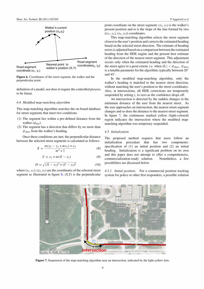
Figure 7. Suspension of the map-matching algorithm near an intersection, indicated by the light-yellow dots.
point coordinate on the street segment; (x3, y3) is the walker’spresent position and m is the slope of the line formed by two((x1, y1), (x2, y2)) coordinates.
This map-matching algorithm selects the street segmentclosest to the user’s position and corrects the estimated headingbased on the selected street direction. The estimate of headingerrors is adjusted based on a comparison between the estimatedheading from the HDE engine and the present best estimateof the direction of the nearest street segment. This adjustmentoccurs only when the estimated heading and the direction ofthe street agree to a great extent, i.e. when |Ei | < ψ thres. ψ thres
is a tunable parameter for the algorithm, typically between 20◦
and 45◦.In the modified map-matching algorithm, only the
walker’s heading is matched to the nearest street direction,without matching the user’s position to the street coordinates.Also, at intersections, all HDE corrections are temporarilysuspended by setting ic to zero as the confidence drops off.
An intersection is detected by the sudden changes in theminimum distance of the user from the nearest street. Asthe user approaches an intersection, the nearest street segmentchanges and so does the distance to the nearest street segment.In figure 7, the continuous marked yellow (light-colored)region indicates the intersection where the modified map-matching algorithm was temporary suspended.
4.5. Initialization
The proposed method requires that users follow aninitialization procedure that has two components:specification of (1) an initial position and (2) an initialheading. Initialization is a significant problem on its ownand this paper does not attempt to offer a comprehensive,commercialization-ready solution. Nonetheless, a fewpossibilities are discussed below.
4.5.1. Initial position. For a commercial position trackingsystem for police or other first responders, a possible solution
9

Meas. Sci. Technol. 22 (2011) 025205 P Aggarwal et al
Figure 8. Trajectory of eight outdoor walks. Light-magenta curve: trajectory from PDR data without MAPHDE correction. Black curve:trajectory from PDR data with MAPHDE correction.
is to implement the tracking system in a hand-held device witha touch screen, similar in size and appearance to a handheldGPS device. The user then indicates his/her initial position bytapping the starting position on the screen that displays a localarea map. Of course, it would be advised to start a walk at
an easily identifiable landmark, such as the intersection of twostreets. If a walk started in an area where GPS was available,but then transitioned into a GPS-denied area, then the last GPS-based position could serve as the initial position for the IMU-tracked portion of the walk. Conceivably, a comprehensive
10

Meas. Sci. Technol. 22 (2011) 025205 P Aggarwal et al
Table 2. Quantitative results for the eight test walks.
Relative RPE Relative RPE ImprovementTotal Return position for uncorrected RPE for for corrected provided by
Total travel error (RPE) for trajectory as corrected trajectory as MAPHDE (ratio ofduration distance for uncorrected percentage of distance trajectory percentage of distance uncorrected to
Walks (min) (m) trajectory (m) traveled (%) (m) traveled (%) corrected RPE)
Walk 1 25.48 2197 890.77 40.6 16.10 0.7 55.3-foldWalk 2 48.12 4344 1739.75 40.1 20.29 0.5 85.7-foldWalk 3 31.56 1814 360.77 19.9 16.51 0.9 21.9-foldWalk 4 31.93 2477 133.21 5.4 11.73 0.5 11.3-foldWalk 5 24.76 1724 160.25 9.3 16.61 1.0 9.6-foldWalk 6 24.12 1575 53.46 3.4 21.18 1.3 2.5-foldWalk 7 23.63 1700 43.68 2.6 10.20 0.6 4.3-foldWalk 8 26.83 2276 148.37 6.5 10.50 0.5 14.1-foldAverage 29.55 2263 441.28 16.4 15.39 0.7 25.6-fold
tracking system could transition from GPS-based to IMU-based tracking automatically, without user intervention.
4.5.2. Initial heading. In a similar approach, initial headingcan be indicated by tapping the same touch screen a secondtime (the first time was for indicating position), at a differentpoint but on the same street. Since a street has only twopossible directions, the second tap would unambiguouslyspecify which of the two directions the user wishes to followinitially. In addition, the user would have to take the first fewsteps in that direction along the street.
5. Experimental results
This section presents the experimental results obtained withthe MAPHDE algorithm by a walking subject in real-time. In all cases, two trajectories are shown. The light-magenta curve shows the output of the PDR system withoutMAPHDE, while the black curve represents the trajectory afterMAPHDE was applied. These results focus on experimentsconsisting of a set of long, complex, closed-loop outdoorwalks.
A total of eight walks of different durations and lengthswere performed on partially sloped streets, as illustrated infigure 8. The three tunable parameters were kept the samefor all of the walks. The walk data are shown using the GPSvisualizer toolbox [34]. Note that ground truth is not shownin these figures due to the unavailability of accurate GPS data.An alternative ground truth, based on the average distanceof the walker from the centerline of the streets (as could bederived from the OSM database) was also not feasible, becausethe subjects usually walked on sidewalks, typically severalmeters away from the streets’ centerlines. Also, the OSMdata specify only a few fixed points to express the positionof curving streets, which is not sufficient to derive groundtruth for a curving street (figure 2). In the absence of useableground truth, graphical results for each of the eight walksare provided in figure 8. A deliberate effort was made tochallenge the MAPHDE method by choosing routes with longcurving segments. For straight streets, MAPHDE would haveperformed even better.
A particular challenge in walk 3 was the routing througha downtown area, where the risk of ‘snapping’ to the wrongstreet was elevated due to the tight grid of streets. It is clearlyvisible that the MAPHDE results did not oscillate back andforth between two closely spaced parallel streets common inthis dense urban environment.
It is apparent from all these trajectories that MAPHDEsubstantially improved position estimation. In order to expressthe performance of MAPHDE qualitatively, a metric called‘return position error’ (RPE) was defined which representsthe difference between the end point as estimated by thePDR system and the starting point of the trajectory. Sincethe subjects started and stopped each walk at the exact samepoint, the estimated trajectories should also start and stop atthe same point. Relative RPE, which is the percentage of RPEdivided by the total traveled distance, was also calculated.Table 2 provides quantitative result for the eight walks.One can see from these results that the uncorrected RPEsvary dramatically, whereas corrected RPEs are consistentlysmall. Other differences in the magnitude of the uncorrectederrors are due to differences in the duration of thewalks.
Although this paper focuses exclusively on the correctionof heading errors, it should be noted that the results infigure 8 and table 2 reflect heading errors as well as errorsin step-length estimation. The latter, however, are very smallin the PDR system thanks to the foot-mounted IMU, whichallows the application of ZUPT with every footfall (as wasexplained in section 2).
6. Conclusion
This paper introduced a method for using known street mapsfor correcting heading errors in an IMU-based personneltracking system. The proposed MAPHDE method combinesa map-matching technique with a heuristics-based correctionalgorithm. The strength of the heuristics algorithm is thatit is tolerant to short-term deviations from walking alongthe directions of streets. Such deviations occur routinelywhen the walker dodges other pedestrians, crosses streets, orturns.
11

Meas. Sci. Technol. 22 (2011) 025205 P Aggarwal et al
Because of the difficulty of recording accurate groundtruth data (a high-accuracy differential GPS system would haveto be used), plots of all eight outdoor walks overlaid over a mapare provided. The plots show the uncorrected and MAPHDE-corrected trajectories and thereby illustrate the effectivenessof the MAPHDE method. It is also evident from the plotsthat by reducing heading errors to near-zero at steady state,position errors are reduced substantially. The quantitativeresults in table 2 show that MAPHDE reduces return positionerrors on average to less than 1% of distance traveled,providing a 25-fold reduction in return position errors onaverage.
Acknowledgments
This research was supported in part by the Ground RoboticsReliability Center (GRRC) at the University of Michigan, withfunding from government contract DoD-DoA W56H2V-04-2-0001 through the Joint Center for Robotics.
References
[1] Foxlin E 2005 Pedestrian tracking with shoe-mounted inertialsensors IEEE Comput. Graph. Appl. 25 38–46
[2] Mezentsev O, Collin J, Kuusniemi H and Lachapelle G 2004Accuracy assessment of a high sensitivity GPS basedpedestrian navigation system aided by low-cost sensors11th Saint Petersburg Int. Conf. on Integrated NavigationSystems (St Petersburg, 24–26 May 2004)
[3] Basnayake C, Mezentsev O, Lachapelle G and Cannon M E2005 An HSGPS, inertial and map-matching integratedportable vehicular navigation system for uninterruptedreal-time vehicular navigation Int. J. Veh. Inform. Commun.Syst. 1 131–51
[4] Kim J W, Jang H J, Hwang D-H and Park C 2004 A step,stride and heading determination for the pedestriannavigation system J. Glob. Positioning Syst.3 273–9
[5] Ladetto Q, Gabaglio V and Meminod B 2001 Combininggyroscopes, magnetic compass and GPS for pedestriannavigation Int. Symp. on Kinematic Systems in Geodesy,Geomatics and Navigation (Banff, AB, Canada, 5–8 June)
[6] Stirling R, Collin J, Fyfe K and Lachapelle G 2003 Aninnovative shoe-mounted pedestrian navigation systemCD-ROM Proc. GNSS, the European Navigation Conf.pp 103–12
[7] Ojeda L and Borenstein J Personal dead-reckoning system forGPS-denied environments IEEE Int. Workshop on Safety,Security, and Rescue Robotics (SSRR2007) (Rome, Italy,27–29 Sept. 2007)
[8] Borenstein J, Ojeda L and Kwanmuang S 2009 Heuristicreduction of gyro drift in a personal dead reckoning systemJ. Navig. 62 41–58
[9] Borenstein J and Ojeda L 2010 Heuristic drift elimination forpersonnel tracking systems J. Navig. 63 591–606
[10] Judd T 1997 A personal dead reckoning module Institute ofNavigation’s ION 97 (Kansas City, MO, Sept.1997)
[11] Ojeda L and Borenstein J 2006 Non-GPS navigation foremergency responders Int. Joint Topical Meeting: SharingSolutions for Emergencies and Hazardous Environments(Salt Lake City, UT, 12–15 Feb.)
[12] Brand T and Philips R 2003 Foot-to-foot measurement as anaid to personal navigation Institute of Navigation AnnualMeeting 59th (Albuquerque, NM, 23–25 June)
[13] Stirling R, Collin J, Fyfe K and Lachapelle G 2003 Aninnovative shoe-mounted pedestrian navigation systemProc. European Navigation Conf. (Graz, Austria, 22–25April)
[14] Misra P and Enge P 2006 Global Positioning System, Signals,Measurements, and Performance (Lincoln, MA:Ganga-Jamuna Press)
[15] Moafipoor S, Grejner-Brzezinska A D and Toth C K 2008 Afuzzy dead reckoning algorithm for a personal navigatorNavig. ION J. 55 241–55
[16] Butz A, Baus J and Kruger A 2000 Augmenting buildings withinfrared information Proc. Int. Symp. on Augmented Reality(IEEE Computer Society Press) pp 93–6
[17] Cho S Y and Park C G 2006 MEMS based pedestriannavigation system J. Navig. 59 135–53
[18] Newman J, Ingram D and Hopper A 2001 Augmented realityin a wide area sentient environment Proc. IEEE and ACMInt. Symp. on Augmented Reality pp 77–86
[19] Saeed R A and Khatun S 2006 Performance of ultra-widebandtime-of-arrival estimation enhanced with synchronizationscheme ECTI Trans. Electr. Eng., Electron. Commun.4 78–84
[20] Eggert R and Raquet J 2004 Evaluating the navigationpotential of the NTSC analog television broadcast signalProc. ION GNSS-2004 (Long Beach, CA, Sept. 2004)pp 2436–46
[21] Jarvis A M Y 2008 Integration of photogrammetric andLiDAR data for accurate reconstruction and visualization ofurban environments MSc Thesis University of Calgary,UCGE Report 20282
[22] Cinaz B and Kenn H 2008 HeadSLAM—simultaneouslocalization and mapping with head-mounted inertial andlaser range sensors ISWC (Pittsburgh, PA)
[23] Retscher G 2004 Multi-sensor systems for pedestriannavigation ION GNSS 2004 Conf. (Long Beach, CA, 21–24Sept. 2004)
[24] Pahlavan K, Li X and Makela J-P 2002 Indoor geolocationscience and technology IEEE Commun. Mag. 40 112–8
[25] Bernstein D and Kornhauser A 1998 Map matching forpersonal navigation assistants Proc. 77th Annual Meeting ofthe Transportation Research Board (Washington DC, 11–15Jan.)
[26] US Census Bureau Geography 2002 TIGER page:cartographic boundary files, available athttp://www.census.gov/geo/www/tiger (accessed 2 May2009)
[27] OpenStreetMap, available at http://www.openstreetmap.org(accessed 10 July 2009)
[28] Greenfeld J S 2002 Matching GPS observations to locationson a digital map Proc. 81st Annual Meeting of theTransportation Research Board (Washington, DC)
[29] Kim W, Jee G and Lee J 2000 Efficient use of digital road mapin various positioning for ITS IEEE Symp. on PositionLocation and Navigation (San Diego, CA)
[30] Fu M, Li Jie and Wang M 2004 A hybrid map matchingalgorithm based on fuzzy comprehensive Judgment IEEEProc. on Intelligent Transportation Systems pp 613–7
[31] Quddus M A, Ochieng W Y, Zhao L and Noland R B 2003 Ageneral map matching algorithm for transport telematicsapplications GPS Solut. 7 157–67
[32] Scott C A and Drane C R 1994 Increase accuracy of motorvehicle position estimation by utilizing map data: vehicledynamics and other information sources Proc. VehicleNavigation and Information Systems pp 585–90
[33] Retscher G 2006 An intelligent multi-sensor system forpedestrian navigation J. Glob. Positioning Syst., GPS Solut.5 110–8
[34] GPS Visualizer: Do-It-Yourself Mapping 2003 Available athttp://www.gpsvisualizer.com (accessed 31 Dec. 2009)
12